
2015 DOE Vehicle Technologies Program Review Presentation · 2015 DOE Vehicle Technologies Program...
16
2015 DOE Vehicle Technologies Program Review Presentation June 9 th , 2015 Principal Investigator: Dr. John Arnold Presented by: Gary Voelker, Project Director This presentation does not contain any proprietary, confidential, or otherwise restricted information Project ID: ES132 Dramatically Improve the Safety Performance of Li ion Battery Separators and Reduce the Manufacturing Cost Using Ultraviolet Curing and High Precision Coating Technologies Project Timeline : Start Date:10/01/2014 End Date: 9/30/2016 Percent Complete: 25% Project Budget DOE Share $1,955,000 Cost share $ 399,000 June 10, 2015 Dr. John Arnold, Principal Investigator
Transcript of 2015 DOE Vehicle Technologies Program Review Presentation · 2015 DOE Vehicle Technologies Program...

2015 DOE Vehicle Technologies Program Review Presentation
June 9th, 2015
Principal Investigator:Dr. John Arnold
Presented by:Gary Voelker,
Project DirectorThis presentation does not contain any proprietary, confidential, or otherwise restricted information
Project ID:ES132
Dramatically Improve the Safety Performance of Li ion Battery Separators and Reduce the Manufacturing Cost Using Ultraviolet Curing and High Precision Coating Technologies
Project Timeline:Start Date:10/01/2014End Date: 9/30/2016Percent Complete: 25%
Project BudgetDOE Share $1,955,000Cost share $ 399,000
June 10, 2015Dr. John Arnold,Principal Investigator

Major Milestones
Milestone Date StatusComplete UV curable binder characterization 12/15/2014 Complete
Complete UV Curable Binder formulation corrected for printing applications 03/15/2015 Complete
Complete Printing Pattern Characterization 06/24/2015 In Process
Separator Coating Laboratory Testing Complete 08/24/2015 In Process
Complete Coated Separator Electrochemical Evaluation (Go/No-Go) 09/30/2015 Pending
Complete Initial Printing Press application Validation Tests 12/15/2015 Pending
Complete Final Printing Press Tests 08/20/2016 Pending

•Safety• Reduce Possibility of Thermal Runaway
– High melt integrity– Low shrinkage– High compression strength– Less hot spot propagation
Why Ceramic Coated Separators?

l
• Performance– Reduce Dendrite Growth– Increase Ion Path Tortuosity
• Reduce Oxidation of Separator– High Voltage Stability
Why Ceramic coated Separators?

• Start with liquid UV curable mixture (oligomers, monomers, photoinitiators)
• Add ceramic particles• Apply slurry coating• UV cure liquid slurry • 2-6 µm ceramic layer• No Solvent• High Speed Coating
Ceramic Coated Separator using UV Curable Binder Process

Ceramic Coated Separatorusing UV Curable Binder
StatusUV binder chemistries identified
16-25 µm tri-layer and single layer separators successfully coated
Solid and patterned coatings applied
<10% decrease in porosity confirmed
Shrinkage improved over base separator

Laboratory Press Printing at 200 fpm
• Sub-micrometer Coating Thickness Control
• Thinner Coatings,• Less Weight• More Ion Flow • Reduced Cost
• Patterns for Higher Ion Flow
• Versatile Printing or Coating
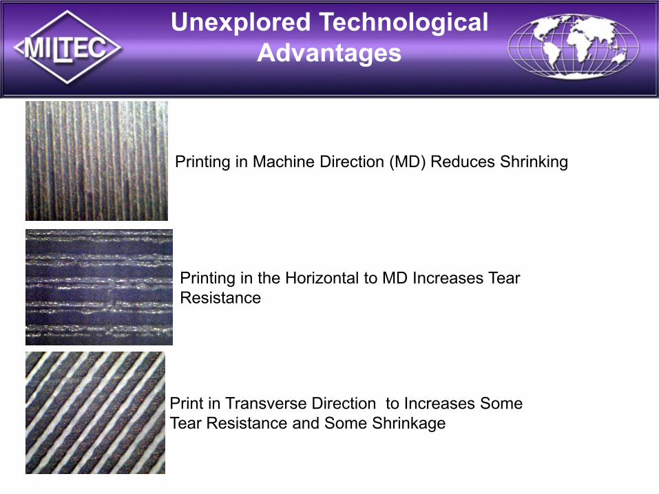
Print in Transverse Direction to Increases Some Tear Resistance and Some Shrinkage
Unexplored Technological Advantages
Printing in Machine Direction (MD) Reduces Shrinking
Printing in the Horizontal to MD Increases Tear Resistance

Novel Printed Patterns

Properties Solid Patterned Base FilmGurley 602 562 461Shrinkage @ 100oC <5% <5% <5%
Shrinkage @ 150oC 24% 28% 33%
Thickness 3 µm+16 µm
3 µm+16 µm
16 µm
UV Ceramic Coatings have Excellent Adhesion and
Porosity

NMC-Lithium Metal Half-Cell
UV Ceramic Coating on Trilayer Separator does not
Interfere with Cell

Cap
acity
, mA
h/g
0
50
100
150
200
UV Coated Separator
Uncoated Separator
0.1 C 0.2 1.0 C 2.0 C0.5 C
Charge Rate
NMC Half Cell
Charge Capacity/Charge Rate Same UV Ceramic Coated & Uncoated

Properties Coated PPOUncoated PPO
Separator
Gurley at 25oC 400 325
Gurley after 100oC 550 300
Gurley after 150oC ∞ 825
Shrinkage @ 100oC <5% <5%
Shrinkage @ 150oC 20% 25%
Thickness 3 µm+16 µm 16 µm
Shut Down CoatingOn Single Layer PP Separator

Gurley Tester Measures Flow Through Coated and
Uncoated Separator

Summary
• Established Feasibility of UV Binder for Ceramic Coated Separator
• 2-6 µm Thick Coatings and Patterns
• Minimum Increase in Gurleys – Less Than 10%
• Demonstrated High Speed Printing (200 ft/min)
• Demonstrated Capable of Printing Patterns

• DOE for their funding contributions and advice
• Partners
Thank You


