2015-2016 NASA SL Proposal Rensselaer Rocket Society (RRS)
85
2015-2016 NASA SL Proposal Rensselaer Rocket Society (RRS) Rensselaer Polytechnic Institute 1999 Burdett Avenue Troy, NY 12180 Project Name: Red Gemini Task 3.1.1 – Atmospheric Measurements Task 3.1.6 – Aerodynamic Analysis Friday, September 11 th , 2015
-
Upload
nguyenhanh -
Category
Documents
-
view
220 -
download
3
Transcript of 2015-2016 NASA SL Proposal Rensselaer Rocket Society (RRS)
2015-2016 NASA SL Proposal
Rensselaer Rocket Society (RRS)
Rensselaer Polytechnic Institute
1999 Burdett Avenue
Troy, NY 12180
Project Name: Red Gemini
Task 3.1.1 – Atmospheric Measurements
Task 3.1.6 – Aerodynamic Analysis
Friday, September 11th, 2015
Rensselaer Rocket Society 2015 - 2016
1
1. Table Of Contents
1. Table Of Contents
2. School Information
2.1. Organization Name
2.2. Faculty Advisor
2.3. Safety Officer
2.4. Student Participants
2.4.1. Administrative, Point of Contact
2.4.2. Student Organization
2.4.2.3. Team Leaders
2.4.2.4. Project Organization
2.4.3. Student Resumes
2.5. NAR/TRA Mentor
2.6. NAR/TRA Sections
3. Facilities & Equipment
3.1. Description
3.2. Personnel
3.3. Computer Equipment
4. Safety
4.1. NAR/TRA Mentor
4.2. Safety Plan
4.2.1. NAR/TRA Personnel Actions
4.2.2. Hazard Recognition and Accident Avoidance
4.2.2.1. Safety Briefings
4.2.2.2. Caution Statements
Rensselaer Rocket Society 2015 - 2016
2
4.2.2.3. Safety Statement
4.3. Compliance with Federal Regulation
4.4. Hazardous Material Storage
4.5. Hazardous Material Transport and Use
4.6. Risk Assessment
4.6.1. Material Hazards
4.6.2. Facility and Tool Hazards
4.6.3. Hazards to Project Completion
4.7. Range Inspections
5. Technical Design
5.1. Vehicle Design
5.2. Payload Design
5.2.1. Payload design:
5.2.2. Microprocessor architecture:
5.2.3. Structural Assembly:
5.3. Recovery Design
5.3.1. Recovery Mechanics:
5.3.2. Recovery Electronics:
5.4. Challenges and Solutions
5.4.1. Vehicle Aspects
6. Educational Engagement
6.1. Soda Bottle Rockets and Open House
6.2. Test Launch
6.3. Girl Scouts Egg-Drop
6.4. Girl Scouts Model Rocket Launch
7. Project Plan
Rensselaer Rocket Society 2015 - 2016
3
7.1. Timeline
7.2. Budget
7.3 Additional Community Support
7.4 Plan for Sustainability
Appendix
Appendix A: Resumes
Appendix B: Budget
Appendix C: Timeline
Appendix D: FAA Regulations
Appendix E: High Power Rocket Safety Code
Appendix F: Safety Statement
Appendix G: Material Safety Data Sheets
Rensselaer Rocket Society 2015 - 2016
4
2. School Information
2.1. Organization Name Rensselaer Rocket Society Rensselaer Polytechnic Institute Troy, NY, 12180
2.2. Faculty Advisor Dr. Jason Hicken Rensselaer Polytechnic Institute
Professor: Introduction to Engineering Analysis, Introduction to Multidisciplinary Design Optimization
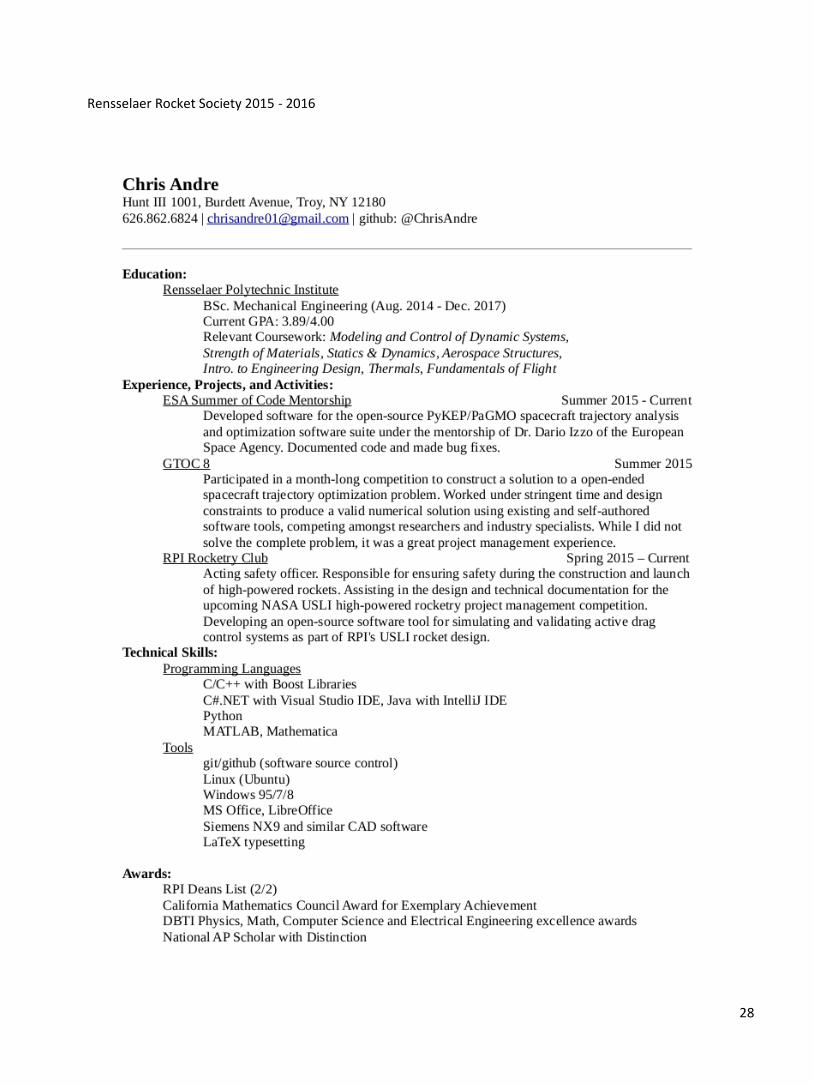
2.3. Safety Officer Christopher Andre Rensselaer Polytechnic Institute ‘18 Mechanical Engineering [email protected]
2.4. Student Participants
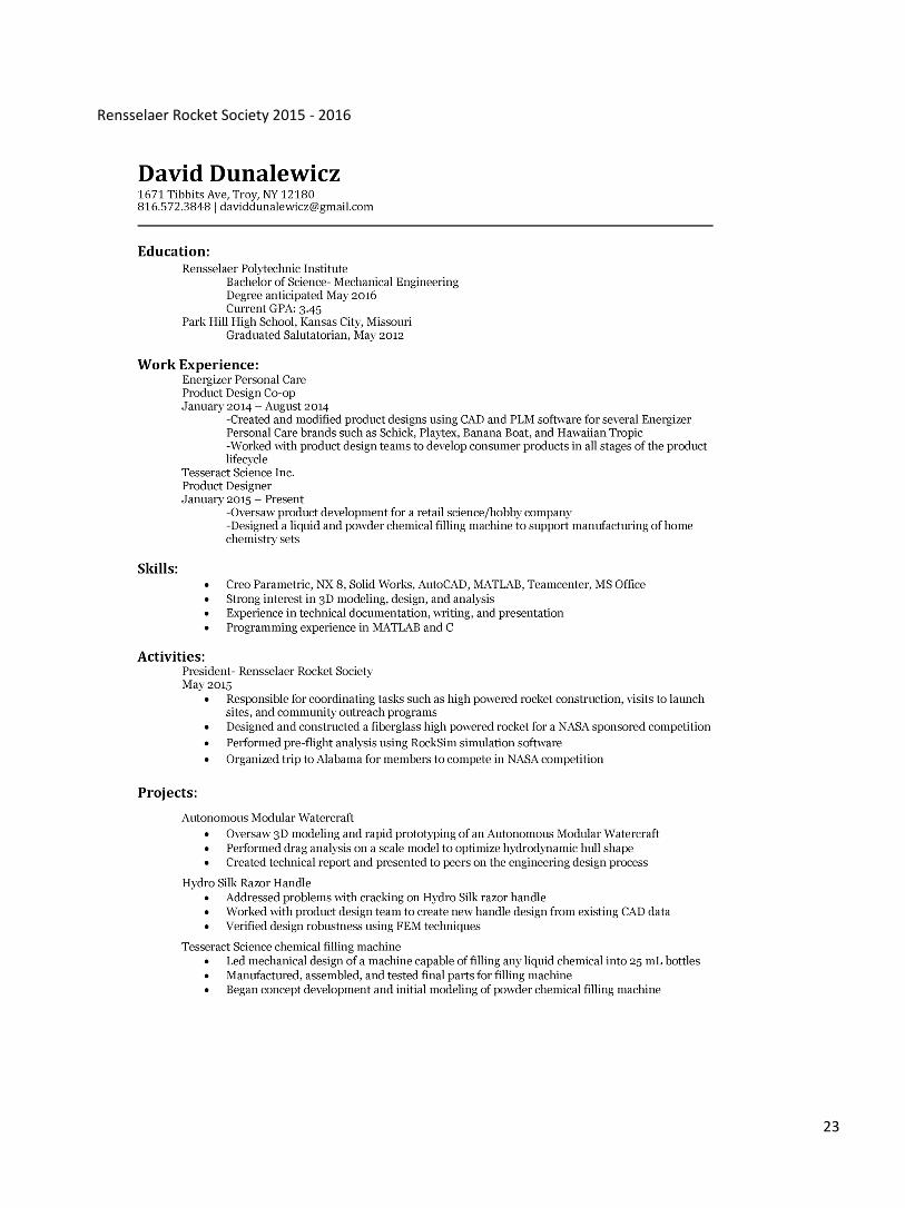
2.4.1. Administrative, Point of Contact David Dunalewicz, Club President Rensselaer Polytechnic Institute ‘16 Mechanical Engineering [email protected]
2.4.2. Student Organization The club is divided into three (3) separate teams which design and develop the various aspects to the rocket. The organization is divided into the Rocket Design Team, Payload Design Team, and Recovery Design Team. Each team has a team lead in charge of the overall development of their subsystem. There will be 49 participants working on the project. 2.4.2.1. Leadership Positions
David Dunalewicz o President
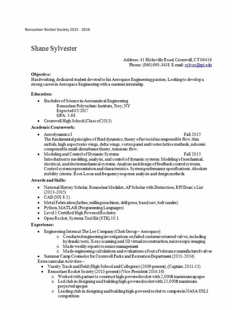
o Mechanical Engineering 2016 Shane Sylvester o Vice President
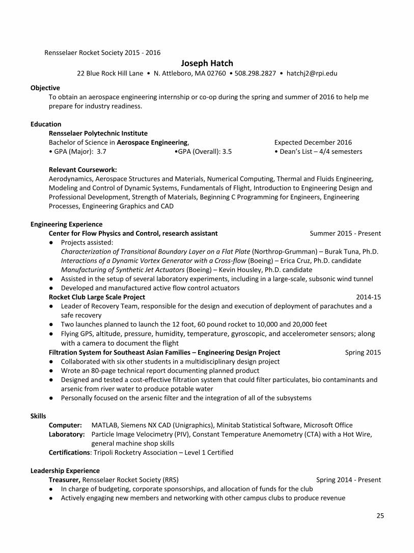
o Aeronautical Engineering 2017 Joseph Hatch o Treasurer
o Aeronautical Engineering 2017 Ryan Manske o Secretary o Computer Science 2018
Rensselaer Rocket Society 2015 - 2016
5
Christopher Andre o Safety Officer
o Mechanical Engineering 2018
2.4.2.3. Team Leaders
Matthew Carr o Payload Design Team (PDT) Lead
o Designs structure and layout of engineering payload(s) for the rocket. Designs communication system between rocket and group systems. Initial tasks are determining approximate size and weight of payload. Charles Goepfert o Vehicle Design Team (VDT) Lead
o Manages exterior proportions of the rocket. Main initial tasks are overall size, weight and engine to be used for the rocket. Works strongly with PDT. Jonathan Williams o Recovery Design Team (RDT) Lead
o Manages design and testing of two stage recovery system. Implements flight computer for any and all in-flight actions.
2.4.2.4. Project Organization
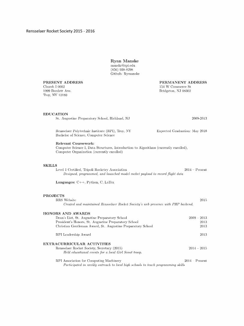
2.4.3. Student Resumes See Appendix A for Resumes
Rensselaer Rocket Society 2015 - 2016
6
2.5. NAR/TRA Mentor John Sicker Atmospheric Science Research Center, SUNY Albany NAR Level 2 Certified, TRA Level 3 Certified [email protected]
2.6. NAR/TRA Sections
● ASTRE NAR Sec. 471: Albany Rocket Enthusiasts
● Tripoli Albany Prefecture 99
3. Facilities & Equipment
3.1. Description The Rensselaer Rocket Society has full access to a variety of locations on the RPI campus to conduct all necessary designing, fabricating and testing procedures needed for large-scale rockets and engineering payloads. The main location for meetings and design sessions is located in room 401 in the Ricketts building on campus. This location provides ample amount of space for all group and team members to meet and has a large, central blackboard to properly brief and showcase aspects of the rocket to the team as a whole. Portable projection equipment will also be used to conduct these briefings and showcasings. Fabrication of the rocket will take place in multiple areas of the Jonsson Engineering Center (JEC), as well as in the meeting and design room, Room 401, in the Ricketts building on the Rensselaer campus. RRS officers have access to this room at all times. Members have access during meetings on Mondays and Wednesdays, 7pm - 9 pm, as well as during additional build hours as needed. The RRS has access to the student machine shop (JEC 1010) weekdays during various morning, afternoon, and evening hours and the Mercer Laboratory (JEC 6204) at all times. The Mercer Laboratory houses a large number of tools and instruments for electronics design and testing. Testing of individual rocket systems will take place in the appropriate areas of the JEC and/ or Ricketts building. Rensselaer provides a variety of locations on campus to use for video conferencing. These areas are easily reserved through the Rensselaer Union.
3.2. Personnel The Rensselaer Rocket Society is a completely student run club under the leadership of current club president, David. The Safety Officer, Christopher, will ensure compliance with all federal, state, and institute policies regarding the use of high power rocket engines. The club mentors from Rensselaer, TRA and NAR will provide guidance and mentorship from the design to final stages of rocket development. Club Mentors as well as the Safety Officer will ensure that all manufacturing processes are done safely and efficiently. For any additional help, the RRS will contact the local NAR/TRA chapter for experienced rocketeers.
3.3. Computer Equipment All members of the RRS have a personal computer to use for designing, simulating, modeling, and analyzing the rocket’s performance. All computers have access to RPI’s wireless network which covers the entirety of campus. Through this network and the Student Help Desk located in the Voorhees Computing Center (VCC), all club members have access to the following programs:
● Adobe Suite ● Fluent ● LabVIEW
Rensselaer Rocket Society 2015 - 2016
7
● Maple ● Mathematica ● Matlab ● Microsoft Office ● NX (Unigraphics) ● Solidworks ● Open Rocket ● many others
In addition, the club has purchased copies of RockSim 9 to be used for the design of the Rocket. All data is shared amongst all team members’ personal computers to ensure information communication and prevent data from being lost on a sole machine. The resources available to the RRS students make for an effective and fast moving team dynamic.
4. Safety
4.1. NAR/TRA Mentor John Sicker is a level 2 certified member of the NAR and a level 3 certified member for the TRA, and has agreed to be the mentor for our team. He will provide guidance for safe and proper sport rocketry practices and will be responsible for all safety inspections. The team’s Safety Officer, Chris, will accompany Mr. Sicker on all such inspections. For liability purposes, Mr. Sicker is designated as the owner of our proposed rocket.
4.2. Safety Plan
4.2.1. NAR/TRA Personnel Actions Mr. Sicker will be responsible for purchasing, storing, transporting, and assembling all motor components containing APCP. As he is more experienced in high-power rocket construction, he will also supervise the construction of the rocket and the use of hazardous materials. Mr. Sicker will also help students achieve the necessary NAR or TRA certification so that they may also purchase, store, transport, and assemble motor components containing APCP. Mr. Sicker and NAR or TRA certified student members will be the people allowed to handle motors and the rocket once the motor is installed. They will also be present at test launches and will conduct the actual launch. Mr. Sicker will ensure that all activities are conducted according to the NAR and TRA high power rocket safety codes.
4.2.2. Hazard Recognition and Accident Avoidance All team members will be briefed on the NAR and TRA high power rocket safety codes, and will be expected to abide by it. All aspects of the rocket design will be checked to ensure adherence to the safety code. Before team members are allowed to handle any hazardous materials required in our rocket’s construction, they will refer to the materials MSDS and be thoroughly familiar with all handling procedures outlined in the MSDS. Hard copies of the MSDS for all needed materials will be available in the lab space, and any member handling any material for the first time will first read that material’s MSDS. Safety inspections will be conducted before each launch.
4.2.2.1. Safety Briefings
Safety briefings will be conducted before the start of each building and testing phase and before all launches. These will include, as appropriate, proper use of tools; proper lab procedures, including appropriate clothing; proper handling of composites and chemicals; proper launch procedures and launch etiquette; and locations of first aid stations and appropriate emergency response.
Rensselaer Rocket Society 2015 - 2016
8
4.2.2.2. Caution Statements
Caution statements will be included in all working documents, and will contain relevant information
from appropriate MSDS. All MSDS will be available in the lab and on the team website.
4.2.2.3. Safety Statement
The team safety officer has signed a written statement regarding his duty to ensure that all team
members will understand and abide by the safety regulations detailed in the 2016 NASA SL
Handbook (Section 4). See Appendix F.
4.3. Compliance with Federal Regulation
All team members will be made aware of and briefed on the following federal regulations: Federal Aviation Regulations 14 CFR, Subchapter F, Part 101, Subpart C; and fire prevention, NFPA 1127 “Code for High Power Rocket Motors.” As of March, 2009, APCP is no longer considered an explosive, and must not be sold or handled as such; however, only NAR or TRA certified team members and Mr. Sicker will be allowed to handle motors or motor components containing APCP.
4.4. Hazardous Material Storage All storage lockers in the team’s lab space are rated to store hazardous materials, including rocket motors. All hazardous materials needed for the rocket’s construction, including motors, will be locked in the lockers when not in use. Motors will be stored separately from other components, such as composites. Only NAR or TRA certified members and Mr. Sicker will have the keys to the locker containing the motors; members trained to handle other materials will have the keys to the respective lockers those materials are stored in. However, this locker and any hazardous materials, including the rocket motor, will be stored off-campus in a more secure lab space with our community mentor, John Sicker, due to university regulations.
4.5. Hazardous Material Transport and Use The motors will be transported via personally owned vehicle to Huntsville, AL. Only NAR or TRA certified members will be allowed to handle the motors, and the motors will be in containers rated for the transport of hazardous materials. Only NAR/TRA certified members will be allowed to handle the motors in preparation for use.
4.6. Risk Assessment The following outlines safety risks and their mitigations that are likely to be encountered in the construction and testing of the rocket.
4.6.1. Material Hazards Solid rocket boosters, epoxies, resins, solder, and other chemicals and materials needed for the construction of the rocket can cause burns, skin and/or eye irritation, and/or may have risks associated with fumes. Mitigations include an orderly workspace; familiarity with relevant MSDS; wearing appropriate clothing and splash-proof eyewear; and knowledge of locations of first aid stations.
4.6.2. Facility and Tool Hazards Tools such as lathes, mills, presses, and other equipment found in the lab present risks in the forms
of cuts, burns, bruises, broken bones, and damage to eyes. Mitigations include having a single,
experienced operator on a tool at a time; minimization of distraction during tool operation;
refraining from wearing loose clothing while operating tools; touching of tools or machines only
Rensselaer Rocket Society 2015 - 2016
9
after they have stopped spinning or have cooled down; proper tool maintenance and handling; and
knowledge of locations of first aid stations.
4.6.3. Hazards to Project Completion Adverse weather conditions may inhibit test launches. This risk is mitigated by scheduling test launches before winter weather conditions inhibit test launches and by setting flexible test launch windows so that launches are easily rescheduled in the event of unforeseen adverse weather conditions. The inability of Mr. Sicker to be present at all test launches and at Huntsville, AL, can be mitigated by ensuring that there is at least one team member present at all launches and at Huntsville who is NAR or TRA certified. Damage to the rocket during test launches or the final competition can be mitigated by having spare parts on hand and by constructing the rocket with standard sized, easily-obtainable components.
4.7. Range Inspections All team members understand that a range safety inspection of each rocket will be held before the rocket
will be flown, and the team will comply with the determination of the safety inspection. Furthermore, it is
understood that the Range Safety Officer (RSO) has the final say on all safety-related rocket issues, and that
the RSO has the right to deny any rocket launch for safety reasons. Finally, the team understands that failure
to comply with safety requirements will result in the rocket being disqualified from launch.
5. Technical Design
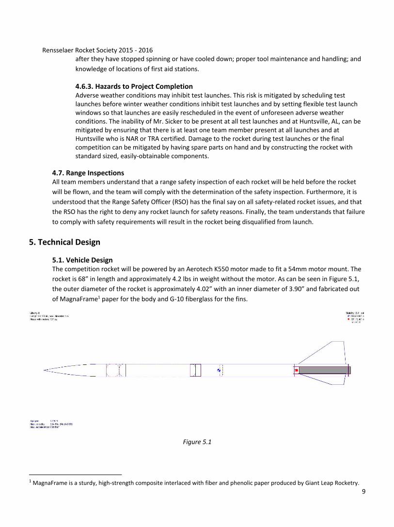
5.1. Vehicle Design The competition rocket will be powered by an Aerotech K550 motor made to fit a 54mm motor mount. The
rocket is 68” in length and approximately 4.2 lbs in weight without the motor. As can be seen in Figure 5.1,
the outer diameter of the rocket is approximately 4.02” with an inner diameter of 3.90” and fabricated out
of MagnaFrame1 paper for the body and G-10 fiberglass for the fins.
Figure 5.1
1 MagnaFrame is a sturdy, high-strength composite interlaced with fiber and phenolic paper produced by Giant Leap Rocketry.
Rensselaer Rocket Society 2015 - 2016
10
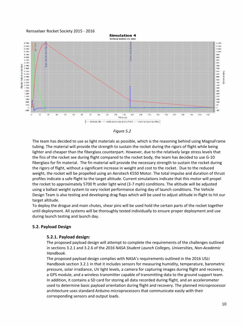
Figure 5.2
The team has decided to use as light materials as possible, which is the reasoning behind using MagnaFrame tubing. The material will provide the strength to sustain the rocket during the rigors of flight while being lighter and cheaper than the fiberglass counterpart. However, due to the relatively large stress levels that the fins of the rocket see during flight compared to the rocket body, the team has decided to use G-10 fiberglass for fin material. The fin material will provide the necessary strength to sustain the rocket during the rigors of flight, without a significant increase in weight and cost to the rocket. Due to the reduced weight, the rocket will be propelled using an Aerotech K550 Motor. The total impulse and duration of thrust profiles indicate a safe flight to the target altitude. Current simulations indicate that this motor will propel the rocket to approximately 5700 ft under light wind (3-7 mph) conditions. The altitude will be adjusted using a ballast weight system to vary rocket performance during day of launch conditions. The Vehicle Design Team is also testing and developing drag flaps which will be used to adjust altitude in-flight to hit our target altitude. To deploy the drogue and main chutes, shear pins will be used hold the certain parts of the rocket together until deployment. All systems will be thoroughly tested individually to ensure proper deployment and use during launch testing and launch day.
5.2. Payload Design
5.2.1. Payload design: The proposed payload design will attempt to complete the requirements of the challenges outlined in sections 3.2.1 and 3.2.6 of the 2016 NASA Student Launch Colleges, Universities, Non-Academic Handbook. The proposed payload design complies with NASA’s requirements outlined in the 2016 USLI Handbook section 3.2.1 in that it includes sensors for measuring humidity, temperature, barometric pressure, solar irradiance, UV light levels, a camera for capturing images during flight and recovery, a GPS module, and a wireless transmitter capable of transmitting data to the ground support team. In addition, it contains a SD card for storing all data recorded during flight, and an accelerometer used to determine basic payload orientation during flight and recovery. The planned microprocessor architecture uses standard Arduino microprocessors that communicate easily with their corresponding sensors and output loads.
Rensselaer Rocket Society 2015 - 2016
11
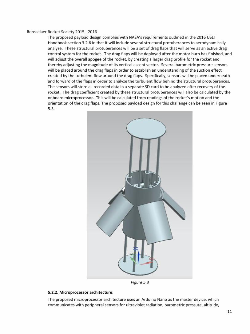
The proposed payload design complies with NASA’s requirements outlined in the 2016 USLI Handbook section 3.2.6 in that it will include several structural protuberances to aerodynamically analyze. These structural protuberances will be a set of drag flaps that will serve as an active drag control system for the rocket. The drag flaps will be deployed after the motor burn has finished, and will adjust the overall apogee of the rocket, by creating a larger drag profile for the rocket and thereby adjusting the magnitude of its vertical ascent vector. Several barometric pressure sensors will be placed around the drag flaps in order to establish an understanding of the suction effect created by the turbulent flow around the drag flaps. Specifically, sensors will be placed underneath and forward of the flaps in order to analyze the turbulent flow behind the structural protuberances. The sensors will store all recorded data in a separate SD card to be analyzed after recovery of the rocket. The drag coefficient created by these structural protuberances will also be calculated by the onboard microprocessor. This will be calculated from readings of the rocket’s motion and the orientation of the drag flaps. The proposed payload design for this challenge can be seen in Figure 5.3.
Figure 5.3
5.2.2. Microprocessor architecture:
The proposed microprocessor architecture uses an Arduino Nano as the master device, which communicates with peripheral sensors for ultraviolet radiation, barometric pressure, altitude,
Rensselaer Rocket Society 2015 - 2016
12
humidity, and temperature. It also controls two 728x488 cameras, a pyranometer, and an SD card. Data collected from the sensors is logged to an SD card and are transmitted to the ground station along with images from the cameras. The Arduino also controls a GPS module, which transmits positional data to the ground station. Additional sensor inputs are used by the Arduino to adjust the drag flap system in order to maintain the correct vertical ascent.
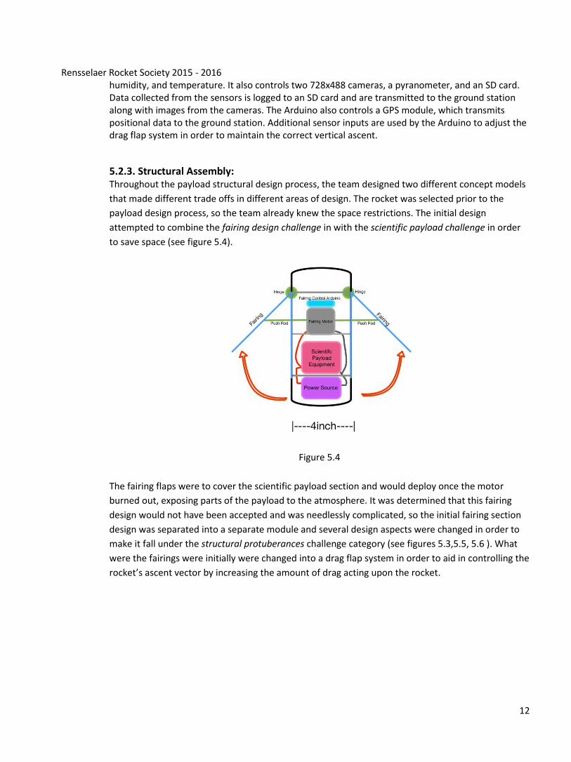
5.2.3. Structural Assembly: Throughout the payload structural design process, the team designed two different concept models
that made different trade offs in different areas of design. The rocket was selected prior to the
payload design process, so the team already knew the space restrictions. The initial design
attempted to combine the fairing design challenge in with the scientific payload challenge in order
to save space (see figure 5.4).
Figure 5.4
The fairing flaps were to cover the scientific payload section and would deploy once the motor
burned out, exposing parts of the payload to the atmosphere. It was determined that this fairing
design would not have been accepted and was needlessly complicated, so the initial fairing section
design was separated into a separate module and several design aspects were changed in order to
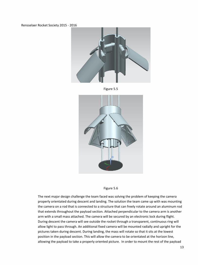
make it fall under the structural protuberances challenge category (see figures 5.3,5.5, 5.6 ). What
were the fairings were initially were changed into a drag flap system in order to aid in controlling the
rocket’s ascent vector by increasing the amount of drag acting upon the rocket.
Rensselaer Rocket Society 2015 - 2016
13
Figure 5.5
Figure 5.6
The next major design challenge the team faced was solving the problem of keeping the camera
properly orientated during descent and landing. The solution the team came up with was mounting
the camera on a rod that is connected to a structure that can freely rotate around an aluminum rod
that extends throughout the payload section. Attached perpendicular to the camera arm is another
arm with a small mass attached. The camera will be secured by an electronic lock during flight.
During descent the camera will see outside the rocket through a transparent, continuous ring will
allow light to pass through. An additional fixed camera will be mounted radially and upright for the
pictures taken during descent. During landing, the mass will rotate so that it sits at the lowest
position in the payload section. This will allow the camera to be orientated at the horizon line,
allowing the payload to take a properly oriented picture. In order to mount the rest of the payload
Rensselaer Rocket Society 2015 - 2016
14
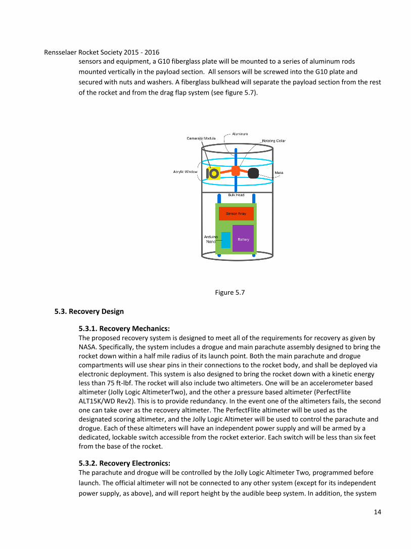
sensors and equipment, a G10 fiberglass plate will be mounted to a series of aluminum rods
mounted vertically in the payload section. All sensors will be screwed into the G10 plate and
secured with nuts and washers. A fiberglass bulkhead will separate the payload section from the rest
of the rocket and from the drag flap system (see figure 5.7).
Figure 5.7
5.3. Recovery Design
5.3.1. Recovery Mechanics: The proposed recovery system is designed to meet all of the requirements for recovery as given by NASA. Specifically, the system includes a drogue and main parachute assembly designed to bring the rocket down within a half mile radius of its launch point. Both the main parachute and drogue compartments will use shear pins in their connections to the rocket body, and shall be deployed via electronic deployment. This system is also designed to bring the rocket down with a kinetic energy less than 75 ft-lbf. The rocket will also include two altimeters. One will be an accelerometer based altimeter (Jolly Logic AltimeterTwo), and the other a pressure based altimeter (PerfectFlite ALT15K/WD Rev2). This is to provide redundancy. In the event one of the altimeters fails, the second one can take over as the recovery altimeter. The PerfectFlite altimeter will be used as the designated scoring altimeter, and the Jolly Logic Altimeter will be used to control the parachute and drogue. Each of these altimeters will have an independent power supply and will be armed by a dedicated, lockable switch accessible from the rocket exterior. Each switch will be less than six feet from the base of the rocket.
5.3.2. Recovery Electronics: The parachute and drogue will be controlled by the Jolly Logic Altimeter Two, programmed before
launch. The official altimeter will not be connected to any other system (except for its independent
power supply, as above), and will report height by the audible beep system. In addition, the system
Rensselaer Rocket Society 2015 - 2016
15
will include an XBEE radio transmitter for easy recovery of the rocket. In addition, any rocket section
or payload component that lands untethered to the launch vehicle shall have its own dedicated
XBEE radio transmitter, as above. All radio transmitters shall be fully functional during the official
flight at the competition launch site. All electronics will be able to stand on the pad for up to one
hour without failing or disarming, and will have a power supply sufficient to supply this. The
compartment containing the recovery system electronics shall not contain any other radio
frequency transmitting device and/or magnetic wave generating device. In addition, all of the
recovery electronics shall be shielded from all the other onboard electronics, radio transmitting
devices, magnetic wave generating device, or any other device that could adversely affect the
proper operation of the recovery system electronics.
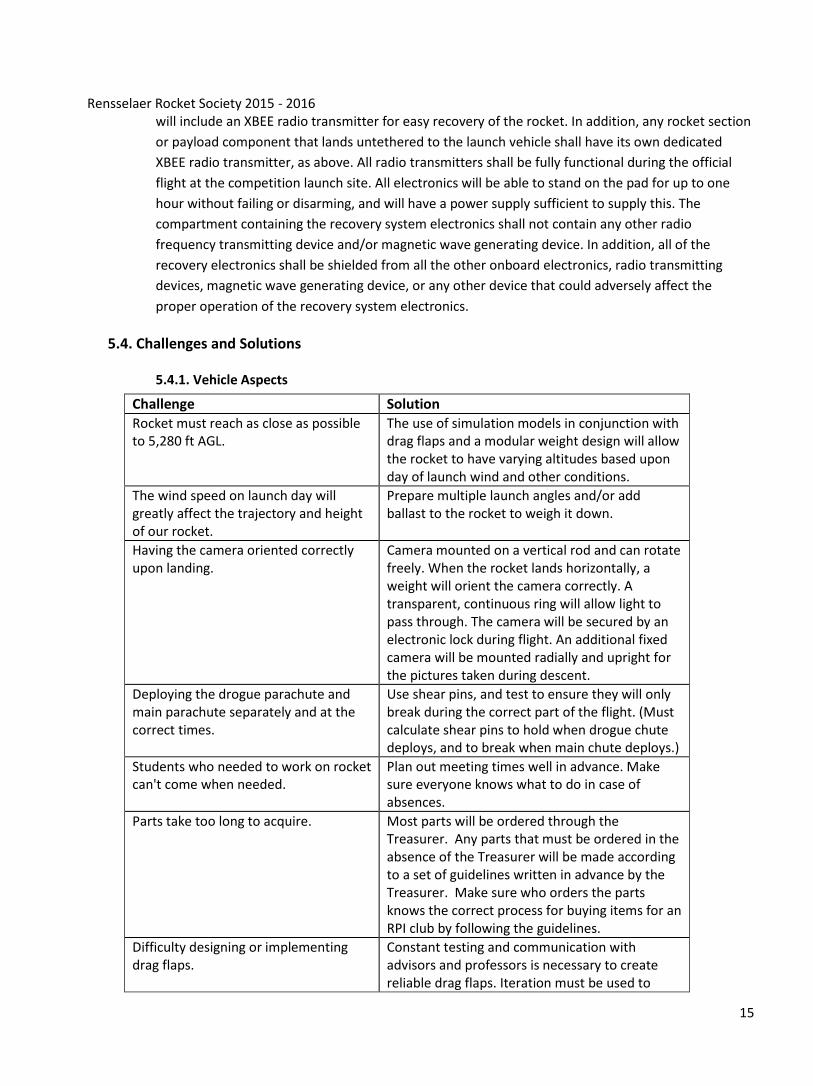
5.4. Challenges and Solutions
5.4.1. Vehicle Aspects
Challenge Solution
Rocket must reach as close as possible to 5,280 ft AGL.
The use of simulation models in conjunction with drag flaps and a modular weight design will allow the rocket to have varying altitudes based upon day of launch wind and other conditions.
The wind speed on launch day will greatly affect the trajectory and height of our rocket.
Prepare multiple launch angles and/or add ballast to the rocket to weigh it down.
Having the camera oriented correctly upon landing.
Camera mounted on a vertical rod and can rotate freely. When the rocket lands horizontally, a weight will orient the camera correctly. A transparent, continuous ring will allow light to pass through. The camera will be secured by an electronic lock during flight. An additional fixed camera will be mounted radially and upright for the pictures taken during descent.
Deploying the drogue parachute and main parachute separately and at the correct times.
Use shear pins, and test to ensure they will only break during the correct part of the flight. (Must calculate shear pins to hold when drogue chute deploys, and to break when main chute deploys.)
Students who needed to work on rocket can't come when needed.
Plan out meeting times well in advance. Make sure everyone knows what to do in case of absences.
Parts take too long to acquire. Most parts will be ordered through the Treasurer. Any parts that must be ordered in the absence of the Treasurer will be made according to a set of guidelines written in advance by the Treasurer. Make sure who orders the parts knows the correct process for buying items for an RPI club by following the guidelines.
Difficulty designing or implementing drag flaps.
Constant testing and communication with advisors and professors is necessary to create reliable drag flaps. Iteration must be used to
Rensselaer Rocket Society 2015 - 2016
16
develop a working system.
Successfully recover all portions of the rocket.
A dual-deployment recovery system will be employed as per competition rules in order to maximize survivability of the rocket body and payload and minimize drift from launch location. Parachutes will be designed within parameters ensuring a landing at speeds which the components of the rocket will be designed to tolerate. Additionally, an electronic transmitter, either GPS or radio based, will be used to locate the rocket upon landing.
6. Educational Engagement
6.1. Soda Bottle Rockets and Open House The RRS will organize an educational day where the RRS will teach incoming Rensselaer freshmen students about rocketry. We will use water rockets, as explained at this link . The launch pad will be built beforehand. First, there will be a preliminary discussion to educate the students about basics of rocketry and give instruction for building a soda bottle rocket. Soda bottles, cardboard, and other materials for constructing the rockets will be provided to the students. Students will divide into teams to design and construct their own rockets. A construction period will ensue, and then the rockets will be launched. After the launches, there will be a concluding discussion session reflecting on what the students observed and learned. This discussion will be held at the RRS meeting and design room. This will also serve as an open house for the Rensselaer community. Following the soda bottle rockets discussion, attendees will be presented a short info session about general rocketry, the Rensselaer Rocket Society and the RRS’s rocket. General rocketry will include history of rocketry, types of rockets, and modern and future uses of rockets. The presentation of the RRS will introduce the members of the team and briefly discuss some individuals’ majors and interests. A presentation will be made introducing the RRS’s rocket including specifications, an overview of the objectives for the rocket, and an analysis of construction of the rocket.
6.2. Test Launch Rensselaer students and local high school students will be invited to see the test launch of the RRS’s rocket.
They will be able to observe launch procedures and will learn about rocketry safety and its importance. After
the launch RRS will hold a brief discussion about the science of rocketry.
6.3. Girl Scouts Egg-Drop
The RRS will contact a local girl scouts troop and organize an educational day where RRS will hold a
presentation on recovery systems for payloads that are released from high altitudes. The RRS will proceed
to discuss different adaptations of these real-life recovery systems to an egg-drop competition. Cardboard,
paper towels, plastic cups, and other materials will be provided for the girl scouts to design and build a
container or parachute to protect a raw egg during a drop from a tall platform. After a construction period,
the RRS will assist the girl scouts in testing their egg protection system with each individual dropping their
egg from a tall walkway onto a tarp below. After the drop, the RRS will host a brief discussion with the girl
scouts, their parents, and the scout troop leaders.
Rensselaer Rocket Society 2015 - 2016
17
6.4. Girl Scouts Model Rocket Launch
The RRS will contact a local Girl Scout troop and organize an educational event where RRS will hold a
presentation on large scale and model rocketry. The Girl Scouts will be introduced to rocket structures that
will be mirrored in a construction of small scale, individual rockets. Model rocket kits and additional
construction materials will be provided for each girl scout and their parent to build a rocket. From there, the
group will travel to a clear, open field that will serve as a safe launch site. Each rocket will be launched on a
launch pad provided in the rocket kit by the RRS and the girl scouts troop leader. After the launch, a
discussion will be held on rocket design and how the girl scouts might improve their rocket construction in a
future launch.
Put in boy scouts?
Mention getting woman into engineering?
7. Project Plan
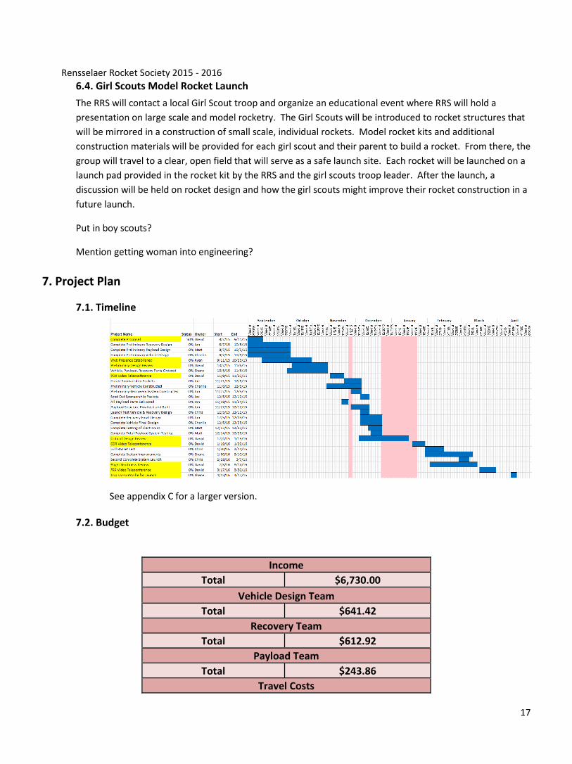
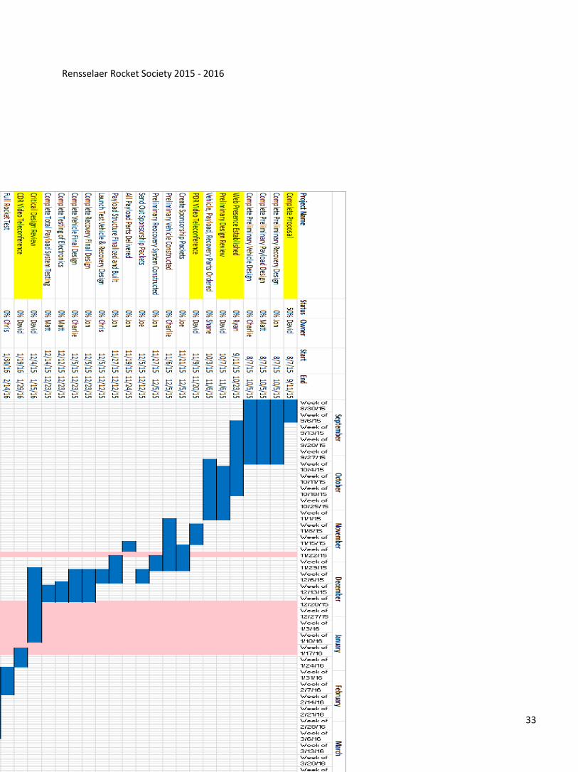
7.1. Timeline
See appendix C for a larger version.
7.2. Budget
Income
Total $6,730.00
Vehicle Design Team
Total $641.42
Recovery Team
Total $612.92
Payload Team
Total $243.86
Travel Costs
Rensselaer Rocket Society 2015 - 2016
18
Total $5,070.00
Totals
Total Income $6,730.00
Total Expenditures $6,568.20
Total Budget $161.80
See Appendix B for a more detailed budget.
7.3 Additional Community Support
The RRS plans to establish partnerships both through Mr. Sicker and the RPI community. Mr. Sicker is able to
provide much of the needed expertise to guide the design and construction of the rocket and payload. In
addition, the RRS will be able to launch small and large scale models of the rocket through METRA and
CTRA-NARCON, organizations with which Mr. Sicker is affiliated. The plan will also include efforts to work
together with other clubs at RPI, both for technical help and sponsorship. The RRS has plans to sponsor a
movie through UPAC Cinema, a student-run organization on campus, and to receive technical help from
organizations with a focus on mechanical engineering and electronics. The RRS also plans to work with the
RPI School of Engineering to schedule an appointment to use a wind tunnel on campus for physical testing of
the drag flap system.
7.4 Plan for Sustainability
In order for the RRS to continue to be sustainable, we actively recruit new members every fall semester
through on-campus events like “Soda Bottle Rockets.” After joining, new members are taught the basics of
rocket design and construction by building smaller scale rockets in teams. When they are finished, they can
engage in larger projects such as the NASA USLI. Financially, the RRS is sustained by membership dues,
funding from the Department of Mechanical, Aerospace, and Nuclear Engineering, and donations from
alumni. The RRS also has plans to continue partnerships with local Girl Scout troops and middle school
students visiting RPI this fall. In this way, the RRS hopes to maintain a legacy of teams in rocketry at RPI that
are able to engage the community as well.
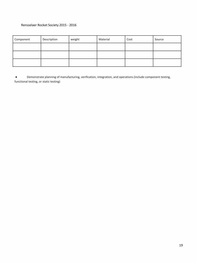
● Demonstrate an understanding of all components needed to complete the project and how risks/delays impact the
project.
Components
Rensselaer Rocket Society 2015 - 2016
19
Component Description weight Material Cost Source
● Demonstrate planning of manufacturing, verification, integration, and operations (include component testing,
functional testing, or static testing)

Rensselaer Rocket Society 2015 - 2016
20
Appendix

Rensselaer Rocket Society 2015 - 2016
21

Rensselaer Rocket Society 2015 - 2016
22
Appendix A: Resumes
Rensselaer Rocket Society 2015 - 2016
23
Rensselaer Rocket Society 2015 - 2016
24
Rensselaer Rocket Society 2015 - 2016
25
Joseph Hatch
22 Blue Rock Hill Lane • N. Attleboro, MA 02760 • 508.298.2827 • [email protected]
Objective To obtain an aerospace engineering internship or co-op during the spring and summer of 2016 to help me prepare for industry readiness.
Education Rensselaer Polytechnic Institute Bachelor of Science in Aerospace Engineering, Expected December 2016 • GPA (Major): 3.7 •GPA (Overall): 3.5 • Dean’s List – 4/4 semesters Relevant Coursework: Aerodynamics, Aerospace Structures and Materials, Numerical Computing, Thermal and Fluids Engineering, Modeling and Control of Dynamic Systems, Fundamentals of Flight, Introduction to Engineering Design and Professional Development, Strength of Materials, Beginning C Programming for Engineers, Engineering Processes, Engineering Graphics and CAD
Engineering Experience
Center for Flow Physics and Control, research assistant Summer 2015 - Present ● Projects assisted:
Characterization of Transitional Boundary Layer on a Flat Plate (Northrop-Grumman) – Burak Tuna, Ph.D. Interactions of a Dynamic Vortex Generator with a Cross-flow (Boeing) – Erica Cruz, Ph.D. candidate Manufacturing of Synthetic Jet Actuators (Boeing) – Kevin Housley, Ph.D. candidate
● Assisted in the setup of several laboratory experiments, including in a large-scale, subsonic wind tunnel ● Developed and manufactured active flow control actuators Rocket Club Large Scale Project 2014-15 ● Leader of Recovery Team, responsible for the design and execution of deployment of parachutes and a
safe recovery ● Two launches planned to launch the 12 foot, 60 pound rocket to 10,000 and 20,000 feet
● Flying GPS, altitude, pressure, humidity, temperature, gyroscopic, and accelerometer sensors; along with a camera to document the flight
Filtration System for Southeast Asian Families – Engineering Design Project Spring 2015 ● Collaborated with six other students in a multidisciplinary design project ● Wrote an 80-page technical report documenting planned product ● Designed and tested a cost-effective filtration system that could filter particulates, bio contaminants and
arsenic from river water to produce potable water ● Personally focused on the arsenic filter and the integration of all of the subsystems
Skills
Computer: MATLAB, Siemens NX CAD (Unigraphics), Minitab Statistical Software, Microsoft Office Laboratory: Particle Image Velocimetry (PIV), Constant Temperature Anemometry (CTA) with a Hot Wire,
general machine shop skills Certifications: Tripoli Rocketry Association – Level 1 Certified
Leadership Experience Treasurer, Rensselaer Rocket Society (RRS) Spring 2014 - Present ● In charge of budgeting, corporate sponsorships, and allocation of funds for the club ● Actively engaging new members and networking with other campus clubs to produce revenue
Rensselaer Rocket Society 2015 - 2016
26
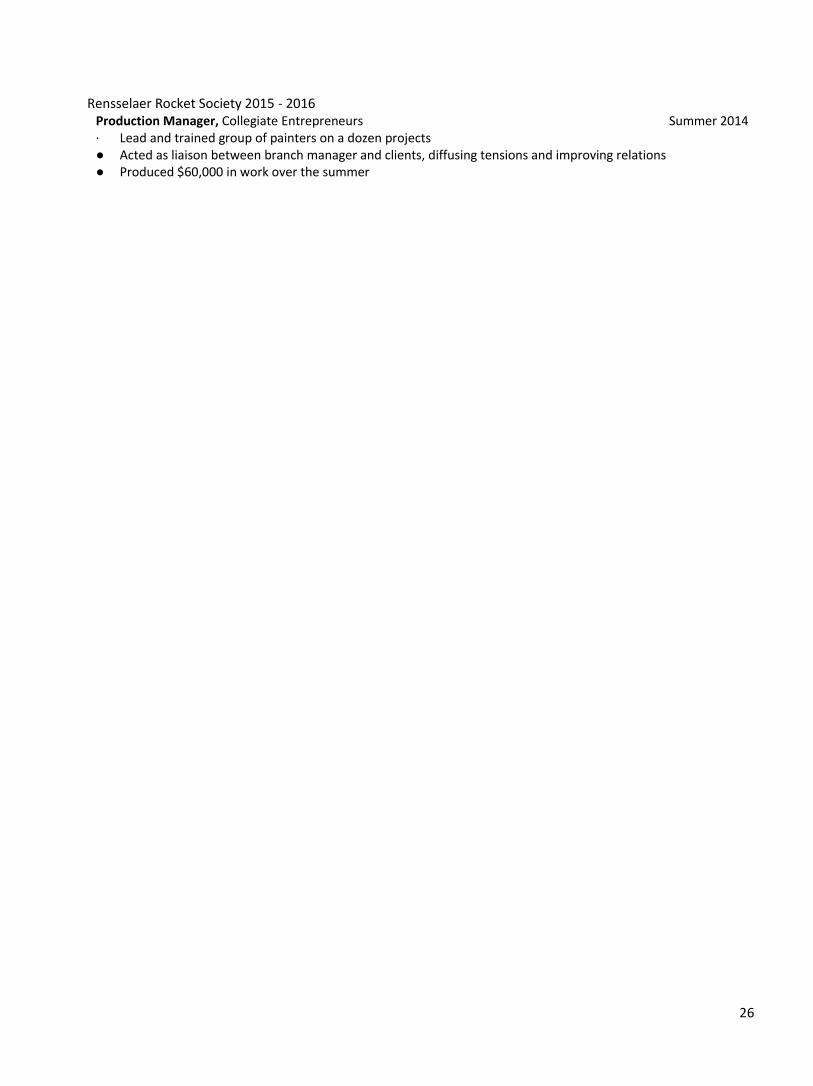
Production Manager, Collegiate Entrepreneurs Summer 2014 ∙ Lead and trained group of painters on a dozen projects ● Acted as liaison between branch manager and clients, diffusing tensions and improving relations ● Produced $60,000 in work over the summer
Rensselaer Rocket Society 2015 - 2016
27
Rensselaer Rocket Society 2015 - 2016
28
Rensselaer Rocket Society 2015 - 2016
29
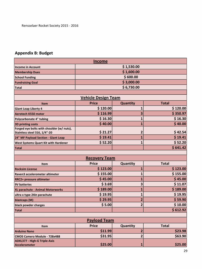
Appendix B: Budget
Income
Income in Account $ 1,530.00
Membership Dues $ 1,600.00
School Funding $ 600.00
Fundraising Goal $ 3,000.00
Total $ 6,730.00
Vehicle Design Team
Item Price Quantity Total
Giant Leap Liberty 4 $ 120.00 1 $ 120.00
Aerotech K550 motor $ 116.99 3 $ 350.97
Polycarbonate 4" tubing $ 16.30 1 $ 16.30
3D printing costs $ 40.00 1 $ 40.00 Forged eye bolts with shoulder (w/ nuts), Stainless steel 316, 1/4"-20 $ 21.27 2 $ 42.54
24" MF Payload Section - Giant Leap $ 19.41 1 $ 19.41
West Systems Quart Kit with Hardener $ 52.20 1 $ 52.20
Total $ 641.42
Recovery Team
Item Price Quantity Total
Rocksim License $ 123.00 1 $ 123.00
Raven3 accelerometer altimeter $ 155.00 1 $ 155.00
RRC2+ pressure altimeter $ 45.00 1 $ 45.00
9V batteries $ 3.69 3 $ 11.07
XL parachute - Animal Motorworks $ 189.00 1 $ 189.00
ultra x type 24in parachute $ 19.95 1 $ 19.95
blastcaps (M) $ 29.95 2 $ 59.90
black powder charges $ 5.00 2 $ 10.00
Total $ 612.92
Payload Team
Item Price Quantity Total
Arduino Nano $11.99 2 $23.98
CMOS Camera Module - 728x488 $31.95 2 $63.90 ADXL377 - High-G Triple-Axis Accelerometer $25.00 1 $25.00
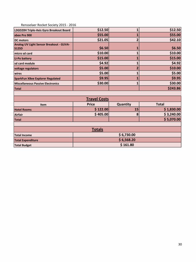
Rensselaer Rocket Society 2015 - 2016
30
L3GD20H Triple-Axis Gyro Breakout Board $12.50 1 $12.50
xbee Pro 900 $55.00 1 $55.00
DC motors $21.05 2 $42.10 Analog UV Light Sensor Breakout - GUVA-S12SD $6.50 1 $6.50
micro sd card $10.00 1 $10.00
Li-Po battery $15.00 1 $15.00
sd card module $4.92 1 $4.92
voltage regulators $5.00 2 $10.00
wires $5.00 1 $5.00
SparkFun XBee Explorer Regulated $9.95 1 $9.95
Miscellaneous Passive Electronics $30.00 1 $30.00
Total $243.86
Travel Costs
Item Price Quantity Total
Hotel Rooms $ 122.00 15 $ 1,830.00
Airfair $ 405.00 8 $ 3,240.00
Total $ 5,070.00
Totals
Total Income $ 6,730.00
Total Expenditure $ 6,568.20
Total Budget $ 161.80

Rensselaer Rocket Society 2015 - 2016
31

Rensselaer Rocket Society 2015 - 2016
32
Appendix C: Timeline
Rensselaer Rocket Society 2015 - 2016
33
Rensselaer Rocket Society 2015 - 2016
34
Appendix D: FAA Regulations
Code of Federal Regulations Title 14: Aeronautics and Space Effective date: February 2, 2009 PART 101—MOORED BALLOONS, KITES, UNMANNED ROCKETS AND UNMANNED FREE BALLOONS Subpart C—Unmanned Rockets § 101.21 Applicability. (a) This subpart applies to operating unmanned rockets. However, a person operating an unmanned rocket within a restricted area must comply with §101.25(b)(7)(ii) and with any additional limitations imposed by the using or controlling agency. (b) A person operating an unmanned rocket other than an amateur rocket as defined in §1.1 of this chapter must comply with 14 CFR Chapter III. [Doc. No. FAA–2007–27390, 73 FR 73781, Dec. 4, 2008] § 101.22 Definitions. The following definitions apply to this subpart: (a) Class 1—Model Rocket means an amateur rocket that: (1) Uses no more than 125 grams (4.4 ounces) of propellant; (2) Uses a slow-burning propellant; (3) Is made of paper, wood, or breakable plastic; (4) Contains no substantial metal parts; and (5) Weighs no more than 1,500 grams (53 ounces), including the propellant. (b) Class 2—High-Power Rocket means an amateur rocket other than a model rocket that is propelled by a motor or motors having a combined total impulse of 40,960 Newton-seconds (9,208 pound-seconds) or less. (c) Class 3—Advanced High-Power Rocket means an amateur rocket other than a model rocket or high-power rocket. [Doc. No. FAA–2007–27390, 73 FR 73781, Dec. 4, 2008] § 101.23 General operating limitations. (a) You must operate an amateur rocket in such a manner that it: (1) Is launched on a suborbital trajectory; (2) When launched, must not cross into the territory of a foreign country unless an agreement is in place between the United States and the country of concern; (3) Is unmanned; and (4) Does not create a hazard to persons, property, or other aircraft. (b) The FAA may specify additional operating limitations necessary to ensure that air traffic is not adversely affected, and public safety is not jeopardized. [Doc. No. FAA–2007–27390, 73 FR 73781, Dec. 4, 2008] § 101.25 Operating limitations for Class 2—High-Power Rockets. (a) You must comply with the General Operating Limitations of §101.23. (b) In addition, you must not operate a Class 2—High-Power Rocket— (1) At any altitude where clouds or obscuring phenomena of more than five-tenths coverage prevails; (2) At any altitude where the horizontal visibility is less than five miles; (3) Into any cloud; (4) Between sunset and sunrise without prior authorization from the FAA; (5) Within 8 kilometers (5 statute miles) of any airport boundary without prior authorization from the FAA; (6) In controlled airspace without prior authorization from the FAA; (7) Unless you observe the greater of the following separation distances from any person or property that is not associated with the operations applies: (i) Not less than one-quarter the maximum expected altitude; (ii) 457 meters (1,500 ft.); (8) Unless a person at least eighteen years old is present, is charged with ensuring the safety of the operation, and has final approval authority for initiating high-power rocket flight; and (9) Unless reasonable precautions are provided to report and control a fire caused by rocket activities. [Doc. No. FAA–2007–27390, 73 FR 73781, Dec. 4, 2008] § 101.26 Operating limitations for Class 3—Advanced High-Power Rockets. You must comply with: (a) The General Operating Limitations of §101.23; (b) The operating limitations contained in §101.25; (c) Any other operating limitations for Class 3—Advanced High-Power Rockets prescribed by the FAA that are necessary to ensure that air traffic is not adversely affected, and public safety is not jeopardized. [Doc. No. FAA–2007–27390, 73 FR 73781, Dec. 4, 2008]
Rensselaer Rocket Society 2015 - 2016
35
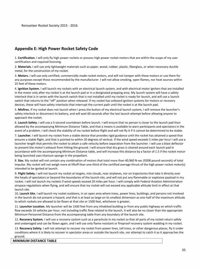
Appendix E: High Power Rocket Safety Code 1. Certification. I will only fly high power rockets or possess high power rocket motors that are within the scope of my user certification and required licensing.
2. Materials. I will use only lightweight materials such as paper, wood, rubber, plastic, fiberglass, or when necessary ductile metal, for the construction of my rocket.
3. Motors. I will use only certified, commercially made rocket motors, and will not tamper with these motors or use them for any purposes except those recommended by the manufacturer. I will not allow smoking, open flames, nor heat sources within 25 feet of these motors.
4. Ignition System. I will launch my rockets with an electrical launch system, and with electrical motor igniters that are installed in the motor only after my rocket is at the launch pad or in a designated prepping area. My launch system will have a safety interlock that is in series with the launch switch that is not installed until my rocket is ready for launch, and will use a launch switch that returns to the "off" position when released. If my rocket has onboard ignition systems for motors or recovery devices, these will have safety interlocks that interrupt the current path until the rocket is at the launch pad.
5. Misfires. If my rocket does not launch when I press the button of my electrical launch system, I will remove the launcher's safety interlock or disconnect its battery, and will wait 60 seconds after the last launch attempt before allowing anyone to approach the rocket.
6. Launch Safety. I will use a 5-second countdown before launch. I will ensure that no person is closer to the launch pad than allowed by the accompanying Minimum Distance Table, and that a means is available to warn participants and spectators in the event of a problem. I will check the stability of my rocket before flight and will not fly it if it cannot be determined to be stable.
7. Launcher. I will launch my rocket from a stable device that provides rigid guidance until the rocket has attained a speed that ensures a stable flight, and that is pointed to within 20 degrees of vertical. If the wind speed exceeds 5 miles per hour I will use a launcher length that permits the rocket to attain a safe velocity before separation from the launcher. I will use a blast deflector to prevent the motor's exhaust from hitting the ground. I will ensure that dry grass is cleared around each launch pad in accordance with the accompanying Minimum Distance table, and will increase this distance by a factor of 1.5 if the rocket motor being launched uses titanium sponge in the propellant.
8. Size. My rocket will not contain any combination of motors that total more than 40,960 N-sec (9208 pound-seconds) of total impulse. My rocket will not weigh more at liftoff than one-third of the certified average thrust of the high power rocket motor(s) intended to be ignited at launch.
9. Flight Safety. I will not launch my rocket at targets, into clouds, near airplanes, nor on trajectories that take it directly over the heads of spectators or beyond the boundaries of the launch site, and will not put any flammable or explosive payload in my rocket. I will not launch my rockets if wind speeds exceed 20 miles per hour. I will comply with Federal Aviation Administration airspace regulations when flying, and will ensure that my rocket will not exceed any applicable altitude limit in effect at that launch site. 10. Launch Site. I will launch my rocket outdoors, in an open area where trees, power lines, buildings, and persons not involved in the launch do not present a hazard, and that is at least as large on its smallest dimension as one-half of the maximum altitude to which rockets are allowed to be flown at that site or 1500 feet, whichever is greater.
11. Launcher Location. My launcher will be 1500 feet from any inhabited building or from any public highway on which traffic flow exceeds 10 vehicles per hour, not including traffic flow related to the launch. It will also be no closer than the appropriate Minimum Personnel Distance from the accompanying table from any boundary of the launch site.
12. Recovery System. I will use a recovery system such as a parachute in my rocket so that all parts of my rocket return safely and undamaged and can be flown again, and I will use only flame-resistant or fireproof recovery system wadding in my rocket.
13. Recovery Safety. I will not attempt to recover my rocket from power lines, tall trees, or other dangerous places, fly it under conditions where it is likely to recover in spectator areas or outside the launch site, nor attempt to catch it as it approaches the ground.
MINIMUM DISTANCE TABLE
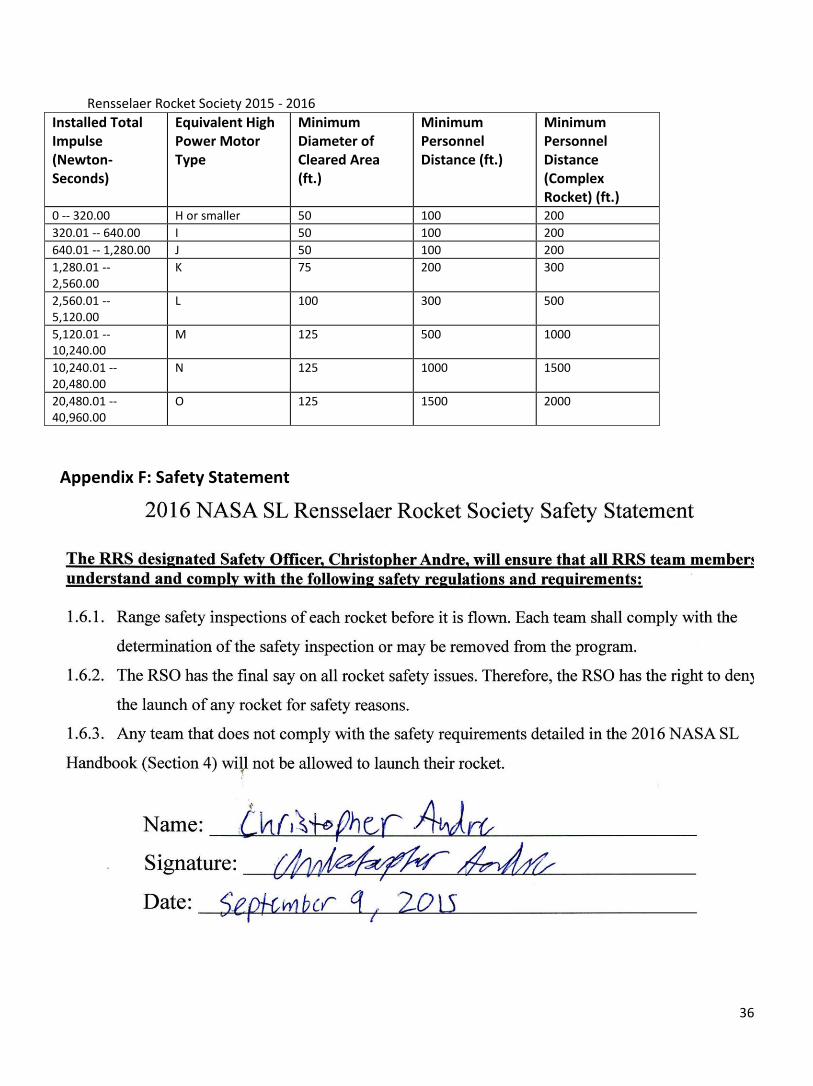
Rensselaer Rocket Society 2015 - 2016
36
Installed Total Impulse (Newton-Seconds)
Equivalent High Power Motor Type
Minimum Diameter of Cleared Area (ft.)
Minimum Personnel Distance (ft.)
Minimum Personnel Distance (Complex Rocket) (ft.)
0 -- 320.00 H or smaller 50 100 200 320.01 -- 640.00 I 50 100 200 640.01 -- 1,280.00 J 50 100 200 1,280.01 -- 2,560.00
K 75 200 300
2,560.01 -- 5,120.00
L 100 300 500
5,120.01 -- 10,240.00
M 125 500 1000
10,240.01 -- 20,480.00
N 125 1000 1500
20,480.01 -- 40,960.00
O 125 1500 2000
Appendix F: Safety Statement
Rensselaer Rocket Society 2015 - 2016
37
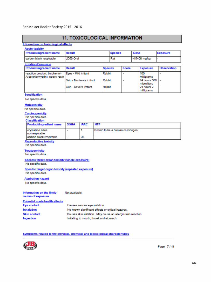
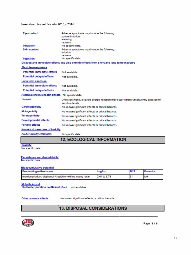
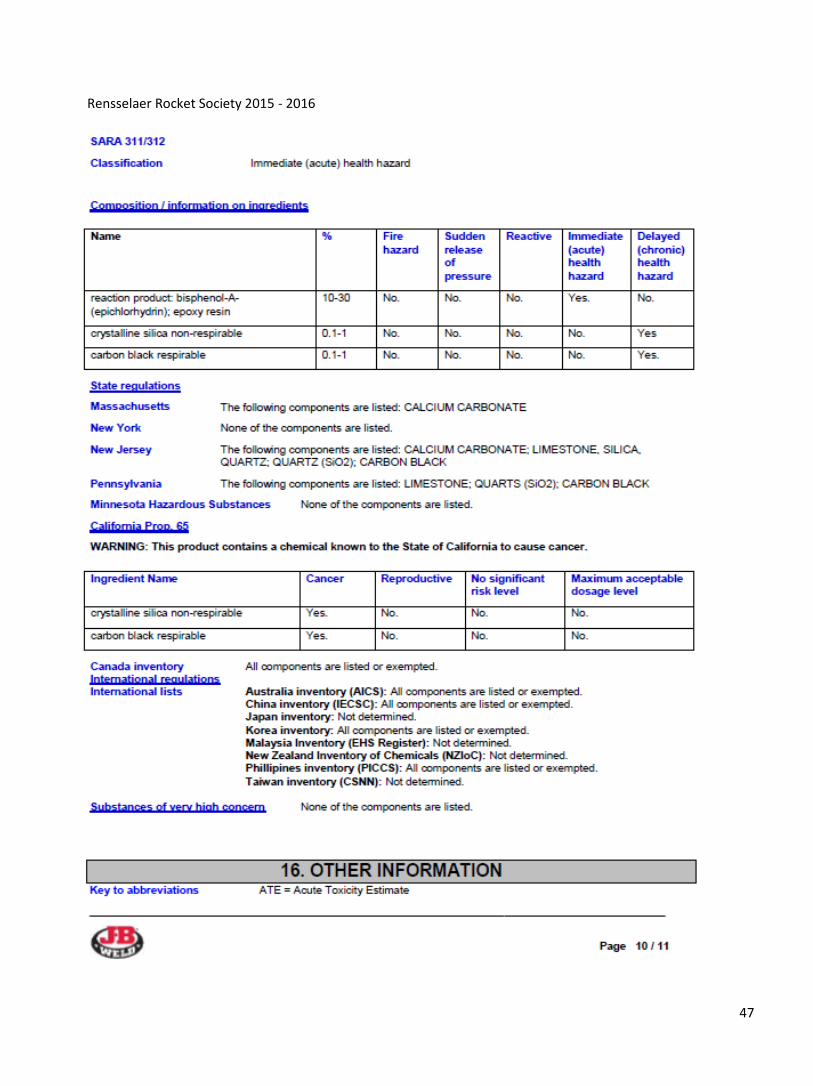
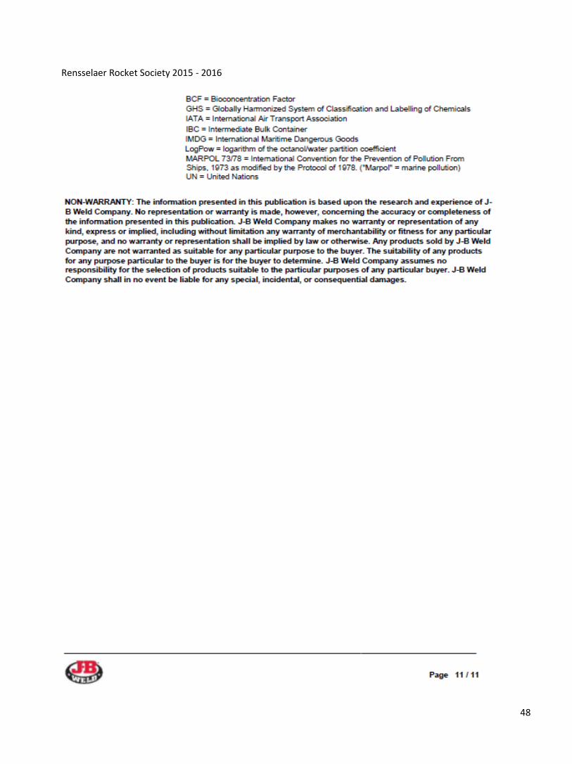
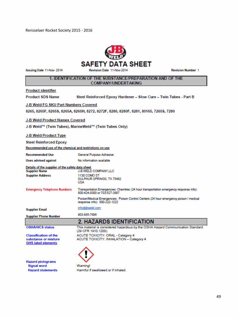
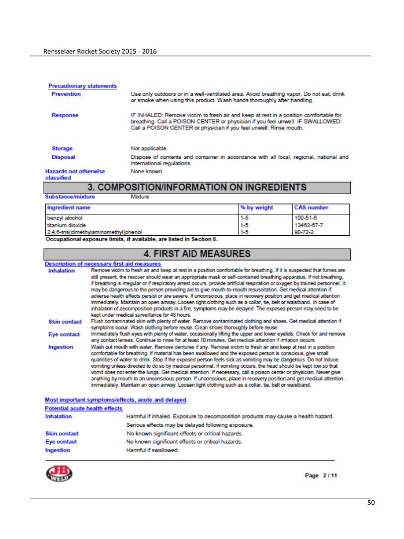
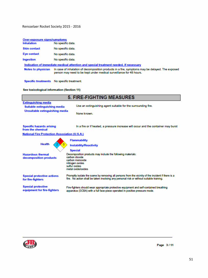
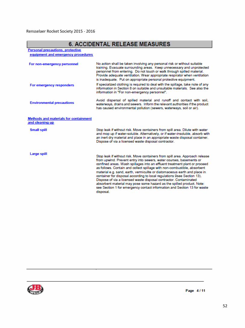
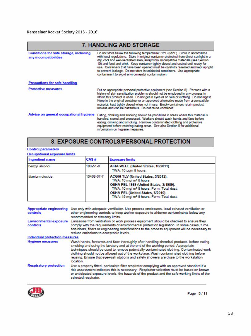
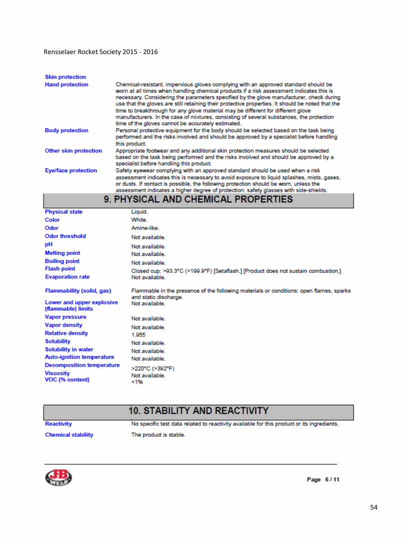
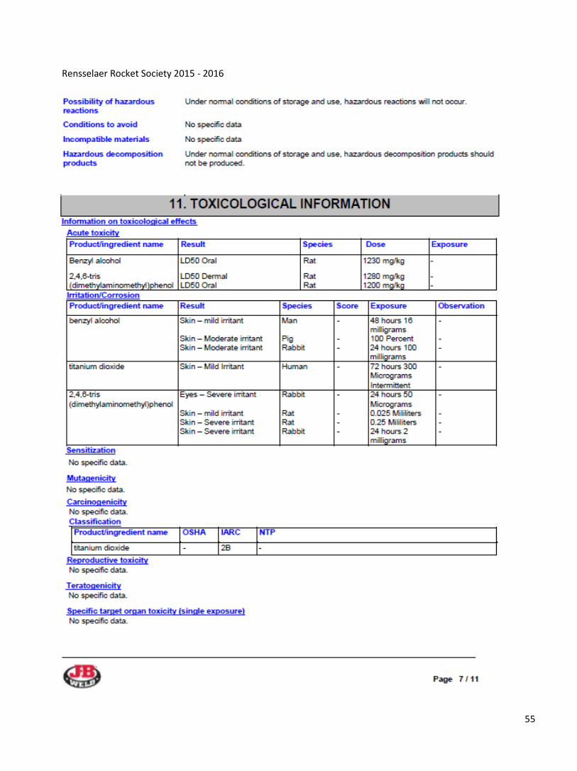
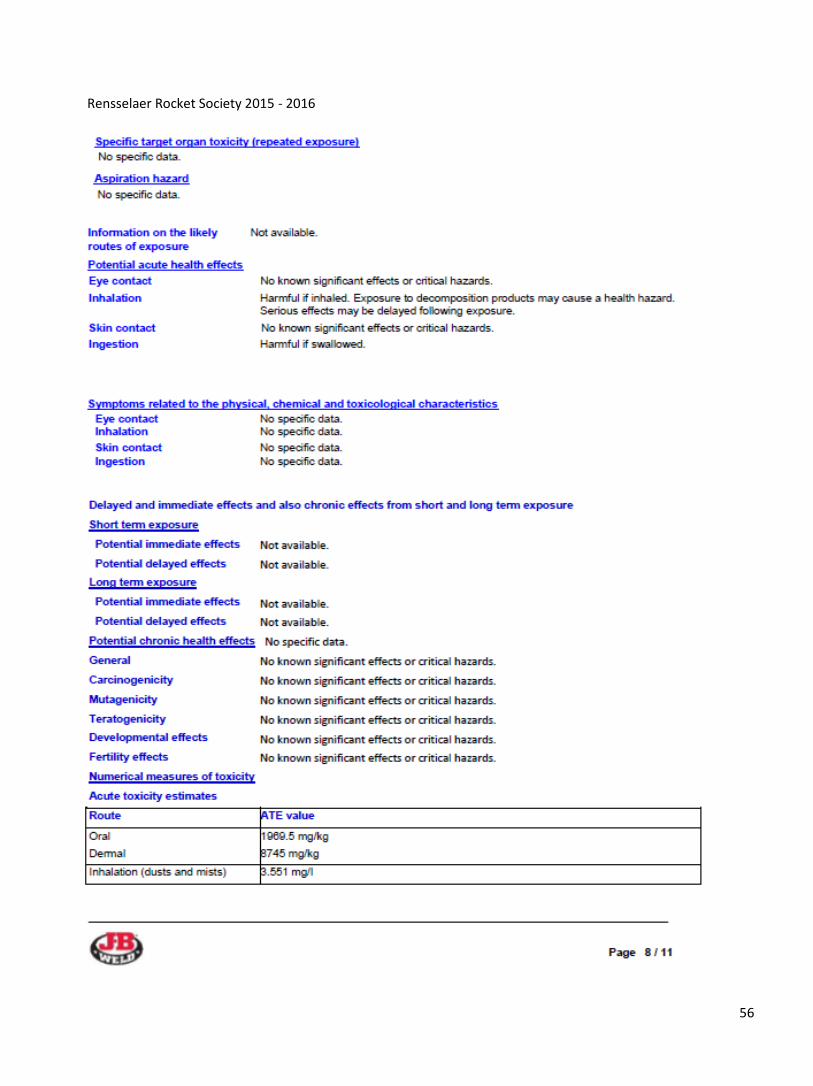
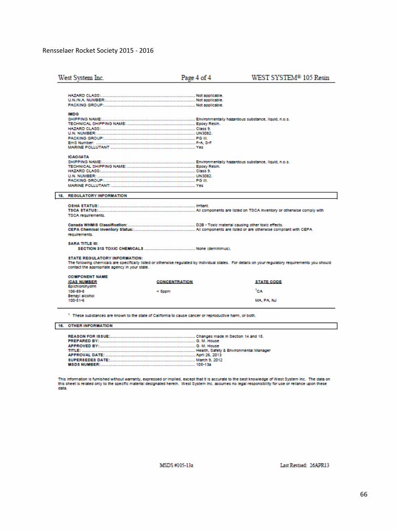
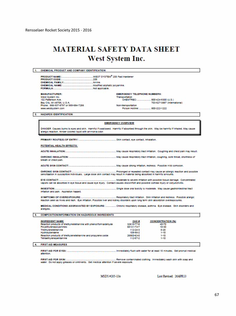
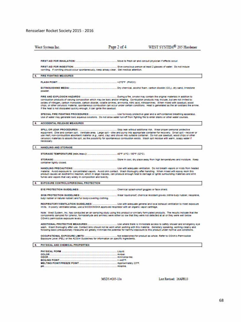
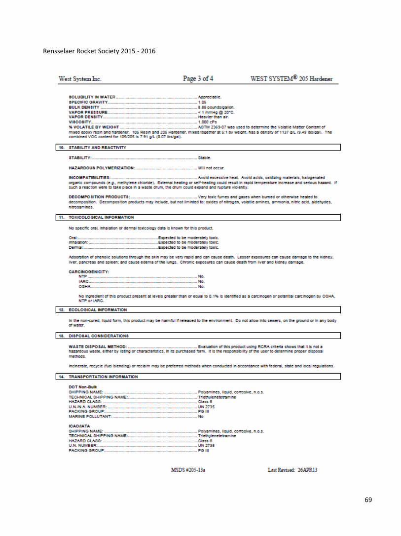
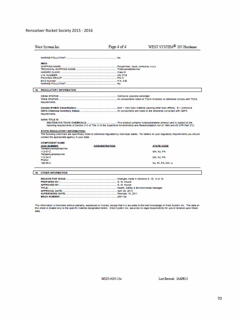
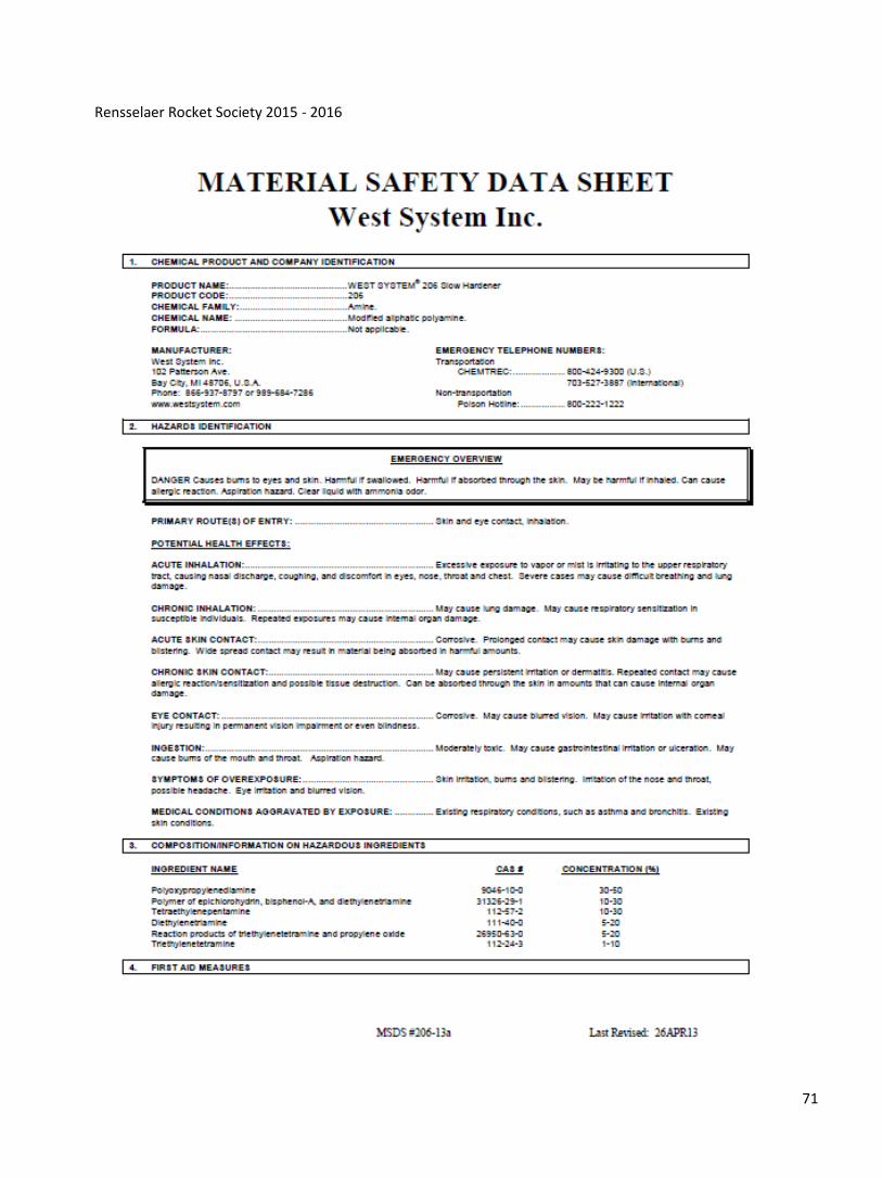
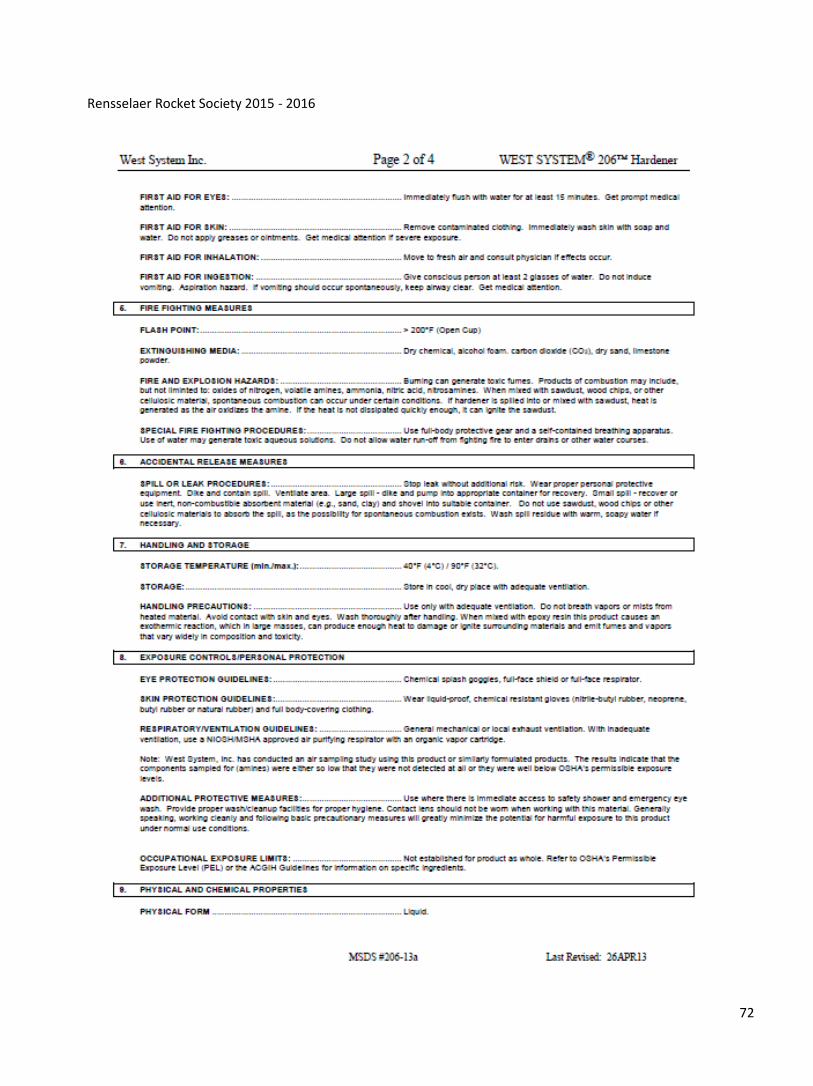
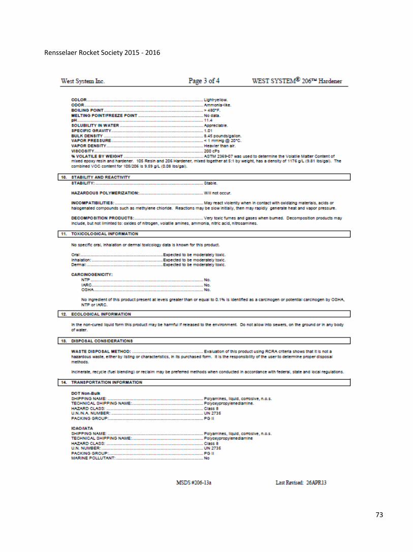
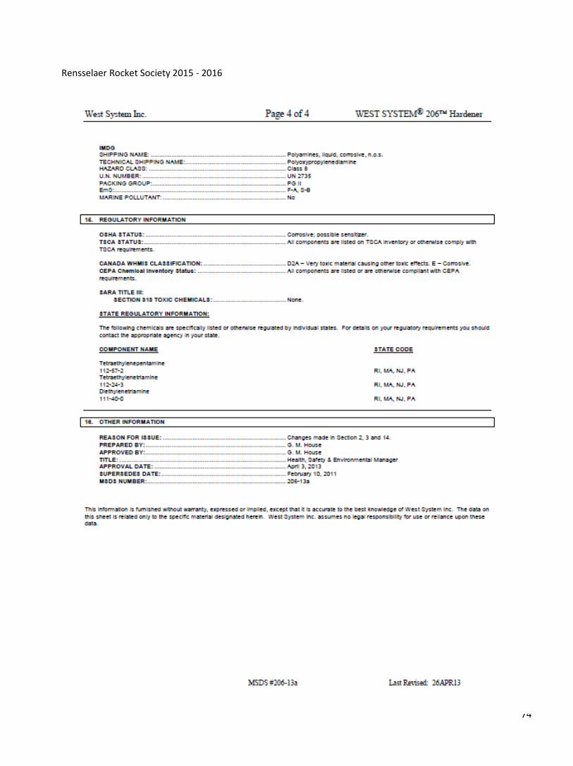
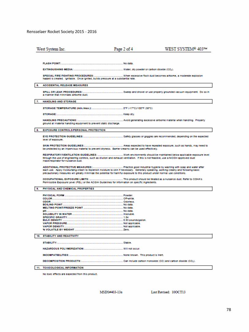
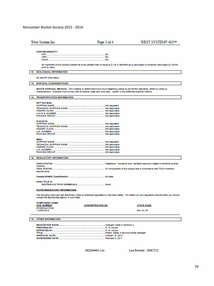
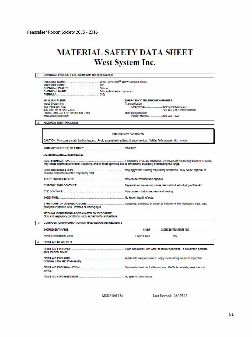
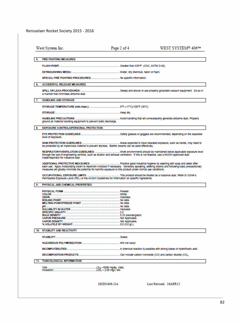
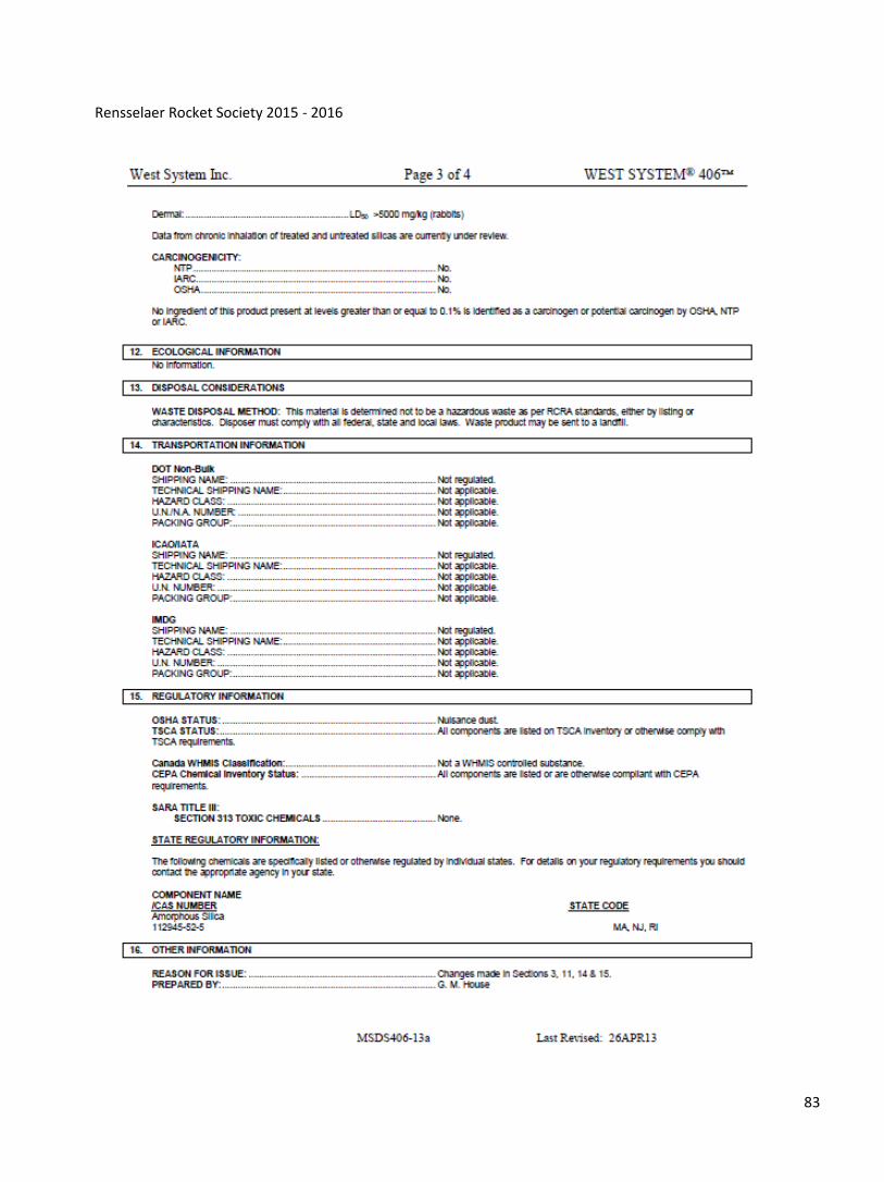
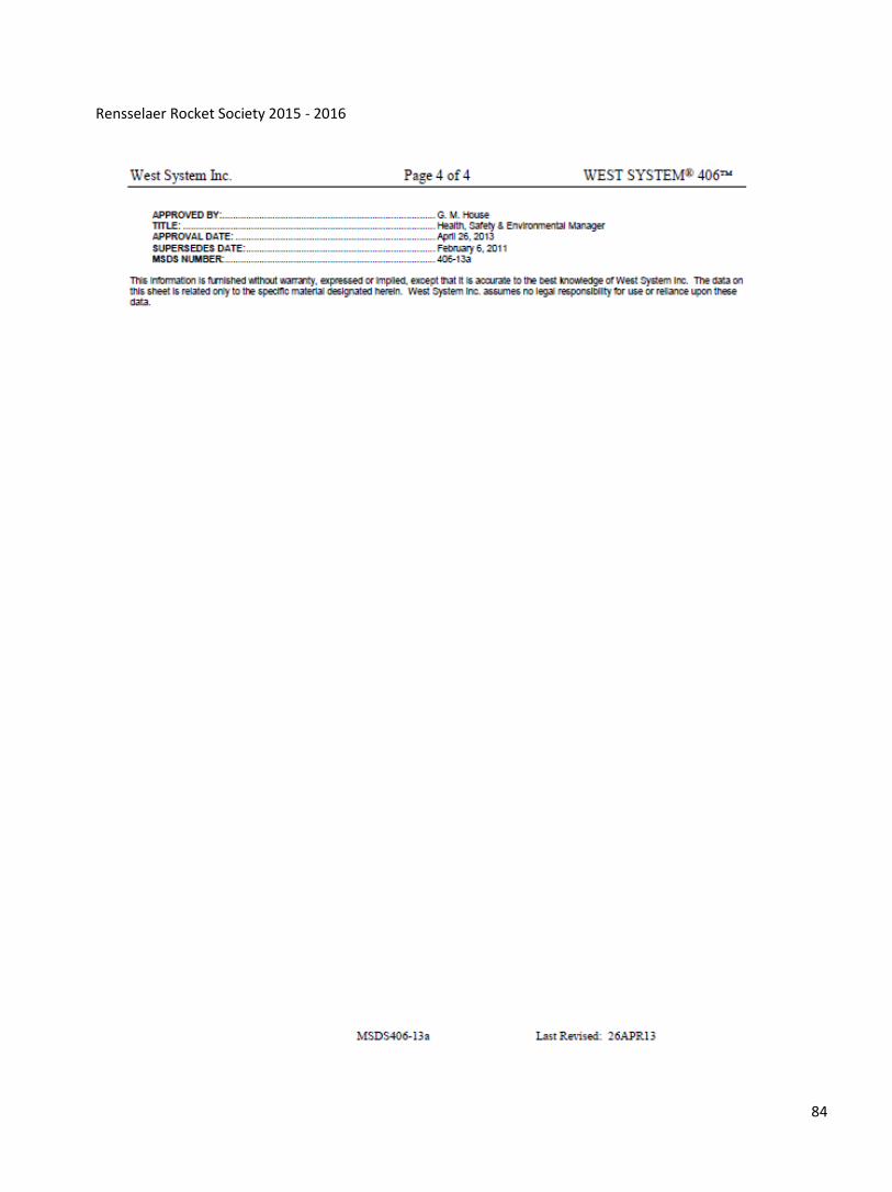
Appendix G: Material Safety Data Sheets
Content Page Number
(most commonly used materials listed; full list will be accessible in the RRS lab and on the RRS website)
J-B Weld and Kwik Twin-Tubes 32
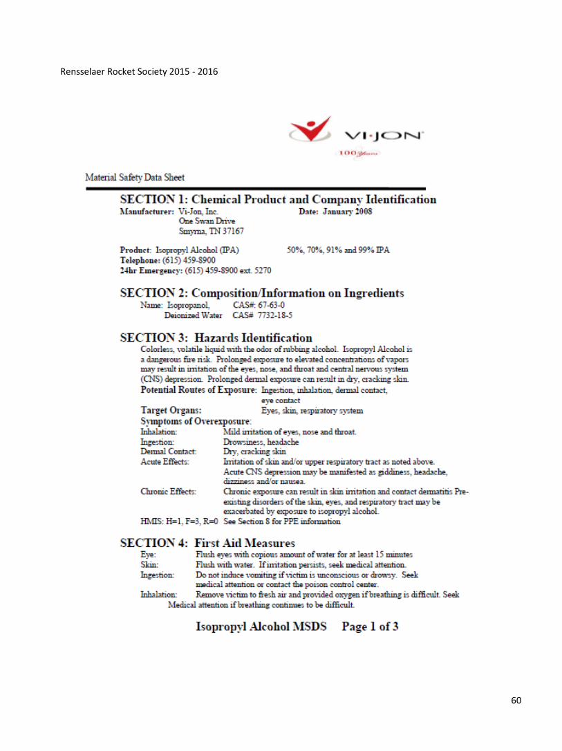
Vi Jon 91% Isopropyl Alcohol 54
West System 105 Epoxy Resin 57
West System 205 Fast Hardener 61
West System 206 Slow Hardener 65
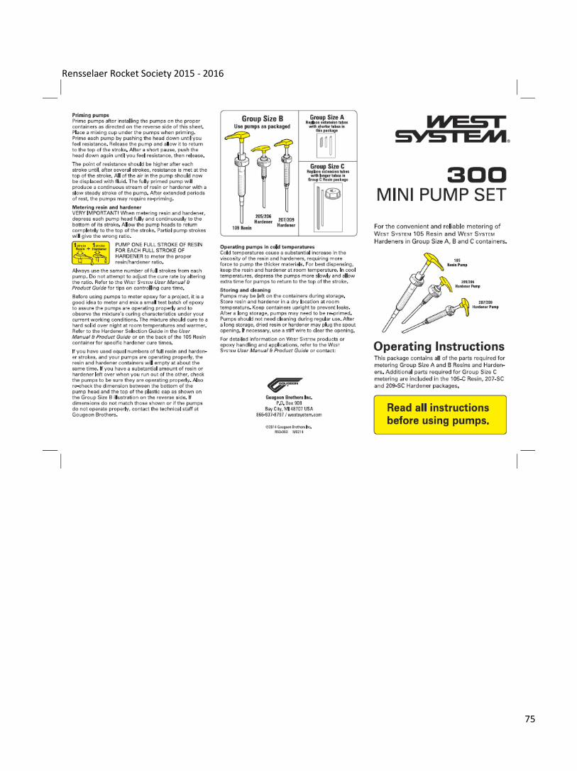
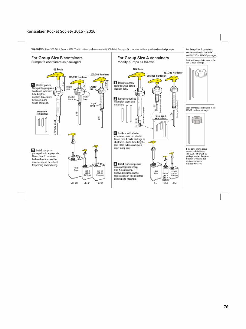
West System 300 Mini Pump Instructions 69
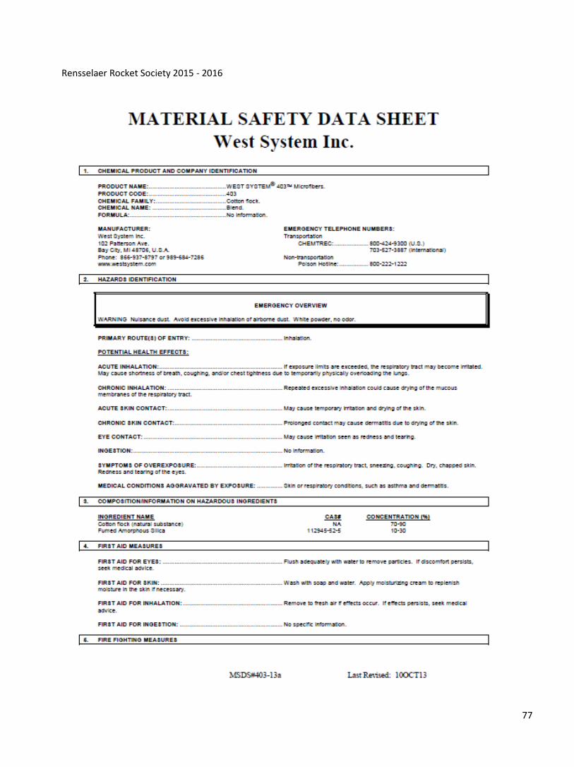
West System 403 Microfibers 71
West System 406 Colloidal Silica 75
Rensselaer Rocket Society 2015 - 2016
38
Rensselaer Rocket Society 2015 - 2016
39
Rensselaer Rocket Society 2015 - 2016
40
Rensselaer Rocket Society 2015 - 2016
41
Rensselaer Rocket Society 2015 - 2016
42
Rensselaer Rocket Society 2015 - 2016
43
Rensselaer Rocket Society 2015 - 2016
44
Rensselaer Rocket Society 2015 - 2016
45

Rensselaer Rocket Society 2015 - 2016
46
Rensselaer Rocket Society 2015 - 2016
47
Rensselaer Rocket Society 2015 - 2016
48
Rensselaer Rocket Society 2015 - 2016
49
Rensselaer Rocket Society 2015 - 2016
50
Rensselaer Rocket Society 2015 - 2016
51
Rensselaer Rocket Society 2015 - 2016
52
Rensselaer Rocket Society 2015 - 2016
53
Rensselaer Rocket Society 2015 - 2016
54
Rensselaer Rocket Society 2015 - 2016
55
Rensselaer Rocket Society 2015 - 2016
56
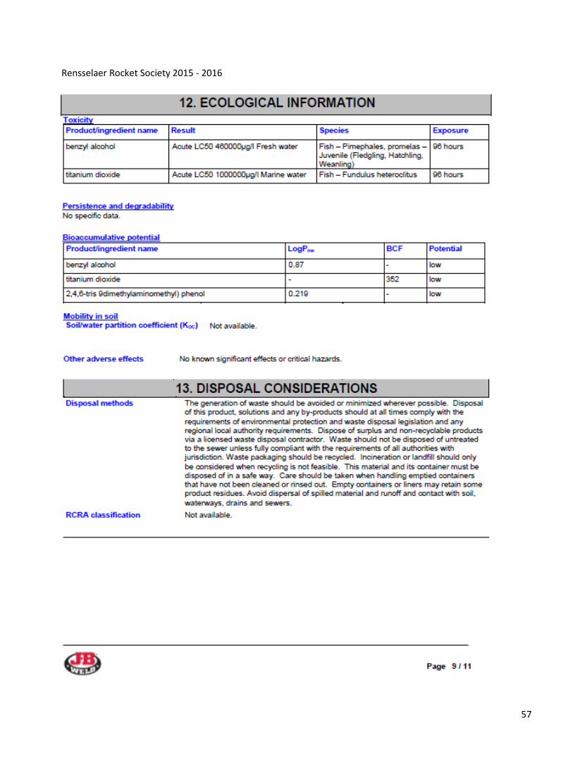
Rensselaer Rocket Society 2015 - 2016
57
Rensselaer Rocket Society 2015 - 2016
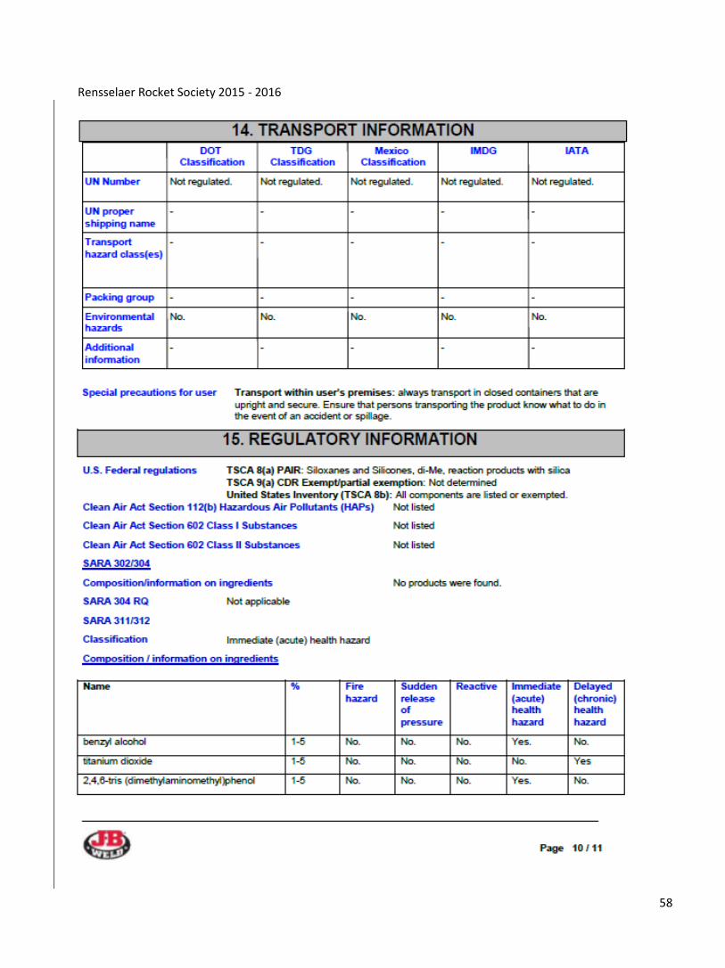
58
Rensselaer Rocket Society 2015 - 2016
59
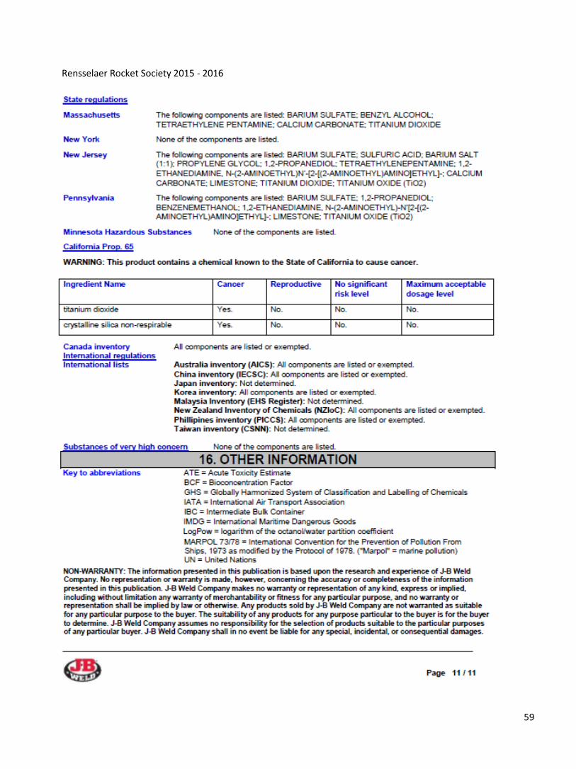
Rensselaer Rocket Society 2015 - 2016
60
Rensselaer Rocket Society 2015 - 2016
61
Rensselaer Rocket Society 2015 - 2016
62
Rensselaer Rocket Society 2015 - 2016
63

Rensselaer Rocket Society 2015 - 2016
64
Rensselaer Rocket Society 2015 - 2016
65
Rensselaer Rocket Society 2015 - 2016
66
Rensselaer Rocket Society 2015 - 2016
67
Rensselaer Rocket Society 2015 - 2016
68
Rensselaer Rocket Society 2015 - 2016
69
Rensselaer Rocket Society 2015 - 2016
70
Rensselaer Rocket Society 2015 - 2016
71
Rensselaer Rocket Society 2015 - 2016
72
Rensselaer Rocket Society 2015 - 2016
73
Rensselaer Rocket Society 2015 - 2016
74
Rensselaer Rocket Society 2015 - 2016
75
Rensselaer Rocket Society 2015 - 2016
76
Rensselaer Rocket Society 2015 - 2016
77
Rensselaer Rocket Society 2015 - 2016
78
Rensselaer Rocket Society 2015 - 2016
79
Rensselaer Rocket Society 2015 - 2016
80
Rensselaer Rocket Society 2015 - 2016
81
Rensselaer Rocket Society 2015 - 2016
82
Rensselaer Rocket Society 2015 - 2016
83
Rensselaer Rocket Society 2015 - 2016
84