2015-2016 ASCE Steel Bridge Project Proposal - na U ASCE Steel Bridge Project Proposal To ... 2.9.2...
16
2015-2016 ASCE Steel Bridge Project Proposal To CENE 476 Grading Instructor: Mark Lamer, P.E. From 2015-2016 ASCE Steel Bridge Team: Kaitlin Vandaveer Logan Couch Brian Jouflas Matthew Rodgers December 16 th , 2015
Transcript of 2015-2016 ASCE Steel Bridge Project Proposal - na U ASCE Steel Bridge Project Proposal To ... 2.9.2...
2015-2016 ASCE Steel Bridge Project Proposal
To
CENE 476 Grading Instructor:
Mark Lamer, P.E.
From
2015-2016 ASCE Steel Bridge Team:
Kaitlin Vandaveer
Logan Couch
Brian Jouflas
Matthew Rodgers
December 16th, 2015

Table of Contents
1.0 Project Understanding............................................................................................................ 1
1.1 Project Purpose ................................................................................................................... 1
1.2 Project Background ............................................................................................................ 1
1.3 Technical Considerations ................................................................................................... 1
1.4 Project Evaluation ............................................................................................................... 2
1.4.1 Member Constraints..................................................................................................... 2
1.4.2 Bridge Competition Constraints ................................................................................. 2
1.4.3 Bridge Competition Evaluation ................................................................................... 2
1.5 Potential Challenges ............................................................................................................ 3
1.6 Stakeholders ......................................................................................................................... 3
2.0 Scope of Services ..................................................................................................................... 3
2.1 Background Research ......................................................................................................... 4
2.1.1 Competition Rules ........................................................................................................ 4
2.1.2 Bridge Designs............................................................................................................... 4
2.1.3 Connections and Weld Types ...................................................................................... 4
2.1.4 Materials and Member Types ..................................................................................... 4
2.2 Preliminary Design .............................................................................................................. 4
2.2.1 Design Options .............................................................................................................. 4
2.2.2 Preliminary RISA 3D Models ...................................................................................... 4
2.2.3 Decision Matrix ............................................................................................................. 4
2.3 Final Design ......................................................................................................................... 4
2.3.1 RISA 3D ............................................................................................................................ 4
2.3.2 Member Design Details ................................................................................................ 5
2.3.3 Connection Design ........................................................................................................ 5
2.4 Bridge Design Plans ............................................................................................................ 5
2.4.1 30% Drawings ............................................................................................................... 5
2.4.2 60% Drawings ............................................................................................................... 5
2.4.3 90% Drawings ............................................................................................................... 5
2.5 Fabrication ........................................................................................................................... 5
2.5.1 Preparation.................................................................................................................... 5
2.5.2 Cutting ........................................................................................................................... 5
2.5.3 Drilling ........................................................................................................................... 5
2.5.4 Welding .......................................................................................................................... 6
2.6 Construction ........................................................................................................................ 6
2.6.1 Numbering ..................................................................................................................... 6
2.6.2 Construction Practice ................................................................................................... 6
2.7 Pacific Southwest Conference ............................................................................................ 6
2.7.1 Display Day ................................................................................................................... 6
2.7.2 Off-Center Load Case Location Determination ........................................................ 6
2.7.3 Timed Construction ...................................................................................................... 6
2.7.4 Loading and Weight ..................................................................................................... 6
2.8 Project Management ........................................................................................................... 7
2.8.1 Scheduling ..................................................................................................................... 7
2.8.2 Budget ............................................................................................................................ 7
2.8.3 Meetings ......................................................................................................................... 7
2.8.4 Fundraising and Donations.......................................................................................... 7
2.9 CENE 486 Deliverables ....................................................................................................... 7
2.9.1 50% Design Report ....................................................................................................... 7
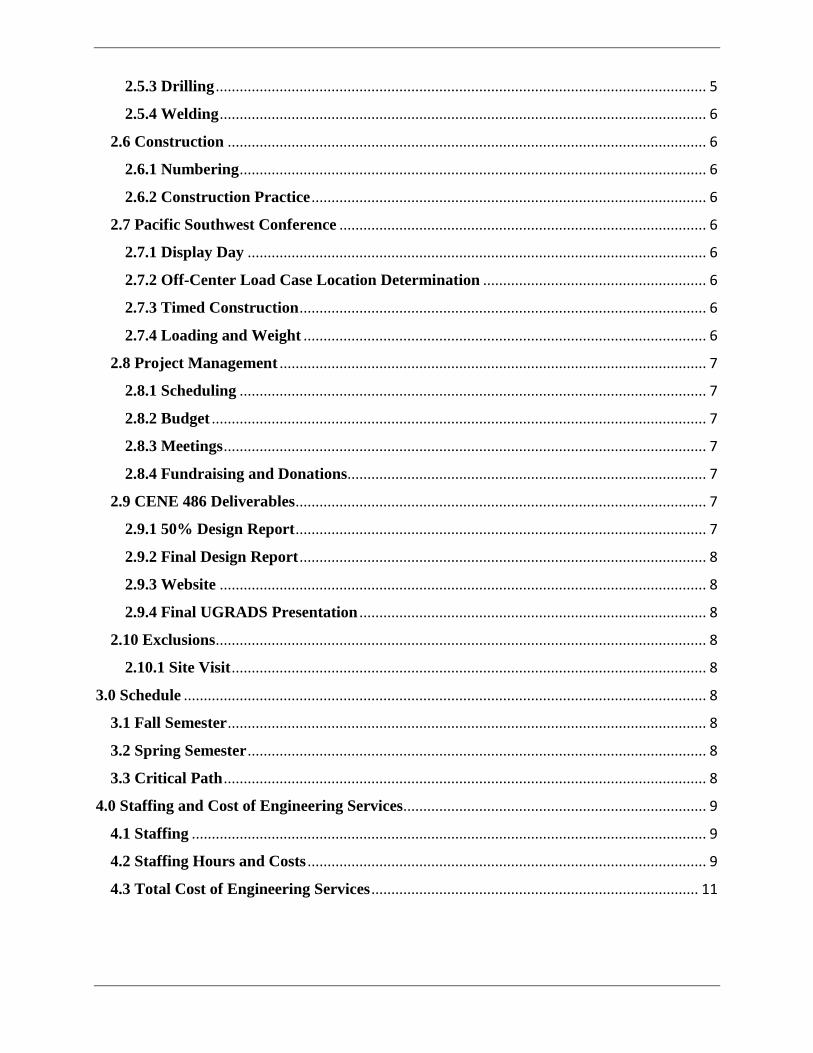
2.9.2 Final Design Report ...................................................................................................... 8
2.9.3 Website .......................................................................................................................... 8
2.9.4 Final UGRADS Presentation ....................................................................................... 8
2.10 Exclusions ........................................................................................................................... 8
2.10.1 Site Visit ....................................................................................................................... 8
3.0 Schedule ................................................................................................................................... 8
3.1 Fall Semester ........................................................................................................................ 8
3.2 Spring Semester ................................................................................................................... 8
3.3 Critical Path ......................................................................................................................... 8
4.0 Staffing and Cost of Engineering Services............................................................................ 9
4.1 Staffing ................................................................................................................................. 9
4.2 Staffing Hours and Costs .................................................................................................... 9
4.3 Total Cost of Engineering Services .................................................................................. 11
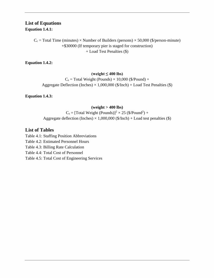
List of Equations
Equation 1.4.1:
Cc = Total Time (minutes) × Number of Builders (persons) × 50,000 ($/person-minute)
+$30000 (If temporary pier is staged for construction)
+ Load Test Penalties ($)
Equation 1.4.2:
(weight ≤ 400 lbs)
Cs = Total Weight (Pounds) × 10,000 ($/Pound) +
Aggregate Deflection (Inches) × 1,000,000 ($/Inch) + Load Test Penalties ($)
Equation 1.4.3:
(weight > 400 lbs)
Cs = [Total Weight (Pounds)]2 × 25 ($/Pound2) +
Aggregate deflection (Inches) × 1,000,000 ($/Inch) + Load test penalties ($)
List of Tables
Table 4.1: Staffing Position Abbreviations
Table 4.2: Estimated Personnel Hours
Table 4.3: Billing Rate Calculation
Table 4.4: Total Cost of Personnel
Table 4.5: Total Cost of Engineering Services
1
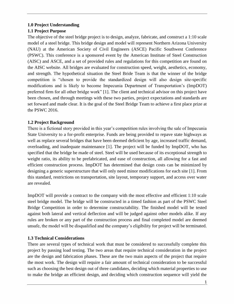
1.0 Project Understanding
1.1 Project Purpose
The objective of the steel bridge project is to design, analyze, fabricate, and construct a 1:10 scale
model of a steel bridge. This bridge design and model will represent Northern Arizona University
(NAU) at the American Society of Civil Engineers (ASCE) Pacific Southwest Conference
(PSWC). This conference is a sponsored event by the American Institute of Steel Construction
(AISC) and ASCE, and a set of provided rules and regulations for this competition are found on
the AISC website. All bridges are evaluated for construction speed, weight, aesthetics, economy,
and strength. The hypothetical situation the Steel Bride Team is that the winner of the bridge
competition is “chosen to provide the standardized design will also design site-specific
modifications and is likely to become Impecunia Department of Transportation’s (ImpDOT)
preferred firm for all other bridge work” [1]. The client and technical advisor on this project have
been chosen, and through meetings with these two parties, project expectations and standards are
set forward and made clear. It is the goal of the Steel Bridge Team to achieve a first place prize at
the PSWC 2016.
1.2 Project Background
There is a fictional story provided in this year’s competition rules involving the sale of Impecunia
State University to a for-profit enterprise. Funds are being provided to repave state highways as
well as replace several bridges that have been deemed deficient by age, increased traffic demand,
overloading, and inadequate maintenance [1]. The project will be funded by ImpDOT, who has
specified that the bridge be made of steel. Steel will be used because of its exceptional strength to
weight ratio, its ability to be prefabricated, and ease of construction, all allowing for a fast and
efficient construction process. ImpDOT has determined that design costs can be minimized by
designing a generic superstructure that will only need minor modifications for each site [1]. From
this standard, restrictions on transportation, site layout, temporary support, and access over water
are revealed.
ImpDOT will provide a contract to the company with the most effective and efficient 1:10 scale
steel bridge model. The bridge will be constructed in a timed fashion as part of the PSWC Steel
Bridge Competition in order to determine constructability. The finished model will be tested
against both lateral and vertical deflection and will be judged against other models alike. If any
rules are broken or any part of the construction process and final completed model are deemed
unsafe, the model will be disqualified and the company’s eligibility for project will be terminated.
1.3 Technical Considerations
There are several types of technical work that must be considered to successfully complete this
project by passing load testing. The two areas that require technical consideration in the project
are the design and fabrication phases. These are the two main aspects of the project that require
the most work. The design will require a fair amount of technical consideration to be successful
such as choosing the best design out of three candidates, deciding which material properties to use
to make the bridge an efficient design, and deciding which construction sequence will yield the

2
fastest construction time. Extensive design work is necessary to account for potential failures that
could occur throughout the bridge. A poor design can cause the fabrication and construction to
essentially be a waste of time.
The design portion is critical to the project, but fabrication also requires significant technical
consideration. Fabricating each steel member to match what the team designed requires a great
amount of expertise. This includes cutting, drilling, welding, and potentially rolling each member.
All of the fabricated members have to be similar so they can all be compatible and work together
to create a strong section. Previous competitions have had great designs that failed due to a fault
in the fabrication process.
1.4 Project Evaluation
1.4.1 Member Constraints
The 1:10 scale bridge will be designed within the parameters provided by ImpDot. The bridge can
only be constructed with members, loose bolts, and nuts made of steel. Each member is limited to
dimensions of three feet by six inches by four inches and each bolt must not exceed three inches
in length. The members of the bridge must retain its shape, dimensions, and rigidity during timed
construction and load testing.
1.4.2 Bridge Competition Constraints
Construction speed is the time it takes to construct the bridge model, with the addition of time
penalties accrued during construction. Time penalties are added to the overall construction time
each time equipment or a bridge member touch the river, the ground outside the staging area, or
the ground inside or outside the construction area. The time to construct the bridge must be less
than forty-five minutes, but anytime over thirty minutes will result in a total construction time of
180 minutes. Construction will be halted after 45 minutes regardless of build completion and
inspected for safety. If the bridge is deemed unsafe, the bridge will be disqualified from the
competition.
1.4.3 Bridge Competition Evaluation
Construction economy (Cc) determines the design cost and is calculated using Equation 1.4.1.
There is a maximum of six builders allowed for construction, and a temporary pier is allowed to
help span the river. Both factor into the construction costs and can vary depending on the team
needs. Penalties can be added to the construction economy for every instance a builder or a part of
their clothing touches the river or ground outside the construction area. The penalty will be
recorded as an additional builder. The structural efficiency (Cs) is used to judge the structural
design. Equation 1.4.2 or Equation 1.4.3 are used to calculate the structural efficiency, depending
on the overall weight of the bridge, the overall performance of the bridge will be judged on the
combination of the construction economy and the structural efficiency. The team with the lowest
score is deemed the winner of the competition.
3
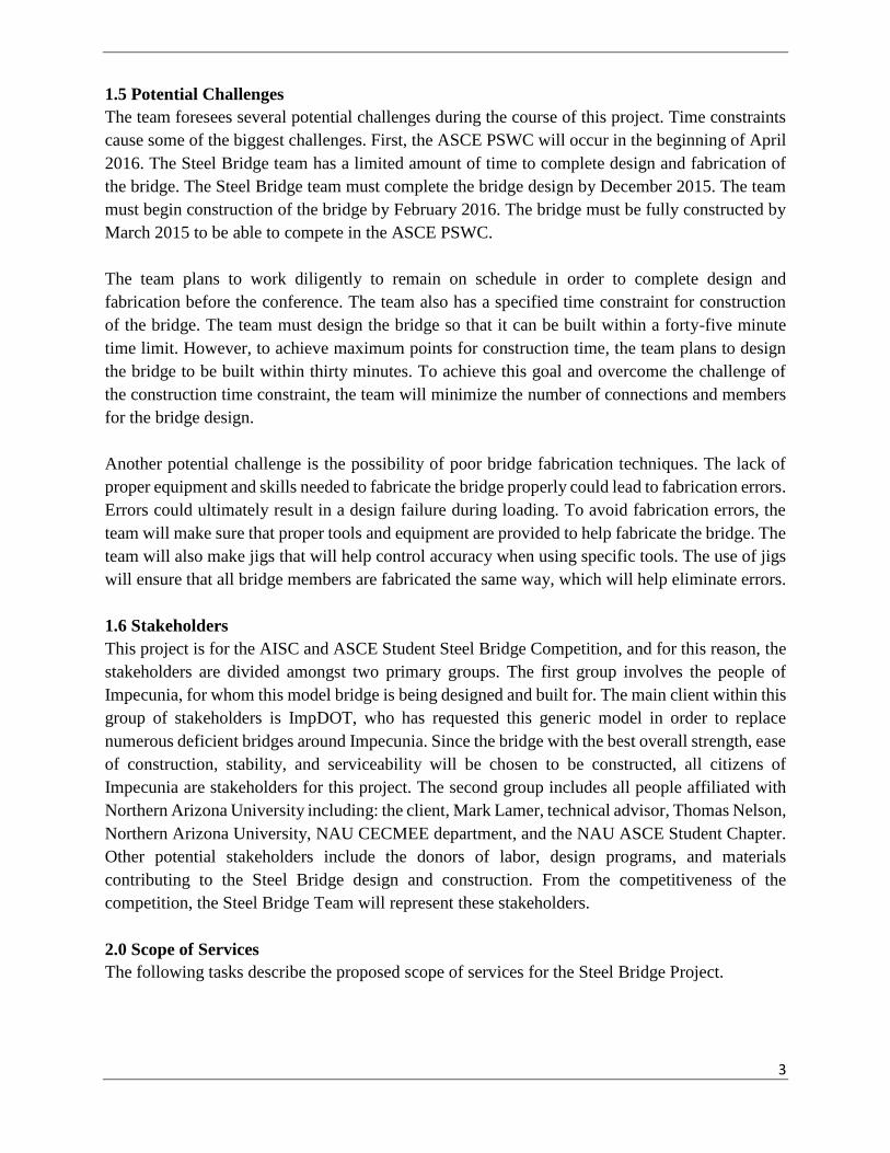
1.5 Potential Challenges
The team foresees several potential challenges during the course of this project. Time constraints
cause some of the biggest challenges. First, the ASCE PSWC will occur in the beginning of April
2016. The Steel Bridge team has a limited amount of time to complete design and fabrication of
the bridge. The Steel Bridge team must complete the bridge design by December 2015. The team
must begin construction of the bridge by February 2016. The bridge must be fully constructed by
March 2015 to be able to compete in the ASCE PSWC.
The team plans to work diligently to remain on schedule in order to complete design and
fabrication before the conference. The team also has a specified time constraint for construction
of the bridge. The team must design the bridge so that it can be built within a forty-five minute
time limit. However, to achieve maximum points for construction time, the team plans to design
the bridge to be built within thirty minutes. To achieve this goal and overcome the challenge of
the construction time constraint, the team will minimize the number of connections and members
for the bridge design.
Another potential challenge is the possibility of poor bridge fabrication techniques. The lack of
proper equipment and skills needed to fabricate the bridge properly could lead to fabrication errors.
Errors could ultimately result in a design failure during loading. To avoid fabrication errors, the
team will make sure that proper tools and equipment are provided to help fabricate the bridge. The
team will also make jigs that will help control accuracy when using specific tools. The use of jigs
will ensure that all bridge members are fabricated the same way, which will help eliminate errors.
1.6 Stakeholders
This project is for the AISC and ASCE Student Steel Bridge Competition, and for this reason, the
stakeholders are divided amongst two primary groups. The first group involves the people of
Impecunia, for whom this model bridge is being designed and built for. The main client within this
group of stakeholders is ImpDOT, who has requested this generic model in order to replace
numerous deficient bridges around Impecunia. Since the bridge with the best overall strength, ease
of construction, stability, and serviceability will be chosen to be constructed, all citizens of
Impecunia are stakeholders for this project. The second group includes all people affiliated with
Northern Arizona University including: the client, Mark Lamer, technical advisor, Thomas Nelson,
Northern Arizona University, NAU CECMEE department, and the NAU ASCE Student Chapter.
Other potential stakeholders include the donors of labor, design programs, and materials
contributing to the Steel Bridge design and construction. From the competitiveness of the
competition, the Steel Bridge Team will represent these stakeholders.
2.0 Scope of Services
The following tasks describe the proposed scope of services for the Steel Bridge Project.
4
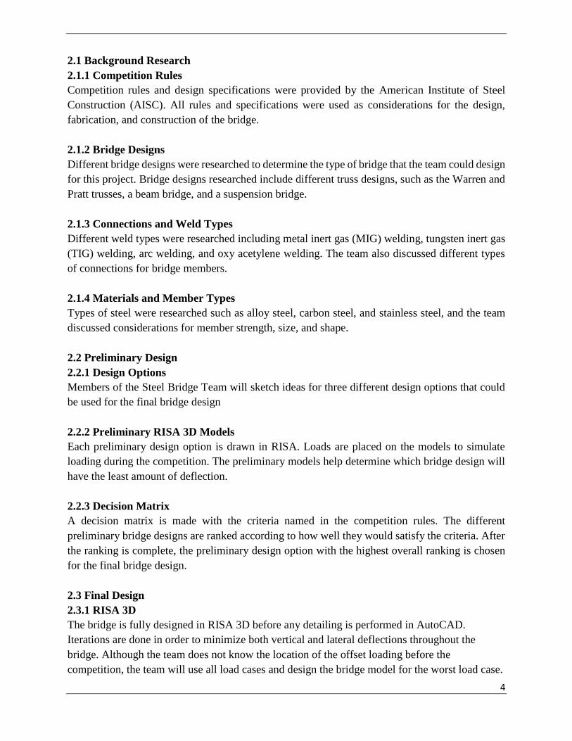
2.1 Background Research
2.1.1 Competition Rules
Competition rules and design specifications were provided by the American Institute of Steel
Construction (AISC). All rules and specifications were used as considerations for the design,
fabrication, and construction of the bridge.
2.1.2 Bridge Designs
Different bridge designs were researched to determine the type of bridge that the team could design
for this project. Bridge designs researched include different truss designs, such as the Warren and
Pratt trusses, a beam bridge, and a suspension bridge.
2.1.3 Connections and Weld Types
Different weld types were researched including metal inert gas (MIG) welding, tungsten inert gas
(TIG) welding, arc welding, and oxy acetylene welding. The team also discussed different types
of connections for bridge members.
2.1.4 Materials and Member Types
Types of steel were researched such as alloy steel, carbon steel, and stainless steel, and the team
discussed considerations for member strength, size, and shape.
2.2 Preliminary Design
2.2.1 Design Options
Members of the Steel Bridge Team will sketch ideas for three different design options that could
be used for the final bridge design
2.2.2 Preliminary RISA 3D Models
Each preliminary design option is drawn in RISA. Loads are placed on the models to simulate
loading during the competition. The preliminary models help determine which bridge design will
have the least amount of deflection.
2.2.3 Decision Matrix
A decision matrix is made with the criteria named in the competition rules. The different
preliminary bridge designs are ranked according to how well they would satisfy the criteria. After
the ranking is complete, the preliminary design option with the highest overall ranking is chosen
for the final bridge design.
2.3 Final Design
2.3.1 RISA 3D
The bridge is fully designed in RISA 3D before any detailing is performed in AutoCAD.
Iterations are done in order to minimize both vertical and lateral deflections throughout the
bridge. Although the team does not know the location of the offset loading before the
competition, the team will use all load cases and design the bridge model for the worst load case.

5
The RISA model is saved at multiple different times to save progress and go back to previous
iterations if necessary.
2.3.2 Member Design Details
The preliminary bridge design is refined from a preliminary stage to a final stage of design. All
member sizes and dimensions are determined, as well as the overall aesthetic of the bridge. A final
model is drawn in RISA 3D for an approximate estimate of member and joint deflection.
2.3.3 Connection Design
The joint connections are designed based on the overall configuration of the bridge design. Plates
are designed for each member and bolt capacity is determined. From the bolt capacity, a bolt size
is chosen for each connection.
2.4 Bridge Design Plans
2.4.1 30% Drawings
The 30% drawings will include general plan and elevation views of the bridge showing
preliminary dimensions
2.4.2 60% Drawings
The 60% drawings will include detailed plan and elevation views of the bridge showing final
dimensions
2.4.3 90% Drawings
The 90% drawings will be comprised of all bridge details including detailed plan and elevation
views, connection design details, and member cross sections. All drawings will show final
dimensions.
2.5 Fabrication
2.5.1 Preparation
At the start of the fabrication phase, the team will perform numerous tasks to make fabrication
go as easy and fast as possible. Some of these tasks include fully cleaning all steel acquired
through donations and making several jigs so every piece will be of equal size for multiple
different member lengths.
2.5.2 Cutting
All bridge members and plates are measured to the appropriate size according to the dimensions
specified in the design plans, and then cut based on the measurements.
2.5.3 Drilling
After plates are cut to the correct dimensions, locations of all bolt holes are measured out per the
design plans, and are then drilled to the correct bolt size using a drill press.

6
2.5.4 Welding
Bridge members and plates are welded together according to the design plans.
2.6 Construction
2.6.1 Numbering
A numbering system is created for all bridge members to help with ease of construction.
2.6.2 Construction Practice
Team members will practice constructing the bridge to determine an efficient way to build it during
the competition as well as to reduce the construction time.
2.7 Pacific Southwest Conference
2.7.1 Display Day
The first day of the Pacific Southwest Conference is the display day for each team’s steel bridge
design. A display board is made showing the name of the university, why the bridge design is
chosen, a scaled side view of the bridge, a free-body diagram for one of the six load cases, shear
and moment diagrams for the chosen free-body diagram, provisions for Accelerated Bridge
Construction (ABC), and acknowledgement of all sponsors and donors who helped in any way
throughout the entire bridge design build process. An award is given for display and is judged on
the following criteria: appearance including balance, proportion, elegance and finish, and
permanent identification of the bridge showing the university name exactly as shown on the ASCE
student web page.
2.7.2 Off-Center Load Case Location Determination
Before conference, every team is given six different load cases to design for. The night before
the construction day, all conference captains meet with the head judge to ask any final questions.
Also at this meeting, a die will be rolled to determine the location of the off-center load.
2.7.3 Timed Construction
The day of the competition, all teams are to build their designed bridge in a timed fashion.
Before starting, all bridge members, fasteners, temporary pier (if used), and tools are staged and
inspected by the judges. Every team is given a thirty-minute time limit to build the bridge
without any penalties and a maximum time limit of forty-five minutes to build the bridge without
being disqualified from the competition.
2.7.4 Loading and Weight
After timed construction is completed, each team moves their bridge to the loading area. The judge
decides an “A” side of the bridge by a random process and the other side is determined as the “B”
side. The decking units are then placed; one is placed at 8’-9” from the right side and the other is
placed at the location of the load case chosen the night before construction, specified as distance
“D”. Three vertical deflection gauges are placed, one on the “A” side at a distance D + 3’-0” from
the right end of the decking unit, and two on the “B” side, one at a distance D + 1’-6” from the

7
right end of the decking unit and the other at a distance 10’-3” from the right end of the decking
unit.
Lateral loading is tested first and seventy-five pounds is placed on the “B” side of the bridge to
help restrain the bearing surfaces of the bridge from uplifting. Then, fifty pounds of lateral load is
placed as close to the decking unit as possible. One inch of sway is allowed for the bridge to pass
lateral loading. The next loading condition is the vertical loading test. Fifty pounds of pre-load is
evenly distributed across the decking units. From there, 1000 pounds of additional load is placed
on the off-center decking units and 1400 pounds of additional load is placed on the center-decking
unit. All loads are placed in a manner of individual twenty-five pound pieces of angle iron. Three
inches of aggregate deflection is allowed for the bridge to pass vertical loading. Last, if the bridge
passes both lateral and vertical loading, the bridge is moved to be weighed on four scales, one for
each foot of the bridge, and the totals are summed to gain a final weight.
2.8 Project Management
2.8.1 Scheduling
A schedule is created to stay on track during the course of the project. Each major task is listed on
the schedule with approximate start and finish dates, along with subtasks that are included as a part
of the critical path.
2.8.2 Budget
A budget is created based on the amount of time needed to complete the project, as well as the
resources required. This includes the personnel and materials that are necessary for the completion
of the project. The budget also takes into account any donations that are received to help fund the
project.
2.8.3 Meetings
The team will have weekly meetings to discuss the progress of the bridge. The team will also meet
with the Technical Advisor and Client as necessary.
2.8.4 Fundraising and Donations
The team will contact different resources in the hopes of acquiring donated materials or funds. For
any donated materials, the team will be in contact with vendors throughout the course of the design
phase of the project. This helps ensure that all materials that will be used for final bridge design
are readily available when the fabrication phase begins.
2.9 CENE 486 Deliverables
2.9.1 50% Design Report
The Steel Bridge Team will prepare and submit a 50% design report summarizing the
preliminary design of the bridge. The report serves as a rough draft for the final design report.
8
2.9.2 Final Design Report
The final design report will provide an overview of the scope of work completed for the project.
This work includes the design, fabrication, and plans used in the project.
2.9.3 Website
A website will be created to show all aspects of the project, including the final chosen design,
AutoCAD shop drawings, and results from the ASCE Pacific Southwest Conference.
2.9.4 Final UGRADS Presentation
The team will present the all details for final project along with the results from the ASCE
Pacific Southwest Conference.
2.10 Exclusions
2.10.1 Site Visit
The Steel Bridge Team will not be visiting the construction site prior to the day of construction
and loading.
3.0 Schedule
3.1 Fall Semester
In the fall semester, the team will focus primarily on completing the steel bridge design. This is
shown in the Gantt chart by the research, decisions, and designs scheduled. The fundamentals to
the bridge design will be researched to give the team a better understanding of what needs to be
completed. The three different preliminary designs will be modeled and evaluated to determine
the best option for a final bridge design. Once a final design is chosen, the connections and member
details will be designed. Ninety percent of the design will be completed by Thanksgiving to ensure
the team has enough time to pick up materials from sponsors.
3.2 Spring Semester
In the spring semester, the team will primarily be fabricating and building the bridge. After the
team receives the steel, fabrication of the bridge can begin. The team plans to work on the bridge
as soon as the semester begins. Cutting, drilling, and welding take most of the time to complete
and are the bulk of the fabrication work. The team will allot forty days to complete the three tasks
because of the large amount of work required. After all of the pieces are fabricated, the team will
schedule a day to number the pieces to make construction of the bridge easier. The team will then
begin construction practice to achieve a build time under thirty minutes. The team will also submit
class deliverables on their respective due dates.
3.3 Critical Path
The critical path for this project consists of two major tasks. The critical path includes both the
design and the fabrication of the bridge. These two tasks are the main components of the bridge
and will take the longest to complete. The team estimates the design will take 40 days to complete
with another 20 days for finalization of the design and AutoCAD shop drawings, and the

9
fabrication will take 40 days to complete. This totals to approximately 100 days to complete the
critical path of the project.
The Gantt Chart showing the full project schedule and critical path (shown in red) can be seen in
Appendix A.
4.0 Staffing and Cost of Engineering Services
Staffing costs and costs of engineering services are determined based on the scope of services that
are necessary for completing this project.
4.1 Staffing
The team that will complete the Steel Bridge Project is comprised of eight team members total:
four engineers and four interns. The team of engineers consists of a project manager, a conference
captain, a RISA 3D design engineer, and an AutoCAD design manager. The project manager is in
charge of oversight for the project, making sure deadlines are met and that the team stays on task.
The conference captain coordinates all scope items related the ASCE PSWC, which includes
acting as safety manager and captain during construction and loading at the competition. The
design engineer manages the overall design of the bridge and the RISA model created for the
design. The AutoCAD manager is in charge of the full set of AutoCAD plans for the bridge after
the design is complete. The four interns on the project will be assigned small tasks for various
scope items, consisting mostly of assistance with fabrication and construction. Table 4.1 shows
job classifications for the steel bridge project with abbreviations for each position that will be used
for reference for all staffing hours and costs.
Table 4.1: Staffing Position Abbreviations
Title Abbreviation
Project Manager PM
Conference Captain CNFCPT
RISA 3D Design Engineer DSNENG
AutoCAD Design Manager CADMGR
Intern (Four) INT (4)
4.2 Staffing Hours and Costs
Based on the scope tasks for the project, the team compiled a table of estimated hours for all
personnel. The hours are projected for the total approximate hours each team member will spend
on each task item. Table 4.2 shows the estimated personnel hours for the duration of the project.
The major tasks are listed in bold print and the subtasks for are listed below each major task. The
hours in bold for each major task are the total amount of hours that will be spend on that item, and
the hours for each subtask sum to the total hours for each major task. The team projects a total of
1080 hours for the Steel Bridge Project.

10
Table 4.2 Estimated Personnel Hours
Task PM CNFCPT DSNENG CADMGR INT (4)
1.0 Background Research 0 5 5 5 5
2.0 Preliminary Design 0 5 20 10 20
3.0 Final Design 20 40 80 80 60
3.1 RISA 3D 10 20 60 10 20
3.2 Member Design Details 5 10 10 35 20
3.3 Connection Design 5 10 10 35 20
4.0 Bridge Design Plans 5 10 40 60 40
4.1 30% Shop Drawings 1 5 20 30 20
4.2 60% Shop Drawings 2 3 10 20 10
4.3 90% Shop Drawings 2 2 10 10 10
5.0 Fabrication 20 60 40 40 60
5.1 Preparation 5 15 10 10 15
5.2 Cutting 5 15 10 10 15
5.3 Drilling 5 15 10 10 15
5.4 Welding 5 15 10 10 15
6.0 Construction 15 40 25 25 40
6.1 Numbering 5 5 5 5 5
6.2 Construction Practice 10 35 20 20 35
7.0 Pacific Southwest Conference 15 40 15 15 20
8.0 Project Management 15 10 10 10 5
9.0 CENE 486 Deliverables 5 15 15 15 0
9.1 50% Design Report 1 5 5 5 0
9.2 Final Design Report 2 5 5 5 0
9.3 Website 1 3 3 3 0
9.4 UGRADS Presentation 1 2 2 2 0
Total Hours/Personnel 95 225 250 260 250
Total Hours 1080
Billing rates per hour for each project team member are determined based on percentages of
benefits, overhead, and profit. Table 4.3 shows the billing rates per hour for each member of the
staffing team based on the applied multipliers.
Table 4.3: Billing Rate Calculation
Personnel Task Name Billing
Rate
[$/hr.]
Base
Pay
Benefit
[%]
Actual
Pay
Overhead
[%]
Profit
[%]
PM 60 20 72 30 10 105
CNFCPT 55 15 63.25 30 10 90
DSNENG 50 15 57.5 30 10 85
CADMGR 35 15 40.25 30 10 60
INT (4) 10 0 10 30 10 15
11
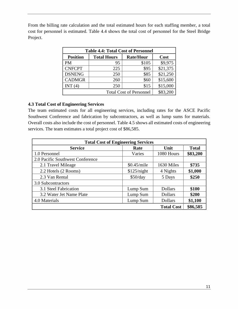
From the billing rate calculation and the total estimated hours for each staffing member, a total
cost for personnel is estimated. Table 4.4 shows the total cost of personnel for the Steel Bridge
Project.
Table 4.4: Total Cost of Personnel
Position Total Hours Rate/Hour Cost
PM 95 $105 $9,975
CNFCPT 225 $95 $21,375
DSNENG 250 $85 $21,250
CADMGR 260 $60 $15,600
INT (4) 250 $15 $15,000
Total Cost of Personnel $83,200
4.3 Total Cost of Engineering Services
The team estimated costs for all engineering services, including rates for the ASCE Pacific
Southwest Conference and fabrication by subcontractors, as well as lump sums for materials.
Overall costs also include the cost of personnel. Table 4.5 shows all estimated costs of engineering
services. The team estimates a total project cost of $86,585.
Total Cost of Engineering Services
Service Rate Unit Total
1.0 Personnel Varies 1080 Hours $83,200
2.0 Pacific Southwest Conference
2.1 Travel Mileage $0.45/mile 1630 Miles $735
2.2 Hotels (2 Rooms) $125/night 4 Nights $1,000
2.3 Van Rental $50/day 5 Days $250
3.0 Subcontractors
3.1 Steel Fabrication Lump Sum Dollars $100
3.2 Water Jet Name Plate Lump Sum Dollars $200
4.0 Materials Lump Sum Dollars $1,100
Total Cost $86,585

12
5.0 References
[1] Aisc.org, 'Student Steel Bridge Competition Rules', 2015. [Online]. Available:
https://www.aisc.org/WorkArea/showcontent.aspx?id=21576. [Accessed: 30- Sep- 2015]