2014oct-3 Tanaka3 Kakamigahara Bridge - JSCE · Kakamigahara Bridge (Figure 1) is a 10-span...
4
Kakamigahara Bridge - 1 - Kakamigahara Bridge Kakamigahara Bridge (Figure 1) is a 10-span continuous fin-back prestressed concrete bridge that crosses the Kiso river. It is part of the Nakakoami line that connects Jogo-cho and Kawashimakoami-machi in Kakamigahara city. The cross section of the main girder is a conventional double cell girder with a fin-back structure and multiple curved surfaces. To quickly begin traffic services, the bridge was constructed using the cantilever method and a launching girder system that was operable even during the flooding season. Structural Data Structure: 10-span continuous fin-back bridge Bridge Length: 594.0 m Span: 54.9 m+8 @ 60.0 m+55.9 m Width: driveway 7.5 - 10.5 m sidewalk 3.0 - 5.0 m Owner: Kakamigahara City Location: Kakamigahara City, Gifu Prefecture 1. Introduction Kakamigahara City merged with Kawashima Town on November 1 st , 2004. The new Kakamigahara City decided to build the Nakakoami Line, including the Kakamigahara Bridge, to relieve traffic congestion and expand exchanges between the two regions. To evaluate bridge designs, the city formed a planning committee that included third party experts. Based on themes suggested by the committee—a simple and modest appearance that’s harmonious with the great landscape around Kiso River, and a friendly bridge from which people can enjoy the natural scenery and the Kiso River—a 594-meter long 10-span continuous fin-back Figure 1. Kakamigahara Bridge Figure 2. Over view
Transcript of 2014oct-3 Tanaka3 Kakamigahara Bridge - JSCE · Kakamigahara Bridge (Figure 1) is a 10-span...
Kakamigahara Bridge
- 1 -
Kakamigahara Bridge Kakamigahara Bridge (Figure 1) is a 10-span continuous fin-back prestressed concrete bridge
that crosses the Kiso river. It is part of the Nakakoami line that connects Jogo-cho and Kawashimakoami-machi in Kakamigahara city. The cross section of the main girder is a conventional double cell girder with a fin-back structure
and multiple curved surfaces. To quickly begin traffic services, the bridge was constructed using the cantilever method and a
launching girder system that was operable even during the flooding season.
Structural Data
Structure: 10-span continuous fin-back bridge Bridge Length: 594.0 m Span: 54.9 m+8 @ 60.0 m+55.9 m Width: driveway 7.5 - 10.5 m sidewalk 3.0 - 5.0 m Owner: Kakamigahara City Location: Kakamigahara City, Gifu Prefecture
1. Introduction Kakamigahara City merged with Kawashima Town on November 1st, 2004. The new
Kakamigahara City decided to build the Nakakoami Line, including the Kakamigahara Bridge, to relieve traffic congestion and expand exchanges between the two regions. To evaluate bridge designs, the city formed a planning committee that included third party experts. Based on themes suggested by the committee—a simple and modest appearance that’s harmonious with the great landscape around Kiso River, and a friendly bridge from which people can enjoy the natural scenery and the Kiso River—a 594-meter long 10-span continuous fin-back
Figure 1. Kakamigahara Bridge
Figure 2. Over view

Kakamigahara Bridge
- 2 -
bridge design was adopted. A general view is shown in Figure 3. A cross-section of the main girder is shown in Figure 4.
Figure 3. General view
Figure 4. Cross-section of main girder
2. Features of this bridge (1) Unique fin-back main girder section This bridge has gentle curves and blends in with the surrounding mountains. The section is a
double-cell fin-back girder with multiple curved surfaces. The roadway is cast-in-place concrete, and the sidewalk is precast RC brackets and PC panels. (2) Short construction period To shorten the construction period, the bridge was constructed using the cantilever erection
method and a launching girder that was could be operated even during the flooding season. This method uses a formwork system that hangs from the launching girder. Equipment and workers move through previously constructed bridges and the launching girder, eliminating the need for a temporary jetty.
Kakamigahara Bridge
- 3 -
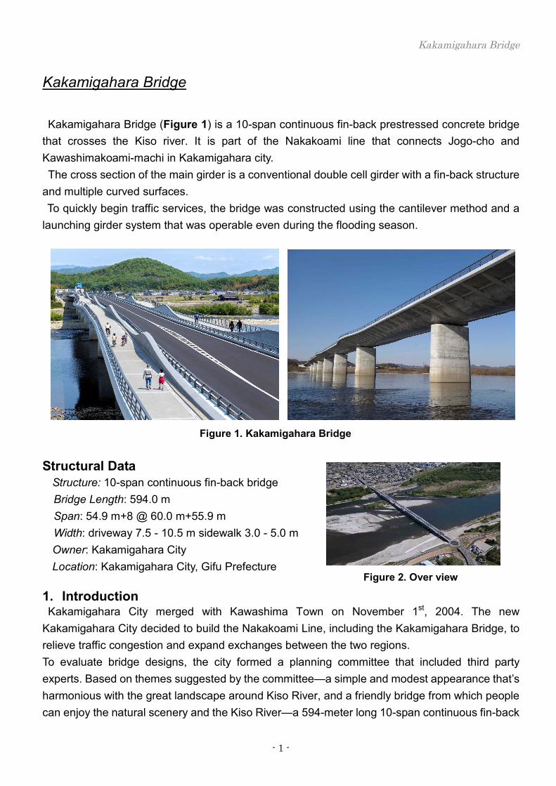
Launching GirderFormwork system for balanced cantilever
Support(R3)Support(R1) Support(R2)
Figure 5. P&Z cantilever erection system (small system)
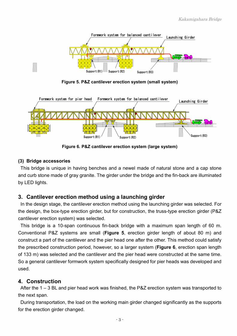
Launching GirderFormwork system for balanced cantileverFormwork system for pier head
Support(R3)Support(R2)Support(R1)
Figure 6. P&Z cantilever erection system (large system)
(3) Bridge accessories This bridge is unique in having benches and a newel made of natural stone and a cap stone
and curb stone made of gray granite. The girder under the bridge and the fin-back are illuminated by LED lights. 3. Cantilever erection method using a launching girder In the design stage, the cantilever erection method using the launching girder was selected. For
the design, the box-type erection girder, but for construction, the truss-type erection girder (P&Z cantilever erection system) was selected. This bridge is a 10-span continuous fin-back bridge with a maximum span length of 60 m.
Conventional P&Z systems are small (Figure 5, erection girder length of about 80 m) and construct a part of the cantilever and the pier head one after the other. This method could satisfy the prescribed construction period, however, so a larger system (Figure 6, erection span length of 133 m) was selected and the cantilever and the pier head were constructed at the same time. So a general cantilever formwork system specifically designed for pier heads was developed and used. 4. Construction After the 1 – 3 BL and pier head work was finished, the P&Z erection system was transported to
the next span. During transportation, the load on the working main girder changed significantly as the supports
for the erection girder changed.
Kakamigahara Bridge
- 4 -
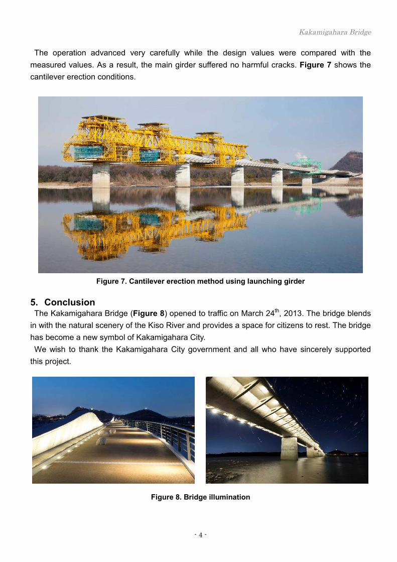
The operation advanced very carefully while the design values were compared with the measured values. As a result, the main girder suffered no harmful cracks. Figure 7 shows the cantilever erection conditions.
Figure 7. Cantilever erection method using launching girder
5. Conclusion The Kakamigahara Bridge (Figure 8) opened to traffic on March 24th, 2013. The bridge blends
in with the natural scenery of the Kiso River and provides a space for citizens to rest. The bridge has become a new symbol of Kakamigahara City. We wish to thank the Kakamigahara City government and all who have sincerely supported
this project.
Figure 8. Bridge illumination