
2014 Speed Concept: Service Informationtrek.scene7.com/is/content/TrekBicycleProducts/... · When...
57
When we introduced the Trek Speed Concept bike in 2011, it was the fastest frameset we had ever made. The 2014 version is even faster. It has shaped tubes, hidden front and rear brakes, very thin-walled carbon tubes, and a new front-end design including a new handlebar configuration. Special Assembly Techniques Required Because of the unique features of the Speed Concept, it requires assembly and adjustment techniques that are different from other bikes that are explained in this manual. We have also provided general maintenance information: • Carbon fiber care • Head bearings installation • Bottom bracket bearing installation for a variety of bottom bracket types Please save these instructions for future reference. Also check www.trekbikes.com for updates. Some of the tasks in these instructions may have been done by the factory. We include the instructions for these steps here for later reference when you need to perform service on this bike. Note: Instrucons for the Shimano electronic Di2 shiſt system are in a separate document. See your dealer. These instructions are written for an experienced mechanic. If you need further information, refer to your bicycle owner’s manual, the instructions in a bicycle mechanic’s handbook, or consult your dealer. These instructions are not intended to replace the information in the Trek Bicycle Owner’s Manual. You should also read that manual as it contains important use, safety, and maintenance information that also pertains to the assembly of this bicycle. Note About Performing Mechanical Work On Bicycles Many people think of bicycles as simple machines, almost toys. However, modern bicycles use high-tech materials and designs that rely on correct maintenance and precision workmanship. If any part on the bicycle is worn, corroded, rusted, loose, or damaged in any other way, replace the part. If you do not have the correct tools or experience, do not perform the tasks in this manual; take your bicycle to your dealer for service. In some cases we provide several methods of checking the tightness or connection of parts. The most preferable of these is always the one with the most precision. In other words, correct mechanical work requires that all bolts be tightened with a torque wrench. Incorrect mechanical work on your bicycle could lead to damage or premature breakage of a part, which could cause you to fall and lead to serious injury or death. 2014 Speed Concept: Service Informaon © Copyright Trek Bicycle Corporaon 2016 All Rights Reserved
Transcript of 2014 Speed Concept: Service Informationtrek.scene7.com/is/content/TrekBicycleProducts/... · When...
When we introduced the Trek Speed Concept bike in 2011, it was the fastest frameset we had ever made. The 2014 version is even faster. It has shaped tubes, hidden front and rear brakes, very thin-walled carbon tubes, and a new front-end design including a new handlebar configuration.
Special Assembly Techniques RequiredBecause of the unique features of the Speed Concept, it requires assembly and adjustment techniques that are different from other bikes that are explained in this manual. We have also provided general maintenance information:
• Carbon fiber care
• Head bearings installation
• Bottom bracket bearing installation for a variety of bottom bracket types
Please save these instructions for future reference. Also check www.trekbikes.com for updates.
Some of the tasks in these instructions may have been done by the factory. We include the instructions for these steps here for later reference when you need to perform service on this bike.Note: Instructions for the Shimano electronic Di2 shift system are in a separate document. See your dealer.
These instructions are written for an experienced mechanic. If you need further information, refer to your bicycle owner’s manual, the instructions in a bicycle mechanic’s handbook, or consult your dealer. These instructions are not intended to replace the information in the Trek Bicycle Owner’s Manual. You should also read that manual as it contains important use, safety, and maintenance information that also pertains to the assembly of this bicycle.
Note About Performing Mechanical Work On BicyclesMany people think of bicycles as simple machines, almost toys. However, modern bicycles use high-tech materials and designs that rely on correct maintenance and precision workmanship. If any part on the bicycle is worn, corroded, rusted, loose, or damaged in any other way, replace the part. If you do not have the correct tools or experience, do not perform the tasks in this manual; take your bicycle to your dealer for service.
In some cases we provide several methods of checking the tightness or connection of parts. The most preferable of these is always the one with the most precision. In other words, correct mechanical work requires that all bolts be tightened with a torque wrench.
Incorrect mechanical work on your bicycle could lead to damage or premature breakage of a part, which could cause you to fall and lead to serious injury or death.
2014 Speed Concept: Service Information
© Copyright Trek Bicycle Corporation 2016
All Rights Reserved
ii TREK SERVICE INFORMATION August 2016
Table of Contents
1. Working with Carbon Fiber Parts ............................................................ 1
2. Speed Concept General Information .................................................... 2
Changes From The Previous Version .....................................................2
Special Features And Assembly Information ......................................2
Preparing And Tightening Fasteners ......................................................3
For More Information ................................................................................3
3. Sizing The Bike .............................................................................................3
4. Seatpost ...................................................................................................... 4
To Install The Seatpost ..............................................................................5
To Adjust The Height Of The Saddle .....................................................5
To Adjust The Angle (Tilt) Of The Saddle ............................................5
5. Using A Repair Stand ................................................................................ 6
To Attach The Workstand Clamp Adapter ..........................................6
6. Fork ................................................................................................................ 7
To Install The Bearings And Fork ............................................................8
To Remove The Fork ...................................................................................9
7. Cables, Housings, And Bar Assembly ...................................................11
To Install The Housings In The Frame ................................................. 12
To Install Housings In The Mono-Extension And Aerobar ............ 14
8. Arm supports .............................................................................................19
To Install arm supports ........................................................................... 20
9. Derailleurs ................................................................................................. 22
To Install The Front Derailleur ..............................................................23
10. Front Brake ...............................................................................................24
To Install And Adjust The Front Brake .................................................25
11. Rear Brake .................................................................................................28
To Install And Adjust The Rear Brake ................................................. 29
12. DuoTrap Computer Sensor .................................................................. 32
To Install A DuoTrap Sensor ...................................................................32
13. Accessories .............................................................................................. 33
To Install A Draft Storage Box................................................................33
To Install A Speed Box ............................................................................ 34
To Install A Bottle Cage ...........................................................................35
14. Crankset ................................................................................................... 37
To Install The Axle Shields ......................................................................37
Pressing Crankset Bearings ................................................................... 38
SRAM GXP ................................................................................................ 39
Shimano HollowTech .............................................................................. 43
Campagnolo UltraTorque ...................................................................... 47
FSA MegaExo AL ...................................................................................... 51
Crankset Troubleshooting...................................................................... 54
1 TREK SERVICE INFORMATION August 2016
1. Working with Carbon Fiber PartsCarbon fiber parts are different from metal parts, so they require different treatment. This section explains some of the specifics. Also see the Trek Bicycle Owner’s Manual.
Avoid Sharp Edges Or Excessive PressureCarbon fiber composite can be damaged by sharp edges or clamping mechanisms which cause a point load, or a high pressure area. Before installing any carbon fiber part, or attaching any component to an existing carbon fiber part, follow these procedures to make sure the parts or components are carbon-compatible.
As carbon frames have gotten lighter and lighter, you can now feel movement in the tubes when you squeeze them. This is normal and no reflection of the strength of the frame. However, repeated compression of the sides of the tubes is not good for them, and could eventually lead to frame damage. Do not squeeze the frame tubing with your fingers, and especially never clamp the tubing in any mechanical device, including car racks.
Prepare Carbon Parts Before InstallationCarbon parts can be assembled either clean or with carbon prep:
• To clean a carbon part, scrub both the part and its mating surface with rubbing alcohol and a shop rag; clean until the rag shows no discoloration.
• Alternately, we recommend applying one of the following special carbon prep products:
• Fiber Grip™ carbon fiber assembly gel from Finish Line
• Park Tool SAC-2 Supergrip Assembly Compound
• Tacx carbon assembly compound
Note: Do not apply carbon prep between the stem and a carbon fork steerer. Gravity, heat, and vibration work together to allow the carbon prep to move down the steerer into the headset spacers. Carbon prep is somewhat abrasive and due to the slight motion involved with the headset spacers, carbon prep can wear away steerer material, causing the fork to lose strength.
With most carbon parts you should avoid grease. If grease is applied to a carbon part that is clamped, the part may slip in the clamp, even at the recommended torque specification. On the other hand, the bearing seats of the Speed Concept frameset do require grease, as explained in these instructions.
Never Modify The Fork, Frame, Or ComponentsThe parts of the Speed Concept frameset have been carefully designed to meet the strength and function requirements of safe riding. Modifying these parts in any way could make the bike unsafe. As an example, removing the redundant wheel retention tabs on fork tips could make the fork less functional.
Not all parts and accessories are compatible or safe, so only add a part or accessory that has the approval of the manufacturer. As examples, clamping any accessory on a carbon fiber part can weaken or damage the part, and using incorrect brake pads on a carbon rim can cause the rim to overheat and possibly delaminate. Any modification of a frame, fork, or components means that the bike no longer meets our specifications and will therefore void the bike’s warranty.
2 TREK SERVICE INFORMATION August 2016
2. Speed Concept General InformationThe Speed Concept design incorporates a number of special parts with special features. This section gives a brief explanation of some of the features, their use and maintenance, and general information about the bike.
Changes From The Previous VersionThe 2014 Speed Concept looks similar to the previous version, but there are many changes. These changes make ‘upgrading’ to the new design impossible. For example, due to a larger-diameter steering axle and a 20 mm shorter head tube on every frame size, the new fork is not compatible with the old frame. However, the benefits to the new design make the changes entirely worthwhile. Here are some of the changes:
• Two-bolt, rear-access seatpost clamp
• Seatpost with two-bolt saddle clamp
• Larger-diameter aluminum alloy steering axle with integrated bearing preload feature
• Steering bumper to reduce possible damage under full fork rotation
• ‘Mono’ aero extension, with bottle mount on top of stem
• New housing routing from bar to frame, with new cover
• Carbon fiber dropouts on 9 Series
• Carbon fiber front derailleur hanger
• Mega seat-box option
Special Features And Assembly InformationThe Speed Concept frame and parts incorporate state-of-the-art technology and design. This may require special consideration or techniques during assembly, use, or maintenance.
• Compatibility of parts- Trek only recommends Bontrager parts for the Speed Concept bike because with these parts the torque specifications and crush strength have been evaluated by our engineering staff. Other parts might not meet our requirements, and could lead to damage.
• Carbon fiber construction- Carbon fiber composite is by weight the lightest, strongest frame material available today. Please read about special care needed for carbon fiber in your Trek bicycle owner’s manual.
• Integrated fork design- The leading fork design provides the least wind drag of any bicycle we have ever designed. With the carefully integrated head tube / fork interface, hidden head bearings, and hidden brakes, the air flows smoothly across the frame. However, this design limits the rotation of the fork; if you turn the aerobar too far the fork will contact the frame, possibly damaging the paint. For 2014 we have added an integrated fork bumper to reduce damage. However, care still needs to be taken.
• Internal cable routing- To minimize wind drag, the cables and housing of the Speed Concept are hidden to the maximum extent possible.
• Seatpost for either time trial or triathlon- The seatpost can be rotated 180 degrees to gain different positions. In addition, there are two lengths of seatposts and two offsets available.
3 TREK SERVICE INFORMATION August 2016
• Hidden brakes- If you can’t see them, the wind can’t find them. The brakes are sensitive to rim width, so a brake will require re-adjustment if the wheel is changed, because. There are pad-width adjustment features built into the brakes.
• Carbon rims- By weight, carbon is the strongest material used in bicycle construction. It also allows greater flexibility in designing shapes, so Bontrager carbon rims are very aero. Make sure you use brake pads that are compatible with the rim material.
Preparing And Tightening FastenersFor each threaded fastener that does not use threadlocker, apply a light coat of grease to the threads and shoulder of the bolt or screw. Then tighten correctly.
The correct torque is noted on or near most of the threaded fasteners on the Speed Concept bike. The specification on the bike tells you the range of torque. Do not exceed it. However, do not leave bolts loose. You should try to tighten a bolt to close to the listed value. Either condition, too loose or too tight, can cause a bolt or clamp to break.
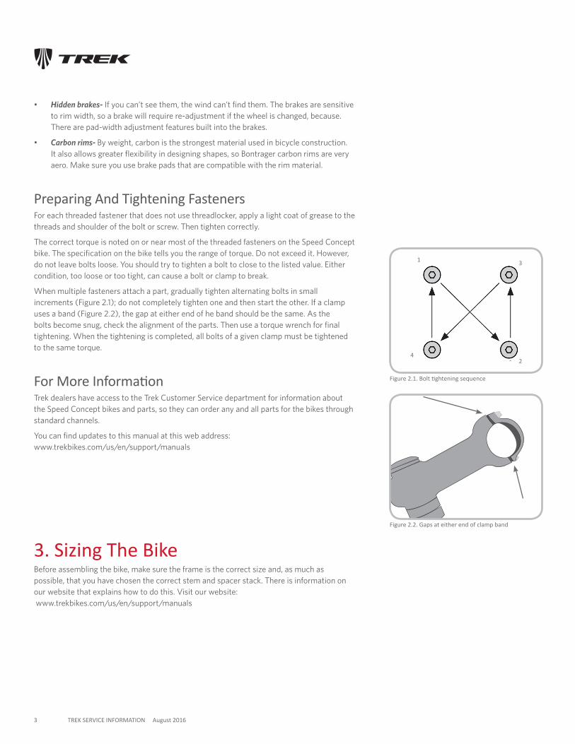
When multiple fasteners attach a part, gradually tighten alternating bolts in small increments (Figure 2.1); do not completely tighten one and then start the other. If a clamp uses a band (Figure 2.2), the gap at either end of he band should be the same. As the bolts become snug, check the alignment of the parts. Then use a torque wrench for final tightening. When the tightening is completed, all bolts of a given clamp must be tightened to the same torque.
For More InformationTrek dealers have access to the Trek Customer Service department for information about the Speed Concept bikes and parts, so they can order any and all parts for the bikes through standard channels.
You can find updates to this manual at this web address: www.trekbikes.com/us/en/support/manuals
3. Sizing The BikeBefore assembling the bike, make sure the frame is the correct size and, as much as possible, that you have chosen the correct stem and spacer stack. There is information on our website that explains how to do this. Visit our website: www.trekbikes.com/us/en/support/manuals
Figure 2.1. Bolt tightening sequence
Figure 2.2. Gaps at either end of clamp band
1
2
3
4
4 TREK SERVICE INFORMATION August 2016
4. Seatpost This section explain how to install the seatpost, adjust the seatpost height, and how to tilt the saddle.
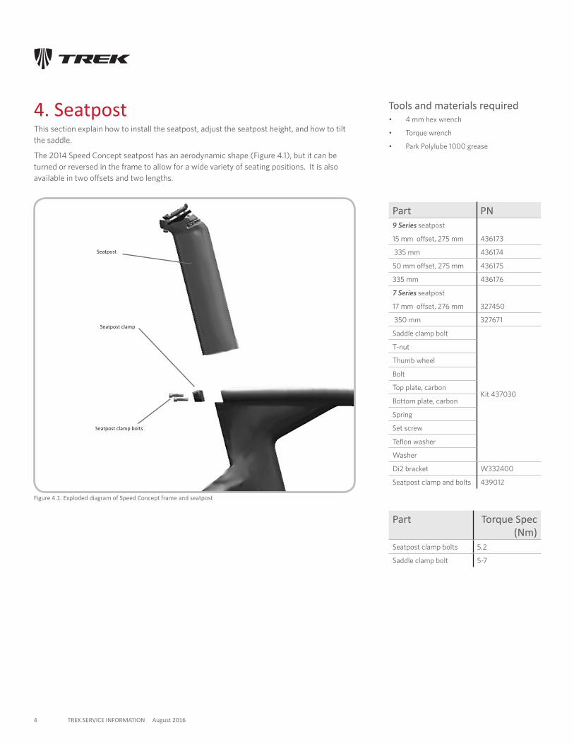
The 2014 Speed Concept seatpost has an aerodynamic shape (Figure 4.1), but it can be turned or reversed in the frame to allow for a wide variety of seating positions. It is also available in two offsets and two lengths.
Tools and materials required• 4 mm hex wrench
• Torque wrench
• Park Polylube 1000 grease
Part PN9 Series seatpost
15 mm offset, 275 mm 436173
335 mm 436174
50 mm offset, 275 mm 436175
335 mm 436176
7 Series seatpost
17 mm offset, 276 mm 327450
350 mm 327671
Saddle clamp bolt
Kit 437030
T-nut
Thumb wheel
Bolt
Top plate, carbon
Bottom plate, carbon
Spring
Set screw
Teflon washer
Washer
Di2 bracket W332400
Seatpost clamp and bolts 439012
Figure 4.1. Exploded diagram of Speed Concept frame and seatpost
Seatpost
Seatpost clamp
Seatpost clamp bolts
Part Torque Spec (Nm)
Seatpost clamp bolts 5.2
Saddle clamp bolt 5-7
5 TREK SERVICE INFORMATION August 2016
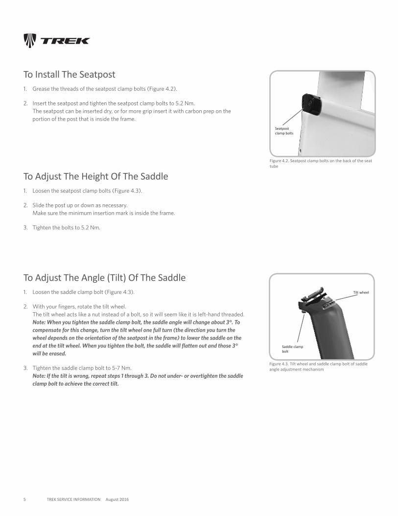
Figure 4.2. Seatpost clamp bolts on the back of the seat tube
Figure 4.3. Tilt wheel and saddle clamp bolt of saddle angle adjustment mechanism
Tilt wheel
Saddle clamp bolt
To Install The Seatpost1. Grease the threads of the seatpost clamp bolts (Figure 4.2).
2. Insert the seatpost and tighten the seatpost clamp bolts to 5.2 Nm. The seatpost can be inserted dry, or for more grip insert it with carbon prep on the portion of the post that is inside the frame.
To Adjust The Height Of The Saddle1. Loosen the seatpost clamp bolts (Figure 4.3).
2. Slide the post up or down as necessary. Make sure the minimum insertion mark is inside the frame.
3. Tighten the bolts to 5.2 Nm.
To Adjust The Angle (Tilt) Of The Saddle1. Loosen the saddle clamp bolt (Figure 4.3).
2. With your fingers, rotate the tilt wheel. The tilt wheel acts like a nut instead of a bolt, so it will seem like it is left-hand threaded. Note: When you tighten the saddle clamp bolt, the saddle angle will change about 3°. To compensate for this change, turn the tilt wheel one full turn (the direction you turn the wheel depends on the orientation of the seatpost in the frame) to lower the saddle on the end at the tilt wheel. When you tighten the bolt, the saddle will flatten out and those 3° will be erased.
3. Tighten the saddle clamp bolt to 5-7 Nm. Note: If the tilt is wrong, repeat steps 1 through 3. Do not under- or overtighten the saddle clamp bolt to achieve the correct tilt.
Seatpost clamp bolts
6 TREK SERVICE INFORMATION August 2016
5. Using A Repair StandThis section explains how to correctly put the Speed Concept in a work stand.
Do not clamp the frame. The only accepted or recommended method for holding the Speed Concept is to use the special workstand clamp adapter designed specifically to clamp the seatpost (Figure 5.1). The adapter clamps only to the seatpost, which must be installed first.
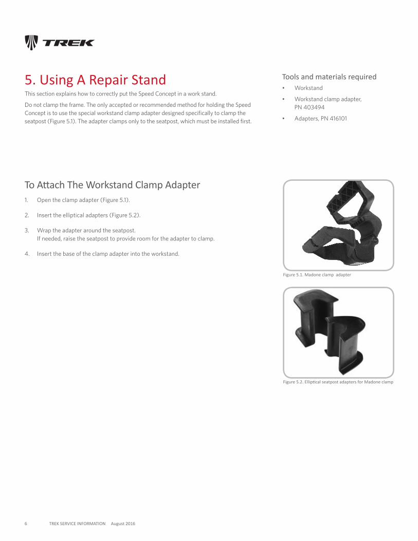
Figure 5.1. Madone clamp adapter
Tools and materials required• Workstand
• Workstand clamp adapter, PN 403494
• Adapters, PN 416101
To Attach The Workstand Clamp Adapter1. Open the clamp adapter (Figure 5.1).
2. Insert the elliptical adapters (Figure 5.2).
3. Wrap the adapter around the seatpost. If needed, raise the seatpost to provide room for the adapter to clamp.
4. Insert the base of the clamp adapter into the workstand.
Figure 5.2. Elliptical seatpost adapters for Madone clamp
7 TREK SERVICE INFORMATION August 2016
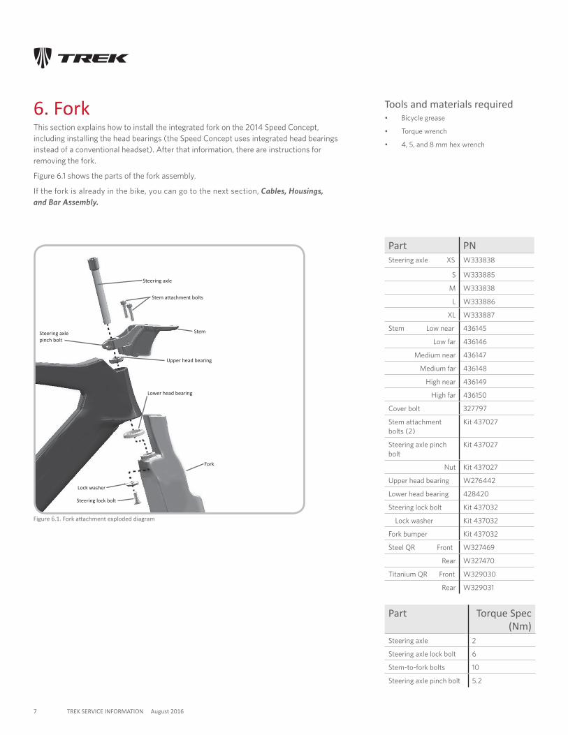
6. ForkThis section explains how to install the integrated fork on the 2014 Speed Concept, including installing the head bearings (the Speed Concept uses integrated head bearings instead of a conventional headset). After that information, there are instructions for removing the fork.
Figure 6.1 shows the parts of the fork assembly.
If the fork is already in the bike, you can go to the next section, Cables, Housings, and Bar Assembly.
Figure 6.1. Fork attachment exploded diagram
Stem
Steering axle
Upper head bearing
Lower head bearing
Fork
Lock washer
Part PNSteering axle XS W333838
S W333885
M W333838
L W333886
XL W333887
Stem Low near 436145
Low far 436146
Medium near 436147
Medium far 436148
High near 436149
High far 436150
Cover bolt 327797
Stem attachment bolts (2)
Kit 437027
Steering axle pinch bolt
Kit 437027
Nut Kit 437027
Upper head bearing W276442
Lower head bearing 428420
Steering lock bolt Kit 437032
Lock washer Kit 437032
Fork bumper Kit 437032
Steel QR Front W327469
Rear W327470
Titanium QR Front W329030
Rear W329031
Stem attachment bolts
Steering lock bolt
Part Torque Spec (Nm)
Steering axle 2
Steering axle lock bolt 6
Stem-to-fork bolts 10
Steering axle pinch bolt 5.2
Steering axle pinch bolt
Tools and materials required• Bicycle grease
• Torque wrench
• 4, 5, and 8 mm hex wrench
8 TREK SERVICE INFORMATION August 2016
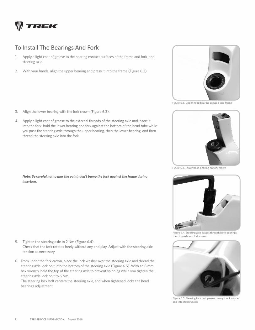
To Install The Bearings And Fork1. Apply a light coat of grease to the bearing contact surfaces of the frame and fork, and
steering axle.
2. With your hands, align the upper bearing and press it into the frame (Figure 6.2).
3. Align the lower bearing with the fork crown (Figure 6.3).
4. Apply a light coat of grease to the external threads of the steering axle and insert it into the fork: hold the lower bearing and fork against the bottom of the head tube while you pass the steering axle through the upper bearing, then the lower bearing, and then thread the steering axle into the fork.
Note: Be careful not to mar the paint; don’t bump the fork against the frame during insertion.
Figure 6.5. Steering lock bolt passes through lock washer and into steering axle
5. Tighten the steering axle to 2 Nm (Figure 6.4). Check that the fork rotates freely without any end play. Adjust with the steering axle tension as necessary.
6. From under the fork crown, place the lock washer over the steering axle and thread the steering axle lock bolt into the bottom of the steering axle (Figure 6.5). With an 8 mm hex wrench, hold the top of the steering axle to prevent spinning while you tighten the steering axle lock bolt to 6 Nm.. The steering lock bolt centers the steering axle, and when tightened locks the head bearings adjustment.
Figure 6.3. Lower head bearing on fork crown
Figure 6.4. Steering axle passes through both bearings, then threads into fork crown
Figure 6.2. Upper head bearing pressed into frame
9 TREK SERVICE INFORMATION August 2016
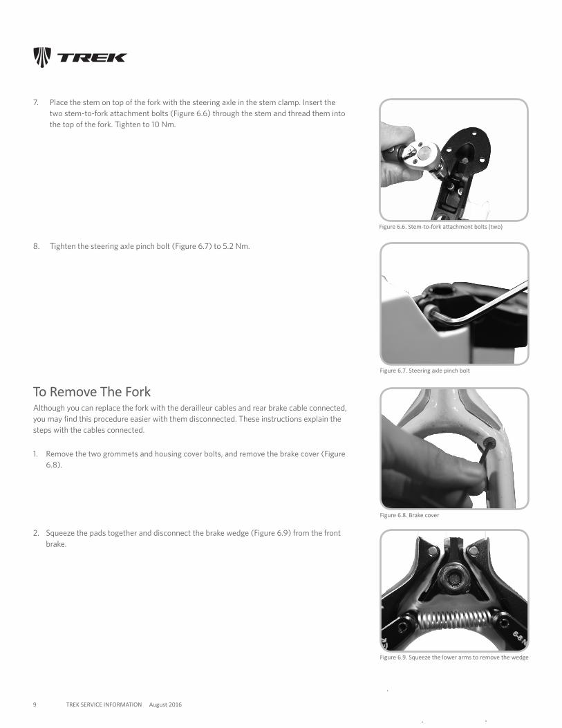
To Remove The ForkAlthough you can replace the fork with the derailleur cables and rear brake cable connected, you may find this procedure easier with them disconnected. These instructions explain the steps with the cables connected.
2. Squeeze the pads together and disconnect the brake wedge (Figure 6.9) from the front brake.
Figure 6.8. Brake cover
1. Remove the two grommets and housing cover bolts, and remove the brake cover (Figure 6.8).
Figure 6.7. Steering axle pinch bolt
7. Place the stem on top of the fork with the steering axle in the stem clamp. Insert the two stem-to-fork attachment bolts (Figure 6.6) through the stem and thread them into the top of the fork. Tighten to 10 Nm.
Figure 6.9. Squeeze the lower arms to remove the wedge
Figure 6.6. Stem-to-fork attachment bolts (two)
8. Tighten the steering axle pinch bolt (Figure 6.7) to 5.2 Nm.
10 TREK SERVICE INFORMATION August 2016
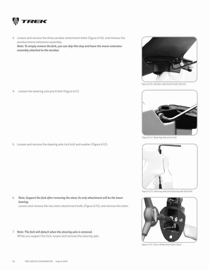
3. Loosen and remove the three aerobar attachment bolts (Figure 6.10), and remove the aerobar/mono-extension assembly. Note: To simply remove the fork, you can skip this step and leave the mono-extension assembly attached to the aerobar.
4. Loosen the steering axle pinch bolt (Figure 6.11).
Figure 6.11. Steering axle pinch bolt
Figure 6.13. Stem attachment bolts (two)
5. Loosen and remove the steering axle lock bolt and washer (Figure 6.12).
6. Note: Support the fork after removing the stem; its only attachment will be the lower bearing. Loosen and remove the two stem attachment bolts (Figure 6.13), and remove the stem.
Figure 6.12. Steering axle and steering axle lock bolt
Figure 6.10. Aerobar attachment bolts (three)
7. Note: The fork will detach when the steering axle is removed. While you support the fork, loosen and remove the steering axle.
11 TREK SERVICE INFORMATION August 2016
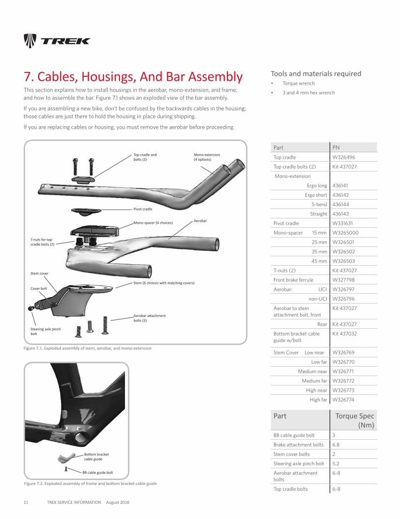
7. Cables, Housings, And Bar AssemblyThis section explains how to install housings in the aerobar, mono-extension, and frame; and how to assemble the bar. Figure 7.1 shows an exploded view of the bar assembly.
If you are assembling a new bike, don’t be confused by the backwards cables in the housing; those cables are just there to hold the housing in place during shipping.
If you are replacing cables or housing, you must remove the aerobar before proceeding.
Tools and materials required• Torque wrench
• 3 and 4 mm hex wrench
Figure 7.1. Exploded assembly of stem, aerobar, and mono-extension
Mono-extension (4 options)
Top cradle and bolts (2)
Pivot cradle
Mono-spacer (4 choices) Aerobar
Stem (6 choices with matching covers)
Part PN
Top cradle W326496
Top cradle bolts (2) Kit 437027
Mono-extension
Ergo long 436141
Ergo short 436142
S-bend 436144
Straight 436143
Pivot cradle W331631
Mono-spacer 15 mm W3265000
25 mm W326501
35 mm W326502
45 mm W326503
T-nuts (2) Kit 437027
Front brake ferrule W327798
Aerobar: UCI W326797
non-UCI W326796
Aerobar to stem attachment bolt, front
Kit 437027
Rear Kit 437027
Bottom bracket cable guide w/bolt
Kit 437032
Stem Cover Low near W326769
Low far W326770
Medium near W326771
Medium far W326772
High near W326773
High far W326774
Aerobar attachment bolts (3)
Figure 7.2. Exploded assembly of frame and bottom bracket cable guide
T-nuts for top cradle bolts (2)
Stem cover
Steering axle pinch bolt
Part Torque Spec (Nm)
BB cable guide bolt 3
Brake attachment bolts 6.8
Stem cover bolts 2
Steering axle pinch bolt 5.2
Aerobar attachment bolts
6-8
Top cradle bolts 6-8
Cover bolt
BB cable guide bolt
Bottom bracket cable guide
12 TREK SERVICE INFORMATION August 2016
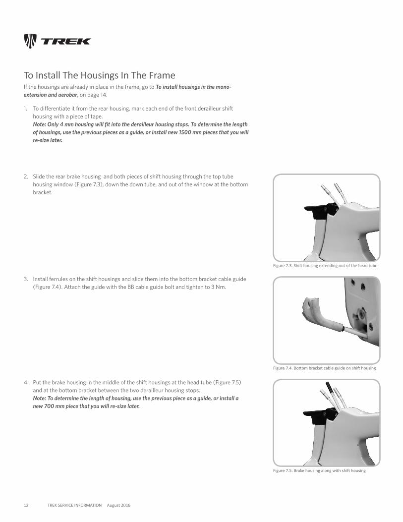
To Install The Housings In The FrameIf the housings are already in place in the frame, go to To install housings in the mono-extension and aerobar, on page 14.
1. To differentiate it from the rear housing, mark each end of the front derailleur shift housing with a piece of tape. Note: Only 4 mm housing will fit into the derailleur housing stops. To determine the length of housings, use the previous pieces as a guide, or install new 1500 mm pieces that you will re-size later.
Figure 7.3. Shift housing extending out of the head tube
2. Slide the rear brake housing and both pieces of shift housing through the top tube housing window (Figure 7.3), down the down tube, and out of the window at the bottom bracket.
Figure 7.4. Bottom bracket cable guide on shift housing
Figure 7.5. Brake housing along with shift housing
3. Install ferrules on the shift housings and slide them into the bottom bracket cable guide (Figure 7.4). Attach the guide with the BB cable guide bolt and tighten to 3 Nm.
4. Put the brake housing in the middle of the shift housings at the head tube (Figure 7.5) and at the bottom bracket between the two derailleur housing stops. Note: To determine the length of housing, use the previous piece as a guide, or install a new 700 mm piece that you will re-size later.
13 TREK SERVICE INFORMATION August 2016
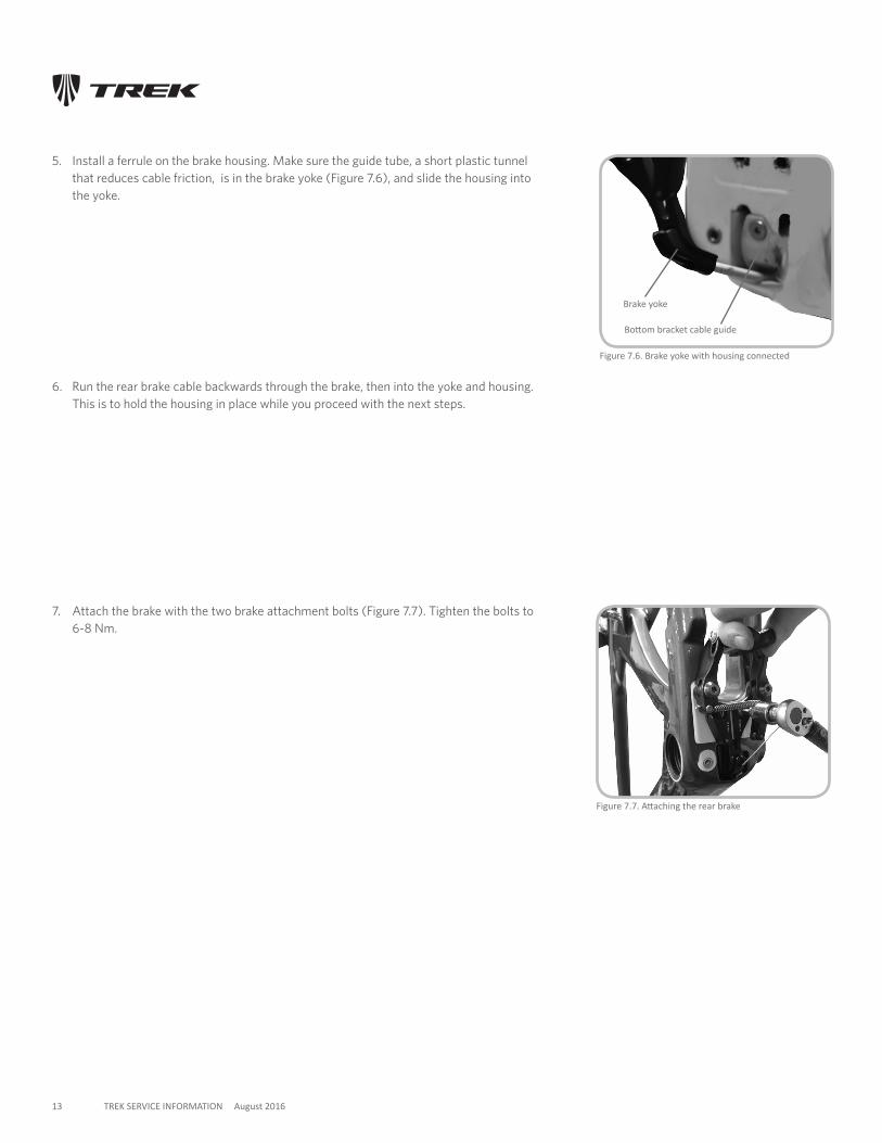
Figure 7.6. Brake yoke with housing connected
5. Install a ferrule on the brake housing. Make sure the guide tube, a short plastic tunnel that reduces cable friction, is in the brake yoke (Figure 7.6), and slide the housing into the yoke.
6. Run the rear brake cable backwards through the brake, then into the yoke and housing. This is to hold the housing in place while you proceed with the next steps.
Figure 7.7. Attaching the rear brake
7. Attach the brake with the two brake attachment bolts (Figure 7.7). Tighten the bolts to 6-8 Nm.
Brake yoke
Bottom bracket cable guide
14 TREK SERVICE INFORMATION August 2016
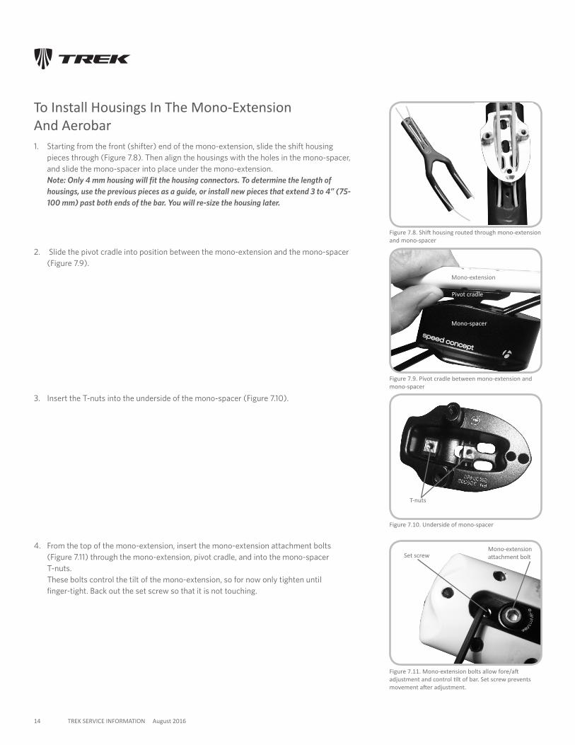
Figure 7.8. Shift housing routed through mono-extension and mono-spacer
Figure 7.9. Pivot cradle between mono-extension and mono-spacer
To Install Housings In The Mono-Extension And Aerobar1. Starting from the front (shifter) end of the mono-extension, slide the shift housing
pieces through (Figure 7.8). Then align the housings with the holes in the mono-spacer, and slide the mono-spacer into place under the mono-extension. Note: Only 4 mm housing will fit the housing connectors. To determine the length of housings, use the previous pieces as a guide, or install new pieces that extend 3 to 4” (75-100 mm) past both ends of the bar. You will re-size the housing later.
2. Slide the pivot cradle into position between the mono-extension and the mono-spacer (Figure 7.9).
3. Insert the T-nuts into the underside of the mono-spacer (Figure 7.10).
4. From the top of the mono-extension, insert the mono-extension attachment bolts (Figure 7.11) through the mono-extension, pivot cradle, and into the mono-spacer T-nuts. These bolts control the tilt of the mono-extension, so for now only tighten until finger-tight. Back out the set screw so that it is not touching.
Figure 7.10. Underside of mono-spacer
Figure 7.11. Mono-extension bolts allow fore/aft adjustment and control tilt of bar. Set screw prevents movement after adjustment.
Set screwMono-extension attachment bolt
Mono-extension
Mono-spacer
Pivot cradle
T-nuts
15 TREK SERVICE INFORMATION August 2016
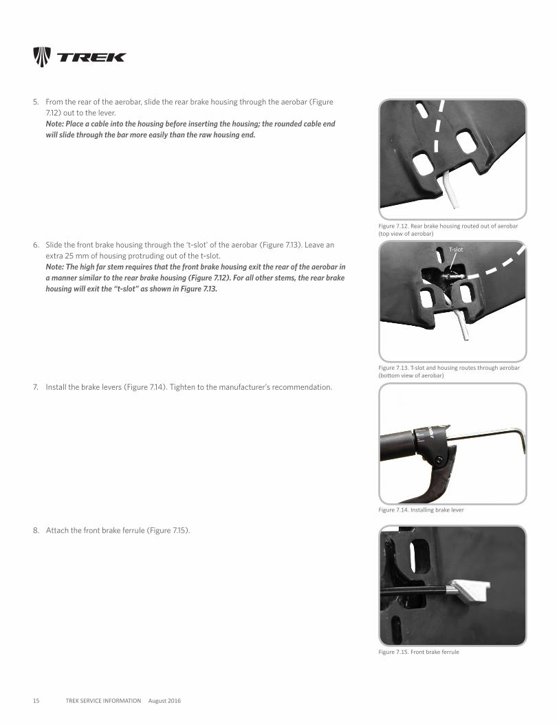
5. From the rear of the aerobar, slide the rear brake housing through the aerobar (Figure 7.12) out to the lever. Note: Place a cable into the housing before inserting the housing; the rounded cable end will slide through the bar more easily than the raw housing end.
Figure 7.15. Front brake ferrule
6. Slide the front brake housing through the ‘t-slot’ of the aerobar (Figure 7.13). Leave an extra 25 mm of housing protruding out of the t-slot. Note: The high far stem requires that the front brake housing exit the rear of the aerobar in a manner similar to the rear brake housing (Figure 7.12). For all other stems, the rear brake housing will exit the “t-slot” as shown in Figure 7.13.
7. Install the brake levers (Figure 7.14). Tighten to the manufacturer’s recommendation.
8. Attach the front brake ferrule (Figure 7.15).
Figure 7.14. Installing brake lever
Figure 7.12. Rear brake housing routed out of aerobar (top view of aerobar)
Figure 7.13. T-slot and housing routes through aerobar (bottom view of aerobar)
T-slot
16 TREK SERVICE INFORMATION August 2016
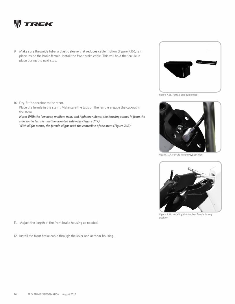
9. Make sure the guide tube, a plastic sleeve that reduces cable friction (Figure 7.16), is in place inside the brake ferrule. Install the front brake cable. This will hold the ferrule in place during the next step.
11. Adjust the length of the front brake housing as needed.
12. Install the front brake cable through the lever and aerobar housing.
Figure 7.17. Ferrule in sideways position
10. Dry-fit the aerobar to the stem. Place the ferrule in the stem . Make sure the tabs on the ferrule engage the cut-out in the stem. Note: With the low near, medium near, and high near stems, the housing comes in from the side so the ferrule must be oriented sideways (Figure 7.17). With all far stems, the ferrule aligns with the centerline of the stem (Figure 7.18).
Figure 7.18. Installing the aerobar, ferrule in long position
Figure 7.16. Ferrule and guide tube
17 TREK SERVICE INFORMATION August 2016
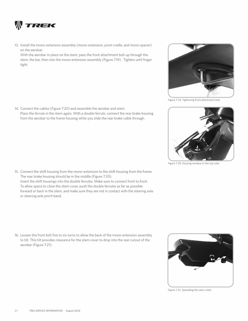
13. Install the mono-extension assembly (mono-extension, pivot cradle, and mono-spacer) on the aerobar. With the aerobar in place on the stem, pass the front attachment bolt up through the stem, the bar, then into the mono-extension assembly (Figure 7.19). Tighten until finger tight.
14. Connect the cables (Figure 7.20) and assemble the aerobar and stem. Place the ferrule in the stem again. With a double ferrule, connect the rear brake housing from the aerobar to the frame housing while you slide the rear brake cable through.
15. Connect the shift housing from the mono-extension to the shift housing from the frame. The rear brake housing should be in the middle (Figure 7.20). Insert the shift housings into the double ferrules. Make sure to connect front to front. To allow space to close the stem cover, push the double ferrules as far as possible forward or back in the stem, and make sure they are not in contact with the steering axle or steering axle pinch band.
Figure 7.19. Tightening front attachment bolt
16. Loosen the front bolt five to six turns to allow the back of the mono-extension assembly to tilt. This tilt provides clearance for the stem cover to drop into the rear cutout of the aerobar (Figure 7.21).
Figure 7.20. Housing window in the top tube
Figure 7.21. Spreading the stem cover
18 TREK SERVICE INFORMATION August 2016
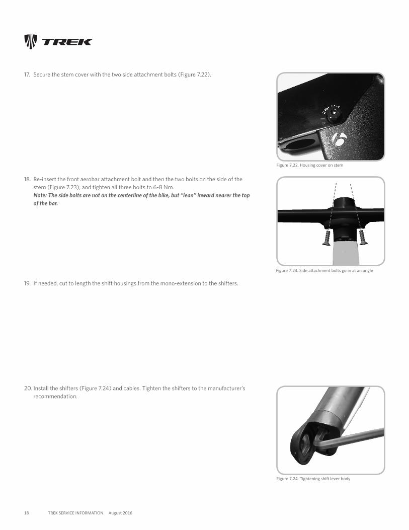
18. Re-insert the front aerobar attachment bolt and then the two bolts on the side of the stem (Figure 7.23), and tighten all three bolts to 6-8 Nm. Note: The side bolts are not on the centerline of the bike, but “lean” inward nearer the top of the bar.
17. Secure the stem cover with the two side attachment bolts (Figure 7.22).
Figure 7.23. Side attachment bolts go in at an angle
Figure 7.24. Tightening shift lever body
19. If needed, cut to length the shift housings from the mono-extension to the shifters.
Figure 7.22. Housing cover on stem
20. Install the shifters (Figure 7.24) and cables. Tighten the shifters to the manufacturer’s recommendation.
19 TREK SERVICE INFORMATION August 2016
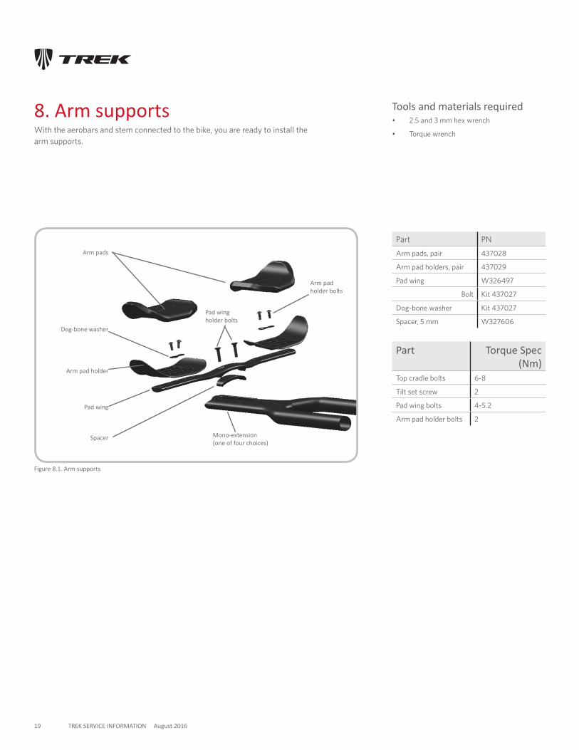
8. Arm supportsWith the aerobars and stem connected to the bike, you are ready to install the arm supports.
Part PN
Arm pads, pair 437028
Arm pad holders, pair 437029
Pad wing W326497
Bolt Kit 437027
Dog-bone washer Kit 437027
Spacer, 5 mm W327606
Figure 8.1. Arm supports
Mono-extension (one of four choices)
Arm pads
Arm pad holder
Pad wing
Dog-bone washer
Spacer
Part Torque Spec (Nm)
Top cradle bolts 6-8
Tilt set screw 2
Pad wing bolts 4-5.2
Arm pad holder bolts 2
Arm pad holder bolts
Pad wing holder bolts
Tools and materials required• 2.5 and 3 mm hex wrench
• Torque wrench
20 TREK SERVICE INFORMATION August 2016
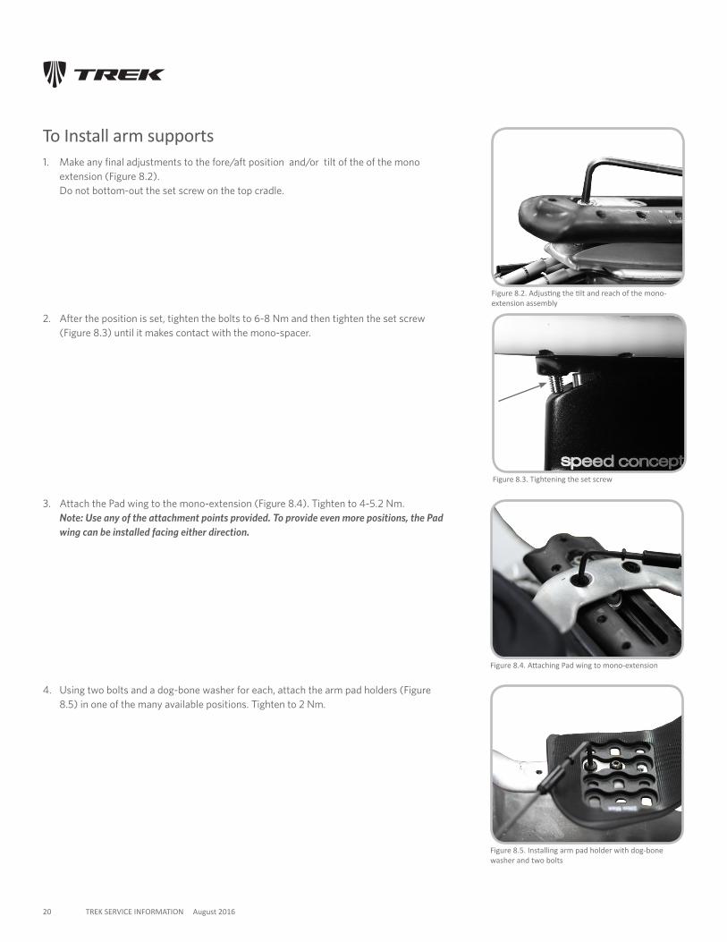
To Install arm supports1. Make any final adjustments to the fore/aft position and/or tilt of the of the mono
extension (Figure 8.2). Do not bottom-out the set screw on the top cradle.
Figure 8.4. Attaching Pad wing to mono-extension
Figure 8.5. Installing arm pad holder with dog-bone washer and two bolts
2. After the position is set, tighten the bolts to 6-8 Nm and then tighten the set screw (Figure 8.3) until it makes contact with the mono-spacer.
3. Attach the Pad wing to the mono-extension (Figure 8.4). Tighten to 4-5.2 Nm. Note: Use any of the attachment points provided. To provide even more positions, the Pad wing can be installed facing either direction.
4. Using two bolts and a dog-bone washer for each, attach the arm pad holders (Figure 8.5) in one of the many available positions. Tighten to 2 Nm.
Figure 8.3. Tightening the set screw
Figure 8.2. Adjusting the tilt and reach of the mono-extension assembly
21 TREK SERVICE INFORMATION August 2016
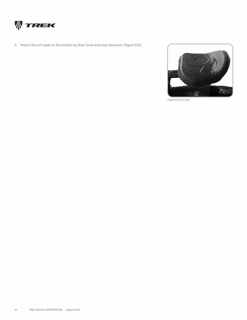
Figure 8.6 Arm pad
5. Attach the arm pads to the holders by their hook-and-loop fasteners (Figure 8.6).
22 TREK SERVICE INFORMATION August 2016
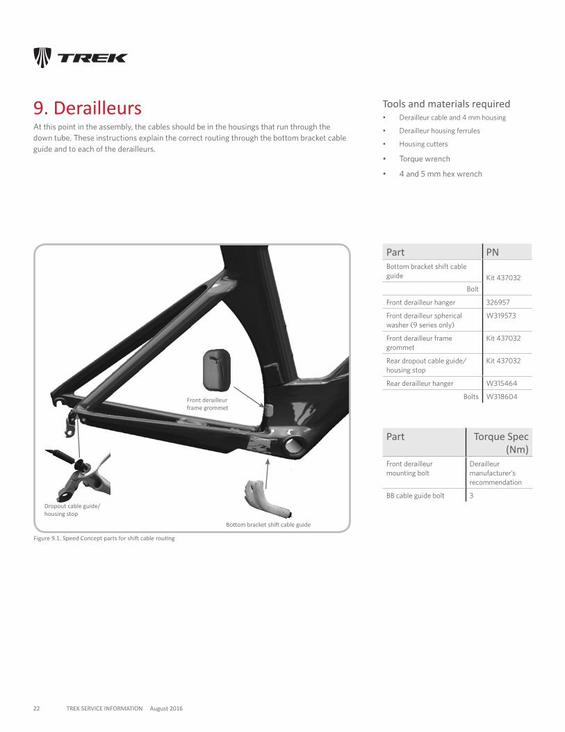
9. Derailleurs At this point in the assembly, the cables should be in the housings that run through the down tube. These instructions explain the correct routing through the bottom bracket cable guide and to each of the derailleurs.
Figure 9.1. Speed Concept parts for shift cable routing
Part PNBottom bracket shift cable guide Kit 437032
Bolt
Front derailleur hanger 326957
Front derailleur spherical washer (9 series only)
W319573
Front derailleur frame grommet
Kit 437032
Rear dropout cable guide/ housing stop
Kit 437032
Rear derailleur hanger W315464
Bolts W318604
Dropout cable guide/ housing stop
Bottom bracket shift cable guide
Front derailleur frame grommet
Part Torque Spec (Nm)
Front derailleur mounting bolt
Derailleur manufacturer’s recommendation
BB cable guide bolt 3
Tools and materials required• Derailleur cable and 4 mm housing
• Derailleur housing ferrules
• Housing cutters
• Torque wrench
• 4 and 5 mm hex wrench
23 TREK SERVICE INFORMATION August 2016
Figure 9.4. Seat tube grommet on cable liner to front derailleur
Figure 9.5. Rear derailleur cable passing through the dropout housing stop
Figure 9.3. Correct orientation of seat tube grommet
Drive side
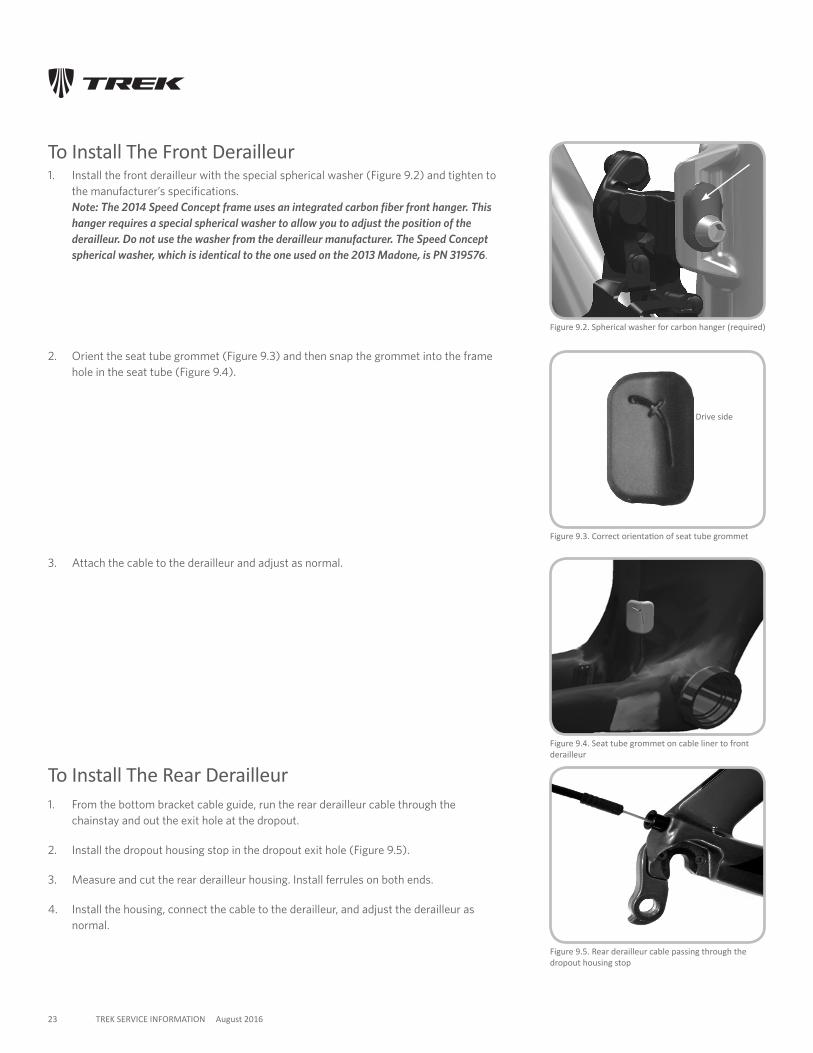
To Install The Front Derailleur
1. Install the front derailleur with the special spherical washer (Figure 9.2) and tighten to the manufacturer’s specifications. Note: The 2014 Speed Concept frame uses an integrated carbon fiber front hanger. This hanger requires a special spherical washer to allow you to adjust the position of the derailleur. Do not use the washer from the derailleur manufacturer. The Speed Concept spherical washer, which is identical to the one used on the 2013 Madone, is PN 319576.
2. Orient the seat tube grommet (Figure 9.3) and then snap the grommet into the frame hole in the seat tube (Figure 9.4).
Figure 9.2. Spherical washer for carbon hanger (required)
3. Attach the cable to the derailleur and adjust as normal.
To Install The Rear Derailleur1. From the bottom bracket cable guide, run the rear derailleur cable through the
chainstay and out the exit hole at the dropout.
2. Install the dropout housing stop in the dropout exit hole (Figure 9.5).
3. Measure and cut the rear derailleur housing. Install ferrules on both ends.
4. Install the housing, connect the cable to the derailleur, and adjust the derailleur as normal.
24 TREK SERVICE INFORMATION August 2016
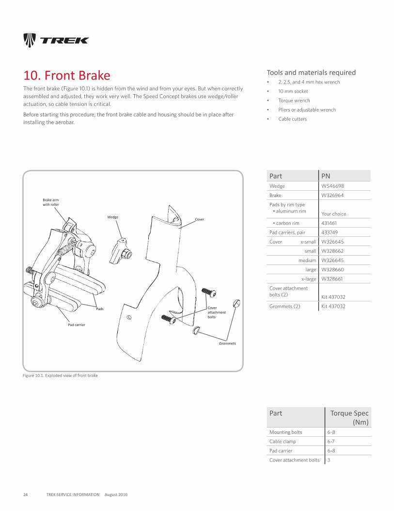
Figure 10.1. Exploded view of front brake
10. Front BrakeThe front brake (Figure 10.1) is hidden from the wind and from your eyes. But when correctly assembled and adjusted, they work very well. The Speed Concept brakes use wedge/roller actuation, so cable tension is critical.
Before starting this procedure, the front brake cable and housing should be in place after installing the aerobar.
Part PNWedge W546698
Brake W326964
Pads by rim type • aluminum rim Your choice
• carbon rim 431461
Pad carriers, pair 433749
Cover x-small W326645
small W328662
medium W326645
large W328660
x-large W328661
Cover attachment bolts (2) Kit 437032
Grommets (2) Kit 437032
Wedge
Brake arm with roller
Cover
Cover attachment bolts
Grommets
Pad carrier
Pads
Part Torque Spec (Nm)
Mounting bolts 6-8
Cable clamp 6-7
Pad carrier 6-8
Cover attachment bolts 3
Tools and materials required• 2, 2.5, and 4 mm hex wrench
• 10 mm socket
• Torque wrench
• Pliers or adjustable wrench
• Cable cutters
25 TREK SERVICE INFORMATION August 2016
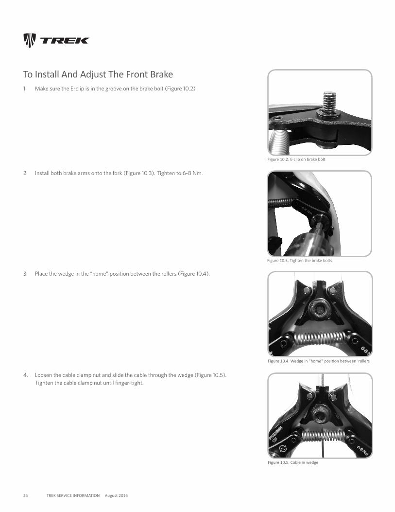
To Install And Adjust The Front Brake1. Make sure the E-clip is in the groove on the brake bolt (Figure 10.2)
Figure 10.2. E-clip on brake bolt
Figure 10.3. Tighten the brake bolts
2. Install both brake arms onto the fork (Figure 10.3). Tighten to 6-8 Nm.
3. Place the wedge in the “home” position between the rollers (Figure 10.4).
Figure 10.4. Wedge in “home” position between rollers
4. Loosen the cable clamp nut and slide the cable through the wedge (Figure 10.5). Tighten the cable clamp nut until finger-tight.
Figure 10.5. Cable in wedge
26 TREK SERVICE INFORMATION August 2016
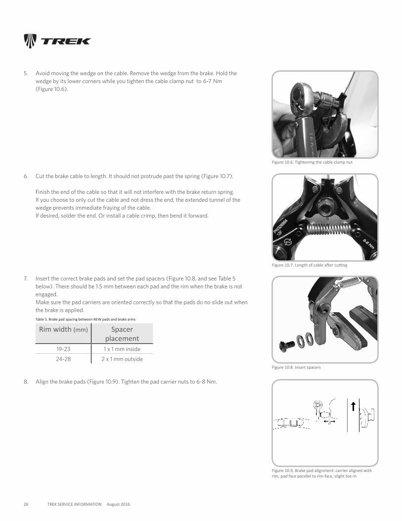
5. Avoid moving the wedge on the cable. Remove the wedge from the brake. Hold the wedge by its lower corners while you tighten the cable clamp nut to 6-7 Nm (Figure 10.6).
Figure 10.6. Tightening the cable clamp nut
6. Cut the brake cable to length. It should not protrude past the spring (Figure 10.7). Finish the end of the cable so that it will not interfere with the brake return spring. If you choose to only cut the cable and not dress the end, the extended tunnel of the wedge prevents immediate fraying of the cable. If desired, solder the end. Or install a cable crimp, then bend it forward.
Figure 10.7. Length of cable after cutting
7. Insert the correct brake pads and set the pad spacers (Figure 10.8, and see Table 5 below). There should be 1.5 mm between each pad and the rim when the brake is not engaged. Make sure the pad carriers are oriented correctly so that the pads do no slide out when the brake is applied.
Table 5. Brake pad spacing between NEW pads and brake arms
Rim width (mm) Spacer placement
19-23 1 x 1 mm inside
24-28 2 x 1 mm outside
8. Align the brake pads (Figure 10.9). Tighten the pad carrier nuts to 6-8 Nm.
Figure 10.8. Insert spacers
Figure 10.9. Brake pad alignment: carrier aligned with rim, pad face parallel to rim face, slight toe-in
27 TREK SERVICE INFORMATION August 2016
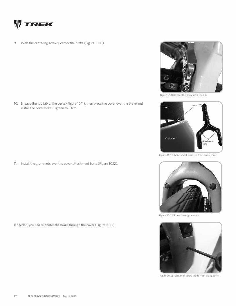
Figure 10.11. Attachment points of front brake cover
Tab
Attachment bolts
9. With the centering screws, center the brake (Figure 10.10).
10. Engage the top tab of the cover (Figure 10.11), then place the cover over the brake and install the cover bolts. Tighten to 3 Nm.
Figure 10.12. Brake cover grommets
Figure 10.13. Centering screw inside front brake cover
11. Install the grommets over the cover attachment bolts (Figure 10.12).
Brake cover
Fork
If needed, you can re-center the brake through the cover (Figure 10.13).
Figure 10.10 Center the brake over the rim
28 TREK SERVICE INFORMATION 14 February 2013
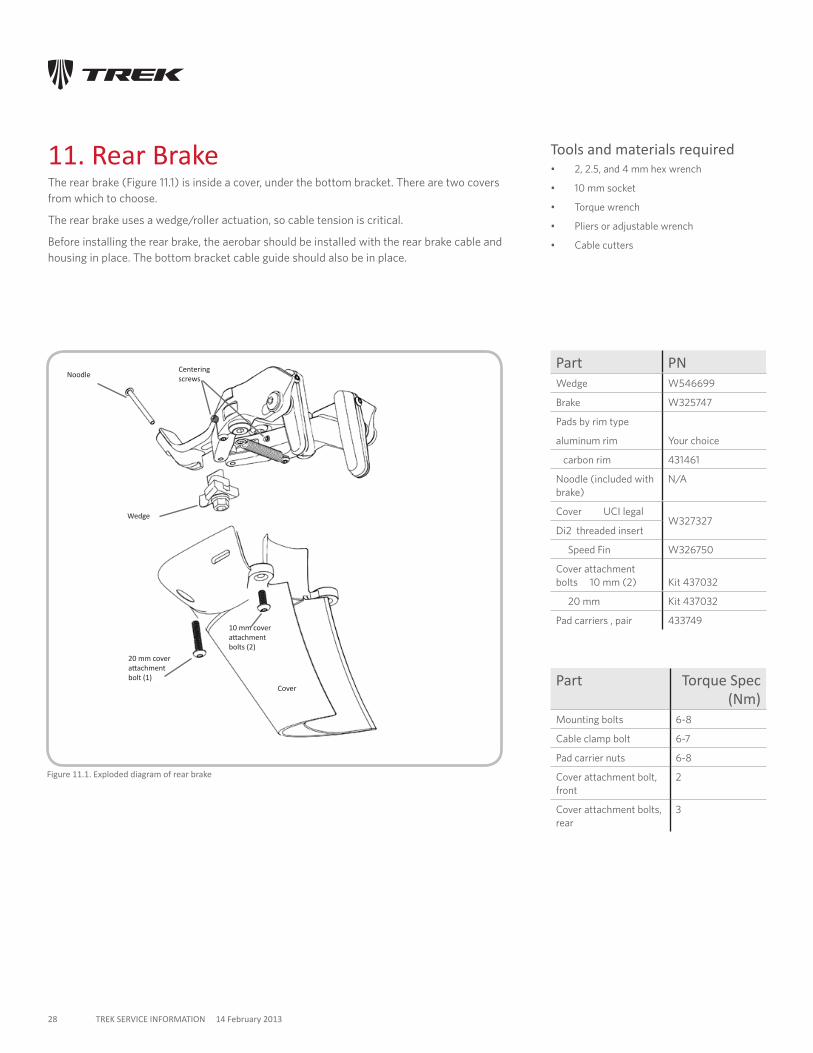
11. Rear BrakeThe rear brake (Figure 11.1) is inside a cover, under the bottom bracket. There are two covers from which to choose.
The rear brake uses a wedge/roller actuation, so cable tension is critical.
Before installing the rear brake, the aerobar should be installed with the rear brake cable and housing in place. The bottom bracket cable guide should also be in place.
Figure 11.1. Exploded diagram of rear brake
Noodle
Wedge
Cover
10 mm cover attachment bolts (2)
Part PNWedge W546699
Brake W325747
Pads by rim type
aluminum rim Your choice
carbon rim 431461
Noodle (included with brake)
N/A
Cover UCI legalW327327
Di2 threaded insert
Speed Fin W326750
Cover attachment bolts 10 mm (2)
Kit 437032
20 mm Kit 437032
Pad carriers , pair 433749
20 mm cover attachment bolt (1)
Centering screws
Part Torque Spec (Nm)
Mounting bolts 6-8
Cable clamp bolt 6-7
Pad carrier nuts 6-8
Cover attachment bolt, front
2
Cover attachment bolts, rear
3
Tools and materials required• 2, 2.5, and 4 mm hex wrench
• 10 mm socket
• Torque wrench
• Pliers or adjustable wrench
• Cable cutters
29 TREK SERVICE INFORMATION August 2016
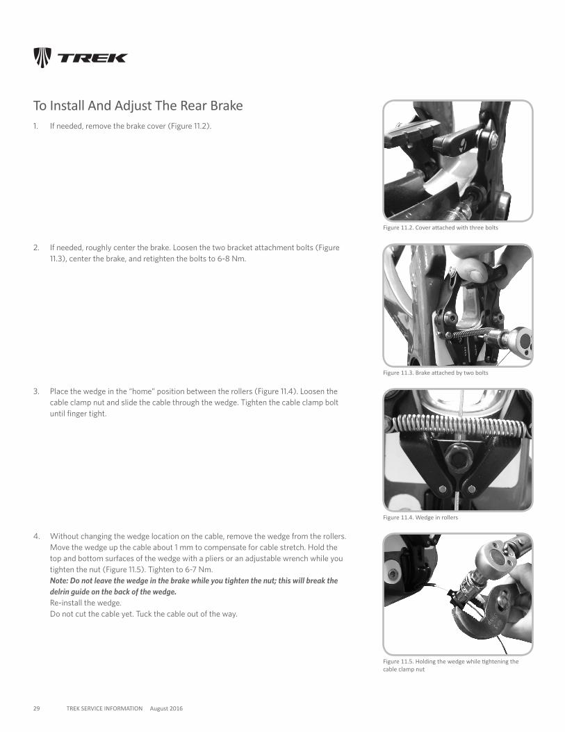
To Install And Adjust The Rear Brake1. If needed, remove the brake cover (Figure 11.2).
Figure 11.4. Wedge in rollers
2. If needed, roughly center the brake. Loosen the two bracket attachment bolts (Figure 11.3), center the brake, and retighten the bolts to 6-8 Nm.
3. Place the wedge in the “home” position between the rollers (Figure 11.4). Loosen the cable clamp nut and slide the cable through the wedge. Tighten the cable clamp bolt until finger tight.
4. Without changing the wedge location on the cable, remove the wedge from the rollers. Move the wedge up the cable about 1 mm to compensate for cable stretch. Hold the top and bottom surfaces of the wedge with a pliers or an adjustable wrench while you tighten the nut (Figure 11.5). Tighten to 6-7 Nm. Note: Do not leave the wedge in the brake while you tighten the nut; this will break the delrin guide on the back of the wedge. Re-install the wedge. Do not cut the cable yet. Tuck the cable out of the way.
Figure 11.3. Brake attached by two bolts
Figure 11.5. Holding the wedge while tightening the cable clamp nut
Figure 11.2. Cover attached with three bolts
30 TREK SERVICE INFORMATION August 2016
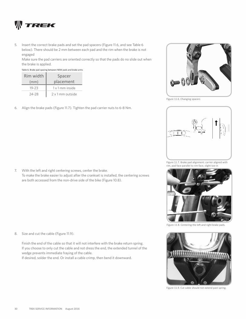
5. Insert the correct brake pads and set the pad spacers (Figure 11.6, and see Table 6 below). There should be 2 mm between each pad and the rim when the brake is not engaged Make sure the pad carriers are oriented correctly so that the pads do no slide out when the brake is applied.
Table 6. Brake pad spacing between NEW pads and brake arms
Rim width (mm)
Spacer placement
19-23 1 x 1 mm inside
24-28 2 x 1 mm outside
6. Align the brake pads (Figure 11.7). Tighten the pad carrier nuts to 6-8 Nm.
7. With the left and right centering screws, center the brake. To make the brake easier to adjust after the crankset is installed, the centering screws are both accessed from the non-drive side of the bike (Figure 10.8).
Figure 11.6. Changing spacers
Figure 11.9. Cut cable should not extend past spring.
8. Size and cut the cable (Figure 11.9). Finish the end of the cable so that it will not interfere with the brake return spring. If you choose to only cut the cable and not dress the end, the extended tunnel of the wedge prevents immediate fraying of the cable. If desired, solder the end. Or install a cable crimp, then bend it downward.
Figure 11.7. Brake pad alignment: carrier aligned with rim, pad face parallel to rim face, slight toe-in
Figure 11.8. Centering the left and right brake pads.
31 TREK SERVICE INFORMATION August 2016
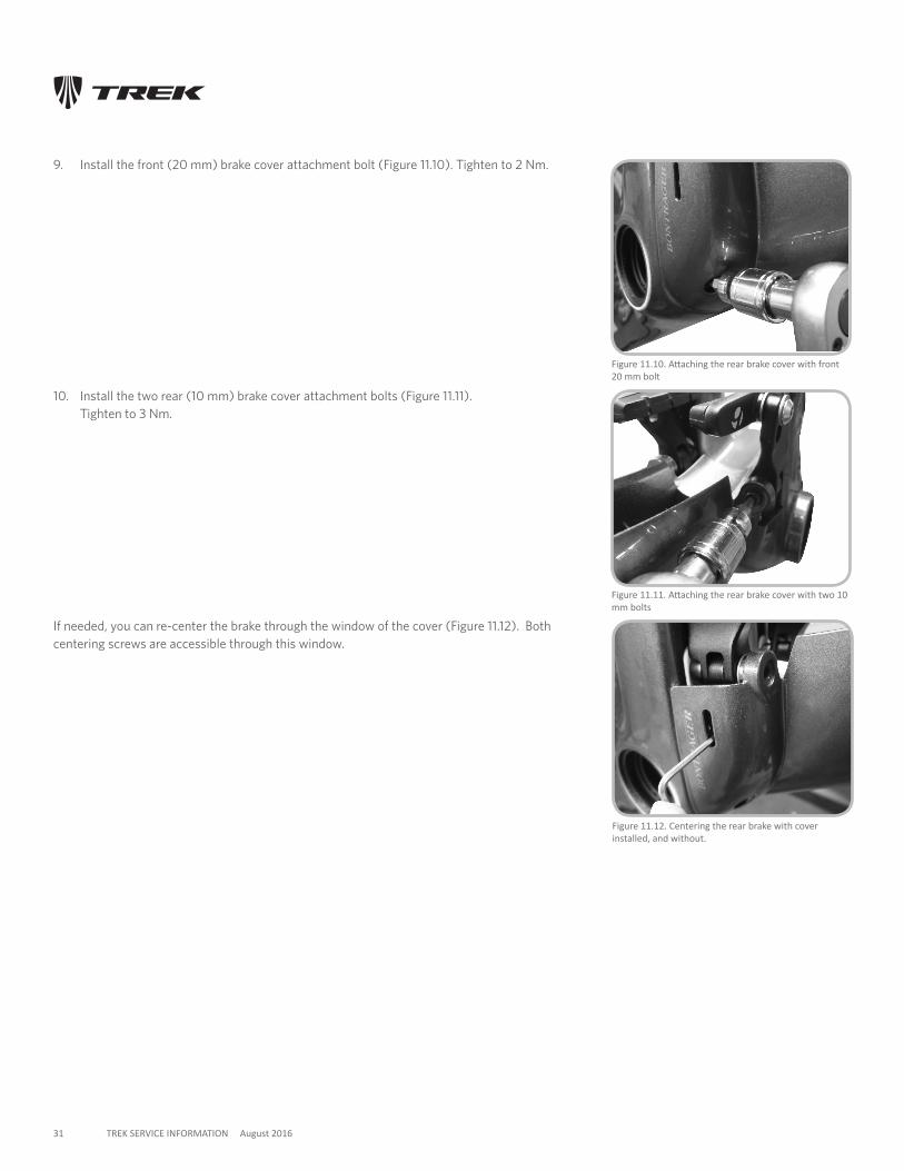
9. Install the front (20 mm) brake cover attachment bolt (Figure 11.10). Tighten to 2 Nm.
Figure 11.12. Centering the rear brake with cover installed, and without.
Figure 11.11. Attaching the rear brake cover with two 10 mm bolts
10. Install the two rear (10 mm) brake cover attachment bolts (Figure 11.11). Tighten to 3 Nm.
Figure 11.10. Attaching the rear brake cover with front 20 mm bolt
If needed, you can re-center the brake through the window of the cover (Figure 11.12). Both centering screws are accessible through this window.
32 TREK SERVICE INFORMATION August 2016
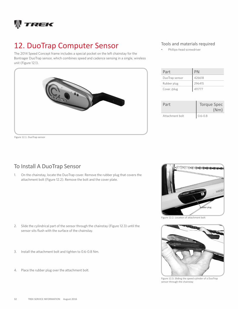
12. DuoTrap Computer SensorThe 2014 Speed Concept frame includes a special pocket on the left chainstay for the Bontrager DuoTrap sensor, which combines speed and cadence sensing in a single, wireless unit (Figure 12.1).
Figure 12.3. Sliding the speed cylinder of a DuoTrap sensor through the chainstay
Figure 12.2. Location of attachment bolt
Rubber plug
To Install A DuoTrap Sensor1. On the chainstay, locate the DuoTrap cover. Remove the rubber plug that covers the
attachment bolt (Figure 12.2). Remove the bolt and the cover plate.
2. Slide the cylindrical part of the sensor through the chainstay (Figure 12.3) until the sensor sits flush with the surface of the chainstay.
3. Install the attachment bolt and tighten to 0.6-0.8 Nm.
Figure 12.1. DuoTrap sensor
Part PNDuoTrap sensor 426618
Rubber plug 296415
Cover /plug 411777
Part Torque Spec (Nm)
Attachment bolt 0.6-0.8
Tools and materials required• Phillips-head screwdriver
4. Place the rubber plug over the attachment bolt.
33 TREK SERVICE INFORMATION August 2016
Figure 13.2. Attaching the track to the rear of the seat tube. Note orientation of spring-loaded button.
Figure 13.3. Sliding the draft box down the track
13. Accessories
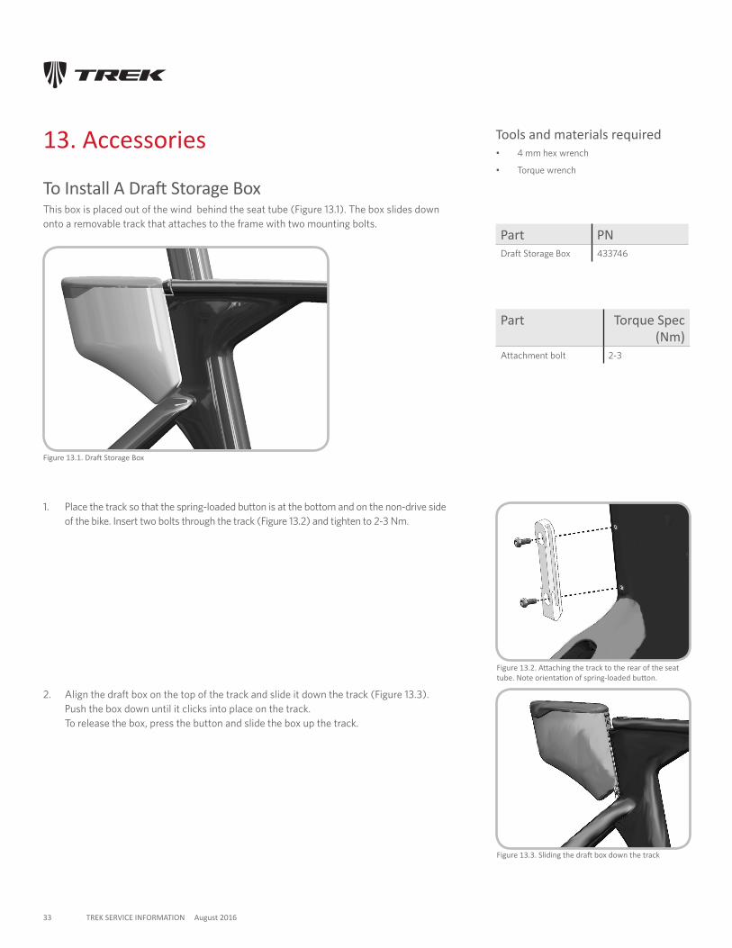
1. Place the track so that the spring-loaded button is at the bottom and on the non-drive side of the bike. Insert two bolts through the track (Figure 13.2) and tighten to 2-3 Nm.
Part PNDraft Storage Box 433746
Part Torque Spec (Nm)
Attachment bolt 2-3
To Install A Draft Storage BoxThis box is placed out of the wind behind the seat tube (Figure 13.1). The box slides down onto a removable track that attaches to the frame with two mounting bolts.
Tools and materials required• 4 mm hex wrench
• Torque wrench
2. Align the draft box on the top of the track and slide it down the track (Figure 13.3). Push the box down until it clicks into place on the track. To release the box, press the button and slide the box up the track.
Figure 13.1. Draft Storage Box
34 TREK SERVICE INFORMATION August 2016
Figure 13.4 Speed Box
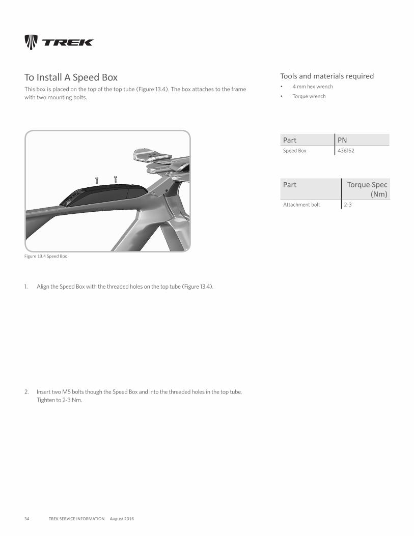
To Install A Speed BoxThis box is placed on the top of the top tube (Figure 13.4). The box attaches to the frame with two mounting bolts.
1. Align the Speed Box with the threaded holes on the top tube (Figure 13.4).
2. Insert two M5 bolts though the Speed Box and into the threaded holes in the top tube. Tighten to 2-3 Nm.
Part PNSpeed Box 436152
Part Torque Spec (Nm)
Attachment bolt 2-3
Tools and materials required• 4 mm hex wrench
• Torque wrench
35 TREK SERVICE INFORMATION August 2016
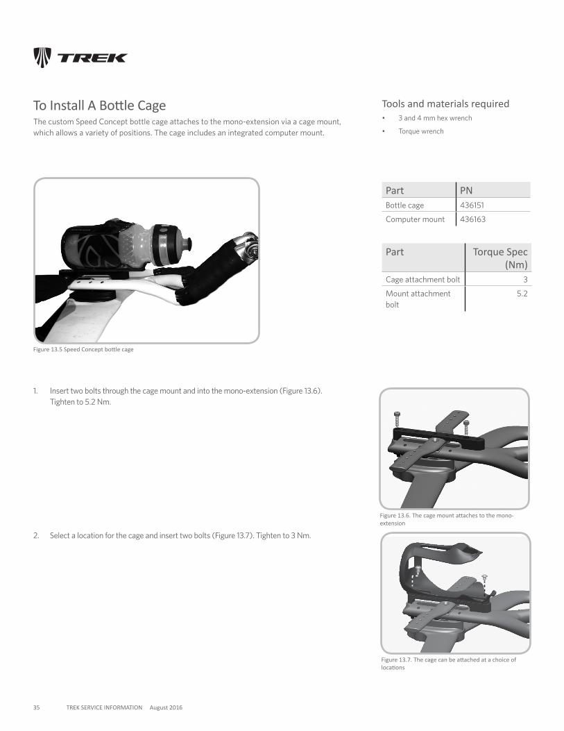
Figure 13.5 Speed Concept bottle cage
To Install A Bottle CageThe custom Speed Concept bottle cage attaches to the mono-extension via a cage mount, which allows a variety of positions. The cage includes an integrated computer mount.
1. Insert two bolts through the cage mount and into the mono-extension (Figure 13.6). Tighten to 5.2 Nm.
Figure 13.6. The cage mount attaches to the mono-extension
Figure 13.7. The cage can be attached at a choice of locations
2. Select a location for the cage and insert two bolts (Figure 13.7). Tighten to 3 Nm.
Part PNBottle cage 436151
Computer mount 436163
Part Torque Spec (Nm)
Cage attachment bolt 3
Mount attachment bolt
5.2
Tools and materials required• 3 and 4 mm hex wrench
• Torque wrench
36 TREK SERVICE INFORMATION August 2016
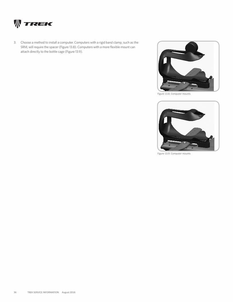
3. Choose a method to install a computer. Computers with a rigid band clamp, such as the SRM, will require the spacer (Figure 13.8). Computers with a more flexible mount can attach directly to the bottle cage (Figure 13.9).
Figure 13.9. Computer mounts
Figure 13.8. Computer mounts
37 TREK SERVICE INFORMATION August 2016
14. CranksetThe Speed Concept uses the same bearing system as a Madone; there are no parts that thread into the frame. Instead, the bearings are a slip-fit into the frame. However, the Speed Concept uses the new tighter fit of the bearings, which may require using a headset press (see page 28). Do not use a hammer to install the bearings into the frame. If the bearing fit is too tight, make sure the bearing seats are clean and free of debris.
Bearings kits are available for all major brand of cranksets: SRAM/TruVativ/Bontrager GXP, Shimano HollowTech, Campagnolo UltraTorque, and FSA MegaExo. Each kit includes a slightly different set of bearings, seals, and spacers. When installing other crankset systems, follow the manufacturer’s instructions to achieve the correct assembly and adjustment.
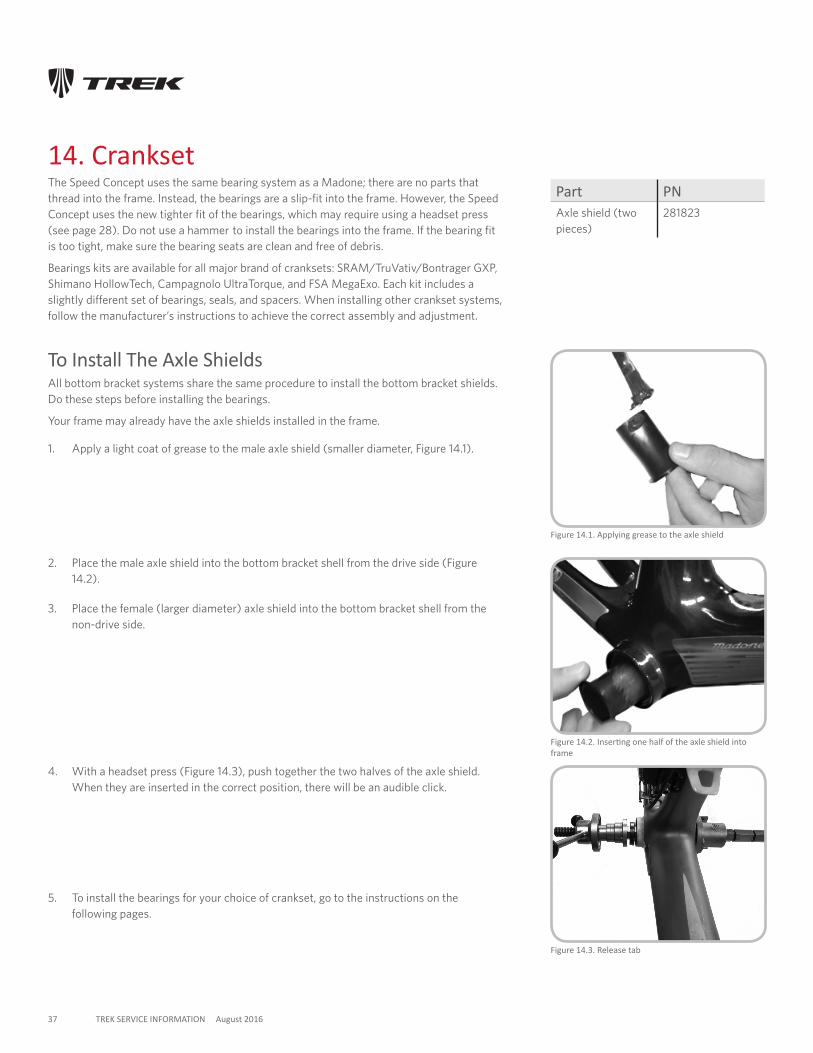
Figure 14.2. Inserting one half of the axle shield into frame
Figure 14.1. Applying grease to the axle shield
Figure 14.3. Release tab
2. Place the male axle shield into the bottom bracket shell from the drive side (Figure 14.2).
3. Place the female (larger diameter) axle shield into the bottom bracket shell from the non-drive side.
4. With a headset press (Figure 14.3), push together the two halves of the axle shield. When they are inserted in the correct position, there will be an audible click.
To Install The Axle ShieldsAll bottom bracket systems share the same procedure to install the bottom bracket shields. Do these steps before installing the bearings.
Your frame may already have the axle shields installed in the frame.
1. Apply a light coat of grease to the male axle shield (smaller diameter, Figure 14.1).
5. To install the bearings for your choice of crankset, go to the instructions on the following pages.
Part PNAxle shield (two pieces)
281823

38 TREK SERVICE INFORMATION August 2016
Pressing Crankset BearingsThe bearing fit is tighter in the Speed Concept than in early Madone models. If the bearings do not slip in by hand, follow this procedure after you have installed the bearing shield (page 28).
Notes:
• Be very careful when using the press. Too much force can crack the bottom bracket shell.
• Press in one bearing at a time.
Figure 14.5. Using a headset press to install the bearings
Tools requiredInstallation
• Park Bearing Removal Tool BBT-90
• Brass punch
• Hammer
To Press A Bearing
1. Install the bearing shield.
2. Apply a liberal coat of grease to the contact surfaces of one bearing and the drive side of the bottom bracket shell (Figure 14.4).
3. Press the bearing into the frame by hand as far as possible.
4. With the cup guide on the bearing side (Figure 14.5), slide the bearing press through the bearing and frame.
5. Center the guide in the bearing.
6. Press the bearing into the bottom bracket shell until the bearing is flush with the shell.
To Remove A BearingIf you cannot remove a bearing because it is stubborn, follow these directions.
1. Remove the crankset.
2. Slide the Park Bearing Removal Tool BBT-90 through one side of the bottom bracket shell to the back side of the bearing.
3. Position the punch on the inside ring of the bearing.
4. Gently tap the punch with the hammer, then move 90 degrees around the bearing and tap again.
5. Continue tapping and moving around the bearing. TAP GENTLY.
6. Go around the bearing and keep tapping. DO NOT HIT HARD. Excessive force can damage the bottom bracket shell.
Figure 14.4. Greasing the bearing and the frame saddle
39 TREK SERVICE INFORMATION August 2016
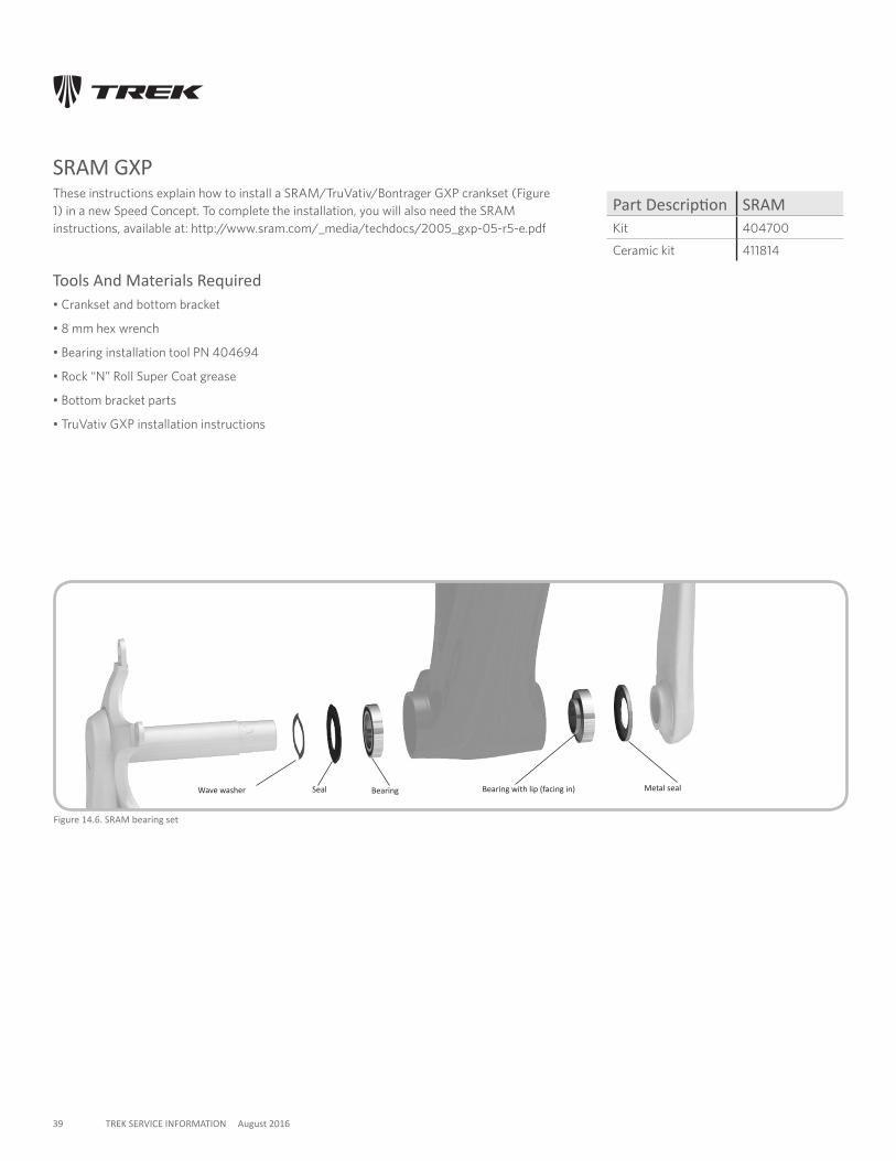
SRAM GXPThese instructions explain how to install a SRAM/TruVativ/Bontrager GXP crankset (Figure 1) in a new Speed Concept. To complete the installation, you will also need the SRAM instructions, available at: http://www.sram.com/_media/techdocs/2005_gxp-05-r5-e.pdf
Tools And Materials Required• Crankset and bottom bracket
• 8 mm hex wrench
• Bearing installation tool PN 404694
• Rock “N” Roll Super Coat grease
• Bottom bracket parts
• TruVativ GXP installation instructions
Figure 14.6. SRAM bearing set
Seal Bearing Metal sealBearing with lip (facing in)Wave washer
Part Description SRAMKit 404700
Ceramic kit 411814
40 TREK SERVICE INFORMATION August 2016
To Install The Bearings
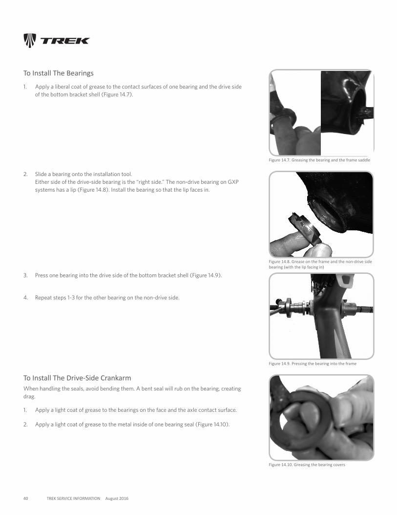
1. Apply a liberal coat of grease to the contact surfaces of one bearing and the drive side of the bottom bracket shell (Figure 14.7).
Figure 14.10. Greasing the bearing covers
Figure 14.9. Pressing the bearing into the frame
Figure 14.7. Greasing the bearing and the frame saddle
Figure 14.8. Grease on the frame and the non-drive side bearing (with the lip facing in)
2. Slide a bearing onto the installation tool. Either side of the drive-side bearing is the “right side.” The non-drive bearing on GXP systems has a lip (Figure 14.8). Install the bearing so that the lip faces in.
3. Press one bearing into the drive side of the bottom bracket shell (Figure 14.9).
4. Repeat steps 1-3 for the other bearing on the non-drive side.
To Install The Drive-Side CrankarmWhen handling the seals, avoid bending them. A bent seal will rub on the bearing, creating drag.
1. Apply a light coat of grease to the bearings on the face and the axle contact surface.
2. Apply a light coat of grease to the metal inside of one bearing seal (Figure 14.10).
41 TREK SERVICE INFORMATION August 2016
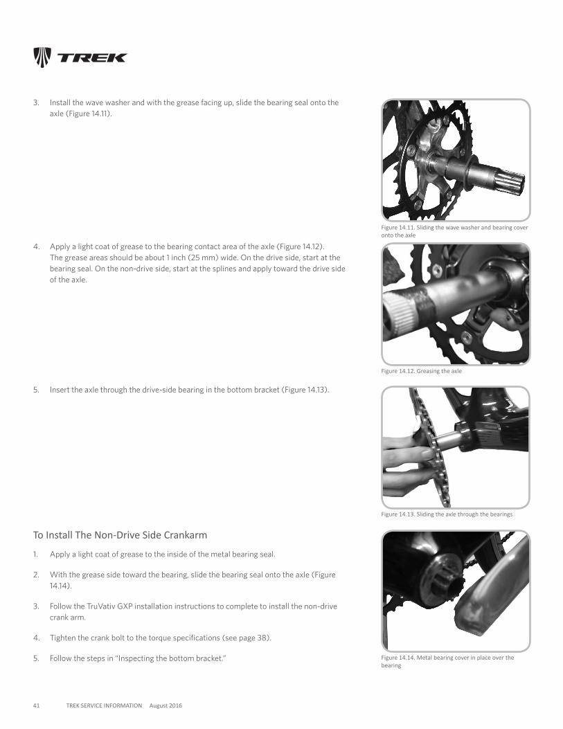
3. Install the wave washer and with the grease facing up, slide the bearing seal onto the axle (Figure 14.11).
Figure 14.13. Sliding the axle through the bearings
Figure 14.14. Metal bearing cover in place over the bearing
Figure 14.12. Greasing the axle
Figure 14.11. Sliding the wave washer and bearing cover onto the axle
5. Insert the axle through the drive-side bearing in the bottom bracket (Figure 14.13).
To Install The Non-Drive Side Crankarm
1. Apply a light coat of grease to the inside of the metal bearing seal.
2. With the grease side toward the bearing, slide the bearing seal onto the axle (Figure 14.14).
3. Follow the TruVativ GXP installation instructions to complete to install the non-drive crank arm.
4. Tighten the crank bolt to the torque specifications (see page 38).
5. Follow the steps in “Inspecting the bottom bracket.”
4. Apply a light coat of grease to the bearing contact area of the axle (Figure 14.12). The grease areas should be about 1 inch (25 mm) wide. On the drive side, start at the bearing seal. On the non-drive side, start at the splines and apply toward the drive side of the axle.
42 TREK SERVICE INFORMATION August 2016
To Remove The Bottom Bracket BearingsThe Speed Concept bottom bracket bearing system is designed to be a slip fit. However, after the first installation some bearings might be tight. If the bearings do not easily come out by hand, you may use the following method to remove them.
1. Slide the crank axle into the bearing so that the bearing is over the non-drive side of the axle, about 1 inch (25 mm) from the non-drive end.
2. Gently rock the axle while you pull the axle out.
Inspecting The Bottom BracketEvery 3 months check the bottom bracket adjustment.
To Check The Bottom Bracket Bearing Adjustment
1. Lift the chain from the chainrings.
2. Rotate the crank so that one of the arms is parallel to the seat tube.
3. Put one hand on the crank arm and one hand on the seat tube, and attempt to move the crank arm laterally toward and away from the seat tube.
4. Spin the cranks.
If the crank feels or sounds loose, or if the motion stops abruptly or you hear a grinding noise coming from the bearings, readjust the bearings or take the bike to your Trek dealer.
43 TREK SERVICE INFORMATION August 2016
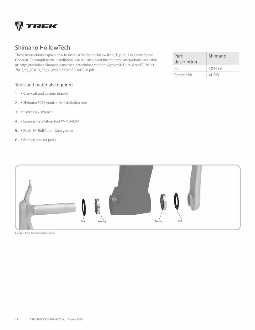
Shimano HollowTechThese instructions explain how to install a Shimano HollowTech (Figure 1) in a new Speed Concept. To complete the installation, you will also need the Shimano instructions, available at: http://techdocs.Shimano.com/media/techdocs/content/cycle/SI/Dura-Ace/FC-7800-7803/SI_1F30H_En_v1_m56577569830605111.pdf.
Tools and materials required
1. • Crankset and bottom bracket
2. • Shimano FC16 crank arm installation tool
3. • 5 mm Hex Wrench
4. • Bearing installation tool PN 404694
5. • Rock “N” Roll Super Coat grease
6. • Bottom bracket parts
Figure 14.15. Shimano bearing set
Seal Bearing SealBearing
Part description
Shimano
Kit 404699
Ceramic kit 411813
44 TREK SERVICE INFORMATION August 2016
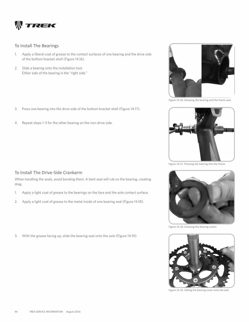
To Install The Bearings
1. Apply a liberal coat of grease to the contact surfaces of one bearing and the drive side of the bottom bracket shell (Figure 14.16).
2. Slide a bearing onto the installation tool. Either side of the bearing is the “right side.”
Figure 14.17. Pressing the bearing into the frame
Figure 14.16. Greasing the bearing and the frame seat
3. Press one bearing into the drive side of the bottom bracket shell (Figure 14.17).
4. Repeat steps 1-3 for the other bearing on the non-drive side.
To Install The Drive-Side CrankarmWhen handling the seals, avoid bending them. A bent seal will rub on the bearing, creating drag.
1. Apply a light coat of grease to the bearings on the face and the axle contact surface.
2. Apply a light coat of grease to the metal inside of one bearing seal (Figure 14.18).
Figure 14.19. Sliding the bearing cover onto the axle
Figure 14.18. Greasing the bearing covers
3. With the grease facing up, slide the bearing seal onto the axle (Figure 14.19).
45 TREK SERVICE INFORMATION August 2016
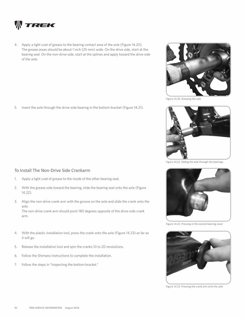
4. Apply a light coat of grease to the bearing contact area of the axle (Figure 14.20). The grease areas should be about 1 inch (25 mm) wide. On the drive side, start at the bearing seal. On the non-drive side, start at the splines and apply toward the drive side of the axle.
Figure 14.21. Sliding the axle through the bearings
Figure 14.20. Greasing the axle
5. Insert the axle through the drive-side bearing in the bottom bracket (Figure 14.21).
To Install The Non-Drive Side Crankarm
1. Apply a light coat of grease to the inside of the other bearing seal.
2. With the grease side toward the bearing, slide the bearing seal onto the axle (Figure 14.22).
3. Align the non-drive crank arm with the groove on the axle and slide the crank onto the axle. The non-drive crank arm should point 180 degrees opposite of the drive-side crank arm.
4. With the plastic installation tool, press the crank onto the axle (Figure 14.23) as far as it will go.
5. Release the installation tool and spin the cranks 10 to 20 revolutions.
6. Follow the Shimano instructions to complete the installation.
7. Follow the steps in “Inspecting the bottom bracket.”
Figure 14.22. Pressing in the second bearing cover
Figure 14.23. Pressing the crank arm onto the axle
46 TREK SERVICE INFORMATION August 2016
To Remove The Bottom Bracket BearingsThe Speed Concept bottom bracket bearing system is designed to be a slip fit. However, after the first installation some bearings might be tight. If the bearings do not easily come out by hand, you may use the following method to remove them.
1. 1. Slide the crank axle into the bearing so that the bearing is over the non-drive side of the axle, about 1 inch (25 mm) from the non-drive end.
2. 2. Gently rock the axle while you pull the axle out.
Inspecting The Bottom Bracket1. Every 3 months check the bottom bracket adjustment.
To Check The Bottom Bracket Bearing Adjustment
1. Lift the chain from the chainrings.
2. Rotate the crank so that one of the arms is parallel to the seat tube.
3. Put one hand on the crank arm and one hand on the seat tube, and attempt to move the crank arm laterally toward and away from the seat tube.
4. Spin the cranks. If the crank feels or sounds loose, or if the motion stops abruptly or you hear a grinding noise coming from the bearings, readjust the bearings or take the bike to your Trek dealer.
47 TREK SERVICE INFORMATION August 2016
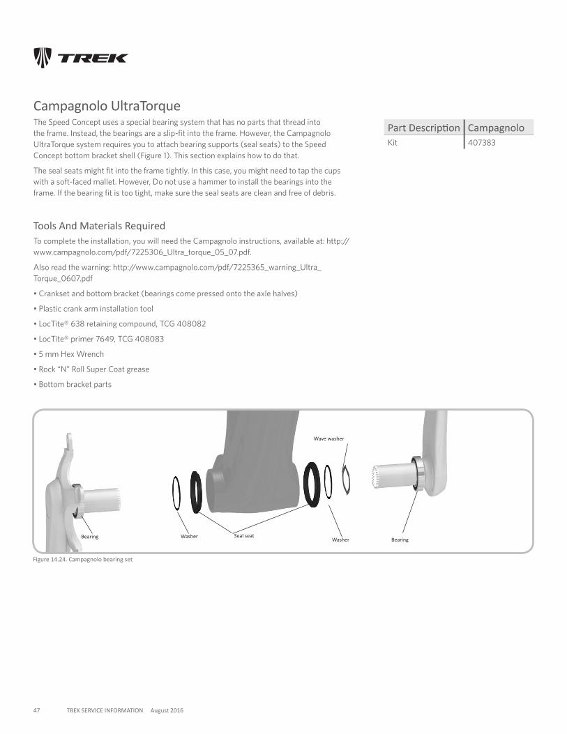
Campagnolo UltraTorqueThe Speed Concept uses a special bearing system that has no parts that thread into the frame. Instead, the bearings are a slip-fit into the frame. However, the Campagnolo UltraTorque system requires you to attach bearing supports (seal seats) to the Speed Concept bottom bracket shell (Figure 1). This section explains how to do that.
The seal seats might fit into the frame tightly. In this case, you might need to tap the cups with a soft-faced mallet. However, Do not use a hammer to install the bearings into the frame. If the bearing fit is too tight, make sure the seal seats are clean and free of debris.
Tools And Materials RequiredTo complete the installation, you will need the Campagnolo instructions, available at: http://www.campagnolo.com/pdf/7225306_Ultra_torque_05_07.pdf.
Also read the warning: http://www.campagnolo.com/pdf/7225365_warning_Ultra_Torque_0607.pdf
• Crankset and bottom bracket (bearings come pressed onto the axle halves)
• Plastic crank arm installation tool
• LocTite® 638 retaining compound, TCG 408082
• LocTite® primer 7649, TCG 408083
• 5 mm Hex Wrench
• Rock “N” Roll Super Coat grease
• Bottom bracket parts
Figure 14.24. Campagnolo bearing set
Bearing Bearing
Wave washer
WasherWasher Seal seat
Part Description CampagnoloKit 407383
48 TREK SERVICE INFORMATION August 2016
To Install The Seal Seats
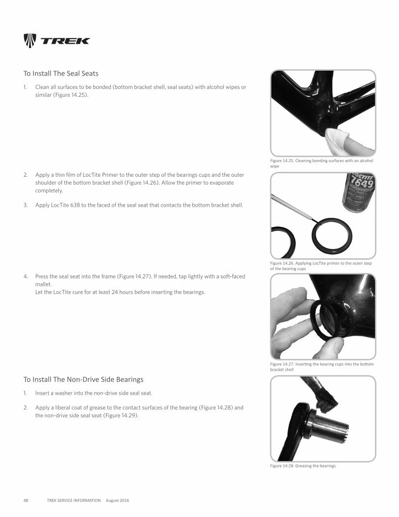
1. Clean all surfaces to be bonded (bottom bracket shell, seal seats) with alcohol wipes or similar (Figure 14.25).
Figure 14.27. Inserting the bearing cups into the bottom bracket shell
Figure 14.28. Greasing the bearings
Figure 14.25. Cleaning bonding surfaces with an alcohol wipe
Figure 14.26. Applying LocTite primer to the outer step of the bearing cups
2. Apply a thin film of LocTite Primer to the outer step of the bearings cups and the outer shoulder of the bottom bracket shell (Figure 14.26). Allow the primer to evaporate completely.
3. Apply LocTite 638 to the faced of the seal seat that contacts the bottom bracket shell.
4. Press the seal seat into the frame (Figure 14.27). If needed, tap lightly with a soft-faced mallet. Let the LocTite cure for at least 24 hours before inserting the bearings.
To Install The Non-Drive Side Bearings
1. Insert a washer into the non-drive side seal seat.
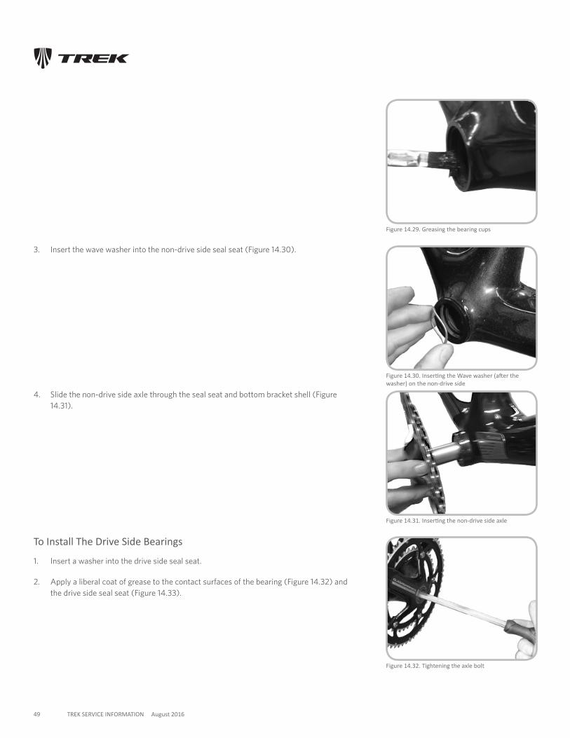
2. Apply a liberal coat of grease to the contact surfaces of the bearing (Figure 14.28) and the non-drive side seal seat (Figure 14.29).
49 TREK SERVICE INFORMATION August 2016
Figure 14.32. Tightening the axle bolt
Figure 14.31. Inserting the non-drive side axle
3. Insert the wave washer into the non-drive side seal seat (Figure 14.30).
Figure 14.29. Greasing the bearing cups
Figure 14.30. Inserting the Wave washer (after the washer) on the non-drive side
4. Slide the non-drive side axle through the seal seat and bottom bracket shell (Figure 14.31).
To Install The Drive Side Bearings
1. Insert a washer into the drive side seal seat.
2. Apply a liberal coat of grease to the contact surfaces of the bearing (Figure 14.32) and the drive side seal seat (Figure 14.33).
50 TREK SERVICE INFORMATION August 2016
3. Slide the drive side axle through the seal seat and bottom bracket shell (Figure 9).
4. Line up the splines of the bottom bracket axle and press the axle together. If necessary, tap the ends together with the heel of your palms.
5. Insert the crank bolt from the drive side (Figure 10) and tighten to the torque specifications (see page 38).
6. Follow the steps in “Inspecting the bottom bracket.”
To Remove The Bottom Bracket BearingsWith the Campagnolo system, each of the two bearings are pressed onto one of the halves of the bottom bracket axle. To remove the bearings, follow the Campagnolo service instructions.
Inspecting The Bottom BracketEvery 3 months check the bottom bracket adjustment.
To Check The Bottom Bracket Bearing Adjustment
1. Lift the chain from the chainrings.
2. Rotate the crank so that one of the arms is parallel to the seat tube.
3. Put one hand on the crank arm and one hand on the seat tube, and attempt to move the crank arm laterally toward and away from the seat tube.
4. Spin the cranks.
If the crank feels or sounds loose, or if the motion stops abruptly or you hear a grinding
noise coming from the bearings, readjust the bearings or take the bike to your Trek
dealer.
51 TREK SERVICE INFORMATION August 2016
FSA MegaExo ALThese instructions and parts are for the aluminum FSA cranks only. The current “B” kit will not work for FSA carbon cranks.
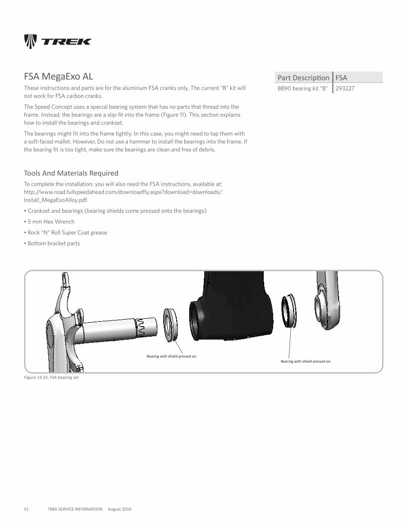
The Speed Concept uses a special bearing system that has no parts that thread into the frame. Instead, the bearings are a slip-fit into the frame (Figure 11). This section explains how to install the bearings and crankset.
The bearings might fit into the frame tightly. In this case, you might need to tap them with a soft-faced mallet. However, Do not use a hammer to install the bearings into the frame. If the bearing fit is too tight, make sure the bearings are clean and free of debris.
Tools And Materials RequiredTo complete the installation, you will also need the FSA instructions, available at: http://www.road.fullspeedahead.com/downloadfly.aspx?download=downloads/ Install_MegaExoAlloy.pdf.
• Crankset and bearings (bearing shields come pressed onto the bearings)
• 5 mm Hex Wrench
• Rock “N” Roll Super Coat grease
• Bottom bracket parts
Figure 14.33. FSA bearing set
Bearing with shield pressed on
Part Description FSABB90 bearing kit “B” 293227
Bearing with shield pressed on
52 TREK SERVICE INFORMATION August 2016
To Install The Bearings
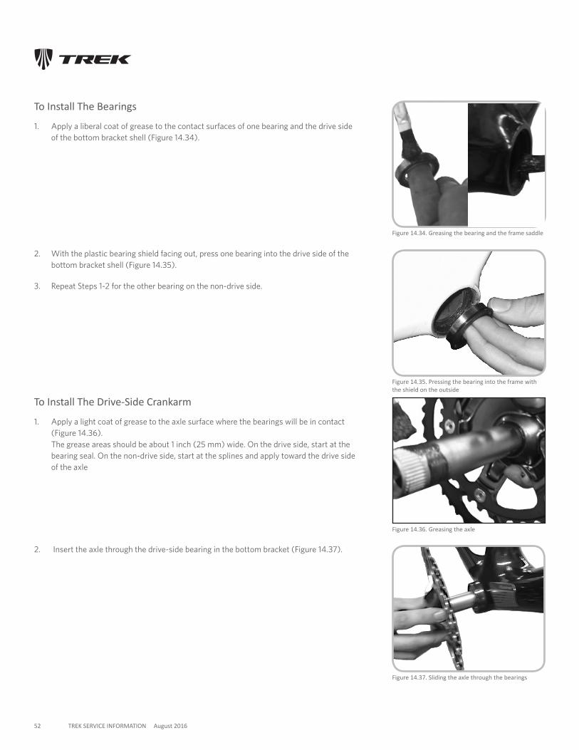
1. Apply a liberal coat of grease to the contact surfaces of one bearing and the drive side of the bottom bracket shell (Figure 14.34).
Figure 14.36. Greasing the axle
Figure 14.35. Pressing the bearing into the frame with the shield on the outside
Figure 14.34. Greasing the bearing and the frame saddle
Figure 14.37. Sliding the axle through the bearings
2. With the plastic bearing shield facing out, press one bearing into the drive side of the bottom bracket shell (Figure 14.35).
3. Repeat Steps 1-2 for the other bearing on the non-drive side.
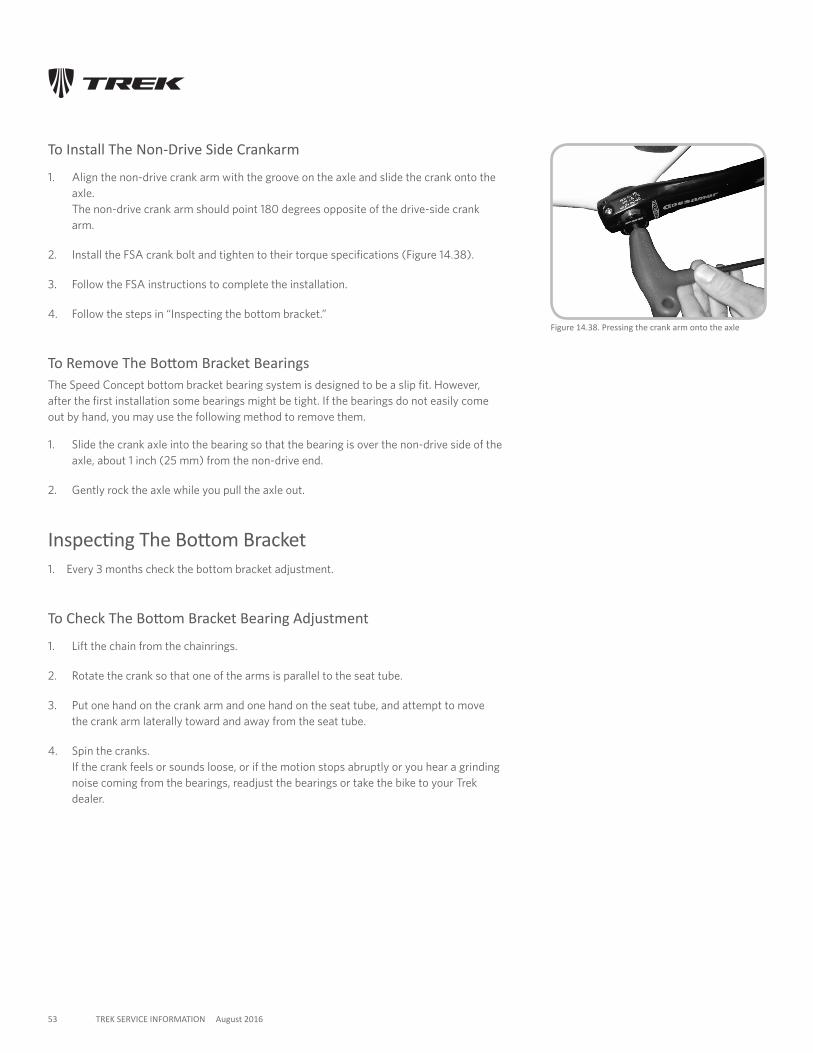
To Install The Drive-Side Crankarm
1. Apply a light coat of grease to the axle surface where the bearings will be in contact (Figure 14.36). The grease areas should be about 1 inch (25 mm) wide. On the drive side, start at the bearing seal. On the non-drive side, start at the splines and apply toward the drive side of the axle
2. Insert the axle through the drive-side bearing in the bottom bracket (Figure 14.37).
53 TREK SERVICE INFORMATION August 2016
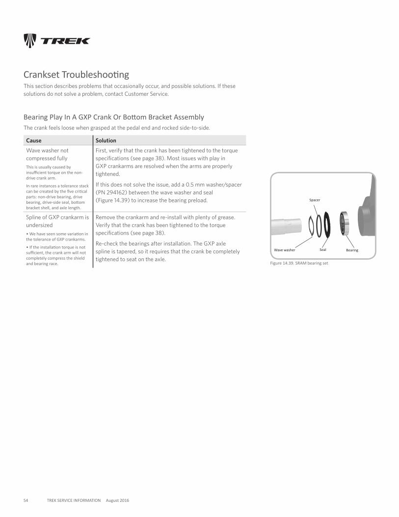
To Install The Non-Drive Side Crankarm
1. Align the non-drive crank arm with the groove on the axle and slide the crank onto the axle. The non-drive crank arm should point 180 degrees opposite of the drive-side crank arm.
2. Install the FSA crank bolt and tighten to their torque specifications (Figure 14.38).
3. Follow the FSA instructions to complete the installation.
4. Follow the steps in “Inspecting the bottom bracket.”
To Remove The Bottom Bracket BearingsThe Speed Concept bottom bracket bearing system is designed to be a slip fit. However, after the first installation some bearings might be tight. If the bearings do not easily come out by hand, you may use the following method to remove them.
1. Slide the crank axle into the bearing so that the bearing is over the non-drive side of the axle, about 1 inch (25 mm) from the non-drive end.
2. Gently rock the axle while you pull the axle out.
Inspecting The Bottom Bracket1. Every 3 months check the bottom bracket adjustment.
To Check The Bottom Bracket Bearing Adjustment
1. Lift the chain from the chainrings.
2. Rotate the crank so that one of the arms is parallel to the seat tube.
3. Put one hand on the crank arm and one hand on the seat tube, and attempt to move the crank arm laterally toward and away from the seat tube.
4. Spin the cranks. If the crank feels or sounds loose, or if the motion stops abruptly or you hear a grinding noise coming from the bearings, readjust the bearings or take the bike to your Trek dealer.
Figure 14.38. Pressing the crank arm onto the axle
54 TREK SERVICE INFORMATION August 2016
Crankset TroubleshootingThis section describes problems that occasionally occur, and possible solutions. If these solutions do not solve a problem, contact Customer Service.
Bearing Play In A GXP Crank Or Bottom Bracket AssemblyThe crank feels loose when grasped at the pedal end and rocked side-to-side.
Cause Solution
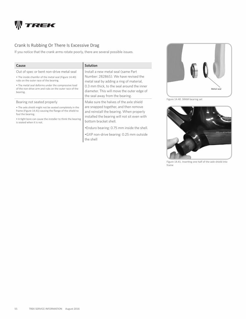
Wave washer not compressed fullyThis is usually caused by insufficient torque on the non-drive crank arm.
In rare instances a tolerance stack can be created by the five critical parts: non-drive bearing, drive bearing, drive-side seal, bottom bracket shell, and axle length.
First, verify that the crank has been tightened to the torque specifications (see page 38). Most issues with play in GXP crankarms are resolved when the arms are properly tightened.
If this does not solve the issue, add a 0.5 mm washer/spacer (PN 294162) between the wave washer and seal (Figure 14.39) to increase the bearing preload.
Spline of GXP crankarm is undersized• We have seen some variation in the tolerance of GXP crankarms.
• If the installation torque is not sufficient, the crank arm will not completely compress the shield and bearing race.
Remove the crankarm and re-install with plenty of grease. Verify that the crank has been tightened to the torque specifications (see page 38).
Re-check the bearings after installation. The GXP axle spline is tapered, so it requires that the crank be completely tightened to seat on the axle.
Figure 14.39. SRAM bearing set
Seal BearingWave washer
Spacer
55 TREK SERVICE INFORMATION August 2016
Crank Is Rubbing Or There Is Excessive DragIf you notice that the crank arms rotate poorly, there are several possible issues.
Cause Solution
Out of spec or bent non-drive metal seal • The inside chamfer of the metal seal (Figure 14.40) rubs on the outer race of the bearing.
• The metal seal deforms under the compressive load of the non-drive arm and rubs on the outer race of the bearing.
Install a new metal seal (same Part Number: 282865). We have revised the metal seal by adding a ring of material, 0.3 mm thick, to the seal around the inner diameter. This will move the outer edge of the seal away from the bearing.
Bearing not seated properly• The axle shield might not be seated completely in the frame (Figure 14.41) causing the flange of the shield to foul the bearing.
• A tight bore can cause the installer to think the bearing is seated when it is not.
Make sure the halves of the axle shield are snapped together, and then remove and reinstall the bearing. When properly installed the bearing will not sit even with bottom bracket shell.
•Enduro bearing: 0.75 mm inside the shell.
•GXP non-drive bearing: 0.25 mm outside the shell
Figure 14.40. SRAM bearing set
Metal seal
Figure 14.41. Inserting one half of the axle shield into frame