
2014-2015 Electrostatics
34
UNIVERSIT ´ E DE PARIS SUD U.F.R SCIENTIFIQUE D’ORSAY Licence et Magist` ere de Physique 2014-2015 Classical Electromagnetism ——- Lecture Notes
description
cours
Transcript of 2014-2015 Electrostatics
UNIVERSITE DE PARIS SUD
U.F.R SCIENTIFIQUE D’ORSAY
Licence et Magistere de Physique
2014-2015
Classical Electromagnetism
——-
Lecture Notes
26 CHAPTER 1. Introduction and overview - Electromagnetism
1.8 Additional reading
The following article 16, describes one application of radiation pressure.
16. Dachwald et al., Int. AAAF Symposium on Space Propulsion, 2002.
PERFORM
ANCE
REQUIR
EM
ENTSFOR
NEAR-T
ERM
INTERPLANETARY
SOLAR
SAIL
CRAFT
MIS
SIO
NS
BerndDachwald
1,W
olfgangSeboldt1
andBerndHausler2
1German
AerospaceCenter(D
LR),
Colog
ne
Institute
ofSpaceSen
sorTechnolog
yan
dPlanetaryExploration
Phon
e:+49
-220
3-60
1{300
1|302
8}Fax
:+49
-220
3-60
146
55E-M
ail:{b
ernd.dachwald|wolfgan
g.seboldt}@dlr.de
2Universitatder
Bundesweh
rMunchen
,Neu
biberg
InstitutfurRau
mfahrttechnik
Phon
e:+49
-89-60
0421
38Fax
:+49
-89-60
0421
38E-M
ail:
bernd.haeusler@unibw-m
uen
chen
.de
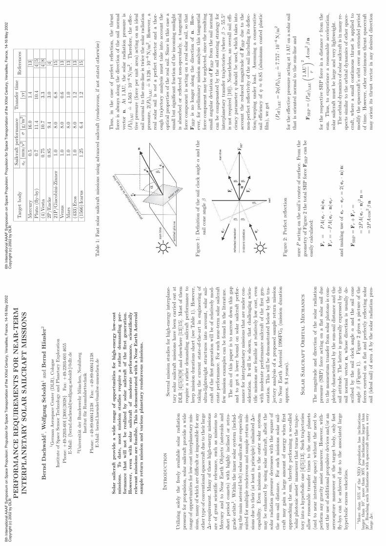
Solarsailcraft
provide
awide
range
ofopportu
nitiesforhigh-energy
low-cost
missions.
To
date,
most
mission
stu
dies
require
arath
er
demanding
per-
formance
that
willnot
be
realized
by
solar
sailcraft
ofth
efirst
generation.
However,
even
with
solar
sailcraft
of
moderate
performance,
scientifically
relevantmissionsarefeasible.This
isdemonstratedwithaNearEarth
Asteroid
sample
retu
rn
mission
and
variousplaneta
ryrendezvousmissions.
Introduction
Utilizing
solely
the
freely
available
solarradiation
pressure
forpropulsion,solarsailcraftprovideawide
range
ofop
portunitiesforlow-costinterplanetarymis-
sion
s,man
yof
whicharediffi
cultor
impossibleforan
yother
typeof
convention
alspacecraftdueto
theirlarge
∆v-requirem
ent.
Man
yof
thosehigh-energy
mission
sareof
greatscientificrelevance,such
asmission
sto
Mercury
and
toNearEarth
Objects(asteroidsan
dshortperiod
comets)
with
highly
inclined
orretro-
grad
eorbits1.W
ithin
theinner
solarsystem
(includ-
ingthemainasteroid
belt)solarsailcraftareespecially
suited
formultiplerendezvousan
dsamplereturn
mis-
sion
sdueto
their(atleastin
principle)unlimited
∆v-
capab
ility.
Evenmission
sto
theou
tersolarsystem
may
beenhan
cedbyusingsolarsailcraft,
albeitthe
solarradiation
pressure
decreases
withthesquareof
thesun–saildistance.
For
such
mission
ssolarsail-
craftmay
gain
alargeam
ountof
energy
when
first
approachingthesun,therebyperform
ingaso-called
’solar
photon
icassist’man
euverthat
turnsthetrajec-
tory
into
ahyperbolic
one[4][5][13].Such
trajectories
allow
reason
able
tran
sfer
times
totheou
terplanets
(andto
nearinterstellar
space)
withou
ttheneedto
perform
anygravityassist
man
euver.
How
ever,with-
outtheuse
ofad
ditional
propulsivedevices
and/oran
aerocapture
man
euverat
thetarget
body,
only
fast
fly-byscan
beachieved
dueto
theassociated
large
hyperbolic
excess
velocities.
1More
than
55%
oftheNEO
population
hasinclinations
larger
than
10◦,more
than
30%
hasinclinationslarger
than
20◦.Reach
ingsuch
inclinationswithspacecraft
requires
avery
large∆v.
Several
mission
studiesforhigh-energy
interplane-
tary
solarsailcraftmission
shavebeencarriedou
tat
DLR
[4][5][8][9]
andelsewhere[13][15].Mostof
them
requirearather
dem
andingsailcraftperform
ance
tokeep
mission
duration
sshort(see
Tab
le1).How
ever,
takingthecurrentstate-of-the-artin
engineeringof
ultra-lightw
eigh
tstructuresinto
account,
solarsail-
craftof
thefirstgenerationwillbeof
relativelymod-
erateperform
ance.For
such
near-term
solarsailcraft
few
mission
exam
plescanbefoundin
theliterature.
Theaim
ofthis
pap
eris
tonarrow
dow
nthis
gap
and
togetalower
bou
nd
onsolarsailcraftperfor-
man
ceforinterplanetarymission
sthat
areunder
con-
sideration.It
willbeshow
n,that
challengingscien-
tificmission
sarefeasible
atrelatively
low
cost,even
withmoderateperform
ance
sailcraftof
thefirstgen-
eration.This
willbedem
onstratedbelow
bythetra-
jectoryan
alysisof
aproposed
sample
return
mission
toNearEarth
Asteroid
1996FG
3(m
ission
duration
approx.9.4years).
SolarSailcraftOrbitalMechanics
Themagnitudean
ddirection
ofthesolarradiation
pressure
(SRP)forceactingon
aflat
solarsail
due
tothemom
entum
tran
sfer
from
solarphoton
siscom-
pletely
characterizedbythesun-saildistance
andthe
sailattitude.
Thelatter
isgenerally
expressed
bythe
sail
normal
vector
n,whosedirection
isusually
de-
scribed
by
thesail
clock
angleα
and
thesail
cone
angleβ
(Figure
1).
Figure
2givesapicture
ofthe
forces
exertedon
aflat
andperfectly
reflectingsolar
sail(idealsail)of
area
Abythesolarradiation
pres-
6th
Inte
rnational A
AA
F S
ym
posiu
m o
n S
pace P
ropuls
ion:
Pro
puls
ion f
or
Space T
ransport
ation o
f th
e X
XIs
t C
entu
ry,
Vers
aill
es,
Fra
nce,
14-1
6 M
ay 2
002
Copyright
(c)
2002 b
y D
LR
Sailcraft
perform
ance
Transfer
time
Target
body
ac[m
m/s2]
σ[g/m
2]
[yr]
References
Mercury
0.5
16.0
1.4
[13]
Pluto
(fly-by)
0.7
11.4
10.4
[4][5]
(4)Vesta
0.75
10.7
3.3
[4][8]
2P/Encke
0.85
9.4
3.0
[4]
21P/Giacobini-Zinner
1.0
8.0
6.8
[15]
Venus
1.0
8.0
0.6
[13]
Mars
1.0
8.0
1.0
[13]
(433)Eros
1.0
8.0
1.2
[13]
(1566)Icarus
1.25
6.4
1.2
[15]
Tab
le1:
Fastsolarsailcraft
missionsusingadvancedsailcraft
(rendezvous,
ifnotstatedotherwise)
Figure
1:Definitionofthesailclock
angle
αandthe
sailconean
gle
β
Figure
2:Perfect
reflection
sure
Pactingon
thesail’scenterofsurface.From
the
geom
etry
ofFigure
2thetotalSRPforceFSRPcanbe
easily
calculated:
Fr=
PA(er·n
)er
Fr′=−PA(er·n
)er′
andmak
inguse
ofer−
er′=
2(er·n
)n:
FSRP=
Fr+Fr′=
=2P
A(er·n
)2n=
=2P
Acos2βn
Thus,
inthe
case
ofperfect
reflection,the
thrust
forceis
alwaysalongthedirectionofthesailnormal
vector
n.
At1AU,thesolarradiation
pressure
is(P
0) 1
AU
. =4.563·1
0−6N/m
2.
Therefore,theeff
ec-
tive
pressure
(forceper
unit
area)actingonanideal
sailnorm
alto
thesun-lineistw
icethesolarradiation
pressure,2(P
0) 1
AU
. =9.126·1
0−6N/m
2.How
ever,a
realsolarsail
isnotaperfect
reflectorand
athor-
oughtrajectory
analysismust
takeinto
accountthe
opticalproperties
oftherealsail.Since
inthiscase
asm
allbutsignificantfractionoftheincomingsunlight
isabsorbed
orreflected
non-specularly,
atangential
forcecomponentis
actingonarealsolarsail,so
that
FSRP
isnolonger
alongthedirection
ofn.
How
-ever,forpreliminary
missionanalysisthis
tangential
forcecomponentmay
beneglected,since
theresulting
smallangulardeviationofFSRPfrom
thesailnormal
canbecompensatedbythesailsteeringstrategyfor
interplanetary
transfer
trajectories
(whereβ>
55.5◦
isnotrequired
[10]).Nonetheless,
anoverallsaileffi
-ciency
parameter
ηshould
beused,whichtakesinto
accountthereduced
magnitudeofFSRP
dueto
the
non-perfect
reflectivityofthesailincludingitsdeflec-
tion/w
arpingunder
load.
Assumingaconservative
saileffi
ciency
ofη≈
0.85(aluminum
coatedplastic
film
),weget
(Peff) 1
AU=
2η(P
0) 1
AU
. =7.757·10−6N/m
2
fortheeff
ective
pressure
actingat1AU
onasolarsail
thatis
orientednorm
alto
thesun-lineand
FSRP=
(Peff) 1
AU
(
1AU
r
)
2
Acos2βn
fortherespective
SRP
forcein
adistance
rfrom
the
sun.
Thus,
toexperience
areasonable
acceleration,
solarsailcraft
must
belargeandvery
lightw
eight.
Theorbitaldynamicsofsolarsailcraftisin
manyre-
spects
similarto
theorbitaldynamicsofother
space-
craft,whereasm
allcontinuousthrust
isapplied
tomodifythespacecraft’sorbitover
anextended
period
oftime.
How
ever,other
continuousthrust
spacecraft
may
orientitsthrust
vectorin
anydesired
direction
6th
Inte
rnational A
AA
F S
ym
posiu
m o
n S
pace P
ropuls
ion:
Pro
puls
ion f
or
Space T
ransport
ation o
f th
e X
XIs
t C
entu
ry,
Vers
aill
es,
Fra
nce,
14-1
6 M
ay 2
002
Copyright
(c)
2002 b
y D
LR

andvary
itsthrust
levelwithin
awiderange,whereas
thethrust
vector
ofsolarsailcraftisconstrained
tolie
onthesurfaceof
a’bubble’directedaw
ayfrom
the
sun(see
Figure
3).Nevertheless,
bycontrollingthe
sailorientation
relative
tothesun,solarsailcraftcan
gain
orbital
angu
larmom
entum
(ifFSRP·e
t>
0)an
dspiral
outw
ards–aw
ayfrom
thesun–or
lose
orbital
angu
larmom
entum
(ifFSRP·e
t<
0)an
dspiral
in-
wards–towardsthesun.
Figure
3:Spirallinginwardsan
dou
twards
SolarSailcraftPerformance
Parameters
Beforetalkingab
outperform
ance
ofnear-term
solar
sailcraft,
themostcommon
perform
ance
definitions
shou
ldbegiven.
Theperform
ance
ofsolarsailcraft
may
beexpressed
bythefollow
ingparam
eters:
•thesailassembly
load
ing
σ s=
ms
A
isdefined
asthemassof
thesailassembly
(the
sailfilm
andtherequired
structure
forstoring,
deployingan
dtension
ingthesail,index
’s’)
per
unit
area.Thus,
thesailassembly
load
ingis
the
keyparameter
fortheperform
ance
ofasolarsail
andtheeffi
ciency
ofitsstructuraldesign.
•thesailcraftload
ing
σ=
m A=
ms+m
p
A=
σ s+
mp
A
isdefined
accordingly
asthespecificmassof
sail-
craftincludingthepayload
(index
’p’).It
shou
ldbenoted,that
theterm
payload
stan
dsforthe
totalsailcraftexceptthesolarsailassembly
(i.e.
exceptthepropulsionsystem
).
•thecharacteristicacceleration
acisdefined
asthe
max
imum
acceleration
at1AU
solardistance.It
canbecalculatedvia
(Peff) 1
AUA
=mac=
σAac=
=(σ
s+
mp
A)A
ac
⇒ac=
(Peff) 1
AU
σ s+
mp
A
Using
thecharacteristic
acceleration
,theSRP
forceactingon
thesailcanbewritten
as
FSRP=
mac
(
1AU
r
)
2
cos2βn
•the
ligh
tnessnumber
λ,which
isindep
endent
from
solardistance,is
defined
astheratioof
the
SRPacceleration
experiencedbyasolarsailnor-
mal
tothesun
linean
dthesolargravitational
acceleration
(5.93mm/s2
at1AU)
λ=
ac
5.93
mm/s2
Usingtheligh
tnessnumber,theSRPforceacting
onthesailcanbewritten
as
FSRP=
λµm r2
cos2βn
whereµ=
GM
sun.
DLR
Ground-based
Demonstrationof
SolarSail
Technology
InDecem
ber
1999
agrou
nd-based
dem
onstration
ofsolarsailcrafttechnologywas
perform
edat
theGer-
man
AerospaceCenter(D
LR)at
Cologne,
wherea
20m×
20m
solarsailwas
successfullydeployedin
asimulated
zero-g
environ
mentan
dam
bientenviron
-mentalconditions(F
igure
4)[6][14].
Figure
4:Fullydeployed20
m×20
msolarsailat
DLR
Thesquaresolarsailconsisted
offourCFRP
(Car-
bon
Fiber
Reinforced
Plastics)
boom
swithaspecific
massof
101g/m
andof
fourtriangu
larsailsegm
ents
mad
eof
aluminum-coated(0.1µm)plastic
film
swith
6th
Inte
rnational A
AA
F S
ym
posiu
m o
n S
pace P
ropuls
ion:
Pro
puls
ion f
or
Space T
ransport
ation o
f th
e X
XIs
t C
entu
ry,
Vers
aill
es,
Fra
nce,
14-1
6 M
ay 2
002
Copyright
(c)
2002 b
y D
LR
athicknessbetween4and12µm.
Theboomscon-
sisted
oftw
oCFRP
shells
thatwerebonded
atthe
edgesto
form
atubularshape,
sothatthey
canbe
pressed
flat
androlled
up(F
igure
5).
Figure
5:DLR
deployable
CFRP
boom
Theboom
swererolled
up
ina60cm
×60cm
×65
cm-sized
deployment
module,
from
where
they
unfolded
automatically.
After
deploymentthey
re-
turned
totheirtubularshapewithhighbendingand
bucklingstrength.
Subsequently,
thefoursail
seg-
ments
weredeployedbyropes.Toassessthehand-
lingbehav
iorof
differentsailmaterials,thesailseg-
ments
weremad
eof
threedifferentaluminum-coated
plastic
film
s,12
µm
polyethyleneterephtalate
(PET,
Mylarr
),7.5µm
polyim
ide(P
I,Kaptonr)and4µm
polyethylenenap
hthalate
(PEN).
Allsegments
were
reinforced
alon
gthethreeedges
ofthetriangle
toprevent
rips.
The
specific
mass
ofthe
sail
film
was
18.9g/m
2fortheMylarr
-segment,12.4g/m
2for
theKap
tonr-segmentand
10.5g/m
2forthePEN-
segm
ent.
Thedeploymentmodule
andthecross
sec-
tion
oftheboom
sforthisground-baseddem
onstration
weredim
ension
edfora40m×
40m
solarsail,which
was
toolargeforan
in-doordem
onstration.Forthe
structuralsizingof
theboomstw
oloadcaseswerecon-
sidered,bending–dueto
theSRPforce–andbuckling
–dueto
sail
deploymentand
sail
tensioningforces.
Accordingto
FEM
(FiniteElementMethod)calcula-
tion
s,similar
boom
scould
beusedalsoforlarger
sails
[7].
DLR
MissionProposalforENEAS
NearEarth
Asteroids(N
EAs)
are
apromisingcate-
gory
oftarget
bodiesforafirstsolarsailcraftmission,
since
they
canbeaccessed
relatively
easily
andsince
they
areof
greatscientificinterest.Therefore,in
Au-
gust
2000,adedicated
missionfortheexplorationof
NEAswithsolarsailcraft
(ENEAS)wasproposedby
DLR
incoop
erationwiththeWestfalischeW
ilhelms-
Universitatat
Munster
(Germany)asa
candidate
within
theGerman
small
satelliteprogram
forex-
traterrestric
sciences[3][14].
Based
on
thesuccess-
fuldeploymentexperim
entdescribed
above,
ENEAS
(Figure
6)wasintended
tofeature
adeployable50m×
50m
solarsailthatwould
becapable
totransporta
micro-satellitewithamass
of65.5kgto
aNEA
within
less
thanfive
years.Table
2summarizestheENEAS
parameters.
Figure
6:DLR
ENEASsolarsailcraft
withdeployed
controlmast
(artist’sview)
Sailarea
A(50m)2
Sailassem
bly
loading
σ s29.2g/m
2
Sailassem
bly
mass
ms
73kg
Payloadmass
mp
65.5kg
Totalsailcraft
mass
m138.5kg
Sailcraft
loading
σ55.4g/m
2
Lightnessnumber
λ1/42.4
Characteristicacceleration
ac
0.14mm/s2
CharacteristicSRP
force
FSRP,c
19.5mN
Table
2:ParametersfortheENEASsolarsailcraft
Forpropulsionless
attitudecontrol,
thesolarsail
and
the
micro-satellite
would
be
separated
by
acommerciallyavailable
10m
collapsible
controlmast,
whichis
housedinsidethedeploymentmodule
inits
stow
edconfiguration.Thiscontrolmast
isattached
tothedeploymentmodule
via
atw
odegreeoffreedom
actuatorgim
bal,whichallow
sto
rotate
themast
in-
cludingtheattached
micro-satellitewith
respectto
thesail
(Figure
6).
Thus,
by
rotating
thecontrol
mast,thecenterofmass
(CM)can
beoffsetfrom
thecenterofpressure
(CP).
Theresultingexternal
torquemay
beusedto
rotate
thesailaboutanyCM-
intersectingaxis
parallel
tothesailplane(this
atti-
tudecontrolconceptwasoriginallyproposedby[1]).
1996FG
3waschosen
asthetarget
body
forthe
ENEASmission,since
1996FG
3hasorbitalelem
ents
nottoodifferentfrom
thatofEarthandsince
itisan
object
ofexceptionalscientificinterest.Observations
indicatethat1996FG
3is
abinary
asteroid,consist-
ingofacentralbodywitharotationperiodofab
out
3.60hours
and
asatellitewith
an
orbitalperiod
of
about16.15hours.Thedetermined
averagebulk
den-
sity
is1.4±
0.3g/cm
3whichis
highly
suggestive
of
a’rubble
pile’
structure
[12].
ENEASis
intended
to
6th
Inte
rnational A
AA
F S
ym
posiu
m o
n S
pace P
ropuls
ion:
Pro
puls
ion f
or
Space T
ransport
ation o
f th
e X
XIs
t C
entu
ry,
Vers
aill
es,
Fra
nce,
14-1
6 M
ay 2
002
Copyright
(c)
2002 b
y D
LR

determinethephysicalproperties
andtheevolution
ofthe1996FG
3system
.Trajectoryop
timizationusingthecalculusof
vari-
ationsrevealed,that
theENEASsailcraftcanreach
1996FG
3in
4.5years(1640days),ifit
isinserted
di-
rectly
into
aninterplanetarytrajectorywithahyper-
bolic
excess
energy
ofC3=
4km
2/s2.How
ever,more
recentlyperform
edtrajectoryop
timization,based
onartificial
neuralnetworksan
devolution
aryalgorithms
producedabettertrajectoryforthesamelaunch
date,
whichiscloser
tothe(unknow
n)glob
alop
timum
(Fig-
ure
7)[2].
Figure
7:1996FG
3rendezvoustrajectoryfor
ac=
0.14
mm/s
2
Theflighttimecould
bereducedby45
days(3%),
reducingat
thesametimetheC3requirem
entfrom
4km
2/s2
to0km
2/s2,thuspermittingareductionof
launch
cost.Theaccuracy
ofthetrajectorygenerated
bytheartificial
neuralnetworkis∆r<
11000km
for
therelative
distance
tothetarget
bodyat
rendezvous
and∆v<
43m/sfortherelative
velocity
(evenwith-
outperform
ingalocalfinetuningof
thetrajectory)
[2].
Near-Term
SolarSailcraft
Performance
Look
ingat
theequationforthecharacteristic
acceler-
ationof
solarsailcraftwithasquaresail,
ac=
(Peff) 1
AU
σ s+
mp
s2
,
onecanseethat
theperform
ance
dep
endson
three
designparameters,
thesailassembly
load
ingσ s,the
payload
massm
pan
dthesidelengths(orarea
s2)of
thesolarsail,definingathree-dim
ension
alsolarsail
designspace.
Figures8an
d9show
param
etricsec-
tion
sof
this
designspaceforafixed
σ s=
29.2g/m
2
andafixed
s=
50m
respectively
(asfortheENEAS
sailcraft).Ascanbeseen
from
thediagram
inFigure
8,acharacteristic
acceleration
ofupto
0.265mm/s2
canbeachievedwithou
tan
ypayload
.For
asm
aller
acapositivepayload
masscanbeaccommodated,de-
pendingon
thesailsize.Toachieve
acharacteristic
acceleration
beyon
d0.265
mm/s2,thesail
assembly
load
inghas
tobefurther
reduced(F
igure
9).
Figure
8:Thecharacteristic
acceleration
acas
afunctionof
san
dm
pforσ s
=29.2g/m
2
Figure
9:Thecharacteristic
acceleration
acas
afunctionof
σ san
dm
pfors=
50m
Bydifferentcombinationsof
thethreedesignpa-
rametersan
ydesired
characteristic
acceleration
can
beachieved2.
Anincrease
inpayload
masscan,for
exam
ple,beoff
setwithaproportion
alincrease
ofs2
orwitha(not
inverselyproportion
al)decreaseof
σ s.
2It
should
benotedthatm
pandscanbechosenindep
en-
den
tly,
whereasσ s(s)is
afunctionofswith∂σ s/∂s<
0,since
themass
oftheboomsand
thedep
loymen
tmodule
scale
less
thanlinearlywiththesailarea.How
ever,weare
onthesafe
side,
when
weassume∂σ s/∂s=
0to
keepcalculationssimple.
6th
Inte
rnational A
AA
F S
ym
posiu
m o
n S
pace P
ropuls
ion:
Pro
puls
ion f
or
Space T
ransport
ation o
f th
e X
XIs
t C
entu
ry,
Vers
aill
es,
Fra
nce,
14-1
6 M
ay 2
002
Copyright
(c)
2002 b
y D
LR
Thosedesignsensitivitiescanbedetermined
quanti-
tativelyusingsensitivityfunctions,
whichprovidean
indication
oftherelative
importance
ofeach
design
param
eter
foragiven
pointin
thesolarsail
design
space[10].Thesensitivityfunctionforanydesignpa-
rameter
ν∈{σ
s,m
p,s}may
bewritten
as
∆ac
ac
=Λν∆ν ν
with
Λσ s
=−
1
1+
mp/σ ss2
Λm
p=−
1
1+
σ ss2/m
p
Λs=
2
1+
σ ss2/m
p
For
theENEASsailcraft,wehaveΛσ s
=−0.537,
Λm
p=−0.473
and
Λs=
+0.946.
Ascan
beseen,
thesidelengthof
thesailisthemost
criticalparame-
terwithrespectto
theENEASsailcraft
perform
ance.
Thus,
anincrease
inperform
ance
isbestdonebyin-
creasingthesize
ofthesolarsail.
Ifcostscanbedescribed
by(know
norestimated)
functionsof
thethreedesignparameters,then
theop-
timum
(costminim
al)sailcraftdesignforagiven
per-
form
ance
canbedetermined.
ENEASwithSampleReturn
The
ENEAS
sailcraft
wasintended
torendezvous
1996FG
3forremotesensingwithaminim
um
scientific
payload
massof
5kg(C
CD
camera+
IRspectrometer
+magnetom
eter).
Tostudythe1996FG
3system
inmoredetail,itwou
ldbenecessary
toplace
alander
on
thesurfaceof
theasteroid
(e.g.formass
spectrometry
and/oralpha-protonspectrometry).
Someinvestiga-
tion
s(e.g.micro-structure
andisotopeanalysis)
tode-
term
inetheagean
dtheevolutionof1996FG
3could
beachieved
only
by
takingsamplesoftheasteroid
backto
Earth.Dueto
theirunlimited
∆v-capability,
solarsailcraftareespeciallycapable
toperform
such
sample
return
missions.
How
ever,compared
tothe
ENEASrendezvousmission,thepayloadmass
hasto
beincreasedconsiderably.Thekey
questionsforthe
ENEAS-SR
(sam
ple
return)missiondesignare:
Q1:
What
isthemax
imum
acceptable
missiondura-
tion
Tmax?
Q2:
What
istheminim
um
characteristicacceleration
ac,m
into
perform
themissionin
Tmax?
Q3:
What
istheexpectedsailassem
bly
loadingσ s
and
saildim
ension
sfornear-term
solarsailcraft?
Q4:
What
isthemax
imum
payloadmass
toget
ac,m
in
forthespecified
σ sands?
Answ
erto
Q1:Atpresent,
themaxim
um
accept-
able
missiondurationseem
sto
bedetermined
bythe
trip
timerequired
withchem
icalpropulsion,includ-
ing
(eventually
multiple)gravity
assistmaneuvers.
Dueto
therelatively
large∆v-requirem
entofab
out
6−10km/sforamissioncomparable
toENEAS-SR,
butwithchem
icalpropulsion,such
amissionwould
requireeither
anexpensive
launch
vehicle
andheavy
spacecraft,resultingin
ashort
trip
timeofafewyears,
orseveralgravityassists,resultingin
alongtrip
time3.
Since
ourapproach
aim
satlow-cost
missions,only
the
gravityassistoptionseem
sto
beareasonable
conven-
tional
alternative.
Thus,
fortheENEAS-SR
mission
weassumeatotalmissiondurationofmore
thanten
years
asnotacceptable.
Answ
erto
Q2:Trajectory
calculationsshow
,that
anENEAS-SR
missionto
1996FG
3canbeachieved
even
withacharacteristicaccelerationof0.10mm/s
2
in9.40years,includingarendezvoustrajectory
of6.27
years
(2290days,
Figure
10),
340daysofoperations
attheasteroid
andanEarthreturn
trajectory
of2.20
years
(805days,
Figure
11).
Figure
10:1996FG
3rendezvoustrajectory
for
ac=
0.10mm/s2
Answ
erto
Q3:Thediagram
inFigure
12show
sthe
required
sailsize
fordifferentsailassem
bly
loadings
andpayloadmasses,to
obtain
acharacteristicaccel-
eration
of0.10mm/s
2.Basedontheexperienceswith
theground-basedsolarsailtechnologydem
onstration
described
above,
weconsider
amaxim
um
sailsize
of
70m×70m
withasailassem
bly
loadingof29.2g/m
2
(sail
film
+booms+
deploymentmodule)asare-
alistic
–how
ever
stillchallenging–baselineforthe
ENEAS-SR
mission.
Answ
erto
Q4:Thespecified
σ sandsyield
apay-
loadmass
of237kgto
get
acharacteristicacceleration
3similarto
the
Rosetta
mission
tocomet
46P/W
irtanen
,which
willhave
three
interm
ediate
gravity
assistmaneu
vers
(Mars-E
arth-E
arth)andatrip
timeofapproxim
ately
nineyears
6th
Inte
rnational A
AA
F S
ym
posiu
m o
n S
pace P
ropuls
ion:
Pro
puls
ion f
or
Space T
ransport
ation o
f th
e X
XIs
t C
entu
ry,
Vers
aill
es,
Fra
nce,
14-1
6 M
ay 2
002
Copyright
(c)
2002 b
y D
LR
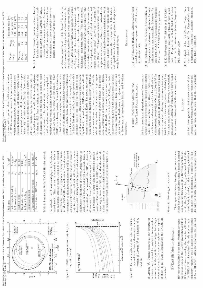
Figure
11:1996FG
3sample
return
trajectoryfor
ac=
0.10
mm/s2
Figure
12:Thesidelengthsof
thesolarsailthat
isrequired
toachieve
acharacteristic
accel-
erationof
0.10mm/s2
asafunctionof
σ san
dm
p
of0.10mm/s2.
Currentresearch
atou
rdepartm
ent
indicates
that
itshou
ldbepossible
torealizesuch
amission
within
thespecified
massbudget,includinga
lander
ofab
out140kgan
dasample
return
capsule
ofab
out40
kg.Tab
le3summarizes
theENEAS-SR
param
eters.
ENEAS-SR
MissionScenario
Since
forsolarsailcraftof
moderateperform
ance
gain-
ingorbital
energy
intheEarth’s
gravitational
fieldis
diffi
cult
andtimeconsuming,
thelauncher
willinsert
theENEAS-SR
solarsailcraftdirectlyinto
aninter-
planetarytrajectorywithahyperbolic
excess
energy
ofC3=
0km
2/s
2.
After
theinjection,thesailan
d
Sailarea
A(70m)2
Sailassembly
load
ing
σ s29.2g/m
2
Sailassembly
mass
ms
143kg
Payload
mass
mp
237kg
Total
sailcraftmass
m380kg
Sailcraft
load
ing
σ77.6g/m
2
Lightnessnumber
λ1/59.3
Characteristic
acceleration
ac
0.10mm/s2
Characteristic
SRP
force
FSRP,c
38.0mN
Tab
le3:
Param
etersfortheENEAS-SRsolarsailcraft
theattitudecontrol
mastaredeployedin
a3-ax
issta-
bilized
mode.
Then
thesail
isoriented
tofollow
apre-calculatedattitudeprofile,lead
ingto
anop
timal
interplanetarytran
sfer
trajectory.
Duringthetran
s-fer,theENEAS-SR
solarsailcraftwillrunalmostau
-tonom
ously,
sothat
grou
ndmon
itoringwillbecarried
outon
aweekly
basison
ly.Attheendof
thetran
sfer
trajectory
thesolarsailcraftwillbemak
ingaren-
dezvouswith1996FG
3within
itsgravitational
sphere
ofinfluence
(Hill-sphere)
ofbetween70
km
radius(at
perihelion)an
d150km
radius(atap
helion).
Evenin
thenear-field
oftheasteroid,theSRP
acceleration
ofbetween0.05mm/s2
(atap
helion)an
d0.21mm/s2
(atperihelion)is
larger
than
theasteroid’s
gravita-
tion
alacceleration
(0.01to
0.00005
mm/s2
inadis-
tance
rangingfrom
5to
50km),
sothat
thesailcraft
isab
leto
hover
onan
artificial
equilibrium
surfacein
thehem
ispherethat
isop
positeto
thesun(F
igure
13).
Figure
13:Hoveringat
theasteroid
Thosequasi-stationaryhoveringpositionsareun-
stab
lebutcanbestab
ilized
usingafeedbackcontrol
loop
tosailattitudealon
e[11].Hoveringneartheas-
teroid,the(likelycomplex)gravitational
fieldof
the
target
bodyis
studied,so
that
acoarse
gravitational
fieldmodel
canbedetermined.Thereafter,thelan-
der
withtheEarth
return
capsule
isseparated
from
6th
Inte
rnational A
AA
F S
ym
posiu
m o
n S
pace P
ropuls
ion:
Pro
puls
ion f
or
Space T
ransport
ation o
f th
e X
XIs
t C
entu
ry,
Vers
aill
es,
Fra
nce,
14-1
6 M
ay 2
002
Copyright
(c)
2002 b
y D
LR
thesolarsailto
gointo
closerorbit
abouttheaster-
oid.W
hilemeasuringtheasteroid’sgravitationalfield
withincreasingaccuracy,theorbitofthelander
iscon-
tinuou
slylowered
untilasafe
landingtrajectory
can
becomputed(som
eorallofthose
extensive
compu-
tation
smay
beperform
edonEarth).
Once
landed,
thesample
isfeddirectlyinto
theEarthreturn
cap-
sule
and
brough
tback
tothehoveringsailcraft.
Inthis
mission
phase,
thesailcraft
iswaiting
edge-on
(sothat
noSRP
forceis
actingon
thesail)atthe
L2Lagrange
pointforthelander
inorder
toassist
therendezvou
s.Thelander
design,thesample
ex-
traction
mechan
ismsandthesubsystem
srequired
torendezvousthewaitingsailcraft
requirefurther
stud-
iesan
darebeyon
dthescopeofthis
paper.
Since
1996FG
3is
abinarysystem
,it
would
beinteresting
tolandan
dextractsamplesfrom
both
bodiesto
in-
vestigatetheorigin
andthecollisionalevolutionofthe
1996FG
3system
.Since
thegravitationalacceleration
isvery
low
neartheasteroid
andtherequired
∆vfor
thelander
less
than
10m/s,
acold
gassystem
witha
propellantmassof
less
than4kgwillsuffice
toper-
form
allop
erations.
After
rendezvouswiththehover-
ingsailcraft,
there-docked
ENEAS-SR
solarsailcraft
returnsthesample
toEarth.Thereturn
trajectory
ismuch
faster
than
thetransfer
trajectory
to1996FG
3
since
norendezvousis
required
atEarth.Thus,
the
sailcraftmay
arrive
with
arelatively
large
hyper-
bolic
excess
velocity
ofabout8.4km/s.
Thegravita-
tion
alacceleration
ofEarthaddsanother
11.2km/s,
sothat
theEarth
reentryvelocity
may
reach
about
√8.4
2+11
.22km/s=
14.0km/s.
Finally,
just
before
thearrivalof
theENEAS-SR
solarsailcraft
atEarth,
thereturn
capsule
isseparatedfrom
thelander
and
injected
into
anEarth
reentry
trajectory,whereit
isdecelerated
by
atmospheric
friction
and
breaking
parachutes.
OtherPromising
Missionsfor
Near-Term
SolarSailcraft
Wehaveinvestigated
theperform
ance
ofnear-term
so-
larsailcraftalso
forrendezvousmissionswithcelestial
bodiesother
than
NearEarthObjects.
Table
4gives
theminim
um
rendezvoustimes
forsolarsailcraftwith
acharacteristic
accelerationof0.10to
0.20mm/s2
for
severaltarget
bodies.
Itshow
sthateven
withnear-
term
solarsailcraftplanetary
rendezvousmissionare
feasiblewithin
theinner
solarsystem
,ifrelatively
long
trip
times
canbetolerated.How
ever,acharacteristic
acceleration
of0.10
mm/s2
seem
sto
bealower
bound
forrendezvousmissionswithin
theinner
solarsystem
.
Summary
Wehaveinvestigated
theminim
um
solarsailcraftper-
form
ance
requirem
ents
forvariousinterplanetary
mis-
sion
s.Wewereab
leto
show
,thatthecharacteristic
Transfer
time[yr]
Target
∆v m
inforac[m
m/s2]
body
[km/s]
0.10
0.15
0.20
Mercury
20.1
8.3
5.9
4.2
Venus
6.8
4.6
2.9
2.0
Mars
6.2
9.2
7.5
5.1
Table
4:Minim
um
transfer
times
totheinner
planets
forsolarsailcraft
withacharacteristicaccel-
erationof0.10,0.15and0.20mm/s2
(∆v m
in
denotestheminim
um
impulsive∆v-values
forellipticalnon-coplanarHohmann-likeor-
bit
transferswithzero
hyperbolicexcess
ve-
locities
atboth
endsofthetrajectory)
accelerationmust
beatleast
0.10mm/s2
inorder
toavoid
unacceptable
longmission
durationseven
for
relatively
easily
accessible
inner
solarsystem
bodies.
A70m×
70m
solarsailwithasailassem
bly
load
ing
of29.2g/m
2(sailfilm
+booms+
deploymentmod-
ule)wasconsidered
tobearealistic
–how
ever
still
challenging–near-term
baseline.
Withthissolarsail,
acharacteristicthrust
of38mN
canbeachieved.The
characteristicacceleration–definingthemissiondu-
ration–dep
endsontheactualpayloadmass
mpand
ranges
from
0.265mm/s2
(mp=
0kg)to
0.10mm/s2
(mp=
237kg).
Wehavealsodem
onstrated,thata
sample
return
missionto
aNearEarthAsteroid
with
such
asolarsailisfeasiblewithin
amissionduration
of
approx.9.4
years.In
additionto
thescientificvalue
ofsuch
amission,thedem
onstration
ofthetechni-
calcapabilitiesofsolarsailpropulsionin
deepspace
would
beacentralobjective.
References
[1]F.AngrilliandS.Bortolami.Attitudeandorbital
modellingofsolar-sailspacecraft.ESA
Journal,
14:431–446,1990.
[2]B.Dachwald
andW
.Seb
oldt.
Optimization
of
interplanetary
rendezvoustrajectories
forsolar
sailcraft
usinganeurocontroller.Monterey,
Au-
gust
2002.AIA
A/AASAstrodynamicsSpecialist
Conference.AIA
A-2002-4989,in
preparation.
[3]E.K
.Jessberger
andW
.Seb
oldtet
al.ENEAS–
exploration
ofnear-earth
asteroidswith
asail-
craft.
Proposalfora
Small
Satellite
Mission
within
theExtraterrestric
SciencesProgram
of
DLR,August
2000.
[4]M.Leipold.
SolarSail
Mission
Design.
Doc-
toralthesis,Lehrstuhlfur
Flugmechanik
und
Flugregelung;TechnischeUniversitatMunchen,
1999.DLR-FB-2000-22.
6th
Inte
rnational A
AA
F S
ym
posiu
m o
n S
pace P
ropuls
ion:
Pro
puls
ion f
or
Space T
ransport
ation o
f th
e X
XIs
t C
entu
ry,
Vers
aill
es,
Fra
nce,
14-1
6 M
ay 2
002
Copyright
(c)
2002 b
y D
LR
[5]M.Leipold.Tothesunan
dpluto
withsolarsails
andmicro-sciencecraft.
ActaAstronautica,45(4-
9):549–555,1999.
[6]M.Leipold,M.Eiden,C.E
.Garner,L.Her-
beck,D.Kassing,
T.Niederstad
t,T.Kruger,
G.Pagel,M.Rezazad
,H.Rozem
eijer,
W.Se-
boldt,C.Schop
pinger,C.Sickinger,an
dW
.Un-
kenbold.Solar
sailtechnologydevelop
mentan
ddem
onstration
.Lau
rel,
2000.4thIA
AInterna-
tion
alCon
ference
onLow
-CostPlanetary
Mis-
sion
s.IA
A-L-0707.
[7]M.Leipold,C.E
.Garner,R.Freelan
d,A.Herr-
man
n,
M.
Noca,
G.
Pagel,
W.
Seb
oldt,
G.Spragu
e,an
dW
.Unckenbold.
ODISSEE
–aproposal
fordem
onstration
ofasolarsail
inearthorbit.ActaAstronautica,45(4-9):557–566,
1999.
[8]M.Leipold,E.Pfeiffer,P.Groepper,M.Eiden,
W.Seb
oldt,L.Herbeck,an
dW
.Unkenbold.So-
larsail
technology
forad
vanced
space
science
mission
s.Tou
louse,2001.52
ndInternational
As-
tron
auticalCon
gress.
IAF-01-S.6.10.
[9]M.Leipold,W
.Seb
oldt,
S.Lingn
er,E.Borg,
A.
Herrm
ann,
A.
Pab
sch,
O.
Wagner,
and
J.Bruckner.Mercury
sun-synchronou
spolar
or-
biter
withasolarsail.ActaAstronautica,39(1-
4):143–151,1996.
[10]
C.R
.McInnes.
SolarSailing.
Technology,Dy-
namics
and
Mission
Applications.
Springer–
Praxis
Seriesin
SpaceScience
and
Technology.
Springer–Praxis,Berlin,Heidelberg,
New
York,
Chicester,
1999.
[11]
E.Morrow,D.J.Scheeres,
and
D.Lubin.
So-
larsailorbit
operationsat
asteroids.
Journalof
SpacecraftandRockets,38:279–286,2001.
[12]
S.Mottola
andF.Lah
ulla.
Mutual
eclipse
events
inasteroidal
binarysystem
1996FG
3:Observa-
tion
san
danumerical
model.
Icarus,
146:556–
567,
2000.
[13]
C.G
.Sau
er.
Optimum
solar-sail
interplane-
tary
trajectories.
San
Diego,
Augu
st2000.
AIA
A/A
ASAstrodynam
icsCon
ference.76-792.
[14]
W.Seb
oldt,
M.Leipold,M.Rezazad
,L.Her-
beck,W
.Unkenbold,D.Kassing,
andM.Eiden.
Ground-based
dem
onstration
ofsolarsail
tech-
nology.
Rio
deJan
eiro,2000.51
stInternational
Astronau
ticalCon
gress.
IAF-00-S.6.11.
[15]
J.L
.Wrigh
t.Space
Sailing.
Gordon
andBreach
Science
Publishers,
Philad
elphia,1992.
6th
Inte
rnational A
AA
F S
ym
posiu
m o
n S
pace P
ropuls
ion:
Pro
puls
ion f
or
Space T
ransport
ation o
f th
e X
XIs
t C
entu
ry,
Vers
aill
es,
Fra
nce,
14-1
6 M
ay 2
002
Copyright
(c)
2002 b
y D
LR
Chapter 2
Electrostatics
Introduction
Chapter 1 contains in principle all laws and properties necessary to solve any problem in elec-tromagnetism. The rest of the course will therefore be applications of these laws and properties inspecific cases.
As stated in section 1.1.4.a, in the static regime (or steady state), where the sources {ρ,−→J } do
not vary in time, the coupling between the electric and magnetic field vanishes. The electric fieldis only due to static charges, whereas the magnetic field is only created by constant currents. Onecan therefore study the electric field - Electrostatics - and the magnetic field - Magnetostatics
- separately.In this chapter, we will concentrate on Electrostatics. In section 2.1, we will briefly go over the
relations valid in electrostatics. These are only the retranscription of the relations seen in chapter1 in the case of time-independent sources.
2.1 Maxwell’s equations applied to Electrostatics and con-
sequences
2.1.1 Coulomb force
The force exerted by a charge q on a charge q′, at a distance r apart is :
−→F =
qq′
4πε0r2−→u qq′ (2.1)
where −→u qq′ is the unit vector going from the source charge q to the charge q′ and ε0 the vacuum
permittivity or permittivity of free space :
ε0 ≃ 8, 85× 10−12 F.m−1 = 8, 85× 10−12 kg−1.m−3.A2.s4
In the case of multiple charges {qi}i acting on a charge q′, Coulomb’s law can be written as:
−→F =
q′
4πε0
∑
i
qir2i
−→ui (2.2)
where ri is the distance between the source charge qi and the charge q′, and −→ui is the unit vectorgoing from the source charge qi to the charge q′.
32
2.1. MAXWELL’S EQUATIONS APPLIED TO ELECTROSTATICS AND CONSEQUENCES33
In the case of a distribution of charges {ρ(P )} acting on a charge q′ placed at point M ,Coulomb’s law can be written as:
−→F (M) =
q′
4πε0
˚
(V )
ρ(P )
PM3
−−→PM dV (2.3)
Note that these three expressions of Coulomb’s law are strictly identical, albeit the form theyare written in has been chosen for convenience.
2.1.2 Maxwell’s equations in electrostatics
The decoupling between the electric and magnetic fields reduces the number of equations to betaken into account. The Maxwell’s equations of electrostatics are :
Maxwell-Gauss : div−→E =
−→∇ .−→E =
ρ
ε0(2.4)
Maxwell-Faraday :−→rot
−→E =
−→∇ ∧
−→E =
−→0 (2.5)
2.1.3 Electrostatic field
2.1.3.a Electrostatic field
The field created by a charge q at point M situated at a distance r is :
−→E (M) =
q
4πε0r2−→u r (2.6)
where −→u r is the unit vector going from the source charge q to point M.
In the case of multiple charges {qi}, the field created at point M can be written as:
−→E (M) =
1
4πε0
∑
i
qir2i
−→ui (2.7)
where ri is the distance between the source charge qi and point M , and −→ui is the unit vector goingfrom the source charge qi to point M .
In the case of a distribution of charges {ρ(P )}, the field created at point M can be writtenas:
−→E (M) =
1
4πε0
˚
(V )
ρ(P )
PM3
−−→PM dV (2.8)
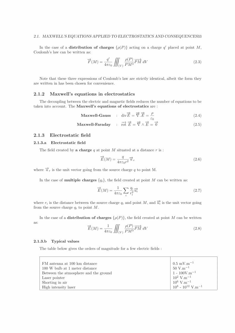
2.1.3.b Typical values
The table below gives the orders of magnitude for a few electric fields :
FM antenna at 100 km distance 0.5 mV.m−1
100 W bulb at 1 meter distance 50 V.m−1
Between the atmosphere and the ground 1 - 100V.m−1
Laser pointer 102 V.m−1
Shorting in air 106 V.m−1
High intensity laser 108 - 1012 V.m−1

34 CHAPTER 2. Electrostatics
2.1.3.c Conservation of charge
The continuity equation (or law of conservation of charge), in statics, gives:
div−→J = 0 (2.9)
−→J is then a vector with conservative flux.
Figure 2.1: Flux tube for the current density.
♦ Proof : Figure 2.1 shows a flux tube for the current density. This means that for all points on
non-hatched surface of (Σ),−→J .−→dS = 0. In other words, no current density goes in or out of the
tube except at the two ends S1 and S2. Let us moreover suppose that the flux tube is sufficiently
small to have−→J = J1
−→n1 at all points of S1, with−→n1 the outgoing normal to S1, and
−→J = J2
−→n2 atall points of S2, with
−→n2 the outgoing normal to S2. Then :
0 =
˚
(V )
div−→J
=
‹
(S1)+(Σ)+(S2)
−→J .−→dS
=
¨
(S1)
−→J .−→dS +
¨
(Σ)
−→J .−→dS +
¨
(S2)
−→J .−→dS
= J1S1 − J2S2
Hence J1S1 = J2S2. The flux of current density going through S1 is conserved when going out ofS2.
This property is found for all vectors−→A having div
−→A = 0.
2.1.3.d Gauss’ law
Let us consider a closed surface (S) delimiting a volume (V ) which contains a charge volumedensity ρ and a total charge Qint. Maxwell-Gauss’s equation gives Gauss’ law:
‹
(S)
−→E .−→dS =
˚
(V )
ρ
ε0dV =
Qint
ε0(2.10)
This relation is one of the most useful relations in electrostatics. As we will see in section 2.2, alongwith the use of symmetries and invariances, it allows to determine the electric field in numeroussimple situations.
2.1. MAXWELL’S EQUATIONS APPLIED TO ELECTROSTATICS AND CONSEQUENCES35
2.1.3.e Circulation of electrostatic field
Faraday’s law in electrostatics gives the circulation of electrostatic field :
˛
(C)
−→E .−→dl = 0 (2.11)
There is no work of the electrostatic force around a circular contour.
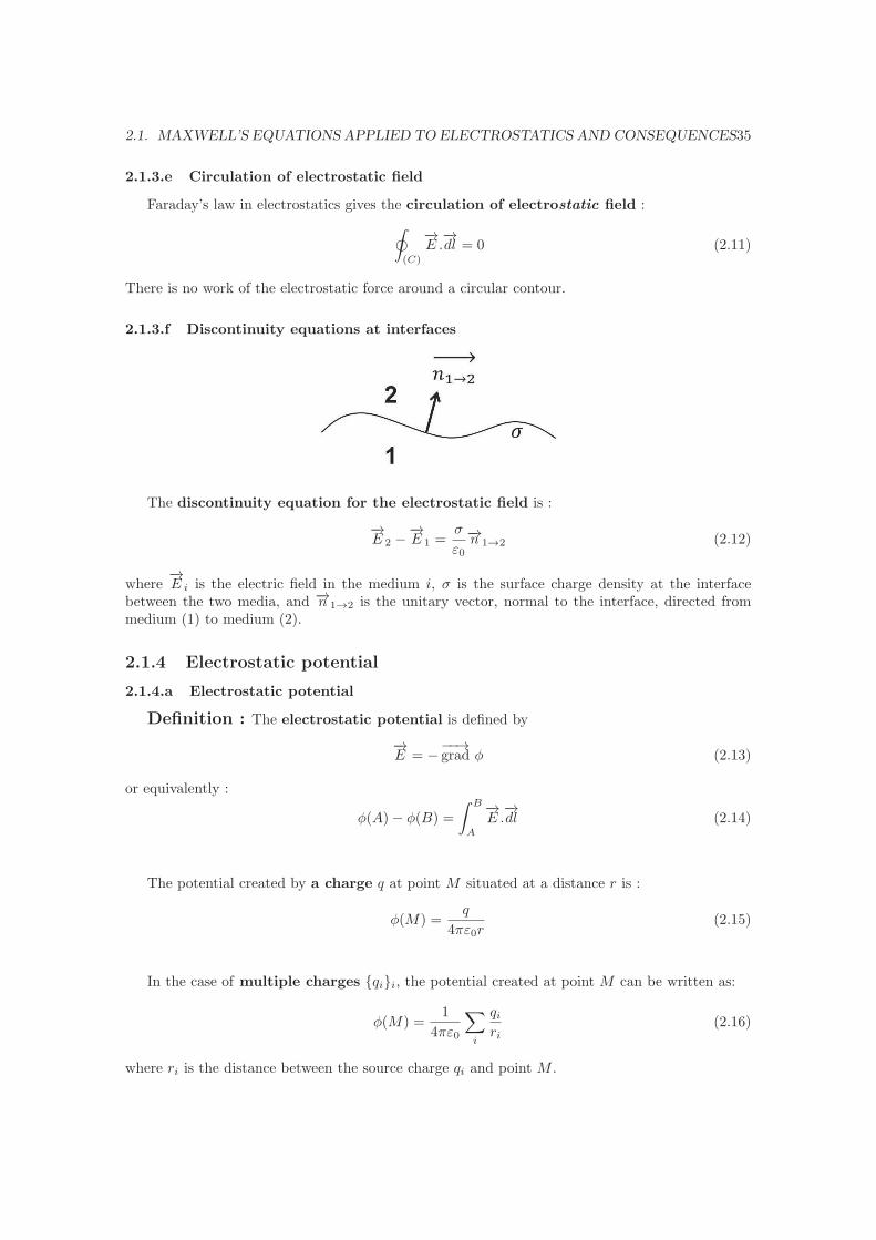
2.1.3.f Discontinuity equations at interfaces
The discontinuity equation for the electrostatic field is :
−→E 2 −
−→E 1 =
σ
ε0
−→n 1→2 (2.12)
where−→E i is the electric field in the medium i, σ is the surface charge density at the interface
between the two media, and −→n 1→2 is the unitary vector, normal to the interface, directed frommedium (1) to medium (2).
2.1.4 Electrostatic potential
2.1.4.a Electrostatic potential
Definition : The electrostatic potential is defined by
−→E = −
−−→grad φ (2.13)
or equivalently :
φ(A)− φ(B) =
ˆ B
A
−→E .−→dl (2.14)
The potential created by a charge q at point M situated at a distance r is :
φ(M) =q
4πε0r(2.15)
In the case of multiple charges {qi}i, the potential created at point M can be written as:
φ(M) =1
4πε0
∑
i
qiri
(2.16)
where ri is the distance between the source charge qi and point M .

36 CHAPTER 2. Electrostatics
In the case of a distribution of charges {ρ(P )}, the potential created at point M can bewritten as:
φ(M) =1
4πε0
˚
(V )
ρ(P )
PMdV (2.17)
⋆ Note : The electrostatic potential φ(r) of a group of charges vanishes at infinity. This is theorigin of the convention we will often use :
φ(r)→ 0 when r → +∞ (2.18)
2.1.4.b Potential propagation
In electrostatics, the potential propagation (see section 1.3.4) is written under the form ofPoisson’s equation :
△φ = −ρ
ε0(2.19)
In the specific case where there is no charge (ρ = 0), the propagation equation reduces toLaplace’s equation :
△φ = 0 (2.20)
The Poisson (or Laplace) equation will have an unique solution φ if boundary conditions arespecified on a closed surface :
– Either the potential is defined on a closed surface. This is called the Dirichlet boundary
condition.– Or the electric field is defined on a closed surface. This is called the Neumann boundary
condition.
♦ Proof : Let us suppose that φ1 and φ2 obey to the same Poisson equation △φ = − ρε0
inside avolume (V ). Let :
U = φ2 − φ1
Let us impose Dirichlet boundary condition on the closed bounding surface (S) of the volume (V ).Then, inside (V ) :
△U = △φ2 −△φ1 = −ρ
ε0+
ρ
ε0= 0
and on (S), U = 0.We now need to prove Green’s first identity :
˚
(V )
(
ξ△ψ +−−→grad ξ.
−−→grad ψ
)
dV =
‹
(S)
ξ∂ψ
∂ndS
For this, let us apply the divergence theorem (˝
(V )div−→AdV =
‚ −→A.−→dS =
‚ −→A.−→n dS) to
−→A =
ξ−−→grad ψ :
˚
(V )
div(
ξ−−→grad ψ
)
dV =
‹
(S)
(
ξ−−→grad ψ
)
.−→n dS
˚
(V )
(
ξ△ψ +−−→grad ξ.
−−→grad ψ
)
dV =
‹
(S)
ξ∂ψ
∂ndS
2.1. MAXWELL’S EQUATIONS APPLIED TO ELECTROSTATICS AND CONSEQUENCES37
Now, let us apply Green’s first identity to ξ = ψ = U :
˚
(V )
(
U△U +(−−→grad U
)2)
dV =
‹
(S)
U∂U
∂ndS
Given the boundary conditions and the fact that △U = 0 in (V ) :
˚
(V )
(−−→grad U
)2
dV = 0
which means that−−→grad U = 0 inside (V ). Hence U is constant in (V ) and since U = 0 on (S),
U = 0 in all (V ). Therefore φ1 = φ2 and the solution is unique.
2.1.5 Field lines and equipotential surfaces
2.1.5.a Field lines
Definition : Electric field lines are the lines that are, at all points in space, tangent to
the electric field−→E . They can be determined through the relation :
−→E (M) ∧
−→dl =
−→0 (2.21)
where−→dl is an infinitesimal vector along the field line, centered around point M .
2.1.5.b Equipotential surfaces
Definition : Equipotential surfaces are surfaces where the scalar potential φ(M) isconstant.
2.1.5.c Properties
Property #1 : The electrostatic potential and the electric field reproduce all symmetries
and invariances of the charge distribution ρ(P ) that create this potential and this field.
Property #2 : Equipotential surfaces are normal to the electric field−→E at all points and
therefore are normal to the field lines.
♦ Proof : Equation 2.14 shows that if points A and B are points sufficiently close to one anotheron the same equipotential surface :
φ(A)− φ(B) = 0 =
ˆ B
A
−→E .−→dl
with−→dl defining the equipotential surface. Therefore
−→E⊥
−→dl .
This relation is only valid in electrostatics. In the general case, the term in ∂−→A∂t has to be
taken into account.
Property #3 : Field lines cannot be closed. They begin and end either on a charge or at
infinity.
♦ Proof : Let us suppose that (C) is a closed field line. In that case, by definition of a field line
(−→E parallel to
−→dl) :
˛
(C)
−→E .−→dl =
˛
(C)
E dl ≥ 0
38 CHAPTER 2. Electrostatics
However, equation 2.11 gives :˛
(C)
−→E .−→dl = 0
These two conditions impose :¸
(C)
−→E .−→dl = 0 and therefore
−→E =
−→0 .
Property #4 : In regions with no charge,−→E conserves its flux : div
−→E = 0
♦ Proof : The proof is the same as the one given in section 2.1.3.c.
In other words, when the field lines move apart, the norm of−→E diminishes.
Property #5 : The electrostatic potential cannot be maximum nor minimum in a point
where there is no charge.
♦ Proof : Let A be a point where the potential φ is maximum. Then there exists a volume Vdelimited by a surface Σ such that all points M in this volume have :
∀M φ(M) ≤ φ(A)
Let us chose the volume V such that Σ is an equipotential surface. Then :
‹
(Σ)
−→E .−→dS > 0
unless−→E =
−→0 . But Gauss’ law also gives :
‹
(Σ)
−→E .−→dS =
Qint
ε0
So that Qint > 0.
2.1.6 Energetics in electrostatic
2.1.6.a Electrostatic energy
Definition : The volume density of electrostatic energy is given by :
u =ε0E
2
2(2.22)
This is a particular case of equation 1.24.
As a consequence, the total electrostatic energy U in a volume V can be written as :
U =
˚
(V )
u dV
U =1
2
˚
(V )
ε0E2 dV ≥ 0 (2.23)
This energy is always positive. It implies that φ(+∞) = 0 and that the presence of a field adds
energy to the system.

2.2. EXAMPLES OF USUAL CHARGE DISTRIBUTIONS 39
2.1.6.b Relation with the electrostatic potential
In section 1.3.2, we have seen that qφ corresponds to the potential energy of a charge q placedin a potential φ. In other words, if the charge q is brought from infinity (where φ = 0) to a pointx where the electrostatic potential is φ, the work done on the charge is
W = qφ
If the potential is created by an ensemble of N charges qj (j = 1, 2, ..., N) at positions −→rj , thenthe potential energy created on the charge qi placed at position −→ri is :
Wi =qi
4πε0
N∑
j=1
qj|−→rj −
−→ri |
Then, the total potential energy for all charges is :
W =N∑
i=1
Wi =1
4πε0
N∑
i=1
∑
j<i
qiqj|−→rj −
−→ri |=
1
8πε0
∑
(i,j)
qiqj|−→rj −
−→ri |
where the terms i = j are not included in the sum. This can be rewritten as :
W =1
2
∑
i
qiφi
where φi =1
4πε0
∑
jqj
|−→rj−−→ri |
is the potential created by all other charges on qi at−→ri .
2.2 Examples of usual charge distributions
2.2.1 Example #1 : Uniformly charged infinite wire
Let us consider an uniformly charged infinite wire as schematized figure 2.2.1. The uniformlinear charge density is λ. Let us determine the electrostatic field and potential created by such asystem.
Figure 2.2: Uniformly charged infinite wire.
40 CHAPTER 2. Electrostatics
The problem is of cylindrical symmetry. We will therefore use the cylindrical coordinates. Sincethe charge distribution ρ(r, �θ, �z), and the electrostatic potential conserves the symmetries of thecharge distribution, φ(r, �θ, �z). Hence :
−→E = −
−−→grad φ = −
dφ
dr−→ur
Another way of obtaining this result is to say that all pointM of space belongs to two symmetry
planes : the one defined by {−→ur,−→uz} and the one defined by {−→ur,
−→uθ}. Since at these points M the
electric field must belong to all symmetry planes,−→E ‖ −→ur.
We will apply Gauss’ law on the following Gauss surface : a cylinder of height h and radius r :
‹
(SGauss)
−→E .−→dS =
Qint
ε0¨
(S1)
−→E .−→dS +
¨
(S2)
−→E .−→dS +
¨
(Slat)
−→E .−→dS =
λh
ε0
0 + 0 + 2πrhE(r) =λh
ε0
E(r) =λ
2πε0r−→E =
λ
2πε0r−→ur
From the relation between φ and−→E , one derives : φ = − λ
2πε0ln(r)+constant. If one imposes φ = 0
on the conductor, one obtains : φ = − λ2πε0
ln(
ra
)
.
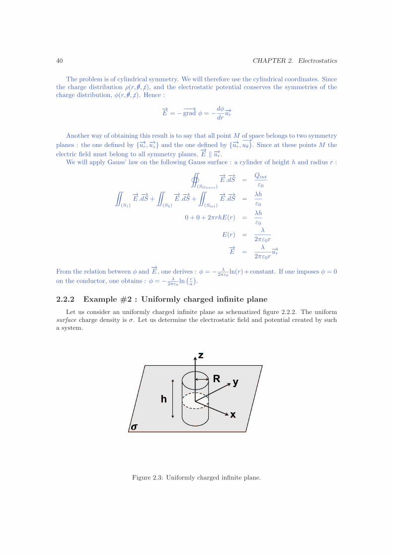
2.2.2 Example #2 : Uniformly charged infinite plane
Let us consider an uniformly charged infinite plane as schematized figure 2.2.2. The uniformsurface charge density is σ. Let us determine the electrostatic field and potential created by sucha system.
Figure 2.3: Uniformly charged infinite plane.
2.2. EXAMPLES OF USUAL CHARGE DISTRIBUTIONS 41
The problem is of cartesian symmetry. We will therefore use the cartesian coordinates. Sinceρ(�x, �y, z), and the electrostatic potential conserves the symmetries of the charge distribution,φ(�x, �y, z). Hence :
−→E = −
−−→grad φ = −
dφ
dz−→uz
Moreover, the {Oxy} plane is a symmetry plane, so that - using−→E ‖ −→uz :
−→E (SP(x, y, z)) = SP
(−→E (x, y, z)
)
−→E (−x, y, z) = SP
(−→E (x, y, z)
)
−→E (−x, y, z) = −
−→E (x, y, z)
We will apply Gauss’ law on the following Gauss surface : a cylinder of height h and radius R,centered around the {Oxy} plane :
‹
(SGauss)
−→E .−→dS =
Qint
ε0¨
(S1)
−→E .−→dS +
¨
(S2)
−→E .−→dS +
¨
(Slat)
−→E .−→dS =
σπR2
ε0
E(z)πR2 − E(−z)πR2 + 0 =σπR2
ε0
E(z) =σ
2ε0−→E =
σ
2ε0
−→uz
From the relation between φ and−→E , one derives : φ = − σ
2ε0z + constant. If one imposes φ = 0 on
the conductor, one obtains : φ = − σ2ε0z.
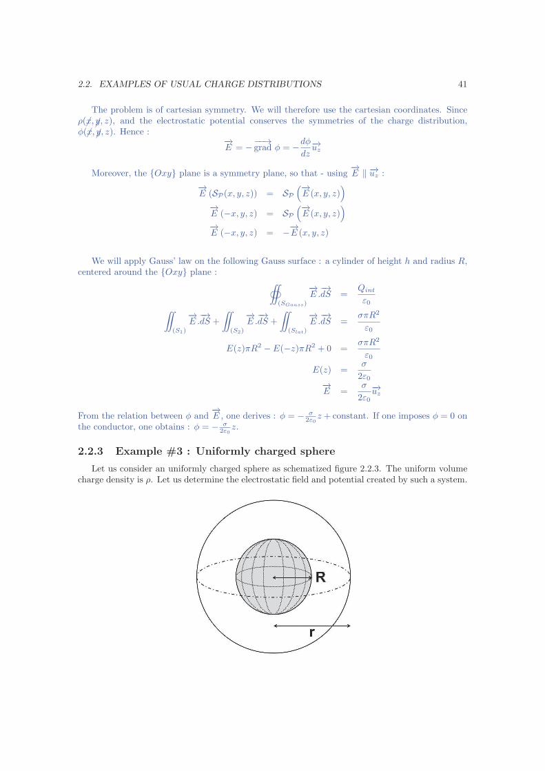
2.2.3 Example #3 : Uniformly charged sphere
Let us consider an uniformly charged sphere as schematized figure 2.2.3. The uniform volumecharge density is ρ. Let us determine the electrostatic field and potential created by such a system.

42 CHAPTER 2. Electrostatics
Figure 2.4: Uniformly charged sphere.
The problem is of spherical symmetry. We will therefore use the spherical coordinates. Sincethe charge distribution ρ(r, �θ,�ϕ ), and the electrostatic potential conserves the symmetries of thecharge distribution, φ(r, �θ,�ϕ ). Hence :
−→E = −
−−→grad φ = −
dφ
dr−→ur
Another way of obtaining this result is to say that all planes containing −→ur are symmetry planes.
Since the electric field must belong to all symmetry planes,−→E ‖ −→ur.
We will apply Gauss’ law on the following Gauss surface : a sphere of radius r :
‹
(SGauss)
−→E .−→dS =
Qint
ε0‹
(SGauss)
E−→ur.dS−→ur =
4πR3ρ
3ε0ˆ π
θ=0
ˆ 2π
ϕ=0
E(r)r2sinθdθ dϕ =4πR3ρ
3ε0
E(r)4πr2 =4πR3ρ
3ε0
E(r) =R3ρ
3ε0r2
−→E =
R3ρ
3ε0r2−→ur
From the relation between φ and−→E , one derives : φ = − ρR3
3ε0r+ constant. If one imposes φ = 0 on
the conductor, one obtains : φ = − ρR3
3ε0r+ ρR2
3ε0.
2.3 Conductors
2.3.1 Electrostatic field and potential inside a conductor
An electrical conductor is a material that contains numerous “free” electrons. This means thatthese electrons - usually from the outer shells of the atoms constituting the conductor - are able tofreely move inside the material. In particular, if a conductor is submitted to an external electric
field−→E ext, the electrons will be set in motion by this field and will only stop once equilibrium is
achieved, that is to say that−→E total =
−→0 .
Property #1 : The electrostatic field inside a conductor is zero :
−→E conductor =
−→0 (2.24)
It follows that the scalar potential φ inside a an electrical conductor is constant.Property #2 : An electrical conductor is an equipotential region.
φ = constant (2.25)

2.3. CONDUCTORS 43
2.3.2 Charges inside a conductor
Let us consider an electrical conductor. As we have seen, the electrostatic field inside the
conductor−→E int is zero :
−→E int =
−→0 . Then Maxwell-Gauss equation gives that the volume charge
density inside the conductor is ρconductor = ǫ0div−→E = 0 :
Property #3 : In a conductor at equilibrium, there are no volume charges. All excess
charges are at the surface of the conductor :
ρconductor = 0 (2.26)
In practice, all charges accumulate on a few atomic layers at the surface of the conductor. Theseare therefore surface charges.
2.3.3 Electric field at the vicinity of a conductor
Let us consider the conductor schematized on the opposite figure anduse the discontinuity equations at its interface with another medium
where reigns an electrostatic field−→E ext :
−→E ext −
−→E int =
−→E ext =
σsǫ0
−→uz
Thus, under the action of an external magnetic field, charges accumulate at the surface of theconductor. These surface charge, in turn, create an electric field such that, in the conductor thetotal field is zero.
Property #4 : Outside, but at the immediate vicinity of an electrical conductor, the external
electric field is :−→E ext =
σsǫ0
−→n (2.27)
where −→n is the vector normal to the conductor surface.
2.3.4 Application #1 : radiation pressure for a conductor placed in a
zero electric field
We here consider the point Me external to the conductor, such asindicated in the opposite figure. One can decompose the electric fieldat point Me into two components :
i. The field created by the surface charges which immediately facethe pointMe on the conductor, which are on the surface dS. SinceMe can be taken infinitely close to the conductor, while still being
exterior to the conductor, it “sees” the surface dS under a solid angle of approximately2π, that is to say that the surface charges appear, for Me to be distributed on an infiniteplane. This component is therefore equal to the field created by an uniformly charged plane
:−→E1 = σs
2ǫ0
−→uz.
ii. The field−→E2 created by all other surface charges on the conductor.
We will call Σ the surface of the conductor from which the surfacedS is extracted.
Since the field in Me is :−→E =
−→E1 +
−→E2 =
σsǫ0
−→uz
44 CHAPTER 2. Electrostatics
one deduce that all charges on Σ create a field at point Me :
−→E2 =
σs2ǫ0
−→uz
Now, let us calculate the force exerted by the surface charges of Σ on those on dS :
−→dF = dq
−→E2(Me) = σsdS ×
σs2ǫ0
−→uz
This force is equivalent to a pressure since proportional to dS. The pressure therefore is P =σ
2
s
2ǫ0.
This pressure is called the radiation pressure.⋆ A few comments :
– To say that the field−→E1 is the same than the one created by an infinite charged plane might
look like an approximation. However, it can be shown that it is the exact result. Indeed, theelectric field outside the conductor is :
−→E ext =
−→E1(Me) +
−→E2(Me) =
σsǫ0
−→uz
The field inside the conductor (at Mi) can also be decomposed into a component due to the
field created by dS :−→E1(Mi) = −
−→E1(Me), and a component due to the field created by Σ
which is equal to−→E2(Mi) =
−→E2(Me)
−−→Eint =
−→0 = −
−→E1(Me) +
−→E2(Me)
Hence :−→E1(Me) =
σs2ǫ0
−→uz
−→E2(Me) =
σs2ǫ0
−→uz
– It is interesting to note that the field in the vicinity of a conductor, at pointMe only dependson the local surface charge density σs(Me), i.e. the one carried by the small conductor surfacedS. The charges of the rest of the conductor (on Σ), “organize” themselves so as to cancel,inside the conductor, the field created by those carried by dS.
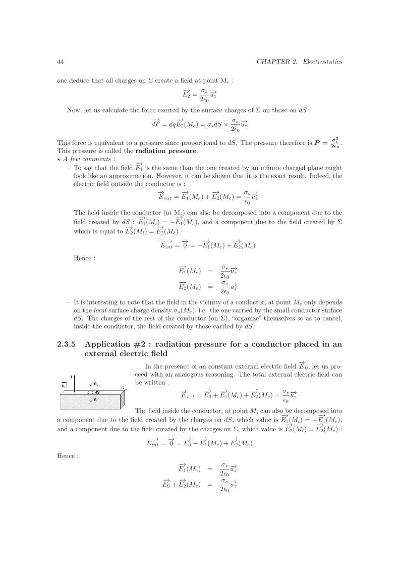
2.3.5 Application #2 : radiation pressure for a conductor placed in an
external electric field
In the presence of an constant external electric field−→E 0, let us pro-
ceed with an analogous reasoning. The total external electric field canbe written :
−→E ext =
−→E0 +
−→E1(Me) +
−→E2(Me) =
σsǫ0
−→uz
The field inside the conductor, at pointMi can also be decomposed into
a component due to the field created by the charges on dS, which value is−→E1(Mi) = −
−→E1(Me),
and a component due to the field created by the charges on Σ, which value is−→E2(Mi) =
−→E2(Me) :
−−→Eint =
−→0 =
−→E0 −
−→E1(Me) +
−→E2(Me)
Hence :−→E1(Me) =
σs2ǫ0
−→uz
−→E0 +
−→E2(Me) =
σs2ǫ0
−→uz

2.3. CONDUCTORS 45
This time, the charges on Σ ”organize” themselves so as to exactly compensate the field createdby charges on dS, taking into account the external electric field. The radiation pressure exerted on
dS corresponds to the force exerted on the surface charges on dS due to the external field−→E0 and
due to the charges on Σ. Its expression still is P =σ
2
s
2ǫ0.
N.B. 1 : If−→E0 =
−→0 , the result is the same as in the previous paragraph.
N.B. 2 : A conducting object placed within an uniform electrostatic field−→E0 charges itself at
its surface, so that the electric field outside but at the immediate vicinity of this object is notnecessarily uniform !N.B. 2 : In this particular case, one cannot apply the principle of superposition in a simple manner
(i.e. a charged conductor in−→E0 = a charged conductor in zero field + a static field). This is due
to the fact that the boundary conditions, at infinity in particular, are not trivial.
2.3.6 High voltage breakdown
Let us now mention the dependence of the field with respect to shape. More specifically, wewill qualitatively discuss the field near a sharp conductor.
First, let us remark that if one takes two spheres of radius R1 and R2 ≪ R1, both charged withQ. According to the calculation made section 2.2.3, the electric fields respectively verify :
4πR21E1 =
Q
ε0
4πR22E2 =
Q
ε0
Hence :
E1 =Q
4πR21ε0
E2 =Q
4πR22ε0
As can be seen, the field near the smaller sphere is larger than the one in the vicinity of the
larger sphere. In other words, any sharp point in a material has a large electric field near its surface.This result is important for practical realizations. Indeed, above a certain electric field, the air
will break down. In this case, a loose charge - whether electron or ion - will be accelerated by thefield, will then collide with an atom, knocking out an electron of this atom. The additional ion andelectron will, in turn, be accelerated and a cascade process will begin, resulting in a great numberof charged particules in the air. Their motion creates a discharge or a spark.
♣ Application #1 : If one wants to put a conductor to a high potential, one must avoid theconductor surface to have any sharp surface features. Otherwise the air will discharge towards thistip.
♣ Application #2 : This field effect is used by field-emission microscopy to image the material ofa thin needle 1. This technique has enabled, since 1955, to image materials with a resolution of afew Angstroms, well before the advent of local probes such as the Scanning Tunneling Microscope(STM) or the Atomic Force Microscopie (AFM).
1. For explanations on the working principle, see for example : Field Ion Microscopy, B. Gault et al., “Atom
Probe Microscopy”, accessible on the Internet.

46 CHAPTER 2. Electrostatics
2.4 Electrostatic dipole
The notion of electrostatic dipole is important both in physics and chemistry. Indeed, inchemistry, it can model the behavior of polar molecules - such as HCl for instance - under amagnetic field. In physics, we will see in the next chapter that it is at the basis of the microscopicdescription of dielectric materials.
2.4.1 Definition
Definition : An electrostatic dipole is a distribution of static charges {qi}i placed atpoints Pi, of finite spatial extension δ around point A, and for which the electric dipole moment−→p (in C.m) is non zero :
−→p =∑
i
qi−−→APi (2.28)
♣ Example : The simplest electrostatic dipole is a charge doublet {+q,−q} (q > 0). If +q is placed
at point P , −q at point N , and A the center point of [NP ], and−−→NP = d −→u :
−→p = +q−→AP − q
−−→AN = q
−−→NP = qd −→u
Note : A dipole which moment is not affected by the application of an external electric field iscalled rigid.
Definition : The dipole approximation consists in considering the effect of an electrostaticdipole at point M such that r = AM ≫ δ.
In other words, one neglects the spatial extension δ of the real charge distribution {qi}i aroundpoint A and replaces it by a dipole −→p placed in A. Therefore, a dipole can always be modeled bytwo “equivalent” charges of opposite sign, centered at point A.
2.4.2 Electrostatic field and potential created by an electrostatic dipole
2.4.2.a Electrostatic potential created by an electrostatic dipole
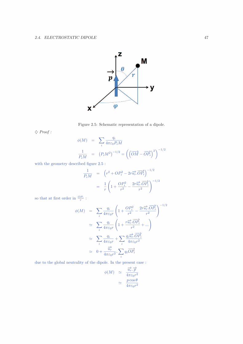
In the dipole approximation, the electrostatic potential created at point M by an electrostatic
dipole −→p placed at point A such that−−→AM = r−→u , with −→u an unit vector, is :
φ(M) =−→p .−→u
4πε0r2(2.29)
2.4. ELECTROSTATIC DIPOLE 47
Figure 2.5: Schematic representation of a dipole.
♦ Proof :
φ(M) =∑
i
qi4πε0PiM
1
PiM=
(
PiM2)−1/2
=
(
(−−→OM −
−−→OPi
)2)−1/2
with the geometry described figure 2.5 :
1
PiM=
(
r2 +OP 2i − 2r−→ur.
−−→OPi
)−1/2
=1
r
(
1 +OP 2
i
r2−
2r−→ur.−−→OPi
r2
)−1/2
so that at first order in OPi
r :
φ(M) =∑
i
qi4πε0r
(
1 +OP 2
i
r2−
2r−→ur.−−→OPi
r2
)−1/2
≃∑
i
qi4πε0r
(
1 +r−→ur.
−−→OPi
r2+ ...
)
≃∑
i
qi4πε0r
+∑
i
qi−→ur.−−→OPi
4πε0r2
≃ 0 +−→ur
4πε0r2.∑
i
qi−−→OPi
due to the global neutrality of the dipole. In the present case :
φ(M) ≃−→ur.−→p
4πε0r2
≃p cos θ
4πε0r2

48 CHAPTER 2. Electrostatics
2.4.2.b Electrostatic field created by an electrostatic dipole
In the dipole approximation, the electrostatic field created at pointM by an electrostatic dipole−→p placed at point A such that
−−→AM = r−→u , with −→u an unit vector, is :
−→E (M) =
3 (−→p .−→u ) .−→u −−→p
4πε0r3(2.30)
♦ Proof : Taking the same definitions as above :
V (M) ≃p cos θ
4πε0r2−→E = −
−−→grad φ
−→E ≃
∣
∣
∣
∣
∣
∣
2p cos θ4πε0r3p sin θ4πε0r3
0
Moreover :
3 (−→p .−→u ) .−→u −−→p
4πε0r3=
3p cos θ−→ur − p cos θ−→ur + p sin θ−→uθ
4πε0r3
=
∣
∣
∣
∣
∣
∣
2p cos θ4πε0r3p sin θ4πε0r3
0
2.4.2.c Field lines and equipotential surfaces for an electrostatic dipole
From equation 2.29, the equipotential surfaces are such that r2 = k cos θ with k a contant.Field lines are obtained by taking, at all points, the normal to the equipotential surfaces. Fieldlines and equipotential surfaces are schematized figure 2.6.
2.4. ELECTROSTATIC DIPOLE 49
Figure 2.6: Schematic representation of the equipotential surfaces and field lines of adipole. Taken from http://www.pstcc.edu/departments/natural_behavioral_sciences/Web%
20Physics/Experim%2001.htm. The dipole is here modeled by two opposite charges.
Note : Bear in mind that the above expressions are obtained in the dipole approximation, whichmeans that they are not valid within the charge distribution.
2.4.3 Mechanical action of an external electric field on a electrostatic
dipole
2.4.3.a Electrostatic dipole in an external electric field
In the dipole approximation, an electrostatic dipole −→p , of center A, placed in an external electric
field−→E is submitted to forces such that :
– the resultant force is :−→F (A) =
(
−→p .−−→gradA
)−→E (A)
– the angular momentum is :−→M(A) = −→p ∧
−→E (A)
♦ Proof : Let us first calculate the resultant force (first order approximation) :
−→F (A) =
∑
i
qi−→E (Pi)
≃
∣
∣
∣
∣
∣
∣
∣
∣
∣
∑
i qi
(−→Ex(A) +
−−→APi.
−−→grad Ex(A)
)
∑
i qi
(−→Ey(A) +
−−→APi.
−−→grad Ey(A)
)
∑
i qi
(−→Ez(A) +
−−→APi.
−−→grad Ez(A)
)
≃
∣
∣
∣
∣
∣
∣
∣
∑
i qi−−→APi.
−−→grad Ex(A)
∑
i qi−−→APi.
−−→grad Ey(A)
∑
i qi−−→APi.
−−→grad Ez(A)
≃(
−→p .−−→gradA
)−→E (A)
Then the angular momentum is :
M(A) =∑
i
−−→APi ∧ qi
−→E (Pi)
≃∑
i
−−→APi ∧ qi
−→E (A)
≃ −→p ∧−→E (A)
2.4.3.b Application in the case of a rigid electrostatic dipole
If the considered dipole is rigid, the charges composing the dipole do not move with respect toone another. −→p is then constant in norm. Then the resulting force is :
−→F (A) = −
−−→gradA (Ue)
Ue = −−→p .−→E (A)

50 CHAPTER 2. Electrostatics
♦ Proof :
Ue =∑
i
qiφ(Pi)
=∑
i
qiφext(Pi) +∑
i
qiφint(Pi)
=∑
i
qi
(
φext(A) +−−→APi.
−−→grad φext(A)
)
+ constant taken to be 0
= 0 +−→p .(
−−→E (A)
)
The force exerted on the dipole therefore derives from the potential energy Ue. Then, the dipole
tends to align with the external field−→E (M).
♣ Example #1: Solvation of ions - Some solvent molecules, such as water for instance, are polar,which means they possess an electrostatic dipole moment (figure 2.4.3.b). When ions are dissolvedin a solvent, the solvent molecules organize themselves around the ion in order to minimize theelectrostatic energy (figure 2.4.3.b). In chemistry, the standard unit for molecular dipole momentsis the Debye (1 D = 3.33×10⁻³⁰ C.m). A water molecule has a dipole moment of 1.83 D.
Figure 2.7: Schematization of electrostatic dipole moment of a molecule of water. Taken from http:
//guweb2.gonzaga.edu/faculty/cronk/CHEM101pub/L18-index.cfm?L18resource=water.
Figure 2.8: Schematization of the hydration of Na+ by water molecules. Taken from http://www.
science.uwaterloo.ca/~cchieh/cact/applychem/hydration.html.
♣ Example #2: Van der Waals interactions - Van der Waals forces 2 group different forces, allproportional to 1/r7. You will derive some of these in the Electrostatics exercise sheet. These
2. These intermolecular forces have first been predicted by the Dutch physicist J.D. van der Waals in his PhD
thesis, defended in 1873.
2.5. METHODS IN ELECTROSTATICS 51
forces originate from dipole-dipole interactions 3 and explain most of intermolecular interactions.They have numerous applications, from scotch tape to biology 4 and including chemistry or polymerscience.
2.5 Methods in electrostatics
There are numerous solving methods in electrostatics which we will not review here 5. For thepurpose of this course, you will mainly be using one of the following methods :
– Directly compute the electric field using symmetries, invariances and :
−→E =
1
4πε0
˚
(V )
ρ
r2−→u dV
– Directly compute the electrostatic potential using symmetries, invariances and :
φ =1
4πε0
˚
(V )
ρ
rdV
– Determine the electric field using symmetries, invariances and Gauss theorem :
‹
−→E .−→dS =
Qint
ε0
Also note that, for a problem with spherical symmetry, the method of separation of variables -as seen in Quantum Mechanics for example - can be used.
2.5.1 Method of images
We will however detail one important method : the Method of images. This method can beuseful in the case of one or a few point charges in the presence of boundary surfaces that imposediscontinuities of the electric field. For instance, point charges in the presence of conductors.
The method consists in replacing the real problem with discontinuities - for eg. the conductingplanes - by an equivalent problem in an enlarged region, with no boundaries, where one or a fewvirtual charges - the image charges -, are placed outside the region of interest so that :
1. these image charge simulate the boundary conditions ;
2. the electrostatics equation - the Poisson equation - remain unchanged in the region of interest.
The virtual problem with image charges is usually easier to solve. Then, thanks to the unicitytheorem (see section 1.6.2), the electric field that is found for the equivalent-charge problem is thesame, in the region of interest, than the one in the real problem.
♣ Example : single charge in the presence of an infinite conducting plane
3. See exercise sheet on electrostatics.
4. See section 2.6
5. An introduction to those can be found in chapters 2, 3 and 4 of J.D. Jackson, Classical Electrodynamicsand
in chapters 5 to 8 of E. Weber, Electromagnetic Theory.
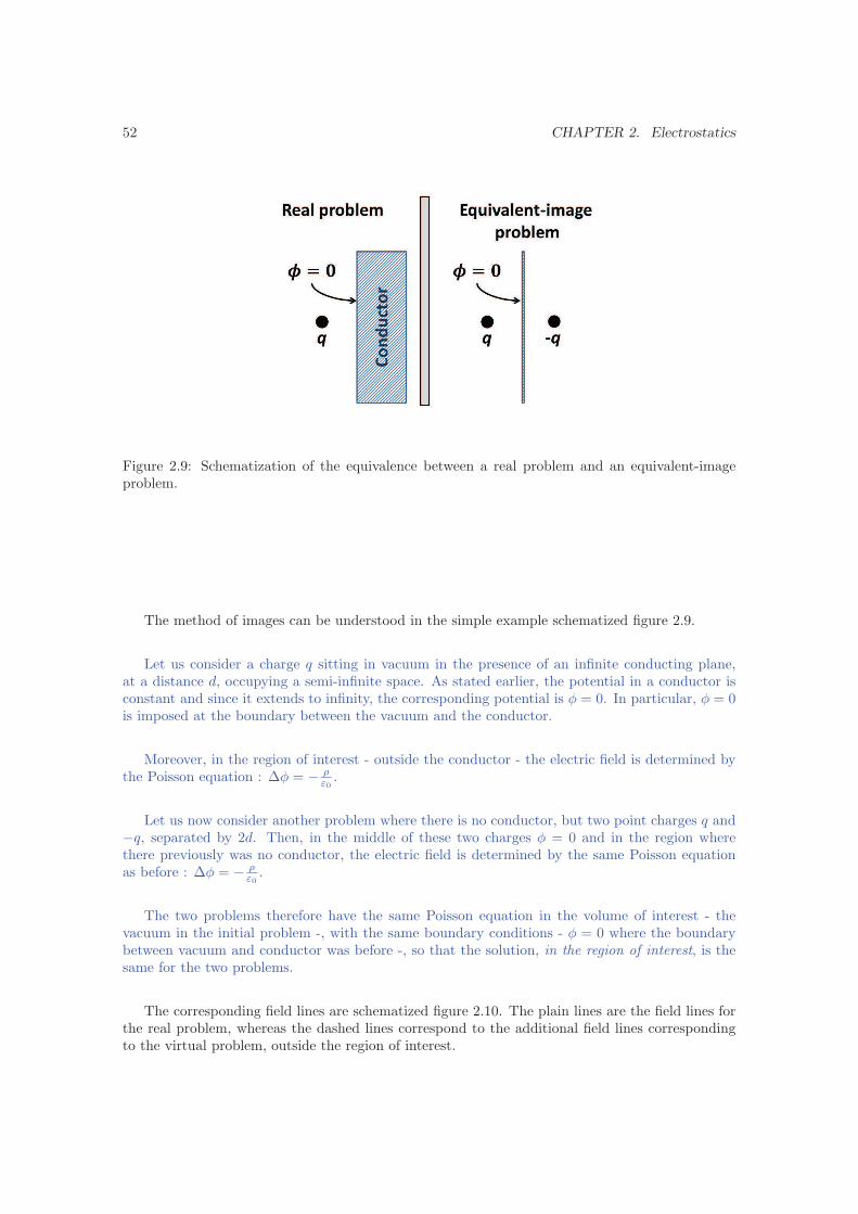
52 CHAPTER 2. Electrostatics
Figure 2.9: Schematization of the equivalence between a real problem and an equivalent-imageproblem.
The method of images can be understood in the simple example schematized figure 2.9.
Let us consider a charge q sitting in vacuum in the presence of an infinite conducting plane,at a distance d, occupying a semi-infinite space. As stated earlier, the potential in a conductor isconstant and since it extends to infinity, the corresponding potential is φ = 0. In particular, φ = 0is imposed at the boundary between the vacuum and the conductor.
Moreover, in the region of interest - outside the conductor - the electric field is determined bythe Poisson equation : ∆φ = − ρ
ε0.
Let us now consider another problem where there is no conductor, but two point charges q and−q, separated by 2d. Then, in the middle of these two charges φ = 0 and in the region wherethere previously was no conductor, the electric field is determined by the same Poisson equationas before : ∆φ = − ρ
ε0.
The two problems therefore have the same Poisson equation in the volume of interest - thevacuum in the initial problem -, with the same boundary conditions - φ = 0 where the boundarybetween vacuum and conductor was before -, so that the solution, in the region of interest, is thesame for the two problems.
The corresponding field lines are schematized figure 2.10. The plain lines are the field lines forthe real problem, whereas the dashed lines correspond to the additional field lines correspondingto the virtual problem, outside the region of interest.
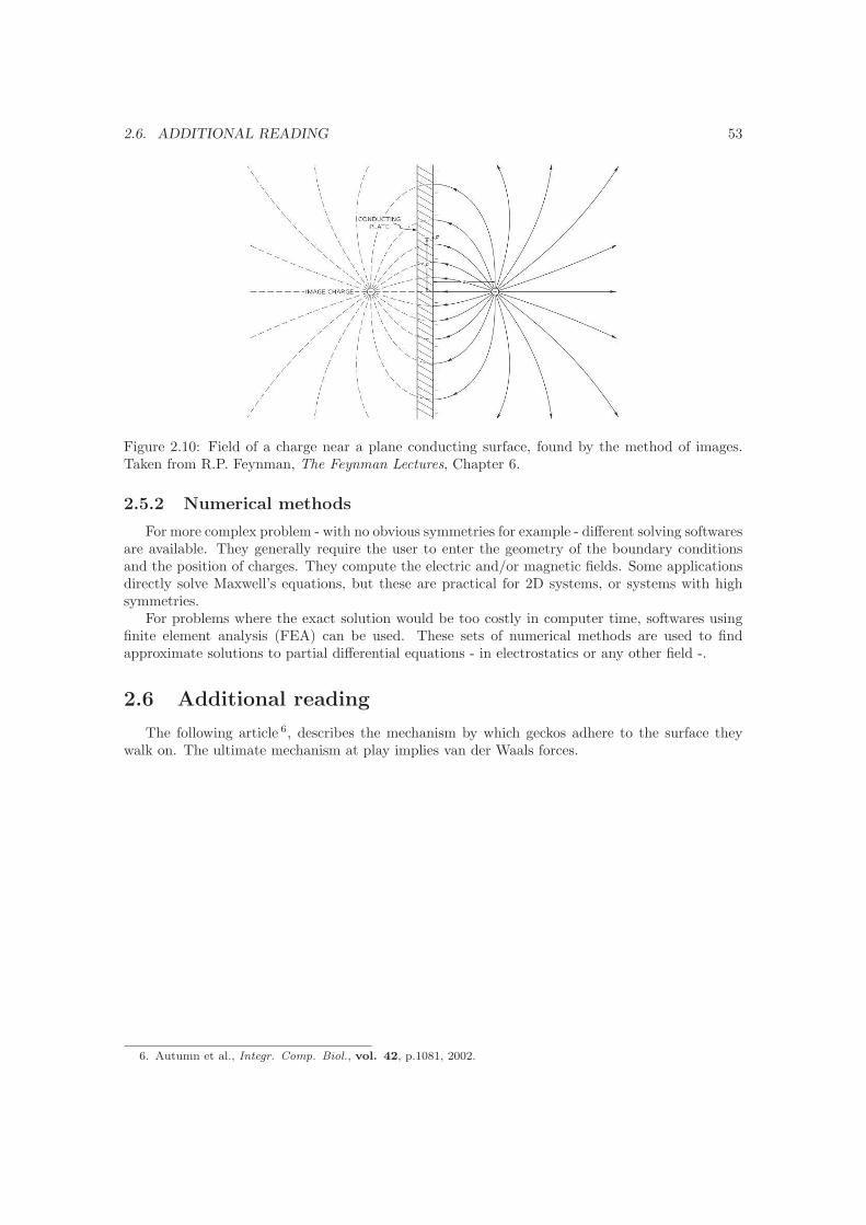
2.6. ADDITIONAL READING 53
Figure 2.10: Field of a charge near a plane conducting surface, found by the method of images.Taken from R.P. Feynman, The Feynman Lectures, Chapter 6.
2.5.2 Numerical methods
For more complex problem - with no obvious symmetries for example - different solving softwaresare available. They generally require the user to enter the geometry of the boundary conditionsand the position of charges. They compute the electric and/or magnetic fields. Some applicationsdirectly solve Maxwell’s equations, but these are practical for 2D systems, or systems with highsymmetries.
For problems where the exact solution would be too costly in computer time, softwares usingfinite element analysis (FEA) can be used. These sets of numerical methods are used to findapproximate solutions to partial differential equations - in electrostatics or any other field -.
2.6 Additional reading
The following article 6, describes the mechanism by which geckos adhere to the surface theywalk on. The ultimate mechanism at play implies van der Waals forces.
6. Autumn et al., Integr. Comp. Biol., vol. 42, p.1081, 2002.
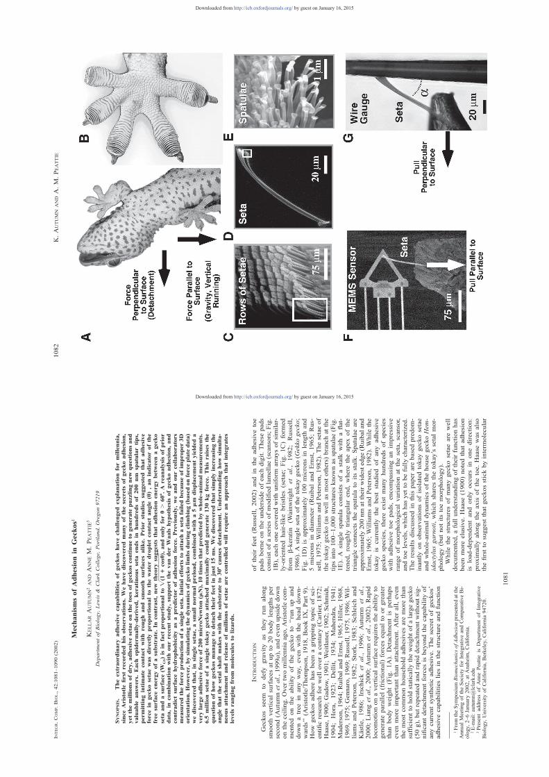
1081
INTEGR.COMP.BIOL.,42:1081–1090(2002)
MechanismsofAdhesionin
Geckos1
KELLARAUTUMN2ANDANNEM.PEATTIE
3
DepartmentofBiology,Lewis&
Clark
College,Portland,Oregon97219
SYNOPSIS.
Theextraordinaryadhesivecapabilitiesofgeckoshavechallengedexplanationformillennia,
sinceAristotlefirstrecordedhisobservations.Wehavediscoveredmanyofthesecretsofgeckoadhesion,
yetthemillionsofdry,adhesivesetaeonthetoesofgeckoscontinueto
generatepuzzlingnewquestionsand
valuable
answers.Eachepidermally-derived,keratinousseta
endsin
hundredsof200nm
spatulartips,
permittingintimate
contactwithroughandsm
ooth
surfacesalike.Priorstudiessuggestedthatadhesive
forcein
geckosetaewasdirectlyproportionalto
thewaterdropletcontactangle( u),anindicatorofthe
freesurfaceenergyofasubstrate.In
contrast,newtheorysuggeststhatadhesionenergybetweenagecko
seta
andasurface(W
GS)isin
factproportionalto
,andonlyfor
u.60
8.Areanalysisofprior
Ï(1
1cosu)
data,in
combinationwithourrecentstudy,supportthevanderWaalshypothesisofgeckoadhesion,and
contradictsurfacehydrophobicityasapredictorofadhesionforce.Previously,weandourcollaborators
measuredtheforceproductionofasingleseta.Initialeffortsto
attachaseta
failedbecause
ofimproper3D
orientation.However,bysimulatingthedynamicsofgeckolimbsduringclimbing(basedonforceplatedata)
wediscoveredthat,in
singlesetae,asm
allnormalpreload,combinedwitha5
mm
displacementyieldeda
verylargeadhesiveforceof200microNewton(mN),10timesthatpredictedbywhole-animalmeasurements.
6.5
millionsetaeofasingle
tokaygeckoattachedmaximallycould
generate
130kgforce.Thisraisesthe
questionofhowgeckosmanageto
detachtheirfeetin
just15ms.Wediscoveredthatsimplyincreasingthe
anglethatthesetalshaftmakeswiththesubstrate
to30
8causesdetachment.Understandinghowsimulta-
neousattachmentandrelease
ofmillionsofsetaearecontrolledwillrequireanapproachthatintegrates
levelsrangingfrom
moleculesto
lizards.
INTRODUCTION
Geckosseem
todefy
gravityastheyrunalong
smooth
verticalsurfacesatupto
20bodylengthsper
second(Autumnetal.,1999a),andevenupsidedown
ontheceiling.Overtwomillenniaago,Aristotlecom-
mentedontheabilityofthegeckoto
‘‘runupand
downatreein
anyway,evenwiththeheaddown-
wards’’(Aristotle/Thompson,1918,BookIX,Part9).
Howgeckosadhere
hasbeenagrippingtopicofsci-
entificresearchforwelloveracentury
(Cartier,1872;
Haase,1900;Gadow,1901;Weitlaner,1902;Schmidt,
1904;Hora,1923;Dellit,1934;Mahendra,1941;
Maderson,1964;RuibalandErnst,1965;Hiller,1968,
1969,1975;Gennaro,1969;Russell,1975,1986;Wil-
liamsandPeterson,1982;Stork,1983;Schleichand
Kastle,1986;Irschick
etal.,1996;Autumn
etal.,
2000;Liangetal.,2000;Autumnetal.,2002).Rapid
locomotiononaverticalsurfacerequirestheabilityto
generateparallel(frictional)forcesequaltoorgreater
thanbodyweight(Fig.1A).Detachmentis
perhaps
evenmore
importantthanattachment.Afterall,even
themostcommonhousehold
adhesivesaremorethan
sufficienttoholdstaticallytheweightofalargegecko
(50g),butrepeatedandrapiddetachmentwithoutsig-
nificantdetachmentforcesisbeyondthecapabilityof
anycurrentsyntheticadhesive.Thesecretofgeckos’
adhesivecapabilitiesliesin
thestructureandfunction
1FromtheSymposium
BiomechanicsofAdhesionpresentedatthe
AnnualMeetingoftheSocietyforIntegrativeandComparativeBi-
ology,2–6January
2002,atAnaheim,California.
2E-mail:[email protected]
3Presentaddress
ofAnnePeattie
isDepartmentofIntegrative
Biology,UniversityofCalifornia,Berkeley,California94720.
oftheirfeet(Russell,2002)andin
theadhesivetoe
padsborneontheundersideofeachdigit.These
pads
consistofaseriesofmodifiedlamellae(scansors;Fig.
1B),eachonecoveredwithuniform
arraysofsimilar-
ly-orientedhair-likebristles(setae;Fig.1C)formed
from
b-keratin
(Wainwrightetal.,1982;Russell,
1986).Asinglesetaofthetokaygecko(G
ekkogecko;
Fig.1D)isapproximately
100micronsin
length
and
5micronsin
diameter(RuibalandErnst,1965;Rus-
sell,1975;WilliamsandPeterson,1982).Thesetaeof
thetokaygecko(aswellasmostothers)branchatthe
tipsinto100–1,000structuresknownasspatulae(Fig.
1E).A
single
spatula
consistsofastalk
withaflat-
tened,roughly
triangularend,where
theapexofthe
triangleconnectsthespatulato
itsstalk.Spatulaeare
approximately200nmattheirwidestedge(Ruibaland
Ernst,1965;WilliamsandPeterson,1982).Whilethe
tokayis
currentlythebest
studiedofanyadhesive
geckospecies,there
existmanyhundredsofspecies
withadhesivetoepads,encompassinganimpressive
rangeofmorphologicalvariationattheseta,scansor,
andtoelevels,whichhasyettobefullycharacterized.
Theresultsdiscussedin
thispaperarebasedpredom-
inantlyonobservationsofisolatedtokaygeckosetae
andwhole-animaldynamicsofthehouse
geckoHem-
idactylusgarnoti,whichsharesthetokay’ssetalmor-
phology(butnotitstoemorphology).
Whilethestructuresofmanygeckosetaeare
well
documented,afullunderstandingoftheirfunctionhas
beenmore
elusive.Haase
(1900)notedthatadhesion
isload-dependentandonly
occurs
inonedirection:
proximallyalongtheaxisofthetoe.Haase
wasalso
thefirsttosuggestthatgeckosstickbyintermolecular
by guest on January 16, 2015http://icb.oxfordjournals.org/Downloaded from
1082
K.AUTUMN
ANDA.M.PEATTIE
by guest on January 16, 2015http://icb.oxfordjournals.org/Downloaded from

1083
GECKOADHESIONM
ECHANISMS
← FIG.1.
Geckoadhesivestructuresandmethodsusedtomeasuresetaladhesivefunction.Images(A)and(B)byMarkMoffett.Figuremodified
fromAutumnetal.(2000),Nature.
A)Ventralviewofatokaygecko(G
ekkogecko)climbingaverticalglass
surface.Arrowsrepresenttheforcesactingonthegecko’sfeet
asitclimbs.
B)Ventralviewofthefootofatokaygecko,showingseta-bearingscansors.
C)Setaeare
arrangedin
anearlygrid-likepattern
ontheventralsurfaceofeachscansor.In
thisscanningelectronmicrograph,each
diamond-shapedstructureisthebranchedendofagroupoffoursetaeclusteredtogetherin
atetrad.Boxshowssetaenlargedin
(D).
D)Singleisolatedgeckosetausedin
measurementsin
Autumnetal.(2000).Boxshowsspatulaeenlargedin
(E).
E)Spatulartipsofasinglegeckoseta.
F)Isolatedsetaadheringto
amicro-electromechanicalsystem
(MEMS)cantilevercapableofmeasuringforcesparallelandperpendicular
tothesurface.Arrowshowsdirectionofmanipulationduringtheexperiment,simulatingparallelforcesgeneratedduringverticallocomotion
ofthegecko.
G)Singlesetaadheringto
a25
mm
aluminum
bondingwirecapableofmeasuringdetachmentforceperpendicularto
thesurface.Arrow
showsdirectionofmanipulationduringtheexperiment,simulatingperpendicularmovementduringdetachmentofthefoot.( a
istheangle
betweenthesetalstalkandthewire.
forces(Adhasion),notingthatunderthis
hypothesis
theattractiveforceshould
increase
asthespacebe-
tweenthefeetandthesubstrate
decreases.Setaeare
recurvedsuchthattheirtipspointproximally,leading
Dellit(1934)to
hypothesizethatsetaeactlikehooks,
catchingonsurfaceirregularities(microinterlocking).
RuibalandErnst(1965)laterpostulatedthat,whilethe
seta
isengaged,thespatulaelieflatagainstthesub-
strate.Itwasclearto
them
thatthese
flattenedtips
increasedtherealizedcontactarea,increasingfriction-
alforce.Thiswasanimportantstepin
understanding
setalmechanicsbutitdidnotsignificantlychangepre-
dictionsassociatedwithamicrointerlockinghypothe-
sis.Thisimpliedthatadhesionshould
bestrongeron
roughersurfaces,andthatinvertedlocomotionshould
bedifficult,ifnotimpossible,sincefriction(inthe
classicalsense)only
operatesparallelto
theplaneof
locomotion,leavingnoverticalforcecomponenttoop-
pose
gravity.
Theturningpointin
thestudyofgeckoadhesion
camewithaseriesofexperimentsbyHiller(1968),
whosuggestedthatthematerialpropertiesofthesub-
strate,ratherthanitstexture,determinedthestrength
ofgeckoadhesion.Indemonstratingthatadhesionwas
amolecularphenomenonratherthanamechanicalone,
hisdiscovery
effectivelyrefutedthemicrointerlocking
andfrictionhypothesesandpavedthewayforthere-
searchwedescribehere.
MECHANICSOFGECKOADHESION
Inaphylogeneticcomparisonoftheforcesproduced
bypad-bearinglizards,Irschicketal.(1996)showed
thattwofrontfeetofatokaygecko(G
ekkogecko)
produced20.1
Nofforceparallelto
thesurfacewith
227mm
2ofpadarea.Thefootofatokaybearsap-
proximately3,600tetradsofsetaepermm
2,or14,400
setaepermm
2(SchleichandKastle,1986;personal
observation).Consequently,asinglesetashould
pro-
duceanaverageforceof6.2
mN,andanaverageshear
stress
of0.090Nmm
22(0.9atm).(NotethatAutumn
etal.(2000)usedavalueof5,000setaepermm
2taken
from
RuibalandErnst(1965).In
thispaper,weuse
themore
accurate
valueof14,400setaepermm
2
(SchleichandKastle
[1986];wehaveconfirmedthis
figure
withourownobservations.)Thedifficultyof
firstisolatingandmanipulatingasingleseta,andthen
findinganinstrumentcapableofmeasuringmicronew-
tonforcesintwodimensions,complicatedourattempt
todemonstratehowthefunctionofasinglesetamight
contributetoadhesionattheorganismallevel.Wewill
nowdescribehowweconfrontedthese
difficultiesin
ourexperimentalprocedure.
Mechanism
ofsetalattachment
Using
new
microelectromechanical
systems
(MEMS)forcemeasurementtechniques(Chuietal.,
1998),Autumnetal.(2000)measuredtheforcepro-
ductionofasinglegeckoseta(Fig.1F).Initialefforts
toattachasinglesetafailedtogenerateadhesiveforc-
esabovethatpredictedbyfrictionbecause
wecould
notachievetheproperorientationofthesetain6de-
greesoffreedom
(i.e.,translationin,androtation
about,allthreeaxes).Theangleofthesetalshaftwas
particularlyimportantin
achievinganadhesivebond
(Fig.1G).Whenwesimulatedthedynamicsofgecko
limbsduringclimbing(basedonforceplatedata;Au-
tumnetal.,1999a,b),wediscoveredthatasm
allnor-
malpreloadforce(Fig.2A)yieldedashearforceof
;40
mN,sixtimestheforcepredictedbywhole-ani-
malmeasurements(Irschicketal.,1996).Properori-
entation,preload,anddragyielded10to20timesthe
frictionalforcemeasuredwiththeseta
orientedwith
spatulaefacingawayfrom
thesurface(Fig.2B).The
smallnormalpreloadforce(Fig.2A),combinedwith
a5
mm
displacementyieldedavery
largeshearforce
of200
mN,32timestheforcepredictedbywhole-
animalmeasurements(Irschicketal.,1996;Fig.2C).
Thediscovery
thatmaximaladhesioninisolatedsetae
requiresasm
allpush
perpendiculartothesurface,fol-
lowedbyasm
allparalleldrag,explainedtheloadde-
pendenceanddirectionality
ofadhesionobservedat
thewhole-animalscalebyDellit(1934),andwascon-
sistentwiththehypothesisthatthestructure
ofindi-
vidualsetaeandspatulaeissuchthatasm
allpreload
andrearward
displacementisnecessary
toengagead-
hesion(RuibalandErnst,1965;Hiller,1968).In
their
resting
state,setalstalksare
recurvedproximally.
Whenthetoesofthegeckoare
planted,webelieve
by guest on January 16, 2015http://icb.oxfordjournals.org/Downloaded from
1084
K.AUTUMN
ANDA.M.PEATTIE
FIG.2.
Singlesetameasurements.FiguremodifiedfromAutumnetal.(2000),Nature.
A)Submaximalforceofsinglesetaparalleltothesurfacewithaknownperpendicularpreload,asafunctionoftime.Perpendicularpreload
isdesignatedbythedashedline.t srepresentsthetimewhenthesetabegantoslideoffthesensor.Theinitialperpendicularforceneednotbe
maintainedduringthesubsequentpull.Diagramsshow
thestagesofsetalmovementcorrespondingto
theforcerecord
from
theMEMS
cantilever(Fig.1F).Arrowsindicatethedirectionofappliedforcetotheseta.Verticalarrowindicatesaparallelforce,andahorizontalarrow
indicatesaperpendicularforce.
B)Setalforceparalleltothesurfaceduringattachmentasafunctionofperpendicularpreloadforce.Setalforcewastakentobetheadhesive
forceatthetimejustpriorto
sliding(ts;Fig.2A).Thesolidlinerepresentsasetawithspatulaeprojectingtoward
thesurface.Thedashed
linerepresentsthesetalforcewithspatulaeprojectingawayfrom
thesurface(parallelforce
50.25perpendicularpreload
20.09;r2
50.64;
F513;df
51,9;P
50.007).Theforceproducedbytheinactive,non-spatularregionincreasedwithnorm
alorperpendicularforce,typical
ofmaterialswithacoefficientoffrictionequalto
0.25.Theperpendicularpreloadingforcethatcould
beappliedattainedamaximum
(near
15
mN),because
greaterforcesresultedin
thesetalbuckling.
C)Maximalforceafteramaximum
preload(ø15
mN)ofasinglesetaparallelto
thesurfaceasafunctionoftime.Diagramsshowthe
stagesofsetalmovementcorrespondingtotheforcerecord
fromtheMEMScantilever(Fig.1F).Arrowsindicatethedirectionofforceapplied
totheseta.Verticalarrowindicatesaparallelforce;horizontalarrowindicatesaperpendicularforce.Themaximumforce( ;200
mN)following
thesm
allrearward
displacement( ø5
mm)was32timesthatpredictedfrommaximalwholeanimalestimates(seetext).Thelargeincrease
inforceduringtherearward
displacementmaybecausedbyanincrease
thenumberofspatulaecontactingthesurface.
D)Changein
theorientationofthesetaemayfacilitate
detachment.Setalangle
(a)withthesurfaceatdetachmentasafunctionof
perpendicularforce.Filledsymbolsrepresentsetapulledawayfrom
thesurfaceuntilrelease.Opensymbolsrepresentsetaheldataconstant
forceasangleisincreased.Eachsymbolshaperepresentsadifferentseta.Datacollectedwithwiregauge(Fig.1G).Setalangleatdetachment
changedbyonly15%
overtheentirerangeofperpendicularforces.Thisobservationisconsistentwithanadhesivemodelwhereslidingstops
whenpullingatgreaterthanthecriticalsetalangleandhencestresscanincrease
ataboundary,causingfractureofthecontact.
by guest on January 16, 2015http://icb.oxfordjournals.org/Downloaded from

1085
GECKOADHESIONM
ECHANISMS
thatthesetaearebentoutofthisrestingstate,flatten-
ingthestalksbetweenthetoeandthesubstratesuch
thattheirtipspointdistally.Thissm
allpreloadanda
micron-scaledisplacementofthetoeorscansorprox-
imallymayserveto
bringthespatulae(previouslyin
avarietyoforientations)uniformlyflush
withthesub-
strate,maximizingtheirsurfaceareaofcontact.Ad-
hesionresultsandthesetaearereadytobeartheload
oftheanimal’sbodyweight.
All6.5million(SchleichandKastle,1986;Irschick
etal.,1996)setaeofa50gtokaygeckoattachedmax-
imallycould
theoreticallygenerate
1,300N
(133kg
force)ofadhesive
force—enough
tosupport
the
weightoftwohumans.Thissuggeststhatageckoneed
only
attach3%
ofitssetaeto
generate
thegreatest
forcesmeasuredinthewholeanimal(20N;Irschicket
al.,1996).Lessthan0.04%ofagecko’ssetaeattached
maximallyareneededtosupportitsweightof50gon
awall.Atfirstglance,geckofeetseem
tobeenor-
mouslyoverbuilt.Onfurtherconsideration,however,
therearesomeclearadvantagestopossessingasmany
setaeaspossible
(atwhichpointwemightask
what
factors
actuallylimitagecko’sadhesivecapacity).It
isunlikely
thatallsetaeare
ableto
achievethesame
orientationsimultaneously.Theproportionofspatulae
attachedmaybegreatlyreducedonroughsurfaces
(particularlythose
withroughness
onthesamescale
asspatulaeorsetae;AutumnandGorbinpreparation).
Ondustyorexfoliatingsurfaces,attachmenttoawell-
anchoredsubstratewillnotbepossibleforevery
seta.
Largeforcesgeneratedbyperturbationsduringloco-
motion(e.g.,recoveringfrom
afall,predatoravoid-
ance,orstation-keepingin
highwinds)mayalsouti-
lizeagreaterproportionofgeckos’adhesivecapacity.
Mechanism
ofsetaldetachment
Thesurprisinglylargeforcesgeneratedbysinglese-
taeraisedthequestionofhowgeckosmanageto
de-
tachtheirfeetso
rapidly(15ms;Autumnetal.,1999a)
withnomeasurabledetachmentforces(Autumnetal.,
1999b).Wediscoveredthatincreasingtheangle
be-
tweenthesetalshaft
andthesubstrate
beyond308
causeddetachment(Autumnetal.,2000;Fig.1G;Fig.
2D).Itis
likely
thatastheangle
ofthesetalshaft
increases,stress
increasesatthetrailingedgeofthe
seta,causingfracture
ofthespatula-substrate
bonds.
Similarly,atthescansorlevel,geckos’
unusualtoe
peelingbehavior(digitalhyperextension;Russell,
1975,1981)mayaid
inreducingoreliminatingde-
tachmentforcesbydetachingonly
asm
allnumberof
setaeatanymoment.Howthispeelingbehaviorresults
inreachingthecriticalangleofdetachmentisstillun-
clear,butthetwoare
almostcertainlylinked.
Integrationofsetalmechanics,functional
morphologyofthefoot,anddynamicsoflocomotion
Itisimportanttoemphasizethatwithoutintegrating
dynamicsatalargerscale(bodyandlegs),thefunction
oftheseta
would
likely
stillremain
unknown.This
underscorestheimportanceofanintegrativeapproach
toansweringbiologicalquestions(Lauder,1991;Sav-
ageau,1991;Ryanetal.,1998;Dickinsonetal.,2000;
Autumnetal.,2002).Howattachmentanddetachment
ofmillionsofsetaeduringlocomotionis
integrated
withthefunctionofthescansor,toe,foot,leg,and
bodyremainsatopic
ofgreatinterest
andongoing
research(Sponberg
etal.,2001;Russell,2002).Rus-
sellhassuggestedthatinthetokay(G
ekkogecko),the
perpendicularpreloadand5
mm
dragrequirements
(Autumnetal.,2000)are
controlledbyhydrostatic
pressure
inthehighly
derivedbloodsinuses,andlat-
eraldigitaltendonsystem,respectively
(Russell,
2002).
Sincegeckosetaerequireapreloadin
thenormal
axisforadhesion,largeforcescouldpotentiallybeas-
sociatedwithattachmentofthefoot.Thetremendous
adhesivecapacityofgeckosetaesuggeststhatlarge
forcescouldalsooccurduringdetachment.In
fact,no
measurable
groundreactionforceswere
associated
witheitherattachmentordetachmentduringvertical
climbingonaforceplate
ofthehouse
geckoHemi-
dactylusgarnoti(Autumnetal.,1999a,b),indicating
thatthese
actionsare
eithermechanicallydecoupled
fromthecenterofmassinthisspecies,orso
smallas
tobeundetectable.
Theabsenceofdetachmentforcesisconsistentwith
(1)themechanismofdetachmentand(2)theanatomy
ofthefoot.Geckospeeltheirtoesupandawayfrom
thesubstrate
(digitalhyperextension)ratherthanat-
temptingto
detachanentire
footatonce,muchlike
removingapieceoftape.Peelingminimizespeakforc-
esbyspreadingdetachmentoutovertime.Sincethe
musclesresponsible
fordigitalhyperextension(inter-
osseidorsales;Russell,1975)are
locatedin
thefoot,
detachmentdoesnothavetobecoupledmechanically
tothecenterofmass,aswouldbethecaseifthegecko
useditslegmusculature
tobreaktheadhesivebonds
inthefoot.
Theabsenceofattachmentforcesisamore
com-
plicatedissue,withatleastthreepossibleexplanations.
AsRussell(2002)hassuggested,inflationofthedig-
italbloodsinuses(suchasthose
presentinindividuals
ofHemidactylusandGekko)maysatisfythepreload
requirementofthesetaeduringattachmentwithout
generatingmeasurable
forcesactingonthecenterof
mass.However,controlofinflationanddeflationof
thesinusesremainsto
bedemonstrated.Thismecha-
nismwouldnotbeavailabletothose
speciesthatlack
bloodsinuses.
Asecondpotentialexplanationisthatsetalpreload
anddragareaconsequenceofforcedevelopmentdur-
ingthestride.Climbinggeckosuse
allfourfeetsim-
ilarlytoproducepositivefore-aftforcesparalleltothe
surfacethatpropelthegeckoupwards(Autumnetal.,
1999b).Leftlegsapplyaforcetotherightwhileright
legsapply
aforceto
theleft.Therefore,allfourfeet
pullmedially,probably
draggingthesetaeto
engage
themfully,increasingtheforceofattachment(Autumn
etal.,1999b).However,geckos’
frontlegspullthe
centerofmassinto,whilehindlegspush
thecenterof
by guest on January 16, 2015http://icb.oxfordjournals.org/Downloaded from
1086
K.AUTUMN
ANDA.M.PEATTIE
massawayfrom,theverticalsubstrate(Autumnetal.,
1999b),generatinganetmomentpitchingtheanterior
toward
thesurfaceandcounteractingthetendencyof
theheadto
fallawayfrom
thesurface(Alexander,
1992).Frontlegsdonotpush
intotheverticalsubstrate
duringorafterfootcontact.Thus,these
resultsdonot
supportthehypothesisthatthesetaebecomepreloaded
asaconsequenceofforcedevelopmentduringthe
stride.Whilethis
ispossible
forthehindfeet,itis
difficultto
reconcilewiththenegativenormalforces
producedbythefrontfeet(Autumnetal.,1999b),un-
less
theattachmentforceisso
smallasto
beunde-
tectable.Theforcenecessary
tobendeventhousands
ofsetaeinto
anadhesiveorientationisprobablyquite
small(byourestimate,atmost10mN).In
thiscase,
wemayhaveobservednomeasurableattachmentforc-
essimply
because
wecannotmeasurethem.
Athirdpossibilityisthatattachmentisareversalof
thepeelingprocess
oftoedetachment,whichwebe-
lieveto
bedecoupledfrom
thecenterofmass.The
gecko’sfootmayapproachthesubstratewithoutpress-
inginto
it,re-applyingitsadhesivebygraduallyex-
tending(unrolling)itstoesagainst
thesurface,at
whichpointtheyare
readyto
beartheloadofthe
animal’sweight.
Inthis
case,setalpreloadforces
would
bespreadoutovertime,andwould
likely
be
farbelowtheresolutionofourforceplate( 61mN).
MOLECULARM
ECHANISM
OFGECKOADHESION
Whilethemechanism
ofsetalattachmentandde-
tachmentin
geckosisnowunderstoodin
mechanical
terms(Autumnetal.,2000),themolecularmechanism
underlyingadhesionin
setaehasremainedunclear.
Adhesioncanbecausedbyatleast11differenttypes
ofintermolecularsurfaceforcesattheinterfacebe-
tweensolids(Israelachvili,1992;Gay,2002),andcan-
notalwaysbedistinguishedfrom
friction,acompli-
catedphenomenonin
andofitself(Persson,1999).
Thestudyofsurfaceforcesiscurrentlyanactivearea
ofresearch(Kinloch,1987;Israelachvili,1992,2001;
Christenson,1993;Noyetal.,1995;Thomasetal.,
1995;GayandLeibler,1999;Kunzig,1999).
The
complexityoftheproblemstemsfromthedifficultyof
knowingwhatmaterialsareactuallyinteractingatthe
molecularscale
(Israelachvili,1992;Persson,1999).
Thusitisnotsurprisingthatadhesionin
geckoshas
remainedachallengingproblem.
Unsupportedmechanisms:
glue,suction,
electrostatics,andmicrointerlocking
Sincegeckoslackglandulartissueontheir
toes,
stickysecretionswere
ruledoutearlyin
thestudyof
geckoadhesion(W
agler,1830;Cartier,1874;Simmer-
macher,1884).Theideathattheindividualsetaeacted
asminiature
suctioncupswasfirstdebatedin
thein-
sectadhesionliterature
(Blackwall,1845;Hepworth,
1854),butwaslaterproposedforgekkonidlizardsby
Simmermacher(1884).However,there
are
nodatato
supportsuctionasanadhesivemechanism,andthe
adhesionexperimentscarriedoutinavacuumbyDel-
lit(1934)suggest
thatsuctionis
notinvolved.Fur-
thermore,ourmeasurements
of10atm
ofadhesion
pressure(Autumnetal.,2000)stronglycontradictthe
suctionhypothesis.
Electrostaticattraction(Schmidt,1904)is
another
possiblemechanism
foradhesionin
geckosetae.Ex-
periments
usingX-raybombardment(Dellit,1934)
eliminatedelectrostaticattractionasanecessarymech-
anism
forsetaladhesionsincethegeckoswere
still
able
toadhere
inionizedair.However,electrostatic
effectscouldpossiblyenhanceadhesionevenifanoth-
ermechanismisoperating(M
aderson,1964).
Friction(Hora,1923)andmicrointerlocking(Dellit,
1934;the‘‘climber’sboot’’modelofMahendra,1941)
mayalsoplayasecondary
role,buttheabilityofgeck-
ostoadherewhileinvertedonpolishedglass,andthe
presenceoflargeadhesiveforcesonamolecularly
smooth
SiO
2MEMSsemiconductor(Autumnetal.,
2000)showthatsurfaceirregularitiesarenotnecessary
foradhesion,andmayin
factbeanimpediment(Au-
tumnandGorb,in
preparation)
Potentialinterm
olecularmechanisms:
vanderWaals
andcapillary
forces
Hiller(1968,1969,1975)showedthatadhesive
forcewascorrelatedwiththewaterdropletcontactan-
gleofthesurface,andthuswiththesurfaceenergyof
thesubstrate,providingthefirstdirectevidencethat
intermolecularforcesare
responsible
foradhesionin
geckos.Ongoingresearchisnowdirectedtoward
un-
derstandingtheprecisenature
ofthese
intermolecular
forces.
Intermolecularcapillary
forcesare
theprincipal
mechanism
ofadhesionin
manyinsects(Gillettand
Wigglesworth,1932;EdwardsandTarkanian,1970;
Leeetal.,1986;LeesandHardie,1988;Brainerd,
1994;Dixonetal.,1990),frogs(EmersonandDiehl,
1980;Green,1981;HannaandBarnes,1991)andeven
mammals(Rosenberg
andRose,1999).Unlikethese
animals,geckoslackglandsonthesurfaceoftheirfeet
(Wagler,1830;Cartier,1872;Dellit,1934;Mahendra,
1941).Thisinitselfdoesnotprecludetheroleofthin
film
capillary
adhesion(vonWittich,1854,quoteddi-
rectlyin
Simmermacher,1884;Stork,1980;Scherge
andSchaefer,1998)sinceamonolayerofwatermol-
ecules(presumably
presentin
theenvironment)can
cause
strongattractionbetweensurfaces(Baieretal.,
1968;Israelachvili,1992).Theapparentinversecor-
relationbetweenadhesiveforceandhydrophobicity,as
inferredfrom
thewaterdropletcontactangle(Hiller,
1968)suggeststhatthepolarity
ofthesurfacemight
beanimportantfactorinthestrengthofadhesion(Fig.
3).Twopoints
are
worthnotingwithregard
tothis
hypothesis:(1)Suchamonolayerwould
haveto
be
ubiquitousandrelativelypureincontinuouspatchesin
orderforthegeckoto
takeadvantageofit,and(2)
Hiller(1968)did
notfavoracapillary
mechanismfor
geckoadhesionsinceadhesiveforcedid
notdecrease
completelyto
zero
onallhydrophobicsurfaces.
Analternativemechanism
isthatgeckosadhereby
by guest on January 16, 2015http://icb.oxfordjournals.org/Downloaded from

1087
GECKOADHESIONM
ECHANISMS
FIG.3.
Norm
alizedforceversussurfacepolarity(measuredbywa-
terdropletcontactangle,u)fromHiller(1968,1969).Hiller’s(1968)
measurementsofwholegeckosonsurfacesofvaryingpolarity(cir-
cles)showedacorrelationbetweenpolarityandforce(y
520.012x
11.26;R2
50.85).Inaseparatestudy,Hiller(1969)foundaweakly
significantcorrelationbetweenforceandsurfacepolarity
onpoly-
ethylene
filmsmodified
with
corona
discharge
(squares;
y5
20.012x
11.79;R2
50.69).
vanderWaalsinteractionsalone(Stork,1980;Autumn
etal.,2000).Thisisavery
intriguinghypothesissince
vanderWaalsinteractionsare
theweakestofallin-
termolecularforces,butalsothemostuniversal.An
adhesiveutilizingthese
very
weakinteractionswould
becapable
ofstickingto
nearlyanynaturalsurface.
However,avastnumberofthese
interactionswould
haveto
operatesimultaneouslyin
orderto
generatea
significantamountofforce.Thatis,there
mustbea
large,realcontactareabetweentheorganism
andthe
substrate.Thehighly
branchedsetaeongeckotoes
maybesuitedformaximizingcontactarea.Ifthisis
thecase,setalmorphologywouldhaveagreatereffect
onforceofadhesionthansurfacechemistryoftheseta
orsubstrate.In
otherwords,thegeometryofthead-
hesivewould
bemore
importantthanthechemistry.
Thestrength
ofvanderWaalsattractionsishighly
dependentonthedistancebetweensurfaces,increases
withthepolarizabilityofthetwosurfaces,andisnot
directlyproportionalto
surfacepolarity
(Israelachvili,
1992).Theobservationthatgeckoscannotadhere
toPolytetrafluoroethylene(PTFE;Hiller,1968)isconsis-
tentwiththevanderWaalshypothesis,sincePTFEis
only
weakly
polarizable.
Thefollowingequationestimatestheforce(per
area)dueto
vanderWaalsinteractionsbetweentwo
planarsurfaces(Israelachvili,1992):
A22
Forceperarea(N
m)
5(1)
36pD
Inthisequation,ArepresentstheHamakerconstant,a
functionofthevolumeandpolarizabilityofthemol-
eculesinvolved.Formostsolidsandliquids,theHa-
makerconstantliesbetween4
310
220and4
310
219
J,so
itcannotaffectanestimateofforcebymorethan
apoweroften.Farmore
importantto
theestimateis
theseparationdistance(D)betweenthetwosurfaces
sinceforceofadhesionscalesinverselywiththethird
powerofthisdistance.Thisimpliesthatatsm
allsep-
arations,strongforcesofadhesioncanoccur,butfor
eachpoweroftenincrease
inthedistance,theforce
ofadhesiondecreases1,000fold.AssumingtheHa-
makerconstantto
beofatypicalvalue(1
310
219J),
andthespatularsurfaceareatobeapproximately2
310
214m
2(RuibalandErnst,1965;WilliamsandPe-
terson,1982;personalobservation)theforceofad-
hesionofasingle
seta
with100spatulaeincreases
from
11
mNto
11mNastheseparationdistancede-
creasesfrom
1nm
to0.1nm.Theactualforceofad-
hesionofasinglesetacanreachalmost200
mN(Au-
tumnetal.,2000).Thiswould
correspondto
asepa-
rationdistanceof0.38–0.81nm(assuming100–1,000
spatulae/seta).Theactualmagnitudeofthisgapdis-
tanceremainsunknown.
VanderWaalsandcapillary
adhesionare
notmu-
tuallyexclusivemechanisms.Althoughwateratthe
seta-substrate
interfacewould
increase
thegapdis-
tanceandtherefore
reducethestrength
ofvander
Waalsadhesion,thediameterofasinglewatermole-
cule(0.3nm)remainswellwithintherangeofvander
Waals
attraction(Israelachvili,1992).
Thus,
inthe
presenceofathin
film
ofwater,itisconceivablethat
thetwomechanismsare
workingin
tandem.Asmore
layers
ofwatermoleculesintervene,however,resis-
tancetoshearforcesacrossthefluidisprovidedsolely
byitsviscosity
(Baieretal.,1968).Waterdoesnot
haveahighviscosity
andtherefore
cannotwithstand
high
shearforces.
Therefore,capillary
forcesare
stronginthenormaldirectionandweakintheparallel
direction,whereastheopposite
istrueofsetaladhe-
sion.Empirically,setaehavedemonstratedstrongerre-
sistancetoshearforcesthantonormalforces(Autumn
etal.,2000),suggestingthatifcapillary
adhesionoc-
curs,thefilmsinvolvedwould
haveto
berelatively
thin.
Theextentto
whichathin
film
ofwaterwillform
overtheavailableinterfacialareaisdependentonthe
relativevaporpressure.Atextremely
low
humidity,
capillary
adhesionwillbeweakdueto
lackofad-
sorbedwateronsubstrates.Athighhumidity,water
beginstosaturatetheintersticesofroughsurfaces,act-
ingasalubricant(Israelachvili,1992).This
canbe
describedasthesandcastleeffect:onecannotbuilda
sandcastleoutofsandthatiseithervery
dry
orvery
wet.Dry
sanddoesnotadherebecause
thewettedin-
terfacialareaistoolow.Very
wetsanddoesnotadhere
because
theradiusofthewatermeniscusbetweenpar-
ticlesapproachesthesizeoftheparticleitself,andcap-
illary
forcesdeclinetoward
zero
(Israelachvili,1992).
Ifgeckosweretorelysolelyoncapillary
adhesionfor
attachment,setalfunctioncouldbeconstrainedbyrel-
ativehumidityofthehabitat.However,sincepad-bear-
inggeckospeciesare
foundin
habitatsrangingfrom
tropicalrainforeststodry,rockydesert,humiditydoes
notseem
tohaveastronginfluenceoneffectivead-
hesionin
nature.
by guest on January 16, 2015http://icb.oxfordjournals.org/Downloaded from
1088
K.AUTUMN
ANDA.M.PEATTIE
FIG.4.
ReanalysisofHiller’spreviousmeasurements
ofgeckos
adheringto
surfacesofvaryingsurfacepolarity
( uwaterdroplet
contactangleofsurface;Hiller,1968,1969).Norm
alizedforcever-
susadhesionenergyapproximatedby
.Theapparent
Ï(1
1cosu)
correlationbetweenforceand
u(Fig.3)suggestedthatadhesionin
geckoswasafunctionof
u.Itisnow
known(Israelachvili,1992)
thatifoneoftwoadheringsurfacesishydrophilic( u
,608;open
circles),theiradhesionenergybears
nosimple
relationship
tothe
liquid
(water)contactangleofeithersurface.However,forhydro-
phobic
surfaces( u
.608)adheringbyvanderWaalsforces(see
Eqn.2)theadhesion
energy
isapproximately
proportionalto
.Thus,thecorrelationsbetweenforceandadhesionen-
Ï(1
1cosu)
ergyforhydrophobicsurfaces(closedcircles:y
51.41x
21.27;R2
50.83;closedsquares:y
51.60x
20.88;R2
50.73)supportthe
hypothesisthatgeckosadherebyvanderWaalsforces.
Areanalysisoftherelationship
betweenwater
contactangle
andgeckoadhesion
SinceHiller’s(1968,1969)data
correlate
the
strength
ofsetaladhesionwiththepolarityofthesur-
faceasindicatedbythewaterdropletcontactangle( u;
Fig.3),itisreasonableto
considercapillary
actiona
likely
mechanism
ofadhesion.However,recentad-
vancesin
theunderstandingofintermolecularsurface
forces(Israelachvili,1992)allowusto
revisitHiller’s
data(Hiller,1968,1969)andask
iftheysupportonly
acapillary
adhesivemechanism.Theadhesionenergy
(W)betweentwoidenticalsolidsurfacesisrelatedto
thecontactangle(u)ofaliquiddropletonthesurface
via
theYoung-Dupre
equation,
gL(1
1cosu)
5W,
where
gListhesurfacetension(orenergy)oftheliquid
(L)inunitsofmN/m
(ormJ/m
2).However,ifthetwo
adheringsurfacesaredifferentmaterials,asforgecko
setae(G)onasubstratesurface(S),theinterfacialad-
hesionenergy(W
GS)bearsnosimplelinearrelationto
theliquid(water)contactangle.Therelationshipscan
nowbeexpressedas,
gL(1
1cosu
LG)
5W
GGand
gL(1
1cosu
LS)
5W
SS,andbythethermodynamicrelation
(Israelachvili,1992):W
GS
51/2W
GG
11/2W
SS
2gGS,
where
gGSistheinterfacialtensionofthesetae-sub-
strateinterface,andW
GGandW
SSarethecohesionen-
ergiesofsetalandsubstratematerials,respectively.An
approximaterelation,validwhenthetwoadheringsur-
faces
are
nonpolarand
interactwith
each
other
only
via
vanderWaals
dispersionforces,is
(Israe-
lachvili,1992):W
GS
5.ReplacingW
GGand
ÏW
WGG
SS
WSS
with
the
above
equations
gives:
WGS
5
gL
,and
acorrelationbe-
Ï(1
1cosu
)(1
1cosu
)LG
LS
tweenadhesionenergy(W
GS)andwaterdropletcontact
angleonthesubstrate(u
LS)maybeexpressedas
W5
ÏgW
(11cosu
)GS
LGG
LS
(2)
Thus,for
gL
572mJ/m
2(forwater)andW
GG
560
mJ/m
2(a
typicalvalueforanonpolarvanderWaals
solid)wetheoreticallyexpectW
GSto
vary
monotoni-
callyfrom
WGS
ø93mJ/m
2for
uLS
508to
WGS
ø66
mJ/m
2for
uLS
5908to
WGS
50for
uLS
51808.This
correlation,however,is
expectedto
hold
only
when
thesubstratesurfaceishydrophobic(u
.608).Are-
analysisofHiller’sdata
(Hiller,1968,1969;Fig.4)
usingEquation1in
factsupportsthevanderWaals
hypothesiswithastrongcorrelationbetweenforceand
adhesionenergiesfor
u.608.
TestingthevanderWaals
andcapillary
adhesion
hypotheses
Totestdirectlywhethercapillary
adhesionorvan
derWaalsforceistheprimary
mechanismofadhesion
ingeckos,wemeasuredthehydrophobicityofthesetal
surface,andmeasuredadhesionontwopolarizable
semiconductorsurfacesthatvariedgreatlyin
hydro-
phobicity(Autumnetal.,2002).Wemeasuredthepar-
allelforceofsinglegeckotoesonagallium
arsenide
(GaAs)
semiconductorsurfacethatis
highly
hydro-
phobic(u
51108).Asacontrol,wemeasuredparallel
forceonthestrongly
hydrophilic(u
508)silicondi-
oxide(SiO
2)semiconductorsurface.Wealsocom-
paredtheperpendicularforceofsingleisolatedgecko
setaeonhydrophilic
(SiO
2,
u5
08)andhydrophobic
(Si,
u5
81.9
8)micro-electro-m
echanical-systems
(MEMS)forcesensors.Ifwet,capillary
adhesiveforc-
esdominate,weexpectedalackofadhesiononthe
stronglyhydrophobicGaAsandSiMEMSsurfaces.In
contrast,ifvanderWaals
forcesdominate,wepre-
dictedlargeadhesiveforcesonthehydrophobic,but
polarizable
GaAsandSiMEMSsurfaces.
Ineither
case
weexpectedstrongadhesionto
thehydrophilic
SiO
2semiconductorandMEMScontrolsurfaces.
Weshowedthattokaygeckosetaeare
stronglyhy-
drophobic
(160.9
8;Autumnetal.,2002),probably
aconsequenceofthehydrophobicsidegroupsofß-ker-
atin(GreggandRogers,1984).Parallelstress
oflive
geckotoesonGaAsandSiO
2semiconductorswasnot
significantlydifferent,andadhesionofasinglegecko
setaonthehydrophobicandhydrophobicMEMScan-
tilevers
differedbyonly
2%.These
resultsrejectthe
hypothesisthatwatercontactangle
(u)ofasurface
predictsattachmentforcesingeckosetae,assuggested
byHiller(1968,1969),andare
consistentwithour
reanalysis(above).SincevanderWaalsforceisthe
only
mechanism
thatcancause
hydrophobicsurfaces
toadhere
inair(Israelachvili,1992),theGaAsand
hydrophobic
MEMSsemiconductorexperimentspro-
videdirectevidencethatvanderWaalsforceisthe
mechanismofadhesioningeckosetae,andthatwater-
basedcapillary
forcesare
notsignificant.
CONCLUSION
ANDFUTUREDIRECTIONS
Geckosetaeareanoveltypeofadhesiveinthatthe
strength
ofadhesiondependslargely
ongeometry
by guest on January 16, 2015http://icb.oxfordjournals.org/Downloaded from
1089
GECKOADHESIONM
ECHANISMS
ratherthanonsurfacechemistry.Manysecretsofsetal
form
andfunctionremain:Thefeetofgeckoscaptured
innature
are
usuallyclean(e.g.,Stenodactyluskho-
barensis;Russell,1979),andthepossibilityexiststhat
geckosetaeare
actuallyself-cleaning.Wehaveyetto
uncoverthedesignprinciplesunderlyingthevariation
in,andmultipleconvergentevolutionsofsetal,scan-
sor,andfootstructuresingeckos(Russell,1972,1976,
1979;BauerandRussell,1990),andinconvergentse-
taladhesivesystemsinanoles(PetersonandWilliams,
1981),skinks(W
illiamsandPeterson,1982),andin-
sects
(GillettandWigglesworth,1932;Edwardsand
Tarkanian,1970;Nachtigall,1974;Bauchhenss
and
Renner,1977;Hill,1977;Rovner,1978;Stork,1980,
1983;Walkeretal.,1985;Wigglesworth,1987;Ros-
coeandWalker,1991;Betz,1996;Gorb,1998,2001;
Attygalleetal.,2000;EisnerandAneshansley,2000;
Koelsch,2000;Gorb
etal.,2001;Gorb
andBeutel,
2001;SchergeandGorb,2001).Itisclearthatgecko
setaearevastlyoverbuiltforadhesiontosm
oothideal
surfacesunderstaticconditions.Thismaynotbethe
case
fornaturalsurfaces,orfordynamic
conditions
suchasforrunning,jumping,andfalling.Character-
izationofthesurfacesandloadingregimesseta-bear-
inganimalsexperienceinnaturewillbenecessary
be-
fore
wecanaddress
thequestionofhow
muchofa
safety
factorexists
inthegeckoadhesivesystem.
Studyofthesetaladhesivesystemrequiresanextraor-
dinary
degreeofintegrationacross
scalesanddisci-
plines—
from
quantum
mechanicsto
biomechanics—
andhighlightsthebenefitsofanintegrativeapproach
tobiology.
ACKNOWLEDGMENTS
Theresearchdescribedin
thispaperwastheresult
ofcollaborationbetweentheAutumn,Full,Fearing,
andKennylabs,andwassupportedundertheauspices
ofAlanRudolph,directorofDARPA’sControlledBi-
ologicalandBiomimeticSystemsprogram,N66001-
00-C-8047andN66001-01-C-8072.Thanksto
Mi-
chaelBroide,WalterFederle,Valeurie
Friedman,
AmandaGassett,WendyHansen,TonyRussell,Simon
Sponberg,andtwoanonymousreviewers.Weare
es-
peciallygratefultoJacobIsraelachviliforEquation2.
REFERENCES
Alexander,R.M.N.1992.Exploringbiomechanics:Animalsin
mo-
tion.ScientificAmerican,NewYork.
Aristotle,HistoriaAnimalium,trans.D.A.W.Thompson.1918.Clar-
endon,Oxford,http://classics.mit.edu/Aristotle/history
panim.html.
Attygalle,A.B.,D.J.
Aneshansley,J.Meinwald,andT.Eisner.
2000.Defense
byfootadhesioninachrysomelidbeetle(H
em-
isphaerota
cyanea):Characterizationoftheadhesiveoil.Zool-
ogy(Jena).103:1–6.
Autumn,K.,S.T.Hsieh,D.M.Dudek,J.Chen,C.Chitaphan,and
R.J.Full.1999a.Dynamicsofgeckosrunningvertically.Amer.
Zool.38:84A.
Autumn,K.,S.T.Hsieh,D.M.Dudek,J.Chen,C.Chitaphan,and
R.J.Full.1999b.Functionoffeetinascendinganddescending
geckos.Amer.Zool.38:84A.
Autumn,K.,Y.A.Liang,S.T.Hsieh,W.Zesch,W.-P.Chan,W.T.
Kenny,R.Fearing,andR.J.Full.2000b.Adhesiveforceofa
singlegeckofoot-hair.Nature405:681–685.
Autumn,K.,M.J.Ryan,andD.B.Wake.2002.Integratinghistor-
icalandmechanisticbiologyenhancesthestudyofadaptation.
Q.Rev.Biol.(Inpress).
Baier,R.E.,E.G.Shafrin,andW.A.Zisman.1968.Adhesion:
Mechanismsthatassistorimpedeit.Science162:1360–1368.
Bauchhenss,E.andM.Renner.1977.PulvillusofCalliphora
ery-
throcephala
Meig
(Diptera:Calliphoridae).Int.J.InsectMor-
phol.6:225–227.
Bauer,A.M.andA.P.Russell.1990.Alternativedigitalscansor
designin
theNew
CaledonianGekkonid
genera
Bavayia
and
Eurydactylodes.Mem.QueenslandMus.29:299–310.
Betz,O.1996.Functionandevolutionoftheadhesion-capture
ap-
paratusofStenusspecies(Coleoptera,Staphylinidae).
Zoo-
morphology116:15–34.
Blackwall,J.1845.Onthemeansbywhichwalk
variousanimals
ontheverticalsurfaceofpolishedbodies.Ann.Nat.Hist.XV:
115.
Brainerd,E.L.1994.Adhesionforceofantsonsm
ooth
surfaces.
Amer.Zool.34:128A.
Cartier,O.1872.StudienuberdenfeinerenBauderHautbeiden
Reptilien.I.Abt.Epiderm
isderGeckotiden.Verhandl.Wurz.
Phys.-med.Gesell.1:83–96.
Cartier,O.1874.StudienuberdenfeinerenBauderEpiderm
isbei
denReptilien.II.Abt.UberdieWachsthumserscheinungender
OberhautvonSchlangenundEidechsenbeiderHautung.Arb.
zool.-zoot.Inst.Wurz.1:239–258.
Christenson,H.K.1993.Adhesionandsurfaceenergyofmicain
airandwater.J.Phys.Chem.97:12034–41.
Chui,B.W.,T.W.Kenny,H.J.Mamin,B.D.Terris,andD.Rugar.
1998.Independentdetectionofverticalandlateralforceswith
asidewall-implanteddual-axispiezoresistivecantilever.Appl.
Phys.Lett.72:1388–1390.
Dellit,W.-D.1934.Zuranatomie
undphysiologie
derGeckozehe.
Jena.Z.Naturw.68:613–656.
Dickinson,M.H.,C.T.Farley,R.J.Full,M.A.Koehl,R.Kram,
andS.Lehman.2000.Howanimalsmove:Anintegrativeview.
Science288:100–106.
Dixon,A.F.G.,P.C.Croghan,andR.P.Gowing.1990.Themech-
anism
bywhichaphidsadhere
tosm
oth
surfaces.J.Exp.Biol.
152:243–253.
Edwards,J.S.andM.Tarkanian.1970.TheadhesivepadsofHet-
eroptera:Are-examination.Proc.R.Entomol.Soc.London45:
1–5.
Eisner,T.andD.J.Aneshansley.2000.Defense
byfootadhesionin
abeetle(H
emisphaerota
cyanea).Proc.Nat.Acad.Sci.U.S.A.
97:6568–6573.
Emerson,S.B.andD.Diehl.1980.Toepadmorphologyandmech-
anismsofstickingin
frogs.Biol.J.Linn.Soc.13:199–216.
Gadow,H.1901.TheCambridgenaturalhistory.Vol.8.Amphibia
andreptiles.McMillanandCo.,London.
Gay,C.2002.Stickiness—Somefundamentalsofadhesion.Integr.
Comp.Biol.42:1123–1126.
Gay,C.andL.Leibler.1999.Theory
oftackiness.Phys.Rev.Lett.
82:936–939.
Gennaro,J.G.J.1969.Thegeckogrip.Nat.Hist.78:36–43.
Gillett,J.D.andV.B.Wigglesworth.1932.Theclimbingorganof
aninsect,Rhodniusprolixus(Hemiptera,Reduviidae).Proc.R.
Soc.LondonB111:364–376.
Gorb,S.N.1998.Thedesignoftheflyadhesivepad:Distaltenent
setaeareadaptedtothedelivery
ofanadhesivesecretion.Proc.
R.Soc.LondonB265:747–752.
Gorb,S.N.2001.Attachmentdevicesofinsectcuticle.KluwerAc-
ademicPublishers,Dordrecht.
Gorb,S.N.andR.G.Beutel.2001.Evolutionoflocomotory
at-
tachmentpadsofhexapods.Naturwissenschaften.88:530–534.
Gorb,S.N.,E.Gorb,andV.Kastner.2001.Scale
effectsonthe
attachmentpadsandfrictionforcesin
syrphid
flies(Diptera,
Syrphidae).J.Exp.Biol.204:1421–1431.
Green,D.M.1981.Adhesionandthetoe-padsoftreefrogs.Copeia
4:790–796.
Gregg,K.andG.E.Rogers.1984.Featherkeratin:Composition,
structure,andbiogenesis.
InJ.Bereiter-Hahn,A.G.Matoltsy,
by guest on January 16, 2015http://icb.oxfordjournals.org/Downloaded from
1090
K.AUTUMN
ANDA.M.PEATTIE
andK.S.Richards(eds.),Biologyoftheintegument2:Verte-
brates,pp.666–694.Springer-Verlag,NewYork,NewYork.
Haase,A.1900.UntersuchungenuberdenBauunddieEntwicklung
derHaftlappenbeidenGeckotiden.Archiv.f.Naturgesch.66:
321–345.
Hanna,G.andW.J.P.Barnes.1991.Adhesionanddetatchmentof
thetoepadsoftreefrogs.J.Exp.Biol.155:103–125.
Hepworth,J.1854.Onthestructure
ofthefootofthefly.Q.J.
Micros.Sci.2:158–163.
Hill,D.E.1977.Thepretarsusofsalticid
spiders.Zool.J.Linn.
Soc.60:319–338.
Hiller,U.1968.UntersuchungenzumFeinbauundzurFunktionder
HaftborstenvonReptilien.Z.Morph.Tiere.62:307–362.
Hiller,U.1969.Correlationbetweencorona-dischargeofpolyeth-
ylene-filmsandtheadheringpowerofTarentola
m.mauritanica
(Rept.).Form
aetfunctio.1:350–352.
Hiller,U.1975.Comparativestudiesonthefunctionalmorphology
oftwogekkonidlizards.J.BombayNat.Hist.Soc.73:278–282.
Hora,S.L.1923.Theadhesiveapparatusonthetoesofcertain
geckosandtreefrogs.J.Proc.Asiat.Soc.Beng.9:137–145.
Irschick,D.J.,C.C.Austin,K.Petren,R.Fisher,J.B.Losos,and
O.Ellers.1996.A
comparativeanalysisofclingingability
amongpad-bearinglizards.Biol.J.Linn.Soc.59:21–35.
Israelachvili,J.1992.Interm
olecularandsurfaceforces.Academic
Press,NewYork.
Israelachvili,J.2001.Tribologyofidealandnon-idealsurfacesand
fluids.In
B.Bhushan,Fundamentalsoftribology—bridgingthe
gapbetweenthemacro-,micro-,andnano-scales,pp.631–650.
KluwerAcademicPublishers,Dordrecht.
Kinloch,A.J.1987.Adhesionandadhesives:
Scienceandtechnol-
ogy.ChapmanandHall,NewYork.
Koelsch,G.2000.Theultrastructure
ofglandsandtheproduction
andfunctionofthesecretionin
theadhesivecaptureapparatus
ofStenusspecies(Coleoptera:Staphylinidae).Can.J.Zool.78:
465–475.
Kunzig,R.1999.Whydoesitstick?Bubbles,bubbleseverywhere,
eachoneasm
allsuctioncup.Discover.27–29.
Lauder,G.V.1991.Biomechanicsandevolution:Integratingphys-
icalandhistoricalbiologyin
thestudyofcomplexsystems.In
J.M.V.RaynerandR.J.W.(eds.),Biomechanicsin
evolution,
pp.1–19.CambridgeUniversityPress,Cambridge,Massachu-
setts.
Lee,Y.I.,M.Kogan,andJ.R.J.Larsen.1986.Attachmentofthe
potatoleafhoppertosoybeanplantsurfacesasaffectedbymor-
phologyofthepretarsus.Entomol.Exp.Appl.42:101–107.
Lees,A.D.andJ.Hardie.1988.Theorgansofadhesionintheaphid
Megoura
viciae.J.Exp.Biol.136:209–228.
Liang,Y.A.,K.Autumn,S.T.Hsieh,W.Zesch,W.-P.Chan,R.
Fearing,R.J.
Full,andT.W.Kenny.2000.Adhesionforce
measurementsonsingle
geckosetae.TechnicalDigestofthe
2000Solid-StateSensorandActuatorWorkshop.2000:33–38.
Maderson,P.F.A.1964.Keratinizedepiderm
alderivativesasanaid
toclimbingin
gekkonid
lizards.Nature203:780–781.
Mahendra,B.C.1941.Contributionsto
thebionomics,anatomy,
reproductionanddevelopmentoftheIndianhouse
geckoHem-
idactylusflaviviridisRuppell.PartII.Theproblem
oflocomo-
tion.Proc.IndianAcad.Sci.,Sec.B13:288–306.
Nachtigall,W.1974.Biologicalmechanismsofattachment:
The
comparativemorphologyandbioengineeringoforgansforlink-
age,suction,andadhesion.Springer-Verlag,NewYork.
Noy,A.,C.D.Frisbie,L.F.Rozsnyai,M.S.Wrighton,andC.M.
Lieber.1995.Chemicalforcemicroscopy:Exploitingchemical-
ly-modifiedtipsto
quantify
adhesion,friction,andfunctional
groupdistributionsinmolecularassemblies.J.Am.Chem.Soc.
117:7943–7951.
Persson,B.N.J.1999.Slidingfriction.Surf.Sci.Rep.33:83–119.
Peterson,J.A.andE.E.Williams.1981.Acase
studyinretrograde
evolution:Theoncalineagein
anolinelizards.II.Subdigital
finestructure.Bull.Mus.Comp.Zool.149:215–268.
Roscoe,D.T.andG.Walker.1991.Theadhesionofspiders
tosm
ooth
surfaces.Bull.Br.Arachnol.Soc.8:224–226.
Rosenberg,H.I.andR.Rose.1999.Volaradhesivepadsofthe
feathertailglider,Acrobatespygmaeus(M
arsupialia;Acrobati-
dae).Can.J.Zool.77:233–248.
Rovner,J.S.1978.Adhesivehairsin
spiders:Behavioralfunctions
andhydraulicallymediatedmovement.Symp.Zool.Soc.Lon-
don42:99–108.
Ruibal,R.andV.Ernst.1965.Thestructure
ofthedigitalsetaeof
lizards.J.Morph.117:271–294.
Russell,A.P.1972.Thefootofgekkonid
lizards:Astudyin
com-
parativeandfunctionalanatomy.Ph.D.Diss.,Universityof
London.
Russell,A.P.1975.Acontributiontothefunctionalmorphologyof
thefootofthetokay,Gekkogecko(Reptilia,Gekkonidae).J.
Zool.London176:437–476.
Russell,A.P.1976.Somecommentsconcerningtheinterrelation-
shipsamongstgekkoninegeckos.In
A.d.A.BellairsandC.B.
Cox(eds.),Morphologyandbiologyofreptiles,pp.217–244.
AcademicPress,London.
Russell,A.P.1979.Parallelism
andintegrateddesignin
thefoot
structureofgekkonineanddiplodactylinegeckos.Copeia1979:
1–21.
Russell,A.P.1981.Descriptiveandfunctionalanatomyofthedig-
italvascularsystem
ofthetokay,Gekkogecko.J.Morph.169:
293–323.
Russell,A.P.1986.Themorphologicalbasisofweight-bearingin
thescansorsofthetokaygecko(Reptilia:Sauria).Can.J.Zool.
64:948–955.
Russell,A.P.2002.Integrativefunctionalmorphologyofthegek-
kotanadhesivesystem
(Reptila:Gekkota).Integr.Comp.Biol.
42:1154–1163.
Ryan,M.J.,K.Autumn,andD.B.Wake.1998.Isintegrativebi-
ologyaluxury
ornecessity?A
considerationfrom
sexualse-
lection.Int.Biol.Iss.News&
Rev.2:68–72.
Savageau,M.A.1991.Reconstructionistmolecularbiology.New
Biol.3:190–198.
Scherge,M.andS.N.Gorb.2001.Biologicalmicro-andnanotri-
bology:Nature’s
solutions.Springer,Berlin.
Scherge,M.,X.Li,andJ.A.Schaefer.1998.Theeffectofwater
onfrictionofMEMS.Tribol.Lett.215–220.
Schleich,H.H.andW.Kastle.1986.UltrastrukturenanGecko-
Zehen(Reptilia:Sauria:Gekkonidae).
Amphibia-Reptilia.7:
141–166.
Schmidt,H.R.1904.ZurAnatomie
undPhysiologie
derGeckop-
fote.JenaZ.Naturw.39:551.
Simmerm
acher,G.1884.UntersuchungenuberHaftapparateanTar-
salgliedern
vonInsekten.Zeitschr.Wiss.Zool.40:481–556.
Sponberg,S.,W.Hansen,A.Peattie,andK.Autumn.2001.Dynam-
icsofisolatedgeckosetalarrays.Amer.Zool.41:1594A.
Stork,N.E.1980.ExperimentalanalysisofadhesionofChrysolina
polita
(Chrysomelidae:Coleoptera)onavariety
ofsurfaces.J.
Exp.Biol.88:91–107.
Stork,N.E.1983.Acomparisonoftheadhesivesetaeonthefeet
oflizardsandarthropods.J.Nat.Hist.17:829–835.
Thomas,R.C.,J.E.Houston,R.M.Crooks,K.Taisun,andT.A.
Michalske.1995.Probingadhesionforcesatthemolecular
scale.J.Am.Chem.Soc.117:3830–3834.
vonWittich.1854.DerMechanismusderHaftzehenvonHyla
ar-
borea.Arch.f.Anat.u.Phys.180.
Wagler,J.
1830.NaturlichesSystem
derAmphibien.J.
G.Cot-
ta’schenBuchhandlung,Munich.
Wainwright,S.A.,W.D.Biggs,J.D.Currey,andJ.M.Gosline.
1982.Mechanicaldesignin
organisms.
PrincetonUniversity
Press,Princeton,NewJersey.
Walker,G.,A.B.Yule,andJ.Ratcliffe.1985.Theadhesiveorgan
oftheblowfly,Calliphora
vomitoria:A
functionalapproach
(Diptera:Calliphoridae).J.Zool.London205:297–307.
Weitlaner,F.1902.EineUntersuchunguberdenHaftfußdesGecko.
Verhdl.Zool.Bot.Ges.Wien.52:328–332.
Wigglesworth,V.B.1987.Howdoesaflyclingtotheundersurface
ofaglasssheet?J.Exp.Biol.129:373–376.
Williams,E.E.andJ.A.Peterson.1982.Convergentandalternative
designsin
thedigitaladhesivepadsofscincid
lizards.Science
215:1509–1511.
by guest on January 16, 2015http://icb.oxfordjournals.org/Downloaded from