2013/05/04 Areva EPR DC - Submittal of ANP-10329, 'U.S ... · Table 2-1—Status Summary of Japan...
150
1 ArevaEPRDCPEm Resource From: WILLIFORD Dennis (AREVA) [[email protected]] Sent: Saturday, May 04, 2013 10:49 PM To: Snyder, Amy Cc: Ford, Tanya; ANDERSON Katherine (EXTERNAL AREVA); DELANO Karen (AREVA); LEIGHLITER John (AREVA); ROMINE Judy (AREVA); RYAN Tom (AREVA); LENTZ Tony (EXTERNAL AREVA); STACK Tim (AREVA); DELRUE Joe (AREVA); VANCE Brian (AREVA); GUCWA Len (EXTERNAL AREVA); ELLIOTT Gayle (AREVA); BREMER Ross (EXTERNAL AREVA); WEISS Robert (EXTERNAL AREVA) Subject: Submittal of ANP-10329, "U.S. EPR Mitigation Strategies for Extended Loss of AC Power Event Technical Report" Attachments: nrc13020.pdf; ANP-10329 Rev 0.pdf Amy, AREVA NP Inc. letter NRC:13:020 dated May 4, 2013 (attached) transmitted to NRC Technical Report ANP- 10329, " U.S. EPR Mitigation Strategies for Extended Loss of AC Power Event Technical Report". In RAI 563, the NRC provided a request for additional information regarding the U.S. EPR Design Certification application as it relates to implementation of the Fukushima Near-Term task Force Recommendations, as presented in SECY-12-0025, “Proposed Orders and Requests for Information in Response to Lessons Learned from Japan’s March 11, 2011, Great Tohoku Earthquake and Tsunami”, dated February 12, 2012. This RAI specifically addresses Recommendation 4.2 on Mitigating Strategies. Enclosed with the letter (and attached to this e-mail) is the document ANP-10329, "U.S. EPR Mitigation Strategies for Extended Loss of AC Power Event Technical Report," containing detailed information in support of AREVA NP Inc.’s (AREVA NP) response to this request. AREVA NP has incorporated this report by reference in the U.S. EPR Final Safety Analysis Report (FSAR). The conforming changes to the U.S. EPR FSAR will be included with AREVA NP’s response to RAI 563. AREVA NP requests that the NRC incorporate the review of this report into the assessment of the safety evaluation report for the U.S. EPR FSAR in a manner consistent with other reports which are incorporated by reference in the U.S. EPR FSAR. Sincerely, Dennis Williford, P.E. U.S. EPR Design Certification Licensing Manager AREVA NP Inc. 7207 IBM Drive, Mail Code CLT 2B Charlotte, NC 28262 Phone: 704-805-2223 Email: [email protected]
Transcript of 2013/05/04 Areva EPR DC - Submittal of ANP-10329, 'U.S ... · Table 2-1—Status Summary of Japan...

1
ArevaEPRDCPEm Resource
From: WILLIFORD Dennis (AREVA) [[email protected]]Sent: Saturday, May 04, 2013 10:49 PMTo: Snyder, AmyCc: Ford, Tanya; ANDERSON Katherine (EXTERNAL AREVA); DELANO Karen (AREVA);
LEIGHLITER John (AREVA); ROMINE Judy (AREVA); RYAN Tom (AREVA); LENTZ Tony (EXTERNAL AREVA); STACK Tim (AREVA); DELRUE Joe (AREVA); VANCE Brian (AREVA); GUCWA Len (EXTERNAL AREVA); ELLIOTT Gayle (AREVA); BREMER Ross (EXTERNAL AREVA); WEISS Robert (EXTERNAL AREVA)
Subject: Submittal of ANP-10329, "U.S. EPR Mitigation Strategies for Extended Loss of AC Power Event Technical Report"
Attachments: nrc13020.pdf; ANP-10329 Rev 0.pdf
Amy, AREVA NP Inc. letter NRC:13:020 dated May 4, 2013 (attached) transmitted to NRC Technical Report ANP-10329, " U.S. EPR Mitigation Strategies for Extended Loss of AC Power Event Technical Report". In RAI 563, the NRC provided a request for additional information regarding the U.S. EPR Design Certification application as it relates to implementation of the Fukushima Near-Term task Force Recommendations, as presented in SECY-12-0025, “Proposed Orders and Requests for Information in Response to Lessons Learned from Japan’s March 11, 2011, Great Tohoku Earthquake and Tsunami”, dated February 12, 2012. This RAI specifically addresses Recommendation 4.2 on Mitigating Strategies. Enclosed with the letter (and attached to this e-mail) is the document ANP-10329, "U.S. EPR Mitigation Strategies for Extended Loss of AC Power Event Technical Report," containing detailed information in support of AREVA NP Inc.’s (AREVA NP) response to this request. AREVA NP has incorporated this report by reference in the U.S. EPR Final Safety Analysis Report (FSAR). The conforming changes to the U.S. EPR FSAR will be included with AREVA NP’s response to RAI 563. AREVA NP requests that the NRC incorporate the review of this report into the assessment of the safety evaluation report for the U.S. EPR FSAR in a manner consistent with other reports which are incorporated by reference in the U.S. EPR FSAR. Sincerely, Dennis Williford, P.E. U.S. EPR Design Certification Licensing Manager AREVA NP Inc. 7207 IBM Drive, Mail Code CLT 2B Charlotte, NC 28262 Phone: 704-805-2223 Email: [email protected]

Hearing Identifier: AREVA_EPR_DC_RAIs Email Number: 4424 Mail Envelope Properties (554210743EFE354B8D5741BEB695E656154522) Subject: Submittal of ANP-10329, "U.S. EPR Mitigation Strategies for Extended Loss of AC Power Event Technical Report" Sent Date: 5/4/2013 10:49:07 PM Received Date: 5/4/2013 10:50:38 PM From: WILLIFORD Dennis (AREVA) Created By: [email protected] Recipients: "Ford, Tanya" <[email protected]> Tracking Status: None "ANDERSON Katherine (EXTERNAL AREVA)" <[email protected]> Tracking Status: None "DELANO Karen (AREVA)" <[email protected]> Tracking Status: None "LEIGHLITER John (AREVA)" <[email protected]> Tracking Status: None "ROMINE Judy (AREVA)" <[email protected]> Tracking Status: None "RYAN Tom (AREVA)" <[email protected]> Tracking Status: None "LENTZ Tony (EXTERNAL AREVA)" <[email protected]> Tracking Status: None "STACK Tim (AREVA)" <[email protected]> Tracking Status: None "DELRUE Joe (AREVA)" <[email protected]> Tracking Status: None "VANCE Brian (AREVA)" <[email protected]> Tracking Status: None "GUCWA Len (EXTERNAL AREVA)" <[email protected]> Tracking Status: None "ELLIOTT Gayle (AREVA)" <[email protected]> Tracking Status: None "BREMER Ross (EXTERNAL AREVA)" <[email protected]> Tracking Status: None "WEISS Robert (EXTERNAL AREVA)" <[email protected]> Tracking Status: None "Snyder, Amy" <[email protected]> Tracking Status: None Post Office: FUSLYNCMX03.fdom.ad.corp Files Size Date & Time MESSAGE 1712 5/4/2013 10:50:38 PM nrc13020.pdf 558796 ANP-10329 Rev 0.pdf 5506842 Options Priority: Standard

Return Notification: No Reply Requested: No Sensitivity: Normal Expiration Date: Recipients Received:


ANP-10329 Revision 0 U.S. EPR Mitigation Strategies for
Extended Loss of AC Power Event Technical Report
May 2013
AREVA NP Inc.
(c) 2013 AREVA NP Inc.

Copyright © 2013
AREVA NP Inc. All Rights Reserved

AREVA NP Inc. ANP-10329 Revision 0 U.S. EPR Mitigation Strategies for Extended Loss of AC Power Event Technical Report Page i
Nature of Changes
Item Section(s) or Page(s) Description and Justification
000 Initial Issue

AREVA NP Inc. ANP-10329 Revision 0 U.S. EPR Mitigation Strategies for Extended Loss of AC Power Event Technical Report Page ii
Table of Contents Page
1.0 INTRODUCTION ............................................................................................... 1-1
1.1 Description of Fukushima Daiichi Accident ............................................. 1-1
1.2 Purpose .................................................................................................. 1-2
2.0 REGULATORY OVERVIEW.............................................................................. 2-1
2.1 NRC Order EA-12-049, Interim Staff Guidance JLD-ISG-2012-01, and NEI 12-06, Revision 0 ....................................................... 2-3
2.2 NRC Order EA-12-051, Interim Staff Guidance JLD-ISG-2012-03, and NEI 12-02, Revision 1 ....................................................... 2-5
3.0 APPLICABLE TIER 1 AND TIER 2 RECOMMENDATIONS .............................. 3-1
3.1 NTTF Recommendation 2.1, Tier 1 ........................................................ 3-1
3.2 SECY-12-0025, Enclosure 3 Recommendation, Tier 2 ........................... 3-2
3.3 NTTF Recommendation 4.1, Tier 1 ........................................................ 3-2
3.4 NTTF Recommendation 4.2, Tier 1 ........................................................ 3-2
3.5 SECY-12-0025, Enclosure 2 Recommendation, Tier 1 ........................... 3-3
3.6 NTTF Recommendation 7.1, Tier 1 ........................................................ 3-3
3.7 NTTF Recommendation 7.2, Tier 2 ........................................................ 3-3
3.8 NTTF Recommendation 7.3, Tier 2 ........................................................ 3-4
3.9 NTTF Recommendation 7.4, Tier 2 ........................................................ 3-4
3.10 NTTF Recommendation 8, Tier 1 ........................................................... 3-4
3.11 NTTF Recommendation 9.3, Tier 1 ........................................................ 3-5
3.12 NTTF Recommendation 9.3, Tier 2 ........................................................ 3-5
4.0 MITIGATION ASSESSMENT ............................................................................ 4-1
4.1 NTTF 4.2, Mitigation of Beyond Design Basis External Events ..................................................................................................... 4-1 4.1.1 Overview ...................................................................................... 4-1 4.1.2 Acceptance Criteria ...................................................................... 4-2 4.1.3 Analytical Bases ........................................................................... 4-3 4.1.4 Reasonable Protection of Installed and Portable
Equipment .................................................................................. 4-32 4.1.5 Mitigation Strategies ................................................................... 4-37 4.1.6 Sequence of Events /Critical Operator Actions .......................... 4-87

AREVA NP Inc. ANP-10329 Revision 0 U.S. EPR Mitigation Strategies for Extended Loss of AC Power Event Technical Report Page iii
4.1.7 Performance Requirements Equipment ................................... 4-107
4.2 NTTF 7, Enhancing Spent Fuel Pool Makeup & Instrumentation ................................................................................... 4-108 4.2.1 NTTF 7.1, Safety-Related Spent Fuel Pool Level
Instrumentation ........................................................................ 4-108 4.2.2 NTTF 7.3, Plant Technical Specification .................................. 4-111 4.2.3 NTTF 7.4, Seismically Qualified Spent Fuel Pool
Spray System ........................................................................... 4-112
4.3 NTTF 9.3, Enhanced Emergency Preparedness ................................ 4-113 4.3.1 Overview .................................................................................. 4-113 4.3.2 Conformance............................................................................ 4-114
5.0 REFERENCES .................................................................................................. 5-1

AREVA NP Inc. ANP-10329 Revision 0 U.S. EPR Mitigation Strategies for Extended Loss of AC Power Event Technical Report Page iv
List of Tables Table 2-1—Status Summary of Japan Lessons Learned Activities (February
2013)....................................................................................................... 2-6
Table 4-1—Mitigation Strategy Acceptance Criteria ..................................................... 4-2
Table 4-2—Reasonable Protection of ELAP Event Mitigation Equipment .................. 4-36
Table 4-3—FLEX Capability – Core Cooling Summary – Modes 1 through 5 ............ 4-45
Table 4-4—FLEX Capability – Core Cooling Summary – Mode 6 .............................. 4-58
Table 4-5—FLEX Capability – Containment Summary .............................................. 4-67
Table 4-6—FLEX Capability – Spent Fuel Cooling Summary .................................... 4-74
Table 4-7—FLEX Capability – Support Functions Summary ...................................... 4-82
Table 4-8—Sequence of Events – ELAP Initiated in Modes 1 through 5 ................... 4-88
Table 4-9—Sequence of Events – ELAP Initiated in Mode 6 ..................................... 4-99
Table 4-10—Performance Requirements for Portable Equipment ........................... 4-107

AREVA NP Inc. ANP-10329 Revision 0 U.S. EPR Mitigation Strategies for Extended Loss of AC Power Event Technical Report Page v
List of Figures Figure 4-1—Case 4 Pressurizer Pressure .................................................................... 4-9
Figure 4-2—Case 4 Pressurizer Level ....................................................................... 4-10
Figure 4-3—Case 4 RC Hot Leg and RV Upper Head Temperatures ........................ 4-10
Figure 4-4—Case 4 RC Cold Leg and RV Upper Head Temperatures ...................... 4-11
Figure 4-5—Case 4 SG Pressures ............................................................................. 4-12
Figure 4-6—Case 4 SG Liquid Mass .......................................................................... 4-12
Figure 4-7—Case 4 Core Liquid Levels ..................................................................... 4-13
Figure 4-8—Case 4 Reactivity ................................................................................... 4-13
Figure 4-9—Case 4 Accumulator Liquid Levels ......................................................... 4-14
Figure 4-10—Boron Precipitation Analysis Results .................................................... 4-18
Figure 4-11—Containment Analysis Results – Containment Spray at 24 hours ........ 4-23
Figure 4-12—Containment Analysis Results – Containment Venting at Less than 40 psia .................................................................................................. 4-24
Figure 4-13—ELAP Battery Discharge Duration ........................................................ 4-32
Figure 4-14—Simplified Diagram of Repowering EUPS ............................................. 4-43
Figure 4-15—RCS Makeup in Modes 1 through 5 Simplified Diagram ...................... 4-47
Figure 4-16—RCP SSSS ........................................................................................... 4-50
Figure 4-17—Secondary Side Feed and Bleed Simplified Diagram ........................... 4-52
Figure 4-18—Core Cooling in Mode 6 (Head Off) Simplified Diagram ....................... 4-61
Figure 4-19— Containment Cooling and Venting Simplified Diagram ........................ 4-66
Figure 4-20—Spent Fuel Spray System Simplified Diagram ...................................... 4-77

AREVA NP Inc. ANP-10329 Revision 0 U.S. EPR Mitigation Strategies for Extended Loss of AC Power Event Technical Report Page vi
Nomenclature Acronym Definition AC Alternating Current ANPR Advance Notice of Proposed Rulemaking BDBE Beyond Design Basis Event BDBEE Beyond Design Basis External Event BPE-LGT Battery Pack Emergency Lighting BWR Boiling Water Reactor CAS Compressed Air System COM Communication System DC Direct Current EBS Extra Borating System EDG Emergency Diesel Generator EFW Emergency Feedwater ELAP Extended Loss of AC Power E-LGT Emergency Lighting EOP Emergency Operating Procedures EP Emergency Preparedness EPR Evolutionary Power Reactor EPSS Emergency Power Supply System ERDS Emergency Response Data System ESF Engineered Safety Feature ESR-LGT Escape Route-Egress Battery Pack Lighting EUPS Class 1E Uninterruptible Power Supply FB Fuel Building FLEX Diverse and Flexible Coping Strategies FSAR Final Safety Analysis Report GOTHIC Generation of Thermal-Hydraulic Information for Containments HSI Human-System Interface HVAC Heating, Ventilation, and Air Conditioning I&C Instrumentation and Control IRWST In-Containment Refueling Water Storage Tank ISG Interim Staff Guidance LOOP Loss of Offsite Power MCC Motor Control Center MCR Main Control Room MHSI Medium Head Safety Injection MS Main Steam MSRCV Main Steam Relief Control Valve MSRIV Main Steam Relief Isolation Valve MSRT Main Steam Relief Train NEI Nuclear Energy Institute
AREVA NP Inc. ANP-10329 Revision 0 U.S. EPR Mitigation Strategies for Extended Loss of AC Power Event Technical Report Page vii
Acronym Definition NPSH Net Positive Suction Head NRC U.S. Nuclear Regulatory Commission NTTF Near-Term Task Force PA Public Address PRA Probabilistic Risk Assessment PSRV Pressurizer Safety Relief Valve PWR Pressurized Water Reactor PZR Pressurizer RCP Reactor Coolant Pump RCS Reactor Coolant System RFI Request for Information RSS Remote Shutdown Station SAHRS Severe Accident Heat Removal System SAS Safety Automation System SB Safeguard Building SBLOCA Small Break Loss of Coolant Accident SBO Station Blackout (event) SBVSE Electrical Division of Safeguard Building Ventilation System SE-LGT Special Emergency Lighting SFP Spent Fuel Pool SFPS Spent Fuel Pool Spray SG Steam Generator SICS Safety Information and Control System SSC Structures, Systems, and Components SSE Safe Shutdown Earthquake SSSS Standstill Seal System UHS Ultimate Heat Sink

AREVA NP Inc. ANP-10329 Revision 0 U.S. EPR Mitigation Strategies for Extended Loss of AC Power Event Technical Report Page viii
ABSTRACT
After the March 2011 accident at the Fukushima Daiichi Nuclear Power Plant in Japan,
the U.S. Nuclear Regulatory Commission (NRC) took specific regulatory actions in
areas of nuclear power plant design and emergency planning to improve the availability
and reliability of plant safety systems to mitigate a beyond design basis event from
external hazards. The NRC issued Order EA-12-049, “Order Modifying Licenses with
Regard to Requirements for Mitigation Strategies for Beyond-Design-Basis External
Events,” (Reference 1) on March 12, 2012, which requires Licensees to develop,
implement, and maintain guidance and strategies to sustain or restore core cooling,
containment integrity, and spent fuel pool (SFP) cooling capabilities following a beyond
design basis external event. The beyond design basis external event (BDBEE)
discussed in Order EA-12-049 is assumed to cause a simultaneous loss of all
alternating current (AC) power and loss of normal access to the ultimate heat sink
(UHS) that can occur in any operating mode. The NRC also issued Order EA-12-051,
“Order Modifying Licenses with Regard to Reliable Spent Fuel Pool Instrumentation,”
(Reference 2) on March 12, 2012, which requires Licensees to provide sufficiently
reliable instrumentation to monitor SFP water level and be capable of withstanding
design-basis natural phenomena.
This technical report addresses the actions taken by the U.S. EPR (Evolutionary Power
Reactor) to improve nuclear safety in response to the Fukushima Daiichi Nuclear Power
Plant accident. For the U.S. EPR, the BDBEE evaluated is an extended loss of AC
power (ELAP) event, which assumes a simultaneous loss of all AC power (LOOP, plus
loss of EDGs, plus loss of alternate AC source) plus loss of normal access to the UHS.
It also demonstrates the way in which the U.S. EPR provides baseline coping capability
with installed equipment, describes permanent plant connections, and identifies
performance requirements for portable equipment to support long-term event mitigation
(interface provisions for Phase 2 and 3 actions). Critical operator actions and timing are
also provided.

AREVA NP Inc. ANP-10329 Revision 0 U.S. EPR Mitigation Strategies for Extended Loss of AC Power Event Technical Report Page ix
The U.S. EPR mitigation strategies are diverse and flexible to accommodate a wide
range of possible conditions and have been verified to be acceptable by analytical
methods and evaluations.

AREVA NP Inc. ANP-10329 Revision 0 U.S. EPR Mitigation Strategies for Extended Loss of AC Power Event Technical Report Page 1-1
1.0 INTRODUCTION
The purpose of this technical report is to provide the U.S. EPR diverse and flexible
mitigation strategies that reduce the risks associated with mitigation of BDBEEs. The
BDBEE evaluated is an ELAP event, which assumes a simultaneous loss of all AC
power (LOOP, plus loss of EDGs, plus loss of alternate AC source) plus loss of normal
access to the UHS.
This technical report focuses primarily on Near-Term Task Force (NTTF)
Recommendation 4.2. NTTF Recommendation 4.2 resulted in NRC Order EA-12-049
(Reference 1), which requires Licensees to develop, implement, and maintain guidance
and strategies to maintain or restore core cooling, containment integrity, and SFP
cooling capabilities following a BDBEE. These strategies must be capable of mitigating
a simultaneous loss of all AC power and loss of normal access to the UHS and must be
applicable in all operating modes. Reasonable protection for mitigating equipment must
be provided. This technical report addresses the Nuclear Energy Institute (NEI) 12-06,
“Diverse and Flexible Coping Strategies (FLEX) Implementation Guide” (Reference 3),
which addresses FLEX Phase 1 event mitigation (installed equipment), describes
permanent plant connections as needed, and identifies performance requirements for
portable equipment to support long-term event mitigation (interface provisions for Phase
2 and 3 actions).
1.1 Description of Fukushima Daiichi Accident
On March 11, 2011, the Fukushima Daiichi plant in northern Japan was subjected to
two BDBEEs:
1. An earthquake with peak ground accelerations at the site in the 0.5g - 0.6g range.
2. A tsunami, triggered by the earthquake, that struck the plant about one hour later
with an approximately 36-foot high wave, which is approximately 10 ft above plant
grade level.

AREVA NP Inc. ANP-10329 Revision 0 U.S. EPR Mitigation Strategies for Extended Loss of AC Power Event Technical Report Page 1-2
Units 1, 2 and 3 were in operation at the time of the earthquake, while Units 4, 5 and 6
were shut down for routine refueling and maintenance activities. The beyond design
basis earthquake resulted in a loss of offsite power (LOOP), a reactor trip, and an
automatic startup of the emergency diesel generators (EDGs). The beyond design
basis tsunami resulted in a total loss of heat sink, due to debris, on all units, a total loss
of AC emergency power, due to flooding, on most units, and a total loss of DC
emergency power, due to flooding, on one unit. As a result of the loss of emergency
power for an extended period of time, Units 1, 2 and 3 experienced some core damage
with radiological releases and hydrogen gas explosions. Releases of combustible
gases from adjacent units into Unit 4 resulted in an explosion in Unit 4 as well. Units 5
and 6 remained shut down without any fuel damage.
1.2 Purpose
This technical report addresses the applicable Tier 1 and Tier 2 Near-Term Task Force
(NTTF) recommendations.
Section 2.0 provides an overview of the applicable regulatory criteria and bases.
Section 3.0 provides a brief synopsis of the method that the U.S. EPR uses to address
each of the applicable Tier 1 and Tier 2 NTTF Recommendations.
Section 4.1 summarizes the U.S. EPR mitigation strategy for NTTF Recommendation
4.2 (mitigation of beyond design basis external hazards).
Section 4.2 summarizes the U.S. EPR mitigation strategy for NTTF Recommendation 7
(enhancing SFP makeup and SFP instrumentation).
Section 4.3 summarizes the U.S. EPR mitigation strategy for NTTF Recommendation
9.3 (enhanced emergency preparedness staffing and communications).
In conclusion, the U.S. EPR mitigation strategies are diverse and flexible to
accommodate a wide range of possible conditions and have been verified to be
acceptable by analytical methods and evaluations.

AREVA NP Inc. ANP-10329 Revision 0 U.S. EPR Mitigation Strategies for Extended Loss of AC Power Event Technical Report Page 2-1
2.0 REGULATORY OVERVIEW
This section describes the regulatory criteria and regulatory basis for the U.S. EPR
design certification post-Fukushima Daiichi mitigation strategy. These NRC orders and
NEI guidance documents were utilized to form the mitigation strategy.
Following the events at the Fukushima Daiichi Nuclear Power Plant on March 11, 2011,
the NTTF was established as a senior-level agency task force. The NTTF was tasked
with conducting a systematic and methodical review of the NRC regulations and
processes, and then determining whether the agency should make additional
improvements to these programs considering the events at Fukushima Daiichi. The
NTTF provided these recommendations in the NRC Report, “Recommendations for
Enhancing Reactor Safety in the 21st Century.” The recommendations were further
documented in SECY-11-0093, “Near-Term Report and Recommendations for Agency
Actions Following the Events in Japan,” (Reference 4).
The NRC identified a subset of the NTTF recommendations that should be undertaken
without unnecessary delay in SECY-11-0124, “Recommended Actions to be Taken
without Delay from the Near-Term Task Force Report,” (Reference 5).
Subsequently, the NRC issued SECY-11-0137, “Prioritization of Recommended Actions
to be taken in Response to Fukushima Lessons Learned” (Reference 6). As a result of
the prioritization and assessment process of the Staff, the NTTF recommendations were
prioritized into the following three tiers:
• Tier 1 consists of the NTTF recommendations that the Staff determined should
be started without unnecessary delay, and for which there exists sufficient
resource flexibility, including availability of critical skill sets.
• Tier 2 consists of the NTTF recommendations that cannot be initiated in the near
term due to factors that include the need for further technical assessment and
alignment, dependence on Tier 1 issues, or availability of critical skill sets. These

AREVA NP Inc. ANP-10329 Revision 0 U.S. EPR Mitigation Strategies for Extended Loss of AC Power Event Technical Report Page 2-2
actions do not require long-term study and can be initiated when sufficient
technical information and applicable resources become available.
• Tier 3 consists of the NTTF recommendations that require further Staff study to
support a regulatory action, and that have an associated shorter-term action that
needs to be completed to inform the longer-term action, that are dependent on
the availability of critical skill sets, or that are dependent on the resolution of
NTTF Recommendation 1 (Reference 9).
In SECY-12-0025, “Proposed Orders and Requests for Information in response to
Lessons Learned from Japan’s March 11, 2011, Great Tohoku Earthquake and
Tsunami” (Reference 7), the NRC described its process to disposition:
• The six additional recommendations described in SECY-11-0137.
• Other issues that continue to arise as part of ongoing Staff deliberations,
stakeholder interactions, and interactions with the Advisory Committee on
Reactor Safeguards (ACRS).
In SECY-12-0095, “Tier 3 Program Plans and 6-Month Status Update in Response to
Lessons Learned from Japan’s March 11, 2011, Great Tohoku Earthquake and
Subsequent Tsunami” (Reference 8), the NRC provided an updated list of
recommendations that are being addressed under the Japan lessons learned project.
The NRC has issued two orders and a 10 CFR 50.54(f) letter to pressurized water
reactor (PWR) operating plant licensees and Combined License holders:
• EA-12-049, “Mitigation Strategies for Beyond Design Basis External Hazards,”
(Reference 1).
• EA-12-051, “Reliable Spent Fuel Pool Instrumentation,” (Reference 2)
• 10 CFR 50.54(f) letter requesting additional information, Recommendations 2.1, 2.3
and 9.3.

AREVA NP Inc. ANP-10329 Revision 0 U.S. EPR Mitigation Strategies for Extended Loss of AC Power Event Technical Report Page 2-3
In SECY-13-0020, “Third 6-Month Status Update on Response to Lessons Learned
from Japan’s March 11, 2011, Great Tohoku Earthquake and Subsequent Tsunami,”
(Reference 9), the NRC provided an updated list of recommendations that are being
addressed under the Japan lessons learned project. These actions are listed in Table
2-1.
2.1 NRC Order EA-12-049, Interim Staff Guidance JLD-ISG-2012-01, and NEI 12-06, Revision 0
In response to NTTF Recommendation 4.2, NRC Order EA-12-049, “Order Modifying
Licenses with Regard to Requirements for Mitigation Strategies for Beyond-Design-
Basis External Events” (Reference 1) was issued on March 12, 2012. The Order
requires guidance and strategies to be available to prevent fuel damage in the reactor
and SFP if all units at a site simultaneously experience a loss of power, motive force,
and normal access to the UHS.
NRC Order EA-12-049 requires a three-phase approach for mitigating BDBEEs. The
initial phase, referred to as Phase 1, requires the use of installed equipment and
resources to maintain or to restore core cooling, containment integrity and SFP cooling
capabilities. The transition phase, referred to as Phase 2, requires that sufficient,
portable, onsite equipment and consumables be available to maintain or restore these
functions until they can be achieved with resources brought from offsite. The final
phase, referred to as Phase 3, requires that sufficient offsite resources sustain Phase 1
and Phase 2 functions indefinitely.
The NRC issued Interim Staff Guidance (ISG) JLD-ISG-2012-01, “Compliance with
Order EA-12-049, Order Modifying Licenses with Regard to Requirements for Mitigation
Strategies for Beyond-Design-Basis External Events,” (Reference 11). This ISG
endorses, with clarifications, the methodologies described in the industry guidance
document, NEI 12-06 (Reference 3).
NEI 12-06 provides diverse and flexible coping strategies (FLEX) to establish an
indefinite coping capability to prevent damage to the fuel in the reactor and SFPs, and

AREVA NP Inc. ANP-10329 Revision 0 U.S. EPR Mitigation Strategies for Extended Loss of AC Power Event Technical Report Page 2-4
to maintain the containment function by using installed equipment, onsite portable
equipment, and prestaged offsite resources. This coping capability is based on
strategies that focus on an assumed simultaneous extended loss of AC power (ELAP)
and loss of normal access to the UHS condition caused by unspecified events. The
ELAP event assumes a simultaneous loss of all AC power (LOOP plus loss of EDGs
plus loss of alternate AC source) plus loss of normal access to the UHS. These
mitigating strategies must be implemented for all modes.
Permanent plant equipment contained in structures with designs that are robust with
respect to seismic events, floods, high winds and associated missiles, and extreme
temperatures are assumed to be available. Onsite portable or prestaged mitigating
equipment must also be reasonably protected from external events.
The U.S. EPR conforms to NRC Order EA-12-049 (Reference 1), NRC JLD-ISG-2012-
01 (Reference 11), and NEI 12-06, Revision 0 (Reference 3) with the following
clarifications:
1. JLD-ISG-2012-01 and NEI 12-06 do not specify an acceptance criterion
for containment pressure control. For containment pressure, the U.S.
EPR mitigation strategy has established an acceptance criterion that
containment pressure remains below the containment ultimate pressure
capacity limit.
2. The U.S. EPR mitigation strategy relies on secondary side feed and bleed
cooling for Phase 1 event mitigation in Modes 1 through 5. This results in
a period of steam generator (SG) depressurization and dryout until RCS
temperature lowers allowing the low head diesel-driven fire pump to re-
establish SG level, as described in Section 4.1.5.2.
3. The U.S. EPR mitigation strategy relies on secondary side feed and bleed
cooling for Phase 1 event mitigation in Modes 1 through 5. During a short
time period of Mode 5 operation (i.e., transition to and from Mode 6), the

AREVA NP Inc. ANP-10329 Revision 0 U.S. EPR Mitigation Strategies for Extended Loss of AC Power Event Technical Report Page 2-5
FLEX mitigation method of primary feed and bleed may be ineffective, as
described in Section 4.1.5.2.
2.2 NRC Order EA-12-051, Interim Staff Guidance JLD-ISG-2012-03, and NEI 12-02, Revision 1
In response to NTTF Recommendation 7.1, NRC Order EA-12-051, “Issuance of Order
to Modify Licenses with Regard to Reliable Spent Fuel Pool Instrumentation”
(Reference 2) was issued on March 12, 2012. This order stated that Licensees must
provide sufficiently reliable instrumentation to monitor SFP water level that is capable of
withstanding design-basis natural phenomena.
Attachment 2 to EA-12-051 (Reference 2) requires reliable water level instrumentation
in associated spent fuel storage pools that is capable of supporting identification by
trained personnel of the following pool water level conditions:
• A level that is adequate to support operation of the normal fuel pool cooling
system.
• A level that is adequate to provide substantial radiation shielding for a person
standing on the SFP operating deck.
• A level at which fuel remains covered and actions to implement the addition of
makeup water addition should no longer be deferred.
The NRC issued ISG JLD-ISG-2012-03, “Compliance with Order EA-12-051, Reliable
Spent Fuel Pool Instrumentation” (Reference 12) on August 29, 2012. This ISG
endorses, with exceptions and clarifications, the methodologies described in the
industry guidance document NEI 12-02, “Industry Guidance for Compliance with NRC
Order EA-12-051, “To Modify Licenses with Regard to Reliable Spent Fuel Pool
Instrumentation”, (Reference 2).
The U.S. EPR conforms to NRC Order EA-12-051 (Reference 2), NRC JLD-ISG-2012-
03 (Reference 12) and NEI 12-02, Revision 1 (Reference 13).

AR
EV
A N
P In
c.
A
NP
-103
29
Rev
isio
n 0
U.S
. EP
R M
itiga
tion
Stra
tegi
es fo
r Ext
ende
d Lo
ss o
f AC
Pow
er E
vent
Te
chni
cal R
epor
t
Pag
e 2-
6
Tabl
e 2-
1—St
atus
Sum
mar
y of
Jap
an L
esso
ns L
earn
ed A
ctiv
ities
(Feb
ruar
y 20
13)
Iden
tifie
r or
Bac
kgro
und
Sour
ce
Reg
ulat
ory
App
roac
h D
escr
iptio
n St
atus
/ Sc
hedu
le
Tier
1
NTT
F 2.
1 R
eque
st fo
r in
form
atio
n (R
FI)
Ree
valu
ate
seis
mic
and
floo
ding
haz
ards
aga
inst
cur
rent
re
quire
men
ts a
nd g
uida
nce
and
upda
te th
e de
sign
bas
is.
Take
app
ropr
iate
regu
lato
ry a
ctio
n to
reso
lve
issu
es
asso
ciat
ed w
ith u
pdat
ed s
ite-s
peci
fic h
azar
ds.
�
RFI
(03/
12/2
012)
�
JL
D-IS
G-2
012-
04
(11/
16/2
012)
�
JL
D-IS
G-2
012-
05
(11/
30/2
012)
�
JL
D-IS
G-2
012-
06
(01/
04/2
013)
N
TTF
2.3
RFI
P
erfo
rm s
eism
ic a
nd fl
ood
prot
ectio
n w
alkd
owns
and
ad
dres
s pl
ant-s
peci
fic v
ulne
rabi
litie
s. T
ake
appr
opria
te
regu
lato
ry a
ctio
n to
reso
lve
issu
es a
ssoc
iate
d w
ith u
pdat
ed
site
-spe
cific
haz
ards
.
�
RFI
(03/
12/2
012)
�
TI
251
5/18
7 (0
6/27
/201
2)
�
TI 2
515/
188
(07/
06/2
012)
�
W
alkd
own
repo
rts
(11/
30/2
012)
N
TTF
3 (p
artia
l) Pl
an
Dev
elop
a p
lan
to p
repa
re a
pro
babi
listic
risk
ass
essm
ent
(PR
A) m
etho
dolo
gy fo
r sei
smic
-indu
ced
fires
and
floo
ds.
�
PRA
plan
(06/
07/2
012)
NTT
F 4.
1 R
ulem
akin
g E
nhan
ce th
e ca
pabi
lity
to m
aint
ain
plan
t saf
ety
thro
ugho
ut a
pr
olon
ged
stat
ion
blac
kout
(SB
O).
�
ANPR
(03/
20/2
012)
�
C
OM
SEC
Y-13
-000
2 (0
1/25
/201
3)

AR
EV
A N
P In
c.
A
NP
-103
29
Rev
isio
n 0
U.S
. EP
R M
itiga
tion
Stra
tegi
es fo
r Ext
ende
d Lo
ss o
f AC
Pow
er E
vent
Te
chni
cal R
epor
t
Pag
e 2-
7
Iden
tifie
r or
Bac
kgro
und
Sour
ce
Reg
ulat
ory
App
roac
h D
escr
iptio
n St
atus
/ Sc
hedu
le
NTT
F 4.
2 O
rder
P
rovi
de a
thre
e-ph
ase
appr
oach
for m
itiga
ting
beyo
nd
desi
gn-b
asis
ext
erna
l haz
ards
. �
O
rder
(03/
12/2
012)
�
JL
D-IS
G-2
012-
01
(08/
29/2
012)
•
Inte
grat
ed p
lans
(0
2/28
/201
3)
NTT
F 5.
1 O
rder
P
rovi
de a
relia
ble
hard
ened
con
tain
men
t ven
t sys
tem
for
boilin
g w
ater
reac
tor (
BW
R) M
ark
I and
II c
onta
inm
ents
. �
O
rder
(03/
12/2
012)
�
JL
D-IS
G-2
012-
02
(08/
29/2
012)
•
Inte
grat
ed p
lans
(0
2/28
/201
3)
NTT
F 7.
1 O
rder
P
rovi
de a
relia
ble
indi
catio
n of
wat
er le
vel i
n sp
ent f
uel
stor
age
pool
s.
�
Ord
er (0
3/12
/201
2)
�
JLD
-ISG
-201
2-03
(0
8/29
/201
2)
• In
tegr
ated
pla
ns
(02/
28/2
013)
N
TTF
8 R
ulem
akin
g R
equi
re in
tegr
atio
n of
ons
ite e
mer
genc
y re
spon
se
proc
esse
s, p
roce
dure
s, tr
aini
ng, a
nd e
xerc
ises
. �
AN
PR (0
4/18
/201
2)
�
Dra
ft R
egul
ator
y Ba
sis
(01/
08/2
013)

AR
EV
A N
P In
c.
A
NP
-103
29
Rev
isio
n 0
U.S
. EP
R M
itiga
tion
Stra
tegi
es fo
r Ext
ende
d Lo
ss o
f AC
Pow
er E
vent
Te
chni
cal R
epor
t
Pag
e 2-
8
Iden
tifie
r or
Bac
kgro
und
Sour
ce
Reg
ulat
ory
App
roac
h D
escr
iptio
n St
atus
/ Sc
hedu
le
NTT
F 9.
3 (p
artia
l) R
FI
Per
form
a s
taffi
ng s
tudy
for r
espo
ndin
g to
mul
tiuni
t eve
nts,
ev
alua
te e
nhan
cem
ents
that
wou
ld b
e ne
eded
to p
ower
co
mm
unic
atio
ns e
quip
men
t thr
ough
out a
pro
long
ed S
BO
, an
d in
form
the
NR
C o
f the
resu
lts.
�
RFI
(03/
12/2
012)
�
Ph
ase
1 C
omm
unic
atio
ns
resp
onse
(10/
31/2
012)
•
Pha
se 1
Sta
ffing
resp
onse
(0
4/30
/201
3)
• P
hase
2 C
omm
unic
atio
ns
and
Sta
ffing
resp
onse
(4
mon
ths
befo
re 2
nd
refu
elin
g ou
tage
) N
TTF
9.4
Vol
unta
ry
initi
ativ
e C
ompl
ete
the
Em
erge
ncy
Res
pons
e D
ata
Sys
tem
(ER
DS
) m
oder
niza
tion
initi
ativ
e by
Jun
e 20
12 to
pro
vide
mul
tiuni
t si
te m
onito
ring
capa
bilit
y.
�
(Jun
e 20
12)
SE
CY
-12-
0025
, En
clos
ure
2
Und
er
Com
mis
sion
co
nsid
erat
ion
Rel
ated
to N
ear-
Team
Tas
k Fo
rce
(NTT
F) 5
.1. A
sses
s fil
tratio
n an
d ad
ditio
nal p
erfo
rman
ce re
quire
men
ts fo
r re
liabl
e ha
rden
ed c
onta
inm
ent v
ent s
yste
ms
for B
WR
Mar
k I
and
II.
�
SEC
Y-12
-015
7 (1
1/26
/201
2)
SE
CY
-12-
0025
, En
clos
ure
2
Ord
ers
and
RFI
R
elat
ed to
NTT
F 2.
1, 2
.3, 4
.1, a
nd 4
.2.
Incl
ude
UH
S
syst
ems
in h
azar
d re
eval
uatio
ns a
nd w
alkd
owns
, los
s of
U
HS
as
a de
sign
ass
umpt
ion
in c
onju
nctio
n w
ith s
trate
gies
fo
r dea
ling
with
pro
long
ed S
BO
, and
add
ress
loss
of a
cces
s to
nor
mal
UH
S in
con
junc
tion
with
mea
sure
s ta
ken
to d
eal
with
bey
ond
desi
gn b
asis
ext
erna
l haz
ards
.
�
Subs
umed
with
in O
rder
s an
d R
FI (0
3/12
/201
2)
Tier
2
NTT
F 7.
2-7.
5 R
ulem
akin
g R
equi
re li
cens
ees
to p
rovi
de re
liabl
e S
FP m
akeu
p ca
pabi
litie
s.
�
CO
MSE
CY-
13-0
002
(01/
25/2
013)

AR
EV
A N
P In
c.
A
NP
-103
29
Rev
isio
n 0
U.S
. EP
R M
itiga
tion
Stra
tegi
es fo
r Ext
ende
d Lo
ss o
f AC
Pow
er E
vent
Te
chni
cal R
epor
t
Pag
e 2-
9
Iden
tifie
r or
Bac
kgro
und
Sour
ce
Reg
ulat
ory
App
roac
h D
escr
iptio
n St
atus
/ Sc
hedu
le
NTT
F 9.
3 (p
artia
l) A
ppro
ach
unde
r ev
alua
tion
Req
uire
a re
visi
on to
the
emer
genc
y pl
an to
add
ress
m
ultiu
nit d
ose
asse
ssm
ents
, per
iodi
c tra
inin
g an
d ex
erci
ses
for m
ultiu
nit a
nd p
rolo
nged
SB
O s
cena
rios,
and
dril
ls o
n id
entif
icat
ion
and
acqu
isiti
on o
f offs
ite re
sour
ces,
and
en
surin
g su
ffici
ent e
mer
genc
y pr
epar
edne
ss (E
P) r
esou
rces
fo
r mul
tiuni
t and
pro
long
ed S
BO
sce
nario
s.
• U
nder
sta
ff ev
alua
tion
for
path
forw
ard
SE
CY
-12-
0025
, En
clos
ure
3
RFI
R
eeva
luat
e ot
her n
atur
al e
xter
nal h
azar
ds a
gain
st c
urre
nt
requ
irem
ents
and
gui
danc
e an
d up
date
the
desi
gn b
asis
. Ta
ke a
ppro
pria
te re
gula
tory
act
ion
to re
solv
e is
sues
as
soci
ated
with
upd
ated
site
-spe
cific
haz
ards
.
• In
itiat
e as
reso
urce
s ar
e av
aila
ble
Tier
3
NTT
F 2.
2 R
ulem
akin
g P
erio
dic
conf
irmat
ion
of s
eism
ic a
nd fl
oodi
ng h
azar
ds.
• S
EC
Y-1
2-00
95 P
rogr
am
Plan
N
TTF
3 (p
artia
l) Lo
ng-te
rm
eval
uatio
n P
oten
tial e
nhan
cem
ents
to th
e ca
pabi
lity
to p
reve
nt o
r m
itiga
te s
eism
ical
ly-in
duce
d fir
es a
nd fl
oods
. •
SE
CY
-12-
0095
Pro
gram
Pl
an
NTT
F 5.
2 Lo
ng-te
rm
eval
uatio
n R
elia
ble
hard
ened
ven
ts fo
r oth
er c
onta
inm
ent d
esig
ns.
• S
EC
Y-1
2-00
95 P
rogr
am
Plan
N
TTF
6 Lo
ng-te
rm
eval
uatio
n H
ydro
gen
cont
rol a
nd m
itiga
tion
insi
de c
onta
inm
ent o
r in
othe
r bui
ldin
gs.
• S
EC
Y-1
2-00
95 P
rogr
am
Plan
N
TTF
9.1,
9.2
C
ritic
al s
kills
av
aila
bilit
y E
P e
nhan
cem
ents
for p
rolo
nged
SB
O a
nd m
ultiu
nit e
vent
s.
• S
EC
Y-1
2-00
95 P
rogr
am
Plan
N
TTF
9.3
(par
tial)
Dep
ende
nt
on N
TTF
10
ER
DS
cap
abili
ty.
• S
EC
Y-1
2-00
95 P
rogr
am
Plan
N
TTF
10
Long
-term
ev
alua
tion
Add
ition
al E
P to
pics
for p
rolo
nged
SB
O a
nd m
ultiu
nit e
vent
s.
• S
EC
Y-1
2-00
95 P
rogr
am
Plan

AR
EV
A N
P In
c.
A
NP
-103
29
Rev
isio
n 0
U.S
. EP
R M
itiga
tion
Stra
tegi
es fo
r Ext
ende
d Lo
ss o
f AC
Pow
er E
vent
Te
chni
cal R
epor
t
Pag
e 2-
10
Iden
tifie
r or
Bac
kgro
und
Sour
ce
Reg
ulat
ory
App
roac
h D
escr
iptio
n St
atus
/ Sc
hedu
le
NTT
F 11
Lo
ng-te
rm
eval
uatio
n E
P to
pics
for d
ecis
ion
mak
ing,
radi
atio
n m
onito
ring,
and
pu
blic
edu
catio
n.
• S
EC
Y-1
2-00
95 P
rogr
am
Plan
N
TTF
12.1
D
epen
dent
on
NTT
F 1
Rea
ctor
Ove
rsig
ht P
roce
ss m
odifi
catio
ns to
refle
ct th
e re
com
men
ded
defe
nse-
in-d
epth
fram
ewor
k.
• S
EC
Y-1
2-00
95 P
rogr
am
Plan
N
TTF
12.2
D
epen
dent
on
NTT
F 8
Sta
ff tra
inin
g on
sev
ere
acci
dent
s an
d re
side
nt in
spec
tor
train
ing
on s
ever
e ac
cide
nt m
anag
emen
t gui
delin
es.
• S
EC
Y-1
2-00
95 P
rogr
am
Plan
S
EC
Y-1
2-00
25,
Encl
osur
e 2
Long
-term
ev
alua
tion
Bas
is o
f em
erge
ncy
plan
ning
zon
e si
ze.
• S
EC
Y-1
2-00
95 P
rogr
am
Plan
SE
CY
-12-
0025
, En
clos
ure
2
Long
-term
ev
alua
tion
Pre
stag
ing
of p
otas
sium
iodi
de b
eyon
d 10
mile
s.
• S
EC
Y-1
2-00
95 P
rogr
am
Plan
SE
CY
-12-
0025
, En
clos
ure
2
Long
-term
ev
alua
tion
Tran
sfer
of s
pent
fuel
to d
ry c
ask
stor
age.
•
SE
CY
-12-
0095
Pro
gram
Pl
an
SE
CY
-12-
0025
, En
clos
ure
2
Long
-term
ev
alua
tion
Rea
ctor
and
con
tain
men
t ins
trum
enta
tion
with
stan
ding
be
yond
-des
ign-
basi
s co
nditi
ons.
•
SE
CY
-12-
0095
Pro
gram
Pl
an

AREVA NP Inc. ANP-10329 Revision 0 U.S. EPR Mitigation Strategies for Extended Loss of AC Power Event Technical Report Page 3-1
3.0 APPLICABLE TIER 1 AND TIER 2 RECOMMENDATIONS
The NRC issued a letter, “Implementation of Fukushima Near-Term Task Force
Recommendations,” to AREVA NP Inc. (AREVA NP) on April 25, 2012 (Reference 14),
which indicated that AREVA NP would be requested to provide information related to
the Fukushima Tier 1 Recommendations in SECY-12-0025 (Reference 7) and SRM-12-
0025, “Proposed Orders and Requests for Information in Response to Lessons Learned
from Japan’s March 11, 2011, Great Tohoku Earthquake and Tsunami,” (Reference 15)
that are applicable to the U.S. EPR. The four recommendations identified in the letter
were:
• Recommendation 2.1—Seismic Hazards Analysis.
• Recommendation 4.2—Protection of Equipment from External Hazards.
• Recommendation 7.1—Spent Fuel Pool Instrumentation.
• Recommendation 9.3—Enhanced Emergency Preparedness.
Because the NRC letter of April 25, 2012 only addressed Fukushima Tier 1
recommendations, AREVA NP proposed a plan to the NRC at a September 19, 2012
public meeting to address all Tier 1 and Tier 2 Fukushima recommendations. This plan
concluded that only a subset of the Tier 1 and Tier 2 Fukushima recommendations are
applicable to the U.S. EPR.
The following subsections summarize the closure by AREVA NP of the applicable
Fukushima Tier 1 and Tier 2 recommendations.
3.1 NTTF Recommendation 2.1, Tier 1
NTTF Recommendation 2.1 is a Tier 1 recommendation that requests Licensees
reevaluate the seismic and flooding hazards at their sites against current NRC
requirements and guidance, and, if necessary, that they update the design basis of
structures, systems and components (SSC) important to safety to protect against the
updated hazards.

AREVA NP Inc. ANP-10329 Revision 0 U.S. EPR Mitigation Strategies for Extended Loss of AC Power Event Technical Report Page 3-2
Subsequent to the April 25, 2012 letter (Reference 14), the NRC Staff determined that
this recommendation would be addressed by Licensees. No further action on this
recommendation is required for the U.S. EPR.
3.2 SECY-12-0025, Enclosure 3 Recommendation, Tier 2
The recommendation from Enclosure 3 of SECY�12�0025 (Reference 7) is a Tier 2
recommendation that requests the reevaluation of other natural external hazards
against current regulatory requirements and guidance, and that the design basis be
updated accordingly.
The U.S. EPR satisfies current regulatory requirements and guidance. U.S. EPR FSAR
Tier 2, Section 2.1 discusses the U.S. EPR site characteristics design parameters.
AREVA NP considers that the U.S. EPR satisfies this recommendation, and that no
further action on this recommendation is required for the U.S. EPR.
3.3 NTTF Recommendation 4.1, Tier 1
NTTF Recommendation 4.1 is a Tier 1 recommendation that resulted in an advance
notice of proposed rulemaking (ANPR). The ANPR requests that Licensees strengthen
their SBO mitigation capability (10 CFR 50.63) under conditions involving significant
natural disasters.
The timeline for completing the SBO rulemaking is expected to occur after the schedule
for completing rulemaking for the U.S. EPR. Given the synergies between the NTTF
4.1 rulemaking actions and the NTTF 4.2 order, AREVA NP will address the U.S. EPR
design features for SBO as part of the response to NTTF Recommendation 4.2 in
Section 4.1.
3.4 NTTF Recommendation 4.2, Tier 1
Recommendation 4.2 is a Tier 1 recommendation that resulted in the issuance of NRC
Order EA-12-049 (Reference 1), which requires Licensees to enhance SBO mitigation
capabilities for beyond design basis external hazards.

AREVA NP Inc. ANP-10329 Revision 0 U.S. EPR Mitigation Strategies for Extended Loss of AC Power Event Technical Report Page 3-3
The U.S. EPR mitigation strategy for this recommendation is addressed in Section 4.1.
3.5 SECY-12-0025, Enclosure 2 Recommendation, Tier 1
Recommendation from SECY-12-0025 (Reference 7), Enclosure 2 is a Tier 1
recommendation that is related to NTTF 2.1, 2.3, 4.1, and 4.2. This recommendation
requests that the Licensee include the loss of normal access to the UHS as a design
assumption, in conjunction with strategies for dealing with prolonged SBO, and address
loss of access to normal UHS in conjunction with measures taken to deal with BDBEE.
The U.S. EPR mitigation strategy for this recommendation is addressed in Section 4.1
as part the of mitigation strategy for NTTF 4.2.
3.6 NTTF Recommendation 7.1, Tier 1
Recommendation 7.1 is a Tier 1 recommendation that resulted in the issuance of NRC
Order EA-12-051 (Reference 2). This Order stated that Licensees must provide
sufficiently reliable instrumentation to monitor SFP water level and be capable of
withstanding design basis natural phenomena.
The U.S. EPR mitigation strategy for this recommendation is discussed in Section 4.2.1.
3.7 NTTF Recommendation 7.2, Tier 2
Recommendation 7.2 is a Tier 2 recommendation that requests that Licensees provide
safety-related AC electrical power for SFP makeup.
The U.S. EPR design, as described in U.S. EPR FSAR Tier 2, Section 9.1.3.2.4,
includes the capability to provide safety-related SFP makeup powered by emergency
AC electrical power. AREVA NP considers that the U.S. EPR design satisfies this
recommendation, and that no further action on this recommendation is required for the
U.S. EPR.
AREVA NP Inc. ANP-10329 Revision 0 U.S. EPR Mitigation Strategies for Extended Loss of AC Power Event Technical Report Page 3-4
3.8 NTTF Recommendation 7.3, Tier 2
Recommendation 7.3 is a Tier 2 recommendation that requests that Plant Technical
Specifications require one train of emergency onsite electrical power to be operable for
SFP makeup/instrumentation when there is irradiated fuel in the SFP, regardless of
plant operating mode.
The U.S. EPR mitigation strategy for this recommendation is discussed in Section 4.2.2.
3.9 NTTF Recommendation 7.4, Tier 2
Recommendation 7.4 is a Tier 2 recommendation that requests that the Licensee
provide a seismically qualified means to spray water into SFPs, including an easily
accessible connection to supply water, such as using a portable pump or pumper truck,
at grade outside of the building.
The U.S. EPR mitigation strategy for this recommendation is discussed in Section 4.2.3.
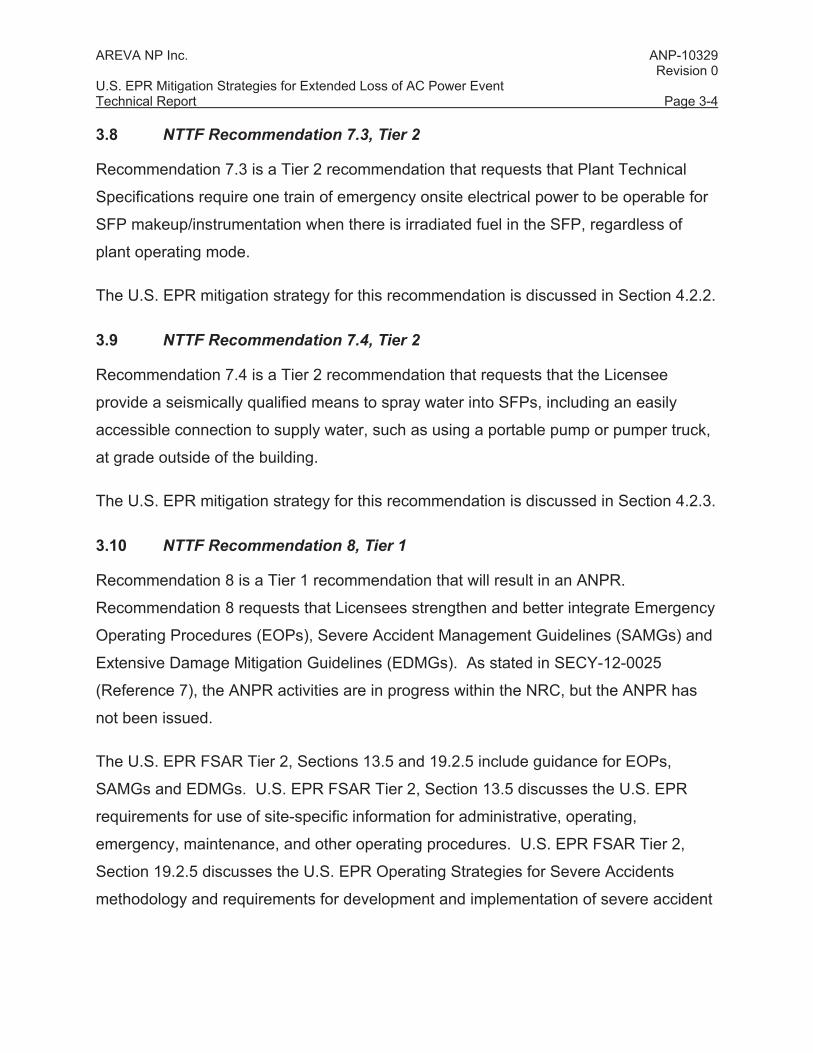
3.10 NTTF Recommendation 8, Tier 1
Recommendation 8 is a Tier 1 recommendation that will result in an ANPR.
Recommendation 8 requests that Licensees strengthen and better integrate Emergency
Operating Procedures (EOPs), Severe Accident Management Guidelines (SAMGs) and
Extensive Damage Mitigation Guidelines (EDMGs). As stated in SECY-12-0025
(Reference 7), the ANPR activities are in progress within the NRC, but the ANPR has
not been issued.
The U.S. EPR FSAR Tier 2, Sections 13.5 and 19.2.5 include guidance for EOPs,
SAMGs and EDMGs. U.S. EPR FSAR Tier 2, Section 13.5 discusses the U.S. EPR
requirements for use of site-specific information for administrative, operating,
emergency, maintenance, and other operating procedures. U.S. EPR FSAR Tier 2,
Section 19.2.5 discusses the U.S. EPR Operating Strategies for Severe Accidents
methodology and requirements for development and implementation of severe accident

AREVA NP Inc. ANP-10329 Revision 0 U.S. EPR Mitigation Strategies for Extended Loss of AC Power Event Technical Report Page 3-5
management guidelines prior to fuel loading using this methodology. No further action
on this recommendation is required for the U.S. EPR.
3.11 NTTF Recommendation 9.3, Tier 1
A portion of Recommendation 9.3 is a Tier 1 recommendation that requires Licensees
to provide enhanced emergency preparedness staffing and communications.
The U.S. EPR mitigation strategy for this recommendation is discussed in Section 4.3.
3.12 NTTF Recommendation 9.3, Tier 2
The remaining portion of Recommendation 9.3 is a Tier 2 recommendation that requires
Licensees to enhance their Emergency Plan (e.g., multiunit dose assessments, periodic
training).
U.S. EPR FSAR Tier 2, Section 13.3 discusses the U.S. EPR requirements for
development of an Emergency Plan in accordance with 10 CFR 50.47 and 10 CFR 50,
Appendix E. No further action is required on this recommendation for the U.S. EPR.

AREVA NP Inc. ANP-10329 Revision 0 U.S. EPR Mitigation Strategies for Extended Loss of AC Power Event Technical Report Page 4-1
4.0 MITIGATION ASSESSMENT
4.1 NTTF 4.2, Mitigation of Beyond Design Basis External Events
4.1.1 Overview
In NTTF Recommendation 4.2 and NRC Order EA-12-049 (Reference 1), it is
postulated that a BDBEE can deterministically result in a simultaneous ELAP and loss
of normal access to the UHS. An ELAP event assumes a simultaneous loss of AC
power (LOOP plus loss of EDGs plus loss of alternate AC source) for an indefinite
period. An evaluation of an ELAP event caused by BDBEE performed for the U.S.EPR
design. Mitigation strategies for the ELAP event have been developed based on the
guidance of NEI 12-06 (Reference 3). This FLEX guidance has been endorsed by the
NRC, with certain clarifications, provided in NRC JLD-ISG-2012-01 (Reference 11).
For new plant designs, the scope of the EA-12-049 (Reference 1) Order spans both the
Design Certification and the Combined License. Accordingly, Section 4.1 focuses on
providing a baseline coping capability with installed equipment (Phase 1), providing
permanent plant connections, and identifying performance requirements for portable
equipment to support long-term event mitigation (interface provisions for Phase 2 and 3
actions).
The scope of Section 4.1 is divided into the following subsections:
• Section 4.1.2 summarizes the acceptance criteria for core cooling, containment
integrity and spent fuel cooling.
• Section 4.1.3 describes the analytical codes and methods, key assumptions and
results of the analyses performed.
• Section 4.1.4 summarizes the reasonable protection requirements of installed
and portable equipment.

AREVA NP Inc. ANP-10329 Revision 0 U.S. EPR Mitigation Strategies for Extended Loss of AC Power Event Technical Report Page 4-2
• From the analytical bases provided in Section 4.1.3 and the reasonable
protection requirements in Section 4.1.4, the mitigation strategies for core
cooling, containment integrity and SFP cooling capabilities following an ELAP
event are provided in Section 4.1.5.
• Section 4.1.6 then summarizes the sequence of events and critical operator
actions.
• Section 4.1.7 summarizes the performance requirements for portable equipment.
4.1.2 Acceptance Criteria
The acceptance criteria for the Fukushima mitigation strategy are summarized in Table
4-1.
Table 4-1—Mitigation Strategy Acceptance Criteria
Function Acceptance Criteria
Core Cooling Fuel in core remains covered – no fuel damage Criticality – maintain core subcritical throughout the event
Spent Fuel Cooling Fuel in SFP remains covered – no fuel damage
Containment Integrity
Containment pressure remains below containment ultimate pressure capacity limits
Adequate core cooling is provided by maintaining the liquid level in the reactor vessel
above the top of the fuel in the core, and the reactor remains subcritical throughout the
event.
Adequate cooling for fuel assemblies in the SFP is provided by keeping the fuel covered
with water.

AREVA NP Inc. ANP-10329 Revision 0 U.S. EPR Mitigation Strategies for Extended Loss of AC Power Event Technical Report Page 4-3
Adequate containment integrity occurs when the containment pressure is maintained
below the Reactor Containment Building ultimate pressure capacity. As described in
U.S. EPR FSAR Tier 2, Section 3.8.1.4.11 and Table 3.8-6, the construction opening
closure is the limiting component in determining the Reactor Containment Building
ultimate pressure capacity limits. The ultimate capacity buckling pressure is 118.5 psig.
4.1.3 Analytical Bases
This section provides information about the analyses performed that provide a basis for
the ELAP event mitigation strategies, including codes and methods used, key
assumptions, and the results of the analyses.
4.1.3.1 Core Cooling in Modes 1 through 5 - Secondary Side Feed and Bleed
Analytical Methods
The analysis of the core response for an ELAP event initiated in Modes 1 through 5 was
performed using S-RELAP5. S-RELAP5 is a thermal hydraulic simulation code that
utilizes a two-fluid (plus non-condensables) model with conservation equations for
mass, energy, and momentum transfer. The reactor core is modeled with heat
generation rates determined from reactor kinetics equations (point kinetics) with
reactivity feedback, and with actinide and decay heating.
The two-fluid formulation uses a separate set of conservation equations and constitutive
relations for each phase. The effects of one phase on another are accounted for by
interfacial friction and heat and mass transfer interaction terms in the conservation
equations. The conservation equations have the same form for each phase; only the
constitutive relations and physical properties differ.
The modeling of plant components is performed by following guidelines developed to
provide accurate accounting for physical dimensions and the dominant phenomena
expected during the transient. The basic building blocks for modeling are the hydraulic
volumes for fluid paths and the heat structures for heat transfer surfaces. In addition,
special purpose components exist to represent specific components such as the pumps

AREVA NP Inc. ANP-10329 Revision 0 U.S. EPR Mitigation Strategies for Extended Loss of AC Power Event Technical Report Page 4-4
or the SG separators. Plant geometry is modeled at the resolution necessary to resolve
the flow field and the phenomena being modeled within practical computational
limitations.
Because the ELAP scenario is characterized by slow, but continuous reactor coolant
system (RCS) inventory leakage through the reactor coolant pump (RCP) seals and
core cooling occurs via natural circulation in Modes 1 through 5, the S-RELAP5 small
break loss of coolant analysis (SBLOCA) methodology was chosen to perform this
analysis. ANP-10263(P) (A), “Codes and Methods Applicability Report for the U.S.
EPR” (Reference 16), EMF-2328(P) (A), “PWR Small Break LOCA Evaluation Model, S-
RELAP5 Based” (Reference 17), and BAW-10240(P) (A), “Incorporation of M5™
Properties in Framatome ANP Approved Methods” (Reference 18) are the topical
reports that justify application of the S-RELAP5 SBLOCA methodology to the U.S. EPR.
Key Assumptions
The analysis of core cooling for ELAP events that rely on the SGs for heat removal was
performed using the following key assumptions:
• The S-RELAP5 SBLOCA model was used with the following best-estimate (or
conservative) assumptions:
- Non-safety system capabilities (such as fire water system) are included in the
model, as appropriate.
- End of cycle core reactor kinetics – conservative assumption.
- Best-estimate core decay heat.
- No stuck control rods.
- No single failures.
- No equipment out of service.

AREVA NP Inc. ANP-10329 Revision 0 U.S. EPR Mitigation Strategies for Extended Loss of AC Power Event Technical Report Page 4-5
• The ELAP event assumes a simultaneous loss of all AC power sources (LOOP,
loss of all EDGs and loss of all Alternate AC sources) in combination with a loss
of normal access to the UHS.
• The initiating ELAP event was assumed to occur when the plant is operating
normally at 100%, hot full power.
• The ELAP event causes an immediate loss of power to the RCPs and MFW
pumps, followed by a reactor trip on low RCP speed, and a turbine trip on reactor
trip.
• RCS leakage was assumed from the following two sources:
- Allowable RCS leakage per Plant Technical Specifications (11 gpm).
- RCP seal leakage. RCP seal leakage was modeled consistent with the SBO
analysis described in U.S. EPR FSAR Tier 2, Section 8.4.
• Core decay heat is removed by means of secondary side feed and bleed cooling.
This consists of depressurizing the secondary side of the SGs using the main
steam relief trains (MSRTs) and feeding the SGs using the diesel-driven fire
water pump(s).
• RCS makeup is provided passively by means of accumulator injection.
Results
For an ELAP event initiated in Modes 1 through 5, the Phase 1 mitigation strategy is to
provide natural circulation core cooling by depressurizing the SGs using the MSRTs so
that the low head, diesel-driven fire water pump(s) can supply water to the SGs via the
emergency feedwater (EFW) header. The RCP standstill seal system (SSSS) is
credited with limiting RCP seal leakage until a portable pump can be used to provide
borated RCS makeup during Phase 2. The accumulators provide an additional source
of borated RCS makeup water, but they cannot inject until the RCS pressure decreases
below the accumulator nitrogen cover gas pressure.

AREVA NP Inc. ANP-10329 Revision 0 U.S. EPR Mitigation Strategies for Extended Loss of AC Power Event Technical Report Page 4-6
A series of five S-RELAP5 cases were run to characterize the RCS response, timing of
operator actions, and latitude in potential FLEX mitigating strategies. An overview of
each case is provided as follows.
An initial case was run with no SG resupply and no SG depressurization to examine
transient phenomena timing with no operator action. SG dryout occurred at
approximately two hours after the start of the event. Core boiling began at
approximately two and a half hours, and by approximately three hours, the core liquid
level was significantly degraded.
These results indicate that the SG inventory is exhausted in about two hours if the
MSRTs remain at their normal post-trip setpoints. Once SG dryout occurs, the RCS
cannot be cooled unless the SGs are resupplied with water. Therefore, to make best
use of the available SG inventory, the SG depressurization should start as early as
possible (that is to say as soon as the plant operators recognize that they are in an
ELAP scenario).
Case 2 was run to examine the extent to which the RCS can be cooled using only the
inventory that existed in the SGs at the start of the transient. Case 2 was run with no
SG resupply and with a controlled SG depressurization of 180 °F/hr that was initiated at
1800 seconds after the start of the event.
The results indicated that SG dryout occurs at approximately one hour fifteen minutes,
and that the RCS primary can be cooled to approximately 485 °F by the controlled SG
depressurization and boil off of the residual post-trip SG inventory.
Case 3 was run to demonstrate secondary side feed and bleed when all four SGs and
MSRTs are available and the SGs are resupplied. In this case, a controlled SG
depressurization at 180 °F/hr was initiated at 1800 seconds using all four SGs. Ten
minutes after SG dryout occurred, the operators were assumed to stop the controlled
SG depressurization and quickly lower the SG pressure to 180 psia. When the SG
pressure reached the 180 psia setpoint (about 86 minutes into the event), flow from the

AREVA NP Inc. ANP-10329 Revision 0 U.S. EPR Mitigation Strategies for Extended Loss of AC Power Event Technical Report Page 4-7
diesel-driven fire pump(s) was delivered to all four SGs at a rate of 100 gpm per SG.
Accumulator injection began at about two and a half hours. SG levels began to recover
at about 3.7 hours. All core cooling acceptance criteria (refer to Section 4.1.2) were met
for this case.
Case 4 was run to demonstrate secondary side feed and bleed when only two SGs and
MSRTs are available and the SGs are resupplied. This case provides the analytical
basis for the selected mitigation strategy for an ELAP event initiated in
Modes 1 through 5. The key transient highlights for this case are as follows:
• A controlled depressurization of SGs 1 and 2 (equivalent to 90 °F/hr primary
temperature) is initiated at 1800 seconds. SG dryout occurs at approximately
4000 seconds. At 4010 seconds, the operators stop the controlled SG
depressurization and quickly lower the SG pressure to 100 psia. At 4105
seconds, the pressure in SGs 1 and 2 is �100 psia.
• At or before 4060 seconds, the operators start the diesel-driven fire water
pump(s) and deliver water to SGs 1 and 2 at a rate of 300 gpm to each SG when
SG pressure is �100 psia. During this evolution, the RCS primary is unaffected
because SG heat transfer is not interrupted.
• At approximately 8970 seconds, the RCS pressure decreases below the
accumulator pressure. Accumulator flows begin to slowly enter the cold legs to
help maintain RCS inventory and reduce the rate of RCS depressurization.
• At 10,590 seconds, SGs 1 and 2 are above 5% level which indicates that SG
inventory is being restored.
• At 14,400 seconds, flow from the diesel-driven fire water pump(s) is reduced to
150 gpm to SGs 1 and 2 since SG levels have been restored to normal.
• At 28,800 seconds, the SG flow is further reduced to 100 gpm to SGs 1 and 2.
• At 42,000 seconds, additional insurge flow from the accumulators has restored
primary inventory, refilling the RV upper head and the pressurizer surge line.

AREVA NP Inc. ANP-10329 Revision 0 U.S. EPR Mitigation Strategies for Extended Loss of AC Power Event Technical Report Page 4-8
• The S-RELAP5 run was ended at the 24-hour mark.
The results of Case 4 are depicted in Figure 4-1 through Figure 4-9. Based on these
results and the analyses performed, the following insights can be drawn:
• A coping strategy and success path exists for the ELAP event when only two
SGs and two MSRTs are available. In particular, Case 4 satisfies the core
cooling acceptance criteria given in Section 4.1.2:
- The nuclear fuel in the core remains covered with coolant water (refer to
Figure 4-7).
- No fuel damage—Fuel centerline temperatures remain safely below the
melting point, and cladding temperatures remain safely below 2200 °F.
Because the core remains covered with liquid at all times, the fuel and
cladding temperature limits are not approached and fuel damage is never at
risk.
- Criticality—Because the core is maintained subcritical throughout the event
(refer to Figure 4-8), a return to critical reactivity conditions due to overcooling
is not a concern.
• A fire water supply rate of 300 gpm per SG is adequate to initiate and maintain
natural circulation core cooling and restore SG levels. After SG levels are
restored to normal post-trip ranges, the operators would throttle fire water flow
rate to match core decay heat. Flow reductions from 300 gpm to 150 gpm per
SG at four hours, and from 150 gpm to 100 gpm per SG at eight hours were used
in the analysis.
• Based on the fire water flow rates applied in the analysis, the fire water storage
tank would need to be replenished at around 17 hours following the start of the
event.
• The pressurizer safety relief valves (PSRVs) do not lift, and the PSRVs are not
needed for RCS pressure reduction.

AREVA NP Inc. ANP-10329 Revision 0 U.S. EPR Mitigation Strategies for Extended Loss of AC Power Event Technical Report Page 4-9
• Boron precipitation is not a concern. The RCS temperature of ~350 °F is too high
for this phenomenon to be of concern.
• Pumped RCS makeup would not be required for at least 24 hours. After 24
hours, an RCS makeup pump sized for 50 gpm at 500 psi would be needed to
offset RCS leakage and/or manage core reactivity.
Figure 4-1—Case 4 Pressurizer Pressure

AREVA NP Inc. ANP-10329 Revision 0 U.S. EPR Mitigation Strategies for Extended Loss of AC Power Event Technical Report Page 4-10
Figure 4-2—Case 4 Pressurizer Level
Figure 4-3—Case 4 RC Hot Leg and RV Upper Head Temperatures

AREVA NP Inc. ANP-10329 Revision 0 U.S. EPR Mitigation Strategies for Extended Loss of AC Power Event Technical Report Page 4-11
Figure 4-4—Case 4 RC Cold Leg and RV Upper Head Temperatures

AREVA NP Inc. ANP-10329 Revision 0 U.S. EPR Mitigation Strategies for Extended Loss of AC Power Event Technical Report Page 4-12
Figure 4-5—Case 4 SG Pressures
Figure 4-6—Case 4 SG Liquid Mass

AREVA NP Inc. ANP-10329 Revision 0 U.S. EPR Mitigation Strategies for Extended Loss of AC Power Event Technical Report Page 4-13
Figure 4-7—Case 4 Core Liquid Levels
Figure 4-8—Case 4 Reactivity

AREVA NP Inc. ANP-10329 Revision 0 U.S. EPR Mitigation Strategies for Extended Loss of AC Power Event Technical Report Page 4-14
Figure 4-9—Case 4 Accumulator Liquid Levels
Case 5 was run to demonstrate secondary side feed and bleed when only two SGs and
MSRTs are available and an operational decision is made to fully open the MSRTs and
permit the SGs to blow down to near atmospheric pressure. In this case, the two
MSRTs are fully opened at 1800 seconds and the SGs are resupplied. Fire water is
delivered to the active SGs as soon as SG pressure permits (i.e., when SG pressure is
below the delivery head of the fire water pump). In this analysis, fire water flow was
initiated at the rate of 300 gpm per SG at 2340 seconds. All core cooling acceptance
criteria (refer to Section 4.1.2) were met for this case.
4.1.3.2 Core Cooling in Mode 6 and Boron Precipitation Analysis
For an ELAP event initiated in Mode 6, primary side feed and bleed cooling is used as
the method to remove core decay heat. With this core cooling method, two types of
analyses were performed:
• Core cooling analyses to determine heat removal requirements and timing
constraints for short-term accident mitigation.

AREVA NP Inc. ANP-10329 Revision 0 U.S. EPR Mitigation Strategies for Extended Loss of AC Power Event Technical Report Page 4-15
• Boron precipitation analyses to determine long-term core cooling requirements to
prevent boron precipitation.
Key Assumptions
The analysis of core cooling for an ELAP event initiated in Mode 6 was performed using
the following key assumptions:
• The initial conditions span the conditions for Modes 5 and 6; an RCS pressure
between 14.7 psia and 370 psia, and an RCS temperature � 200 ºF.
• The RCS is adequately vented to remove core decay heat in the primary feed
and bleed mode. Removal of the reactor vessel head in Mode 6 provides an
adequate vent path.
• Boiling in the core is acceptable for core cooling, provided the core remains
covered with liquid (refer to Section 4.1.2).
• Best estimate decay heat.
• The earliest time to enter Mode 5 following a normal plant shutdown is 16.67
hours. This conservative time establishes the maximum amount of core decay
heat that must be removed in Mode 6.
• RCS level was assumed to be at the reactor vessel flange.
• It was conservatively assumed that only the volumes located within the core
region are available to support the time to boil.
The analysis of boron precipitation for an ELAP event initiated in Mode 6 was performed
using the following key assumptions:
• The earliest time to enter Mode 5 following a normal plant shutdown is
approximately 16.67 hours. This conservatively establishes the maximum
amount of core decay heat that must be removed.
• RCS makeup flow in excess of boil off refills the RCS, and conservatively, only
once the cold-side is refilled, increases the mixing volume.

AREVA NP Inc. ANP-10329 Revision 0 U.S. EPR Mitigation Strategies for Extended Loss of AC Power Event Technical Report Page 4-16
• The following additional assumptions were made consistent with U.S. EPR FSAR
Tier 2, Chapter 15 LOCA boron precipitation analysis:
− The boron solubility limit is 38,500 ppm.
− The boil-off rate is based on the ANS 1973 decay heat standard with 20% uncertainty.
− There is no credit for inlet subcooling.
Results
For short-term core cooling in Mode 6, analyses and evaluations were performed to
determine injection flow requirements and estimated time to boil.
The injection flow requirements to replace boil off are determined using:
Q = W (ho – hi)
where,
Q = Decay heat.
W = Injection flow rate.
ho = Core exit enthalpy (this corresponds to the enthalpy of saturated steam
at 212 °F).
hi = Injection flow enthalpy corresponding to the injection flow temperature.
The calculated injection flow required to replace boil off at 17 hours after shutdown was
approximately 230 gpm.
The time to boil was estimated using:
Time to Saturation = (Cp) (Tsat - TInitial)/(Q)
where,
Cp = Specific heat, including credited metal mass and water volumes,
BTU/lbm°F.
Tsat = Saturation temperature at atmospheric pressure, 212 °F.

AREVA NP Inc. ANP-10329 Revision 0 U.S. EPR Mitigation Strategies for Extended Loss of AC Power Event Technical Report Page 4-17
TInitial = Initial temperature of the RCS.
Q = Best-estimate decay heat, in BTU/hr.
The estimated time to boil at 16.67 hours after shutdown with an initial temperature of
140° was 3.4 minutes (3 minutes 24 seconds).
Based on these results, the following insights can be drawn:
• A coping strategy and success path exists for the ELAP event in Mode 6 using
primary side feed and bleed cooling. In particular, the core cooling acceptance
criteria given in Section 4.1.2 can be met as follows:
- The nuclear fuel in the core remains covered with coolant.
- When RCS inventory addition is initiated, borated water is used as makeup to
maintain the core subcritical.
• RCS makeup should be restored as quickly as practicable. At a minimum, a
continuous RCS injection rate of 230 gpm is needed to maintain adequate
inventory above the top of the fuel and remove core decay heat. Borated
makeup water should be used as the injection source. The boron concentration
should be equivalent to the concentration of the IRWST to ensure long-term
subcriticality.
In Mode 6, core cooling is maintained in the long term by pumped flow from the IRWST
or from a portable source with an equivalent boron concentration. The borated water
from the IRWST provides a means for the core to remain subcritical, but causes a boron
precipitation concern because of an increase in concentration from the decay heat boil
off. An analysis was performed based on the U.S. EPR FSAR Tier 2, Chapter 15 LOCA
boron precipitation methodology to determine the minimum injection flow rate needed to
preclude boron precipitation.
The minimum flow rate to reach the solubility limit was determined. Sensitivity studies
were also performed with different flow rates and a best estimate decay heat model.
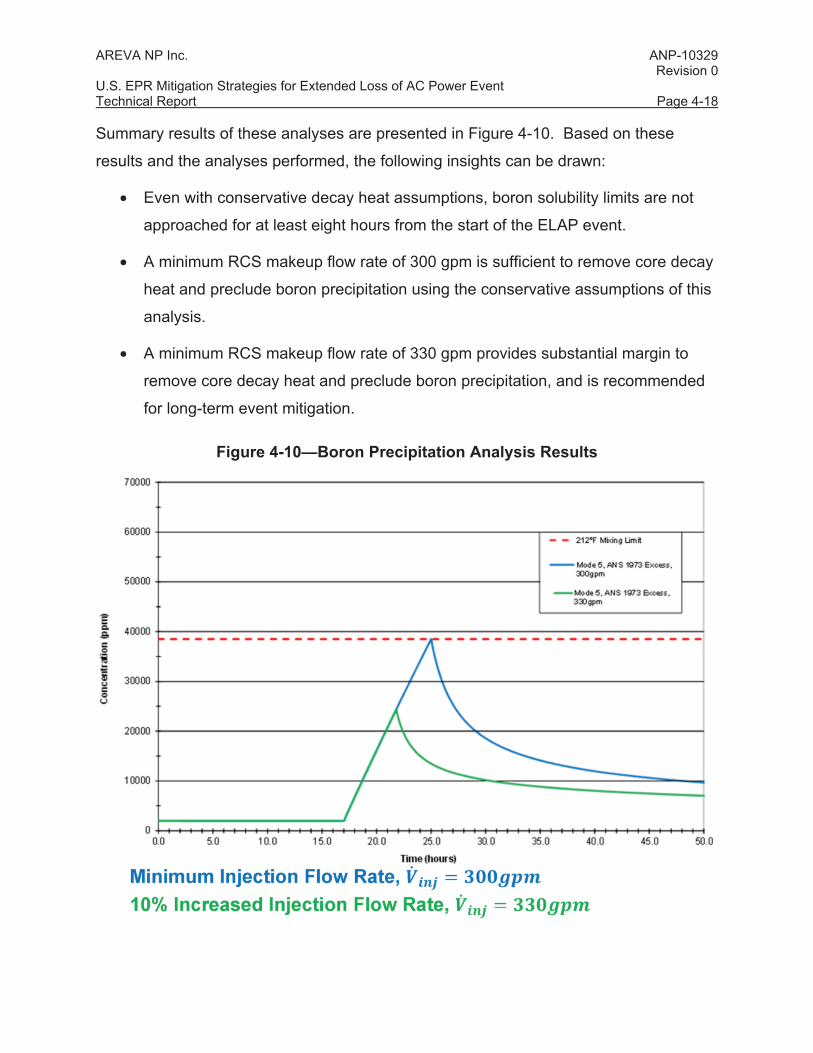
AREVA NP Inc. ANP-10329 Revision 0 U.S. EPR Mitigation Strategies for Extended Loss of AC Power Event Technical Report Page 4-18
Summary results of these analyses are presented in Figure 4-10. Based on these
results and the analyses performed, the following insights can be drawn:
• Even with conservative decay heat assumptions, boron solubility limits are not
approached for at least eight hours from the start of the ELAP event.
• A minimum RCS makeup flow rate of 300 gpm is sufficient to remove core decay
heat and preclude boron precipitation using the conservative assumptions of this
analysis.
• A minimum RCS makeup flow rate of 330 gpm provides substantial margin to
remove core decay heat and preclude boron precipitation, and is recommended
for long-term event mitigation.
Figure 4-10—Boron Precipitation Analysis Results

AREVA NP Inc. ANP-10329 Revision 0 U.S. EPR Mitigation Strategies for Extended Loss of AC Power Event Technical Report Page 4-19
4.1.3.3 RCP Seal Leakage
Following a BDBEE that results in an ELAP event, the normal methods of cooling the
RCP seals with the RCP thermal barrier coolers and RCP seal injection are lost. The
ELAP transient is similar to the SBO event that has been evaluated in U.S. EPR FSAR
Tier 2, Section 8.4. In the U.S. EPR SBO mitigation strategy, the RCP SSSS is relied
upon to close to limit RCP seal leakage. A similar strategy can be applied to the ELAP
transient provided the plant parameters are maintained within the RCP SSSS
qualification envelope.
For SBO mitigation, qualification testing was performed to demonstrate that the RCP
SSSS would limit seal leakage to less than 0.5 gpm per pump for 24 hours. During the
qualification tests, the RCP SSSS was subjected to the temperature and pressure
profile representative of an SBO event.
Based on the qualification test results, an evaluation was performed to confirm that the
SBO qualification testing envelope bounded the ELAP secondary feed and bleed
cooling transient in Modes 1 through 5 during the initial 24-hour time period. For the
Case 4 results of the S-RELAP5 analysis of secondary feed and bleed cooling (refer to
Section 4.1.3.1), the evaluation concluded that the integrity and leak rate of the RCP
SSSS is bounded by the SBO qualification tests results for the first 24 hours after loss
of seal cooling.
For long-term ELAP event mitigation (i.e., beyond 24 hours), additional loss of RCP seal
cooling tests are required for the standstill seal and the lower three RCP shaft seal
stages. Test conditions will be selected based on the following considerations:
• Test conditions bound the full range of RCS conditions (temperature and
pressure) that are expected for long-term mitigation of an ELAP event initiated in
Modes 1 through 5.
• Test conditions bound the temperature range that may cause RCP seal
degradation.

AREVA NP Inc. ANP-10329 Revision 0 U.S. EPR Mitigation Strategies for Extended Loss of AC Power Event Technical Report Page 4-20
The purpose of this qualification testing is to validate the RCP shaft seal leak rate and
integrity of the shaft seals when exposed to ELAP conditions on a long term basis.
4.1.3.4 Containment Pressure Control (Integrity)
Analytical Methods
Containment pressure control was evaluated using the GOTHIC (Generation of
Thermal-Hydraulic Information for Containments) computer code. GOTHIC is a general
purpose thermal-hydraulics software package for design, licensing, safety and operating
analysis of nuclear power plant containments and other confinement buildings.
Appropriate heat transfer and fluid flow correlations are used depending on fluid state.
Special process models are used for components such as doors, valves, heat structures
and break junctions. GOTHIC solves the conservation equations for mass, momentum
and energy for multi-component, multi-phase flow. The phase balance equations are
coupled by mechanistic models for interface mass, energy and momentum transfer that
cover the entire flow regime from bubbly flow to film/drop flow, as well as single phase
flows. The interface models allow for the possibility of thermal non-equilibrium between
phases and unequal phase velocities.
GOTHIC has previously been used to analyze the containment response as discussed
in U.S. EPR FSAR Tier 2, Section 6.2. BAW-10252PA-00, “Analysis of Containment
Response to Pipe Ruptures using GOTHIC” (Reference 19), and ANP-10299P Revision
2, “Applicability of AREVA NP Containment Response Evaluation Methodology to the
U.S. EPR™ for Large Break LOCA Analysis Technical Report” (Reference 20) are
topical reports that justify application of the GOTHIC methodology to the U.S. EPR.
Because the ELAP scenario is characterized by slow, but continuous containment
pressurization, the GOTHIC containment response methodology is an appropriate
choice for this ELAP analysis.
Key Assumptions
The GOTHIC analysis of containment response was performed using the following key
assumptions and inputs:

AREVA NP Inc. ANP-10329 Revision 0 U.S. EPR Mitigation Strategies for Extended Loss of AC Power Event Technical Report Page 4-21
• The GOTHIC subdivided multi-node EPR containment model was used as the
base model.
• ELAP events were assumed to occur in either Modes 1 through 5, or Mode 6.
Mass and energy releases from RCS leakage were modeled, along with sensible
energy from the primary side and secondary side. Mass and energy releases
from RCS leakage were based on the pertinent core cooling analysis in Modes 1
through 5 (refer to Section 4.1.3.1) or in Mode 6 (refer to Section 4.1.3.2).
Results
GOTHIC analyses were performed to determine the general timing of containment
pressurization, the limiting mode for the ELAP event accident initiation relative to
containment response, and the overall feasibility of containment spray and containment
venting options to manage containment pressure response. Based on these analyses,
the following insights can be drawn:
• For an ELAP event initiated in Modes 1 through 5, the GOTHIC analysis was run
to 24 hours with no operator action. The maximum containment pressure at 24
hours was 20.1 psia. The projected time to reach the containment ultimate
design pressure was 14.76 days (refer to Section 4.1.2).
• For an ELAP event initiated in Mode 6, the GOTHIC analysis was run to 24 hours
with no operator action. During Mode 5 primary feed and bleed (which
conservatively bounds Mode 6), a maximum containment pressure of 100.7 psia
(86 psig) was reached at 24 hours, which is safely below the containment
ultimate design pressure (refer to Section 4.1.2) of 133.2 psia (118.5 psig)
• The ELAP event initiated in Mode 6 was the limiting case because of the primary
side heat rejection via primary feed and bleed cooling into the containment. The
leakage flow rate and the leakage enthalpy are significantly higher with primary
feed and bleed than with secondary heat removal.
• The feasibility of using a containment spray strategy for Phase 2 and 3 event
mitigation was evaluated using the severe accident heat removal system

AREVA NP Inc. ANP-10329 Revision 0 U.S. EPR Mitigation Strategies for Extended Loss of AC Power Event Technical Report Page 4-22
(SAHRS) spray header. A spray flow of 88.2 lbm/sec was assumed at 24 hours.
For the limiting primary feed and bleed case, containment pressure immediately
began to decrease following spray injection, as shown in Figure 4-11.
• The feasibility of using a containment venting strategy for Phases 2 and 3 event
mitigation was also evaluated. The vent path chosen was the containment low
flow purge line through a filter bank bypass line. For the limiting primary feed
and bleed case, the low flow purge vent path was opened at five hours into the
transient at a containment pressure of 39.3 psia (24.6 psig). Containment
pressure immediately began to decrease and remained below 30 psia for the
duration of the event as shown in Figure 4-12.
• The GOTHIC containment analyses demonstrated that containment
pressurization following an ELAP event is a slow transient that provides ample
time for operator action. Containment venting or containment sprays are both
viable mitigation strategies to maintain containment integrity.

AREVA NP Inc. ANP-10329 Revision 0 U.S. EPR Mitigation Strategies for Extended Loss of AC Power Event Technical Report Page 4-23
Figure 4-11—Containment Analysis Results – Containment Spray at 24 hours

AREVA NP Inc. ANP-10329 Revision 0 U.S. EPR Mitigation Strategies for Extended Loss of AC Power Event Technical Report Page 4-24
Figure 4-12—Containment Analysis Results – Containment Venting at Less than 40 psia
4.1.3.5 Safeguard Building Heatup Analysis
Analytical Methods
The GOTHIC computer code was used to evaluate heatup of the Safeguard Buildings
(SBs) following a loss of all forced ventilation resulting from an ELAP event SB 2 was
modeled by dividing the building into 12 homogeneous temperature regions (control
volumes), which were evaluated individually with heat transfer to adjoining regions
being considered. Areas with insignificant heat loads that were not expected to
challenge equipment operability limit were grouped together into a single control volume
for model simplification. Heat loads were modeled as heaters within each control
volume.

AREVA NP Inc. ANP-10329 Revision 0 U.S. EPR Mitigation Strategies for Extended Loss of AC Power Event Technical Report Page 4-25
Key Assumptions
The GOTHIC analysis of SB 2 response was performed using the following key
assumptions and inputs:
• Room temperatures begin at the maximum normal temperature and 60%
humidity.
• Air flow between rooms is not modeled, with the exception of flow between
switchgear room 2UJK18029 and another control volume consisting of the other
switchgear room and the hall. The door to switchgear room (2UJK18029)
contains a two-foot-by-four-foot grating in it to allow airflow.
• Radiation heat transfer is neglected.
• Ambient temperature is 100 °F, consistent with Section 4.1.4.
• Five specified doors on the + 26’-7” elevation of the SB 2 are opened at 30
minutes after event initiation.
• Forced ventilation to SB 2 is restored at seven hours after event initiation.
Results
The results of the analysis indicated that all areas of SB 2 were maintained less than
130 °F. The most limiting room was the I&C cabinet room (2UJK18005), which reached
a temperature of 121 °F. After initiation of forced flow at seven hours, the temperatures
in all areas of SB 2 were maintained less than approximately 115°F.
4.1.3.6 Main Control Room Heatup Analysis
Analytical Methods
The GOTHIC computer code was used to conduct a parametric study of heatup of the
MCR following a loss of forced ventilation. Refer to Section 4.1.3.4 for a description of
the GOTHIC code. The MCR was modeled as a single node, with a single heat
structure, comprised of concrete with a painted surface. The concrete surfaces of the
room, as well as the free volume of air, served as heat sinks. The heat load was

AREVA NP Inc. ANP-10329 Revision 0 U.S. EPR Mitigation Strategies for Extended Loss of AC Power Event Technical Report Page 4-26
modeled as a heater. The parametric study examined changes in free volume, heat
source, and concrete surface area.
Key Assumptions
The GOTHIC analysis of MCR response was performed using the following key
assumptions and inputs:
• The MCR and the shift room were assumed to constitute a single, homogeneous,
free volume with concrete walls, ceiling and floor.
• The MCR was assumed to have a drop ceiling which reduced the available free
volume and concrete surface area. Additionally, the free volume of the MCR was
further reduced for conservatism.
• The thickness of the concrete walls, floor, and ceiling was conservatively
assumed to be half the thickness. The wall was conservatively treated as an
insulated boundary, which thermally isolated the MCR from the surrounding
rooms.
• The surface area of the walls, floor, and ceiling was reduced for conservatism.
• The concrete surface was assumed to be painted, with the thickness and
properties of the coating typical for painted surfaces.
• The initial room temperature was conservatively assumed to be 80 °F.
Results
The parametric study demonstrated that if ventilation or cooling is not restored to the
MCR for at least seven hours following an ELAP event, then:
• The MCR temperature would not exceed 110 °F for at least seven hours during
an ELAP event with a heat load not more than 10 BTU/sec and an initial
temperature not more than 80 °F.
• The MCR temperature would not exceed 95.1 °F if the heat load is not more than
5 BTU/sec.

AREVA NP Inc. ANP-10329 Revision 0 U.S. EPR Mitigation Strategies for Extended Loss of AC Power Event Technical Report Page 4-27
4.1.3.7 Main Control Room Portable Cooler Sizing Evaluation
Analytical Methods
An evaluation was performed to determine the total heat input to the U.S. EPR MCR
following an ELAP event to determine the minimum performance requirements for a
portable cooler (air conditioner) for the MCR. The evaluation considered the heat loads
from personnel and MCR equipment energized during an ELAP event to determine the
total MCR heat load. This total MCR heat load was then compared against the
GOTHIC parametric study results described in Section 4.1.3.6 to confirm that heatup of
the MCR was acceptable. Additionally, this total MCR heat load was used to size a
portable cooler for the MCR.
Key Assumptions • Five operators were assumed in the MCR with heat input from each operator
assumed to be 475 BTU/hr.
• Heat input to the MCR from emergency lighting is 1.5 kW.
• Heat input from the Safety Information And Control System (SICS) cabinets in
the MCR is assumed to 2.4 kW.
Results
The evaluation determined that the MCR heat input rate was 4.36 BTU/sec, or about
16,000 BTU/hr. Examination of the results of the MCR heatup parametric study
described in Section 4.1.3.6 indicated that with a heat load of 5.0 BTU/sec, the MCR
temperature will rise at most to 95.1 °F within seven hours. Based on these results, the
minimum portable cooler sizing was conservatively set at 32,000 BTU/hr (i.e., twice the
expected heat load) to provide the capability to cool down the MCR. The portable MCR
cooler would need to be placed in service within seven hours of the ELAP initiating
event.

AREVA NP Inc. ANP-10329 Revision 0 U.S. EPR Mitigation Strategies for Extended Loss of AC Power Event Technical Report Page 4-28
4.1.3.8 Spent Fuel Pool Time to Boil and Makeup Analysis
Key Assumptions
The SFP time to boil and makeup analysis was performed using the following key
assumptions and inputs:
• During an ELAP event, spent fuel cooling by the spent fuel pool cooling system
(SFPCS) heat exchangers is lost. Heatup of the SFP and boiling can be credited
to cool the spent fuel, provided the water level is maintained above the top of the
spent fuel (refer to Section 4.1.2). This spent fuel cooling strategy is consistent
with NRC Staff guidance given in Question 5.8.4 in NUREG-1628, “Staff
Responses to Frequently Asked Questions Concerning Decommissioning of
Nuclear Power Reactors” (Reference 25).
• A conservative number of rack spaces is assumed with all rack spaces filled (22
years of fuel storage).
• The maximum SFP heat load was assumed at 130 hours after reactor trip based
on a full core off-load. This SFP heat load conservatively assumes at least 15%
excess margin.
• Heat losses from the SFP are conservatively neglected.
Results
The SFP time to boil and makeup analysis was performed to determine the bulk SFP
heatup time and boil-off rate.
The SFP bulk heat-up time is conservatively calculated using Δt =MCpΔT/Q,
where,
M (lbm) is the mass of water in the SFP.
Cp (BTU/lbm°F) is the specific heat.
ΔT (°F) is the temperature rise.

AREVA NP Inc. ANP-10329 Revision 0 U.S. EPR Mitigation Strategies for Extended Loss of AC Power Event Technical Report Page 4-29
Δt (hrs) is the time to complete the temperature rise.
Q (BTU/hr) is the heat added to the SFP from the spent fuel stored in the
pool.
The boil-off rate is calculated using:
Boil off Rate = Q / hfg,
where,
Q (BTU/hr) is the heat added to the SFP from the spent fuel stored in the pool.
hfg (BTU/lbm) is the latent heat of evaporation.
Based on these analyses, the following insights can be drawn:
• During a full core offload refueling condition, the time to reach SFP bulk boiling
following the loss of all SFP cooling is approximately 4.3 hours. The initial boil-
off rate is 140 gpm. The boil-off rate decreases over time as the spent fuel decay
heat decreases.
• If spent fuel cooling is not restored, then an additional 30.5 hours is available to
boil-off the pool inventory, while maintaining the level above the top of the spent
fuel racks (refer to Section 4.1.2). Therefore, the total time to uncover the spent
fuel (from a temperature of 140 °F) is approximately 4.3 + 30.5 hours = 34.8
hours.
• Since the operators have approximately 35 hours to restore cooling and/or
makeup to the SFP, boiling of the SFP can be credited as the Phase 1 event
mitigation method, and cooling and/or makeup to the SFP can be credited for
Phases 2 and 3 event mitigation.

AREVA NP Inc. ANP-10329 Revision 0 U.S. EPR Mitigation Strategies for Extended Loss of AC Power Event Technical Report Page 4-30
4.1.3.9 DC Load Shedding
Analytical Methods
To determine how long the Class 1E uninterruptible power supply (EUPS) system
battery capacity can be extended, the following process was used:
• The loads on the EUPS battery were identified based on the design basis
accident EUPS battery sizing calculation and the Electrical Load List.
• Loads required for ELAP Phase 1 scenario mitigation were identified and their
operation defined.
• Loads to be shed from the EUPS battery for an ELAP event were identified.
• The time elapsed before ELAP load shedding takes place was identified.
• The ELAP EUPS duty cycle was defined by applying by the ELAP Phase 1
equipment operation and load shedding sequence to the loads supplied by the
EUPS battery.
• The margins to apply for the EUPS batteries during an ELAP event were
determined.
• The duration of battery discharge availability until the minimum acceptable cell
voltage is reached was determined using the EUPS battery cell type, the ELAP
EUPS duty cycle, and the ELAP margins.
Key Assumptions
The DC load shedding analysis was performed using the following key assumptions and
inputs:
• No additional accidents or failures are assumed to occur immediately prior to or
during the event, other than those causing the ELAP event.
• Reasonably protected installed electrical distribution equipment, including
inverters and cabling, is assumed to remain available.

AREVA NP Inc. ANP-10329 Revision 0 U.S. EPR Mitigation Strategies for Extended Loss of AC Power Event Technical Report Page 4-31
• ELAP event is identified at 10 minutes after initiation of the event after offsite
power is lost, all EDGs fail to start or load, and all SBO diesel generators fail to
start or load.
• DC load shedding is assumed to take 60 minutes to complete and is completed
by 70 minutes after ELAP event initiation.
• Only those containment isolation valves identified in the U.S. EPR SBO coping
strategy (refer to Section 8.4 of the U.S. EPR FSAR) and the primary coolant
injection pump containment isolation valve (30JND11AA012) are assumed to be
operated for the ELAP event.
• A minimum acceptable battery output of 210 Vdc is assumed.
• A 5% design margin is included in the cell size to account for less than optimum
operating conditions of the battery. An aging factor of 1.25 is applied to the cell
capacity to provide reasonable assurance that the battery is capable of meeting
its design loads throughout its service life. A temperature correction factor of
1.11 (60 °F) is applied to the cell capacity.
Results
Based on this analysis, it was determined that the EUPS battery discharge duration can
be extended from two hours to eight hours and 30 minutes. The overall timeline for DC
load shedding is provided in Figure 4-13. To extend the EUPS battery capacity to this
duration, the following operator actions are required:
• Identify the ELAP event and begin DC load shedding in all four divisions of the
EUPS within 10 minutes after initiation of the ELAP event.
• Complete shedding of non-ELAP loads in all four divisions of the EUPS within 70
minutes after initiation of the ELAP event.

AREVA NP Inc. ANP-10329 Revision 0 U.S. EPR Mitigation Strategies for Extended Loss of AC Power Event Technical Report Page 4-32
• Before the EUPS divisions are depleted at eight hours and 30 minutes, re-
energize credited EUPS Divisions 1 and 2 for long-term event mitigation in
Phases 2 and 3.
Figure 4-13—ELAP Battery Discharge Duration
4.1.4 Reasonable Protection of Installed and Portable Equipment
The term “reasonable protection,” within the context of this technical report, means that
the design of the SSC it is describing either meets the U.S. EPR design basis for the
applicable external hazards, or has been shown by analysis or test to meet or exceed
the U.S. EPR design basis. This definition is consistent with the definition of “robust” in
NEI 12-06 (Reference 3).
Additionally, NEI 12-06 (Reference 3) provides the following guidance:
Section 3.2 Performance Attributes states:
“…installed equipment that is designed to be robust with respect to DBEE
is assumed to be fully available”.

AREVA NP Inc. ANP-10329 Revision 0 U.S. EPR Mitigation Strategies for Extended Loss of AC Power Event Technical Report Page 4-33
Section 3.2.1.3 Initial Conditions, (6) states:
“Permanent plant equipment that is contained in structures with designs
that are robust with respect to seismic events, floods and high winds and
associated missiles are available.”
Section 3.2.1.3 (8) states:
“Installed electrical distribution systems…remain available provided they
are protected…”
The non-safety-related SSC (for example, diesel-driven fire water pump, discharge
piping, portable equipment, Fire Protection Building, and the fire water storage tanks)
that are relied upon to mitigate an ELAP event are designed to meet the FLEX
reasonable protection standards. The following subsections comprise a list of external
hazards defined in Section 2 of NEI 12-06 (Reference 3) and a description of the way in
which the non-safety-related SSC, including the FLEX equipment, portable equipment,
and Fire Protection Building, meet the FLEX reasonable protection requirements.
NEI 12-06 (Reference 3) provides the following guidance:
Section 2.3 states:
“Considering the external hazards applicable to the site, the FLEX
mitigation equipment should be stored in a location or locations such that
it is reasonably protected such that no one external event can reasonably
fail the site FLEX capability. Reasonable protection can be provided for
example, through provision of multiple sets of portable on-site equipment
stored in diverse locations or through storage in structures designed to
reasonably protect from applicable external events.”

AREVA NP Inc. ANP-10329 Revision 0 U.S. EPR Mitigation Strategies for Extended Loss of AC Power Event Technical Report Page 4-34
Seismic
The Fire Protection Building and the fire water storage tanks are the only non-safety-
related structures that are credited for Phase 1 event mitigation of an ELAP event. The
Fire Protection Building and the fire water storage tanks are designed to meet or exceed
ASCE 7-10, “Minimum Design Loads for Buildings and Other Structures” (Reference
22), consistent with the FLEX guidance.
Equipment that is credited for Fukushima event mitigation is either Seismic Category I,
or is non-safety-related equipment that is installed in Seismic Category I, Seismic
Category II and Conventional Seismic structures with the following clarification:
To provide adequate functionality following a safe shutdown earthquake (SSE), the
following supplemental seismic requirements are imposed:
• For valves and piping – ANSI/ASME B31.1 (Reference 24). For example, this
includes the non-safety-related piping and valves from the diesel-driven fire water
pumps to the Emergency Feedwater system.
• For other SSC – ASCE 43-05, “Seismic Design Criteria for Structures, Systems,
and Components in Nuclear Facilities” (Reference 23). For example, this
includes the ELAP diesel generator.
This seismic qualification strategy for equipment is consistent with the seismic
qualification strategy used for the non-safety-related Fire Protection System as
described in U.S. EPR FSAR Tier 2, Section 9.5.1.
Flooding
The U.S. EPR is designed as a “dry site” location, which means the plant grade level is
located one foot above the flood elevation. This refers to the Seismic Category I safety-
related structures. The Fire Protection Building and the fire water storage tanks are the
only non-safety-related structures that are credited for Phase 1 event mitigation of an
ELAP event. Taking this into account, the Fire Protection Building and the fire water
storage tanks are designed and constructed at least one foot above the flood elevation.

AREVA NP Inc. ANP-10329 Revision 0 U.S. EPR Mitigation Strategies for Extended Loss of AC Power Event Technical Report Page 4-35
Severe Storms with High Winds / Missile Protection
The Fire Protection Building and fire water storage tanks are designed to meet or
exceed ASCE 7-10 (Reference 22). In accordance with NEI 12-06 FLEX requirements,
the Fire Protection Building and the fire water storage tanks are missile protected.
Missile protection of the Fire Protection Building and fire water storage tanks is provided
for a hurricane wind speed of 230 mph per Regulatory Guide 1.221 (Reference 19).
Selection of this hurricane wind speed is consistent with U.S. EPR FSAR Tier 2, Section
3.3.2.1.
Snow, Ice, and Extreme Cold
The Fire Protection Building and fire water storage tanks are designed to meet or
exceed ASCE 7-10 (Reference 22), consistent with the FLEX guidance. Minimum
temperatures for design of non-safety systems in the U.S. EPR are based on a best-
estimate, 1% exceedance value of -10 °F. Because of the beyond design basis nature
of the ELAP event, design evaluations of equipment performance (safety-related or non-
safety-related) are similarly based on a best-estimate, 1% exceedance value of -10 °F.
High Temperatures
In accordance with NEI 12-06 (Reference 11), equipment should be maintained at a
temperature within a range to support its likely function when called upon. Maximum
temperatures for design of non-safety systems are based on a best-estimate, 1%
exceedance value of 100 °F dry bulb / 77 °F wet bulb coincident. Because of the
beyond design basis nature of the ELAP event, design evaluations of equipment
performance (safety-related or non-safety-related) are similarly based on a
best-estimate, 1% exceedance value of 100 °F dry bulb / 77 °F wet bulb coincident.
Table 4-2 provides a summary of reasonable protection.

AREVA NP Inc. ANP-10329 Revision 0 U.S. EPR Mitigation Strategies for Extended Loss of AC Power Event Technical Report Page 4-36
Table 4-2—Reasonable Protection of ELAP Event Mitigation Equipment
Hazard Applicability General Approach Seismic Structure Seismic Category I or ASCE 7-10 for Seismic
Category II and Conventional Seismic structures.
Systems and Components
Seismic Category I or reasonable protection of non-safety-related installed equipment in Seismic Category I, Seismic Category II and Conventional Seismic structures. Reasonable protection of non-safety-related equipment installed in Seismic Category I, Seismic Category II and Conventional Seismic structures includes: • ASME B31.1 – piping, valves and supports. • ASCE 43-05 – other equipment (e.g.,
pumps, diesels, electrical). Flooding Structure Seismic Category I or Seismic Category II and
Conventional Seismic structures located at same elevation as Seismic Category I structures. Note: U.S. EPR uses a “dry site” concept for Seismic Category I structures.
High Wind Structure Seismic Category I or ASCE 7-10 for Seismic Category II and Conventional Seismic structures with wind speeds based on Regulatory Guide 1.221.
Snow, Ice and Cold Temperatures
Structure Seismic Category I or ASCE 7-10 for Seismic Category II and Conventional Seismic structures.
Systems and Components
Equipment (safety-related or non-safety-related) evaluated for 1% exceedance temperatures (-10 °F).
High Temperatures
Structure Seismic Category I or ASCE 7-10 for Seismic Category II and Conventional Seismic structures.
Systems and Components
Equipment (safety-related or non-safety-related) evaluated for 1% exceedance temperatures (100 °F dry bulb/77 °F wet bulb coincident).

AREVA NP Inc. ANP-10329 Revision 0 U.S. EPR Mitigation Strategies for Extended Loss of AC Power Event Technical Report Page 4-37
4.1.5 Mitigation Strategies
Based on the analytical bases provided in Section 4.1.3 and the reasonable protection
requirements provided in Section 4.1.4, mitigation strategies were developed to satisfy
the overall acceptance criteria given in Section 4.1.2. In particular, mitigation strategies
were grouped as follows:
• AC and DC Power (Section 4.1.5.1).
• Core Cooling in Modes 1 through 5 (Secondary Side Feed and Bleed) (Section
4.1.5.2).
• Core Cooling in Mode 6 with the Reactor Vessel Head Removed (Section
4.1.5.3).
• Containment Pressure Control (Integrity) (Section 4.1.5.4).
• Spent Fuel Cooling (Section 4.1.5.5).
• Instrumentation and Controls (Section 4.1.5.6).
• Support Functions (Section 4.1.5.7).
Details of the mitigation strategy for each of these groupings are provided in the
following subsections.
4.1.5.1 AC and DC Power
During an ELAP event, DC power is required for operation of electrical switchgear and
I&C systems and for operation of essential AC motor-operated valves that are battery
backed. The only power sources available during Phase 1 event mitigation are the
two-hour batteries and their associated EUPS busses. Actions are required to extend
the period of time that this power is available.
In the U.S. EPR EUPS design, each of the 250 VDC two-hour batteries
(31/32/33/34BTD01) is connected to a 250 VDC switchboard (31/32/33/34BUC). One
of two redundant battery chargers (31/32/33/34BTP01 or 31/32/33/34BTP02) is

AREVA NP Inc. ANP-10329 Revision 0 U.S. EPR Mitigation Strategies for Extended Loss of AC Power Event Technical Report Page 4-38
connected to each 250 VDC switchboard. The EUPS battery chargers BTP01 and
BTP02 are normally supplied 480 VAC input power by the emergency power supply
system (EPSS). Battery charger BTP01 is supplied by EPSS load center BMC in
Divisions 1 and 4 and by EPSS motor control center (MCC) BNA02 in Divisions 2 and 3.
Battery charger BTP02 is supplied by EPSS load center BMB in all four divisions. The
battery chargers rectify the 480 VAC power to 250 VDC power and furnish electrical
energy for the steady-state operation of loads connected to 250 VDC switchboards,
while returning its battery to a full state of charge or maintaining its battery in a fully
charged state.
Each 250 VDC switchboard provides input power to an inverter. The inverter is used to
transform the DC power to three phase AC power to the EUPS busses.
For the mitigation of an ELAP event, all non-essential loads with the exception of the
I&C cabinets are segregated from essential loads on separate AC and DC busses,
referred to as “load shed busses.” Refer to U.S. EPR FSAR Tier 2, Figure 8.3-5. Each
load shed bus is connected to the associated EUPS bus or 250 VDC switchboard by an
isolation device that can be remotely operated from the Main Control Room (MCR). An
ELAP condition is identified shortly after it has been determined that the EPSS buses
cannot be energized from the EDGs or the SBO diesel generators. All load shed bus
infeed isolation devices are opened from the MCR within 60 minutes after determination
that an ELAP is in progress to conserve the stored energy in the batteries. Nine SAS
cabinets in Divisions 1 and 4, six safety automation system (SAS) cabinets in Divisions
2 and 3, and one SICS remote shutdown station (RSS) workstation cabinet in Divisions
1 and 4 are de-energized locally by opening isolation devices at the cabinets. These
actions extend battery availability to eight hours and 30 minutes as discussed in Section
4.1.3.9.
Prior to depletion of the batteries, the batteries in Divisions 1 and 2 are recharged from
a prestaged, permanently installed dedicated diesel generator using the Divisions 1 and
2 battery chargers. The diesel generator is located in the Fire Protection Building and is

AREVA NP Inc. ANP-10329 Revision 0 U.S. EPR Mitigation Strategies for Extended Loss of AC Power Event Technical Report Page 4-39
referred to as the ELAP diesel generator. The ELAP diesel generator is independent
from the plant and is also used to power permanently-installed plant equipment that is
credited for Phase 2 and 3 event mitigation (for example, the primary coolant injection
pump). This ELAP diesel generator is provided with a diesel fuel storage tank with a
minimum capacity corresponding to eight hours of fully loaded operation. The ELAP
diesel fuel storage tank is provided with external fill connections to allow replenishment
in Phases 2 and 3. The ELAP diesel generator has a minimum load capability of 650
kw.
The ELAP diesel generator is a 480 VAC generator with a transformer to step up the
voltage to 6.9 kV. The power is transmitted from the Fire Protection Building to the SB
at 6.9 kV, and stepped down to 480V using a 6.9 kV to 480V step-down transformer.
The 6.9 kV to 480V step-down transformer is located in SB 2 to meet FLEX reasonable
protection requirements.
The feed from the ELAP diesel generator is routed to two transfer switches. Refer to
Figure 4-14. One switch is located in the Division 1 feed from 6.9 kV switchgear 31BDB
to EPSS 480V load center 31BMB, and the other is located in the Division 2 feed from
6.9 kV switchgear 32BDB to EPSS 480V load center 32BMB. The transfer switches are
located in SBs 1 and 2, which meet the FLEX reasonable protection requirements.
Two additional transfer switches are provided that allow connection of 480V portable
generators, which are provided by the COL applicant. One of the transfer switches is
capable of providing power from either the ELAP diesel generator or a portable
generator to the transfer switches feeding both 31BMB and 32BMB. The other transfer
switch is only capable of providing power from either the ELAP DG or a portable
generator to the transfer switch feeding 32BMB. Temporary connections to each of
these transfer switches is provided from easily accessible electrical connections located
at grade level inside the SBs. The transfer switches are arranged to allow the portable
diesel generator at each connection to feed one EPSS 480V load center, or a larger
portable generator connected to the transfer switch capable of providing power to both

AREVA NP Inc. ANP-10329 Revision 0 U.S. EPR Mitigation Strategies for Extended Loss of AC Power Event Technical Report Page 4-40
31BMB and 32BMB to feed both EPSS 480V load centers. This provides the COL
applicant the option of providing one larger, or two smaller portable diesel generators.
This AC and DC repowering mitigation strategy reflects the following considerations:
• At least two 250 VDC switchboards (Divisions 1 and 2) and their associated
EUPS busses must be powered from the ELAP diesel generator because all
systems are not four-division or four-train redundant, and certain equipment
requires power from a minimum of two EUPS divisions to be operable. The main
steam relief isolation valves (MSRIVs) require two EUPS divisions to be
operable. The communications equipment and special emergency lighting is not
four-division or four-train redundant either.
• The Division 3 and Division 4 250 VDC switchboards and their associated EUPS
busses are de-energized by eight hours and 30 minutes after initiation of the
event prior to depletion of their associated batteries. All loads are stripped from
the Division 3 and Division 4 250 VDC switchboards and EUPS busses, and then
the associated battery isolation device is opened. These actions are performed
for equipment protection of the batteries, and are not required for event
mitigation.
• The plant operators have ample time (eight hours and 30 minutes after initiation
of the event) to repower the EUPS Divisions 1 and 2. As a result, the ELAP
event can be mitigated in the short term (Phase 1) and long term (Phases 2 and
3) using only Division 1 and 2 equipment without power interruption.
The sequence of actions and required completion times for re-energizing Divisions 1
and 2 differ depending upon the plant mode at event initiation.
Modes 1 through 5
If the ELAP event is initiated in Modes 1 through 5, action is required to place the ELAP
diesel generator in service within seven hours after event initiation to allow operation of
Division 1 and Division 2 supply and exhaust ventilation fans of the electrical division of

AREVA NP Inc. ANP-10329 Revision 0 U.S. EPR Mitigation Strategies for Extended Loss of AC Power Event Technical Report Page 4-41
the safeguard building ventilation system (SBVSE). All loads are stripped from EPSS
480V load centers 31BMB and 32BMB and the four transfer switches are aligned to
supply power from the ELAP diesel generator to the 480V load centers. The ELAP
diesel generator is then started and its output breaker is closed, energizing 31BMB and
32BMB. All loads are stripped from 480V MCC 31BNB01 and 32BNB01, and the MCCs
are energized by closing the feeder breakers from EPSS 480V load center 31BMB and
32BMB. The load breakers on 31BNB01 and 32BNB01 for the SBVSE Trains 1 and 2
supply, exhaust, and battery room fans are then closed.
The breakers on EPSS 480V load center 31BMB for battery charger 31BTP02 and on
480V load center 32BMB for battery charger 32BTP02 are closed prior to depletion of
the Division 1 and Division 2 batteries at eight hours and 30 minutes after event
initiation.
Mode 6 with the Reactor Vessel Head Removed
If the ELAP event is initiated in Mode 6 with the reactor vessel head removed,
repowering of Divisions 1 and 2 is performed in three phases to minimize the time
required to place the primary coolant injection pump in service.
In the first phase, the primary coolant injection pump is required to be placed in service
within two hours after event initiation, prior to exhaustion of the accumulator inventory
(refer to Section 4.1.3.2). For this phase, only 31BMB and 31BNB01 are re-energized
to provide power to the pump. In the second phase, 32BMB and 32BNB01 are
energized to allow operation of Division 2 SBVSE supply and exhaust ventilation fans.
In the third phase the Divisions 1 and 2 EUPS 250 VDC switchboards and busses are
powered from the ELAP diesel generator.
To implement the first phase, two transfer switches are positioned to align the output of
the ELAP diesel generator to EPSS 480V load center 31BMB. All loads are stripped
from EPSS 480V load center 31BMB and 480V MCC 31BNB01. The ELAP diesel
generator is started and its output breaker is closed, restoring electrical power to EPSS

AREVA NP Inc. ANP-10329 Revision 0 U.S. EPR Mitigation Strategies for Extended Loss of AC Power Event Technical Report Page 4-42
480V load center 31BMB. EPSS 480V MCC 31BNB01 is energized by closing its
feeder breaker from EPSS 480V load center 31BMB.
In the second phase, action is required to power EPSS 480V MCC 32BNB01 to allow
operation of Division 2 SBVSE supply and exhaust ventilation fans within seven hours
after event initiation. All loads are stripped from EPSS 480V load center 32BMB and
480V MCC 32BNB01. Two transfer switches are positioned to align the output of the
ELAP diesel generator to EPSS 480V load center 32BMB. EPSS 480V MCC 32BNB01
is energized by closing the feeder breaker on EPSS 480V load center 32BMB. EPSS
480V MCC 31BNB01, which supplies the SBVSE Train 1 fans, was energized in the first
phase. The load breakers on 31BNB01 and 32BNB01 for the SBVSE Trains 1 and 2
supply, exhaust, and battery room fans are then closed.
In the third phase, action is required to power the Division 1 and Division 2 250 VDC
switchboards and EUPS busses from the ELAP diesel generator prior to depletion of the
Division 1 and Division 2 batteries. To accomplish this, the breakers on EPSS 480V
load center 31BMB for battery charger 31BTP02 and on 480V load center 32BMB for
battery charger 32BTP02 are closed prior to eight hours and 30 minutes after event
initiation.

AREVA NP Inc. ANP-10329 Revision 0 U.S. EPR Mitigation Strategies for Extended Loss of AC Power Event Technical Report Page 4-43
Figure 4-14—Simplified Diagram of Repowering EUPS
4.1.5.2 Core Cooling in Modes 1 through 5 (Secondary Side Feed and Bleed)
Three main functional objectives must be satisfied to effectively provide core cooling in
Modes 1 through 4 using secondary side feed and bleed:
• RCS inventory control.
• Primary heat removal.
• Reactivity control.
The U.S. EPR strategy is to utilize secondary feed and bleed cooling when the RCS is
intact and the SGs are available. If the ELAP event occurs in Mode 5 and the SGs are
available for use, the RCS is allowed to heat up into Mode 4 and secondary side feed
and bleed cooling will be used for core cooling.

AREVA NP Inc. ANP-10329 Revision 0 U.S. EPR Mitigation Strategies for Extended Loss of AC Power Event Technical Report Page 4-44
For primary heat removal, Table D-1 of NEI 12-06 provides a summary of performance
attributes for PWR core cooling functions. For core cooling and heat removal in Modes
5 and 6 with SGs not available, it establishes the following method:
“All Plants Provide Means to Provide Borated RCS Makeup**
** Note: There may be short periods of time during Modes 5 & 6 where plant
configuration may preclude use of this strategy.”
For the U.S. EPR, a condition exists during short periods of Mode 5 operation where the
plant configuration precludes using borated RCS makeup to provide core cooling.
During the transition to and from Mode 6, a condition exists when the SGs are not
available for heat removal and the reator vessel head is not removed. If the reactor
vessel head is not removed, there is insufficient venting of the RCS to support primary
feed and bleed cooling. The duration of this condition is limited in nature (e.g., two to
three days of total time each fuel cycle).
The risk associated with operating in this condition, following a BDBEE is low because:
• The exposure time period is short.
• The frequency of a BDBEE occurring during such a short exposure time period is
very low, particularly a BDBEE of sufficient magnitude to result in a LOOP,
common cause failure of the EDGs and common cause failure of the SBO diesel
generators.
An assessment of the plant risk during these BDBEE conditions is described in U.S.
EPR FSAR Tier 2, Section 19.1.5.4.
An overview of the mitigation strategies for these functional objectives is provided in
Table 4-3. Details of the mitigation strategies for each of these functional objectives are
provided in the following subsections.

AR
EV
A N
P In
c.
A
NP
-103
29
Rev
isio
n 0
U.S
. EP
R M
itiga
tion
Stra
tegi
es fo
r Ext
ende
d Lo
ss o
f AC
Pow
er E
vent
Te
chni
cal R
epor
t
Pag
e 4-
45
Tabl
e 4-
3—FL
EX C
apab
ility
– C
ore
Coo
ling
Sum
mar
y –
Mod
es 1
thro
ugh
5
Safe
ty F
unct
ion
Met
hod
Phas
e 1
Phas
e 2
and
3
Core Cooling
Rea
ctor
Cor
e C
oolin
g an
d H
eat
Rem
oval
(M
odes
1
thro
ugh
5 S
Gs
avai
labl
e)
• S
econ
dary
sid
e fe
ed
and
blee
d w
ith
dies
el-d
riven
fire
pum
p to
feed
SG
s vi
a E
FW
head
er.
• D
epre
ssur
ize
SG
s fo
r se
cond
ary
mak
eup.
•
Sus
tain
ed s
ourc
e of
m
akeu
p w
ater
.
• P
erm
anen
t pip
ing
from
sei
smic
ally
qu
alifi
ed d
iese
l-driv
en fi
re p
ump
to
EFW
hea
der.
• S
Gs
are
depr
essu
rized
usi
ng
MS
RTs
. •
SG
mak
eup
suffi
cien
t to
rest
ore
SG
le
vel w
ith in
stal
led
equi
pmen
t fo
llow
ing
SG
dry
out.
• Fi
re w
ater
sto
rage
tank
s an
d bu
ildin
g ar
e re
ason
ably
pro
tect
ed.
• P
erm
anen
t con
nect
ions
(prim
ary
and
alte
rnat
e) fo
r por
tabl
e, s
elf-
pow
ered
, SG
mak
eup
pum
p.
• P
orta
ble
mea
ns to
refil
l fire
wat
er
stor
age
tank
to e
xten
d ba
selin
e co
ping
. •
Por
tabl
e m
eans
to re
fill f
ire p
ump
dies
el ta
nks
and
lube
oil
to e
xten
d ba
selin
e co
ping
.
RC
S In
vent
ory
Con
trol/L
ong-
Te
rm
Sub
criti
calit
y
• Lo
w le
akag
e R
CP
se
als
and/
or b
orat
ed
high
pre
ssur
e R
CS
m
akeu
p re
quire
d.
• R
CP
SS
SS
lim
its R
CP
sea
l lea
kage
du
ring
initi
al e
vent
miti
gatio
n.
• A
ccum
ulat
or v
olum
e in
itial
ly
mai
ntai
ns R
CS
inve
ntor
y an
d bo
rate
s th
e R
CS
.
• P
erm
anen
t con
nect
ions
(prim
ary
and
alte
rnat
e) fo
r por
tabl
e, s
elf-
pow
ered
, hig
h pr
essu
re R
CS
m
akeu
p pu
mp.
•
Bor
ated
wat
er s
ourc
e is
por
tabl
e ta
nk m
ixed
on
site
, off-
site
sou
rce,
IR
WS
T, o
r ext
ra b
orat
ing
syst
em
(EB
S) t
anks
. K
ey R
eact
or
Par
amet
ers
• S
G le
vel.
• S
G p
ress
ure.
•
RC
S p
ress
ure.
•
RC
S te
mpe
ratu
re.
• In
stru
men
ts p
ower
ed b
y C
lass
1E
D
C b
us.
• D
C lo
ad s
hedd
ing
used
to e
xten
d ba
selin
e co
ping
.
• P
ower
Div
isio
ns 1
and
2 C
lass
1E
ba
tterie
s us
ing
eith
er th
e E
LAP
di
esel
gen
erat
or in
the
Fire
P
rote
ctio
n B
uild
ing
or b
y po
rtabl
e ge
nera
tors
.

AREVA NP Inc. ANP-10329 Revision 0 U.S. EPR Mitigation Strategies for Extended Loss of AC Power Event Technical Report Page 4-46
4.1.5.2.1 RCS Inventory Control
Adequate core cooling is provided by maintaining the liquid level in the reactor vessel
above the top of the fuel in the core (refer to Section 4.1.2). RCS inventory control is
challenged during an ELAP event by the loss of all AC powered RCS injection sources
and by the potential for increased RCP seal leakage resulting from overheating of the
RCP seals. Mitigation of the challenge to core cooling requires a source of makeup to
the RCS, as well as minimization of RCS inventory losses.
4.1.5.2.1.1 RCS Makeup
The reduction in RCS pressure resulting from primary to secondary heat transfer during
SG depressurization enables the accumulators to inject borated water for RCS
inventory makeup and reactivity control. Approximately 37,000 gallons of accumulator
inventory is available to make up for RCS contraction and leakage until pumped
injection can be placed into service.
In Section 4.1.3.1, analyses were performed to characterize the RCS response to an
ELAP event initiated in Modes 1 through 5. These results indicated that accumulator
injection began at approximately two and a half hours into the event and continued until
approximately 24 hours without exhausting the accumulator inventory. These results
indicate that adequate time exists for installation and alignment of a source of pumped
injection for RCS makeup in Phase 2 (refer to simplified Figure 4-15).
An alternate supply source can be connected to the EBS discharge piping using a
portable pump. The suction source to the portable pump may be a portable borated
water supply or the IRWST. The U.S. EPR uses enriched boron. The equivalent boron
concentration of the portable borated water supply is in the range of 1700 ppm enriched
boron to 1900 ppm enriched boron. These values correspond to the minimum and
maximum Technical Specification limits for the IRWST and accumulators.

AREVA NP Inc. ANP-10329 Revision 0 U.S. EPR Mitigation Strategies for Extended Loss of AC Power Event Technical Report Page 4-47
Figure 4-15—RCS Makeup in Modes 1 through 5 Simplified Diagram
Two connections are provided on the EBS discharge lines to allow installation of a
portable self-powered RCS makeup pump for Phase 2 event mitigation. The connection
points are two EBS vent lines (valves 30JDH10AA506 and 30JDH40AA506). The two
valves satisfy the FLEX N+1 criterion because the Fuel Building (FB) is protected, and
the two valves are located in different zones of the FB. Refer to U.S. EPR FSAR Tier 2,
Figure 6.8-1.
The core cooling analysis described in Section 4.1.3.1 indicated that the RCS pressure
at the time pumped makeup would be required was approximately 400 psia. RCS
leakage at this time was assumed to be 13 gpm. A calculation was performed to
establish the minimum pump performance required. The results of this calculation show
that the pump must be able to provide 50 gpm (to provide margin for possible increased
RCS leakage) with a head rise across the pump of 1242 ft. The required net positive
suction head (NPSH) for the pump must be less than 23.79 ft. The maximum expected

AREVA NP Inc. ANP-10329 Revision 0 U.S. EPR Mitigation Strategies for Extended Loss of AC Power Event Technical Report Page 4-48
pump discharge pressure under these conditions was calculated to be 548.4 psia. The
EBS vent valve lines used as connection points are sized at two inches to
accommodate the 50 gpm makeup flow rate.
If EBS Division 1 is used, the portable pump is connected to 30JDH10AA506. EBS
Train 1 containment isolation valve (30JDH10AA006) is opened, and either EBS Train 1
RCS isolation valve (30JDH10AA015) or EBS Train 2 RCS isolation valve
(30JDH20AA015) is opened to provide a flow path to the RCS. All of the valves required
to be aligned to provide a flow path to the RCS are powered from their respective
divisional EUPS busses.
Operators open EBS Division 4 containment isolation valve (30JDH40AA006) and either
EBS Division 3 RCS isolation valve (30JDH30AA015) or EBS Train 4 RCS isolation
valve (30JDH40AA015) from the MCR prior to Division 3 and Division 4 battery
depletion at eight hours and 30 minutes. All of the valves are powered from their
respective divisional EUPS busses. This action is performed even if the plan is to use
EBS Division 1, because Division 3 and Division 4 EBS RCS isolation valves are
located inside the containment and must be opened to create a viable RCS makeup
path from EBS Division 4 to maintain N+1 capability. If EBS Division 4 is used, the
portable pump is connected to 30JDH40AA506, and the EBS Division 4 containment
isolation valve (30JDH40AA006) and either EBS Division 3 RCS isolation valve
(30JDH30AA015) or EBS Division 4 RCS isolation valve (30JDH40AA015) provide a
flow path to the RCS.
4.1.5.2.1.2 Minimizing RCS Inventory Losses
Following an ELAP event initiated in Modes 1 through 4, RCS inventory loss can occur
through three pathways:
• RCS letdown.
• Pressurizer continuous degasification line.
• RCP seals.
AREVA NP Inc. ANP-10329 Revision 0 U.S. EPR Mitigation Strategies for Extended Loss of AC Power Event Technical Report Page 4-49
The letdown line isolation valve (30KBA10AA001) is automatically closed upon
detection of low EDG bus voltage in all four electrical divisions for greater than 30
seconds. The letdown line isolation valve is powered from the Division 1 EUPS
(31BRA) and fails as-is upon a loss of power after isolation.
The flow through the pressurizer continuous degasification line is limited by a flow
restriction to approximately 0.004 lbm/sec. The pressurizer continuous degasification
isolation valves (30JEF10AA503 and 30JEF10AA504) are closed by the operator when
time is available. The pressurizer continuous degasification isolation valves are
powered from the Division 1 and Division 4 EUPS busses (31BRA and 34BRA) and fail
as-is upon a loss of power after isolation.
The RCPs are provided with an SSSS to limit RCP seal leakage during loss of seal
cooling events (refer to Figure 4-16). The SSSS is a static seal located above the
Number 3 seal, between the Number 3 seal housing and the pump coupling sleeve. It
consists of a ring piston surrounding the pump shaft, which moves up under nitrogen
pressure to land on the counter-ring of the shaft (closing annular space “E” in Figure
4-16). When the static seal is open, the piston is located on the bottom side of the
Number 3 seal housing. To engage the SSSS, the piston is raised by injecting nitrogen
under the piston until it comes into contact with the counter-ring. The leak tightness is
created by metal to metal contact. The static seal is equipped with springs between the
top of the piston and the end of the static seal housing. These springs are designed to
return the piston to the down position when there is no actuation pressure and no
pressure downstream of the Number 3 seal. Static sealing between the components
(for example, piston and housing) is provided by O-rings designed for high
temperatures.
The operators will remotely close the SSSS and all three seal leak-off isolation valves
on each RCP within 15 minutes after the RCPs have tripped. All of the valves required
to change position for SSSS closure and seal return isolation are powered from the
EUPS two-hour batteries and fail as-is upon a loss of power after actuation. Closure of

AREVA NP Inc. ANP-10329 Revision 0 U.S. EPR Mitigation Strategies for Extended Loss of AC Power Event Technical Report Page 4-50
the SSSS and seal return isolation valves on all four RCPs limits total RCP seal leakage
to less than or equal to 2 gpm.
Figure 4-16—RCP SSSS
4.1.5.2.2 Primary Heat Removal
Primary heat removal is required to remove the decay heat transferred from the core to
the RCS. Additional primary heat removal, above core decay heat, is required to
depressurize the RCS to allow low pressure makeup sources (accumulators, portable
pumps) to be used for core cooling during an ELAP event. The mitigation strategy for
an ELAP event initiated when SGs are available in Modes 1 through 5 utilizes primary to
secondary heat transfer for primary heat removal. Primary to secondary heat transfer
requires a source of feedwater to the SGs and a path to relieve steam from the SGs.
Refer to simplified Figure 4-17.
4.1.5.2.2.1 Feedwater Supply to SGs
The fire water storage tanks are used as a source of feedwater to the SGs during Phase
1 of the event. Two 300,000 gallon steel lined concrete storage tanks are provided
(Tank 1 is assumed to be available for supplying a feedwater source, while Tank 2 is
assumed to be available for firefighting). These tanks meet the NEI FLEX standards for
reasonable protection. Each tank is provided with a six-inch seismically qualified

AREVA NP Inc. ANP-10329 Revision 0 U.S. EPR Mitigation Strategies for Extended Loss of AC Power Event Technical Report Page 4-51
connection to allow the tanks to be refilled using a portable self-powered pump during
Phase 2 and Phase 3 event mitigation.
The diesel-driven fire pumps are used to pump fire water to the EFW discharge
cross-connect header to supply feed to the SGs during event mitigation. Refer to U.S.
EPR FSAR Tier 2, Figure 9.5.1-1. The diesel-driven fire pumps take suction on the fire
water storage tanks. These diesel-driven fire pumps and their associated diesel fuel
storage tanks are located in the Fire Protection Building. The Fire Protection Building
meets the FLEX standards for reasonable protection. The diesel fuel storage tanks for
the fire pumps are provided with external fill connections to allow fuel replenishment
during Phases 2 and 3 of event mitigation.
A permanently installed, seismically qualified six-inch pipe is provided between the fire
pump discharge header and the EFW discharge cross-connect header. This piping
includes a manual isolation valve (30SGA01AA091) inside the Fire Protection Building.
The line is routed underground into SB 1, which provides reasonable protection of the
underground line. Two motor-operated isolation valves (30LAR55AA005 and
30LAR55AA002) are provided on this line inside the SB. Both motor-operated isolation
valves are powered from EUPS Train 1 bus 31BRA. A check valve (30LAR55AA001) is
also provided between the downstream motor-operated valve and the EFW discharge
cross-connect header.

AREVA NP Inc. ANP-10329 Revision 0 U.S. EPR Mitigation Strategies for Extended Loss of AC Power Event Technical Report Page 4-52
Figure 4-17—Secondary Side Feed and Bleed Simplified Diagram
The EFW discharge cross-connect valves (30LAR14/24/34/44 AA001) are closed during
normal operation. These valves are opened to align flow from the cross-connect header
to all EFW trains. The valves are powered from their respective divisional EUPS
busses. The valves can be manually positioned locally if power is not available.
The EFW SG level control valves (30LAR11/21/31/41 AA105) are opened to allow flow
to the respective SG. These valves are maintained open during normal operation and
fail as-is when power is lost to the valves as a result of DC load shedding.
The SG isolation valves (30LAR11/21/31/41 AA006) are opened to allow flow to the
respective SG. These valves are maintained open during normal operation, and fail
as-is when power is lost to the valves as a result of DC load shedding.
A hose connection is provided on a four-inch vent valve (30LAR54AA501) on the EFW
discharge cross-connect header in SB 4. This connection provides additional defense-
in- depth by allowing the fire protection system in Safeguard Building 4 to supply feed to
the SGs by manually connecting a hose between the fire system and the EFW
discharge header vent.

AREVA NP Inc. ANP-10329 Revision 0 U.S. EPR Mitigation Strategies for Extended Loss of AC Power Event Technical Report Page 4-53
Provisions are included for installation of a portable self-powered pump to supply SG
feed water during Phases 2 and 3. Two connections (N+1) are provided for the portable
pump discharge on the line connecting the fire pump discharge header to the EFW
discharge cross-connect header. One of these connections is located at the Fire
Protection Building and the other is located at the exterior of SB 1. A connection is also
provided on the fire water storage tanks outlet cross-connect line to provide suction to
the portable pump from the fire water storage tanks.
4.1.5.2.2.2 SG Steaming Paths
The SG steaming paths are provided by the main steam relief trains (MSRT). Each SG
is provided with an MSRT that consists of a main steam relief isolation valve (MSRIV)
and a main steam relief control valve (MSRCV). Steaming one of the SGs requires
opening the MSRIV and throttling the MSRCV to achieve the desired steam flow.
The MSRIVs (30LBA13/23/33/43AA001) are pilot-operated valves and are opened by
venting pressure from the area above the main operating piston. Each MSRIV has four
solenoid-operated pilot valves arranged as two pilot valves in series on each of the two
redundant control lines. Two pilot valves in series must be energized to vent the steam
pressure and maintain the MSRIV open. If the pilot valves are de-energized they close,
and if at least one pilot valve in each control line is closed, the MSRIV closes. Each of
the four solenoid-operated pilot valves are powered from a different EUPS division. The
solenoid power supplies are assigned in such a way that Divisions 1 and 2 powered
solenoids are in series on one control line, and Divisions 3 and 4 powered solenoids are
in series on the other control line.
Additional defense-in-depth is provided by a third control line in parallel with the other
two control lines. The third control line has two manual valves in series to provide a
power independent means to open the MSRIV locally. The MSRIV opens when both of
the manual valves in the third control line are opened.

AREVA NP Inc. ANP-10329 Revision 0 U.S. EPR Mitigation Strategies for Extended Loss of AC Power Event Technical Report Page 4-54
For ELAP events initiated in Modes 1 through 4, the Division 1 and Division 2 MSRCVs
(30LBA13/23 AA101) are throttled to cool and depressurize the RCS and to reduce SG
pressure below the discharge head of the diesel-driven fire pumps. For ELAP events
initiated in Mode 5, the Division 1 and Division 2 MSRCVs (30LBA13/23 AA101) are
fully opened and left open.
The MSRCVs are powered from their respective divisional EUPS busses. Power from
Division 1 and Division 2 EUPS busses is available during the period of SG
depressurization. The valves fail as-is when power is lost, and are provided with the
capability for local manual control.
4.1.5.2.2.3 Initiation of Controlled Cooldown and Depressurization
An ELAP event is diagnosed within 10 minutes after event initiation when the SBO
diesel generators fail to start or load. To mitigate ELAP events initiated in Modes 1
through 4, the results of Case 4 in Section 4.1.3.1 demonstrate that the core can be
adequately cooled if only two SGs and two MSRTs are used for controlled
depressurization. Accordingly, a controlled depressurization of SG1 and SG2 is
initiated at 30 minutes by opening SG1 and SG2 MSRIVs (30LBA13AA001 and
30LBA23AA001) and manually controlling SG 1 and SG2 MSRCVs (30LBA13AA101
and 30LBA23AA101) from the MCR for an RCS cooldown rate of 90 °F/hr. For ELAP
events initiated in Mode 5, the RCS will be allowed to heat up into Mode 4 and the
MSRCVs will be left fully open.
Manual isolation valve (30SGA01AA091) inside the Fire Protection Building is normally
maintained open. Motor-operated valves (30LAR55AA005 and 30LAR55AA002) are
opened from the MCR to align the diesel-driven fire pump discharge to the EFW
discharge cross-connect header. The EFW Train 1 and Train 2 discharge cross-
connect valves (30LAR14AA001 and 30LAR24AA001) are opened to align the feed
supply to SG1 and SG2. One diesel-driven fire pump is started prior to SG1 and SG2
dryout.

AREVA NP Inc. ANP-10329 Revision 0 U.S. EPR Mitigation Strategies for Extended Loss of AC Power Event Technical Report Page 4-55
The analysis of an ELAP event initiated in Mode 1 indicated that dryout for SG1 and SG
2 occurred approximately 37 minutes after the start of depressurization, and would be
detected by an increasing trend in RCS temperatures. When dryout is detected, the
SG1 and SG2 MSRCVs (30LBA13AA101 and 30LBA23AA101) are set to control SG
pressures at 100 psia. As SG1 and SG2 pressure drops below the shutoff head of the
diesel-driven fire pumps, flow begins to the SGs. The diesel-driven fire pumps were
conservatively assumed to have a capacity of greater than 2500 gpm at 185 psi
(capacity of the pumps is 2500 gpm at 213 psi). A minimum of 660 gpm (330 gpm to
each of two SGs) is delivered to the SGs when SG pressures are 100 psia.
Feed flow to the SGs re-establishes primary to secondary heat transfer and the RCS
starts cooling again.
SG1 and SG2 levels begin to recover about three hours after initiation of the event.
When SG levels have reached normal level (48% narrow range), the Train 1 and Train 2
EFW discharge cross-connect valves (30LAR14AA001 and 30LAR24AA001) are
throttled from the MCR to control level. This action conserves fire water storage tank
inventory and prevents SG overfill.
Depletion of fire water storage tank 1 is calculated to occur at approximately 18 hours
after the start of the event. Fire water storage tank 1 must be replenished from other
sources using the fill connections provided, or a portable pump and water supply must
be placed in service prior to tank depletion, which is prior to 17 hours after event
initiation. Requiring replenishment or alternate feed source at 17 hours provides margin
to loss of pump suction.
The diesel-driven fire pump fuel oil storage tanks require replenishment prior to
depletion utilizing the provided external fill connections. The fuel oil storage tank sizing
and diesel fuel usage at the required fire water flow rates provide reasonable assurance
that replenishment is not required until three and a half days after the event.

AREVA NP Inc. ANP-10329 Revision 0 U.S. EPR Mitigation Strategies for Extended Loss of AC Power Event Technical Report Page 4-56
4.1.5.2.3 Reactivity Control
Reactivity control is required to provide reasonable assurance that criticality does not
occur due to the positive reactivity addition caused by RCS cooling. The reduction in
RCS pressure resulting from primary to secondary heat transfer during SG
depressurization enables the accumulators to inject borated water for RCS inventory
makeup and reactivity control. Approximately 37,000 gallons of accumulator inventory
is available to maintain the flow required to make up for RCS leakage and contraction
until pumped injection can be placed into service.
In Section 4.1.3.1, analyses were performed to characterize the RCS response to an
ELAP event initiated in Mode 1. These results indicated that accumulator injection
began at approximately two and a half hours into the event and continued until
approximately 24 hours without exhausting the accumulator inventory. These results
indicated that the reactor is maintained subcritical throughout the period of accumulator
injection.
Reactivity control in Phase 2 of event mitigation is accomplished by providing a borated
suction source for a portable self-powered RCS makeup pump as discussed in Section
4.1.5.2.1).
4.1.5.3 Core Cooling in Mode 6 with the Reactor Vessel Head Removed (Primary Side Feed and Bleed)
Four main functional objectives must be satisfied to provide core cooling in Mode 6 with
the reactor vessel head removed using primary side feed and bleed:
• RCS inventory control.
• Primary heat removal.
• Reactivity control.
• Prevention of boron precipitation.

AREVA NP Inc. ANP-10329 Revision 0 U.S. EPR Mitigation Strategies for Extended Loss of AC Power Event Technical Report Page 4-57
An overview of the mitigation strategies for these functional objectives is provided in
Table 4-4. Details of the mitigation strategies for each of these functional objectives are
provided in the following subsections.

AR
EV
A N
P In
c.
A
NP
-103
29
Rev
isio
n 0
U.S
. EP
R M
itiga
tion
Stra
tegi
es fo
r Ext
ende
d Lo
ss o
f AC
Pow
er E
vent
Te
chni
cal R
epor
t
Pag
e 4-
58
Tab
le 4
-4—
FLEX
Cap
abili
ty –
Cor
e C
oolin
g Su
mm
ary
– M
ode
6
Safe
ty F
unct
ion
Met
hod
Phas
e 1
Phas
e 2
and
3
Core Cooling
Cor
e C
oolin
g an
d H
eat
Rem
oval
(M
ode
6
reac
tor
vess
el h
ead
rem
oved
)
• B
orat
ed w
ater
in
ject
ed.
• P
rimar
y si
de fe
ed
and
blee
d w
ith R
CS
ve
nted
to
cont
ainm
ent.
• A
ccum
ulat
or v
olum
e (~
37,0
00
gallo
ns to
tal)
initi
ally
to m
aint
ain
RC
S
inve
ntor
y an
d bo
rate
RC
S.
• A
ccum
ulat
or a
dditi
on ra
te is
co
ntro
lled
by a
djus
ting
accu
mul
ator
pr
essu
re p
rior t
o M
ode
5 en
try a
nd
by o
peni
ng a
ccum
ulat
or is
olat
ion
valv
es to
pre
-det
erm
ined
pos
ition
s af
ter e
vent
initi
atio
n. T
he re
quire
d ac
cum
ulat
or p
ress
ure
and
disc
harg
e va
lve
posi
tions
are
det
erm
ined
as
a pa
rt of
the
Initi
al T
est P
rogr
am.
This
pr
ovid
es a
t lea
st tw
o ho
urs
to
trans
ition
to P
hase
2.
• P
rest
aged
, prim
ary
cool
ant i
njec
tion
pum
p in
stal
led
in p
aral
lel w
ith M
HS
I pu
mp
with
suc
tion
from
the
IRW
ST
and
disc
harg
e th
roug
h an
MH
SI
disc
harg
e lin
e.
• P
rimar
y co
olan
t inj
ectio
n pu
mp
is
pow
ered
from
eith
er th
e E
LAP
die
sel
gene
rato
r in
the
Fire
Pro
tect
ion
Bui
ldin
g or
by
porta
ble
gene
rato
rs.
• A
per
man
ent c
onne
ctio
n fo
r a
porta
ble,
sel
f-pow
ered
, low
pre
ssur
e R
CS
mak
eup
pum
p.
Key
R
eact
or
Par
amet
ers
• R
CS
pre
ssur
e •
RC
S te
mpe
ratu
re
• In
stru
men
ts p
ower
ed b
y C
lass
1E
D
C b
us.
• D
C lo
ad s
hedd
ing
used
to e
xten
d ba
selin
e co
ping
.
• P
ower
Div
isio
ns 1
and
2 C
lass
1E
ba
tterie
s us
ing
eith
er th
e E
LAP
di
esel
gen
erat
or in
the
Fire
P
rote
ctio
n B
uild
ing
or b
y po
rtabl
e ge
nera
tors
.
AREVA NP Inc. ANP-10329 Revision 0 U.S. EPR Mitigation Strategies for Extended Loss of AC Power Event Technical Report Page 4-59
4.1.5.3.1 RCS Inventory Control
Adequate core cooling is provided by maintaining the liquid level in the reactor vessel
above the top of the fuel in the core (refer to Section 4.1.2). Core cooling is challenged
during an ELAP event in Mode 6 with the reactor vessel head removed by the loss of all
AC powered RCS injection sources and by the loss of normal access to the UHS.
Mitigation of the challenge to core cooling requires a source of makeup to the RCS.
With the head removed, no additional RCS vent path is required.
When an ELAP event occurs in Mode 6 with the reactor vessel head removed, normal
RCS heat removal using the residual heat removal system stops because of a loss of
power to the pumps and loss of normal access to the UHS. The RCS heats up until it
reaches saturation, and then begins to boil. The inventory in the RCS is converted to
steam as boiling continues and the RCS water level decreases. Additional inventory
must be added to the RCS at a rate greater than or equal to the rate of boil off to
prevent core uncovery. A calculation was performed to determine makeup flow
requirements to maintain core cooling in Mode 6. As discussed in Section 4.1.3.2, this
calculation determined that a minimum makeup flow rate of 230 gpm is required for core
cooling.
For Phase 1 event mitigation in Mode 6, the accumulators are used as the source of
RCS injection. Accumulator pressure is adjusted to a pre-determined value and the
accumulator isolation valve breakers on 31/32/33/34BRA are closed prior to entry into
Mode 5. The accumulator isolation valves (30JNG13/23/33/43 AA008) are opened to
pre-determined positions after event initiation. Accumulator injection flow rate is
controlled by accumulator pressure and discharge isolation valve positions to support
adequate borated water injection for core cooling and reactivity control. The required
accumulator pressure and valve positions required to deliver a minimum of 230 gpm to
the RCS are determined during Initial Plant Testing. Refer to U.S. EPR FSAR Section
14.2 Test # 058. The accumulators have a combined inventory of approximately 37,000
gallons, and will provide flow for approximately 2.7 hours at a flow rate of 230 gpm. The

AREVA NP Inc. ANP-10329 Revision 0 U.S. EPR Mitigation Strategies for Extended Loss of AC Power Event Technical Report Page 4-60
primary coolant injection pump is required to be placed in service within two hours after
the start of the event to provide margin to accumulator depletion.
For Phase 2 event mitigation in Mode 6 with the reactor vessel head removed, actions
to place a source of pumped injection into service are required prior to exhaustion of the
accumulator inventory (refer to simplified Figure 4-18). A prestaged primary coolant
injection pump (30JND11AP002) is installed in parallel with the Train 1 MHSI pump.
The primary coolant injection pump is located in the reasonably protected SB 1. The
pump is sized to provide at least 330 gpm flow to the RCS. As described in Section
4.1.3.2, an injection flow of 330 gpm provides margin to the minimum flow required for
core cooling (230 gpm) and the minimum flow required to prevent boron precipitation
(300 gpm). The required pump head rise is 150 ft at 330 gpm. The required NPSH of
the pump at this flow rate of 330 gpm needs to be less than the calculated available at
330 gpm of 14 ft. Mitigation of boron precipitation is discussed in Section 4.1.5.3.4.

AREVA NP Inc. ANP-10329 Revision 0 U.S. EPR Mitigation Strategies for Extended Loss of AC Power Event Technical Report Page 4-61
Figure 4-18—Core Cooling in Mode 6 (Head Off) Simplified Diagram
The primary coolant injection pump is powered from EPSS 480V MCC 31BNB01, which
is powered from EPSS 480V load center 31BMB. Refer to Figure 4-14 and U.S. EPR
FSAR Tier 2, Figure 8.3-2. The pump discharge valve is powered from Division 1
EUPS bus 31BRA. The pump suction line connects to the MHSI pump suction line and
is provided with two manual isolation valves (30JND11AA008 and 30JND11AA008).
The pump discharge line connects to the MHSI pump discharge line downstream of
MHSI outside containment isolation valve (30JND10AA002). The pump discharge line
is provided with a thermal relief valve (30JND11BR192), a check valve
(30JND11AA011), and a motor-operated discharge throttle valve (30JND11AA012).
The pump discharge line is also provided with a hose connection and manual isolation
valve (30JND11AA013) to allow connection of a portable self-powered pump. Only one
AREVA NP Inc. ANP-10329 Revision 0 U.S. EPR Mitigation Strategies for Extended Loss of AC Power Event Technical Report Page 4-62
pump is necessary to meet the FLEX N +1 requirement, because the installed pump is
reasonably protected in SB 1, and it has two independent power sources.
4.1.5.3.2 Primary Heat Removal
Primary heat removal is required to remove the decay heat transferred from the core to
the RCS. The primary feed and bleed process used to provide core cooling by
maintaining RCS liquid level above the top of the core also provides primary heat
removal. Primary heat removal is accomplished by releasing high enthalpy steam from
the open reactor vessel to containment, and by replacing the released inventory with
low enthalpy RCS makeup from the accumulators, the IRWST using the primary coolant
injection pump,
4.1.5.3.3 Reactivity Control
Reactivity control is required to provide reasonable assurance that criticality does not
occur. The primary feed and bleed process used to provide core cooling by maintaining
RCS liquid level above the top of the core also provides reactivity control.
During Phase 1 of event mitigation, reactivity control is accomplished by injection of
borated water from the accumulators. Approximately 37,000 gallons of borated water
are available in the accumulators for injection into the RCS.
During Phases 2 and 3 of event mitigation, reactivity control is accomplished by
injection of borated water from the IRWST using the primary coolant injection pump.
The equivalent boron concentration of the portable borated water supply is in the range
of 1700 ppm enriched boron to 1900 ppm enriched boron. These values correspond to
the minimum and maximum Technical Specification limits for the IRWST and
accumulators.
4.1.5.3.4 Prevention of Boron Precipitation
Saturated primary feed and bleed cooling can lead to significant boron concentration
increases in the reactor vessel. These increases can be large enough to cause the

AREVA NP Inc. ANP-10329 Revision 0 U.S. EPR Mitigation Strategies for Extended Loss of AC Power Event Technical Report Page 4-63
boron to precipitate out on the fuel and possibly cause blockage of flow channels. The
boron begins to precipitate out of the RCS when the boron concentration reaches the
solubility limit for prevailing RCS temperature conditions.
The mechanism that causes the boron concentration to increase is evaporation of
reactor coolant. When the RCS is saturated, steam forms in the core. As the reactor
coolant vaporizes into steam, nearly all of the boron remains behind. As the steam exits
the RCS and borated water is supplied to the RCS, a feed and bleed mode is
established. The feed stream is the borated RCS makeup water, and the bleed stream
is the flow of steam, which is essentially unborated water, out of the RCS. In this mode,
the RCS is operating as a distiller, or evaporator, where the concentration product is
boron in the core region. Excess liquid flow through the core, above that required to
remove core decay heat, is required to prevent the boron concentration of the liquid in
the reactor vessel from reaching solubility limits.
In Section 4.1.3.2, analyses are described that determined the minimum required RCS
injection rate that provides enough flow through the core to prevent boron precipitation.
The analysis utilized ANS 1973 decay heat and conservatively utilized 38,500 ppm, the
solubility limit at 212 °F, as the concentration limit. The results of the analysis indicated
that a minimum RCS injection flow of 300 gpm was required to avoid exceeding the
solubility limit. A 10% margin was added to this value, resulting in a minimum required
injection flow of 330 gpm. This value was used to establish the minimum injection
capability of the primary coolant injection pump. The analysis results indicated that with
an RCS injection flow of 330 gpm, the concentration of the fluid in the reactor vessel
would not exceed 25,000 ppm and boron precipitation would not occur.
4.1.5.3.5 Implementation of Primary Feed and Bleed Cooling
To implement primary feed and bleed cooling in Mode 6 with the reactor vessel head
removed, two types of actions are taken:
1. Actions to prestage and/or pre-position equipment upon entry into Mode 5.

AREVA NP Inc. ANP-10329 Revision 0 U.S. EPR Mitigation Strategies for Extended Loss of AC Power Event Technical Report Page 4-64
2. Actions to implement primary feed and bleed cooling following an ELAP event in
Mode 6 with the reactor vessel head removed.
During cooldown in preparation for entry into Mode 6, the following actions are taken to
prestage and/or pre-position equipment upon entry into Mode 5:
• The required accumulator pressure is set to deliver a minimum of 230 gpm to the
RCS based on Initial Plant Testing (refer to U.S. EPR FSAR Section 14.2 Test #
058. In addition, the accumulator isolation valve breakers on 31/32/33/34BRA
are closed.
• The IRWST three-way isolation valve (30JNK10AA001) is aligned to provide
suction from the IRWST to both the MHSI Train 1 pump and the primary coolant
injection pump.
• Manual suction isolation valves (30JND11AA008 and 30JND11AA008) are
opened.
• The Train 1 MHSI outside containment isolation valve (30JND10AA002) is closed
to prevent recirculation from the primary coolant injection pump discharge to its
suction.
• The Train 1 MHSI small minimum flow isolation valve (30JND10AA004) is closed
to prevent diversion of flow to the IRWST.
• The Train 1 MHSI large minimum flow isolation valve (30JND10AA005) (normally
closed) is verified closed to prevent diversion of flow to the IRWST.
When an ELAP event is identified in Mode 6 with the reactor vessel head removed, the
accumulator isolation valves (30JNG13/23/33/43 AA008) are opened to predetermined
positions to deliver borated RCS makeup flow to the core. The four accumulator
isolation valves can be opened for the first eight hours and 30 minutes after event
initiation because the four EUPS divisions are energized. The accumulator isolation
valve positions required to deliver a minimum of 230 gpm to the RCS will be determined
during Initial Plant Testing (refer to U.S. EPR FSAR Section 14.2 Test # 058.

AREVA NP Inc. ANP-10329 Revision 0 U.S. EPR Mitigation Strategies for Extended Loss of AC Power Event Technical Report Page 4-65
During Phase 2, the primary coolant injection pumpis placed into service prior to
exhaustion of the accumulator inventory. The EPSS 480V MCC 31BNB01 is energized
as described in Section 4.1.5.1 within two hours of event initiation. This provides power
to the primary coolant injection pump. The motor-operated discharge throttle valve
(30JND11AA012) is powered from EUPS bus 31 BRA. The primary coolant injection
pump discharge valve is opened and the pump is started to provide injection flow to the
RCS.
Action is required to power the Division 1 and Division 2 250 VDC switchboards and
EUPS busses from the ELAP diesel generator prior to depletion of the Division 1 and
Division 2 batteries at eight hours and 30 minutes after event initiation as described in
Section 4.1.5.1.
4.1.5.4 Containment Pressure Control (Integrity)
Following an ELAP event, normal methods of active containment heat removal and
pressure control are lost when AC power sources are lost. It is for this reason that
analyses were performed in Section 4.1.3.4 to evaluate the rate of containment
pressurization and compensatory actions. For events initiated in Modes 1 through 5,
the containment pressurizes very slowly due to ambient heat losses and RCS leakage.
For events initiated in Mode 6 with the reactor vessel head removed, the containment
pressurizes more rapidly due to ambient heat losses and primary feed and bleed
cooling, which transports all of the core decay heat to the containment. As a result,
containment pressure must be controlled to preserve containment integrity.
The analyses described in Section 4.1.3.4 demonstrated the feasibility of two methods
to control containment pressure following an ELAP event. Both methods demonstrated
that the containment pressure can be maintained below the containment integrity
acceptance criteria, which is to maintain containment pressure less than the ultimate
design pressure of 118.5 psig (133.2 psia) provided in Section 4.1.2. The two methods
of containment pressure control, containment venting and containment spray, are
illustrated in the simplified Figure 4-19.

AREVA NP Inc. ANP-10329 Revision 0 U.S. EPR Mitigation Strategies for Extended Loss of AC Power Event Technical Report Page 4-66
Figure 4-19— Containment Cooling and Venting Simplified Diagram
An overview of the containment mitigation strategies is provided in Table 4-5. Details of
the mitigation strategies are provided in the following sections.

AR
EV
A N
P In
c.
A
NP
-103
29
Rev
isio
n 0
U.S
. EP
R M
itiga
tion
Stra
tegi
es fo
r Ext
ende
d Lo
ss o
f AC
Pow
er E
vent
Te
chni
cal R
epor
t
Pag
e 4-
67
Tabl
e 4-
5—FL
EX C
apab
ility
– C
onta
inm
ent S
umm
ary
Safe
ty F
unct
ion
Met
hod
Phas
e 1
Phas
e 2
and
3
Containment
Con
tain
men
t Fu
nctio
n,
Con
tain
men
t P
ress
ure
Con
trol/H
eat
Rem
oval
• C
onta
inm
ent s
pray
, or
alte
rnat
e ca
pabi
lity,
or
anal
ysis
• A
naly
sis
dem
onst
rate
s th
at
cont
ainm
ent p
ress
uriz
es a
t slo
w
rate
.
• P
rimar
y m
etho
d is
to v
ent
cont
ainm
ent t
hrou
gh lo
w fl
ow
purg
e.
• A
ltern
ate
met
hod
is to
sup
ply
SA
HR
S s
pray
hea
der u
sing
a
porta
ble,
sel
f-pow
ered
pum
p th
roug
h a
perm
anen
t con
nect
ion.
Key
C
onta
inm
ent
Par
amet
ers
• C
onta
inm
ent
pres
sure
•
Inst
rum
ents
pow
ered
by
Cla
ss
1E D
C b
us.
• D
C lo
ad s
hedd
ing
used
to e
xten
d ba
selin
e co
ping
.
• P
ower
Div
isio
ns 1
and
2 C
lass
1E
bat
terie
s us
ing
eith
er th
e E
LAP
die
sel g
ener
ator
in th
e Fi
re
Pro
tect
ion
Bui
ldin
g or
by
porta
ble
gene
rato
rs.

AREVA NP Inc. ANP-10329 Revision 0 U.S. EPR Mitigation Strategies for Extended Loss of AC Power Event Technical Report Page 4-68
4.1.5.4.1 Containment Venting
The containment low flow purge must be placed in service prior to 30 psig containment
pressure to avoid exceeding the 35 psig design pressure of the low flow purge
ductwork. Based on the analyses in Section 4.1.3.4, containment pressure will remain
less than 30 psig at five hours after ELAP events initiated in Mode 6 with the reactor
vessel head removed. Considerably more time is available to initiate containment
venting for events initiated in Modes 1 through 5. Analysis results indicate that
containment pressure does not exceed 30 psig for approximately five and a half days
for events initiated in Modes 1 through 5. In either case, ample time is available to
initiate containment venting prior to exceeding the 35 psig design pressure of the low
flow purge ductwork.
The low flow purge exhaust system is used to vent containment. The low flow purge
system is periodically used to clean the containment atmosphere during normal plant
operation for access to containment and also during refueling. The exhaust system
consists of duct inside containment, inside and outside containment isolation valves,
and two redundant engineered safety feature (ESF) filter trains. The filtered exhaust is
discharged to the vent stack.
The low flow purge exhaust fans are not available during an ELAP event. As a result,
containment pressure is the only driving force for containment purge flow. Using
containment pressure as only the driving force, the Section 4.1.3.4 analysis determined
that the pressure drop across the ESF filter bank was too high to allow sufficient purge
flow. A Seismic Category I 15-by-15 inch duct is provided that bypasses the ESF filter
bank and fans to provide a low resistance vent path during an ELAP event. The bypass
duct connects to duct 30KLA20BR010 upstream of the filters prior to entry into room
30UFA24081. The bypass duct connects in downstream of the ESF filter banks into
branch 30KLA20BR018 in room 30UFA24095. Refer to U.S. EPR FSAR Tier 2, Figure
9.4.7-2. The vented containment air then flows through the low flow purge exhaust duct
to the vent stack.

AREVA NP Inc. ANP-10329 Revision 0 U.S. EPR Mitigation Strategies for Extended Loss of AC Power Event Technical Report Page 4-69
The bypass duct is normally isolated by manual air tight dampers (30KLA24AA001 and
30KLA24AA003). A fire damper is provided where the bypass duct passes through the
three-hour fire barrier wall between rooms 30UFA24045 and 30UFA24095. The fire
damper is a combination fire and smoke damper paired with a temperature override
option. The design allows normal closure of the damper assembly at 165°F degrees
during normal operation and the ability to override the 165 °F closure command and
remain open during an ELAP event provided the temperature does not exceed 350°F.
Fire damper (30KLA20AA014), at the vent stack downstream of the bypass duct, has
the same specification. Analysis results in Section 4.1.3.4 indicate that containment
temperature does not exceed 350 °F before opening the low flow purge valves for ELAP
events initiated in any mode.
The low flow purge inside containment isolation valve (30KLA20AA001) is an air
operated valve. It is normally closed, but if open, fails closed on loss of power or loss of
air. The valve closes on a containment isolation signal or remote command, which
causes a solenoid valve (30KLA20AA001A) in the air supply path to fail closed. The
solenoid valve also vents the air from the valve operator, and the containment isolation
valve closes under its own weight. The power source to the solenoid valve is the
Division 1 EUPS bus (31BRA). This bus remains energized throughout the event. The
inside containment isolation valve can be remotely opened if a source of air can be
provided inside containment.
The low flow purge outside containment isolation valve (30KLA20AA003) is an
air-operated valve. It is normally closed, but if open, fails closed on loss of signal or
loss of air. The valve closes on a containment isolation signal or remote command,
which causes either of two solenoid valves (30KLA20AA003A or 30KLA20AA003B) in
the air supply path to fail closed. The solenoid valves also vent the air from the valve
operator, and the valve closes due to spring pressure. The solenoid valves are
powered from Division 1, 31BNB03, and Division 4, 34BNB03. Although 31BNB03 can
be re-energized, power to 34BNB03 may be not available since Division 4 is not
powered from the ELAP diesel generator. Both solenoids are required to be open to
AREVA NP Inc. ANP-10329 Revision 0 U.S. EPR Mitigation Strategies for Extended Loss of AC Power Event Technical Report Page 4-70
open the outside low flow purge containment isolation valve. The solenoid valves must
be bypassed to open the valve when power to the solenoids is not available. Manual
isolation valve (30SCB50AA004) is provided to isolate the vent path from the valve
operator through the solenoid valves. A line (30SCB50BR001/002) that tees between
the valve operator and manual valve (30SCB50AA004) is provided to connect the
operator air supply to the piping upstream of the compressed air outside containment
isolation valve. This line is provided with three manual isolation valves
(30SCB50AA001/002/003).
The compressed air system (CAS) is normally used to open the low flow purge
containment isolation valves and maintain them open. The air compressors that
normally pressurize the compressed air system are not available following an ELAP
event. A portable air supply is used to pressurize the control air system for the low flow
purge valves. The compressed air supply to the inside low flow purge valve also has
containment isolation valves. The outside (30SCB01AA001) and inside
(30SCB01AA002) compressed air containment isolation valves are motor-operated
valves. The power source for inside containment isolation valve (30SCB01AA002) is
the Division 1 EUPS bus 31BRA. This bus remains energized throughout the event.
The outside containment isolation valve (30SCB01AA001) is powered from 34BNB03,
which may not be available during the period of time that the low flow purge is in
service. However, the containment isolation valve (30SCB01AA001) can be manually
repositioned. A test connection (30SCB01BR251) with a manual isolation valve
(30SCB01AA251) is provided between outside containment isolation valve
(30SCB01AA001) and upstream manual isolation valve (30SCB01AA005) to allow
connection of a portable compressed air supply. Refer to U.S. EPR FSAR Tier 2,
Figure 9.3.1-2. This connection point allows the portable air supply to provide air to
both low flow purge containment isolation valves. A portable air compressor or
pressurized gas bottles can be used to supply air to both low flow purge containment
isolation valves. The portable air supply is capable of supplying air at a pressure
between 58.8 psig and 147 psig. A volume of 1.24 ft3 is required to open both of the
low flow purge containment isolation valves.

AREVA NP Inc. ANP-10329 Revision 0 U.S. EPR Mitigation Strategies for Extended Loss of AC Power Event Technical Report Page 4-71
The containment low flow purge system is placed in service to vent the containment
prior to containment pressure exceeding 30 psig. The portable air supply is attached to
the test connection at valve (30SCB01AA251). Manual isolation valve
(30SCB01AA005) is closed to isolate the upstream portion of the compressed air
system. Manual isolation valves (30SCB50AA001, 30SCB50AA002, and
30SCB50AA003) are opened to align compressed air to the low flow purge outside
containment isolation valve, and manual valve (30SCB50AA004) is closed to isolate the
vent path through the solenoid valves. The compressed air outside containment
isolation valve (30SCB01AA001) is manually opened and the compressed air inside
containment isolation valve is remotely opened from the MCR.
The low flow purge flow path to the stack is aligned by opening the bypass duct manual
air tight isolation dampers (30KLA24AA001 and 30KLA24AA003). Isolation dampers
(30KLA21AA004 and 30KLA22AA004) upstream of the ESF filters are verified closed.
The portable air compressor, or gas bottle, is started (opened) and the test connection
isolation valve (30SCB01AA251) is opened to pressurize the system. Outside
containment isolation valve (30KLA20AA003) opens when the system is pressurized
because the compressed air is aligned directly to the valve operator, bypassing the
control solenoid valves. The low flow purge inside containment isolation valve,
(30KLA20AA001), is then opened from the MCR to initiate containment venting.
4.1.5.4.2 Containment Spray
The containment spray must be placed in service prior to 14.76 days after initiation of
the event in Modes 1 through 5, or prior to 24 hours after the initiation of the event in
Mode 6 with the reactor vessel head removed. To avoid exceeding the 118.5 psig
(133.2 psia) ultimate pressure of the containment, the analyses in Section 4.1.3.4 show
that, in either case, ample time is available to initiate containment spray prior to
exceeding ultimate pressure of the containment.

AREVA NP Inc. ANP-10329 Revision 0 U.S. EPR Mitigation Strategies for Extended Loss of AC Power Event Technical Report Page 4-72
A portable, self-powered pump and borated water supply is used for containment spray.
A calculation was performed to determine the performance requirements of the portable
spray pump. The containment pressure analysis required a pump capable of providing
700 gpm against a containment pressure of 105 psia. These values include margin to
the analytical values. The calculation of pump performance requirements determined
that the pump must be sized to provide 700 gpm with a head rise across the pump of
447.4 ft. The pump discharge pressure expected under these conditions would be in
the range of 204 to 209 psia, depending on the elevation of the pump above ground
level.
The preferred connection point for the portable containment spray pump is at the blind
flange on six-inch line (30JMQ45BR001) upstream of manual valve (30JMQ45AA001),
located in the SB at grade level. Three additional blind-flanged connection points are
provided to meet the FLEX N+1 criterion. Two of these are blind flanged connections
on the two, four-inch lines (30JMQ40BR450 and 30JMQ40BR420) provided for
installation of a mobile decontamination loop. The third connection point is at the blind
flange on the four-inch line (30JMQ40BR430) that ties in to the SAHRS pump discharge
line. Refer to U.S. EPR FSAR Tier 2, Figure 19.2-22.
The portable containment spray pump and water supply are set up outside the Access
Building. A six-inch hose is connected between the water supply and the portable pump
suction. A six-inch hose is connected to the pump discharge and routed through the
Access Building to the connection point in the SB.
The flange is removed from the selected connection point and the six-inch pump
discharge hose is attached to the connection point. If the preferred connection point is
used, manual valve (30JMQ45AA001) is opened to align the connection to the SAHRS
pump suction header. Manual valves (30JMQ40AA001, 30JMQ42AA001, and
30JMQ43AA001) are closed to ensure flow is only provided to the spray header. The
SAHRS motor-operated containment isolation valve for the spray line (30JMQ41AA001)
is manually opened to align the spray header flow path. The portable pump is then

AREVA NP Inc. ANP-10329 Revision 0 U.S. EPR Mitigation Strategies for Extended Loss of AC Power Event Technical Report Page 4-73
started to initiate containment spray. Containment spray does not have to run
continuously, but can be operated intermittently, as required to maintain containment
pressure within limits.
4.1.5.5 Spent Fuel Cooling
In Section 4.1.3.8, analyses were described to determine the bulk SFP heatup time and
boil-off rate. For a worst-case full core off-load, these analyses concluded the following:
• The operators have approximately 35 hours to restore cooling and/or makeup to
the SFP in order to keep the spent fuel covered (refer to Section 4.1.2).
Therefore, boiling of the SFP can be credited as the Phase 1 event mitigation
method.
• To maintain at least 10 ft of water inventory over the fuel assemblies, makeup to
the SFP is provided within 22 hours.
• For Phase 2 and 3 event mitigation, a SFP makeup rate of 140 gpm is needed to
match the initial boil-off rate. The boil-off rate decreases over time as the spent
fuel decay heat decreases.
Based on this information, an overview of the spent fuel cooling mitigation strategies is
provided in Table 4-6. Details of the spent fuel cooling mitigation strategies are
provided in the following sections.

AR
EV
A N
P In
c.
A
NP
-103
29
Rev
isio
n 0
U.S
. EP
R M
itiga
tion
Stra
tegi
es fo
r Ext
ende
d Lo
ss o
f AC
Pow
er E
vent
Te
chni
cal R
epor
t
Pag
e 4-
74
Tabl
e 4-
6—FL
EX C
apab
ility
– S
pent
Fue
l Coo
ling
Sum
mar
y
Safe
ty F
unct
ion
Met
hod
Phas
e 1
Phas
e 2
and
3
Spent Fuel Cooling
Spe
nt F
uel
Coo
ling
• M
akeu
p th
roug
h co
nnec
tion
to S
FP
mak
eup
pipi
ng o
r oth
er
suita
ble
mea
ns (e
.g.,
spra
ys).
• M
akeu
p w
ith p
orta
ble
inje
ctio
n so
urce
. •
Ven
t pat
hway
for
stea
m.
• A
naly
sis
dem
onst
rate
s th
at
spen
t fue
l hea
ts u
p sl
owly
and
re
mai
ns c
oole
d by
wat
er
inve
ntor
y ab
ove
the
top
of th
e sp
ent f
uel.
• V
ent p
ath
from
SFP
are
a to
en
viro
nmen
t est
ablis
hed
for
rem
oval
of s
team
.
• P
erm
anen
t con
nect
ions
(p
rimar
y an
d al
tern
ate)
for
porta
ble,
sel
f-pow
ered
, SFP
m
akeu
p pu
mp.
•
Two
perm
anen
t co
nnec
tions
for
mak
e fro
m fi
re p
rote
ctio
n sy
stem
•
Ven
t pat
h es
tabl
ishe
d in
Pha
se
1 is
mai
ntai
ned
open
to p
rovi
de
a ve
nt p
ath
for s
team
. S
FP
Par
amet
ers
• S
FP L
evel
•
Inst
rum
ents
pow
ered
by
Cla
ss
1E D
C b
us
• E
PR
des
ign
incl
udes
redu
ndan
t, sa
fety
-rela
ted
wid
e ra
nge
leve
l se
nsor
s in
SFP
that
fulfi
ll E
A 1
2-05
1 or
der.
• P
ower
Div
isio
ns 1
and
2 C
lass
1E
bat
terie
s us
ing
eith
er a
pr
esta
ged
ELA
P d
iese
l ge
nera
tor i
n th
e Fi
re P
rote
ctio
n B
uild
ing
or b
y po
rtabl
e ge
nera
tors
. •
Pow
er S
FP le
vel i
nstru
men
ts
usin
g po
rtabl
e ba
ttery
pow
ered
in
dica
tion
devi
ce in
acc
orda
nce
with
EA
12-
051
Ord
er.

AREVA NP Inc. ANP-10329 Revision 0 U.S. EPR Mitigation Strategies for Extended Loss of AC Power Event Technical Report Page 4-75
For Phase 1 event mitigation, a vent path from the SFP area must be established prior
to onset of SFP boiling to allow release of steam from this area. Based on the analyses
in Section 4.1.3.8, SFP boiling is calculated to occur no sooner than 4.3 hours after the
ELAP event occurs. The vent path is provided by opening selected doors from the SFP
area to the material lock area (refer to U.S. EPR FSAR Tier 2, Figures 3.8-41 and 3.8-
46). The following actions are performed to provide the required vent path:
• On the +64 elevation, open the double doors and the single door between the
fuel pool operating floor and the laydown area.
• On the +64 elevation, open the rollup door between the laydown area and the
material lock area.
• On the +64 elevation, unlatch the material lock (labeled “Removable Floor” on
Figures 3.8-41) and the lock doors will fall open.
• On the 0 elevation, open the rollup door at grade level in the material lock room
to provide a vent path to the environment.
The vent path for the spent fuel area that is established in Phase 1 is maintained open
in Phases 2 and 3.
For Phase 2 and 3 event mitigation, makeup is required to the SFP. Based on the
Section 4.1.3.8 analyses, a minimum flow rate of 140 gpm is required to match the SFP
boil-off rate. This SFP makeup flow requirement is bounded; however, by the SFP
makeup flow requirement (i.e., 500 gpm) needed to mitigate a beyond design basis loss
of large area fire (10 CFR 50.54 (hh)(2)). The self-powered, portable SFP makeup
pump relied on to mitigate a beyond design basis loss of large area fire is therefore
credited to mitigate an ELAP event.
Flow from the self-powered, portable SFP makeup pump is provided to the SFP as
shown in simplified Figure 4-20.Figure 4-20—Spent Fuel Spray System Simplified
Diagram

AREVA NP Inc. ANP-10329 Revision 0 U.S. EPR Mitigation Strategies for Extended Loss of AC Power Event Technical Report Page 4-76
and U.S. EPR FSAR Tier 2, Section 9.3.3.2.1 and Figure 9.3.3-1. The spent fuel pool
spray system (SFPS) system provides both a spray cooling function and an alternate fill
pipe for makeup to the SFP. Flow paths in the SFPS system are aligned using manual
valves. The SFPS system is a dry system consisting of two separate, but redundant
trains that are physically located on opposite sides of the SFP. Two separate and
independent hose connections, located at grade elevation level on the exterior of the FB
are provided, on opposite sides of the building, to attach a pumper truck or portable
pump. The two external connections satisfy the FLEX N+1 criterion because the FB is
adequately protected and the two connections are located on opposite sides of the FB.
Alternatively, flow to the SFP can be provided by the fire protection system, as shown in
simplified Figure 4-20 and U.S. EPR FSAR Tier 2, Figure 9.5.1-1. This portion of the
fire protection system consists of two separate, but redundant trains that are physically
located on opposite sides of the SFP. Each of these redundant trains contains
connections from the fire protection system within the FB and the SBs 1 and 4. Flow
paths to the SFP for this portion of the fire protection system are aligned using manual
valves.

AREVA NP Inc. ANP-10329 Revision 0 U.S. EPR Mitigation Strategies for Extended Loss of AC Power Event Technical Report Page 4-77
Figure 4-20—Spent Fuel Spray System Simplified Diagram
When an ELAP event is identified, the following actions are taken to ensure spent fuel
cooling:
• During Phase 1 event mitigation, align the vent path from the SFP area to the
material lock area.
• During Phase 2 and 3 event mitigation, align manual valves (as appropriate) to
provide flow from either a portable pump or the fire protection system to the
SFP.
• Monitor level in the SFP using the SFP level instrumentation described in Section
4.2.1.

AREVA NP Inc. ANP-10329 Revision 0 U.S. EPR Mitigation Strategies for Extended Loss of AC Power Event Technical Report Page 4-78
4.1.5.6 Instrumentation and Controls
Mitigation of the ELAP event is accomplished using the SICS. The SICS is a safety
related I&C system. It provides the human-system interface (HSI) to perform control
and indication functions needed to monitor the safety status of the plant, and bring the
unit to and maintain it in a safe shutdown state.
The SICS provides conventional I&C controls and indications needed to mitigate the
consequences of accidents. The SICS is located in the MCR.
Instrumentation
The following minimum set of instruments required to support ELAP event mitigation are
provided on SICS:
• Fire water storage tank levels.
• SG pressures.
• SG wide range levels.
• RCS hot leg pressure.
• RCS hot leg temperature.
• Pressurizer level
• Core exit thermocouple temperatures.
• Source range neutron flux.
• Containment pressure.
• Containment high range radiation.
• SFP level.

AREVA NP Inc. ANP-10329 Revision 0 U.S. EPR Mitigation Strategies for Extended Loss of AC Power Event Technical Report Page 4-79
Controls
The following components are provided with controls and status indication on SICS:
• RCP SSSS Nitrogen Vent Isolation Valves (30JEB10/20/30/40 AA020) –
Open / Close.
• RCP SSSS Nitrogen Injection Isolation Valves (30JEB10/20/30/40 AA018) –
Open / Close.
• RCP No. 3 Seal Leak Off Isolation Valves (30JEB10/20/30/40 AA017) –
Open / Close.
• RCP No. 2 Seal Leak Off Isolation Valves (30JEB10/20/30/40 AA010) –
Open / Close.
• RCP No. 1 Seal Leak Off Isolation Valves (30JEB10/20/30/40 AA009) –
Open / Close.
• EUPS Bus Load Shed Breakers (Divisions 1, 2, 3, 4) – Open / Close.
• 250 VDC Switchboard Load Shed Breakers (Divisions 1, 2, 3, 4) – Open / Close.
• Diesel-driven Fire Water Pumps – Start / Stop.
• Fire Protection System to EFW Isolation Valves (30LAR55 AA002/005) –
Open / Close.
• EFW Discharge Cross-Connect Valves (30LAR14/24/34/44 AA001) –
Open / Close / Throttle.
• Primary Coolant Injection Pump (30JND11AP002) - Start / Stop.
• Primary Coolant Injection Pump Discharge Throttle Valve (30JND11AA012) –
Open / Close / Throttle.
• ELAP Diesel Generator – Start / Stop.
• EBS Containment Isolation Valves (30JDH10/40 AA006) – Open / Close.
• EBS RCS Isolation Valves (30JDH10/20/30/40 AA015) – Open / Close.

AREVA NP Inc. ANP-10329 Revision 0 U.S. EPR Mitigation Strategies for Extended Loss of AC Power Event Technical Report Page 4-80
• Pressurizer Continuous Degas Isolation Valves (30JEF10AA 503/504) –
Open / Close.
• CVCS Letdown Isolation Valve (30KBA10AA001) – Open / Close.
• Main Steam Relief Isolation Valves (30LBA13/23/33/43 AA001) – Open / Close.
• Main Steam Relief Control Valves (30LBA13/23/33/43 AA101) –
Open / Close / Throttle.
• Accumulator Isolation Valves (30JNG13/23/33/43 AA008) –
Open / Close / Throttle.
• Compressed Air Inside Containment Isolation Valve (30SCB01AA002) –
Open / Close.
• Containment Low Flow Purge Inside Containment Isolation Valve
(30KLA20AA001) – Open / Close.
• SBVSE Supply Fans (Divisions 1 & 2) (30SAC01/02 AN001) – Start / Stop.
• SBVSE Exhaust Fans (Divisions 1 & 2) (30SAC31/32 AN001) – Start / Stop.
• SBVSE Battery Room Exhaust Fans (Divisions 1 & 2) (30SAC51/52 AN001) –
Start / Stop.
4.1.5.7 Support Functions
To support the overall functional requirements of Order EA-12-49 (Reference 1) (i.e.,
core cooling, containment and spent fuel cooling), five main support functions must be
provided:
• AC Power –refer to Section 4.1.5.1.
• DC Power –refer to Section 4.1.5.1.
• Lighting.
• Communications.

AREVA NP Inc. ANP-10329 Revision 0 U.S. EPR Mitigation Strategies for Extended Loss of AC Power Event Technical Report Page 4-81
• Heating, Ventilation, Air Conditioning.(HVAC).
An overview of the mitigation strategies for each of these support functions is provided
in Table 4-7. Details of the mitigation strategies for each of these support functions are
provided in the following subsections.

AR
EV
A N
P In
c.
A
NP
-103
29
Rev
isio
n 0
U.S
. EP
R M
itiga
tion
Stra
tegi
es fo
r Ext
ende
d Lo
ss o
f AC
Pow
er E
vent
Te
chni
cal R
epor
t
Pag
e 4-
82
Tabl
e 4-
7—FL
EX C
apab
ility
– S
uppo
rt F
unct
ions
Sum
mar
y
Safe
ty F
unct
ion
Met
hod
Phas
e 1
Phas
e 2
and
3
Support Functions
AC
pow
er
• A
C d
istri
butio
n sy
stem
•
AC
dis
tribu
tion
syst
em h
ouse
d in
re
ason
ably
pro
tect
ed s
truct
ures
. •
Pow
er D
ivis
ions
1 a
nd 2
Cla
ss 1
E
batte
ries
usin
g ei
ther
a p
rest
aged
E
LAP
die
sel g
ener
ator
in th
e Fi
re
Pro
tect
ion
Bui
ldin
g or
by
porta
ble
gene
rato
rs.
DC
pow
er
• B
atte
ries
• D
C d
istri
butio
n sy
stem
• B
atte
ries
and
DC
dis
tribu
tion
syst
em h
ouse
d in
reas
onab
ly
prot
ecte
d st
ruct
ures
.
• P
ower
Div
isio
ns 1
and
2 C
lass
1E
ba
tterie
s us
ing
eith
er a
pre
stag
ed
ELA
P d
iese
l gen
erat
or in
the
Fire
P
rote
ctio
n B
uild
ing
or b
y po
rtabl
e ge
nera
tors
. Li
ghtin
g •
Em
erge
ncy
light
ing
•
App
licab
le e
mer
genc
y lig
htin
g po
wer
ed b
y D
C p
ower
sys
tem
. •
App
licab
le e
mer
genc
y lig
htin
g sy
stem
s ho
used
in re
ason
ably
pr
otec
ted
stru
ctur
es.
• P
ower
Div
isio
ns 1
and
2 C
lass
1E
ba
tterie
s us
ing
eith
er a
pre
stag
ed
ELA
P d
iese
l gen
erat
or in
the
Fire
P
rote
ctio
n B
uild
ing
or b
y po
rtabl
e ge
nera
tors
. •
Util
ize
porta
ble
light
ing
equi
pmen
t. C
omm
unic
atio
ns
• P
lant
CO
MS
• A
pplic
able
com
mun
icat
ion
syst
ems
pow
ered
by
DC
pow
er s
yste
m.
• A
pplic
able
pla
nt c
omm
unic
atio
n sy
stem
s ho
used
in re
ason
ably
pr
otec
ted
stru
ctur
es.
• P
ower
Div
isio
ns 1
and
2 C
lass
1E
ba
tterie
s us
ing
eith
er a
pre
stag
ed
ELA
P d
iese
l gen
erat
or in
the
Fire
P
rote
ctio
n B
uild
ing
or b
y po
rtabl
e ge
nera
tors
. •
Util
ize
porta
ble
com
mun
icat
ion
equi
pmen
t.

AR
EV
A N
P In
c.
A
NP
-103
29
Rev
isio
n 0
U.S
. EP
R M
itiga
tion
Stra
tegi
es fo
r Ext
ende
d Lo
ss o
f AC
Pow
er E
vent
Te
chni
cal R
epor
t
Pag
e 4-
83
Safe
ty F
unct
ion
Met
hod
Phas
e 1
Phas
e 2
and
3 H
VA
C
• R
e-po
wer
S
BV
SE
fans
•
Por
tabl
e C
oole
r in
MC
R
• A
naly
sis
dem
onst
rate
s th
at a
reas
ho
usin
g E
LAP
eve
nt m
itiga
tion
equi
pmen
t hea
ts u
p sl
owly
with
out
activ
e ve
ntila
tion
(e.g
., op
en d
oors
in
Ele
ctric
al D
ivis
ion
Roo
ms
in S
B
1 an
d 2)
.
• P
ower
Div
isio
ns 1
and
2 C
lass
1E
ba
tterie
s an
d E
PS
S 4
80V
MC
C
31/3
2BN
B01
usi
ng e
ither
a
pres
tage
d E
LAP
die
sel g
ener
ator
in
the
Fire
Pro
tect
ion
Bui
ldin
g or
by
porta
ble
gene
rato
rs.
• S
tart
SB
VS
E T
rain
s 1
and
2 su
pply
, exh
aust
, and
bat
tery
room
fa
ns.
• P
rovi
de p
orta
ble
cool
er in
MC
R
with
hea
t exh
aust
to S
B 3
.

AREVA NP Inc. ANP-10329 Revision 0 U.S. EPR Mitigation Strategies for Extended Loss of AC Power Event Technical Report Page 4-84
4.1.5.7.1 Lighting
The plant lighting systems are divided into two main categories:
• Lighting for the MCR and RSS.
• Lighting outside of the MCR and RSS.
The impact on lighting in each of these areas following an ELAP event is as follows:
• The special emergency lighting (SE-LGT) provides approximately 33% of the
MCR and RSS lighting. SE-LGT loads (32UJK22GP401 and 33UJK22GP402)
are located on Divisions 2 and 3 of the EUPS. As discussed in Section 4.1.5.1,
Division 2 of the EUPS will remain energized throughout the duration of an ELAP
event. The other 67 percent of the MCR and RSS lighting is provided by the
emergency lighting (E- LGT) system and is powered from the emergency power
supply system (EPSS). The E-LGT would be lost following an ELAP event.
• Escape route egress battery pack lighting (ESR-LGT) will provide a minimum of
90 minutes of illumination in areas such as stairwells, corridors, rooms, building
exit ways, and/or doors. Battery pack emergency lighting (BPE-LGT) will provide
a minimum of eight hours of illumination and the battery pack units are located in
the access route from the MCR to the RSS.
• Portable lighting is provided to support implementation of mitigation strategies.
4.1.5.7.2 Communications
The plant COMS consists of the following subsystems:
• Portable wireless communication system.
• Digital telephone system.
• Public address (PA) and alarm system.
• Sound-powered system.

AREVA NP Inc. ANP-10329 Revision 0 U.S. EPR Mitigation Strategies for Extended Loss of AC Power Event Technical Report Page 4-85
• Emergency offsite communication system.
• Security communication system.
Each communication subsystem provides an independent mode of communications. A
failure of one subsystem does not affect the capability to communicate using the other
subsystem. These diverse COMS are independent of each other to provide effective
communications, including usage in areas exposed to high ambient noise in the plant.
Electrical power from a Class 1E standby power source is provided for the portable
wireless COMS base station, emergency offsite communication capability, and plant
security communications. Portable wireless communication subsystem base stations
(30CYV10GW001 and 30CYV10GW002) are powered from Divisions 2 of the EUPS.
Portable wireless communication subsystem base stations (30CYV10GW003 and
30CYV10GW004) are powered from Divisions 3 of the EUPS. As a result of this
divisional arrangement of power supplies, at least two of the portable wireless
communication subsystem base stations have power available throughout the ELAP
event. The portable wireless communication subsystem base stations are located in
Seismic Category I structures in separate rooms. The location of the base station
equipment cabinets are physically separated from the other subsystem equipment (i.e.,
PABX/VoIP, PA and Alarm System) to provide for added protection against a single
accident or fire disabling multiple modes of communication throughout the plant.
4.1.5.7.3 HVAC
Following an ELAP event, all plant AC-powered forced ventilation is lost. The loss of
ventilation affects mitigation of an ELAP event in three areas:
• SBs electrical areas.
• MCR.
• Fire Protection Building.

AREVA NP Inc. ANP-10329 Revision 0 U.S. EPR Mitigation Strategies for Extended Loss of AC Power Event Technical Report Page 4-86
Safeguard Buildings
Action is required to open five Safeguard Building 2 doors within 30 minutes and to
restore forced ventilation flow to the Division 1 and Division 2 Safeguard Buildings
within seven hours after initiation of the event to maintain SBs 1 and 2 temperatures
within equipment operability limits.
The following doors are opened within 30 minutes of event initiation (Refer to U.S. EPR
FSAR Tier 2, Figure 3.8-68):
• Switchgear room 2UJK18029 door to switchgear room 2UJK18002.
• Switchgear room 2UJK18029 door to staircase and elevator access area
2UJK18040.
• Switchgear room 2UJK18002 door to staircase and elevator access area
2UJK18040.
• Switchgear room 2UJK18002 door to escape staircase 2UJK18004.
• Staircase and elevator access area 2UJK18040 door to staircase 2UJK18023.
EPSS 480V MCC 31BNB01 and 480V MCC 32BNB01 are energized from the ELAP
diesel generator as described in Section 4.1.5.1. Recirculation dampers
(30SAC01AA004 and 30SAC02AA004) are manually positioned full closed, and
exhaust dampers (30SAC31AA002 and 30SAC32AA002) are manually positioned full
open. Supply fans (30SAC01AN001 and 30SAC02AN001), exhaust fans
(30SAC31AN001 and 30SAC32AN001), and battery room fans (30SAC51AN001 and
30SAC52AN001) are then started to initiate ventilation flow.
Main Control Room
For the MCR action is required to place a portable cooler in service in the MCR within
seven hours to maintain MCR habitability. Refer to U.S. EPR Tier 2, Figure 3.9-70.
Exhaust air from the portable cooler condenser is conveyed by portable ductwork to SB
3. The exhaust ductwork is routed through the doors between the MCR (2UJK26030)
and the interconnecting passageway (3UJK26020), east through the interconnecting

AREVA NP Inc. ANP-10329 Revision 0 U.S. EPR Mitigation Strategies for Extended Loss of AC Power Event Technical Report Page 4-87
passageway to the MCR entrance HVAC control airlock (3UJK26001), and through both
doors of the MCR entrance HVAC control airlock to the escape staircase (3UJH01004).
Fire Protection Building
The Fire Protection Building is equipped with an HVAC system to ventilate the Fire
Protection Building during Phase 1, 2, and 3 event mitigation.
4.1.6 Sequence of Events /Critical Operator Actions
The overall sequence of events and critical operator actions to mitigate postulated
ELAP events are provided in Table 4-8 for events initiated in Modes 1 through 4, and in
Table 4-9 for events initiated in Mode 6.
The actions described in the Modes 1 through 5 sequence of events are based on
actions required for events initiated from Modes 1 through 4, and some of these actions
are not applicable to ELAP events initiated in Mode 5. The primary difference is that the
SG depressurization to enable accumulator injection and SG feed flow is not required in
Mode 5. The timing for the required actions may differ in Mode 5, but the required
action times in Modes 1 through 4 are considered to be more limiting values because
the low RCS and SG pressures in Mode 5 result in immediate accumulator and SG
feedwater flow once aligned. Mode-specific actions are provided where the required
actions for events initiated in Mode 5 differ from those required for events initiated in
Modes 1 through 4.

AR
EV
A N
P In
c.
A
NP
-103
29
Rev
isio
n 0
U.S
. EP
R M
itiga
tion
Stra
tegi
es fo
r Ext
ende
d Lo
ss o
f AC
Pow
er E
vent
Te
chni
cal R
epor
t
Pag
e 4-
88
Tabl
e 4-
8—Se
quen
ce o
f Eve
nts
– EL
AP
Initi
ated
in M
odes
1 th
roug
h 5
Even
t Ti
me
Lim
it Ti
me
Con
stra
int?
(Y
/N)
Tech
nica
l Bas
is fo
r Tim
e R
equi
rem
ent
How
Tim
e is
Rea
sona
bly
Ach
ieva
ble
LOO
P w
ith lo
ss o
f all
AC
po
wer
exc
ept f
rom
bat
tery
ba
cked
inve
rters
.
0 N
N
/A
RC
Ps
trip
due
to L
OO
P,
follo
wed
by
reac
tor t
rip o
n lo
w R
CP
spe
ed.
Bec
ause
ther
e is
no
offs
ite
or o
nsite
gen
erat
ed A
C
pow
er a
vaila
ble,
no
feed
wat
er is
bei
ng
deliv
ered
to a
ny S
G.
Rea
ctor
trip
pro
cedu
re
ente
red.
1
min
N
N
/A
Ope
rato
rs p
erfo
rm
imm
edia
te a
ctio
ns fo
r re
acto
r trip
bef
ore
miti
gatin
g lo
ss o
f pow
er.
RC
P s
eal l
eaka
ge is
ass
umed
to
incr
ease
to 2
5 gp
m p
er
RC
P.
2 m
in
N
N/A
25
gpm
per
RC
P le
akag
e pl
us 1
1 gp
m id
entif
ied
and
unid
entif
ied
RC
S le
akag
e fo
r a to
tal o
f 111
gpm
le
akag
e du
ring
this
pha
se.
Ope
rato
rs a
ttem
pt to
sta
rt E
DG
s.
2 m
in
N
N/A
N
/A
Four
add
ition
al E
DG
sta
rt at
tem
pts
fail.
9
min
20
sec
N
N
/A
(125
sec
onds
bet
wee
n ea
ch s
tart
atte
mpt
, 15
seco
nds
cran
k tim
e)
SB
O d
iagn
osed
– o
pera
tors
en
ter S
BO
pro
cedu
re.
9 m
in
20 s
ec
N
N/A
N
/A

AR
EV
A N
P In
c.
A
NP
-103
29
Rev
isio
n 0
U.S
. EP
R M
itiga
tion
Stra
tegi
es fo
r Ext
ende
d Lo
ss o
f AC
Pow
er E
vent
Te
chni
cal R
epor
t
Pag
e 4-
89
Even
t Ti
me
Lim
it Ti
me
Con
stra
int?
(Y
/N)
Tech
nica
l Bas
is fo
r Tim
e R
equi
rem
ent
How
Tim
e is
Rea
sona
bly
Ach
ieva
ble
Ope
rato
rs a
ttem
pt to
sta
rt S
BO
die
sel g
ener
ator
s.
9 m
in
30 s
ec
N
N/A
N
/A
SB
O d
iese
l gen
erat
ors
fail
to
star
t or c
onne
ct to
EP
SS
bu
sses
.
10 m
in
N
N/A
N
/A
ELA
P e
vent
is d
iagn
osed
. 10
min
Y
The
SB
O d
iese
l gen
erat
or
is re
quire
d to
be
capa
ble
of
pow
erin
g lo
ads
with
in 1
0 m
inut
es o
f los
s of
all
AC
po
wer
. Th
e E
LAP
eve
nt is
di
agno
sed
upon
failu
re o
f th
e S
BO
die
sel g
ener
ator
to
sta
rt or
load
.
Ope
rato
rs a
re tr
aine
d to
pl
ace
the
SB
O d
iese
l ge
nera
tor i
n se
rvic
e w
ithin
10
min
utes
. P
roce
dura
l gu
idan
ce w
ill di
rect
in
itiat
ion
of E
LAP
m
itiga
tion
upon
failu
re o
f th
e S
BO
die
sel g
ener
ator
to
sta
rt or
load
. O
pera
tors
clo
se R
CP
SS
SS
an
d cl
ose
all s
eal r
etur
n va
lves
fro
m M
CR
.
15 m
in
Y A
naly
sis
assu
med
re
duct
ion
of le
akag
e to
13
gpm
at 1
5 m
inut
es a
s a
resu
lt of
this
act
ion.
Act
ion
only
requ
ires
oper
atio
n of
five
val
ves
from
the
MC
R p
er R
CP
. O
pera
tors
are
trai
ned
to
perfo
rm th
is s
eque
nce
of
actio
ns.
(RC
S le
akag
e is
redu
ced
to 1
3 gp
m (1
1 gp
m R
CS
le
akag
e pl
us 2
gpm
tota
l S
SS
S le
akag
e)).

AR
EV
A N
P In
c.
A
NP
-103
29
Rev
isio
n 0
U.S
. EP
R M
itiga
tion
Stra
tegi
es fo
r Ext
ende
d Lo
ss o
f AC
Pow
er E
vent
Te
chni
cal R
epor
t
Pag
e 4-
90
Even
t Ti
me
Lim
it Ti
me
Con
stra
int?
(Y
/N)
Tech
nica
l Bas
is fo
r Tim
e R
equi
rem
ent
How
Tim
e is
Rea
sona
bly
Ach
ieva
ble
Ope
rato
rs o
pen
five
door
s in
S
B 2
to li
mit
tem
pera
ture
rise
in
sw
itchg
ear r
oom
.
30 m
in
Y A
naly
sis
indi
cate
d th
at S
B
tem
pera
ture
s w
ould
rem
ain
belo
w e
quip
men
t op
erab
ility
lim
its if
spe
cifie
d do
ors
wer
e op
ened
30
min
utes
afte
r eve
nt
initi
atio
n, a
nd fo
rced
ve
ntila
tion
was
initi
ated
by
seve
n ho
urs
afte
r eve
nt
initi
atio
n.
Act
ion
requ
ires
open
ing
five
door
s in
the
sam
e ar
ea
of th
e bu
ildin
g. O
pera
tors
ar
e tra
ined
to o
pen
thes
e do
ors
with
in th
e re
quire
d tim
e.
Ope
rato
rs p
erfo
rm S
BO
cont
ainm
ent i
sola
tion
actio
ns.
30 m
in
N
N/A
N
/A
Mod
es 1
thro
ugh
4 - O
pera
tors
se
t SG
-1 a
nd S
G-2
MS
RTs
to
cont
rol c
oold
own
at 9
0 °F
/hr,
and
initi
ate
cont
rolle
d de
pres
suriz
atio
n of
SG
-1 a
nd
SG
-2.
Mod
e 5
- Ope
rato
rs o
pen
MS
RTs
and
leav
e th
em o
pen.
30 m
in
Y A
naly
sis
assu
med
initi
atio
n of
90
°F/h
r coo
ldow
n at
30
min
utes
. D
elay
in in
itiat
ing
cool
dow
n re
sults
in le
ss
inve
ntor
y in
the
SG
s at
st
art o
f coo
ldow
n.
MS
RTs
are
pow
ered
from
E
UP
S b
usse
s, a
nd c
an b
e op
erat
ed fr
om th
e M
CR
.

AR
EV
A N
P In
c.
A
NP
-103
29
Rev
isio
n 0
U.S
. EP
R M
itiga
tion
Stra
tegi
es fo
r Ext
ende
d Lo
ss o
f AC
Pow
er E
vent
Te
chni
cal R
epor
t
Pag
e 4-
91
Even
t Ti
me
Lim
it Ti
me
Con
stra
int?
(Y
/N)
Tech
nica
l Bas
is fo
r Tim
e R
equi
rem
ent
How
Tim
e is
Rea
sona
bly
Ach
ieva
ble
Ope
rato
rs o
pen
30LA
R55
AA
005,
30
LAR
55A
A00
2,
30LA
R14
AA
001,
and
30
LAR
24A
A00
1 fro
m th
e M
CR
to
alig
n th
e di
esel
-driv
en fi
re
pum
p di
scha
rge
to S
G-1
and
S
G-2
. O
pera
tors
sta
rt di
esel
-dr
iven
fire
pum
p.
1 hr
Y
Ana
lysi
s as
sum
es fe
ed
supp
ly is
ava
ilabl
e w
hen
SG
s dr
y ou
t at
appr
oxim
atel
y 40
00 s
ec
Feed
sup
ply
to S
Gs
requ
ired
for p
rimar
y to
se
cond
ary
heat
tran
sfer
.
All
valv
es re
quire
d to
alig
n th
e flo
w p
ath
are
mot
or
oper
ated
from
the
MC
R.
The
dies
el-d
riven
fire
pum
p is
sta
rted
from
the
MC
R.
Ope
rato
rs d
etec
t SG
dry
out b
y ob
serv
ing
incr
easi
ng tr
end
in
RC
S te
mpe
ratu
res
and
rese
t S
G-1
and
SG
-2 M
SR
CV
s to
co
ntro
l pre
ssur
e at
100
psi
a.
1 hr
6 m
in
Y S
G-1
and
SG
-2 p
ress
ures
m
ust b
e re
duce
d be
low
di
esel
-driv
en fi
re p
ump
disc
harg
e pr
essu
re b
efor
e fe
ed fl
ow b
egin
s. A
naly
sis
assu
med
dep
ress
uriz
atio
n to
100
psi
a to
ens
ure
at
leas
t 300
gpm
per
SG
.
MC
R o
pera
tors
mon
itor
prog
ress
ion
of c
oold
own
and
are
train
ed to
det
ect
SG
dry
out.
SG
leve
ls
decr
easi
ng to
zer
o pr
ovid
e an
indi
cato
r of i
mpe
ndin
g dr
yout
.
SG
-1 a
nd S
G-2
pre
ssur
e �1
00
psia
. 1
hr 8
min
N
N
/A
N/A
Fire
wat
er fe
ed to
SG
s at
300
gp
m/S
G.
1 hr
9 m
in
N
N/A
N
/A
Prim
ary
to s
econ
dary
hea
t tra
nsfe
r is
rest
ored
as
indi
cate
d by
low
erin
g R
CS
te
mpe
ratu
re tr
end.
1 hr
10
min
N
N
/A
N/A

AR
EV
A N
P In
c.
A
NP
-103
29
Rev
isio
n 0
U.S
. EP
R M
itiga
tion
Stra
tegi
es fo
r Ext
ende
d Lo
ss o
f AC
Pow
er E
vent
Te
chni
cal R
epor
t
Pag
e 4-
92
Even
t Ti
me
Lim
it Ti
me
Con
stra
int?
(Y
/N)
Tech
nica
l Bas
is fo
r Tim
e R
equi
rem
ent
How
Tim
e is
Rea
sona
bly
Ach
ieva
ble
Act
ion
com
plet
ed to
she
d no
n-es
sent
ial l
oads
from
all
250
VD
C s
witc
hboa
rds
and
EU
PS
bu
sses
.
1 hr
10
min
Y
Ana
lysi
s of
bat
tery
cop
ing
time
assu
med
all
non-
esse
ntia
l loa
ds w
ere
disc
onne
cted
by
70
min
utes
afte
r ini
tiatio
n of
th
e ev
ent.
All
non-
esse
ntia
l loa
ds w
ith
the
exce
ptio
n of
the
I&C
ca
bine
ts a
re s
egre
gate
d fro
m e
ssen
tial l
oads
on
a se
para
te lo
ad s
hed
bus.
N
on-e
ssen
tial l
oads
are
sh
ed b
y op
enin
g fo
ur
brea
kers
from
the
MC
R.
It is
reas
onab
le to
ass
ume
that
four
bre
aker
s ca
n be
op
erat
ed fr
om th
e M
CR
w
ithin
60
min
utes
of
reco
gniti
on th
at a
n E
LAP
ev
ent h
as o
ccur
red.
Th
e I&
C c
abin
ets
in e
ach
divi
sion
are
loca
ted
in th
e sa
me
room
. It
is
reas
onab
le to
ass
ume
that
an
ope
rato
r can
reac
h ea
ch ro
om a
nd
de-e
nerg
ize
the
cabi
nets
w
ithin
60
min
utes
of
reco
gniti
on th
at a
n E
LAP
ev
ent h
as o
ccur
red.
A
ccum
ulat
ors
begi
n to
inje
ct
into
the
RC
S.
2 hr
30
min
N
N
/A
N/A
SG
leve
ls b
egin
to re
cove
r. 2
hr 5
7 m
in
N
N/A
N
/A

AR
EV
A N
P In
c.
A
NP
-103
29
Rev
isio
n 0
U.S
. EP
R M
itiga
tion
Stra
tegi
es fo
r Ext
ende
d Lo
ss o
f AC
Pow
er E
vent
Te
chni
cal R
epor
t
Pag
e 4-
93
Even
t Ti
me
Lim
it Ti
me
Con
stra
int?
(Y
/N)
Tech
nica
l Bas
is fo
r Tim
e R
equi
rem
ent
How
Tim
e is
Rea
sona
bly
Ach
ieva
ble
Fire
wat
er fl
ow th
rottl
ed to
co
ntro
l SG
leve
l. 4
hr
N
N/A
N
/A
Doo
rs a
re o
pene
d to
pro
vide
ve
nt p
ath
from
SFP
are
a to
ex
terio
r.
4 hr
Y
Ven
t pat
h is
requ
ired
to
prev
ent p
ress
uriz
atio
n of
FB
.
Alig
ning
ven
t pat
h re
quire
s op
enin
g fo
ur d
oors
, thr
ee
of w
hich
are
on
the
sam
e el
evat
ion.
Fou
r hou
rs is
ad
equa
te ti
me
to
acco
mpl
ish
this
task
. S
FP b
oilin
g be
gins
. 4
hr 1
7 m
in
N
N/A
Li
miti
ng ti
me
for h
eatu
p of
SF
P.
Ele
ctric
al p
ower
is a
ligne
d fro
m th
e E
LAP
die
sel
gene
rato
r to
the
SB
VS
E
Div
isio
ns 1
and
2 s
uppl
y,
exha
ust,
and
batte
ry ro
om
fans
, the
ELA
P d
iese
l ge
nera
tor i
s st
arte
d, D
ivis
ion
1 an
d 2
SB
VS
E re
circ
ulat
ion
dam
per i
s m
anua
lly c
lose
d,
the
exha
ust d
ampe
r is
man
ually
ope
ned,
and
the
supp
ly, e
xhau
st, a
nd b
atte
ry
room
fans
are
pla
ced
in
serv
ice.
7 hr
Y
Ana
lysi
s in
dica
ted
that
SB
te
mpe
ratu
res
wou
ld re
mai
n be
low
equ
ipm
ent
oper
abili
ty li
mits
if s
peci
fied
door
s w
ere
open
ed 3
0 m
inut
es a
fter e
vent
in
itiat
ion,
and
forc
ed
vent
ilatio
n w
as in
itiat
ed b
y se
ven
hour
s af
ter e
vent
in
itiat
ion.
Act
ion
requ
ires
oper
ator
s to
acc
ess
and
posi
tion
two
dam
pers
in th
e fie
ld.
Sin
ce
the
inst
alle
d fa
ns a
re b
eing
re
pow
ered
, onl
y el
ectri
cal
alig
nmen
t is
requ
ired
to
plac
e th
e fa
ns in
ser
vice
on
ce th
e da
mpe
rs h
ave
been
pos
ition
ed.
Sev
en
hour
s is
ade
quat
e tim
e to
st
art t
he E
LAP
die
sel
gene
rato
r, po
sitio
n tw
o da
mpe
rs, a
nd p
erfo
rm th
e re
quire
d el
ectri
cal
alig
nmen
t.
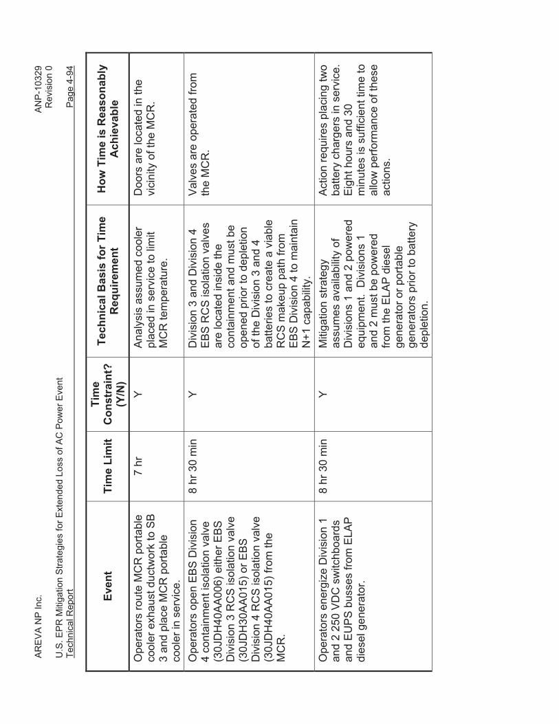
AR
EV
A N
P In
c.
A
NP
-103
29
Rev
isio
n 0
U.S
. EP
R M
itiga
tion
Stra
tegi
es fo
r Ext
ende
d Lo
ss o
f AC
Pow
er E
vent
Te
chni
cal R
epor
t
Pag
e 4-
94
Even
t Ti
me
Lim
it Ti
me
Con
stra
int?
(Y
/N)
Tech
nica
l Bas
is fo
r Tim
e R
equi
rem
ent
How
Tim
e is
Rea
sona
bly
Ach
ieva
ble
Ope
rato
rs ro
ute
MC
R p
orta
ble
cool
er e
xhau
st d
uctw
ork
to S
B
3 an
d pl
ace
MC
R p
orta
ble
cool
er in
ser
vice
.
7 hr
Y
Ana
lysi
s as
sum
ed c
oole
r pl
aced
in s
ervi
ce to
lim
it M
CR
tem
pera
ture
.
Doo
rs a
re lo
cate
d in
the
vici
nity
of t
he M
CR
.
Ope
rato
rs o
pen
EB
S D
ivis
ion
4 co
ntai
nmen
t iso
latio
n va
lve
(30J
DH
40A
A00
6) e
ither
EB
S
Div
isio
n 3
RC
S is
olat
ion
valv
e (3
0JD
H30
AA
015)
or E
BS
D
ivis
ion
4 R
CS
isol
atio
n va
lve
(30J
DH
40A
A01
5) fr
om th
e M
CR
.
8 hr
30
min
Y
Div
isio
n 3
and
Div
isio
n 4
EB
S R
CS
isol
atio
n va
lves
ar
e lo
cate
d in
side
the
cont
ainm
ent a
nd m
ust b
e op
ened
prio
r to
depl
etio
n of
the
Div
isio
n 3
and
4 ba
tterie
s to
cre
ate
a vi
able
R
CS
mak
eup
path
from
E
BS
Div
isio
n 4
to m
aint
ain
N+1
cap
abilit
y.
Val
ves
are
oper
ated
from
th
e M
CR
.
Ope
rato
rs e
nerg
ize
Div
isio
n 1
and
2 25
0 V
DC
sw
itchb
oard
s an
d E
UP
S b
usse
s fro
m E
LAP
di
esel
gen
erat
or.
8 hr
30
min
Y
Miti
gatio
n st
rate
gy
assu
mes
ava
ilabi
lity
of
Div
isio
ns 1
and
2 p
ower
ed
equi
pmen
t. D
ivis
ions
1
and
2 m
ust b
e po
wer
ed
from
the
ELA
P d
iese
l ge
nera
tor o
r por
tabl
e ge
nera
tors
prio
r to
batte
ry
depl
etio
n.
Act
ion
requ
ires
plac
ing
two
batte
ry c
harg
ers
in s
ervi
ce.
Eig
ht h
ours
and
30
min
utes
is s
uffic
ient
tim
e to
al
low
per
form
ance
of t
hese
ac
tions
.

AR
EV
A N
P In
c.
A
NP
-103
29
Rev
isio
n 0
U.S
. EP
R M
itiga
tion
Stra
tegi
es fo
r Ext
ende
d Lo
ss o
f AC
Pow
er E
vent
Te
chni
cal R
epor
t
Pag
e 4-
95
Even
t Ti
me
Lim
it Ti
me
Con
stra
int?
(Y
/N)
Tech
nica
l Bas
is fo
r Tim
e R
equi
rem
ent
How
Tim
e is
Rea
sona
bly
Ach
ieva
ble
Ope
rato
rs d
e-en
ergi
ze
Div
isio
n 3
and
4 25
0 VD
C
switc
hboa
rds
and
EU
PS
bu
sses
.
8 hr
30
min
N
N
/A
Act
ion
is p
erfo
rmed
for
equi
pmen
t pro
tect
ion
and
is n
ot re
quire
d fo
r eve
nt
miti
gatio
n. A
ctio
n ca
n be
de
laye
d if
requ
ired
to a
llow
pe
rform
ance
of a
ctio
ns th
at
are
requ
ired
for e
vent
m
itiga
tion.
R
eple
nish
ELA
P d
iese
l ge
nera
tor f
uel o
il st
orag
e ta
nk.
15 h
r Y
ELA
P d
iese
l gen
erat
or is
re
quire
d to
pow
er e
ssen
tial
miti
gatio
n eq
uipm
ent.
The
E
LAP
die
sel g
ener
ator
is
prov
ided
with
a m
inim
um
eigh
t-hou
r fue
l oil
supp
ly.
The
ELA
P d
iese
l gen
erat
or
is p
lace
d in
ser
vice
by
seve
n ho
urs.
Req
uirin
g re
plen
ishm
ent a
t 15
hour
s is
con
serv
ativ
e si
nce
the
ELA
P d
iese
l gen
erat
or w
ill no
t be
at fu
ll lo
ad u
ntil
Div
isio
ns 1
and
2 2
50 V
DC
sw
itchb
oard
s an
d E
UP
S
buss
es a
re c
onne
cted
.
A m
eans
of t
ank
repl
enis
hmen
t exi
sts
that
is
capa
ble
of fi
lling
the
fuel
oil
stor
age
tank
with
in 1
5 ho
urs.
N
ote:
If t
he E
LAP
die
sel
gene
rato
r is
star
ted
earli
er
than
sev
en h
ours
, the
re
quire
d tim
e of
fuel
re
plen
ishm
ent i
s ea
rlier
by
an e
qual
am
ount
.

AR
EV
A N
P In
c.
A
NP
-103
29
Rev
isio
n 0
U.S
. EP
R M
itiga
tion
Stra
tegi
es fo
r Ext
ende
d Lo
ss o
f AC
Pow
er E
vent
Te
chni
cal R
epor
t
Pag
e 4-
96
Even
t Ti
me
Lim
it Ti
me
Con
stra
int?
(Y
/N)
Tech
nica
l Bas
is fo
r Tim
e R
equi
rem
ent
How
Tim
e is
Rea
sona
bly
Ach
ieva
ble
Fire
wat
er s
tora
ge ta
nk is
re
plen
ishe
d fro
m o
ther
so
urce
s us
ing
the
prov
ided
fill
conn
ectio
ns, o
r a p
orta
ble
pum
p an
d w
ater
sup
ply
is
plac
ed in
ser
vice
.
17 h
r
Ana
lysi
s in
dica
ted
that
fire
w
ater
sto
rage
tank
wou
ld
empt
y in
18
hour
s 20
m
inut
es.
Req
uirin
g re
plen
ishm
ent o
r alte
rnat
e so
urce
of f
eed
at 1
7 ho
urs
prov
ides
mar
gin
to lo
ss o
f su
ctio
n.
A m
eans
of t
ank
repl
enis
hmen
t or a
ltern
ate
feed
sup
ply
exis
ts th
at is
ca
pabl
e of
bei
ng p
lace
d in
se
rvic
e w
ithin
17
hour
s.
Mak
eup
to th
e S
FP is
pro
vide
d to
mai
ntai
n at
leas
t ten
ft o
f w
ater
inve
ntor
y ov
er th
e fu
el
asse
mbl
ies.
22 h
r Y
Mai
ntai
n ad
equa
te
radi
olog
ical
shi
eldi
ng fo
r ac
cess
.
Pre
-inst
alle
d en
gine
ered
fe
atur
es a
re p
rovi
ded
to
faci
litat
e po
ol
repl
enis
hmen
t. A
por
tabl
e se
lf-po
wer
ed R
CS
m
akeu
p pu
mp
is p
lace
d in
se
rvic
e.
24 h
r Y
Ana
lysi
s ve
rifie
d th
at
accu
mul
ator
s w
ill pr
ovid
e re
quire
d R
CS
mak
eup
for
24 h
ours
. A
sou
rce
of
RC
S m
akeu
p is
requ
ired
afte
r 24
hour
s.
A p
orta
ble
pum
p an
d bo
rate
d w
ater
sup
ply
exis
t th
at a
re c
apab
le o
f bei
ng
plac
ed in
ser
vice
with
in 2
4 ho
urs.

AR
EV
A N
P In
c.
A
NP
-103
29
Rev
isio
n 0
U.S
. EP
R M
itiga
tion
Stra
tegi
es fo
r Ext
ende
d Lo
ss o
f AC
Pow
er E
vent
Te
chni
cal R
epor
t
Pag
e 4-
97
Even
t Ti
me
Lim
it Ti
me
Con
stra
int?
(Y
/N)
Tech
nica
l Bas
is fo
r Tim
e R
equi
rem
ent
How
Tim
e is
Rea
sona
bly
Ach
ieva
ble
If di
esel
-driv
en fi
re p
ump
is s
till
bein
g us
ed a
s fe
ed s
ourc
e,
repl
enis
h fu
el o
il st
orag
e ta
nk.
3.5
days
Y
Fuel
oil
stor
age
tank
has
a
min
imum
cap
acity
su
ffici
ent t
o fu
el th
e pu
mp
for 8
4.4
hour
s at
a p
ump
flow
of 6
60 g
pm.
Die
sel-
driv
en fi
re p
ump
is p
lace
d in
ser
vice
by
one
hour
afte
r ev
ent i
nitia
tion.
A m
eans
of t
ank
repl
enis
hmen
t exi
sts
that
is
capa
ble
of fi
lling
the
fuel
oil
stor
age
tank
with
in 3
.5
days
. N
ote:
If th
e di
esel
-driv
en
fire
pum
p is
sta
rted
earli
er
than
1 h
our,
the
requ
ired
time
of fu
el re
plen
ishm
ent
is e
arlie
r by
an e
qual
am
ount
. If
cont
ainm
ent v
entin
g is
the
sele
cted
met
hod
of
cont
ainm
ent p
ress
ure
cont
rol,
the
low
flow
pur
ge fl
ow p
ath
is
open
ed to
con
trol c
onta
inm
ent
pres
sure
.
5.5
days
Y
The
low
flow
pur
ge v
ent
path
mus
t be
plac
ed in
se
rvic
e pr
ior t
o co
ntai
nmen
t pre
ssur
e ex
ceed
ing
30 p
sig
to a
void
ex
ceed
ing
the
desi
gn
pres
sure
of t
he lo
w fl
ow
purg
e du
ctw
ork.
Ana
lysi
s in
dica
tes
that
con
tain
men
t pr
essu
re re
ache
s 30
psi
g at
app
roxi
mat
ely
5.5
days
.
5.5
days
pro
vide
s su
ffici
ent
time
to p
lace
the
low
flow
pu
rge
vent
flow
pat
h in
se
rvic
e.
(Thi
s ac
tion
is o
nly
criti
cal
whe
n th
e lo
w fl
ow p
urge
ve
nt p
ath
is s
elec
ted
for
cont
ainm
ent p
ress
ure
cont
rol.)

AR
EV
A N
P In
c.
A
NP
-103
29
Rev
isio
n 0
U.S
. EP
R M
itiga
tion
Stra
tegi
es fo
r Ext
ende
d Lo
ss o
f AC
Pow
er E
vent
Te
chni
cal R
epor
t
Pag
e 4-
98
Even
t Ti
me
Lim
it Ti
me
Con
stra
int?
(Y
/N)
Tech
nica
l Bas
is fo
r Tim
e R
equi
rem
ent
How
Tim
e is
Rea
sona
bly
Ach
ieva
ble
If co
ntai
nmen
t spr
ay is
the
sele
cted
met
hod
of
cont
ainm
ent p
ress
ure
cont
rol,
a co
ntai
nmen
t spr
ay fl
ow o
f at
leas
t 88.
2 lb
m/s
ec is
initi
ated
to
low
er c
onta
inm
ent p
ress
ure.
14.7
6 da
ys
Y A
naly
sis
indi
cate
d th
at th
e co
ntai
nmen
t ulti
mat
e de
sign
pre
ssur
e sh
all n
ot
be e
xcee
ded
for 1
4.76
da
ys.
Initi
atin
g a
cont
ainm
ent s
pray
flow
of
at le
ast 8
8.2
lbm
/sec
prio
r to
that
tim
e pr
even
ts
exce
edin
g th
e pr
essu
re
limit.
A p
orta
ble
pum
p an
d bo
rate
d w
ater
sup
ply
exis
t th
at a
re c
apab
le o
f bei
ng
plac
ed in
ser
vice
with
in 2
4 ho
urs
to s
uppo
rt M
ode
6 op
erat
ion.
It i
s re
ason
able
to
ass
ume
that
this
pum
p ca
n be
pla
ced
in s
ervi
ce
with
in a
ppro
xim
atel
y tw
o w
eeks
.

AR
EV
A N
P In
c.
A
NP
-103
29
Rev
isio
n 0
U.S
. EP
R M
itiga
tion
Stra
tegi
es fo
r Ext
ende
d Lo
ss o
f AC
Pow
er E
vent
Te
chni
cal R
epor
t
Pag
e 4-
99
Tabl
e 4-
9—Se
quen
ce o
f Eve
nts
– EL
AP
Initi
ated
in M
ode
6
Even
t Ti
me
Lim
it Ti
me
Con
stra
int?
(Y
/N)
Tech
nica
l Bas
is fo
r Tim
e R
equi
rem
ent
Des
crip
tion
of W
hy T
ime
is
Rea
sona
bly
Ach
ieva
ble
(com
men
ts)
LOO
P w
ith lo
ss o
f all
AC
po
wer
exc
ept f
rom
bat
tery
ba
cked
inve
rters
.
0 N
N
/A
N/A
Ope
rato
rs a
ttem
pt to
sta
rt E
DG
s.
2 m
in
N
N/A
N
/A
Cor
e bo
iling
begi
ns.
3 m
in
24 s
ec
N
N/A
N
/A
Four
add
ition
al E
DG
sta
rt at
tem
pts
fail.
9
min
20
sec
N
N
/A
(125
sec
onds
bet
wee
n ea
ch s
tart
atte
mpt
, 15
seco
nds
cran
k tim
e)
SB
O d
iagn
osed
– o
pera
tors
en
ter S
BO
pro
cedu
re.
9 m
in
20 s
ec
N
N/A
N
/A
Ope
rato
rs a
ttem
pt to
sta
rt S
BO
die
sel g
ener
ator
s.
9 m
in
30 s
ec
N
N/A
N
/A
SB
O d
iese
l gen
erat
ors
fail
to
star
t or c
onne
ct to
EP
SS
bu
sses
.
10 m
in
N
N/A
N
/A

AR
EV
A N
P In
c.
A
NP
-103
29
Rev
isio
n 0
U.S
. EP
R M
itiga
tion
Stra
tegi
es fo
r Ext
ende
d Lo
ss o
f AC
Pow
er E
vent
Te
chni
cal R
epor
t
Pag
e 4-
100
Even
t Ti
me
Lim
it Ti
me
Con
stra
int?
(Y
/N)
Tech
nica
l Bas
is fo
r Tim
e R
equi
rem
ent
Des
crip
tion
of W
hy T
ime
is
Rea
sona
bly
Ach
ieva
ble
(com
men
ts)
ELA
P e
vent
is d
iagn
osed
. 10
min
Y
The
SB
O d
iese
l gen
erat
or
is re
quire
d to
be
capa
ble
of
pow
erin
g lo
ads
with
in 1
0 m
inut
es o
f los
s of
all
AC
po
wer
. Th
e E
LAP
eve
nt is
di
agno
sed
upon
failu
re o
f th
e S
BO
die
sel g
ener
ator
to
sta
rt or
load
.
Ope
rato
rs a
re tr
aine
d to
pl
ace
the
SB
O d
iese
l ge
nera
tor i
n se
rvic
e w
ithin
10
min
utes
. P
roce
dura
l gu
idan
ce d
irect
s in
itiat
ion
of E
LAP
miti
gatio
n up
on
failu
re o
f the
SB
O d
iese
l ge
nera
tor t
o st
art o
r loa
d.
Ope
rato
rs th
rottl
e op
en a
ll fo
ur
accu
mul
ator
isol
atio
n va
lves
to
posi
tions
that
hav
e be
en p
re-
dete
rmin
ed to
pro
vide
su
ffici
ent f
low
to m
ake
up fo
r co
re b
oil o
ff.
12 m
in
Y R
eple
nish
men
t of R
CS
in
vent
ory
to m
akeu
p fo
r bo
il of
f is
requ
ired
as s
oon
as p
ract
ical
. S
ince
the
ELA
P e
vent
is d
iagn
osed
at
10
min
utes
, 12
min
utes
is
the
earli
est i
njec
tion
coul
d be
real
istic
ally
ac
hiev
ed.
Acc
umul
ator
isol
atio
n va
lve
brea
kers
are
clo
sed
upon
en
try in
to M
ode
5 fro
m
Mod
e 4.
Val
ves
are
pow
ered
from
the
EU
PS
bu
sses
and
are
ope
rate
d fro
m th
e M
CR
.
Ope
rato
rs o
pen
5 do
ors
in S
B
2 to
lim
it te
mpe
ratu
re ri
se in
sw
itchg
ear r
oom
.
30 m
in
Y A
naly
sis
indi
cate
d th
at S
B
tem
pera
ture
s w
ould
rem
ain
belo
w e
quip
men
t op
erab
ility
lim
its if
spe
cifie
d do
ors
wer
e op
ened
30
min
utes
afte
r eve
nt
initi
atio
n, a
nd fo
rced
ve
ntila
tion
was
initi
ated
by
seve
n ho
urs
afte
r eve
nt
initi
atio
n.
Act
ion
requ
ires
open
ing
five
door
s in
the
sam
e ar
ea
of th
e bu
ildin
g. O
pera
tors
ar
e tra
ined
to o
pen
thes
e do
ors
with
in th
e re
quire
d tim
e.

AR
EV
A N
P In
c.
A
NP
-103
29
Rev
isio
n 0
U.S
. EP
R M
itiga
tion
Stra
tegi
es fo
r Ext
ende
d Lo
ss o
f AC
Pow
er E
vent
Te
chni
cal R
epor
t
Pag
e 4-
101
Even
t Ti
me
Lim
it Ti
me
Con
stra
int?
(Y
/N)
Tech
nica
l Bas
is fo
r Tim
e R
equi
rem
ent
Des
crip
tion
of W
hy T
ime
is
Rea
sona
bly
Ach
ieva
ble
(com
men
ts)
Act
ion
com
plet
ed to
she
d no
n-es
sent
ial l
oads
from
all
250
VD
C s
witc
hboa
rds
and
EU
PS
bu
sses
.
1 hr
10
min
Y
Ana
lysi
s of
bat
tery
cop
ing
time
assu
med
all
non-
esse
ntia
l loa
ds w
ere
disc
onne
cted
by
70
min
utes
afte
r ini
tiatio
n of
th
e ev
ent.
All
non-
esse
ntia
l loa
ds w
ith
the
exce
ptio
n of
the
I&C
ca
bine
ts a
re s
egre
gate
d fro
m e
ssen
tial l
oads
on
a se
para
te lo
ad s
hed
bus.
N
on-e
ssen
tial l
oads
are
sh
ed b
y op
enin
g fo
ur
brea
kers
from
the
MC
R.
It is
reas
onab
le to
ass
ume
that
four
bre
aker
s ca
n be
op
erat
ed fr
om th
e M
CR
w
ithin
60
min
utes
of
reco
gniti
on th
at a
n E
LAP
ev
ent h
as o
ccur
red.
Th
e I&
C c
abin
ets
in e
ach
divi
sion
are
loca
ted
in th
e sa
me
room
. It
is
reas
onab
le to
ass
ume
that
an
ope
rato
r can
reac
h ea
ch ro
om a
nd
de-e
nerg
ize
the
cabi
nets
w
ithin
60
min
utes
of
reco
gniti
on th
at a
n E
LAP
ev
ent h
as o
ccur
red.

AR
EV
A N
P In
c.
A
NP
-103
29
Rev
isio
n 0
U.S
. EP
R M
itiga
tion
Stra
tegi
es fo
r Ext
ende
d Lo
ss o
f AC
Pow
er E
vent
Te
chni
cal R
epor
t
Pag
e 4-
102
Even
t Ti
me
Lim
it Ti
me
Con
stra
int?
(Y
/N)
Tech
nica
l Bas
is fo
r Tim
e R
equi
rem
ent
Des
crip
tion
of W
hy T
ime
is
Rea
sona
bly
Ach
ieva
ble
(com
men
ts)
ELA
P d
iese
l gen
erat
or s
tarte
d,
pow
er is
alig
ned
to th
e pr
imar
y co
olan
t inj
ectio
n pu
mp,
pr
imar
y co
olan
t inj
ectio
n pu
mp
flow
pat
h is
alig
ned,
and
the
prim
ary
cool
ant i
njec
tion
pum
p.
2 hr
Y
Acc
umul
ator
dis
char
ge
valv
e po
sitio
ns a
nd
pres
sure
s ar
e se
t to
prov
ide
at le
ast 2
30 g
pm to
m
ake
up fo
r cor
e bo
il of
f.
Acc
umul
ator
inve
ntor
y is
ap
prox
imat
ely
37,0
00 g
pm,
whi
ch w
ill pr
ovid
e 2
to 2
.5
hour
s of
RC
S in
ject
ion
befo
re th
e ac
cum
ulat
ors
empt
y (n
egle
ctin
g R
CS
in
vent
ory)
. A
sou
rce
of
pum
ped
RC
S in
ject
ion
mus
t be
prov
ided
by
that
tim
e.
The
ELA
P d
iese
l gen
erat
or
and
the
prim
ary
cool
ant
inje
ctio
n pu
mp
are
sta
rted
from
the
MC
R.
All
man
ual
valv
es in
the
prim
ary
cool
ant i
njec
tion
pum
p
flow
pat
h ar
e al
igne
d up
on
entry
into
Mod
e 5.
M
otor
ope
rate
d va
lves
re
quire
d to
alig
n th
e flo
wpa
th a
re o
pera
ted
from
th
e M
CR
. Th
e on
ly lo
cal a
ctio
ns
requ
ired
to p
lace
the
prim
ary
cool
ant i
njec
tion
pum
p a
re to
alig
n tw
o tra
nsfe
r sw
itche
s, s
trip
all
load
s fro
m E
PS
S 4
80V
lo
ad c
ente
r 31B
MB
and
48
0V M
CC
31B
NB
01, a
nd
to c
lose
the
feed
er b
reak
er
to 3
1BN
B01
. Th
ese
actio
ns c
an b
e co
mpl
eted
w
ithin
two
hour
s of
eve
nt
initi
atio
n.

AR
EV
A N
P In
c.
A
NP
-103
29
Rev
isio
n 0
U.S
. EP
R M
itiga
tion
Stra
tegi
es fo
r Ext
ende
d Lo
ss o
f AC
Pow
er E
vent
Te
chni
cal R
epor
t
Pag
e 4-
103
Even
t Ti
me
Lim
it Ti
me
Con
stra
int?
(Y
/N)
Tech
nica
l Bas
is fo
r Tim
e R
equi
rem
ent
Des
crip
tion
of W
hy T
ime
is
Rea
sona
bly
Ach
ieva
ble
(com
men
ts)
Doo
rs a
re o
pene
d to
pro
vide
ve
nt p
ath
from
SFP
are
a to
ex
terio
r.
4 hr
Y
Ven
t pat
h is
requ
ired
to
ensu
re th
at p
ress
uriz
atio
n of
FB
doe
s no
t occ
ur.
Alig
ning
ven
t pat
h re
quire
s pr
oppi
ng fo
ur d
oors
ope
n,
thre
e of
whi
ch a
re o
n th
e sa
me
elev
atio
n. F
our
hour
s is
ade
quat
e tim
e to
ac
com
plis
h th
is ta
sk.
SFP
boi
ling
begi
ns.
4 hr
17
min
N
N
/A
Lim
iting
tim
e fo
r hea
tup
of
SFP.
If
cont
ainm
ent v
entin
g is
the
sele
cted
met
hod
of
cont
ainm
ent p
ress
ure
cont
rol,
the
low
flow
pur
ge fl
ow p
ath
is
open
ed to
con
trol c
onta
inm
ent
pres
sure
.
5 hr
Y
The
low
flow
pur
ge v
ent
path
mus
t be
plac
ed in
se
rvic
e pr
ior t
o co
ntai
nmen
t pre
ssur
e ex
ceed
ing
30 p
sig
to a
void
ex
ceed
ing
the
desi
gn
pres
sure
of t
he lo
w fl
ow
purg
e du
ctw
ork.
Des
ign
pres
sure
of t
he d
uctw
ork
is
35 p
sig;
an
uppe
r lim
it of
30
psi
g fo
r ini
tiatio
n of
pu
rge
prov
ides
mar
gin
to
the
desi
gn p
ress
ure.
A
naly
sis
indi
cate
s th
at
cont
ainm
ent p
ress
ure
reac
hes
30 p
sig
at
appr
oxim
atel
y 5
hour
s.
5 ho
urs
prov
ides
suf
ficie
nt
time
to p
lace
the
low
flow
pu
rge
vent
flow
pat
h in
se
rvic
e.

AR
EV
A N
P In
c.
A
NP
-103
29
Rev
isio
n 0
U.S
. EP
R M
itiga
tion
Stra
tegi
es fo
r Ext
ende
d Lo
ss o
f AC
Pow
er E
vent
Te
chni
cal R
epor
t
Pag
e 4-
104
Even
t Ti
me
Lim
it Ti
me
Con
stra
int?
(Y
/N)
Tech
nica
l Bas
is fo
r Tim
e R
equi
rem
ent
Des
crip
tion
of W
hy T
ime
is
Rea
sona
bly
Ach
ieva
ble
(com
men
ts)
Ele
ctric
al p
ower
is a
ligne
d fro
m th
e E
LAP
die
sel
gene
rato
r to
the
SB
VS
E
Div
isio
ns 1
and
2 s
uppl
y,
exha
ust,
and
batte
ry ro
om
fans
, the
SB
VS
E D
ivis
ion
1 an
d 2
reci
rcul
atio
n da
mpe
r is
man
ually
clo
sed,
exh
aust
da
mpe
r is
man
ually
ope
ned,
an
d th
e su
pply
, exh
aust
, and
ba
ttery
room
fans
are
pla
ced
in s
ervi
ce.
7 hr
Y
Ana
lysi
s in
dica
ted
that
SB
te
mpe
ratu
res
wou
ld re
mai
n be
low
equ
ipm
ent
oper
abili
ty li
mits
if s
peci
fied
door
s w
ere
open
ed 3
0 m
inut
es a
fter e
vent
in
itiat
ion,
and
forc
ed
vent
ilatio
n w
as in
itiat
ed b
y se
ven
hour
s af
ter e
vent
in
itiat
ion.
Act
ion
requ
ires
oper
ator
s to
acc
ess
and
posi
tion
two
dam
pers
in th
e fie
ld.
Sin
ce
the
inst
alle
d fa
ns a
re b
eing
re
pow
ered
, onl
y el
ectri
cal
alig
nmen
t is
requ
ired
to
plac
e th
e fa
ns in
ser
vice
on
ce th
e da
mpe
rs h
ave
been
pos
ition
ed.
Sev
en
hour
s is
ade
quat
e tim
e to
po
sitio
n tw
o da
mpe
rs, a
nd
perfo
rm th
e re
quire
d el
ectri
cal a
lignm
ent.
Ope
rato
rs ro
ute
MC
R p
orta
ble
cool
er e
xhau
st d
uctw
ork
to S
B
3 an
d pl
ace
MC
R p
orta
ble
cool
er in
ser
vice
.
7 hr
Y
Ana
lysi
s as
sum
ed c
oole
r pl
aced
in s
ervi
ce to
lim
it M
CR
tem
pera
ture
.
Doo
rs a
re lo
cate
d in
the
vici
nity
of t
he M
CR
.
Ope
rato
rs e
nerg
ize
Div
isio
n 1
and
2 25
0 V
DC
sw
itchb
oard
s an
d E
UP
S b
usse
s fro
m E
LAP
di
esel
gen
erat
or.
8 hr
30
min
Y
Miti
gatio
n st
rate
gy
assu
mes
ava
ilabi
lity
of
Div
isio
ns 1
and
2 p
ower
ed
equi
pmen
t. D
ivis
ions
1
and
2 m
ust b
e po
wer
ed
from
the
ELA
P d
iese
l ge
nera
tor o
r por
tabl
e ge
nera
tors
prio
r to
batte
ry
depl
etio
n.
Act
ion
requ
ires
plac
ing
two
batte
ry c
harg
ers
in s
ervi
ce.
Eig
ht h
ours
and
30
min
utes
is s
uffic
ient
tim
e to
al
low
per
form
ance
of t
hese
ac
tions
.

AR
EV
A N
P In
c.
A
NP
-103
29
Rev
isio
n 0
U.S
. EP
R M
itiga
tion
Stra
tegi
es fo
r Ext
ende
d Lo
ss o
f AC
Pow
er E
vent
Te
chni
cal R
epor
t
Pag
e 4-
105
Even
t Ti
me
Lim
it Ti
me
Con
stra
int?
(Y
/N)
Tech
nica
l Bas
is fo
r Tim
e R
equi
rem
ent
Des
crip
tion
of W
hy T
ime
is
Rea
sona
bly
Ach
ieva
ble
(com
men
ts)
Ope
rato
rs d
e-en
ergi
ze
Div
isio
n 3
and
4 25
0 VD
C
switc
hboa
rds
and
EU
PS
bu
sses
.
8 hr
30
min
N
N
/A
Act
ion
is p
erfo
rmed
for
equi
pmen
t pro
tect
ion
and
is n
ot re
quire
d fo
r eve
nt
miti
gatio
n. A
ctio
n ca
n be
de
laye
d if
requ
ired
to a
llow
pe
rform
ance
of a
ctio
ns th
at
are
requ
ired
for e
vent
m
itiga
tion.
R
eple
nish
ELA
P d
iese
l ge
nera
tor f
uel o
il st
orag
e ta
nk.
10 h
r Y
ELA
P d
iese
l gen
erat
or is
re
quire
d to
pow
er e
ssen
tial
miti
gatio
n eq
uipm
ent.
The
E
LAP
die
sel g
ener
ator
is
prov
ided
with
a m
inim
um 8
ho
ur fu
el o
il su
pply
. Th
e E
LAP
die
sel g
ener
ator
is
plac
ed in
ser
vice
by
two
hour
s to
pow
er th
e pr
imar
y co
olan
t inj
ectio
n pu
mp.
R
equi
ring
repl
enis
hmen
t at
10 h
ours
is c
onse
rvat
ive
sinc
e th
e E
LAP
die
sel
gene
rato
r will
not b
e at
full
load
unt
il D
ivis
ions
1 a
nd 2
25
0 V
DC
sw
itchb
oard
s an
d E
UP
S b
usse
s ar
e co
nnec
ted.
A m
eans
of t
ank
repl
enis
hmen
t exi
sts
that
is
capa
ble
of fi
lling
the
fuel
oil
stor
age
tank
with
in 1
0 ho
urs.
N
ote:
If th
e E
LAP
die
sel
gene
rato
r is
star
ted
earli
er
than
2 h
ours
, the
requ
ired
time
of fu
el re
plen
ishm
ent
is e
arlie
r by
an e
qual
am
ount
.

AR
EV
A N
P In
c.
A
NP
-103
29
Rev
isio
n 0
U.S
. EP
R M
itiga
tion
Stra
tegi
es fo
r Ext
ende
d Lo
ss o
f AC
Pow
er E
vent
Te
chni
cal R
epor
t
Pag
e 4-
106
Even
t Ti
me
Lim
it Ti
me
Con
stra
int?
(Y
/N)
Tech
nica
l Bas
is fo
r Tim
e R
equi
rem
ent
Des
crip
tion
of W
hy T
ime
is
Rea
sona
bly
Ach
ieva
ble
(com
men
ts)
Mak
eup
to th
e S
FP is
pro
vide
d to
mai
ntai
n at
leas
t ten
ft o
f w
ater
inve
ntor
y ov
er th
e fu
el
asse
mbl
ies.
22 h
r Y
Mai
ntai
n ad
equa
te
radi
olog
ical
shi
eldi
ng fo
r ac
cess
.
Pre
-inst
alle
d en
gine
ered
fe
atur
es a
re p
rovi
ded
to
faci
litat
e po
ol
repl
enis
hmen
t. If
cont
ainm
ent s
pray
is th
e se
lect
ed m
etho
d of
co
ntai
nmen
t pre
ssur
e co
ntro
l, a
cont
ainm
ent s
pray
flow
of a
t le
ast 8
8.2
lbm
/sec
is in
itiat
ed
to lo
wer
con
tain
men
t pre
ssur
e.
24 h
r Y
Ana
lysi
s ve
rifie
d th
at
initi
atin
g 88
.2 lb
m/s
ec
spra
y flo
w a
t 24
hour
s pr
even
ted
exce
edin
g th
e co
ntai
nmen
t ulti
mat
e pr
essu
re li
mit
of 1
33.2
ps
ia.
A p
orta
ble
pum
p an
d bo
rate
d w
ater
sup
ply
exis
t th
at a
re c
apab
le o
f bei
ng
plac
ed in
ser
vice
with
in 2
4 ho
urs.

AREVA NP Inc. ANP-10329 Revision 0 U.S. EPR Mitigation Strategies for Extended Loss of AC Power Event Technical Report Page 4-107
4.1.7 Performance Requirements Equipment
Performance requirements for portable equipment required for long-term event
mitigation (i.e., Phase 2 and 3) are summarized in Table 4-10.
Table 4-10—Performance Requirements for Portable Equipment
Equipment Performance Requirements Interface Requirements Core Cooling
Portable SG Feed Pump
• Pump shall be sized for a flow rate of 660 gpm (330 gpm to each of two SGs).
• Required head increase across the pump shall be 483 ft at 660 gpm.
• Connections are sized for a flow rate of 660 gpm (330 gpm to each of two SGs).
• Connections points are outside the Fire Protection Building (30SGA01AA092), outside SB 1 (30LAR55AA004), inside SB 1 (3030LAR55AA003), or inside SB 4 (30LAR54AA501).
Portable RCS Makeup Pump and Tank (Modes 1 through 5)
• The pump shall be sized for a flow rate of 50 gpm with a head increase across the pump of 1242 ft.
• The pump discharge pressure under these conditions shall be greater than 548.4 psia.
• Connections points are EBS vent line in FB (30JDH10AA506 or 30JDH40AA506).
Containment Integrity Portable Air Compressor or Pressurized Gas Bottle
• The portable air compressor or gas bottle shall be capable of supplying air at a pressure between 58.8 psig and 147 psig with a volume of 1.24 ft3 (35 liters).
• Connections point is CAS vent line in FB (30SCB01AA251).
Portable Spray Pump
• The pump shall be sized for a flow rate of 700 gpm with a head increase across the pump of 447.4 ft.
• The pump discharge pressure under these conditions shall be greater than 209 psia.
• Connections points are inside SB 4 (30JMQ45AA001) or at flanged connections (30JMQ40BR430, 30JMQ40BR420, 30JMQ40BR450).

AREVA NP Inc. ANP-10329 Revision 0 U.S. EPR Mitigation Strategies for Extended Loss of AC Power Event Technical Report Page 4-108
Equipment Performance Requirements Interface Requirements Spent Fuel Pool Cooling
Portable Spent Fuel Pool Makeup Pump and Water Source
• The pump shall be sized for a flow rate of 500 gpm with a discharge head of 130 ft.
• Actual SFP makeup requirement for ELAP event is 140 gpm. This flow rate is enveloped 10 CFR 50.54 (hh)(2) requirement of 500 gpm.
• Connections points are outside FB (30KTC30AA074 or 30KTC30AA084).
Electrical and DC Load Shedding Portable ELAP Diesel Generators
• If one portable ELAP diesel generator is used to repower Divisions 1 and 2, the required output shall be at least 650 kW.
• If Divisions 1 and 2 are powered by separate portable generators, the required output for each shall be at least 350 kW.
• Output voltage shall be 480 VAC.
• Connections points are in SB (31BMB and 32BMB buses).
HVAC Portable Cooler • The cooler (air conditioner)
shall be sized to provide a minimum of 32,000 BTUs/hr of cooling to MCR.
• Hot exhaust from cooler condensing unit is directed to SB 3.
4.2 NTTF 7, Enhancing Spent Fuel Pool Makeup & Instrumentation
4.2.1 NTTF 7.1, Safety-Related Spent Fuel Pool Level Instrumentation
4.2.1.1 Overview
Recommendation 7.1 is a Tier 1 recommendation that resulted in the issuance of NRC
Order EA-12-051 (Reference 2). This order stated that Licensees must provide
sufficiently reliable instrumentation to monitor SFP water level and be capable of
withstanding design basis natural phenomena.
AREVA NP Inc. ANP-10329 Revision 0 U.S. EPR Mitigation Strategies for Extended Loss of AC Power Event Technical Report Page 4-109
4.2.1.2 Conformance
Consistent with the information in Attachment 3 to Order EA-12-051 (Reference 2), the
U.S. EPR addresses the requirements in Attachment 2 to Order EA-12-051 by providing
two physically separate and independent divisions of safety-related SFP level sensing
with two redundant wide range level sensor channels in each division. The instruments
measure the level from the top of the SFP normal operating range to below the top of
the fuel racks. This span provides indication of:
• A level that is adequate to support operation of the normal SFP cooling system.
• A level that is adequate to provide substantial radiation shielding for a person
standing on the SFP operating deck.
• A level where fuel remains covered and actions to implement makeup water
addition should no longer be deferred.
The SFP level instrumentation is safety-related and has the following design features:
• Seismic and environmental qualification of the instruments.
• Independent power supplies.
• Electrical isolation and physical separation between instrument divisions.
• Continuous display in the MCR.
• Routine calibration and testing.
In addition, the following requirements that are specified in Attachment 3 to Order EA-
12-051 are addressed in a manner consistent with JLD-ISG-2012-03 (Reference 12),
Order EA-12-051 (Reference 2), and NEI 12-02, Revision 1 (Reference 16), as
endorsed by JLD-ISG-2012-03.
Arrangement
The SFP includes four SFP wide range level sensors. The safety-related wide range
level sensors are Seismic Category I components. The sensors are located in separate

AREVA NP Inc. ANP-10329 Revision 0 U.S. EPR Mitigation Strategies for Extended Loss of AC Power Event Technical Report Page 4-110
corners, or recesses, of the SFP to provide reasonable protection against missiles and
debris.
Refer to U.S. EPR FSAR Tier 2, Table 3.2.2-1 and Section 9.1.3.6.
Qualification
The wide range level sensors and cabling for the wide range level instrument channels
are qualified to operate for a minimum period of seven days under the following
conditions:
• Radiological conditions for a normal refueling quantity of freshly discharged (100
hours) fuel with the SFP water level where fuel remains covered.
• Temperature of 212 °F and 100% relative humidity.
• Boiling water and/or steam environment.
• Concentrated borated water environment.
Refer to U.S. EPR FSAR Tier 2, Table 3.11-1.
Power Supplies
The primary instrument channels normally receive power from plant vital AC power.
Each of the two divisions of wide range level sensors includes the capability to connect
a sensor directly to a battery-operated portable indication device. The two portable
indication devices provide on demand push-button-activated indication of SFP level with
no dependence on other station power sources. Each portable indication device is
located in the associated division instrumentation and controls (I&C) room, which is
protected and accessible during normal operation, event, and post-event conditions.
The portable indication device batteries are maintained in a charged state during normal
operation with a minimum battery capacity of seven days of on-demand operation.
Refer to U.S. EPR FSAR Tier 2, Sections 9.1.3.1 and 9.1.3.3.2.

AREVA NP Inc. ANP-10329 Revision 0 U.S. EPR Mitigation Strategies for Extended Loss of AC Power Event Technical Report Page 4-111
Accuracy
The accuracy of the wide range level instrument channels is less than ±1 ft over their
total instrument range of 33 ft (from elevation +30’ 0” to +63’ 0”). This configuration
provides reasonable assurance that the instrument channel indication demonstrates
that the stored fuel is covered with water. Accuracy is maintained without recalibration
following a power interruption, change in power source, or connection of a battery-
powered indication device.
Refer to U.S. EPR FSAR Tier 2, Section 9.1.3.6.
Display
Continuous display of the SFP level is available in the MCR.
On-demand indication of the SFP level is available in the I&C rooms in
Divisions 1 and 4. On-demand display is provided by portable battery-powered
indication devices that can be operated independently of normal and emergency station
power sources.
Training
U.S. EPR U.S. EPR FSAR Tier 2, Section 13.2 discusses the U.S. EPR requirements
for development of a training programs for plant personnel. The training program will
demonstrate that the SFP instrumentation is maintained available and reliable in an
ELAP event. Personnel will be trained in the use and the provision of alternate power to
the safety-related level instrument channels.
4.2.2 NTTF 7.3, Plant Technical Specification
4.2.2.1 Overview
Recommendation 7.3 is a Tier 2 recommendation that requests that Plant Technical
Specifications require one train of emergency onsite electrical power to be operable for
SFP makeup/instrumentation when there is irradiated fuel in the SFP, regardless of
plant operating mode.

AREVA NP Inc. ANP-10329 Revision 0 U.S. EPR Mitigation Strategies for Extended Loss of AC Power Event Technical Report Page 4-112
4.2.2.2 Conformance
The EPR Plant Technical Specifications require one train of emergency onsite power to
be available to operate SFP makeup and instrumentation when there is irradiated fuel in
the SFP regardless of the plant operating mode.
Refer to U.S. EPR FSAR Tier 2, Chapter 16, Technical Specification 3.8.11.
4.2.3 NTTF 7.4, Seismically Qualified Spent Fuel Pool Spray System
4.2.3.1 Overview
Recommendation 7.4 is a Tier 2 recommendation that requests that a seismically
qualified means to spray water into SFPs be provided, including an easily accessible
connection to supply water, such as using a portable pump or pumper truck, at grade
level outside of the building.
4.2.3.2 Conformance
Spent Fuel Pool Spray (SFPS) System
The SFPS system is a subsystem of the Nuclear Island Drain and Vent System. The
SFPS system provides a spray cooling function and an alternate fill pipe for makeup to
the SFP. Refer to simplified Figure 4-20.
The SFPS system is a dry system consisting of two separate, redundant trains that are
physically located on opposite sides of the SFP. Piping is routed from ground elevation
to the SFP elevation through stairwells.
Each SFPS train is capable of being supplied water from four sources:
• Fire water distribution system connection within the FB.
• Fire water distribution system connection within either SB 1 (Train 1) or SB 4
(Train 2).
• A separate and independent hose connection, located on the exterior of the FB
at grade elevation, can be used to attach a pumper truck or portable pump.

AREVA NP Inc. ANP-10329 Revision 0 U.S. EPR Mitigation Strategies for Extended Loss of AC Power Event Technical Report Page 4-113
The SFPS system is classified as Supplemented Grade (NS-AQ) and
Seismic Category II. To ensure adequate functionality following a safe shutdown
earthquake (SSE), the following supplemental seismic requirements are imposed:
• For valves and piping - ANSI/ASME B31.1 (Reference 24).
• For other SSC – ASCE 43-05, “Seismic Design Criteria for Structures, Systems,
and Components in Nuclear Facilities” (Reference 23).
This seismic qualification strategy is consistent with the seismic qualification strategy
used for the non-safety-related fire protection system, as described in U.S. EPR FSAR
Tier 2, Section 9.5.1.
Also refer to U.S. EPR FSAR Tier 2, Section 9.3.3.2.1 and Figure 9.3.3-1.
4.3 NTTF 9.3, Enhanced Emergency Preparedness
A portion of Recommendation 9.3 is Tier 1, and requires that enhanced emergency
preparedness staffing and communications be addressed.
4.3.1 Overview
This section describes provisions for enhancing emergency preparedness as it relates
to staffing and communications associated with Recommendation 9.3, outlined in
Enclosure 5 of the March 12, 2012 letter "Request for information pursuant to Title 10 of
the Code of Federal Regulations 50.54(f) regarding Recommendations 2.1, 2.3, and
9.3, of the near-term task force review of insights from the Fukushima Daiichi accident,"
(Reference 9). The letter requested that an assessment of the COMS and equipment
used during an emergency event be provided to identify any enhancements that may be
needed to ensure communications are maintained during a large scale natural event.

AREVA NP Inc. ANP-10329 Revision 0 U.S. EPR Mitigation Strategies for Extended Loss of AC Power Event Technical Report Page 4-114
4.3.2 Conformance
4.3.2.1 Enhanced Emergency Plan Staffing and Communications
4.3.2.1.1 Communications
The U.S. EPR includes onsite COMS that are independent and diverse. The COMS for
the U.S. EPR FSAR is described in U.S. EPR FSAR Tier 2, Section 9.5.2.
As noted in U.S. EPR FSAR Tier 2, Section 9.5.2, the COMS consists of the following
subsystems:
• Portable wireless COMS.
• Digital telephone system.
• PA and alarm system.
• Sound-powered system.
• Emergency offsite communication.
• Security communication.
Each communication subsystem provides an independent mode of communications. A
failure of one subsystem does not affect the capability to communicate using the other
subsystem. These diverse COMS are independent of each other to provide effective
communications, including usage in areas exposed to high ambient noise in the plant.
As noted in U.S. EPR FSAR Tier 2, Section 9.5.2, electrical power from a Class 1E
standby power source is provided for the portable wireless COMS base station,
emergency offsite communication capability, and plant security communications. An
isolation device is placed between non-Class 1E COMS components and the Class 1E
power supply to provide the required independence per IEEE Std 384-1992. The
backup power supplies for other communication subsystems (with the exception of the
sound powered phone system) and components are either from integral DC power units
or other plant backup power supplies based on their operational significance and
AREVA NP Inc. ANP-10329 Revision 0 U.S. EPR Mitigation Strategies for Extended Loss of AC Power Event Technical Report Page 4-115
location. Isolation of the non-safety-related AC sources to the Class 1E uninterruptible
power supply is also provided as described in U.S. EPR FSAR Tier 2, Section 8.3.1.1.9.
U.S. EPR FSAR Tier 2, Section 9.5.2.1.3 discusses the requirements for emergency
response facilities and associated communication capabilities.
U.S. EPR FSAR Tier 2, Section 9.5.2.1.3 describes the offsite COMS that interfaces
with the onsite communication system, including type of connectivity, radio frequency,
normal and backup power supplies, and plant security system interface.
U.S. EPR FSAR Tier 2, Section 9.5.2.1.3 discusses the requirements for emergency
response facilities and associated communication capabilities.
4.3.2.1.2 Staffing
U.S. EPR FSAR Tier 2, Section 13.0 discusses requirements for adequate plant staff
size and technical competence.

AREVA NP Inc. ANP-10329 Revision 0 U.S. EPR Mitigation Strategies for Extended Loss of AC Power Event Technical Report Page 5-1
5.0 REFERENCES
1. NRC Order EA-12-049, “Order Modifying Licenses with Regard to Requirements for Mitigation Strategies for Beyond-Design-Basis External Events,” March 12, 2012.
2. NRC Order EA-12-051, “Order Modifying Licenses with Regard to Reliable Spent Fuel Pool Instrumentation,” March 12, 2012.
3. NEI 12-06, Revision 0, “Diverse and Flexible Coping Strategies (FLEX) Implementation Guide,” Nuclear Energy Institute, August 2012.
4. SECY-11-0093, “Recommendations for Enhancing Reactor Safety in the 21st Century, the Near-Term Task Force Review of Insights from the Fukushima Daiichi Accident,” July 12, 2011.
5. SECY-11-0124, “Recommended Actions to be Taken without Delay from the Near-Term Task Force Report,” September 9, 2011.
6. SECY-11-0137, “Prioritization of Recommended Actions to be Taken in Response to Fukushima Lessons Learned,” October 3, 2011.
7. SECY-12-0025, “Proposed Orders and Requests for Information in Response to Lessons Learned from Japan’s March 11, 2011, Great Tohoku Earthquake and Tsunami,” February 17, 2012.
8. SECY-12-0095, “Tier 3 Program Plans and 6-Month Status Update in Response to Lessons Learned from Japan’s March 11, 2011, Great Tohoku Earthquake and Subsequent Tsunami,” July 13, 2012.
9. NRC Letter, “Request for Information Pursuant to Title 10 of the Code of Federal Regulations 50.54(f) Regarding Recommendations 2.1, 2.3, and 9.3, of the Near-Term Task Force Review of Insights from the Fukushima Dai-Ichi Accident,” March 12 2012.
10. SECY-13-0020, “Third 6-Month Status Update on Response to Lessons Learned from Japan’s March 11, 2011, Great Tohoku Earthquake and Subsequent Tsunami,” February 14, 2013.
11. JLD-ISG-2012-01, “Compliance with Order EA-12-049, Order Modifying Licenses with Regard to Requirements for Mitigation Strategies for Beyond-Design-Basis External Events,” August 29, 2012.
12. JLD-ISG-2012-03, Revision 0, “Compliance with Order EA-12-051, Reliable Spent Fuel Pool Instrumentation,” August 2012.
13. NEI 12-02, Revision 1, “Industry Guidance for Compliance with NRC Order EA-12-051, To Modify Licenses with Regard to Reliable Spent Fuel Pool Instrumentation,” Nuclear Energy Institute, August 2012.

AREVA NP Inc. ANP-10329 Revision 0 U.S. EPR Mitigation Strategies for Extended Loss of AC Power Event Technical Report Page 5-2
14. NRC Letter to AREVA NP Inc., “Implementation of Fukushima Near-Term Task Force Recommendations,” ADAMS Accession Number - ML121040163, April 25, 2012.
15. SRM-12-0025, “Proposed Orders and Requests for Information in Response to Lessons Learned from Japan’s March 11, 2011, Great Tohoku Earthquake and Tsunami,” February 17, 2012.
16. ANP-10263(P)(A), “Codes and Methods Applicability Report for the U.S. EPR,” AREVA NP Inc., November 2007.
17. EMF-2328(P)(A), “PWR Small Break LOCA Evaluation Model, S-RELAP5 Based.”
18. BAW-10240(P) (A), “Incorporation of M5™ Properties in Framatome ANP Approved Methods,” Framatome ANP, Inc., August 2004.
19. BAW-10252PA-00, “Analysis of Containment Response to Pipe Ruptures using GOTHIC,” Framatome ANP, Inc., December 2005.
20. ANP-10299P, Revision 2, “Applicability of AREVA NP Containment Response Evaluation Methodology to the U.S. EPR™ for Large Break LOCA Analysis Technical Report,” AREVA NP Inc., December 2009.
21. Regulatory Guide 1.221, Revision 0, “Design-Basis Hurricane and Hurricane Missiles for Nuclear Power Plants,” October 2011.
22. ASCE 7-10, “Minimum Design Loads for Buildings and Other Structures,” American Society of Civil Engineers, 2010.
23. ASCE 43-05, “Seismic Design Criteria for Structures, Systems and Components in Nuclear Facilities,” American Society of Civil Engineers, 2005.
24. ANSI/ASME B31.1-2004, “Power Piping,” American National Standards Institute/The American Society of Mechanical Engineers, 2004.
25. NUREG-1628, “Staff Responses to Frequently Asked Questions Concerning Decommissioning of Nuclear Power Reactors”, Final Report, June 2000.
26. Regulatory Guide 1.189, Revision 1, “Fire Protection for Nuclear Power Plants,” March 2007.
27. NUMARC 87-00, Revision 1, “Guidelines and Technical Bases for NUMARC Initiatives Addressing Station Blackout at Light Water Reactors”, Nuclear Utility Management and Resources Council (now Nuclear Energy Institute), August 1991.