2013 MY 6.7L OBD Operation · PDF fileFuel Rail Pressure Sensor Circuit Check ... Diesel...
167
Ford Motor Company Revision Date: June 28, 2012 09.01.00.02-Page 1 of 167 2013 MY OBD System Operation Summary for 6.7L Diesel Engines Table of Contents Introduction – OBD-II and HD OBD ........................................................................................................................... 5 OBD-II Systems ......................................................................................................................................... 5 General Description 6.7L Diesel Engine ...................................................................................................................... 6 System Schematic 6.7L Chassis Certified ................................................................................................ 7 NON-METHANE HYDROCARBON (NMHC) CONVERTING CATALYST MONITOR ........................................ 11 Diesel Oxidation Catalyst Efficiency Monitor ..........................................................................................11 Diesel Oxidation Catalyst DPF Regeneration Assistance Monitor .........................................................12 Diesel Oxidation Catalyst SCR Assistance Monitor ...............................................................................12 OXIDES OF NITROGREN (NOx) CONVERTING CATALYST MONITORING..................................................... 12 Selective Catalyst Reduction Catalyst Efficiency Monitor ......................................................................12 Selective Catalyst Reduction Feedback Control Monitors .....................................................................13 Exhaust Temperature Controller Monitor ...............................................................................................14 Selective Catalyst Reduction Tank Level ...............................................................................................15 MISFIRE MONITOR.................................................................................................................................................... 17 Misfire System Overview ........................................................................................................................17 Misfire Algorithm Processing ..................................................................................................................17 FUEL SYSTEM MONITOR ........................................................................................................................................ 19 Fuel System Overview ............................................................................................................................19 Fuel Rail Pressure Sensor Circuit Check ...............................................................................................19 Fuel Rail Pressure Sensor Range Check: ..............................................................................................20 Injector Code Missing/Invalid: .................................................................................................................25 Fuel system pressure control: .................................................................................................................25 Fuel Rail Pressure Monitors: ..................................................................................................................25 Injection Timing / Injection quantity ........................................................................................................26 Zero Fuel Calibration: .............................................................................................................................26 Fuel Mass Observer: (Global Fuel Bias) ................................................................................................28 Global Fuel Timing: .................................................................................................................................29 Feedback control: ...................................................................................................................................30
Transcript of 2013 MY 6.7L OBD Operation · PDF fileFuel Rail Pressure Sensor Circuit Check ... Diesel...
Ford Motor Company Revision Date: June 28, 2012 09.01.00.02-Page 1 of 167
2013 MY OBD System Operation
Summary for 6.7L Diesel Engines
Table of Contents
Introduction – OBD-II and HD OBD ........................................................................................................................... 5
OBD-II Systems ......................................................................................................................................... 5
General Description 6.7L Diesel Engine ...................................................................................................................... 6
System Schematic 6.7L Chassis Certified ................................................................................................ 7
NON-METHANE HYDROCARBON (NMHC) CONVERTING CATALYST MONITOR ........................................ 11
Diesel Oxidation Catalyst Efficiency Monitor .......................................................................................... 11
Diesel Oxidation Catalyst DPF Regeneration Assistance Monitor ......................................................... 12
Diesel Oxidation Catalyst SCR Assistance Monitor ............................................................................... 12
OXIDES OF NITROGREN (NOx) CONVERTING CATALYST MONITORING..................................................... 12
Selective Catalyst Reduction Catalyst Efficiency Monitor ...................................................................... 12
Selective Catalyst Reduction Feedback Control Monitors ..................................................................... 13
Exhaust Temperature Controller Monitor ............................................................................................... 14
Selective Catalyst Reduction Tank Level ............................................................................................... 15
MISFIRE MONITOR .................................................................................................................................................... 17
Misfire System Overview ........................................................................................................................ 17
Misfire Algorithm Processing .................................................................................................................. 17
FUEL SYSTEM MONITOR ........................................................................................................................................ 19
Fuel System Overview ............................................................................................................................ 19
Fuel Rail Pressure Sensor Circuit Check ............................................................................................... 19
Fuel Rail Pressure Sensor Range Check: .............................................................................................. 20
Injector Code Missing/Invalid: ................................................................................................................. 25
Fuel system pressure control: ................................................................................................................. 25
Fuel Rail Pressure Monitors: .................................................................................................................. 25
Injection Timing / Injection quantity ........................................................................................................ 26
Zero Fuel Calibration: ............................................................................................................................. 26
Fuel Mass Observer: (Global Fuel Bias) ................................................................................................ 28
Global Fuel Timing: ................................................................................................................................. 29
Feedback control: ................................................................................................................................... 30
Ford Motor Company Revision Date: June 28, 2012 09.01.00.02-Page 2 of 167
EXHAUST GAS SENSOR MONITOR ...................................................................................................................... 34
Air-Fuel Ratio Sensors: Feedgas NOx Sensor Control Module ............................................................. 34
EXHAUST GAS RECIRCULATION (EGR) SYSTEM MONITOR ........................................................................... 48
EGR Rate System Monitor ..................................................................................................................... 48
EGR Cooler / EGR Cooler Bypass Monitor ............................................................................................ 51
EGR System Slow Response ................................................................................................................. 55
EGR Control Limits Monitor .................................................................................................................... 55
Mass Airflow Closed-loop Control Limits Monitor ................................................................................... 56
BOOST PRESSURE CONTROL SYSTEM MONITORING .................................................................................... 56
Intrusive Turbo Position and Response Monitoring ................................................................................ 56
Intrusive Wastegate Monitoring .............................................................................................................. 59
Functional Overboost Monitoring ............................................................................................................ 60
Functional Underboost Monitoring .......................................................................................................... 60
Threshold Underboost Monitoring .......................................................................................................... 61
Threshold Overboost Monitoring ............................................................................................................ 63
Charge Air Cooler Monitoring ................................................................................................................. 65
PARTICULATE MATTER (PM) FILTER MONITORING ......................................................................................... 66
DPF Filter Efficiency Monitor .................................................................................................................. 66
DPF Filter Missing Substrate Monitor ..................................................................................................... 67
DPF Frequent Regeneration Monitor ..................................................................................................... 68
DPF Incomplete Regeneration Monitor .................................................................................................. 69
DPF Feedback Control Monitors ............................................................................................................ 70
DPF Restriction Monitor .......................................................................................................................... 71
ENGINE COOLING SYSTEM MONITORING .......................................................................................................... 72
Thermostat Monitor ................................................................................................................................. 72
Primary Coolant Temp Dynamic Monitoring ........................................................................................... 75
Secondary Coolant Temp Dynamic Monitoring ...................................................................................... 76
COLD START EMISSION REDUCTION STRATEGY MONITORING................................................................... 77
Cold Start Emission Reduction System Monitor (Only Chassis Cert. Applications) ............................... 77
Cold Start Emission Reduction Component Monitor .............................................................................. 78
Engine Sensors ........................................................................................................................................................... 81
Air Temperature Rationality Test ............................................................................................................ 81
Ambient Air Temperature Physical Range Check .................................................................................. 82
Ambient Air Temperature Plausibility Check .......................................................................................... 84
Barometric Pressure and Manifold Absolute Pressure ........................................................................... 89
Turbine Upstream Pressure Sensor Plausibility Checks ........................................................................ 91
Upstream Turbine Pressure Sensor Signal Range Check ..................................................................... 92
EGR Valve Position Sensor .................................................................................................................... 93
Throttle Position Sensor ......................................................................................................................... 93
Ford Motor Company Revision Date: June 28, 2012 09.01.00.02-Page 3 of 167
EGR Downstream Temperature Sensor Dynamic Plausibility Check .................................................... 93
Engine Coolant & Engine Oil Correlation ............................................................................................... 94
Cam and Crank Sensor: ......................................................................................................................... 98
Mass Air Meter ...................................................................................................................................... 100
MAF Rationality Check ......................................................................................................................... 101
Air Path Leakage Check ....................................................................................................................... 104
Crankcase Ventilation Monitor .............................................................................................................. 106
DEF Pressure Sensor ........................................................................................................................... 107
Reductant Pressure Plausibility Check before Start-up ....................................................................... 108
DEF Pressure Build-up Check at Start-up ............................................................................................ 109
DEF System Pressure Control .............................................................................................................. 110
Reductant Tank Level Sensor .............................................................................................................. 111
Reductant Tank Level Sensor Plausibility Check ................................................................................. 113
Reductant Tank Temperature Sensor .................................................................................................. 113
Exhaust Gas Temperature Sensor Rationality Test ............................................................................. 115
Diesel Particulate Filter Pressure Sensor Rationality Test ................................................................... 118
Diesel Particulate Filter Pressure Offset Test ....................................................................................... 120
Diesel Particulate Filter Pressure Offset Test (DPS) ............................................................................ 122
Engine Outputs .......................................................................................................................................................... 123
EGR Valve Actuator Signal Range Check ............................................................................................ 123
EGR Valve Actuator Jammed Detection .............................................................................................. 123
Throttle Valve Actuator Signal Range Check ....................................................................................... 124
Throttle Valve Actuator Jammed Detection .......................................................................................... 124
ECB Valve Actuator Signal Range Check ............................................................................................ 125
Urea System Pressure Control ............................................................................................................. 126
Reductant Pump Motor ......................................................................................................................... 127
Reductant Dosing Valve (Injector) ........................................................................................................ 129
Reverting Valve..................................................................................................................................... 132
Urea Heaters......................................................................................................................................... 134
Lack of Communication Codes: ............................................................................................................ 140
Glow Plugs ............................................................................................................................................ 142
Turbocharger Actuator Signal Range Check ........................................................................................ 147
Wastegate Vacuum Solenoid Signal Range Check ............................................................................. 147
Miscellaneous ECU Errors: ................................................................................................................... 148
Comprehensive Component Monitor - Transmission ............................................................................................. 149
Transmission Inputs .............................................................................................................................. 149
Transmission Outputs ........................................................................................................................... 152
Transmission Control Module (TCM) .................................................................................................... 156
6R140 (RWD) Transmission with external PCM or TCM ....................................................................................... 158
Ford Motor Company Revision Date: June 28, 2012 09.01.00.02-Page 4 of 167
Transmission Inputs .............................................................................................................................. 158
Transmission Outputs ........................................................................................................................... 159
On Board Diagnostic Executive ................................................................................................................................ 162
Exponentially Weighted Moving Average ................................................................................................................ 163
Serial Data Link MIL Illumination .............................................................................................................................. 164
Calculated Load Value .............................................................................................................................................. 165
I/M Readiness ............................................................................................................................................................ 165
Power Take Off Mode ............................................................................................................................................... 166
In-Use Monitor Performance Ratio ........................................................................................................................... 166
Mode$06 Results ....................................................................................................................................................... 167
Ford Motor Company Revision Date: June 28, 2012 09.01.00.02-Page 5 of 167
Introduction – OBD-II and HD OBD
OBD-II Systems
On Board Diagnostics II - Passenger Cars, Light-Duty Trucks, and Medium-Duty Vehicles and Engines certified under title 13, CCR section 1968.2 California OBD-II applies to all California and "CAA Sec. 177 States" for gasoline engine vehicles up to 14,000 lbs. Gross Vehicle Weight Rating (GVWR) starting in the 1996 MY and all diesel engine vehicles up to 14,000 lbs. GVWR starting in the 1997 MY. "CAA Sec. 177 States" or "California States" are states that have adopted and placed into effect the California Air Resources Board (CARB) regulations for a vehicle class or classes in accordance with Section 177 of the Clean Air Act.. At this time, “CAA Sec. 177 States" are Massachusetts, New York, Vermont and Maine for 2004, Rhode Island, Connecticut, Pennsylvania for 2008, New Jersey, Washington, Oregon for 2009, Maryland for 2011, Delaware for 2014 and New Mexico for 2016. These States receive California-certified vehicles for passenger cars and light trucks, and medium-duty vehicles, up to 14,000 lbs. GVWR." Federal OBD applies to all gasoline engine vehicles up to 8,500 lbs. GVWR starting in the 1996 MY and all diesel engine vehicles up to 8,500 lbs. GVWR starting in the 1997 MY. US Federal only OBD-certified vehicles may use the US Federal allowance to certify to California OBD II but then turn off/disable 0.020" evap leak detection). Starting in the 2004 MY, Federal vehicle over 8,500 lbs. are required to phase in OBD-II. Starting in 2004 MY, gasoline-fueled Medium Duty Passenger Vehicles (MDPVs) are required to have OBD-II. By the 2006 MY, all Federal vehicles from 8,500 to 14,000 lbs. GVWR will have been phased into OBD-II.
Heavy Duty OBD Systems
Heavy Duty On-Board Diagnostics - Heavy-duty engines (>14,000 GVWR) certified to HD OBD under title 13, CCR section 1971.1(d)(7.1.1) or (7.2.2) (i.e., 2010 and beyond model year diesel and gasoline engines that are subject to full HD OBD) Starting in the 2010 MY, California and Federal gasoline-fueled and diesel fueled on-road heavy duty engines used in vehicles over 14,000 lbs. GVWR are required to phase into HD OBD. The phase-in starts with certifying one engine family to HD OBD in the 2010 MY. (2010 MY 6.8L 3V Econoline) By the 2013 MY, all engine families must certify to the HD OBD requirements. Vehicles/engines that do not comply with HD OBD during the phase-in period must comply with EMD+. OBD-II system implementation and operation is described in the remainder of this document.
Ford Motor Company Revision Date: June 28, 2012 09.01.00.02-Page 6 of 167
General Description 6.7L Diesel Engine
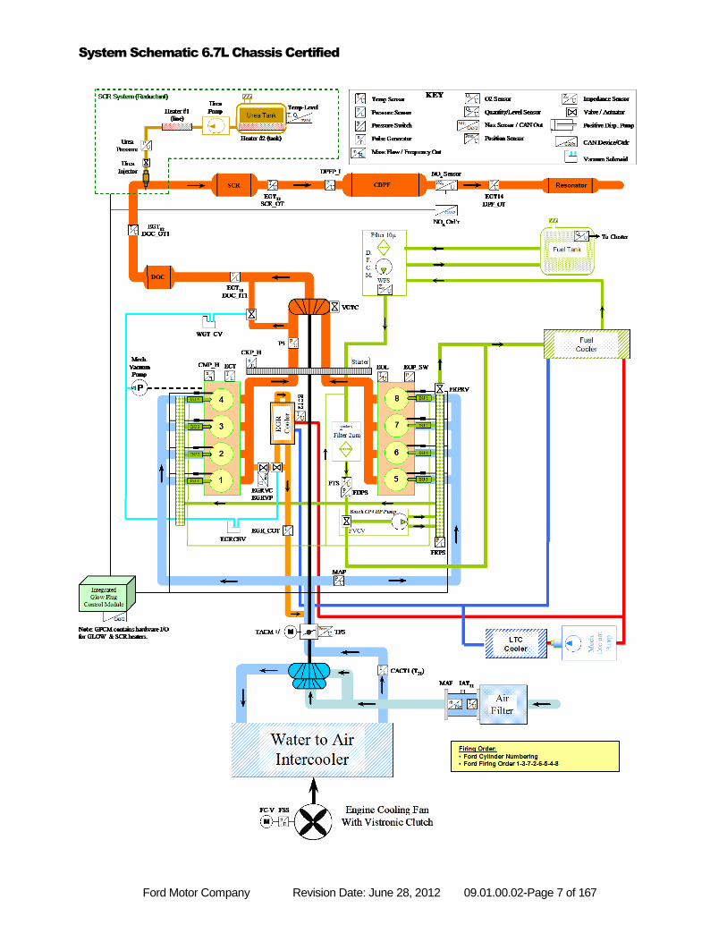
The 6.7L is a V8 engine designed to meet customer expectations of high horsepower and torque with exceptional fuel economy and low NVH. It must do this while meeting the tough emissions standards set by the EPA and CARB. Some of the technologies employed to meet these diverse criteria include a Variable Geometry Turbocharger (VGT), common rail fuel injection system, electronically controlled, cooled EGR, a diesel oxidation catalyst (DOC) , Selective Catalytic Reduction catalyst (SCR), Diesel Exhaust Fluid (DEF) injection system, and a diesel particulate filter (DPF).
The system schematic on the next page shows the path of the air as it is compressed by the turbocharger, cooled
by the air-to-coolant intercooler, and mixed with the cooled EGR gases. The state of this compressed and heated
air is sensed by the manifold absolute pressure (MAP) sensor just before it enters the cylinders and the two
temperature sensors that represent Charge Air Cooler Outlet temperature (CACT1) and EGR Cooler outlet
temperature (EGRCOT). The exhaust gas pressure is measured by the exhaust backpressure (EP) sensor before
it exits through the turbocharger. The exhaust after treatment system consists of a DOC, a SCR, a DPF and a
muffler.
An electronic, proportional valve controls EGR rates with an integral position sensor (EGRP). Flows are determined by valve position and the amount that backpressure exceeds boost pressure. An EGR throttle (EGRTP) is used for regeneration control as well as to optimize the boost pressure vs. backpressure levels. Fuel injection pressure is measured by the high-pressure fuel rail sensor (FRP). Injection pressure is controlled by the high pressure pump and two regulating valves, a Pressure Control Valve (PCV), and a Fuel Metering Unit (MeUn), formerly known as Volume Control Valve (VCV). Engine speed (N) and crankshaft position are determined by the crankshaft position sensor (CKP) which senses a 60 minus 2 tooth target wheel. Camshaft position is determined by the camshaft position sensor (CMP), which senses the profile of a multiple lobed camshaft. Atmospheric pressure is determined by the Barometric Pressure sensor (BARO) mounted internally in the Engine Control Module (ECM). During engine operation, the ECM calculates engine speed from the crankshaft position sensor. The ECM controls engine operation by controlling the piezo injector opening and closing times as well as the pressure at which the fuel is injected, thereby controlling fuel quantity and timing. Simultaneously, airflow is modulated by controlling the turbocharger vane position. Fuel quantity is controlled by injector “on time” (pulse width) and the fuel rail pressure. Desired engine speed is determined from the position of the accelerator pedal.
Ford Motor Company Revision Date: June 28, 2012 09.01.00.02-Page 7 of 167
System Schematic 6.7L Chassis Certified
Ford Motor Company Revision Date: June 28, 2012 09.01.00.02-Page 8 of 167
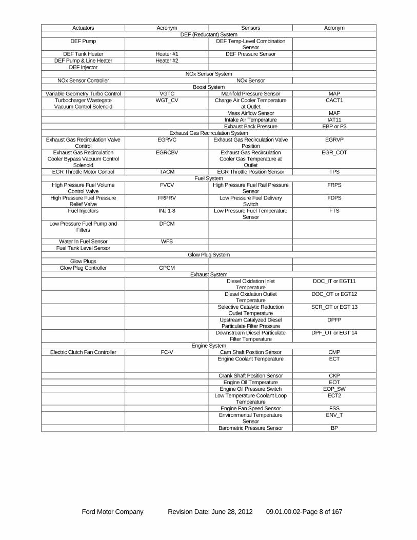
Actuators Acronym Sensors Acronym
DEF (Reductant) System
DEF Pump DEF Temp-Level Combination Sensor
DEF Tank Heater Heater #1 DEF Pressure Sensor
DEF Pump & Line Heater Heater #2
DEF Injector
NOx Sensor System
NOx Sensor Controller NOx Sensor
Boost System
Variable Geometry Turbo Control VGTC Manifold Pressure Sensor MAP
Turbocharger Wastegate Vacuum Control Solenoid
WGT_CV Charge Air Cooler Temperature at Outlet
CACT1
Mass Airflow Sensor MAF
Intake Air Temperature IAT11
Exhaust Back Pressure EBP or P3
Exhaust Gas Recirculation System
Exhaust Gas Recirculation Valve Control
EGRVC Exhaust Gas Recirculation Valve Position
EGRVP
Exhaust Gas Recirculation Cooler Bypass Vacuum Control
Solenoid
EGRCBV Exhaust Gas Recirculation Cooler Gas Temperature at
Outlet
EGR_COT
EGR Throttle Motor Control TACM EGR Throttle Position Sensor TPS
Fuel System
High Pressure Fuel Volume Control Valve
FVCV High Pressure Fuel Rail Pressure Sensor
FRPS
High Pressure Fuel Pressure Relief Valve
FRPRV Low Pressure Fuel Delivery Switch
FDPS
Fuel Injectors INJ 1-8 Low Pressure Fuel Temperature Sensor
FTS
Low Pressure Fuel Pump and Filters
DFCM
Water In Fuel Sensor WFS
Fuel Tank Level Sensor
Glow Plug System
Glow Plugs
Glow Plug Controller GPCM
Exhaust System
Diesel Oxidation Inlet Temperature
DOC_IT or EGT11
Diesel Oxidation Outlet Temperature
DOC_OT or EGT12
Selective Catalytic Reduction Outlet Temperature
SCR_OT or EGT 13
Upstream Catalyzed Diesel Particulate Filter Pressure
DPFP
Downstream Diesel Particulate Filter Temperature
DPF_OT or EGT 14
Engine System
Electric Clutch Fan Controller FC-V Cam Shaft Position Sensor CMP
Engine Coolant Temperature ECT
Crank Shaft Position Sensor CKP
Engine Oil Temperature EOT
Engine Oil Pressure Switch EOP_SW
Low Temperature Coolant Loop Temperature
ECT2
Engine Fan Speed Sensor FSS
Environmental Temperature Sensor
ENV_T
Barometric Pressure Sensor BP
Ford Motor Company Revision Date: June 28, 2012 09.01.00.02-Page 9 of 167
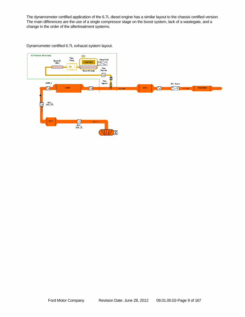
The dynamometer certified application of the 6.7L diesel engine has a similar layout to the chassis certified version.
The main differences are the use of a single compressor stage on the boost system, lack of a wastegate, and a
change in the order of the aftertreatment systems.
Dynamometer certified 6.7L exhaust system layout.
Ford Motor Company Revision Date: June 28, 2012 09.01.00.02-Page 10 of 167
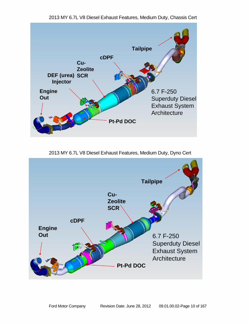
2013 MY 6.7L V8 Diesel Exhaust Features, Medium Duty, Chassis Cert
2013 MY 6.7L V8 Diesel Exhaust Features, Medium Duty, Dyno Cert
6.7 F-250
Superduty Diesel
Exhaust System
Architecture
Pt-Pd DOC
Cu-
Zeolite
SCR
cDPF
Tailpipe
Engine
Out
DEF (urea)
Injector
6.7 F-250
Superduty Diesel
Exhaust System
ArchitecturePt-Pd DOC
Cu-
Zeolite
SCR
cDPF
Engine
Out
Tailpipe
Ford Motor Company Revision Date: June 28, 2012 09.01.00.02-Page 11 of 167
NON-METHANE HYDROCARBON (NMHC) CONVERTING CATALYST MONITOR
Diesel Oxidation Catalyst Efficiency Monitor
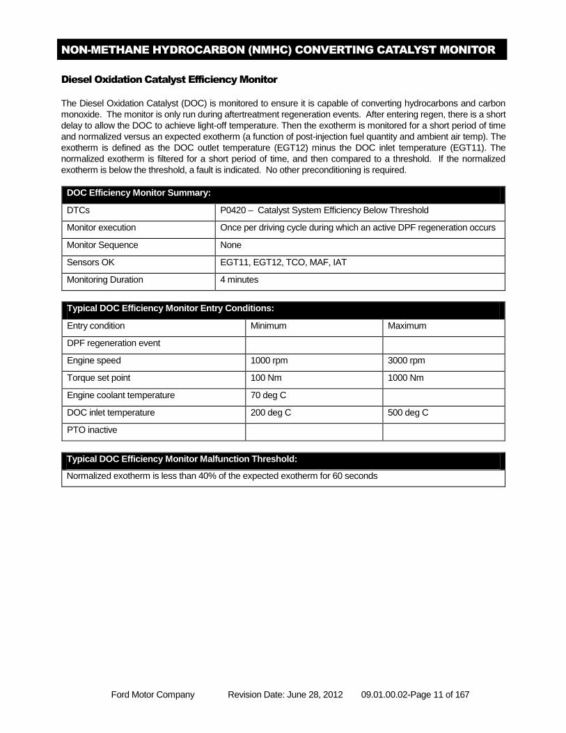
The Diesel Oxidation Catalyst (DOC) is monitored to ensure it is capable of converting hydrocarbons and carbon
monoxide. The monitor is only run during aftertreatment regeneration events. After entering regen, there is a short
delay to allow the DOC to achieve light-off temperature. Then the exotherm is monitored for a short period of time
and normalized versus an expected exotherm (a function of post-injection fuel quantity and ambient air temp). The
exotherm is defined as the DOC outlet temperature (EGT12) minus the DOC inlet temperature (EGT11). The
normalized exotherm is filtered for a short period of time, and then compared to a threshold. If the normalized
exotherm is below the threshold, a fault is indicated. No other preconditioning is required.
DOC Efficiency Monitor Summary:
DTCs P0420 – Catalyst System Efficiency Below Threshold
Monitor execution Once per driving cycle during which an active DPF regeneration occurs
Monitor Sequence None
Sensors OK EGT11, EGT12, TCO, MAF, IAT
Monitoring Duration 4 minutes
Typical DOC Efficiency Monitor Entry Conditions:
Entry condition Minimum Maximum
DPF regeneration event
Engine speed 1000 rpm 3000 rpm
Torque set point 100 Nm 1000 Nm
Engine coolant temperature 70 deg C
DOC inlet temperature 200 deg C 500 deg C
PTO inactive
Typical DOC Efficiency Monitor Malfunction Threshold:
Normalized exotherm is less than 40% of the expected exotherm for 60 seconds
Ford Motor Company Revision Date: June 28, 2012 09.01.00.02-Page 12 of 167
Diesel Oxidation Catalyst DPF Regeneration Assistance Monitor
The DOC is monitored to ensure it is capable of generating a sufficient exotherm to allow DPF regeneration events
by burning the soot which is stored in the Diesel Particulate Filter (DPF). This is accomplished with the same
diagnostic described above for the DOC Catalyst Efficiency Monitor.
Diesel Oxidation Catalyst SCR Assistance Monitor
The DOC in this system is not utilized to provide any changes in the feedgas constituency that would aid in the
proper SCR operation.
OXIDES OF NITROGREN (NOx) CONVERTING CATALYST MONITORING
Selective Catalyst Reduction Catalyst Efficiency Monitor
The SCR catalyst is monitored to ensure it is capable of NOx conversion. The concentration of NOx upstream of
the SCR is calculated based on a model. NOx concentration downstream of the SCR is measured with a NOx
sensor. Using these concentrations, the cumulative efficiency of the SCR catalyst is calculated and compared to a
threshold. If the cumulative efficiency is below this threshold at the end of the sample period (approx 1 minute), a
fault will be indicated.
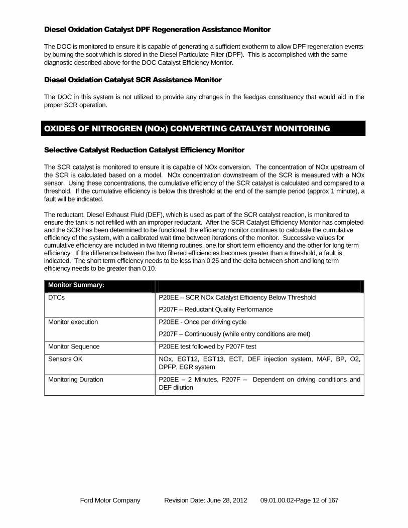
The reductant, Diesel Exhaust Fluid (DEF), which is used as part of the SCR catalyst reaction, is monitored to ensure the tank is not refilled with an improper reductant. After the SCR Catalyst Efficiency Monitor has completed and the SCR has been determined to be functional, the efficiency monitor continues to calculate the cumulative efficiency of the system, with a calibrated wait time between iterations of the monitor. Successive values for cumulative efficiency are included in two filtering routines, one for short term efficiency and the other for long term efficiency. If the difference between the two filtered efficiencies becomes greater than a threshold, a fault is indicated. The short term efficiency needs to be less than 0.25 and the delta between short and long term efficiency needs to be greater than 0.10.
Monitor Summary:
DTCs P20EE – SCR NOx Catalyst Efficiency Below Threshold
P207F – Reductant Quality Performance
Monitor execution P20EE - Once per driving cycle
P207F – Continuously (while entry conditions are met)
Monitor Sequence P20EE test followed by P207F test
Sensors OK NOx, EGT12, EGT13, ECT, DEF injection system, MAF, BP, O2,
DPFP, EGR system
Monitoring Duration P20EE – 2 Minutes, P207F – Dependent on driving conditions and
DEF dilution
Ford Motor Company Revision Date: June 28, 2012 09.01.00.02-Page 13 of 167
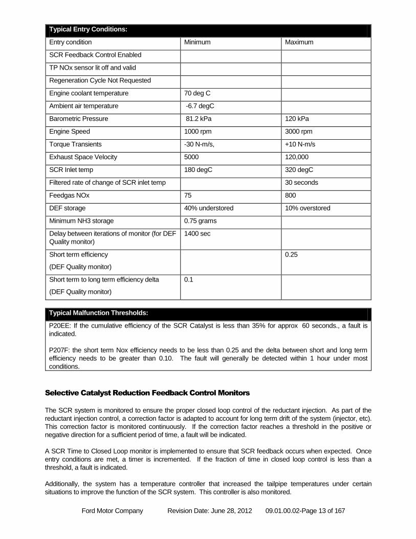
Typical Entry Conditions:
Entry condition Minimum Maximum
SCR Feedback Control Enabled
TP NOx sensor lit off and valid
Regeneration Cycle Not Requested
Engine coolant temperature 70 deg C
Ambient air temperature -6.7 degC
Barometric Pressure 81.2 kPa 120 kPa
Engine Speed 1000 rpm 3000 rpm
Torque Transients -30 N-m/s, +10 N-m/s
Exhaust Space Velocity 5000 120,000
SCR Inlet temp 180 degC 320 degC
Filtered rate of change of SCR inlet temp 30 seconds
Feedgas NOx 75 800
DEF storage 40% understored 10% overstored
Minimum NH3 storage 0.75 grams
Delay between iterations of monitor (for DEF
Quality monitor)
1400 sec
Short term efficiency
(DEF Quality monitor)
0.25
Short term to long term efficiency delta
(DEF Quality monitor)
0.1
Typical Malfunction Thresholds:
P20EE: If the cumulative efficiency of the SCR Catalyst is less than 35% for approx 60 seconds., a fault is
indicated.
P207F: the short term Nox efficiency needs to be less than 0.25 and the delta between short and long term
efficiency needs to be greater than 0.10. The fault will generally be detected within 1 hour under most
conditions.
Selective Catalyst Reduction Feedback Control Monitors
The SCR system is monitored to ensure the proper closed loop control of the reductant injection. As part of the
reductant injection control, a correction factor is adapted to account for long term drift of the system (injector, etc).
This correction factor is monitored continuously. If the correction factor reaches a threshold in the positive or
negative direction for a sufficient period of time, a fault will be indicated.
A SCR Time to Closed Loop monitor is implemented to ensure that SCR feedback occurs when expected. Once
entry conditions are met, a timer is incremented. If the fraction of time in closed loop control is less than a
threshold, a fault is indicated.
Additionally, the system has a temperature controller that increased the tailpipe temperatures under certain
situations to improve the function of the SCR system. This controller is also monitored.
Ford Motor Company Revision Date: June 28, 2012 09.01.00.02-Page 14 of 167
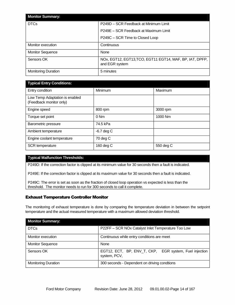
Monitor Summary:
DTCs P249D – SCR Feedback at Minimum Limit
P249E – SCR Feedback at Maximum Limit
P249C – SCR Time to Closed Loop
Monitor execution Continuous
Monitor Sequence None
Sensors OK NOx, EGT12, EGT13,TCO, EGT11 EGT14, MAF, BP, IAT, DPFP,
and EGR system
Monitoring Duration 5 minutes
Typical Entry Conditions:
Entry condition Minimum Maximum
Low Temp Adaptation is enabled
(Feedback monitor only)
Engine speed 800 rpm 3000 rpm
Torque set point 0 Nm 1000 Nm
Barometric pressure 74.5 kPa
Ambient temperature -6.7 deg C
Engine coolant temperature 70 deg C
SCR temperature 160 deg C 550 deg C
Typical Malfunction Thresholds:
P249D: If the correction factor is clipped at its minimum value for 30 seconds then a fault is indicated. P249E: If the correction factor is clipped at its maximum value for 30 seconds then a fault is indicated. P249C: The error is set as soon as the fraction of closed loop operation vs expected is less than the threshold. The monitor needs to run for 300 seconds to call it complete.
Exhaust Temperature Controller Monitor
The monitoring of exhaust temperature is done by comparing the temperature deviation in between the setpoint
temperature and the actual measured temperature with a maximum allowed deviation threshold.
Monitor Summary:
DTCs P22FF – SCR NOx Catalyst Inlet Temperature Too Low
Monitor execution Continuous while entry conditions are meet
Monitor Sequence None
Sensors OK EGT12, ECT, BP, ENV_T, CKP, EGR system, Fuel injection
system, PCV,
Monitoring Duration 300 seconds - Dependent on driving condtions
Ford Motor Company Revision Date: June 28, 2012 09.01.00.02-Page 15 of 167
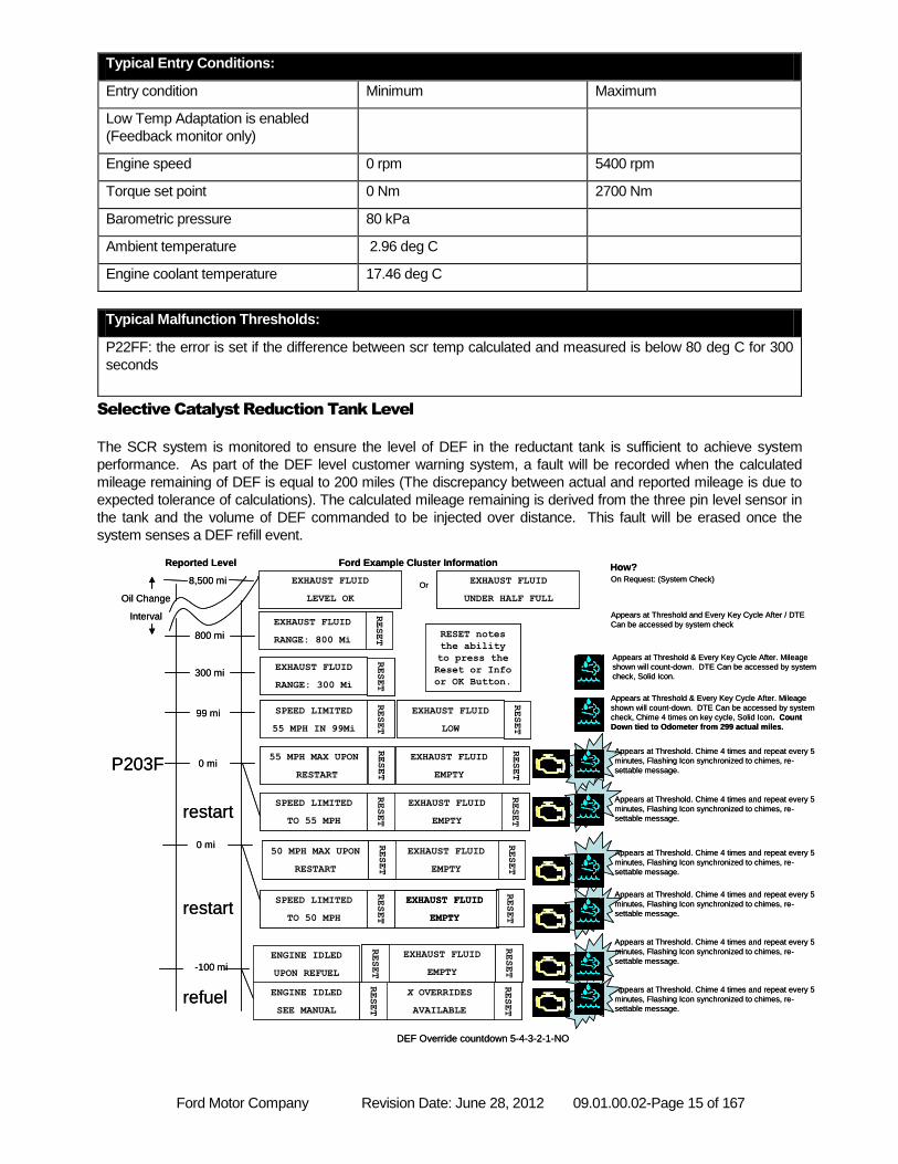
Typical Entry Conditions:
Entry condition Minimum Maximum
Low Temp Adaptation is enabled
(Feedback monitor only)
Engine speed 0 rpm 5400 rpm
Torque set point 0 Nm 2700 Nm
Barometric pressure 80 kPa
Ambient temperature 2.96 deg C
Engine coolant temperature 17.46 deg C
Typical Malfunction Thresholds:
P22FF: the error is set if the difference between scr temp calculated and measured is below 80 deg C for 300
seconds
Selective Catalyst Reduction Tank Level
The SCR system is monitored to ensure the level of DEF in the reductant tank is sufficient to achieve system
performance. As part of the DEF level customer warning system, a fault will be recorded when the calculated
mileage remaining of DEF is equal to 200 miles (The discrepancy between actual and reported mileage is due to
expected tolerance of calculations). The calculated mileage remaining is derived from the three pin level sensor in
the tank and the volume of DEF commanded to be injected over distance. This fault will be erased once the
system senses a DEF refill event.
Appears at Threshold. Chime 4 times and repeat every 5
minutes, Flashing Icon synchronized to chimes, re-
settable message.
Oil Change
Interval
Reported Level
8,500 mi
Ford Example Cluster Information
800 mi
On Request: (System Check)
How?
EXHAUST FLUID
RANGE: 800 Mi
300 miEXHAUST FLUID
RANGE: 300 Mi
Appears at Threshold & Every Key Cycle After. Mileage
shown will count-down. DTE Can be accessed by system
check, Solid Icon.
-100 mi
ENGINE IDLED
UPON REFUEL
X OVERRIDES
AVAILABLE
ENGINE IDLED
SEE MANUAL
RESET
Appears at Threshold and Every Key Cycle After / DTE
Can be accessed by system check
EXHAUST FLUID
EMPTY
RESET
RESET
RESET
RESET
RESET
RESET
EXHAUST FLUID
LEVEL OK
Appears at Threshold & Every Key Cycle After. Mileage
shown will count-down. DTE Can be accessed by system
check, Chime 4 times on key cycle, Solid Icon. Count
Down tied to Odometer from 299 actual miles.
99 mi SPEED LIMITED
55 MPH IN 99Mi
EXHAUST FLUID
LOW
RESET
0 mi55 MPH MAX UPON
RESTART
EXHAUST FLUID
EMPTY
SPEED LIMITED
TO 55 MPH
Appears at Threshold. Chime 4 times and repeat every 5
minutes, Flashing Icon synchronized to chimes, re-
settable message.
RESET
EXHAUST FLUID
EMPTY
RESET
EXHAUST FLUID
EMPTY
50 MPH MAX UPON
RESTART
RESET
EXHAUST FLUID
EMPTY
SPEED LIMITED
TO 50 MPH
RESET
RESET
RESET
RESET
RESET
0 mi
DEF Override countdown 5-4-3-2-1-NO
EXHAUST FLUID
UNDER HALF FULL
Or
RESET notes
the ability
to press the
Reset or Info
or OK Button.
restart
restart
refuel
Appears at Threshold. Chime 4 times and repeat every 5
minutes, Flashing Icon synchronized to chimes, re-
settable message.
Appears at Threshold. Chime 4 times and repeat every 5
minutes, Flashing Icon synchronized to chimes, re-
settable message.
Appears at Threshold. Chime 4 times and repeat every 5
minutes, Flashing Icon synchronized to chimes, re-
settable message.
Appears at Threshold. Chime 4 times and repeat every 5
minutes, Flashing Icon synchronized to chimes, re-
settable message.
P203F
Appears at Threshold. Chime 4 times and repeat every 5
minutes, Flashing Icon synchronized to chimes, re-
settable message.
Oil Change
Interval
Reported Level
8,500 mi
Ford Example Cluster Information
800 mi
On Request: (System Check)
How?
EXHAUST FLUID
RANGE: 800 Mi
300 miEXHAUST FLUID
RANGE: 300 Mi
Appears at Threshold & Every Key Cycle After. Mileage
shown will count-down. DTE Can be accessed by system
check, Solid Icon.
-100 mi
ENGINE IDLED
UPON REFUEL
X OVERRIDES
AVAILABLE
ENGINE IDLED
SEE MANUAL
RESET
Appears at Threshold and Every Key Cycle After / DTE
Can be accessed by system check
EXHAUST FLUID
EMPTY
RESET
RESET
RESET
RESET
RESET
RESET
EXHAUST FLUID
LEVEL OK
Appears at Threshold & Every Key Cycle After. Mileage
shown will count-down. DTE Can be accessed by system
check, Chime 4 times on key cycle, Solid Icon. Count
Down tied to Odometer from 299 actual miles.
99 mi SPEED LIMITED
55 MPH IN 99Mi
EXHAUST FLUID
LOW
RESET
0 mi55 MPH MAX UPON
RESTART
EXHAUST FLUID
EMPTY
SPEED LIMITED
TO 55 MPH
Appears at Threshold. Chime 4 times and repeat every 5
minutes, Flashing Icon synchronized to chimes, re-
settable message.
RESET
EXHAUST FLUID
EMPTY
RESET
EXHAUST FLUID
EMPTY
50 MPH MAX UPON
RESTART
RESET
EXHAUST FLUID
EMPTY
SPEED LIMITED
TO 50 MPH
RESET
RESET
RESET
RESET
RESET
0 mi
DEF Override countdown 5-4-3-2-1-NO
EXHAUST FLUID
UNDER HALF FULL
Or
RESET notes
the ability
to press the
Reset or Info
or OK Button.
restart
restart
refuel
Appears at Threshold. Chime 4 times and repeat every 5
minutes, Flashing Icon synchronized to chimes, re-
settable message.
Appears at Threshold. Chime 4 times and repeat every 5
minutes, Flashing Icon synchronized to chimes, re-
settable message.
Appears at Threshold. Chime 4 times and repeat every 5
minutes, Flashing Icon synchronized to chimes, re-
settable message.
Appears at Threshold. Chime 4 times and repeat every 5
minutes, Flashing Icon synchronized to chimes, re-
settable message.
P203F
Ford Motor Company Revision Date: June 28, 2012 09.01.00.02-Page 16 of 167
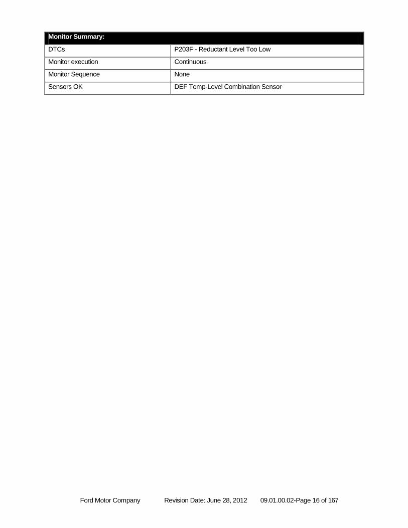
Monitor Summary:
DTCs P203F - Reductant Level Too Low
Monitor execution Continuous
Monitor Sequence None
Sensors OK DEF Temp-Level Combination Sensor
Ford Motor Company Revision Date: June 28, 2012 09.01.00.02-Page 17 of 167
MISFIRE MONITOR
Misfire System Overview
The 6.7L Diesel engine utilizes a Hall Effect sensor (CKP) that processes the edges of a 60-2 tooth stamped target
wheel mounted on the crankshaft. The software gets an edge every 3 degrees and these edges are used for fuel
injection timing, fuel quantity control, and the calculation of engine speed. A software algorithm corrects for
irregularities of the teeth of the target wheel to improve crankshaft signal resolution. A second Hall effect sensor is
used to processes the edges of the three-lobed camshaft (CMP) target. The CMP signal and the window of 2
missing teeth on the crankshaft target wheel indicate proper camshaft to crankshaft position for correct cylinder
timing.
Misfire Algorithm Processing
The Misfire Monitor divides two rotations of the crankshaft into 16 half-segments, each 45 degrees of crankshaft
rotation. The crankshaft speed shows increases due to combustion of fuel in the cylinder followed by decreases
due to friction and other forces between cylinder firing events. The location of the half-segments is chosen such
that for each cylinder one half-segment contains the majority of the higher crankshaft speed values (the "high" half-
segment) and the other half-segment the majority of the lower crankshaft speed values (the "low" half-segment).
The range of crankshaft speed within each half-segment is averaged. The sum of the eight low half-segment
speeds is subtracted from the sum of the eight high half-segment speeds and the result divided by eight to get an
average increase in speed due to combustion. The Misfire Monitor then calculates the difference between the high
and low half-segments for a specific cylinder combustion event and increments a misfire counter for the firing
cylinder if this value is less than 20% of the average increase in speed due to combustion described above.
The Misfire Monitor collects blocks of data consisting of 20 crankshaft rotations. Upon achieving the correct entry
conditions for the Misfire Monitor as described below, the first block of 20 rotations is discarded to ensure stable
idle operation. All subsequent blocks of data are counted unless vehicle conditions change such that the entry
conditions are no longer satisfied. In this case, any data in the current partial block are discarded, along with the
data from the block immediately prior, as stable idle cannot be ensured for these data. The Misfire Monitor
completes once 50 valid blocks (1000 crankshaft revolutions) have been collected, and a fault is reported if a
cylinder shows 350 or more misfire events (out of 500 possible combustion events) in this time.
Certain engine operating parameters are monitored to ensure misfire operates in a region that yields accurate
misfire results. The table below outlines the entry conditions required for executing the misfire monitor algorithm.
Ford Motor Company Revision Date: June 28, 2012 09.01.00.02-Page 18 of 167
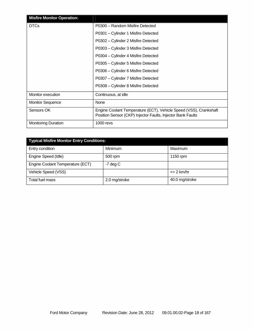
Misfire Monitor Operation:
DTCs P0300 – Random Misfire Detected
P0301 – Cylinder 1 Misfire Detected
P0302 – Cylinder 2 Misfire Detected
P0303 – Cylinder 3 Misfire Detected
P0304 – Cylinder 4 Misfire Detected
P0305 – Cylinder 5 Misfire Detected
P0306 – Cylinder 6 Misfire Detected
P0307 – Cylinder 7 Misfire Detected
P0308 – Cylinder 8 Misfire Detected
Monitor execution Continuous, at idle
Monitor Sequence None
Sensors OK Engine Coolant Temperature (ECT), Vehicle Speed (VSS), Crankshaft
Position Sensor (CKP) Injector Faults, Injector Bank Faults
Monitoring Duration 1000 revs
Typical Misfire Monitor Entry Conditions:
Entry condition Minimum Maximum
Engine Speed (Idle) 500 rpm 1150 rpm
Engine Coolant Temperature (ECT) -7 deg C
Vehicle Speed (VSS) <= 2 km/hr
Total fuel mass 2.0 mg/stroke 40.0 mg/stroke
Ford Motor Company Revision Date: June 28, 2012 09.01.00.02-Page 19 of 167
FUEL SYSTEM MONITOR
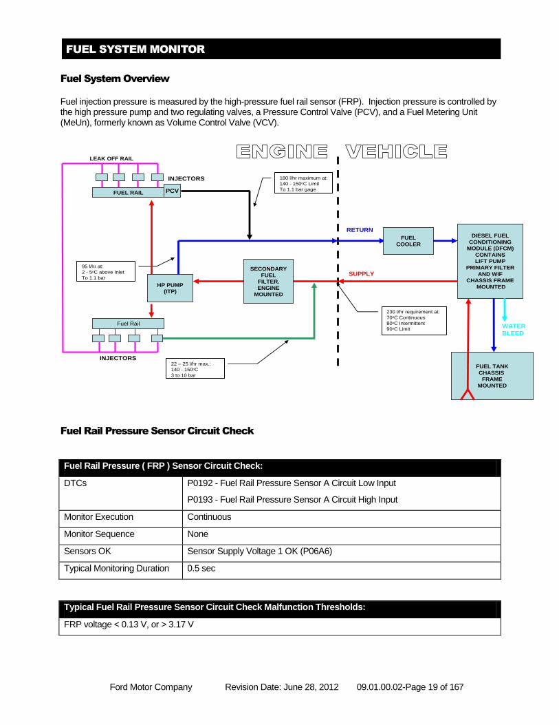
Fuel System Overview
Fuel injection pressure is measured by the high-pressure fuel rail sensor (FRP). Injection pressure is controlled by the high pressure pump and two regulating valves, a Pressure Control Valve (PCV), and a Fuel Metering Unit (MeUn), formerly known as Volume Control Valve (VCV).
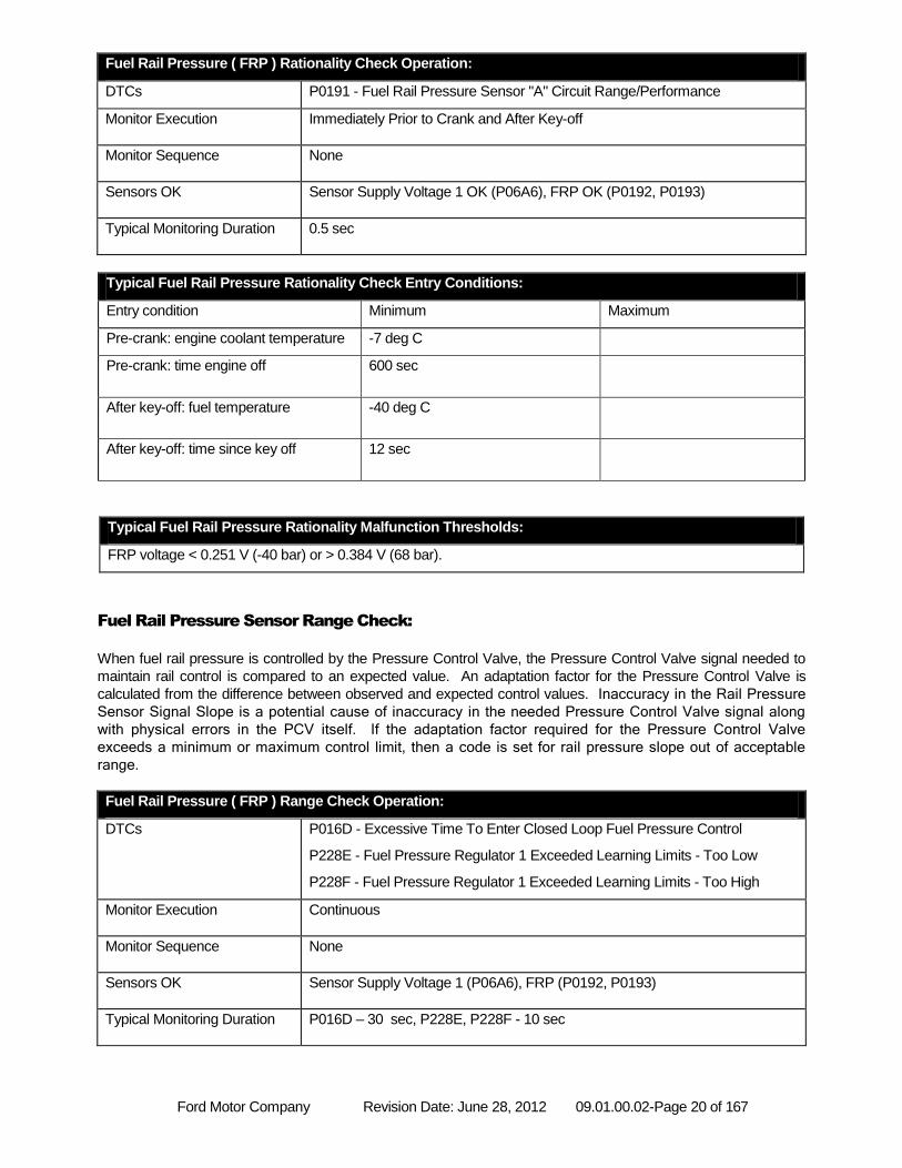
Fuel Rail Pressure Sensor Circuit Check
Fuel Rail Pressure ( FRP ) Sensor Circuit Check:
DTCs P0192 - Fuel Rail Pressure Sensor A Circuit Low Input
P0193 - Fuel Rail Pressure Sensor A Circuit High Input
Monitor Execution Continuous
Monitor Sequence None
Sensors OK Sensor Supply Voltage 1 OK (P06A6)
Typical Monitoring Duration 0.5 sec
Typical Fuel Rail Pressure Sensor Circuit Check Malfunction Thresholds:
FRP voltage < 0.13 V, or > 3.17 V
PCV
HP PUMP
(ITP)
FUEL RAIL
Fuel Rail
DIESEL FUEL
CONDITIONING
MODULE (DFCM)
CONTAINS
LIFT PUMP
PRIMARY FILTER
AND WIF
CHASSIS FRAME
MOUNTED
FUEL TANK
CHASSIS
FRAME
MOUNTED
SUPPLY
RETURN
INJECTORS
LEAK OFF RAIL
WATER
BLEED
FUEL
COOLER
230 l/hr requirement at:
70oC Continuous
80oC Intermittent
90oC Limit
180 l/hr maximum at:
140 - 150oC Limit
To 1.1 bar gage
22 – 25 l/hr max.:
140 - 150oC
3 to 10 bar
95 l/hr at:
2 - 5oC above Inlet
To 1.1 bar
INJECTORS
SECONDARY
FUEL
FILTER.
ENGINE
MOUNTED
Ford Motor Company Revision Date: June 28, 2012 09.01.00.02-Page 20 of 167
Fuel Rail Pressure ( FRP ) Rationality Check Operation:
DTCs P0191 - Fuel Rail Pressure Sensor "A" Circuit Range/Performance
Monitor Execution Immediately Prior to Crank and After Key-off
Monitor Sequence None
Sensors OK Sensor Supply Voltage 1 OK (P06A6), FRP OK (P0192, P0193)
Typical Monitoring Duration 0.5 sec
Typical Fuel Rail Pressure Rationality Check Entry Conditions:
Entry condition Minimum Maximum
Pre-crank: engine coolant temperature -7 deg C
Pre-crank: time engine off 600 sec
After key-off: fuel temperature -40 deg C
After key-off: time since key off 12 sec
Typical Fuel Rail Pressure Rationality Malfunction Thresholds:
FRP voltage < 0.251 V (-40 bar) or > 0.384 V (68 bar).
Fuel Rail Pressure Sensor Range Check:
When fuel rail pressure is controlled by the Pressure Control Valve, the Pressure Control Valve signal needed to
maintain rail control is compared to an expected value. An adaptation factor for the Pressure Control Valve is
calculated from the difference between observed and expected control values. Inaccuracy in the Rail Pressure
Sensor Signal Slope is a potential cause of inaccuracy in the needed Pressure Control Valve signal along
with physical errors in the PCV itself. If the adaptation factor required for the Pressure Control Valve
exceeds a minimum or maximum control limit, then a code is set for rail pressure slope out of acceptable
range.
Fuel Rail Pressure ( FRP ) Range Check Operation:
DTCs P016D - Excessive Time To Enter Closed Loop Fuel Pressure Control
P228E - Fuel Pressure Regulator 1 Exceeded Learning Limits - Too Low
P228F - Fuel Pressure Regulator 1 Exceeded Learning Limits - Too High
Monitor Execution Continuous
Monitor Sequence None
Sensors OK Sensor Supply Voltage 1 (P06A6), FRP (P0192, P0193)
Typical Monitoring Duration P016D – 30 sec, P228E, P228F - 10 sec
Ford Motor Company Revision Date: June 28, 2012 09.01.00.02-Page 21 of 167
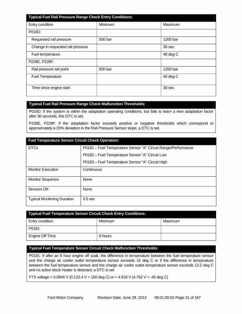
Typical Fuel Rail Pressure Range Check Entry Conditions:
Entry condition Minimum Maximum
P016D:
Requested rail pressure 500 bar 1200 bar
Change in requested rail pressure 30 sec
Fuel temperature 40 deg C
P228E, P228F:
Rail pressure set point 500 bar 1200 bar
Fuel Temperature 40 deg C
Time since engine start 30 sec
Typical Fuel Rail Pressure Range Check Malfunction Thresholds:
P016D: If the system is within the adaptation operating conditions, but fails to learn a new adaptation factor
after 30 seconds, this DTC is set.
P228E, P228F: If the adaptation factor exceeds positive or negative thresholds which correspond to
approximately a 20% deviation in the Rail Pressure Sensor slope, a DTC is set.
Fuel Temperature Sensor Circuit Check Operation:
DTCs P0181 – Fuel Temperature Sensor "A" Circuit Range/Performance
P0182 – Fuel Temperature Sensor "A" Circuit Low
P0183 – Fuel Temperature Sensor "A" Circuit High
Monitor Execution Continuous
Monitor Sequence None
Sensors OK None
Typical Monitoring Duration 0.5 sec
Typical Fuel Temperature Sensor Circuit Check Entry Conditions:
Entry condition Minimum Maximum
P0181:
Engine Off Time 8 hours
Typical Fuel Temperature Sensor Circuit Check Malfunction Thresholds:
P0181: If after an 8 hour engine off soak, the difference in temperature between the fuel temperature sensor
and the charge air cooler outlet temperature sensor exceeds 16 deg C or if the difference in temperature
between the fuel temperature sensor and the charge air cooler outlet temperature sensor exceeds 13.2 deg C
and no active block heater is detected, a DTC is set
FTS voltage < 0.0946 V (0.122.4 V = 150 deg C) or > 4.918 V (4.762 V = -40 deg C)
Ford Motor Company Revision Date: June 28, 2012 09.01.00.02-Page 22 of 167
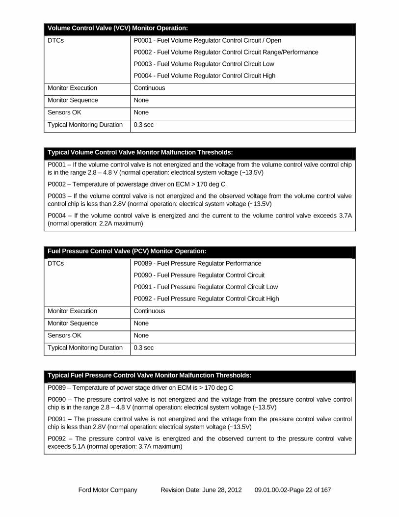
Volume Control Valve (VCV) Monitor Operation:
DTCs P0001 - Fuel Volume Regulator Control Circuit / Open
P0002 - Fuel Volume Regulator Control Circuit Range/Performance
P0003 - Fuel Volume Regulator Control Circuit Low
P0004 - Fuel Volume Regulator Control Circuit High
Monitor Execution Continuous
Monitor Sequence None
Sensors OK None
Typical Monitoring Duration 0.3 sec
Typical Volume Control Valve Monitor Malfunction Thresholds:
P0001 – If the volume control valve is not energized and the voltage from the volume control valve control chip
is in the range 2.8 – 4.8 V (normal operation: electrical system voltage (~13.5V)
P0002 – Temperature of powerstage driver on ECM > 170 deg C
P0003 – If the volume control valve is not energized and the observed voltage from the volume control valve
control chip is less than 2.8V (normal operation: electrical system voltage (~13.5V)
P0004 – If the volume control valve is energized and the current to the volume control valve exceeds 3.7A
(normal operation: 2.2A maximum)
Fuel Pressure Control Valve (PCV) Monitor Operation:
DTCs P0089 - Fuel Pressure Regulator Performance
P0090 - Fuel Pressure Regulator Control Circuit
P0091 - Fuel Pressure Regulator Control Circuit Low
P0092 - Fuel Pressure Regulator Control Circuit High
Monitor Execution Continuous
Monitor Sequence None
Sensors OK None
Typical Monitoring Duration 0.3 sec
Typical Fuel Pressure Control Valve Monitor Malfunction Thresholds:
P0089 – Temperature of power stage driver on ECM is > 170 deg C
P0090 – The pressure control valve is not energized and the voltage from the pressure control valve control
chip is in the range 2.8 – 4.8 V (normal operation: electrical system voltage (~13.5V)
P0091 – The pressure control valve is not energized and the voltage from the pressure control valve control
chip is less than 2.8V (normal operation: electrical system voltage (~13.5V)
P0092 – The pressure control valve is energized and the observed current to the pressure control valve
exceeds 5.1A (normal operation: 3.7A maximum)
Ford Motor Company Revision Date: June 28, 2012 09.01.00.02-Page 23 of 167
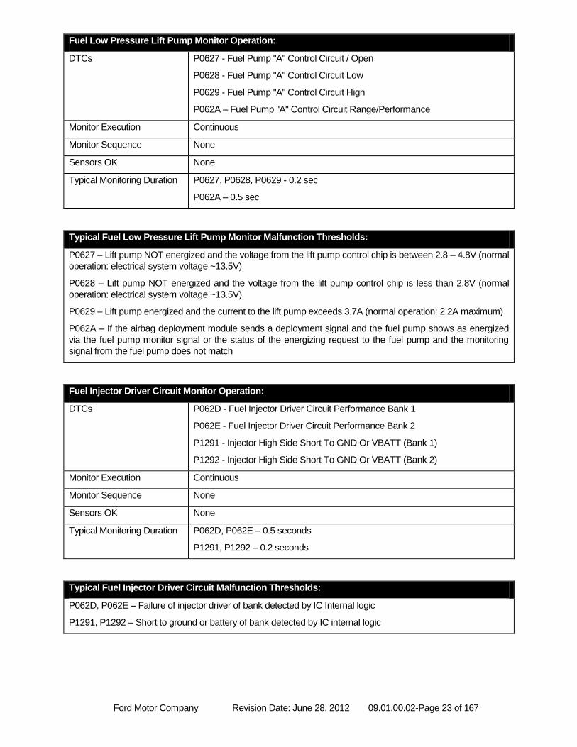
Fuel Low Pressure Lift Pump Monitor Operation:
DTCs P0627 - Fuel Pump "A" Control Circuit / Open
P0628 - Fuel Pump "A" Control Circuit Low
P0629 - Fuel Pump "A" Control Circuit High
P062A – Fuel Pump "A" Control Circuit Range/Performance
Monitor Execution Continuous
Monitor Sequence None
Sensors OK None
Typical Monitoring Duration P0627, P0628, P0629 - 0.2 sec
P062A – 0.5 sec
Typical Fuel Low Pressure Lift Pump Monitor Malfunction Thresholds:
P0627 – Lift pump NOT energized and the voltage from the lift pump control chip is between 2.8 – 4.8V (normal
operation: electrical system voltage ~13.5V)
P0628 – Lift pump NOT energized and the voltage from the lift pump control chip is less than 2.8V (normal
operation: electrical system voltage ~13.5V)
P0629 – Lift pump energized and the current to the lift pump exceeds 3.7A (normal operation: 2.2A maximum)
P062A – If the airbag deployment module sends a deployment signal and the fuel pump shows as energized
via the fuel pump monitor signal or the status of the energizing request to the fuel pump and the monitoring
signal from the fuel pump does not match
Fuel Injector Driver Circuit Monitor Operation:
DTCs P062D - Fuel Injector Driver Circuit Performance Bank 1
P062E - Fuel Injector Driver Circuit Performance Bank 2
P1291 - Injector High Side Short To GND Or VBATT (Bank 1)
P1292 - Injector High Side Short To GND Or VBATT (Bank 2)
Monitor Execution Continuous
Monitor Sequence None
Sensors OK None
Typical Monitoring Duration P062D, P062E – 0.5 seconds
P1291, P1292 – 0.2 seconds
Typical Fuel Injector Driver Circuit Malfunction Thresholds:
P062D, P062E – Failure of injector driver of bank detected by IC Internal logic
P1291, P1292 – Short to ground or battery of bank detected by IC internal logic
Ford Motor Company Revision Date: June 28, 2012 09.01.00.02-Page 24 of 167
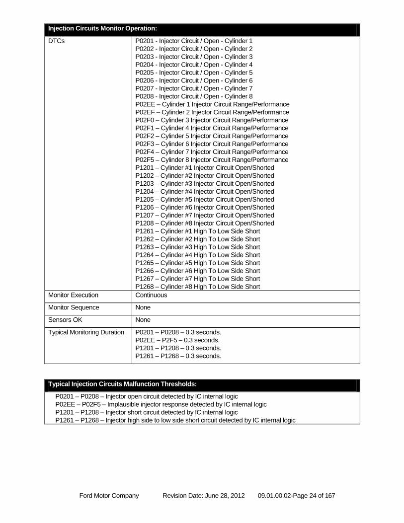
Injection Circuits Monitor Operation:
DTCs P0201 - Injector Circuit / Open - Cylinder 1
P0202 - Injector Circuit / Open - Cylinder 2
P0203 - Injector Circuit / Open - Cylinder 3
P0204 - Injector Circuit / Open - Cylinder 4
P0205 - Injector Circuit / Open - Cylinder 5
P0206 - Injector Circuit / Open - Cylinder 6
P0207 - Injector Circuit / Open - Cylinder 7
P0208 - Injector Circuit / Open - Cylinder 8
P02EE – Cylinder 1 Injector Circuit Range/Performance
P02EF – Cylinder 2 Injector Circuit Range/Performance
P02F0 – Cylinder 3 Injector Circuit Range/Performance
P02F1 – Cylinder 4 Injector Circuit Range/Performance
P02F2 – Cylinder 5 Injector Circuit Range/Performance
P02F3 – Cylinder 6 Injector Circuit Range/Performance
P02F4 – Cylinder 7 Injector Circuit Range/Performance
P02F5 – Cylinder 8 Injector Circuit Range/Performance
P1201 – Cylinder #1 Injector Circuit Open/Shorted
P1202 – Cylinder #2 Injector Circuit Open/Shorted
P1203 – Cylinder #3 Injector Circuit Open/Shorted
P1204 – Cylinder #4 Injector Circuit Open/Shorted
P1205 – Cylinder #5 Injector Circuit Open/Shorted
P1206 – Cylinder #6 Injector Circuit Open/Shorted
P1207 – Cylinder #7 Injector Circuit Open/Shorted
P1208 – Cylinder #8 Injector Circuit Open/Shorted
P1261 – Cylinder #1 High To Low Side Short
P1262 – Cylinder #2 High To Low Side Short
P1263 – Cylinder #3 High To Low Side Short
P1264 – Cylinder #4 High To Low Side Short
P1265 – Cylinder #5 High To Low Side Short
P1266 – Cylinder #6 High To Low Side Short
P1267 – Cylinder #7 High To Low Side Short
P1268 – Cylinder #8 High To Low Side Short
Monitor Execution Continuous
Monitor Sequence None
Sensors OK None
Typical Monitoring Duration P0201 – P0208 – 0.3 seconds.
P02EE – P2F5 – 0.3 seconds.
P1201 – P1208 – 0.3 seconds.
P1261 – P1268 – 0.3 seconds.
Typical Injection Circuits Malfunction Thresholds:
P0201 – P0208 – Injector open circuit detected by IC internal logic
P02EE – P02F5 – Implausible injector response detected by IC internal logic
P1201 – P1208 – Injector short circuit detected by IC internal logic
P1261 – P1268 – Injector high side to low side short circuit detected by IC internal logic
Ford Motor Company Revision Date: June 28, 2012 09.01.00.02-Page 25 of 167
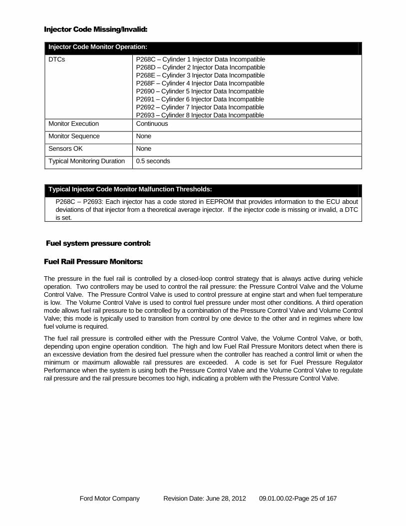
Injector Code Missing/Invalid:
Injector Code Monitor Operation:
DTCs P268C – Cylinder 1 Injector Data Incompatible
P268D – Cylinder 2 Injector Data Incompatible
P268E – Cylinder 3 Injector Data Incompatible
P268F – Cylinder 4 Injector Data Incompatible
P2690 – Cylinder 5 Injector Data Incompatible
P2691 – Cylinder 6 Injector Data Incompatible
P2692 – Cylinder 7 Injector Data Incompatible
P2693 – Cylinder 8 Injector Data Incompatible
Monitor Execution Continuous
Monitor Sequence None
Sensors OK None
Typical Monitoring Duration 0.5 seconds
Typical Injector Code Monitor Malfunction Thresholds:
P268C – P2693: Each injector has a code stored in EEPROM that provides information to the ECU about
deviations of that injector from a theoretical average injector. If the injector code is missing or invalid, a DTC
is set.
Fuel system pressure control:
Fuel Rail Pressure Monitors:
The pressure in the fuel rail is controlled by a closed-loop control strategy that is always active during vehicle
operation. Two controllers may be used to control the rail pressure: the Pressure Control Valve and the Volume
Control Valve. The Pressure Control Valve is used to control pressure at engine start and when fuel temperature
is low. The Volume Control Valve is used to control fuel pressure under most other conditions. A third operation
mode allows fuel rail pressure to be controlled by a combination of the Pressure Control Valve and Volume Control
Valve; this mode is typically used to transition from control by one device to the other and in regimes where low
fuel volume is required.
The fuel rail pressure is controlled either with the Pressure Control Valve, the Volume Control Valve, or both,
depending upon engine operation condition. The high and low Fuel Rail Pressure Monitors detect when there is
an excessive deviation from the desired fuel pressure when the controller has reached a control limit or when the
minimum or maximum allowable rail pressures are exceeded. A code is set for Fuel Pressure Regulator
Performance when the system is using both the Pressure Control Valve and the Volume Control Valve to regulate
rail pressure and the rail pressure becomes too high, indicating a problem with the Pressure Control Valve.
Ford Motor Company Revision Date: June 28, 2012 09.01.00.02-Page 26 of 167
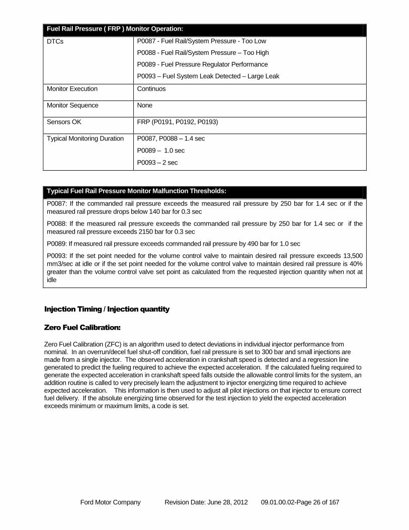
Fuel Rail Pressure ( FRP ) Monitor Operation:
DTCs P0087 - Fuel Rail/System Pressure - Too Low
P0088 - Fuel Rail/System Pressure – Too High
P0089 - Fuel Pressure Regulator Performance
P0093 – Fuel System Leak Detected – Large Leak
Monitor Execution Continuos
Monitor Sequence None
Sensors OK FRP (P0191, P0192, P0193)
Typical Monitoring Duration P0087, P0088 – 1.4 sec
P0089 – 1.0 sec
P0093 – 2 sec
Typical Fuel Rail Pressure Monitor Malfunction Thresholds:
P0087: If the commanded rail pressure exceeds the measured rail pressure by 250 bar for 1.4 sec or if the
measured rail pressure drops below 140 bar for 0.3 sec
P0088: If the measured rail pressure exceeds the commanded rail pressure by 250 bar for 1.4 sec or if the
measured rail pressure exceeds 2150 bar for 0.3 sec
P0089: If measured rail pressure exceeds commanded rail pressure by 490 bar for 1.0 sec
P0093: If the set point needed for the volume control valve to maintain desired rail pressure exceeds 13,500
mm3/sec at idle or if the set point needed for the volume control valve to maintain desired rail pressure is 40%
greater than the volume control valve set point as calculated from the requested injection quantity when not at
idle
Injection Timing / Injection quantity
Zero Fuel Calibration:
Zero Fuel Calibration (ZFC) is an algorithm used to detect deviations in individual injector performance from nominal. In an overrun/decel fuel shut-off condition, fuel rail pressure is set to 300 bar and small injections are made from a single injector. The observed acceleration in crankshaft speed is detected and a regression line generated to predict the fueling required to achieve the expected acceleration. If the calculated fueling required to generate the expected acceleration in crankshaft speed falls outside the allowable control limits for the system, an addition routine is called to very precisely learn the adjustment to injector energizing time required to achieve expected acceleration. This information is then used to adjust all pilot injections on that injector to ensure correct fuel delivery. If the absolute energizing time observed for the test injection to yield the expected acceleration exceeds minimum or maximum limits, a code is set.
Ford Motor Company Revision Date: June 28, 2012 09.01.00.02-Page 27 of 167
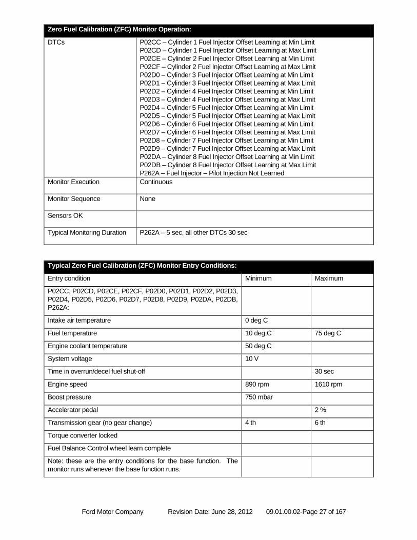
Zero Fuel Calibration (ZFC) Monitor Operation:
DTCs P02CC – Cylinder 1 Fuel Injector Offset Learning at Min Limit
P02CD – Cylinder 1 Fuel Injector Offset Learning at Max Limit
P02CE – Cylinder 2 Fuel Injector Offset Learning at Min Limit
P02CF – Cylinder 2 Fuel Injector Offset Learning at Max Limit
P02D0 – Cylinder 3 Fuel Injector Offset Learning at Min Limit
P02D1 – Cylinder 3 Fuel Injector Offset Learning at Max Limit
P02D2 – Cylinder 4 Fuel Injector Offset Learning at Min Limit
P02D3 – Cylinder 4 Fuel Injector Offset Learning at Max Limit
P02D4 – Cylinder 5 Fuel Injector Offset Learning at Min Limit
P02D5 – Cylinder 5 Fuel Injector Offset Learning at Max Limit
P02D6 – Cylinder 6 Fuel Injector Offset Learning at Min Limit
P02D7 – Cylinder 6 Fuel Injector Offset Learning at Max Limit
P02D8 – Cylinder 7 Fuel Injector Offset Learning at Min Limit
P02D9 – Cylinder 7 Fuel Injector Offset Learning at Max Limit
P02DA – Cylinder 8 Fuel Injector Offset Learning at Min Limit
P02DB – Cylinder 8 Fuel Injector Offset Learning at Max Limit
P262A – Fuel Injector – Pilot Injection Not Learned
Monitor Execution Continuous
Monitor Sequence None
Sensors OK
Typical Monitoring Duration P262A – 5 sec, all other DTCs 30 sec
Typical Zero Fuel Calibration (ZFC) Monitor Entry Conditions:
Entry condition Minimum Maximum
P02CC, P02CD, P02CE, P02CF, P02D0, P02D1, P02D2, P02D3,
P02D4, P02D5, P02D6, P02D7, P02D8, P02D9, P02DA, P02DB,
P262A:
Intake air temperature 0 deg C
Fuel temperature 10 deg C 75 deg C
Engine coolant temperature 50 deg C
System voltage 10 V
Time in overrun/decel fuel shut-off 30 sec
Engine speed 890 rpm 1610 rpm
Boost pressure 750 mbar
Accelerator pedal 2 %
Transmission gear (no gear change) 4 th 6 th
Torque converter locked
Fuel Balance Control wheel learn complete
Note: these are the entry conditions for the base function. The
monitor runs whenever the base function runs.
Ford Motor Company Revision Date: June 28, 2012 09.01.00.02-Page 28 of 167
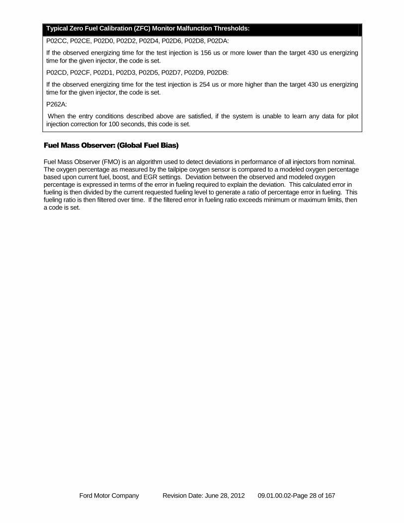
Typical Zero Fuel Calibration (ZFC) Monitor Malfunction Thresholds:
P02CC, P02CE, P02D0, P02D2, P02D4, P02D6, P02D8, P02DA:
If the observed energizing time for the test injection is 156 us or more lower than the target 430 us energizing
time for the given injector, the code is set.
P02CD, P02CF, P02D1, P02D3, P02D5, P02D7, P02D9, P02DB:
If the observed energizing time for the test injection is 254 us or more higher than the target 430 us energizing
time for the given injector, the code is set.
P262A:
When the entry conditions described above are satisfied, if the system is unable to learn any data for pilot
injection correction for 100 seconds, this code is set.
Fuel Mass Observer: (Global Fuel Bias)
Fuel Mass Observer (FMO) is an algorithm used to detect deviations in performance of all injectors from nominal. The oxygen percentage as measured by the tailpipe oxygen sensor is compared to a modeled oxygen percentage based upon current fuel, boost, and EGR settings. Deviation between the observed and modeled oxygen percentage is expressed in terms of the error in fueling required to explain the deviation. This calculated error in fueling is then divided by the current requested fueling level to generate a ratio of percentage error in fueling. This fueling ratio is then filtered over time. If the filtered error in fueling ratio exceeds minimum or maximum limits, then a code is set.
Ford Motor Company Revision Date: June 28, 2012 09.01.00.02-Page 29 of 167
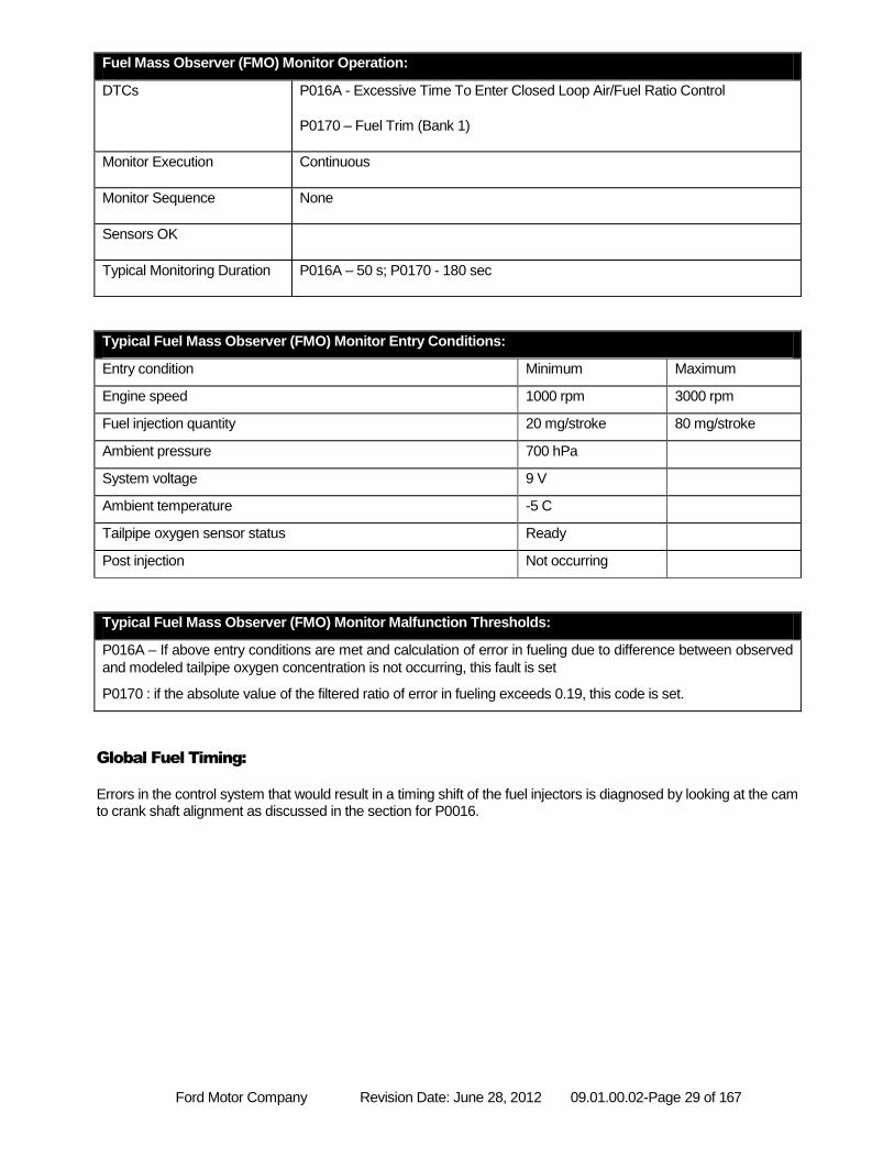
Fuel Mass Observer (FMO) Monitor Operation:
DTCs P016A - Excessive Time To Enter Closed Loop Air/Fuel Ratio Control
P0170 – Fuel Trim (Bank 1)
Monitor Execution Continuous
Monitor Sequence None
Sensors OK
Typical Monitoring Duration P016A – 50 s; P0170 - 180 sec
Typical Fuel Mass Observer (FMO) Monitor Entry Conditions:
Entry condition Minimum Maximum
Engine speed 1000 rpm 3000 rpm
Fuel injection quantity 20 mg/stroke 80 mg/stroke
Ambient pressure 700 hPa
System voltage 9 V
Ambient temperature -5 C
Tailpipe oxygen sensor status Ready
Post injection Not occurring
Typical Fuel Mass Observer (FMO) Monitor Malfunction Thresholds:
P016A – If above entry conditions are met and calculation of error in fueling due to difference between observed
and modeled tailpipe oxygen concentration is not occurring, this fault is set
P0170 : if the absolute value of the filtered ratio of error in fueling exceeds 0.19, this code is set.
Global Fuel Timing:
Errors in the control system that would result in a timing shift of the fuel injectors is diagnosed by looking at the cam to crank shaft alignment as discussed in the section for P0016.
Ford Motor Company Revision Date: June 28, 2012 09.01.00.02-Page 30 of 167
Feedback control:
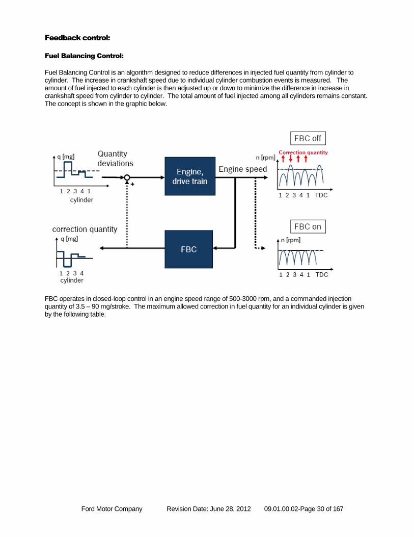
Fuel Balancing Control:
Fuel Balancing Control is an algorithm designed to reduce differences in injected fuel quantity from cylinder to cylinder. The increase in crankshaft speed due to individual cylinder combustion events is measured. The amount of fuel injected to each cylinder is then adjusted up or down to minimize the difference in increase in crankshaft speed from cylinder to cylinder. The total amount of fuel injected among all cylinders remains constant. The concept is shown in the graphic below. FBC operates in closed-loop control in an engine speed range of 500-3000 rpm, and a commanded injection quantity of 3.5 – 90 mg/stroke. The maximum allowed correction in fuel quantity for an individual cylinder is given by the following table.
Ford Motor Company Revision Date: June 28, 2012 09.01.00.02-Page 31 of 167
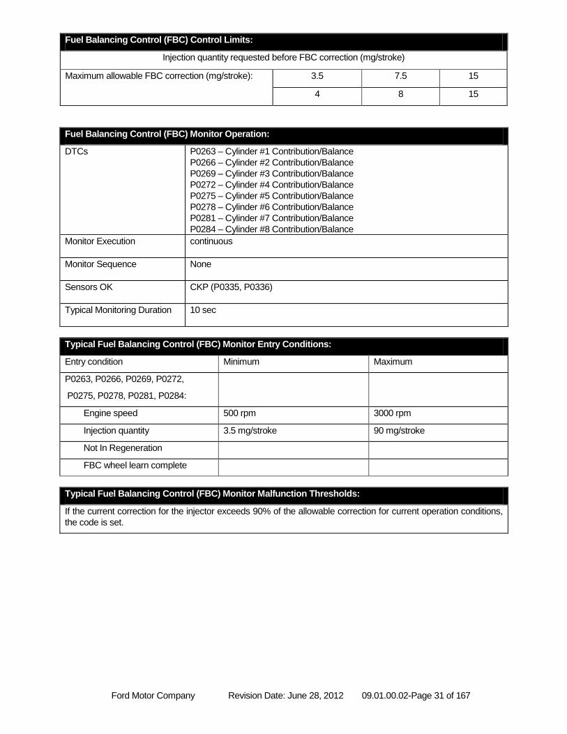
Fuel Balancing Control (FBC) Control Limits:
Injection quantity requested before FBC correction (mg/stroke)
Maximum allowable FBC correction (mg/stroke): 3.5 7.5 15
4 8 15
Fuel Balancing Control (FBC) Monitor Operation:
DTCs P0263 – Cylinder #1 Contribution/Balance
P0266 – Cylinder #2 Contribution/Balance
P0269 – Cylinder #3 Contribution/Balance
P0272 – Cylinder #4 Contribution/Balance
P0275 – Cylinder #5 Contribution/Balance
P0278 – Cylinder #6 Contribution/Balance
P0281 – Cylinder #7 Contribution/Balance
P0284 – Cylinder #8 Contribution/Balance
Monitor Execution continuous
Monitor Sequence None
Sensors OK CKP (P0335, P0336)
Typical Monitoring Duration 10 sec
Typical Fuel Balancing Control (FBC) Monitor Entry Conditions:
Entry condition Minimum Maximum
P0263, P0266, P0269, P0272,
P0275, P0278, P0281, P0284:
Engine speed 500 rpm 3000 rpm
Injection quantity 3.5 mg/stroke 90 mg/stroke
Not In Regeneration
FBC wheel learn complete
Typical Fuel Balancing Control (FBC) Monitor Malfunction Thresholds:
If the current correction for the injector exceeds 90% of the allowable correction for current operation conditions,
the code is set.
Ford Motor Company Revision Date: June 28, 2012 09.01.00.02-Page 32 of 167
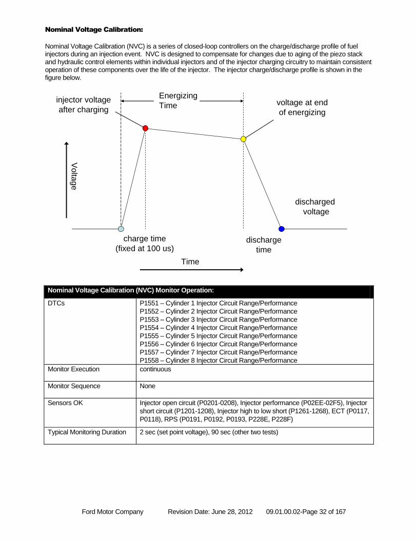
Nominal Voltage Calibration:
Nominal Voltage Calibration (NVC) is a series of closed-loop controllers on the charge/discharge profile of fuel injectors during an injection event. NVC is designed to compensate for changes due to aging of the piezo stack and hydraulic control elements within individual injectors and of the injector charging circuitry to maintain consistent operation of these components over the life of the injector. The injector charge/discharge profile is shown in the figure below.
Nominal Voltage Calibration (NVC) Monitor Operation:
DTCs P1551 – Cylinder 1 Injector Circuit Range/Performance
P1552 – Cylinder 2 Injector Circuit Range/Performance
P1553 – Cylinder 3 Injector Circuit Range/Performance
P1554 – Cylinder 4 Injector Circuit Range/Performance
P1555 – Cylinder 5 Injector Circuit Range/Performance
P1556 – Cylinder 6 Injector Circuit Range/Performance
P1557 – Cylinder 7 Injector Circuit Range/Performance
P1558 – Cylinder 8 Injector Circuit Range/Performance
Monitor Execution continuous
Monitor Sequence None
Sensors OK Injector open circuit (P0201-0208), Injector performance (P02EE-02F5), Injector
short circuit (P1201-1208), Injector high to low short (P1261-1268), ECT (P0117,
P0118), RPS (P0191, P0192, P0193, P228E, P228F)
Typical Monitoring Duration 2 sec (set point voltage), 90 sec (other two tests)
injector voltage
after chargingvoltage at end
of energizing
Energizing
Time
charge time
(fixed at 100 us)discharge
time
discharged
voltage
Volta
ge
Time
Ford Motor Company Revision Date: June 28, 2012 09.01.00.02-Page 33 of 167
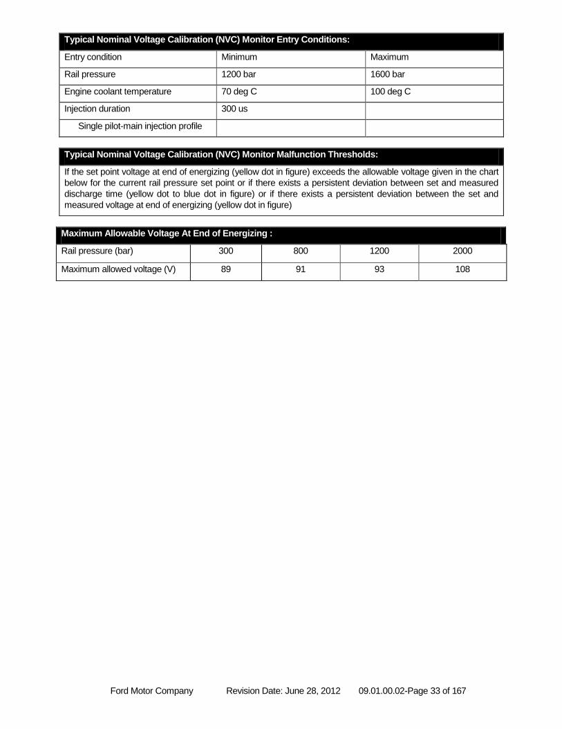
Typical Nominal Voltage Calibration (NVC) Monitor Entry Conditions:
Entry condition Minimum Maximum
Rail pressure 1200 bar 1600 bar
Engine coolant temperature 70 deg C 100 deg C
Injection duration 300 us
Single pilot-main injection profile
Typical Nominal Voltage Calibration (NVC) Monitor Malfunction Thresholds:
If the set point voltage at end of energizing (yellow dot in figure) exceeds the allowable voltage given in the chart
below for the current rail pressure set point or if there exists a persistent deviation between set and measured
discharge time (yellow dot to blue dot in figure) or if there exists a persistent deviation between the set and
measured voltage at end of energizing (yellow dot in figure)
Maximum Allowable Voltage At End of Energizing :
Rail pressure (bar) 300 800 1200 2000
Maximum allowed voltage (V) 89 91 93 108
Ford Motor Company Revision Date: June 28, 2012 09.01.00.02-Page 34 of 167
EXHAUST GAS SENSOR MONITOR
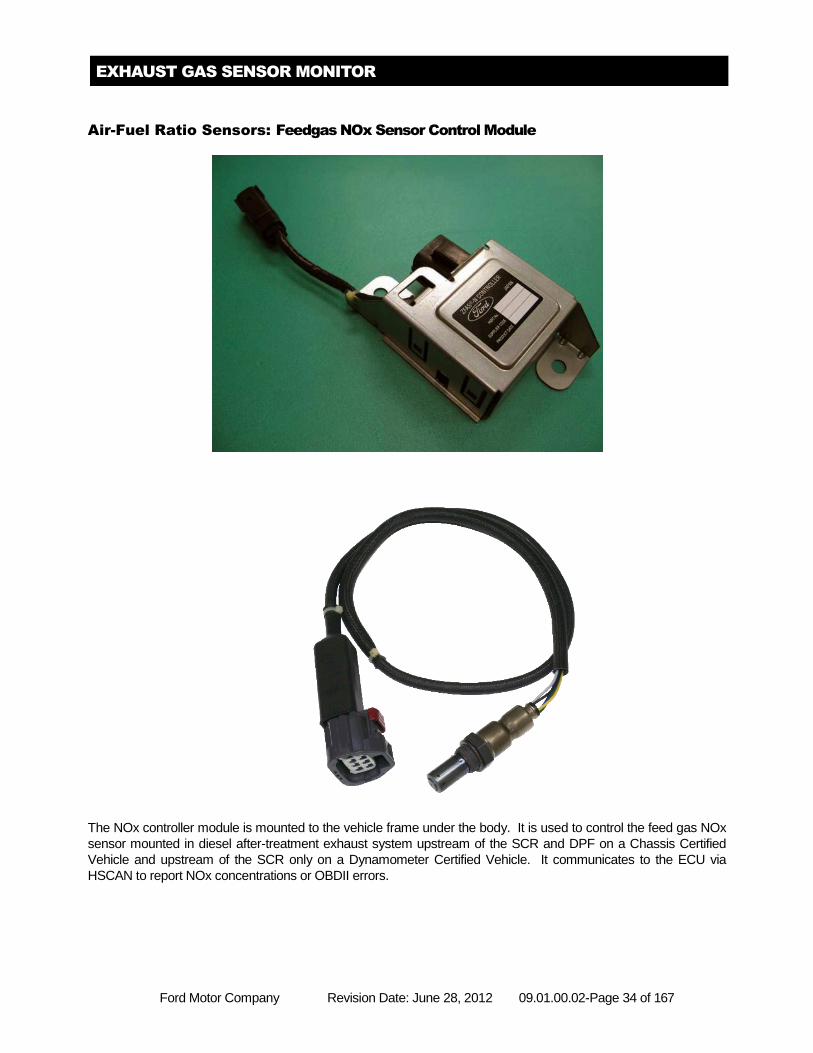
Air-Fuel Ratio Sensors: Feedgas NOx Sensor Control Module
The NOx controller module is mounted to the vehicle frame under the body. It is used to control the feed gas NOx
sensor mounted in diesel after-treatment exhaust system upstream of the SCR and DPF on a Chassis Certified
Vehicle and upstream of the SCR only on a Dynamometer Certified Vehicle. It communicates to the ECU via
HSCAN to report NOx concentrations or OBDII errors.
Ford Motor Company Revision Date: June 28, 2012 09.01.00.02-Page 35 of 167
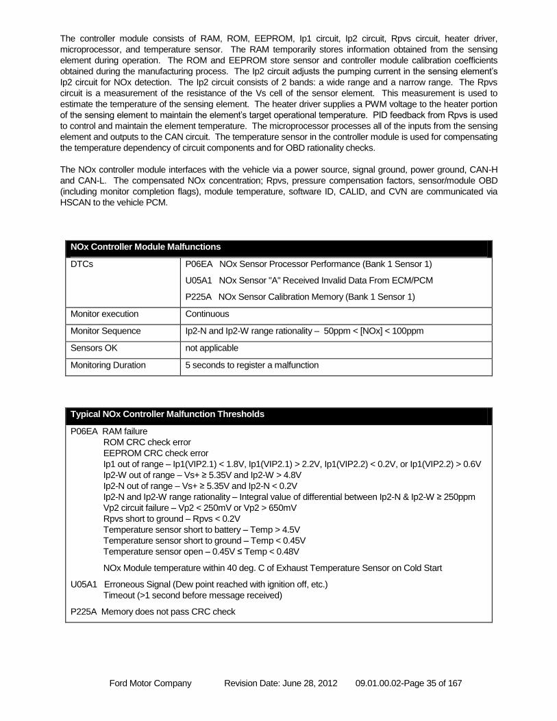
The controller module consists of RAM, ROM, EEPROM, Ip1 circuit, Ip2 circuit, Rpvs circuit, heater driver,
microprocessor, and temperature sensor. The RAM temporarily stores information obtained from the sensing
element during operation. The ROM and EEPROM store sensor and controller module calibration coefficients
obtained during the manufacturing process. The Ip2 circuit adjusts the pumping current in the sensing element’s
Ip2 circuit for NOx detection. The Ip2 circuit consists of 2 bands: a wide range and a narrow range. The Rpvs
circuit is a measurement of the resistance of the Vs cell of the sensor element. This measurement is used to
estimate the temperature of the sensing element. The heater driver supplies a PWM voltage to the heater portion
of the sensing element to maintain the element’s target operational temperature. PID feedback from Rpvs is used
to control and maintain the element temperature. The microprocessor processes all of the inputs from the sensing
element and outputs to the CAN circuit. The temperature sensor in the controller module is used for compensating
the temperature dependency of circuit components and for OBD rationality checks.
The NOx controller module interfaces with the vehicle via a power source, signal ground, power ground, CAN-H
and CAN-L. The compensated NOx concentration; Rpvs, pressure compensation factors, sensor/module OBD
(including monitor completion flags), module temperature, software ID, CALID, and CVN are communicated via
HSCAN to the vehicle PCM.
NOx Controller Module Malfunctions
DTCs P06EA NOx Sensor Processor Performance (Bank 1 Sensor 1)
U05A1 NOx Sensor "A" Received Invalid Data From ECM/PCM
P225A NOx Sensor Calibration Memory (Bank 1 Sensor 1)
Monitor execution Continuous
Monitor Sequence Ip2-N and Ip2-W range rationality – 50ppm < [NOx] < 100ppm
Sensors OK not applicable
Monitoring Duration 5 seconds to register a malfunction
Typical NOx Controller Malfunction Thresholds
P06EA RAM failure
ROM CRC check error
EEPROM CRC check error
Ip1 out of range – Ip1(VIP2.1) < 1.8V, Ip1(VIP2.1) > 2.2V, Ip1(VIP2.2) < 0.2V, or Ip1(VIP2.2) > 0.6V
Ip2-W out of range – Vs+ ≥ 5.35V and Ip2-W > 4.8V
Ip2-N out of range – Vs+ ≥ 5.35V and Ip2-N < 0.2V
Ip2-N and Ip2-W range rationality – Integral value of differential between Ip2-N & Ip2-W ≥ 250ppm
Vp2 circuit failure – Vp2 < 250mV or Vp2 > 650mV
Rpvs short to ground – Rpvs < 0.2V
Temperature sensor short to battery – Temp > 4.5V
Temperature sensor short to ground – Temp < 0.45V
Temperature sensor open – 0.45V ≤ Temp < 0.48V
NOx Module temperature within 40 deg. C of Exhaust Temperature Sensor on Cold Start
U05A1 Erroneous Signal (Dew point reached with ignition off, etc.)
Timeout (>1 second before message received)
P225A Memory does not pass CRC check
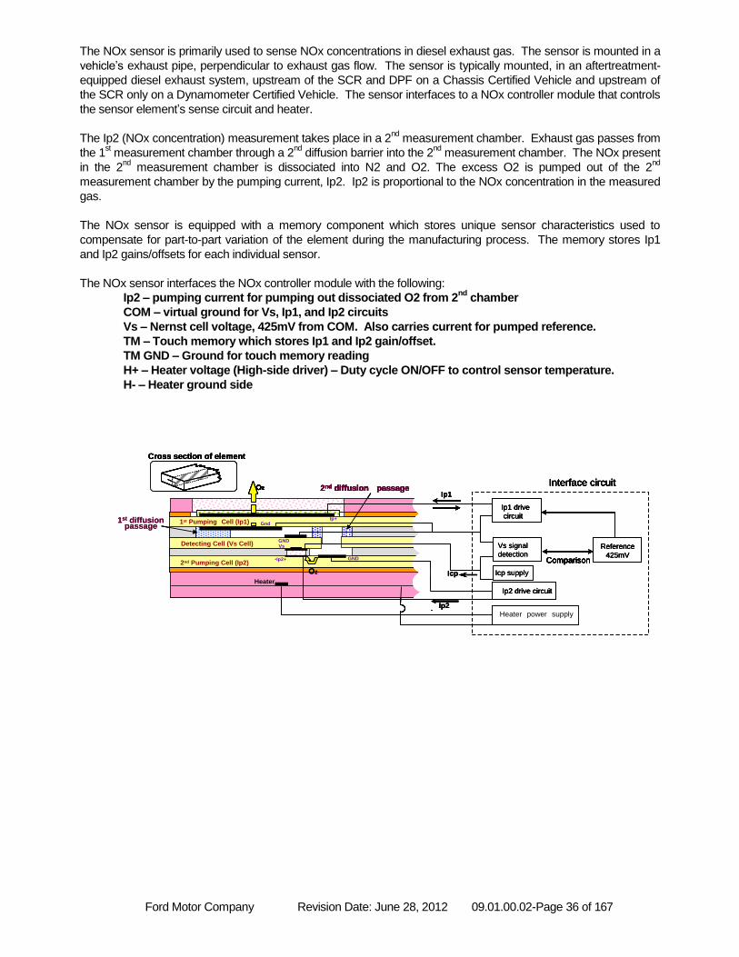
Ford Motor Company Revision Date: June 28, 2012 09.01.00.02-Page 36 of 167
The NOx sensor is primarily used to sense NOx concentrations in diesel exhaust gas. The sensor is mounted in a
vehicle’s exhaust pipe, perpendicular to exhaust gas flow. The sensor is typically mounted, in an aftertreatment-
equipped diesel exhaust system, upstream of the SCR and DPF on a Chassis Certified Vehicle and upstream of
the SCR only on a Dynamometer Certified Vehicle. The sensor interfaces to a NOx controller module that controls
the sensor element’s sense circuit and heater.
The Ip2 (NOx concentration) measurement takes place in a 2nd
measurement chamber. Exhaust gas passes from
the 1st measurement chamber through a 2
nd diffusion barrier into the 2
nd measurement chamber. The NOx present
in the 2nd
measurement chamber is dissociated into N2 and O2. The excess O2 is pumped out of the 2nd
measurement chamber by the pumping current, Ip2. Ip2 is proportional to the NOx concentration in the measured
gas.
The NOx sensor is equipped with a memory component which stores unique sensor characteristics used to
compensate for part-to-part variation of the element during the manufacturing process. The memory stores Ip1
and Ip2 gains/offsets for each individual sensor.
The NOx sensor interfaces the NOx controller module with the following:
Ip2 – pumping current for pumping out dissociated O2 from 2nd
chamber
COM – virtual ground for Vs, Ip1, and Ip2 circuits
Vs – Nernst cell voltage, 425mV from COM. Also carries current for pumped reference.
TM – Touch memory which stores Ip1 and Ip2 gain/offset.
TM GND – Ground for touch memory reading
H+ – Heater voltage (High-side driver) – Duty cycle ON/OFF to control sensor temperature.
H- – Heater ground side
1st diffusionpassage
Cross section of element
Ip1 drive
circuit
Vs signal
detection
Icp supply
Reference
425mVComparison
Interface circuit
Ip2 drive circuit
2nd Pumping Cell (Ip2)
Detecting Cell
2nd diffusion passage
Heater
Ip+Gnd
GNDVs
O2
O2
GND•Ip2+
1st Pumping Cell (Ip1)
Ip1
Icp
Comparison
Heater power supply
Interface circuit
Ip2
2nd Pumping Cell (Ip2)
Detecting Cell (Vs Cell)
2nd diffusion passage
Heater
Ip+Gnd
GNDVs
O2
O2
GND•Ip2+
1st Pumping Cell (Ip1)1st diffusionpassage
Cross section of element
Ip1 drive
circuit
Vs signal
detection
Icp supply
Reference
425mVComparison
Interface circuit
Ip2 drive circuit
2nd Pumping Cell (Ip2)
Detecting Cell
2nd diffusion passage
Heater
Ip+Gnd
GNDVs
O2
O2
GND•Ip2+
1st Pumping Cell (Ip1)
Ip1
Icp
Comparison
Heater power supply
Interface circuit
Ip2
2nd Pumping Cell (Ip2)
Detecting Cell (Vs Cell)
2nd diffusion passage
Heater
Ip+Gnd
GNDVs
O2
O2
GND•Ip2+
1st Pumping Cell (Ip1)
Cross section of elementCross section of element
Ip1 drive
circuit
Ip1 drive
circuit
Vs signal
detection
Icp supply
Reference
425mV
Reference
425mVComparison
Interface circuit
Ip2 drive circuitIp2 drive circuit
2nd Pumping Cell (Ip2)
Detecting Cell
2nd diffusion passage
Heater
Ip+Gnd
GNDVs
O2O2
O2O2
GND•Ip2+
1st Pumping Cell (Ip1)
Ip1
Icp
Comparison
Heater power supply
Interface circuit
Ip2
2nd Pumping Cell (Ip2)
Detecting Cell (Vs Cell)
2nd diffusion passage
Heater
Ip+Gnd
GNDVs
O2O2
O2O2
GND•Ip2+
1st Pumping Cell (Ip1)

Ford Motor Company Revision Date: June 28, 2012 09.01.00.02-Page 37 of 167
IP2 Open (FLO) OBD Algorithm
IP2 Open (FLO) OBD Algorithm
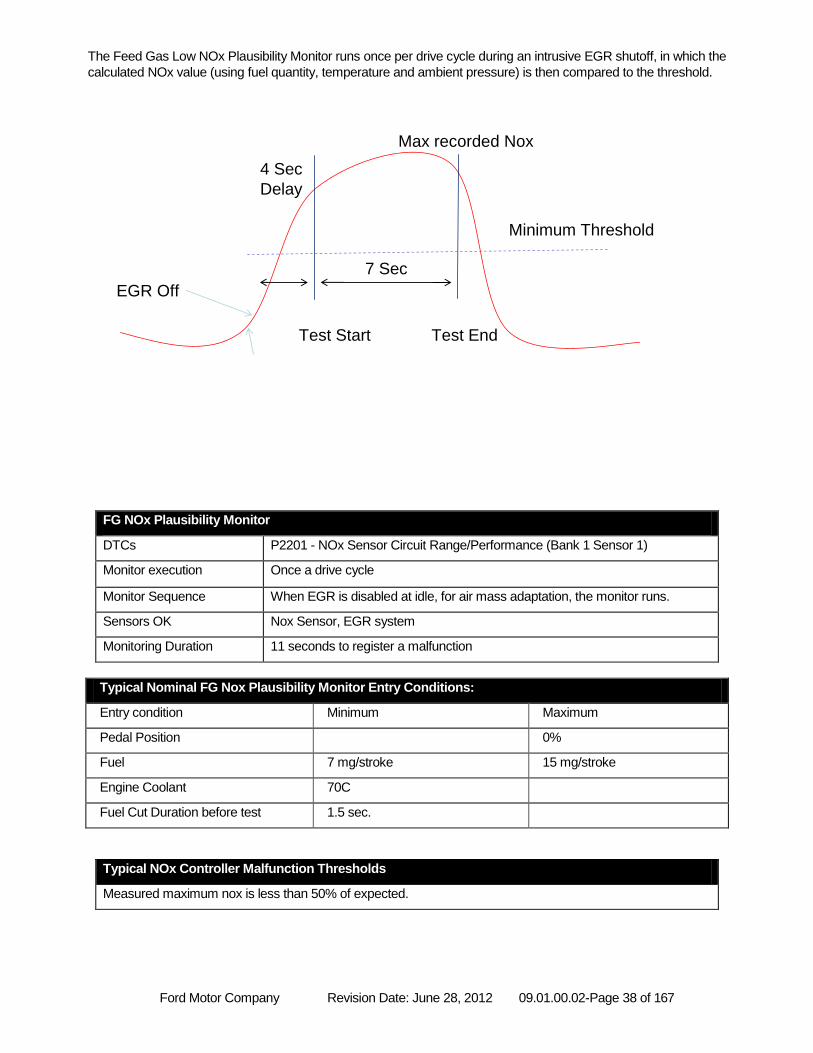
Ford Motor Company Revision Date: June 28, 2012 09.01.00.02-Page 38 of 167
The Feed Gas Low NOx Plausibility Monitor runs once per drive cycle during an intrusive EGR shutoff, in which the
calculated NOx value (using fuel quantity, temperature and ambient pressure) is then compared to the threshold.
FG NOx Plausibility Monitor
DTCs P2201 - NOx Sensor Circuit Range/Performance (Bank 1 Sensor 1)
Monitor execution Once a drive cycle
Monitor Sequence When EGR is disabled at idle, for air mass adaptation, the monitor runs.
Sensors OK Nox Sensor, EGR system
Monitoring Duration 11 seconds to register a malfunction
Typical Nominal FG Nox Plausibility Monitor Entry Conditions:
Entry condition Minimum Maximum
Pedal Position 0%
Fuel 7 mg/stroke 15 mg/stroke
Engine Coolant 70C
Fuel Cut Duration before test 1.5 sec.
Typical NOx Controller Malfunction Thresholds
Measured maximum nox is less than 50% of expected.
Entry Conditions met
EGR Off
Test Start Test End
Max recorded Nox
Minimum Threshold
RPM – idle speed
Pedal = 0
Fuel 7<>15 mg/stroke
Coolant > 70C
7 Sec
1.5 Sec fuel cut before idle
1 per drive cycle
2 trip MIL
50% of expected for threshold
4 Sec
Delay
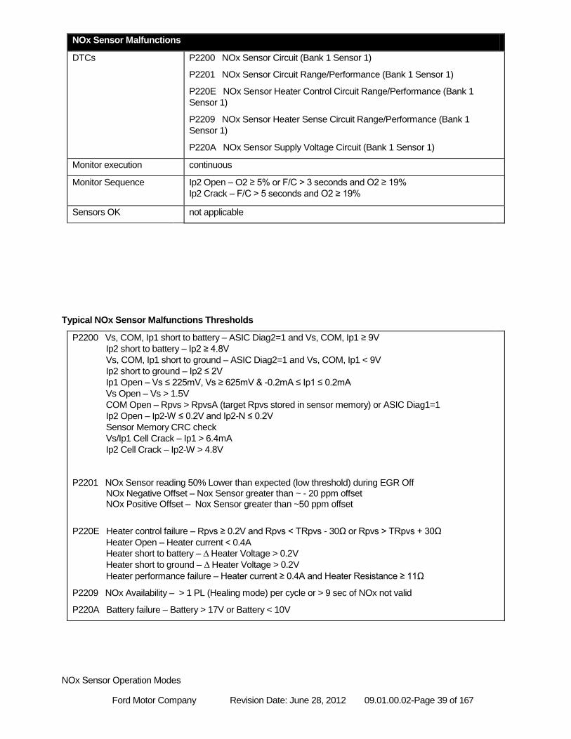
Ford Motor Company Revision Date: June 28, 2012 09.01.00.02-Page 39 of 167
NOx Sensor Malfunctions
DTCs P2200 NOx Sensor Circuit (Bank 1 Sensor 1)
P2201 NOx Sensor Circuit Range/Performance (Bank 1 Sensor 1)
P220E NOx Sensor Heater Control Circuit Range/Performance (Bank 1
Sensor 1)
P2209 NOx Sensor Heater Sense Circuit Range/Performance (Bank 1
Sensor 1)
P220A NOx Sensor Supply Voltage Circuit (Bank 1 Sensor 1)
Monitor execution continuous
Monitor Sequence Ip2 Open – O2 ≥ 5% or F/C > 3 seconds and O2 ≥ 19%
Ip2 Crack – F/C > 5 seconds and O2 ≥ 19%
Sensors OK not applicable
Typical NOx Sensor Malfunctions Thresholds
P2200 Vs, COM, Ip1 short to battery – ASIC Diag2=1 and Vs, COM, Ip1 ≥ 9V
Ip2 short to battery – Ip2 ≥ 4.8V
Vs, COM, Ip1 short to ground – ASIC Diag2=1 and Vs, COM, Ip1 < 9V
Ip2 short to ground – Ip2 ≤ 2V
Ip1 Open – Vs ≤ 225mV, Vs ≥ 625mV & -0.2mA ≤ Ip1 ≤ 0.2mA
Vs Open – Vs > 1.5V
COM Open – Rpvs > RpvsA (target Rpvs stored in sensor memory) or ASIC Diag1=1
Ip2 Open – Ip2-W ≤ 0.2V and Ip2-N ≤ 0.2V
Sensor Memory CRC check
Vs/Ip1 Cell Crack – Ip1 > 6.4mA
Ip2 Cell Crack – Ip2-W > 4.8V
P2201 NOx Sensor reading 50% Lower than expected (low threshold) during EGR Off NOx Negative Offset – Nox Sensor greater than ~ - 20 ppm offset NOx Positive Offset – Nox Sensor greater than ~50 ppm offset
P220E Heater control failure – Rpvs ≥ 0.2V and Rpvs < TRpvs - 30Ω or Rpvs > TRpvs + 30Ω
Heater Open – Heater current < 0.4A
Heater short to battery – Δ Heater Voltage > 0.2V
Heater short to ground – Δ Heater Voltage > 0.2V
Heater performance failure – Heater current ≥ 0.4A and Heater Resistance ≥ 11Ω
P2209 NOx Availability – > 1 PL (Healing mode) per cycle or > 9 sec of NOx not valid
P220A Battery failure – Battery > 17V or Battery < 10V
NOx Sensor Operation Modes
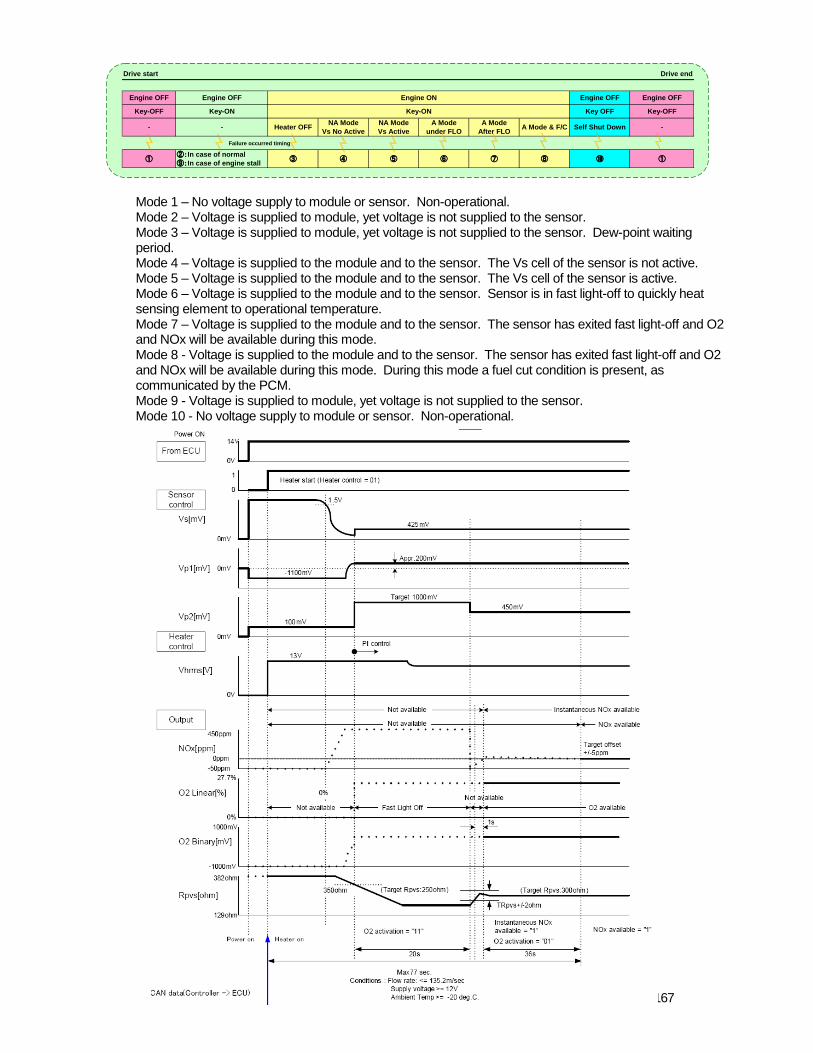
Ford Motor Company Revision Date: June 28, 2012 09.01.00.02-Page 40 of 167
Mode 1 – No voltage supply to module or sensor. Non-operational. Mode 2 – Voltage is supplied to module, yet voltage is not supplied to the sensor. Mode 3 – Voltage is supplied to module, yet voltage is not supplied to the sensor. Dew-point waiting period. Mode 4 – Voltage is supplied to the module and to the sensor. The Vs cell of the sensor is not active. Mode 5 – Voltage is supplied to the module and to the sensor. The Vs cell of the sensor is active. Mode 6 – Voltage is supplied to the module and to the sensor. Sensor is in fast light-off to quickly heat sensing element to operational temperature. Mode 7 – Voltage is supplied to the module and to the sensor. The sensor has exited fast light-off and O2 and NOx will be available during this mode. Mode 8 - Voltage is supplied to the module and to the sensor. The sensor has exited fast light-off and O2 and NOx will be available during this mode. During this mode a fuel cut condition is present, as communicated by the PCM. Mode 9 - Voltage is supplied to module, yet voltage is not supplied to the sensor. Mode 10 - No voltage supply to module or sensor. Non-operational.
Drive end
-
Engine OFF
Key OFF
Engine OFF
Key-OFF
Self Shut Down
①⑩⑦ ⑧
Drive start
Engine OFF
Key-OFF
-
①
A Mode & F/CA Mode
After FLO
Engine OFF
Key-ON
-
Engine ON
Key-ON
②:In case of normal
⑨:In case of engine stall
Heater OFF
③
A Mode
under FLO
⑥
NA Mode
Vs No Active
④
NA Mode
Vs Active
⑤
Failure occurred timing
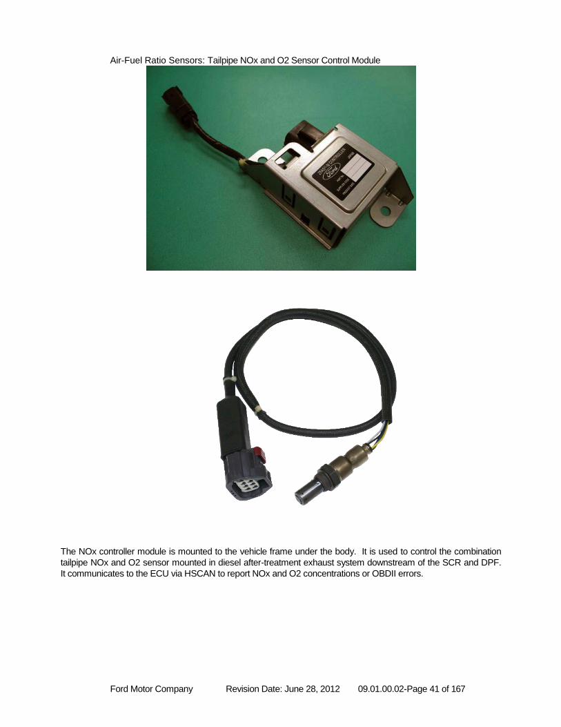
Ford Motor Company Revision Date: June 28, 2012 09.01.00.02-Page 41 of 167
Air-Fuel Ratio Sensors: Tailpipe NOx and O2 Sensor Control Module
The NOx controller module is mounted to the vehicle frame under the body. It is used to control the combination
tailpipe NOx and O2 sensor mounted in diesel after-treatment exhaust system downstream of the SCR and DPF.
It communicates to the ECU via HSCAN to report NOx and O2 concentrations or OBDII errors.
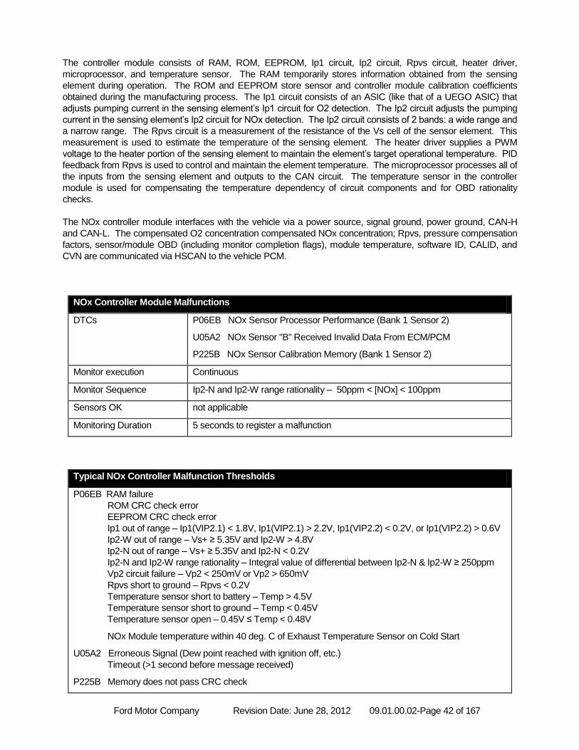
Ford Motor Company Revision Date: June 28, 2012 09.01.00.02-Page 42 of 167
The controller module consists of RAM, ROM, EEPROM, Ip1 circuit, Ip2 circuit, Rpvs circuit, heater driver,
microprocessor, and temperature sensor. The RAM temporarily stores information obtained from the sensing
element during operation. The ROM and EEPROM store sensor and controller module calibration coefficients
obtained during the manufacturing process. The Ip1 circuit consists of an ASIC (like that of a UEGO ASIC) that
adjusts pumping current in the sensing element’s Ip1 circuit for O2 detection. The Ip2 circuit adjusts the pumping
current in the sensing element’s Ip2 circuit for NOx detection. The Ip2 circuit consists of 2 bands: a wide range and
a narrow range. The Rpvs circuit is a measurement of the resistance of the Vs cell of the sensor element. This
measurement is used to estimate the temperature of the sensing element. The heater driver supplies a PWM
voltage to the heater portion of the sensing element to maintain the element’s target operational temperature. PID
feedback from Rpvs is used to control and maintain the element temperature. The microprocessor processes all of
the inputs from the sensing element and outputs to the CAN circuit. The temperature sensor in the controller
module is used for compensating the temperature dependency of circuit components and for OBD rationality
checks.
The NOx controller module interfaces with the vehicle via a power source, signal ground, power ground, CAN-H
and CAN-L. The compensated O2 concentration compensated NOx concentration; Rpvs, pressure compensation
factors, sensor/module OBD (including monitor completion flags), module temperature, software ID, CALID, and
CVN are communicated via HSCAN to the vehicle PCM.
NOx Controller Module Malfunctions
DTCs P06EB NOx Sensor Processor Performance (Bank 1 Sensor 2)
U05A2 NOx Sensor "B" Received Invalid Data From ECM/PCM
P225B NOx Sensor Calibration Memory (Bank 1 Sensor 2)
Monitor execution Continuous
Monitor Sequence Ip2-N and Ip2-W range rationality – 50ppm < [NOx] < 100ppm
Sensors OK not applicable
Monitoring Duration 5 seconds to register a malfunction
Typical NOx Controller Malfunction Thresholds
P06EB RAM failure
ROM CRC check error
EEPROM CRC check error
Ip1 out of range – Ip1(VIP2.1) < 1.8V, Ip1(VIP2.1) > 2.2V, Ip1(VIP2.2) < 0.2V, or Ip1(VIP2.2) > 0.6V
Ip2-W out of range – Vs+ ≥ 5.35V and Ip2-W > 4.8V
Ip2-N out of range – Vs+ ≥ 5.35V and Ip2-N < 0.2V
Ip2-N and Ip2-W range rationality – Integral value of differential between Ip2-N & Ip2-W ≥ 250ppm
Vp2 circuit failure – Vp2 < 250mV or Vp2 > 650mV
Rpvs short to ground – Rpvs < 0.2V
Temperature sensor short to battery – Temp > 4.5V
Temperature sensor short to ground – Temp < 0.45V
Temperature sensor open – 0.45V ≤ Temp < 0.48V
NOx Module temperature within 40 deg. C of Exhaust Temperature Sensor on Cold Start
U05A2 Erroneous Signal (Dew point reached with ignition off, etc.)
Timeout (>1 second before message received)
P225B Memory does not pass CRC check
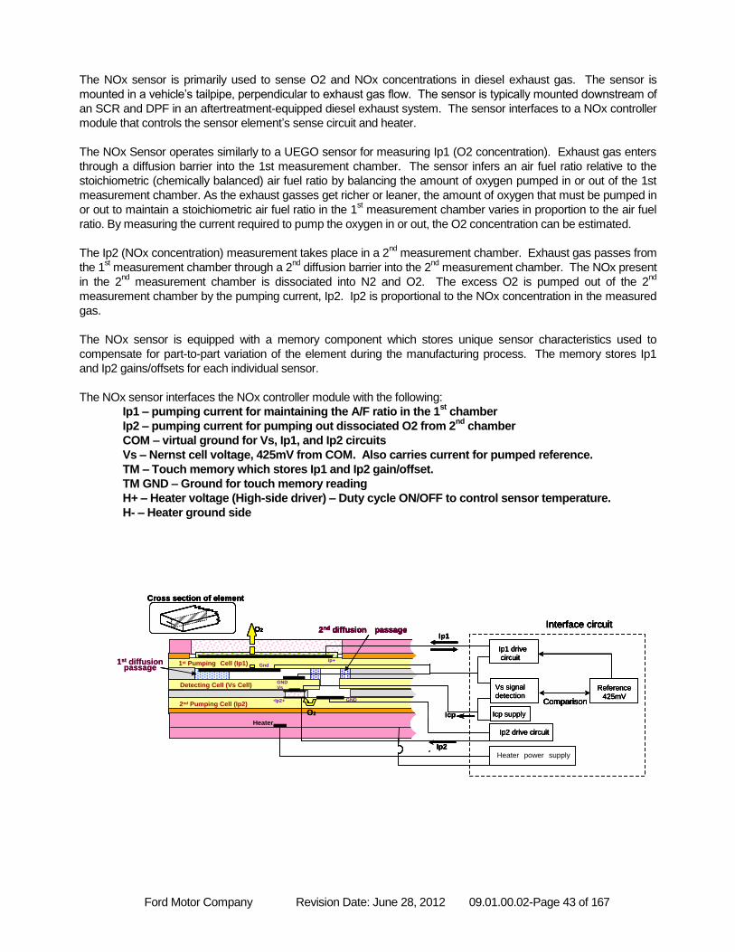
Ford Motor Company Revision Date: June 28, 2012 09.01.00.02-Page 43 of 167
The NOx sensor is primarily used to sense O2 and NOx concentrations in diesel exhaust gas. The sensor is
mounted in a vehicle’s tailpipe, perpendicular to exhaust gas flow. The sensor is typically mounted downstream of
an SCR and DPF in an aftertreatment-equipped diesel exhaust system. The sensor interfaces to a NOx controller
module that controls the sensor element’s sense circuit and heater.
The NOx Sensor operates similarly to a UEGO sensor for measuring Ip1 (O2 concentration). Exhaust gas enters
through a diffusion barrier into the 1st measurement chamber. The sensor infers an air fuel ratio relative to the
stoichiometric (chemically balanced) air fuel ratio by balancing the amount of oxygen pumped in or out of the 1st
measurement chamber. As the exhaust gasses get richer or leaner, the amount of oxygen that must be pumped in
or out to maintain a stoichiometric air fuel ratio in the 1st measurement chamber varies in proportion to the air fuel
ratio. By measuring the current required to pump the oxygen in or out, the O2 concentration can be estimated.
The Ip2 (NOx concentration) measurement takes place in a 2nd
measurement chamber. Exhaust gas passes from
the 1st measurement chamber through a 2
nd diffusion barrier into the 2
nd measurement chamber. The NOx present
in the 2nd
measurement chamber is dissociated into N2 and O2. The excess O2 is pumped out of the 2nd
measurement chamber by the pumping current, Ip2. Ip2 is proportional to the NOx concentration in the measured
gas.
The NOx sensor is equipped with a memory component which stores unique sensor characteristics used to
compensate for part-to-part variation of the element during the manufacturing process. The memory stores Ip1
and Ip2 gains/offsets for each individual sensor.
The NOx sensor interfaces the NOx controller module with the following:
Ip1 – pumping current for maintaining the A/F ratio in the 1st chamber
Ip2 – pumping current for pumping out dissociated O2 from 2nd
chamber
COM – virtual ground for Vs, Ip1, and Ip2 circuits
Vs – Nernst cell voltage, 425mV from COM. Also carries current for pumped reference.
TM – Touch memory which stores Ip1 and Ip2 gain/offset.
TM GND – Ground for touch memory reading
H+ – Heater voltage (High-side driver) – Duty cycle ON/OFF to control sensor temperature.
H- – Heater ground side
1st diffusionpassage
Cross section of element
Ip1 drive
circuit
Vs signal
detection
Icp supply
Reference
425mVComparison
Interface circuit
Ip2 drive circuit
2nd Pumping Cell (Ip2)
Detecting Cell
2nd diffusion passage
Heater
Ip+Gnd
GNDVs
O2
O2
GND•Ip2+
1st Pumping Cell (Ip1)
Ip1
Icp
Comparison
Heater power supply
Interface circuit
Ip2
2nd Pumping Cell (Ip2)
Detecting Cell (Vs Cell)
2nd diffusion passage
Heater
Ip+Gnd
GNDVs
O2
O2
GND•Ip2+
1st Pumping Cell (Ip1)1st diffusionpassage
Cross section of element
Ip1 drive
circuit
Vs signal
detection
Icp supply
Reference
425mVComparison
Interface circuit
Ip2 drive circuit
2nd Pumping Cell (Ip2)
Detecting Cell
2nd diffusion passage
Heater
Ip+Gnd
GNDVs
O2
O2
GND•Ip2+
1st Pumping Cell (Ip1)
Ip1
Icp
Comparison
Heater power supply
Interface circuit
Ip2
2nd Pumping Cell (Ip2)
Detecting Cell (Vs Cell)
2nd diffusion passage
Heater
Ip+Gnd
GNDVs
O2
O2
GND•Ip2+
1st Pumping Cell (Ip1)
Cross section of elementCross section of element
Ip1 drive
circuit
Ip1 drive
circuit
Vs signal
detection
Icp supply
Reference
425mV
Reference
425mVComparison
Interface circuit
Ip2 drive circuitIp2 drive circuit
2nd Pumping Cell (Ip2)
Detecting Cell
2nd diffusion passage
Heater
Ip+Gnd
GNDVs
O2O2
O2O2
GND•Ip2+
1st Pumping Cell (Ip1)
Ip1
Icp
Comparison
Heater power supply
Interface circuit
Ip2
2nd Pumping Cell (Ip2)
Detecting Cell (Vs Cell)
2nd diffusion passage
Heater
Ip+Gnd
GNDVs
O2O2
O2O2
GND•Ip2+
1st Pumping Cell (Ip1)
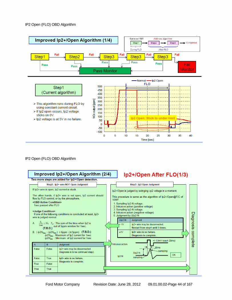
Ford Motor Company Revision Date: June 28, 2012 09.01.00.02-Page 44 of 167
IP2 Open (FLO) OBD Algorithm
IP2 Open (FLO) OBD Algorithm
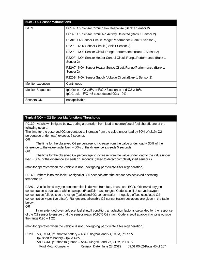
Ford Motor Company Revision Date: June 28, 2012 09.01.00.02-Page 45 of 167
NOx – O2 Sensor Malfunctions
DTCs P0139 O2 Sensor Circuit Slow Response (Bank 1 Sensor 2)
P0140 O2 Sensor Circuit No Activity Detected (Bank 1 Sensor 2)
P2A01 O2 Sensor Circuit Range/Performance (Bank 1 Sensor 2)
P229E NOx Sensor Circuit (Bank 1 Sensor 2)
P229F NOx Sensor Circuit Range/Performance (Bank 1 Sensor 2)
P220F NOx Sensor Heater Control Circuit Range/Performance (Bank 1
Sensor 2)
P22A7 NOx Sensor Heater Sense Circuit Range/Performance (Bank 1
Sensor 2)
P220B NOx Sensor Supply Voltage Circuit (Bank 1 Sensor 2)
Monitor execution Continuous
Monitor Sequence Ip2 Open – 02 ≥ 5% or F/C > 3 seconds and O2 ≥ 19%
Ip2 Crack – F/C > 5 seconds and O2 ≥ 19%
Sensors OK not applicable
Typical NOx – O2 Sensor Malfunctions Thresholds
P0139 As shown in figure below, during a transition from load to overrun/decel fuel shutoff, one of the
following occurs:
The time for the observed O2 percentage to increase from the value under load by 30% of (21%-O2
percentage under load) exceeds 6 seconds
OR
The time for the observed O2 percentage to increase from the value under load + 30% of the
difference to the value under load + 60% of the difference exceeds 5 seconds
OR
The time for the observed O2 percentage to increase from the value under load to the value under
load + 60% of the difference exceeds 11 seconds. (Used to detect completely inert sensors.)
(monitor operates when the vehicle is not undergoing particulate filter regeneration)
P0140 If there is no available O2 signal at 300 seconds after the sensor has achieved operating
temperature
P2A01 A calculated oxygen concentration is derived from fuel, boost, and EGR. Observed oxygen
concentration is evaluated within two speed/load/air mass ranges. Code is set if observed oxygen
concentration falls outside the range ((calculated O2 concentration – negative offset, calculated O2
concentration + positive offset). Ranges and allowable O2 concentration deviations are given in the table
below.
OR
In an extended overrun/decel fuel shutoff condition, an adaption factor is calculated for the response
of the O2 sensor to ensure that the sensor reads 20.95% O2 in air. Code is set if adaption factor is outside
the range 0.95 – 1.22.
(monitor operates when the vehicle is not undergoing particulate filter regeneration)
P229E Vs, COM, Ip1 short to battery – ASIC Diag2=1 and Vs, COM, Ip1 ≥ 9V
Ip2 short to battery – Ip2 ≥ 4.8V
Vs, COM, Ip1 short to ground – ASIC Diag2=1 and Vs, COM, Ip1 < 9V
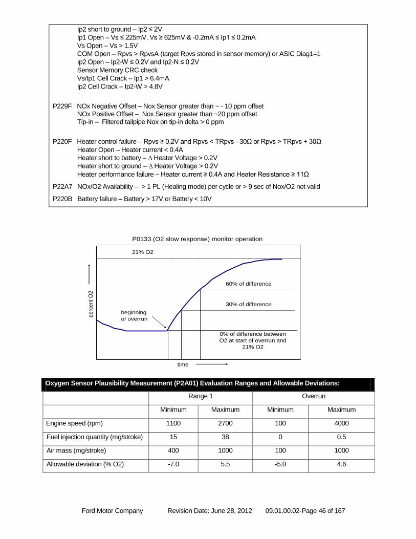
Ford Motor Company Revision Date: June 28, 2012 09.01.00.02-Page 46 of 167
Ip2 short to ground – Ip2 ≤ 2V
Ip1 Open – Vs ≤ 225mV, Vs ≥ 625mV & -0.2mA ≤ Ip1 ≤ 0.2mA
Vs Open – Vs > 1.5V
COM Open – Rpvs > RpvsA (target Rpvs stored in sensor memory) or ASIC Diag1=1
Ip2 Open – Ip2-W ≤ 0.2V and Ip2-N ≤ 0.2V
Sensor Memory CRC check
Vs/Ip1 Cell Crack – Ip1 > 6.4mA
Ip2 Cell Crack – Ip2-W > 4.8V
P229F NOx Negative Offset – Nox Sensor greater than ~ - 10 ppm offset
NOx Positive Offset – Nox Sensor greater than ~20 ppm offset Tip-in – Filtered tailpipe Nox on tip-in delta > 0 ppm
P220F Heater control failure – Rpvs ≥ 0.2V and Rpvs < TRpvs - 30Ω or Rpvs > TRpvs + 30Ω
Heater Open – Heater current < 0.4A
Heater short to battery – Δ Heater Voltage > 0.2V
Heater short to ground – Δ Heater Voltage > 0.2V
Heater performance failure – Heater current ≥ 0.4A and Heater Resistance ≥ 11Ω
P22A7 NOx/O2 Availability – > 1 PL (Healing mode) per cycle or > 9 sec of Nox/O2 not valid
P220B Battery failure – Battery > 17V or Battery < 10V
Oxygen Sensor Plausibility Measurement (P2A01) Evaluation Ranges and Allowable Deviations:
Range 1 Overrun
Minimum Maximum Minimum Maximum
Engine speed (rpm) 1100 2700 100 4000
Fuel injection quantity (mg/stroke) 15 38 0 0.5
Air mass (mg/stroke) 400 1000 100 1000
Allowable deviation (% O2) -7.0 5.5 -5.0 4.6
perc
ent
O2
time
21% O2
0% of difference between
O2 at start of overrun and
21% O2
30% of difference
60% of difference
beginning
of overrun
P0133 (O2 slow response) monitor operation
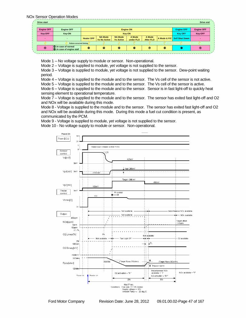
Ford Motor Company Revision Date: June 28, 2012 09.01.00.02-Page 47 of 167
NOx Sensor Operation Modes
Mode 1 – No voltage supply to module or sensor. Non-operational. Mode 2 – Voltage is supplied to module, yet voltage is not supplied to the sensor. Mode 3 – Voltage is supplied to module, yet voltage is not supplied to the sensor. Dew-point waiting period. Mode 4 – Voltage is supplied to the module and to the sensor. The Vs cell of the sensor is not active. Mode 5 – Voltage is supplied to the module and to the sensor. The Vs cell of the sensor is active. Mode 6 – Voltage is supplied to the module and to the sensor. Sensor is in fast light-off to quickly heat sensing element to operational temperature. Mode 7 – Voltage is supplied to the module and to the sensor. The sensor has exited fast light-off and O2 and NOx will be available during this mode. Mode 8 - Voltage is supplied to the module and to the sensor. The sensor has exited fast light-off and O2 and NOx will be available during this mode. During this mode a fuel cut condition is present, as communicated by the PCM. Mode 9 - Voltage is supplied to module, yet voltage is not supplied to the sensor. Mode 10 - No voltage supply to module or sensor. Non-operational.
Drive end
-
Engine OFF
Key OFF
Engine OFF
Key-OFF
Self Shut Down
①⑩⑦ ⑧
Drive start
Engine OFF
Key-OFF
-
①
A Mode & F/CA Mode
After FLO
Engine OFF
Key-ON
-
Engine ON
Key-ON
②:In case of normal
⑨:In case of engine stall
Heater OFF
③
A Mode
under FLO
⑥
NA Mode
Vs No Active
④
NA Mode
Vs Active
⑤
Failure occurred timing
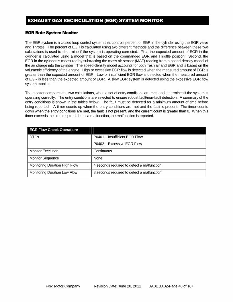
Ford Motor Company Revision Date: June 28, 2012 09.01.00.02-Page 48 of 167
EXHAUST GAS RECIRCULATION (EGR) SYSTEM MONITOR
EGR Rate System Monitor
The EGR system is a closed loop control system that controls percent of EGR in the cylinder using the EGR valve
and Throttle. The percent of EGR is calculated using two different methods and the difference between these two
calculations is used to determine if the system is operating corrected. First, the expected amount of EGR in the
cylinder is calculated using a model that is based on the commanded EGR and Throttle position. Second, the
EGR in the cylinder is measured by subtracting the mass air sensor (MAF) reading from a speed-density model of
the air charge into the cylinder. The speed-density model accounts for both fresh air and EGR and is based on the
volumetric efficiency of the engine. High or excessive EGR flow is detected when the measured amount of EGR is
greater than the expected amount of EGR. Low or insufficient EGR flow is detected when the measured amount
of EGR is less than the expected amount of EGR. A slow EGR system is detected using the excessive EGR flow
system monitor.
The monitor compares the two calculations, when a set of entry conditions are met, and determines if the system is
operating correctly. The entry conditions are selected to ensure robust fault/non-fault detection. A summary of the
entry conditions is shown in the tables below. The fault must be detected for a minimum amount of time before
being reported. A timer counts up when the entry conditions are met and the fault is present. The timer counts
down when the entry conditions are met, the fault is not present, and the current count is greater than 0. When this
timer exceeds the time required detect a malfunction, the malfunction is reported.
EGR Flow Check Operation:
DTCs P0401 – Insufficient EGR Flow
P0402 – Excessive EGR Flow
Monitor Execution Continuous
Monitor Sequence None
Monitoring Duration High Flow 4 seconds required to detect a malfunction
Monitoring Duration Low Flow 8 seconds required to detect a malfunction
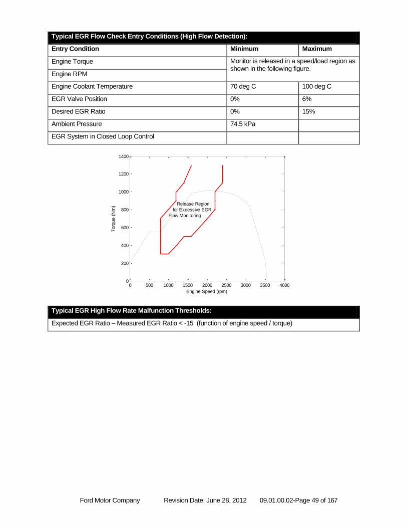
Ford Motor Company Revision Date: June 28, 2012 09.01.00.02-Page 49 of 167
Typical EGR Flow Check Entry Conditions (High Flow Detection):
Entry Condition Minimum Maximum
Engine Torque Monitor is released in a speed/load region as shown in the following figure.
Engine RPM
Engine Coolant Temperature 70 deg C 100 deg C
EGR Valve Position 0% 6%
Desired EGR Ratio 0% 15%
Ambient Pressure 74.5 kPa
EGR System in Closed Loop Control
Typical EGR High Flow Rate Malfunction Thresholds:
Expected EGR Ratio – Measured EGR Ratio < -15 (function of engine speed / torque)
0 500 1000 1500 2000 2500 3000 3500 40000
200
400
600
800
1000
1200
1400
Engine Speed (rpm)
Torq
ue (
Nm
) Release Region
for Excessive EGR
Flow Monitoring
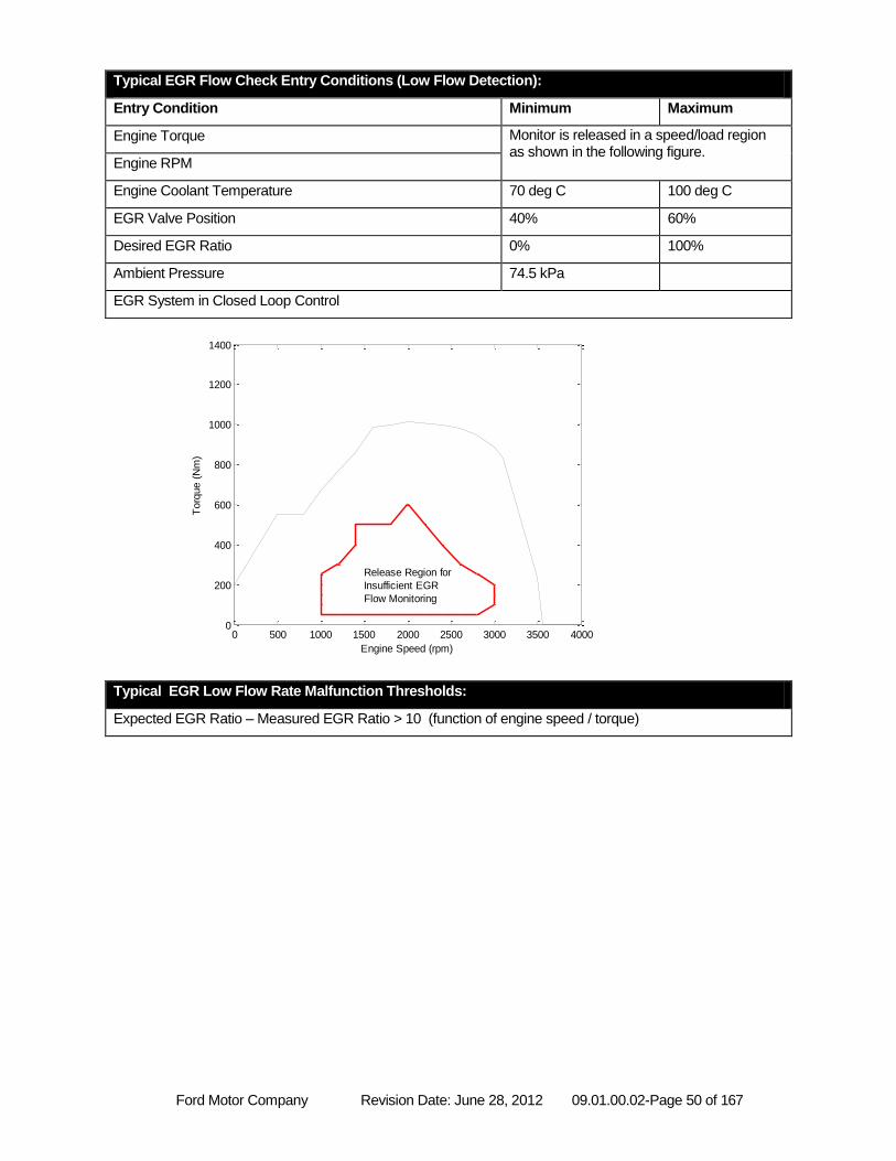
Ford Motor Company Revision Date: June 28, 2012 09.01.00.02-Page 50 of 167
Typical EGR Flow Check Entry Conditions (Low Flow Detection):
Entry Condition Minimum Maximum
Engine Torque Monitor is released in a speed/load region as shown in the following figure.
Engine RPM
Engine Coolant Temperature 70 deg C 100 deg C
EGR Valve Position 40% 60%
Desired EGR Ratio 0% 100%
Ambient Pressure 74.5 kPa
EGR System in Closed Loop Control
Typical EGR Low Flow Rate Malfunction Thresholds:
Expected EGR Ratio – Measured EGR Ratio > 10 (function of engine speed / torque)
0 500 1000 1500 2000 2500 3000 3500 40000
200
400
600
800
1000
1200
1400
Engine Speed (rpm)
Torq
ue (
Nm
)
Release Region for
Insufficient EGR
Flow Monitoring
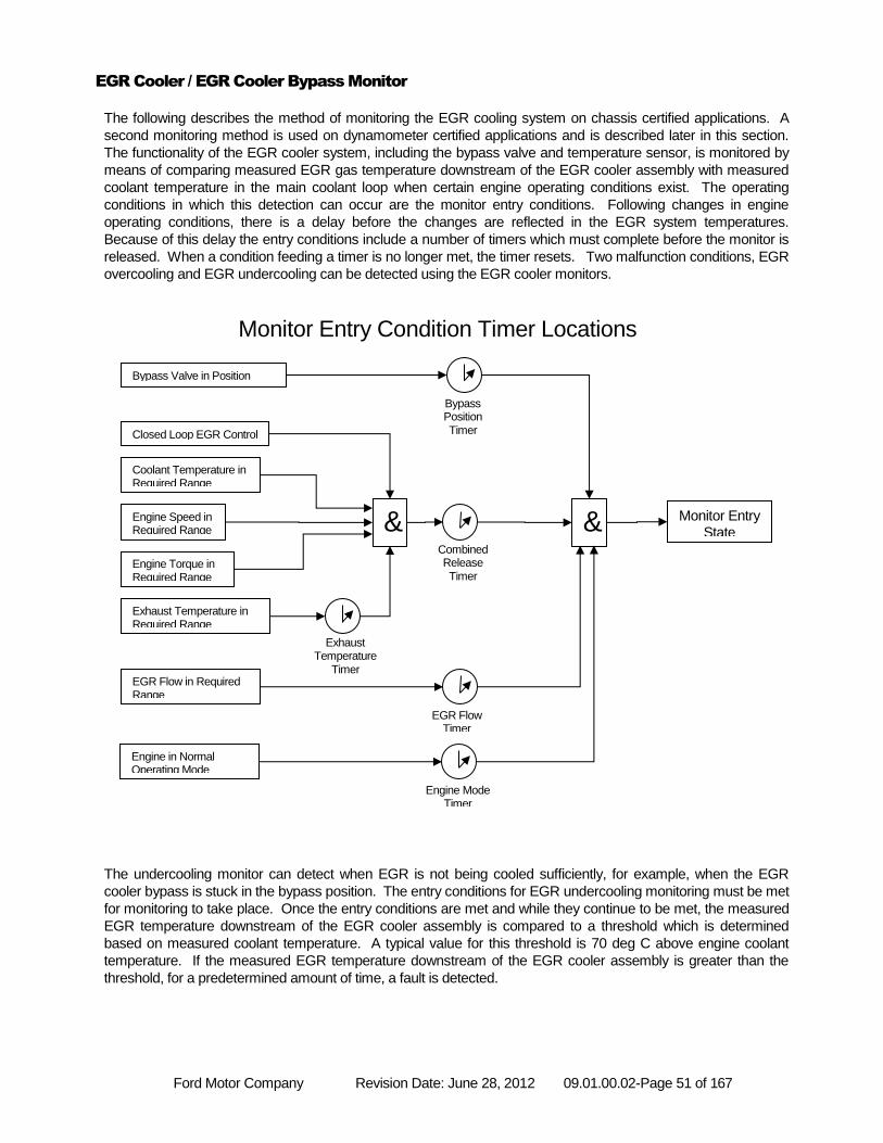
Ford Motor Company Revision Date: June 28, 2012 09.01.00.02-Page 51 of 167
EGR Cooler / EGR Cooler Bypass Monitor
The following describes the method of monitoring the EGR cooling system on chassis certified applications. A
second monitoring method is used on dynamometer certified applications and is described later in this section.
The functionality of the EGR cooler system, including the bypass valve and temperature sensor, is monitored by
means of comparing measured EGR gas temperature downstream of the EGR cooler assembly with measured
coolant temperature in the main coolant loop when certain engine operating conditions exist. The operating
conditions in which this detection can occur are the monitor entry conditions. Following changes in engine
operating conditions, there is a delay before the changes are reflected in the EGR system temperatures.
Because of this delay the entry conditions include a number of timers which must complete before the monitor is
released. When a condition feeding a timer is no longer met, the timer resets. Two malfunction conditions, EGR
overcooling and EGR undercooling can be detected using the EGR cooler monitors.
The undercooling monitor can detect when EGR is not being cooled sufficiently, for example, when the EGR
cooler bypass is stuck in the bypass position. The entry conditions for EGR undercooling monitoring must be met
for monitoring to take place. Once the entry conditions are met and while they continue to be met, the measured
EGR temperature downstream of the EGR cooler assembly is compared to a threshold which is determined
based on measured coolant temperature. A typical value for this threshold is 70 deg C above engine coolant
temperature. If the measured EGR temperature downstream of the EGR cooler assembly is greater than the
threshold, for a predetermined amount of time, a fault is detected.
Bypass Valve in Position
Closed Loop EGR Control
Coolant Temperature in Required Range
Engine Speed in Required Range
Engine Torque in Required Range
Exhaust Temperature in Required Range
EGR Flow in Required Range
& & Monitor Entry State
Exhaust Temperature
Timer
EGR Flow Timer
Combined Release Timer
Bypass Position Timer
Monitor Entry Condition Timer Locations
Engine in Normal Operating Mode
Engine Mode Timer
Ford Motor Company Revision Date: June 28, 2012 09.01.00.02-Page 52 of 167
EGR Cooler (Undercooling) Monitor:
DTCs P2457 – EGR Cooler Performance
Monitor execution Once per driving cycle , once entry conditions are met
Monitor Sequence None
Monitoring Duration 12 seconds to detected a malfunction
EGR Cooler/ECB Entry Conditions (Undercooling):
Entry Condition Minimum Maximum
EGR Cooler Bypass Valve Command Cooling Position
EGR System in Closed-Loop Control
Engine Coolant Temperature 70 deg C 130 deg C
Engine Speed 1100 rpm 3500 rpm
Engine Torque 200 Nm 1400 Nm
Exhaust Temperature 0 deg C 800 deg C
EGR Flow 0 g/s 42 g/s
Engine Operating Mode Normal
EGR Cooler/ECB Entry Timers (Undercooling):
Timer Minimum Time
Bypass Position Timer 5 sec
Combined Release Timer 1 sec
Exhaust Temperature Timer 5 sec
EGR Flow Timer 5 sec
Engine Mode Timer 100 sec
Typical Undercooling Malfunction Thresholds:
Measured EGR temperature downstream of the EGR cooler assembly > Coolant Temperature + 70
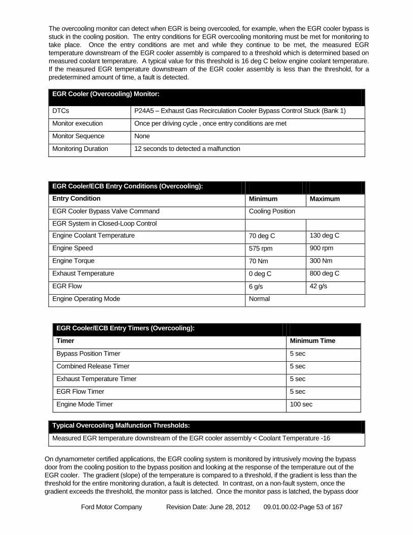
Ford Motor Company Revision Date: June 28, 2012 09.01.00.02-Page 53 of 167
The overcooling monitor can detect when EGR is being overcooled, for example, when the EGR cooler bypass is
stuck in the cooling position. The entry conditions for EGR overcooling monitoring must be met for monitoring to
take place. Once the entry conditions are met and while they continue to be met, the measured EGR
temperature downstream of the EGR cooler assembly is compared to a threshold which is determined based on
measured coolant temperature. A typical value for this threshold is 16 deg C below engine coolant temperature.
If the measured EGR temperature downstream of the EGR cooler assembly is less than the threshold, for a
predetermined amount of time, a fault is detected.
EGR Cooler (Overcooling) Monitor:
DTCs P24A5 – Exhaust Gas Recirculation Cooler Bypass Control Stuck (Bank 1)
Monitor execution Once per driving cycle , once entry conditions are met
Monitor Sequence None
Monitoring Duration 12 seconds to detected a malfunction
EGR Cooler/ECB Entry Conditions (Overcooling):
Entry Condition Minimum Maximum
EGR Cooler Bypass Valve Command Cooling Position
EGR System in Closed-Loop Control
Engine Coolant Temperature 70 deg C 130 deg C
Engine Speed 575 rpm 900 rpm
Engine Torque 70 Nm 300 Nm
Exhaust Temperature 0 deg C 800 deg C
EGR Flow 6 g/s 42 g/s
Engine Operating Mode Normal
EGR Cooler/ECB Entry Timers (Overcooling):
Timer Minimum Time
Bypass Position Timer 5 sec
Combined Release Timer 5 sec
Exhaust Temperature Timer 5 sec
EGR Flow Timer 5 sec
Engine Mode Timer 100 sec
Typical Overcooling Malfunction Thresholds:
Measured EGR temperature downstream of the EGR cooler assembly < Coolant Temperature -16
On dynamometer certified applications, the EGR cooling system is monitored by intrusively moving the bypass
door from the cooling position to the bypass position and looking at the response of the temperature out of the
EGR cooler. The gradient (slope) of the temperature is compared to a threshold, if the gradient is less than the
threshold for the entire monitoring duration, a fault is detected. In contrast, on a non-fault system, once the
gradient exceeds the threshold, the monitor pass is latched. Once the monitor pass is latched, the bypass door
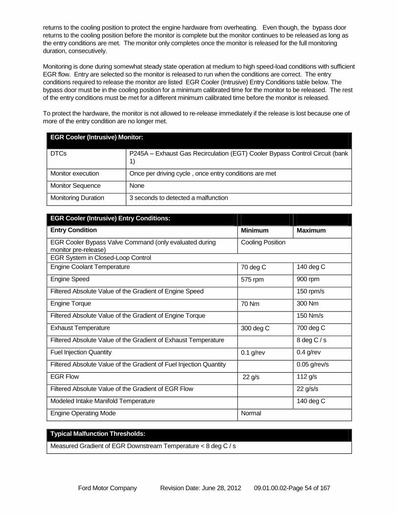
Ford Motor Company Revision Date: June 28, 2012 09.01.00.02-Page 54 of 167
returns to the cooling position to protect the engine hardware from overheating. Even though, the bypass door
returns to the cooling position before the monitor is complete but the monitor continues to be released as long as
the entry conditions are met. The monitor only completes once the monitor is released for the full monitoring
duration, consecutively.
Monitoring is done during somewhat steady state operation at medium to high speed-load conditions with sufficient
EGR flow. Entry are selected so the monitor is released to run when the conditions are correct. The entry
conditions required to release the monitor are listed EGR Cooler (Intrusive) Entry Conditions table below. The
bypass door must be in the cooling position for a minimum calibrated time for the monitor to be released. The rest
of the entry conditions must be met for a different minimum calibrated time before the monitor is released.
To protect the hardware, the monitor is not allowed to re-release immediately if the release is lost because one of
more of the entry condition are no longer met.
EGR Cooler (Intrusive) Monitor:
DTCs P245A – Exhaust Gas Recirculation (EGT) Cooler Bypass Control Circuit (bank
1)
Monitor execution Once per driving cycle , once entry conditions are met
Monitor Sequence None
Monitoring Duration 3 seconds to detected a malfunction
EGR Cooler (Intrusive) Entry Conditions:
Entry Condition Minimum Maximum
EGR Cooler Bypass Valve Command (only evaluated during monitor pre-release)
Cooling Position
EGR System in Closed-Loop Control
Engine Coolant Temperature 70 deg C 140 deg C
Engine Speed 575 rpm 900 rpm
Filtered Absolute Value of the Gradient of Engine Speed 150 rpm/s
Engine Torque 70 Nm 300 Nm
Filtered Absolute Value of the Gradient of Engine Torque 150 Nm/s
Exhaust Temperature 300 deg C 700 deg C
Filtered Absolute Value of the Gradient of Exhaust Temperature 8 deg C / s
Fuel Injection Quantity 0.1 g/rev 0.4 g/rev
Filtered Absolute Value of the Gradient of Fuel Injection Quantity 0.05 g/rev/s
EGR Flow 22 g/s 112 g/s
Filtered Absolute Value of the Gradient of EGR Flow 22 g/s/s
Modeled Intake Manifold Temperature 140 deg C
Engine Operating Mode Normal
Typical Malfunction Thresholds:
Measured Gradient of EGR Downstream Temperature < 8 deg C / s
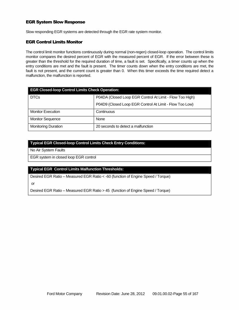
Ford Motor Company Revision Date: June 28, 2012 09.01.00.02-Page 55 of 167
EGR System Slow Response
Slow responding EGR systems are detected through the EGR rate system monitor.
EGR Control Limits Monitor
The control limit monitor functions continuously during normal (non-regen) closed-loop operation. The control limits
monitor compares the desired percent of EGR with the measured percent of EGR. If the error between these is
greater than the threshold for the required duration of time, a fault is set. Specifically, a timer counts up when the
entry conditions are met and the fault is present. The timer counts down when the entry conditions are met, the
fault is not present, and the current count is greater than 0. When this timer exceeds the time required detect a
malfunction, the malfunction is reported.
EGR Closed-loop Control Limits Check Operation:
DTCs P04DA (Closed Loop EGR Control At Limit - Flow Too High)
P04D9 (Closed Loop EGR Control At Limit - Flow Too Low)
Monitor Execution Continuous
Monitor Sequence None
Monitoring Duration 20 seconds to detect a malfunction
Typical EGR Closed-loop Control Limits Check Entry Conditions:
No Air System Faults
EGR system in closed loop EGR control
Typical EGR Control Limits Malfunction Thresholds:
Desired EGR Ratio – Measured EGR Ratio < -60 (function of Engine Speed / Torque)
or
Desired EGR Ratio – Measured EGR Ratio > 45 (function of Engine Speed / Torque)
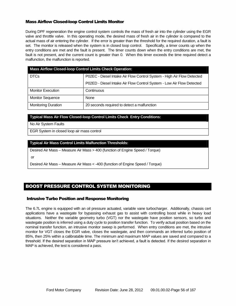
Ford Motor Company Revision Date: June 28, 2012 09.01.00.02-Page 56 of 167
Mass Airflow Closed-loop Control Limits Monitor
During DPF regeneration the engine control system controls the mass of fresh air into the cylinder using the EGR
valve and throttle valve. In this operating mode, the desired mass of fresh air in the cylinder is compared to the
actual mass of air entering the cylinder. If the error is greater than the threshold for the required duration, a fault is
set. The monitor is released when the system is in closed loop control. Specifically, a timer counts up when the
entry conditions are met and the fault is present. The timer counts down when the entry conditions are met, the
fault is not present, and the current count is greater than 0. When this timer exceeds the time required detect a
malfunction, the malfunction is reported.
Mass Airflow Closed-loop Control Limits Check Operation:
DTCs P02EC - Diesel Intake Air Flow Control System - High Air Flow Detected
P02ED - Diesel Intake Air Flow Control System - Low Air Flow Detected
Monitor Execution Continuous
Monitor Sequence None
Monitoring Duration 20 seconds required to detect a malfunction
Typical Mass Air Flow Closed-loop Control Limits Check Entry Conditions:
No Air System Faults
EGR System in closed loop air mass control
Typical Air Mass Control Limits Malfunction Thresholds:
Desired Air Mass – Measure Air Mass > 400 (function of Engine Speed / Torque)
or
Desired Air Mass – Measure Air Mass < -400 (function of Engine Speed / Torque)
BOOST PRESSURE CONTROL SYSTEM MONITORING
Intrusive Turbo Position and Response Monitoring
The 6.7L engine is equipped with an oil pressure actuated, variable vane turbocharger. Additionally, chassis cert
applications have a wastegate for bypassing exhaust gas to assist with controlling boost while in heavy load
situations. Neither the variable geometry turbo (VGT) nor the wastegate have position sensors, so turbo and
wastegate position is inferred using a duty cycle to position transfer function. To verify actual position based on the
nominal transfer function, an intrusive monitor sweep is performed. When entry conditions are met, the intrusive
monitor for VGT closes the EGR valve, closes the wastegate, and then commands an inferred turbo position of
85%, then 25% within a calibratable time. The minimum and maximum MAP values are saved and compared to a
threshold. If the desired separation in MAP pressure isn’t achieved, a fault is detected. If the desired separation in
MAP is achieved, the test is considered a pass.
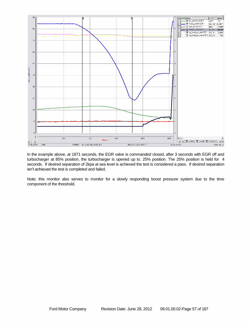
Ford Motor Company Revision Date: June 28, 2012 09.01.00.02-Page 57 of 167
In the example above, at 1871 seconds, the EGR valve is commanded closed, after 3 seconds with EGR off and
turbocharger at 85% position, the turbocharger is opened up to. 25% position. The 25% position is held for 4
seconds. If desired separation of 2kpa at sea level is achieved the test is considered a pass. If desired separation
isn’t achieved the test is completed and failed.
Note: this monitor also serves to monitor for a slowly responding boost pressure system due to the time
component of the threshold.
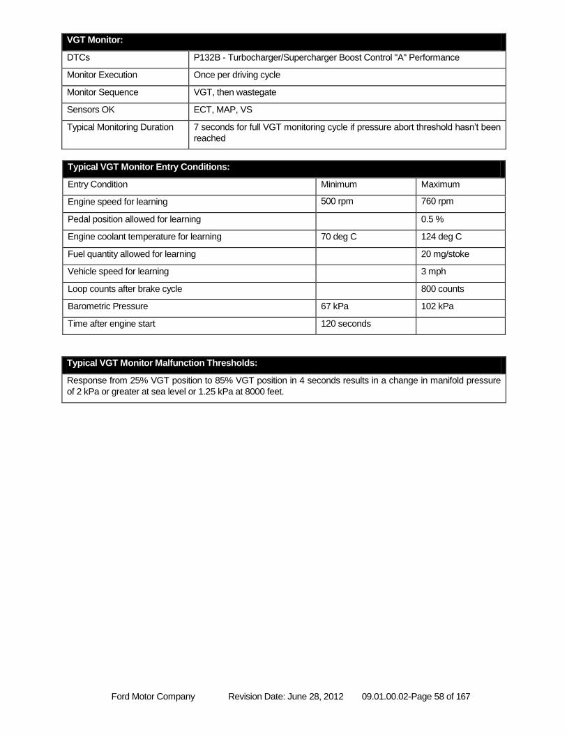
Ford Motor Company Revision Date: June 28, 2012 09.01.00.02-Page 58 of 167
VGT Monitor:
DTCs P132B - Turbocharger/Supercharger Boost Control "A" Performance
Monitor Execution Once per driving cycle
Monitor Sequence VGT, then wastegate
Sensors OK ECT, MAP, VS
Typical Monitoring Duration 7 seconds for full VGT monitoring cycle if pressure abort threshold hasn’t been
reached
Typical VGT Monitor Entry Conditions:
Entry Condition Minimum Maximum
Engine speed for learning 500 rpm 760 rpm
Pedal position allowed for learning 0.5 %
Engine coolant temperature for learning 70 deg C 124 deg C
Fuel quantity allowed for learning 20 mg/stoke
Vehicle speed for learning 3 mph
Loop counts after brake cycle 800 counts
Barometric Pressure 67 kPa 102 kPa
Time after engine start 120 seconds
Typical VGT Monitor Malfunction Thresholds:
Response from 25% VGT position to 85% VGT position in 4 seconds results in a change in manifold pressure
of 2 kPa or greater at sea level or 1.25 kPa at 8000 feet.
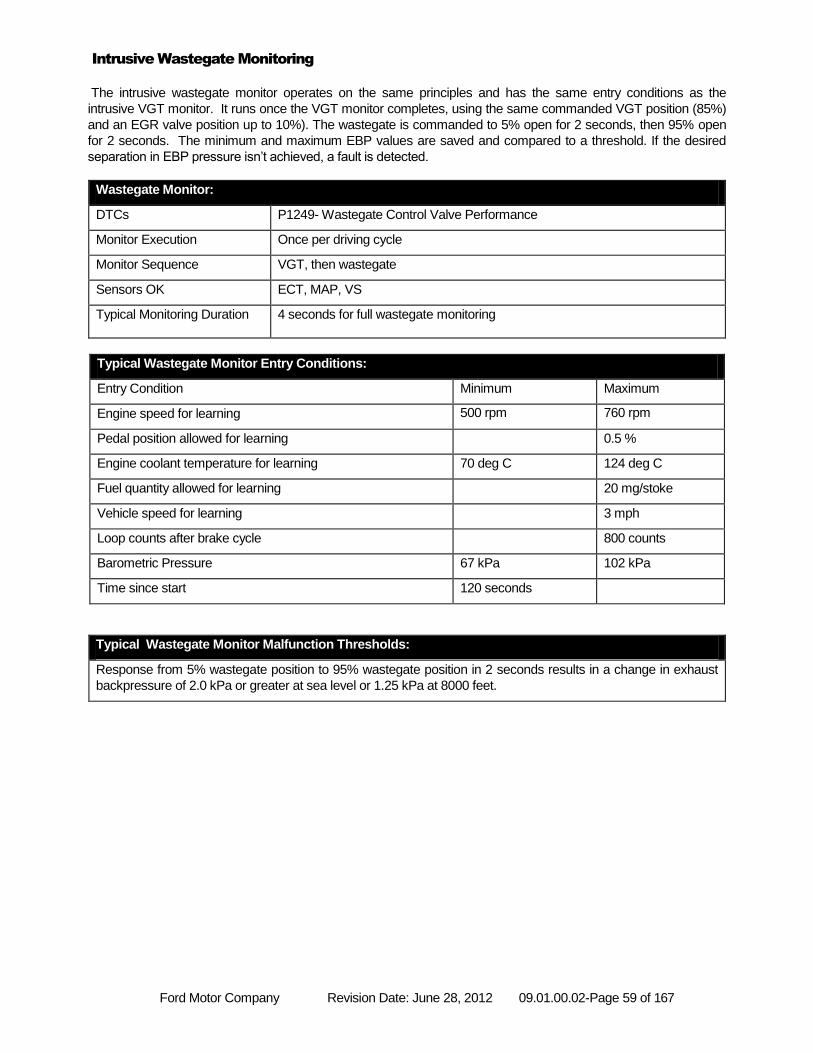
Ford Motor Company Revision Date: June 28, 2012 09.01.00.02-Page 59 of 167
Intrusive Wastegate Monitoring
The intrusive wastegate monitor operates on the same principles and has the same entry conditions as the
intrusive VGT monitor. It runs once the VGT monitor completes, using the same commanded VGT position (85%)
and an EGR valve position up to 10%). The wastegate is commanded to 5% open for 2 seconds, then 95% open
for 2 seconds. The minimum and maximum EBP values are saved and compared to a threshold. If the desired
separation in EBP pressure isn’t achieved, a fault is detected.
Wastegate Monitor:
DTCs P1249- Wastegate Control Valve Performance
Monitor Execution Once per driving cycle
Monitor Sequence VGT, then wastegate
Sensors OK ECT, MAP, VS
Typical Monitoring Duration 4 seconds for full wastegate monitoring
Typical Wastegate Monitor Entry Conditions:
Entry Condition Minimum Maximum
Engine speed for learning 500 rpm 760 rpm
Pedal position allowed for learning 0.5 %
Engine coolant temperature for learning 70 deg C 124 deg C
Fuel quantity allowed for learning 20 mg/stoke
Vehicle speed for learning 3 mph
Loop counts after brake cycle 800 counts
Barometric Pressure 67 kPa 102 kPa
Time since start 120 seconds
Typical Wastegate Monitor Malfunction Thresholds:
Response from 5% wastegate position to 95% wastegate position in 2 seconds results in a change in exhaust
backpressure of 2.0 kPa or greater at sea level or 1.25 kPa at 8000 feet.
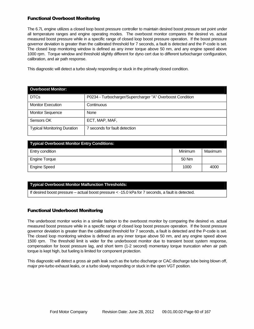
Ford Motor Company Revision Date: June 28, 2012 09.01.00.02-Page 60 of 167
Functional Overboost Monitoring
The 6.7L engine utilizes a closed loop boost pressure controller to maintain desired boost pressure set point under
all temperature ranges and engine operating modes. The overboost monitor compares the desired vs. actual
measured boost pressure while in a specific range of closed loop boost pressure operation. If the boost pressure
governor deviation is greater than the calibrated threshold for 7 seconds, a fault is detected and the P-code is set.
The closed loop monitoring window is defined as any inner torque above 50 nm, and any engine speed above
1000 rpm. Torque window and threshold slightly different for dyno cert due to different turbocharger configuration,
calibration, and air path response.
This diagnostic will detect a turbo slowly responding or stuck in the primarily closed condition.
Overboost Monitor:
DTCs P0234 - Turbocharger/Supercharger "A" Overboost Condition
Monitor Execution Continuous
Monitor Sequence None
Sensors OK ECT, MAP, MAF,
Typical Monitoring Duration 7 seconds for fault detection
Typical Overboost Monitor Entry Conditions:
Entry condition Minimum Maximum
Engine Torque 50 Nm
Engine Speed 1000 4000
Typical Overboost Monitor Malfunction Thresholds:
If desired boost pressure – actual boost pressure < -15.0 kPa for 7 seconds, a fault is detected.
Functional Underboost Monitoring
The underboost monitor works in a similar fashion to the overboost monitor by comparing the desired vs. actual
measured boost pressure while in a specific range of closed loop boost pressure operation. If the boost pressure
governor deviation is greater than the calibrated threshold for 7 seconds, a fault is detected and the P-code is set.
The closed loop monitoring window is defined as any inner torque above 50 nm, and any engine speed above
1500 rpm. The threshold limit is wider for the underbooost monitor due to transient boost system response,
compensation for boost pressure lag, and short term (1-2 second) momentary torque truncation when air path
torque is kept high, but fueling is limited for component protection.
This diagnostic will detect a gross air path leak such as the turbo discharge or CAC discharge tube being blown off,
major pre-turbo exhaust leaks, or a turbo slowly responding or stuck in the open VGT position.
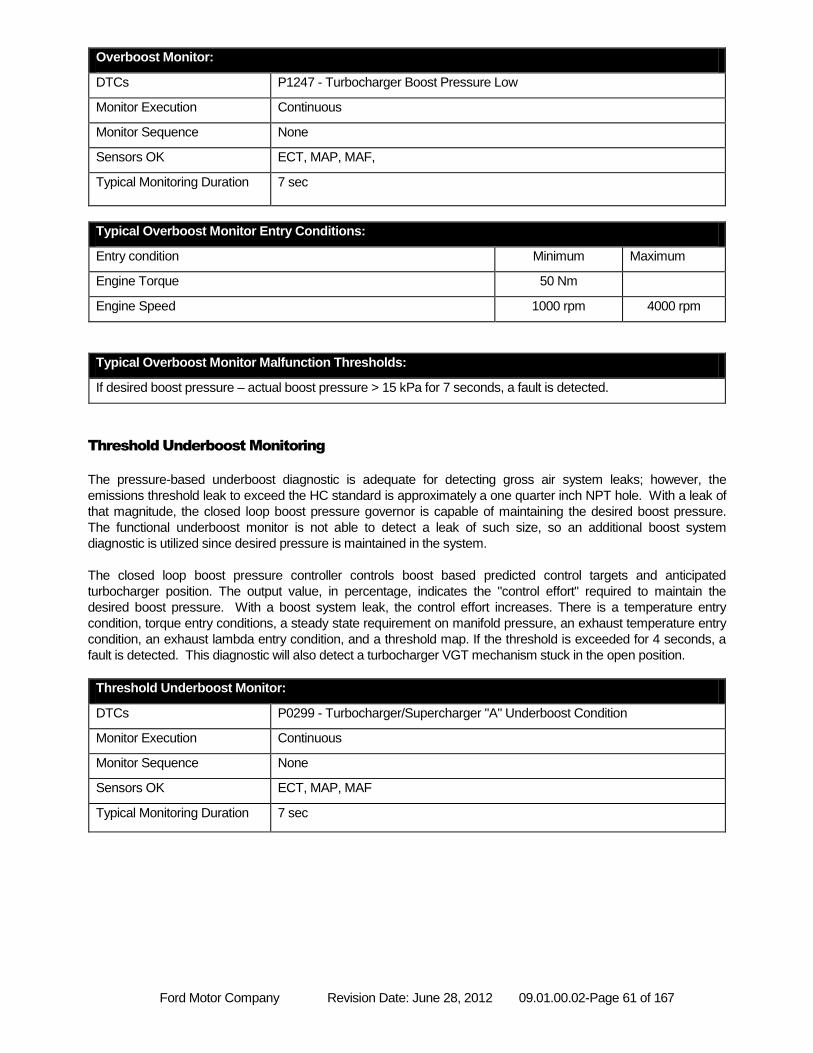
Ford Motor Company Revision Date: June 28, 2012 09.01.00.02-Page 61 of 167
Overboost Monitor:
DTCs P1247 - Turbocharger Boost Pressure Low
Monitor Execution Continuous
Monitor Sequence None
Sensors OK ECT, MAP, MAF,
Typical Monitoring Duration 7 sec
Typical Overboost Monitor Entry Conditions:
Entry condition Minimum Maximum
Engine Torque 50 Nm
Engine Speed 1000 rpm 4000 rpm
Typical Overboost Monitor Malfunction Thresholds:
If desired boost pressure – actual boost pressure > 15 kPa for 7 seconds, a fault is detected.
Threshold Underboost Monitoring
The pressure-based underboost diagnostic is adequate for detecting gross air system leaks; however, the
emissions threshold leak to exceed the HC standard is approximately a one quarter inch NPT hole. With a leak of
that magnitude, the closed loop boost pressure governor is capable of maintaining the desired boost pressure.
The functional underboost monitor is not able to detect a leak of such size, so an additional boost system
diagnostic is utilized since desired pressure is maintained in the system.
The closed loop boost pressure controller controls boost based predicted control targets and anticipated
turbocharger position. The output value, in percentage, indicates the "control effort" required to maintain the
desired boost pressure. With a boost system leak, the control effort increases. There is a temperature entry
condition, torque entry conditions, a steady state requirement on manifold pressure, an exhaust temperature entry
condition, an exhaust lambda entry condition, and a threshold map. If the threshold is exceeded for 4 seconds, a
fault is detected. This diagnostic will also detect a turbocharger VGT mechanism stuck in the open position.
Threshold Underboost Monitor:
DTCs P0299 - Turbocharger/Supercharger "A" Underboost Condition
Monitor Execution Continuous
Monitor Sequence None
Sensors OK ECT, MAP, MAF
Typical Monitoring Duration 7 sec
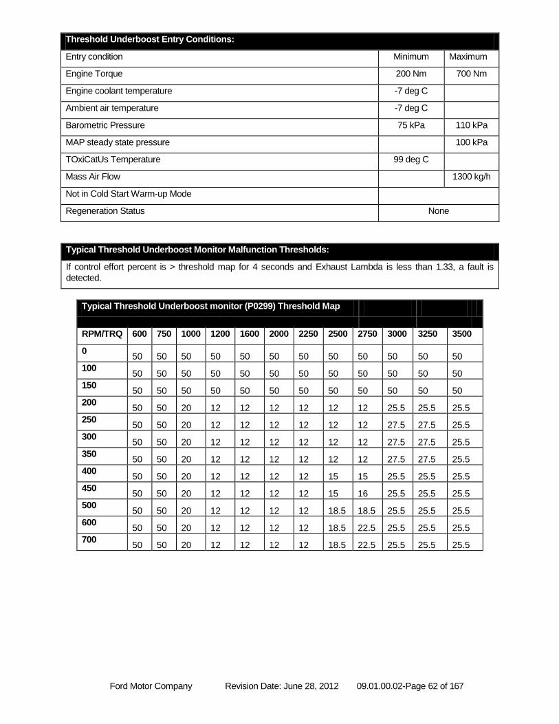
Ford Motor Company Revision Date: June 28, 2012 09.01.00.02-Page 62 of 167
Threshold Underboost Entry Conditions:
Entry condition Minimum Maximum
Engine Torque 200 Nm 700 Nm
Engine coolant temperature -7 deg C
Ambient air temperature -7 deg C
Barometric Pressure 75 kPa 110 kPa
MAP steady state pressure 100 kPa
TOxiCatUs Temperature 99 deg C
Mass Air Flow 1300 kg/h
Not in Cold Start Warm-up Mode
Regeneration Status None
Typical Threshold Underboost Monitor Malfunction Thresholds:
If control effort percent is > threshold map for 4 seconds and Exhaust Lambda is less than 1.33, a fault is
detected.
Typical Threshold Underboost monitor (P0299) Threshold Map
RPM/TRQ 600 750 1000 1200 1600 2000 2250 2500 2750 3000 3250 3500
0 50 50 50 50 50 50 50 50 50 50 50 50
100 50 50 50 50 50 50 50 50 50 50 50 50
150 50 50 50 50 50 50 50 50 50 50 50 50
200 50 50 20 12 12 12 12 12 12 25.5 25.5 25.5
250 50 50 20 12 12 12 12 12 12 27.5 27.5 25.5
300 50 50 20 12 12 12 12 12 12 27.5 27.5 25.5
350 50 50 20 12 12 12 12 12 12 27.5 27.5 25.5
400 50 50 20 12 12 12 12 15 15 25.5 25.5 25.5
450 50 50 20 12 12 12 12 15 16 25.5 25.5 25.5
500 50 50 20 12 12 12 12 18.5 18.5 25.5 25.5 25.5
600 50 50 20 12 12 12 12 18.5 22.5 25.5 25.5 25.5
700 50 50 20 12 12 12 12 18.5 22.5 25.5 25.5 25.5
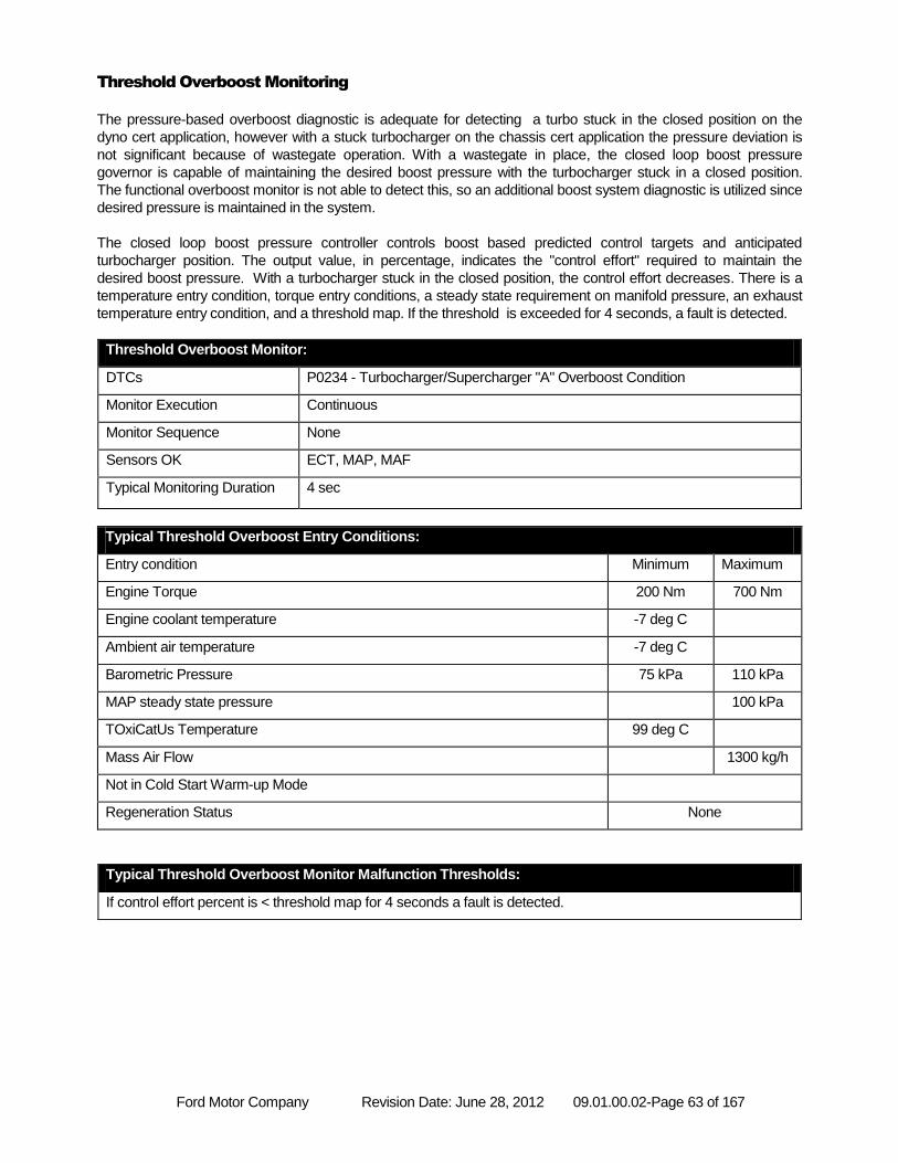
Ford Motor Company Revision Date: June 28, 2012 09.01.00.02-Page 63 of 167
Threshold Overboost Monitoring
The pressure-based overboost diagnostic is adequate for detecting a turbo stuck in the closed position on the
dyno cert application, however with a stuck turbocharger on the chassis cert application the pressure deviation is
not significant because of wastegate operation. With a wastegate in place, the closed loop boost pressure
governor is capable of maintaining the desired boost pressure with the turbocharger stuck in a closed position.
The functional overboost monitor is not able to detect this, so an additional boost system diagnostic is utilized since
desired pressure is maintained in the system.
The closed loop boost pressure controller controls boost based predicted control targets and anticipated
turbocharger position. The output value, in percentage, indicates the "control effort" required to maintain the
desired boost pressure. With a turbocharger stuck in the closed position, the control effort decreases. There is a
temperature entry condition, torque entry conditions, a steady state requirement on manifold pressure, an exhaust
temperature entry condition, and a threshold map. If the threshold is exceeded for 4 seconds, a fault is detected.
Threshold Overboost Monitor:
DTCs P0234 - Turbocharger/Supercharger "A" Overboost Condition
Monitor Execution Continuous
Monitor Sequence None
Sensors OK ECT, MAP, MAF
Typical Monitoring Duration 4 sec
Typical Threshold Overboost Entry Conditions:
Entry condition Minimum Maximum
Engine Torque 200 Nm 700 Nm
Engine coolant temperature -7 deg C
Ambient air temperature -7 deg C
Barometric Pressure 75 kPa 110 kPa
MAP steady state pressure 100 kPa
TOxiCatUs Temperature 99 deg C
Mass Air Flow 1300 kg/h
Not in Cold Start Warm-up Mode
Regeneration Status None
Typical Threshold Overboost Monitor Malfunction Thresholds:
If control effort percent is < threshold map for 4 seconds a fault is detected.
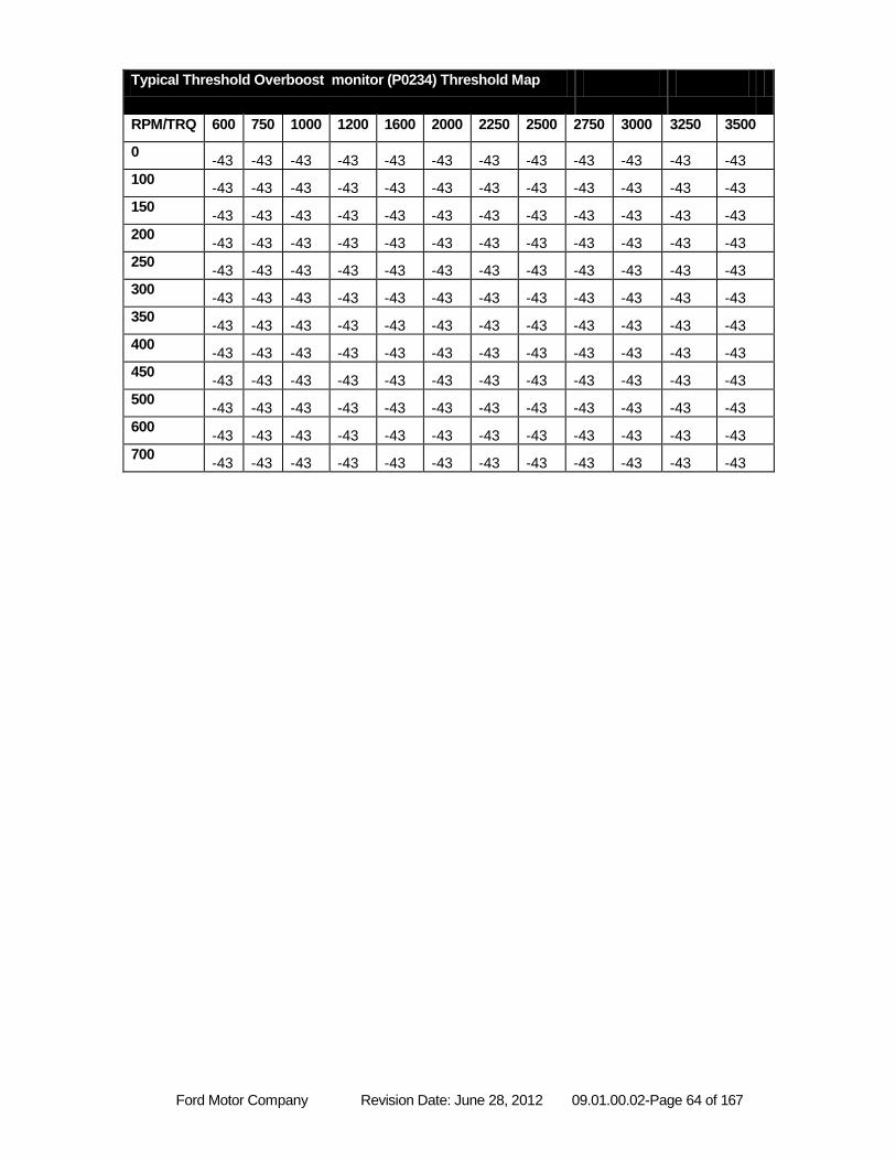
Ford Motor Company Revision Date: June 28, 2012 09.01.00.02-Page 64 of 167
Typical Threshold Overboost monitor (P0234) Threshold Map
RPM/TRQ 600 750 1000 1200 1600 2000 2250 2500 2750 3000 3250 3500
0 -43 -43 -43 -43 -43 -43 -43 -43 -43 -43 -43 -43
100 -43 -43 -43 -43 -43 -43 -43 -43 -43 -43 -43 -43
150 -43 -43 -43 -43 -43 -43 -43 -43 -43 -43 -43 -43
200 -43 -43 -43 -43 -43 -43 -43 -43 -43 -43 -43 -43
250 -43 -43 -43 -43 -43 -43 -43 -43 -43 -43 -43 -43
300 -43 -43 -43 -43 -43 -43 -43 -43 -43 -43 -43 -43
350 -43 -43 -43 -43 -43 -43 -43 -43 -43 -43 -43 -43
400 -43 -43 -43 -43 -43 -43 -43 -43 -43 -43 -43 -43
450 -43 -43 -43 -43 -43 -43 -43 -43 -43 -43 -43 -43
500 -43 -43 -43 -43 -43 -43 -43 -43 -43 -43 -43 -43
600 -43 -43 -43 -43 -43 -43 -43 -43 -43 -43 -43 -43
700 -43 -43 -43 -43 -43 -43 -43 -43 -43 -43 -43 -43
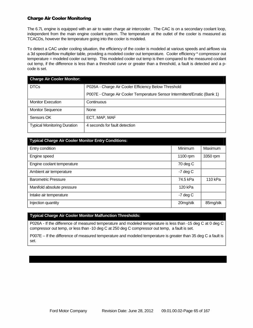
Ford Motor Company Revision Date: June 28, 2012 09.01.00.02-Page 65 of 167
Charge Air Cooler Monitoring
The 6.7L engine is equipped with an air to water charge air intercooler. The CAC is on a secondary coolant loop,
independent from the main engine coolant system. The temperature at the outlet of the cooler is measured as
TCACDs, however the temperature going into the cooler is modeled.
To detect a CAC under cooling situation, the efficiency of the cooler is modeled at various speeds and airflows via
a 3d speed/airflow multiplier table, providing a modeled cooler out temperature. Cooler efficiency * compressor out
temperature = modeled cooler out temp. This modeled cooler out temp is then compared to the measured coolant
out temp, if the difference is less than a threshold curve or greater than a threshold, a fault is detected and a p-
code is set.
Charge Air Cooler Monitor:
DTCs P026A - Charge Air Cooler Efficiency Below Threshold
P007E - Charge Air Cooler Temperature Sensor Intermittent/Erratic (Bank 1)
Monitor Execution Continuous
Monitor Sequence None
Sensors OK ECT, MAP, MAF
Typical Monitoring Duration 4 seconds for fault detection
Typical Charge Air Cooler Monitor Entry Conditions:
Entry condition Minimum Maximum
Engine speed 1100 rpm 3350 rpm
Engine coolant temperature 70 deg C
Ambient air temperature -7 deg C
Barometric Pressure 74.5 kPa 110 kPa
Manifold absolute pressure 120 kPa
Intake air temperature -7 deg C
Injection quantity 20mg/stk 85mg/stk
Typical Charge Air Cooler Monitor Malfunction Thresholds:
P026A - If the difference of measured temperature and modeled temperature is less than -15 deg C at 0 deg C
compressor out temp, or less than -10 deg C at 250 deg C compressor out temp, a fault is set.
P007E – If the difference of measured temperature and modeled temperature is greater than 35 deg C a fault is
set.
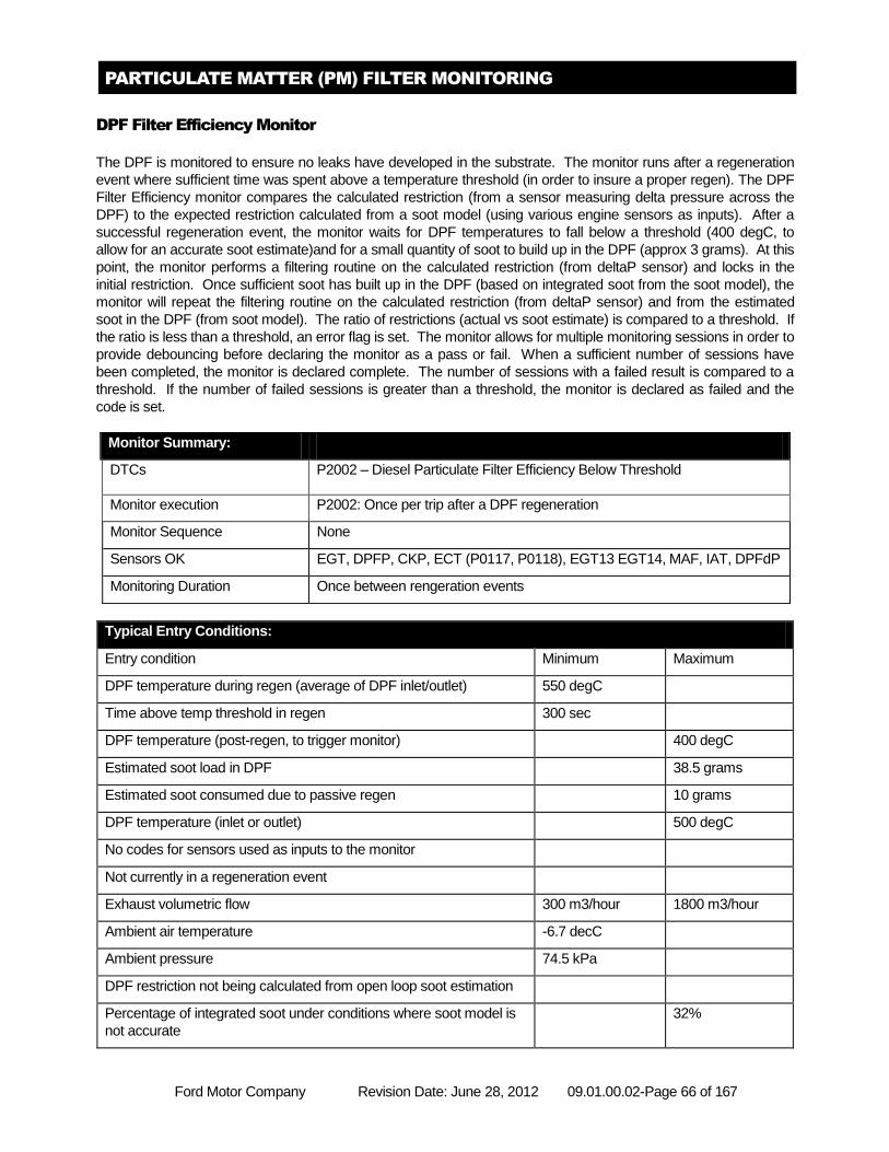
Ford Motor Company Revision Date: June 28, 2012 09.01.00.02-Page 66 of 167
PARTICULATE MATTER (PM) FILTER MONITORING
DPF Filter Efficiency Monitor
The DPF is monitored to ensure no leaks have developed in the substrate. The monitor runs after a regeneration
event where sufficient time was spent above a temperature threshold (in order to insure a proper regen). The DPF
Filter Efficiency monitor compares the calculated restriction (from a sensor measuring delta pressure across the
DPF) to the expected restriction calculated from a soot model (using various engine sensors as inputs). After a
successful regeneration event, the monitor waits for DPF temperatures to fall below a threshold (400 degC, to
allow for an accurate soot estimate)and for a small quantity of soot to build up in the DPF (approx 3 grams). At this
point, the monitor performs a filtering routine on the calculated restriction (from deltaP sensor) and locks in the
initial restriction. Once sufficient soot has built up in the DPF (based on integrated soot from the soot model), the
monitor will repeat the filtering routine on the calculated restriction (from deltaP sensor) and from the estimated
soot in the DPF (from soot model). The ratio of restrictions (actual vs soot estimate) is compared to a threshold. If
the ratio is less than a threshold, an error flag is set. The monitor allows for multiple monitoring sessions in order to
provide debouncing before declaring the monitor as a pass or fail. When a sufficient number of sessions have
been completed, the monitor is declared complete. The number of sessions with a failed result is compared to a
threshold. If the number of failed sessions is greater than a threshold, the monitor is declared as failed and the
code is set.
Monitor Summary:
DTCs P2002 – Diesel Particulate Filter Efficiency Below Threshold
Monitor execution P2002: Once per trip after a DPF regeneration
Monitor Sequence None
Sensors OK EGT, DPFP, CKP, ECT (P0117, P0118), EGT13 EGT14, MAF, IAT, DPFdP
Monitoring Duration Once between rengeration events
Typical Entry Conditions:
Entry condition Minimum Maximum
DPF temperature during regen (average of DPF inlet/outlet) 550 degC
Time above temp threshold in regen 300 sec
DPF temperature (post-regen, to trigger monitor) 400 degC
Estimated soot load in DPF 38.5 grams
Estimated soot consumed due to passive regen 10 grams
DPF temperature (inlet or outlet) 500 degC
No codes for sensors used as inputs to the monitor
Not currently in a regeneration event
Exhaust volumetric flow 300 m3/hour 1800 m3/hour
Ambient air temperature -6.7 decC
Ambient pressure 74.5 kPa
DPF restriction not being calculated from open loop soot estimation
Percentage of integrated soot under conditions where soot model is
not accurate
32%
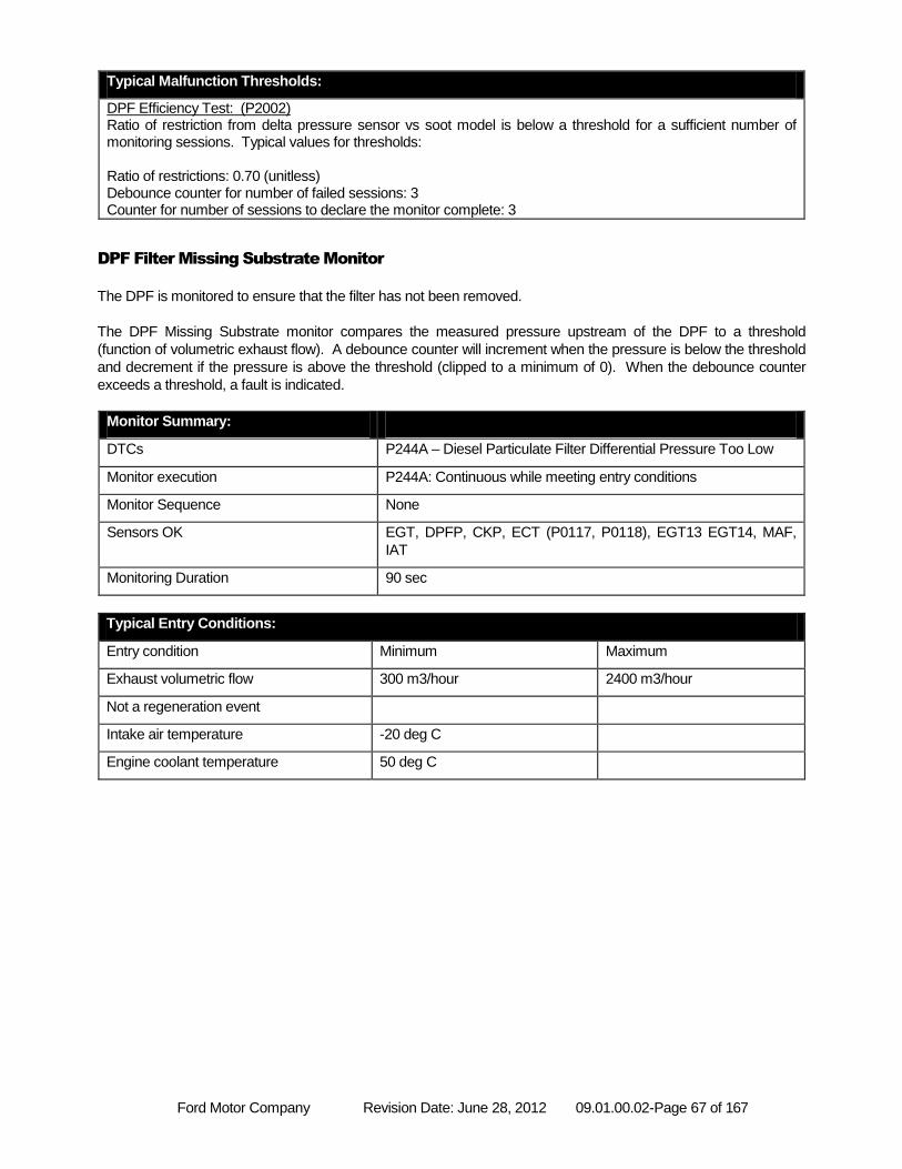
Ford Motor Company Revision Date: June 28, 2012 09.01.00.02-Page 67 of 167
Typical Malfunction Thresholds:
DPF Efficiency Test: (P2002) Ratio of restriction from delta pressure sensor vs soot model is below a threshold for a sufficient number of monitoring sessions. Typical values for thresholds: Ratio of restrictions: 0.70 (unitless) Debounce counter for number of failed sessions: 3 Counter for number of sessions to declare the monitor complete: 3
DPF Filter Missing Substrate Monitor
The DPF is monitored to ensure that the filter has not been removed.
The DPF Missing Substrate monitor compares the measured pressure upstream of the DPF to a threshold
(function of volumetric exhaust flow). A debounce counter will increment when the pressure is below the threshold
and decrement if the pressure is above the threshold (clipped to a minimum of 0). When the debounce counter
exceeds a threshold, a fault is indicated.
Monitor Summary:
DTCs P244A – Diesel Particulate Filter Differential Pressure Too Low
Monitor execution P244A: Continuous while meeting entry conditions
Monitor Sequence None
Sensors OK EGT, DPFP, CKP, ECT (P0117, P0118), EGT13 EGT14, MAF,
IAT
Monitoring Duration 90 sec
Typical Entry Conditions:
Entry condition Minimum Maximum
Exhaust volumetric flow 300 m3/hour 2400 m3/hour
Not a regeneration event
Intake air temperature -20 deg C
Engine coolant temperature 50 deg C
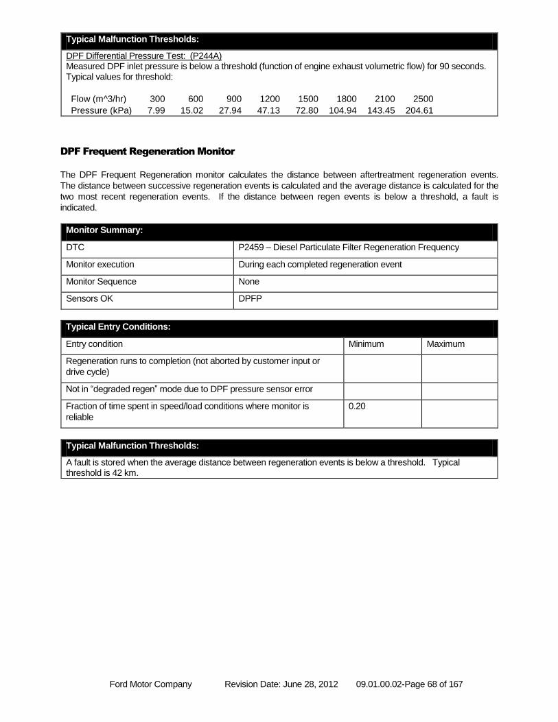
Ford Motor Company Revision Date: June 28, 2012 09.01.00.02-Page 68 of 167
Typical Malfunction Thresholds:
DPF Differential Pressure Test: (P244A) Measured DPF inlet pressure is below a threshold (function of engine exhaust volumetric flow) for 90 seconds. Typical values for threshold:
Flow (m^3/hr) 300 600 900 1200 1500 1800 2100 2500
Pressure (kPa) 7.99 15.02 27.94 47.13 72.80 104.94 143.45 204.61
DPF Frequent Regeneration Monitor
The DPF Frequent Regeneration monitor calculates the distance between aftertreatment regeneration events.
The distance between successive regeneration events is calculated and the average distance is calculated for the
two most recent regeneration events. If the distance between regen events is below a threshold, a fault is
indicated.
Monitor Summary:
DTC P2459 – Diesel Particulate Filter Regeneration Frequency
Monitor execution During each completed regeneration event
Monitor Sequence None
Sensors OK DPFP
Typical Entry Conditions:
Entry condition Minimum Maximum
Regeneration runs to completion (not aborted by customer input or
drive cycle)
Not in “degraded regen” mode due to DPF pressure sensor error
Fraction of time spent in speed/load conditions where monitor is
reliable
0.20
Typical Malfunction Thresholds:
A fault is stored when the average distance between regeneration events is below a threshold. Typical threshold is 42 km.
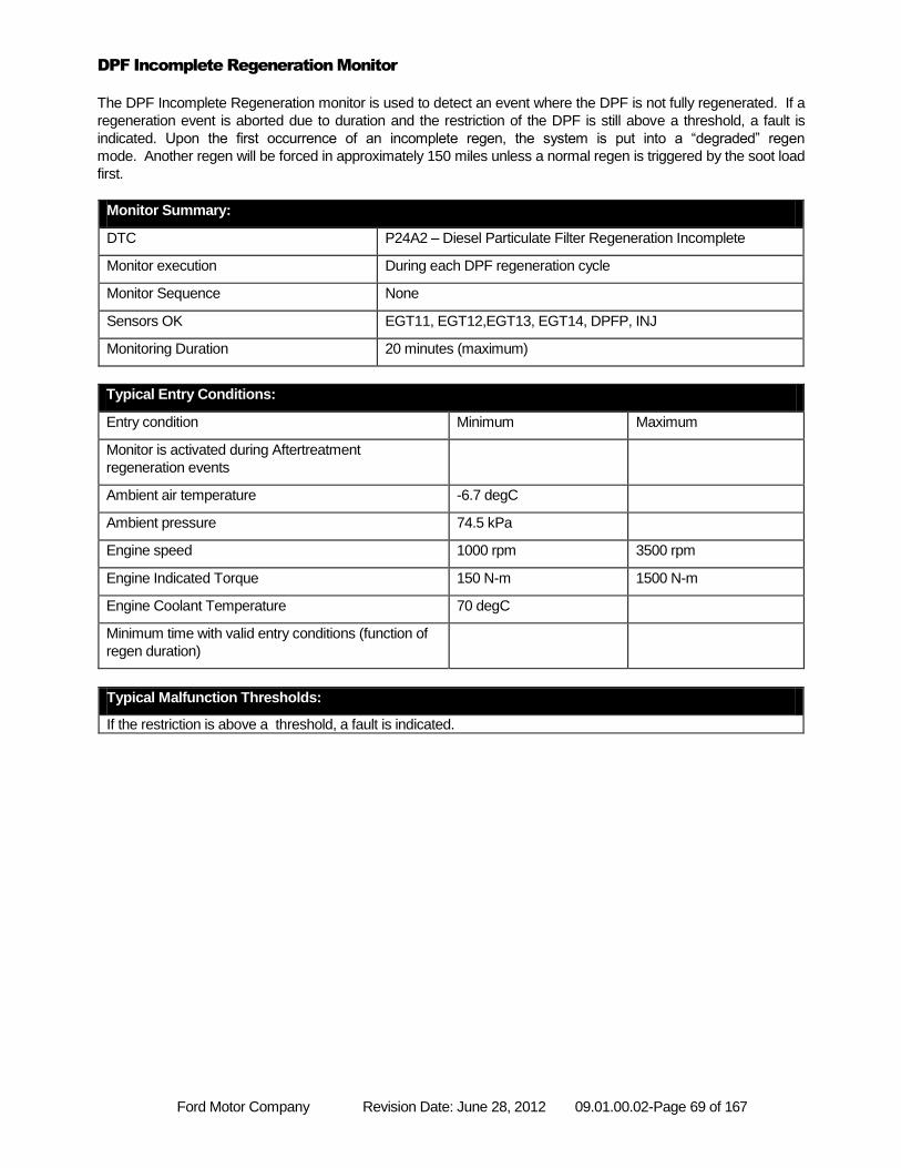
Ford Motor Company Revision Date: June 28, 2012 09.01.00.02-Page 69 of 167
DPF Incomplete Regeneration Monitor
The DPF Incomplete Regeneration monitor is used to detect an event where the DPF is not fully regenerated. If a
regeneration event is aborted due to duration and the restriction of the DPF is still above a threshold, a fault is
indicated. Upon the first occurrence of an incomplete regen, the system is put into a “degraded” regen
mode. Another regen will be forced in approximately 150 miles unless a normal regen is triggered by the soot load
first.
Monitor Summary:
DTC P24A2 – Diesel Particulate Filter Regeneration Incomplete
Monitor execution During each DPF regeneration cycle
Monitor Sequence None
Sensors OK EGT11, EGT12,EGT13, EGT14, DPFP, INJ
Monitoring Duration 20 minutes (maximum)
Typical Entry Conditions:
Entry condition Minimum Maximum
Monitor is activated during Aftertreatment
regeneration events
Ambient air temperature -6.7 degC
Ambient pressure 74.5 kPa
Engine speed 1000 rpm 3500 rpm
Engine Indicated Torque 150 N-m 1500 N-m
Engine Coolant Temperature 70 degC
Minimum time with valid entry conditions (function of
regen duration)
Typical Malfunction Thresholds:
If the restriction is above a threshold, a fault is indicated.
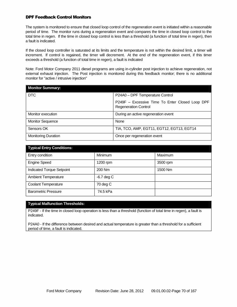
Ford Motor Company Revision Date: June 28, 2012 09.01.00.02-Page 70 of 167
DPF Feedback Control Monitors
The system is monitored to ensure that closed loop control of the regeneration event is initiated within a reasonable
period of time. The monitor runs during a regeneration event and compares the time in closed loop control to the
total time in regen. If the time in closed loop control is less than a threshold (a function of total time in regen), then
a fault is indicated.
If the closed loop controller is saturated at its limits and the temperature is not within the desired limit, a timer will
increment. If control is regained, the timer will decrement. At the end of the regeneration event, if this timer
exceeds a threshold (a function of total time in regen), a fault is indicated
Note: Ford Motor Company 2011 diesel programs are using in-cylinder post injection to achieve regeneration, not
external exhaust injection. The Post injection is monitored during this feedback monitor; there is no additional
monitor for "active / intrusive injection"
Monitor Summary:
DTC P24A0 – DPF Temperature Control
P249F – Excessive Time To Enter Closed Loop DPF
Regeneration Control
Monitor execution During an active regeneration event
Monitor Sequence None
Sensors OK TIA, TCO, AMP, EGT11, EGT12, EGT13, EGT14
Monitoring Duration Once per regeneration event
Typical Entry Conditions:
Entry condition Minimum Maximum
Engine Speed 1200 rpm 3500 rpm
Indicated Torque Setpoint 200 Nm 1500 Nm
Ambient Temperature -6.7 deg C
Coolant Temperature 70 deg C
Barometric Pressure 74.5 kPa
Typical Malfunction Thresholds:
P249F - If the time in closed loop operation is less than a threshold (function of total time in regen), a fault is indicated. P24A0 - If the difference between desired and actual temperature is greater than a threshold for a sufficient period of time, a fault is indicated.
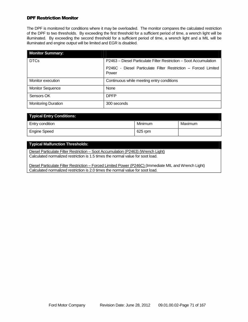
Ford Motor Company Revision Date: June 28, 2012 09.01.00.02-Page 71 of 167
DPF Restriction Monitor
The DPF is monitored for conditions where it may be overloaded. The monitor compares the calculated restriction
of the DPF to two thresholds. By exceeding the first threshold for a sufficient period of time, a wrench light will be
illuminated. By exceeding the second threshold for a sufficient period of time, a wrench light and a MIL will be
illuminated and engine output will be limited and EGR is disabled.
Monitor Summary:
DTCs P2463 – Diesel Particulate Filter Restriction – Soot Accumulation
P246C - Diesel Particulate Filter Restriction – Forced Limited
Power
Monitor execution Continuous while meeting entry conditions
Monitor Sequence None
Sensors OK DPFP
Monitoring Duration 300 seconds
Typical Entry Conditions:
Entry condition Minimum Maximum
Engine Speed 625 rpm
Typical Malfunction Thresholds:
Diesel Particulate Filter Restriction – Soot Accumulation (P2463) (Wrench Light) Calculated normalized restriction is 1.5 times the normal value for soot load. Diesel Particulate Filter Restriction – Forced Limited Power (P246C) (Immediate MIL and Wrench Light) Calculated normalized restriction is 2.0 times the normal value for soot load.
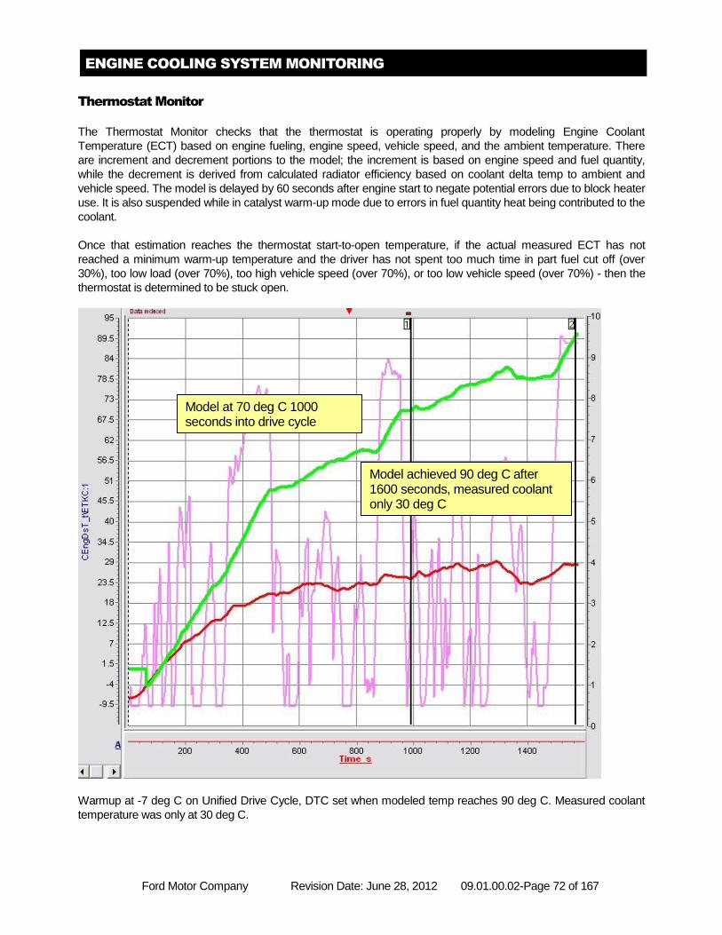
Ford Motor Company Revision Date: June 28, 2012 09.01.00.02-Page 72 of 167
ENGINE COOLING SYSTEM MONITORING
Thermostat Monitor
The Thermostat Monitor checks that the thermostat is operating properly by modeling Engine Coolant
Temperature (ECT) based on engine fueling, engine speed, vehicle speed, and the ambient temperature. There
are increment and decrement portions to the model; the increment is based on engine speed and fuel quantity,
while the decrement is derived from calculated radiator efficiency based on coolant delta temp to ambient and
vehicle speed. The model is delayed by 60 seconds after engine start to negate potential errors due to block heater
use. It is also suspended while in catalyst warm-up mode due to errors in fuel quantity heat being contributed to the
coolant.
Once that estimation reaches the thermostat start-to-open temperature, if the actual measured ECT has not
reached a minimum warm-up temperature and the driver has not spent too much time in part fuel cut off (over
30%), too low load (over 70%), too high vehicle speed (over 70%), or too low vehicle speed (over 70%) - then the
thermostat is determined to be stuck open.
Warmup at -7 deg C on Unified Drive Cycle, DTC set when modeled temp reaches 90 deg C. Measured coolant
temperature was only at 30 deg C.
Model achieved 90 deg C after 1600 seconds, measured coolant only 30 deg C
Model at 70 deg C 1000 seconds into drive cycle
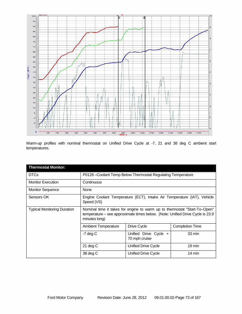
Ford Motor Company Revision Date: June 28, 2012 09.01.00.02-Page 73 of 167
Warm-up profiles with nominal thermostat on Unified Drive Cycle at -7, 21 and 38 deg C ambient start
temperatures.
Thermostat Monitor:
DTCs P0128 –Coolant Temp Below Thermostat Regulating Temperature
Monitor Execution Continuous
Monitor Sequence None
Sensors OK Engine Coolant Temperature (ECT), Intake Air Temperature (IAT), Vehicle
Speed (VS)
Typical Monitoring Duration Nominal time it takes for engine to warm up to thermostat "Start-To–Open"
temperature – see approximate times below. (Note: Unified Drive Cycle is 23.9
minutes long)
Ambient Temperature Drive Cycle Completion Time
-7 deg C Unified Drive Cycle +
70 mph cruise
33 min
21 deg C Unified Drive Cycle 19 min
38 deg C Unified Drive Cycle 14 min
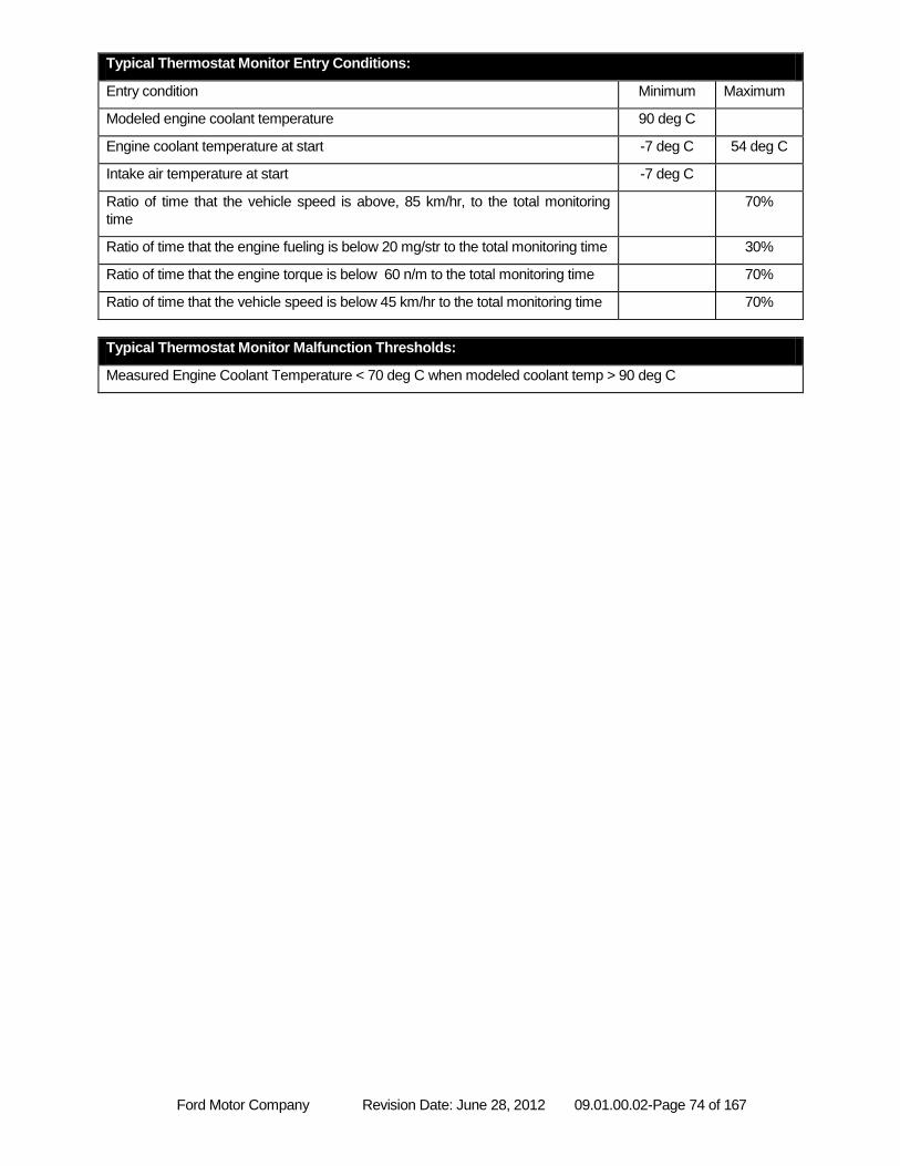
Ford Motor Company Revision Date: June 28, 2012 09.01.00.02-Page 74 of 167
Typical Thermostat Monitor Entry Conditions:
Entry condition Minimum Maximum
Modeled engine coolant temperature 90 deg C
Engine coolant temperature at start -7 deg C 54 deg C
Intake air temperature at start -7 deg C
Ratio of time that the vehicle speed is above, 85 km/hr, to the total monitoring
time
70%
Ratio of time that the engine fueling is below 20 mg/str to the total monitoring time 30%
Ratio of time that the engine torque is below 60 n/m to the total monitoring time 70%
Ratio of time that the vehicle speed is below 45 km/hr to the total monitoring time 70%
Typical Thermostat Monitor Malfunction Thresholds:
Measured Engine Coolant Temperature < 70 deg C when modeled coolant temp > 90 deg C
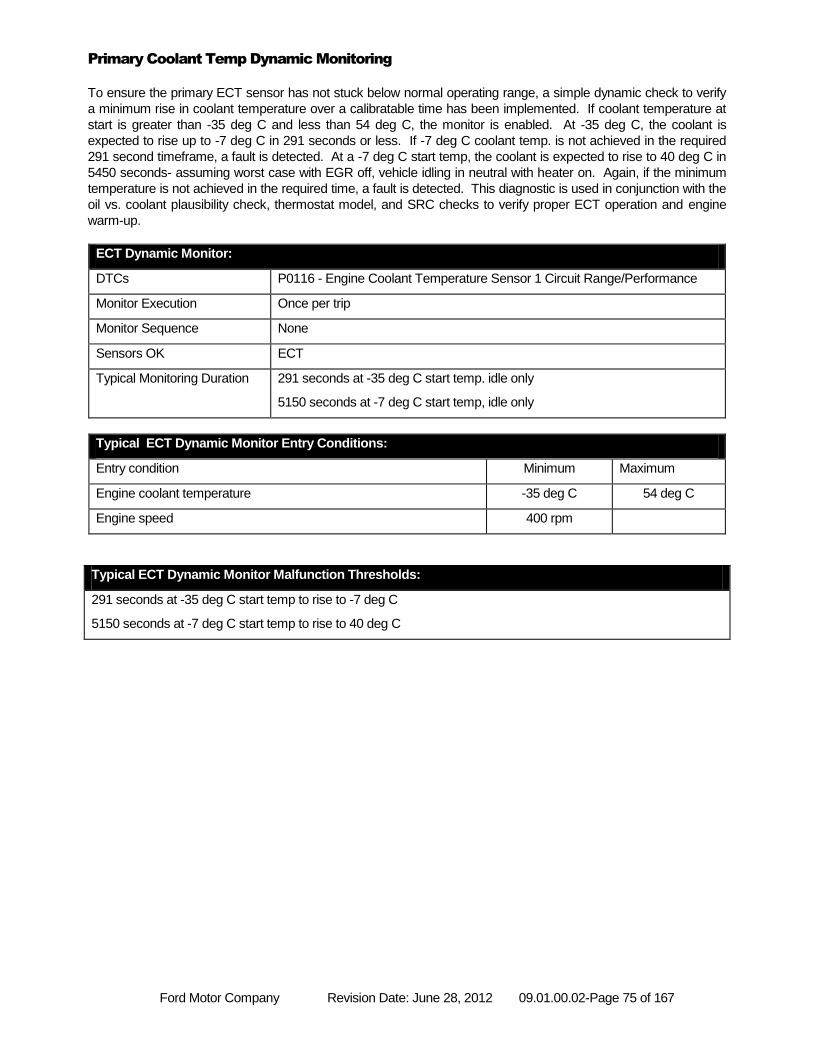
Ford Motor Company Revision Date: June 28, 2012 09.01.00.02-Page 75 of 167
Primary Coolant Temp Dynamic Monitoring
To ensure the primary ECT sensor has not stuck below normal operating range, a simple dynamic check to verify
a minimum rise in coolant temperature over a calibratable time has been implemented. If coolant temperature at
start is greater than -35 deg C and less than 54 deg C, the monitor is enabled. At -35 deg C, the coolant is
expected to rise up to -7 deg C in 291 seconds or less. If -7 deg C coolant temp. is not achieved in the required
291 second timeframe, a fault is detected. At a -7 deg C start temp, the coolant is expected to rise to 40 deg C in
5450 seconds- assuming worst case with EGR off, vehicle idling in neutral with heater on. Again, if the minimum
temperature is not achieved in the required time, a fault is detected. This diagnostic is used in conjunction with the
oil vs. coolant plausibility check, thermostat model, and SRC checks to verify proper ECT operation and engine
warm-up.
ECT Dynamic Monitor:
DTCs P0116 - Engine Coolant Temperature Sensor 1 Circuit Range/Performance
Monitor Execution Once per trip
Monitor Sequence None
Sensors OK ECT
Typical Monitoring Duration 291 seconds at -35 deg C start temp. idle only
5150 seconds at -7 deg C start temp, idle only
Typical ECT Dynamic Monitor Entry Conditions:
Entry condition Minimum Maximum
Engine coolant temperature -35 deg C 54 deg C
Engine speed 400 rpm
Typical ECT Dynamic Monitor Malfunction Thresholds:
291 seconds at -35 deg C start temp to rise to -7 deg C
5150 seconds at -7 deg C start temp to rise to 40 deg C
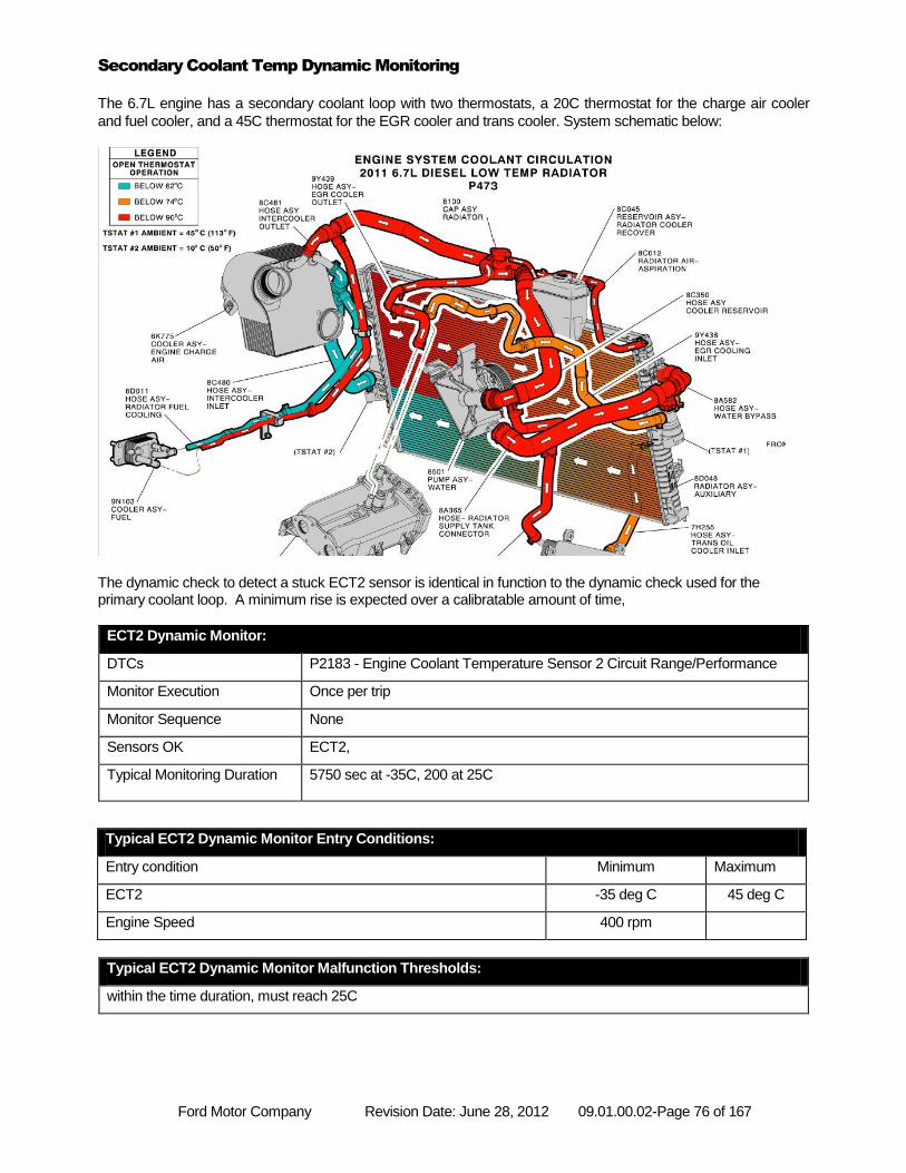
Ford Motor Company Revision Date: June 28, 2012 09.01.00.02-Page 76 of 167
Secondary Coolant Temp Dynamic Monitoring
The 6.7L engine has a secondary coolant loop with two thermostats, a 20C thermostat for the charge air cooler
and fuel cooler, and a 45C thermostat for the EGR cooler and trans cooler. System schematic below:
The dynamic check to detect a stuck ECT2 sensor is identical in function to the dynamic check used for the primary coolant loop. A minimum rise is expected over a calibratable amount of time,
ECT2 Dynamic Monitor:
DTCs P2183 - Engine Coolant Temperature Sensor 2 Circuit Range/Performance
Monitor Execution Once per trip
Monitor Sequence None
Sensors OK ECT2,
Typical Monitoring Duration 5750 sec at -35C, 200 at 25C
Typical ECT2 Dynamic Monitor Malfunction Thresholds:
within the time duration, must reach 25C
Typical ECT2 Dynamic Monitor Entry Conditions:
Entry condition Minimum Maximum
ECT2 -35 deg C 45 deg C
Engine Speed 400 rpm
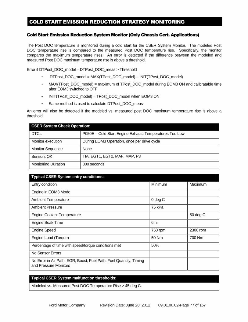
Ford Motor Company Revision Date: June 28, 2012 09.01.00.02-Page 77 of 167
COLD START EMISSION REDUCTION STRATEGY MONITORING
Cold Start Emission Reduction System Monitor (Only Chassis Cert. Applications)
The Post DOC temperature is monitored during a cold start for the CSER System Monitor. The modeled Post
DOC temperature rise is compared to the measured Post DOC temperature rise. Specifically, the monitor
compares the maximum temperature rises. An error is detected if the difference between the modeled and
measured Post DOC maximum temperature rise is above a threshold.
Error if DTPost_DOC_model – DTPost_DOC_meas > Threshold
• DTPost_DOC_model = MAX(TPost_DOC_model) – INIT(TPost_DOC_model)
• MAX(TPost_DOC_model) = maximum of TPost_DOC_model during EOM3 ON and calibratable time
after EOM3 switched to OFF
• INIT(TPost_DOC_model) = TPost_DOC_model when EOM3 ON
• Same method is used to calculate DTPost_DOC_meas
An error will also be detected if the modeled vs. measured post DOC maximum temperature rise is above a
threshold.
CSER System Check Operation:
DTCs P050E – Cold Start Engine Exhaust Temperatures Too Low
Monitor execution During EOM3 Operation, once per drive cycle
Monitor Sequence None
Sensors OK TIA, EGT1, EGT2, MAF, MAP, P3
Monitoring Duration 300 seconds
Typical CSER System entry conditions:
Entry condition Minimum Maximum
Engine in EOM3 Mode
Ambient Temperature 0 deg C
Ambient Pressure 75 kPa
Engine Coolant Temperature 50 deg C
Engine Soak Time 6 hr
Engine Speed 750 rpm 2300 rpm
Engine Load (Torque) 50 Nm 700 Nm
Percentage of time with speed/torque conditions met 50%
No Sensor Errors
No Error in Air Path, EGR, Boost, Fuel Path, Fuel Quantity, Timing
and Pressure Monitors
Typical CSER System malfunction thresholds:
Modeled vs. Measured Post DOC Temperature Rise > 45 deg C.
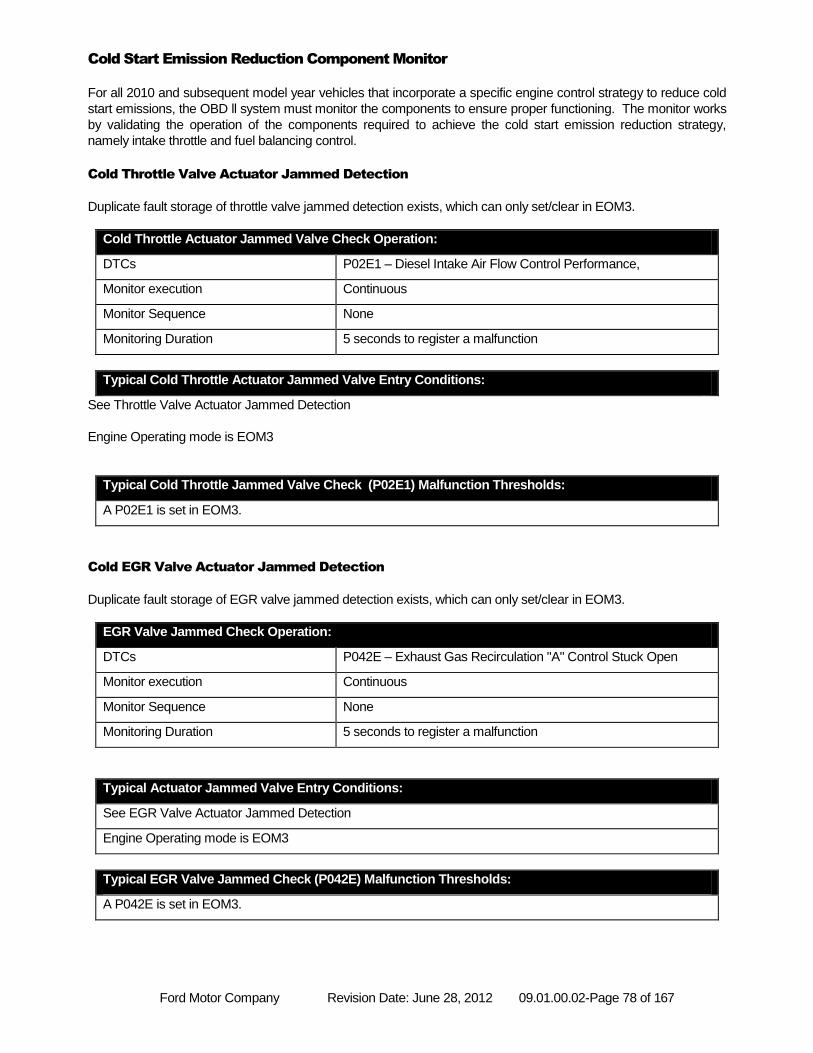
Ford Motor Company Revision Date: June 28, 2012 09.01.00.02-Page 78 of 167
Cold Start Emission Reduction Component Monitor
For all 2010 and subsequent model year vehicles that incorporate a specific engine control strategy to reduce cold
start emissions, the OBD ll system must monitor the components to ensure proper functioning. The monitor works
by validating the operation of the components required to achieve the cold start emission reduction strategy,
namely intake throttle and fuel balancing control.
Cold Throttle Valve Actuator Jammed Detection
Duplicate fault storage of throttle valve jammed detection exists, which can only set/clear in EOM3.
Cold Throttle Actuator Jammed Valve Check Operation:
DTCs P02E1 – Diesel Intake Air Flow Control Performance,
Monitor execution Continuous
Monitor Sequence None
Monitoring Duration 5 seconds to register a malfunction
Typical Cold Throttle Actuator Jammed Valve Entry Conditions:
See Throttle Valve Actuator Jammed Detection
Engine Operating mode is EOM3
Typical Cold Throttle Jammed Valve Check (P02E1) Malfunction Thresholds:
A P02E1 is set in EOM3.
Cold EGR Valve Actuator Jammed Detection
Duplicate fault storage of EGR valve jammed detection exists, which can only set/clear in EOM3.
EGR Valve Jammed Check Operation:
DTCs P042E – Exhaust Gas Recirculation "A" Control Stuck Open
Monitor execution Continuous
Monitor Sequence None
Monitoring Duration 5 seconds to register a malfunction
Typical Actuator Jammed Valve Entry Conditions:
See EGR Valve Actuator Jammed Detection
Engine Operating mode is EOM3
Typical EGR Valve Jammed Check (P042E) Malfunction Thresholds:
A P042E is set in EOM3.
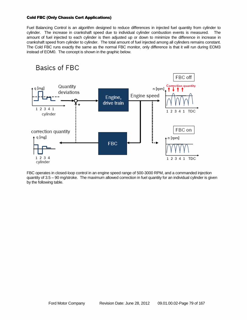
Ford Motor Company Revision Date: June 28, 2012 09.01.00.02-Page 79 of 167
Cold FBC (Only Chassis Cert Applications)
Fuel Balancing Control is an algorithm designed to reduce differences in injected fuel quantity from cylinder to
cylinder. The increase in crankshaft speed due to individual cylinder combustion events is measured. The
amount of fuel injected to each cylinder is then adjusted up or down to minimize the difference in increase in
crankshaft speed from cylinder to cylinder. The total amount of fuel injected among all cylinders remains constant.
The Cold FBC runs exactly the same as the normal FBC monitor, only difference is that it will run during EOM3
instead of EOM0. The concept is shown in the graphic below.
FBC operates in closed-loop control in an engine speed range of 500-3000 RPM, and a commanded injection quantity of 3.5 – 90 mg/stroke. The maximum allowed correction in fuel quantity for an individual cylinder is given by the following table.
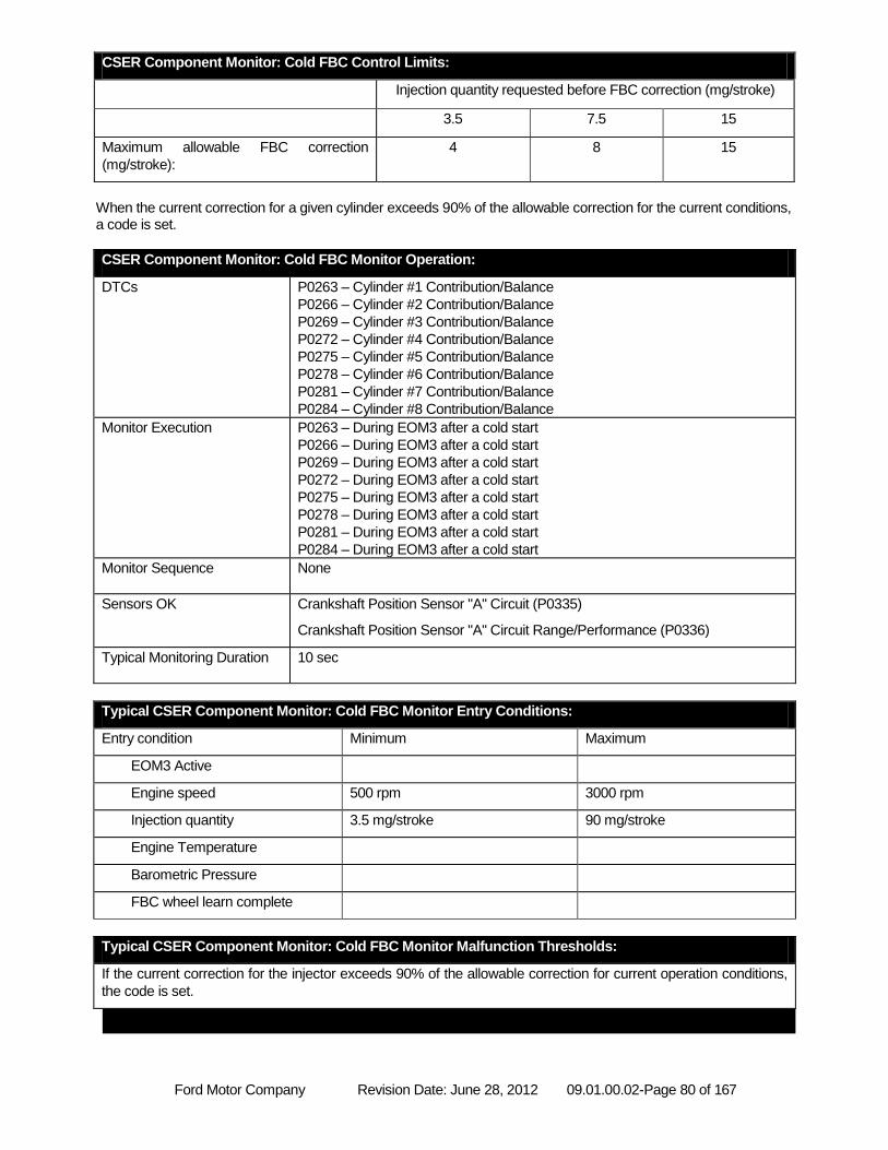
Ford Motor Company Revision Date: June 28, 2012 09.01.00.02-Page 80 of 167
CSER Component Monitor: Cold FBC Control Limits:
Injection quantity requested before FBC correction (mg/stroke)
3.5 7.5 15
Maximum allowable FBC correction
(mg/stroke):
4 8 15
When the current correction for a given cylinder exceeds 90% of the allowable correction for the current conditions, a code is set.
CSER Component Monitor: Cold FBC Monitor Operation:
DTCs P0263 – Cylinder #1 Contribution/Balance
P0266 – Cylinder #2 Contribution/Balance
P0269 – Cylinder #3 Contribution/Balance
P0272 – Cylinder #4 Contribution/Balance
P0275 – Cylinder #5 Contribution/Balance
P0278 – Cylinder #6 Contribution/Balance
P0281 – Cylinder #7 Contribution/Balance
P0284 – Cylinder #8 Contribution/Balance
Monitor Execution P0263 – During EOM3 after a cold start
P0266 – During EOM3 after a cold start
P0269 – During EOM3 after a cold start
P0272 – During EOM3 after a cold start
P0275 – During EOM3 after a cold start
P0278 – During EOM3 after a cold start
P0281 – During EOM3 after a cold start
P0284 – During EOM3 after a cold start
Monitor Sequence None
Sensors OK Crankshaft Position Sensor "A" Circuit (P0335)
Crankshaft Position Sensor "A" Circuit Range/Performance (P0336)
Typical Monitoring Duration 10 sec
Typical CSER Component Monitor: Cold FBC Monitor Entry Conditions:
Entry condition Minimum Maximum
EOM3 Active
Engine speed 500 rpm 3000 rpm
Injection quantity 3.5 mg/stroke 90 mg/stroke
Engine Temperature
Barometric Pressure
FBC wheel learn complete
Typical CSER Component Monitor: Cold FBC Monitor Malfunction Thresholds:
If the current correction for the injector exceeds 90% of the allowable correction for current operation conditions,
the code is set.
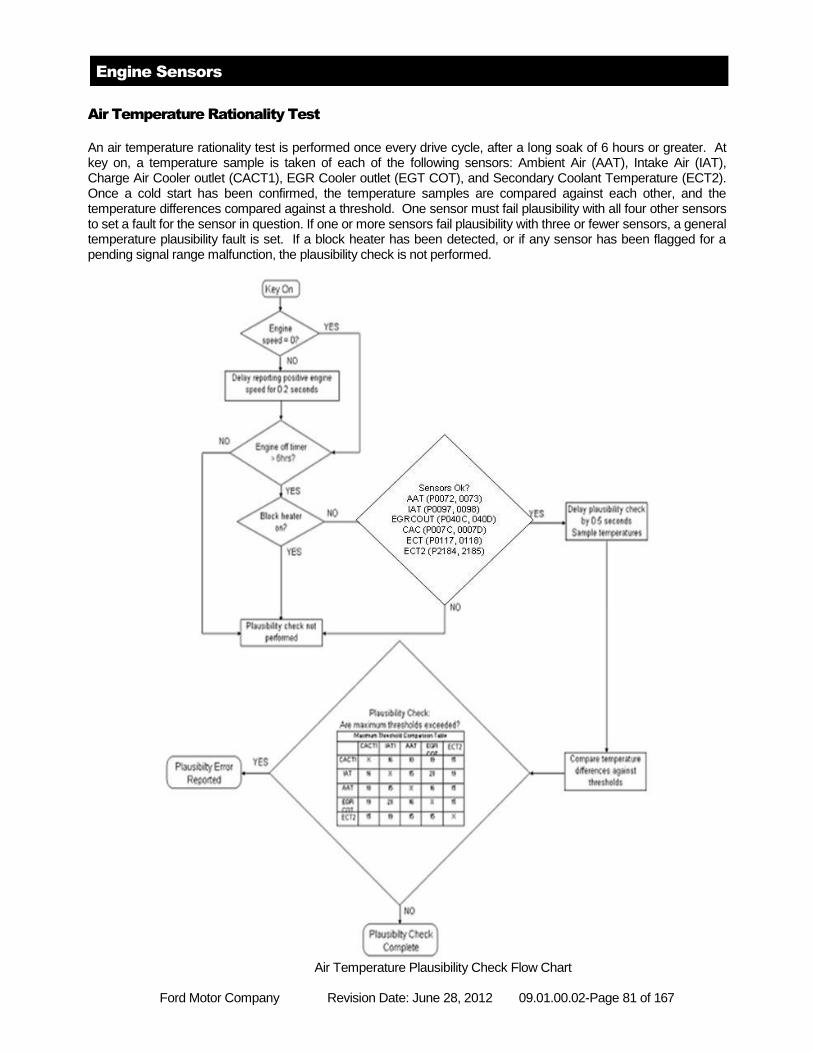
Ford Motor Company Revision Date: June 28, 2012 09.01.00.02-Page 81 of 167
Engine Sensors
Air Temperature Rationality Test
An air temperature rationality test is performed once every drive cycle, after a long soak of 6 hours or greater. At key on, a temperature sample is taken of each of the following sensors: Ambient Air (AAT), Intake Air (IAT), Charge Air Cooler outlet (CACT1), EGR Cooler outlet (EGT COT), and Secondary Coolant Temperature (ECT2). Once a cold start has been confirmed, the temperature samples are compared against each other, and the temperature differences compared against a threshold. One sensor must fail plausibility with all four other sensors to set a fault for the sensor in question. If one or more sensors fail plausibility with three or fewer sensors, a general temperature plausibility fault is set. If a block heater has been detected, or if any sensor has been flagged for a pending signal range malfunction, the plausibility check is not performed.
Air Temperature Plausibility Check Flow Chart
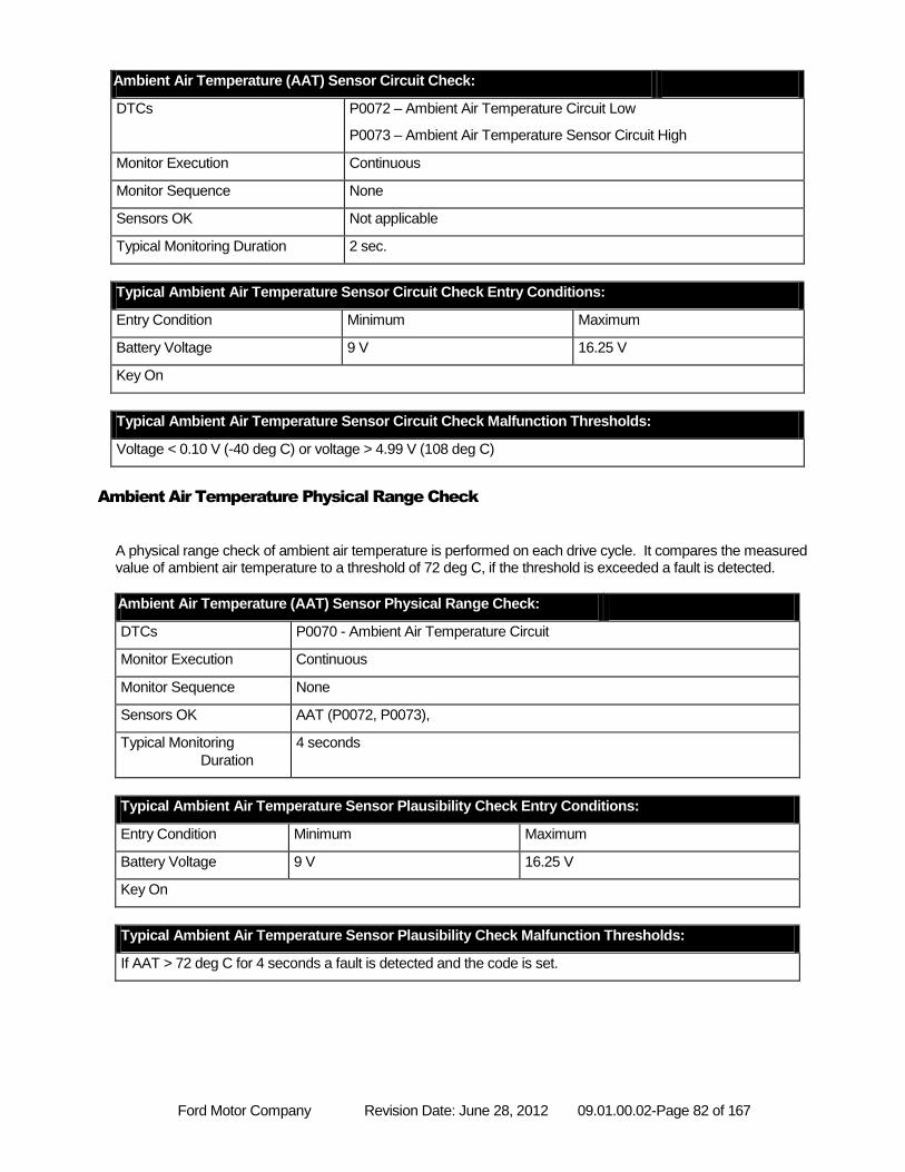
Ford Motor Company Revision Date: June 28, 2012 09.01.00.02-Page 82 of 167
Ambient Air Temperature (AAT) Sensor Circuit Check:
DTCs P0072 – Ambient Air Temperature Circuit Low
P0073 – Ambient Air Temperature Sensor Circuit High
Monitor Execution Continuous
Monitor Sequence None
Sensors OK Not applicable
Typical Monitoring Duration 2 sec.
Typical Ambient Air Temperature Sensor Circuit Check Entry Conditions:
Entry Condition Minimum Maximum
Battery Voltage 9 V 16.25 V
Key On
Typical Ambient Air Temperature Sensor Circuit Check Malfunction Thresholds:
Voltage < 0.10 V (-40 deg C) or voltage > 4.99 V (108 deg C)
Ambient Air Temperature Physical Range Check
A physical range check of ambient air temperature is performed on each drive cycle. It compares the measured value of ambient air temperature to a threshold of 72 deg C, if the threshold is exceeded a fault is detected.
Ambient Air Temperature (AAT) Sensor Physical Range Check:
DTCs P0070 - Ambient Air Temperature Circuit
Monitor Execution Continuous
Monitor Sequence None
Sensors OK AAT (P0072, P0073),
Typical Monitoring
Duration
4 seconds
Typical Ambient Air Temperature Sensor Plausibility Check Entry Conditions:
Entry Condition Minimum Maximum
Battery Voltage 9 V 16.25 V
Key On
Typical Ambient Air Temperature Sensor Plausibility Check Malfunction Thresholds:
If AAT > 72 deg C for 4 seconds a fault is detected and the code is set.
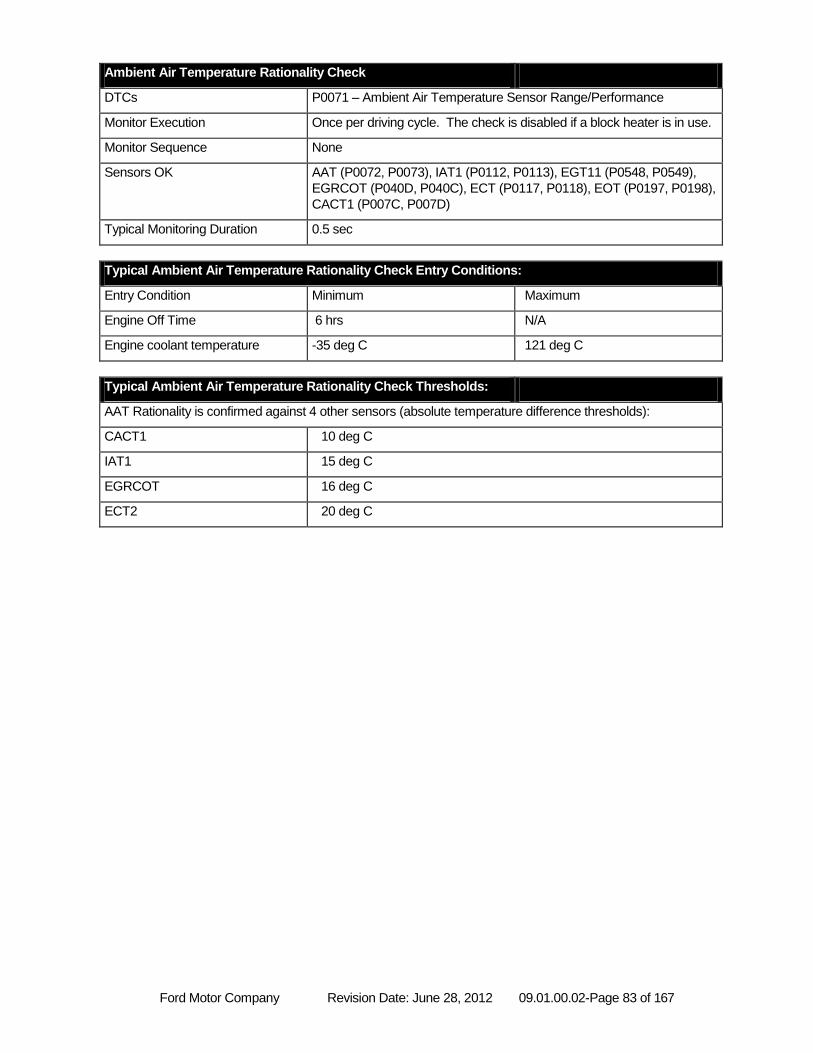
Ford Motor Company Revision Date: June 28, 2012 09.01.00.02-Page 83 of 167
Ambient Air Temperature Rationality Check
DTCs P0071 – Ambient Air Temperature Sensor Range/Performance
Monitor Execution Once per driving cycle. The check is disabled if a block heater is in use.
Monitor Sequence None
Sensors OK AAT (P0072, P0073), IAT1 (P0112, P0113), EGT11 (P0548, P0549),
EGRCOT (P040D, P040C), ECT (P0117, P0118), EOT (P0197, P0198),
CACT1 (P007C, P007D)
Typical Monitoring Duration 0.5 sec
Typical Ambient Air Temperature Rationality Check Entry Conditions:
Entry Condition Minimum Maximum
Engine Off Time 6 hrs N/A
Engine coolant temperature -35 deg C 121 deg C
Typical Ambient Air Temperature Rationality Check Thresholds:
AAT Rationality is confirmed against 4 other sensors (absolute temperature difference thresholds):
CACT1 10 deg C
IAT1 15 deg C
EGRCOT 16 deg C
ECT2 20 deg C
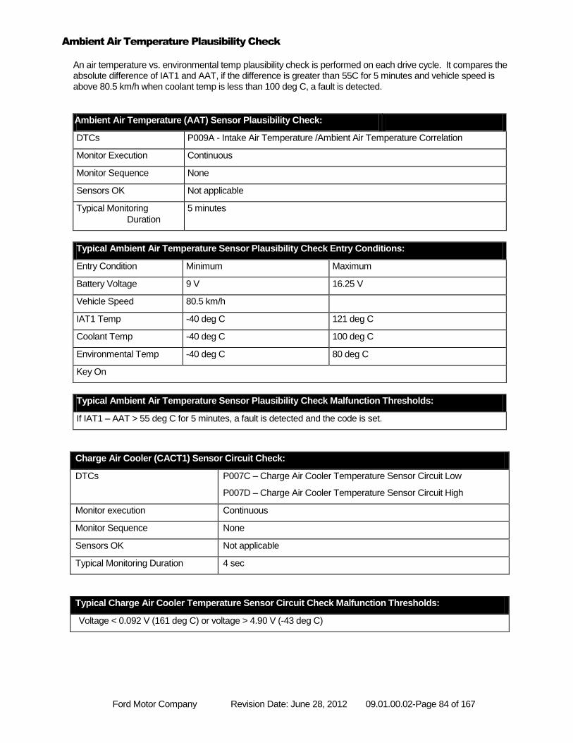
Ford Motor Company Revision Date: June 28, 2012 09.01.00.02-Page 84 of 167
Ambient Air Temperature Plausibility Check
An air temperature vs. environmental temp plausibility check is performed on each drive cycle. It compares the absolute difference of IAT1 and AAT, if the difference is greater than 55C for 5 minutes and vehicle speed is above 80.5 km/h when coolant temp is less than 100 deg C, a fault is detected.
Ambient Air Temperature (AAT) Sensor Plausibility Check:
DTCs P009A - Intake Air Temperature /Ambient Air Temperature Correlation
Monitor Execution Continuous
Monitor Sequence None
Sensors OK Not applicable
Typical Monitoring
Duration
5 minutes
Typical Ambient Air Temperature Sensor Plausibility Check Entry Conditions:
Entry Condition Minimum Maximum
Battery Voltage 9 V 16.25 V
Vehicle Speed 80.5 km/h
IAT1 Temp -40 deg C 121 deg C
Coolant Temp -40 deg C 100 deg C
Environmental Temp -40 deg C 80 deg C
Key On
Typical Ambient Air Temperature Sensor Plausibility Check Malfunction Thresholds:
If IAT1 – AAT > 55 deg C for 5 minutes, a fault is detected and the code is set.
Charge Air Cooler (CACT1) Sensor Circuit Check:
DTCs P007C – Charge Air Cooler Temperature Sensor Circuit Low
P007D – Charge Air Cooler Temperature Sensor Circuit High
Monitor execution Continuous
Monitor Sequence None
Sensors OK Not applicable
Typical Monitoring Duration 4 sec
Typical Charge Air Cooler Temperature Sensor Circuit Check Malfunction Thresholds:
Voltage < 0.092 V (161 deg C) or voltage > 4.90 V (-43 deg C)
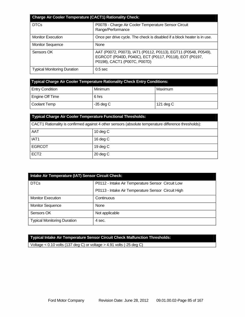
Ford Motor Company Revision Date: June 28, 2012 09.01.00.02-Page 85 of 167
Charge Air Cooler Temperature (CACT1) Rationality Check:
DTCs P007B - Charge Air Cooler Temperature Sensor Circuit
Range/Performance
Monitor Execution Once per drive cycle. The check is disabled if a block heater is in use.
Monitor Sequence None
Sensors OK AAT (P0072, P0073), IAT1 (P0112, P0113), EGT11 (P0548, P0549),
EGRCOT (P040D, P040C), ECT (P0117, P0118), EOT (P0197,
P0198), CACT1 (P007C, P007D)
Typical Monitoring Duration 0.5 sec
Typical Charge Air Cooler Temperature Rationality Check Entry Conditions:
Entry Condition Minimum Maximum
Engine Off Time 6 hrs
Coolant Temp -35 deg C 121 deg C
Typical Charge Air Cooler Temperature Functional Thresholds:
CACT1 Rationality is confirmed against 4 other sensors (absolute temperature difference thresholds):
AAT 10 deg C
IAT1 16 deg C
EGRCOT 19 deg C
ECT2 20 deg C
Intake Air Temperature (IAT) Sensor Circuit Check:
DTCs P0112 - Intake Air Temperature Sensor Circuit Low
P0113 - Intake Air Temperature Sensor Circuit High
Monitor Execution Continuous
Monitor Sequence None
Sensors OK Not applicable
Typical Monitoring Duration 4 sec.
Typical Intake Air Temperature Sensor Circuit Check Malfunction Thresholds:
Voltage < 0.10 volts (137 deg C) or voltage > 4.91 volts (-25 deg C)
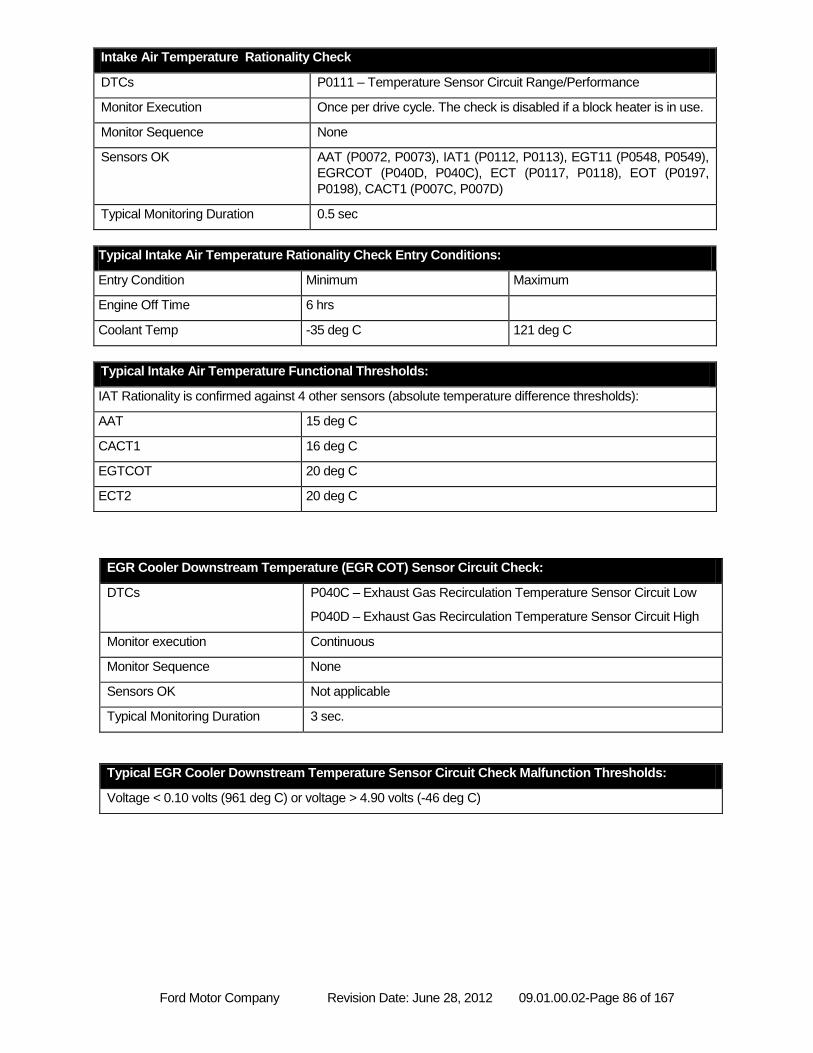
Ford Motor Company Revision Date: June 28, 2012 09.01.00.02-Page 86 of 167
Intake Air Temperature Rationality Check
DTCs P0111 – Temperature Sensor Circuit Range/Performance
Monitor Execution Once per drive cycle. The check is disabled if a block heater is in use.
Monitor Sequence None
Sensors OK AAT (P0072, P0073), IAT1 (P0112, P0113), EGT11 (P0548, P0549),
EGRCOT (P040D, P040C), ECT (P0117, P0118), EOT (P0197,
P0198), CACT1 (P007C, P007D)
Typical Monitoring Duration 0.5 sec
Typical Intake Air Temperature Rationality Check Entry Conditions:
Entry Condition Minimum Maximum
Engine Off Time 6 hrs
Coolant Temp -35 deg C 121 deg C
Typical Intake Air Temperature Functional Thresholds:
IAT Rationality is confirmed against 4 other sensors (absolute temperature difference thresholds):
AAT 15 deg C
CACT1 16 deg C
EGTCOT 20 deg C
ECT2 20 deg C
EGR Cooler Downstream Temperature (EGR COT) Sensor Circuit Check:
DTCs P040C – Exhaust Gas Recirculation Temperature Sensor Circuit Low
P040D – Exhaust Gas Recirculation Temperature Sensor Circuit High
Monitor execution Continuous
Monitor Sequence None
Sensors OK Not applicable
Typical Monitoring Duration 3 sec.
Typical EGR Cooler Downstream Temperature Sensor Circuit Check Malfunction Thresholds:
Voltage < 0.10 volts (961 deg C) or voltage > 4.90 volts (-46 deg C)
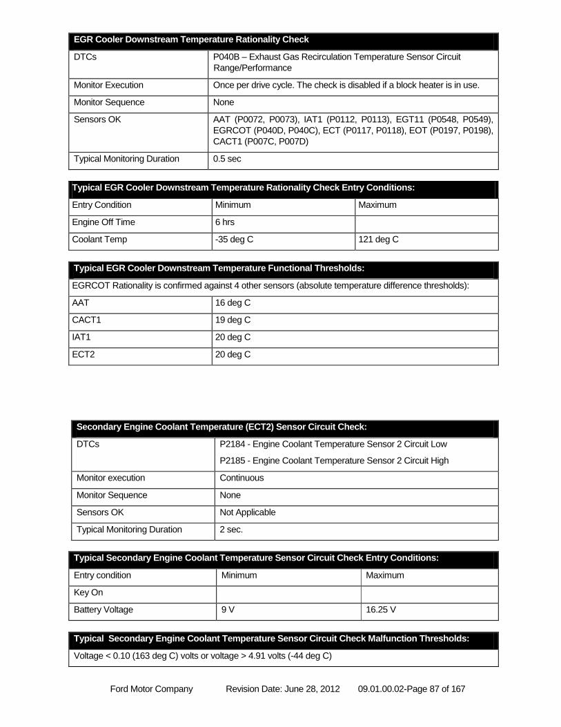
Ford Motor Company Revision Date: June 28, 2012 09.01.00.02-Page 87 of 167
EGR Cooler Downstream Temperature Rationality Check
DTCs P040B – Exhaust Gas Recirculation Temperature Sensor Circuit
Range/Performance
Monitor Execution Once per drive cycle. The check is disabled if a block heater is in use.
Monitor Sequence None
Sensors OK AAT (P0072, P0073), IAT1 (P0112, P0113), EGT11 (P0548, P0549),
EGRCOT (P040D, P040C), ECT (P0117, P0118), EOT (P0197, P0198),
CACT1 (P007C, P007D)
Typical Monitoring Duration 0.5 sec
Typical EGR Cooler Downstream Temperature Rationality Check Entry Conditions:
Entry Condition Minimum Maximum
Engine Off Time 6 hrs
Coolant Temp -35 deg C 121 deg C
Typical EGR Cooler Downstream Temperature Functional Thresholds:
EGRCOT Rationality is confirmed against 4 other sensors (absolute temperature difference thresholds):
AAT 16 deg C
CACT1 19 deg C
IAT1 20 deg C
ECT2 20 deg C
Secondary Engine Coolant Temperature (ECT2) Sensor Circuit Check:
DTCs P2184 - Engine Coolant Temperature Sensor 2 Circuit Low
P2185 - Engine Coolant Temperature Sensor 2 Circuit High
Monitor execution Continuous
Monitor Sequence None
Sensors OK Not Applicable
Typical Monitoring Duration 2 sec.
Typical Secondary Engine Coolant Temperature Sensor Circuit Check Entry Conditions:
Entry condition Minimum Maximum
Key On
Battery Voltage 9 V 16.25 V
Typical Secondary Engine Coolant Temperature Sensor Circuit Check Malfunction Thresholds:
Voltage < 0.10 (163 deg C) volts or voltage > 4.91 volts (-44 deg C)
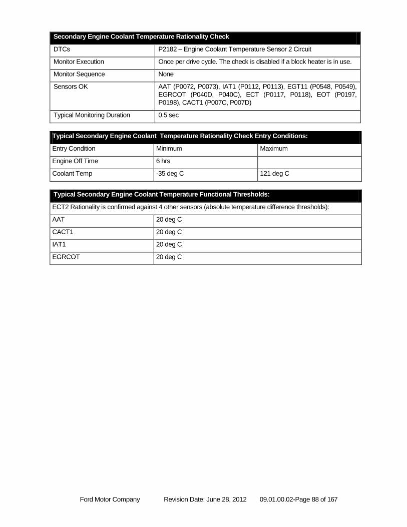
Ford Motor Company Revision Date: June 28, 2012 09.01.00.02-Page 88 of 167
Secondary Engine Coolant Temperature Rationality Check
DTCs P2182 – Engine Coolant Temperature Sensor 2 Circuit
Monitor Execution Once per drive cycle. The check is disabled if a block heater is in use.
Monitor Sequence None
Sensors OK AAT (P0072, P0073), IAT1 (P0112, P0113), EGT11 (P0548, P0549),
EGRCOT (P040D, P040C), ECT (P0117, P0118), EOT (P0197,
P0198), CACT1 (P007C, P007D)
Typical Monitoring Duration 0.5 sec
Typical Secondary Engine Coolant Temperature Rationality Check Entry Conditions:
Entry Condition Minimum Maximum
Engine Off Time 6 hrs
Coolant Temp -35 deg C 121 deg C
Typical Secondary Engine Coolant Temperature Functional Thresholds:
ECT2 Rationality is confirmed against 4 other sensors (absolute temperature difference thresholds):
AAT 20 deg C
CACT1 20 deg C
IAT1 20 deg C
EGRCOT 20 deg C
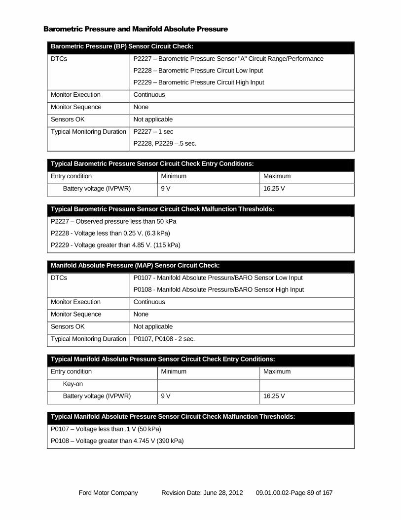
Ford Motor Company Revision Date: June 28, 2012 09.01.00.02-Page 89 of 167
Barometric Pressure and Manifold Absolute Pressure
Barometric Pressure (BP) Sensor Circuit Check:
DTCs P2227 – Barometric Pressure Sensor "A" Circuit Range/Performance
P2228 – Barometric Pressure Circuit Low Input
P2229 – Barometric Pressure Circuit High Input
Monitor Execution Continuous
Monitor Sequence None
Sensors OK Not applicable
Typical Monitoring Duration P2227 – 1 sec
P2228, P2229 –.5 sec.
Typical Barometric Pressure Sensor Circuit Check Entry Conditions:
Entry condition Minimum Maximum
Battery voltage (IVPWR) 9 V 16.25 V
Typical Barometric Pressure Sensor Circuit Check Malfunction Thresholds:
P2227 – Observed pressure less than 50 kPa
P2228 - Voltage less than 0.25 V. (6.3 kPa)
P2229 - Voltage greater than 4.85 V. (115 kPa)
Manifold Absolute Pressure (MAP) Sensor Circuit Check:
DTCs P0107 - Manifold Absolute Pressure/BARO Sensor Low Input
P0108 - Manifold Absolute Pressure/BARO Sensor High Input
Monitor Execution Continuous
Monitor Sequence None
Sensors OK Not applicable
Typical Monitoring Duration P0107, P0108 - 2 sec.
Typical Manifold Absolute Pressure Sensor Circuit Check Entry Conditions:
Entry condition Minimum Maximum
Key-on
Battery voltage (IVPWR) 9 V 16.25 V
Typical Manifold Absolute Pressure Sensor Circuit Check Malfunction Thresholds:
P0107 – Voltage less than .1 V (50 kPa)
P0108 – Voltage greater than 4.745 V (390 kPa)
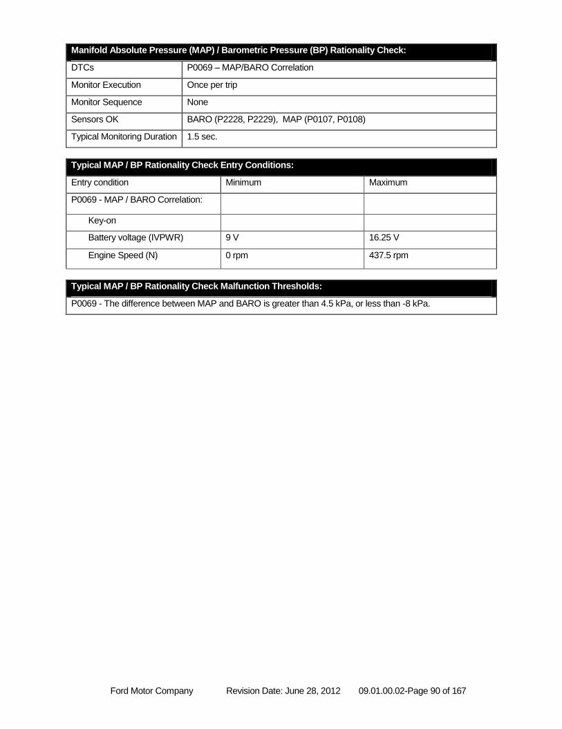
Ford Motor Company Revision Date: June 28, 2012 09.01.00.02-Page 90 of 167
Manifold Absolute Pressure (MAP) / Barometric Pressure (BP) Rationality Check:
DTCs P0069 – MAP/BARO Correlation
Monitor Execution Once per trip
Monitor Sequence None
Sensors OK BARO (P2228, P2229), MAP (P0107, P0108)
Typical Monitoring Duration 1.5 sec.
Typical MAP / BP Rationality Check Entry Conditions:
Entry condition Minimum Maximum
P0069 - MAP / BARO Correlation:
Key-on
Battery voltage (IVPWR) 9 V 16.25 V
Engine Speed (N) 0 rpm 437.5 rpm
Typical MAP / BP Rationality Check Malfunction Thresholds:
P0069 - The difference between MAP and BARO is greater than 4.5 kPa, or less than -8 kPa.
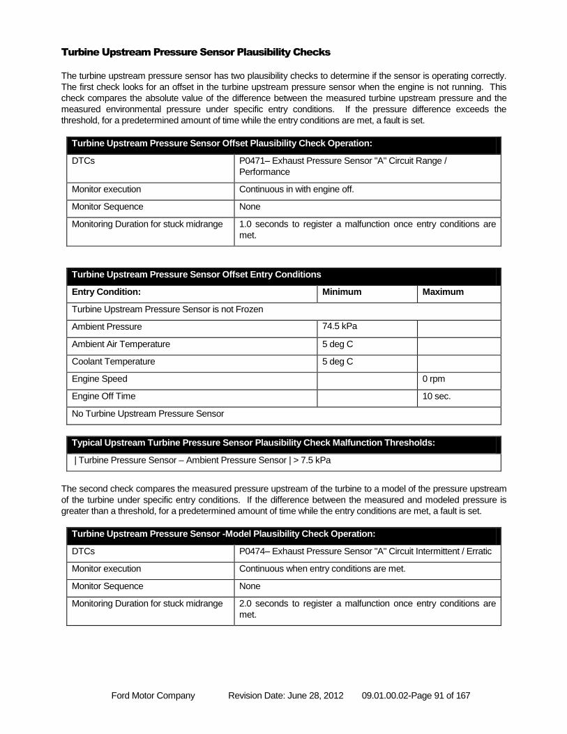
Ford Motor Company Revision Date: June 28, 2012 09.01.00.02-Page 91 of 167
Turbine Upstream Pressure Sensor Plausibility Checks
The turbine upstream pressure sensor has two plausibility checks to determine if the sensor is operating correctly.
The first check looks for an offset in the turbine upstream pressure sensor when the engine is not running. This
check compares the absolute value of the difference between the measured turbine upstream pressure and the
measured environmental pressure under specific entry conditions. If the pressure difference exceeds the
threshold, for a predetermined amount of time while the entry conditions are met, a fault is set.
Turbine Upstream Pressure Sensor Offset Plausibility Check Operation:
DTCs P0471– Exhaust Pressure Sensor "A" Circuit Range /
Performance
Monitor execution Continuous in with engine off.
Monitor Sequence None
Monitoring Duration for stuck midrange 1.0 seconds to register a malfunction once entry conditions are
met.
Turbine Upstream Pressure Sensor Offset Entry Conditions
Entry Condition: Minimum Maximum
Turbine Upstream Pressure Sensor is not Frozen
Ambient Pressure 74.5 kPa
Ambient Air Temperature 5 deg C
Coolant Temperature 5 deg C
Engine Speed 0 rpm
Engine Off Time 10 sec.
No Turbine Upstream Pressure Sensor
Typical Upstream Turbine Pressure Sensor Plausibility Check Malfunction Thresholds:
| Turbine Pressure Sensor – Ambient Pressure Sensor | > 7.5 kPa
The second check compares the measured pressure upstream of the turbine to a model of the pressure upstream
of the turbine under specific entry conditions. If the difference between the measured and modeled pressure is
greater than a threshold, for a predetermined amount of time while the entry conditions are met, a fault is set.
Turbine Upstream Pressure Sensor -Model Plausibility Check Operation:
DTCs P0474– Exhaust Pressure Sensor "A" Circuit Intermittent / Erratic
Monitor execution Continuous when entry conditions are met.
Monitor Sequence None
Monitoring Duration for stuck midrange 2.0 seconds to register a malfunction once entry conditions are
met.
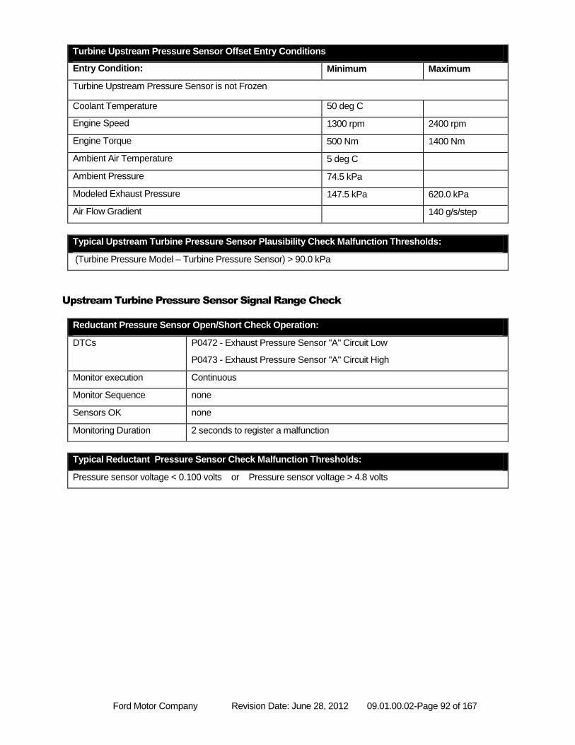
Ford Motor Company Revision Date: June 28, 2012 09.01.00.02-Page 92 of 167
Turbine Upstream Pressure Sensor Offset Entry Conditions
Entry Condition: Minimum Maximum
Turbine Upstream Pressure Sensor is not Frozen
Coolant Temperature 50 deg C
Engine Speed 1300 rpm 2400 rpm
Engine Torque 500 Nm 1400 Nm
Ambient Air Temperature 5 deg C
Ambient Pressure 74.5 kPa
Modeled Exhaust Pressure 147.5 kPa 620.0 kPa
Air Flow Gradient 140 g/s/step
Typical Upstream Turbine Pressure Sensor Plausibility Check Malfunction Thresholds:
(Turbine Pressure Model – Turbine Pressure Sensor) > 90.0 kPa
Upstream Turbine Pressure Sensor Signal Range Check
Reductant Pressure Sensor Open/Short Check Operation:
DTCs P0472 - Exhaust Pressure Sensor "A" Circuit Low
P0473 - Exhaust Pressure Sensor "A" Circuit High
Monitor execution Continuous
Monitor Sequence none
Sensors OK none
Monitoring Duration 2 seconds to register a malfunction
Typical Reductant Pressure Sensor Check Malfunction Thresholds:
Pressure sensor voltage < 0.100 volts or Pressure sensor voltage > 4.8 volts
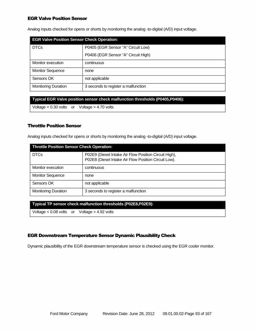
Ford Motor Company Revision Date: June 28, 2012 09.01.00.02-Page 93 of 167
EGR Valve Position Sensor
Analog inputs checked for opens or shorts by monitoring the analog -to-digital (A/D) input voltage.
EGR Valve Position Sensor Check Operation:
DTCs P0405 (EGR Sensor "A" Circuit Low)
P0406 (EGR Sensor "A" Circuit High)
Monitor execution continuous
Monitor Sequence none
Sensors OK not applicable
Monitoring Duration 3 seconds to register a malfunction
Typical EGR Valve position sensor check malfunction thresholds (P0405,P0406):
Voltage < 0.30 volts or Voltage > 4.70 volts
Throttle Position Sensor
Analog inputs checked for opens or shorts by monitoring the analog -to-digital (A/D) input voltage.
Throttle Position Sensor Check Operation:
DTCs P02E9 (Diesel Intake Air Flow Position Circuit High),
P02E8 (Diesel Intake Air Flow Position Circuit Low).
Monitor execution continuous
Monitor Sequence none
Sensors OK not applicable
Monitoring Duration 3 seconds to register a malfunction
Typical TP sensor check malfunction thresholds (P02E8,P02E9):
Voltage < 0.08 volts or Voltage > 4.92 volts
EGR Downstream Temperature Sensor Dynamic Plausibility Check
Dynamic plausibility of the EGR downstream temperature sensor is checked using the EGR cooler monitor.
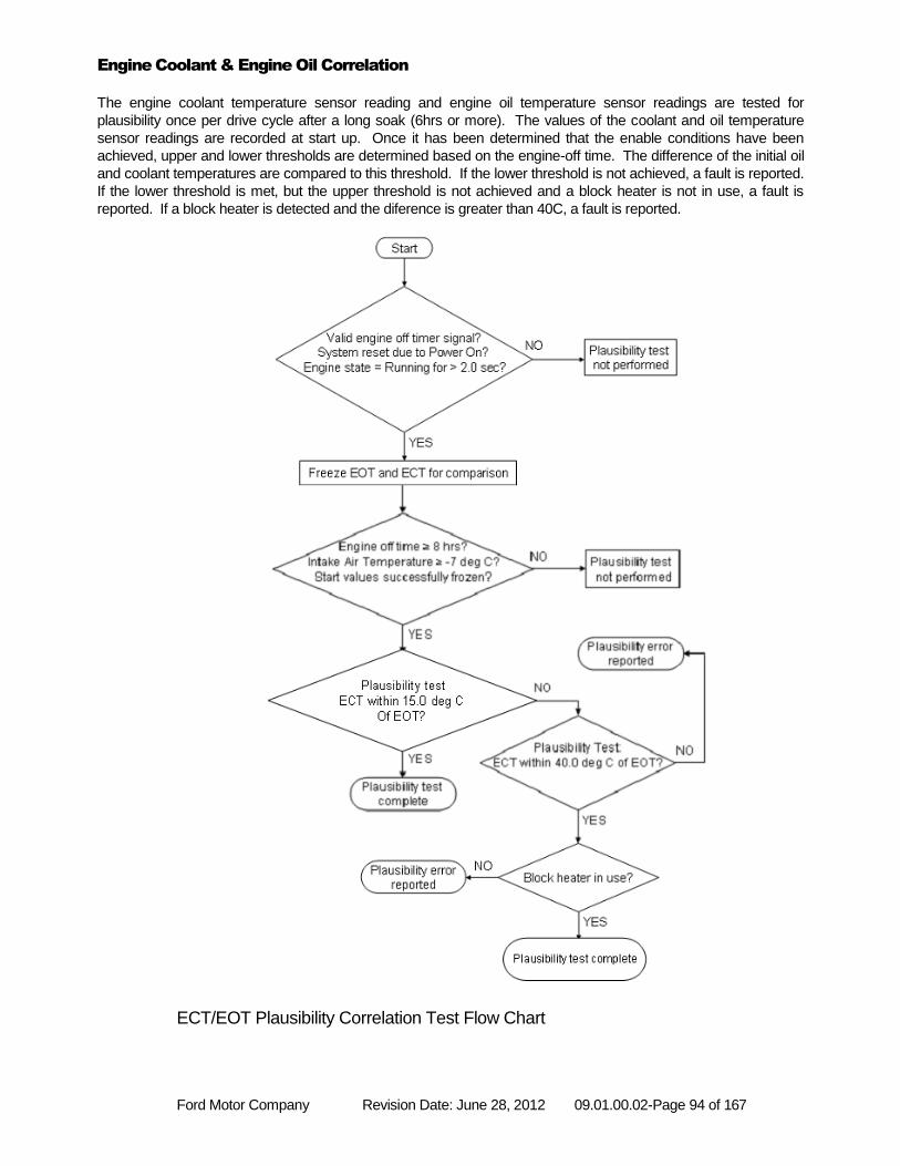
Ford Motor Company Revision Date: June 28, 2012 09.01.00.02-Page 94 of 167
Engine Coolant & Engine Oil Correlation
The engine coolant temperature sensor reading and engine oil temperature sensor readings are tested for
plausibility once per drive cycle after a long soak (6hrs or more). The values of the coolant and oil temperature
sensor readings are recorded at start up. Once it has been determined that the enable conditions have been
achieved, upper and lower thresholds are determined based on the engine-off time. The difference of the initial oil
and coolant temperatures are compared to this threshold. If the lower threshold is not achieved, a fault is reported.
If the lower threshold is met, but the upper threshold is not achieved and a block heater is not in use, a fault is
reported. If a block heater is detected and the diference is greater than 40C, a fault is reported.
ECT/EOT Plausibility Correlation Test Flow Chart
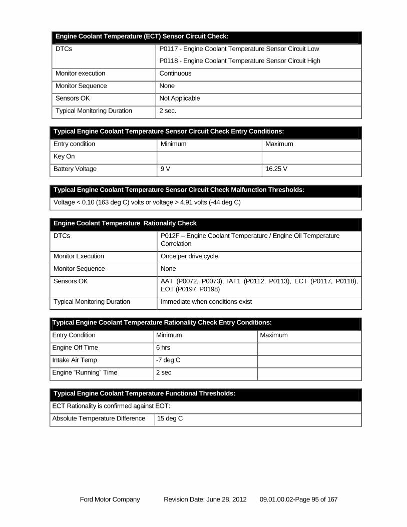
Ford Motor Company Revision Date: June 28, 2012 09.01.00.02-Page 95 of 167
Engine Coolant Temperature (ECT) Sensor Circuit Check:
DTCs P0117 - Engine Coolant Temperature Sensor Circuit Low
P0118 - Engine Coolant Temperature Sensor Circuit High
Monitor execution Continuous
Monitor Sequence None
Sensors OK Not Applicable
Typical Monitoring Duration 2 sec.
Typical Engine Coolant Temperature Sensor Circuit Check Entry Conditions:
Entry condition Minimum Maximum
Key On
Battery Voltage 9 V 16.25 V
Typical Engine Coolant Temperature Sensor Circuit Check Malfunction Thresholds:
Voltage < 0.10 (163 deg C) volts or voltage > 4.91 volts (-44 deg C)
Engine Coolant Temperature Rationality Check
DTCs P012F – Engine Coolant Temperature / Engine Oil Temperature
Correlation
Monitor Execution Once per drive cycle.
Monitor Sequence None
Sensors OK AAT (P0072, P0073), IAT1 (P0112, P0113), ECT (P0117, P0118),
EOT (P0197, P0198)
Typical Monitoring Duration Immediate when conditions exist
Typical Engine Coolant Temperature Rationality Check Entry Conditions:
Entry Condition Minimum Maximum
Engine Off Time 6 hrs
Intake Air Temp -7 deg C
Engine “Running” Time 2 sec
Typical Engine Coolant Temperature Functional Thresholds:
ECT Rationality is confirmed against EOT:
Absolute Temperature Difference 15 deg C
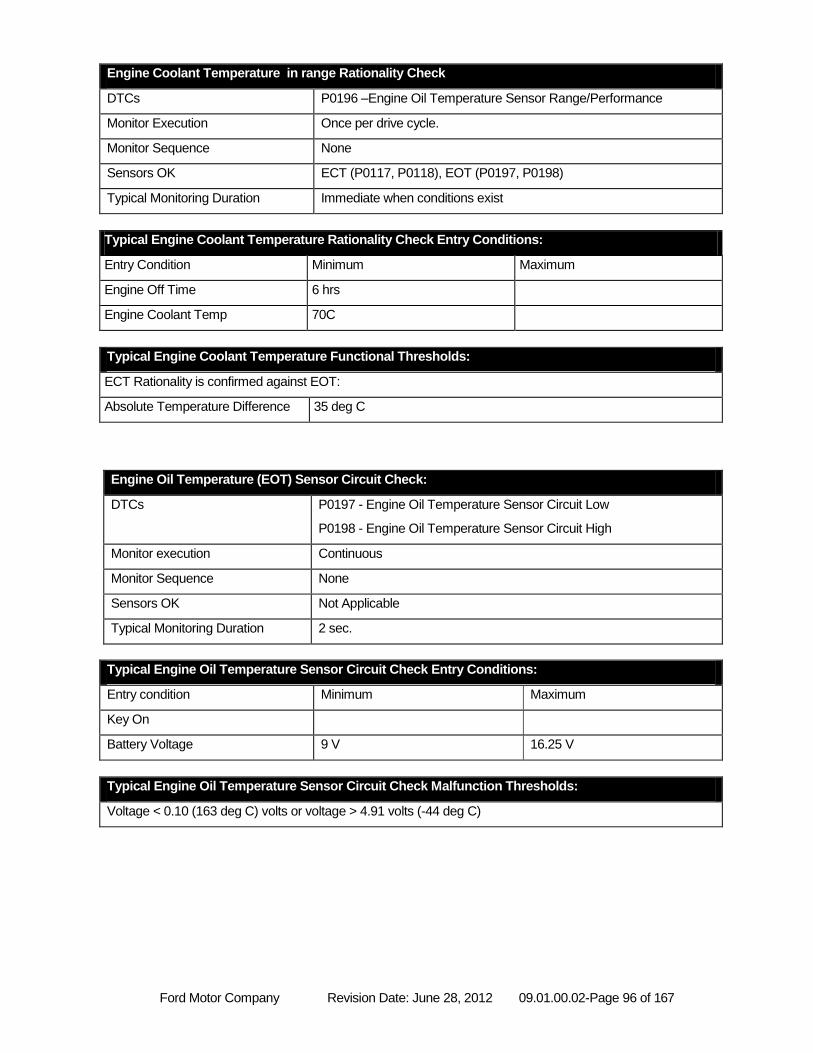
Ford Motor Company Revision Date: June 28, 2012 09.01.00.02-Page 96 of 167
Engine Coolant Temperature in range Rationality Check
DTCs P0196 –Engine Oil Temperature Sensor Range/Performance
Monitor Execution Once per drive cycle.
Monitor Sequence None
Sensors OK ECT (P0117, P0118), EOT (P0197, P0198)
Typical Monitoring Duration Immediate when conditions exist
Typical Engine Coolant Temperature Rationality Check Entry Conditions:
Entry Condition Minimum Maximum
Engine Off Time 6 hrs
Engine Coolant Temp 70C
Typical Engine Coolant Temperature Functional Thresholds:
ECT Rationality is confirmed against EOT:
Absolute Temperature Difference 35 deg C
Engine Oil Temperature (EOT) Sensor Circuit Check:
DTCs P0197 - Engine Oil Temperature Sensor Circuit Low
P0198 - Engine Oil Temperature Sensor Circuit High
Monitor execution Continuous
Monitor Sequence None
Sensors OK Not Applicable
Typical Monitoring Duration 2 sec.
Typical Engine Oil Temperature Sensor Circuit Check Entry Conditions:
Entry condition Minimum Maximum
Key On
Battery Voltage 9 V 16.25 V
Typical Engine Oil Temperature Sensor Circuit Check Malfunction Thresholds:
Voltage < 0.10 (163 deg C) volts or voltage > 4.91 volts (-44 deg C)
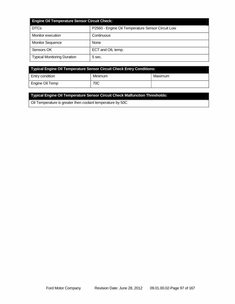
Ford Motor Company Revision Date: June 28, 2012 09.01.00.02-Page 97 of 167
Engine Oil Temperature Sensor Circuit Check:
DTCs P2560 - Engine Oil Temperature Sensor Circuit Low
Monitor execution Continuous
Monitor Sequence None
Sensors OK ECT and OIL temp.
Typical Monitoring Duration 5 sec.
Typical Engine Oil Temperature Sensor Circuit Check Entry Conditions:
Entry condition Minimum Maximum
Engine Oil Temp 70C
Typical Engine Oil Temperature Sensor Circuit Check Malfunction Thresholds:
Oil Temperature is greater then coolant temperature by 50C
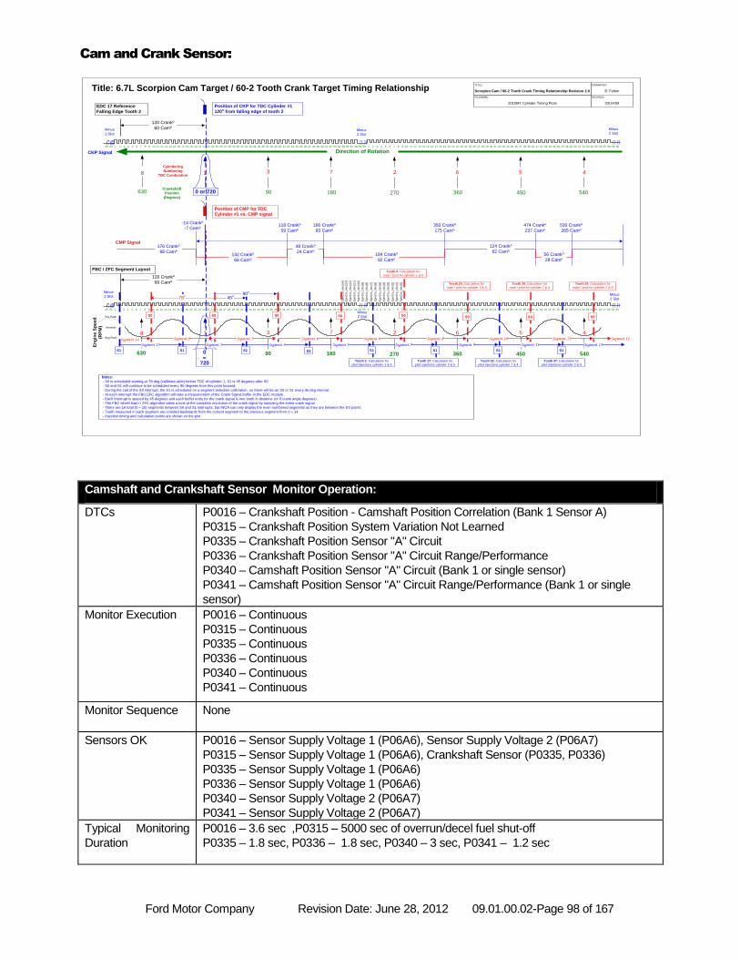
Ford Motor Company Revision Date: June 28, 2012 09.01.00.02-Page 98 of 167
Cam and Crank Sensor:
Camshaft and Crankshaft Sensor Monitor Operation:
DTCs P0016 – Crankshaft Position - Camshaft Position Correlation (Bank 1 Sensor A)
P0315 – Crankshaft Position System Variation Not Learned
P0335 – Crankshaft Position Sensor "A" Circuit
P0336 – Crankshaft Position Sensor "A" Circuit Range/Performance
P0340 – Camshaft Position Sensor "A" Circuit (Bank 1 or single sensor)
P0341 – Camshaft Position Sensor "A" Circuit Range/Performance (Bank 1 or single
sensor)
Monitor Execution P0016 – Continuous
P0315 – Continuous
P0335 – Continuous
P0336 – Continuous
P0340 – Continuous
P0341 – Continuous
Monitor Sequence None
Sensors OK P0016 – Sensor Supply Voltage 1 (P06A6), Sensor Supply Voltage 2 (P06A7)
P0315 – Sensor Supply Voltage 1 (P06A6), Crankshaft Sensor (P0335, P0336)
P0335 – Sensor Supply Voltage 1 (P06A6)
P0336 – Sensor Supply Voltage 1 (P06A6)
P0340 – Sensor Supply Voltage 2 (P06A7)
P0341 – Sensor Supply Voltage 2 (P06A7)
Typical Monitoring
Duration
P0016 – 3.6 sec ,P0315 – 5000 sec of overrun/decel fuel shut-off
P0335 – 1.8 sec, P0336 – 1.8 sec, P0340 – 3 sec, P0341 – 1.2 sec
8 673 45
180 270 360 540Crankshaft
Position
(Degrees)
2
45090
Minus
2 Slot
Minus
2 Slot
CKP Signal
Title: 6.7L Scorpion Cam Target / 60-2 Tooth Crank Target Timing Relationship
59575655535251504948474645444342414039383736353433 6032312928272625242322212019181716141097 865431 15585756555352504948474645444342414039383736353433323130292827262524232221201918171614121097 8654321 151311 60 5854301211 1351 54 59 2
Position of CKP for TDC Cylinder #1
120o from falling edge of tooth 2
630
Cylindering
Numbering
TDC Combustion
0 or 720
TITLE:
FILENAME:
2010MY Cylinder Timing Plots
DRAWN BY:
B. Fulton
REVISED:
03/14/09
Scorpion Cam / 60-2 Tooth Crank Timing Relationship Revision 2.0
120 Crankº
60 Camº
EDC 17 Reference
Falling Edge Tooth 2
Direction of Rotation
132 Crankº
66 Camº
48 Crankº
24 Camº184 Crankº
92 Camº
Position of CMP for TDC
Cylinder #1 vs. CMP signal
CMP Signal124 Crankº
62 Camº56 Crankº
28 Camº
-14 Crankº
-7 Camº118 Crankº
59 Camº
166 Crankº
83 Camº
350 Crankº
175 Camº
474 Crankº
237 Camº
530 Crankº
265 Camº
176 Crankº
88 Camº
Minus
2 Slot
6059
Tooth 2: Calculation for
pilot injections cylinder 1 & 6
Notes:
- S0 is scheduled starting at 78 deg (calibrate-able) before TDC of cylinder 1, S1 is 45 degrees after S0
- S0 and S1 will continue to be scheduled every 90 degrees from this point forward.
- During the call of the S0 interrupt, the S1 is scheduled on a segment selection calibration, so there will be an S0 or S1 every 45 deg interval.
- At each interrupt the FBC/ZFC algorithm will take a measurement of the Crank Signal buffer in the EDC module.
- Each interrupt is spaced by 45 degrees and each buffer entry for the crank signal is one tooth in distance (or 6 crank angle degrees).
- The FBC wheel learn / ZFC algorithm takes a look at the complete revolution of the crank signal by sampling the entire crank signal
- There are 16 total (0 – 15) segments between S0 and S1 interrupts, but INCA can only display the even numbered segments as they are between the S0 points
- Teeth measured in each segment are counted backwards from the current segment to the previous segment from 0 – 14
- Injection timing and calculation points are shown on the plot
Minus
2 Slot
59575655535251504948474645444342414039383736353433 6032312928272625242322212019181716141097 865431 15585756555352504948474645444342414039383736353433323130292827262524232221201918171614121097 8654321 151311 60 5854301211 1351 54 59 26059
En
gin
e S
pee
d
(RP
M) Nominal
Pos Peak
Neg Peak
8 673 45
180 270 360 540
2
45090630 0or
720
FBC / ZFC Segment Layout
Minus
2 SlotMinus
2 Slot
Tooth 9: Calculation for
main / post for cylinder 1 & 6
1
45o
1
S1
S0
S1
S0
S1
S0
S1
S0
S1
S0
S1
S0
S1
S0
S1
120 Crankº
60 Camº
Segment 0 Segment 2
Segment 1 Segment 3
Segment 4 Segment 6
Segment 5 Segment 7
Segment 8
Segment 9
Segment 10
Segment 11
Segment 12
Segment 13 Segment 14 Segment 14
Ep
mC
rs_tiIn
c[0
]
78o
Ep
mC
rs_tiIn
c[1
]
Ep
mC
rs_tiIn
c[2
]
Ep
mC
rs_tiIn
c[3
]
Ep
mC
rs_tiIn
c[4
]
Ep
mC
rs_tiIn
c[1
4]
Ep
mC
rs_tiIn
c[5
]
Ep
mC
rs_tiIn
c[6
]
Ep
mC
rs_tiIn
c[7
]
Ep
mC
rs_tiIn
c[8
]
Ep
mC
rs_tiIn
c[9
]
Ep
mC
rs_tiIn
c[1
0]
Ep
mC
rs_tiIn
c[1
1]
Ep
mC
rs_tiIn
c[1
2]
Ep
mC
rs_tiIn
c[1
3]
Segment 15
90o
S0
Tooth 17: Calculation for
pilot injections cylinder 3 & 5
Tooth 24: Calculation for
main / post for cylinder 3 & 5
Tooth 32: Calculation for
pilot injections cylinder 7 & 4
Tooth 39: Calculation for
main / post for cylinder 7 & 4
Tooth 47: Calculation for
pilot injections cylinder 2 & 8
Tooth 54: Calculation for
main / post for cylinder 2 & 8
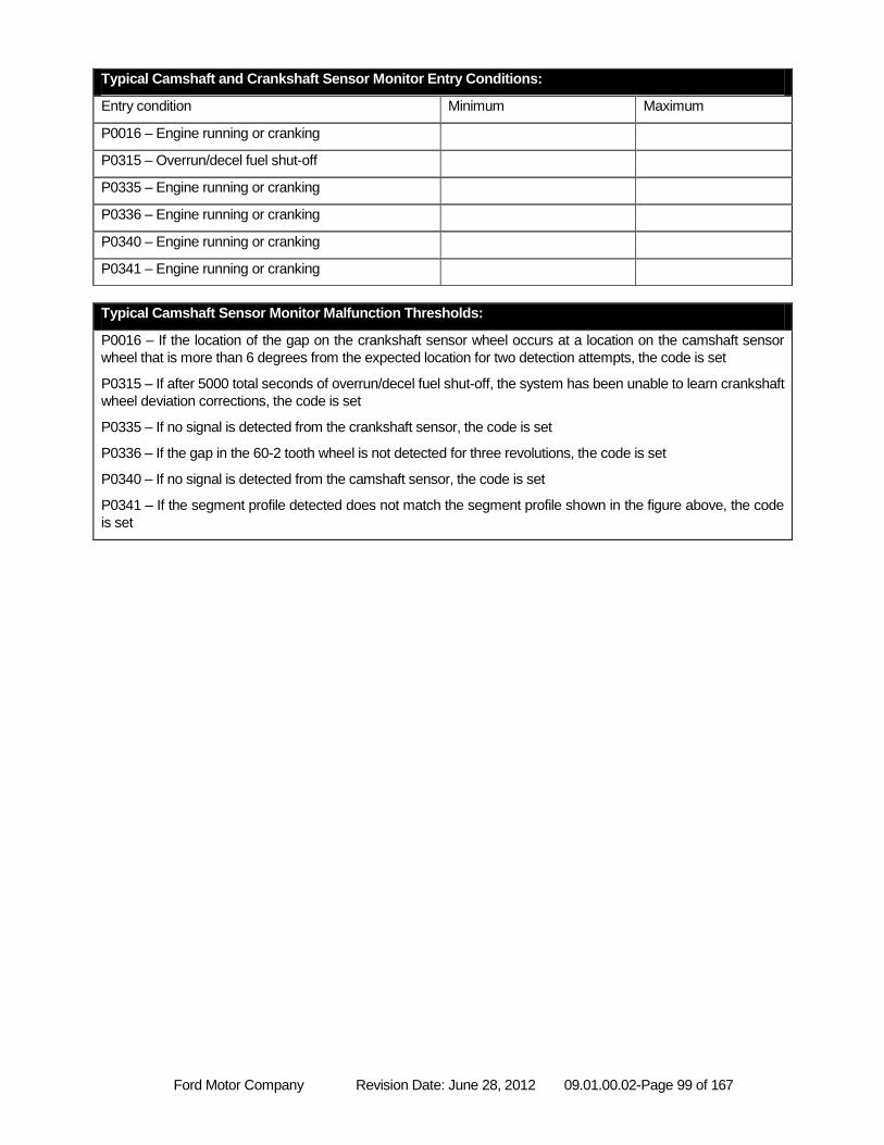
Ford Motor Company Revision Date: June 28, 2012 09.01.00.02-Page 99 of 167
Typical Camshaft and Crankshaft Sensor Monitor Entry Conditions:
Entry condition Minimum Maximum
P0016 – Engine running or cranking
P0315 – Overrun/decel fuel shut-off
P0335 – Engine running or cranking
P0336 – Engine running or cranking
P0340 – Engine running or cranking
P0341 – Engine running or cranking
Typical Camshaft Sensor Monitor Malfunction Thresholds:
P0016 – If the location of the gap on the crankshaft sensor wheel occurs at a location on the camshaft sensor
wheel that is more than 6 degrees from the expected location for two detection attempts, the code is set
P0315 – If after 5000 total seconds of overrun/decel fuel shut-off, the system has been unable to learn crankshaft
wheel deviation corrections, the code is set
P0335 – If no signal is detected from the crankshaft sensor, the code is set
P0336 – If the gap in the 60-2 tooth wheel is not detected for three revolutions, the code is set
P0340 – If no signal is detected from the camshaft sensor, the code is set
P0341 – If the segment profile detected does not match the segment profile shown in the figure above, the code
is set
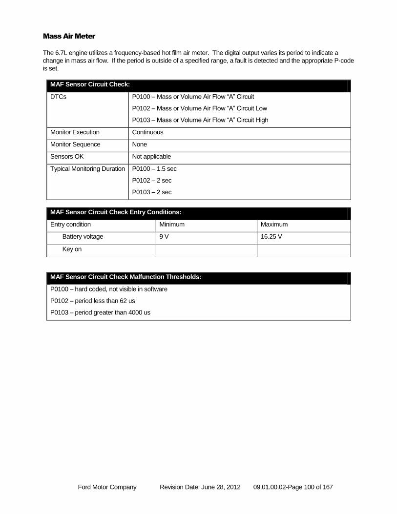
Ford Motor Company Revision Date: June 28, 2012 09.01.00.02-Page 100 of 167
Mass Air Meter
The 6.7L engine utilizes a frequency-based hot film air meter. The digital output varies its period to indicate a
change in mass air flow. If the period is outside of a specified range, a fault is detected and the appropriate P-code
is set.
MAF Sensor Circuit Check:
DTCs P0100 – Mass or Volume Air Flow “A” Circuit
P0102 – Mass or Volume Air Flow “A” Circuit Low
P0103 – Mass or Volume Air Flow “A” Circuit High
Monitor Execution Continuous
Monitor Sequence None
Sensors OK Not applicable
Typical Monitoring Duration P0100 – 1.5 sec
P0102 – 2 sec
P0103 – 2 sec
MAF Sensor Circuit Check Entry Conditions:
Entry condition Minimum Maximum
Battery voltage 9 V 16.25 V
Key on
MAF Sensor Circuit Check Malfunction Thresholds:
P0100 – hard coded, not visible in software
P0102 – period less than 62 us
P0103 – period greater than 4000 us
Ford Motor Company Revision Date: June 28, 2012 09.01.00.02-Page 101 of 167
MAF Rationality Check
A rationality check of the mass air flow sensor is performed each time an air mass adaption (AMA) executes. AMA
adapts at two points- one at idle, the other at a specific speed/load. The ratio between the mass air flow and the
reference mass air flow is calculated with the EGR valve commanded to the closed position. The release of this
plausibility check occurs under strict engine operating and environmental conditions to minimize the affect of
outside influences on mass air flow. At each AMA event, the corrected value is stored for each point. These stored
values are compared to a threshold, if the stored values are greater than a threshold a fault is detected, as the air
meter has drifted outside of its nominal operating range.
In addition to the stored values, the corrected airflow is compared to directly to the modeled airflow during AMA. If
the ratio of the corrected airflow and the modeled airflow is less than the threshold, a fault is detected.
The following figure outlines the strategy for the rationality checks.
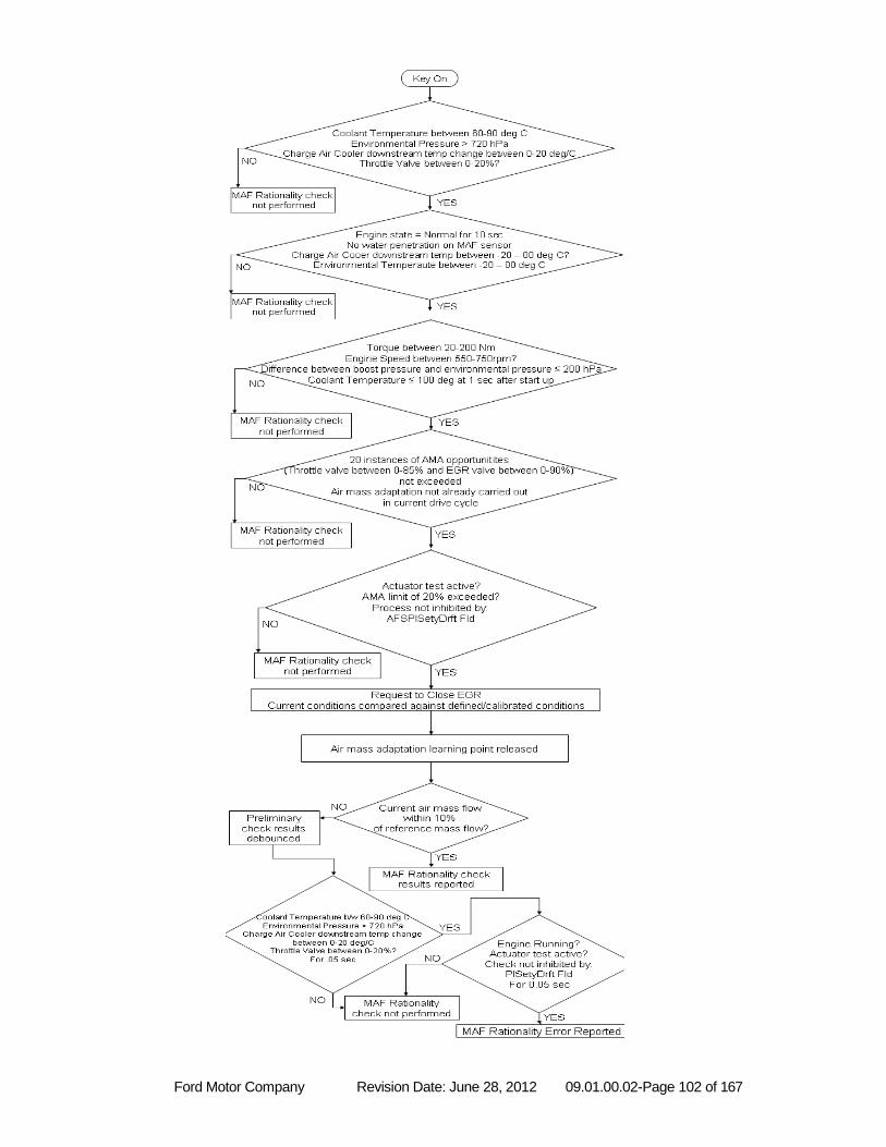
Ford Motor Company Revision Date: June 28, 2012 09.01.00.02-Page 102 of 167
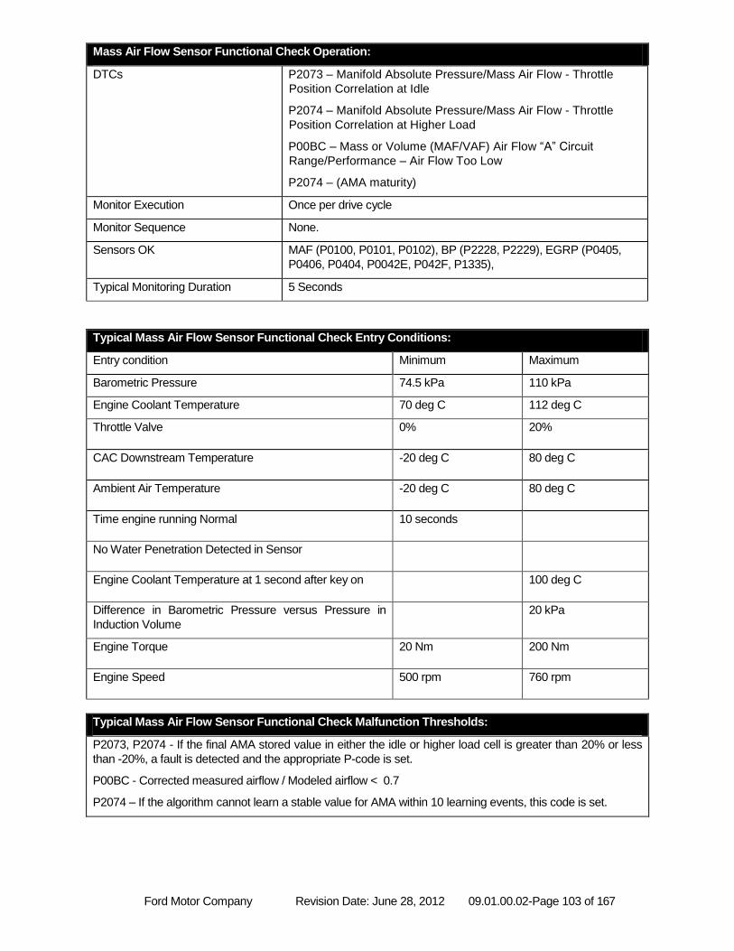
Ford Motor Company Revision Date: June 28, 2012 09.01.00.02-Page 103 of 167
Mass Air Flow Sensor Functional Check Operation:
DTCs P2073 – Manifold Absolute Pressure/Mass Air Flow - Throttle
Position Correlation at Idle
P2074 – Manifold Absolute Pressure/Mass Air Flow - Throttle
Position Correlation at Higher Load
P00BC – Mass or Volume (MAF/VAF) Air Flow “A” Circuit
Range/Performance – Air Flow Too Low
P2074 – (AMA maturity)
Monitor Execution Once per drive cycle
Monitor Sequence None.
Sensors OK MAF (P0100, P0101, P0102), BP (P2228, P2229), EGRP (P0405,
P0406, P0404, P0042E, P042F, P1335),
Typical Monitoring Duration 5 Seconds
Typical Mass Air Flow Sensor Functional Check Entry Conditions:
Entry condition Minimum Maximum
Barometric Pressure 74.5 kPa 110 kPa
Engine Coolant Temperature 70 deg C 112 deg C
Throttle Valve 0% 20%
CAC Downstream Temperature -20 deg C 80 deg C
Ambient Air Temperature -20 deg C 80 deg C
Time engine running Normal 10 seconds
No Water Penetration Detected in Sensor
Engine Coolant Temperature at 1 second after key on 100 deg C
Difference in Barometric Pressure versus Pressure in
Induction Volume
20 kPa
Engine Torque 20 Nm 200 Nm
Engine Speed 500 rpm 760 rpm
Typical Mass Air Flow Sensor Functional Check Malfunction Thresholds:
P2073, P2074 - If the final AMA stored value in either the idle or higher load cell is greater than 20% or less
than -20%, a fault is detected and the appropriate P-code is set.
P00BC - Corrected measured airflow / Modeled airflow < 0.7
P2074 – If the algorithm cannot learn a stable value for AMA within 10 learning events, this code is set.
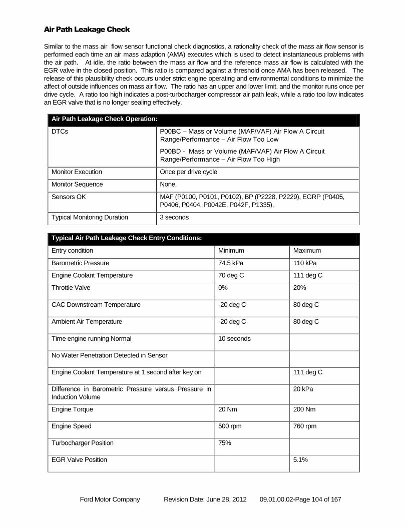
Ford Motor Company Revision Date: June 28, 2012 09.01.00.02-Page 104 of 167
Air Path Leakage Check
Similar to the mass air flow sensor functional check diagnostics, a rationality check of the mass air flow sensor is
performed each time an air mass adaption (AMA) executes which is used to detect instantaneous problems with
the air path. At idle, the ratio between the mass air flow and the reference mass air flow is calculated with the
EGR valve in the closed position. This ratio is compared against a threshold once AMA has been released. The
release of this plausibility check occurs under strict engine operating and environmental conditions to minimize the
affect of outside influences on mass air flow. The ratio has an upper and lower limit, and the monitor runs once per
drive cycle. A ratio too high indicates a post-turbocharger compressor air path leak, while a ratio too low indicates
an EGR valve that is no longer sealing effectively.
Air Path Leakage Check Operation:
DTCs P00BC – Mass or Volume (MAF/VAF) Air Flow A Circuit
Range/Performance – Air Flow Too Low
P00BD - Mass or Volume (MAF/VAF) Air Flow A Circuit
Range/Performance – Air Flow Too High
Monitor Execution Once per drive cycle
Monitor Sequence None.
Sensors OK MAF (P0100, P0101, P0102), BP (P2228, P2229), EGRP (P0405,
P0406, P0404, P0042E, P042F, P1335),
Typical Monitoring Duration 3 seconds
Typical Air Path Leakage Check Entry Conditions:
Entry condition Minimum Maximum
Barometric Pressure 74.5 kPa 110 kPa
Engine Coolant Temperature 70 deg C 111 deg C
Throttle Valve 0% 20%
CAC Downstream Temperature -20 deg C 80 deg C
Ambient Air Temperature -20 deg C 80 deg C
Time engine running Normal 10 seconds
No Water Penetration Detected in Sensor
Engine Coolant Temperature at 1 second after key on 111 deg C
Difference in Barometric Pressure versus Pressure in
Induction Volume
20 kPa
Engine Torque 20 Nm 200 Nm
Engine Speed 500 rpm 760 rpm
Turbocharger Position 75%
EGR Valve Position 5.1%
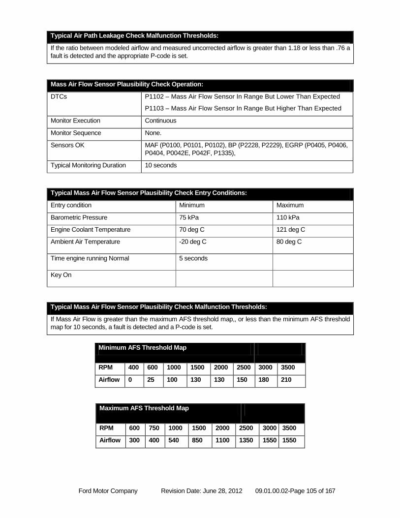
Ford Motor Company Revision Date: June 28, 2012 09.01.00.02-Page 105 of 167
Typical Air Path Leakage Check Malfunction Thresholds:
If the ratio between modeled airflow and measured uncorrected airflow is greater than 1.18 or less than .76 a
fault is detected and the appropriate P-code is set.
Mass Air Flow Sensor Plausibility Check Operation:
DTCs P1102 – Mass Air Flow Sensor In Range But Lower Than Expected
P1103 – Mass Air Flow Sensor In Range But Higher Than Expected
Monitor Execution Continuous
Monitor Sequence None.
Sensors OK MAF (P0100, P0101, P0102), BP (P2228, P2229), EGRP (P0405, P0406,
P0404, P0042E, P042F, P1335),
Typical Monitoring Duration 10 seconds
Typical Mass Air Flow Sensor Plausibility Check Entry Conditions:
Entry condition Minimum Maximum
Barometric Pressure 75 kPa 110 kPa
Engine Coolant Temperature 70 deg C 121 deg C
Ambient Air Temperature -20 deg C 80 deg C
Time engine running Normal 5 seconds
Key On
Typical Mass Air Flow Sensor Plausibility Check Malfunction Thresholds:
If Mass Air Flow is greater than the maximum AFS threshold map,, or less than the minimum AFS threshold
map for 10 seconds, a fault is detected and a P-code is set.
Minimum AFS Threshold Map
RPM 400 600 1000 1500 2000 2500 3000 3500
Airflow 0 25 100 130 130 150 180 210
Maximum AFS Threshold Map
RPM 600 750 1000 1500 2000 2500 3000 3500
Airflow 300 400 540 850 1100 1350 1550 1550
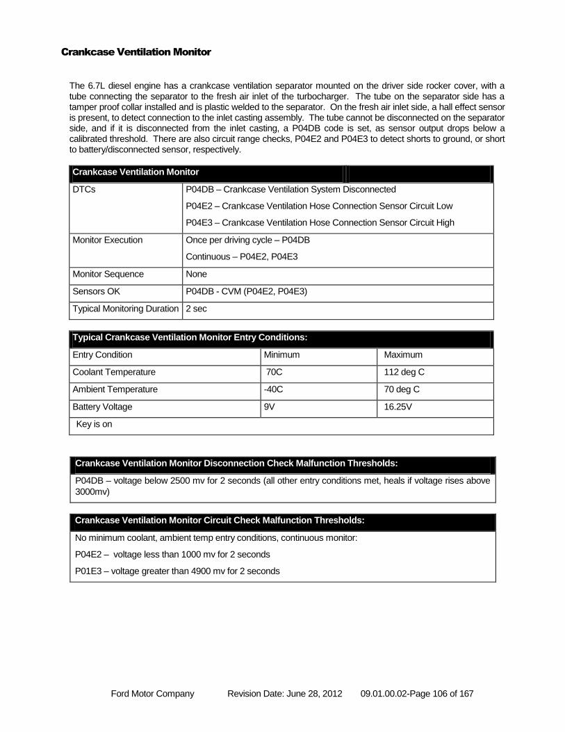
Ford Motor Company Revision Date: June 28, 2012 09.01.00.02-Page 106 of 167
Crankcase Ventilation Monitor
The 6.7L diesel engine has a crankcase ventilation separator mounted on the driver side rocker cover, with a tube connecting the separator to the fresh air inlet of the turbocharger. The tube on the separator side has a tamper proof collar installed and is plastic welded to the separator. On the fresh air inlet side, a hall effect sensor is present, to detect connection to the inlet casting assembly. The tube cannot be disconnected on the separator side, and if it is disconnected from the inlet casting, a P04DB code is set, as sensor output drops below a calibrated threshold. There are also circuit range checks, P04E2 and P04E3 to detect shorts to ground, or short to battery/disconnected sensor, respectively.
Crankcase Ventilation Monitor
DTCs P04DB – Crankcase Ventilation System Disconnected
P04E2 – Crankcase Ventilation Hose Connection Sensor Circuit Low
P04E3 – Crankcase Ventilation Hose Connection Sensor Circuit High
Monitor Execution Once per driving cycle – P04DB
Continuous – P04E2, P04E3
Monitor Sequence None
Sensors OK P04DB - CVM (P04E2, P04E3)
Typical Monitoring Duration 2 sec
Typical Crankcase Ventilation Monitor Entry Conditions:
Entry Condition Minimum Maximum
Coolant Temperature 70C 112 deg C
Ambient Temperature -40C 70 deg C
Battery Voltage 9V 16.25V
Key is on
Crankcase Ventilation Monitor Disconnection Check Malfunction Thresholds:
P04DB – voltage below 2500 mv for 2 seconds (all other entry conditions met, heals if voltage rises above
3000mv)
Crankcase Ventilation Monitor Circuit Check Malfunction Thresholds:
No minimum coolant, ambient temp entry conditions, continuous monitor:
P04E2 – voltage less than 1000 mv for 2 seconds
P01E3 – voltage greater than 4900 mv for 2 seconds
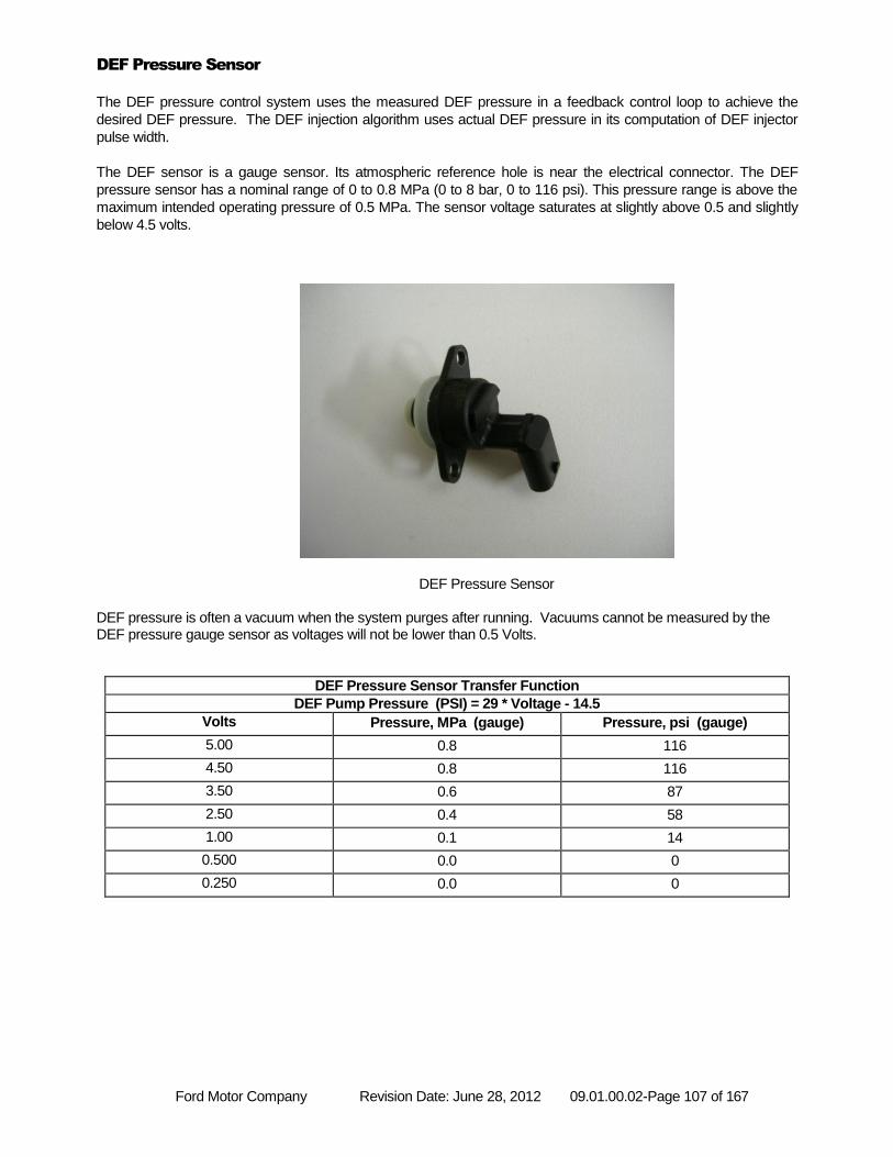
Ford Motor Company Revision Date: June 28, 2012 09.01.00.02-Page 107 of 167
DEF Pressure Sensor
The DEF pressure control system uses the measured DEF pressure in a feedback control loop to achieve the
desired DEF pressure. The DEF injection algorithm uses actual DEF pressure in its computation of DEF injector
pulse width.
The DEF sensor is a gauge sensor. Its atmospheric reference hole is near the electrical connector. The DEF
pressure sensor has a nominal range of 0 to 0.8 MPa (0 to 8 bar, 0 to 116 psi). This pressure range is above the
maximum intended operating pressure of 0.5 MPa. The sensor voltage saturates at slightly above 0.5 and slightly
below 4.5 volts.
DEF Pressure Sensor DEF pressure is often a vacuum when the system purges after running. Vacuums cannot be measured by the DEF pressure gauge sensor as voltages will not be lower than 0.5 Volts.
DEF Pressure Sensor Transfer Function
DEF Pump Pressure (PSI) = 29 * Voltage - 14.5
Volts Pressure, MPa (gauge) Pressure, psi (gauge)
5.00 0.8 116
4.50 0.8 116
3.50 0.6 87
2.50 0.4 58
1.00 0.1 14
0.500 0.0 0
0.250 0.0 0
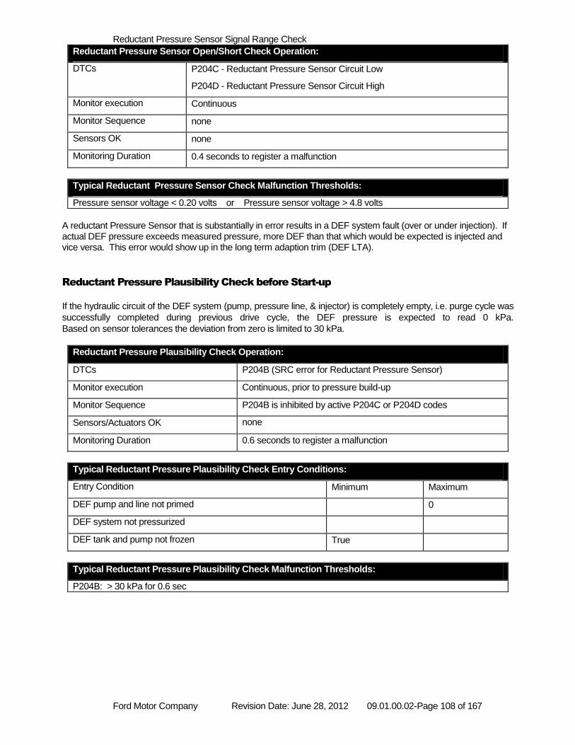
Ford Motor Company Revision Date: June 28, 2012 09.01.00.02-Page 108 of 167
Reductant Pressure Sensor Signal Range Check
Reductant Pressure Sensor Open/Short Check Operation:
DTCs P204C - Reductant Pressure Sensor Circuit Low
P204D - Reductant Pressure Sensor Circuit High
Monitor execution Continuous
Monitor Sequence none
Sensors OK none
Monitoring Duration 0.4 seconds to register a malfunction
Typical Reductant Pressure Sensor Check Malfunction Thresholds:
Pressure sensor voltage < 0.20 volts or Pressure sensor voltage > 4.8 volts
A reductant Pressure Sensor that is substantially in error results in a DEF system fault (over or under injection). If actual DEF pressure exceeds measured pressure, more DEF than that which would be expected is injected and vice versa. This error would show up in the long term adaption trim (DEF LTA).
Reductant Pressure Plausibility Check before Start-up
If the hydraulic circuit of the DEF system (pump, pressure line, & injector) is completely empty, i.e. purge cycle was
successfully completed during previous drive cycle, the DEF pressure is expected to read 0 kPa.
Based on sensor tolerances the deviation from zero is limited to 30 kPa.
Reductant Pressure Plausibility Check Operation:
DTCs P204B (SRC error for Reductant Pressure Sensor)
Monitor execution Continuous, prior to pressure build-up
Monitor Sequence P204B is inhibited by active P204C or P204D codes
Sensors/Actuators OK none
Monitoring Duration 0.6 seconds to register a malfunction
Typical Reductant Pressure Plausibility Check Entry Conditions:
Entry Condition Minimum Maximum
DEF pump and line not primed 0
DEF system not pressurized
DEF tank and pump not frozen True
Typical Reductant Pressure Plausibility Check Malfunction Thresholds:
P204B: > 30 kPa for 0.6 sec
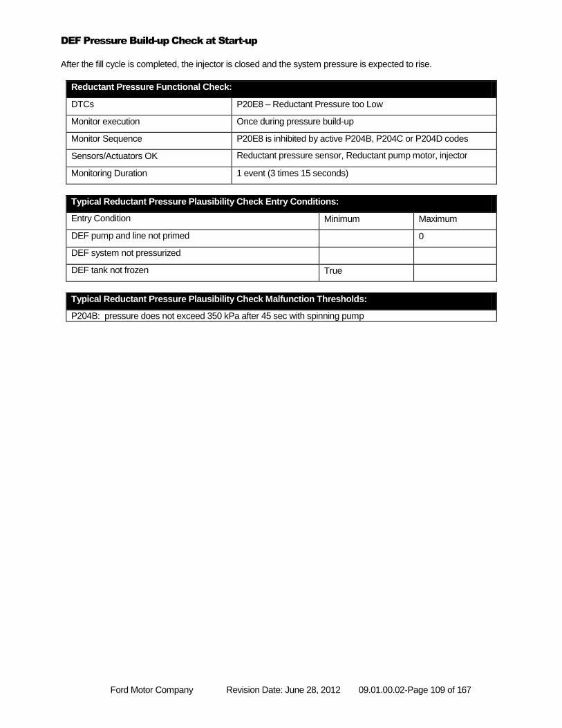
Ford Motor Company Revision Date: June 28, 2012 09.01.00.02-Page 109 of 167
DEF Pressure Build-up Check at Start-up
After the fill cycle is completed, the injector is closed and the system pressure is expected to rise.
Reductant Pressure Functional Check:
DTCs P20E8 – Reductant Pressure too Low
Monitor execution Once during pressure build-up
Monitor Sequence P20E8 is inhibited by active P204B, P204C or P204D codes
Sensors/Actuators OK Reductant pressure sensor, Reductant pump motor, injector
Monitoring Duration 1 event (3 times 15 seconds)
Typical Reductant Pressure Plausibility Check Entry Conditions:
Entry Condition Minimum Maximum
DEF pump and line not primed 0
DEF system not pressurized
DEF tank not frozen True
Typical Reductant Pressure Plausibility Check Malfunction Thresholds:
P204B: pressure does not exceed 350 kPa after 45 sec with spinning pump
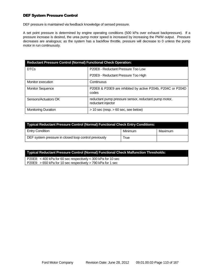
Ford Motor Company Revision Date: June 28, 2012 09.01.00.02-Page 110 of 167
DEF System Pressure Control
DEF pressure is maintained via feedback knowledge of sensed pressure.
A set point pressure is determined by engine operating conditions (500 kPa over exhaust backpressure). If a
pressure increase is desired, the urea pump motor speed is increased by increasing the PWM output. Pressure
decreases are analogous; as the system has a backflow throttle, pressure will decrease to 0 unless the pump
motor in run continuously.
Reductant Pressure Control (Normal) Functional Check Operation:
DTCs P20E8 - Reductant Pressure Too Low
P20E9 - Reductant Pressure Too High
Monitor execution Continuous
Monitor Sequence P20E8 & P20E9 are inhibited by active P204b, P204C or P204D
codes
Sensors/Actuators OK reductant pump pressure sensor, reductant pump motor, reductant injector
Monitoring Duration > 10 sec (resp. > 60 sec, see below)
Typical Reductant Pressure Control (Normal) Functional Check Entry Conditions:
Entry Condition Minimum Maximum
DEF system pressure in closed loop control previously True
Typical Reductant Pressure Control (Normal) Functional Check Malfunction Thresholds:
P20E8: < 400 kPa for 60 sec respectively < 300 kPa for 10 sec P20E9: > 650 kPa for 10 sec respectively > 790 kPa for 1 sec
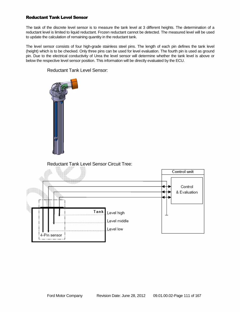
Ford Motor Company Revision Date: June 28, 2012 09.01.00.02-Page 111 of 167
Reductant Tank Level Sensor
The task of the discrete level sensor is to measure the tank level at 3 different heights. The determination of a
reductant level is limited to liquid reductant. Frozen reductant cannot be detected. The measured level will be used
to update the calculation of remaining quantity in the reductant tank.
The level sensor consists of four high-grade stainless steel pins. The length of each pin defines the tank level
(height) which is to be checked. Only three pins can be used for level evaluation. The fourth pin is used as ground
pin. Due to the electrical conductivity of Urea the level sensor will determine whether the tank level is above or
below the respective level sensor position. This information will be directly evaluated by the ECU.
Reductant Tank Level Sensor:
Reductant Tank Level Sensor Circuit Tree:
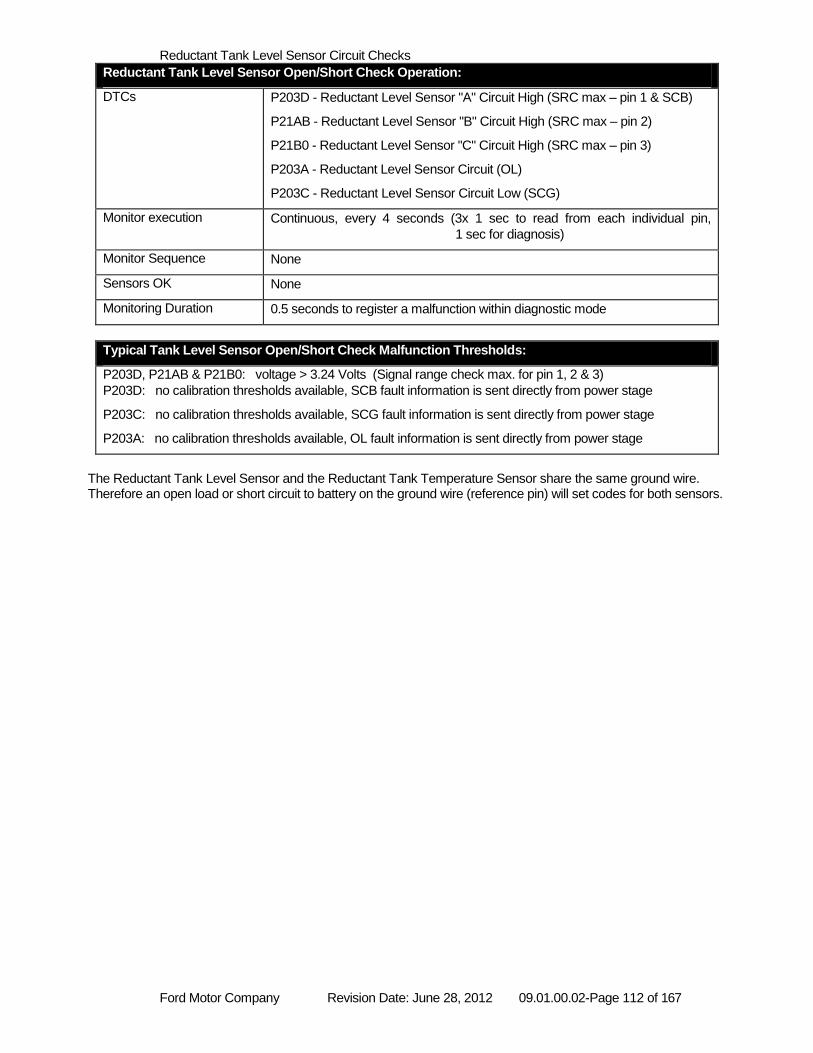
Ford Motor Company Revision Date: June 28, 2012 09.01.00.02-Page 112 of 167
Reductant Tank Level Sensor Circuit Checks
Reductant Tank Level Sensor Open/Short Check Operation:
DTCs P203D - Reductant Level Sensor "A" Circuit High (SRC max – pin 1 & SCB)
P21AB - Reductant Level Sensor "B" Circuit High (SRC max – pin 2)
P21B0 - Reductant Level Sensor "C" Circuit High (SRC max – pin 3)
P203A - Reductant Level Sensor Circuit (OL)
P203C - Reductant Level Sensor Circuit Low (SCG)
Monitor execution Continuous, every 4 seconds (3x 1 sec to read from each individual pin,
1 sec for diagnosis)
Monitor Sequence None
Sensors OK None
Monitoring Duration 0.5 seconds to register a malfunction within diagnostic mode
Typical Tank Level Sensor Open/Short Check Malfunction Thresholds:
P203D, P21AB & P21B0: voltage > 3.24 Volts (Signal range check max. for pin 1, 2 & 3)
P203D: no calibration thresholds available, SCB fault information is sent directly from power stage
P203C: no calibration thresholds available, SCG fault information is sent directly from power stage
P203A: no calibration thresholds available, OL fault information is sent directly from power stage
The Reductant Tank Level Sensor and the Reductant Tank Temperature Sensor share the same ground wire. Therefore an open load or short circuit to battery on the ground wire (reference pin) will set codes for both sensors.
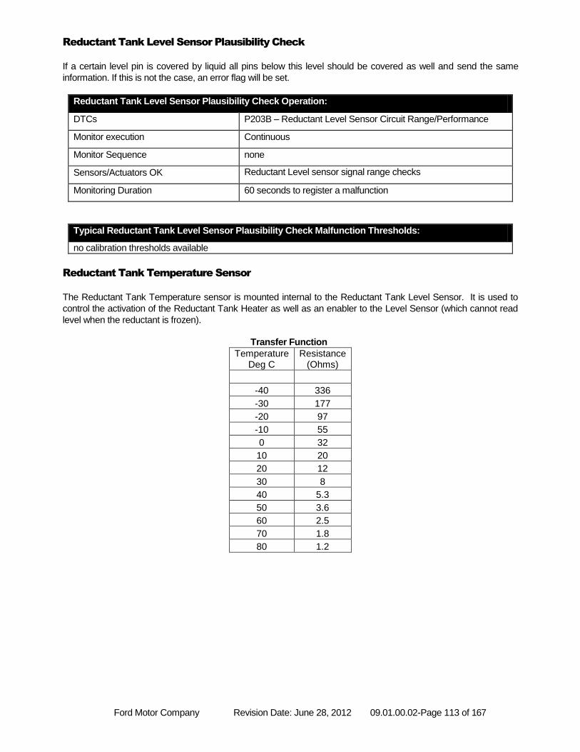
Ford Motor Company Revision Date: June 28, 2012 09.01.00.02-Page 113 of 167
Reductant Tank Level Sensor Plausibility Check
If a certain level pin is covered by liquid all pins below this level should be covered as well and send the same
information. If this is not the case, an error flag will be set.
Reductant Tank Level Sensor Plausibility Check Operation:
DTCs P203B – Reductant Level Sensor Circuit Range/Performance
Monitor execution Continuous
Monitor Sequence none
Sensors/Actuators OK Reductant Level sensor signal range checks
Monitoring Duration 60 seconds to register a malfunction
Typical Reductant Tank Level Sensor Plausibility Check Malfunction Thresholds:
no calibration thresholds available
Reductant Tank Temperature Sensor
The Reductant Tank Temperature sensor is mounted internal to the Reductant Tank Level Sensor. It is used to
control the activation of the Reductant Tank Heater as well as an enabler to the Level Sensor (which cannot read
level when the reductant is frozen).
Transfer Function
Temperature Deg C
Resistance (Ohms)
-40 336
-30 177
-20 97
-10 55
0 32
10 20
20 12
30 8
40 5.3
50 3.6
60 2.5
70 1.8
80 1.2
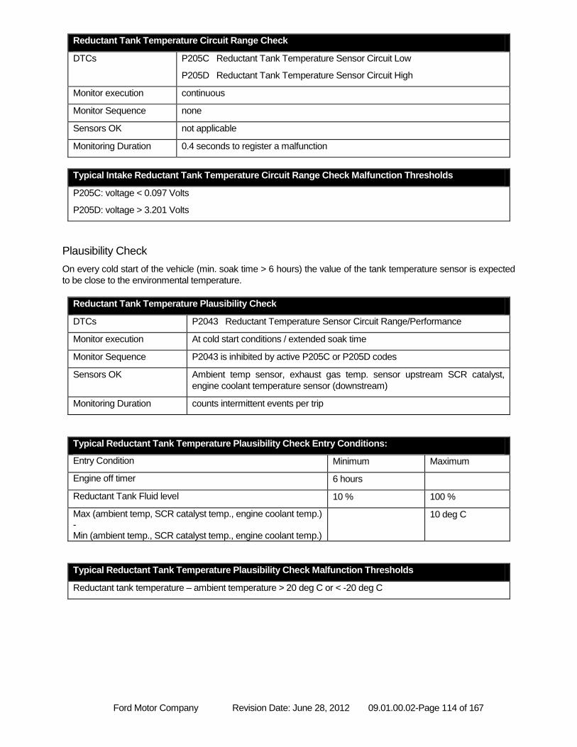
Ford Motor Company Revision Date: June 28, 2012 09.01.00.02-Page 114 of 167
Reductant Tank Temperature Circuit Range Check
DTCs P205C Reductant Tank Temperature Sensor Circuit Low
P205D Reductant Tank Temperature Sensor Circuit High
Monitor execution continuous
Monitor Sequence none
Sensors OK not applicable
Monitoring Duration 0.4 seconds to register a malfunction
Typical Intake Reductant Tank Temperature Circuit Range Check Malfunction Thresholds
P205C: voltage < 0.097 Volts
P205D: voltage > 3.201 Volts
Plausibility Check
On every cold start of the vehicle (min. soak time > 6 hours) the value of the tank temperature sensor is expected
to be close to the environmental temperature.
Reductant Tank Temperature Plausibility Check
DTCs P2043 Reductant Temperature Sensor Circuit Range/Performance
Monitor execution At cold start conditions / extended soak time
Monitor Sequence P2043 is inhibited by active P205C or P205D codes
Sensors OK Ambient temp sensor, exhaust gas temp. sensor upstream SCR catalyst,
engine coolant temperature sensor (downstream)
Monitoring Duration counts intermittent events per trip
Typical Reductant Tank Temperature Plausibility Check Entry Conditions:
Entry Condition Minimum Maximum
Engine off timer 6 hours
Reductant Tank Fluid level 10 % 100 %
Max (ambient temp, SCR catalyst temp., engine coolant temp.) - Min (ambient temp., SCR catalyst temp., engine coolant temp.)
10 deg C
Typical Reductant Tank Temperature Plausibility Check Malfunction Thresholds
Reductant tank temperature – ambient temperature > 20 deg C or < -20 deg C
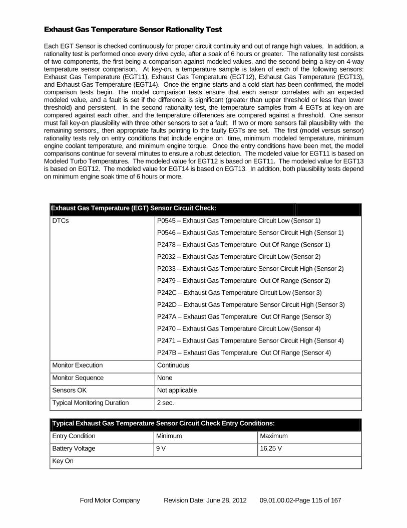
Ford Motor Company Revision Date: June 28, 2012 09.01.00.02-Page 115 of 167
Exhaust Gas Temperature Sensor Rationality Test
Each EGT Sensor is checked continuously for proper circuit continuity and out of range high values. In addition, a rationality test is performed once every drive cycle, after a soak of 6 hours or greater. The rationality test consists of two components, the first being a comparison against modeled values, and the second being a key-on 4-way temperature sensor comparison. At key-on, a temperature sample is taken of each of the following sensors: Exhaust Gas Temperature (EGT11), Exhaust Gas Temperature (EGT12), Exhaust Gas Temperature (EGT13), and Exhaust Gas Temperature (EGT14). Once the engine starts and a cold start has been confirmed, the model comparison tests begin. The model comparison tests ensure that each sensor correlates with an expected modeled value, and a fault is set if the difference is significant (greater than upper threshold or less than lower threshold) and persistent. In the second rationality test, the temperature samples from 4 EGTs at key-on are compared against each other, and the temperature differences are compared against a threshold. One sensor must fail key-on plausibility with three other sensors to set a fault. If two or more sensors fail plausibility with the remaining sensors,, then appropriate faults pointing to the faulty EGTs are set. The first (model versus sensor) rationality tests rely on entry conditions that include engine on time, minimum modeled temperature, minimum engine coolant temperature, and minimum engine torque. Once the entry conditions have been met, the model comparisons continue for several minutes to ensure a robust detection. The modeled value for EGT11 is based on Modeled Turbo Temperatures. The modeled value for EGT12 is based on EGT11. The modeled value for EGT13 is based on EGT12. The modeled value for EGT14 is based on EGT13. In addition, both plausibility tests depend on minimum engine soak time of 6 hours or more.
Exhaust Gas Temperature (EGT) Sensor Circuit Check:
DTCs P0545 – Exhaust Gas Temperature Circuit Low (Sensor 1)
P0546 – Exhaust Gas Temperature Sensor Circuit High (Sensor 1)
P2478 – Exhaust Gas Temperature Out Of Range (Sensor 1)
P2032 – Exhaust Gas Temperature Circuit Low (Sensor 2)
P2033 – Exhaust Gas Temperature Sensor Circuit High (Sensor 2)
P2479 – Exhaust Gas Temperature Out Of Range (Sensor 2)
P242C – Exhaust Gas Temperature Circuit Low (Sensor 3)
P242D – Exhaust Gas Temperature Sensor Circuit High (Sensor 3)
P247A – Exhaust Gas Temperature Out Of Range (Sensor 3)
P2470 – Exhaust Gas Temperature Circuit Low (Sensor 4)
P2471 – Exhaust Gas Temperature Sensor Circuit High (Sensor 4)
P247B – Exhaust Gas Temperature Out Of Range (Sensor 4)
Monitor Execution Continuous
Monitor Sequence None
Sensors OK Not applicable
Typical Monitoring Duration 2 sec.
Typical Exhaust Gas Temperature Sensor Circuit Check Entry Conditions:
Entry Condition Minimum Maximum
Battery Voltage 9 V 16.25 V
Key On
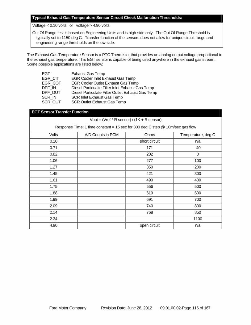
Ford Motor Company Revision Date: June 28, 2012 09.01.00.02-Page 116 of 167
Typical Exhaust Gas Temperature Sensor Circuit Check Malfunction Thresholds:
Voltage < 0.10 volts or voltage > 4.90 volts
Out Of Range test is based on Engineering Units and is high-side only. The Out Of Range Threshold is
typically set to 1150 deg C. Transfer function of the sensors does not allow for unique circuit range and
engineering range thresholds on the low-side.
The Exhaust Gas Temperature Sensor is a PTC Thermistor that provides an analog output voltage proportional to the exhaust gas temperature. This EGT sensor is capable of being used anywhere in the exhaust gas stream. Some possible applications are listed below:
EGT Exhaust Gas Temp EGR_CIT EGR Cooler Inlet Exhaust Gas Temp EGR_COT EGR Cooler Outlet Exhaust Gas Temp DPF_IN Diesel Particualte Filter Inlet Exhaust Gas Temp DPF_OUT Diesel Particulate Filter Outlet Exhaust Gas Temp SCR_IN SCR Inlet Exhaust Gas Temp SCR_OUT SCR Outlet Exhaust Gas Temp
EGT Sensor Transfer Function
Vout = (Vref * R sensor) / (1K + R sensor)
Response Time: 1 time constant = 15 sec for 300 deg C step @ 10m/sec gas flow
Volts A/D Counts in PCM Ohms Temperature, deg C
0.10 short circuit n/a
0.71 171 -40
0.82 202 0
1.06 277 100
1.27 350 200
1.45 421 300
1.61 490 400
1.75 556 500
1.88 619 600
1.99 691 700
2.09 740 800
2.14 768 850
2.34 1100
4.90 open circuit n/a
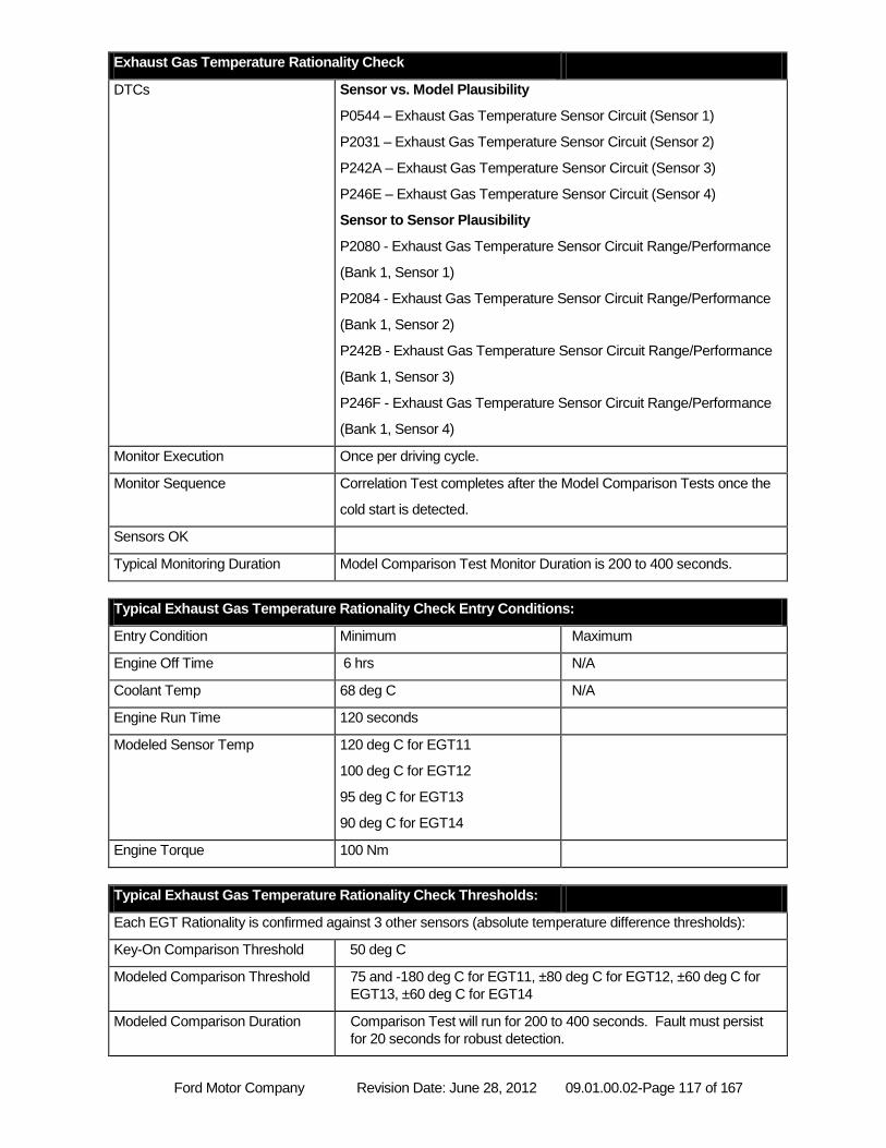
Ford Motor Company Revision Date: June 28, 2012 09.01.00.02-Page 117 of 167
Exhaust Gas Temperature Rationality Check
DTCs Sensor vs. Model Plausibility
P0544 – Exhaust Gas Temperature Sensor Circuit (Sensor 1)
P2031 – Exhaust Gas Temperature Sensor Circuit (Sensor 2)
P242A – Exhaust Gas Temperature Sensor Circuit (Sensor 3)
P246E – Exhaust Gas Temperature Sensor Circuit (Sensor 4)
Sensor to Sensor Plausibility
P2080 - Exhaust Gas Temperature Sensor Circuit Range/Performance
(Bank 1, Sensor 1)
P2084 - Exhaust Gas Temperature Sensor Circuit Range/Performance
(Bank 1, Sensor 2)
P242B - Exhaust Gas Temperature Sensor Circuit Range/Performance
(Bank 1, Sensor 3)
P246F - Exhaust Gas Temperature Sensor Circuit Range/Performance
(Bank 1, Sensor 4)
Monitor Execution Once per driving cycle.
Monitor Sequence Correlation Test completes after the Model Comparison Tests once the
cold start is detected.
Sensors OK
Typical Monitoring Duration Model Comparison Test Monitor Duration is 200 to 400 seconds.
Typical Exhaust Gas Temperature Rationality Check Entry Conditions:
Entry Condition Minimum Maximum
Engine Off Time 6 hrs N/A
Coolant Temp 68 deg C N/A
Engine Run Time 120 seconds
Modeled Sensor Temp 120 deg C for EGT11
100 deg C for EGT12
95 deg C for EGT13
90 deg C for EGT14
Engine Torque 100 Nm
Typical Exhaust Gas Temperature Rationality Check Thresholds:
Each EGT Rationality is confirmed against 3 other sensors (absolute temperature difference thresholds):
Key-On Comparison Threshold 50 deg C
Modeled Comparison Threshold 75 and -180 deg C for EGT11, ±80 deg C for EGT12, ±60 deg C for
EGT13, ±60 deg C for EGT14
Modeled Comparison Duration Comparison Test will run for 200 to 400 seconds. Fault must persist
for 20 seconds for robust detection.
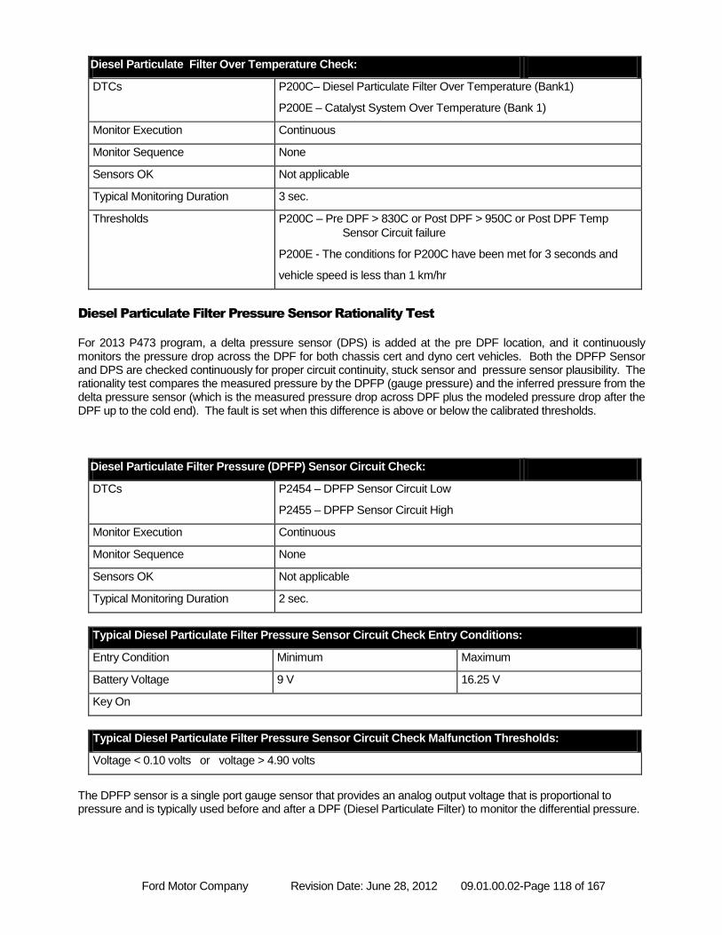
Ford Motor Company Revision Date: June 28, 2012 09.01.00.02-Page 118 of 167
Diesel Particulate Filter Over Temperature Check:
DTCs P200C– Diesel Particulate Filter Over Temperature (Bank1)
P200E – Catalyst System Over Temperature (Bank 1)
Monitor Execution Continuous
Monitor Sequence None
Sensors OK Not applicable
Typical Monitoring Duration 3 sec.
Thresholds P200C – Pre DPF > 830C or Post DPF > 950C or Post DPF Temp
Sensor Circuit failure
P200E - The conditions for P200C have been met for 3 seconds and
vehicle speed is less than 1 km/hr
Diesel Particulate Filter Pressure Sensor Rationality Test
For 2013 P473 program, a delta pressure sensor (DPS) is added at the pre DPF location, and it continuously monitors the pressure drop across the DPF for both chassis cert and dyno cert vehicles. Both the DPFP Sensor and DPS are checked continuously for proper circuit continuity, stuck sensor and pressure sensor plausibility. The rationality test compares the measured pressure by the DPFP (gauge pressure) and the inferred pressure from the delta pressure sensor (which is the measured pressure drop across DPF plus the modeled pressure drop after the DPF up to the cold end). The fault is set when this difference is above or below the calibrated thresholds.
Diesel Particulate Filter Pressure (DPFP) Sensor Circuit Check:
DTCs P2454 – DPFP Sensor Circuit Low
P2455 – DPFP Sensor Circuit High
Monitor Execution Continuous
Monitor Sequence None
Sensors OK Not applicable
Typical Monitoring Duration 2 sec.
Typical Diesel Particulate Filter Pressure Sensor Circuit Check Entry Conditions:
Entry Condition Minimum Maximum
Battery Voltage 9 V 16.25 V
Key On
Typical Diesel Particulate Filter Pressure Sensor Circuit Check Malfunction Thresholds:
Voltage < 0.10 volts or voltage > 4.90 volts
The DPFP sensor is a single port gauge sensor that provides an analog output voltage that is proportional to pressure and is typically used before and after a DPF (Diesel Particulate Filter) to monitor the differential pressure.
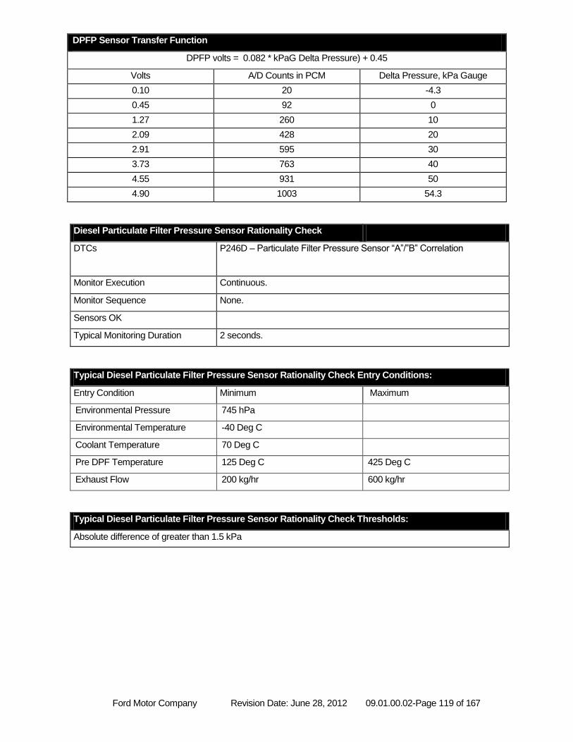
Ford Motor Company Revision Date: June 28, 2012 09.01.00.02-Page 119 of 167
DPFP Sensor Transfer Function
DPFP volts = 0.082 * kPaG Delta Pressure) + 0.45
Volts A/D Counts in PCM Delta Pressure, kPa Gauge
0.10 20 -4.3
0.45 92 0
1.27 260 10
2.09 428 20
2.91 595 30
3.73 763 40
4.55 931 50
4.90 1003 54.3
Diesel Particulate Filter Pressure Sensor Rationality Check
DTCs P246D – Particulate Filter Pressure Sensor “A”/”B” Correlation
Monitor Execution Continuous.
Monitor Sequence None.
Sensors OK
Typical Monitoring Duration 2 seconds.
Typical Diesel Particulate Filter Pressure Sensor Rationality Check Entry Conditions:
Entry Condition Minimum Maximum
Environmental Pressure 745 hPa
Environmental Temperature -40 Deg C
Coolant Temperature 70 Deg C
Pre DPF Temperature 125 Deg C 425 Deg C
Exhaust Flow 200 kg/hr 600 kg/hr
Typical Diesel Particulate Filter Pressure Sensor Rationality Check Thresholds:
Absolute difference of greater than 1.5 kPa
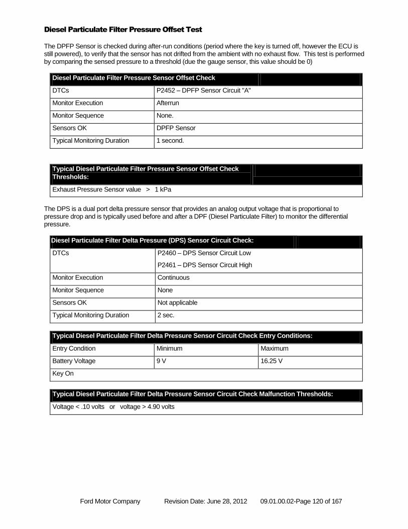
Ford Motor Company Revision Date: June 28, 2012 09.01.00.02-Page 120 of 167
Diesel Particulate Filter Pressure Offset Test
The DPFP Sensor is checked during after-run conditions (period where the key is turned off, however the ECU is still powered), to verify that the sensor has not drifted from the ambient with no exhaust flow. This test is performed by comparing the sensed pressure to a threshold (due the gauge sensor, this value should be 0)
Diesel Particulate Filter Pressure Sensor Offset Check
DTCs P2452 – DPFP Sensor Circuit "A"
Monitor Execution Afterrun
Monitor Sequence None.
Sensors OK DPFP Sensor
Typical Monitoring Duration 1 second.
Typical Diesel Particulate Filter Pressure Sensor Offset Check
Thresholds:
Exhaust Pressure Sensor value > 1 kPa
The DPS is a dual port delta pressure sensor that provides an analog output voltage that is proportional to pressure drop and is typically used before and after a DPF (Diesel Particulate Filter) to monitor the differential pressure.
Diesel Particulate Filter Delta Pressure (DPS) Sensor Circuit Check:
DTCs P2460 – DPS Sensor Circuit Low
P2461 – DPS Sensor Circuit High
Monitor Execution Continuous
Monitor Sequence None
Sensors OK Not applicable
Typical Monitoring Duration 2 sec.
Typical Diesel Particulate Filter Delta Pressure Sensor Circuit Check Entry Conditions:
Entry Condition Minimum Maximum
Battery Voltage 9 V 16.25 V
Key On
Typical Diesel Particulate Filter Delta Pressure Sensor Circuit Check Malfunction Thresholds:
Voltage < .10 volts or voltage > 4.90 volts
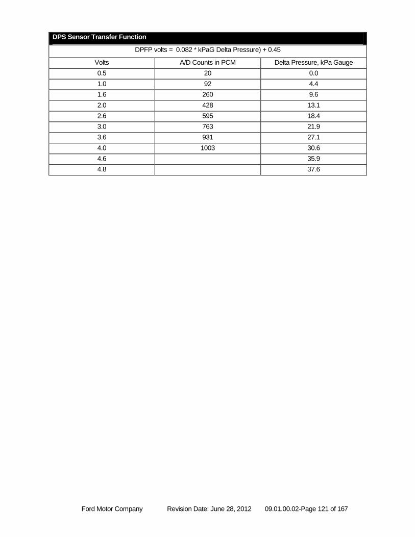
Ford Motor Company Revision Date: June 28, 2012 09.01.00.02-Page 121 of 167
DPS Sensor Transfer Function
DPFP volts = 0.082 * kPaG Delta Pressure) + 0.45
Volts A/D Counts in PCM Delta Pressure, kPa Gauge
0.5 20 0.0
1.0 92 4.4
1.6 260 9.6
2.0 428 13.1
2.6 595 18.4
3.0 763 21.9
3.6 931 27.1
4.0 1003 30.6
4.6 35.9
4.8 37.6
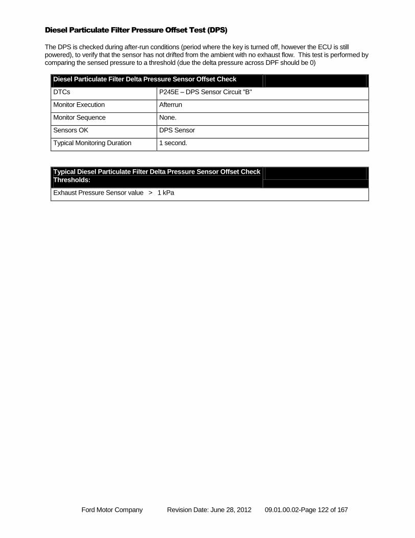
Ford Motor Company Revision Date: June 28, 2012 09.01.00.02-Page 122 of 167
Diesel Particulate Filter Pressure Offset Test (DPS)
The DPS is checked during after-run conditions (period where the key is turned off, however the ECU is still powered), to verify that the sensor has not drifted from the ambient with no exhaust flow. This test is performed by comparing the sensed pressure to a threshold (due the delta pressure across DPF should be 0)
Diesel Particulate Filter Delta Pressure Sensor Offset Check
DTCs P245E – DPS Sensor Circuit "B"
Monitor Execution Afterrun
Monitor Sequence None.
Sensors OK DPS Sensor
Typical Monitoring Duration 1 second.
Typical Diesel Particulate Filter Delta Pressure Sensor Offset Check
Thresholds:
Exhaust Pressure Sensor value > 1 kPa
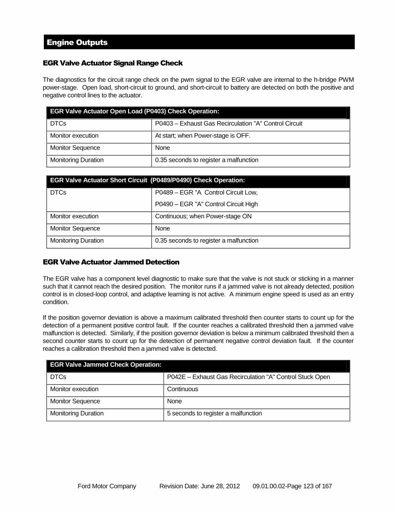
Ford Motor Company Revision Date: June 28, 2012 09.01.00.02-Page 123 of 167
Engine Outputs
EGR Valve Actuator Signal Range Check
The diagnostics for the circuit range check on the pwm signal to the EGR valve are internal to the h-bridge PWM
power-stage. Open load, short-circuit to ground, and short-circuit to battery are detected on both the positive and
negative control lines to the actuator.
EGR Valve Actuator Open Load (P0403) Check Operation:
DTCs P0403 – Exhaust Gas Recirculation "A" Control Circuit
Monitor execution At start; when Power-stage is OFF.
Monitor Sequence None
Monitoring Duration 0.35 seconds to register a malfunction
EGR Valve Actuator Short Circuit (P0489/P0490) Check Operation:
DTCs P0489 – EGR "A Control Circuit Low,
P0490 – EGR "A" Control Circuit High
Monitor execution Continuous; when Power-stage ON
Monitor Sequence None
Monitoring Duration 0.35 seconds to register a malfunction
EGR Valve Actuator Jammed Detection
The EGR valve has a component level diagnostic to make sure that the valve is not stuck or sticking in a manner
such that it cannot reach the desired position. The monitor runs if a jammed valve is not already detected, position
control is in closed-loop control, and adaptive learning is not active. A minimum engine speed is used as an entry
condition.
If the position governor deviation is above a maximum calibrated threshold then counter starts to count up for the
detection of a permanent positive control fault. If the counter reaches a calibrated threshold then a jammed valve
malfunction is detected. Similarly, if the position governor deviation is below a minimum calibrated threshold then a
second counter starts to count up for the detection of permanent negative control deviation fault. If the counter
reaches a calibration threshold then a jammed valve is detected.
EGR Valve Jammed Check Operation:
DTCs P042E – Exhaust Gas Recirculation "A" Control Stuck Open
Monitor execution Continuous
Monitor Sequence None
Monitoring Duration 5 seconds to register a malfunction
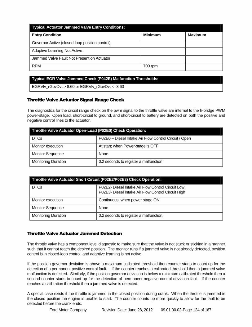
Ford Motor Company Revision Date: June 28, 2012 09.01.00.02-Page 124 of 167
Typical Actuator Jammed Valve Entry Conditions:
Entry Condition Minimum Maximum
Governor Active (closed-loop position control)
Adaptive Learning Not Active
Jammed Valve Fault Not Present on Actuator
RPM 700 rpm
Typical EGR Valve Jammed Check (P042E) Malfunction Thresholds:
EGRVlv_rGovDvt > 8.60 or EGRVlv_rGovDvt < -8.60
Throttle Valve Actuator Signal Range Check
The diagnostics for the circuit range check on the pwm signal to the throttle valve are internal to the h-bridge PWM
power-stage. Open load, short-circuit to ground, and short-circuit to battery are detected on both the positive and
negative control lines to the actuator.
Throttle Valve Actuator Open-Load (P02E0) Check Operation:
DTCs P02E0 – Diesel Intake Air Flow Control Circuit / Open
Monitor execution At start; when Power-stage is OFF.
Monitor Sequence None
Monitoring Duration 0.2 seconds to register a malfunction
Throttle Valve Actuator Short Circuit (P02E2/P02E3) Check Operation:
DTCs P02E2- Diesel Intake Air Flow Control Circuit Low;
P02E3- Diesel Intake Air Flow Control Circuit High
Monitor execution Continuous; when power stage ON
Monitor Sequence None
Monitoring Duration 0.2 seconds to register a malfunction.
Throttle Valve Actuator Jammed Detection
The throttle valve has a component level diagnostic to make sure that the valve is not stuck or sticking in a manner
such that it cannot reach the desired position. The monitor runs if a jammed valve is not already detected, position
control is in closed-loop control, and adaptive learning is not active.
If the position governor deviation is above a maximum calibrated threshold then counter starts to count up for the
detection of a permanent positive control fault. . If the counter reaches a calibrated threshold then a jammed valve
malfunction is detected. Similarly, if the position governor deviation is below a minimum calibrated threshold then a
second counter starts to count up for the detection of permanent negative control deviation fault. If the counter
reaches a calibration threshold then a jammed valve is detected.
A special case exists if the throttle is jammed in the closed position during crank. When the throttle is jammed in
the closed position the engine is unable to start. The counter counts up more quickly to allow for the fault to be
detected before the crank ends.
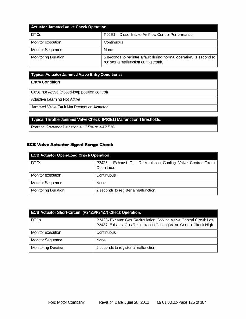
Ford Motor Company Revision Date: June 28, 2012 09.01.00.02-Page 125 of 167
Actuator Jammed Valve Check Operation:
DTCs P02E1 – Diesel Intake Air Flow Control Performance,
Monitor execution Continuous
Monitor Sequence None
Monitoring Duration 5 seconds to register a fault during normal operation. 1 second to
register a malfunction during crank.
Typical Actuator Jammed Valve Entry Conditions:
Entry Condition
Governor Active (closed-loop position control)
Adaptive Learning Not Active
Jammed Valve Fault Not Present on Actuator
Typical Throttle Jammed Valve Check (P02E1) Malfunction Thresholds:
Position Governor Deviation > 12.5% or <-12.5 %
ECB Valve Actuator Signal Range Check
ECB Actuator Open-Load Check Operation:
DTCs P2425 - Exhaust Gas Recirculation Cooling Valve Control Circuit
Open Load
Monitor execution Continuous;
Monitor Sequence None
Monitoring Duration 2 seconds to register a malfunction
ECB Actuator Short-Circuit (P2426/P2427) Check Operation:
DTCs P2426- Exhaust Gas Recirculation Cooling Valve Control Circuit Low,
P2427- Exhaust Gas Recirculation Cooling Valve Control Circuit High
Monitor execution Continuous;
Monitor Sequence None
Monitoring Duration 2 seconds to register a malfunction.
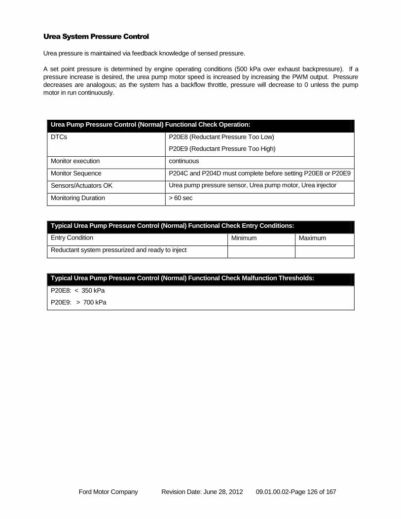
Ford Motor Company Revision Date: June 28, 2012 09.01.00.02-Page 126 of 167
Urea System Pressure Control
Urea pressure is maintained via feedback knowledge of sensed pressure.
A set point pressure is determined by engine operating conditions (500 kPa over exhaust backpressure). If a
pressure increase is desired, the urea pump motor speed is increased by increasing the PWM output. Pressure
decreases are analogous; as the system has a backflow throttle, pressure will decrease to 0 unless the pump
motor in run continuously.
Urea Pump Pressure Control (Normal) Functional Check Operation:
DTCs P20E8 (Reductant Pressure Too Low)
P20E9 (Reductant Pressure Too High)
Monitor execution continuous
Monitor Sequence P204C and P204D must complete before setting P20E8 or P20E9
Sensors/Actuators OK Urea pump pressure sensor, Urea pump motor, Urea injector
Monitoring Duration > 60 sec
Typical Urea Pump Pressure Control (Normal) Functional Check Entry Conditions:
Entry Condition Minimum Maximum
Reductant system pressurized and ready to inject
Typical Urea Pump Pressure Control (Normal) Functional Check Malfunction Thresholds:
P20E8: < 350 kPa
P20E9: > 700 kPa
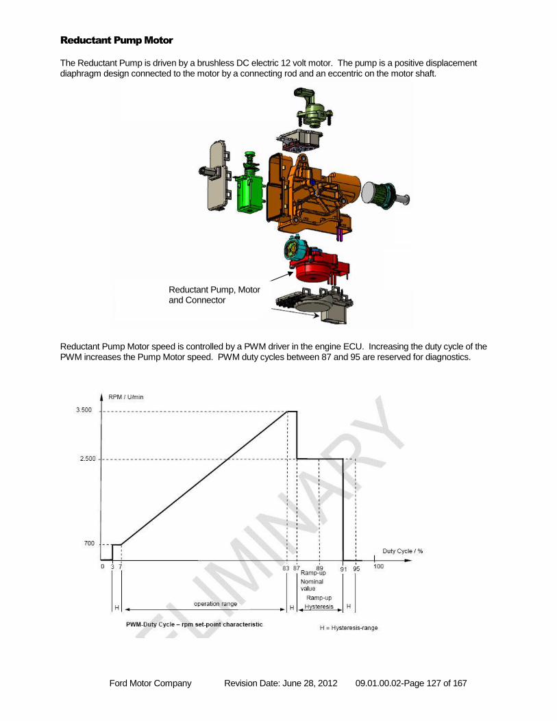
Ford Motor Company Revision Date: June 28, 2012 09.01.00.02-Page 127 of 167
Reductant Pump Motor
The Reductant Pump is driven by a brushless DC electric 12 volt motor. The pump is a positive displacement diaphragm design connected to the motor by a connecting rod and an eccentric on the motor shaft.
Reductant Pump Motor speed is controlled by a PWM driver in the engine ECU. Increasing the duty cycle of the PWM increases the Pump Motor speed. PWM duty cycles between 87 and 95 are reserved for diagnostics.
Reductant Pump, Motor and Connector
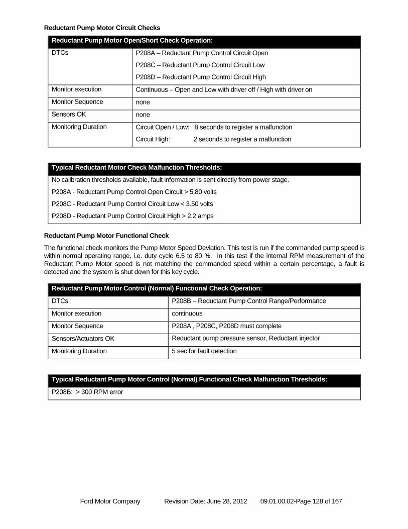
Ford Motor Company Revision Date: June 28, 2012 09.01.00.02-Page 128 of 167
Reductant Pump Motor Circuit Checks
Reductant Pump Motor Open/Short Check Operation:
DTCs P208A – Reductant Pump Control Circuit Open
P208C – Reductant Pump Control Circuit Low
P208D – Reductant Pump Control Circuit High
Monitor execution Continuous – Open and Low with driver off / High with driver on
Monitor Sequence none
Sensors OK none
Monitoring Duration Circuit Open / Low: 8 seconds to register a malfunction
Circuit High: 2 seconds to register a malfunction
Typical Reductant Motor Check Malfunction Thresholds:
No calibration thresholds available, fault information is sent directly from power stage.
P208A - Reductant Pump Control Open Circuit > 5.80 volts
P208C - Reductant Pump Control Circuit Low < 3.50 volts
P208D - Reductant Pump Control Circuit High > 2.2 amps
Reductant Pump Motor Functional Check
The functional check monitors the Pump Motor Speed Deviation. This test is run if the commanded pump speed is
within normal operating range, i.e. duty cycle 6.5 to 80 %. In this test if the internal RPM measurement of the
Reductant Pump Motor speed is not matching the commanded speed within a certain percentage, a fault is
detected and the system is shut down for this key cycle.
Reductant Pump Motor Control (Normal) Functional Check Operation:
DTCs P208B – Reductant Pump Control Range/Performance
Monitor execution continuous
Monitor Sequence P208A , P208C, P208D must complete
Sensors/Actuators OK Reductant pump pressure sensor, Reductant injector
Monitoring Duration 5 sec for fault detection
Typical Reductant Pump Motor Control (Normal) Functional Check Malfunction Thresholds:
P208B: > 300 RPM error
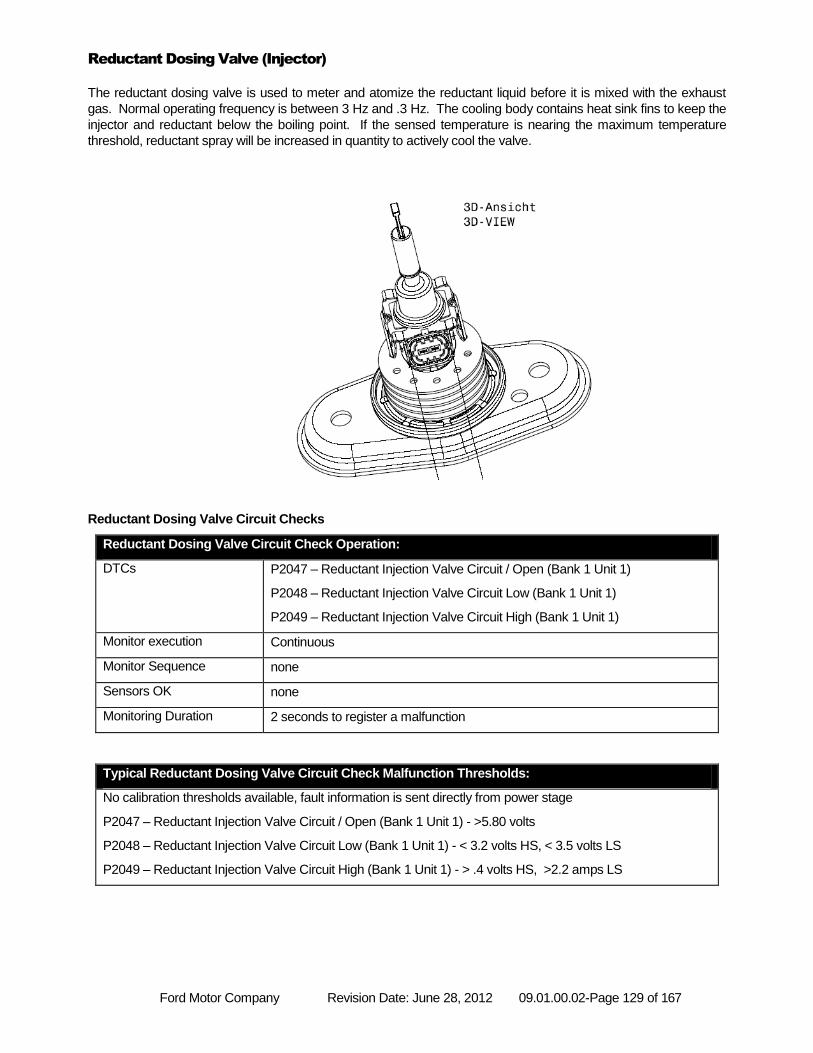
Ford Motor Company Revision Date: June 28, 2012 09.01.00.02-Page 129 of 167
Reductant Dosing Valve (Injector)
The reductant dosing valve is used to meter and atomize the reductant liquid before it is mixed with the exhaust
gas. Normal operating frequency is between 3 Hz and .3 Hz. The cooling body contains heat sink fins to keep the
injector and reductant below the boiling point. If the sensed temperature is nearing the maximum temperature
threshold, reductant spray will be increased in quantity to actively cool the valve.
Reductant Dosing Valve Circuit Checks
Reductant Dosing Valve Circuit Check Operation:
DTCs P2047 – Reductant Injection Valve Circuit / Open (Bank 1 Unit 1)
P2048 – Reductant Injection Valve Circuit Low (Bank 1 Unit 1)
P2049 – Reductant Injection Valve Circuit High (Bank 1 Unit 1)
Monitor execution Continuous
Monitor Sequence none
Sensors OK none
Monitoring Duration 2 seconds to register a malfunction
Typical Reductant Dosing Valve Circuit Check Malfunction Thresholds:
No calibration thresholds available, fault information is sent directly from power stage
P2047 – Reductant Injection Valve Circuit / Open (Bank 1 Unit 1) - >5.80 volts
P2048 – Reductant Injection Valve Circuit Low (Bank 1 Unit 1) - < 3.2 volts HS, < 3.5 volts LS
P2049 – Reductant Injection Valve Circuit High (Bank 1 Unit 1) - > .4 volts HS, >2.2 amps LS
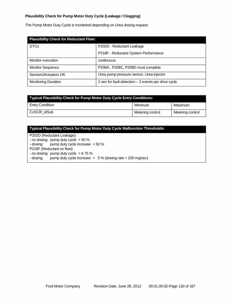
Ford Motor Company Revision Date: June 28, 2012 09.01.00.02-Page 130 of 167
Plausibility Check for Pump Motor Duty Cycle (Leakage / Clogging)
The Pump Motor Duty Cycle is monitored depending on Urea dosing request.
Plausibility Check for Reductant Flow:
DTCs P202D - Reductant Leakage
P218F - Reductant System Performance
Monitor execution continuous
Monitor Sequence P208A , P208C, P208D must complete
Sensors/Actuators OK Urea pump pressure sensor, Urea injector
Monitoring Duration 2 sec for fault detection – 3 events per drive cycle
Typical Plausibility Check for Pump Motor Duty Cycle Entry Conditions:
Entry Condition Minimum Maximum
CoSCR_stSub Metering control Metering control
Typical Plausibility Check for Pump Motor Duty Cycle Malfunction Thresholds:
P202D (Reductant Leakage): - no dosing: pump duty cycle > 50 % - dosing: pump duty cycle increase > 50 %
P218F (Reductant no flow):
- no dosing: pump duty cycle < 6.75 %
- dosing: pump duty cycle increase < 5 % (dosing rate > 200 mg/sec)
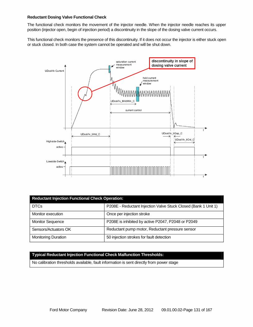
Ford Motor Company Revision Date: June 28, 2012 09.01.00.02-Page 131 of 167
Reductant Dosing Valve Functional Check
The functional check monitors the movement of the injector needle. When the injector needle reaches its upper
position (injector open, begin of injection period) a discontinuity in the slope of the dosing valve current occurs.
This functional check monitors the presence of this discontinuity. If it does not occur the injector is either stuck open
or stuck closed. In both case the system cannot be operated and will be shut down.
Reductant Injection Functional Check Operation:
DTCs P208E - Reductant Injection Valve Stuck Closed (Bank 1 Unit 1)
Monitor execution Once per injection stroke
Monitor Sequence P208E is inhibited by active P2047, P2048 or P2049
Sensors/Actuators OK Reductant pump motor, Reductant pressure sensor
Monitoring Duration 50 injection strokes for fault detection
Typical Reductant Injection Functional Check Malfunction Thresholds:
No calibration thresholds available, fault information is sent directly from power stage
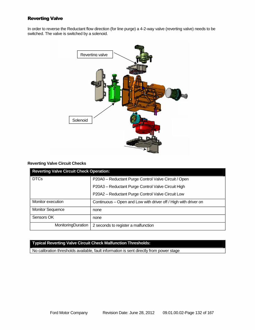
Ford Motor Company Revision Date: June 28, 2012 09.01.00.02-Page 132 of 167
Reverting Valve
In order to reverse the Reductant flow direction (for line purge) a 4-2-way valve (reverting valve) needs to be switched. The valve is switched by a solenoid.
Reverting Valve Circuit Checks
Reverting Valve Circuit Check Operation:
DTCs P20A0 – Reductant Purge Control Valve Circuit / Open
P20A3 – Reductant Purge Control Valve Circuit High
P20A2 – Reductant Purge Control Valve Circuit Low
Monitor execution Continuous – Open and Low with driver off / High with driver on
Monitor Sequence none
Sensors OK none
MonitoringDuration 2 seconds to register a malfunction
Typical Reverting Valve Circuit Check Malfunction Thresholds:
No calibration thresholds available, fault information is sent directly from power stage
Reverting valve
Solenoid
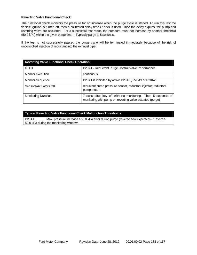
Ford Motor Company Revision Date: June 28, 2012 09.01.00.02-Page 133 of 167
Reverting Valve Functional Check
The functional check monitors the pressure for no increase when the purge cycle is started. To run this test the
vehicle ignition is turned off, then a calibrated delay time (7 sec) is used. Once the delay expires, the pump and
reverting valve are accuated. For a successful test result, the pressure must not increase by another threshold
(50.0 kPa) within the given purge time – Typically purge is 5 seconds.
If the test is not successfully passed the purge cycle will be terminated immediately because of the risk of
uncontrolled injection of reductant into the exhaust pipe.
Reverting Valve Functional Check Operation:
DTCs P20A1 - Reductant Purge Control Valve Performance
Monitor execution continuous
Monitor Sequence P20A1 is inhibited by active P20A0 , P20A3 or P20A2
Sensors/Actuators OK reductant pump pressure sensor, reductant injector, reductant pump motor
Monitoring Duration 7 secs after key off with no monitoring. Then 5 seconds of
monitoring with pump on reverting valve actuated (purge)
Typical Reverting Valve Functional Check Malfunction Thresholds:
P20A1 Max. pressure increase >50.0 kPa error during purge (reverse flow expected) - 1 event > 50.0 kPa during the monitoring window.
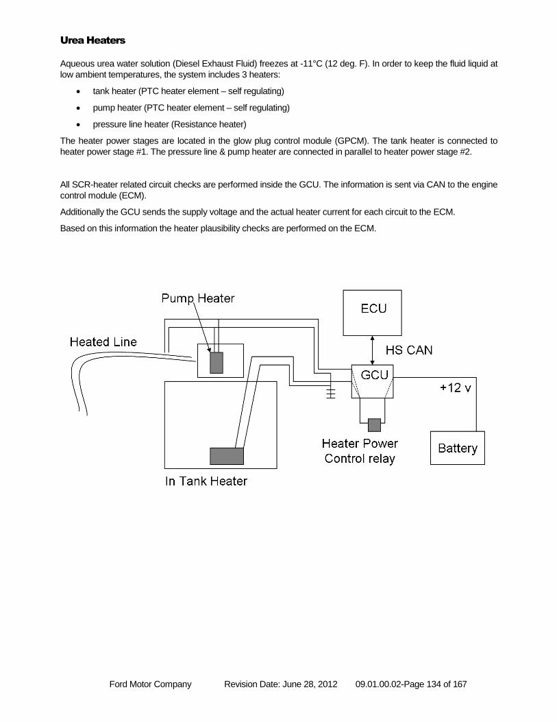
Ford Motor Company Revision Date: June 28, 2012 09.01.00.02-Page 134 of 167
Urea Heaters
Aqueous urea water solution (Diesel Exhaust Fluid) freezes at -11°C (12 deg. F). In order to keep the fluid liquid at
low ambient temperatures, the system includes 3 heaters:
tank heater (PTC heater element – self regulating)
pump heater (PTC heater element – self regulating)
pressure line heater (Resistance heater)
The heater power stages are located in the glow plug control module (GPCM). The tank heater is connected to
heater power stage #1. The pressure line & pump heater are connected in parallel to heater power stage #2.
All SCR-heater related circuit checks are performed inside the GCU. The information is sent via CAN to the engine
control module (ECM).
Additionally the GCU sends the supply voltage and the actual heater current for each circuit to the ECM.
Based on this information the heater plausibility checks are performed on the ECM.
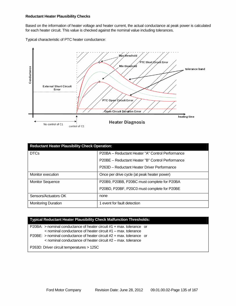
Ford Motor Company Revision Date: June 28, 2012 09.01.00.02-Page 135 of 167
Reductant Heater Plausibility Checks
Based on the information of heater voltage and heater current, the actual conductance at peak power is calculated
for each heater circuit. This value is checked against the nominal value including tolerances.
Typical characteristic of PTC heater conductance:
Reductant Heater Plausibility Check Operation:
DTCs P20BA – Reductant Heater "A" Control Performance
P20BE – Reductant Heater "B" Control Performance
P263D – Reductant Heater Driver Performance
Monitor execution Once per drive cycle (at peak heater power)
Monitor Sequence P20B9, P20BB, P20BC must complete for P20BA
P20BD, P20BF, P20C0 must complete for P20BE
Sensors/Actuators OK none
Monitoring Duration 1 event for fault detection
Typical Reductant Heater Plausibility Check Malfunction Thresholds:
P20BA: > nominal conductance of heater circuit #1 + max. tolerance or < nominal conductance of heater circuit #1 – max. tolerance
P20BE: > nominal conductance of heater circuit #2 + max. tolerance or
< nominal conductance of heater circuit #2 – max. tolerance
P263D: Driver circuit temperatures > 125C
Ford Motor Company Revision Date: June 28, 2012 09.01.00.02-Page 136 of 167
Additional plausibility check for heater circuit #2:
Pump heater & pressure line heater are connected in parallel to heater power stage #2. In order to be able to
detect a failure of just one of both heaters, the conductance of heater circuit #2 is continuously checked against a
minimum threshold. E.g. if the pressure line heater gets disconnected after peak conductance occurred, neither the
plausibility check nor the circuit checks inside the GCU can detect this error. Therefore this continuous check
becomes necessary.
Reductant Heater Plausibility Check Operation (Heater Circuit #2):
DTCs P20BE – Reductant Heater "B" Control Performance
Monitor execution Continuously, if heater “B” is activated
Monitor Sequence P20BD, P20BF, P20C0 must complete for P20BE
Sensors/Actuators OK Pressure line heater
Monitoring Duration 2200 ms for fault detection
Typical Reductant Heater Plausibility Check Malfunction Thresholds (Heater Circuit #2):
P20BE: conductance of heater circuit #2 < 0.3 Ω-1
Reductant tank heater performance check (heater circuit #1):
The tank heater is located in close proximity to the tank temperature sensor. Therefore the tank temperature
sensor can be used to monitor the tank heater performance.
When the tank heater is activated, the tank temperature is expected to rise. If this is not the case a fault will be set.
If the vehicle is operated for several consecutive short drive cycles, the test may require more than one drive cycle
to complete.
Reductant Heater Performance Check Operation (Heater Circuit #1):
DTCs P209F – Reductant Tank Heater Control Performance
Monitor execution Once per heat cycle (after cold start)
Monitor Sequence P20B9, P20BB, P20BC must complete for P209F
Sensors/Actuators OK tank temperature sensor, tank heater
Monitoring Duration 2200 ms for fault detection
Typical Reductant Heater Performance Check Malfunction Thresholds (Heater Circuit #1):
P209F: temperature increase < 0.5°C
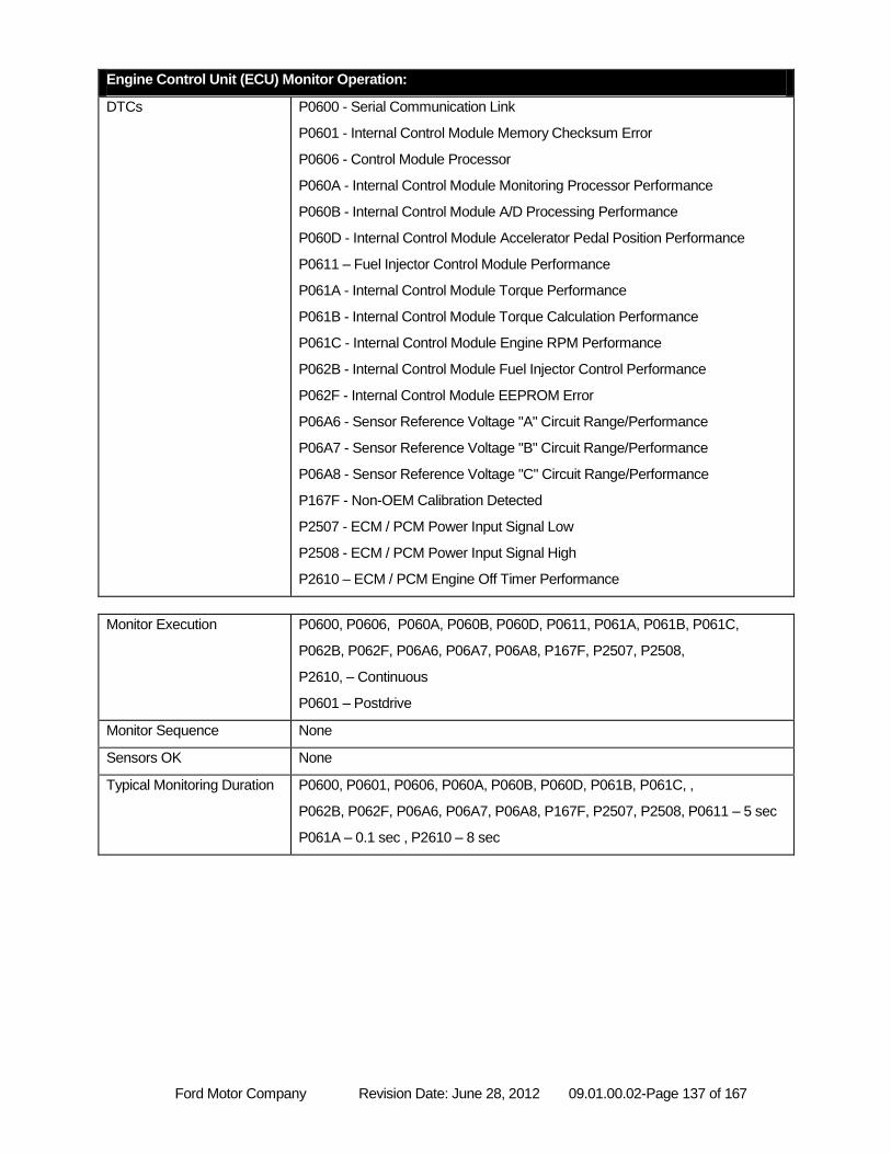
Ford Motor Company Revision Date: June 28, 2012 09.01.00.02-Page 137 of 167
Engine Control Unit (ECU) Monitor Operation:
DTCs P0600 - Serial Communication Link
P0601 - Internal Control Module Memory Checksum Error
P0606 - Control Module Processor
P060A - Internal Control Module Monitoring Processor Performance
P060B - Internal Control Module A/D Processing Performance
P060D - Internal Control Module Accelerator Pedal Position Performance
P0611 – Fuel Injector Control Module Performance
P061A - Internal Control Module Torque Performance
P061B - Internal Control Module Torque Calculation Performance
P061C - Internal Control Module Engine RPM Performance
P062B - Internal Control Module Fuel Injector Control Performance
P062F - Internal Control Module EEPROM Error
P06A6 - Sensor Reference Voltage "A" Circuit Range/Performance
P06A7 - Sensor Reference Voltage "B" Circuit Range/Performance
P06A8 - Sensor Reference Voltage "C" Circuit Range/Performance
P167F - Non-OEM Calibration Detected
P2507 - ECM / PCM Power Input Signal Low
P2508 - ECM / PCM Power Input Signal High
P2610 – ECM / PCM Engine Off Timer Performance
Monitor Execution P0600, P0606, P060A, P060B, P060D, P0611, P061A, P061B, P061C,
P062B, P062F, P06A6, P06A7, P06A8, P167F, P2507, P2508,
P2610, – Continuous
P0601 – Postdrive
Monitor Sequence None
Sensors OK None
Typical Monitoring Duration P0600, P0601, P0606, P060A, P060B, P060D, P061B, P061C, ,
P062B, P062F, P06A6, P06A7, P06A8, P167F, P2507, P2508, P0611 – 5 sec
P061A – 0.1 sec , P2610 – 8 sec
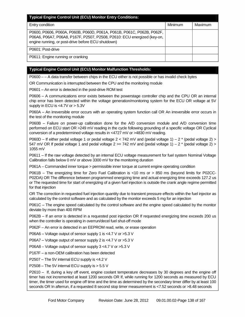
Ford Motor Company Revision Date: June 28, 2012 09.01.00.02-Page 138 of 167
Typical Engine Control Unit (ECU) Monitor Entry Conditions:
Entry condition Minimum Maximum
P0600, P0606, P060A, P060B, P060D, P061A, P061B, P061C, P062B, P062F,
P06A6, P06A7, P06A8, P167F, P2507, P2508, P2610: ECU energized (key-on,
engine running, or post-drive before ECU shutdown)
P0601: Post-drive
P0611: Engine running or cranking
Typical Engine Control Unit (ECU) Monitor Malfunction Thresholds:
P0600 – – A data transfer between chips in the ECU either is not possible or has invalid check bytes
OR Communication is interrupted between the CPU and the monitoring module
P0601 – An error is detected in the post-drive ROM test
P0606 – A communications error exists between the powerstage controller chip and the CPU OR an internal
chip error has been detected within the voltage generation/monitoring system for the ECU OR voltage at 5V
supply in ECU is <4.7V or > 5.3V
P060A – An irreversible error occurs with an operating system function call OR An irreversible error occurs in
the test of the monitoring module
P060B – Failure on power-up calibration done for the A/D conversion module and A/D conversion time
performed on ECU start OR >249 mV reading in the cycle following grounding of a specific voltage OR Cyclical
conversion of a predetermined voltage results in <4727 mV or >4830 mV reading.
P060D – If either pedal voltage 1 or pedal voltage 2 < 742 mV and (pedal voltage 1) – 2 * (pedal voltage 2) >
547 mV OR If pedal voltage 1 and pedal voltage 2 >= 742 mV and (pedal voltage 1) – 2 * (pedal voltage 2) >
1055 mV
P0611 – If the raw voltage detected by an internal ECU voltage measurement for fuel system Nominal Voltage
Calibration falls below 0 mV or above 3300 mV for the monitoring duration
P061A – Commanded inner torque > permissible inner torque at current engine operating condition
P061B – The energizing time for Zero Fuel Calibration is <10 ms or > 850 ms (beyond limits for P02CC-
P02DA) OR The difference between programmed energizing time and actual energizing time exceeds 127.2 us
or The requested time for start of energizing of a given fuel injection is outside the crank angle regime permitted
for that injection
OR The correction in requested fuel injection quantity due to transient pressure effects within the fuel injector as
calculated by the control software and as calculated by the monitor exceeds 5 mg for an injection
P061C – The engine speed calculated by the control software and the engine speed calculated by the monitor
deviate by more than 400 RPM
P062B – If an error is detected in a requested post injection OR If requested energizing time exceeds 200 us
when the controller is operating in overrun/decel fuel shut-off mode
P062F – An error is detected in an EEPROM read, write, or erase operation
P06A6 – Voltage output of sensor supply 1 is <4.7 V or >5.3 V
P06A7 – Voltage output of sensor supply 2 is <4.7 V or >5.3 V
P06A8 – Voltage output of sensor supply 3 <4.7 V or >5.3 V
P167F – a non-OEM calibration has been detected
P2507 – The 5V internal ECU supply is <4.2 V
P2508 – The 5V internal ECU supply is > 5.5 V
P2610 – If, during a key off event, engine coolant temperature decreases by 30 degrees and the engine off
timer has not incremented at least 1200 seconds OR If, while running for 1200 seconds as measured by ECU
timer, the timer used for engine off time and the time as determined by the secondary timer differ by at least 100
seconds OR In afterrun, if a requested 8 second stop timer measurement is <7.52 seconds or >8.48 seconds
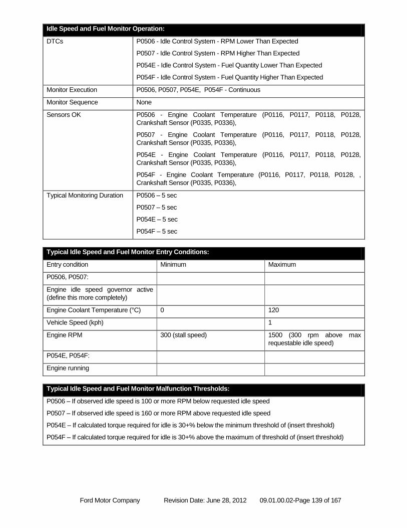
Ford Motor Company Revision Date: June 28, 2012 09.01.00.02-Page 139 of 167
Idle Speed and Fuel Monitor Operation:
DTCs P0506 - Idle Control System - RPM Lower Than Expected
P0507 - Idle Control System - RPM Higher Than Expected
P054E - Idle Control System - Fuel Quantity Lower Than Expected
P054F - Idle Control System - Fuel Quantity Higher Than Expected
Monitor Execution P0506, P0507, P054E, P054F - Continuous
Monitor Sequence None
Sensors OK P0506 - Engine Coolant Temperature (P0116, P0117, P0118, P0128,
Crankshaft Sensor (P0335, P0336),
P0507 - Engine Coolant Temperature (P0116, P0117, P0118, P0128,
Crankshaft Sensor (P0335, P0336),
P054E - Engine Coolant Temperature (P0116, P0117, P0118, P0128,
Crankshaft Sensor (P0335, P0336),
P054F - Engine Coolant Temperature (P0116, P0117, P0118, P0128, ,
Crankshaft Sensor (P0335, P0336),
Typical Monitoring Duration P0506 – 5 sec
P0507 – 5 sec
P054E – 5 sec
P054F – 5 sec
Typical Idle Speed and Fuel Monitor Entry Conditions:
Entry condition Minimum Maximum
P0506, P0507:
Engine idle speed governor active
(define this more completely)
Engine Coolant Temperature (°C) 0 120
Vehicle Speed (kph) 1
Engine RPM 300 (stall speed) 1500 (300 rpm above max
requestable idle speed)
P054E, P054F:
Engine running
Typical Idle Speed and Fuel Monitor Malfunction Thresholds:
P0506 – If observed idle speed is 100 or more RPM below requested idle speed
P0507 – If observed idle speed is 160 or more RPM above requested idle speed
P054E – If calculated torque required for idle is 30+% below the minimum threshold of (insert threshold)
P054F – If calculated torque required for idle is 30+% above the maximum of threshold of (insert threshold)
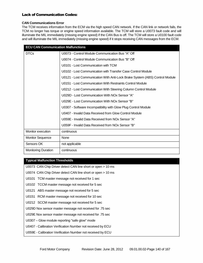
Ford Motor Company Revision Date: June 28, 2012 09.01.00.02-Page 140 of 167
Lack of Communication Codes:
CAN Communications Error
The TCM receives information from the ECM via the high speed CAN network. If the CAN link or network fails, the
TCM no longer has torque or engine speed information available. The TCM will store a U0073 fault code and will
illuminate the MIL immediately (missing engine speed) if the CAN Bus is off. The TCM will store a U0100 fault code
and will illuminate the MIL immediately (missing engine speed) if it stops receiving CAN messages from the ECM.
ECU CAN Communication Malfunctions
DTCs U0073 - Control Module Communication Bus "A" Off
U0074 - Control Module Communication Bus "B" Off
U0101 - Lost Communication with TCM
U0102 - Lost Communication with Transfer Case Control Module
U0121 - Lost Communication With Anti-Lock Brake System (ABS) Control Module
U0151 - Lost Communication With Restraints Control Module
U0212 - Lost Communication With Steering Column Control Module
U029D - Lost Communication With NOx Sensor "A"
U029E - Lost Communication With NOx Sensor "B"
U0307 - Software Incompatibility with Glow Plug Control Module
U0407 - Invalid Data Received from Glow Control Module
U059E - Invalid Data Received from NOx Sensor "A"
U059F - Invalid Data Received from NOx Sensor "B"
Monitor execution continuous
Monitor Sequence None
Sensors OK not applicable
Monitoring Duration continuous
Typical Malfunction Thresholds
U0073 CAN Chip Driver detect CAN line short or open > 10 ms
U0074 CAN Chip Driver detect CAN line short or open > 10 ms
U0101 TCM master message not received for 1 sec
U0102 TCCM master message not received for 5 sec
U0121 ABS master message not received for 5 sec
U0151 RCM master message not received for 10 sec
U0212 SCCM master message not received for 5 sec
U029D Nox sensor master message not received for .75 sec
U029E Nox sensor master message not received for .75 sec
U0307 – Glow module reporting "safe glow" mode
U0407 - Calibration Verification Number not received by ECU
U059E - Calibration Verification Number not received by ECU
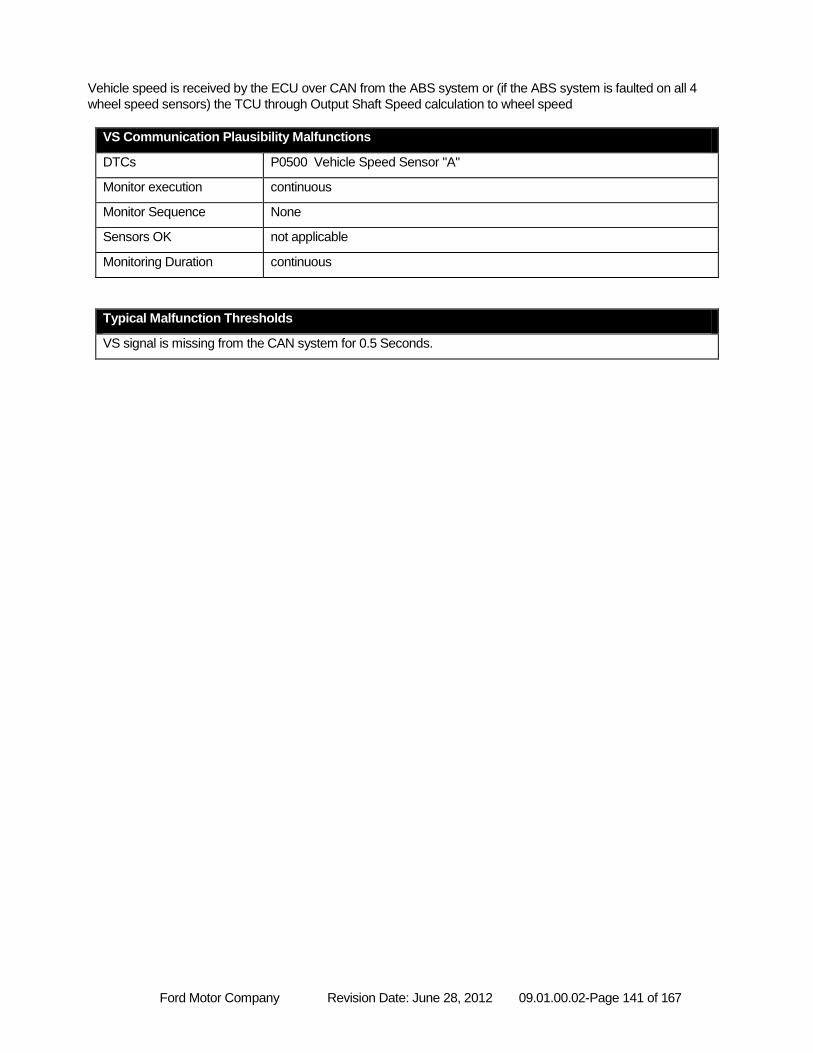
Ford Motor Company Revision Date: June 28, 2012 09.01.00.02-Page 141 of 167
Vehicle speed is received by the ECU over CAN from the ABS system or (if the ABS system is faulted on all 4
wheel speed sensors) the TCU through Output Shaft Speed calculation to wheel speed
VS Communication Plausibility Malfunctions
DTCs P0500 Vehicle Speed Sensor "A"
Monitor execution continuous
Monitor Sequence None
Sensors OK not applicable
Monitoring Duration continuous
Typical Malfunction Thresholds
VS signal is missing from the CAN system for 0.5 Seconds.
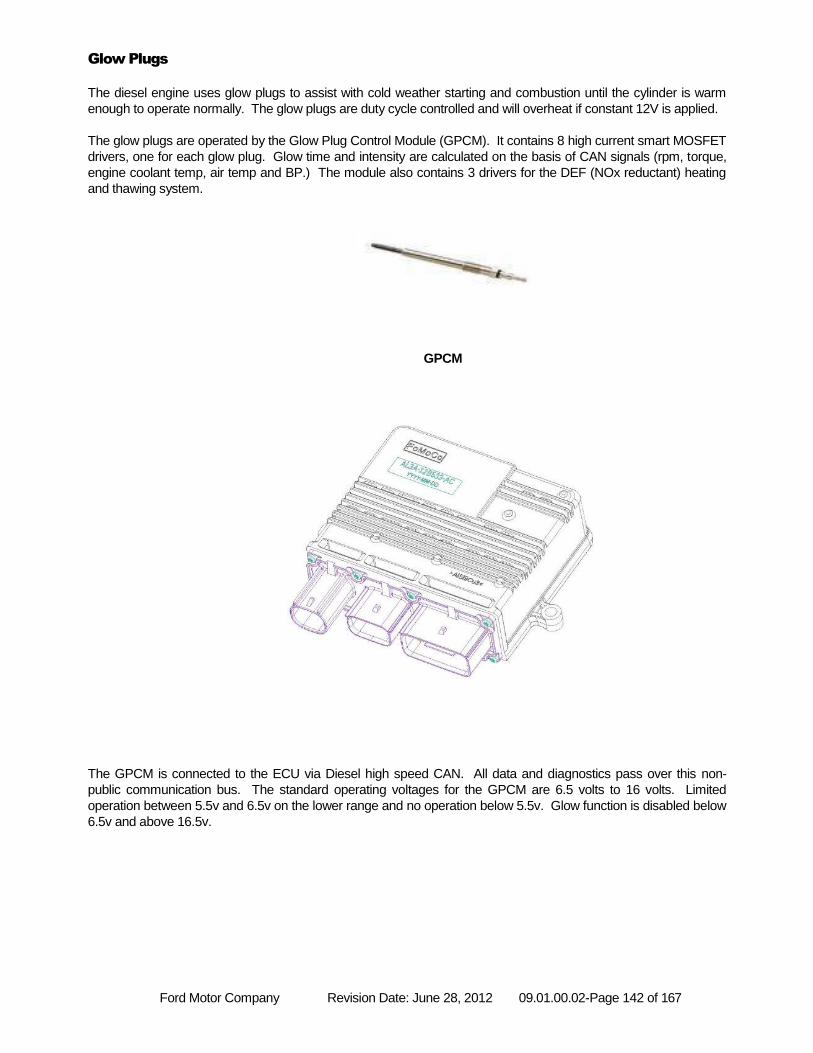
Ford Motor Company Revision Date: June 28, 2012 09.01.00.02-Page 142 of 167
Glow Plugs
The diesel engine uses glow plugs to assist with cold weather starting and combustion until the cylinder is warm
enough to operate normally. The glow plugs are duty cycle controlled and will overheat if constant 12V is applied.
The glow plugs are operated by the Glow Plug Control Module (GPCM). It contains 8 high current smart MOSFET
drivers, one for each glow plug. Glow time and intensity are calculated on the basis of CAN signals (rpm, torque,
engine coolant temp, air temp and BP.) The module also contains 3 drivers for the DEF (NOx reductant) heating
and thawing system.
GPCM
The GPCM is connected to the ECU via Diesel high speed CAN. All data and diagnostics pass over this non-
public communication bus. The standard operating voltages for the GPCM are 6.5 volts to 16 volts. Limited
operation between 5.5v and 6.5v on the lower range and no operation below 5.5v. Glow function is disabled below
6.5v and above 16.5v.
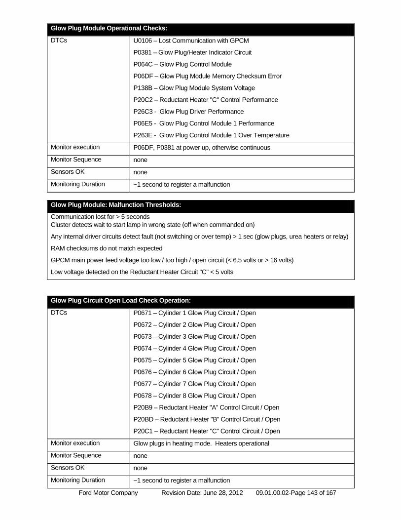
Ford Motor Company Revision Date: June 28, 2012 09.01.00.02-Page 143 of 167
Glow Plug Module Operational Checks:
DTCs U0106 – Lost Communication with GPCM
P0381 – Glow Plug/Heater Indicator Circuit
P064C – Glow Plug Control Module
P06DF – Glow Plug Module Memory Checksum Error
P138B – Glow Plug Module System Voltage
P20C2 – Reductant Heater "C" Control Performance
P26C3 - Glow Plug Driver Performance
P06E5 - Glow Plug Control Module 1 Performance
P263E - Glow Plug Control Module 1 Over Temperature
Monitor execution P06DF, P0381 at power up, otherwise continuous
Monitor Sequence none
Sensors OK none
Monitoring Duration ~1 second to register a malfunction
Glow Plug Module: Malfunction Thresholds:
Communication lost for > 5 seconds
Cluster detects wait to start lamp in wrong state (off when commanded on)
Any internal driver circuits detect fault (not switching or over temp) > 1 sec (glow plugs, urea heaters or relay)
RAM checksums do not match expected
GPCM main power feed voltage too low / too high / open circuit (< 6.5 volts or > 16 volts)
Low voltage detected on the Reductant Heater Circuit "C" < 5 volts
Glow Plug Circuit Open Load Check Operation:
DTCs P0671 – Cylinder 1 Glow Plug Circuit / Open
P0672 – Cylinder 2 Glow Plug Circuit / Open
P0673 – Cylinder 3 Glow Plug Circuit / Open
P0674 – Cylinder 4 Glow Plug Circuit / Open
P0675 – Cylinder 5 Glow Plug Circuit / Open
P0676 – Cylinder 6 Glow Plug Circuit / Open
P0677 – Cylinder 7 Glow Plug Circuit / Open
P0678 – Cylinder 8 Glow Plug Circuit / Open
P20B9 – Reductant Heater "A" Control Circuit / Open
P20BD – Reductant Heater "B" Control Circuit / Open
P20C1 – Reductant Heater "C" Control Circuit / Open
Monitor execution Glow plugs in heating mode. Heaters operational
Monitor Sequence none
Sensors OK none
Monitoring Duration ~1 second to register a malfunction
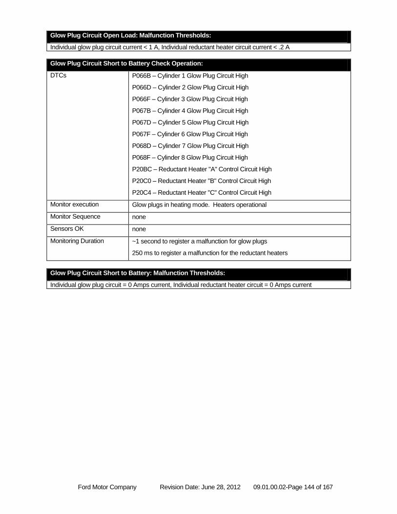
Ford Motor Company Revision Date: June 28, 2012 09.01.00.02-Page 144 of 167
Glow Plug Circuit Open Load: Malfunction Thresholds:
Individual glow plug circuit current < 1 A, Individual reductant heater circuit current < .2 A
Glow Plug Circuit Short to Battery Check Operation:
DTCs P066B – Cylinder 1 Glow Plug Circuit High
P066D – Cylinder 2 Glow Plug Circuit High
P066F – Cylinder 3 Glow Plug Circuit High
P067B – Cylinder 4 Glow Plug Circuit High
P067D – Cylinder 5 Glow Plug Circuit High
P067F – Cylinder 6 Glow Plug Circuit High
P068D – Cylinder 7 Glow Plug Circuit High
P068F – Cylinder 8 Glow Plug Circuit High
P20BC – Reductant Heater "A" Control Circuit High
P20C0 – Reductant Heater "B" Control Circuit High
P20C4 – Reductant Heater "C" Control Circuit High
Monitor execution Glow plugs in heating mode. Heaters operational
Monitor Sequence none
Sensors OK none
Monitoring Duration ~1 second to register a malfunction for glow plugs
250 ms to register a malfunction for the reductant heaters
Glow Plug Circuit Short to Battery: Malfunction Thresholds:
Individual glow plug circuit = 0 Amps current, Individual reductant heater circuit = 0 Amps current
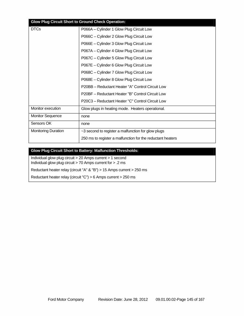
Ford Motor Company Revision Date: June 28, 2012 09.01.00.02-Page 145 of 167
Glow Plug Circuit Short to Ground Check Operation:
DTCs P066A – Cylinder 1 Glow Plug Circuit Low
P066C – Cylinder 2 Glow Plug Circuit Low
P066E – Cylinder 3 Glow Plug Circuit Low
P067A – Cylinder 4 Glow Plug Circuit Low
P067C – Cylinder 5 Glow Plug Circuit Low
P067E – Cylinder 6 Glow Plug Circuit Low
P068C – Cylinder 7 Glow Plug Circuit Low
P068E – Cylinder 8 Glow Plug Circuit Low
P20BB – Reductant Heater "A" Control Circuit Low
P20BF – Reductant Heater "B" Control Circuit Low
P20C3 – Reductant Heater "C" Control Circuit Low
Monitor execution Glow plugs in heating mode. Heaters operational.
Monitor Sequence none
Sensors OK none
Monitoring Duration ~3 second to register a malfunction for glow plugs
250 ms to register a malfunction for the reductant heaters
Glow Plug Circuit Short to Battery: Malfunction Thresholds:
Individual glow plug circuit > 20 Amps current > 1 second
Individual glow plug circuit > 70 Amps current for > .2 ms
Reductant heater relay (circuit "A" & "B") > 15 Amps current > 250 ms
Reductant heater relay (circuit "C") > 6 Amps current > 250 ms
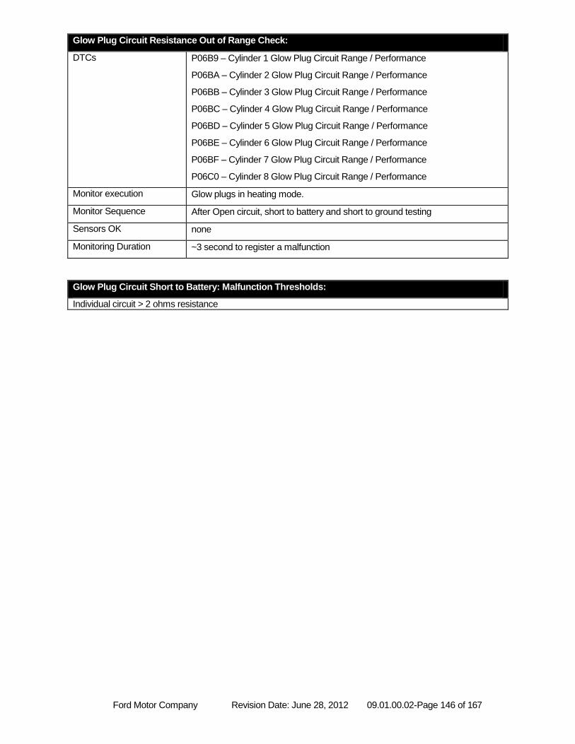
Ford Motor Company Revision Date: June 28, 2012 09.01.00.02-Page 146 of 167
Glow Plug Circuit Resistance Out of Range Check:
DTCs P06B9 – Cylinder 1 Glow Plug Circuit Range / Performance
P06BA – Cylinder 2 Glow Plug Circuit Range / Performance
P06BB – Cylinder 3 Glow Plug Circuit Range / Performance
P06BC – Cylinder 4 Glow Plug Circuit Range / Performance
P06BD – Cylinder 5 Glow Plug Circuit Range / Performance
P06BE – Cylinder 6 Glow Plug Circuit Range / Performance
P06BF – Cylinder 7 Glow Plug Circuit Range / Performance
P06C0 – Cylinder 8 Glow Plug Circuit Range / Performance
Monitor execution Glow plugs in heating mode.
Monitor Sequence After Open circuit, short to battery and short to ground testing
Sensors OK none
Monitoring Duration ~3 second to register a malfunction
Glow Plug Circuit Short to Battery: Malfunction Thresholds:
Individual circuit > 2 ohms resistance
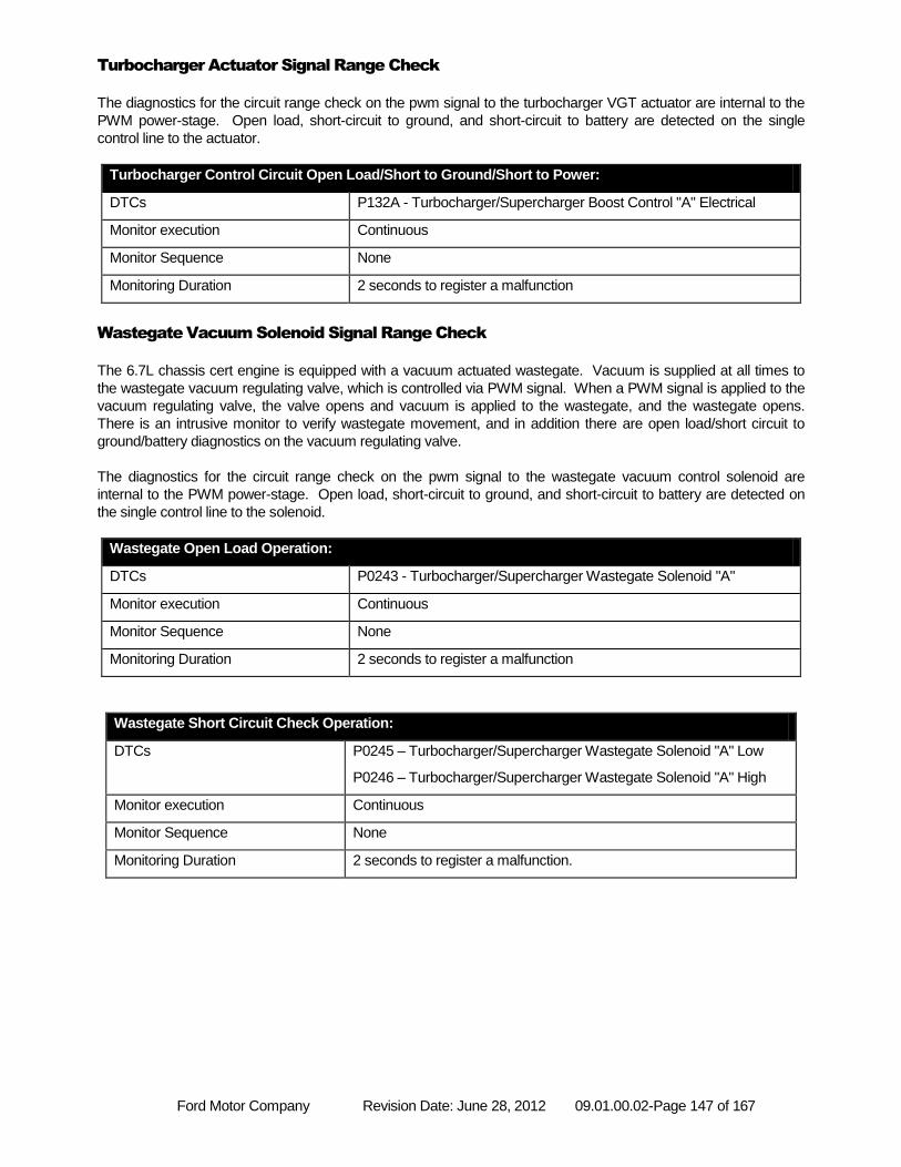
Ford Motor Company Revision Date: June 28, 2012 09.01.00.02-Page 147 of 167
Turbocharger Actuator Signal Range Check
The diagnostics for the circuit range check on the pwm signal to the turbocharger VGT actuator are internal to the
PWM power-stage. Open load, short-circuit to ground, and short-circuit to battery are detected on the single
control line to the actuator.
Turbocharger Control Circuit Open Load/Short to Ground/Short to Power:
DTCs P132A - Turbocharger/Supercharger Boost Control "A" Electrical
Monitor execution Continuous
Monitor Sequence None
Monitoring Duration 2 seconds to register a malfunction
Wastegate Vacuum Solenoid Signal Range Check
The 6.7L chassis cert engine is equipped with a vacuum actuated wastegate. Vacuum is supplied at all times to
the wastegate vacuum regulating valve, which is controlled via PWM signal. When a PWM signal is applied to the
vacuum regulating valve, the valve opens and vacuum is applied to the wastegate, and the wastegate opens.
There is an intrusive monitor to verify wastegate movement, and in addition there are open load/short circuit to
ground/battery diagnostics on the vacuum regulating valve.
The diagnostics for the circuit range check on the pwm signal to the wastegate vacuum control solenoid are
internal to the PWM power-stage. Open load, short-circuit to ground, and short-circuit to battery are detected on
the single control line to the solenoid.
Wastegate Open Load Operation:
DTCs P0243 - Turbocharger/Supercharger Wastegate Solenoid "A"
Monitor execution Continuous
Monitor Sequence None
Monitoring Duration 2 seconds to register a malfunction
Wastegate Short Circuit Check Operation:
DTCs P0245 – Turbocharger/Supercharger Wastegate Solenoid "A" Low
P0246 – Turbocharger/Supercharger Wastegate Solenoid "A" High
Monitor execution Continuous
Monitor Sequence None
Monitoring Duration 2 seconds to register a malfunction.
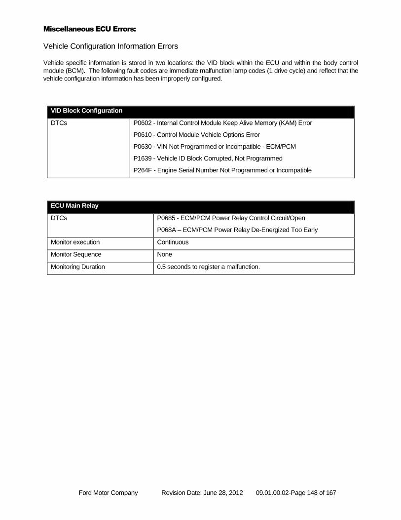
Ford Motor Company Revision Date: June 28, 2012 09.01.00.02-Page 148 of 167
Miscellaneous ECU Errors:
Vehicle Configuration Information Errors
Vehicle specific information is stored in two locations: the VID block within the ECU and within the body control
module (BCM). The following fault codes are immediate malfunction lamp codes (1 drive cycle) and reflect that the
vehicle configuration information has been improperly configured.
VID Block Configuration
DTCs P0602 - Internal Control Module Keep Alive Memory (KAM) Error
P0610 - Control Module Vehicle Options Error
P0630 - VIN Not Programmed or Incompatible - ECM/PCM
P1639 - Vehicle ID Block Corrupted, Not Programmed
P264F - Engine Serial Number Not Programmed or Incompatible
ECU Main Relay
DTCs P0685 - ECM/PCM Power Relay Control Circuit/Open
P068A – ECM/PCM Power Relay De-Energized Too Early
Monitor execution Continuous
Monitor Sequence None
Monitoring Duration 0.5 seconds to register a malfunction.
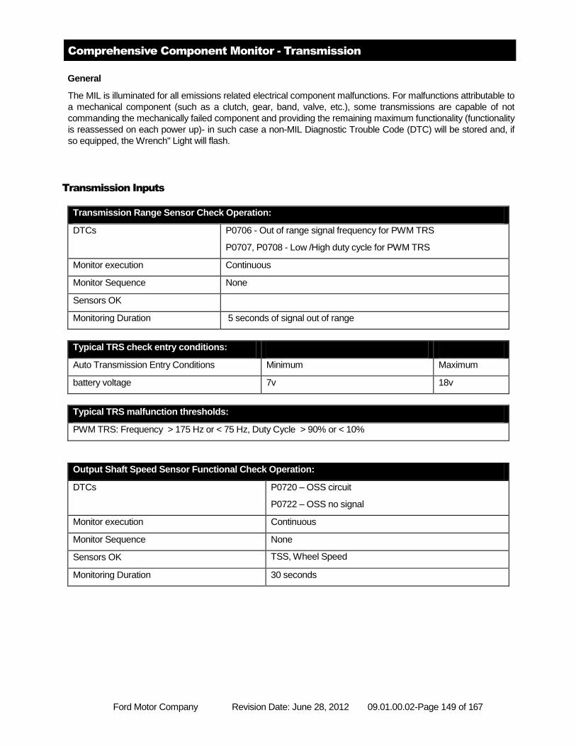
Ford Motor Company Revision Date: June 28, 2012 09.01.00.02-Page 149 of 167
Comprehensive Component Monitor - Transmission
General
The MIL is illuminated for all emissions related electrical component malfunctions. For malfunctions attributable to
a mechanical component (such as a clutch, gear, band, valve, etc.), some transmissions are capable of not
commanding the mechanically failed component and providing the remaining maximum functionality (functionality
is reassessed on each power up)- in such case a non-MIL Diagnostic Trouble Code (DTC) will be stored and, if
so equipped, the Wrench" Light will flash.
Transmission Inputs
Transmission Range Sensor Check Operation:
DTCs P0706 - Out of range signal frequency for PWM TRS
P0707, P0708 - Low /High duty cycle for PWM TRS
Monitor execution Continuous
Monitor Sequence None
Sensors OK
Monitoring Duration 5 seconds of signal out of range
Typical TRS check entry conditions:
Auto Transmission Entry Conditions Minimum Maximum
battery voltage 7v 18v
Typical TRS malfunction thresholds:
PWM TRS: Frequency > 175 Hz or < 75 Hz, Duty Cycle > 90% or < 10%
Output Shaft Speed Sensor Functional Check Operation:
DTCs P0720 – OSS circuit
P0722 – OSS no signal
Monitor execution Continuous
Monitor Sequence None
Sensors OK TSS, Wheel Speed
Monitoring Duration 30 seconds
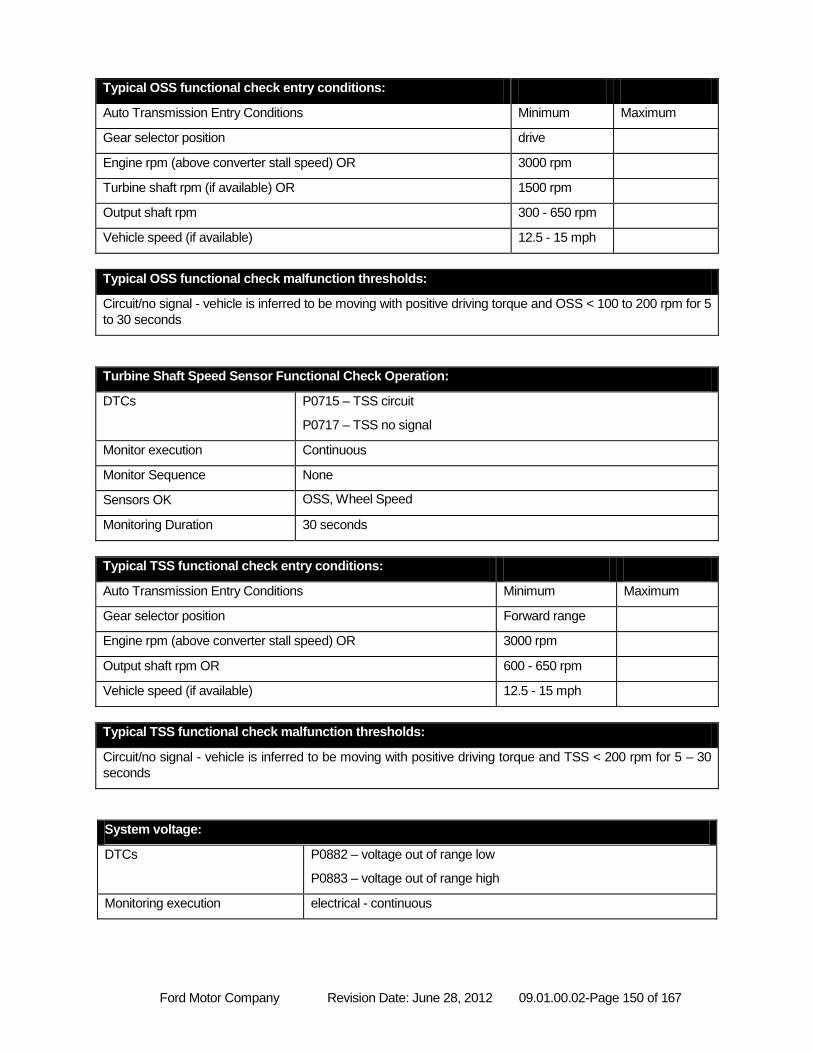
Ford Motor Company Revision Date: June 28, 2012 09.01.00.02-Page 150 of 167
Typical OSS functional check entry conditions:
Auto Transmission Entry Conditions Minimum Maximum
Gear selector position drive
Engine rpm (above converter stall speed) OR 3000 rpm
Turbine shaft rpm (if available) OR 1500 rpm
Output shaft rpm 300 - 650 rpm
Vehicle speed (if available) 12.5 - 15 mph
Typical OSS functional check malfunction thresholds:
Circuit/no signal - vehicle is inferred to be moving with positive driving torque and OSS < 100 to 200 rpm for 5
to 30 seconds
Turbine Shaft Speed Sensor Functional Check Operation:
DTCs P0715 – TSS circuit
P0717 – TSS no signal
Monitor execution Continuous
Monitor Sequence None
Sensors OK OSS, Wheel Speed
Monitoring Duration 30 seconds
Typical TSS functional check entry conditions:
Auto Transmission Entry Conditions Minimum Maximum
Gear selector position Forward range
Engine rpm (above converter stall speed) OR 3000 rpm
Output shaft rpm OR 600 - 650 rpm
Vehicle speed (if available) 12.5 - 15 mph
Typical TSS functional check malfunction thresholds:
Circuit/no signal - vehicle is inferred to be moving with positive driving torque and TSS < 200 rpm for 5 – 30
seconds
System voltage:
DTCs P0882 – voltage out of range low
P0883 – voltage out of range high
Monitoring execution electrical - continuous
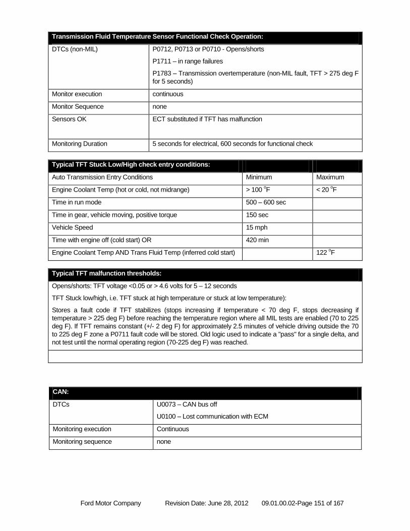
Ford Motor Company Revision Date: June 28, 2012 09.01.00.02-Page 151 of 167
Transmission Fluid Temperature Sensor Functional Check Operation:
DTCs (non-MIL) P0712, P0713 or P0710 - Opens/shorts
P1711 – in range failures
P1783 – Transmission overtemperature (non-MIL fault, TFT > 275 deg F
for 5 seconds)
Monitor execution continuous
Monitor Sequence none
Sensors OK ECT substituted if TFT has malfunction
Monitoring Duration 5 seconds for electrical, 600 seconds for functional check
Typical TFT Stuck Low/High check entry conditions:
Auto Transmission Entry Conditions Minimum Maximum
Engine Coolant Temp (hot or cold, not midrange) > 100 oF < 20
oF
Time in run mode 500 – 600 sec
Time in gear, vehicle moving, positive torque 150 sec
Vehicle Speed 15 mph
Time with engine off (cold start) OR 420 min
Engine Coolant Temp AND Trans Fluid Temp (inferred cold start) 122 oF
Typical TFT malfunction thresholds:
Opens/shorts: TFT voltage <0.05 or > 4.6 volts for 5 – 12 seconds
TFT Stuck low/high, i.e. TFT stuck at high temperature or stuck at low temperature):
Stores a fault code if TFT stabilizes (stops increasing if temperature < 70 deg F, stops decreasing if
temperature > 225 deg F) before reaching the temperature region where all MIL tests are enabled (70 to 225
deg F). If TFT remains constant (+/- 2 deg F) for approximately 2.5 minutes of vehicle driving outside the 70
to 225 deg F zone a P0711 fault code will be stored. Old logic used to indicate a "pass" for a single delta, and
not test until the normal operating region (70-225 deg F) was reached.
CAN:
DTCs U0073 – CAN bus off
U0100 – Lost communication with ECM
Monitoring execution Continuous
Monitoring sequence none
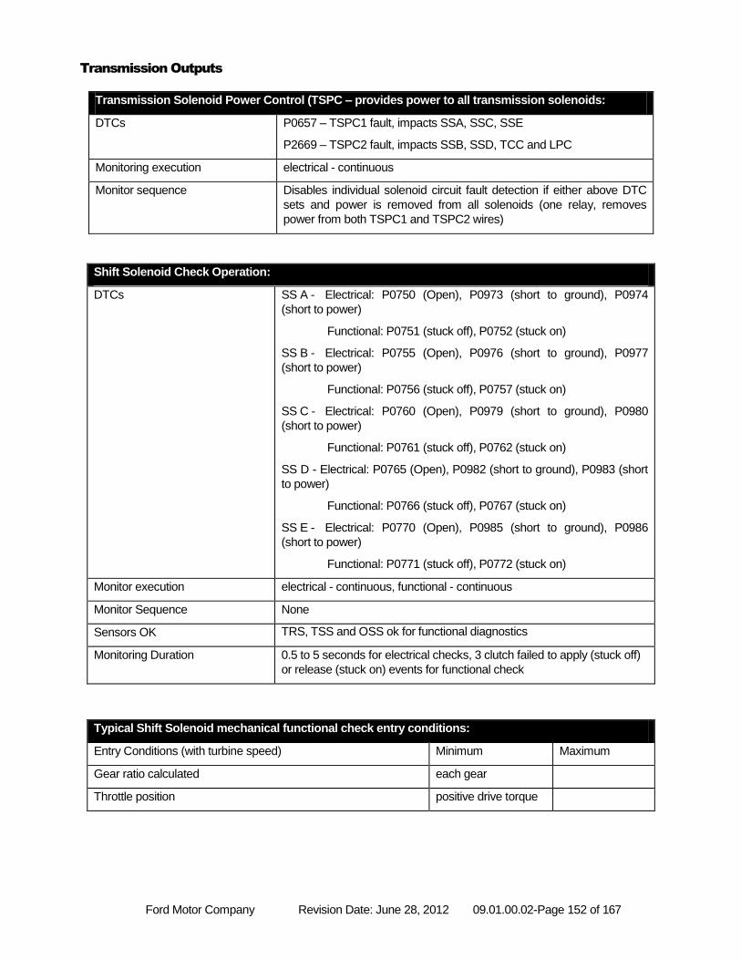
Ford Motor Company Revision Date: June 28, 2012 09.01.00.02-Page 152 of 167
Transmission Outputs
Transmission Solenoid Power Control (TSPC – provides power to all transmission solenoids:
DTCs P0657 – TSPC1 fault, impacts SSA, SSC, SSE
P2669 – TSPC2 fault, impacts SSB, SSD, TCC and LPC
Monitoring execution electrical - continuous
Monitor sequence Disables individual solenoid circuit fault detection if either above DTC
sets and power is removed from all solenoids (one relay, removes
power from both TSPC1 and TSPC2 wires)
Shift Solenoid Check Operation:
DTCs SS A - Electrical: P0750 (Open), P0973 (short to ground), P0974
(short to power)
Functional: P0751 (stuck off), P0752 (stuck on)
SS B - Electrical: P0755 (Open), P0976 (short to ground), P0977
(short to power)
Functional: P0756 (stuck off), P0757 (stuck on)
SS C - Electrical: P0760 (Open), P0979 (short to ground), P0980
(short to power)
Functional: P0761 (stuck off), P0762 (stuck on)
SS D - Electrical: P0765 (Open), P0982 (short to ground), P0983 (short
to power)
Functional: P0766 (stuck off), P0767 (stuck on)
SS E - Electrical: P0770 (Open), P0985 (short to ground), P0986
(short to power)
Functional: P0771 (stuck off), P0772 (stuck on)
Monitor execution electrical - continuous, functional - continuous
Monitor Sequence None
Sensors OK TRS, TSS and OSS ok for functional diagnostics
Monitoring Duration 0.5 to 5 seconds for electrical checks, 3 clutch failed to apply (stuck off)
or release (stuck on) events for functional check
Typical Shift Solenoid mechanical functional check entry conditions:
Entry Conditions (with turbine speed) Minimum Maximum
Gear ratio calculated each gear
Throttle position positive drive torque
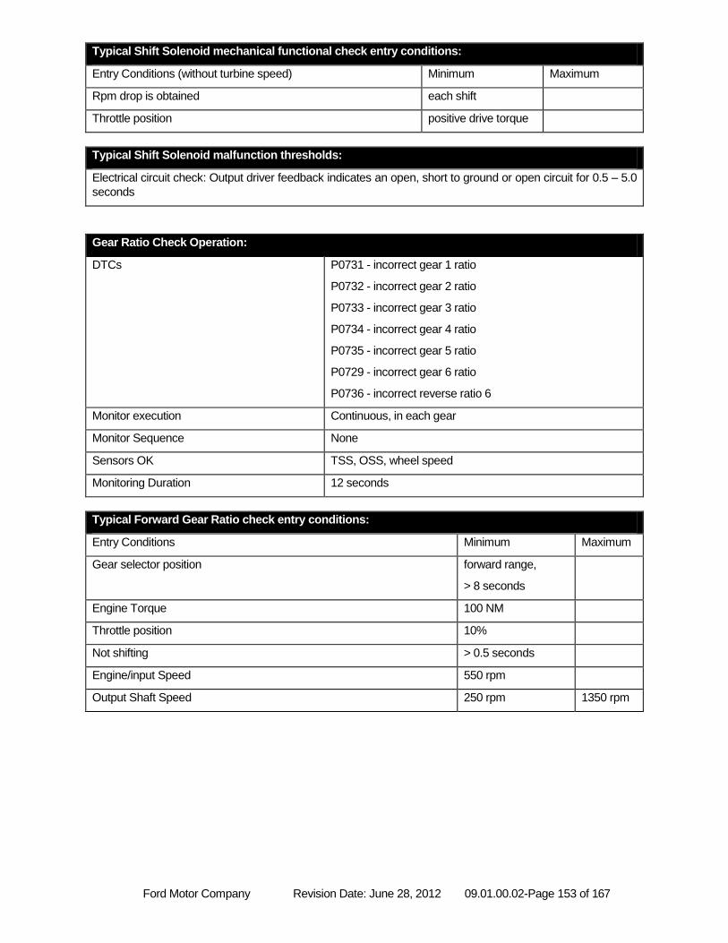
Ford Motor Company Revision Date: June 28, 2012 09.01.00.02-Page 153 of 167
Typical Shift Solenoid mechanical functional check entry conditions:
Entry Conditions (without turbine speed) Minimum Maximum
Rpm drop is obtained each shift
Throttle position positive drive torque
Typical Shift Solenoid malfunction thresholds:
Electrical circuit check: Output driver feedback indicates an open, short to ground or open circuit for 0.5 – 5.0
seconds
Gear Ratio Check Operation:
DTCs P0731 - incorrect gear 1 ratio
P0732 - incorrect gear 2 ratio
P0733 - incorrect gear 3 ratio
P0734 - incorrect gear 4 ratio
P0735 - incorrect gear 5 ratio
P0729 - incorrect gear 6 ratio
P0736 - incorrect reverse ratio 6
Monitor execution Continuous, in each gear
Monitor Sequence None
Sensors OK TSS, OSS, wheel speed
Monitoring Duration 12 seconds
Typical Forward Gear Ratio check entry conditions:
Entry Conditions Minimum Maximum
Gear selector position forward range,
> 8 seconds
Engine Torque 100 NM
Throttle position 10%
Not shifting > 0.5 seconds
Engine/input Speed 550 rpm
Output Shaft Speed 250 rpm 1350 rpm
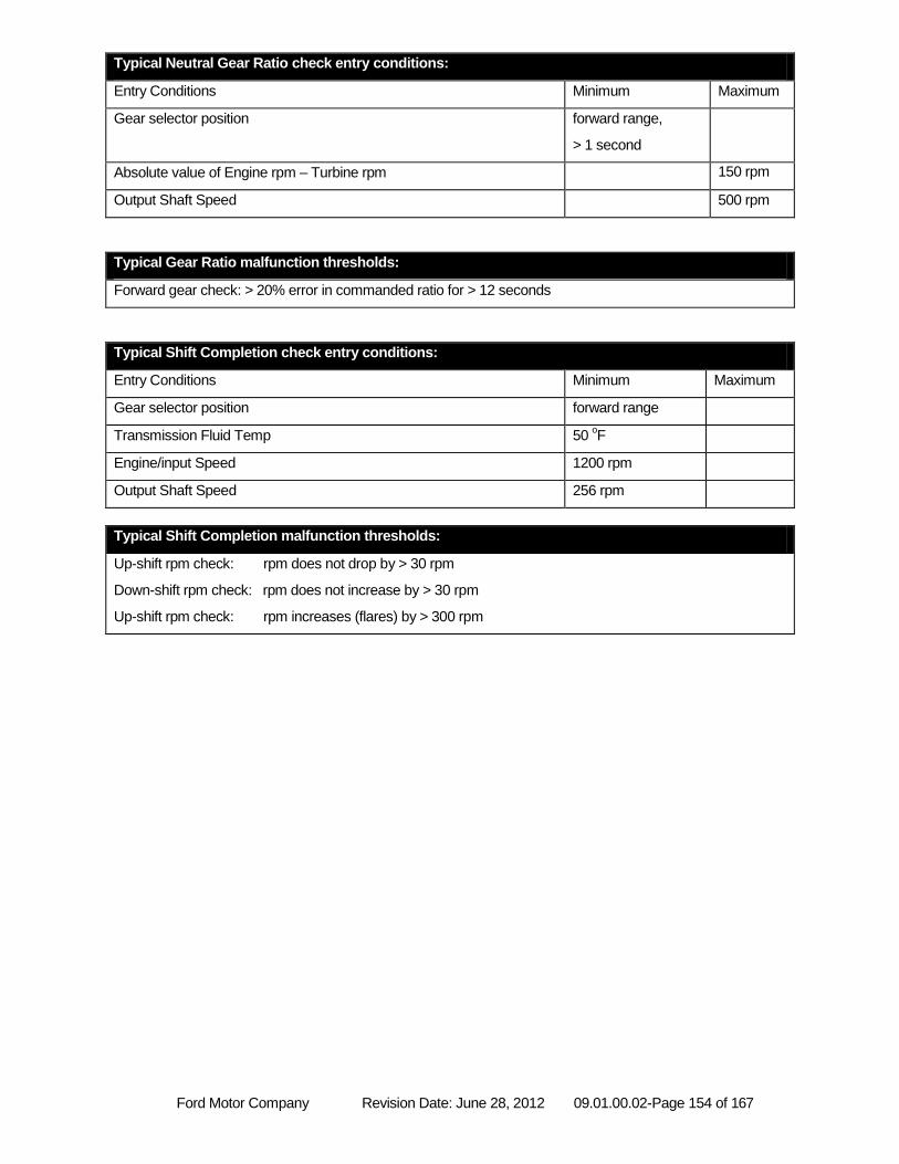
Ford Motor Company Revision Date: June 28, 2012 09.01.00.02-Page 154 of 167
Typical Neutral Gear Ratio check entry conditions:
Entry Conditions Minimum Maximum
Gear selector position forward range,
> 1 second
Absolute value of Engine rpm – Turbine rpm 150 rpm
Output Shaft Speed 500 rpm
Typical Gear Ratio malfunction thresholds:
Forward gear check: > 20% error in commanded ratio for > 12 seconds
Typical Shift Completion check entry conditions:
Entry Conditions Minimum Maximum
Gear selector position forward range
Transmission Fluid Temp 50 oF
Engine/input Speed 1200 rpm
Output Shaft Speed 256 rpm
Typical Shift Completion malfunction thresholds:
Up-shift rpm check: rpm does not drop by > 30 rpm
Down-shift rpm check: rpm does not increase by > 30 rpm
Up-shift rpm check: rpm increases (flares) by > 300 rpm
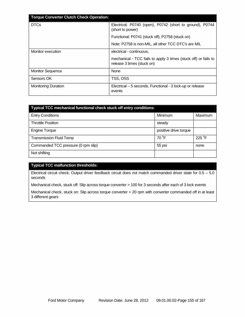
Ford Motor Company Revision Date: June 28, 2012 09.01.00.02-Page 155 of 167
Torque Converter Clutch Check Operation:
DTCs Electrical: P0740 (open), P0742 (short to ground), P0744
(short to power)
Functional: P0741 (stuck off), P2758 (stuck on)
Note: P2758 is non-MIL, all other TCC DTC's are MIL
Monitor execution electrical - continuous,
mechanical - TCC fails to apply 3 times (stuck off) or fails to
release 3 times (stuck on)
Monitor Sequence None
Sensors OK TSS, OSS
Monitoring Duration Electrical – 5 seconds, Functional - 3 lock-up or release
events
Typical TCC mechanical functional check stuck off entry conditions:
Entry Conditions Minimum Maximum
Throttle Position steady
Engine Torque positive drive torque
Transmission Fluid Temp 70 oF 225
oF
Commanded TCC pressure (0 rpm slip) 55 psi none
Not shifting
Typical TCC malfunction thresholds:
Electrical circuit check: Output driver feedback circuit does not match commanded driver state for 0.5 – 5.0
seconds
Mechanical check, stuck off: Slip across torque converter > 100 for 3 seconds after each of 3 lock events
Mechanical check, stuck on: Slip across torque converter < 20 rpm with converter commanded off in at least
3 different gears
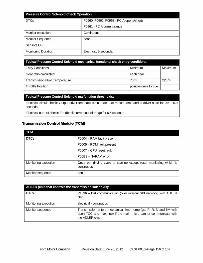
Ford Motor Company Revision Date: June 28, 2012 09.01.00.02-Page 156 of 167
Pressure Control Solenoid Check Operation:
DTCs P0960, P0962, P0963 - PC A opens/shorts
P0961 - PC A current range
Monitor execution Continuous
Monitor Sequence none
Sensors OK
Monitoring Duration Electrical: 5 seconds,
Typical Pressure Control Solenoid mechanical functional check entry conditions:
Entry Conditions Minimum Maximum
Gear ratio calculated each gear
Transmission Fluid Temperature 70 oF 225
oF
Throttle Position positive drive torque
Typical Pressure Control Solenoid malfunction thresholds:
Electrical circuit check: Output driver feedback circuit does not match commanded driver state for 0.5 – 5.0
seconds
Electrical current check: Feedback current out of range for 0.5 seconds
Transmission Control Module (TCM)
TCM
DTCs P0604 – RAM fault present
P0605 – ROM fault present
P0607 – CPU reset fault
P06B8 – NVRAM error
Monitoring execution Once per driving cycle at start-up except reset monitoring which is
continuous
Monitor sequence non
ADLER (chip that controls the transmission solenoids):
DTCs P1636 – lost communication (over internal SPI network) with ADLER
chip
Monitoring execution electrical - continuous
Monitor sequence Transmission enters mechanical limp home (get P, R, N and 5M with
open TCC and max line) if the main micro cannot communicate with
the ADLER chip
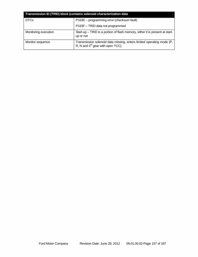
Ford Motor Company Revision Date: June 28, 2012 09.01.00.02-Page 157 of 167
Transmission ID (TRID) block (contains solenoid characterization data
DTCs P163E – programming error (checksum fault)
P163F – TRID data not programmed
Monitoring execution Start-up – TRID is a portion of flash memory, either it is present at start-
up or not
Monitor sequence Transmission solenoid data missing, enters limited operating mode (P,
R, N and 3rd gear with open TCC).
Ford Motor Company Revision Date: June 28, 2012 09.01.00.02-Page 158 of 167
6R140 (RWD) Transmission with external PCM or TCM
Transmission Control System Architecture
Starting in 2011 MY 6R140 replaces 5R110W in Super Duty truck applications.
The 6R140 is a 6-speed, step ratio transmission that is controlled by an external PCM (gas engine applications) or
TCM (Diesel engine applications). For Diesel the TCM communicates to the Engine Control Module (ECM), ABS
Module, Instrument Cluster and Transfer Case Control Module using the high speed CAN communication link. The
TCM incorporates a standalone OBD-II system. The TCM independently processes and stores fault codes, freeze
frame, supports industry-standard PIDs as well as J1979 Mode 09 CALID and CVN. The TCM does not directly
illuminate the MIL, but requests the ECM to do so. The TCM is located outside the transmission assembly. It is not
serviceable with the exception of reprogramming.
Transmission Inputs
Transmission Range Sensor
6R140 uses a Non-contacting Pulse Width Modulated Transmission Range Sensor (TRS) that provides a duty
cycle signal for each position. This signal is transmitted at a frequency of 125 Hz. The PCM / TCM decode the duty
cycle to determine the driver-selected gear position (Park, Rev, Neutral, OD, 3, 2, 1). This input device is checked
for frequency out of range (P0706), duty cycle out of range low (P0707) and duty cycle out of range high (P0708)
Speed Sensors
The Turbine Shaft Speed (TSS) sensor and Output Shaft Speed (OSS) sensor are Hall effect sensors.
The Turbine Shaft Speed sensor is monitored by a rationality test, if engine speed and output shaft speed are high
and a gear is engaged, it can be inferred that the vehicle is moving. If there is insufficient output from the TSS
sensor a fault is stored (P0715).
The Output Shaft Speed sensor is monitored by a rationality test. If engine speed and turbine speed are high and a
gear is engaged, it can be inferred that the vehicle is moving. If there is insufficient output from the OSS sensor a
fault is stored (P0720).
Transmission Fluid Temperature
The Transmission Fluid Temperature Sensor is checked for out of range low (P0712), out of range high (P0713),
and in-range failures (P0711). P1783 sets if TFT exceeds 275 deg F for 5 seconds, indicating transmission
overtemperature (non-MIL failure).
Ford Motor Company Revision Date: June 28, 2012 09.01.00.02-Page 159 of 167
Transmission Outputs
Shift Solenoids (SS)
6R140 has 5 shift solenoids:
SSA – a Variable Force Solenoid (VFS) that controls CB1234 (a brake clutch, grounds an element to the
case, that is on in 1st, 2
nd, 3
rd and 4
th gear)
SSB – a VFS that controls C35R (a rotating clutch on in 3rd, 5
th and Reverse)
SSC – a VFS that controls CB26 (a brake clutch on in 2nd
and 6th gear)
SSD – a VFS that controls CBLR (a brake clutch on in 1st gear with engine braking and Reverse)
SSE – a VFS that controls C456 (a rotating clutch on in 4th, 5
th and 6
th gear)
Output circuits are checked for opens, short to ground and short to power faults (codes listed in that order) by the
"smart driver" (see ADLER below) that controls the solenoids (SSA P0750, P0973, P0974; SSB P0755, P0976,
P0977; SSC P0760, P0979, P0980; SSD P0765, P0982, P0983; SSE P0770, P0985, P0986).
The shift solenoids are also functional tested for stuck on and stuck off failures. This is determined by vehicle
inputs such as gear command, and achieved gear (based on turbine and output speed). In general the shift
solenoid malfunction codes actually cover the entire clutch system (solenoid, valves, seals and the clutch itself
since using ratio there is no way to isolate the solenoid from the rest of the clutch system)
For SSA thru SSE Diagnostics will isolate the fault into clutch functionally (non-electrical) failed off (SSA P0751,
SSB P0756, SSC P0761, SSD P0766. SSE P0771) and clutch functionally failed on (SSA: P0752, SSB: P0757,
SSC: P0762, SSD: P0767, SSE: P0772).
Gear ratio errors:
If ratio errors are detected that do not match an expected pattern for a failed solenoid then gear ratio error fault
codes (1st gear – P0731, 2
nd gear – P0732, 3
rd gear – P0733, 4
th gear – P0734, 5
th gear – P0735 or 6
th gear –
P0729) will be stored.
Torque Converter Clutch
The Torque Converter Clutch (TCC) solenoid is a Variable Force Solenoid. TCC solenoid circuit is checked
electrically for open, short to ground and short to power circuit faults internally by the "smart driver" that controls the
solenoids (P0740, P0742, P0744).
The TCC solenoid is checked functionally for stuck off faults by evaluating torque converter slip under steady state
conditions when the torque converter is fully applied. If the slip exceeds the malfunction thresholds when the TCC
is commanded on, a TCC malfunction is indicated (P0741).
The TCC solenoid is monitored functionally for stuck on faults (P2758) by monitoring for lack of clutch slip when the
TCC is commanded off, but this code is non-MIL because while a stuck on TCC solenoid may cause driveability
complaints and/or cause engine stalls it does not impact emissions or fuel economy.
Electronic Pressure Control (EPC)
The EPC solenoid is a variable force solenoid that controls line pressure in the transmission. The EPC solenoid is
monitored for open, short to ground or short to power faults by the "smart driver" that controls the solenoid. If a
short to ground (low pressure) is detected, a high side switch will be opened. This switch removes power from all 7
VFSs, providing Park, Reverse, Neutral, and 5M (in all forward ranges) with maximum line pressure based on
manual lever position. This solenoid is tested for open (P0960), short to ground (P0962), and short to power
(P0963) malfunctions.
Ford Motor Company Revision Date: June 28, 2012 09.01.00.02-Page 160 of 167
Transmission Solenoid Power Controll (TSPC)
6F140 PCM or TCM has a internal high side switch called TSPC that can be used to remove power from all 7
solenoids simultaneously. If the high side switch is opened, all 7 solenoids will be electrically off, providing Park,
Reverse, Neutral, and 5M (in all forward ranges) with maximum line pressure based on manual lever position.
Due to current limitations TSPC is split into 2 pins / wires at the PCM / TCM. TSPC A provides power to SSA, SSC
and SSE. TSPC B provides power to SSB, SSD, TCC and LPC. Each wire can be tested independently; P0657
sets for an issue with TSPC-A, P2669 sets for an issue with TPSC-B.
Although there are 2 pins and wires between the PCM / TCM and the transmission bulkhead connector the PCM /
TCM contains only one TSPC internally – so the FMEM for either wire being failed is to open TSCP inside the
PCM / TCM, which removes power from all 7 solenoids, providing P, R, N and 5th gear with open TCC and max
line as FMEM for any TPSC faults.
ADLER (chip that controls all 7 solenoids) diagnostics:
The solenoids are controlled by an ADLER chip. The main micro sends commanded solenoid states to the
ADLER, and receives back solenoid circuit fault information.
If communication with the ADLER is lost a P1636 fault code will be stored. If this failure is detected the states of the
solenoids are unknown, so the control system will open the high side switch (removes power from all the
solenoids), providing P, R, N and 5M with open TCC and max line pressure.
TRID Block
The TRID block is a portion of flash memory that contains solenoid characterization data tailored to the specific
transmission to improve pressure accuracy.
The TRID block is monitored for two failures:
TRID block checksum error / incorrect version of the TRID (P163E)
TRID block not programmed (P163F)
If the TRID block is unavailable FMEM action limits operation to P, R, N and 3rd gear based on manual lever
position until the issue is correct.
Transmission Control Module (TCM – Diesel only)
The TCM has the same module diagnostics as a PCM:
P0604 - Powertrain Control Module Random Access Memory (RAM) Error indicates the Random Access
Memory read/write test failed.
P0605 - Powertrain Control Module Read Only Memory (ROM) Error indicates a Read Only Memory
check sum test failed.
P0607 - Powertrain Control Module Performance indicates incorrect CPU instruction set operation, or
excessive CPU resets.
P06B8 - Internal Control Module Non-Volatile Random Access Memory (NVRAM) Error indicates
Permanent DTC check sum test failed
.
Ford Motor Company Revision Date: June 28, 2012 09.01.00.02-Page 161 of 167
CAN Communications Error
The TCM receives information from the ECM via the high speed CAN network. If the CAN link or network fails, the
TCM no longer has torque or engine speed information available. The TCM will store a U0073 fault code and will
illuminate the MIL immediately (missing engine speed) if the CAN Bus is off. The TCM will store a U0100 fault code
and will illuminate the MIL immediately (missing engine speed) if it stops receiving CAN messages from the ECM.
A U0401 fault codes will be stored if the ECM sends invalid/faulted information for the following CAN message
items: engine torque, pedal position.
TCM voltage
If the system voltage at the TCM is outside of the specified 9 to 16 volt range, a fault will be stored (P0882, P0883).
Ford Motor Company Revision Date: June 28, 2012 09.01.00.02-Page 162 of 167
On Board Diagnostic Executive
The On-Board Diagnostic (OBD) Executive is a portion of the PCM strategy that manages the diagnostic trouble codes and operating modes for all diagnostic tests. It is the "traffic cop" of the diagnostic system. The Diagnostic Executive performs the following functions:
Stores freeze frame and "similar condition" data.
Manages storage and erasure of Diagnostic Trouble Codes as well as MIL illumination.
Controls and co-ordinates the execution of the On-Demand tests: Key On Engine Off (KOEO) and Key On Engine Running (KOER).
Performs transitions between various states of the diagnostic and powertrain control system to minimize the effects on vehicle operation.
Interfaces with the diagnostic test tools to provide diagnostic information (I/M readiness, various J1979 test modes) and responses to special diagnostic requests (J1979 Mode 08 and 09).
Tracks and manages indication of the driving cycle which includes the time between two key on events that include an engine start and key off.
The diagnostic executive also controls several overall, global OBD entry conditions.
The battery voltage must fall between 9.0 and 16.25 volts to initiate monitoring cycles.
The engine must be started to initiate the engine started, engine running, and engine off monitoring cycles.
The Diagnostic Executive suspends OBD monitoring when battery voltage falls below 11.0 volts.
The diagnostic executive controls the setting and clearing of pending and confirmed DTCs.
A pending DTC and freeze frame data is stored after a fault is confirmed on the first monitoring cycle. If the
fault recurs on the next driving cycle, a confirmed DTC is stored, freeze frame data is updated, and the
MIL is illuminated. If confirmed fault free on the next driving cycle, the pending DTC and freeze frame data
is erased on the next power-up.
Pending DTCs will be displayed as long as the fault is present. Note that OBD-II regulations required a
complete fault-free monitoring cycle to occur before erasing a pending DTC. In practice, this means that a
pending DTC is erased on the next power-up after a fault-free monitoring cycle.
After a confirmed DTC is stored and the MIL has been illuminated, three consecutive confirmed fault-free
monitoring cycles must occur before the MIL can be extinguished on the next (fourth) power-up. After 40
engine warm-ups, the DTC and freeze frame data is erased.
The diagnostic executive controls the setting and clearing of permanent DTCs.
A permanent DTC is stored when a confirmed DTC is stored, the MIL has been illuminated, and there are
not yet six permanent DTCs stored.
After a permanent DTC is stored, three consecutive confirmed fault-free monitoring cycles must occur
before the permanent DTC can be erased.
After a permanent DTC is stored, one confirmed fault-free monitoring cycle must occur, following a DTC
reset request, before the permanent DTC can be erased. For 2010MY and beyond ISO 14229 programs
a driving cycle including the following criteria must also occur, following the DTC reset request, before a
permanent DTC can be erased: o Cumulative time since engine start is greater than or equal to 600 seconds; o Cumulative vehicle operation at or above 25 miles per hour occurs for greater than or equal
to 300 seconds (medium-duty vehicles with diesel engines certified on an engine dynamometer may use cumulative operation at or above 15% calculated load in lieu of at or above 25 miles per hour for purposes of this criteria); and
o Continuous vehicle operation at idle (i.e., accelerator pedal released by driver and vehicle speed less than or equal to one mile per hour) for greater than or equal to 30 seconds.
A permanent DTC can not be erased by a KAM clear (battery disconnect). Additionally, its confirmed DTC
counterpart will be restored after completion of the KAM reset (battery reconnect).
Ford Motor Company Revision Date: June 28, 2012 09.01.00.02-Page 163 of 167
Exponentially Weighted Moving Average
Exponentially Weighted Moving Averaging is a well-documented statistical data processing technique that is used
to reduce the variability on an incoming stream of data. Use of EWMA does not affect the mean of the data;
however, it does affect the distribution of the data. Use of EWMA serves to “filter out” data points that exhibit
excessive and unusual variability and could otherwise erroneously light the MIL.
The simplified mathematical equation for EWMA implemented in software is as follows:
New Average = [New data point * “filter constant”] + [( 1 - “filter constant” ) * Old Average]
This equation produces an exponential response to a step-change in the input data. The "Filter Constant"
determines the time constant of the response. A large filter constant (i.e. 0.90) means that 90% of the new data
point is averaged in with 10% of the old average. This produces a very fast response to a step change.
Conversely, a small filter constant (i.e. 0.10) means that only 10% of the new data point is averaged in with 90%
of the old average. This produces a slower response to a step change.
When EWMA is applied to a monitor, the new data point is the result from the latest monitor evaluation. A new
average is calculated each time the monitor is evaluated and stored in Keep Alive Memory (KAM). This normally
occurs each driving cycle. The MIL is illuminated and a DTC is stored based on the New Average store in KAM.
In order to facilitate repair verification and DDV demonstration, 2 different filter constants are used. A “fast filter
constant” is used after KAM is cleared/DTCs are erased and a “normal filter constant” is used for normal
customer driving. The “fast filter” is used for 2 driving cycles after KAM is cleared/DTCs are erased, and then the
“normal filter” is used. The “fast filter” allows for easy repair verification and monitor demonstration in 2 driving
cycles, while the normal filter is used to allow up to 6 driving cycles, on average, to properly identify a malfunction
and illuminate the MIL.
In order to relate filter constants to driving cycles for MIL illumination, filter constants must be converted to time
constants. The mathematical relationship is described below:
Time constant = [ ( 1 / filter constant ) - 1 ] * evaluation period
The evaluation period is a driving cycle. The time constant is the time it takes to achieve 68% of a step-change to
an input. Two time constants achieve 95% of a step change input.
Ford Motor Company Revision Date: June 28, 2012 09.01.00.02-Page 164 of 167
Serial Data Link MIL Illumination
The OBD-II diagnostic communication messages utilize an industry standard 500 kbps CAN communication link.
The instrument cluster on some vehicles uses the same CAN data link to receive and display various types of
information from the PCM. For example, the engine coolant temperature information displayed on the instrument
cluster comes from the same ECT sensor used by the PCM for all its internal calculations.
These same vehicles use the CAN data link to illuminate the MIL rather than a circuit, hard-wired to the PCM.
The PCM periodically sends the instrument cluster a message that tells it to turn on the MIL, turn off the MIL or
blink the MIL. If the instrument cluster fails to receive a message within a 5-second timeout period, the instrument
cluster itself illuminates the MIL. If communication is restored, the instrument cluster turns off the MIL after 5
seconds. Due to its limited capabilities, the instrument cluster does not generate or store Diagnostic Trouble
Codes.
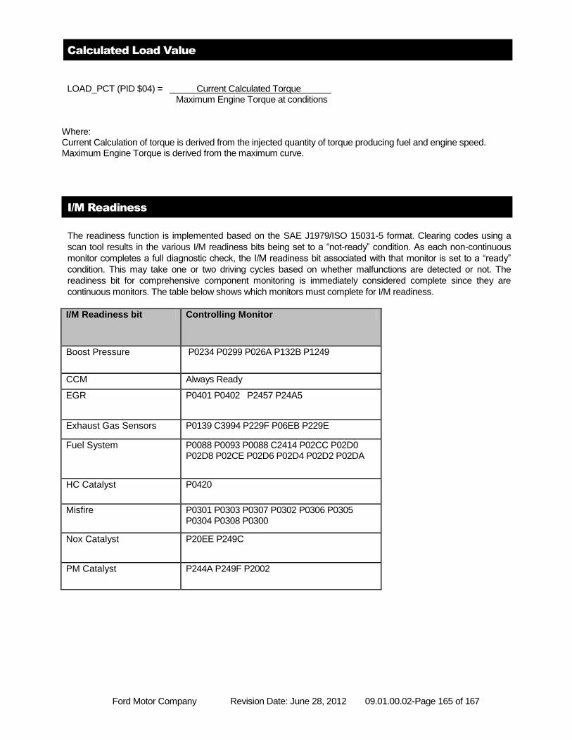
Ford Motor Company Revision Date: June 28, 2012 09.01.00.02-Page 165 of 167
Calculated Load Value
LOAD_PCT (PID $04) = Current Calculated Torque Maximum Engine Torque at conditions
Where: Current Calculation of torque is derived from the injected quantity of torque producing fuel and engine speed. Maximum Engine Torque is derived from the maximum curve.
I/M Readiness
The readiness function is implemented based on the SAE J1979/ISO 15031-5 format. Clearing codes using a
scan tool results in the various I/M readiness bits being set to a “not-ready” condition. As each non-continuous
monitor completes a full diagnostic check, the I/M readiness bit associated with that monitor is set to a “ready”
condition. This may take one or two driving cycles based on whether malfunctions are detected or not. The
readiness bit for comprehensive component monitoring is immediately considered complete since they are
continuous monitors. The table below shows which monitors must complete for I/M readiness.
I/M Readiness bit Controlling Monitor
Boost Pressure P0234 P0299 P026A P132B P1249
CCM Always Ready
EGR P0401 P0402 P2457 P24A5
Exhaust Gas Sensors P0139 C3994 P229F P06EB P229E
Fuel System P0088 P0093 P0088 C2414 P02CC P02D0 P02D8 P02CE P02D6 P02D4 P02D2 P02DA
HC Catalyst P0420
Misfire P0301 P0303 P0307 P0302 P0306 P0305 P0304 P0308 P0300
Nox Catalyst P20EE P249C
PM Catalyst P244A P249F P2002
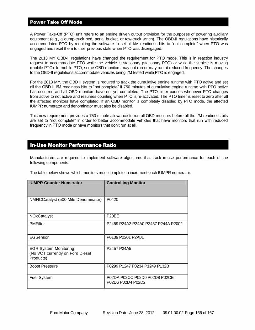
Ford Motor Company Revision Date: June 28, 2012 09.01.00.02-Page 166 of 167
Power Take Off Mode
A Power Take-Off (PTO) unit refers to an engine driven output provision for the purposes of powering auxiliary equipment (e.g., a dump-truck bed, aerial bucket, or tow-truck winch). The OBD-II regulations have historically accommodated PTO by requiring the software to set all I/M readiness bits to "not complete" when PTO was engaged and reset them to their previous state when PTO was disengaged. The 2013 MY OBD-II regulations have changed the requirement for PTO mode. This is in reaction industry request to accommodate PTO while the vehicle is stationary (stationary PTO) or while the vehicle is moving (mobile PTO). In mobile PTO, some OBD monitors may not run or may run at reduced frequency. The changes to the OBD-II regulations accommodate vehicles being I/M tested while PTO is engaged. For the 2013 MY, the OBD II system is required to track the cumulative engine runtime with PTO active and set all the OBD II I/M readiness bits to “not complete” if 750 minutes of cumulative engine runtime with PTO active has occurred and all OBD monitors have not yet completed. The PTO timer pauses whenever PTO changes from active to not active and resumes counting when PTO is re-activated. The PTO timer is reset to zero after all the affected monitors have completed. If an OBD monitor is completely disabled by PTO mode, the affected IUMPR numerator and denominator must also be disabled. This new requirement provides a 750 minute allowance to run all OBD monitors before all the I/M readiness bits are set to “not complete” in order to better accommodate vehicles that have monitors that run with reduced frequency in PTO mode or have monitors that don’t run at all.
In-Use Monitor Performance Ratio
Manufacturers are required to implement software algorithms that track in-use performance for each of the
following components:
The table below shows which monitors must complete to increment each IUMPR numerator.
IUMPR Counter Numerator Controlling Monitor
NMHCCatalyst (500 Mile Denominator) P0420
NOxCatalyst P20EE
PMFilter P2459 P24A2 P24A0 P2457 P244A P2002
EGSensor P0139 P2201 P2A01
EGR System Monitoring (No VCT currently on Ford Diesel Products)
P2457 P24A5
Boost Pressure P0299 P1247 P0234 P1249 P132B
Fuel System P02DA P02CC P02D0 P02D8 P02CE P02D6 P02D4 P02D2
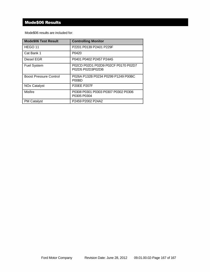
Ford Motor Company Revision Date: June 28, 2012 09.01.00.02-Page 167 of 167
Mode$06 Results
Mode$06 results are included for:
Mode$06 Test Result Controlling Monitor
HEGO 11 P2201 P0139 P2A01 P229F
Cat Bank 1 P0420
Diesel EGR P0401 P0402 P2457 P24A5
Fuel System P02CD P02D1 P02D9 P02CF P0170 P02D7 P02D5 P02D3P02DB
Boost Pressure Control P026A P132B P0234 P0299 P1249 P00BC P00BD
NOx Catalyst P20EE P207F
Misfire P0308 P0301 P0303 P0307 P0302 P0306 P0305 P0304
PM Catalyst P2459 P2002 P24A2