2013-2015 Altima and 2014-2016 Rogue; MIL ON With DTC P0776
16
1/16 Classification: Reference: Date: AT15-015a NTB15-086a November 11, 2015 2013-2015 ALTIMA AND 2014-2016 ROGUE; MIL ON WITH DTC P0776 The Parts Information and the Claims Information in this bulletin have been amended. Please discard previous versions of this bulletin. APPLIED VEHICLES: 2013-2015 Altima (L33) with 4-cyl engine only 2014-2016 Rogue (T32) NOTE: Does not apply to Rogue Select (S35) IF YOU CONFIRM: The MIL is ON and ONLY DTC P0776 (PC SOLENOID B – Pressure Control Solenoid “B” Performance/Stuck OFF) is stored in the TCM. NOTE: If this issue should occur, the vehicle may hesitate and/or have a lack of power. ACTION: Refer to the Repair Flow Chart on page 2. NOTE: Essential Tool Tech Cam (borescope) J-51951, which is used for CVT inspection, has been sent to dealers. This tool’s attachements make CVT inspection possible. IMPORTANT: The purpose of ACTION (above) is to give you a quick idea of the work you will be performing. You MUST closely follow the entire SERVICE PROCEDURE as it contains information that is essential to successfully completing this repair. Nissan Bulletins are intended for use by qualified technicians, not 'do-it-yourselfers'. Qualified technicians are properly trained individuals who have the equipment, tools, safety instruction, and know-how to do a job properly and safely. NOTE: If you believe that a described condition may apply to a particular vehicle, DO NOT assume that it does. See your Nissan dealer to determine if this applies to your vehicle.
Transcript of 2013-2015 Altima and 2014-2016 Rogue; MIL ON With DTC P0776

1/16
Classification: Reference: Date:
AT15-015a NTB15-086a November 11 , 2015
2013-2015 ALTIMA AND 2014-2016 ROGUE; MIL ON WITH DTC P0776
The Parts Information and the Claims Information in this bulletin have been amended.
Please discard previous versions of this bulletin. APPLIED VEHICLES: 2013-2015 Altima (L33) with 4-cyl engine only
2014-2016 Rogue (T32)
NOTE: Does not apply to Rogue Select (S35)
IF YOU CONFIRM: The MIL is ON and ONLY DTC P0776 (PC SOLENOID B – Pressure Control Solenoid “B” Performance/Stuck OFF) is stored in the TCM.
NOTE: If this issue should occur, the vehicle may hesitate and/or have a lack of power.
ACTION:
Refer to the Repair Flow Chart on page 2.
NOTE: Essential Tool Tech Cam (borescope) J-51951, which is used for CVT inspection, has been sent to dealers. This tool’s attachements make CVT inspection possible.
IMPORTANT: The purpose of ACTION (above) is to give you a quick idea of the work you will be performing. You MUST closely follow the entire SERVICE PROCEDURE as it contains information that is essential to successfully completing this repair.
Nissan Bulletins are intended for use by qualified technicians, not 'do-it-yourselfers'. Qualified technicians are properly trained individuals who have the equipment, tools, safety instruction, and know-how to do a job properly and safely. NOTE: If you believe that a described condition may apply to a particular vehicle, DO NOT assume that it does. See your Nissan dealer to determine if this applies to your vehicle.

Repair Flow Chart
Replace the CVT assembly
See page 16 for important
pre-authorization information
Replace the valve body and oil pan,
add one magnet
Evidence of CVT belt slippage
Remove the control valve (valve body),
inspect the CVT belt
The CVT belt checks out OK
MIL ON with DTC P0776 stored
Vehicle may hesitate and/or lack power
2/16 NTB15-086a

SERVICE PROCEDURE
Exploded View
(Total of 9 bolts)
Figure 1
Transaxle (CVT) assembly Terminal cord assembly Control valve (valve body)
Bracket O-ring Oil strainer assembly
Oil pan gasket
Oil pan
Drain plug
Drain plug gasket
Two original magnets
Spring washer
Manual plate Lip seal
Snap ring
Overflow plug
O-ring
3/16 NTB15-086a

Control Valve (Valve Body) Removal and CVT Belt Inspection 1. Remove the valve body.
Before lifting the vehicle: Place the transmission gear selector in Neutral. Leave the driver door unlatched. A step further in the procedure may require it.
For Altima: Refer to the appropriate ESM, section TM – Transaxle & Transmission, for valve body removal.
For Rogue: Refer to the 2013 Altima ESM, section TM – Transaxle & Transmission / RE0F10D, for valve body removal.
NOTE: The number ‘7’ is on the head of all bolts that need to be removed for valve body removal. Do not remove any bolt that does not have the number ‘7’.
CAUTION: Never allow any chemicals or fluids other than NS-3 CVT fluid or equivalent to enter the CVT assembly. Never allow any foreign debris, dust, dirt, etc. to enter the CVT assembly.
For additional information, see video # 544: “CVT Belt Inspection”. This video is located under the TECH TRAINING GARAGE VIDEOS tab in Virtual Academy.
4/16 NTB15-086a

Figure 2
Figure 3
Figure 4
2. Secure the front right tire with a suitable strap.
This will assist in making the belt turn.
3. Mark the front left tire with a suitable
marking.
This will assure all 360° of the belt is inspected.
4. Using borescope J-51951 with mirror attachment, inspect the entirety of the two sides of the belt that come in contact with the pulleys (see page 7, Figure 8).
Reference the pictures on pages 7 thourgh 11 for comparison.
NOTE:
Be sure to remove the protective film from the mirror before the first use.
Clean the camera lens and mirror before each inspection. Use 90% isopropyl alcohol, and a lens swab from Lens Swab packet J-51963 listed in PARTS INFORMATION.
Before inspecting, make sure the camera handle’s AA batteries are fresh and the LCD monitor’s battery is charged.
a. Insert the camera lens between the CVT case and pulley where shown in Figures 3 and 4.
Insert the lens approximately seven (7) inches, and then view the side of the belt that contacts the pulley.
Belt
Pulley
Case
Step 4cStep 4a
Camera flexible tube
Front
5/16 NTB15-086a

b. Slowly and carefully turn the front left tire one full turn in the forward rotation to view all of the belt.
Holding the borescope with one hand allows for turning the tire with the other hand (see Figure 5).
CAUTION: If the tire is rotated in the rearward rotation, the camera lens may get caught between the belt and pulley.
c. If the inspection result is OK, inspect the other side of the belt.
Insert the camera lens in the second location where shown in Figure 3 and 6, and then perform step 4b again.
d. If the inspection result is OK 360° on both sides of the belt, skip to step 5 on the next page.
If any evidence of belt slippage is found, go to step 4e, and then step 6.
For additional information, see video # 544: “CVT Belt Inspection”. This video is located under the TECH TRAINING GARAGE VIDEOS tab in Virtual Academy.
e. Once CVT replacement is determined as required, use borescope J-51951 to record a 15 second or less continuous video of the most severe evidence of belt slip and the VIN on the F.M.V.S.S.certification label (VIN label). See Figure 7.
NOTE: This required video must be attached to the Powertrain Call Center CVT Preauthorization Form (in ASIST)prior to calling for authorization. Failure to submit a continuous video will cause immediate denial of request for replacement.
Figure 5
Pulley
Front
Figure 6
VIN label
Figure 7
6/16 NTB15-086a

Before starting to record, make sure the camera handle’s AA batteries are fresh and
the LCD monitor’s battery is charged. The whole video will show as backward, or reversed mirror image. This is okay. The required video must show clear evidence of belt slippage and be 15 seconds or
less.
5. If the belt inspection result is OK, replace the valve body.
There is no need for pictures or video showing “OK” belt surfaces. For valve body replacement, go to page 12, Control Valve (Valve Body)
Installation.
6. If the belt inspection result is NG, replace the CVT assembly.
Get authorization to replace the CVT assembly (see page 16). Make sure to perform step 4e on page 6. For CVT assembly replacement, refer to the appropriate ESM, section TM –
Transaxle & Transmission / RE0F10D.
IMPORTANT: Perform "ADDITIONAL SERVICE WHEN REPLACING TRANSAXLE ASSEMBLY".
Refer to TM – Transaxle & Transmission / RE0F10D / BASIC INSPECTION:
o Check for fluid leakage. o Install Write IP Characteristics to the TCM.
The CVT unit requiring replacement will need to be reassembled for Nissan parts return/collection.
7. Flush the CVT cooler(s).
IMPORTANT: A CVT Cooler flush is required after a valve body or CVT assembly replacement. Refer to bulletin NTB15-013 to perform CVT Cooler flush.
Inspect these sides
Do not inspect these sides
Figure 8
7/16 NTB15-086a
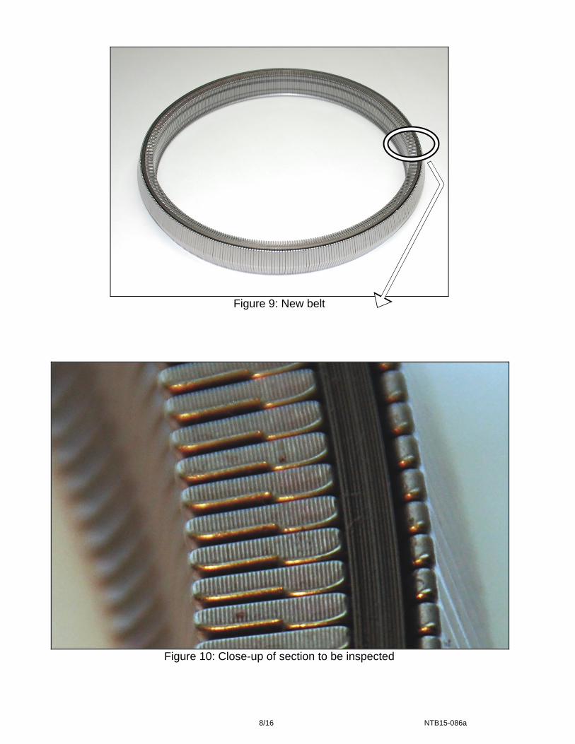
Figure 9: New belt
Figure 10: Close-up of section to be inspected
8/16 NTB15-086a

Pictures in Figures 11 and 12 were taken with borescope J-51951.
OK
Visual lines
Figure 11: Belt is OK
OK
Visual lines
Figure 12: Belt is OK
9/16 NTB15-086a
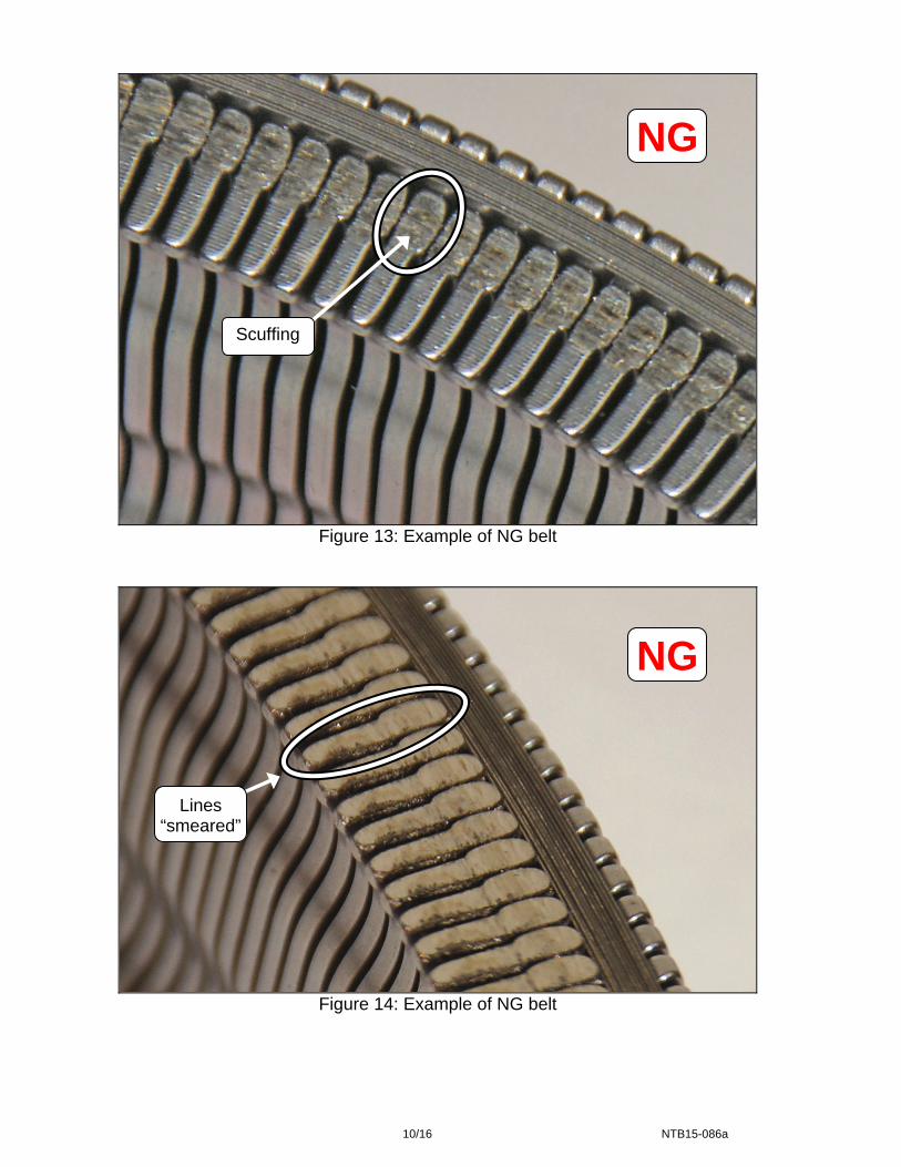
NG
Scuffing
Figure 13: Example of NG belt
NG
Lines “smeared”
Figure 14: Example of NG belt
10/16 NTB15-086a
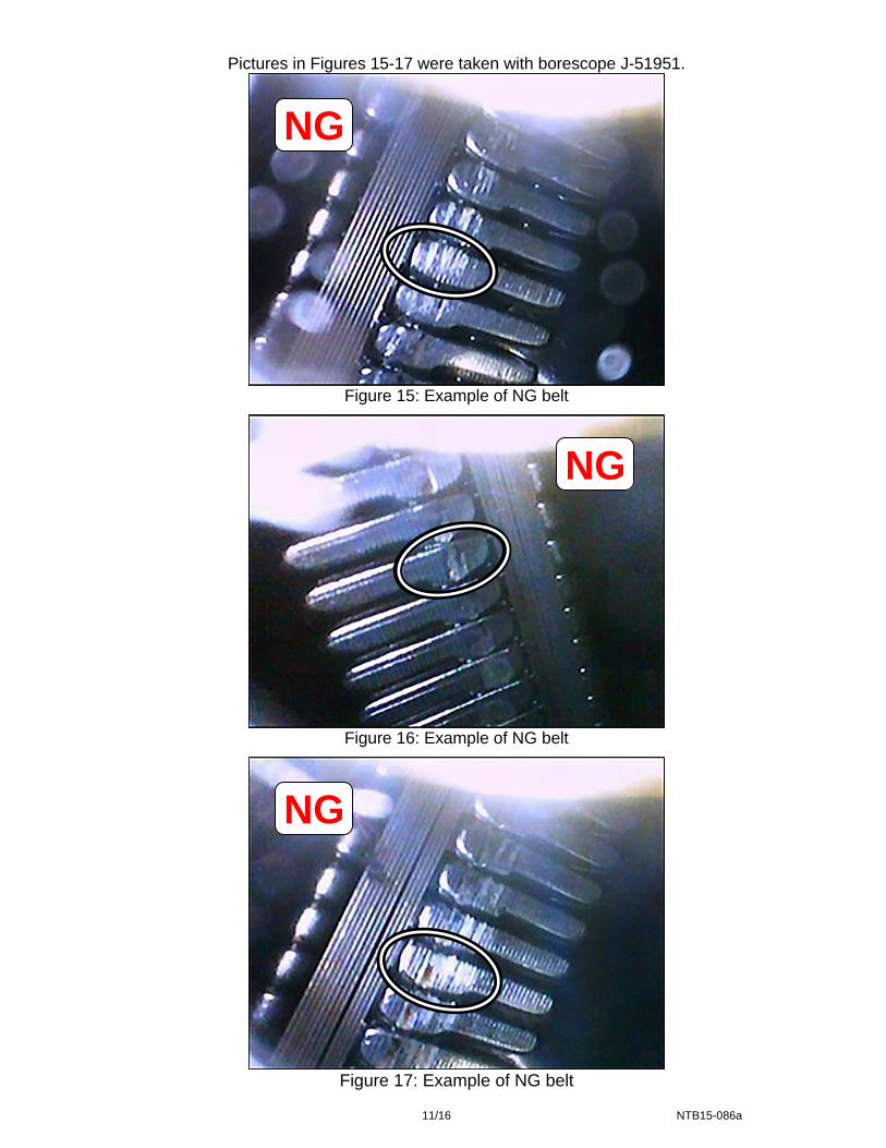
Pictures in Figures 15-17 were taken with borescope J-51951.
NG
Figure 15: Example of NG belt
NG
Figure 16: Example of NG belt
NG
Figure 17: Example of NG belt
11/16 NTB15-086a

Control Valve (Valve Body) Installation
1. Install the valve body.
For Altima: Refer to the appropriate ESM, section TM – Transaxle & Transmission, for valve body installation.
For Rogue: Refer to the 2013 Altima ESM, section TM – Transaxle & Transmission / RE0F10D, for valve body installation.
NOTE: Make sure the oil strainer and O-ring are replaced.
CAUTION: Never allow any chemicals or fluids other than NS-3 CVT fluid or equivalent to enter the CVT assembly. Never allow any foreign debris, dust, dirt, etc. to enter the CVT assembly.
2. Install a new style oil pan with the addition of a third magnet.
Additional magnet is listed in the PARTS INFORMATION.
Refer to the ESM, section TM-Transaxle & Transmission, for oil pan installation.
CAUTION: Never allow any chemicals or fluids other than NS-3 CVT fluid or equivalent to enter the CVT assembly. Never allow any foreign debris, dust, dirt, etc. to enter the CVT assembly.
Install the one additional magnet and two existing magnets where shown in Figure 18.
Make sure the new oil pan and magnets are thoroughly clean before installing.
Figure 18
Existing magnets Additional
magnet
12/16 NTB15-086a

3. Fill the CVT assembly with NS-3 CVT fluid or equivalent.
Refer to the ESM, section TM – Transaxle & Transmission / RE0F10D, for CVT fluid filling.
4. IMPORTANT: Install Write IP Characteristics to the TCM.
Refer to TM – Transaxle & Transmission / RE0F10D / BASIC INSPECTION, and perform ADDITIONAL SERVICE WHEN REPLACING TRANSAXLE ASSEMBLY.
Check for fluid leakage. Attach the QR label with the new calibration data onto the transmission range
switch (inhibitor switch).
o See Figure 19 and 20 below.
o A QR Label and CD-R are included with the replacement valve body.
5. Erase the DTC.
Air cleaner intake duct
------
Valve cover -----
QR label
Inhibitor switch
Figure 19 Figure 20
13/16 NTB15-086a

PARTS INFORMATION
DESCRIPTION PART NUMBER QUANTITY CVT ASSEMBLY (1) (2) 1
VALVE ASSEMBLY-CONTROL (valve body) (3)
31705-28X0B 1
STRAINER ASSEMBLY - OIL 31728-1XZ0D 1 PAN ASSY-OIL 31390-3VX0C 1
GASKET-OIL PAN 31397-1XF0D 1 SEAL-LIP 31528-1XZ0A 1 MAGNET 31379-3AX0A 1
WASHER-DRAIN 11026-JA00A 1 SEAL, O-RING (fluid filler plug gasket) 31526-3VX0B 1
NS-3 CVT Fluid (4) (5) 999MP-NS300P As neededLens Swab (6) (7) J-51963 As needed
(1) If the CVT assembly is being replaced, no other parts in the table above, except NS-3 CVT fluid or equivalent, are needed.
(2) Refer to the electronic parts catalog (FAST or equivalent) for the correct part number. (3) Includes QR Label, CD-R, and Control Valve Assembly. (4) For warranty repairs, Nissan NS-3 CVT Fluid must be used. For customer pay repairs,
Nissan NS-3 CVT Fluid or an equivalent is recommended. (5) NS-3 CVT Fluid can be ordered through the Nissan Maintenance Advantage program:
Phone: 877-NIS-NMA1 (877-647-6621) or Website: Order via link on dealer portal www.NNAnet.com and click on the “Maintenance Advantage” link.
(6) Lens swabs are available from Tech•Mate online: www.nissantechmate.com, or by phone: 1-800-662-2001.
(7) Shop supply.
Tech Cam J-51951
Remove protective film before first use
Lens swab J-51963 (not part of J-51951)
Figure 21
Additional kits of Tech Cam J-51951 are available from Tech•Mate online: www.nissantechmate.com, or by phone: 1-800-662-2001.
14/16 NTB15-086a
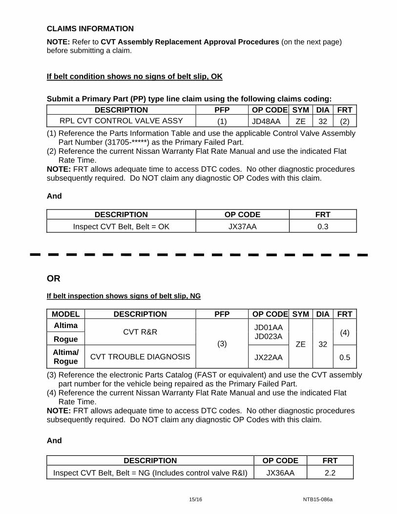
CLAIMS INFORMATION
NOTE: Refer to CVT Assembly Replacement Approval Procedures (on the next page) before submitting a claim.
If belt condition shows no signs of belt slip, OK
Submit a Primary Part (PP) type line claim using the following claims coding:
DESCRIPTION PFP OP CODE SYM DIA FRTRPL CVT CONTROL VALVE ASSY (1) JD48AA ZE 32 (2)
(1) Reference the Parts Information Table and use the applicable Control Valve Assembly Part Number (31705-*****) as the Primary Failed Part.
(2) Reference the current Nissan Warranty Flat Rate Manual and use the indicated Flat Rate Time.
NOTE: FRT allows adequate time to access DTC codes. No other diagnostic procedures subsequently required. Do NOT claim any diagnostic OP Codes with this claim. And
DESCRIPTION OP CODE FRT
Inspect CVT Belt, Belt = OK JX37AA 0.3
OR If belt inspection shows signs of belt slip, NG
MODEL DESCRIPTION PFP OP CODE SYM DIA FRT
Altima CVT R&R
(3)
JD01AA JD023A
ZE 32
(4) Rogue
Altima/ Rogue
CVT TROUBLE DIAGNOSIS JX22AA 0.5
(3) Reference the electronic Parts Catalog (FAST or equivalent) and use the CVT assembly part number for the vehicle being repaired as the Primary Failed Part.
(4) Reference the current Nissan Warranty Flat Rate Manual and use the indicated Flat Rate Time.
NOTE: FRT allows adequate time to access DTC codes. No other diagnostic procedures subsequently required. Do NOT claim any diagnostic OP Codes with this claim.
And
DESCRIPTION OP CODE FRT
Inspect CVT Belt, Belt = NG (Includes control valve R&I) JX36AA 2.2
15/16 NTB15-086a
CVT Assembly Replacement Approval Procedures
If CVT belt inspection indicates CVT assembly replacement is required:
a. Complete the PCC CVT Preauthorization Form in ASIST.
b. Attach the required video (15 seconds or less) to the CVT Preauthorization Form.
Failure to submit a continuous video showing evidence of belt slip and the VIN will cause immediate denial of request for CVT unit replacement.
c. Call the PCC for authorization at 800-973-9992 (opt 2).
IMPORTANT: Make sure the video has a clear image of the VIN on the F.M.V.S.S. certification label (VIN label).
16/16 NTB15-086a