2012 Toyota Camry Owners Manual
499
TABLE OF CONTENTS 1 1 Before driving Adjusting and operating features such as door locks, mirrors, and steering column. 2 When driving Driving, stopping and safe-driving information. 3 Interior fea- tures Air conditioning and audio systems, as well as other in- terior features for a comfortable driving experience. 4 Maintenance and care Cleaning and protecting your vehicle, performing do-it- yourself maintenance, and maintenance information. 5 When trouble arises What to do if the vehicle needs to be towed, gets a flat tire, or is involved in an accident. 6 Vehicle specifications Detailed vehicle information. 7 For owners Reporting safety defects for U.S. owners, and seat belt and SRS airbag instructions for Canadian owners Index Alphabetical listing of information contained in this manual.
-
Upload
aatifsaif80 -
Category
Documents
-
view
258 -
download
12
Transcript of 2012 Toyota Camry Owners Manual

TABLE OF CONTENTS
1
1 Before driving Adjusting and operating features such as door locks, mirrors, and steering column.
2 When driving Driving, stopping and safe-driving information.
3 Interior fea-tures
Air conditioning and audio systems, as well as other in-terior features for a comfortable driving experience.
4 Maintenance and care
Cleaning and protecting your vehicle, performing do-it-yourself maintenance, and maintenance information.
5 When trouble arises
What to do if the vehicle needs to be towed, gets a flat tire, or is involved in an accident.
6 Vehicle specifications Detailed vehicle information.
7 For owners Reporting safety defects for U.S. owners, and seat belt and SRS airbag instructions for Canadian owners
Index Alphabetical listing of information contained in this manual.

19
For your information
Main Owner’s Manual
Please note that this manual covers all models and all equipment, includingoptions. Therefore, you may find some explanations for equipment notinstalled on your vehicle.
All specifications provided in this manual are current at the time of printing.However, because of the Toyota policy of continual product improvement, wereserve the right to make changes at any time without notice.
Depending on specifications, the vehicle shown in the illustrations may differfrom your vehicle in terms of equipment.
Noise from under vehicle after turning off the engine
Approximately five hours after the engine is turned off, you may hear soundcoming from under the vehicle for several minutes. This is the sound of a fuelevaporation leakage check and, it does not indicate a malfunction.
Accessories, spare parts and modification of your Toyota
A wide variety of non-genuine spare parts and accessories for Toyotavehicles are currently available on the market. You should know that Toyotadoes not warrant these products and is not responsible for theirperformance, repair, or replacement, or for any damage they may cause to,or adverse effect they may have on, your Toyota vehicle.
This vehicle should not be modified with non-genuine Toyota products.Modification with non-genuine Toyota products could affect its performance,safety or durability, and may even violate governmental regulations. Inaddition, damage or performance problems resulting from the modificationmay not be covered under warranty.

20
Installation of a mobile two-way radio system
The installation of a mobile two-way radio system in your vehicle could affectelectronic systems such as:
●Multiport fuel injection system /sequential multiport fuel injection system
●Cruise control system
●Anti-lock brake system
●SRS airbag system
●Seat belt pretensioner system
Be sure to check with your Toyota dealer for precautionary measures or spe-cial instructions regarding installation of a mobile two-way radio system.

21
Vehicle data recordings
Your Toyota is equipped with several sophisticated computers that will recordcertain data, such as:
• Engine speed• Accelerator status• Brake status• Vehicle speed• Shift positionThe recorded data varies according to the vehicle grade level and optionswith which it is equipped. Furthermore, these computers do not record con-versations, sounds or pictures.
● Data usage
Toyota may use the data recorded in these computers to diagnose malfunc-tions, conduct research and development, and improve quality.
Toyota will not disclose the recorded data to a third party except:
• With the consent of the vehicle owner or with the consent of the lessee ifthe vehicle is leased
• In response to an official request by the police, a court of law or a govern-ment agency
• For use by Toyota in a law suit• For research purposes where the data is not tied to a specific vehicle or
vehicle owner● Usage of data collected through Safety Connect (U.S.mainland only)
If your Toyota has Safety Connect and if you have subscribed to those ser-vices, please refer to the Safety Connect Telematics Subscription ServiceAgreement for information on data collected and its usage.

22
Event data recorder
This vehicle is equipped with an event data recorder (EDR). The main pur-pose of an EDR is to record, in certain crash or near crash-like situations,such as an air bag deployment or hitting a road obstacle, data that will assistin understanding how a vehicle’s systems performed. The EDR is designedto record data related to vehicle dynamics and safety systems for a shortperiod of time, typically 30 seconds or less.
The EDR in this vehicle is designed to record such data as:
• How various systems in your vehicle were operating;• Whether or not the driver and passenger safety belts were buckled/fas-
tened;• How far (if at all) the driver was depressing the accelerator and/or brake
pedal; and,• How fast the vehicle was traveling.These data can help provide a better understanding of the circumstances inwhich crashes and injuries occur.
NOTE: EDR data are recorded by your vehicle only if a non-trivial crash situ-ation occurs; no data are recorded by the EDR under normal driving condi-tions and no personal data (e.g., name, gender, age, and crash location) arerecorded. However, other parties, such as law enforcement, could combinethe EDR data with the type of personally identifying data routinely acquiredduring a crash investigation. To read data recorded by an EDR, special equipment is required, and accessto the vehicle or the EDR is needed. In addition to the vehicle manufacturer,other parties, such as law enforcement, that have the special equipment, canread the information if they have access to the vehicle or the EDR.

23
● Disclosure of the EDR data
Toyota will not disclose the data recorded in an EDR to a third party exceptwhen:
• An agreement from the vehicle’s owner (or the lessee for a leased vehicle)is obtained
• In response to an official request by the police, a court of law or a govern-ment agency
• For use by Toyota in a law suitHowever, if necessary, Toyota may:
• Use the data for research on vehicle safety performance• Disclose the data to a third party for research purposes without disclosing
information about the specific vehicle or vehicle owner
Scrapping of your Toyota
The SRS airbag and seat belt pretensioner devices in your Toyota containexplosive chemicals. If the vehicle is scrapped with the airbags and seat beltpretensioners left as they are, this may cause an accident such as fire. Besure to have the systems of the SRS airbag and seat belt pretensionerremoved and disposed of by a qualified service shop or by your Toyotadealer before you scrap your vehicle.
Perchlorate Material
Special handling may apply, See www.dtsc.ca.gov/hazardouswaste/perchlorate.
Your vehicle has components that may contain perchlorate. These compo-nents may include airbag, seat belt pretensioners, and wireless remote con-trol batteries.

24
CAUTION
■General precautions while drivingDriving under the influence: Never drive your vehicle when under the influ-ence of alcohol or drugs that have impaired your ability to operate your vehi-cle. Alcohol and certain drugs delay reaction time, impair judgment andreduce coordination, which could lead to an accident that could result indeath or serious injury.
Defensive driving: Always drive defensively. Anticipate mistakes that otherdrivers or pedestrians might make and be ready to avoid accidents.
Driver distraction: Always give your full attention to driving. Anything that dis-tracts the driver, such as adjusting controls, talking on a cellular phone orreading can result in a collision with resulting death or serious injury to you,your occupants or others.
■General precaution regarding children’s safetyNever leave children unattended in the vehicle, and never allow children tohave or use the key.
Children may be able to start the vehicle or shift the vehicle into neutral.There is also a danger that children may injure themselves by playing withthe windows, the moon roof, or other features of the vehicle. In addition, heatbuild-up or extremely cold temperatures inside the vehicle can be fatal tochildren.

25
Symbols used throughout this manual
Cautions & Notices
Symbols used in illustrations
CAUTION
This is a warning against something which, if ignored, may cause death orserious injury to people. You are informed about what you must or must not doin order to reduce the risk of death or serious injury to yourself and others.
NOTICE
This is a warning against something which, if ignored, may cause damage tothe vehicle or its equipment. You are informed about what you must or mustnot do in order to avoid or reduce the risk of damage to your Toyota and itsequipment.
Safety symbol
The symbol of a circle with a slash through it means “Do not”, “Donot do this”, or “Do not let this happen”.
Arrows indicating operations
Indicates the action (pushing, turning,etc.) used to operate switches and otherdevices.
Indicates the outcome of an operation(e.g. a lid opens).

26

516
Abbreviation list
Abbreviation/Acronym list
ABBREVIATIONS MEANING
A/C Air Conditioning
ABS Anti-lock Brake System
ACC Accessory
AI-SHIFT Artificial Intelligence Shift control
ALR Automatic Locking Retractor
BSM Blind Spot Monitor
CRS Child Restraint System
ECO Economy/Ecology
ECU Electronic Control Unit
EDR Event data recorder
ELR Emergency Locking Retractor
EPS Electric Power Steering
GAWR Gross Axle Weight Ratings
GVWR Gross Vehicle Weight Rating

517
Abbreviation list
I/M Emission inspection and maintenance
LATCH Lower Anchors and Tethers for Children
LED Light Emitting Diode
M + S Mud and Snow
MMT Methylcyclopentadienyl Manganese Tricarbonyl
MTBE Methyl Tertiary Butyl Ether
OBD On Board Diagnostics
SRS Supplemental Restraint System
TIN Tire Identification Number
TPMS Tire Pressure Warning System
TRAC Traction Control
VIN Vehicle Identification Number
VSC Vehicle Stability Control
ABBREVIATIONS MEANING

28
1-1. Key information
Keys
The following keys are provided with the vehicle.
Vehicles without a smart key system (type A)Master keysValet keyKey number plate
Vehicles without a smart key system (type B)Master keys
Operating the wireless remotecontrol function (→P. 46)
Valet keyKey number plate
Vehicles without a smart key system (type C)Master keys
Operating the wireless remotecontrol function (→P. 46)
Valet keyKey number plate

29
1-1. Key information
1
Before driving
Using the mechanical key (vehicles with a smart key system)
To take out the mechanical key,push the release button and takethe key out.
The mechanical key can only beinserted in one direction, as thekey only has grooves on oneside. If the key cannot be insertedin a lock cylinder, turn it over andre-attempt to insert it.
After using the mechanical key,store it in the electronic key. Carrythe mechanical key together withthe electronic key. If the electronickey battery is depleted or theentry function does not operateproperly, you will need themechanical key. (→P. 451)
Vehicles with a smart key systemElectronic keys• Operating the smart key
system (→P. 32)• Operating the wireless
remote control function (→P. 46)
Mechanical keysKey number plate

30
1-1. Key information
■When required to leave the vehicle’s key with a parking attendantLock the glove box as circumstances demand. (→P. 290)
Vehicles without a smart key system: Carry the master key for your own useand provide the attendant with the valet key.
Vehicles with a smart key system: Remove the mechanical key for your ownuse and provide the attendant with the electronic key only.
■Key number plateKeep the plate in a safe place such as your wallet, not in the vehicle. In theevent that a key (without a smart key system) or mechanical key (with asmart key system) is lost, a new key can be made by your Toyota dealerusing the key number plate. (→P. 450)
■When riding in an aircraft (vehicles with a wireless remote control)When bringing a key with wireless remote control function onto an aircraft,make sure you do not press any buttons on the key while inside the aircraftcabin. If you are carrying the key in your bag etc., ensure that the buttonsare not likely to be pressed accidentally. Pressing a button may cause thekey to emit radio waves that could interfere with the operation of the aircraft.

31
1-1. Key information
1
Before driving
NOTICE
■To prevent key damageObserve the following:
●Do not drop the keys, subject them to strong shocks or bend them.
●Do not expose the keys to high temperatures for long periods of time.
●Do not get the keys wet or wash them in an ultrasonic washer etc.
●Do not attach metallic or magnetic materials to the keys or place the keysclose to such materials.
●Do not disassemble the keys.
●Do not attach a sticker or anything else to the surface of the key.
●Do not place the keys near objects that produce magnetic fields, such asTVs, audio systems and glass top ranges, or medical electrical equipment,such as low-frequency therapy equipment.
■Carrying the electronic key on your person (vehicles with a smart keysystem)Carry the electronic key 3.9 in. (10 cm) or more away from electric appli-ances that are turned on. Radio waves emitted from electric applianceswithin 3.9 in. (10 cm) of the electronic key may interfere with the key, causingthe key to not function properly.
■ In case of a smart key system malfunction or other key-related prob-lems (vehicles with a smart key system)Take your vehicle with all the electronic keys provided with your vehicle toyour Toyota dealer.
■When a vehicle key is lost (vehicles with a smart key system)If the key remains lost, the risk of vehicle theft increases significantly. Visityour Toyota dealer immediately with all remaining electronic keys that wasprovided with your vehicle.

32
1-2. Opening, closing and locking the doors and trunk
Smart key system∗
The following operations can be performed simply by carrying theelectronic key on your person, for example in your pocket.(The driver should always carry the electronic key.)
Unlocks and locks the doors (→P. 33)Unlocks the trunk (→P. 33)Starts the engine (→P. 148)
Electronic key
Electronic key Electronic key
∗: If equipped

33
1-2. Opening, closing and locking the doors and trunk
1
Before driving
Unlocking and locking the doors (front door handles only)
Grip the driver’s door handle tounlock the door. Grip the passen-ger’s door handle to unlock allthe doors.*
Make sure to touch the sensor onthe back of the handle.
The doors cannot be unlocked for3 seconds after the doors arelocked.
*: The door unlock settings can bechanged. (→P. 38)
Touch the lock sensor (theindentation on the side of thedoor handle) to lock the doors.
Unlocking the trunk
Press the button to unlock thetrunk.

34
1-2. Opening, closing and locking the doors and trunk
Antenna location and effective range
■ Antenna locationAntennas outside the cabinAntenna outside the trunkAntenna inside the trunkAntennas inside the cabin

35
1-2. Opening, closing and locking the doors and trunk
1
Before driving
■ Effective range (areas within which the electronic key isdetected)
When locking or unlockingthe doors
The system can be operatedwhen the electronic key iswithin about 2.3 ft. (0.7 m) ofeither of the front outsidedoor handles. (Only thedoors detecting the key canbe operated.)
When unlocking the trunk
The system can be operatedwhen the electronic key iswithin about 2.3 ft. (0.7 m) ofthe trunk release button.
When starting the engineor changing “ENGINESTART STOP” switchmodes
The system can be operatedwhen the electronic key isinside the vehicle.
■Operation signalsDoors: A buzzer sounds and the emergency flashers flash to indicate thatthe doors have been locked/unlocked. (Locked: Once; Unlocked: Twice)
Trunk: A buzzer sounds to indicate that the trunk has been unlocked.

36
1-2. Opening, closing and locking the doors and trunk
■When the door cannot be locked by the lock sensor
■Alarms and warning indicatorsA combination of exterior and interior alarms as well as warning lights areused to prevent theft of the vehicle and unforeseeable accidents resultingfrom erroneous operation. Take appropriate measures for the warning lightthat comes on. (→P. 427)
The following table describes circumstances and correction procedureswhen only alarms are sounded.
Use your palm to touch the lock sensor.
Alarm Situation Correction procedure
Exterior alarm sounds once for 5 seconds
An attempt was made to lock the doors using the smart key system while the electronic key was still inside the vehicle.
Retrieve the elec-tronic key from the passenger compart-ment and lock the doors again.
The trunk was closed while the electronic key was still inside the trunk and all the doors were locked.
Retrieve the elec-tronic key from the trunk and close the trunk lid.
An attempt was made to lock the vehicle while a door was open.
Close all of the doors and lock the doors again.

37
1-2. Opening, closing and locking the doors and trunk
1
Before driving
■Security featureIf a door is not opened within approximately 60 seconds after the vehicle isunlocked, the security feature automatically locks the vehicle again. (How-ever, depending on the location of the electronic key, the key may bedetected as being in the vehicle. In this case, vehicle may be unlocked.)
Alarm Situation Correction procedure
Interior alarm pings once and exterior alarm sounds once for 5 seconds
An attempt was made to lock either front door by opening a door and putting the inside lock button into the lock position, then closing the door with the electronic key still inside the vehicle.
Retrieve the elec-tronic key from the vehicle and lock the doors again.
Interior alarm sounds continu-ously
The “ENGINE START STOP” switch was turned to ACCESSORY mode while the driver's door was open (The driver's door was opened when the “ENGINE START STOP” switch was in ACCES-SORY mode.)
Turn the “ENGINE START STOP” switch off and close the driver’s door.
The driver’s door was opened while any shift position other than P was selected without turning off the “ENGINE START STOP” switch.
Shift the shift lever to P.

38
1-2. Opening, closing and locking the doors and trunk
■Switching the door unlock functionIt is possible to set which doors the entry function unlocks using the wirelessremote control.
Turn the “ENGINE START STOP” switch off.
When the indicator light on the key surface is not on, press andhold , , or for about 5 seconds while pressing and
holding .
The setting changes each time an operation is performed, as shown below.(When changing the setting continuously, release the buttons, wait for atleast 5 seconds, and repeat step 2.)
Vehicles with an alarm system: To prevent unintended triggering of thealarm, unlock the doors using the wireless remote control and open andclose a door once after the settings have been changed. (If a door is notopened within 60 seconds after is pressed, the doors will be lockedagain and the alarm will automatically be set.) In case that the alarm is triggered, immediately stop the alarm. (→P. 95)
STEP 1
STEP 2
Unlocking doors Beep
Holding the driver's door handle unlocks only the driver's door. Exterior: Beeps 3 times
Interior: Beeps onceHolding the front passenger’s door handle unlocks all the doors.
Holding either front door handle unlocks all the doors.
Exterior: Beeps twiceInterior: Beeps once

39
1-2. Opening, closing and locking the doors and trunk
1
Before driving
■Battery-saving functionThe battery-saving function will be activated in order to prevent the elec-tronic key battery and the vehicle battery from being discharged while thevehicle is not in operation for a long time.
● In the following situations, the smart key system may take some time tounlock the doors.
• The electronic key has been left in an area of approximately 6 ft. (2 m)of the outside of the vehicle for 10 minutes or longer.
• The smart key system has not been used for 5 days or longer.● If the smart key system has not been used for 14 days or longer, the
doors cannot be unlocked at any doors except the driver’s door. In thiscase, take hold of the driver’s door handle, or use the wireless remotecontrol or the mechanical key, to unlock the doors.
■Electronic key battery-saving functionWhen battery-saving mode is set, battery depletion is minimized by stoppingthe electronic key from receiving radio waves.
Press twice while pressing and
holding . Confirm that the electronickey indicator flashes 4 times.
While the battery-saving mode is set, thesmart key system cannot be used. Tocancel the function, press any of the elec-tronic key buttons.

40
1-2. Opening, closing and locking the doors and trunk
■Conditions affecting operationThe smart key system uses weak radio waves. In the following situations,the communication between the electronic key and the vehicle may beaffected, preventing the smart key system, wireless remote control andengine immobilizer system from operating properly. (Ways of coping: →P. 451)
●When the electronic key battery is depleted
●Near a TV tower, electric power plant, gas station, radio station, large dis-play, airport or other facility that generates strong radio waves or electri-cal noise
●When the electronic key is in contact with, or is covered by the followingmetallic objects
• Cards to which aluminum foil is attached• Cigarette boxes that have aluminum foil inside• Metallic wallets or bags• Coins• Hand warmers made of metal• Media such as CDs and DVDs
●When other wireless key (that emit radio waves) is being used nearby
●When carrying the electronic key together with the following devices thatemit radio waves
• A portable radio, cellular phone, cordless phone or other wireless com-munication device
• Another vehicle’s electronic key or a wireless key that emits radiowaves
• Personal computers or personal digital assistants (PDAs)• Digital audio players• Portable game systems
● If window tint with a metallic content or metallic objects are attached tothe rear window
●When the electronic key is placed near a battery charger or electronicdevices

41
1-2. Opening, closing and locking the doors and trunk
1
Before driving
■Notes for the entry function●Even when the electronic key is within the effective range (detection
areas), the system may not operate properly in the following cases:
• The electronic key is too close to the window or outside door handle,near the ground, or in a high place when the doors are locked orunlocked.
• The electronic key is near the ground or in a high place, or too close tothe rear bumper center when the trunk is unlocked.
• The electronic key is on the instrument panel, rear package tray orfloor, in the door pockets or glove box, or near a vent when the engineis started or “ENGINE START STOP” switch modes are changed.
●Do not leave the electronic key on top of the instrument panel or near thedoor pockets or a vent when exiting the vehicle. Depending on the radiowave reception conditions, it may be detected by the antenna outside thecabin and the door will become lockable from the outside, possibly trap-ping the electronic key inside the vehicle.
●As long as the electronic key is within the effective range, the doors maybe locked or unlocked by anyone.
●Even if the electronic key is not inside the vehicle, it may be possible tostart the engine if the electronic key is near the window.
●The doors may unlock if a large amount of water splashes on the doorhandle, such as in the rain or in a car wash when the electronic key iswithin the effective range. (The door will automatically be locked afterapproximately 60 seconds if the doors are not opened and closed.)
●Gripping the door handle when wearing a glove may not unlock the door.
● If the wireless remote control is used to lock the doors when the elec-tronic key is near the vehicle, there is a possibility that the door may notbe unlocked by the entry function. (Use the wireless remote control tounlock the doors.)
●A sudden approach to the effective range or door handle may prevent thedoors from being unlocked. In this case, return the door handle to theoriginal position and check that the doors unlock before pulling the doorhandle again.

42
1-2. Opening, closing and locking the doors and trunk
■Notes for locking the doors●Touching the door lock sensor while wearing gloves may delay or prevent
lock operation. Remove the gloves and touch the lock sensor again.
●When the lock operation is performed using the lock sensor, recognitionsignals will be shown up to two consecutive times. After this, no recogni-tion signals will be given.
● If the door handle becomes wet while the electronic key is within theeffective range, the door may lock and unlock repeatedly. In that case,follow the following correction procedures to wash the vehicle:
• Place the electronic key in a location 6 ft. (2 m) or more away from thevehicle. (Take care to ensure that the key is not stolen.)
• Set the electronic key to battery-saving mode to disable the smart keysystem. (→P. 39)
● If the electronic key is inside the vehicle and a door handle becomes wetduring a car wash, a buzzer will sound outside the vehicle. To turn off thealarm, lock all the doors.
●The lock sensor may not work properly if it comes into contact with ice,snow, mud, etc. Clean the lock sensor and attempt to operate it again.
■Notes for the unlocking function●A sudden approach to the effective range or door handle may prevent the
doors from being unlocked. In this case, return the door handle to theoriginal position and check that the doors unlock before pulling the doorhandle again.
●Gripping the door handle when wearing a glove may not unlock the door.Remove the gloves and touch the sensor on the back of the handleagain.
● If the door handle becomes wet while the electronic key is within theeffective range, the door may lock and unlock repeatedly. In that case,follow the following correction procedures to wash the vehicle:
• Place the electronic key in a location 6 ft. (2 m) or more away from thevehicle. (Take care to ensure that the key is not stolen.)
• Set the electronic key to battery-saving mode to disable the smart keysystem. (→P. 39)
● If there is another electronic key in the detection area, it may take slightlylonger to unlock the doors after the door handle is gripped.

43
1-2. Opening, closing and locking the doors and trunk
1
Before driving
■When the vehicle is not driven for extended periods●To prevent theft of the vehicle, do not leave the electronic key within 6 ft.
(2 m) of the vehicle.
●The smart key system can be deactivated in advance. (→P. 493)
■Alarm (if equipped)Using the smart key system to lock the doors will set the alarm system. (→P. 95)
■To operate the system properlyMake sure to carry the electronic key when operating the system. Do not getthe electronic key too close to the vehicle when operating the system fromthe outside of the vehicle.
Depending on the position and holding condition of the electronic key, thekey may not be detected correctly and the system may not operate properly.(The alarm may go off accidentally, or the door lock prevention function maynot operate.)
■ If the smart key system does not operate properly●Locking and unlocking the doors: Use the mechanical key. (→P. 451)
●Starting the engine: →P. 451

44
1-2. Opening, closing and locking the doors and trunk
■Electronic key battery depletion●The standard battery life is 1 to 2 years.
● If the battery becomes low, an alarm will sound in the cabin when theengine stops. (→P. 427)
●As the electronic key always receives radio waves, the battery willbecome depleted even if the electronic key is not used. The followingsymptoms indicate that the electronic key battery may be depleted.Replace the battery when necessary. (→P. 386)
• The smart key system or the wireless remote control does not operate.• The detection area becomes smaller.• The LED indicator on the key surface does not turn on.
●To avoid serious deterioration, do not leave the electronic key within 3 ft.(1 m) of the following electrical appliances that produce a magnetic field:
• TVs• Personal computers• Cellular phones, cordless phones and battery chargers• Recharging cellular phones or cordless phones• Glass top ranges• Table lamps
■When the electronic key battery is fully depleted→P. 386
■ If the smart key system has been deactivated in a customized setting●Locking and unlocking the doors: Use the wireless remote control or
mechanical key. (→P. 46, 451)
●Starting the engine and changing “ENGINE START STOP” switchmodes: →P. 452
●Stopping the engine: →P. 149
■Customization that can be configured at Toyota dealerSettings (e. g. smart key system) can be changed. (Customizable features: →P. 493)

45
1-2. Opening, closing and locking the doors and trunk
1
Before driving
■Certification for the smart key systemU.S.A.FCC ID: NI4TMLF10-4
FCC ID: NI4TMLF10-5
FCC ID: HYQ23AAB
FCC ID: HYQ14FBA
NOTE:This device complies with Part 15 of the FCC Rules. Operation is subject tothe following two conditions: (1) this device may not cause harmful interfer-ence, and (2) this device must accept any interference received, includinginterference that may cause undesired operation.
FCC WARNING:Changes or modifications not expressly approved by the party responsiblefor compliance could void the user's authority to operate the equipment.
CanadaNOTE:Operation is subject to the following two conditions: (1) this device may notcause interference, and (2) this device must accept any interference, includ-ing interference that may cause undesired operation of the device.
CAUTION
■Caution regarding interference with electronic devices●People with implanted pacemakers or cardiac defibrillators should keep
away from the smart key system antennas. (→P. 34)The radio waves may affect the operation of such devices. If necessary,the entry function can be disabled. Ask your Toyota dealer for details, suchas the frequency of radio waves and timing of emitting the radio waves.Then, consult your doctor to see if you should disable the entry function.
●Users of any electrical medical device other than implanted pacemakersand implanted cardiac defibrillators should consult the manufacturer of thedevice for information about its operation under the influence of radiowaves.Radio waves could have unexpected effects on the operation of suchmedical devices.
Ask your Toyota dealer for details for disabling the entry function.

46
1-2. Opening, closing and locking the doors and trunk
Wireless remote control∗
∗: If equipped
The wireless remote control can be used to lock and unlock the vehi-cle.
Vehicles without a smart key system (type A)Locks all the doorsSounds the alarm (press and hold)Unlocks all the doors
Pressing the button unlocksthe driver’s door. Pressing thebutton again within 5 secondsunlocks the other doors.
Opens the driver’s windowand moon roof (press andhold)*Unlocks the trunk(press and hold)
*: This setting must be custom-ized at your Toyota dealer.

47
1-2. Opening, closing and locking the doors and trunk
1
Before driving
Vehicles without a smart key system (type B)Locks all the doorsUnlocks all the doors
Pressing the button unlocksthe driver’s door. Pressing thebutton again within 5 secondsunlocks the other doors.
Opens the driver’s windowand moon roof (press andhold)*Sounds the alarm (press and hold)Unlocks the trunk(press and hold)
*: This setting must be custom-ized at your Toyota dealer.
Vehicles with a smart key systemLocks all the doorsUnlocks all the doors
Pressing the button unlocksthe driver’s door. Pressing thebutton again within 5 secondsunlocks the other doors.
Opens the driver’s windowand moon roof (press andhold)*Unlocks the trunk(press and hold)Sounds the alarm (press and hold)
*: This setting must be custom-ized at your Toyota dealer.

48
1-2. Opening, closing and locking the doors and trunk
■Operation signalsDoors: A buzzer sounds and the emergency flashers flash to indicate that
the doors have been locked/unlocked. (Locked: Once; Unlocked: Twice)
Trunk: A buzzer sounds to indicate that the trunk has been unlocked.
Driver’s window and moon roof: A buzzer sounds to indicate that the driver’swindow and moon roof are opening.
■Door lock buzzerIf an attempt to lock the doors is made when a door is not fully closed, abuzzer sounds continuously. Fully close the door to stop the buzzer, and lockthe vehicle once more.
■Panic modeVehicles without a smart key system
When is pressed for longerthan about one second, an alarm willsound intermittently and the vehiclelights will flash to deter any person fromtrying to break into or damage yourvehicle.
To stop the alarm, press any button onthe wireless remote control.

49
1-2. Opening, closing and locking the doors and trunk
1
Before driving
Vehicles with a smart key system
■Security featureIf a door is not opened within approximately 60 seconds after the vehicle isunlocked, the security feature automatically locks the vehicle again.
■Alarm (if equipped)Using the wireless remote control to lock the doors will set the alarm system.(→P. 95)
When is pressed for longerthan about one second, an alarm willsound intermittently and the vehiclelights will flash to deter any person fromtrying to break into or damage yourvehicle.
To stop the alarm, press any button onthe electronic key.

50
1-2. Opening, closing and locking the doors and trunk
■Conditions affecting operationVehicles without a smart key systemThe wireless remote control function may not operate normally in the follow-ing situations:
●When the wireless key battery is depleted
●Near a TV tower, electric power plant, gas station, radio station, large dis-play, airport or other facility that generates strong radio waves or electri-cal noise
●When carrying a portable radio, cellular phone or other wireless commu-nication devices
●When the wireless key is in contact with, or is covered by a metallicobject
●When other wireless key (that emit radio waves) is being used nearby
● If window tint with a metallic content or metallic objects are attached tothe rear window
Vehicles with a smart key system→P. 40
■ If the wireless remote control does not operate properly (vehicles witha smart key system)Locking and unlocking the doors: Use the mechanical key. (→P. 451)
■Key battery depletionVehicles without a smart key systemIf the wireless remote control function does not operate, the battery may bedepleted. Replace the battery when necessary. (→P. 384)
Vehicles with a smart key system→P. 44
■When the key battery is fully depleted→P. 384
■Confirmation of the registered key number (vehicles with a smart keysystem)The number of keys already registered to the vehicle can be confirmed. Askyour Toyota dealer for details.

51
1-2. Opening, closing and locking the doors and trunk
1
Before driving
■Customization that can be configured at Toyota dealerSettings (e.g. wireless remote control system) can be changed. (Customizable features: →P. 493)
■Certification for wireless remote controlU.S.A. (vehicles without a smart key system)FCC ID: HYQ23AACFCC ID: HYQ12BDMNOTE:This device complies with Part 15 of the FCC Rules. Operation is subject tothe following two conditions: (1) this device may not cause harmful interfer-ence, and (2) this device must accept any interference received, includinginterference that may cause undesired operation.
FCC WARNING:Changes or modifications not expressly approved by the party responsiblefor compliance could void the user's authority to operate the equipment.
U.S.A. (vehicles with a smart key system)FCC ID: NI4TMLF10-4FCC ID: NI4TMLF10-5FCC ID: HYQ23AABFCC ID: HYQ14FBANOTE:This device complies with Part 15 of the FCC Rules. Operation is subject tothe following two conditions: (1) this device may not cause harmful interfer-ence, and (2) this device must accept any interference received, includinginterference that may cause undesired operation.
FCC WARNING:Changes or modifications not expressly approved by the party responsiblefor compliance could void the user's authority to operate the equipment.
CanadaNOTE:Operation is subject to the following two conditions: (1) this device may notcause interference, and (2) this device must accept any interference, includ-ing interference that may cause undesired operation of the device.

52
1-2. Opening, closing and locking the doors and trunk
Doors
The vehicle can be locked and unlocked using the entry function,wireless remote control, key or door lock switch.
■ Entry function (vehicles with a smart key system)→P. 32
■ Wireless remote control (if equipped)→P. 46
■ KeyTurning the key operates the doors as follows:
Vehicles without a smart key systemLocks all the doorsUnlocks all the doors
Driver’s side only: Turning thekey unlocks the driver's door.Turning the key again unlocksthe other doors.
Vehicles with a smart key systemThe doors can also be locked and unlocked with the mechanicalkey. (→P. 451)
■ Door lock switchLocks all the doorsUnlocks all the doors

53
1-2. Opening, closing and locking the doors and trunk
1
Before driving
Locking the doors from the outside without a key
Move the inside lock button to the lock position.Close the door.
Vehicles without a smart key systemThe door cannot be locked if either of the front doors is open andthe key is in the engine switch.
Vehicles with a smart key systemThe door cannot be locked if the “ENGINE START STOP” switch isin ACCESSORY or IGNITION ON mode, or the electronic key isleft inside the vehicle.
The key may not be detected correctly and the door may be locked.
■ Inside lock buttonUnlocks the doorLocks the door
The front doors can be openedby pulling the inside handleeven if the lock buttons are inthe lock position.
STEP 1
STEP 2

54
1-2. Opening, closing and locking the doors and trunk
Rear door child-protector lock
The door cannot be opened frominside the vehicle when the lockis set.
UnlockLock
These locks can be set to preventchildren from opening the reardoors. Push down on each reardoor switch to lock both reardoors.

55
1-2. Opening, closing and locking the doors and trunk
1
Before driving
Automatic door locking and unlocking systems
The following functions can be set or cancelled:
■ Setting and canceling the functions (vehicles without naviga-tion system and Display Audio system)To switch between setting and canceling, follow the procedurebelow.
Vehicles without a smart key systemClose all the doors and turn the engine switch to the “ON”position. (Perform step 2 within 10 seconds.)Vehicles with a smart key systemClose all the doors and turn the “ENGINE START STOP”switch to IGNITION ON mode. (Perform step 2 within 10 sec-onds.)
Function Operation
Shift position linked door locking function
Shifting the shift lever out of P locks all the doors.
Shift position linked door unlocking function
Shifting the shift lever to P unlocks all the doors.
Speed linked door lock-ing function
All the doors are locked when the vehicle speed is approximately 12 mph (20 km/h) or higher.
Driver's door linked door unlocking function(vehicles without a smart key system)
All the doors are unlocked when the driver's door is opened within 10 seconds after turn-ing the engine switch to “ACC” or “LOCK”.
Driver's door linked door unlocking function(vehicles with a smart key system)
All the doors are unlocked when the driver's door is opened within 10 seconds after turn-ing the “ENGINE START STOP” switch off.
STEP 1

56
1-2. Opening, closing and locking the doors and trunk
Shift the shift lever to P or N, andpress and hold the driver's doorlock switch ( or ) forapproximately 5 seconds andthen release.
The shift lever and switch posi-tions corresponding to thedesired function to be set areshown in the following table.
Use the same procedure to can-cel the function.
When the setting or canceling operation is complete, all doors arelocked and then unlocked.
STEP 2
Function Shift leverposition
Driver’s door lock switch position
Shift position linked door lock-ing function
PShift position linked door unlocking function
Speed linked door locking func-tion
NDriver's door linked door unlock-ing function

57
1-2. Opening, closing and locking the doors and trunk
1
Before driving
■ If a wrong key is used (vehicles with a smart key system)The key cylinder rotates freely to isolate inside mechanism.
■ If the smart key system has been deactivated in a customized setting(vehicles with a smart key system)Use the wireless remote control or mechanical key. (→P. 46, 451)
■Customization that can be configured at Toyota dealerSettings (e.g. unlocking function using a key) can be changed. (Customizable features →P. 493)
CAUTION
■To prevent an accidentObserve the following precautions while driving the vehicle.Failure to do so may result in a door opening and an occupant falling out,resulting in death or serious injury.
●Always use a seat belt.
●Always lock all the doors.
●Ensure that all doors are properly closed.
●Do not pull the inside handle of the doors while driving. The doors may be opened and the passengers are thrown out of the vehi-cle and it may result in serious injury or death.
Be especially careful for the front doors, as the doors may be opened evenif the inside lock buttons are in locked position.
●Set the rear door child-protector locks when children are seated in the rearseats.

58
1-2. Opening, closing and locking the doors and trunk
Trunk
The trunk can be opened using the key, trunk opener, entry functionor wireless remote control.
■ Opening the trunk from inside the vehiclePull up the lever to release thetrunk lid.
■ Opening the trunk from outside the vehicle
Key (vehicles without a wireless remote control)Turn the master key clockwiseto release the trunk lid.
Entry function (vehicles with a smart key system)→P. 32
Wireless remote control (if equipped)→P. 46

59
1-2. Opening, closing and locking the doors and trunk
1
Before driving
■Trunk lightThe trunk light turns on when the trunk is opened.
■Function to prevent the trunk being locked with the electronic keyinside (vehicles with a smart key system)●When all doors are being locked, closing the trunk lid with the electronic
key left inside the trunk will sound an alarm.In this case, the trunk lid can be opened using the entry function.
●Even when the spare electronic key is put in the trunk with all the doorslocked, the key confinement prevention function can be activated so thetrunk can be opened. In order to prevent theft, take all electronic keyswith you when leaving the vehicle.
●Even when the electronic key is put in the trunk with all the doors arelocked, the key may not be detected depending on the places and thesurrounding radio wave conditions. In this case, the key confinement pre-vention function cannot be activated, causing the doors to lock when thetrunk is closed. Make sure to check where the key is before closing thetrunk.
●The key confinement prevention function cannot be activated if any oneof the doors is unlocked. In this case, open the trunk using the trunkopener.
■ Internal trunk release lever
The trunk lid can be opened by pulling upthe glow-in-the-dark lever located on theinside of the trunk lid.
The lever will continue to glow for sometime after the trunk lid is closed.

60
1-2. Opening, closing and locking the doors and trunk
CAUTION
■Caution while driving●Keep the trunk lid closed while driving.
If the trunk lid is left open, it may hit near-by objects while driving or lug-gage in the trunk may be unexpectedly thrown out, causing an accident.In addition, exhaust gases may enter the vehicle, causing death or a seri-ous health hazard. Make sure to close the trunk lid before driving.
●Before driving the vehicle, make sure that the trunk lid is fully closed. If thetrunk lid is not fully closed, it may open unexpectedly while driving, caus-ing an accident.
●Never let anyone sit in the trunk. In the event of sudden braking or a colli-sion, they are susceptible to death or serious injury.
■When children are in the vehicleObserve the following precautions.Failure to do so may result in death or serious injury.
●Do not allow children to enter the trunk.If a child is accidentally locked in the trunk, they could overheat or suffo-cate.
●Do not allow a child to open or close the trunk lid.Doing so may cause the trunk lid to operate unexpectedly, or cause thechild’s hands, head, or neck to be caught by the closing trunk lid.

61
1-2. Opening, closing and locking the doors and trunk
1
Before driving
CAUTION
■Using the trunkObserve the following precautions.Failure to do so may cause parts of the body to be caught, resulting in seri-ous injury.
●Remove any heavy loads, such as snow and ice, from the trunk lid beforeopening it. Failure to do so may cause the trunk lid to fall closed againafter it is opened.
●When opening or closing the trunk lid, thoroughly check to make sure thesurrounding area is safe.
● If anyone is in the vicinity, make sure they are safe and let them know thatthe trunk is about to open or close.
●Use caution when opening or closing the trunk lid in windy weather as itmay move abruptly in strong wind.
●Do not attach any accessories other than genuine Toyota parts to the trunklid. Such additional weight on the trunk lid may cause the lid to fall closedagain after it is opened.
●The trunk lid may fall if it is not openedfully. It is more difficult to open or closethe trunk lid on an incline than on alevel surface, so beware of the trunk lidunexpectedly opening or closing byitself. Make sure that the trunk lid is fullyopen and secure before using thetrunk.
●When closing the trunk lid, take extracare to prevent your fingers etc. frombeing caught.
●When closing the trunk lid, make sureto press it lightly on its outer surface.

62
1-2. Opening, closing and locking the doors and trunk

63
1-2. Opening, closing and locking the doors and trunk
1
Before driving

62
1-3. Adjustable components (seats, mirrors, steering wheel)
Front seats
Manual seatSeat position adjustmentleverSeatback angle adjustmentleverVertical height adjustmentlever (driver’s side only)

63
1-3. Adjustable components (seats, mirrors, steering wheel)
1
Before driving
Power seat
Seat position adjustment switchSeatback angle adjustment switchSeat cushion (front) angle adjustment switch (driver’s side only)Vertical height adjustment switch (driver’s side only)Lumbar support adjustment switch (driver’s side only)

64
1-3. Adjustable components (seats, mirrors, steering wheel)
CAUTION
■Seat adjustment●To reduce the risk of sliding under the lap belt during a collision, do not
recline the seat more than necessary.If the seat is too reclined, the lap belt may slide past the hips and applyrestraint forces directly to the abdomen, or your neck may contact theshoulder belt, increasing the risk of death or serious injury in the event ofan accident.Adjustments should not be made while driving as the seat may unexpect-edly move and cause the driver to lose control of the vehicle.
●Manual seat only: After adjusting the seat, make sure that the seat islocked in position.

65
1
1-3. Adjustable components (seats, mirrors, steering wheel)
Before driving
Rear seats
Folding down the rear seatbacks
Pull the seatback lever in thetrunk for the seatback you wishto fold down.
The seatbacks of the rear seats can be folded down.
CAUTION
■When folding the rear seatbacks downObserve the following precautions. Failure to do so may result in death orserious injury.
●Do not fold the seatbacks down while driving.
●Stop the vehicle on level ground, set the parking brake and shift the shiftlever to P.
●Do not allow anyone to sit on a folded seatback or in the trunk while driv-ing.
●Do not allow children to enter the trunk.

66
1-3. Adjustable components (seats, mirrors, steering wheel)
CAUTION
■When returning the seat to its original position●Ensure that the seat belt does not get caught between or behind the seats.
● If the seat belt has been released from its guide, pass the seat belt throughits guide. (→P. 72)
■Seat adjustmentBe careful not to get hands or feet pinched between the rear console boxand the rear seat when folding down the rear seatback.
■After returning the seatback to the upright positionObserve the following precautions. Failure to do so may result in death orserious injury.
●Make sure the seatback is securely locked by pressing it forward and rear-ward on the top.
●Check that the seat belts are not twisted or caught in the seatback.
●Make sure that the seat belt is passing through its guide.
NOTICE
■When left seatback is folded downMake sure the luggage loaded in the enlarged trunk will not damage thewebbing of the rear center seat belt.

67
1
1-3. Adjustable components (seats, mirrors, steering wheel)
Before driving
Head restraints
■Removing the head restraints (front seats)
■ Installing the head restraints (front seats)
Head restraints are provided for all seats.
Vertical adjustment (frontseats)
Up
Pull the head restraints up.
Down
Push the head restraint downwhile pushing the lock releasebutton.
Lock release button
Pull the head restraint up while pressingthe lock release button.
Align the head restraint with the installa-tion holes and push it down to the lockposition.
Press and hold the lock release buttonwhen lowering the head restraint.

68
1-3. Adjustable components (seats, mirrors, steering wheel)
■Adjusting the height of the head restraints (front seats)
CAUTION
■Head restraint precautions (front seats)Observe the following precautions regarding the head restraints. Failure todo so may result in death or serious injury.
●Use the head restraints designed for each respective seat.
●Adjust the head restraints to the correct position at all times.
●After adjusting the head restraints, push down on them and make surethey are locked in position.
●Do not drive with the head restraints removed.
Make sure that the head restraints areadjusted so that the center of the headrestraint is closest to the top of your ears.

69
1
1-3. Adjustable components (seats, mirrors, steering wheel)
Before driving
Seat belts
Make sure that all occupants are wearing their seat belts before driv-ing the vehicle.
■ Correct use of the seat belts
● Extend the shoulder belt sothat it comes fully over theshoulder, but does notcome into contact with theneck or slide off the shoul-der.
● Position the lap belt as lowas possible over the hips.
● Adjust the position of theseatback. Sit up straightand well back in the seat.
● Do not twist the seat belt.
■ Fastening and releasing the seat beltTo fasten the seat belt, pushthe plate into the buckleuntil a click sound is heard. To release the seat belt,press the release button.
Release button

70
1-3. Adjustable components (seats, mirrors, steering wheel)
Seat belt pretensioners (front seats)
The pretensioner helps the seatbelt to quickly restrain the occu-pant by retracting the seat beltwhen the vehicle is subjected tocertain types of severe frontal orside collision.
The pretensioner may not acti-vate in the event of a minor frontalimpact, a minor side impact, arear impact or a vehicle rollover.
■ Adjusting the seat belt shoulder anchor height (front seats)Push the seat belt shoulderanchor down while pressingthe release button.Push the seat belt shoulderanchor up.
Move the height adjuster upand down as needed until youhear a click.

71
1-3. Adjustable components (seats, mirrors, steering wheel)
1
Before driving
■Emergency locking retractor (ELR)The retractor will lock the belt during a sudden stop or on impact. It may alsolock if you lean forward too quickly. A slow, easy motion will allow the belt toextend so that you can move around fully.
■Automatic locking retractor (ALR)When a passenger's shoulder belt is completely extended and thenretracted even slightly, the belt is locked in that position and cannot beextended. This feature is used to hold the child restraint system (CRS) firmly.To free the belt again, fully retract the belt and then pull the belt out oncemore. (→P. 122)
■Pregnant women
■People suffering illnessObtain medical advice and wear the seat belt in the proper way. (→P. 69)
■Child seat belt usageThe seat belts of your vehicle were principally designed for persons of adultsize.
●Use a child restraint system appropriate for the child, until the childbecomes large enough to properly wear the vehicle's seat belt. (→P. 118)
●When the child becomes large enough to properly wear the vehicle's seatbelt, follow the instructions on P. 69 regarding seat belt usage.
Obtain medical advice and wear the seatbelt in the proper way. (→P. 69)
Women who are pregnant should positionthe lap belt as low as possible over thehips in the same manner as other occu-pants. Extend the shoulder belt com-pletely over the shoulder and position thebelt across the chest. Avoid belt contactover the rounding of the abdominal area.
If the seat belt is not worn properly, notonly a pregnant woman, but also the fetuscould suffer death or serious injury as aresult of sudden braking or a collision.

72
1-3. Adjustable components (seats, mirrors, steering wheel)
■Replacing the belt after the pretensioner has been activatedIf the vehicle is involved in multiple collisions, the pretensioner will activatefor the first collision, but will not activate for the second or subsequent colli-sions.
■Seat belt extender
■Rear seat belt
If your seat belts cannot be fastenedsecurely because they are not longenough, a personalized seat beltextender is available from your Toyotadealer free of charge.
Use the seat belt after passing it throughthe guide if the seat belt comes free fromthe guide.

73
1-3. Adjustable components (seats, mirrors, steering wheel)
1
Before driving
CAUTION
Observe the following precautions to reduce the risk of injury in the event ofsudden braking, sudden swerving or an accident.Failure to do so may cause death or severe injury.
■Wearing a seat belt●Ensure that all passengers wear a seat belt.
●Always wear a seat belt properly.
●Each seat belt should be used by one person only. Do not use a seat beltfor more than one person at once, including children.
●Toyota recommends that children be seated in the rear seat and alwaysuse a seat belt and/or an appropriate child restraint system.
●To achieve a proper seating position, do not recline the seat more thannecessary. The seat belt is most effective when the occupants are sittingup straight and well back in the seats.
●Do not wear the shoulder belt under your arm.
●Always wear your seat belt low and snug across your hips.
■When children are in the vehicleDo not allow children to play with the seat belt. If the seat belt becomestwisted around a child’s neck, it may lead to choking or other serious injuriesthat could result in death.If this occurs and the buckle cannot be unfastened, scissors should be usedto cut the belt.
■Seat belt pretensioners●Do not place anything, such as a cushion, on the front passenger's seat.
Doing so will disperse the passenger's weight, which prevents the sensorfrom detecting the passenger's weight properly. As a result, the seat beltpretensioner for the front passenger's seat may not activate in the event ofa collision.
● If the pretensioner has activated, the SRS warning light will come on. Inthat case, the seat belt cannot be used again and must be replaced atyour Toyota dealer.

74
1-3. Adjustable components (seats, mirrors, steering wheel)
CAUTION
■Adjustable shoulder anchorAlways make sure the shoulder belt is positioned across the center of yourshoulder. The belt should be kept away from your neck, but not falling offyour shoulder. Failure to do so could reduce the amount of protection in anaccident and cause death or serious injuries in the event of a sudden stop,sudden swerve or accident. (→P. 70)
■Seat belt damage and wear●Do not damage the seat belts by allowing the belt, plate, or buckle to be
jammed in the door.
● Inspect the seat belt system periodically. Check for cuts, fraying, and looseparts. Do not use a damaged seat belt until it is replaced. Damaged seatbelts cannot protect an occupant from death or serious injury.
●Ensure that the belt and plate are locked and the belt is not twisted.If the seat belt does not function correctly, immediately contact your Toyotadealer.
●Replace the seat assembly, including the belts, if your vehicle has beeninvolved in a serious accident, even if there is no obvious damage.
●Do not attempt to install, remove, modify, disassemble or dispose of theseat belts. Have any necessary repairs carried out by your Toyota dealer.Inappropriate handling of the pretensioner may prevent it from operatingproperly, resulting in death or serious injury.
●Always make sure the shoulder belt passes through the guide when usingthe seat belt. Failure to properly position the belt may reduce the amountof protection in an accident and could lead to death or serious injury in acollision or sudden stop.
●Always make sure that the seat belt is not twisted, does not get caught inthe guide or the seatback and is arranged in the proper position.

75
1-3. Adjustable components (seats, mirrors, steering wheel)
1
Before driving
CAUTION
■Using a seat belt extender●Do not wear the seat belt extender if you can fasten the seat belt without
the extender.
●Do not use the seat belt extender when installing a child restraint systembecause the belt will not securely hold the child restraint system, increas-ing the risk of death or serious injury in the event of an accident.
●The personalized extender may not be safe on another vehicle, whenused by another person, or at a different seating position other than theone originally intended.
NOTICE
■When using a seat belt extenderWhen releasing the seat belt, press on the buckle release button on theextender, not on the seat belt.This helps prevent damage to the vehicle interior and the extender itself.

76
1-3. Adjustable components (seats, mirrors, steering wheel)
Steering wheel
CAUTION
■Caution while drivingDo not adjust the steering wheel while driving.Doing so may cause the driver to mishandle the vehicle and cause an acci-dent, resulting in death or serious injury.
■After adjusting the steering wheelMake sure that the steering wheel is securely locked. Otherwise, the steering wheel may move suddenly, possibly causing anaccident, and resulting in death or serious injury.
The steering wheel can be adjusted to a comfortable position.
Hold the steering wheel andpush the lever down.
Adjust to the ideal position bymoving the steering wheelhorizontally and vertically.
After adjustment, pull the leverup to secure the steeringwheel.
STEP 1
STEP 2

77
1
1-3. Adjustable components (seats, mirrors, steering wheel)
Before driving
Anti-glare inside rear view mirror
Glare from the headlights of vehicles behind can be reduced byusing the following functions:
Manual anti-glare inside rear view mirrorNormal positionAnti-glare position
Auto anti-glare inside rear view mirrorIn automatic mode, sensors are used to detect the headlights ofvehicles behind and the reflected light is automatically reduced.
Turns automatic mode on/off
The indicator comes on whenautomatic mode is turned on.
Vehicles without a smart keysystemThe mirror will revert to theautomatic mode each time theengine switch is turned to the“ON” position.
Vehicles with a smart keysystemThe mirror will revert to theautomatic mode each time the“ENGINE START STOP”switch is turned to IGNITIONON mode.

78
1-3. Adjustable components (seats, mirrors, steering wheel)
Adjusting the height of rear view mirror
Adjust the height of the rear viewmirror by moving it up and down.
■To prevent sensor error (vehicles with auto anti-glare inside rear viewmirror)
CAUTION
■Caution while drivingDo not adjust the position of the mirror while driving.Doing so may lead to mishandling of the vehicle and an accident, resulting indeath or serious injury.
To ensure that the sensors operate prop-erly, do not touch or cover them.

79
1
1-3. Adjustable components (seats, mirrors, steering wheel)
Before driving
Outside rear view mirrors
Folding the mirrors
Push the mirror back in the direc-tion of the vehicle's rear.
Mirror angle can be adjusted using the switch.
To select a mirror to adjust,press the switch.
LeftRight
To adjust the mirror, press theswitch.
UpRightDownLeft
STEP 1
STEP 2

80
1-3. Adjustable components (seats, mirrors, steering wheel)
■Mirror angle can be adjusted whenVehicles without a smart key systemThe engine switch is in the “ACC” or “ON” position.
Vehicles with a smart key systemThe “ENGINE START STOP” switch is in ACCESSORY or IGNITION ONmode.
■When the mirrors are fogged up (vehicles with mirror defoggers)Turn on the mirror defoggers to defog the mirrors. (→P. 240)
CAUTION
■When driving the vehicleObserve the following precautions while driving.Failure to do so may result in loss of control of the vehicle and cause anaccident, resulting in death or serious injury.
●Do not adjust the mirrors while driving.
●Do not drive with the mirrors folded.
●Both the driver and passenger side mirrors must be extended and properlyadjusted before driving.
■When a mirror is movingTo avoid personal injury and mirror malfunction, be careful not to get yourhand caught by the moving mirror.
■When the mirror defoggers are operating (vehicles with mirror defog-gers)Do not touch the rear view mirror surfaces, as they can become very hot andburn you.

81
1
Before driving
1-4. Opening and closing the windows and moon roof
Power windows
Window lock switch
Press the switch down to lockthe passenger window switches.
Use this switch to prevent chil-dren from accidentally opening orclosing a passenger window.
The power windows can be opened and closed using the switches.
Operating the switch moves the windows as follows:
ClosingOne-touch closing (driver’swindow only)*OpeningOne-touch opening (driver’swindow only)*
*: Pressing the switch in theopposite direction will stop win-dow travel partway.

82
1-4. Opening and closing the windows and moon roof
■The power windows can be operated whenVehicles without a smart key systemThe engine switch is in the “ON” position.
Vehicles with a smart key systemThe “ENGINE START STOP” switch is in IGNITION ON mode.
■Operating the power windows after turning the engine offVehicles without a smart key systemThe power windows can be operated for approximately 45 seconds evenafter the engine switch is turned to the “ACC” or “LOCK” position. They can-not, however, be operated once either front door is opened.
Vehicles with a smart key systemThe power windows can be operated for approximately 45 seconds evenafter the “ENGINE START STOP” switch is turned to ACCESSORY mode orturned off. They cannot, however, be operated once either front door isopened.
■Jam protection function (driver’s window only)If an object becomes caught between the window and the window frame,window travel is stopped and the window is opened slightly.
■When the power window does not close normally (driver’s windowonly)If the jam protection function is operating abnormally and a window cannotbe closed, perform the following operations using the power window switchon the driver’s door.
●Vehicles without a smart key system: After stopping the vehicle, the win-dow can be closed by holding the power window switch in the one-touchclosing position while the engine switch is turned to the “ON” position.
●Vehicles with a smart key system: After stopping the vehicle, the windowcan be closed by holding the power window switch in the one-touch clos-ing position while the “ENGINE START STOP” switch is turned to IGNI-TION ON mode.
● If the window still cannot be closed even by carrying out the operationexplained above, initialize the function by performing the following proce-dure.

83
1-4. Opening and closing the windows and moon roof
1
Before driving
Hold the power window switch in the one-touch closing position.Continue holding the switch for a further 6 seconds after the win-dow has closed.
Hold the power window switch in the one-touch opening position.Continue holding the switch for a further 2 seconds after the win-dow has opened completely.
Hold the power window switch in the one-touch closing positiononce again. Continue holding the switch for a further 2 secondsafter the window has closed.
If you release the switch while the window is moving, start again from thebeginning.If the window continues to close but then re-open slightly even after perform-ing the above procedure correctly, have the vehicle inspected by your Toyotadealer.
■Customization that can be configured at Toyota dealerSettings (e.g. key linked operation) can be changed. (Customizable features: →P. 493)
CAUTION
■Closing the windowsObserve the following precautions. Failure to do so may result in death or serious injury.
●Check to make sure that all passengers do not have any part of their bodyin a position where it could be caught when a window is being operated.
●Do not allow children to operate the power windows. Closing a power window on someone can cause serious injury, and insome instances, even death.
■Jam protection function (driver’s window only)●Never use any part of your body to intentionally activate the jam protection
function.
●The jam protection function may not work if something gets caught justbefore the window fully closes.
STEP 1
STEP 2
STEP 3

84
1-4. Opening and closing the windows and moon roof
Moon roof∗
Use the overhead switches to open and close the moon roof and tiltit up and down.
■ Opening and closingOpens the moon roof*
The moon roof stops slightlybefore the fully open positionto reduce wind noise.
Press the switch again to fullyopen the moon roof.
Closes the moon roof*
*: Lightly press the switch in eitherdirection to stop the moon roofpartway.
■ Tilt up and downTilts the moon roof up*Tilts the moon roof down*
*: Lightly press either of the moonroof switches to stop the moonroof partway.
∗: If equipped

85
1-4. Opening and closing the windows and moon roof
1
Before driving
■The moon roof can be operated whenVehicles without a smart key systemThe engine switch is in the “ON” position.
Vehicles with a smart key systemThe “ENGINE START STOP” switch is in IGNITION ON mode.
■Operating the moon roof after turning the engine offVehicles without a smart key systemThe moon roof can be operated for approximately 45 seconds after theengine switch is turned to the “ACC” or “LOCK” position. It cannot, however,be operated once either front door is opened.
Vehicles with a smart key systemThe moon roof can be operated for approximately 45 seconds after the“ENGINE START STOP” switch is turned to ACCESSORY mode or turnedoff. It cannot, however, be operated once either front door is opened.
■Jam protection functionIf an object is detected between the moon roof and the frame while the moonroof is closing or tilting down, travel is stopped and the moon roof opensslightly.
■SunshadeThe sunshade can be opened and closed manually. However, the sunshadewill open automatically when the moon roof is opened.

86
1-4. Opening and closing the windows and moon roof
■When the moon roof does not close normallyPerform the following procedure:
● If the moon roof closes but then re-opens slightly
Stop the vehicle.
Press and hold the “CLOSE” switch.*1
The moon roof will close, reopen and pause for approximately 10seconds.*2 Then it will close again, tilt up and pause for approxi-mately 1 second. Finally, it will tilt down, open and close.
Check to make sure that the moon roof is completely closed andthen release the switch.
● If the moon roof tilts down but then tilts back up
Stop the vehicle.
Press and hold the “UP” switch*1 until the moon roof moves into thetilt up position and stops.
Release the “UP” switch once and then press and hold the “UP”switch again.*1
The moon roof will pause for approximately 10 seconds in the tilt upposition.*2 Then it will adjust slightly and pause for approximately 1second. Finally, it will tilt down, open and close.
Check to make sure that the moon roof is completely closed andthen release the switch.
*1: If the switch is released at the incorrect time, the procedure will have tobe performed again from the beginning.
*2: If the switch is released after the above mentioned 10 second pause,automatic operation will be disabled. In that case, press and hold theopen/close switch in the close position or press and hold the “UP” switch.The moon roof will tilt up and pause for approximately 1 second. Then itwill tilt down, open and close. Check to make sure that the moon roof iscompletely closed and then release the switch.
If the moon roof does not fully close even after performing the above proce-dure correctly, have the vehicle inspected by your Toyota dealer.
STEP 1
STEP 2
STEP 3
STEP 1
STEP 2
STEP 3
STEP 4

87
1-4. Opening and closing the windows and moon roof
1
Before driving
■Moon roof open reminder functionVehicles without a smart key systemAn alarm will sound when the driver’s door is opened with the moon roof notfully closed and the engine switch off.
Vehicles with a smart key systemAn alarm will sound when the driver’s door is opened with the moon roof notfully closed and the “ENGINE START STOP” switch off.
■Customization that can be configured at Toyota dealerSettings (e.g. key linked operation) can be changed. (Customizable features: →P. 493)
CAUTION
■Opening the moon roofObserve the following precautions.Failure to do so may cause death or serious injury.
●Do not allow any passengers to put their hands or heads outside the vehi-cle while it is moving.
●Do not sit on top of the moon roof.
■Closing the moon roofObserve the following precautions. Failure to do so may result in death or serious injury.
●Check to make sure that all passengers do not have any part of their bod-ies in a position where they could be caught when the moon roof is beingoperated.
●Do not allow children to operate the moon roof. Closing the moon roof on someone can cause death or serious injury.
■Jam protection function●Never use any part of your body to intentionally activate the jam protection
function.
●The jam protection function may not work if something gets caught justbefore the moon roof fully closes.

88
1-5. Refueling
Opening the fuel tank cap
Perform the following steps to open the fuel tank cap:
■ Before refueling the vehicleVehicles without a smart key systemTurn the engine switch off and ensure that all the doors and win-dows are closed.
Vehicles with a smart key systemTurn the “ENGINE START STOP” switch off and ensure that allthe doors and windows are closed.
■ Opening the fuel tank capPull up the opener to open thefuel filler door.
Turn the fuel tank cap slowlyto open.
STEP 1
STEP 2

89
1-5. Refueling
1
Before driving
Closing the fuel tank cap
After refueling, turn the fuel tankcap until you hear a click. Oncethe cap is released, it will turnslightly in the opposite direction.
Hang the fuel tank cap on theback of the fuel filler door.
STEP 3

90
1-5. Refueling
CAUTION
■When refueling the vehicleObserve the following precautions while refueling the vehicle. Failure to doso may result in death or serious injury.
●After exiting the vehicle and before opening the fuel door, touch anunpainted metal surface to discharge any static electricity. It is important todischarge static electricity before refueling because sparks resulting fromstatic electricity can cause fuel vapors to ignite while refueling.
●Always hold the grips on the fuel tank cap and turn it slowly to remove it. A whooshing sound may be heard when the fuel tank cap is loosened.Wait until the sound cannot be heard before fully removing the cap. In hotweather, pressurized fuel may spray out the filler neck and cause injury.
●Do not allow anyone that has not discharged static electricity from theirbody to come close to an open fuel tank.
●Do not inhale vaporized fuel.Fuel contains substances that are harmful if inhaled.
●Do not smoke while refueling the vehicle.Doing so may cause the fuel to ignite and cause a fire.
●Do not return to the vehicle or touch any person or object that is staticallycharged.This may cause static electricity to build up, resulting in a possible ignitionhazard.
■When refuelingSecurely insert the fuel nozzle into the fuel filler neck. If fuel is added withthe nozzle slightly lifted away from the fuel filler neck, the automatic shut offfunction may not operate, resulting in fuel overflowing from the tank.
■When replacing the fuel capDo not use anything but a genuine Toyota fuel tank cap designed for yourvehicle. Doing so may cause a fire or other incident which may result indeath or serious injury.

91
1-5. Refueling
1
Before driving
NOTICE
■RefuelingDo not spill fuel during refueling.Doing so may damage the vehicle, such as causing the exhaust systems tooperate abnormally or damaging fuel system components or the vehicle'spainted surface.

92
1-6. Theft deterrent system
Engine immobilizer system
The vehicle's keys have built-in transponder chips that prevent theengine from starting if a key has not been previously registered inthe vehicle's on-board computer.
Never leave the keys inside the vehicle when you leave the vehicle.
Vehicles without a smartkey system The indicator light flashes afterthe key has been removedfrom the engine switch to indi-cate that the system is operat-ing.
The indicator light stops flash-ing after the registered keyhas been inserted into theengine switch to indicate thatthe system has been can-celed.
Vehicles with a smart keysystem The indicator light flashes afterthe “ENGINE START STOP”switch has been turned off toindicate that the system isoperating.
The indicator light stops flash-ing after the “ENGINE STARTSTOP” switch has been turnedto ACCESSORY or IGNITIONON mode to indicate that thesystem has been canceled.

93
1-6. Theft deterrent system
1
Before driving
■System maintenanceThe vehicle has a maintenance-free type engine immobilizer system.
■Conditions that may cause the system to malfunction● If the grip portion of the key is in contact with a metallic object
● If the key is in close proximity to or touching a key to the security system(key with a built-in transponder chip) of another vehicle
■Certifications for the engine immobilizer systemU.S.A.Vehicles without a smart key system
FCC ID: WRKRI-34BTY
This device complies with Part 15 of the FCC Rules. Operation is subject tothe following two conditions: (1) this device may not cause harmful interfer-ence, and (2) this device must accept any interference received, includinginterference that may cause undesired operation.
Vehicles with a smart key systemFCC ID: NI4TMIMB-3
This device complies with Part 15 of the FCC Rules. Operation is subject tothe following two conditions: (1) this device may not cause harmful interfer-ence, and (2) this device must accept any interference received, includinginterference that may cause undesired operation.
CanadaOperation is subject to the following two conditions: (1) this device may notcause interference, and (2) this device must accept any interference, includ-ing interference that may cause undesired operation of the device.
CAUTION
■Certifications for the immobilizer systemChanges or modifications not expressly approved by the party responsiblefor compliance could void the user’s authority to operate the equipment.

94
1-6. Theft deterrent system
NOTICE
■To ensure the system operates correctlyDo not modify or remove the system. If modified or removed, the properoperation of the system cannot be guaranteed.

95
1
1-6. Theft deterrent system
Before driving
Alarm∗
∗: If equipped
The system sounds the alarm and flashes the lights when forcedentry is detected.
■ Triggering of the alarmThe alarm is triggered in the following situations when the alarmis set:
● A locked door or trunk is unlocked or opened in any way otherthan using the entry function, wireless remote control ormechanical key.
● The hood is opened.
● Some models: The window is tapped or broken.
■ Setting the alarm systemClose the doors, trunk andhood, and lock all the doors.The system will be set auto-matically after 30 seconds.
The indicator light changesfrom being on to flashing whenthe system is set.

96
1-6. Theft deterrent system
■System maintenanceThe vehicle has a maintenance-free type alarm system.
■ Items to check before locking the vehicleTo prevent unexpected triggering of the alarm and vehicle theft, make sureof the following:
●Nobody is in the vehicle.
●The windows and moon roof are closed before the alarm is set.
●No valuables or other personal items are left in the vehicle.
■ Deactivating or stopping the alarmDo one of the following to deactivate or stop the alarm.
● Unlock the doors or trunk.
● Vehicles without a smart key system: Turn the engine switchto the “ACC” or “ON” position, or start the engine. (The alarmwill be deactivated or stopped after a few seconds.)
● Vehicles with a smart key system: Turn the “ENGINE STARTSTOP” switch to ACCESSORY or IGNITION ON mode, orstart the engine. (The alarm will be deactivated or stoppedafter a few seconds.)

97
1-6. Theft deterrent system
1
Before driving
■Triggering of the alarmThe alarm may be triggered in the following situations.(Stopping the alarm deactivates the system.)
■Alarm-operated door lock●When the alarm is operating, the doors are locked automatically to pre-
vent intruders.
●Do not leave the key inside the vehicle when the alarm is operating, andmake sure the key is not inside the vehicle when recharging or replacingthe battery.
NOTICE
■To ensure the system operates correctlyDo not modify or remove the system. If modified or removed, the properoperation of the system cannot be guaranteed.
●A person inside the vehicle opens adoor, the trunk or hood.
●The battery is recharged or replacedwhen the vehicle is locked.

98
1-7. Safety information
Correct driving posture
Drive in a good posture as follows:
Sit upright and well back inthe seat. (→P. 62)Adjust the position of theseat forward or backward toensure the pedals can bereached and easilydepressed to the extentrequired. (→P. 62)Adjust the seatback so thatthe controls are easily oper-able.Adjust the tilt and telescopicpositions of the steeringwheel downward so the air-bag is facing your chest. (→P. 76)Lock the head restraint inplace with the center of thehead restraint closest to thetop of your ears. (→P. 67)Wear the seat belt correctly.(→P. 69)

99
1-7. Safety information
1
Before driving
CAUTION
■While driving●Do not adjust the position of the driver’s seat.
Doing so could cause the driver to lose control of the vehicle.
●Do not place a cushion between the driver or passenger and the seatback.A cushion may prevent correct posture from being achieved, and reducethe effectiveness of the seat belt and head restraint, increasing the risk ofdeath or serious injury to the driver or passenger.
●Do not place anything under the front seats.Objects placed under the front seats may become jammed in the seattracks and stop the seat from locking in place. This may lead to an acci-dent, resulting in death or serious injury. The adjustment mechanism mayalso be damaged.
■Adjusting the seat position●Take care when adjusting the seat position to ensure that other passen-
gers are not injured by the moving seat.
●Do not put your hands under the seat or near the moving parts to avoidinjury.Fingers or hands may become jammed in the seat mechanism.

100
1-7. Safety information
SRS airbags
The SRS airbags inflate when the vehicle is subjected to certaintypes of severe impacts that may cause significant injury to theoccupants. They work together with the seat belts to help reduce therisk of death or serious injury.
SRS front airbagsSRS driver airbag/front passenger airbagCan help protect the head and chest of the driver and front pas-senger from impact with interior componentsSRS knee airbagsCan help provide driver and front passenger protection
SRS side and curtain shield airbagsSRS front side airbagsCan help protect the torso of the front seat occupantsSRS rear side airbagsCan help protect the torso of occupants in the rear outer seats

101
1-7. Safety information
1
Before driving
SRS airbag system components
Front impact sensorsFront passenger occupantclassification system (ECUand sensors)Knee airbagsSide impact sensors (frontdoor)Side impact sensors (front)Front passenger airbagFront side airbagsCurtain shield airbagsRear side airbags
“AIR BAG ON” and “AIRBAG OFF” indicator lightsSRS warning lightFront passenger’s seat beltbuckle switchAirbag sensor assemblySide impact sensors (rear)Driver airbagDriver’s seat belt buckleswitchSeat belt pretensioners andforce limiters
SRS curtain shield airbagsCan help protect primarily the head of occupants in the outerseats

102
1-7. Safety information
Your vehicle is equipped with ADVANCED AIRBAGS designed basedon the US motor vehicle safety standards (FMVSS208). The airbagsensor assembly (ECU) controls airbag deployment based on infor-mation obtained from the sensors etc. shown in the system compo-nents diagram above. This information includes crash severity andoccupant information. As the airbags deploy, a chemical reaction inthe inflators quickly fills the airbags with nontoxic gas to help restrainthe motion of the occupants.

103
1-7. Safety information
1
Before driving
■ If the SRS airbags deploy (inflate)●Bruising and slight abrasions may result from contact with a deploying
(inflating) SRS airbag.
●A loud noise and white powder will be emitted.
●Parts of the airbag module (steering wheel hub, airbag cover and inflator)as well as the seats, parts of the front and rear pillars, and roof side rails,may be hot for several minutes. The airbag itself may also be hot.
●The windshield may crack.
●For Safety Connect subscribers, if the SRS airbags deploy or in the eventof a severe rear-end collision, the system is designed to send an emer-gency call to the response center, notifying them of the vehicle’s location(without needing to push the “SOS” button) and an agent will attempt tospeak with the occupants to ascertain the level of emergency and assis-tance required. If the occupants are unable to communicate, the agentautomatically treats the call as an emergency and helps to dispatch thenecessary emergency services. (→P. 326)
■SRS airbag deployment conditions (SRS front airbags)●The SRS front airbags will deploy in the event of an impact that exceeds
the set threshold level (the level of force corresponding to an approxi-mately 12 - 18 mph [20 - 30 km/h] frontal collision with a fixed wall thatdoes not move or deform).
However, this threshold velocity will be considerably higher if the vehiclestrikes an object, such as a parked vehicle and sign pole, which can moveor deform on impact, or if the vehicle is involved in an underride collision(e.g. a collision in which the front of the vehicle “underrides”, or goesunder, the bed of a truck etc.).
●Depending on the type of collision, it is possible that only the seat beltpretensioners will activate.
●The SRS front airbags for the front passenger will not activate if there isno passenger sitting in the front passenger seat. However, the SRS frontairbags for the front passenger may deploy if luggage is put in the seat,even if the seat is unoccupied. (→P. 113)

104
1-7. Safety information
■SRS airbag deployment conditions (SRS side and curtain shield air-bags)●The SRS side and curtain shield airbags will deploy in the event of an
impact that exceeds the set threshold level (the level of force corre-sponding to the impact force produced by an approximately 3300 lb.[1500 kg] vehicle colliding with the vehicle cabin from a direction perpen-dicular to the vehicle orientation at an approximate speed of 12 - 18 mph[20 - 30 km/h]).
●The SRS curtain shield airbags may also deploy in the event of a severefrontal collision.
■Conditions under which the SRS airbags may deploy (inflate), otherthan a collisionThe SRS front airbags and SRS curtain shield airbags may also deploy if aserious impact occurs to the underside of your vehicle. Some examples areshown in the illustration.
●Hitting a curb, edge of pavement orhard surface
●Falling into or jumping over a deep hole
●Landing hard or falling

105
1-7. Safety information
1
Before driving
■Types of collisions that may not deploy the SRS airbags (SRS front air-bags)The SRS front airbags do not generally inflate if the vehicle is involved in aside or rear collision, if it rolls over, or if it is involved in a low-speed frontalcollision. But, whenever a collision of any type causes sufficient forwarddeceleration of the vehicle, deployment of the SRS front airbags may occur.
●Collision from the side
●Collision from the rear
●Vehicle rollover

106
1-7. Safety information
■Types of collisions that may not deploy the SRS airbags (SRS side and curtain shield airbags)The SRS side and curtain shield airbags may not activate if the vehicle issubjected to a collision from the side at certain angles, or a collision to theside of the vehicle body other than the passenger compartment.
SRS side airbags: Do not generally inflate if the vehicle is involved in a fron-tal or rear collision, if it rolls over, or if it is involved in a low-speed side colli-sion.
SRS curtain shield airbags: Do not generally inflate if the vehicle is involvedin a rear collision, if it rolls over, or if it is involved in a low-speed side colli-sion.
●Collision from the side to the vehiclebody other than the passenger com-partment
●Collision from the side at an angle
●Collision from the front*
●Collision from the rear
●Vehicle rollover
*: Depending on the conditions and typeof accident, the curtain shield airbagsmay deploy (inflate) upon frontalimpact.

107
1-7. Safety information
1
Before driving
■When to contact your Toyota dealerIn the following cases, contact your Toyota dealer as soon as possible.
●Any of the SRS airbags have been inflated.
●The front of the vehicle is damaged ordeformed, or was involved in an acci-dent that was not severe enough tocause the SRS front airbags and SRScurtain shield airbags to inflate.
●A portion of a door is damaged ordeformed, or the vehicle was involvedin an accident that was not severeenough to cause the SRS side and cur-tain shield airbags to inflate.
●The pad section of the steering wheel,dashboard near the front passenger air-bag or lower portion of the instrumentpanel is scratched, cracked, or other-wise damaged.
●The surface of the seats with the sideairbag is scratched, cracked, or other-wise damaged.
●The portion of the front pillars, rear pil-lars or roof side rail garnishes (padding)containing the curtain shield airbagsinside is scratched, cracked, or other-wise damaged.

108
1-7. Safety information
CAUTION
■SRS airbag precautionsObserve the following precautions regarding the SRS airbags. Failure to do so may cause death or serious injury.
●The driver and all passengers in the vehicle must wear their seat beltsproperly.The SRS airbags are supplemental devices to be used with the seat belts.
●The SRS driver airbag deploys with considerable force, and can causedeath or serious injury especially if the driver is very close to the airbag.The National Highway Traffic Safety Administration (NHTSA) advises:
Since the risk zone for the driver’s airbag is the first 2 - 3 in. (50 - 75 mm)of inflation, placing yourself 10 in. (250 mm) from your driver airbag pro-vides you with a clear margin of safety. This distance is measured from thecenter of the steering wheel to your breastbone. If you sit less than 10 in.(250 mm) away now, you can change your driving position in severalways:
• Move your seat to the rear as far as you can while still reaching thepedals comfortably.
• Slightly recline the back of the seat. Although vehicle designs vary, many drivers can achieve the 10 in.(250 mm) distance, even with the driver seat all the way forward, sim-ply by reclining the back of the seat somewhat. If reclining the back ofyour seat makes it hard to see the road, raise yourself by using a firm,non-slippery cushion, or raise the seat if your vehicle has that feature.
• If your steering wheel is adjustable, tilt it downward. This points the air-bag toward your chest instead of your head and neck.
The seat should be adjusted as recommended by NHTSA above, whilestill maintaining control of the foot pedals, steering wheel, and your view ofthe instrument panel controls.

109
1-7. Safety information
1
Before driving
CAUTION
■SRS airbag precautions
●The SRS front passenger airbag also deploys with considerable force, andcan cause death or serious injury especially if the front passenger is veryclose to the airbag. The front passenger seat should be as far from the air-bag as possible with the seatback adjusted, so the front passenger sitsupright.
● Improperly seated and/or restrained infants and children can be killed orseriously injured by a deploying airbag. An infant or child who is too smallto use a seat belt should be properly secured using a child restraint sys-tem. Toyota strongly recommends that all infants and children be placed inthe rear seats of the vehicle and properly restrained. The rear seats aresafer for infants and children than the front passenger seat. (→P. 118)
● If the seat belt extender has been con-nected to the front seat belt buckles butthe seat belt extender has not alsobeen fastened to the latch plate of theseat belt, the SRS front airbags willjudge that the driver and front passen-ger are wearing the seat belt eventhough the seat belt has not been con-nected. In this case, the SRS front air-bags may not activate correctly in acollision, resulting in death or seriousinjury in the event of a collision. Be sureto wear the seat belt with the seat beltextender.
●Do not sit on the edge of the seat orlean against the dashboard.

110
1-7. Safety information
CAUTION
■SRS airbag precautions
●Do not allow a child to stand in front ofthe SRS front passenger airbag unit orsit on the knees of a front passenger.
●Do not allow the front seat occupants tohold items on their knees.
●Do not lean against the door, the roofside rail or the front, side and rear pil-lars.
●Do not allow anyone to kneel on thepassenger seats toward the door or puttheir head or hands outside the vehicle.
●Do not attach anything to or lean any-thing against areas such as the dash-board, steering wheel pad and lowerportion of the instrument panel. These items can become projectileswhen the SRS driver, front passengerand knee airbags deploy.

111
1-7. Safety information
1
Before driving
CAUTION
■SRS airbag precautions
●Do not hang coat hangers or other hard objects on the coat hooks. All ofthese items could become projectiles and may cause death or seriousinjury, should the SRS curtain shield airbags deploy.
● If a vinyl cover is put on the area where the SRS knee airbag will deploy,be sure to remove it.
●Do not use seat accessories which cover the parts where the SRS sideairbags inflate as they may interfere with inflation of the airbags. Suchaccessories may prevent the side airbags from activating correctly, disablethe system or cause the side airbags to inflate accidentally, resulting indeath or serious injury.
●Do not strike or apply significant levels of force to the area of the SRS air-bag components. Doing so can cause the SRS airbags to malfunction.
●Do not touch any of the component parts immediately after the SRS air-bags have deployed (inflated) as they may be hot.
●Do not attach anything to areas such asa door, windshield glass, side doorglass, front or rear pillar, roof side railand assist grip.
●Vehicles without a smart key system:Do not attach any heavy, sharp or hardobjects such as keys and accessoriesto the key. The objects may restrict theSRS knee airbag inflation or be thrustinto the driver's seat area by the forceof the deploying airbag, thus causing adanger.

112
1-7. Safety information
CAUTION
■SRS airbag precautions● If breathing becomes difficult after the SRS airbags have deployed, open a
door or window to allow fresh air in, or leave the vehicle if it is safe to doso. Wash off any residue as soon as possible to prevent skin irritation.
● If the areas where the SRS airbags are stored, such as the steering wheelpad and front and rear pillar garnishes, are damaged or cracked, havethem replaced by your Toyota dealer.
■Modification and disposal of SRS airbag system componentsDo not dispose of your vehicle or perform any of the following modificationswithout consulting your Toyota dealer. The SRS airbags may malfunction ordeploy (inflate) accidentally, causing death or serious injury.
● Installation, removal, disassembly and repair of the SRS airbags
●Repairs, modifications, removal or replacement of the steering wheel,instrument panel, dashboard, seats or seat upholstery, front, side and rearpillars or roof side rails
●Repairs or modifications of the front fender, front bumper, or side of theoccupant compartment
● Installation of snow plows, winches, etc. to the front grille (bull bars or kan-garoo bar etc.)
●Modifications to the vehicle's suspension system
● Installation of electronic devices such as mobile two-way radios and CDplayers
●Modifications to your vehicle for a person with a physical disability

113
1
1-7. Safety information
Before driving
Front passenger occupant classification system
Your vehicle is equipped with a front passenger occupant classifica-tion system. This system detects the conditions of the front passen-ger seat and activates or deactivates the devices for the frontpassenger.
SRS warning lightSeat belt reminder light“AIR BAG OFF” indicator light“AIR BAG ON” indicator light

114
1-7. Safety information
Condition and operation in the front passenger occupant classification system
■ Adult*1
■ Child*3 or child restraint system*4
Indicator/warning light
“AIR BAG ON” and “AIR BAG OFF” indicator lights
“AIR BAG ON”
SRS warning light OffSeat belt reminder light Flashing*2
Devices
Front passenger airbag
Activated
Side airbag on the front passenger seat
Curtain shield airbag in the front passenger side
Front passenger knee airbagFront passenger’s seat belt pretensioner
Indicator/warning light
“AIR BAG ON” and “AIR BAG OFF” indicator lights
“AIR BAG OFF”*5
SRS warning light OffSeat belt reminder light Flashing*2
Devices
Front passenger airbag DeactivatedSide airbag on the front
passenger seatActivated
Curtain shield airbag in the front passenger side
Front passenger knee airbag DeactivatedFront passenger’s seat belt pretensioner Activated

115
1-7. Safety information
1
Before driving
■ Unoccupied
■ There is a malfunction in the system
*1: The system judges a person of adult size as an adult. When asmaller adult sits in the front passenger seat, the system may rec-ognize him/her as a child depending on his/her physique and pos-ture.
*2: In the event the front passenger does not wear a seat belt.*3: When a larger child who has outgrown a child restraint system
sits in the front passenger seat, the system may recognize him/her as an adult depending on his/her physique or posture.
Indicator/warning light
“AIR BAG ON” and “AIR BAG OFF” indicator lights
“AIR BAG OFF”
SRS warning lightOff
Seat belt reminder light
Devices
Front passenger airbag DeactivatedSide airbag on the front
passenger seatActivated
Curtain shield airbag in the front passenger side
Front passenger knee airbag DeactivatedFront passenger’s seat belt pretensioner Activated
Indicator/warning light
“AIR BAG ON” and “AIR BAG OFF” indicator lights
“AIR BAG OFF”
SRS warning lightOn
Seat belt reminder light
Devices
Front passenger airbag DeactivatedSide airbag on the front
passenger seatsActivated
Curtain shield airbag in the front passenger side
Front passenger knee airbag DeactivatedFront passenger’s seat belt pretensioner Activated

116
1-7. Safety information
*4: Never install a rear-facing child restraint system on the front pas-senger seat. A forward-facing child restraint system should onlybe installed on the front passenger seat when it is unavoidable.(→P. 118)
*5: In case the indicator light is not illuminated, consult this manualon how to install the child restraint system properly. (→P. 122)
CAUTION
■Front passenger occupant classification system precautionsObserve the following precautions regarding the front passenger occupantclassification system. Failure to do so may cause death or serious injury.
●Wear the seat belt properly.
●Make sure the front passenger’s seat belt plate has not been left insertedinto the buckle before someone sits in the front passenger seat.
●Make sure the “AIR BAG OFF” indicator light is not illuminated when usingthe seat belt extender for the front passenger seat. If the “AIR BAG OFF”indicator light is illuminated, disconnect the extender tongue from the seatbelt buckle, and reconnect the seat belt. Reconnect the seat belt extenderafter making sure the “AIR BAG ON” indicator light is illuminated. If youuse the seat belt extender while the “AIR BAG OFF” indicator light is illumi-nated, the SRS airbags for the passenger may not activate correctly,which could cause death or serious injury in the event of a collision.
●Do not apply a heavy load to the front passenger seat or equipment.
●Do not put weight on the front passenger seat by putting your hands orfeet on the front passenger seat seatback from the rear passenger seat.
●Do not let a rear passenger lift the front passenger seat with their feet orpress on the seatback with their legs.
●Do not put objects under the front passenger seat.

117
1-7. Safety information
1
Before driving
CAUTION
■Front passenger occupant classification system precautions●Do not recline the front passenger seatback so far that it touches a rear
seat. This may cause the “AIR BAG OFF” indicator light to be illuminated,which indicates that the passenger’s airbags will not deploy in the event ofa severe accident. If the seatback touches the rear seat, return the seat-back to a position where it does not touch the rear seat. Keep the frontpassenger seatback as upright as possible when the vehicle is moving.Reclining the seatback excessively may lessen the effectiveness of theseat belt system.
● If an adult sits in the front passenger seat, the “AIR BAG ON” indicatorlight is illuminated. If the “AIR BAG OFF” indicator is illuminated, ask thepassenger to sit up straight, well back in the seat, feet on the floor, andwith the seat belt worn correctly. If the “AIR BAG OFF” indicator stillremains illuminated, either ask the passenger to move to the rear seat, orif that is not possible, move the front passenger seat fully rearward.
●When it is unavoidable to install a forward-facing child restraint system onthe front passenger seat, install the child restraint system on the front pas-senger seat in the proper order. (→P. 122)
●Do not modify or remove the front seats.
●Do not kick the front passenger seat or subject it to severe impact. Other-wise, the SRS warning light may come on to indicate a malfunction of thedetection system. In this case, contact your Toyota dealer immediately.
●Child restraint systems installed on the rear seat should not contact thefront seatbacks.
●Do not use a seat accessory, such as a cushion and seat cover, that cov-ers the seat cushion surface.
●Do not modify or replace the upholstery of the front seat.

118
1-7. Safety information
Child restraint systems
Points to remember
Studies have shown that installing a child restraint system on a rearseat is much safer than installing one on the front passenger seat.
● Choose a child restraint system that suits your vehicle and isappropriate to the age and size of the child.
● For installation details, follow the instructions provided with thechild restraint system. General installation instructions are provided in this manual. (→P. 122)
A child restraint system for a small child or baby must itself be prop-erly restrained on the seat with the lap portion of the lap/shoulderbelt.
The laws of all 50 states of the U.S.A. and Canada now require theuse of child restraint systems.

119
1-7. Safety information
1
Before driving
Types of child restraints
Child restraint systems are classified into the following 3 typesaccording to the age and size of the child:
Rear facing ⎯ Infant seat/convertible seat
Forward facing ⎯ Convertible seat
Booster seat

120
1-7. Safety information
■Selecting an appropriate child restraint system●Use a child restraint system appropriate for the child until the child
becomes large enough to properly wear the vehicle’s seat belt.
● If the child is too large for a child restraint system, sit the child on a rearseat and use the vehicle's seat belt. (→P. 69)
CAUTION
■Child restraint precautions●For effective protection in automobile accidents and sudden stops, a child
must be properly restrained, using a seat belt or child restraint systemdepending on the age and size of the child. Holding a child in your arms isnot a substitute for a child restraint system. In an accident, the child can becrushed against the windshield, or between you and the vehicle's interior.
●Toyota strongly urges the use of a proper child restraint system that con-forms to the size of the child, installed on the rear seat. According to acci-dent statistics, the child is safer when properly restrained in the rear seatthan in the front seat.
●Never install a rear-facing child restraint system on the front passengerseat even if the “AIR BAG OFF” indicator light is illuminated. In the eventof an accident, the force of the rapid inflation of the front passenger airbagcan cause death or serious injury to the child if the rear-facing childrestraint system is installed on the front passenger seat.
●A forward-facing child restraint system may be installed on the front pas-senger seat only when it is unavoidable. A child restraint system thatrequires a top tether strap should not be used in the front passenger seatsince there is no top tether strap anchor for the front passenger seat.Adjust the seatback as upright as possible and always move the seat asfar back as possible even if the “AIR BAG OFF” indicator light is illumi-nated, because the front passenger airbag could inflate with considerablespeed and force. Otherwise, the child may be killed or seriously injured.

121
1-7. Safety information
1
Before driving
CAUTION
■Child restraint precautions●Do not use the seat belt extender when installing a child restraint system
on the front or rear passenger seat. If installing a child restraint systemwith the seat belt extender connected to the seat belt, the seat belt will notsecurely hold the child restraint system, which could cause death or seri-ous injury to the child or other passengers in the event of a sudden stop,sudden swerve or accident.
●Do not allow the child to lean his/her head or any part of his/her bodyagainst the door or the area of the seat, front and rear pillars or roof siderails from which the SRS side airbags or SRS curtain shield airbags deployeven if the child is seated in the child restraint system. It is dangerous ifthe SRS side airbags and curtain shield airbags inflate, and the impactcould cause death or serious injury to the child.
●Make sure you have complied with all installation instructions provided bythe child restraint manufacturer and that the system is properly secured. Ifit is not secured properly, it may cause death or serious injury to the childin the event of a sudden stop, sudden swerve or an accident.
■When children are in the vehicleDo not allow children to play with the seat belt. If the seat belt becomestwisted around a child’s neck, it may lead to choking or other serious injuriesthat could result in death.If this occurs and the buckle cannot be unfastened, scissors should be usedto cut the belt.
■When the child restraint system is not in use●Keep the child restraint system properly secured on the seat even if it is
not in use. Do not store the child restraint system unsecured in the passenger com-partment.
● If it is necessary to detach the child restraint system, remove it from thevehicle or store it securely in the trunk. This will prevent it from injuringpassengers in the event of a sudden stop, sudden swerve or accident.

122
1-7. Safety information
Installing child restraints
Follow the child restraint system manufacturer's instructions. Firmlysecure child restraints to the seats using the LATCH anchors or aseat belt. Attach the top tether strap when installing a child restraint.
The lap/shoulder belt can be used if your child restraint system isnot compatible with the LATCH (Lower Anchors and Tethers for Chil-dren) system.
Child restraint LATCH anchors
LATCH anchors are providedfor the outer rear seats. (But-tons displaying the location ofthe anchors are attached tothe seats.)
Seat belts equipped with achild restraint locking mecha-nism (ALR/ELR belts exceptdriver’s seat belt) (→P. 69)

123
1-7. Safety information
1
Before driving
Installation with LATCH system
Type AWiden the gap between the seat cushion and seatbackslightly.
Latch the hooks of the lowerstraps onto the LATCH anchors.If the child restraint has a toptether strap, the top tether strapshould be latched onto the toptether strap anchor.
For owners in Canada:The symbol on a child restraintsystem indicates the presence ofa lower connector system.
Anchor brackets (for top tetherstrap)
An anchor bracket is providedfor each rear seat.
STEP 1
Canada only
STEP 2

124
1-7. Safety information
Type BWiden the gap between the seat cushion and seatbackslightly.
Latch the buckles onto theLATCH anchors. If the childrestraint has a top tether strap,the top tether strap should belatched onto the top tether strapanchor.
For owners in Canada:The symbol on a child restraintsystem indicates the presence ofa lower connector system.
STEP 1
Canada only
STEP 2

125
1-7. Safety information
1
Before driving
Installing child restraints using a seat belt (child restraint lock function belt)
■ Rear facing ⎯ Infant seat/convertible seatPlace the child restraint systemon the rear seat facing the rearof the vehicle.
Run the seat belt through thechild restraint system and insertthe plate into the buckle. Makesure that the belt is not twisted.
Fully extend the shoulder beltand allow it to retract to put it inlock mode. In lock mode, the beltcannot be extended.
STEP 1
STEP 2
STEP 3

126
1-7. Safety information
While pushing the child restraintsystem down into the rear seat,allow the shoulder belt to retractuntil the child restraint system issecurely in place.
After the shoulder belt hasretracted to a point where there isno slack in the belt, pull the belt tocheck that it cannot be extended.
■ Forward facing ⎯ Convertible seatPlace the child restraint systemon the seat facing the front of thevehicle.
Run the seat belt through thechild restraint system and insertthe plate into the buckle. Makesure that the belt is not twisted.
Fully extend the shoulder beltand allow it to retract to put it inlock mode. In lock mode, the beltcannot be extended.
STEP 4
STEP 1
STEP 2
STEP 3

127
1-7. Safety information
1
Before driving
While pushing the child restraintsystem into the rear seat, allowthe shoulder belt to retract untilthe child restraint system issecurely in place.
After the shoulder belt hasretracted to a point where there isno slack in the belt, pull the belt tocheck that it cannot be extended.
If the child restraint has a top tether strap, the top tether strapshould be latched onto the top tether strap anchor. (→P. 128)
■ Booster seatPlace the child restraint systemon the seat facing the front of thevehicle.
Sit the child in the child restraintsystem. Fit the seat belt to thechild restraint system accordingto the manufacturer's instruc-tions and insert the plate into thebuckle. Make sure that the belt isnot twisted.
Check that the shoulder belt iscorrectly positioned over thechild's shoulder and that the lapbelt is as low as possible. (→P. 69)
STEP 4
STEP 5
STEP 1
STEP 2

128
1-7. Safety information
Removing a child restraint installed with a seat belt
Push the buckle release buttonand fully retract the seat belt.
Child restraint systems with a top tether strap
Secure the child restraint usingthe seat belt or LATCH anchors.
Open the anchor bracket cover,latch the hook onto the anchorbracket and tighten the top tetherstrap.
Make sure the top tether strap issecurely latched.
STEP 1
STEP 2

129
1-7. Safety information
1
Before driving
■Laws and regulations pertaining to anchoragesThe LATCH system conforms to FMVSS225 or CMVSS210.2.Child restraint systems conforming to FMVSS213 or CMVSS213 specifica-tions can be used.This vehicle is designed to conform to SAE J1819.
CAUTION
■When installing a booster seat To prevent the belt from going into ALR lock mode, do not fully extend theshoulder belt. ALR mode causes the belt to tighten only. This could causeinjury or discomfort to the child. (→P. 71)

130
1-7. Safety information
CAUTION
■When installing a child restraint systemFollow the directions given in the child restraint system installation manualand fix the child restraint system securely in place.If the child restraint system is not correctly fixed in place, the child or otherpassengers may be seriously injured or even killed in the event of suddenbraking, sudden swerving or an accident.
● If the driver's seat interferes with thechild restraint system and prevents itfrom being attached correctly, attachthe child restraint system to the right-hand rear seat.
●Adjust the front passenger seat so thatit does not interfere with the childrestraint system.
●Only put a forward-facing child restraintsystem on the front seat when unavoid-able. When installing a forward-facingchild restraint system on the front pas-senger seat, move the seat as far backas possible even if the “AIR BAG OFF”indicator light is illuminated. Failure todo so may result in death or seriousinjury if the airbags deploy (inflate).

131
1-7. Safety information
1
Before driving
CAUTION
■When installing a child restraint system●When a booster seat is installed, always ensure that the shoulder belt is
positioned across the center of the child's shoulder. The belt should bekept away from the child's neck, but not so that it could fall off the child'sshoulder. Failure to do so may result in death or serious injury in the eventof sudden braking, sudden swerving or an accident.
●Ensure that the belt and plate are securely locked and the seat belt is nottwisted.
●Push and pull the child restraint system from side to side and forward to besure it is secure.
●After securing a child restraint system, never adjust the seat.
●Follow all installation instructions provided by the child restraint systemmanufacturer.
■Do not use a seat belt extenderIf a seat belt extender is used when installing a child restraint system, theseat belt will not securely hold the child restraint system, which could causedeath or serious injury to the child or other passengers in the event of sud-den braking, sudden swerving or an accident.
■To correctly attach a child restraint system to the anchorsWhen using the LATCH anchors, be sure that there are no foreign objectsaround the anchors and that the seat belt is not caught behind the childrestraint. Make sure the child restraint system is securely attached, or it maycause death or serious injury to the child or other passengers in the event ofsudden braking, sudden swerve or an accident.

132
1-7. Safety information

134
2-1. Driving procedures
Driving the vehicle
The following procedures should be observed to ensure safe driv-ing:
■ Starting the engine →P. 145, 148
■ DrivingWith the brake pedal depressed, shift the shift lever to D.(→P. 155, 159)Release the parking brake. (→P. 167)
Gradually release the brake pedal and gently depress theaccelerator pedal to accelerate the vehicle.
■ StoppingWith the shift lever in D, depress the brake pedal.If necessary, set the parking brake.If the vehicle is to be stopped for an extended period of time, shiftthe shift lever to P or N. (→P. 155, 159)
■ Parking the vehicleWith the shift lever in D, depress the brake pedal.Set the parking brake. (→P. 167)Shift the shift lever to P. (→P. 155, 159)If parking on a hill, block the wheels as needed.
Vehicles without a smart key system:Turn the engine switch to the “LOCK” position to stop theengine.Vehicles with a smart key system:Press the “ENGINE START STOP” switch to stop theengine.Lock the door, making sure that you have the key on yourperson.
STEP 1
STEP 2
STEP 3
STEP 1
STEP 2
STEP 1
STEP 2
STEP 3
STEP 4
STEP 5

135
2-1. Driving procedures
2
When driving
Starting off on a steep uphill
Make sure that the parking brake is set and shift the shift leverto D.Gently depress the accelerator pedal.Release the parking brake.
■Driving in the rain●Drive carefully when it is raining, because visibility will be reduced, the
windows may become fogged-up, and the road will be slippery.
●Drive carefully when it starts to rain, because the road surface will beespecially slippery.
●Refrain from high speeds when driving on an expressway in the rain,because there may be a layer of water between the tires and the roadsurface, preventing the steering and brakes from operating properly.
■Engine speed while drivingIn the following conditions, the engine speed may become high while driving.This is due to automatic up-shifting control or down-shifting implementationto meet driving conditions. It dose not indicate sudden acceleration.
●The vehicle is judged to be driving uphill or downhill
●When the accelerator pedal is released
■Breaking in your new ToyotaTo extend the life of the vehicle, observing the following precautions is rec-ommended:
●For the first 200 miles (300 km): Avoid sudden stops.
●For the first 1000 miles (1600 km):
• Do not drive at extremely high speeds.• Avoid sudden acceleration.• Do not drive continuously in low gears.• Do not drive at a constant speed for extended periods.
STEP 1
STEP 2
STEP 3

136
2-1. Driving procedures
■Drum-in-disc type parking brake systemYour vehicle has a drum-in-disc type parking brake system. This type ofbrake system needs bedding-down of the brake shoes periodically or when-ever the parking brake shoes and/or drum are replaced. Have your Toyotadealer perform the bedding down operation.
■Operating your vehicle in a foreign countryComply with the relevant vehicle registration laws and confirm the availabilityof the correct fuel. (→P. 468)
■Eco-friendly driving
During Eco-friendly acceleration (Ecodriving), Eco Driving Indicator Light willturn on. If the acceleration exceeds theZone of Eco driving, and when the vehicleis stopped, the light turns off.
Eco Driving Indicator Light will not oper-ate in the following conditions:
●The shift lever is anything other than D.
●The paddle shift switch is used. (Ifequipped)
●The vehicle speed is approximately 80mph (130 km/h) or higher.
Eco Driving Indicator Light can be acti-vated or deactivated. (→P. 176)

137
2-1. Driving procedures
2
When driving
CAUTION
■When starting the vehicleAlways keep your foot on the brake pedal while stopped with the engine run-ning. This prevents the vehicle from creeping.
■When driving the vehicle●Do not drive if you are unfamiliar with the location of the brake and accel-
erator pedals to avoid depressing the wrong pedal.
• Accidentally depressing the accelerator pedal instead of the brakepedal will result in sudden acceleration that may lead to an accidentthat could result in death or serious injury.
• When backing up, you may twist your body around, leading to a diffi-culty in operating the pedals. Make sure to operate the pedals properly.
• Make sure to keep a correct driving posture even when moving thevehicle only slightly. This allows you to depress the brake and acceler-ator pedals properly.
• Depress the brake pedal using your right foot. Depressing the brakepedal using your left foot may delay response in an emergency, result-ing in an accident.
●Do not drive the vehicle over or stop the vehicle near flammable materials.The exhaust system and exhaust gases can be extremely hot. These hotparts may cause a fire if there is any flammable material nearby.
●Do not let the vehicle roll backward while the shift lever is in a driving posi-tion, or roll forward while the shift lever is in R.Doing so may cause the engine to stall or lead to poor brake and steeringperformance, resulting in an accident or damage to the vehicle.
● If the smell of exhaust is noticed inside the vehicle, open the windows andcheck that the trunk is closed. Large amounts of exhaust in the vehicle cancause driver drowsiness and an accident, resulting in death or a serioushealth hazard. Have the vehicle inspected by your Toyota dealer immedi-ately.
●Do not shift the shift lever to P while the vehicle is moving.Doing so can damage the transmission and may result in a loss of vehiclecontrol.

138
2-1. Driving procedures
CAUTION
●Do not shift the shift lever to R while the vehicle is moving forward.Doing so can damage the transmission and may result in a loss of vehiclecontrol.
●Do not shift the shift lever to D while the vehicle is moving backward.Doing so can damage the transmission and may result in a loss of vehiclecontrol.
●Moving the shift lever to N while the vehicle is moving will disengage theengine from the transmission. Engine braking is not available when N isselected.
●During normal driving, do not turn off the engine. Turning the engine offwhile driving will not cause loss of steering or braking control, but thepower assist to these systems will be lost. This will make it more difficult tosteer and brake, so you should pull over and stop the vehicle as soon as itis safe to do so.However, in the event of an emergency, such as if it becomes impossibleto stop the vehicle in the normal way: →P. 463
●Use engine braking (downshift) to maintain a safe speed when drivingdown a steep hill.Using the brakes continuously may cause the brakes to overheat and loseeffectiveness. (→P. 156, 160)
●Do not adjust the position of the steering wheel, the seat, or the inside oroutside rear view mirrors while driving.Doing so may result in a loss of vehicle control that can cause accidents,resulting in death or serious injury.
●Always check that all passengers' arms, heads or other parts of their bodyare not outside the vehicle, as this may result in death or serious injury.
●Do not drive in excess of the speed limit. Even if the legal speed limit per-mits it, do not drive over 85 mph (140 km/h) unless your vehicle has high-speed capability tires. Driving over 85 mph (140 km/h) may result in tirefailure, loss of control and possible injury. Be sure to consult a tire dealerto determine whether the tires on your vehicle are high-speed capabilitytires or not before driving at such speeds.

139
2-1. Driving procedures
2
When driving
CAUTION
■When driving on slippery road surfaces●Sudden braking, acceleration and steering may cause tire slippage and
reduce your ability to control the vehicle, resulting in an accident.
●Sudden acceleration, engine braking due to shift changing, or changes inengine speed could cause the vehicle to skid, resulting in an accident.
●After driving through a puddle, lightly depress the brake pedal to makesure that the brakes are functioning properly. Wet brake pads may preventthe brakes from functioning properly. If the brakes on only one side are wetand not functioning properly, steering control may be affected, resulting inan accident.
■When shifting the shift leverBe careful not to shift the shift lever with the accelerator pedal depressed.Shifting the shift lever to a gear other than P or N may lead to unexpectedrapid acceleration of the vehicle that may cause an accident and result indeath or serious injury.
■ If you hear a squealing or scraping noise (brake pad wear limit indica-tors)Have the brake pads checked and replaced by your Toyota dealer as soonas possible. Rotor damage may result if the pads are not replaced when needed.
It is dangerous to drive the vehicle when the wear limits of the brake padsand/or those of the brake discs are exceeded.

140
2-1. Driving procedures
CAUTION
■When the vehicle is stopped●Do not race the engine.
If the vehicle is in any gear other than P or N, the vehicle may acceleratesuddenly and unexpectedly, causing an accident.
●Do not leave the vehicle with the engine running for a long time.If such a situation cannot be avoided, park the vehicle in an open spaceand check that exhaust fumes do not enter the vehicle interior.
● In order to prevent accidents due to the vehicle rolling away, always keepdepressing the brake pedal while the engine is running, and apply theparking brake as necessary.
● If the vehicle is stopped on an incline, in order to prevent accidents causedby the vehicle rolling forward or backward, always depress the brake pedaland securely apply the parking brake as needed.
●Avoid revving or racing the engine.Running the engine at high speed while the vehicle is stopped may causethe exhaust system to overheat, which could result in a fire if combustiblematerial is nearby.

141
2-1. Driving procedures
2
When driving
CAUTION
■When the vehicle is parked●Do not leave glasses, cigarette lighters, spray cans, or soft drink cans in
the vehicle when it is in the sun.Doing so may result in the following:
• Gas may leak from a cigarette lighter or spray can, and may lead to afire.
• The temperature inside the vehicle may cause the plastic lenses andplastic material of glasses to deform or crack.
• Soft drink cans may fracture, causing the contents to spray over theinterior of the vehicle, and may also cause a short circuit in the vehi-cle's electrical components.
●Do not leave cigarette lighters in the vehicle. If a cigarette lighter is in aplace such as the glove box or on the floor, it may be lit accidentally whenluggage is loaded or the seat is adjusted, causing a fire.
●Do not attach adhesive discs to the windshield or windows. Do not placecontainers such as air fresheners on the instrument panel or dashboard.Adhesive discs or containers may act as lenses, causing a fire in the vehi-cle.
●Do not leave a door or window open if the curved glass is coated with ametallized film such as a silver-colored one. Reflected sunlight may causethe glass to act as a lens, causing a fire.
●Always apply the parking brake, shift the shift lever to P, stop the engineand lock the vehicle.Do not leave the vehicle unattended while the engine is running.
●Do not touch the exhaust pipe while the engine is running or immediatelyafter turning the engine off. Doing so may cause burns.
●Do not leave the engine running in an area with snow build-up, or where itis snowing. If snowbanks build up around the vehicle while the engine isrunning, exhaust gases may collect and enter the vehicle. This may leadto death or a serious health hazard.

142
2-1. Driving procedures
CAUTION
■Exhaust gasesExhaust gases include harmful carbon monoxide (CO), which is colorlessand odorless. Inhaling exhaust gases may lead to death or a serious healthhazard.
● If the vehicle is in a poorly ventilated area, stop the engine. In a closedarea, such as a garage, exhaust gases may collect and enter the vehicle.This may lead to death or a serious health hazard.
●The exhaust system should be checked occasionally. If there is a hole orcrack caused by corrosion, damage to a joint or abnormal exhaust noise,be sure to have the vehicle inspected and repaired by your Toyota dealer.Failure to do so may allow exhaust gases to enter the vehicle, resulting indeath or a serious health hazard.
■When taking a nap in the vehicleAlways turn the engine off. Otherwise, if you accidentally move the shift leveror depress the accelerator pedal, this could cause an accident or fire due toengine overheating. Additionally, if the vehicle is parked in a poorly venti-lated area, exhaust gases may collect and enter the vehicle, leading todeath or a serious health hazard.

143
2-1. Driving procedures
2
When driving
CAUTION
■When braking●When the brakes are wet, drive more cautiously.
Braking distance increases when the brakes are wet, and this may causeone side of the vehicle to brake differently than the other side. Also theparking brake may not securely hold the vehicle.
● If the power brake assist function does not operate, do not follow othervehicles closely and avoid hills or sharp turns that require braking. In this case, braking is still possible, but the brake pedal should bedepressed more firmly than usual. Also, the braking distance will increase.
●Do not pump the brake pedal if the engine stalls. Each push on the brake pedal uses up the reserve for the power-assistedbrakes.
●The brake system consists of 2 individual hydraulic systems; if one of thesystems fails, the other will still operate. In this case, the brake pedalshould be depressed more firmly than usual and the braking distance willincrease.If this happens, do not continue to drive the vehicle. Have your brakesfixed immediately.
NOTICE
■When driving the vehicle●Do not depress the accelerator and brake pedals at the same time during
driving, as this may restrain driving torque.
●Do not use the accelerator pedal or depress the accelerator and brakepedals at the same time to hold the vehicle on a hill.
■When parking the vehicleAlways shift the shift lever to P. Failure to do so may cause the vehicle tomove or the vehicle may accelerate suddenly if the accelerator pedal is acci-dentally depressed.

144
2-1. Driving procedures
NOTICE
■Avoiding damage to vehicle parts●Do not turn the steering wheel fully in either direction and hold it there for
an extended period of time. Doing so may damage the power steering motor.
●When driving over bumps in the road, drive as slowly as possible to avoiddamaging the wheels, underside of the vehicle, etc.
■ If you get a flat tire while drivingA flat or damaged tire may cause the following situations. Hold the steeringwheel firmly and gradually depress the brake pedal to slow down and stopthe vehicle in a safe place.
● It may be difficult to control your vehicle.
●The vehicle will make abnormal sounds or vibrations.
●The vehicle will behave abnormally.
Information on what to do in case of a flat tire (→P. 435)
■When encountering flooded roadsDo not drive on a road that has flooded after heavy rain etc. Doing so maycause the following serious damage to the vehicle:
●Engine stalling
●Short in electrical components
●Engine damage caused by water immersion
In the event that you drive on a flooded road and the vehicle is flooded, besure to have your Toyota dealer check the following:
●Brake function
●Changes in quantity and quality of engine oil, and transaxle fluid etc.
●Lubricant condition for the bearings and suspension joints (where possi-ble), and the function of all joints, bearings, etc.

145
2-1. Driving procedures
2
When driving
Engine (ignition) switch (vehicles without a smart key system)
■ Starting the engineCheck that the parking brake is set.Check that the shift lever is set in P.Firmly depress the brake pedal.Turn the engine switch to the “START” position and startthe engine.
■ Changing the engine switch positions“LOCK”
The steering wheel is lockedand the key can be removed.(The key can be removed onlywhen the shift lever is in “P”.)
“ACC”
Some electrical componentssuch as the audio system canbe used.
“ON”
All electrical components canbe used.
“START”
For starting the engine.
STEP 1
STEP 2
STEP 3
STEP 4

146
2-1. Driving procedures
■Turning the key from “ACC” to “LOCK”Shift the shift lever to P.
■ If the engine does not startThe engine immobilizer system may not have been deactivated. (→P. 92)
■When the steering lock cannot be released
■Key reminder functionA buzzer sounds if the driver’s door is opened while the engine switch is inthe “LOCK” or “ACC” position to remind you to remove the key.
STEP 1
Push in the key and turn it to the “LOCK”position.
STEP 2
When starting the engine, the engineswitch may seem stuck in the “LOCK”position. To free it, turn the key while turn-ing the steering wheel slightly left andright.

147
2-1. Driving procedures
2
When driving
CAUTION
■When starting the engineAlways start the engine while sitting in the driver’s seat. Do not depress theaccelerator pedal while starting the engine under any circumstances.Doing so may cause an accident resulting in death or serious injury.
■Caution when drivingDo not turn the engine switch to the “LOCK” position while driving. If, in anemergency, you must turn the engine off while the vehicle is moving, turn theengine switch only to the “ACC” position to stop the engine. An accident mayresult if the engine is stopped while driving.
NOTICE
■To prevent battery dischargeDo not leave the engine switch in the “ACC” or “ON” position for long periodsof time without the engine running.
■When starting the engine●Do not crank the engine for more than 30 seconds at a time. This may
overheat the starter and wiring system.
●Do not race a cold engine.
● If the engine becomes difficult to start or stalls frequently, have the enginechecked immediately.

148
2-1. Driving procedures
Engine (ignition) switch (vehicles with a smart key system)
Performing the following operations when carrying the electronickey on your person starts the engine or changes “ENGINE STARTSTOP” switch modes.
■ Starting the engineCheck that the parking brake is set.Check that the shift lever is set in P.If the shift lever is not set in P, the engine may not be started. (→P. 155, 159)
Firmly depress the brake pedal. The smart key system indicator light (green) will turn on. If theindicator light does not turn on, the engine cannot be started.
Press the “ENGINE STARTSTOP” switch.
The engine will crank until itstarts or for up to 30 seconds,whichever is less.
Continue depressing the brakepedal until the engine is com-pletely started.
The engine can be startedfrom any “ENGINE STARTSTOP” switch mode.
STEP 1
STEP 2
STEP 3
STEP 4

149
2-1. Driving procedures
2
When driving
■ Stopping the engineStop the vehicle.Shift the shift lever to P.Set the parking brake. (→P. 167)Release the brake pedal.Press the “ENGINE START STOP” switch.Check that the smart key system indicator light (green) isoff.
STEP 1
STEP 2
STEP 3
STEP 4
STEP 5
STEP 6

150
2-1. Driving procedures
■ Changing “ENGINE START STOP” switch modesModes can be changed by pressing the “ENGINE STARTSTOP” switch with brake pedal released. (The mode changeseach time the switch is pressed.)
Off*
The emergency flashers canbe used.
The smart key system indicatorlight (green) off.
ACCESSORY mode
Some electrical componentssuch as the audio system canbe used.
The smart key system indicatorlight (green) flashes slowly.
IGNITION ON mode
All electrical components canbe used.
The smart key system indicatorlight (green) flashes slowly.
*: If the shift lever is in a positionother than P when turning offthe engine, the “ENGINESTART STOP” switch will beturned to ACCESSORY mode,not to off.

151
2-1. Driving procedures
2
When driving
When stopping the engine with the shift lever in a position otherthan P
If the engine is stopped with the shift lever in a position other than P,the “ENGINE START STOP” switch will not be turned off but insteadbe turned to ACCESSORY mode. Perform the following procedure toturn the switch off:
Check that the parking brake is set.Shift the shift lever to P.Check that the smart key system indicator light (green)flashes slowly and then press the “ENGINE START STOP”switch once.Check that the smart key system indicator light (green) is off.
■Auto power off functionIf the vehicle is left in ACCESSORY mode for more than 20 minutes or IGNI-TION ON mode (the engine is not running) for more than an hour with theshift lever in P, the “ENGINE START STOP” switch will automatically turn off.However, this function cannot entirely prevent battery discharge. Do notleave the vehicle with the “ENGINE START STOP” switch in ACCESSORYor IGNITION ON mode for long periods of time when the engine is not run-ning.
■Electronic key battery depletion→P. 44
■Conditions affecting operation→P. 40
■Note for the entry function→P. 41
STEP 1
STEP 2
STEP 3
STEP 4

152
2-1. Driving procedures
■ If the engine does not start●The engine immobilizer system may not have been deactivated. (→P. 92)
■Steering lockAfter turning the “ENGINE START STOP” switch off and opening and closingthe doors, the steering wheel will be locked due to the steering lock function.Operating the “ENGINE START STOP” switch again automatically cancelsthe steering lock.
■When the steering lock cannot be released
■Steering lock motor overheating preventionTo prevent the steering lock motor from overheating, the motor may be sus-pended if the engine is turned on and off repeatedly in a short period of time.In this case, refrain from operating the engine. After about 10 seconds, thesteering lock motor will resume functioning.
■When the smart key system indicator light flashes in yellowThe system may be malfunctioning. Have the vehicle inspected by yourToyota dealer immediately.
■ If the electronic key battery is depleted→P. 384
●Check that the shift lever is securely setin P. The engine may not start if the shiftlever is displaced out of P.
The smart key system indicator light(green) will flash quickly.
Check that the shift lever is set in P. Pressthe “ENGINE START STOP” switch whileturning the steering wheel left and right.

153
2-1. Driving procedures
2
When driving
■Operation of the “ENGINE START STOP” switchWhen operating the “ENGINE START STOP” switch, one short, firm press isenough. If the switch is pressed improperly, the engine may not start or the“ENGINE START STOP” switch mode may not change. It is not necessary topress and hold the switch.
■ If the smart key system has been deactivated in a customized setting→P. 452
CAUTION
■When starting the engineAlways start the engine while sitting in the driver's seat. Do not depress theaccelerator pedal while starting the engine under any circumstances.Doing so may cause an accident resulting in death or serious injury.
■Caution while drivingIf engine failure occurs while the vehicle is moving, do not lock or open thedoors until the vehicle reaches a safe and complete stop. Activation of thesteering lock in this circumstance may lead to an accident, resulting in deathor serious injury.
■Stopping the engine in an emergencyIf you want to stop the engine in an emergency while driving the vehicle,press and hold the “ENGINE START STOP” switch for more than 2 seconds,or press it briefly 3 times or more in succession.
However, do not touch the “ENGINE START STOP” switch while drivingexcept in an emergency. Turning the engine off while driving will not causeloss of steering or braking control, but the power assist to these systems willbe lost. This will make it more difficult to steer and brake, so you should pullover and stop the vehicle as soon as it is safe to do so.

154
2-1. Driving procedures
NOTICE
■To prevent battery discharge●Do not leave the “ENGINE START STOP” switch in ACCESSORY or IGNI-
TION ON mode for long periods of time without the engine running.
● If the smart key system indicator light (green) is illuminated, the “ENGINESTART STOP” switch is not off. When exiting the vehicle, always checkthat the “ENGINE START STOP” switch is off.
●Do not stop the engine when the shift lever is in a position other than P. Ifthe engine is stopped in another shift lever position, the “ENGINE STARTSTOP” switch will not be turned off but instead be turned to ACCESSORYmode. If the vehicle is left in ACCESSORY mode, battery discharge mayoccur.
■When starting the engine●Do not race a cold engine.
● If the engine becomes difficult to start or stalls frequently, have the enginechecked immediately.
■Symptoms indicating a malfunction with the “ENGINE START STOP”switchIf the “ENGINE START STOP” seems to be operating somewhat differentlythan usual, such as the switch sticking slightly, there may be a malfunction.Contact your Toyota dealer immediately.

155
2-1. Driving procedures
2
When driving
Automatic transmission (vehicles without paddle shift switches)
Select a shift position appropriate for the driving conditions.
■ Shifting the shift lever
Vehicles without a smart key system:While the engine switch is in the “ON” position, move theshift lever with the brake pedal depressed.
Vehicles with a smart key system:While the “ENGINE START STOP” switch is in IGNITIONON mode, move the shift lever with the brake pedaldepressed.
When shifting the shift lever between P and D, make sure that thevehicle is completely stopped.

156
2-1. Driving procedures
Changing shift ranges in S mode
When the shift lever is in the S position, the shift lever can be oper-ated as follows:
Type AUpshiftingDownshifting
■ Shift position purpose
*1: To improve fuel efficiency and reduce noises, set the shift lever in theD position for normal driving.
*2: Selecting shift ranges using S mode restricts the upper limit of thepossible gear ranges, controls engine braking force, and preventsunnecessary upshifting.
Shift position Function
P Parking the vehicle/starting the engine
R Reversing
N Neutral
D Normal driving*1
S S mode driving*2 (→P. 156)

157
2-1. Driving procedures
2
When driving
Type BUpshiftingDownshifting
The initial shift range in S mode is set automatically to “5” or “4”according to vehicle speed. However, the initial shift range may beset to “3” if AI-SHIFT has operated while the shift lever was in the Dposition. (→P. 157)
■ Shift ranges and their functions● You can choose from 6 levels of engine braking force.
● A lower shift range will provide greater engine braking force thana higher shift range, and the engine speed will also increase.
■S mode●When the shift range is “4” or lower, holding the shift lever toward “+” sets
the shift range to “6”.
●To prevent the engine from over-revving, upshifting may automaticallyoccur.
●To protect the automatic transmission, a function is adopted that auto-matically shifts to the top range when the temperature is too hot.
■AI-SHIFTAI-SHIFT automatically selects the suitable gear according to driver perfor-mance and driving conditions.AI-SHIFT automatically operates when the shift lever is in the D position.(Shifting the shift lever to the S position cancels the function.)

158
2-1. Driving procedures
■When driving with cruise control activatedEven when performing the following actions with the intent of enablingengine braking, engine braking will not activate while driving in S mode anddownshifting to 5 or 4 because cruise control will not be canceled. (→P. 199)
■ If the shift lever cannot be shifted from P→P. 449
■ If the “S” indicator does not come on or the “D” indicator is displayedeven after shifting the shift lever to SThis may indicate a malfunction in the automatic transmission system. Havethe vehicle inspected by your Toyota dealer immediately. (In this situation, the transmission will operate in the same manner as whenthe shift lever is in D.)
■Downshift restriction warning buzzer (S mode)To help ensure safety and driving performance, downshifting operation maysometimes be restricted. In some circumstances, downshifting may not bepossible even when the shift lever is operated. (A buzzer will sound twice.)
CAUTION
■When driving on slippery road surfacesDo not accelerate or shift gears suddenly. Sudden changes in engine braking may cause the vehicle to spin or skid,resulting in an accident.

159
2-1. Driving procedures
2
When driving
Automatic transmission (vehicles with paddle shift switches)
Select a shift position appropriate for the driving conditions.
■ Shifting the shift lever
Vehicles without a smart key system:While the engine switch is in the “ON” position, move theshift lever with the brake pedal depressed.
Vehicles with a smart key system:While the “ENGINE START STOP” switch is in IGNITIONON mode, move the shift lever with the brake pedaldepressed.
When shifting the shift lever between P and D, make sure that thevehicle is completely stopped.

160
2-1. Driving procedures
■ Shift position purpose
*1: To improve fuel efficiency and reduce noises, set the shift lever in theD position for normal driving.
*2: Selecting shift ranges using S mode restricts the upper limit of thepossible gear ranges, controls engine braking force, and preventsunnecessary upshifting.
Shift position Function
P Parking the vehicle/starting the engine
R Reversing
N Neutral
D Normal driving*1
S S mode driving*2 (→P. 162)

161
2-1. Driving procedures
2
When driving
Shift position Meter display Function Purpose
Normal “D” position driv-ing
Gears between “1” and “6” are automati-cally selected according to driving con-ditions
(paddle shift switches acti-vated)
Shift range selection (→P. 163)
Allows opti-mum use of engine brak-ing
Shift range selection (→P. 162)
Allows the driver to select gears for sporty driving

162
2-1. Driving procedures
Changing shift ranges in S mode
When the shift lever is in the S position, the shift lever or paddle shiftswitches can be operated as follows:
Shift leverUpshiftingDownshifting
Paddle shift switchesUpshiftingDownshifting
The initial shift range in S mode is set automatically to “5” or “4”according to vehicle speed. However, the initial shift range may beset to “3” if AI-SHIFT has operated while the shift lever was in the Dposition. (→P. 157)

163
2-1. Driving procedures
2
When driving
Selecting shift ranges in the “D” position
To drive using temporary shift range selection, operate the “-”paddleshift switch. The shift range can then be selected by operating the “-”and “+” paddle shift switches. Changing the shift range allows restric-tion of the highest gear, preventing unnecessary upshifting andenabling the level of engine braking force to be selected.
UpshiftingDownshifting
The selected shift range, from “1”to “5”, or “D” will be displayed inthe meter.
To return to normal “D” positiondriving, the “+” paddle shiftswitch must be held down for aperiod of time.
When a shift range higher than“5” is selected, the shift rangewill return to the normal D posi-tion.
■ Shift ranges and their functions● You can choose from 6 levels of engine braking force.
● A lower shift range will provide greater engine braking force thana higher shift range, and the engine speed will also increase.

164
2-1. Driving procedures
■S mode●When the shift range is “4” or lower, holding the shift lever toward “+” sets
the shift range to “6”.
●To prevent the engine from over-revving, upshifting may automaticallyoccur.
●To protect the automatic transmission, a function is adopted that auto-matically shifts to the top range when the temperature is too hot.
■AI-SHIFTAI-SHIFT automatically selects the suitable gear according to driver perfor-mance and driving conditions.AI-SHIFT automatically operates when the shift lever is in the D position.(Shifting the shift lever to the S position cancels the function.)
■When driving with cruise control activatedEven when performing the following actions with the intent of enablingengine braking, engine braking will not activate while driving in D or S modeand downshifting to 5 or 4 because cruise control will not be canceled. (→P.199)
■ If the shift lever cannot be shifted from P→P. 449
■ If the “S” indicator does not come on or the “D” indicator is displayedeven after shifting the shift lever to SThis may indicate a malfunction in the automatic transmission system. Havethe vehicle inspected by your Toyota dealer immediately. (In this situation, the transmission will operate in the same manner as whenthe shift lever is in D.)
■Downshift restriction warning buzzerTo help ensure safety and driving performance, downshifting operation maysometimes be restricted. In some circumstances, downshifting may not bepossible even when the shift lever or paddle shift switches are operated. (Abuzzer will sound twice.)

165
2-1. Driving procedures
2
When driving
CAUTION
■When driving on slippery road surfacesDo not accelerate or shift gears suddenly. Sudden changes in engine braking may cause the vehicle to spin or skid,resulting in an accident.

166
2-1. Driving procedures
Turn signal lever
■Turn signals can be operated whenVehicles without a smart key system: The engine switch is in the “ON” posi-tion.
Vehicles with a smart key system: The “ENGINE START STOP” switch is inIGNITION ON mode.
■ If the indicators flashes faster than usualCheck that a light bulb in the front or rear turn signal lights has not burnedout.
The turn signal lever can be used to show the following intentionsof the driver:
Right turnLeft turnLane change to the right(push and hold the leverpartway)
The right hand signals willflash until you release thelever.
Lane change to the left(push and hold the leverpartway)
The left hand signals will flashuntil you release the lever.

167
2-1. Driving procedures
2
When driving
Parking brake
■Usage in winter timeSee “Winter driving tips” for parking brake usage in winter time. (→P. 218)
NOTICE
■Before drivingFully release the parking brake.Driving the vehicle with the parking brake set will lead to brake componentsoverheating, which may affect braking performance and increase brakewear.
To set the parking brake, fullydepress the parking brakepedal with your left foot whiledepressing the brake pedalwith your right foot.(Depressing the pedal againreleases the parking brake.)
U.S.A. Canada

168
2-1. Driving procedures
Horn
■After adjusting the steering wheelMake sure that the steering wheel is securely locked.The horn may not sound if the steering wheel is not securely locked. (→P. 76)
To sound the horn, press on or
close to the mark.

169
2
When driving
2-2. Instrument cluster
Gauges and meters
Type A
TachometerDisplays the engine speed in revolutions per minute.
SpeedometerDisplays the vehicle speed.
Fuel gaugeDisplays the quantity of fuel remaining in the tank.
Average fuel consumption meterDisplays the average fuel consumption since the function was reset.
Display change button→P. 172
Engine coolant temperature display/instrument panel light con-trol displayDisplays the engine coolant temperature and instrument panel lightcontrol.

170
2-2. Instrument cluster
Odometer/trip meter/outside temperature/average fuel con-sumption/current fuel consumption display.→P. 172
Shift position/shift range displayDisplays the currently selected shift position and the shift range.
→P. 155
Instrument panel light control button→P. 175

171
2-2. Instrument cluster
2
When driving
Type B
TachometerDisplays the engine speed in revolutions per minute.
SpeedometerDisplays the vehicle speed.
Fuel gaugeDisplays the quantity of fuel remaining in the tank.
Average fuel consumption meterDisplays the average fuel consumption since the function was reset.
Current fuel consumption gauge (if equipped)Displays the current rate of fuel consumption.
Display change button→P. 172

172
2-2. Instrument cluster
Changing the odometer/trip meter display
Pressing the button changes thedisplay as follows.
Odometer/trip meter/average fuel consumption display→P. 172
Engine coolant temperature display/instrument panel light con-trol displayDisplays the engine coolant temperature and instrument panel lightcontrol.
Outside temperature display→P. 301
Shift position/shift range displayDisplays the currently selected shift position and the shift range.
→P. 155, 159
Instrument panel light control button→P. 175

173
2-2. Instrument cluster
2
When driving
Type A● Odometer
● Trip meters A and B
● Outside temperature
● Average fuel consumption
Displays the total distance the vehiclehas been driven.
Displays the distance the vehicle hasbeen driven since the meter was lastreset. Trip meters A and B can be usedto record and display different distancesindependently.
Press and hold the button to reset.
Displays the outside air temperature.
The temperature range that can be dis-played is from -40°F (-40°C) to 122°F(50°C).
Displays the average fuel consumptionsince the function was last reset.
• To reset the function, press and holdthe button while average fuel consump-tion is being displayed.The average fuel consumption meterwill also be reset, returning the needleto the 0 position.
• Use the displayed average fuel con-sumption as a reference.

174
2-2. Instrument cluster
● Current fuel consumption
Type B● Odometer
● Trip meters A and B
● Average fuel consumption
Displays the current rate of fuel con-sumption
Displays the total distance the vehicle hasbeen driven.
Displays the distance the vehicle has beendriven since the meter was last reset. Tripmeters A and B can be used to record and dis-play different distances independently.
Press and hold the button to reset.
Displays the average fuel consumption sincethe function was last reset.
• To reset the function, press and hold the but-ton while average fuel consumption is beingdisplayed.The average fuel consumption meter will alsobe reset, returning the needle to the 0 posi-tion.
• Use the displayed average fuel consumptionas a reference.

175
2-2. Instrument cluster
2
When driving
Instrument panel light control button
The brightness of the instrument panel lights can be adjusted.
Type APressing the button will adjustbrightness of the instrumentpanel lights.
Type BPressing the button will adjustbrightness of the instrumentpanel lights.

176
2-2. Instrument cluster
Eco Driving Indicator Light and current fuel consumption gaugecustomization
Type AEco Driving Indicator Light canbe activated or deactivated
While the odometer isbeing displayed, pressand hold the displaychange button to displaythe Eco Driving IndicatorLight customizationscreenPress the display changebutton to set Eco DrivingIndicator Light to on oroff.Press and hold the dis-play change button tocomplete the setting
STEP 1
STEP 2
STEP 3

177
2-2. Instrument cluster
2
When driving
Type BEco Driving Indicator Light andcurrent fuel consumption gaugecan be activated or deactivated
While the odometer isbeing displayed, pressand hold the displaychange button to displaythe Eco Driving IndicatorLight customizationscreenPress the display changebutton to set Eco DrivingIndicator Light to on oroff.Press and hold the dis-play change button tocomplete the setting
If off is selected, Eco DrivingIndicator Light and the currentfuel consumption gauge (ifequipped) will not be displayed.
STEP 1
STEP 2
STEP 3
■The meters and display illuminate whenVehicles without a smart key system: The engine switch is in the “ON” position.
Vehicles with a smart key system: The “ENGINE START STOP” switch is in IGNITION ON mode.

178
2-2. Instrument cluster
■The brightness of the instrument panel lightsWhen the tail lights are turned on, the meter’s brightness will be reducedslightly unless the meter brightness level adjustment is set to the brightestsetting.
On some models: If the tail lights are turned on when the surroundings aredark, the meter’s brightness will reduce slightly. However, when the sur-roundings are bright, such as during the daytime, the meter’s brightness willnot be reduced even if the tail lights are turned on.
■Fuel gauge and odometer/trip meter display remain on modeVehicles without a smart key system: After the engine switch has been turned off, the fuel gauge and odometer/trip meter display remain on for 10 minutes, enabling the fuel gauge andodometer/trip meter values to be checked again without having to turn theengine switch to the “ON” position. When confirming the gauges and meters, turn the headlight switch to the
position. Press the display change button to change between theodometer and trip meter displays.
Vehicles with a smart key system: After the “ENGINE START STOP” switch has been turned off, the fuel gaugeand odometer/trip meter display remain on for 10 minutes, enabling the fuelgauge and odometer/trip meter values to be checked again without having toturn the “ENGINE START STOP” switch to IGNITION ON mode. When confirming the gauges and meters, turn the headlight switch to the
position. Press the display change button to change between theodometer and trip meter displays.
NOTICE
■To prevent damage to the engine and its components●Do not let the indicator needle of the tachometer enter the red zone, which
indicates the maximum engine speed.
●The engine may be overheating if the rightmost segment of the enginecoolant temperature display is flashing. In this case, immediately stop thevehicle in a safe place, and check the engine after it has cooled com-pletely. (→P. 459)

179
2-2. Instrument cluster
2
When driving
Indicators and warning lights
The indicator and warning lights on the instrument cluster, centerpanel and outside rear view mirrors inform the driver of the status ofthe vehicle’s various systems.
■ Instrument cluster
Type A
Type B

180
2-2. Instrument cluster
■ Center panel
■ Outside rear view mirrors (if equipped)

181
2-2. Instrument cluster
2
When driving
■ IndicatorsThe indicators inform the driver of the operating state of thevehicle’s various systems.
Turn signal indicator (→P. 166)
(if equipped)
BSM outside rear view mirror indicators (→P. 208)
Headlight high beam indicator (→P. 188)
(U.S.A.)
Headlight indicator(→P. 185)
Slip indicator (→P. 203)
(Canada)
Tail light indicator(→P. 185)
VSC OFF indicator (→P. 204)
(if equipped)
Front fog light indicator(→P. 192)
“TRAC OFF” indicator (→P. 204)
SRS airbag on-off indi-cator (→P. 113)
Security indicator (→P. 92, 95)
Cruise control indicator(→P. 199)
Type A
Cruise control set indi-cator (→P. 199)
Type B
Eco Driving Indicator Light (→P. 136)
(If equipped)
Smart key system indi-cator (→P. 148)
*2
*1, 3
*1
*1 *1
Shift position and shift range indica-tors (→P. 155)
Shift position and shift range indica-tors (→P. 155, 159)
*1

182
2-2. Instrument cluster
*1: These lights turn on when the engine switch is turned to the “ON”position (vehicles without a smart key system) or the “ENGINESTART STOP” switch is turned to IGNITION ON mode (vehicleswith a smart key system) to indicate that a system check is beingperformed. They will turn off after the engine is started, or after afew seconds. There may be a malfunction in a system if a light doesnot come on, or if the lights do not turn off. Have the vehicleinspected by your Toyota dealer.
*2: In order to confirm operation, the BSM outside rear view mirror indi-cators illuminate in the following situations:
• When the “ENGINE START STOP” switch is turned to IGNITIONON mode while the BSM main switch is set to ON.
• When the BSM main switch is set to ON while the “ENGINESTART STOP” switch is in IGNITION ON mode.
If the system is functioning correctly, the BSM outside rear view mir-ror indicators will turn off after a few seconds.If the BSM outside rear view mirror indicators do not illuminate or donot turn off, there may be a malfunction with the system.If this occurs, have the vehicle inspected by your Toyota dealer.
*3: The light flashes to indicate that the system is operating.

183
2-2. Instrument cluster
2
When driving
■ Warning lightsWarning lights inform the driver of malfunctions in any of thevehicle’s systems. (→P. 420)
*1: These lights turn on when the engine switch is turned to the “ON”position (vehicles without a smart key system) or the “ENGINESTART STOP” switch is turned to IGNITION ON mode (vehicleswith a smart key system) to indicate that a system check is beingperformed. They will turn off after the engine is started, or after afew seconds. There may be a malfunction in a system if a light doesnot come on, or if the lights do not turn off. Have the vehicleinspected by your Toyota dealer.
(U.S.A.) (Canada) (U.S.A.) (Canada) (U.S.A.)
(Canada) (U.S.A.) (if equipped) (if equipped)
(if equipped)
Type A Type B
*1 *1 *1 *1 *1 *1 *1 *1
*1 *1 *3 *1 *1 *1 *4
*1 *2

184
2-2. Instrument cluster
CAUTION
■ If a safety system warning light does not come onShould a safety system light such as the ABS or SRS warning light not comeon when you start the engine, this could mean that these systems are notavailable to help protect you in an accident, which could result in death orserious injury. Have the vehicle inspected by your Toyota dealer immediatelyif this occurs.
*2: In order to confirm operation, the BSM outside rear view mirror indi-cators illuminate in the following situations:
• When the “ENGINE START STOP” switch is turned to IGNITIONON mode while the BSM main switch is set to ON.
• When the BSM main switch is set to ON while the “ENGINESTART STOP” switch is in IGNITION ON mode.
If the system is functioning correctly, the BSM outside rear view mir-ror indicators will turn off after a few seconds.If the BSM outside rear view mirror indicators do not illuminate or donot turn off, there may be a malfunction with the system.If this occurs, have the vehicle inspected by your Toyota dealer.
*3: The light comes on in yellow to indicate a malfunction.
*4: The light flashes in yellow to indicate a malfunction. The lightflashes quickly in green to indicate that the steering lock has notbeen released.

185
2
When driving
2-3. Operating the lights and wipers
Headlight switch
The headlights can be operated manually or automatically.
Turning the end of the lever turns on the lights as follows:
U.S.A. (type A)The daytime runninglights turn on.The side marker, park-ing, tail, license plate,daytime running lightsand instrument panellights turn on.The headlights and allthe lights listed above(except daytime run-ning lights) turn on.
The daytime runninglight turns off.
DRL

186
2-3. Operating the lights and wipers
U.S.A. (type B)Vehicles without asmart key system: Theheadlights and parkinglights, daytime runninglights turn on and offautomatically (when theengine switch is in the“ON” position).Vehicles with a smartkey system: The head-lights, parking lights,daytime running lightsand so on turn on andoff automatically (whenthe “ENGINE STARTSTOP” switch is inIGNITION ON mode).The side marker, park-ing, tail, license plate,daytime running lightsand instrument panellights turn on.The headlights and allthe lights listed above(except daytime run-ning lights) turn on.The daytime runninglights turn off.

187
2-3. Operating the lights and wipers
2
When driving
CanadaVehicles without asmart key system: Theheadlights, parkinglights, daytime runninglights and so on turn onand off automatically(when the engineswitch is in the “ON”position).Vehicles with a smartkey system: The head-lights, parking lights,daytime running lightsand so on turn on andoff automatically (whenthe “ENGINE STARTSTOP” switch is inIGNITION ON mode).
The side marker, park-ing, tail, license plate,daytime running lightsand instrument panellights turn on.The headlights and allthe lights listed above(except daytime run-ning lights) turn on.The daytime runninglights turn on.

188
2-3. Operating the lights and wipers
Turning on the high beam headlights
With the headlights on, pushthe lever away from you toturn on the high beams.
Pull the lever toward you to thecenter position to turn the highbeams off.
Pull the lever toward you andrelease it to flash the highbeams once.
You can flash the high beamswith the headlights on or off.
Manual headlight leveling dial (if equipped)
The level of the headlights can be adjusted according to the numberof passengers and the loading condition of the vehicle.
Raises the level of the head-lightsLowers the level of the head-lights

189
2-3. Operating the lights and wipers
2
When driving
■ Guide to dial settings
■Daytime running light system●To make your vehicle more visible to other drivers, the headlights turn on
automatically (at a reduced intensity) whenever the engine is started andthe parking brake is released. Daytime running lights are not designed foruse at night. U.S.A.: Daytime running lights can be turned off by operating the switch.
●Compared to turning on the headlights, the daytime running light systemoffers greater durability and consumes less electricity, so it can helpimprove fuel economy.
■Headlight control sensor (if equipped)
Occupancy and luggage load conditionsDial position
Occupants Luggage load
Driver None 0
Driver and front pas-senger None 0
All seats occupied None 1
All seats occupied Full luggage loading 3
Driver Full luggage loading 4.5
The sensor may not function properly ifan object is placed on the sensor, or any-thing that blocks the sensor is affixed tothe windshield.
Doing so interferes with the sensordetecting the level of ambient light andmay cause the automatic headlight sys-tem to malfunction.

190
2-3. Operating the lights and wipers
■Automatic light off system (if equipped)Vehicles without a smart key system●When the light switch is in : The headlights and tail lights turn off
30 seconds after the engine switch is turned to the “ACC” or “LOCK”position and a door is opened and closed. (Vehicles with a wirelessremote control: The lights turn off immediately if on the key ispressed twice after all the doors are closed.)
To turn the lights on again, turn the engine switch to “ON” position, or turn
the light switch off once and then back to or .If any of the doors or trunk lid is kept open, the lights automatically turn offafter 20 minutes.
Vehicles with a smart key system●When the light switch is in : The headlights and tail lights turn off
30 seconds after the “ENGINE START STOP” switch is turned toACCESSORY mode or turned off and a door is opened and closed. (Thelights turn off immediately if on the key is pressed twice after allthe doors are closed.)
To turn the lights on again, turn the “ENGINE START STOP” switch to IGNI-TION ON mode, or turn the light switch off once and then back to
or .If any of the doors or trunk lid is kept open, the lights automatically turn offafter 20 minutes.
■Light reminder buzzerVehicles without a smart key systemA buzzer sounds when the engine switch is turned “OFF” or to “ACC” posi-tion and the driver's door is opened with the key removed from the engineswitch while the lights are turned on.
Vehicles with a smart key systemA buzzer sounds when the “ENGINE START STOP” switch is turned off orturned to ACCESSORY mode and the driver's door is opened while thelights are turned on.

191
2-3. Operating the lights and wipers
2
When driving
■Battery-saving functionIn order to prevent the vehicle battery from discharging, if the headlightsand/or tail lights are on when the engine switch is turned to the “LOCK” posi-tion (vehicles without a smart key system) or when the “ENGINE STARTSTOP” switch is turned off (vehicles with a smart key system) the batterysaving function will operate and automatically turn off all the lights afterapproximately 20 minutes.
When the engine switch is turned to the “ON” position (vehicles without asmart key system) or when the “ENGINE START STOP” switch is turned toIGNITION ON mode (vehicles with a smart key system), the battery-savingfunction will be disabled.
When any of the following are performed, the battery-saving function is can-celed once and then reactivated. All the lights will turn off automatically 20minutes after the battery-saving function has been reactivated:
●When the headlight switch is operated
●When a door is opened or closed
■Customization that can be configured at Toyota dealerSettings (e.g. light sensor sensitivity) can be changed. (Customizable features →P. 493)
NOTICE
■To prevent battery dischargeDo not leave the lights on longer than necessary when the engine is not run-ning.

192
2-3. Operating the lights and wipers
Fog light switch∗
The fog lights secure excellent visibility in difficult driving condi-tions, such as in rain and fog.
U.S.A.Turns the front fog lights offTurns the front fog lights on
∗: If equipped

193
2-3. Operating the lights and wipers
2
When driving
■Fog lights can be used whenThe headlights are on in low beam.
CanadaTurns the front fog lights offTurns the front fog lights on

194
2-3. Operating the lights and wipers
Windshield wipers and washer
The wiper operation is selected by moving the lever as fol-lows.
U.S.A. (type A)Intermittent windshieldwiper operationLow speed windshield wiperoperationHigh speed windshieldwiper operationTemporary operation
Washer/wiper dual opera-tion
The wipers will automaticallyoperate a couple of times afterthe washer squirts.

195
2-3. Operating the lights and wipers
2
When driving
When is selected, the wiper interval can be adjusted
for intermittent operation.
The wiper operation is selected by moving the lever as follows.
U.S.A. (type B)Intermittent windshieldwiper operationLow speed windshield wiperoperationHigh speed windshieldwiper operationTemporary operation
Increases the intermittentwindshield wiper frequencyDecreases the intermittentwindshield wiper frequency

196
2-3. Operating the lights and wipers
Washer/wiper dual opera-tion
The wipers will automaticallyoperate a couple of times afterthe washer squirts.
When is selected, the wiper interval can be adjusted forintermittent operation.
The wiper operation is selected by moving the lever as follows.
CanadaIntermittent windshieldwiper operationLow speed windshield wiperoperationHigh speed windshieldwiper operationTemporary operation

197
2-3. Operating the lights and wipers
2
When driving
■The windshield wiper and washers can be operated whenVehicles without a smart key system: The engine switch is in the “ON” posi-tion.
Vehicles with a smart key system: The “ENGINE START STOP” switch is inIGNITION ON mode.
■ If no windshield washer fluid spraysCheck that the washer nozzles are not blocked if there is washer fluid in thewindshield washer fluid reservoir.
Increases the intermittentwindshield wiper frequencyDecreases the intermittentwindshield wiper frequency
Washer/wiper dual opera-tion
The wipers will automaticallyoperate a couple of times afterthe washer squirts.

198
2-3. Operating the lights and wipers
NOTICE
■When the windshield is dryDo not use the wipers, as they may damage the windshield.
■When the washer fluid tank is emptyDo not operate the switch continually as the washer fluid pump may over-heat.
■When a nozzle becomes blockedIn this case, contact your Toyota dealer.Do not try to clear it with a pin or other object. The nozzle will be damaged.

199
2
When driving
2-4. Using other driving systems
Cruise control
Use the cruise control to maintain a set speed without depressingthe accelerator pedal.
IndicatorsCruise control switch
■ Setting the vehicle speedPress the “ON-OFF” button toactivate the cruise control.
Cruise control indicator willcome on.
Press the button again todeactivate the cruise control.
Accelerate or decelerate thevehicle to the desired speed,and push the lever down to setthe speed.
“SET” indicator will come on.
The vehicle speed at themoment the lever is releasedbecomes the set speed.
STEP 1
STEP 2
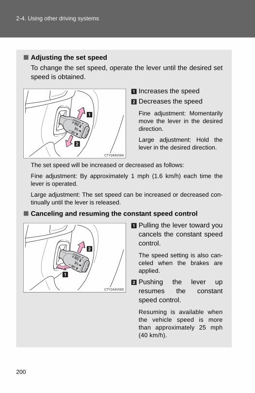
200
2-4. Using other driving systems
■ Adjusting the set speedTo change the set speed, operate the lever until the desired setspeed is obtained.
Increases the speedDecreases the speed
Fine adjustment: Momentarilymove the lever in the desireddirection.
Large adjustment: Hold thelever in the desired direction.
The set speed will be increased or decreased as follows:
Fine adjustment: By approximately 1 mph (1.6 km/h) each time thelever is operated.
Large adjustment: The set speed can be increased or decreased con-tinually until the lever is released.
■ Canceling and resuming the constant speed controlPulling the lever toward youcancels the constant speedcontrol.
The speed setting is also can-celed when the brakes areapplied.
Pushing the lever upresumes the constantspeed control.
Resuming is available whenthe vehicle speed is morethan approximately 25 mph(40 km/h).

201
2-4. Using other driving systems
2
When driving
■Cruise control can be set when●The shift lever is in the D or range 4 or higher of S has been selected.
●Range 4 or higher has been selected by using the paddle shift.(vehicles with paddle shift switch)
●Vehicle speed is above approximately 25 mph (40 km/h).
■Accelerating after setting the vehicle speed●The vehicle can be accelerated normally. After acceleration, the set
speed resumes.
●Even without canceling the cruise control, the set speed can beincreased by first accelerating the vehicle to the desired speed and thenpushing the lever down to set the new speed.
■Automatic cruise control cancelationCruise control will stop maintaining the vehicle speed in any of the followingsituations.
●Actual vehicle speed falls more than approximately 10 mph (16 km/h)below the preset vehicle speed.At this time, the memorized set speed is not retained.
●Actual vehicle speed is below approximately 25 mph (40 km/h).
●VSC is activated.
■ If the cruise control indicator light comes on in yellowPress the “ON-OFF” button once to deactivate the system, and then pressthe button again to reactivate the system.If the cruise control speed cannot be set or if the cruise control cancelsimmediately after being activated, there may be a malfunction in the cruisecontrol system. Have the vehicle inspected by your Toyota dealer.

202
2-4. Using other driving systems
CAUTION
■To avoid operating the cruise control by mistakeSwitch the cruise control off using the “ON-OFF” button when not in use.
■Situations unsuitable for cruise controlDo not use cruise control in any of the following situations.Doing so may result in loss of control and could cause an accident resultingin death or serious injury.
● In heavy traffic
●On roads with sharp bends
●On winding roads
●On slippery roads, such as those covered with rain, ice or snow
●On steep hillsVehicle speed may exceed the set speed when driving down a steep hill.

203
2-4. Using other driving systems
2
When driving
Driving assist systems
When the TRAC/VSC systems are operating
If the vehicle is in danger of slip-ping or if any of the drive wheelsspins, the slip indicator lightflashes to indicate that the VSC/TRAC systems are operating.
To help enhance driving safety and performance, the following sys-tems operate automatically in response to various driving situations.Be aware, however, that these systems are supplementary andshould not be relied upon too heavily when operating the vehicle.
■ ABS (Anti-lock Brake System)Helps to prevent wheel lock when the brakes are applied suddenly, or ifthe brakes are applied while driving on a slippery road surface.
■ Brake assistGenerates an increased level of braking force after the brake pedal isdepressed when the system detects a panic stop situation.
■ VSC (Vehicle Stability Control)Helps the driver to control skidding when swerving suddenly or turningon slippery road surfaces.
■ TRAC (Traction Control)Helps to maintain drive power and prevent the drive wheels from spin-ning when starting the vehicle or accelerating on slippery roads.
■ EPS (Electric Power Steering) Employs an electric motor to reduce the amount of effort needed to turnthe steering wheel.
■ BSM (Blind Spot Monitor) (if equipped) →P. 208

204
2-4. Using other driving systems
Disabling the TRAC/VSC systems
If the vehicle gets stuck in fresh snow or mud, the TRAC/VSC sys-tems may reduce power from the engine to the wheels. You mayneed to turn the system off to enable you to rock the vehicle in orderto free it.
■ Turning off the TRAC system onlyQuickly push and release theswitch to turn off TRAC.
The “TRAC OFF” indicator lightshould come on.
Press the switch again to turn thesystem back on.
■ Turning off both TRAC and VSC systemsPush and hold the switch formore than 3 seconds while thevehicle is stopped to turn offTRAC and VSC.
The “TRAC OFF” and VSC OFFindicator lights should come on.
Press the switch again to turn thesystems back on.

205
2-4. Using other driving systems
2
When driving
■When the “TRAC OFF” indicator light comes on even if the VSC OFFswitch has not been pressedTRAC cannot be operated. Contact your Toyota dealer.
■Sounds and vibrations caused by the ABS, brake assist, VSC andTRAC●A sound may be heard from the engine compartment when the engine is
started or just after the vehicle begins to move. This sound does not indi-cate that a malfunction has occurred in any of these systems.
●Any of the following conditions may occur when the above systems areoperating. None of these indicates that a malfunction has occurred.
• Vibrations may be felt through the vehicle body and steering.• A motor sound may be heard after the vehicle comes to a stop.• The brake pedal may pulsate slightly after the ABS is activated.• The brake pedal may move down slightly after the ABS is activated.
■EPS operation soundWhen the steering wheel is operated, a motor sound (whirring sound) maybe heard. This does not indicate a malfunction.
■Reactivation of the TRAC /VSC systems after turning off the engineTurning off the engine after turning off the TRAC/VSC systems will automati-cally reactivate them.
■Reactivation of the TRAC system linked to vehicle speedWhen only the TRAC system is turned off, the TRAC system will turn onwhen vehicle speed increases. However, when both TRAC and VSC sys-tems are turned off, the systems will not turn on even when vehicle speedincreases.
■Reduced effectiveness of the EPS systemThe effectiveness of the EPS system is reduced to prevent the system fromoverheating when there is frequent steering input over an extended period oftime. The steering wheel may feel heavy as a result. Should this occur,refrain from excessive steering input or stop the vehicle and turn the engineoff. The EPS system should return to normal within 10 minutes.
■ If the slip indicator comes on...It may indicate a malfunction in the TRAC and VSC. Contact your Toyotadealer.

206
2-4. Using other driving systems
CAUTION
■ABS does not operate effectively when●Tires with inadequate gripping ability are used (such as excessively worn
tires on a snow covered road).
●The vehicle hydroplanes while driving at high speed on the wet or slickroad.
■Stopping distance when the ABS is operating may exceed that of nor-mal conditionsThe ABS is not designed to shorten the vehicle’s stopping distance. Alwaysmaintain a safe distance from the vehicle in front of you in the following situ-ations:
●When driving on dirt, gravel or snow-covered roads
●When driving with tire chains
●When driving over bumps in the road
●When driving over roads with potholes or roads with uneven surfaces
■TRAC may not operate effectively whenDirectional control and power may not be achievable while driving on slip-pery road surfaces, even if the TRAC system is operating.Do not drive the vehicle in conditions where stability and power may be lost.

207
2-4. Using other driving systems
2
When driving
CAUTION
■When the VSC is activatedThe slip indicator light flashes. Always drive carefully. Reckless driving maycause an accident. Exercise particular care when the indicator light flashes.
■When the TRAC/VSC systems are turned offBe especially careful and drive at a speed appropriate to the road condi-tions. As these are the systems to ensure vehicle stability and driving force,do not turn the TRAC/VSC systems off unless necessary.
■Replacing tiresMake sure that all tires are of the specified size, brand, tread pattern andtotal load capacity. In addition, make sure that the tires are inflated to therecommended tire inflation pressure level.
The ABS, TRAC and VSC systems will not function correctly if different tiresare installed on the vehicle.
Contact your Toyota dealer for further information when replacing tires orwheels.
■Handling of tires and suspensionUsing tires with any kind of problem or modifying the suspension will affectthe driving assist systems, and may cause a system to malfunction.

208
2-4. Using other driving systems
BSM (Blind Spot Monitor)∗
∗: If equipped
The Blind Spot Monitor is a system that assists the driver in makingthe decision to change lanes. The system uses radar sensors to detect vehicles that are travelingin an adjacent lane in the area that is not reflected in the outside rearview mirror (the blind spot), and advises the driver of the vehiclesexistence via the outside rear view mirror indicator.
BSM main switchPressing the switch turns the system on or off. When the switch is setto on, the switch’s indicator illuminates.
Outside rear view mirror indicatorWhen a vehicle is detected in the blind spot, the outside rear view mir-ror indicator on that side illuminates. If the turn signal lever is operatedwhen a vehicle is in the blind spot, the outside rear view mirror indicatorflashes.

209
2-4. Using other driving systems
2
When driving
The Blind Spot Monitor detection areas
The blind spot that vehicles can be detected in are outlined below.
The range of the detection areaextends to:
Approximately 11.5 ft. (3.5 m)from the side of the vehicle
The first 1.6 ft. (0.5 m) from theside of the vehicle is not in thedetection area
Approximately 9.8 ft. (3 m)from the rear bumperApproximately 3.3 ft. (1 m) for-ward of the rear bumper
■The Blind Spot Monitor is operational whenThe BSM main switch is set to on and vehicle speed is greater than about 25mph (40 km/h)
■The Blind Spot Monitor will detect a vehicle when●A vehicle in an adjacent lane overtakes your vehicle
●Another vehicle enters the vehicles detection area when it changeslanes.

210
2-4. Using other driving systems
■Conditions under which the Blind Spot Monitor will not detect a vehicleThe Blind Spot Monitor is not designed to detect the following types of vehi-cles and/or objects:
●Vehicles traveling from the opposite direction
●Small motorcycles, bicycles, pedestrians etc.*
●Guardrails, walls, signs, parked vehicles and similar stationary objects*
●Following vehicles that are in the same lane*
●Vehicles driving 2 lanes across from your vehicle*
*: Depending on conditions, detection of a vehicle and/or object may occur
■Conditions under which the Blind Spot Monitor may not function cor-rectly●The Blind Spot Monitor may not detect vehicles correctly in the following
conditions:
• During bad weather such as heavy rain, fog, snow etc.• When ice, mud etc. is attached to the rear bumper• When driving on a road surface that is wet due to rain, standing water
etc.• When there is a significant difference in speed between your vehicle
and the vehicle that enters the detection area• When a vehicle is in the detection area from a stop and remains in the
detection area as your vehicle accelerates• When driving up or down consecutive steep inclines, such as hills, a
dip in the road etc.• When multiple vehicles approach with only a small gap between each
vehicle• When vehicle lanes are wide, and the vehicle in the next lane is too far
away from your vehicle• When the vehicle that enters the detection area is traveling at about
the same speed as your vehicle• When there is a significant difference in height between your vehicle
and the vehicle that enters the detection area.• Directly after the BSM switch is set to on.

211
2-4. Using other driving systems
2
When driving
● Instances of the Blind Spot Monitor unnecessarily detecting a vehicleand/or object may increase under the following conditions:
• When there is only a short distance between your vehicle and a guard-rail, wall etc.
• When there is only a short distance between your vehicle and a follow-ing vehicle.
• When vehicle lanes are narrow and a vehicle driving 2 lanes acrossfrom your vehicle enters the detection area
■The outside rear view mirror indicators visibilityWhen under strong sunlight, the outside rear view mirror indicator may bedifficult to see.
■When there is a malfunction in the systemIf a system malfunction is detected due to any of the following reasons,warning lights will turn on: (→P. 421)
●There is a malfunction with the sensors
●The sensors have become dirty
●The outside temperature is extremely high or low
●The sensor voltage has become abnormal
■Certification for the Blind Spot MonitorFCC ID: OAYBSDTX
This device complies with part 15 of the FCC Rules. Operation is subject tothe following three conditions:
(1) This device may not cause harmful interference.
(2) This device must accept any interference received, including interferencethat may cause undesired operation.
(3) This device may only work when the vehicle is in operation pursuant to§ 15.252 (a) (4).
FCC WARNING
Changes or modifications not expressly approved by the party responsiblefor compliance could void the user’s authority to operate the equipment.

212
2-4. Using other driving systems
CAUTION
■Cautions regarding the use of the systemThe driver is solely responsible for safe driving. Always drive safely, takingcare to observe your surroundings.The Blind Spot Monitor is a supplementary system which alerts the driverthat a vehicle is present in the blind spot. Do not overly rely on the Blind SpotMonitor. The system cannot judge if it is safe to change lanes, therefore overreliance could cause an accident resulting in death or serious injury. Accord-ing to conditions, the system may not function correctly. Therefore thedriver’s own visual confirmation of safety is necessary.
■Handling the radar sensorOne Blind Spot Monitor is installed inside the left and right side of the vehiclerear bumper respectively. Observe the following to ensure the Blind SpotMonitor can function correctly.
●Do not subject the sensor or surrounding area on the bumper to a strongimpact. If the sensor moves even slightly off position, the system may mal-function and vehicles that enter the detection area may not be detected. Ifthe sensor or surrounding area is subject to a strong impact, always havethe area inspected by your Toyota dealer.
●Do not disassemble the sensor.
●Do not attach accessories or stickers to the sensor or surrounding area onthe bumper.
●Do not modify the sensor or surrounding area on the bumper.
●Do not paint the sensor or surrounding area on the bumper.
●Keep the sensor and its surroundingarea on the bumper clean at all times.

213
2
When driving
2-5. Driving information
Cargo and luggage
Capacity and distribution
Cargo capacity depends on the total weight of the occupants.
(Cargo capacity) = (Total load capacity) - (Total weight of occupants)
Steps for Determining Correct Load Limit⎯(1)Locate the statement “The combined weight of occupants and
cargo should never exceed XXX kg or XXX lbs.” on your vehicle'splacard.
(2)Determine the combined weight of the driver and passengers thatwill be riding in your vehicle.
(3)Subtract the combined weight of the driver and passengers fromXXX kg or XXX lbs.
(4)The resulting figure equals the available amount of cargo and lug-gage load capacity. For example, if the “XXX” amount equals 1400 lbs. and there willbe five 150 lb passengers in your vehicle, the amount of availablecargo and luggage load capacity is 650 lbs. (1400 - 750 (5 × 150) =650 lbs.)
(5)Determine the combined weight of luggage and cargo beingloaded on the vehicle. That weight may not safely exceed the avail-able cargo and luggage load capacity calculated in Step 4.
Take notice of the following information about storage precau-tions, cargo capacity and load:
● Stow cargo and luggage in the trunk whenever possible.
● Be sure all items are secured in place.
● To maintain vehicle balance while driving, position luggageevenly within the luggage compartment.
● For better fuel economy, do not carry unnecessary weight.

214
2-5. Driving information
(6)If your vehicle will be towing a trailer, load from your trailer will betransferred to your vehicle. Consult this manual to determine howthis reduces the available cargo and luggage load capacity of yourvehicle.(→P. 466)Toyota does not recommend towing a trailer with your vehicle. Yourvehicle is not designed for trailer towing.
Example based on your vehicle
Cargo capacityTotal load capacity
When 2 people with the combined weight of 366 lb. (166 kg) areriding in your vehicle, which has a total load capacity of 905 lb. (410kg), the available amount of cargo and luggage load capacity will beas follows:
905 lb. - 366 lb. = 539 lb. (410 kg -166 kg = 244 kg)
In this condition, if 3 more passengers with the combined weight of388 lb. (176 kg) get on, the available cargo and luggage load will bereduced as follows:
539 lb. - 388 lb. = 151 lb. (244 kg - 176 kg = 68 kg)
As shown in the above example, if the number of occupantsincreases, the cargo and luggage load will be reduced by an amountthat equals the increased weight due to the additional occupants. Inother words, if an increase in the number of occupants causes anexcess of the total load capacity (combined weight of occupants pluscargo and luggage load), you must reduce the cargo and luggage onyour vehicle.

215
2-5. Driving information
2
When driving
CAUTION
■Things that must not be carried in the trunkThe following things may cause a fire if loaded in the trunk:●Receptacles containing gasoline●Aerosol cans
■Storage precautionsObserve the following precautions. Failure to do so may result in death or serious injury.●Stow cargo and luggage in the trunk whenever possible.●To prevent cargo and luggage from sliding forward during braking, do
not stack anything in the enlarged trunk. Keep cargo and luggage low,as close to the floor as possible.
●When you fold down the rear seats, long items should not be placeddirectly behind the front seats.
●Never allow anyone to ride in the enlarged trunk. It is not designed forpassengers. They should ride in their seats with their seat belts prop-erly fastened. Otherwise, they are much more likely to suffer death orserious bodily injury, in the event of sudden braking, sudden swervingor an accident.
●Do not place cargo or luggage in or on the following locations as theitem may get under the brake or accelerator pedal and prevent thepedals from being depressed properly, block the driver’s vision, or hitthe driver or passengers, causing an accident:• At the feet of the driver• On the front passenger or rear seats (when stacking items)• On the package tray• On the instrument panel• On the dashboard
●Secure all items in the occupant compartment, as they may shift andinjure someone during sudden braking, sudden swerving or an acci-dent.

216
2-5. Driving information
CAUTION
■Capacity and distribution●Do not exceed the maximum axle weight rating or the total vehicle
weight rating. ●Even if the total load of occupant's weight and the cargo load is less
than the total load capacity, do not apply the load unevenly. Improper loading may cause deterioration of steering or braking con-trol which may cause death or serious injury.

217
2-5. Driving information
2
When driving
Vehicle load limits
■Total load capacity and seating capacityThese details are also described on the tire and loading informationlabel. (→P. 375)
CAUTION
■Overloading the vehicleDo not overload the vehicle.It may not only cause damage to the tires, but also degrade steering andbraking ability, resulting in an accident.
Vehicle load limits include total load capacity, seating capacity,towing capacity and cargo capacity.
■ Total load capacity: 905 lb. (410 kg) Total load capacity means the combined weight of occupants, cargoand luggage.
■ Seating capacity: 5 occupants (Front 2, Rear 3)Seating capacity means the maximum number of occupants whoseestimated average weight is 150 lb. (68 kg) per person.
■ Towing capacityToyota does not recommend towing a trailer with your vehicle.
■ Cargo capacityCargo capacity may increase or decrease depending on the weightand the number of occupants.

218
2-5. Driving information
Winter driving tips
Carry out the necessary preparations and inspections before drivingthe vehicle in winter. Always drive the vehicle in a manner appropri-ate to the prevailing weather conditions.
■ Pre-winter preparations● Use fluids that are appropriate to the prevailing outside tem-
peratures.
• Engine oil• Engine coolant• Washer fluid
● Have a service technician inspect the level and specific grav-ity of battery electrolyte.
● Have the vehicle fitted with four snow tires or purchase a setof tire chains for the front tires.
Ensure that all tires are the same size and brand, and that chainsmatch the size of the tires.
■ Before driving the vehiclePerform the following according to the driving conditions:
● Do not try to forcibly open a window or move a wiper that isfrozen. Pour warm water over the frozen area to melt the ice.Wipe away the water immediately to prevent it from freezing.
● To ensure proper operation of the climate control system fan,remove any snow that has accumulated on the air inlet ventsin front of the windshield.
● Remove any ice that has accumulated on the vehicle chassis.
● Periodically check for and remove any excess ice or snowthat may have accumulated in the wheel well or on thebrakes.

219
2-5. Driving information
2
When driving
Selecting tire chains
Use the correct tire chain size when mounting the snow chains. Chain size is regulated for each tire size.
Side chain: 0.12 in. (3 mm) in diameter 0.39 in. (10 mm) in width 1.18 in. (30 mm) in length
Cross chain: 0.16 in. (4 mm) in diameter 0.55 in. (14 mm) in width 0.98 in. (25 mm) in length
Regulations on the use of tire chains
Regulations regarding the use of tire chains vary according to loca-tion and type of road. Always check local regulations before installingchains.
■ When driving the vehicleAccelerate the vehicle slowly and drive at a reduced speed suit-able to road conditions.
■ When parking the vehiclePark the vehicle and move the shift lever to P without setting theparking brake. The parking brake may freeze up, preventing itfrom being released. If necessary, block the wheels to preventinadvertent sliding or creeping.

220
2-5. Driving information
■Tire chain installationObserve the following precautions when installing and removing chains:
● Install and remove tire chains in a safe location.
● Install tire chains on the front tires only. Do not install tire chains on therear tires.
● Install tire chains on front tires as tightly as possible. Retighten chainsafter driving 1/4 ⎯ 1/2 mile (0.5 ⎯ 1.0 km).
● Install tire chains following the instructions provided with the tire chains.
CAUTION
■Driving with snow tiresObserve the following precautions to reduce the risk of accidents.Failure to do so may result in a loss of vehicle control and cause death orserious injury.
●Use tires of the size specified.
●Maintain the recommended level of air pressure.
●Do not drive in excess of 75 mph (120 km/h), regardless of the type ofsnow tires being used.
●Use snow tires on all, not just some wheels.
■Driving with tire chainsObserve the following precautions to reduce the risk of accidents.Failure to do so may result in the vehicle being unable to be driven safely,and may cause death or serious injury.
●Do not drive in excess of the speed limit specified for the tire chains beingused, or 30 mph (50 km/h), whichever is lower.
●Avoid driving on bumpy road surfaces or over potholes.
●Avoid sudden turns and braking, as use of chains may adversely affectvehicle handling.
●Slow down sufficiently before entering a curve to ensure that vehicle con-trol is maintained.

221
2-5. Driving information
2
When driving
NOTICE
■Repairing or replacing snow tiresRequest repairs or replacement of snow tires from Toyota dealers or legiti-mate tire retailers.This is because the removal and attachment of snow tires affects the opera-tion of the tire pressure warning valves and transmitters.
■Fitting tire chainsThe tire pressure warning valves and transmitters may not function correctlywhen tire chains are fitted.

222
2-5. Driving information
Trailer towing
Toyota does not recommend towing a trailer with your vehicle.Toyota also does not recommend the installation of a tow hitch orthe use of a tow hitch carrier for a wheelchair, scooter, bicycle, etc.Your vehicle is not designed for trailer towing or for the use of towhitch mounted carriers.

223
2-5. Driving information
2
When driving
Dinghy towing
NOTICE
■To avoid serious damage to your vehicleDo not tow your vehicle with the four wheels on the ground.
Your vehicle is not designed to be dinghy towed (with 4 wheels onthe ground) behind a motor home.

224
2-5. Driving information

226
3-1. Using the air conditioning system and defogger
Manual air conditioning system∗
∗: If equipped
Fan speed control dial
Air outlet selection button
Air intake mode button Cooling and dehumidification function on/off button
Temperature control dial
Windshield defogger

227
3-1. Using the air conditioning system and defogger
3
Interior features
Adjusting the settings
To adjust the fan speed, turn the fan speed control dial clock-wise (increase) or counterclockwise (decrease).Turning the dial to “OFF” turns off the fan.
To adjust the temperature setting, turn the temperature controldial clockwise (warm) or counterclockwise (cool).
If is not pressed, the system will blow ambient temperature
air or heated air.
For quick cooling, turn the temperature control dial to “MAX A/C”.The air conditioning will automatically turn on. The air intake mode
button will be set for recirculated air mode when or isselected. It is not possible to turn to the outside air mode.
To change the air outlets, press , , or
.
Defogging the windshield
Press .
If the recirculated air mode isused, it will automatically switchto the outside air mode.
STEP 1
STEP 2
STEP 3
STEP 1

228
3-1. Using the air conditioning system and defogger
Perform the following operations accordingly:● To adjust the fan speed, turn the fan speed control dial.
● To adjust the temperature setting, turn the temperature con-trol dial.
● If the dehumidification function is not operating, press
to operate the dehumidification function.
To defog the windshield and the side windows early, turn theair flow and temperature up.
Air outlets and air flow
Air flows to the upper body.
Air flows to the upper body andfeet.
STEP 2

229
3-1. Using the air conditioning system and defogger
3
Interior features
Air flows to the feet.
The air intake is automaticallyswitched to outside air mode.
Air flows to the feet and thewindshield defogger operates.
Switching between outside air and recirculated air modes
Press .
The mode switches between outside air mode (introduces air from out-side the vehicle) (indicator off) and recirculated air mode (recycles airinside the vehicle) (indicator on) each time the button is pressed.

230
3-1. Using the air conditioning system and defogger
Adjusting the position of and opening and closing the air outlets
Front center outletsDirect air flow to the left or right,up or down.
Front side outletsDirect air flow to the left orright, up or down.Turn the knob to open or closethe vent.

231
3-1. Using the air conditioning system and defogger
3
Interior features
■Switching between outside air and recirculated air modesRecirculated air mode or outside air mode may be automatically switched toin accordance with the temperature setting and the inside temperature.
■Fogging up of the windows●The windows will easily fog up when the humidity in the vehicle is high.
Turning on will dehumidify the air from the outlets and defog the
windshield effectively.
● If you turn off, the windows may fog up more easily.
●The windows may fog up if the recirculated air mode is used.
■Outside/recirculated air modeWhen driving on dusty roads such as tunnels or in heavy traffic, set the out-side/recirculated air mode button to the recirculated air mode. This is effec-tive in preventing outside air from entering the vehicle interior. During coolingoperation, setting the recirculated air mode will also cool the vehicle interioreffectively.
■When the outside temperature falls to nearly 32°F (0°C)
The dehumidification function may not operate even when is
pressed.
■Air conditioning odors●During use, various odors from inside and outside the vehicle may enter
into and accumulate in the air conditioning system. This may then causeodor to be emitted from the vents.
●To reduce potential odors from occurring:It is recommended that the air conditioning system be set to outside airmode prior to turning the vehicle off.
■Air conditioning filter→P. 382

232
3-1. Using the air conditioning system and defogger
CAUTION
■To prevent the windshield from fogging up
Do not use during cool air operation in extremely humid weather.
The difference between the temperature of the outside air and that of thewindshield can cause the outer surface of the windshield to fog up, blockingyour vision.
NOTICE
■To prevent battery dischargeDo not leave the air conditioning system on longer than necessary when theengine is stopped.

233
3-1. Using the air conditioning system and defogger
3
Interior features
Automatic air conditioning system∗
∗: If equipped
Air outlets and fan speed are automatically adjusted according to thetemperature setting.
Cooling and dehumidification function on/off button
Front passenger’s side temperature setting displayDriver’s side
temperature control
“DUAL” button
Automatic mode
Off
Driver’s side temperature setting display
Fan speed
Outside air or recirculated air mode
Fan speed display
Change the air outlets used
Front passenger’s side temperature control
Windshield defogger
Air outlet display

234
3-1. Using the air conditioning system and defogger
Using the automatic air conditioning system
Press .
The air conditioning system begins to operate. Air outlets andfan speed are automatically adjusted according to the temper-ature setting.
Turn clockwise to increase the temperature and turn
counterclockwise to decrease the temperature.
When is pressed (the indicator is on) or the passen-ger’s side temperature control dial is turned, the temperature for thedriver and passenger seats can be adjusted separately.
Adjusting the settings manually
To adjust the fan speed, press “>” on to increase thefan speed and “<” to decrease the fan speed.Press to turn the fan off.
To adjust the temperature setting, turn clockwise to
increase the temperature and turn counterclockwise to
decrease the temperature.
When is pressed (the indicator is on) or the passen-ger’s side temperature control dial is turned, the temperature for thedriver and passenger seats can be adjusted separately.
To change the air outlets, press “<” or “>” on .
The air outlets used are switched each time either side of the buttonis pressed.
STEP 1
STEP 2
STEP 1
STEP 2
STEP 3

235
3-1. Using the air conditioning system and defogger
3
Interior features
Defogging the windshield
Press .
The dehumidification functionoperates and fan speedincreases.Set the outside/recirculated airmode button to the outside airmode if the recirculated air modeis used. (It may switch automati-cally.)To defog the windshield and theside windows early, turn the airflow and temperature up.To return to the previous mode,
press again when thewindshield is defogged.
Air outlets and air flow
Air flows to the upper body.

236
3-1. Using the air conditioning system and defogger
Air flows to the upper body andfeet.
Air flows to the feet.
*: When the warming function isoperating, air flows to theupper body as well to warm theupper body effectively.
Air flows to the feet and thewindshield defogger operates.
Switching between outside air and recirculated air modes
Press .
The mode switches between outside air mode (the indicator is off) andrecirculated air mode (the indicator is on) each time the button ispressed.
*
*

237
3-1. Using the air conditioning system and defogger
3
Interior features
Adjusting the position of and opening and closing the air outlets
Front center outletsDirect air flow to the left or right,up or down.
Front side outletsDirect air flow to the left orright, up or down.Turn the knob to open or closethe vent.
Rear outletsDirect air flow to the left orright, up or down.Turn the knob to open or closethe vent.

238
3-1. Using the air conditioning system and defogger
■Using automatic modeFan speed is adjusted automatically according to the temperature settingand the ambient conditions.
Therefore, the fan may stop for a while until warm or cool air is ready to flow
immediately after is pressed.
■Fogging up of the windows●The windows will easily fog up when the humidity in the vehicle is high.
Turning on will dehumidify the air from the outlets and defog thewindshield effectively.
● If you turn off, the windows may fog up more easily.
●The windows may fog up if the recirculated air mode is used.
■Outside/recirculated air mode●When driving on dusty roads such as tunnels or in heavy traffic, set the
outside/recirculated air mode button to the recirculated air mode. This iseffective in preventing outside air from entering the vehicle interior. Dur-ing cooling operation, setting the recirculated air mode will also cool thevehicle interior effectively.
●Outside/recirculated air mode may automatically switch depending onthe temperature setting or the inside temperature.
■When the outside temperature falls to nearly 32°F (0°C)
The dehumidification function may not operate even when ispressed.

239
3-1. Using the air conditioning system and defogger
3
Interior features
■Air conditioning odors●During use, various odors from inside and outside the vehicle may enter
into and accumulate in the air conditioning system. This may then causeodor to be emitted from the vents.
●To reduce potential odors from occurring:
• It is recommended that the air conditioning system be set to outside airmode prior to turning the vehicle off.
• The start timing of the blower may be delayed for a short period of timeimmediately after the air conditioning system is started in automaticmode.
■Air conditioning filter→P. 382
■Customization that can be configured at Toyota dealerSettings (e.g. air conditioning setting) can be changed. (Customizable features →P. 493)
CAUTION
■To prevent the windshield from fogging up
Do not use during cool air operation in extremely humid weather.The difference between the temperature of the outside air and that of thewindshield can cause the outer surface of the windshield to fog up, blockingyour vision.
NOTICE
■To prevent battery dischargeDo not leave the air conditioning system on longer than necessary when theengine is stopped.

240
3-1. Using the air conditioning system and defogger
Rear window and outside rear view mirror defoggers
■The defoggers can be operated whenVehicles without a smart key systemThe engine switch is in the “ON” position.
Vehicles with a smart key systemThe “ENGINE START STOP” switch is in IGNITION ON mode.
■The outside rear view mirror defoggers (if equipped)Turning the rear window defogger on will turn the outside rear view mirrordefoggers on.
Defoggers are used to defog the rear window, and to remove rain-drops, dew and frost from the outside rear view mirrors.
Vehicles with a manual air conditioning systemTurns the defoggers on/off
The defoggers will automati-cally turn off after their opera-tion time. The operation time isbetween 15 minutes and 1hour depending on the ambienttemperature and vehiclespeed.
Vehicles without outside rear view mirror defoggersVehicles with outside rear view mirror defoggers
Vehicles with an automatic air conditioning systemTurns the defoggers on/off
The defoggers will automati-cally turn off after their opera-tion time. The operation time isbetween 15 minutes and 1hour depending on the ambienttemperature and vehiclespeed.
A
B

241
3-1. Using the air conditioning system and defogger
3
Interior features
CAUTION
■When the outside rear view mirror defoggers are on (if equipped)Do not touch the outside surface of the rear view mirrors, as they canbecome very hot and burn you.

242
3-2. Using the audio system
Audio system types
Without navigation system and Display Audio systemCD player and AM/FM radio
Title Page
Using the radio P. 248
Using the CD player P. 251
Playing back MP3 and WMA discs P. 257
Operating an iPod P. 264
Operating a USB memory P. 272
Optimal use of the audio system P. 280
Using the AUX port P. 283

243
3-2. Using the audio system
3
Interior features
With Display Audio systemOwners of models equipped with a Display Audio system shouldrefer to the “Display Audio System Owner's Manual”.
Display Audio systemPremium Display Audio system
With navigation systemOwners of models equipped with a navigation system should referto the “Navigation System Owner's Manual”.
A
B

244
3-2. Using the audio system
■About Bluetooth® (with Display Audio system)The Bluetooth wordmark and logo are owned by Bluetooth SIG. and permis-sion has been granted to use the trademark of the licensee Panasonic Cor-poration/Pioneer Corporation. Other trademarks and trade names areowned by various different owners.
CAUTION
■Certifications for the Bluetooth® (with Display Audio system)FCC ID: ACJ932CQ-US70G0IC ID: 216J-CQUS70G0
FCC ID: AJDK032IC ID: 775E-K032
●FCC WARNING:
Changes or modifications not expressly approved by the party responsiblefor compliance could void the user's authority to operate the equipment.
●Part 15 of the FCC Rules & Industry Canada licence-exempt RSS stan-dard(s)
• Properly shielded a grounded cables and connectors must be used forconnection to host computer and/or peripherals in order to meet FCCemission limits.
• This transmitter must not be co-located or operated in conjunction withany other antenna or transmitter.
• This device complies with Part 15 of FCC Rules and Industry Canadalicence-exempt RSS standard(s). Operation is subject to the followingtwo conditions: (1) this device may not cause interference, and (2) thisdevice must accept any interference, including interference that maycause undesired operation of this device.
• Le présent appareil est conforme aux la partie 15 des règles de la FCCet CNR d’Industrie Canada applicables aux appareils radio exempts delicence. L’exploitation est autorisée aux deux conditions suivantes : (1)l’appareil ne doit pas produire de brouillage, et (2) l’utilisateur del’appareil doit accepter tout brouillage radioélectrique subi, même si lebrouillage est susceptible d’en compromettre le fonctionnement.

245
3-2. Using the audio system
3
Interior features
CAUTION
• This equipment complies with FCC/IC radiation exposure limits setforth for an uncontrolled environment and meets the FCC radio fre-quency (RF) Exposure Guidelines in Supplement C to OET65 andRSS-102 of the IC radio frequency (RF) Exposure rules. This equip-ment has very low levels of RF energy that it deemed to comply withoutmaximum permissive exposure evaluation (MPE). But it is desirablethat it should be installed and operated keeping the radiator at least 20cm or more away from person’s body (excluding extremities: hands,wrists, feet and ankles).
• Cet équipement est conforme aux limites d’exposition auxrayonnements énoncées pour un environnement non contrôlé etrespecte les règles les radioélectriques (RF) de la FCC lignesdirectrices d’exposition dans le Supplément C à OET65 et d’expositionaux fréquences radioélectriques (RF) CNR-102 de l’IC. Cetéquipement émet une énergie RF très faible qui est considéréeconforme sans évaluation de l’exposition maximale autorisée. Cependant, cet équipement doit être installé et utilisé en gardant unedistance de 20 cm ou plus entre le dispositif rayonnant et le corps (àl’exception des extrémités : mains, poignets, pieds et chevilles).
• Under Industry Canada regulations, this radio transmitter may onlyoperate using an antenna of a type and maximum (or lesser) gainapproved for the transmitter by Industry Canada. To reduce potentialradio interference to other users, the antenna type and its gain shouldbe so chosen that the equivalent isotropically radiated power (e.i.r.p.) isnot more than that necessary for successful communication.
• Conformément à la réglementation d’Industrie Canada, le présentémetteur radio peut fonctionner avec une antenne d’un type et d’ungain maximal (ou inférieur) approuvé pour l’émetteur par IndustrieCanada. Dans le but de réduire les risques de brouillageradioélectrique à l’intention des autres utilisateurs, il faut choisir le typed’antenne et son gain de sorte que la puissance isotrope rayonnéeéquivalente (p.i.r.e.) ne dépasse pas l’intensité nécessaire àl’établissement d’une communication satisfaisante.

246
3-2. Using the audio system
CAUTION
●Laser products
• Do not take this unit apart or attempt to make any changes yourself. This is an intricate unit that uses a laser pickup to retrieve informationfrom the surface of compact discs. The laser is carefully shielded sothat its rays remain inside the cabinet. Therefore, never try to disas-semble the player or alter any of its parts since you may be exposed tolaser rays and dangerous voltages.
• This product utilizes a laser.Use of controls or adjustments or performance of procedures otherthan those specified herein may result in hazardous radiation expo-sure.THE USE OF OPTICAL INSTRUMENTS WITH THIS PRODUCT WILLINCREASE EYE HAZARD.

247
3-2. Using the audio system
3
Interior features
NOTICE
■To prevent battery dischargeDo not leave the audio system on longer than necessary when the engine isstopped.
■To avoid damaging the audio systemTake care not to spill drinks or other fluids over the audio system.

248
3-2. Using the audio system
Using the radio
Setting station presets
Search for a desired station by turning or pressing
or .
Press and hold a button (from to ) until you hear
a beep.
VolumePreset station selector
Seeking the frequency
Adjusting the frequency
AM/FM mode button
Power
Displayingradio text messages
Scanning for receivable stations
STEP 1
STEP 2

249
3-2. Using the audio system
3
Interior features
Scanning radio stations
■ Scanning the preset radio stations
Press and hold until you hear a beep.
Preset stations will be played for 5 seconds each.
When the desired station is reached, press once
again.
■ Scanning all radio stations within range
Press .
All stations with reception will be played for 5 seconds each.
When the desired station is reached, press once
again.
Switching the display
Press .
Each time is pressed, the display changes in the following order:
Frequency → Channel name → Radio text.
STEP 1
STEP 2
STEP 1
STEP 2

250
3-2. Using the audio system
■Reception sensitivity●Maintaining perfect radio reception at all times is difficult due to the con-
tinually changing position of the antenna, differences in signal strengthand surrounding objects, such as trains, transmitters, etc.
●The radio antenna is mounted inside the rear window. To maintain clearradio reception, do not attach metallic window tinting or other metallicobjects to the antenna wire mounted inside the rear window.
■Certifications for the radio tunerThis equipment has been tested and found to comply with the limits for aclass B digital device, pursuant to Part 15 of the FCC Rules. These limits aredesigned to provide reasonable protection against harmful interference in aresidential installation. This equipment generates, uses and can radiateradio frequency energy and, if not installed and used in accordance with theinstructions, may cause harmful interference to radio communications. How-ever, there is no guarantee that interference will not occur in a particularinstallation.
If this equipment does cause harmful interference to radio or televisionreception, which can be determined by turning the equipment off and on, theuser is encouraged to try to correct the interference by trying one or more ofthe following:
●Reorienting or relocating the receiving antenna.
● Increasing the separation between the equipment and receiver.
●Connecting the equipment into an outlet on a circuit different from that towhich the receiver is connected.
●Consulting the dealer or an experienced radio/TV technician for help.

251
3-2. Using the audio system
3
Interior features
Using the CD player
Loading CDs
Insert a CD.
Ejecting CDs
Press and remove the CD.
Selecting a track
Turn or press to move up or to move down until
the desired track number is displayed.
Volume
Random playback
Selecting a track, fast-forwarding or reversing
Repeat playPower
CD eject
Selecting a track/displaying track list
Back button
Displaying text messages
Searching playback
Playback/pause

252
3-2. Using the audio system
Selecting a track from a track list
Press .
The track list will be displayed.
Turn and press to select a track.
To return to the previous display, press ( ).
Scanning tracks
Press .
The first 10 seconds of each track will be played.
To cancel, press again.
Press again when the desired track is reached.
Fast-forwarding and reversing tracks
Press and hold or .
Repeat play
Press (RPT).
The current track is played repeatedly until (RPT) is pressedagain.
STEP 1
STEP 2
STEP 1
STEP 2

253
3-2. Using the audio system
3
Interior features
Random playback
Press (RDM).
Tracks are played in a random order until (RDM) is pressed again.
Playing and pausing tracks
Press ( ).
Switching the display
Press .
Each time is pressed, the display changes in the following order:
Track no./Elapsed time → CD title → Track title → Artist name.
■DisplayUp to 12 characters can be displayed at a time.
If there are 13 characters or more, pressing and holding for 1 sec-
ond or more will display the remaining characters.A maximum of 24 characters can be displayed.
If is pressed for 1 second or more again or has not been pressed for
6 seconds or more, the display will return to the first 12 characters.
Depending on the contents recorded, the characters may not be displayedproperly or may not be displayed at all.

254
3-2. Using the audio system
■Error messages“ERROR”: This indicates a problem either in the CD or inside the player.
“CD CHECK”: The CD may be dirty, damaged or inserted up-side down.
“WAIT”: Operation has stopped due to a high temperature inside theplayer. Contact your Toyota dealer if the CD still cannot beplayed.
■Discs that can be usedDiscs with the marks shown below can be used.Playback may not be possible depending on recording format or disc fea-tures, or due to scratches, dirt or deterioration.
CDs with copy-protect features may not be used.
■CD player protection featureTo protect the internal components, playback is automatically stopped whena problem is detected while the CD player is being used.
■ If a CD is left inside the CD player or in the ejected position forextended periodsThe CD may be damaged and may not play properly.
■Lens cleanersDo not use lens cleaners. Doing so may damage the CD player.

255
3-2. Using the audio system
3
Interior features
NOTICE
■CDs and adapters that cannot be usedDo not use the following types of CDs or 3 in. (8 cm) CD adapters or DualDisc.Doing so may damage the CD player and/or the CD insert/eject function.
●CDs that have a diameter that is not 4.7in. (12 cm)
●Low-quality and deformed CDs
●CDs with a transparent or translucentrecording area
●CDs that have had tape, stickers or CD-R labels attached to them, or that havehad the label peeled off

256
3-2. Using the audio system
NOTICE
■CD player precautionsFailure to follow the precautions below may result in serious damage to theCDs or the player itself.
●Do not insert anything other than CDs into the CD slot.
●Do not apply oil to the CD player.
●Store CDs away from direct sunlight.
●Never try to disassemble any part of the CD player.

257
3-2. Using the audio system
3
Interior features
Playing back MP3 and WMA discs
Loading and ejecting MP3 and WMA discs
→P. 251
Selecting and scanning a folder
■ Selecting a folder
Press or to select the desired folder.
■ Returning to the first file of the first folder
Press and hold until you hear a beep.
Volume
Random playback
Selecting a file, fast-forwarding or reversing
Repeat playPower
CD eject
Selecting a file/displaying folder lists
Back button
Selecting a folder
Displaying text messages
Searchingplayback
Playback/pause

258
3-2. Using the audio system
■ Scanning the first file of all the folders
Press and hold until you hear a beep.
The first 10 seconds of the first file in each folder will be played.
When the desired folder is reached, press again.
■ Selecting a folder and file from folder lists
Press .
The folder list will be displayed.
Turn and press to select a folder and a file.
To return to the previous display, press ( ).
Selecting and scanning files
■ Selecting a file
Turn or press or to select the desired file.
■ Scanning the files in a folder
Press .
The first 10 seconds of each file will be played.
When the desired file is reached, press again.
STEP 1
STEP 2
STEP 1
STEP 2
STEP 1
STEP 2

259
3-2. Using the audio system
3
Interior features
Fast-forwarding and reversing files
Press and hold or .
Repeat play
Pressing (RPT) changes modes in the following order:
File repeat → Folder repeat* → Off.
*: Available except when RDM (random playback) is selected
Random playback
Pressing (RDM) changes modes in the following order:
Folder random → Disc random → Off.
Playing and pausing files
Press ( ).
Switching the display
Press .
Each time is pressed, the display changes in the following order:
Track no./Elapsed time → Folder name → File name → Album title (MP3only) → Track title → Artist name.

260
3-2. Using the audio system
■Display→P. 253
■Canceling random and repeat playback
Press (RPT) or (RDM), or press and hold .
■Error messages“ERROR”: This indicates a problem either in the CD or inside the
player.
“CD CHECK”: The CD may be dirty, damaged or inserted up-side down.
“WAIT”: Operation has stopped due to a high temperature insidethe player. Contact your Toyota dealer if the CD still cannotbe played.
“NO SUPPORT”: This indicates that MP3/WMA files are not included in theCD.
■Discs that can be usedDiscs with the marks shown below can be used.Playback may not be possible depending on recording format or disc fea-tures, or due to scratches, dirt or deterioration.
■CD player protection featureTo protect the internal components, playback is automatically stopped whena problem is detected while the CD player is being used.
■ If a CD is left inside the CD player or in the ejected position forextended periodsThe CD may be damaged and may not play properly.

261
3-2. Using the audio system
3
Interior features
■Lens cleanersDo not use lens cleaners. Doing so may damage the CD player.
■MP3 and WMA filesMP3 (MPEG Audio LAYER3) is a standard audio compression format.
Files can be compressed to approximately 1/10 of their original size by usingMP3 compression.
WMA (Windows Media Audio) is a Microsoft audio compression format.
This format compresses audio data to a size smaller than that of the MP3format.
There is a limit to the MP3 and WMA file standards and to the media/formatsrecorded by them that can be used.
●MP3 file compatibility
• Compatible standardsMP3 (MPEG1 LAYER3, MPEG2 LSF LAYER3)
• Compatible sampling frequenciesMPEG1 LAYER3: 32, 44.1, 48 (kHz)MPEG2 LSF LAYER3: 16, 22.05, 24 (kHz)
• Compatible bit ratesMPEG1 LAYER3: 32, 40, 48, 56, 64, 80, 96, 112, 128, 160, 192, 224,256, 320 (kbps)MPEG2 LSF LAYER3: 8, 16, 24, 32, 40, 48, 56, 64, 80, 96, 112, 128,144, 160 (kbps)* Compatible with VBR
• Compatible channel modes: stereo, joint stereo, dual channel andmonaural
●WMA file compatibility
• Compatible standardsWMA Ver. 7, 8, 9
• Compatible sampling frequencies32, 44.1, 48 (kHz)
• Compatible bit ratesVer. 7, 8: CBR 48, 64, 80, 96, 128, 160, 192 (kbps)Ver. 9: CBR 48, 64, 80, 96, 128, 160, 192, 256, 320 (kbps)* Only compatible with 2-channel playback

262
3-2. Using the audio system
●Compatible media
Media that can be used for MP3 and WMA playback are CD-Rs and CD-RWs.
Playback in some instances may not be possible, depending on the statusof the CD-R or CD-RW. Playback may not be possible or the audio mayjump if the disc is scratched or marked with fingerprints.
●Compatible disc formats
The following disc formats can be used.
• Disc formats: CD-ROM Mode 1 and Mode 2CD-ROM XA Mode 2, Form 1 and Form 2
• File formats: ISO9660 Level 1, Level 2, (Romeo, Joliet)MP3 and WMA files written in any format other than those listed abovemay not play correctly, and their file names and folder names may notbe displayed correctly.
Items related to standards and limitations are as follows.
• Maximum directory hierarchy: 8 levels• Maximum length of folder names/file names: 32 characters• Maximum number of folders: 192 (including the root)• Maximum number of files per disc: 255
●File names
The only files that can be recognized as MP3/WMA and played are thosewith the extension .mp3 or .wma.
●Multi-sessions
As the audio system is compatible with multi-sessions, it is possible to playdiscs that contain MP3 and WMA files. However, only the first session canbe played.
● ID3 and WMA tags
ID3 tags can be added to MP3 files, making it possible to record the tracktitle, artist name, etc.
The system is compatible with ID3 Ver. 1.0, 1.1, and Ver. 2.2, 2.3 ID3 tags.(The number of characters is based on ID3 Ver. 1.0 and 1.1.)
WMA tags can be added to WMA files, making it possible to record thetrack title and artist name in the same way as with ID3 tags.

263
3-2. Using the audio system
3
Interior features
●MP3 and WMA playback
When a disc containing MP3 or WMA files is inserted, all files on the discare first checked. Once the file check is finished, the first MP3 or WMA fileis played. To make the file check finish more quickly, we recommend youdo not write in any files other than MP3 or WMA files or create any unnec-essary folders.
If the discs contain a mixture of music data and MP3 or WMA format data,only music data can be played.
●Extensions
If the file extensions .mp3 and .wma are used for files other than MP3 andWMA files, they will be mistakenly recognized and played as MP3 andWMA files. This may result in large amounts of interference and damageto the speakers.
●Playback
• To play MP3 files with steady sound quality, we recommend a fixed bitrate of 128 kbps and a sampling frequency of 44.1 kHz.
• CD-R or CD-RW playback may not be possible in some instances,depending on the characteristics of the disc.
• There is a wide variety of freeware and other encoding software forMP3 and WMA files on the market, and depending on the status of theencoding and the file format, poor sound quality or noise at the start ofplayback may result. In some cases, playback may not be possible atall.
• When files other than MP3 or WMA files are recorded on a disc, it maytake more time to recognize the disc and in some cases, playback maynot be possible at all.
• Microsoft, Windows, and Windows Media are the registered trade-marks of Microsoft Corporation in the U.S. and other countries.
NOTICE
■CDs and adapters that cannot be used (→P. 255)■CD player precautions (→P. 256)

264
3-2. Using the audio system
Operating an iPod
Connecting an iPod enables you to enjoy music from the vehiclespeakers.
■ Connecting an iPodPush the lid.
Open the cover and connectan iPod using an iPod cable.
Turn on the power of the iPod ifit is not turned on.
Press repeatedly until “iPod” is displayed.
STEP 1
STEP 2
STEP 3

265
3-2. Using the audio system
3
Interior features
Selecting a play mode
Press (BROWSE) to select iPod menu mode.
Turning clockwise changes the play mode in the fol-
lowing order:“Playlists”→“Artists”→“Albums”→“Songs”→“Podcasts”→“Genres”→“Composers”→“Audiobooks”
Press to select the desired play mode.
Press (PLAY) to enter the displayed selection.
■ Control panel
Selecting a song, fast-forwarding or reversing
Power Volume
Shuffle playback
Repeat play
iPod menu/selecting asong/displaying lists
iPod menu mode/back button
Displaying text messages
Playback/pause
Play button
STEP 1
STEP 2
STEP 3

266
3-2. Using the audio system
■ Play mode list
■ Selecting a list
Turn to display the first selection list.
Press to select the desired item.
Pressing the knob changes to the second selection list.Repeat the same procedure to select the desired item.
To return to the previous selection list, press ( ).
Play mode First selection
Second selection
Third selection
Fourth selection
“Playlists” Playlists select
Songs select - -
“Artists” Artists select Albums select
Songs select -
“Albums” Albums select
Songs select - -
“Songs” Songs select - - -
“Podcasts” Podcasts select
Episodes select - -
“Genres” Genre select Artists select Albums select
Songs select
“Composers” Composers select
Albums select
Songs select -
“Audiobooks” Audiobooks select
Chapter select - -
STEP 1
STEP 2
STEP 3

267
3-2. Using the audio system
3
Interior features
Selecting songs
Turn or press or to select the desired song.
Selecting a song from the song list
Press .
The song list will be displayed.
Turn to select a song.
Press to play the song.
To return to the previous display, press ( ).
Fast-forwarding and reversing songs
Press and hold or .
Repeat play
Press (RPT).
To cancel, press (RPT) again.
STEP 1
STEP 2
STEP 3

268
3-2. Using the audio system
Shuffle playback
Pressing (RDM) changes modes in the following order:
Track shuffle → Album shuffle → Off.
Playing and pausing songs
Press ( ).
Switching the display
Press .
Each time is pressed, the display changes in the following order:
Track no./Elapsed time → Album name → Track title → Artist name.
■About iPod
● “Made for iPod” and “Made for iPhone” mean that an electronic acces-sory has been designed to connect specifically to iPod, or iPhone,respectively, and has been certified by the developer to meet Apple per-formance standards.

269
3-2. Using the audio system
3
Interior features
●Apple is not responsible for the operation of this device or its compliancewith safety and regulatory standards. Please note that the use of thisaccessory with iPod or iPhone may affect wireless performance.
● iPhone, iPod, iPod classic, iPod nano and iPod touch are trademarks ofApple Inc., registered in the U.S. and other countries.
■ iPod functions●When an iPod is connected and the audio source is changed to iPod
mode, the iPod will resume play from the same point in which it was lastused.
●Depending on the iPod that is connected to the system, certain functionsmay not be available. If a function is unavailable due to a malfunction (asopposed to a system specification), disconnecting the device and recon-necting it once again may resolve the problem.
●While connected to the system, the iPod cannot be operated with its owncontrols. It is necessary to use the controls of the vehicle’s audio systeminstead.
●When the battery level of an iPod is very low, the iPod may not operate. Ifso, charge the iPod before use.
●Supported models (→P. 270)
■ iPod problemsTo resolve most problems encountered when using your iPod, disconnectyour iPod from the vehicle iPod connection and reset it. For instructions on how to reset your iPod, refer to your iPod Owner’s Man-ual.
■Display→P. 253

270
3-2. Using the audio system
■Error messages“ERROR 1”: This indicates that the data in the iPod cannot be read.
“ERROR 3”: This indicates that the iPod may be malfunctioning.
“ERROR 4”: This indicates that an over current error has occurred.
“ERROR 5”: This indicates that an iPod communication error hasoccurred.
“ERROR 6”: This indicates that an authentication error has occurred.
“NO SONGS”: This indicates that there is no music data in the iPod.
“NO PLAYLISTS”: This indicates that some available songs are not found ina selected playlist.
“UPDATE”: This indicates that the version of the iPod is not compati-ble. Upgrade your iPod software to the latest version.
■Compatible modelsThe following iPod®, iPod nano®, iPod classic®, iPod touch® and iPhone®
devices can be used with this system.
●Made for
• iPod touch (4th generation)• iPod touch (3rd generation)• iPod touch (2nd generation)• iPod touch (1st generation)• iPod classic• iPod with video• iPod nano (6th generation)• iPod nano (5th generation)• iPod nano (4th generation)• iPod nano (3rd generation)• iPod nano (2nd generation)• iPod nano (1st generation)• iPhone 4• iPhone 3GS• iPhone 3G• iPhone

271
3-2. Using the audio system
3
Interior features
Depending on differences between models or software versions etc., somemodels might be incompatible with this system.
Items related to standards and limitations are as follows:
●Maximum number of lists in device: 9999
●Maximum number of songs in device: 65535
●Maximum number of songs per list: 65535
CAUTION
■Caution while drivingDo not connect iPod or operate the controls.
NOTICE
■ If the auxiliary box lid cannot be fully closedDepending on the size and shape of the iPod that is connected to the sys-tem, the auxiliary box lid may not close fully. In this case, do not forciblyclose the lid as this may damage the iPod or the terminal, etc.
■To prevent damage to iPod●Do not leave iPod in the vehicle. The temperature inside the vehicle may
become high, resulting in damage to the iPod.
●Do not push down on or apply unnecessary pressure to the iPod while it isconnected as this may damage the iPod or its terminal.
●Do not insert foreign objects into the port as this may damage the iPod orits terminal.
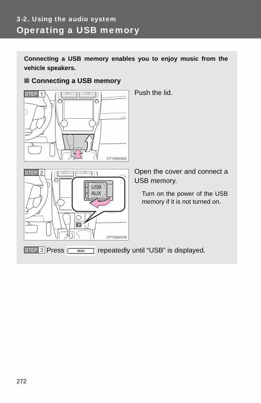
272
3-2. Using the audio system
Operating a USB memory
Connecting a USB memory enables you to enjoy music from thevehicle speakers.
■ Connecting a USB memoryPush the lid.
Open the cover and connect aUSB memory.
Turn on the power of the USBmemory if it is not turned on.
Press repeatedly until “USB” is displayed.
STEP 1
STEP 2
STEP 3

273
3-2. Using the audio system
3
Interior features
Selecting and scanning a folder
■ Selecting a folder
Press or to select the desired folder.
■ Returning to the first file of the first folder
Press and hold until you hear a beep.
■ Control panel
Selecting a file/displaying folder lists
Repeat play
Selecting a file, fast-forwarding or reversing
Power Volume
Back button
Selecting a folder
Random playback
Displaying text messages
Searching playback
Playback/pause

274
3-2. Using the audio system
■ Scanning the first file of all the folders
Press and hold until you hear a beep.
The first 10 seconds of the first file in each folder will be played.
When the desired folder is reached, press again.
■ Selecting from folder lists and file lists
Press .
The folder list will be displayed.
Turn and press to select a folder and a file.
To return to the previous display, press ( ).
Selecting and scanning files
■ Selecting a file
Turn or press or to select the desired file.
■ Scanning the files in a folder
Press .
The first 10 seconds of each file will be played.
When the desired file is reached, press again.
STEP 1
STEP 2
STEP 1
STEP 2
STEP 1
STEP 2

275
3-2. Using the audio system
3
Interior features
Fast-forwarding and reversing files
Press and hold or .
Repeat play
Pressing (RPT) changes modes in the following order:
File repeat → Folder repeat* → Off.
*: Available except when RDM (random playback) is selected
Random playback
Pressing (RDM) changes modes in the following order:
1 folder random → All folders random → Off.
Playing and pausing files
Press ( ).
Switching the display
Press .
Each time is pressed, the display changes in the following order:
Track no./Elapsed time → Folder name → File name → Album title (MP3only) → Track title → Artist name.

276
3-2. Using the audio system
■USB memory functions●Depending on the USB memory that is connected to the system, the
device itself may not be operable and certain functions may not be avail-able. If the device is inoperable or a function is unavailable due to a mal-function (as opposed to a system specification), disconnecting the deviceand reconnecting it once again may resolve the problem.
● If the USB memory still does not begin operation after being discon-nected and reconnected, format the memory.
■Display→P. 253
■Error messages“ERROR”: This indicates a problem in the USB memory or its connection.
“NO MUSIC”: This indicates that no MP3/WMA files are included in the USBmemory.
■USB memory●Compatible devices
USB memory that can be used for MP3 and WMA playback
●Compatible device formats
The following device formats can be used:
• USB communication formats: USB2.0 FS (12 Mbps)• File formats: FAT12/16/32 (Windows)• Correspondence class: Mass storage classMP3 and WMA files written in any format other than those listed abovemay not play correctly, and their file names and folder names may not bedisplayed correctly.
Items related to standards and limitations are as follows:
• Maximum directory hierarchy: 8 levels• Maximum number of folders in a device: 999 (including the root)• Maximum number of files in a device: 9999• Maximum number of files per folder: 255

277
3-2. Using the audio system
3
Interior features
●MP3 and WMA files
MP3 (MPEG Audio LAYER 3) is a standard audio compression format.
Files can be compressed to approximately 1/10 of their original size usingMP3 compression.
WMA (Windows Media Audio) is a Microsoft audio compression format.
This format compresses audio data to a size smaller than that of the MP3format.
There is a limit to the MP3 and WMA file standards that can be used andto the media/formats on which the files are recorded.
●MP3 file compatibility
• Compatible standardsMP3 (MPEG1 AUDIO LAYERIII, MPEG2 AUDIO LAYERIII, MPEG2.5)
• Compatible sampling frequenciesMPEG1 AUDIO LAYERIII: 32, 44.1, 48 (kHz)MPEG2 AUDIO LAYERIII: 16, 22.05, 24 (kHz)MPEG2.5: 8, 11.025, 12 (kHz)
• Compatible bit rates (compatible with VBR)MPEG1 AUDIO LAYERII, III: 32-320 (kbps)MPEG2 AUDIO LAYERII, III: 8-160 (kbps)MPEG2.5: 8-160 (kbps)
• Compatible channel modes: stereo, joint stereo, dual channel andmonaural
●WMA file compatibility
• Compatible standardsWMA Ver. 7, 8, 9
• Compatible sampling frequenciesHIGH PROFILE 32, 44.1, 48 (kHz)
• Compatible bit rates HIGH PROFILE 48-320 (kbps, CBR)
●File names
The only files that can be recognized as MP3/WMA and played are thosewith the extension .mp3 or .wma.

278
3-2. Using the audio system
● ID3 and WMA tags
ID3 tags can be added to MP3 files, making it possible to record the tracktitle, artist name, etc.
The system is compatible with ID3 Ver. 1.0, 1.1, and Ver. 2.2, 2.3, 2.4 ID3tags. (The number of characters is based on ID3 Ver. 1.0 and 1.1.)
WMA tags can be added to WMA files, making it possible to record thetrack title and artist name in the same way as with ID3 tags.
●MP3 and WMA playback
• When a device containing MP3 or WMA files is connected, all files inthe USB memory are checked. Once the file check is finished, the firstMP3 or WMA file is played. To make the file check finish more quickly,we recommend that you do not include any files other than MP3 orWMA files or create any unnecessary folders.
• When the USB memory is connected and the audio source is changedto USB memory mode, the USB memory will start playing the first file inthe first folder. If the same device is removed and reinserted (and thecontents have not been changed), the USB memory will resume playfrom the same point in which it was last used.
●Extensions
If the file extensions .mp3 and .wma are used for files other than MP3 andWMA files, they will be skipped (not played).
●Playback
• To play MP3 files with steady sound quality, we recommend a fixed bitrate of at least 128 kbps and a sampling frequency of 44.1 kHz.
• There is a wide variety of freeware and other encoding software forMP3 and WMA files on the market, and depending on the status of theencoding and the file format, poor sound quality or noise at the start ofplayback may result. In some cases, playback may not be possible atall.
• Microsoft, Windows, and Windows Media are registered trademarks ofMicrosoft Corporation in the U.S.A. and other countries.
CAUTION
■Caution while drivingDo not connect USB memory or operate the controls.

279
3-2. Using the audio system
3
Interior features
NOTICE
■ If the auxiliary box lid cannot be fully closedDepending on the size and shape of the USB memory that is connected tothe system, the auxiliary box lid may not close fully. In this case, do not forc-ibly close the lid as this may damage the USB memory or the terminal, etc.
■To prevent damage to USB memory●Do not leave USB memory in the vehicle. The temperature inside the vehi-
cle may become high, resulting in damage to the player.
●Do not push down on or apply unnecessary pressure to the USB memorywhile it is connected as this may damage the USB memory or its terminal.
●Do not insert foreign objects into the port as this may damage the USBmemory or its terminal.

280
3-2. Using the audio system
Optimal use of the audio system
Using the audio control function
■ Changing sound quality modes
Press .
Turn to select “SOUND”.
Press .
Turn to select the desired mode.
“BAS”, “TRE”, “FAD”, “BAL”, or “ASL”
Press .
Displays the current modeChanges the following set-ting
• Sound quality and volumebalance (→P. 281)
The sound quality and bal-ance setting can be changedto produce the best sound.
• Automatic Sound Levelizer(→P. 281)Selecting the mode
STEP 1
STEP 2
STEP 3
STEP 4
STEP 5

281
3-2. Using the audio system
3
Interior features
■ Adjusting sound quality
Turning adjusts the level.
*: The sound quality level is adjusted individually in each audio mode.
■ Adjusting the Automatic Sound Levelizer (ASL)
When ASL is selected, turn to select the desired mode.
Once the desired mode has been selected, press .
“ASL LOW”, “ASL MID”, “ASL HIGH”, or “ASL OFF”
ASL automatically adjusts the volume and tone quality according to vehi-cle speed.
Sound qual-ity mode
Mode displayed Level Turn to the
leftTurn to the
right
Bass* “BAS” -5 to 5Low High
Treble* “TRE” -5 to 5
Front/rear volume balance
“FAD” F7 to R7 Shifts to rear Shifts to front
Left/right volume balance
“BAL” L7 to R7 Shifts to left Shifts to right

282
3-2. Using the audio system
■Trademark owned by SRS Labs, Inc.
The audio systems utilize SRS FOCUS® and SRS TruBass® audioenhancement technologies, under license from SRS Labs, Inc., in all modesexcept AM radio mode.
FOCUS, TruBass, SRS and symbol are trademarks of SRS Labs,
Inc.FOCUS and TruBass technologies are incorporated under license fromSRS Labs, Inc.
TruBass® enhances the perception of bass frequencies to provide deep, richbass response from any size speaker.
SRS FOCUS® raises the audio image from non-optimally placed speakersup to the natural listening height at ear level.

283
3-2. Using the audio system
3
Interior features
Using the AUX port
■Operating portable audio devices connected to the audio systemThe volume can be adjusted using the vehicle's audio controls. All otheradjustments must be made on the portable audio device itself.
■When using a portable audio device connected to the power outletNoise may occur during playback. Use the power source of the portableaudio device.
This port can be used to connect a portable audio device and listento it through the vehicle’s speakers.
Push the lid.
Open the cover and connectthe portable audio device.
Press repeatedly until “AUX” is displayed.
STEP 1
STEP 2
STEP 3

284
3-2. Using the audio system
NOTICE
■ If the auxiliary box lid cannot be fully closedDepending on the size and shape of the portable audio device that is con-nected to the system, the auxiliary box lid may not close fully. In this case, donot forcibly close the lid as this may damage the portable audio device or theterminal, etc.

285
3
Interior features
3-3. Using the interior lights
Interior lights list
Interior/rear personal lights (vehicles with moon roof) (→P. 286, 287)Interior light (vehicles without moon roof) (→P. 286)Interior/front personal lights (vehicles with moon roof) or per-sonal lights (vehicles without moon roof) (→P. 286, 287)Shift lever light (when the tail lights are on) (vehicles with moonroof)Engine switch light (vehicles without a smart key system)/“ENGINE START STOP” switch light (vehicles with a smart keysystem)Door courtesy lights

286
3-3. Using the interior lights
Interior lights
Vehicles without moon roofTurns the lights onTurns the door position onTurns the lights off
Vehicles with moon roofTurns the lights on/off linked todoor positions.Turns the lights on/off
Interior lights

287
3-3. Using the interior lights
3
Interior features
Personal lights
FrontTurns the lights on/off
Rear (vehicles with moon roof)Turns the lights on/off
Personal lights

288
3-3. Using the interior lights
■ Illuminated entry systemVehicles without a smart key systemThe lights automatically turn on/off according to the engine switch position,whether the doors are locked/unlocked, and whether the doors are open/closed.
Vehicles with a smart key systemThe lights automatically turn on/off according to “ENGINE START STOP”switch mode, the presence of the electronic key, whether the doors arelocked/unlocked, and whether the doors are open/closed.
■To prevent battery dischargeVehicles without a smart key systemIf the interior lights, personal lights and/or door courtesy lights are left onwhen the engine switch is turned to the “LOCK” position, the lights will go offautomatically after 20 minutes.
Vehicles with a smart key systemIf the interior lights, personal lights and/or door courtesy lights are left onwhen the “ENGINE START STOP” switch is turned off, the lights will go offautomatically after 20 minutes.
■Customization that can be configured at Toyota dealerSettings (e.g. the time elapsed before lights turn off) can be changed. (Customizable features →P. 493)
Personal lights

289
3
Interior features
3-4. Using the storage features
List of storage features
CAUTION
■ Items that should not be left in the storage spacesDo not leave glasses, lighters or spray cans in the storage spaces, as thismay cause the following when cabin temperature becomes high:
●Glasses may be deformed by heat or cracked if they come into contactwith other stored items.
●Lighters or spray cans may explode. If they come into contact with otherstored items, the lighter may catch fire or the spray can may release gas,causing a fire hazard.
Auxiliary boxesGlove boxBottle holders/door pocketsCup holdersConsole boxCoin holder

290
3-4. Using the storage features
Glove box
The glove box can be opened by pressing the lock release button,locked and unlocked using the master key (vehicles without a smartkey system) or the mechanical key (vehicles with a smart key sys-tem).
OpenLockUnlock
CAUTION
■Caution while drivingKeep the glove box closed. In the event of sudden braking or sudden swerv-ing, an accident may occur due to an occupant being struck by the openglove box or the items stored inside.
Glove box

291
3-4. Using the storage features
3
Interior features
Console box
Lift the lid while pulling up thelever to release the lock.
■When using the console box lid as an armrest
CAUTION
■Caution while drivingKeep the console box closed. In the event of sudden braking, an accidentmay occur due to an occupant being struck by the open console box or theitems stored inside.
Slide the console box lid forward asneeded. Slide the lid forward while pullingup the lever.
The lid can also be opened from the for-wardmost position.
Console box

292
3-4. Using the storage features
Coin holder
Pull the lid down while pressingdown the button.
CAUTION
■Caution while drivingKeep the coin holder closed. In the event of sudden braking, an accidentmay occur due to an occupant being struck by the open coin holder or theitems stored inside.
Coin holder

293
3-4. Using the storage features
3
Interior features
Bottle holders
Front
Rear
■When using the holder as a bottle holder●When storing a bottle, close the cap.
●The bottle may not be stored depending on its size or shape.
CAUTION
■ Items unsuitable for the bottle holderDo not place anything other than a bottle in the bottle holders.Other items may be thrown out of the holders in the event of an accident orsudden braking and cause injury.
Bottle holders

294
3-4. Using the storage features
Cup holders
Front
RearPull the armrest down.
NOTICE
■ Items that should not be stowed in the bottle holdersPut the cap on before stowing a bottle. Do not place open bottles in the bot-tle holders, or glasses and paper cups containing liquid. The contents mayspill and glasses may break.
Bottle holders and cup holders

295
3-4. Using the storage features
3
Interior features
■Cup holder insert
CAUTION
■ Items unsuitable for the cup holderDo not place anything other than cups or aluminum cans in the cup holders.Other items may be thrown out of the holders in the event of an accident orsudden braking, causing injury. If possible, cover hot drinks to prevent burns.
Cup holder insert can be removed.
Cup holders

296
3-4. Using the storage features
Auxiliary boxes
Type APush the lid.
Type BPush the lid.
Type C (if equipped)Lift the lid.
Auxiliary boxes

297
3-4. Using the storage features
3
Interior features
CAUTION
■Caution while drivingKeep the auxiliary boxes closed. In the event of sudden braking, an accidentmay occur due to an occupant being struck by an open auxiliary box or theitems stored inside.
■ Items unsuitable for storing (type A only)Do not store items heavier than 0.4 lb. (0.2 kg).Doing so may cause the auxiliary box to open and the items inside may fallout, resulting in an accident.
Auxiliary boxes

298
3-5. Other interior features
Sun visors
To set the visor in the for-ward position, flip it down.To set the visor in the sideposition, flip down, unhook,and swing it to the side.To use the side extender,place the visor in the sideposition, then slide it back-ward.

299
3-5. Other interior features
3
Interior features
Vanity mirrors
■To prevent battery discharge (vehicles with vanity lights)If the vanity lights remain on for 20 minutes while the engine is off, the lightswill turn off automatically.
Slide the cover to open.
Vehicles with vanity lights: Thelight turns on when the cover isopened.

300
3-5. Other interior features
Clock
■The clock is displayed whenVehicles without a smart key systemThe engine switch is in the “ACC” or “ON” position.
Vehicles with a smart key systemThe “ENGINE START STOP” switch is in ACCESSORY or IGNITION ONmode.
■When disconnecting and reconnecting battery terminalsThe time display will automatically be set to 1:00.
Adjusts the hoursAdjusts the minutes

301
3-5. Other interior features
3
Interior features
Outside temperature display
■The outside temperature is displayed whenVehicles without a smart key systemThe engine switch is in the “ON” position.
Vehicles with a smart key systemThe “ENGINE START STOP” switch is in IGNITION ON mode.
The temperature display shows temperatures within the range of-40°F (-40°C) and 122°F (50°C).
Type A
Type B
302
3-5. Other interior features
■DisplayIn the following situations, the correct outside temperature may not be dis-played, or the display may take longer than normal to change:
●When the vehicle is stopped, or moving at low speeds (less than 16 mph[25 km/h])
●When the outside temperature has changed suddenly (at the entrance/exit of a garage, tunnel, etc.)
■When “E” is displayedThe system may be malfunctioning. Take your vehicle to your Toyota dealer.

303
3-5. Other interior features
3
Interior features
Ashtray∗
CAUTION
■When not in useKeep the ashtray closed. In the event of sudden braking, an accident mayoccur due to an occupant being struck by the open ashtray or ash flying out.
■To prevent fire●Fully extinguish matches and cigarettes before putting them in the ashtray,
then make sure the ashtray is fully closed.
●Do not place paper or any other type of flammable object in the ashtray.
An ashtray can be installed inthe cup holder. (→P. 294)
∗: If equipped

304
3-5. Other interior features
Power outlets
The power outlet can be used for 12 V accessories that run on lessthan 10 A.
Instrument cluster

305
3-5. Other interior features
3
Interior features
■The power outlet can be used whenVehicles without a smart key system The engine switch is in the “ACC” or “ON” position.
Vehicles with a smart key system The “ENGINE START STOP” switch is in ACCESSORY or IGNITION ONmode.
Center console (if equipped)

306
3-5. Other interior features
NOTICE
■To avoid damaging the power outletClose the power outlet lid when the power outlet is not in use.Foreign objects or liquids that enter the power outlet may cause a short cir-cuit.
■To prevent blown fuseDo not use an accessory that uses more than 12 V 10 A.
■To prevent battery dischargeDo not use the power outlet longer than necessary when the engine is notrunning.

307
3-5. Other interior features
3
Interior features
Seat heaters∗
■The seat heaters can be used whenVehicles without a smart key system The engine switch is in the “ON” position.
Vehicles with a smart key system The “ENGINE START STOP” switch is in IGNITION ON mode.
■When not in useMove the dial fully backward. The indicator light turns off.
On
The indicator light comes on.
Adjusts the seat tempera-ture
The further you move the dialforward, the warmer the seatbecomes.
Driver’s seatFront passenger’s seat
∗: If equipped

308
3-5. Other interior features
CAUTION
■Burns●Use caution when seating the following persons in a seat with the seat
heater on to avoid the possibility of burns:
• Babies, small children, the elderly, the sick and the physically chal-lenged
• Persons with sensitive skin• Persons who are fatigued• Persons who have taken alcohol or drugs that induce sleep (sleeping
drugs, cold remedies, etc.)●Do not cover the seat with anything when using the seat heater.
Using the seat heater with a blanket or cushion increases the temperatureof the seat and may lead to overheating.
●Do not use the seat heater more than necessary. Doing so may causeminor burns or overheating.
NOTICE
■To prevent seat heater damageDo not put heavy objects that have an uneven surface on the seat and donot stick sharp objects (needles, nails, etc.) into the seat.
■To prevent battery dischargeTurn the seat heaters off when the engine is not running.

309
3-5. Other interior features
3
Interior features
Armrest
NOTICE
■To prevent damage to the armrestDo not apply too much load on the armrest.
Fold down the armrest for use.

310
3-5. Other interior features
Coat hooks
CAUTION
■ Items that cannot be hung on the coat hook Do not hang coat hangers or other hard or sharp objects on the hook. If theSRS curtain shield airbags deploy, these items may become projectiles,causing death or serious injury.

311
3-5. Other interior features
3
Interior features
Floor mat
Use only floor mats designed specifically for vehicles of the samemodel and model year as your vehicle. Fix them securely in placeonto the carpet.
Insert the retaining hooks(clips) into the floor mat eye-lets.
Turn the upper knob of eachretaining hook (clip) to securethe floor mats in place.
*: Always align the ∆ marks.
The shape of the retaining hooks (clips) may differ from that shown in theillustration.
STEP 1
STEP 2
*

312
3-5. Other interior features
CAUTION
Observe the following precautions. Failure to do so may cause the driver's floor mat to slip, possibly interferingwith the pedals while driving. An unexpectedly high speed may result or it maybecome difficult to stop the vehicle, leading to a serious accident.
■When installing the driver's floor mat ●Do not use floor mats designed for other models or different model year
vehicles, even if they are Toyota Genuine floor mats.
●Only use floor mats designed for the driver's seat.
●Always install the floor mat securely using the retaining hooks (clips) pro-vided.
●Do not use two or more floor mats on top of each other.
●Do not place the floor mat bottom-side up or upside-down.
■Before driving
●Check that the floor mat is securelyfixed in the correct place with all theprovided retaining hooks (clips). Beespecially careful to perform this checkafter cleaning the floor.
●With the engine stopped and the shiftlever in P, fully depress each pedal tothe floor to make sure it does not inter-fere with the floor mat.

313
3-5. Other interior features
3
Interior features
Trunk features
■ Grocery bag hooks

314
3-5. Other interior features
NOTICE
■To prevent damage to the hooksDo not apply too much load to the hooks.
■ Cargo net (if equipped)

315
3-5. Other interior features
3
Interior features
Garage door opener∗
The garage door opener (HomeLink® Universal Transceiver) is manufac-tured under license from HomeLink®.
Programming HomeLink® (for U.S. owners)
The HomeLink® compatible transceiver in your vehicle has 3 buttonswhich can be programmed to operate 3 different devices. Refer to theprogramming method below appropriate for the device.
ButtonsIndicator
The garage door opener can be programmed to operate garagedoors, gates, entry doors, door locks, home lighting systems, secu-rity systems, and other devices.
∗: If equipped

316
3-5. Other interior features
■ Programming the HomeLink®
Point the remote control trans-mitter for the device 1 to 3 in. (25to 75 mm) from the HomeLink®
control buttons.
Keep the HomeLink® indicatorlight in view while programming.
Press and hold one of theHomeLink® buttons and thetransmitter button. When theHomeLink® indicator lightchanges from a slow to a rapidflash, you can release both but-tons.
If the HomeLink® indicator lightcomes on but does not flash, orflashes rapidly for 2 seconds andremains lit, the HomeLink® buttonis already programmed. Use theother buttons or follow the“Reprogramming a HomeLink®
button” instructions. (→P. 319)
STEP 1
STEP 2

317
3-5. Other interior features
3
Interior features
Test the HomeLink® operationby pressing the newly pro-grammed button.
If a HomeLink® button has beenprogrammed for a garage door,check to see if the garage dooropens and closes. If the garagedoor does not operate, see if yourremote control transmitter is ofthe rolling code type. Press andhold the programmed HomeLink®
button. The remote control trans-mitter is of the rolling code type ifthe HomeLink® indicator lightflashes rapidly for 2 seconds andthen remains lit. If your transmit-ter is of the rolling code type, pro-ceed to the heading“Programming a rolling code sys-tem”.
Repeat the steps above to program another device for any ofthe remaining HomeLink® buttons.
■ Programming a Rolling Code system (for U.S. owners)If your device is Rolling Code equipped, follow the steps under theheading “Programming HomeLink®” before proceeding with thesteps listed below.
Locate the learn button on the ceiling mounted garage dooropener motor. The exact location and color of the button mayvary by brand of garage door opener motor.Refer to the operation manual supplied with the garage door openermotor for the location of the learn button.
Press the learn button.Following this step, you have 30 seconds in which to initiate step 3below.
STEP 3
STEP 4
STEP 1
STEP 2

318
3-5. Other interior features
Press and hold the vehicle’s programmed HomeLink® buttonfor 2 seconds and then release it. Repeat this step onceagain. The garage door may open.If the garage door opens, the programming process is complete. Ifthe door does not open, press and release the button a third time.This third press and release will complete the programming processby opening the garage door.
The ceiling mounted garage door opener motor should now recog-nize the HomeLink® signal and operate the garage door.
Repeat the steps above to program another rolling code sys-tem for any of the remaining HomeLink® buttons.
■ Programming an entry gate (for U.S. owners)/Programming adevice in the Canadian market
Place the remote control transmitter 1 to 3 in. (25 to 75 mm)away from the HomeLink® buttons.Keep the HomeLink® indicator light in view while programming.
Press and hold the selected HomeLink® button.Repeatedly press and release (cycle) the remote controltransmitter for 2 seconds each until step 4 is completed.When the HomeLink® indicator light starts to flash rapidly,release the buttons.Test the HomeLink® operation by pressing the newly pro-grammed button. Check to see if the gate/device operatescorrectly.Repeat the steps above to program another device for any ofthe remaining HomeLink® buttons.
■ Programming other devicesTo program other devices such as home security systems, homedoor locks or lighting, contact your Toyota dealer for assistance.
■ Reprogramming a buttonThe individual HomeLink® buttons cannot be erased but can bereprogrammed. To reprogram a button, follow the “Reprogramminga HomeLink® button” instructions.
STEP 3
STEP 4
STEP 1
STEP 2
STEP 3
STEP 4
STEP 5
STEP 6

319
3-5. Other interior features
3
Interior features
Operating HomeLink®
Press the appropriate HomeLink® button. The HomeLink® indicatorlight should come on.
The HomeLink® compatible transceiver in your vehicle continues to senda signal for up to 20 seconds as long as the button is pressed.
Reprogramming a HomeLink® button
Press and hold the desired HomeLink® button. After 20 seconds, theHomeLink® indicator light will start flashing slowly. Keep pressing theHomeLink® button and press and hold the transmitter button until theHomeLink® indicator light changes from a slow to a rapid flash.Release the buttons.
Erasing the entire HomeLink® memory (all three programs)
Press and hold the 2 outside but-tons for 10 seconds until the indi-cator light flashes.
If you sell your vehicle, be sure toerase the programs stored in theHomeLink® memory.

320
3-5. Other interior features
■Before programming● Install a new battery in the remote control transmitter.
●The battery side of the remote control transmitter must be pointed awayfrom the HomeLink® button.
■To prevent battery dischargeVehicles without a smart key system:HomeLink® will turn off if a door has not been opened and closed for 20 min-utes or the engine switch is left turned off. (After which programming cannotbe completed.) Open and close a door or turn the engine switch to the“ACC” position to turn HomeLink® on. We recommend programming whilethe engine switch is in the “ACC” position.
Vehicles with a smart key system:HomeLink® will turn off if a door has not been opened and closed for 20 min-utes or the “ENGINE START STOP” switch is left turned off. (After which pro-gramming cannot be completed.) Open and close a door or turn the“ENGINE START STOP” switch to ACCESSORY mode to turn HomeLink®
on. We recommend programming while the “ENGINE START STOP” switchis in ACCESSORY mode.
■Certification for the garage door openerU.S.A.FCC ID: CB2051AHL4/CB251AHL4NR
NOTE:This device complies with Part 15 of the FCC Rules. Operation is subject tothe following two conditions: (1) this device may not cause harmful interfer-ence, and (2) this device must accept any interference received, includinginterference that may cause undesired operation.
FCC WARNING:Changes or modifications not expressly approved by the party responsiblefor compliance could void the user's authority to operate the equipment.
CanadaNOTE:Operation is subject to the following two conditions: (1) this device may notcause interference, and (2) this device must accept any interference, includ-ing interference that may cause undesired operation of the device.

321
3-5. Other interior features
3
Interior features
■When support is necessaryVisit on the web at www.homelink.com or call 1-800-355-3515.
CAUTION
■When programming a garage door or other remote control devicesThe garage door or other devices may operate, so ensure people andobjects are out of danger to prevent potential harm.
■Conforming to federal safety standardsDo not use the HomeLink® compatible transceiver with any garage dooropener or device that lacks safety stop and reverse features as required byfederal safety standards.This includes any garage door that cannot detect an interfering object. Adoor or device without these features increases the risk of death or seriousinjury.

322
3-5. Other interior features
Compass∗
The compass on the inside rear view mirror indicates the direction inwhich the vehicle is heading.
■ OperationTo turn the compass on or off,press “AUTO” for more than 3seconds.
■ Displays and directions
Display Direction
N North
NE Northeast
E East
SE Southeast
S South
SW Southwest
W West
NW Northwest
∗: If equipped

323
3-5. Other interior features
3
Interior features
Calibrating the compass
The direction display deviates from the true direction determined bythe earth’s magnetic field. The amount of deviation varies dependingon the geographic position of the vehicle.
If you cross over one of the map boundaries shown in illustration, thecompass will deviate.To obtain higher precision or perfect calibration, refer to “Deviation calibra-tion”.
■ Deviation calibrationStop the vehicle.
Press and hold “AUTO”.
A number (1 to 15) appears onthe compass display.
STEP 1
STEP 2

324
3-5. Other interior features
Referring to the map above, press “AUTO” to select the num-ber of the zone you are in.If the direction is displayed several seconds after adjustment, thecalibration is complete.
■ Circling calibrationWhen “C” appears on the dis-play, drive the vehicle at 5 mph(8 km/h) or less in a circle until adirection is displayed.
If there is not enough space todrive in a circle, drive around theblock until a direction is dis-played.
STEP 3
■Conditions unfavorable to correct operationThe compass may not show the correct direction in the following conditions:
●The vehicle is stopped immediately after turning.
●The vehicle is on an inclined surface.
●The vehicle is in a place where the earth's magnetic field is subject tointerference by artificial magnetic fields (underground car park/parkinglot, under a steel tower, between buildings, roof car park/parking lot, nearan intersection, near a large vehicle, etc.).
●The vehicle has become magnetized.(There is a magnet or metal object near the inside rear view mirror.)
●The battery has been disconnected.
●A door is open.

325
3-5. Other interior features
3
Interior features
CAUTION
■While driving the vehicleDo not adjust the display. Adjust the display only when the vehicle isstopped.
■When doing the circling calibrationSecure a wide space, and watch out for people and vehicles in the vicinity.Do not violate any local traffic rules while performing circling calibration.
NOTICE
■To avoid compass malfunctionsDo not place magnets or any metal objects near the inside rear view mirror. Doing this may cause the compass sensor to malfunction.
■To ensure normal operation of the compass●Do not perform a circling calibration of the compass in a place where the
earth's magnetic field is subject to interference by artificial magnetic fields.
●During calibration, do not operate electric systems (moon roof, power win-dows, etc.) as they may interfere with the calibration.

326
3-5. Other interior features
Safety Connect∗
Safety Connect is a subscription-based telematics service that usesGlobal Positioning System (GPS) data and embedded cellular tech-nology to provide safety and security features to subscribers. SafetyConnect is supported by Toyota’s designated response center,which operates 24 hours per day, 7 days per week.
Safety Connect service is available by subscription on select,telematics hardware-equipped vehicles.
By using the Safety Connect service, you are agreeing to be boundby the Telematics Subscription Service Agreement and its Terms andConditions, as in effect and amended from time to time, a currentcopy of which is available at Toyota.com. All use of the Safety Con-nect service is subject to such then-applicable Terms and Condi-tions.
■ System componentsMicrophoneLED light indicators“SOS” button
∗: if equipped

327
3-5. Other interior features
3
Interior features
■ ServicesSubscribers have the following Safety Connect services avail-able:
● Automatic Collision Notification*Helps drivers receive necessary response from emergencyservice providers. (→P. 329)
*: U.S. Patent No. 7,508,298 B2
● Stolen Vehicle LocationHelps drivers in the event of vehicle theft. (→P. 330)
● Emergency Assistance Button (SOS)Connects drivers to response-center support. (→P. 330)
● Enhanced Roadside AssistanceProvides drivers various on-road assistance. (→P. 330)
■ SubscriptionAfter you have signed the Telematics Subscription ServiceAgreement and are enrolled, you can begin receiving services. A variety of subscription terms is available for purchase. Contactyour Toyota dealer, call 1-800-331-4331, or push the “SOS” but-ton in your vehicle for further subscription details.

328
3-5. Other interior features
■Safety Connect Services Information●Phone calls using the vehicles Bluetooth® technology will not be possible
during Safety Connect.
●Safety Connect is available beginning Fall 2009 on select Toyota models.Contact with the Safety Connect response center is dependent upon thetelematics device being in operative condition, cellular connection avail-ability, and GPS satellite signal reception, which can limit the ability toreach the response center or receive emergency service support. Enroll-ment and Telematics Subscription Service Agreement required. A varietyof subscription terms is available; charges vary by subscription termselected.
●Automatic Collision Notification, Emergency Assistance, Stolen VehicleLocation, and Enhanced Roadside Assistance will function in the UnitedStates, including Hawaii and Alaska, and in Canada. No Safety Connectservices will function outside of the United States in countries other thanCanada.
●Safety Connect services are not subject to section 255 of the Telecom-munications Act and the device is not TTY compatible.
■LanguagesThe Safety Connect response center will offer support in multiple languages.The Safety Connect system will offer voice prompts in English and Spanish.Please indicate your language of choice when enrolling.
■When contacting the response centerYou may be unable to contact the response center if the network is busy.

329
3-5. Other interior features
3
Interior features
Safety Connect LED light Indicators
When the “ENGINE START STOP” switch is turned to IGNITION ONmode (vehicles with a smart key system) or the engine switch isturned to the “ON” position (vehicles without a smart key system), thered indicator light comes on for 2 seconds then turns off. Afterward,the green indicator light comes on, indicating that the service isactive.The following indicator light patterns indicate specific system usageconditions:
● Green indicator light on = Active service
● Green indicator light flashing = Safety Connect call in process
● Red indicator light (except at vehicle start-up) = System malfunc-tion (contact your Toyota dealer)
● No indicator light (off) = Safety Connect service not active
Safety Connect services
■ Automatic Collision NotificationIn case of either airbag deployment or severe rear-end collision,the system is designed to automatically call the response center.The responding agent receives the vehicle’s location and attemptsto speak with the vehicle occupants to assess the level of emer-gency. If the occupants are unable to communicate, the agentautomatically treats the call as an emergency, contacts the nearestemergency services provider to describe the situation, andrequests that assistance be sent to the location.

330
3-5. Other interior features
■ Stolen Vehicle LocationIf your vehicle is stolen, Safety Connect can work with local author-ities to assist them in locating and recovering the vehicle. After fil-ing a police report, call the Safety Connect response center at 1-800-331-4331 and follow the prompts for Safety Connect to initiatethis service.In addition to assisting law enforcement with recovery of a stolenvehicle, Safety-Connect-equipped vehicle location data may, undercertain circumstances, be shared with third parties to locate yourvehicle. Further information is available at Toyota.com.
■ Emergency Assistance Button (“SOS”)In the event of an emergency on the road, push the “SOS” buttonto reach the Safety Connect response center. The answeringagent will determine your vehicle’s location, assess the emer-gency, and dispatch the necessary assistance required.
If you accidentally press the “SOS” button, tell the response-center agentthat you are not experiencing an emergency.
■ Enhanced Roadside AssistanceEnhanced Roadside Assistance adds GPS data to the alreadyincluded warranty-based Toyota roadside service.
Subscribers can press the “SOS” button to reach a Safety Connectresponse-center agent, who can help with a wide range of needs,such as: towing, flat tire, fuel delivery, etc. For a description of theEnhanced Roadside Assistance services and their limitations,please see the Safety Connect Terms and Conditions, which areavailable at Toyota.com.

331
3-5. Other interior features
3
Interior features
Safety information for Safety Connect
Important! Read this information before using Safety Connect.
■ Exposure to radio frequency signalsThe Safety Connect system installed in your vehicle is a low-powerradio transmitter and receiver. It receives and also sends out radiofrequency (RF) signals.
In August 1996, the Federal Communications Commission (FCC)adopted RF exposure guidelines with safety levels for mobile wire-less phones. Those guidelines are consistent with the safety stan-dards previously set by the following U.S. and internationalstandards bodies.
● ANSI (American National Standards Institute) C95.1 [1992]
● NCRP (National Council on Radiation Protection and Measure-ment) Report 86 [1986]
● ICNIRP (International Commission on Non-Ionizing RadiationProtection) [1996]
Those standards were based on comprehensive and periodic eval-uations of the relevant scientific literature. Over 120 scientists,engineers, and physicians from universities, and governmenthealth agencies and industries reviewed the available body ofresearch to develop the ANSI Standard (C95.1).
The design of Safety Connect complies with the FCC guidelines inaddition to those standards.

332
3-5. Other interior features
■Certification for Safety ConnectFCC ID: O9EGTM1
FCC ID: O6Y-CDMRF101
NOTE:This device complies with Part 15 of the FCC Rules. Operation is subject tothe following two conditions: (1) This device may not cause harmful interfer-ence, and (2) this device must accept any interference received, includinginterference that may cause undesired operation.
FCC WARNING:
Changes or modifications not expressly approved by the party responsiblefor compliance could void the user's authority to operate the equipment.

334
4-1. Maintenance and care
Cleaning and protecting the vehicle exterior
■Automatic car washes●Fold the mirrors before washing the vehicle. Start washing from the front
of the vehicle. Make sure to extend the mirrors before driving.
●Brushes used in automatic car washes may scratch the vehicle surfaceand harm your vehicle’s paint.
●Vehicles with rear spoiler: In certain automatic car washes, the rearspoiler may interfere with machine operation. This may prevent the vehi-cle from being cleaned properly or result in damage to the rear spoiler.
■High pressure car washes●Do not allow the nozzles of the car wash to come within close proximity
of the windows.
●Before using the car wash, check that the fuel filler door on your vehicleis closed properly.
Perform the following to protect the vehicle and maintain it in primecondition:
● Working from top to bottom, liberally apply water to the vehiclebody, wheel wells and underside of the vehicle to remove anydirt and dust.
● Wash the vehicle body using a sponge or soft cloth, such as achamois.
● For hard-to-remove marks, use car wash soap and rinse thor-oughly with water.
● Wipe away any water.
● Wax the vehicle when the waterproof coating deteriorates.
If water does not bead on a clean surface, apply wax when the vehiclebody is cool.

335
4-1. Maintenance and care
4
Maintenance and care
■When using a car wash (vehicles with a smart key system)If the door handle becomes wet while the electronic key is within the effec-tive range, the door may lock and unlock repeatedly. In that case, follow thefollowing correction procedures to wash the vehicle:
●Place the electronic key in a location 6 ft. (2 m) or more away from thevehicle. (Take care to ensure that the key is not stolen.)
●Set the electronic key to battery-saving mode to disable the smart keysystem. (→P. 39)
■Aluminum wheels (if equipped)●Remove any dirt immediately by using a neutral detergent. Do not use
hard brushes or abrasive cleaners. Do not use strong or harsh chemicalcleaners. Use the same mild detergent and wax as used on the paint.
●Do not use detergent on the wheels when they are hot, for example afterdriving for long distance in the hot weather.
●Wash detergent from the wheels immediately after use.
■BumpersDo not scrub with abrasive cleaners.
CAUTION
■When washing the vehicleDo not apply water to the inside of the engine compartment. Doing so maycause the electrical components etc. to catch fire.
■Precautions regarding the exhaust pipeExhaust gasses cause the exhaust pipe to become quite hot.
When washing the vehicle, be careful not to touch the pipe until it has cooledsufficiently, as touching a hot exhaust pipe can cause burns.
■ Precaution regarding the Blind Spot MonitorIf the paint of the rear bumper is chipped or scratched, the system may mal-function. If this occurs, consult your Toyota dealer.

336
4-1. Maintenance and care
NOTICE
■To prevent paint deterioration and corrosion on the body and compo-nents (aluminum wheels etc.)●Wash the vehicle immediately in the following cases:
• After driving near the sea coast• After driving on salted roads• If coal tar or tree sap is present on the paint surface• If dead insects, insect droppings or bird droppings are present on the
paint surface• After driving in an area contaminated with soot, oily smoke, mine dust,
iron powder or chemical substances• If the vehicle becomes heavily soiled with dust or mud• If liquids such as benzene and gasoline are spilled on the paint surface
● If the paint is chipped or scratched, have it repaired immediately.
●To prevent the wheels from corroding, remove any dirt and store in a placewith low humidity when storing the wheels.
■Cleaning the exterior lights●Wash carefully. Do not use organic substances or scrub with a hard brush.
This may damage the surfaces of the lights.
●Do not apply wax to the surfaces of the lights.Wax may cause damage to the lenses.

337
4-1. Maintenance and care
4
Maintenance and care
Cleaning and protecting the vehicle interior
The following procedures will help protect your vehicle's interior andkeep it in top condition:
■ Protecting the vehicle interiorRemove dirt and dust using a vacuum cleaner. Wipe dirty sur-faces with a cloth dampened with lukewarm water.
■ Cleaning the leather areas● Remove dirt and dust using a vacuum cleaner.
● Wipe off any excess dirt and dust with a soft cloth dampenedwith diluted detergent.
Use a diluted water solution of approximately 5% neutral wool deter-gent.
● Wring out any excess water from the cloth and thoroughlywipe off all remaining traces of detergent.
● Wipe the surface with a dry, soft cloth to remove any remain-ing moisture. Allow the leather to dry in a shaded and venti-lated area.
■ Cleaning the synthetic leather areas● Remove loose dirt using a vacuum cleaner.
● Apply a mild soap solution to the synthetic leather using asponge or soft cloth.
● Allow the solution to soak in for a few minutes. Remove thedirt and wipe off the solution with a clean, damp cloth.

338
4-1. Maintenance and care
■Caring for leather areasToyota recommends cleaning the interior of the vehicle at least twice a yearto maintain the quality of the vehicle's interior.
■Shampooing the carpetsThere are several commercial foaming-type cleaners available. Use asponge or brush to apply the foam. Rub in overlapping circles. Do not usewater. Wipe dirty surfaces and let them dry. Excellent results are obtained bykeeping the carpet as dry as possible.
■Seat beltsClean with mild soap and lukewarm water using a cloth or sponge. Alsocheck the belts periodically for excessive wear, fraying or cuts.
CAUTION
■Water in the vehicle●Do not splash or spill liquid in the vehicle.
Doing so may cause electrical components etc. to malfunction or catchfire.
●Do not get any of the SRS components or wiring in the vehicle interior wet. (→P. 101)
An electrical malfunction may cause the airbags to deploy or not functionproperly, resulting in death or serious injury.
■Cleaning the interior (especially instrument panel)Do not use polish wax or polish cleaner. The instrument panel may reflect offthe windshield, obstructing the driver's view and leading to an accident,resulting in death or serious injury.

339
4-1. Maintenance and care
4
Maintenance and care
NOTICE
■Cleaning detergents●Do not use the following types of detergent, as they may discolor the vehi-
cle interior or cause streaks or damage to painted surfaces:
• Non-seat portions: Organic substances such as benzene or gasoline,alkaline or acidic solutions, dye, and bleach
• Seats: Alkaline or acidic solutions, such as thinner, benzene, and alco-hol
●Do not use polish wax or polish cleaner. The instrument panel's or otherinterior part’s painted surface may be damaged.
■Preventing damage to leather surfacesObserve the following precautions to avoid damage to and deterioration ofleather surfaces:
●Remove any dust or dirt from leather surfaces immediately.
●Do not expose the vehicle to direct sunlight for extended periods of time.Park the vehicle in the shade, especially during summer.
●Do not place items made of vinyl, plastic, or containing wax on the uphol-stery, as they may stick to the leather surface if the vehicle interior heatsup significantly.
■Water on the floorDo not wash the vehicle floor with water.Vehicle systems such as the audio system may be damaged if water comesinto contact with electrical components such as the audio system above orunder the floor of the vehicle. Water may also cause the body to rust.
■Cleaning the inside of the rear window●Do not use glass cleaner to clean the rear window, as this may cause
damage to the rear window defogger heater wires or antenna. Use a clothdampened with lukewarm water to gently wipe the window clean. Wipe thewindow in strokes running parallel to the heater wires or antenna.
●Be careful not to scratch or damage the heater wires or antenna.

340
4-2. Maintenance
Maintenance requirements
■Repair and replacementIt is recommended that genuine Toyota parts be used for repair to ensureperformance of each system. If non-Toyota parts are used in replacement orif a repair shop other than a Toyota dealer performs repairs, confirm the war-ranty coverage.
■Reset the maintenance data (U.S.A. only)After the required maintenance is performed according to the maintenanceschedule, please reset the maintenance data.To reset the data, follow the procedures described below:
To ensure safe and economical driving, day-to-day care and regularmaintenance are essential. It is the owner’s responsibility to performregular checks. Toyota recommends performing the following main-tenance:
■ General maintenanceGeneral maintenance should be performed on a daily basis.This can be done by yourself or by a Toyota dealer.
■ Scheduled maintenanceScheduled maintenance should be performed at specified inter-vals according to the maintenance schedule.
For details about maintenance items and schedules, refer to the“Scheduled Maintenance Guide” or “Owner’s Manual Supplement”.
■ Do-it-yourself maintenanceYou can perform some maintenance procedures by yourself. Please be aware that do-it-yourself maintenance may affect war-ranty coverage.
The use of Toyota Repair Manuals is recommended.
For details about warranty coverage, see the separate “Owner’s War-ranty Information Booklet” or “Owner’s Manual Supplement”.

341
4-2. Maintenance
4
Maintenance and care
Turn the engine switch (vehicles without a smart key system) or the“ENGINE START STOP” switch (vehicles with a smart key system)off with the trip meter A reading shown. (→P. 172)
While pressing the display change button (→P. 169), turn theengine switch to the “ON” position (vehicles without a smart keysystem) or “ENGINE START STOP” switch to IGNITION ON mode(vehicles with a smart key system)
Continue to press and hold the knob until the trip meter displays“000000”.
■Allow inspection and repairs to be performed by a Toyota dealer●Toyota technicians are well-trained specialists and are kept up to date
with the latest service information. They are well informed about theoperations of all systems on your vehicle.
●Keep a copy of the repair order. It proves that the maintenance that hasbeen performed is under warranty coverage. If any problem should arisewhile your vehicle is under warranty, your Toyota dealer will promptlytake care of it.
CAUTION
■ If your vehicle is not properly maintainedImproper maintenance could result in serious damage to the vehicle andpossible serious injury or death.
■Handling of the battery●Engine exhaust, some of its constituents, and a wide variety of automobile
components contain or emit chemicals known to the State of California tocause cancer and birth defects and other reproductive harm. Work in awell ventilated area.
●Oils, fuels and fluids contained in vehicles as well as waste produced bycomponent wear contain or emit chemicals known to the State ofCalifornia to cause cancer and birth defects or other reproductive harm.Avoid exposure and wash any affected area immediately.
●Battery posts, terminals and related accessories contain lead and leadcompounds which are known to cause brain damage. Wash your handsafter handling. (→P. 363)
STEP 1
STEP 2
STEP 3

342
4-2. Maintenance
General maintenance
Engine compartment
Items Check points
Battery Check the connections. (→P. 363)
Brake fluid Is the brake fluid at the correct level? (→P. 361)
Engine coolant Is the engine coolant at the correct level? (→P. 360)
Engine oil Is the engine oil at the correct level? (→P. 355)
Exhaust system There should not be any fumes or strange sounds.
Radiator/condenserThe radiator and condenser should be free from foreign objects. (→P. 361)
Washer fluid Is there sufficient washer fluid?(→P. 366)
Listed below are the general maintenance items that should be per-formed at the intervals specified in the “Owner's Warranty Informa-tion Booklet” or “Owner’s Manual Supplement/ScheduledMaintenance Guide”. It is recommended that any problem you noticeshould be brought to the attention of your Toyota dealer or qualifiedservice shop for advice.

343
4-2. Maintenance
4
Maintenance and care
Vehicle interior
Items Check points
Accelerator pedal• The accelerator pedal should
move smoothly (without uneven pedal effort or catching).
Automatic transmission “Park” mechanism
• When parked on a slope and the shift lever is in P, is the vehicle securely stopped?
Brake pedal
• Does the brake pedal move smoothly?
• Does the brake pedal have appro-priate clearance from the floor? (→P. 473)
• Does the brake pedal have the correct amount of free play? (→P. 473)
Brakes
• The vehicle should not pull to one side when the brakes are applied.
• The brakes should work effec-tively.
• The brake pedal should not feel spongy.
• The brake pedal should not get too close to the floor when the brakes are applied.
Head restraints (front seat) • Do the head restraints move smoothly and lock securely?
Indicators/buzzers • Do the indicators and buzzers function properly?
Lights • Do all the lights come on?
Parking brake
• Does the parking brake pedal move smoothly?
• When parked on a slope and the parking brake is on, is the vehicle securely stopped?

344
4-2. Maintenance
Seat belts
• Do the seat belts operate smoothly?
• The seat belts should not be dam-aged.
Seats • Do the seat controls operate properly?
Steering wheel
• Does the steering wheel rotate smoothly?
• Does the steering wheel have the correct amount of free play?
• There should not be any strange sounds coming from the steering wheel.
Items Check points

345
4-2. Maintenance
4
Maintenance and care
Vehicle exterior
Items Check points
Doors/trunk • Do the doors and trunk operate smoothly?
Engine hood • Does the engine hood lock sys-tem work properly?
Fluid leaks• There should not be any signs of
fluid leakage after the vehicle has been parked.
Tires
• Is the tire inflation pressure cor-rect?
• The tires should not be dam-aged or excessively worn.
• Have the tires been rotated according to the maintenance schedule?
• The wheel nuts should not be loose.
CAUTION
■ If the engine is runningTurn the engine off and ensure that there is adequate ventilation before per-forming maintenance checks.

346
4-2. Maintenance
Emission inspection and maintenance (I/M) programs
Some states have vehicle emission inspection programs whichinclude OBD (On Board Diagnostics) checks. The OBD system moni-tors the operation of the emission control system.
■ If the malfunction indicator lamp comes onThe OBD system determines that a problem exists somewherein the emission control system. Your vehicle may not pass the I/M test and may need to be repaired. Contact your Toyota dealerto service the vehicle.
■ Your vehicle may not pass the I/M test in the following situa-tions:● When the battery is disconnected or discharged
Readiness codes that are set during ordinary driving areerased.Also, depending on your driving habits, the readiness codesmay not be completely set.
● When the fuel tank cap is loose
The malfunction indicator lamp comes on indicating a tempo-rary malfunction and your vehicle may not pass the I/M test.
■ When the malfunction indicator lamp still remains on afterseveral driving tripsThe error code in the OBD system will not be cleared unless thevehicle is driven 40 or more times.
■ If your vehicle does not pass the I/M testContact your Toyota dealer to prepare the vehicle for re-testing.

347
4
Maintenance and care
4-3. Do-it-yourself maintenance
Do-it-yourself service precautions
If you perform maintenance by yourself, be sure to follow the correctprocedures as given in these sections.
Items Parts and tools
Battery condition (→P. 363)
• Warm water• Baking soda• Grease• Conventional wrench
(for terminal clamp bolts)
Brake fluid level (→P. 361)
• FMVSS No.116 DOT 3 or SAE J1703 brake fluid
• Rag or paper towel• Funnel (used only for adding
brake fluid)
Engine coolant level (→P. 360)
• “Toyota Super Long Life Coolant” or a similar high quality ethylene glycol-based non-silicate, non-amine, non-nitrite and non-borate coolant with long-life hybrid organic acid technologyU.S.A.:“Toyota Super Long Life Coolant” is pre-mixed with 50% coolant and 50% deionized water.Canada:“Toyota Super Long Life Coolant” is pre-mixed with 55% coolant and 45% deionized water.
• Funnel (used only for adding engine coolant)

348
4-3. Do-it-yourself maintenance
Items Parts and tools
Engine oil level (→P. 355)
• “Toyota Genuine Motor Oil” or equivalent
• Rag or paper towel• Funnel (used only for adding
engine oil)
Fuses (→P. 389) • Fuse with same amperage rating as original
Light bulbs (→P. 401)
• Bulb with same number and watt-age rating as original
• Phillips-head screwdriver• Flathead screwdriver• Wrench
Radiator and condenser(→P. 361) ⎯
Tire inflation pressure (→P. 375) • Tire pressure gauge• Compressed air source
Washer fluid (→P. 366)
• Water or washer fluid containing antifreeze (for winter use)
• Funnel (used only for adding water or washer fluid)

349
4-3. Do-it-yourself maintenance
4
Maintenance and care
CAUTION
The engine compartment contains many mechanisms and fluids that maymove suddenly, become hot, or become electrically energized. To avoid deathor serious injury, observe the following precautions:
■When working on the engine compartment:●Keep hands, clothing and tools away from the moving fan and engine
drive belt.
●Be careful not to touch the engine, radiator, exhaust manifold, etc. rightafter driving as they may be hot. Oil and other fluids may also be hot.
●Do not leave anything that may burn easily, such as paper or rags, in theengine compartment.
●Do not smoke, cause sparks or expose an open flame to fuel or the bat-tery. Fuel and battery fumes are flammable.
●Be extremely cautious when working on the battery. It contains poisonousand corrosive sulfuric acid.
■When working near the electric cooling fans or radiator grilleVehicles without a smart key system: Be sure the engine switch is off. Withthe engine switch in the “ON” position, the electric cooling fans may auto-matically start to run if the air conditioning is on and/or the coolant tempera-ture is high. (→P. 361)
Vehicles with a smart key system: Be sure the “ENGINE START STOP”switch is off. With the “ENGINE START STOP” switch in IGNITION ONmode, the electric cooling fans may automatically start to run if the air condi-tioning is on and/or the coolant temperature is high. (→P. 361)
■Safety glassesWear safety glasses to prevent flying or falling material, fluid spray, etc. fromgetting in your eyes.
NOTICE
■ If you remove the air cleaner filterDriving with the air cleaner filter removed may cause excessive engine weardue to dirt in the air. Also, a backfire could cause a fire in the engine com-partment.

350
4-3. Do-it-yourself maintenance
Hood
CAUTION
■Pre-driving checkCheck that the hood is fully closed and locked.If the hood is not locked properly, it may open while the vehicle is in motionand cause an accident, which may result in death or serious injury.
Release the lock from the inside of the vehicle to open the hood.
Pull the hood release lever.
The hood will pop up slightly.
Pull up the auxiliary catchlever and lift the hood.
STEP 1
STEP 2

351
4-3. Do-it-yourself maintenance
4
Maintenance and care
Positioning a floor jack
When raising your vehicle with a floor jack, position the jack cor-rectly. Improper placement may damage your vehicle or cause injury.
■ Front
■ Rear
2.5 L 4-cylinder (2AR-FE) engine
3.5 L V6 (2GR-FE) engine
CTY43AV171

352
4-3. Do-it-yourself maintenance
CAUTION
■When raising your vehicleMake sure to observe the following precautions to reduce the possibility ofdeath or serious injury:
●When using a floor jack, follow the instructions of the manual provided withthe jack.
●Do not use the jack that was supplied with your vehicle.
●Do not put any part of your body underneath the vehicle when it is sup-ported only by the floor jack.
●Always use floor jack and/or automotive jack stands on a solid, flat, levelsurface.
●Do not start the engine while the vehicle is supported by the floor jack.
●Stop the vehicle on level, firm ground, firmly set the parking brake and shiftthe shift lever to P.
●Make sure to set the floor jack properly at the jack point.Raising the vehicle with an improperly positioned floor jack will damagethe vehicle and may cause the vehicle to fall off the floor jack.
●Do not raise the vehicle while someone is in the vehicle.
●When raising the vehicle, do not place any objects on top of or underneaththe floor jack.
●Lift up the vehicle using a floor jacksuch as the one shown in the illustra-tion.

353
4-3. Do-it-yourself maintenance
4
Maintenance and care
Engine compartment
2.5 L 4-cylinder (2AR-FE) engine
Engine oil filler cap(→P. 357)
Engine oil level dipstick(→P. 355)
Brake fluid reservoir(→P. 361)
Fuse box (→P. 389)
Battery (→P. 363)Radiator (→P. 361)Electric cooling fansCondenser (→P. 361)Engine coolant reservoir
(→P. 360)Washer fluid tank (→P. 366)

354
4-3. Do-it-yourself maintenance
3.5 L V6 (2GR-FE) engine
Engine oil filler cap(→P. 357)
Engine oil level dipstick(→P. 355)
Brake fluid reservoir(→P. 361)
Fuse box (→P. 389)
Battery (→P. 363)Radiator (→P. 361)Electric cooling fansCondenser (→P. 361)Engine coolant reservoir
(→P. 360)Washer fluid tank (→P. 366)

355
4-3. Do-it-yourself maintenance
4
Maintenance and care
Engine oil
With the engine at operating temperature and turned off, check the oillevel on the dipstick.
■ Checking the engine oilPark the vehicle on level ground. After warming up the engineand turning it off, wait more than 5 minutes for the oil to drainback into the bottom of the engine.Hold a rag under the end, pull the dipstick out.
2.5 L 4-cylinder (2AR-FE) engine
3.5 L V6 (2GR-FE) engine
Wipe the dipstick clean.Reinsert the dipstick fully.Holding a rag under the end, pull the dipstick out and checkthe oil level.Wipe the dipstick and reinsert it fully.
STEP 1
STEP 2
STEP 3
STEP 4
STEP 5
STEP 6

356
4-3. Do-it-yourself maintenance
2.5 L 4-cylinder (2AR-FE) engineLowFull
3.5 L V6 (2GR-FE) engineLowFull

357
4-3. Do-it-yourself maintenance
4
Maintenance and care
■ Adding engine oilIf the oil level is below or nearthe low level mark, add engineoil of the same type as thatalready in the engine.
Make sure to check the oil type and prepare the items needed beforeadding oil.
Remove the oil filler cap by turning it counterclockwise.Add engine oil slowly, checking the dipstick.Install the oil filler cap by turning it clockwise.
Engine oil selection →P. 469
Oil quantity(Low → Full) 1.6 qt. (1.5 L, 1.3 lmp. qt.)
Items Clean funnel
STEP 1
STEP 2
STEP 3

358
4-3. Do-it-yourself maintenance
■Engine oil consumption●The amount of engine oil consumed depends on the oil viscosity, the
quality of the oil and the way the vehicle is driven.
●More oil is consumed under driving conditions such as high speeds andfrequent acceleration and deceleration.
●A new engine consumes more oil.
●When judging the amount of oil consumption, keep in mind that the oilmay have become diluted, making it difficult to judge the true level accu-rately.
●Oil consumption: Max. 1.1 qt./600 miles (0.9 Imp. qt./600 miles, 1.0 L/1000 km)
● If your vehicle consumes more than 1.1 qt. (1.0 L, 0.9 Imp. qt.) every 600miles (1000 km), contact your Toyota dealer.
CAUTION
■Used engine oil●Used engine oil contains potentially harmful contaminants which may
cause skin disorders such as inflammation or skin cancer, so care shouldbe taken to avoid prolonged and repeated contact. To remove used engineoil from your skin, wash thoroughly with soap and water.
●Dispose of used oil and filters only in a safe and acceptable manner. Donot dispose of used oil and filters in household trash, in sewers or onto theground. Call your Toyota dealer, service station or auto parts store forinformation concerning recycling or disposal.
●Do not leave used engine oil within the reach of children.

359
4-3. Do-it-yourself maintenance
4
Maintenance and care
NOTICE
■To prevent serious engine damageCheck the oil level on a regular basis.
■When replacing the engine oil●Be careful not to spill engine oil on the vehicle components.
●Avoid overfilling, as the engine could be damaged.
●Check the oil level on the dipstick every time you refill the vehicle.
●Be sure the engine oil filler cap is properly tightened.

360
4-3. Do-it-yourself maintenance
Engine coolant
The coolant level is satisfactory if it is between the “F” and “L” lines onthe reservoir when the engine is cold.
Reservoir cap“F” line“L” line
If the level is on or below the “L”line, add coolant up to the “F” line.(→P. 459)
■Coolant selectionOnly use “Toyota Super Long Life Coolant” or a similar high quality ethyleneglycol based non-silicate, non-amine, non-nitrite, and non-borate coolantwith long-life hybrid organic acid technology.
U.S.A.: “Toyota Super Long Life Coolant” is a mixture of 50% coolantand 50% deionized water. (Minimum temperature: -31°F [-35°C])
Canada: “Toyota Super Long Life Coolant” is a mixture of 55% coolantand 45% deionized water. (Minimum temperature: -44°F [-42°C])
For more details about engine coolant, contact your Toyota dealer.
■ If the coolant level drops within a short time of replenishingVisually check the radiator, hoses, engine coolant reservoir caps, drain cockand water pump. If you cannot find a leak, have your Toyota dealer test the cap and check forleaks in the cooling system.
CAUTION
■When the engine is hotDo not remove the engine coolant reservoir cap. The cooling system may be under pressure and may spray hot coolant if thecap is removed, causing serious injuries, such as burns.

361
4-3. Do-it-yourself maintenance
4
Maintenance and care
Radiator and condenser
Check the radiator and condenser and clear away any foreignobjects. If either of the above parts is extremely dirty or you are not sure oftheir condition, have your vehicle inspected by your Toyota dealer.
Brake fluid
■ Checking fluid levelThe brake fluid level should bebetween the “MAX” and “MIN”lines on the tank.
“MAX”“MIN”
NOTICE
■When adding coolantCoolant is neither plain water nor straight antifreeze. The correct mixture ofwater and antifreeze must be used to provide proper lubrication, corrosionprotection and cooling. Be sure to read the antifreeze or coolant label.
■ If you spill coolantBe sure to wash it off with water to prevent it from damaging parts or paint.
CAUTION
■When the engine is hotDo not touch the radiator or condenser as they may be hot and cause seri-ous injuries, such as burns.

362
4-3. Do-it-yourself maintenance
■ Adding fluidMake sure to check the fluid type and prepare the necessary item.
Fluid type FMVSS No.116 DOT 3 or SAE J1703 brake fluid
Item Clean funnel
■Brake fluid can absorb moisture from the airExcess moisture in the brake fluid can cause a dangerous loss of brakingefficiency. Use only newly opened brake fluid.
CAUTION
■When filling the reservoirTake care as brake fluid can harm your hands and eyes and damage paintedsurfaces.If fluid gets on your hands or in your eyes, flush the affected area with cleanwater immediately.
If you still experience discomfort, see a doctor.
NOTICE
■ If the fluid level is low or highIt is normal for the brake fluid level to go down slightly as the brake padswear out or when the fluid level in the accumulator is high.If the reservoir needs frequent refilling, there may be a serious problem.

363
4-3. Do-it-yourself maintenance
4
Maintenance and care
Battery
Check the battery as follows:
Make sure that the battery terminals are not corroded and thatthere are no loose connections, cracks, or loose clamps.
TerminalsHold-down clamp
■Before rechargingWhen recharging, the battery produces hydrogen gas which is flammableand explosive. Therefore, observe the following before recharging:
● If recharging with the battery installed on the vehicle, be sure to discon-nect the ground cable.
●Make sure the power switch on the charger is off when connecting anddisconnecting the charger cables to the battery.

364
4-3. Do-it-yourself maintenance
■After recharging/reconnecting the battery (vehicles with a smart keysystem)●Unlocking the doors using the smart key system may not be possible
immediately after reconnecting the battery. If this happens, use the wire-less remote control or the mechanical key to lock/unlock the doors.
●Start the engine with the “ENGINE START STOP” switch in ACCES-SORY mode. The engine may not start with the “ENGINE START STOP”switch turned off. However, the engine will operate normally from the sec-ond attempt.
●The “ENGINE START STOP” switch mode is recorded by the vehicle. Ifthe battery is reconnected, the vehicle will return the “ENGINE STARTSTOP” switch mode to the status it was in before the battery was discon-nected. Make sure to turn off the engine before disconnect the battery.Take extra care when connecting the battery if the “ENGINE STARTSTOP” switch mode prior to discharge is unknown.
If the engine will not start even after multiple attempts, contact your Toyotadealer.
CAUTION
■Chemicals in the batteryBatteries contains poisonous and corrosive sulfuric acid and may producehydrogen gas which is flammable and explosive. To reduce the risk of deathor serious injury, take the following precautions while working on or near thebattery:
●Do not cause sparks by touching the battery terminals with tools.
●Do not smoke or light a match near the battery.
●Avoid contact with eyes, skin and clothes.
●Never inhale or swallow electrolyte.
●Wear protective safety glasses when working near the battery.
●Keep children away from the battery.

365
4-3. Do-it-yourself maintenance
4
Maintenance and care
CAUTION
■Where to safely charge the batteryAlways charge the battery in an open area. Do not charge the battery in agarage or closed room where there is insufficient ventilation.
■How to recharge the batteryOnly perform a slow charge (5 A or less). The battery may explode ifcharged at a quicker rate.
■Emergency measures regarding electrolyte● If electrolyte gets in your eyes
Flush your eyes with clean water for at least 15 minutes and get immedi-ate medical attention. If possible, continue to apply water with a sponge orcloth while traveling to the nearest medical facility.
● If electrolyte gets on your skinWash the affected area thoroughly. If you feel pain or burning, get medicalattention immediately.
● If electrolyte gets on your clothesIt can soak through clothing on to your skin. Immediately take off the cloth-ing and follow the procedure above if necessary.
● If you accidentally swallow electrolyteDrink a large quantity of water or milk. Get emergency medical attentionimmediately.
NOTICE
■When recharging the batteryNever recharge the battery while the engine is running. Also, be sure allaccessories are turned off.

366
4-3. Do-it-yourself maintenance
Washer fluid
Add washer fluid in the followingsituations.
● Any washer does not work.
● The low washer fluid warninglight comes on.
CAUTION
■When adding washer fluidDo not add washer fluid when the engine is hot or running as washer fluidcontains alcohol and may catch fire if spilled on the engine etc.
NOTICE
■Do not use any fluid other than washer fluidDo not use soapy water or engine antifreeze instead of washer fluid. Doing so may cause streaking on the vehicle’s painted surfaces.
■Diluting washer fluidDilute washer fluid with water as necessary. Refer to the freezing temperatures listed on the label of the washer fluid bot-tle.

367
4-3. Do-it-yourself maintenance
4
Maintenance and care
Tires
Replace or rotate tires in accordance with maintenance sched-ules and treadwear.
■ Checking tiresNew treadTreadwear indicatorWorn tread
The location of treadwearindicators is shown by the“TWI” or “ ” marks, etc.,molded on the sidewall ofeach tire.
Check spare tire conditionand pressure if not rotated.
■ Tire rotationRotate the tires in the ordershown.
To equalize tire wear andextend tire life, Toyota recom-mends that tire rotation iscarried out at the same inter-val as tire inspection.
■ Tire pressure warning system (if equipped) Your vehicle is equipped with a tire pressure warning systemthat uses tire pressure warning valves and transmitters to detectlow tire inflation pressure before serious problems arise. (→P. 423)
Front

368
4-3. Do-it-yourself maintenance
Installing tire pressure warning valves and transmitters
When replacing tires or wheels, tire pressure warning valves andtransmitters must also be installed.
When new tire pressure warning valves and transmitters areinstalled, new ID codes must be registered in the tire pressure warn-ing computer and the tire pressure warning system must be initial-ized. Have tire pressure warning valve and transmitter ID codesregistered by your Toyota dealer. (→P. 369)
■ The tire pressure warning system must be initialized in the fol-lowing circumstances:● When the tire inflation pressure is changed such as when
changing travelling speed or load weight
● When changing the tire size
When the tire pressure warning system is initialized, the current tireinflation pressure is set as the benchmark pressure.
■ How to initialize the tire pressure warning systemPark the vehicle in a safe place and turn the engine switch(vehicles without a smart key system) or the “ENGINE STARTSTOP” switch (vehicles with a smart key system) off.Initialization cannot be performed while the vehicle is moving.
Adjust the tire inflation pressure to the specified cold tire infla-tion pressure level. (→P. 474)Make sure to adjust the tire pressure to the specified cold tireinflation pressure level. The tire pressure warning system willoperate based on this pressure level.
Turn the engine switch to the “ON” position (vehicles without asmart key system) or “ENGINE START STOP” switch to IGNI-TION ON mode (vehicles with a smart key system).
STEP 1
STEP 2
STEP 3

369
4-3. Do-it-yourself maintenance
4
Maintenance and care
Press and hold the tire pressurewarning reset switch until the tirepressure warning light blinksslowly 3 times.
Vehicles without a smart key system: Wait for a few minuteswith the engine switch in the “ON” position and then turn theengine switch to the “ACC” or “LOCK” position. Vehicles with a smart key system: Wait for a few minutes withthe “ENGINE START STOP” switch in IGNITION ON modeand then turn the “ENGINE START STOP” switch off.
Registering ID codes
The tire pressure warning valve and transmitter is equipped with aunique ID code. When replacing a tire pressure warning valve andtransmitter, it is necessary to register the ID code. Have the ID coderegistered by your Toyota dealer.
STEP 4
STEP 5

370
4-3. Do-it-yourself maintenance
■When to replace your vehicle’s tiresTires should be replaced if:●You have tire damage such as cuts, splits, cracks deep enough to
expose the fabric, and bulges indicating internal damage●A tire goes flat repeatedly or cannot be properly repaired due to the
size or location of a cut or other damageIf you are not sure, consult with your Toyota dealer.
■Replacing tires and wheels If the ID code of the tire pressure warning valve and transmitter is notregistered, the tire pressure warning system will not work properly. Afterdriving for about 20 minutes, the tire pressure warning light blinks for 1minute and stays on to indicate a system malfunction.
■Tire lifeAny tire over 6 years old must be checked by a qualified technician evenif it has seldom or never been used or damage is not obvious.
■Routine tire inflation pressure checks The tire pressure warning system does not replace routine tire inflationpressure checks. Make sure to check tire inflation pressure as part ofyour routine of daily vehicle checks.
■Low profile tires (vehicles with 18-inch tires) Generally, low profile tires will wear more rapidly and tire grip perfor-mance will be reduced on snowy and/or icy roads when compared tostandard tires. Be sure to use snow tires or tire chains on snowy and/oricy roads and drive carefully at a speed appropriate for road and weatherconditions.

371
4-3. Do-it-yourself maintenance
4
Maintenance and care
■Maximum load of tire Check that the maximum load of the replacement tire is greater than 1/2of the Gross Axle Weight Ratings (GAWR) of either the front axle or therear axle, whichever is greater.
■Tire types ●Summer tires
Summer tires are high-speed performance tires best suited to highwaydriving under dry conditions. Since summer tires do not have the sametraction performance as snow tires, summer tires are inadequate fordriving on snow-covered or icy roads. For driving on snow-coveredroads or icy roads, the use of snow tires is recommended. Wheninstalling snow tires, be sure to replace all four tires.
●All season tiresAll season tires are designed to provide better traction in snow and tobe adequate for driving in most winter conditions as well as for useyear-round. All season tires, however, do not have adequate tractionperformance compared with snow tires in heavy or loose snow. Also,all season tires fall short in acceleration and handling performancecompared with summer tires in highway driving.
●Snow tiresFor driving on snow-covered roads or icy roads, we recommend usingsnow tires. If you need snow tires, select tires of the same size, con-struction and load capacity as the originally installed tires. Since yourvehicle has radial tires as original equipment, make sure your snowtires also have radial construction. Do not install studded tires withoutfirst checking local regulations for possible restrictions. Snow tiresshould be installed on all wheels. (→P. 218)
For the GAWR, see the CertificationLabel. For the maximum load of thetire, see the load limit at maximum coldtire inflation pressure mentioned on thesidewall of the tire. (→P. 481)

372
4-3. Do-it-yourself maintenance
■ Initializing the tire pressure warning system Initialize the system with the tire inflation pressure adjusted to the speci-fied level.
■ If the tread on snow tires wears down below 0.16 in. (4 mm)The effectiveness of the tires as snow tires is lost.
■ If you press the tire pressure warning reset switch accidentallyIf initialization is performed, adjust the tire inflation pressure to the speci-fied level and initialize the tire pressure warning system again.
■When the initialization of the tire pressure warning system hasfailedInitialization can be completed in a few minutes. However, in the follow-ing cases, the settings have not been recorded and the system will notoperate properly. If repeated attempts to record tire inflation pressuresettings are unsuccessful, have the vehicle inspected by your Toyotadealer.●When operating the tire pressure warning reset switch, the tire pres-
sure warning light does not blink 3 times.●After driving for a certain period of time since the initialization has
been completed, the warning light comes on after blinking for 1minute.
■Certification for the tire pressure warning systemFCC ID: PAXPMVC010FCC ID: HYQ23AADNOTE:This device complies with Part 15 of the FCC Rules. Operation is subjectto the following two conditions: (1) This device may not cause harmfulinterference, and (2) this device must accept any interference received,including interference that may cause undesired operation.FCC WARNING: Changes or modifications not expressly approved by the party responsi-ble for compliance could void the user's authority to operate the equip-ment.

373
4-3. Do-it-yourself maintenance
4
Maintenance and care
CAUTION
■When inspecting or replacing tiresObserve the following precautions to prevent accidents.Failure to do so may cause damage to parts of the drive train as well asdangerous handling characteristics, which may lead to an accidentresulting in death or serious injury.●Do not mix tires of different makes, models or tread patterns.
Also, do not mix tires of remarkably different treadwear.●Do not use tire sizes other than those recommended by Toyota.●Do not mix differently constructed tires (radial, bias-belted or bias-ply
tires).●Do not mix summer, all season and snow tires.●Do not use tires that have been used on another vehicle.
Do not use tires if you do not know how they were used previously. ■When initializing the tire pressure warning system
Do not operate the tire pressure warning reset switch without first adjust-ing the tire inflation pressure to the specified level. Otherwise, the tirepressure warning light may not come on even if the tire inflation pressureis low, or it may come on when the tire inflation pressure is actually nor-mal.

374
4-3. Do-it-yourself maintenance
NOTICE
■Repairing or replacing tires, wheels, tire pressure warning valves,transmitters and tire valve caps●When removing or fitting the wheels, tires or the tire pressure warning
valves and transmitters, contact your Toyota dealer as the tire pres-sure warning valves and transmitters may be damaged if not handledcorrectly.
●When replacing tire valve caps, do not use tire valve caps other thanthose specified. The cap may become stuck.
■To avoid damage to the tire pressure warning valves and transmit-tersWhen a tire is repaired with liquid sealants, the tire pressure warningvalve and transmitter may not operate properly. If a liquid sealant isused, contact your Toyota dealer or other qualified service shop as soonas possible. Make sure to replace the tire pressure warning valve andtransmitter when replacing the tire. (→P. 368)
■Driving on rough roadsTake particular care when driving on roads with loose surfaces or pot-holes.These conditions may cause losses in tire inflation pressure, reducingthe cushioning ability of the tires. In addition, driving on rough roads maycause damage to the tires themselves, as well as the vehicle’s wheelsand body.
■Low profile tires (vehicles with 18-inch tires)Low profile tires may cause greater damage than usual to the tire wheelwhen sustaining impact from the road surface. Therefore, pay attentionto the following:●Be sure to use proper tire inflation pressure. If tires are under-inflated,
they may be damaged more severely.●Avoid potholes, uneven pavement, curbs and other road hazards. Fail-
ure to do so may lead to severe tire and wheel damage.■ If tire inflation pressure of each tire becomes low while driving
Do not continue driving, or your tires and/or wheels may be ruined.

375
4-3. Do-it-yourself maintenance
4
Maintenance and care
Tire inflation pressure
■ Tire inflation pressureThe recommended cold tire inflation pressure and tire size aredisplayed on the tire and loading information label. (→P. 474)

376
4-3. Do-it-yourself maintenance
■Tire inflation pressure check intervalYou should check tire inflation pressure every two weeks, or at leastonce a month.Do not forget to check the spare.
■ Inspection and adjustment procedureTire valveTire pressure gauge
Remove the tire valve cap.Press the tip of the tire pressure gauge onto the tire valve.Read the pressure using the gauge gradations.If the tire inflation pressure is not at the recommendedlevel, adjust the pressure.If you add too much air, press the center of the valve todeflate.After completing the tire inflation pressure measurementand adjustment, apply soapy water to the valve and checkfor leakage.Put the tire valve cap back on.
STEP 1
STEP 2
STEP 3
STEP 4
STEP 5
STEP 6

377
4-3. Do-it-yourself maintenance
4
Maintenance and care
■Effects of incorrect tire inflation pressureDriving with incorrect tire inflation pressure may result in the following:●Reduced fuel efficiency●Reduced driving comfort and tire life●Reduced safety●Damage to the drive trainIf a tire needs frequent inflating, have it checked by your Toyota dealer.
■ Instructions for checking tire inflation pressureWhen checking tire inflation pressure, observe the following:●Check only when the tires are cold.
If your vehicle has been parked for at least 3 hours or has not beendriven for more than 1 mile or 1.5 km, you will get an accurate coldtire inflation pressure reading.
●Always use a tire pressure gauge.The appearance of the tire can be misleading. In addition, tire infla-tion pressure that is even just a few pounds off can affect ride qualityand handling.
●Do not reduce tire inflation pressure after driving. It is normal for tireinflation pressure to be higher after driving.
●Never exceed the vehicle capacity weight.Passengers and luggage weight should be placed so that the vehicleis balanced.

378
4-3. Do-it-yourself maintenance
CAUTION
■Proper inflation is critical to save tire performanceKeep your tires properly inflated. Otherwise, the following conditionsmay occur and result in an accident causing death or serious injury:●Excessive wear●Uneven wear●Poor handling●Possibility of blowouts resulting from overheated tires●Poor sealing of the tire bead●Wheel deformation and/or tire separation●A greater possibility of tire damage from road hazards
NOTICE
■When inspecting and adjusting tire inflation pressureBe sure to put the tire valve caps back on.Without the valve caps, dirt or moisture could get into the valve andcause air leakage, which could result in an accident. If the caps are lost,replace them as soon as possible.

379
4-3. Do-it-yourself maintenance
4
Maintenance and care
Wheels
If a wheel is bent, cracked or heavily corroded, it should bereplaced. Otherwise, the tire may separate from the wheel orcause a loss of handling control.
■ Wheel selectionWhen replacing wheels, care should be taken to ensure thatthey are equivalent to those removed in load capacity, diameter,rim width, and inset*.Replacement wheels are available at your Toyota dealer.
*: Conventionally referred to as “offset”.
Toyota does not recommend using the following:
● Wheels of different sizes or types
● Used wheels
● Bent wheels that have been straightened
■ Aluminum wheel precautions (if equipped)● Use only Toyota wheel nuts and wrenches designed for use
with your aluminum wheels.
● When rotating, repairing or changing your tires, check that thewheel nuts are still tight after driving 1000 miles (1600 km).
● Be careful not to damage the aluminum wheels when usingtire chains.
● Use only Toyota genuine balance weights or equivalent anduse a plastic or rubber hammer when balancing your wheels.

380
4-3. Do-it-yourself maintenance
■When replacing wheels (vehicles with a tire pressure warning sys-tem)The wheels of your vehicle are equipped with tire pressure warningvalves and transmitters that allow the tire pressure warning system toprovide advance warning in the event of a loss in tire inflation pressure.Whenever wheels are replaced, tire pressure warning valves and trans-mitters must be installed. (→P. 368)
CAUTION
■When replacing wheels●Do not use wheels that are a different size from those recommended in
the Owner’s Manual, as this may result in loss of handling control.●Never use an inner tube in a leaking wheel which is designed for a
tubeless tire. Doing so may result in an accident, causing death or seri-ous injury.
■When installing the wheel nuts
●Never use oil or grease on the wheel bolts or wheel nuts.Oil and grease may cause the wheel nuts to be excessively tightened,leading to bolt or disc wheel damage. In addition, the oil or grease cancause the wheel nuts to loosen and the wheel may fall off, causing anaccident and resulting in death or serious injury. Remove any oil orgrease from the wheel bolts or wheel nuts.
●Be sure to install the wheel nuts withthe tapered ends facing inward.Installing the nuts with the taperedends facing outward can cause thewheel to break and eventually causethe wheel to come off while driving,which could lead to an accidentresulting in death or serious injury.
Tapered portion

381
4-3. Do-it-yourself maintenance
4
Maintenance and care
NOTICE
■Replacing tire pressure warning valves and transmitters (vehicleswith a tire pressure warning system)●Because tire repair or replacement may affect the tire pressure warn-
ing valves and transmitters, make sure to have tires serviced by yourToyota dealer or other qualified service shop. In addition, make sure topurchase your tire pressure warning valves and transmitters at yourToyota dealer.
●Ensure that only genuine Toyota wheels are used on your vehicle.Tire pressure warning valves and transmitters may not work properlywith non-genuine wheels.

382
4-3. Do-it-yourself maintenance
Air conditioning filter
The air conditioning filter must be changed regularly to maintain airconditioning efficiency.
■ Removal methodVehicles without a smart key system: Turn the engineswitch off.Vehicles with a smart key system: Turn the “ENGINESTART STOP” switch off.
Open the glove box andremove the glove box coverinside the glove box.
Remove the filter cover.
■ Replacement methodRemove the air conditioningfilter and replace it with a newone.
The “↑UP” marks shown onthe filter should be pointing up.
STEP 1
STEP 2
STEP 3

383
4-3. Do-it-yourself maintenance
4
Maintenance and care
■Checking intervalInspect and replace the air conditioning filter according to the maintenanceschedule. In dusty areas or areas with heavy traffic flow, early replacementmay be required. (For scheduled maintenance information, please refer tothe “Scheduled Maintenance Guide” or “Owner’s Manual Supplement”.)
■ If air flow from the vents decreases dramaticallyThe filter may be clogged. Check the filter and replace if necessary.
NOTICE
■When using the air conditioning systemMake sure that a filter is always installed.Using the air conditioning system without a filter may cause damage to thesystem.

384
4-3. Do-it-yourself maintenance
Wireless remote control/electronic key battery∗
∗: If equipped
Replace the battery with a new one if it is depleted.
■ You will need the following items:● Flathead screwdriver
● Small flathead screwdriver
● Lithium battery CR2016 (vehicles without a smart key sys-tem), or CR2032 (vehicles with a smart key system)
■ Replacing the battery (vehicles without a smart key system)
Type ARemove the cover.
To prevent damage to the key,cover the tip of the screwdriverwith a rag.
To prevent the buttons frombeing disassembled, face thebutton surface downward.
Remove the module.
STEP 1
STEP 2

385
4-3. Do-it-yourself maintenance
4
Maintenance and care
Open the case cover using acoin protected with tape etc.and remove the depleted bat-tery.
Insert a new battery with the“+” terminal facing up.
Type BRemove the cover.
To prevent damage to the key,cover the tip of the screwdriverwith a rag.
To prevent the buttons frombeing disassembled, face thebutton surface downward.
Remove the module.
STEP 3
STEP 1
STEP 2

386
4-3. Do-it-yourself maintenance
Open the case cover using acoin protected with tape etc.and remove the depleted bat-tery using a small flatheadscrewdriver.
Insert a new battery with the“+” terminal facing up.
■ Replacing the battery (vehicles with a smart key system)Take out the mechanical key.
Remove the cover.
To prevent damage to the key,cover the tip of the screwdriverwith a rag.
STEP 3
STEP 1
STEP 2

387
4-3. Do-it-yourself maintenance
4
Maintenance and care
■Use a CR2016 (vehicles without a smart key system) or CR2032 (vehi-cles with a smart key system) lithium battery●Batteries can be purchased at your Toyota dealer, local electrical appli-
ance shops or camera stores.
●Replace only with the same or equivalent type recommended by themanufacturer.
●Dispose of used batteries according to local laws.
■ If the key battery is depletedThe following symptoms may occur:
●The smart key system and wireless remote control will not function prop-erly.
●The operational range will be reduced.
CAUTION
■Removed battery and other partsKeep away from children. These parts are small and if swallowed by a child,they can cause choking. Failure to do so could result in death or seriousinjury.
Remove the depleted batteryusing a small flathead screw-driver.
Insert a new battery with the“+” terminal facing up.
STEP 3

388
4-3. Do-it-yourself maintenance
NOTICE
■For normal operation after replacing the batteryObserve the following precautions to prevent accidents:
●Always work with dry hands.Moisture may cause the battery to rust.
●Do not touch or move any other components inside the remote control.
●Do not bend either of the battery terminals.

389
4-3. Do-it-yourself maintenance
4
Maintenance and care
Checking and replacing fuses
If any of the electrical components do not operate, a fuse may haveblown. If this happens, check and replace the fuses as necessary.
Vehicles without a smart key system: Turn the engineswitch off.Vehicles with a smart key system: Turn the “ENGINESTART STOP” switch off.Open the fuse box cover.
Engine compartmentPush the tabs in and lift the lidoff.
Under the instrument panelRemove the lid.
After a system failure, see “Fuse layout and amperage rat-ings” (→P. 392) for details about which fuse to check.
STEP 1
STEP 2
STEP 3

390
4-3. Do-it-yourself maintenance
Remove the fuse.
Only type A fuse can beremoved using the pullouttool.
Check if the fuse has blown.
Type ANormal fuseBlown fuse
Replace the blown fuse with anew fuse of an appropriateamperage rating. The amper-age rating can be found on thefuse box lid.
Type BNormal fuseBlown fuse
Replace the blown fuse with anew fuse of an appropriateamperage rating. The amper-age rating can be found on thefuse box lid.
STEP 4
STEP 5

391
4-3. Do-it-yourself maintenance
4
Maintenance and care
Type CNormal fuseBlown fuse
Contact your Toyota dealer.

392
4-3. Do-it-yourself maintenance
Fuse layout and amperage ratings
■ Engine compartment
Fuse block
Fuse block on the back of the cover

393
4-3. Do-it-yourself maintenance
4
Maintenance and care
Fuse Ampere Circuit
1 METER-IG2 5 A Gauge and meters
2 FAN*1 50 A Electric cooling fans
3 H-LP CLN 30 A No circuit
4 HTR 50 A Air conditioning system
5 ALT 120 A Charging system
6 ABS NO.2 30 A Vehicle stability control system
7 ST/AM2 30 A Starter system, ECU-IG2 NO.1, A/B, ECU-IG2 NO.2
8 H-LP-MAIN 30 A H-LP LH-LO, H-LP RH-LO, MNL H-LP LVL, headlights (low beam)
9 ABS NO.1 50 A Vehicle stability control system
10 EPS 80 A Electric power steering
11 S-HORN 7.5 A S-HORN
12 HORN 10 A Horns
13 EFI NO.2 15 A
Multiport fuel injection system/sequential multiport fuel injection system, electronic controlled trans-mission
14 EFI NO.37.5 A*2 Multiport fuel injection system/
sequential multiport fuel injection system10 A*1
15 INJ 7.5 AMultiport fuel injection system/sequential multiport fuel injection system
16 ECU-IG2 NO.3 7.5 A
Multiport fuel injection system/sequential multiport fuel injection system, steering lock system, elec-tronic controlled transmission
17 IGN 15 A Starter system
18 D/L-AM2 20 A No circuit

394
4-3. Do-it-yourself maintenance
19 IG2-MAIN 25 AIGN, INJ, METER-IG2, ECU-IG2 NO.3, A/B, ECU-IG2 NO.2, ECU-IG2 NO.1
20 ALT-S 7.5 A Charging system
21 MAYDAY 5 A MAYDAY
22 TURN&HAZ 15 A Turn signal lights, emergency flashers, gauge and meters
23 STRG LOCK 10 A Steering lock system
24 AMP 15 A Audio system
25 H-LP LH-LO15 A*3
Left-hand headlight (low beam), manual headlight leveling system20 A*4
26 H-LP RH-LO15 A*3
Right-hand headlight (low beam)20 A*4
27 MNL H-LP LVL*4 7.5 A Manual headlight leveling system
28 EFI-MAIN NO.1 30 A
Multiport fuel injection system/sequential multiport fuel injection system, EFI NO.2, EFI NO.3, A/F sensor
29 SMART 5 A No circuit
30 ETCS 10 A Electronic throttle control system
31 TOWING 20 A No circuit
32 EFI NO.1 7.5 A
Multiport fuel injection system/sequential multiport fuel injection system, electronic controlled trans-mission
33EFI-MAIN NO.2*2
20 A A/F sensorA/F*1
34 AM2 7.5 A Smart key system
Fuse Ampere Circuit

395
4-3. Do-it-yourself maintenance
4
Maintenance and care
*1: 3.5 L V6 (2GR-FE) engine
*2: 2.5 L 4-cylinder (2AR-FE) engine
*3: Vehicles with halogen headlight*4: Vehicles with discharge headlight
35 RADIO-B 20 A Audio system, navigation system
36 DOME 7.5 AClock, vanity lights, interior lights, personal lights, trunk light, door courtesy lights
37 ECU-B NO.1 10 A
Multiplex communication system, smart key system, gauge and meters, tire pressure warning sys-tem, wireless remote control, steer-ing sensor, front passenger occupant classification system, Blind Spot Monitor
38 SPARE 25 A Spare fuse
39 SPARE 30 A Spare fuse
Fuse Ampere Circuit

396
4-3. Do-it-yourself maintenance
■ Under the instrument panel
Fuse Ampere Circuit
1 ECU-IG1 NO.2 10 A
Shift lock control system, seat heaters, smart key system, tire pressure warning system, wireless remote control, multiplex communi-cation system, audio system, navi-gation system, moon roof, auto anti-glare inside rear view mirror
2 ECU-IG1 NO.1 10 A
Vehicle stability control system, electric cooling fans, steering sen-sor, multiport fuel injection system/sequential multiport fuel injection system, charging system, rear win-dow defogger, outside rear view mirror defoggers, Blind Spot Moni-tor
3 PANEL 10 A
Switch illumination, air condition-ing system, shift lever light, glove box light, interior lights, personal lights, audio system, navigation system

397
4-3. Do-it-yourself maintenance
4
Maintenance and care
4 TAIL 15 AParking lights, side marker lights, tail lights, license plate lights, fog lights
5 EPS-IG1 7.5 A Electric power steering
6 ECU-IG1 NO.3 7.5 A Blind Spot Monitor
7 S/HTR&FAN F/L 10 A Seat heaters
8 H-LP LVL 7.5 A No circuit
9 WASHER 10 A Windshield wipers and washer
10 A/C-IG1 7.5 A Air conditioning system
11 WIPER 25 A Windshield wipers and washer
12 BKUP LP 7.5 A
Back-up lights, multiport fuel injec-tion system/sequential multiport fuel injection system, electronic controlled transmission, audio sys-tem, navigation system
13 DOOR NO.1 30 A Power windows
14 WIPER-S 5 A No circuit
15 P/OUTLET RR 20 A Power outlet
16 SFT LOCK-ACC 5 A Shift lock control system
17 DOOR R/R 20 A Rear right-hand power windows
18 DOOR R/L 20 A Rear left-hand power windows
19 OBD 10 A On-Board diagnosis system
20 ECU-B NO.2 10 A Smart key system, tire pressure warning system
21 DOOR NO.2 20 A Power windows
22 AM1 7.5 AMultiport fuel injection system/sequential multiport fuel injection system, starter system
Fuse Ampere Circuit

398
4-3. Do-it-yourself maintenance
23 STOP 7.5 A
Tail lights, multiport fuel injection system/sequential multiport fuel injection system, vehicle stability control system, anti-lock brake sys-tem, electronic controlled transmis-sion, high mounted stoplight, smart key system, shift lock control sys-tem
24 P/SEAT RR 30 A No circuit
25 A/C-B 7.5 A Air conditioning system
26 S/ROOF 10 A Moon roof
27 P/SEAT FR 30 A Power seats
28 PSB 30 A No circuit
29 D/L-AM1 20 AMultiplex communication system, power door lock, trunk opener switch
30 TI&TE 20 A No circuit
31 A/B 10 A Front passenger occupant classifi-cation system, SRS airbag system
32 ECU-IG2 NO.1 7.5 AMultiport fuel injection system/sequential multiport fuel injection system
33 ECU-IG2 NO.2 7.5 A Smart key system, Blind Spot Mon-itor
34 CIG&P/OUTLET 15 A Power outlet
35 ECU-ACC 7.5 AClock, outside rear view mirrors, multiplex communication system, audio system, navigation system
36 S/HTR&FAN F/R 10 A Seat heaters
37 S/HTR RR 20 A No circuit
Fuse Ampere Circuit

399
4-3. Do-it-yourself maintenance
4
Maintenance and care
■After a fuse is replaced● If the lights do not turn on even after the fuse has been replaced, a bulb
may need replacement. (→P. 401)
● If the replaced fuse blows again, have the vehicle inspected by yourToyota dealer.
■ If there is an overload in a circuitThe fuses are designed to blow, protecting the wiring harness from damage.
■When replacing light bulbsToyota recommends that you use genuine Toyota products designed for thisvehicle. Because certain bulbs are connected to circuits designed to preventoverload, non-genuine parts or parts not designed for this vehicle may beunusable.

400
4-3. Do-it-yourself maintenance
CAUTION
■To prevent system breakdowns and vehicle fireObserve the following precautions.Failure to do so may cause damage, and possibly a fire or injury.
●Never use a fuse of a higher amperage rating than that indicated, or useany other object in place of a fuse.
●Always use a genuine Toyota fuse or equivalent.Never replace a fuse with a wire, even as a temporary fix.This can cause extensive damage or even fire.
●Do not modify the fuses or fuse boxes.
NOTICE
■Before replacing fusesHave the cause of electrical overload determined and repaired by yourToyota dealer as soon as possible.

401
4-3. Do-it-yourself maintenance
4
Maintenance and care
Light bulbs
You may replace the following bulbs by yourself. The difficulty levelof replacement varies depending on the bulb. If necessary bulbreplacement seems difficult to perform, contact your Toyota dealer.
For more information about replacing other light bulbs, contact yourToyota dealer.
■ Preparing for light bulb replacementCheck the wattage of the light bulb to be replaced. (→P. 477)
■ Front bulb locations
Headlight low beam(halogen bulb)
Headlight high beam and daytime running light
Front side marker light
Front turn signal/park-ing light
Fog light (if equipped)

402
4-3. Do-it-yourself maintenance
Replacing light bulbs
■ Headlight high beam and daytime running lightTurn the bulb base counterclock-wise.
Unplug the connector whiledepressing the lock release.
■ Rear bulb locations
Rear turn signal light
Stop/tail light License plate lights
Back-up light
Rear side marker light
STEP 1
STEP 2

403
4-3. Do-it-yourself maintenance
4
Maintenance and care
■ Headlight low beam (halogen bulb)Turn the bulb base counterclock-wise.
Unplug the connector whiledepressing the lock release.
■ Fog light (if equipped)Turn the steering wheel in theopposite direction of the fog lightthat you wish to replace.
For example, if you wish toreplace the fog light on the leftside, turn the steering wheel tothe right.
STEP 1
STEP 2
STEP 1

404
4-3. Do-it-yourself maintenance
Remove the fender liner clip.
After turning the clip, pull theclip until it stops.Turn the clip again, and thenpull out the clip.
Partly remove the fender linerand unplug the connector whiledepressing the lock release.
Turn the bulb base counterclock-wise.
STEP 2
STEP 3
STEP 4

405
4-3. Do-it-yourself maintenance
4
Maintenance and care
■ Front turn signal/parking lightTurn the bulb base counterclock-wise.
Remove the light bulb.
■ Front side marker lightTurn the bulb base counterclock-wise.
STEP 1
STEP 2
STEP 1

406
4-3. Do-it-yourself maintenance
Remove the light bulb.
■ Rear side marker light, rear turn signal light and stop/tail lightOpen the trunk lid and removethe luggage trim cover clips.
Pull the hook while depressingthe button.
Partly remove the luggage trimcover.
STEP 2
STEP 1
STEP 2The button
STEP 3

407
4-3. Do-it-yourself maintenance
4
Maintenance and care
Turn the bulb base counterclock-wise.
Rear side marker lightRear turn signal lightStop/tail light
Remove the light bulb.
Rear side marker lightRear turn signal lightStop/tail light
■ Back-up lightOpen the trunk lid and removethe clips. Then partly remove thetrunk panel cover.
Unplug the connector whiledepressing the lock release.
STEP 4
STEP 5
STEP 1
STEP 2

408
4-3. Do-it-yourself maintenance
Turn the bulb base counterclock-wise.
Remove the light bulb.
■ License plate lightRemove the lens.
Insert a properly sized Allen keyinto the hole of the lens, and pryoff the lens as shown in the illus-tration.
To prevent damaging the vehicle,wrap the tip of the Allen key witha tape.
Remove the light bulb.
STEP 3
STEP 4
STEP 1
STEP 2

409
4-3. Do-it-yourself maintenance
4
Maintenance and care
■ Lights other than the aboveIf any of the lights listed below has burnt out, have it replaced byyour Toyota dealer.
● Headlight low beams (discharge bulb)
● High mounted stoplight
■Discharge headlights (if equipped)If voltage to the discharge bulbs is insufficient, the bulbs may not come on,or may go out temporarily. The discharge bulbs will come on when normalpower is restored.
■LED light bulbsThe high mounted stoplight consists of a number of LEDs. If any of the LEDsburn out, take your vehicle to your Toyota dealer to have the light replaced.
■Condensation build-up on the inside of the lensContact your Toyota dealer for more information in the following situations.Temporary condensation build-up on the inside of the headlight lens doesnot indicate a malfunction.
●Large drops of water have built up on the inside of the lens.
●Water has built up inside the headlight.

410
4-3. Do-it-yourself maintenance
■Removing and installing the clipsThe luggage trim cover and trunk panel cover clip
The fender liner clip
■When replacing light bulbs→P. 399
CAUTION
■Replacing light bulbs●Turn off the lights. Do not attempt to replace the bulb immediately after
turning off the lights. The bulbs become very hot and may cause burns.
●Do not touch the glass portion of the light bulb with bare hands. Hold thebulb by the plastic or metal portion.If the bulb is scratched or dropped, it may blow out or crack.
●Fully install light bulbs and any parts used to secure them. Failure to do somay result in heat damage, fire, or water entering the headlight unit. Thismay damage the headlights or cause condensation to build up on the lens.
Removing
Installing
Installing

411
4-3. Do-it-yourself maintenance
4
Maintenance and care
CAUTION
■Discharge headlights (if equipped)●Contact your Toyota dealer before replacing the discharge headlights
(including light bulbs).
●Do not touch the discharge headlight’s high voltage socket when the head-lights are turned on.An extremely high voltage of 30000 V will be discharged and could resultin serious injury or death by electric shock.
●Do not attempt to take apart or repair the low beam discharge headlightbulbs, connectors, power supply circuits, or related components.Doing so could result in electric shock and serious injury or death.
■To prevent damage or fireMake sure bulbs are fully seated and locked.
●Vehicles with discharge headlights:
While the low beam headlights areturned on, and for a short time afterthey have been turned off, metal com-ponents at the rear of the headlightassembly will be extremely hot. To pre-vent burns, do not touch these metalcomponents until you are certain theyhave cooled down.
Metal components

412
4-3. Do-it-yourself maintenance

414
5-1. Essential information
Emergency flashers
NOTICE
■To prevent battery dischargeDo not leave the emergency flashers on longer than necessary when theengine is not running.
Use the emergency flashers if the vehicle malfunctions or isinvolved in an accident.
Press the switch to flash allthe turn signal lights. To turnthem off, press the switchonce again.

5
When trouble arises
415
5-1. Essential information
If your vehicle needs to be towed
Before towing
The following may indicate a problem with your transmission. Contactyour Toyota dealer before towing.
● The engine is running but the vehicle will not move.
● The vehicle makes an abnormal sound.
Towing with a sling-type truck
Do not tow with a sling-type truckto prevent body damage.
If towing is necessary, we recommend having your vehicle towed byyour Toyota dealer or a commercial towing service, using a lift-typetruck or flatbed truck.Use a safety chain system for all towing, and abide by all state/pro-vincial and local laws.

416
5-1. Essential information
Towing with a wheel-lift type truck
From the frontRelease the parking brake.
From the rearUse a towing dolly under thefront wheels.
Using a flatbed truck
If you use chains or cables to tiedown your vehicle, the anglesshaded in black must be 45°.
Do not overly tighten the tiedowns or the vehicle may bedamaged.

5
When trouble arises
417
5-1. Essential information
NOTICE
■To prevent causing serious damage to the transmission when towingusing a wheel-lift type truckNever tow this vehicle from the rear with the front wheels on the ground.
■To prevent damage to the vehicle when towing using a wheel-lift typetruckWhen raising the vehicle, ensure adequate ground clearance for towing atthe opposite end of the raised vehicle. Without adequate clearance, thevehicle could be damaged while being towed.
■To prevent body damage when towing with a sling-type truckDo not tow with a sling-type truck, either from the front or rear.

418
5-1. Essential information
If you think something is wrong
If you notice any of the following symptoms, your vehicle probablyneeds adjustment or repair. Contact your Toyota dealer as soon aspossible.
■ Visible symptoms● Fluid leaks under the vehicle
(Water dripping from the air conditioning after use is normal.)
● Flat-looking tires or uneven tire wear
● The rightmost segment of the engine coolant temperature dis-play flashes
■ Audible symptoms● Changes in exhaust sound
● Excessive tire squeal when cornering
● Strange noises related to the suspension system
● Pinging or other noises related to the engine
■ Operational symptoms● Engine missing, stumbling or running roughly
● Appreciable loss of power
● Vehicle pulls heavily to one side when braking
● Vehicle pulls heavily to one side when driving on a level road
● Loss of brake effectiveness, spongy feeling, pedal almosttouches the floor

5
When trouble arises
419
5-1. Essential information
Fuel pump shut off system
Follow the procedure below to restart the engine after the system isactivated.
Vehicles without a smart key systemTurn the engine switch to the “ACC” or “LOCK” position.Restart the engine.
Vehicles with a smart key systemTurn the “ENGINE START STOP” switch off.Restart the engine.
NOTICE
■Before starting the engineInspect the ground under the vehicle.If you find that fuel has leaked on to the ground, the fuel system has beendamaged and is in need of repair. Do not restart the engine.
To minimize the risk of fuel leakage when the engine stalls or whenan airbag inflates upon collision, the fuel pump shut off systemstops the supply of fuel to the engine.
STEP 1
STEP 2
STEP 1
STEP 2

420
5-2. Steps to take in an emergency
If a warning light turns on or a warning buzzer sounds...
Stop the vehicle immediately. Continuing to drive the vehicle may be dangerous.
The following warning indicates a possible problem in the brake sys-tem. Immediately stop the vehicle in a safe place and contact yourToyota dealer.
*: Parking brake engaged warning buzzer: The buzzer sounds to indicate thatthe parking brake is still engaged (with the vehicle having reached a speedof 3 mph [5 km/h]).
Warning light Warning light/Details
(U.S.A.)
(Canada)
Brake system warning light (warning buzzer)*• Low brake fluid• Malfunction in the brake system
This light also comes on when the parking brake is not released. If the light turns off after the parking brake is fully released the system is operating normally.
Calmly perform the following actions if any of the warning lightscomes on or flashes. If a light comes on or flashes, but then goesoff, this does not necessarily indicate a malfunction in the system.However, if this continues to occur, have the vehicle inspected byyour Toyota dealer.

5
When trouble arises
421
5-2. Steps to take in an emergency
Stop the vehicle immediately.
The following warning indicates the possibility of damage to the vehi-cle that may lead to an accident. Immediately stop the vehicle in asafe place and contact your Toyota dealer.
Have the vehicle inspected by your Toyota dealer immediately.
Failure to investigate the cause of the following warnings may lead tothe system operating abnormally and possibly cause an accident.Have the vehicle inspected by your Toyota dealer immediately.
Warning light Warning light/Details
Charging system warning lightIndicates a malfunction in the vehicle’s charging system.
Low engine oil pressure warning lightIndicates that the engine oil pressure is too low.
Type A
Type B
High engine coolant temperature warning light (the rightmost segment of the engine coolant temperature display flashes)
Indicates that the engine is almost overheating. (→P. 459)
Warning light Warning light/Details
(U.S.A.)
(Canada)
Malfunction indicator lampIndicates a malfunction in:• The electronic engine control system; or• The electronic throttle control system; or• The electronic automatic transmission control system.

422
5-2. Steps to take in an emergency
SRS warning lightIndicates a malfunction in:• The SRS airbag system; or• The front passenger occupant classification system; or• The seat belt pretensioner system.
(U.S.A.)
(Canada)
ABS warning lightIndicates a malfunction in:• The ABS; or• The brake assist system.
(Comes on in yellow)
Cruise control indicator lightIndicates a malfunction in the cruise control system.→P. 199
(Comes on)
Slip indicator lightIndicates a malfunction in:• VSC system; or• TRAC system.
Electric power steering system warning light (warning buzzer)
Indicates a malfunction in the EPS system.
(Comes on)
BSM warning light (if equipped)Indicates a malfunction in the Blind Spot Monitor.
(Flashes in yellow for 15
seconds.)
Smart key system indicator light (if equipped)Indicates a malfunction in the smart key system.
Warning light Warning light/Details

5
When trouble arises
423
5-2. Steps to take in an emergency
Follow the correction procedures.
After taking the specified steps to correct the suspected problem,check that the warning light goes off.
Warning light Warning light/Details Correction procedure
Open door warning light (warning buzzer)*1
Indicates that a door or the trunk is not fully closed.
Check that all doors and the trunk are closed.
Low fuel level warning light
Indicates remaining fuel is approximately 2.6 gal. (9.7 L, 2.1 Imp. gal.) or less.
Refuel the vehicle.
Driver’s/front passen-ger’s seat beltreminder light(warning buzzer)*2
Warns the driver/front pas-senger to fasten his/her seat belt.
Fasten the seat belt.
Low windshield washer fluid warning light
Low level of washer fluid.Fill the tank.

424
5-2. Steps to take in an emergency
(U.S.A. only)
Maintenance required reminder light
Indicates that mainte-nance is required accord-ing to the driven distance on the maintenance schedule*3.
Illuminates for about 3 sec-onds and then flashes for about 15 seconds approxi-mately 4500 miles (7200 km) after the maintenance data has been reset.
If necessary, perform main-tenance.
Comes on and remains on if the distance driven exceeds 5000 miles (8000 km) after the maintenance data has been reset. (The indicator will not work properly unless the mainte-nance data has been reset.)
Perform the necessary maintenance.Please reset the mainte-nance data after the mainte-nance is performed. (→P. 340)
Warning light Warning light/Details Correction procedure

5
When trouble arises
425
5-2. Steps to take in an emergency
*1: Open door warning buzzer:
The open door warning buzzer sounds to alert the driver that one or more ofthe doors is not fully closed (with the vehicle having reached a speed of 3mph [5 km/h]).
*2: Driver’s seat belt buzzer:
Vehicles without a smart key system
The driver’s seat belt buzzer sounds to alert the driver that his or her seatbelt is not fastened. Once the engine switch is turned to the “ON” position,the buzzer sounds for 6 seconds. If the vehicle reaches a speed of 12 mph(20 km/h), the buzzer sounds once. If the seat belt is still unfastened after 30seconds, the buzzer will sound intermittently for 10 seconds. Then, if theseat belt is still unfastened, the buzzer will sound in a different tone for 20more seconds.
(U.S.A. only)
Tire pressure warning light
When the light comes on: Low tire inflation pressure such as• Natural causes (→P. 430)• Flat tire (→P. 435)
Adjust the tire inflation pressure to the specified level.
The light will turn off after a few minutes. In case the light does not turn off even if the tire inflation pressure is adjusted, have the system checked by your Toyota dealer.
When the light comes on after blinking for 1 minute:Malfunction in the tire pressure warning system. (→P. 432)
Have the system checked by your Toyota dealer.
Warning light Warning light/Details Correction procedure

426
5-2. Steps to take in an emergency
Vehicles with a smart key system
The driver’s seat belt buzzer sounds to alert the driver that his or her seatbelt is not fastened. Once the “ENGINE START STOP” switch is turned toON mode, the buzzer sounds for 6 seconds. If the vehicle reaches a speedof 12 mph (20 km/h), the buzzer sounds once. If the seat belt is still unfas-tened after 30 seconds, the buzzer will sound intermittently for 10 seconds.Then, if the seat belt is still unfastened, the buzzer will sound in a differenttone for 20 more seconds.
Front passenger’s seat belt buzzer:
The front passenger’s seat belt buzzer sounds to alert the front passengerthat his or her seat belt is not fastened. The buzzer sounds once if the vehi-cle reaches a speed of 12 mph (20 km/h). If the seat belt is still unfastenedafter 30 seconds, the buzzer will sound intermittently for 10 seconds. Then,if the seat belt is still unfastened, the buzzer will sound in a different tone for20 more seconds.
*3: Refer to the separate “Scheduled Maintenance Guide” or “Owner’s ManualSupplement” for the maintenance interval applicable to your vehicle.

5
When trouble arises
427
5-2. Steps to take in an emergency
Follow the correction procedures. (vehicles with a smart key system)
After taking the specified steps to correct the suspected problem,check that the warning light goes off.
Interiorbuzzer
Exteriorbuzzer
Warning light Warning light/Details Correction
procedure
Continuous Continuous (Flashes in yellow)
Smart key system indicator light
The electronic key was car-ried outside the vehicle and the driver’s door was opened and closed while any shift position other than P was selected without turning off the “ENGINE START STOP” switch.
• Change the shift position to P.
• Bring the electronic key back into the vehicle.
Once 3 times (Flashes in yellow)
Smart key system indicator light
The electronic key was car-ried outside the vehicle and the driver’s door was opened and closed while the shift position P was selected with-out turning off the “ENGINE START STOP” switch.
Turn the “ENGINE START STOP” switch off or bring the electronic key back into the vehicle.
Once 3 times (Flashes in yellow)
Smart key system indicator light
Indicates that a door other than the driver’s door has been opened and closed with the “ENGINE START STOP” switch in any mode other than off and the electronic key outside of the detection area.
Confirm the location of the electronic key.

428
5-2. Steps to take in an emergency
OnceContinuous(5 seconds) (Flashes
in yellow)
Smart key system indicator light
An attempt was made to exit the vehicle with the elec-tronic key and lock the doors without first turning the “ENGINE START STOP” switch off.
Turn the “ENGINE START STOP” switch off and lock the doors again.
Once ⎯ (Flashes in yellow
for 15 seconds.)
Smart key system indicator light
Indicates that the electronic key is not present when attempting to start the engine.
Confirm the location of the electronic key.
9 times ⎯(Flashes in yellow)
Smart key system indicator light
An attempt was made to drive when the regular key was not inside the vehicle.
Confirm that the electronic key is inside the vehicle.
Once ⎯ (Flashes in yellow
for 15 seconds.)
Smart key system indicator light
Indicates that the electronic key battery is low.
Replace the battery. (→P. 384)
Once ⎯(Flashes quickly in green for 15 sec-onds.)
Smart key system indicator light
Indicates that the steering lock has not been released.
Release the steering lock.(→P. 152)
Interiorbuzzer
Exteriorbuzzer
Warning light Warning light/Details Correction
procedure

5
When trouble arises
429
5-2. Steps to take in an emergency
Once ⎯ (Flashes in yellow
for 30 seconds.)
Smart key system indicator light• When the doors were
unlocked with the mechani-cal key and then the“ENGINE START STOP”switch was pressed, theelectronic key could not bedetected in the vehicle.
• The electronic key couldnot be detected in the vehi-cle even after the “ENGINESTART STOP” switch waspressed two consecutivetimes.
Touch the electronic key to the “ENGINE START STOP” switch while depressing the brake pedal.
■SRS warning light This warning light system monitors the airbag sensor assembly, front airbagsensors, side and curtain shield airbag sensors, curtain shield airbag sen-sors, driver's seat belt buckle switch, front passenger occupant classificationsystem (ECU and sensors), “AIR BAG ON” indicator light, “AIR BAG OFF”indicator light, front passenger's seat belt buckle switch, seat belt preten-sioner assemblies, airbags, interconnecting wiring and power sources. (→P. 100)
■Front passenger detection sensor, passenger seat belt reminder andwarning buzzer● If luggage is placed on the front passenger seat, the front passenger
detection sensor may cause the warning light to flash and the warningbuzzer to sound even if a passenger is not sitting in the seat.
● If a cushion is placed on the seat, the sensor may not detect a passen-ger, and the warning light may not operate properly.
Interiorbuzzer
Exteriorbuzzer
Warning light Warning light/Details Correction
procedure

430
5-2. Steps to take in an emergency
■ If the malfunction indicator lamp comes on while driving First check the following:
● Is the fuel tank empty?If it is, fill the fuel tank immediately.
● Is the fuel tank cap loose?If it is, tighten it securely.
The malfunction indicator lamp will go off after several driving trips.If the malfunction indicator lamp does not go off even after several trips, con-tact your Toyota dealer as soon as possible.
■When the tire pressure warning light comes on (if equipped)Check the tire inflation pressure and adjust to the appropriate level.Pushing the tire pressure warning reset switch will not turn off the tirepressure warning light.
■The tire pressure warning light may come on due to natural causes(vehicles with a tire pressure warning system)The tire pressure warning light may come on due to natural causes suchas natural air leaks and tire inflation pressure changes caused by tem-perature. In this case, adjusting the tire inflation pressure will turn off thewarning light (after a few minutes).

5
When trouble arises
431
5-2. Steps to take in an emergency
■When a tire is replaced with a spare tire (vehicles with a tire pres-sure warning system)The compact spare tire is not equipped with a tire pressure warningvalve and transmitter. If a tire goes flat, the tire pressure warning light willnot turn off even though the flat tire has been replaced with the sparetire. Replace the spare tire with the repaired tire and adjust the tire infla-tion pressure. The tire pressure warning light will go off after a few min-utes.
■ If the tire pressure warning system is not functioning (vehicles witha tire pressure warning system) The tire pressure warning system will be disabled in the following condi-tions:(When the condition becomes normal, the system will work properly.)● If tires not equipped with tire pressure warning valves and transmit-
ters are used● If the ID code on the tire pressure warning valves and transmitters is
not registered in the tire pressure warning computer.● If the tire inflation pressure is 73 psi (500 kPa, 5.1 kgf/cm2 or bar) or
higherThe tire pressure warning system may be disabled in the following condi-tions:(When the condition becomes normal, the system will work properly.)● If electronic devices or facilities using similar radio wave frequencies
are nearby.● If a radio set at a similar frequencies is in use in the vehicle● If a window tint that affects the radio wave signals is installed● If there is a lot of snow or ice on the vehicle, particularly around the
wheels or wheel housings● If non-genuine Toyota wheels are used. (Even if you use Toyota
wheels, the tire pressure warning system may not work properly withsome types of tires.)
● If tire chains are used

432
5-2. Steps to take in an emergency
■ If the tire pressure warning light frequently comes on after blinkingfor 1 minute (vehicles with a tire pressure warning system)If the tire pressure warning light frequently comes on after blinking for 1minute when the engine switch (vehicles without a smart key system) orthe “ENGINE START STOP” switch (vehicles with a smart key system) isturned on, have it checked by your Toyota dealer.
■Electric power steering system warning light (warning buzzer)The electric power steering system warning light may come on and thewarning buzzer may sound when the voltage is low or the voltage drops.
■Customization that can be configured at Toyota dealerThe vehicle speed linked seat belt reminder buzzer can be disabled. (Customizable features →P. 493) However, Toyota recommends that theseat belt reminder buzzer be operational to alert the driver and front passen-ger that the seat belts are not fastened.
CAUTION
■When the electric power steering system warning light comes onThe steering wheel may become extremely heavy.If the steering wheel becomes heavier than usual when operating, holdfirmly and operate using more force than usual.
■ If the tire pressure warning light comes on (vehicles with a tirepressure warning system)Be sure to observe the following precautions. Failure to do so couldcause loss of vehicle control and result in death or serious injury.●Stop your vehicle in a safe place as soon as possible. Adjust the tire
inflation pressure immediately.● If the tire pressure warning light comes on even after tire inflation pres-
sure adjustment, it is probable that you have a flat tire. Check the tires.If a tire is flat, change it with the spare tire and have the flat tirerepaired by the nearest Toyota dealer.
●Avoid abrupt maneuvering and braking. If the vehicle tires deteriorate,you could lose control of the steering wheel or the brakes.

5
When trouble arises
433
5-2. Steps to take in an emergency
CAUTION
■ If a blowout or sudden air leakage should occur (vehicles with a tirepressure warning system)The tire pressure warning system may not activate immediately.
■Maintenance of the tires (vehicles with a tire pressure warning sys-tem)Each tire, including the spare (if provided), should be checked monthlywhen cold and inflated to the inflation pressure recommended by thevehicle manufacturer on the vehicle placard or tire inflation pressurelabel (tire and load information label). (If your vehicle has tires of a differ-ent size than the size indicated on the vehicle placard or tire inflationpressure label [tire and load information label], you should determine theproper tire inflation pressure for those tires.)As an added safety feature, your vehicle has been equipped with a tirepressure monitoring system (TPMS-tire pressure warning system) thatilluminates a low tire pressure telltale (tire pressure warning light) whenone or more of your tires is significantly under-inflated. Accordingly,when the low tire pressure telltale (tire pressure warning light) illumi-nates, you should stop and check your tires as soon as possible, andinflate them to the proper pressure. Driving on a significantly under-inflated tire causes the tire to overheat and can lead to tire failure.Under-inflation also reduces fuel efficiency and tire tread life, and mayaffect the vehicle's handling and stopping ability.Please note that the TPMS (tire pressure warning system) is not a sub-stitute for proper tire maintenance, and it is the driver's responsibility tomaintain correct tire pressure, even if under-inflation has not reached thelevel to trigger illumination of the TPMS low tire pressure telltale (tirepressure warning light).

434
5-2. Steps to take in an emergency
CAUTION
Your vehicle has also been equipped with a TPMS (tire pressure warningsystem) malfunction indicator to indicate when the system is not operat-ing properly. The TPMS (tire pressure warning system) malfunction indi-cator is combined with the low tire pressure telltale (tire pressurewarning light). When the system detects a malfunction, the telltale willflash for approximately one minute and then remain continuously illumi-nated. This sequence will continue upon subsequent vehicle start-ups aslong as the malfunction exists. When the malfunction indicator is illumi-nated, the system may not be able to detect or signal low tire pressureas intended.TPMS (tire pressure warning system) malfunctions may occur for a vari-ety of reasons, including the installation of replacement or alternate tiresor wheels on the vehicle that prevent the TPMS (tire pressure warningsystem) from functioning properly. Always check the TPMS (tire pres-sure warning system) malfunction telltale after replacing one or moretires or wheels on your vehicle to ensure that the replacement or alter-nate tires and wheels allow the TPMS (tire pressure warning system) tocontinue to function properly.
NOTICE
■Precaution when installing a different tire (vehicles with a tire pres-sure warning system)When a tire of a different specification or maker is installed, the tire pres-sure warning system may not operate properly.

5
When trouble arises
435
5-2. Steps to take in an emergency
If you have a flat tire
Remove the flat tire and replace it with the spare provided.
■ Before jacking up the vehicle● Stop the vehicle on a hard, flat surface.
● Set the parking brake.
● Shift the shift lever to P.
● Stop the engine.
● Turn on the emergency flashers.
■ Location of the spare tire, jack and tools
Spare tire
Luggage floor cover
Wheel nut wrench
Jack
Jack handle
Spare tire cover

436
5-2. Steps to take in an emergency
Taking out the jack
Remove the luggage floor coverand spare tire cover.
Remove the jack.
STEP 1
STEP 2

5
When trouble arises
437
5-2. Steps to take in an emergency
Taking out the spare tire
Remove the luggage floor coverand spare tire cover.
Remove the tool tray.
Loosen the center fastener thatsecures the spare tire.
When taking out or stowing thespare tire, make sure to firmlyhold opposite ends of the tire.
STEP 1
STEP 2
STEP 3

438
5-2. Steps to take in an emergency
Replacing a flat tire
Chock the tires.
For vehicles with steel wheels,remove the wheel ornamentusing the wrench.
To protect the wheel ornament,place a rag between the wrenchand the wheel ornament, asshown in the illustration.
STEP 1
Flat tireWheel
chock posi-tions
Front
Left-hand side
Behind the rear right-hand side tire
Right-hand side
Behind the rear left-hand side tire
Rear
Left-hand side
In front of the front right-hand side tire
Right-hand side
In front of the front left-hand side tire
STEP 2

5
When trouble arises
439
5-2. Steps to take in an emergency
Slightly loosen the wheel nuts(one turn).
Turn the tire jack portion “A” byhand until the notch of the jack isin contact with the jack point.
The jack point guides arelocated under the rocker panel.They indicate the jack pointpositions.
Raise the vehicle until the tire isslightly raised off the ground.
STEP 3
STEP 4
STEP 5

440
5-2. Steps to take in an emergency
Remove all the wheel nuts andthe tire.
When resting the tire on theground, place the tire so that thewheel design faces up to avoidscratching the wheel surface.
Installing the spare tire
Remove any dirt or foreign mat-ter from the wheel contact sur-face.
If foreign matter is on the wheelcontact surface, the wheel nutsmay loosen while the vehicle isin motion, causing the tire tocome off.
Install the tire and loosely tighten each wheel nut by hand byapproximately the same amount.
When replacing a steel wheelwith a steel wheel, tighten thewheel nuts until the tapered por-tion comes into loose contactwith the disc wheel seat.
STEP 6
STEP 1
STEP 2
Disc wheel seat
Tapered portion

5
When trouble arises
441
5-2. Steps to take in an emergency
When replacing an aluminumwheel with a steel wheel, tightenthe wheel nuts until the taperedportion comes into loose contactwith the disc wheel seat.
Lower the vehicle.
Firmly tighten each wheel nuttwo or three times in the ordershown in the illustration.
Tightening torque:76 ft•lbf (103 N•m, 10.5 kgf•m)
Stow the flat tire, tire jack and all tools.
Tapered portion
Disc wheel seat
STEP 3
STEP 4
STEP 5

442
5-2. Steps to take in an emergency
■The compact spare tire●The compact spare tire is identified by the label “TEMPORARY USE
ONLY” on the tire sidewall.Use the compact spare tire temporarily, and only in an emergency.
●Make sure to check the tire inflation pressure of the compact sparetire. (→P. 474)
■After completing the tire change (vehicles with a tire pressurewarning system)The tire pressure warning system must be reset. (→P. 368)
■When using the compact spare tireAs the compact spare tire is not equipped with a tire pressure warningvalve and transmitter, low inflation pressure of the spare tire will not beindicated by the tire pressure warning system. Also, if you replace thecompact spare tire after the tire pressure warning light comes on, thelight remains on.
■ If you have a flat front tire on a road covered with snow or iceInstall the compact spare tire on one of the rear wheels of the vehicle.Perform the following steps and fit tire chains to the front tires:
Replace a rear tire with the compact spare tire.Replace the flat front tire with the tire removed from the rear ofthe vehicle.Fit tire chains to the front tires.
STEP 1
STEP 2
STEP 3

5
When trouble arises
443
5-2. Steps to take in an emergency
CAUTION
■When using the compact spare tire●Remember that the compact spare tire provided is specifically designed
for use with your vehicle. Do not use your compact spare tire on anothervehicle.
●Do not use more than one compact spare tire simultaneously.●Replace the compact spare tire with a standard tire as soon as possible.●Avoid sudden acceleration, deceleration and braking, as well as sharp
cornering.■When storing the compact spare tire
Be careful not to catch fingers or other body parts between the compactspare tire and the body of the vehicle.
■When the compact spare tire is attachedThe vehicle speed may not be correctly detected, and the following sys-tems may not operate correctly:●ABS & Brake assist●Cruise control●VSC●TRAC●EPS●Navigation system (if equipped)
■Speed limit when using the compact spare tireDo not drive at speeds in excess of 50 mph (80 km/h) when a compactspare tire is installed on the vehicle.The compact spare tire is not designed for driving at high speeds. Failureto observe this precaution may lead to an accident causing death or seri-ous injury.
444
5-2. Steps to take in an emergency
CAUTION
■Using the tire jackImproper use of the tire jack may cause the vehicle to suddenly fall offthe jack, leading to death or serious injury.●Do not use the tire jack for any purpose other than replacing tires or
installing and removing tire chains.●Only use the tire jack that comes with this vehicle for replacing a flat
tire.Do not use it on other vehicles, and do not use other tire jacks forreplacing tires on this vehicle.
●Always check that the tire jack is securely set to the jack point.●Do not put any part of your body under the vehicle while it is supported
by the jack.●Do not start or run the engine while your vehicle is supported by the
jack.●Do not raise the vehicle while someone is inside.●When raising the vehicle, do not put an object on or under the jack.●Do not raise the vehicle to a height greater than that required to
replace the tire.●Use a jack stand if it is necessary to get under the vehicle.Take particular care when lowering the vehicle to ensure that no oneworking on or near the vehicle may be injured.

5
When trouble arises
445
5-2. Steps to take in an emergency
CAUTION
■Replacing a flat tire●Do not touch the disc wheels or the area around the brakes immedi-
ately after the vehicle has been driven.After the vehicle has been driven the disc wheels and the area aroundthe brakes will be extremely hot. Touching these areas with hands, feetor other body parts while changing a tire, etc. may result in burns.
●Failure to follow these precautions could cause the wheel nuts toloosen and the tire to fall off, resulting in death or serious injury.• Have the wheel nuts tightened with a torque wrench to 76 ft•lbf (103
N•m, 10.5 kgf•m) as soon as possible after changing wheels.• Do not attach a heavily damaged wheel ornament, as it may fly off
the wheel while the vehicle is moving.• When installing a tire, only use wheel nuts that have been specifi-
cally designed for that wheel.• If there are any cracks or deformations in the bolt screws, nut
threads or bolt holes of the wheel, have the vehicle inspected byyour Toyota dealer.
• When installing the wheel nuts, be sure to install them with thetapered ends facing inward. (→P. 380)

446
5-2. Steps to take in an emergency
NOTICE
■Do not drive the vehicle with a flat tire.Do not continue driving with a flat tire.Driving even a short distance with a flat tire can damage the tire and thewheel beyond repair.
■Be careful when driving over bumps with the compact spare tireinstalled on the vehicle.The vehicle becomes lower when driving with the compact spare tirecompared to when driving with standard tires. Be careful when drivingover uneven road surfaces.
■Driving with tire chains and the compact spare tireDo not fit tire chains to the compact spare tire.Tire chains may damage the vehicle body and adversely affect drivingperformance.
■When replacing the tires (vehicles with a tire pressure warning sys-tem)When removing or fitting the wheels, tires or the tire pressure warningvalve and transmitter, contact your Toyota dealer as the tire pressurewarning valve and transmitter may be damaged if not handled correctly.
■To avoid damage to the tire pressure warning valves and transmit-ters (if equipped)When a tire is repaired with liquid sealants, the tire pressure warningvalve and transmitter may not operate properly. If a liquid sealant isused, contact your Toyota dealer or other qualified service shop as soonas possible. Make sure to replace the tire pressure warning valve andtransmitter when replacing the tire. (→P. 368)

5
When trouble arises
447
5-2. Steps to take in an emergency
If the engine will not start
If the engine will not start even though correct starting proceduresare being followed (→P. 145, 148), consider each of the followingpoints:
■ The engine will not start even though the starter motoroperates normally.One of the following may be the cause of the problem:
● There may not be sufficient fuel in the vehicle’s tank.Refuel the vehicle.
● The engine may be flooded.Try to restart the engine again following correct starting proce-dures. (→P. 145, 148)
● There may be a malfunction in the engine immobilizer system. (→P. 92)
■ The starter motor turns over slowly, the interior lights andheadlights are dim, or the horn does not sound or sounds ata low volume.One of the following may be the cause of the problem:
● The battery may be discharged. (→P. 454)
● The battery terminal connections may be loose or corroded.
■ The starter motor does not turn over (vehicles with a smartkey system).The engine starting system may be malfunctioning due to anelectrical problem such as an open circuit or a blown fuse. How-ever, an interim measure is available to start the engine. (→P. 448)

448
5-2. Steps to take in an emergency
Emergency start function (vehicles with a smart key system)
When the engine does not start, the following steps can be used asan interim measure to start the engine if the “ENGINE START STOP”switch is functioning normally:
Set the parking brake.Shift the shift lever to P.Set the “ENGINE START STOP” switch to ACCESSORYmode.Press and hold the “ENGINE START STOP” switch for about15 seconds while depressing the brake pedal firmly.
Even if the engine can be started using the above steps, the systemmay be malfunctioning. Have the vehicle inspected by your Toyotadealer.
■ The starter motor does not turn over, the interior lights andheadlights do not turn on, or the horn does not sound.One of the following may be the cause of the problem:
● One or both of the battery terminals may be disconnected.
● The battery may be discharged. (→P. 454)
● There may be a malfunction in the steering lock system (vehi-cles with a smart key system).
Contact your Toyota dealer if the problem cannot be repaired, or ifrepair procedures are unknown.
STEP 1
STEP 2
STEP 3
STEP 4

5
When trouble arises
449
5-2. Steps to take in an emergency
If the shift lever cannot be shifted from P
If the shift lever cannot be shifted with your foot on the brake pedal,there may be a problem with the shift lock system (a system to pre-vent accidental operation of the shift lever). Have the vehicleinspected by your Toyota dealer immediately.The following steps may be used as an emergency measure toensure that the shift lever can be shifted:
Set the parking brake.Vehicles without a smart key system: Turn the engineswitch to the “ACC” position.Vehicles with a smart key system: Turn the “ENGINESTART STOP” switch to ACCESSORY mode.Depress the brake pedal.
Pry the cover up with a flat-head screwdriver or equiva-lent.
Press the shift lock overridebutton.
The shift lever can be shiftedwhile the button is pressed.
STEP 1
STEP 2
STEP 3
STEP 4
STEP 5

450
5-2. Steps to take in an emergency
If you lose your keys
New genuine keys can be made by your Toyota dealer. For vehicleswithout the smart key system, bring a master key and the key num-ber stamped on the key number plate. For vehicles with the smartkey system, bring the other key and the key number stamped on thekey number plate.

5
When trouble arises
451
5-2. Steps to take in an emergency
If the electronic key does not operate properly (vehicles with a smart key system)
Locking and unlocking the doors and key linked functions
Using the mechanical key (→P. 29)in order to perform the followingoperations (driver’s door only):
Locks all doorsCloses the windows and moonroof (turn and hold)*Unlocks the door
Turning the key rearward unlocksthe driver's door. Turning the keyonce again unlocks the otherdoors.
Opens the windows and moonroof (turn and hold)*
*: This setting must be custom-ized at your Toyota dealer.
If communication between the electronic key and the vehicle is inter-rupted (→P. 40) or the electronic key cannot be used because thebattery is depleted, the smart key system and wireless remote con-trol cannot be used. In such cases, the doors and trunk can beopened or the engine can be started by following the procedurebelow.

452
5-2. Steps to take in an emergency
Starting the engine
Ensure that the shift lever is in P and firmly depress the brakepedal.
Touch the Toyota emblem side ofthe electronic key to the“ENGINE START STOP” switch.
The “ENGINE START STOP”switch will turn to IGNITION ONmode.
When the smart key system is deactivated in customization setting,the “ENGINE START STOP” switch will turn to ACCESSORY mode.Modes can be changed by pressing the “ENGINE START STOP”switch with brake pedal released. (The mode changes each time theswitch is pressed.)
Firmly depress the brake pedal and check that the smart keysystem indicator light (green) turns on.Press the “ENGINE START STOP” switch.
In the event that the “ENGINE START STOP” switch still cannot beoperated, contact your Toyota dealer.
STEP 1
STEP 2
STEP 3
STEP 4

5
When trouble arises
453
5-2. Steps to take in an emergency
■Stopping the engineShift the shift lever to P and press the “ENGINE START STOP” switch asyou normally do when stopping the engine.
■Replacing the key batteryAs the above procedure is a temporary measure, it is recommended that theelectronic key battery be replaced immediately when the battery is depleted.(→P. 384)
■ If the doors cannot be locked or unlocked by the smart key systemLock and unlock the doors by the mechanical key or wireless remote control.
■When the electronic key does not work properly●Make sure that the smart key system has not been deactivated in the
customization setting. If it is off, turn the function on. (Customizable features →P. 493)
●Check if battery-saving mode is set. If it is set, cancel the function. (→P. 39)

454
5-2. Steps to take in an emergency
If the battery is discharged
The following procedures may be used to start the engine if the vehi-cle's battery is discharged.You can also call your Toyota dealer or a qualified repair shop.
If you have a set of jumper (or booster) cables and a second vehi-cle with a 12-volt battery, you can jump start your vehicle by follow-ing the steps below.
Open the hood. (→P. 350)
Connect the jumper cables according to the following procedure:
Positive (+) battery terminal on your vehiclePositive (+) battery terminal on the second vehicleNegative (-) battery terminal on the second vehicleConnect the jumper cable to ground on your vehicle as shown inthe illustration.
STEP 1
STEP 2

5
When trouble arises
455
5-2. Steps to take in an emergency
Start the engine of the second vehicle. Increase the enginespeed slightly and maintain at that level for approximately 5minutes to recharge the battery of your vehicle.Vehicles with a smart key system: Open and close any ofthe doors with the “ENGINE START STOP” switch off.Vehicles without a smart key system: Maintain the enginespeed of the second vehicle and turn the engine switch tothe “ON” position, then start the vehicle's engine.Vehicles with a smart key system: Maintain the enginespeed of the second vehicle and turn the “ENGINE STARTSTOP” switch to IGNITION ON mode, then start the vehi-cle's engine.Once the vehicle’s engine has started, remove the jumpercables in the exact reverse order from which they were con-nected.
Once the engine starts, have the vehicle checked at your Toyotadealer as soon as possible.
STEP 3
STEP 4
STEP 4STEP 5
STEP 6

456
5-2. Steps to take in an emergency
■Starting the engine when the battery is dischargedThe engine cannot be started by push-starting.
■To prevent battery discharge●Turn off the headlights and the audio system while the engine is off.
●Turn off any unnecessary electrical components when the vehicle is run-ning at a low speed for an extended period, such as in heavy traffic.
■Precautions when the battery is discharged (vehicles with a smart keysystem)● In some cases, it may not be possible to unlock the doors using the smart
key system when the battery is discharged. Use the wireless remote con-trol or the mechanical key to lock or unlock the doors.
●The engine may not start on the first attempt after the battery hasrecharged but will start normally after the second attempt. This is not amalfunction.
●The “ENGINE START STOP” switch mode is memorized by the vehicle.When the battery is reconnected, the system will return to the mode itwas in before the battery was discharged. Before disconnecting the bat-tery, turn the “ENGINE START STOP” switch off. If you are unsure what mode the “ENGINE START STOP” switch was inbefore the battery discharged, be especially careful when reconnectingthe battery.

5
When trouble arises
457
5-2. Steps to take in an emergency
CAUTION
■Avoiding battery fires or explosionsObserve the following precautions to prevent accidentally igniting the flam-mable gas that may be emitted from the battery:
●Make sure each jumper cable is connected to the correct terminal and thatit is not unintentionally in contact with any other than the intended terminal.
●Do not allow the + and - clamps of the jumper cables to come into contactwith each other.
●Do not smoke, use matches, cigarette lighters or allow open flame nearthe battery.
■Battery precautionsThe battery contains poisonous and corrosive acidic electrolyte, whilerelated parts contain lead and lead compounds. Observe the following pre-cautions when handling the battery:
●When working with the battery, always wear safety glasses and take carenot to allow any battery fluids (acid) to come into contact with skin, clothingor the vehicle body.
●Do not lean over the battery.
● In the event that battery fluid comes into contact with the skin or eyes,immediately wash the affected area with water and seek medical attention.Place a wet sponge or cloth over the affected area until medical attentioncan be received.
●Always wash your hands after handling the battery support, terminals, andother battery-related parts.
●Do not allow children near the battery.
■To prevent damage to the vehicleDo not pull- or push-start the vehicle as the three-way catalytic convertermay overheat and become a fire hazard.

458
5-2. Steps to take in an emergency
NOTICE
■When handling jumper cablesWhen connecting the jumper cables, ensure that they do not become entan-gled in the cooling fans or belt.

5
When trouble arises
459
5-2. Steps to take in an emergency
If your vehicle overheats
If your engine overheats:
Stop the vehicle in a safe place and turn off the air condi-tioning system.Check to see if steam is coming out from under the hood.If you see steam: Stop the engine. Carefully lift the hood after the steam sub-sides and then restart the engine.If you do not see steam: Leave the engine running and carefully lift the hood.Check to see if the cooling fans are operating.If the fans are operating: Wait until the high engine coolant temperature warning lightgoes off and then stop the engine.If the fans are not operating: Stop the engine immediately and call your Toyota dealer.
After the engine has cooleddown sufficiently, check theengine coolant level andinspect the radiator core (radi-ator) for any leaks.
STEP 1
STEP 2
STEP 3
STEP 5STEP 4

460
5-2. Steps to take in an emergency
■OverheatingIf you observe the following, your vehicle may be overheating:
●The rightmost segment of the engine coolant temperature display isflashing or a loss of power is experienced.
●Steam comes out from under the hood.
CAUTION
■To prevent an accident or injury when inspecting under the hood ofyour vehicle● If steam is seen coming from under the hood, do not open the hood until
the steam has subsided. The engine compartment may be very hot, caus-ing serious injuries such as burns.
●Keep hands and clothing away from the fans and drive belt while theengine is running.
●Do not loosen the coolant reservoir cap while the engine and radiator arehot.Serious injury, such as burns, may result from hot coolant and steamreleased under pressure.
Add engine coolant if neces-sary.
Water can be used in an emer-gency if engine coolant isunavailable. (→P. 471)
Have the vehicle checked at the nearest Toyota dealer as soon aspossible.
STEP 5

5
When trouble arises
461
5-2. Steps to take in an emergency
NOTICE
■When adding engine coolantWait until the engine has cooled down before adding engine coolant.When adding coolant, do so slowly. Adding cool coolant to a hot engine tooquickly can cause damage to the engine.

462
5-2. Steps to take in an emergency
If the vehicle becomes stuck
CAUTION
■When attempting to free a stuck vehicleIf you choose to push the vehicle back and forth to free it, make sure the sur-rounding area is clear to avoid striking other vehicles, objects or people. Thevehicle may also lunge forward or lunge back suddenly as it becomes free.Use extreme caution.
■When shifting the shift leverBe careful not to shift the shift lever with the accelerator pedal depressed.This may lead to unexpected rapid acceleration of the vehicle that maycause an accident resulting in death or serious injury.
NOTICE
■To avoid damage to the transmission and other components●Avoid spinning the wheels and depressing the accelerator pedal more
than necessary.
● If the vehicle remains stuck even after these procedures are performed,the vehicle may require towing to be freed.
Carry out the following procedures if the tires spin or the vehiclebecomes stuck in mud, dirt or snow:
Stop the engine. Set the parking brake and shift the shiftlever to P.Remove the mud, snow or sand from around the stuck tire.Place wood, stones or some other material under the tiresto help provide traction.Restart the engine.Shift the shift lever to the D or R position and carefully applythe accelerator to free the vehicle.Turn off TRAC and VSC if these functions are hampering yourattempts to free the vehicle. (→P. 204)
STEP 1
STEP 2
STEP 3
STEP 4
STEP 5

5
When trouble arises
463
5-2. Steps to take in an emergency
If your vehicle has to be stopped in an emergency
Only in an emergency, such as if it becomes impossible to stop thevehicle in the normal way, stop the vehicle using the following pro-cedure:
Steadily step on the brake pedal with both feet and firmlydepress it.Do not pump the brake pedal repeatedly as this will increase theeffort required to slow the vehicle.
Shift the shift lever to N.
If the shift lever is shifted to NAfter slowing down, stop the vehicle in a safe place by theroad.Stop the engine.
If the shift lever cannot be shifted to NKeep depressing the brake pedal with both feet to reducevehicle speed as much as possible.
Vehicles without a smart keysystem: Stop the engine byturning the engine switch tothe “ACC” position.
STEP 1
STEP 2
STEP 3
STEP 4
STEP 3
STEP 4

464
5-2. Steps to take in an emergency
CAUTION
■ If the engine has to be turned off while driving●Power assist for the brakes and steering wheel will be lost, making the
brake pedal harder to depress and the steering wheel heavier to turn.Decelerate as much as possible before turning off the engine.
●Vehicles without a smart key system: Never attempt to remove the key, asdoing so will lock the steering wheel.
Vehicles with a smart key sys-tem: To stop the engine, pressand hold the “ENGINE STARTSTOP” switch for 2 consecu-tive seconds or more, or pressit briefly 3 times or more insuccession.
Stop the vehicle in a safe place by the road.
STEP 4
Press and hold for 2 seconds or more,or press briefly 3 times or more
STEP 5

466
6-1. Specifications
Maintenance data (fuel, oil level, etc.)
Dimensions and weights
*1: Unladen vehicles*2: P215/55R17 and P225/45R18 tires*3: P205/65R16 tires
Vehicle identification
■ Vehicle identification numberThe vehicle identification number (VIN) is the legal identifier for yourvehicle. This is the primary identification number for your Toyota. It isused in registering the ownership of your vehicle.
This number is located on thetop left of the instrument panel.
Overall length 189.2 in. (4805 mm)
Overall width 71.7 in. (1820 mm)
Overall height*1 57.9 in. (1470 mm)
Wheelbase 109.3 in. (2775 mm)
TreadFront 62.0 in. (1575 mm)*2
62.4 in. (1585 mm)*3
Rear 61.6 in. (1565 mm)*2
62.0 in. (1575 mm)*3
Vehicle capacity weight(Occupants + luggage) 905 lb. (410 kg)

467
6-1. Specifications
6
Vehicle specifications
This number is also on the Certi-fication Label.
■ Engine number
The engine number is stamped on the engine block as shown.
2.5 L 4-cylinder (2AR-FE) engine
3.5 L V6 (2GR-FE) engine

468
6-1. Specifications
Engine
Fuel
Model 2AR-FE 2GR-FE
Type 4-cylinder in line, 4-cycle, gasoline
6-cylinder V type, 4-cycle, gasoline
Bore and stroke 3.54 × 3.86 in. (90.0 × 98.0 mm)
3.70 × 3.27 in. (94.0 × 83.0 mm)
Displacement 152.2 cu.in. (2494 cm3) 210.9 cu.in. (3456 cm3)
Drive belt tension Automatic adjustment
Valve clearance (engine cold) Automatic adjustment
NOTICE
■Drive belt type (2.5 L 4-cylinder [2AR-FE] engine only)The high strength drive belt is used for the generator side drive belt.
When replacing the drive belt, use Toyota genuine drive belt or equivalenthigh strength drive belt. If the high strength drive belt is not used, durabilityof the belt may become less than expected. The high strength drive belt is abelt with Aramid core which has higher strength compared to usually avail-able belts with PET or PEN core.
Fuel type Unleaded gasoline only
Octane rating 87 (Research Octane Number 91) or higher
Fuel tank capacity(Reference) 17.0 gal. (64.35 L, 14.2 Imp. gal.)

469
6-1. Specifications
6
Vehicle specifications
Lubrication system
*: The engine oil capacity is a reference quantity to be used when changing theengine oil. Warm up and turn off the engine, wait more than 5 minutes, andcheck the oil level on the dipstick.
■ Engine oil selection“Toyota Genuine Motor Oil” is used in your Toyota vehicle. UseToyota approved “Toyota Genuine Motor Oil” or equivalent to satisfythe following grade and viscosity.
Oil grade: ILSAC multigrade engine oil
Recommended viscosity: SAE 0W-20
SAE 0W-20 is the best choice forgood fuel economy and goodstarting in cold weather.
If SAE 0W-20 is not available,SAE 5W-20 oil may be used.However, it must be replacedwith SAE 0W-20 at the next oilchange.
Oil capacity(Drain and refill ⎯ refer-ence*)
With filter
Without filter
2.5 L 4-cylinder (2AR-FE) engine4.6 qt. (4.4 L, 3.9 Imp. qt.)3.5 L V6 (2GR-FE) engine6.4 qt. (6.1 L, 5.4 Imp. qt.)2.5 L 4-cylinder (2AR-FE) engine4.2 qt. (4.0 L, 3.5 Imp. qt.)3.5 L V6 (2GR-FE) engine6.0 qt. (5.7 L, 5.0 Imp. qt.)
Outside temperature

470
6-1. Specifications
Oil viscosity (0W-20 is explained here as an example):
• The 0W in 0W-20 indicates the characteristic of the oil which allowscold startability. Oils with a lower value before the W allow for easierstarting of the engine in cold weather.
• The 20 in 0W-20 indicates the viscosity characteristic of the oil whenthe oil is at high temperature. An oil with a higher viscosity (one with ahigher value) may be better suited if the vehicle is operated at highspeeds, or under extreme load conditions.
How to read oil container label:
The ILSAC (International Lubricant Standardization and ApprovalCommittee) Certification Mark is added to some oil containers to helpyou select the oil you should use.

471
6-1. Specifications
6
Vehicle specifications
Cooling system
Ignition system
Capacity (Reference)
2.5 L 4-cylinder (2AR-FE) engine7.7 qt. (7.3 L, 6.4 Imp. qt.)3.5 L V6 (2GR-FE) engine9.7 qt. (9.2 L, 8.1 Imp. qt.)
Coolant type
Use either of the following:• “Toyota Super Long Life Coolant” • A similar high-quality ethylene glycol-based non-sili-
cate, non-amine, non-nitrite, and non-borate coolant with long-life hybrid organic acid technology
Do not use plain water alone.
Spark plug
Make
Gap
2.5 L 4-cylinder (2AR-FE) engineDENSO SK16HR113.5 L V6 (2GR-FE) engineDENSO FK20HR11
0.043 in. (1.1 mm)
NOTICE
■ Iridium-tipped spark plugsUse only iridium-tipped spark plugs. Do not adjust the spark plug gap.

472
6-1. Specifications
Electrical system
Automatic transaxle
*: The fluid capacity is a reference quantity. If replacement is neces-sary, contact your Toyota dealer.
Battery
Open voltage* at 68°F (20°C):
12.6 ⎯ 12.8 V Fully charged12.2 ⎯ 12.4 V Half charged11.8 ⎯ 12.0 V Discharged(*: Voltage checked 20 minutes after the engine and all the lights are turned off)
Charging rates 5 A max.
Fluid capacity* 6.9 qt. (6.5 L, 5.7 Imp. qt.)
Fluid type Toyota Genuine ATF WS
NOTICE
■Transmission fluid typeUsing transmission fluid other than “Toyota Genuine ATF WS” may causedeterioration in shift quality, locking up of the transmission accompanied byvibration and, ultimately, damage to the vehicle’s transmission.

473
6-1. Specifications
6
Vehicle specifications
Brakes
*1: Minimum pedal clearance when depressed with a force of 112 lbf (500 N,51 kgf) while the engine is running
*2: Parking brake pedal travel when depressed with a force of 67 lbf (300 N, 31kgf).
Pedal clearance*1 3.8 in. (96 mm)
Pedal free play 0.04 ⎯ 0.24 in. (1 ⎯ 6 mm)
Brake pad wear limit 0.04 in. (1.0 mm)
Parking brake lining wear limit 0.04 in. (1.0 mm)
Parking brake pedal travel*2 7 ⎯ 10 clicks
Fluid type SAE J1703 or FMVSS No.116 DOT 3

474
6-1. Specifications
Steering
Tires and wheels
16-inch tires
Free play Less than 1.2 in. (30 mm)
Tire size P205/65R16 94S, T155/70D17 110M
Tire inflation pressure(Recommended cold tire inflation pressure)
Driving under normal conditionsFront: 35 psi (240 kPa, 2.4 kgf/cm2 or bar)Rear: 35 psi (240 kPa, 2.4 kgf/cm2 or bar)Spare: 60 psi (420 kPa, 4.2 kgf/cm2 or bar)
Driving at high speeds (above 100 mph [160 km/h]) (in countries where such speeds are permitted by law)
Add 3 psi (20 kPa, 0.2 kgf/cm2 or bar) to the front tires and rear tires. Never exceed the maximum cold tire inflation pressure indicated on the tire sidewall.
Wheel size 16 × 6 1/2 JJ, 17 × 4 T (compact spare)
Wheel nut torque 76 ft•lbf (103 N•m, 10.5 kgf•m)

475
6-1. Specifications
6
Vehicle specifications
17-inch tires
Tire size P215/55R17 93V, T155/70D17 110M
Tire inflation pressure(Recommended cold tire inflation pressure)
Driving under normal conditionsFront: 35 psi (240 kPa, 2.4 kgf/cm2 or bar)Rear: 35 psi (240 kPa, 2.4 kgf/cm2 or bar)Spare: 60 psi (420 kPa, 4.2 kgf/cm2 or bar)
Driving at high speeds (above 100 mph [160 km/h]) (in countries where such speeds are permitted by law)
Add 6 psi (40 kPa, 0.4 kgf/cm2 or bar) to the front tires and rear tires. Never exceed the maximum cold tire inflation pressure indicated on the tire sidewall.
Wheel size 17 × 7 J, 17 × 4 T (compact spare)
Wheel nut torque 76 ft•lbf (103 N•m, 10.5 kgf•m)

476
6-1. Specifications
18-inch tires
Tire size P225/45R18 91V, T155/70D17 110M
Tire inflation pressure(Recommended cold tire inflation pressure)
Driving under normal conditionsFront: 33 psi (230 kPa, 2.3 kgf/cm2 or bar)Rear: 33 psi (230 kPa, 2.3 kgf/cm2 or bar)Spare:60 psi (420 kPa, 4.2 kgf/cm2 or bar)
Driving at high speeds (above 100 mph [160 km/h]) (in countries where such speeds are permitted by law)
Add 6 psi (40 kPa, 0.4 kgf/cm2 or bar) to the front tires and rear tires. Never exceed the maximum cold tire inflation pressure indicated on the tire sidewall.
Wheel size 18 × 7 1/2 J, 17 × 4 T (compact spare)
Wheel nut torque 76 ft•lbf (103 N•m, 10.5 kgf•m)

477
6-1. Specifications
6
Vehicle specifications
Light bulbs
*: If equippedA: H11 halogen bulbs B: HB3 halogen bulbsC: D4S discharge bulbs D: Wedge base bulbs (clear)E: Wedge base bulbs (amber) F: Double end bulbs
Light Bulbs Bulb No. W Type
Exterior
Headlights Low beam (halogen bulbs)*Low beam (discharge bulbs)*High beam
⎯
⎯
9005
55
35
60
A
C
B
Front side marker lights ⎯ 5 D
Rear side marker lights ⎯ 5 D
Front turn signal/parking lights ⎯ 28/8 E
Rear turn signal lights ⎯ 21 E
Stop/tail lights ⎯ 21/5 D
License plate lights ⎯ 5 D
Back-up lights 921 16 D
Fog lights* ⎯ 55 A
Interior
Interior/front personal lights ⎯ 5 D
Interior/rear personal lights* ⎯ 8 D
Rear interior light* ⎯ 8 F
Door courtesy lights 168 5 D
Vanity lights* ⎯ 8 D
Trunk light 194 3.8 D

478
6-1. Specifications
Fuel information
■Fuel tank opening for unleaded gasolineTo help prevent incorrect fueling, your vehicle has a fuel tank opening thatonly accommodates the special nozzle on unleaded fuel pumps.
■Gasoline qualityIn very few cases, driveability problems may be caused by the brand of gas-oline you are using. If driveability problems persist, try changing the brand ofgasoline. If this does not correct the problem, consult your Toyota dealer.
■Gasoline quality standards●Automotive manufacturers in the U.S.A., Europe and Japan have devel-
oped a specification for fuel quality called the World-Wide Fuel Charter(WWFC), which is expected to be applied worldwide.
●The WWFC consists of four categories that are based on required emis-sion levels. In the U.S., category 4 has been adopted.
●The WWFC improves air quality by lowering emissions in vehicle fleets,and improves customer satisfaction through better performance.
You must only use unleaded gasoline in your vehicle.Select octane rating 87 (Research Octane Number 91) or higher. Useof unleaded gasoline with an octane rating lower than 87 may resultin engine knocking. Persistent knocking can lead to engine damage.
At minimum, the gasoline you use should meet the specificationsof ASTM D4814 in the U.S.A. and CGSB3.5-M93 in Canada.

479
6-1. Specifications
6
Vehicle specifications
■Recommendation of the use of gasoline containing detergent additives●Toyota recommends the use of gasoline that contains detergent additives
to avoid the build-up of engine deposits.
●All gasoline sold in the U.S.A. contains detergent additives to clean and/or keep clean intake systems.
■Recommendation of the use of cleaner burning gasolineCleaner burning gasoline, including reformulated gasoline that contains oxy-genates such as ethanol or MTBE (Methyl Tertiary Butyl Ether) is available inmany areas.
Toyota recommends the use of cleaner burning gasoline and appropriatelyblended reformulated gasoline. These types of gasoline provide excellentvehicle performance, reduce vehicle emissions and improve air quality.
■Non-recommendation of the use of blended gasoline
● If you use gasohol in your vehicle, be sure that it has an octane rating nolower than 87.
●Toyota does not recommend the use of gasoline containing methanol.
●Use only gasoline containing a maxi-mum of 10% ethanol. DO NOT use any flex-fuel or gasolinethat could contain more than 10% etha-nol, including from any pump labeledE15, E30, E50, E85 (which are onlysome examples of fuel containing morethan 10% ethanol).
DO NOT use gasolinecontaining more than 10%ethanol.
(15% ethanol)
(50% ethanol)
(85% ethanol)

480
6-1. Specifications
■Non-recommendation of the use of gasoline containing MMTSome gasoline contains an octane enhancing additive called MMT (Methyl-cyclopentadienyl Manganese Tricarbonyl).
Toyota does not recommend the use of gasoline that contains MMT. If fuelcontaining MMT is used, your emission control system may be adverselyaffected.
The malfunction indicator lamp on the instrument cluster may come on. Ifthis happens, contact your Toyota dealer for service.
■ If your engine knocks●Consult your Toyota dealer.
●You may occasionally notice light knocking for a short time while acceler-ating or driving uphill. This is normal and there is no need for concern.
NOTICE
■Notice on fuel quality●Do not use improper fuels. If improper fuels are used, the engine will be
damaged.
●Do not use leaded gasoline.Leaded gasoline can cause damage to your vehicle’s three-way catalyticconverters causing the emission control system to malfunction.
●Do not use gasohol other than the type previously stated.Other gasohol may cause fuel system damage or vehicle performanceproblems.
●Using unleaded gasoline with an octane number or rating lower than thelevel previously stated will cause persistent heavy knocking.At worst, this will lead to engine damage.
■Fuel-related poor driveabilityIf poor driveability is encountered after using a different type of fuel (poor hotstarting, vaporization, engine knocking, etc.), discontinue the use of that typeof fuel.
■When refueling with gasoholTake care not to spill gasohol. It can damage your vehicle's paint.

481
6-1. Specifications
6
Vehicle specifications
Tire information
Typical tire symbols
Full-size tire
Compact spare tire
Tire size (→P. 484)DOT and Tire Identification Number (TIN) (→P. 483)Uniform tire quality gradingFor details, see “Uniform Tire Quality Grading” that follows.
Location of treadwear indicators (→P. 367)

482
6-1. Specifications
Tire ply composition and materialsPlies are layers of rubber-coated parallel cords. Cords are thestrands which form the plies in a tire.
Radial tires or bias-ply tiresA radial tire has “RADIAL” on the sidewall. A tire not marked“RADIAL” is a bias-ply tire.
TUBELESS or TUBE TYPEA tubeless tire does not have a tube and air is directly put into thetire. A tube type tire has a tube inside the tire and the tube main-tains the air pressure.
Load limit at maximum cold tire inflation pressure (→P. 371)Maximum cold tire inflation pressure (→P. 474)This means the pressure to which a tire may be inflated.
Summer tires or all season tires (→P. 371)An all season tire has “M+S” on the sidewall. A tire not marked“M+S” is a summer tire.
“TEMPORARY USE ONLY” (→P. 442)A compact spare tire is identified by the phrase “TEMPORARY USEONLY” molded on its sidewall. This tire is designed for temporaryemergency use only.

483
6-1. Specifications
6
Vehicle specifications
Typical DOT and Tire Identification Number (TIN)
DOT symbol*Tire Identification Number(TIN)Tire manufacturer's identifica-tion markTire size codeManufacturer's optional tiretype code (3 or 4 letters)Manufacturing weekManufacturing year
*: The DOT symbol certifiesthat the tire conforms toapplicable Federal MotorVehicle Safety Standards.

484
6-1. Specifications
Tire size
■ Typical tire size informationThe illustration indicates typical tire size.
Tire use(P = Passenger car, T = Temporary use)Section width (millimeters)Aspect ratio(tire height to section width)Tire construction code(R = Radial, D = Diagonal)Wheel diameter (inches)Load index (2 digits or 3 digits)Speed symbol(alphabet with one letter)
■ Tire dimensionsSection widthTire heightWheel diameter

485
6-1. Specifications
6
Vehicle specifications
Tire section names
BeadSidewallShoulderTreadBeltInner linerReinforcing rubberCarcassRim linesBead wiresChafer
Uniform Tire Quality Grading
This information has been prepared in accordance with regulationsissued by the National Highway Traffic Safety Administration of theU.S. Department of Transportation.It provides the purchasers and/or prospective purchasers of Toyotavehicles with information on uniform tire quality grading.
Your Toyota dealer will help answer any questions you may have asyou read this information.
■ DOT quality gradesAll passenger vehicle tires must conform to Federal SafetyRequirements in addition to these grades. Quality grades can befound where applicable on the tire sidewall between tread shoulderand maximum section width.
For example: Treadwear 200 Traction AA Temperature A

486
6-1. Specifications
■ TreadwearThe treadwear grade is a comparative rating based on the wearrate of the tire when tested under controlled conditions on a speci-fied government test course.
For example, a tire graded 150 would wear one and a half (1 - 1/2)times as well on the government course as a tire graded 100.The relative performance of tires depends upon the actual conditionsof their use. Performance may differ significantly from the norm dueto variations in driving habits, service practices and differences inroad characteristics and climate.
■ Traction AA, A, B, CThe traction grades, from highest to lowest, are AA, A, B and C,and they represent the tire's ability to stop on wet pavement asmeasured under controlled conditions on specified governmenttest surfaces of asphalt and concrete.
A tire marked C may have poor traction performance.
Warning: The traction grade assigned to this tire is based on braking(straight ahead) traction tests and does not include cornering (turn-ing) traction.
■ Temperature A, B, CThe temperature grades are A (the highest), B, and C, represent-ing the tire's resistance to the generation of heat and its ability todissipate heat when tested under controlled conditions on a speci-fied indoor laboratory test wheel.
Sustained high temperature can cause the material of the tire todegenerate and reduce tire life, and excessive temperature can leadto sudden tire failure.
Grade C corresponds to a level of performance which all passengercar tires must meet under the Federal Motor Vehicle Safety StandardNo. 109.
Grades B and A represent higher levels of performance on the labo-ratory test wheel than the minimum required by law.

487
6-1. Specifications
6
Vehicle specifications
Warning: The temperature grades of a tire assume that it is properlyinflated and not overloaded.Excessive speed, underinflation, or excessive loading, either sepa-rately or in combination, can cause heat buildup and possible tire fail-ure.
Glossary of tire terminology
Tire related term Meaning
Cold tire inflation pres-sure
Tire pressure when the vehicle has been parked for three hours or more, or has not been driven more than 1 mile or 1.5 km under that condition
Maximum inflation pressure
The maximum cold inflated pressure to which a tire may be inflated, shown on the sidewall of the tire
Recommended infla-tion pressure
Cold tire inflation pressure recommended by a manufacturer
Accessory weight
The combined weight (in excess of those stan-dard items which may be replaced) of auto-matic transmission, power steering, power brakes, power windows, power seats, radio and heater, to the extent that these items are available as factory-installed equipment (whether installed or not)
Curb weight
The weight of a motor vehicle with standard equipment, including the maximum capacity of fuel, oil and coolant, and if so equipped, air conditioning and additional weight optional engine
Maximum loaded vehi-cle weight
The sum of:(a) Curb weight(b) Accessory weight(c) Vehicle capacity weight(d) Production options weight

488
6-1. Specifications
Tire related term Meaning
Normal occupant weight
150 lb. (68 kg) times the number of occupants specified in the second column of Table 1* that follows
Occupant distribution Distribution of occupants in a vehicle as speci-fied in the third column of Table 1* below
Production options weight
The combined weight of installed regular pro-duction options weighing over 5 lb. (2.3 kg) in excess of the standard items which they replace, not previously considered in curb weight or accessory weight, including heavy duty brakes, ride levelers, roof rack, heavy duty battery, and special trim
Rim A metal support for a tire or a tire and tube assembly upon which the tire beads are seated
Rim diameter(Wheel diameter) Nominal diameter of the bead seat
Rim size designation Rim diameter and width
Rim type designation The industry manufacturer's designation for a rim by style or code
Rim width Nominal distance between rim flanges
Vehicle capacity weight (Total load capacity)
The rated cargo and luggage load plus 150 lb. (68 kg) times the vehicle's designated seating capacity
Vehicle maximum load on the tire
The load on an individual tire that is determined by distributing to each axle its share of the maximum loaded vehicle weight, and dividing by two
Vehicle normal load on the tire
The load on an individual tire that is determined by distributing to each axle its share of curb weight, accessory weight, and normal occu-pant weight (distributed in accordance with Table 1* below), and dividing by two

489
6-1. Specifications
6
Vehicle specifications
Tire related term Meaning
Weather side The surface area of the rim not covered by the inflated tire
BeadThe part of the tire that is made of steel wires, wrapped or reinforced by ply cords and that is shaped to fit the rim
Bead separation A breakdown of the bond between components in the bead
Bias ply tire
A pneumatic tire in which the ply cords that extend to the beads are laid at alternate angles substantially less than 90 degrees to the cen-terline of the tread
Carcass The tire structure, except tread and sidewall rubber which, when inflated, bears the load
Chunking The breaking away of pieces of the tread or sidewall
Cord The strands forming the plies in the tire
Cord separation The parting of cords from adjacent rubber com-pounds
Cracking Any parting within the tread, sidewall, or inner-liner of the tire extending to cord material
CT
A pneumatic tire with an inverted flange tire and rim system in which the rim is designed with rim flanges pointed radially inward and the tire is designed to fit on the underside of the rim in a manner that encloses the rim flanges inside the air cavity of the tire
Extra load tireA tire designed to operate at higher loads and at higher inflation pressures than the corre-sponding standard tire
Groove The space between two adjacent tread ribs
InnerlinerThe layer(s) forming the inside surface of a tubeless tire that contains the inflating medium within the tire

490
6-1. Specifications
Tire related term Meaning
Innerliner separation The parting of the innerliner from cord material in the carcass
Intended outboard sidewall
(a) The sidewall that contains a whitewall, bears white lettering, or bears manufac-turer, brand, and/or model name molding that is higher or deeper than the same molding on the other sidewall of the tire, or
(b) The outward facing sidewall of an asym-metrical tire that has a particular side that must always face outward when mounted on a vehicle
Light truck (LT) tireA tire designated by its manufacturer as prima-rily intended for use on lightweight trucks or multipurpose passenger vehicles
Load rating The maximum load that a tire is rated to carry for a given inflation pressure
Maximum load rating The load rating for a tire at the maximum per-missible inflation pressure for that tire
Maximum permissible inflation pressure
The maximum cold inflation pressure to which a tire may be inflated
Measuring rim The rim on which a tire is fitted for physical dimension requirements
Open splice Any parting at any junction of tread, sidewall, or innerliner that extends to cord material
Outer diameter The overall diameter of an inflated new tire
Overall width
The linear distance between the exteriors of the sidewalls of an inflated tire, including eleva-tions due to labeling, decorations, or protective bands or ribs
Passenger car tire
A tire intended for use on passenger cars, mul-tipurpose passenger vehicles, and trucks, that have a gross vehicle weight rating (GVWR) of 10,000 lb. or less.
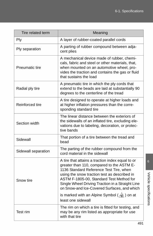
491
6-1. Specifications
6
Vehicle specifications
Tire related term Meaning
Ply A layer of rubber-coated parallel cords
Ply separation A parting of rubber compound between adja-cent plies
Pneumatic tire
A mechanical device made of rubber, chemi-cals, fabric and steel or other materials, that, when mounted on an automotive wheel, pro-vides the traction and contains the gas or fluid that sustains the load
Radial ply tireA pneumatic tire in which the ply cords that extend to the beads are laid at substantially 90 degrees to the centerline of the tread
Reinforced tire A tire designed to operate at higher loads and at higher inflation pressures than the corre-sponding standard tire
Section width
The linear distance between the exteriors of the sidewalls of an inflated tire, excluding ele-vations due to labeling, decoration, or protec-tive bands
Sidewall That portion of a tire between the tread and bead
Sidewall separation The parting of the rubber compound from the cord material in the sidewall
Snow tire
A tire that attains a traction index equal to or greater than 110, compared to the ASTM E- 1136 Standard Reference Test Tire, when using the snow traction test as described in ASTM F-1805-00, Standard Test Method for Single Wheel Driving Traction in a Straight Line on Snow-and Ice-Covered Surfaces, and which
is marked with an Alpine Symbol ( ) on at least one sidewall
Test rimThe rim on which a tire is fitted for testing, and may be any rim listed as appropriate for use with that tire

492
6-1. Specifications
*: Table 1 ⎯ Occupant loading and distribution for vehicle normal loadfor various designated seating capacities
Tire related term Meaning
Tread That portion of a tire that comes into contact with the road
Tread rib A tread section running circumferentially around a tire
Tread separation Pulling away of the tread from the tire carcass
Treadwear indicators (TWI)
The projections within the principal grooves designed to give a visual indication of the degrees of wear of the tread
Wheel-holding fixture The fixture used to hold the wheel and tire assembly securely during testing
Designated seating capacity, Number of
occupants
Vehicle normal load, Number of occupants
Occupant distribution in a normally loaded vehi-
cle
2 through 4 2 2 in front
5 through 10 3 2 in front, 1 in second seat
11 through 15 52 in front, 1 in second seat, 1 in third seat, 1
in fourth seat
16 through 20 72 in front, 2 in second seat, 2 in third seat, 1
in fourth seat

493
6
Vehicle specifications
6-2. Customization
Customizable features
Customizable Features
Vehicles with a Display Audio system: Settings that can bechanged using the Display Audio system(For further information on customizing settings using the DisplayAudio system, refer to the “Display Audio System Owner’s Man-ual”.)Vehicles with a navigation system: Settings that can be changedusing the navigation system(For further information on customizing settings using the naviga-tion system, refer to the “Navigation System Owner’s Manual”.)Settings that can be changed by your Toyota dealer
Definition of symbols: O = Available, — = Not available
Your vehicle includes a variety of electronic features that can be per-sonalized to suit your preferences. Programming these preferencesrequires specialized equipment and may be performed by yourToyota dealer.
Some function settings are changed simultaneously with other functionsbeing customized. Contact your Toyota dealer for further details.

494
6-2. Customization
Item Function Default set-ting
Customizedsetting
Smart key system*1 and wire-less remote control (→P. 32, 46)
Operation sig-nal (Emergency flashers)
On Off — O O
Operation sig-nal(Buzzer)
On Off — — O
Operation buzzer volume Level 5 Off to level 7 O O O
Time elapsed before auto-matic door lock function is acti-vated if door is not opened after being unlocked
60 seconds
Off
— O O30 seconds
120 seconds
Open door warning buzzer On Off — — O
Smart key system*1 (→P. 32)
Smart key sys-tem On Off — — O
Number of per-missible times of continuous smart lock
Twice Unlimited — — O

495
6-2. Customization
6
Vehicle specifications
Wireless remote control (→P. 46)
Wireless remote control On Off — — O
Unlocking operation
Driver's door unlocked in one step, all
doors unlocked in two steps
All doors unlocked in one step.
O O O
Panic function On Off — — O
Trunk unlock-ing operation
Press and hold (short)
Off
— — O
Press twice
One short press
Press and hold (long)
Item Function Default set-ting
Customizedsetting

496
6-2. Customization
Door lock (→P. 52)
Unlocking using a key
Driver's door unlocked in one step, all
doors unlocked in two steps
All doors unlocked in one step.
— O O
Speed-detect-ing automatic door lock func-tion
Off On O O O
Opening driver's door unlocks all doors
Off On — O O
Shifting gears to P unlocks all doors.
On Off O O O
Shifting gears to position other than P locks all doors.
On Off O O O
Automatic light con-trol sys-tem*1 (→P. 185)
Light sensor sensitivity Level 3 Level 1 to 5 O O O
Time elapsed before head-lights automati-cally turn off after doors are closed
30 seconds
0 seconds
O O O60 seconds
90 seconds
Lights (→P. 185)
Daytime run-ning light sys-tem (except Canada)
On Off O O O
Item Function Default set-ting
Customizedsetting

497
6-2. Customization
6
Vehicle specifications
Illumination(→P. 285)
Time elapsed before lights turn off
15 seconds
Off
— O O7.5 seconds
30 seconds
Operation when the doors are unlocked
On Off — — O
Vehicles with-out smart key system: Opera-tion after the engine switch turned to the “LOCK” posi-tionVehicles with smart key sys-tem: Operation after the “ENGINE START STOP” switch turned off
On Off — — O
Operation when you approach the vehicle with the electronic key on your per-son*2
On Off — — O
Seat belt reminder(→P. 423)
Vehicle speed linked seat belt reminder buzzer
On Off — — O
Item Function Default set-ting
Customizedsetting

498
6-2. Customization
*1: If equipped
*2: Vehicles with a smart key system
Automatic air condi-tioning sys-tem*1 (→P. 233)
Switching between out-side air and recirculated air mode linked to “AUTO” switch operation
Auto Manual — O O
A/C auto switch operation Auto Manual — O O
Power win-dow (driver’s door) & moon roof*1 (→P. 81, 84)
Key linked opening Off On — — O
Wireless remote control linked opening
Off On — — O
Key linked clos-ing Off On — — O
Wireless remote control linked opening buzzer
On Off — — O
Moon roof*1 (→P. 84)
Linked opera-tion of compo-nents when door key is used
Slide only Tilt only — — O
Linked opera-tion of compo-nents when wireless remote control is used
Slide only Tilt only — — O
Item Function Default set-ting
Customizedsetting

499
6
Vehicle specifications
6-3. Initialization
Items to initialize
Item When to initialize Reference
Maintenance data After the maintenance is performed P. 340
Tire pressure warning system (U.S.A. only)
• When changing tire pressure (such as when changing traveling speed, load weight, etc.)
• When changing the tire size
P. 368
The following items must be initialized for normal system operationafter such cases as the battery being reconnected, or maintenancebeing performed on the vehicle:

500
6-3. Initialization

502
Reporting safety defects for U.S. owners
If you believe that your vehicle has a defect which could cause acrash or could cause injury or death, you should immediatelyinform the National Highway Traffic Safety Administration (NHTSA)in addition to notifying Toyota Motor Sales, U.S.A., Inc. (Toll-free:1-800-331-4331).
If NHTSA receives similar complaints, it may open an investigation,and if it finds that a safety defect exists in a group of vehicles, itmay order a recall and remedy campaign. However, NHTSA can-not become involved in individual problems between you, yourdealer, or Toyota Motor Sales, U.S.A., Inc.
To contact NHTSA, you may call the Vehicle Safety Hotlinetoll-free at 1-888-327-4236 (TTY: 1-800-424-9153); go tohttp://www.safercar.gov; or write to: Administrator, NHTSA,1200 New Jersey Ave, S.E., Washington, DC 20590. You canalso obtain other information about motor vehicle safety fromhttp://www.safercar.gov.

503
7
For owners
Seat belt instructions for Canadian owners (in French)
The following is a French explanation of seat belt instructionsextracted from the seat belt section in this manual.
See the seat belt section for more detailed seat belt instructions inEnglish.
Utilisation correcte des ceintures de sécurité
● Tendez la sangle diagonale desorte qu'elle couvrecomplètement l'épaule, sansentrer en contact avec le couou glisser de l'épaule.
● Placez la sangle abdominalele plus bas possible sur leshanches.
● Réglez la position du dossierde siège. Asseyez-vous le dosle plus droit possible et calez-vous bien dans le siège.
● Ne vrillez pas la ceinture desécurité.

504
Entretien et soin
■Ceintures de sécurité
Nettoyez avec un chiffon ou une éponge humectée d'eau savonneuse tiède.Profitez de l'occasion pour vérifier régulièrement que les ceintures ne sontpas effilochées, entaillées, ou ne paraissent pas exagérément usées.
■Ceinture de sécurité arrière
ATTENTION
■Détérioration et usure des ceintures de sécurité
Inspectez les ceintures de sécurité périodiquement. Contrôlez qu'elles nesont pas entaillées, effilochées, et que leurs ancrages ne sont pasdesserrés. N'utilisez pas une ceinture de sécurité défectueuse avant qu'ellene soit remplacée. Une ceinture de sécurité défectueuse n'apporte aucunegarantie de protection de l'occupant en cas d'accident.
Si la ceinture de sécurité est sortie de songuide, repassez-la dedans avant del'utiliser.

505
7
For owners
SRS airbag instructions for Canadian owners (in French)
The following is a French explanation of SRS airbag instructions
extracted from the SRS airbag section in this manual.
See the SRS airbag section for more detailed SRS airbag instruc-
tions in English.
Sacs de sécurité gonflables SRS frontaux
Sac de sécurité gonflable conducteur/sac de sécurité gonflablepassager avant SRSParticipent à la protection de la tête et du thorax du conducteuret du passager avant contre les chocs avec les éléments del'habitacle
Sacs de sécurité gonflables SRS de genouxParticipent à la protection du conducteur et du passager avant

506
Sacs de sécurité gonflables SRS latéraux et rideau
Sacs de sécurité gonflables SRS latéraux avantParticipent à la protection du haut du corps des occupants assisaux places avant
Sacs de sécurité gonflables SRS latéraux arrièreParticipent à la protection du haut du corps des occupants assisaux places arrière extérieures
Sacs de sécurité gonflables SRS rideauParticipent principalement à la protection de la tête desoccupants assis aux places extérieures

507
7
For owners
Composition du système de sacs de sécurité gonflables SRS
Capteurs d'impact avant
Système de classificationdes occupants du siègepassager avant (ECU etcapteurs)
Sac de sécurité gonflablede genoux
Capteurs d'impact latéral(porte avant)
Capteurs d'impact latéral(avant)
Sac de sécurité gonflablepassager avant
Sacs de sécurité gonflableslatéraux avant
Sacs de sécurité gonflablesrideau
Sacs de sécurité gonflableslatéraux arrière
Témoins indicateurs “AIRBAG ON” et “AIR BAGOFF”
Témoin d'alerte SRS
Contacteur de boucle deceinture de sécuritépassager avant
Boîtier électronique de sacsde sécurité gonflables
Capteurs d'impact latéral(arrière)
Sac de sécurité gonflableconducteur
Contacteur de boucle deceinture de sécuritéconducteur
Prétensionneurs deceintures de sécurité etlimiteurs de force

508
Votre véhicule est équipé de SACS DE SECURITE GONFLABLESINTELLIGENTS (ADVANCED AIRBAGS) conçus selon les normesde sécurité américaines applicables aux véhicules à moteur(FMVSS208). Le boîtier électronique (ECU) des sacs de sécuritégonflables régule le déploiement de ces derniers sur la base desinformations qu'il reçoit des capteurs, etc., indiqués ci-dessus dans leschéma illustrant la composition du système. Parmi ces informationsfigurent la gravité du choc et l'occupation du véhicule par lespassagers. Le déploiement rapide des sacs de sécurité gonflablesest obtenu au moyen d'une réaction chimique dans les dispositifspyrotechniques, qui produit un gaz inoffensif permettant d'amortir lemouvement des occupants.

509
7
For owners
ATTENTION
■Précautions avec les sacs de sécurité gonflables SRS
Respectez les précautions suivantes concernant les sacs de sécuritégonflables SRS. À défaut, des blessures graves, voire mortelles, pourraient s'ensuivre.
●Le conducteur et tous les passagers à bord du véhicule doivent porter leurceinture de sécurité correctement.Les sacs de sécurité gonflables SRS sont des dispositifs de protectioncomplémentaires aux ceintures de sécurité.
●Le sac de sécurité gonflable SRS conducteur se déploie avec uneviolence considérable, qui peut être très dangereuse voire mortelle si leconducteur se trouve très près du sac de sécurité gonflable.L'autorité fédérale chargée de la sécurité routière aux États-Unis, laNHTSA (National Highway Traffic Safety Administration) conseille:
Sachant que la zone à risque du sac de sécurité gonflable conducteur setrouve dans les premiers 2 à 3 in. (50 - 75 mm) de déploiement, vousdisposez d'une marge de sécurité confortable en vous plaçant à 10 in.(250 mm) de votre sac de sécurité gonflable conducteur. Cette distanceest à mesurer entre le moyeu du volant de direction et le sternum. Si vousêtes assis à moins de 10 in. (250 mm), vous pouvez changer votreposition de conduite de plusieurs façons:
• Reculez votre siège le plus possible, tout en continuant à pouvoiratteindre confortablement les pédales.
• Inclinez légèrement le dossier du siège. Bien que les véhicules puissent être différents les uns des autres, laplupart des conducteurs peuvent s'asseoir à une distance de 10 in.(250 mm), même avec le siège conducteur complètement avancé,simplement en inclinant un peu le dossier de siège. Si vous avez desdifficultés à voir la route après avoir incliné votre siège, utilisez uncoussin ferme et antidérapant pour vous rehausser ou, si votrevéhicule est équipé du réglage en hauteur du siège, remontez-le.
• Si votre volant de direction est réglable, inclinez-le vers le bas. Cela apour effet d'orienter le sac de sécurité gonflable en direction de votrepoitrine plutôt que de votre tête et de votre cou.
Réglez votre siège selon ces recommandations de la NHTSA, tout enconservant le contrôle des pédales et du volant de direction, et la vue descommandes du tableau de bord.

510
ATTENTION
■Précautions avec les sacs de sécurité gonflables SRS
●Le sac de sécurité gonflable SRS passager avant se déploie égalementavec une violence considérable, qui peut être très dangereuse voiremortelle si le passager avant se trouve très près du sac de sécuritégonflable. Éloignez le siège passager avant au maximum du sac desécurité gonflable, et réglez le dossier de siège de sorte à être assis biendroit dans le siège.
●Les nourrissons et les enfants qui ne sont pas correctement assis et/ouprotégés peuvent être grièvement blessés ou tués par le déploiement d'unsac de sécurité gonflable. Installez dans un siège de sécurité enfant lesenfants trop jeunes pour pouvoir utiliser la ceinture de sécurité. Toyotarecommande vivement que les nourrissons et les jeunes enfants soientinstallés sur le siège arrière du véhicule et convenablement attachés. Lessièges arrière sont plus sûrs pour les nourrissons et les enfants que lesiège passager avant.
●Si vous attachez une rallonge deceinture de sécurité aux boucles deceinture de sécurité avant, mais pas aupêne de la ceinture de sécurité, lessacs de sécurité gonflables SRSfrontaux détectent que le conducteur etle passager avant ont attaché leurceinture de sécurité, alors même quece n'est pas le cas. Dans ce cas, il sepeut que les sacs de sécuritégonflables SRS frontaux ne sedéploient pas correctement en casd'accident, et vous risquez d'être tué ougrièvement blessé. Veillez donc àporter la ceinture de sécurité avec larallonge de ceinture de sécurité.

511
7
For owners
ATTENTION
■Précautions avec les sacs de sécurité gonflables SRS
●N'installez jamais un siège de sécurité enfant type dos à la route sur lesiège passager avant, même si le témoin indicateur “AIR BAG OFF” estallumé. En cas d'accident, par la violence et la vitesse de sondéploiement, le sac de sécurité gonflable passager avant peut blessergrièvement, voire tuer l'enfant si vous l'avez installé à la place du passageravant dans un siège de sécurité enfant type dos à la route.
●Ne pas s'asseoir sur le bord du siège etne pas s'appuyer contre la planche debord.
●Ne laissez pas un enfant rester deboutdevant le sac de sécurité gonflableSRS passager avant ou bien s'asseoirsur les genoux du passager avant.
●Ne laissez pas les occupants dessièges avant voyager avec un objet surles genoux.
●Ne vous appuyez pas contre la porte,contre le rail latéral de toit ou contre lesmontants avant, latéraux et arrière.

512
ATTENTION
■Précautions avec les sacs de sécurité gonflables SRS
● Interdisez à quiconque de s'agenouillersur les sièges passagers en appuicontre la porte ou de sortir la tête ou lesmains à l'extérieur du véhicule.
●Ne fixez ni ne posez aucun objet sur laplanche de bord, la garniture centraledu moyeu de volant de direction et lapartie inférieure du tableau de bord. Au déploiement des sacs de sécuritégonflables SRS conducteur, passageravant et genoux, tout objet risque de setransformer en projectile.
●Ne rien fixer aux portes, à la vitre depare-brise, aux vitres latérales, auxmontants avant et arrière, au rail latéralde toit et à la poignée de maintien.
●Véhicules dépourvus de systèmed'accès et de démarrage “mains libres”:Évitez d'attacher au porte-clés de la cléde contact des objets lourds, pointus outrès durs, comme d'autres clés parexemple. Ces objets risquent d'entraverle déploiement du sac de sécuritégonflable SRS de genoux ou d'êtreprojetés vers le siège conducteur par laforce de déploiement, constituant ainsiun danger potentiel.

513
7
For owners
ATTENTION
■Précautions avec les sacs de sécurité gonflables SRS
●Ne suspendez aux crochets à vêtements aucun cintre nu ni aucun objetdur. En cas de déploiement des sacs de sécurité gonflables rideau SRS,tous ces objets pourraient se transformer en projectiles et causer desblessures graves, voire mortelles.
●Si une housse en vinyle recouvre la partie où le sac de sécurité gonflableSRS de genoux se déploie, veillez à l'enlever.
●N'utilisez aucun accessoire de siège venant recouvrir les zones dedéploiement des sacs de sécurité gonflables SRS latéraux, car il risqueraitd'en gêner le déploiement. De tels accessoires peuvent empêcher lessacs de sécurité gonflables latéraux de fonctionner correctement,désactiver le dispositif ou entraîner le déploiement accidentel des sacs desécurité latéraux, entraînant la mort ou des blessures graves.
●Évitez de faire subir des chocs ou des pressions excessives aux zonesrenfermant les composants des sacs de sécurité gonflables SRS. En effet, cela pourrait entraîner un fonctionnement anormal des sacs desécurité gonflables SRS.
●Ne touchez aucun composant du système immédiatement après ledéclenchement (déploiement) des sacs de sécurité gonflables SRS, car ilssont alors encore très chauds.
●Si vous avez des difficultés à respirer après le déploiement des sacs desécurité gonflables SRS, ouvrez une porte ou une vitre pour faire entrer del'air frais, ou bien descendez du véhicule si cela ne présente pas dedanger. Essuyez tout résidu dès que possible afin d'éviter d'éventuellesirritations de la peau.
●Si les parties renfermant les sacs de sécurité gonflables SRS, telles que lagarniture du moyeu de volant et les garnitures de montants avant etarrière, apparaissent abîmées ou craquelées, faites-les remplacer parvotre concessionnaire Toyota.

514
ATTENTION
■Modification et mise au rebut des éléments du système de sacs de
sécurité gonflables SRS
Consultez impérativement votre concessionnaire Toyota si vous avez besoind'intervenir sur votre véhicule ou de procéder à l'une des modificationssuivantes. Les sacs de sécurité gonflables SRS risquent de ne pasfonctionner correctement ou de se déployer (gonfler) accidentellement,provoquant ainsi des blessures graves, voire mortelles.
● Installation, dépose, démontage et réparations des sacs de sécuritégonflables SRS
●Réparations, modifications, démontage ou remplacement du volant, dutableau de bord, de la planche de bord, des sièges ou de leur garnissage,des montants avant, latéraux et arrière ou des rails latéraux de toit
●Réparations ou modifications des ailes avant, du bouclier avant, ou desflancs de l'habitacle
● Installation de chasse-neige, de treuils, etc., sur la calandre (pare-buffleou pare-kangourou, etc.)
●Modification des suspensions du véhicule
● Installation d'appareils électroniques, tels qu'un radioémetteur/récepteurou d'un lecteur CD
●Aménagements du véhicule visant à permettre sa conduite par unepersonne atteinte d'un handicap physique

528
What to do if...
What to do if...
A tire punctures P. 435 If you have a flat tire
The engine does not start
P. 447 If the engine will not startP. 92 Engine immobilizer system
P. 454 If the battery is discharged
P. 451If the electronic key does not oper-ate properly
The shift lever cannot be moved out
P. 449If the shift lever cannot be shifted from P
The rightmost segment of the engine coolant temperature display flashes
Steam can be seen coming from under the hood
P. 459 If your vehicle overheats
The key is lost P. 450 If you lose your keys
The battery runs out P. 454 If the battery is discharged
The doors cannot be locked P. 52 Doors
The horn begins to sound P. 95 Alarm
The vehicle is stuck in mud or sand
P. 462 If the vehicle becomes stuck

529
What to do if...
A warning light or indicator light comes on
P. 420If a warning light turns on or a warning buzzer sounds...
Type A
Type B

530
What to do if...
■Warning lights
P. 421or
P. 420 P. 421
P. 421 P. 423
P. 421 P. 423
P. 423or
P. 421 P. 423
P. 421 P. 423
P. 421or
P. 421 P. 421
Brake system warning light
Cruise control indicator light*1
Slip indicator light
Charging system warn-ing light
Tire pressure warning light
Low engine oil pressure warning light
Low windshield washer fluid warning light
Malfunction indicator lamp
Open door warning light
Low fuel level warning light
SRS warning light Driver’s/front passenger’s seat belt reminder light
ABS warning light Electric power steering sys-tem warning light
BSM warning light

531
What to do if...
P. 423 P. 421
or
P. 421
*1: The light comes on in yellow to indicate a malfunction.*2: The light flashes in yellow to indicate a malfunction. The light flashes
quickly in green to indicate that the steering lock has not been released.
Maintenance required reminder light
Smart key system indi-cator light*2
High engine cool-ant temperature warning light (the rightmost seg-ment of the engine coolant tempera-ture display flashes)

532
GAS STATION INFORMATION
Auxiliary catch leverP. 350
Trunk openerP. 58
Fuel filler doorP. 88
Hood lock release leverP. 350
Fuel filler door openerP. 88
Tire inflation pressureP. 474
Fuel tank capacity(Reference) 17.0 gal. (64.35 L, 14.2 Imp. gal.)
Fuel type Unleaded gasoline only P. 468Cold tire inflation pressure P. 474
Engine oil capacity (Drain and refill ⎯ reference)
2.5 L 4-cyl-inder (2AR-FE) engine
qt. (L, Imp. qt.)With filter 4.6 (4.4, 3.9)Without filter 4.2 (4.0, 3.5)
3.5 L V6 (2GR-FE) engine
With filter 6.4 (6.1, 5.4)Without filter 6.0 (5.7, 5.0)
Engine oil type P. 469