Fictional Creature Propagates Reality Undergraduate Thesis by David J Pearson
2012 NSF Final Report
Crack path selection in mixed mode fracture tests of adhesive bonds, including those with locally weakened interfaces
Adhesives offer many advantages over discrete mechanical fasteners such as bolts and rivets. By eliminating the holes or other mechanical fasteners, components may often be made thinner that will save weight, time, and costs. Because adhesives are often applied continuously and efficiently with robots, they can seal out corrosive liquids such as saltwater to improve structural durability, and significantly improve the torsional and bending stiffness of parts in automobiles.
However, there are still many challenges such as the hidden cracks and damages in the adhesives to be resolved. This project aimed at delineating the mechanics of failure adhesively bonded joints under complex loading. Furthermore, this work provides additional insights into the crack path selection in adhesively bonded joints as well as the variation in the adhesive thickness along the bonded surfaces. It is anticipated that this information will be important in the design of bonded joints, the estimation of their working life, and durability of the adhesively bonded components in automobiles, airplanes, and other industrial components.
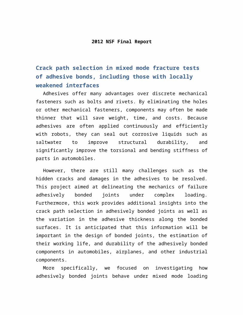
More specifically, we focused on investigating how adhesively bonded joints behave under mixed mode loading conditions, interaction between cracks or between crack and weakened areas, etc. Weak interfaces between the adhesive and the adherend were generated by either treating the adherend surface with a chemical such as silane or contaminating it with graphite particles. The surface treatments are schematically shown in Fig. 1.
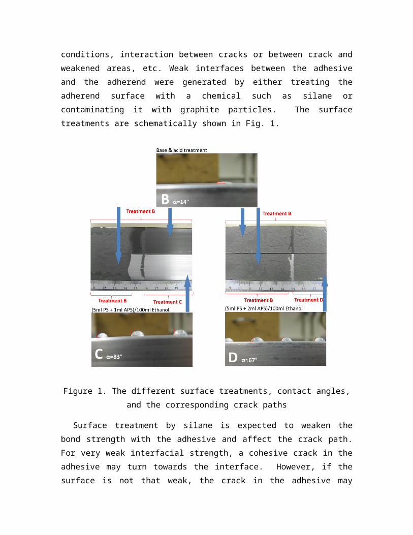
Figure 1. The different surface treatments, contact angles, and the corresponding crack paths
Surface treatment by silane is expected to weaken the bond strength with the adhesive and affect the crack path. For very weak interfacial strength, a cohesive crack in the adhesive may turn towards the interface. However, if the surface is not that weak, the crack in the adhesive may ignore the weak surfaces and remain in the adhesive when in pure opening mode. The contact angle between the water drop and the aluminum beam surface was used to estimate the bonding strength: smaller angle meant stronger bonding strength and higher surface energy. We note that when the contact angle changed from 67° to 83°, different crack paths were found during mode-I or pure opening of the joint.
Other surface modifications, such as contamination, were also studied. The contaminant covered the surface and interrupted bonding between the aluminum beam and the adhesive. Though the mechanism of this weakening is still unclear, crack paths were found to be rate dependent in several tests with different crosshead displacement rates; e.g. see Figure 2. It was found that at relatively high loading rate, the contaminated interfaces were recognized by the main crack propagating within the adhesive layer, and

there was strong evidence of stick and slip phenomenon on the failure surfaces. However, at slow loading rates, around 1mm/min in our tests, weak interfaces were essentially ignored by the main cracks and crack propagation was stable.
Figure 2. Effect of loading rate on crack path selection in bonded joints with interfaces contaminated with graphite.
The aforementioned experimental work was complemented with mathematical and computational models of the bonded joints. We note that computational experiments can replace physical tests since they are inexpensive. Validated numerical simulations have predictive capabilities not generally available in physical experiments. The collaboration between the modeling and experimental efforts can provide new insights into fracture behavior afforded through the synergistic interactions, with modeling needs suggesting experiments to perform and experiments identifying and quantifying phenomena to be studied.
An efficient meshless method has been developed for analyzing crack propagation in adhesively bonded joints and has been applied to study the failure of double cantilever beam (DCB) specimens subjected to single or mixed mode loading conditions. Advantages of a meshless method include not having to generate nodal connectivity, and the ease with which particles can be added and deleted within the domain of study. Furthermore, the crack path as dictated by the physics of the problem can be found since the crack is not required to propagate along the interface between two elements. A comparison of the traditional finite element method (FEM) and a meshless method for studying crack propagation is illustrated in Fig. 3.

Figure 3. The difference between meshless method and traditional FEM method.
Add particles
FEM
Must remesh
Meshless
New meshNew crack tipOld crack tip & mesh

In Figure 4, results of numerical analysis of the problem with weak interfaces are presented. It is assumed that a crack propagates in the direction for which the principal stress reaches a material dependent critical value. The debonding at the interface between the adhesive and the adherend is simulated by using the cohesive zone model that describes material separation with a traction-separation law, and assumes that the contacting surfaces have completely separated when the area under the traction-separation curve equals the critical fracture energy.
-0.25
-0.20
-0.15
-0.10
-0.05
0.00
0.05
0.10
0.15
0.20
0.25
56.5 57.0 57.5 58.0 58.5 59.0 59.5 60.0 60.5 61.0
y-co
ordi
nate
(mm
)
x-coordinate (mm)
Crack path (Mode I)
Crack path (Mode II)
-0.25
-0.20
-0.15
-0.10
-0.05
0.00
0.05
0.10
0.15
0.20
0.25
56.5 57.0 57.5 58.0 58.5 59.0 59.5 60.0 60.5 61.0
y-coor
dina
te (m
m)
x-coordinate (mm)
Crack path (Mode I)
Crack path (Mode II)
-0.25
-0.20
-0.15
-0.10
-0.05
0.00
0.05
0.10
0.15
0.20
0.25
56.5 57.0 57.5 58.0 58.5 59.0 59.5 60.0 60.5 61.0
y-coordinate (mm)
x-coordinate (mm)
Crack path (Mode I)
Crack path (Mode II)
Weak zone region
Blue curve: Very weak interface
Red curve: Moderately weak interface

-0.25
-0.20
-0.15
-0.10
-0.05
0.00
0.05
0.10
0.15
0.20
0.25
58 59 60 61 62 63 64
y-co
ordi
nate
(mm
)
x-coordinate (mm)
-0.25
-0.20
-0.15
-0.10
-0.05
0.00
0.05
0.10
0.15
0.20
0.25
57.5 58.0 58.5 59.0
y-co
ordi
nate
(mm
)
x-coordinate (mm)
Cohesive zone modelδ
δ
Initial crack (ac)Adhesive
Adherend
Adherend
Principal stress
Delamination region
Traction (MPa)
Relative displacement (mm)
Dissipated energy
Figure 4. Schematics of simulation of crack initiation and propagation in adhesively bonded joints with weak interfaces

Development of a combinatorial specimen configuration to evaluate effect of adhesive thickness on fracture energy of bonded joints
Fracture energies of adhesive bonds have been shown to depend significantly on the
thickness of the adhesive bondlines in many situations. Although bondline thicknesses
are often carefully controlled in aerospace applications of structural adhesives, these
bondline thicknesses can vary more dramatically in automotive applications and much
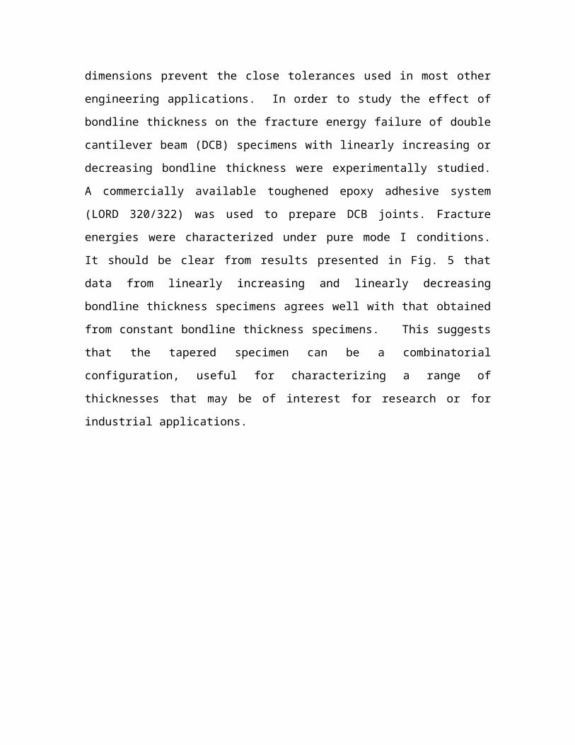
more so in the assembly of wind turbine blades, where the large dimensions prevent the
close tolerances used in most other engineering applications. In order to study the effect
of bondline thickness on the fracture energy failure of double cantilever beam (DCB)
specimens with linearly increasing or decreasing bondline thickness were experimentally
studied. A commercially available toughened epoxy adhesive system (LORD 320/322)
was used to prepare DCB joints. Fracture energies were characterized under pure mode I
conditions. It should be clear from results presented in Fig. 5 that data from linearly
increasing and linearly decreasing bondline thickness specimens agrees well with that
obtained from constant bondline thickness specimens. This suggests that the tapered
specimen can be a combinatorial configuration, useful for characterizing a range of
thicknesses that may be of interest for research or for industrial applications.
0 0.5 1 1.5 2 2.5 3 3.5 4 4.5 5 5.5 6 6.50
200
400
600
800
1000
1200
1400
Increasing thickness (0.1mm to 0.75mm)Increasing thickness (0.87mm to 2.35mm)Increasing thickness (1mm to 4mm)Increasing Thickness (2.77mm to 5.51mm)Decreasing thickness( 5mm to 1.36)Decreasing thickness (4mm to 1mm)Decreasing thickness (2.16mm to 0.88mm)Decreasing thickness (0.75mm to 0.1mm)0.02mm constant thickness0.77mm constant thickness1.87mm constant thickness1.7mm constant thickness2.26mm constant thickness4.52mm constant thickness
Bondline thickness, h (mm)
GIc
(J/m
2)
Figure 5: Comparison of variation in the mode I fracture energy with bondline thickness
between specimens with the constant bondline thickness and specimens with linearly
increasing and decreasing bondline thickness specimens
Reconsidering interpretations of the T-peel specimenT-peel test specimen behavior and test results depend on strongly on the specific configuration the specimen assumes during testing. To illustrate the range of behavior and data that can be obtained, a series of T-peel tests were conducted using three types of steels and an aluminum alloy as adherends. These were bonded with two kinds of acrylic adhesives. For the same adhesive, effects of the adherend material and thickness on T-peel test results are investigated. After curing at room temperature for 4 days, the bent tabs of the specimens were held by the grips of an Instron testing machine, and were pulled at 51mm/min at room temperature, the peel forces versus crosshead displacement curves were recorded during the peel process. Six replicate specimens were used. From
Figures 6 to 11 we can see that the adherend thickness, modulus, and yield properties, the adhesion properties can strongly influence the T peel test behavior.
The finite element method (as seen in figure 10, 11) is employed to subtract the calculated plastic dissipation from the measure peel energy, resulting in extraction of meaningful fracture energy. A cohesive element technology that is implemented in the Abaqus is used to investigate fracture of adhesive joints. The geometric dimensions, materials and boundary equations used in the FEM are the same as that in the experiments. As seen in Figures 12 and 13, these predictions show excellent agreement with experimental observations. Comparing with the experimental results, the numerical calculations quantitatively catch the features of the deformation, and show that T-peel tests can result in highly exaggerated fracture energy unless careful analysis is conducted to subtract the energy involved in deforming adherend plastically from the apparent peeling energy.
This study has provided new insights into the T-peel configuration. Specifically, four different categories have been identified, each with its own specific analysis method. The commonly reported metric for the test method, the peel strength, is prescribed by standards developed for this test method, and defined as the average load measured during crosshead separation. We demonstrate how this metric may not be appropriate for certain categories of these test configurations, and suggest alternative interpretations.
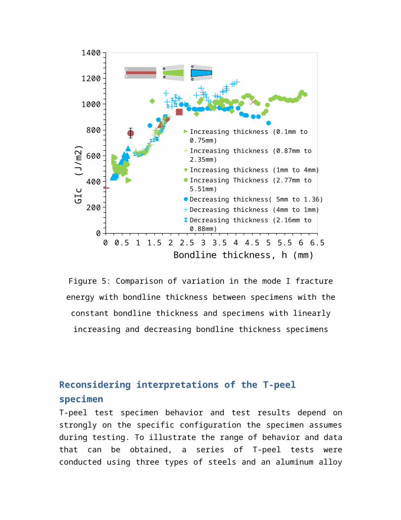
Figure 6, 7 Comparison of the deformed shapes of specimens with different adherends
CRS
Aluminum
EGZHDG
Adhesive: Acrylic #1
CRS
Aluminum
EGZHDG
Adhesive: Acrylic #2
Figure 8, 9 Comparison of the deformed shapes of specimens with different thickness of adherend
Adherend: AluminumAdhesive: Acrylic #1
Thickness: 1.6mm Thickness: 0.8mm Thickness: 1.6mm Thickness: 0.8mm
Adherend: AluminumAdhesive: Acrylic #2

Figure 10, 11 stress distributions of the specimen during peel process
Adherend: EGZAdhesive: Acrylic #2
Adherend: AluminumAdhesive: Acrylic #2

Figure 12, 13 Comparison of the deformed shapes between T-peel test results and computed results
FEM resultsEGZ: experimental results FEM resultsAluminum: experimental results