2012 Getting Started Guide - Vectorworks
72
Renderworks 2012 Getting Started Guide | 1 2012 Getting Started Guide The contents of this guide and accompanying exercises were originally created for Nemetschek Vectorworks, Inc. by Daniel Jansenson.
Transcript of 2012 Getting Started Guide - Vectorworks

Renderworks 2012 Getting Started Guide | 1
2012 Getting Started Guide
The contents of this guide and accompanying exercises were originally created for Nemetschek Vectorworks, Inc. by Daniel Jansenson.

2 | Renderworks 2012 Getting Started Guide
© 2011 Nemetschek Vectorworks, Inc.
All rights reserved. No part of this book may be reproduced or transmitted in any form by any means, electronic or mechanical, including photocopying, recording, faxing, emailing, posting online or by any information storage and retrieval system, without prior written permission of the publisher. Published in the United States.
Vectorworks and Renderworks are registered trademarks of Nemetschek Vectorworks, Inc., in the United States and other countries. Windows is a registered trademark of Microsoft Corporation in the United States and other countries. Macintosh is a trademark of Apple Computer, Inc., registered in the United States and other countries. Adobe, Acrobat and Reader are registered trademarks of Adobe Systems in the United States and other countries.
The information in this book is distributed on an “as is” basis, without warranty. While every precaution has been taken in the preparation of this book, neither the author nor Nemetschek Vectorworks, Inc., shall have any liability to any person or entity with respect to any loss or damage caused or alleged to be caused directly or indirectly by the information contained in this book or by the computer software described in it.
For additional Vectorworks training information, or to purchase copies of this book, please call us, in the United States at (410) 290-5114 or visit Vectorworks.net/training online.
NVM.GSGRW-2012 v1.0

Renderworks 2012 Getting Started Guide | 3
Table of Contents
Introduction ...............................................................................................................5
Section 1: Exterior Building View............................................................................7 Task 1: Place Renderworks Cameras............................................................................ 9 A. Select the Renderworks Camera Tool .................................................................9
B. Place the first camera ..........................................................................................9
C. Adjust the camera’s height ................................................................................10
D. Save the view ....................................................................................................11
E. Place the second camera. .................................................................................11
F. Adjust the second camera’s height ...................................................................11
Task 2: Lighting & Light Quality Settings ....................................................................12
A. Place a Heliodon (sunlight) ................................................................................12
B. Adjust the light quality settings ..........................................................................13
1. Ambient lighting .........................................................................................14
2. Indirect lighting ..........................................................................................15
C. Add light from the sky ........................................................................................17
1. Set a HDRI background as a light source .................................................17
2. Select the desired HDRI background ........................................................18
Task 3: Apply Textures ..................................................................................................19
1. Landscaping. ......................................................................................................19
2. Hardscaping .......................................................................................................21
3. Building Walls .....................................................................................................25
4. Glass ..................................................................................................................30
Task 4: Add Sky .............................................................................................................33
Task 5: Add Entourage ..................................................................................................33

4 | Renderworks 2012 Getting Started Guide
1. Create and place image props ...........................................................................33 2. Place additional, premade image props .............................................................37 3. Place 3D symbols ..............................................................................................38 Task 6: Render and Export an Image ...........................................................................39 1. Render the scene (including Renderworks styles). ............................................39 2. Render a viewport ..............................................................................................42 3. Export the image. ...............................................................................................44
Section 2: Day-Time Interior View .........................................................................47 Task 1: Place a Heliodon Representing the Sun .........................................................48 Task 2: Lighting: Add Light from the Sky ....................................................................49 Task 3: Lighting: Set Lighting Options ........................................................................50 Task 4: Add a Graphic Sky Background ......................................................................50 Task 5: Create and Apply Textures ..............................................................................51 1. Rear wall ...........................................................................................................51 2. Mesh partition ....................................................................................................53 3. Wood paneling ...................................................................................................55 Task 6: Render using Custom Renderworks ..............................................................57
Section 3: Night-Time Interior View ......................................................................59 Task 1, Lighting: Place and Adjust Lights ...................................................................60 A. Rectangular fluorescents ...................................................................................60 B. Round, surface-mount fixtures ..........................................................................61 C. Pendant lights at reception counter ...................................................................63 D. Fluorescent pendant light over conference table ..............................................64 E. Rear signage at the mesh partition (in front of the stairs) ..................................65 1. Create the texture .....................................................................................66 2. Apply the new neon light texture to the 3-D model of the neon tubing ......67 Task 2: Lighting: Set the Appropriate Light Quality Settings ....................................67 Task 3: Render using Custom Renderworks ..............................................................68 Task 4: Adjust Custom Renderworks Settings to Control Brightness .....................69

Renderworks 2012 Getting Started Guide | 5
Introduction
Basic information about Renderworks can be found in a variety of places. These include third-party sources such as Jonathan Pickup’s Archoncad, this author’s own Remarkable Renderworks book, and a large repository of resources in Nemetschek Vectorworks’ own materials–including much excellent information in other Getting Started guides.
Kevin Lee Allen’s Spotlight Getting Started Guide has much valuable information about Renderworks. And Tamsin Slatter has prepared an excellent Renderworks Migration Hints and Tips guide that is a small manual in itself.
Familiarity with basic Renderworks techniques is one thing. Incorporating these basic skills into an overall rendering workflow is the next step, and is the basis of the material in this guide.
This book uses three case studies as the underpinning for detailed, step-by-step tutorials. There is no discussion of theory or high principles. Instead, the material uses an organized and logical method to develop each rendering exercise, from opening the file at the beginning, to exporting an image at the end. The intent is to convey the fundamental methods of texturing, lighting and rendering by describing the sequence of steps necessary to complete each rendering.

6 | Renderworks 2012 Getting Started Guide
Each section is divided into tasks, which are the organizing stepping stones of the process. Each task contains a number of sub-steps covering the details of texturing, lighting and rendering. A careful and methodical approach to these steps and tasks simplifies the process of preparing Renderworks renderings, and makes it easier to make adjustments and changes.

Renderworks 2012 Getting Started Guide | 7
Section 1:Exterior Building View A Vectorworks model is prepared for rendering using a three-step process. The sequential F/L/R workflow–File Prep/Lighting/Rendering–can consistently yield good-quality results when followed carefully and methodically. Note that the settings for lighting quality are completely
separate from those of rendering quality, even though they are closely linked. The workflow need not be completed in a specific order of tasks, necessarily (except for the last step), but it is important to view each step as a separate action–a stepping-stone, as it were, on the road to the final rendering.
This exercise will describe six basic sequential tasks, each adding a level of completion to the rendering:
1. Place Renderworks cameras.2. Arrange lights and light quality settings.3. Apply textures.4. Add a sky background.5. Add entourage.6. Render and export.
Open the file: building-new.vwx from the Exterior Building View folder. Take a quick first look.

8 | Renderworks 2012 Getting Started Guide
Make sure the entire model fits on the screen: -click on the Fit To Objects button in the View Bar. The view is in wireframe:
-Make a quick first rendering using OpenGL: View>Rendering>OpenGL. The white building in the middle of the screen is the subject of this rendering exercise. The large gray buildings around it are massing models intended for background purposes.
Note: OpenGL is a suitable rendering method when fast results are needed. Renderworks can provide higher-quality renderings, and will be discussed later in this chapter.
-Switch to Top/Plan view: View>Standard Views>Top/Plan.
-Change layer visibility to display the lower layer: View>Layer Options>Show/Snap Others.
The layer Entourage Locations is now visible. Zoom in and take note of the information shown on this layer.
Note: This exercise will create and use a variety of scene accessories–image props and cameras that will need to be placed in certain places on the drawing. The Entourage Locations layer displays those spots as a kind of map, showing the exact locations of the image props and cameras. When the information is no longer needed, we will make this layer invisible.

Renderworks 2012 Getting Started Guide | 9
Task 1: Place Renderworks Cameras. This exercise will use two Renderworks cameras to generate views that will be used in the renderings. One camera will show an overall view of the building’s front. The other camera will be oriented to display the building at an angle, and from a closer distance.
We will place the cameras in the layer Site With Buildings, which is currently active.
Before proceeding, zoom in to the area marked in the diagram. The two camera locations are in this area and can be seen more clearly from a closer distance.
A. Select the Renderworks Camera Tool.-In the Visualization Toolset, select the Renderworks Camera tool.
B. Place the first camera.-With the tool selected, click once in the center of the marker called Camera 1. Then drag the cursor in the direction of the marker’s arrow to set a direction, and click again to complete the action.
The Object Properties dialog box appears. Click OK.
To see what the camera sees, leave the camera object selected, go to the Object Info palette (under the Shape tab) and click on the Display Camera View button. The scene will swtich to a perspective view as seen by the camera. Can’t see the perspective view? Click on the Fit to Objects button in the View Bar.
Zoom to here

10 | Renderworks 2012 Getting Started Guide
Note: the Entourage Locations layer is still visible. Make it invisible by changing the Layer Options to Active Only: View>Layer Options>Active Only.
C. Adjust the camera’s height. -In the Object Info palette, click on the Fine Tune Camera View button. The Perspective View Controls dialog box opens. The first slider at the top is the Camera Height control. In the white data field, enter the height: 6’-0” [1830mm].
The camera is now tilting down slightly. To correct this, go to the Look To Height slider, and in the white data box enter the height: 6’-0” [1830mm]. Click OK.The camera’s actual height, and the direction in which it looks are now both the same, so the camera’s view is perfectly horizontal.
Is the image too small on the sheet? Is it off-center on the screen?
To make the image bigger on the sheet, go to the Object Info palette. With the camera object selected, go to the Clip Frame Scale % data box and enter 200. Then update the view: select the Auto Update 3D View checkbox near the bottom of the palette.
To center the image on the screen, select the Auto Center 3D View checkbox.

Renderworks 2012 Getting Started Guide | 11
Before saving this view, make sure the Entourage Locations layer is invisible: View>Layer Options>Active Layer Only.
D. Save the view.-View>Save View. The Save View dialog box opens. Give this view a name: View 1. Click OK.
E. Place the second camera. First make the Entourage Locations layer visible: View>Layer Options>Show/Snap Others.
-Switch to Top/Plan view and zoom in again to the area shown earlier. Note the location of the marker called Camera 2. In the Visualization palette, select the Renderworks Camera tool, and place a new camera in the center of the Camera 2 marker. Point, drag and click to finish as described earlier.
Note: The Object Properties dialog box didn’t open this time; it only opens the first time the Renderworks Camera tool is used in a file.
F. Adjust the second camera’s height. -With the camera selected, go to the Object
Info palette and click on the Fine Tune Camera View button. The Perspective View Controls dialog box opens. Change the Camera Height and Look To settings to 6’-0” [1830mm]. Click OK.
Make the Entourage Locations layer invisible (View>Layer Options>Active Only or change visibilities in the Organization dialog box), and then save this view as well, with the name View 2.
Note: We can access this camera’s view at any time by selecting it in the Saved Views drop-down box or double-clicking on the view in the Visualization palette. We can also access this camera’s view by going to Top/Plan view and double-clicking on the camera object itself, or by going to the Visualization palette and double-clicking on the camera there (click on the Cameras tab of the palette to display the cameras in the file).
Congratulations! We’ve completed the first task: placing cameras and saving views.

12 | Renderworks 2012 Getting Started Guide
Task 2: Lighting & Light Quality Settings This task will demonstrate a variety of lighting settings and propose a suitable combination for this exercise file.
In the Saved Views drop-down box, select View 2. The image on the screen will be in wireframe (not rendered).
First a quick first rendering in Renderworks:-View>Rendering>Fast Renderworks.
Wait a few seconds until the scene finishes rendering. Notice that the scene is lit, even though there are no actual light objects in the file. This is due to the default lighting provided
by the program, mainly for working purposes. Once lights are placed in the scene (including a Heliodon light representing the sun), the original default lighting is disabled and lights can be adjusted as desired, resulting in a better quality rendering.
Note: Does the scene look a little rough and unfinished? The Fast Renderworks setting is useful for on-going work, rather than final quality renderings, which can take a long time to complete. With this Renderworks setting, low-level accuracy, quality and resolution settings make for a speedy rendering, albeit at the expense of image quality. More on adjusting these settings later.
What light sources will we use?
The final lighting in this exterior scene will come from two sources:
• a Heliodon representing the sun;• a High Dynamic Range Image (HDRI)
background representing overall light coming from the sky.
A. Place a Heliodon (sunlight).Now add the first of two light sources used in this exercise: sunlight. The light of the sun is represented by a specific kind of light object: a Heliodon.
In the Tool Sets palette, click on the Visualization tool set, and double-click on the Heliodon tool.

Renderworks 2012 Getting Started Guide | 13
A Heliodon will be placed in the scene, and the Create Object dialog box will open.
Click on the Settings button. The Settings dialog box opens. Under Location, click on the Region drop-down box and select USA. Now click on the City drop-down box and select Los Angeles. Click OK.
Back in the Create Object dialog box, enter the following information:
Time: 9:30 AMDay: 20Month: February
Leave everything else as-is, and click OK. The Heliodon’s settings are complete for this scene.
With the sunlight in place, we will make adjustments to the light settings in order to improve the quality of the rendering.
B. Adjust the light quality settings.The scene’s light quality settings can dramatically affect the length of time required to complete a rendering. In this exercise we will first use light quality settings that yield quick renderings, using Ambient lighting.

14 | Renderworks 2012 Getting Started Guide
Then we will improve the light quality settings by adding Indirect lighting, but at the expense of longer renderings.
Before proceeding, open the Lighting Options dialog box (View>Lighting>Set Lighting Options) and take a look at the various components of the dialog box:
• The Indirect Lighting drop-down box controls lighting that bounces from one surface onto another. This is a feature that provides great realism. The greater the number of bounces, the more realistic the image–and the longer the rendering takes to complete.
• Ambient Info controls Ambient lighting, its brightness and color. Ambient lighting is general, sourceless lighting that affects all surfaces equally. This lighting can be used by itself, for general lighting purposes, or in combination with other light sources (such as light objects). It can also be used as a method of adding general light to a scene that has already been lit using other methods.
• Emitter Options sets the brightness and color temperature of light objects that have been set to Use Emitter (none of those are included in this exercise file).
• Environment Lighting (HDRI) provides access to Renderworks backgrounds that can be used for lighting purposes, as well as graphic representations of the sky. More on this later. Click OK to close the dialog box.
1. Ambient lightinga. For the first example, use only the
illumination produced by the Heliodon placed earlier–without Ambient lighting:-View>Lighting>Set Lighting Options.
The Lighting Options dialog box opens. From top to bottom, arrange the settings as shown in the image below and click OK.
-Now render in Fast Renderworks: View>Rendering>Fast Renderworks.
Note that the shadows are dark and lacking in detail. We can improve on this by adding Ambient lighting and changing the default settings.

Renderworks 2012 Getting Started Guide | 15
b. Add and adjust Ambient lighting:-View>Lighting>Set Lighting Options. The Lighting Options dialog box opens.-Under Ambient Info, click On.-Make sure the Brightness (%) box shows 35.
-Click OK and render in Fast Renderworks: View>Rendering>Fast Renderworks.c. For a smoother rendering, try rendering in Final Quality Renderworks.
2. Indirect LightingIn the second example, we will modify the light settings to include Indirect lighting.
This is a feature that provides much-improved realism by displaying lighting that bounces from one surface onto another. We will also turn off Ambient lighting in order to enhance the image’s quality.
a. Add Indirect lighting:
-View>Lighting>Set Lighting Options. The Lighting Options dialog box opens.
-Click on the Indirect Lighting drop-down box and select Exterior, 1 Bounce. Click OK.
Now render in Fast Renderworks: View>Rendering>Fast Renderworks.
Notice the increased rendering time compared to the previous light settings. More importantly, the effect of Indirect lighting can be seen clearly in places such as the left side of the entry area and the joint between the main building and the angled portion to the right.

16 | Renderworks 2012 Getting Started Guide
The image can be much improved by switching Ambient lighting off.
b. Remove Ambient lighting.
-View>Lighting>Set Lighting Options. The Lighting Options dialog box opens.
-Under Ambient Info, click Off.
-Click OK.
To see the full impact of the change, render in Final Quality Renderworks.
Note that with Ambient lighting turned off, the building’s entry area is now a bit dark. We can improve the rendering by increasing the number of Indirect Lighting bounces. This
will increase the quality and realism of rendered surfaces that bounce light from one to the next, including the area near the building’s entrance. Increasing the number of light bounces there will represent the bounced lighting more accurately.
c. Increase the number of Indirect Lighting bounces:-View>Lighting>Set Lighting Options. The Lighting Options dialog box opens.
-Click on the Indirect Lighting drop-down box and select Normal, 2 Bounces. Click OK.
The file will automatically rerender in Final Quality Renderworks. Note that this new quality setting will result in a longer render, requiring a wait before final results can be seen. If the wait is acceptable, we can obtain even better results by selecting Interior, 4 Bounces in the Indirect Lighting drop-down box, but this will result in a much lengthier render, and the results may not justify the increased rendering time:

Renderworks 2012 Getting Started Guide | 17
To recap: We first rendered the file using a Heliodon representing the sun. Then, to fill in the shadows, we added Ambient lighting. Finally, in order to improve the quality of the final rendered image, we switched off Ambient lighting, turned on Indirect lighting
and then increased the number of bounces. In each case the rendering was better; but at the expense of longer completion times.
We will now improve the quality of the rendering even further by adding one more source of light: the sky.
Before proceeding, render the file in Wireframe: View>Rendering>Wireframe.
C. Add light from the sky.In the real world the sun is not the only source of daytime exterior lighting. The atmosphere–or sky– itself is another. Think of the sky as a kind of dome covering the model, with a bright light placed outside the dome. The glow of the skydome is diffused throughout the file, illuminating the model itself and casting shadows that are softer than those from the sun. To represent this sky-light, Renderworks uses a special layer background that emits light and helps illuminate the entire exterior scene.
This High Dynamic Range Image (HDRI) background has a dual function: it can be used as a source of light and as a great background image, graphically representing the appearance of the sky itself. Each of these functions can be used separately, if desired. In this exercise file we will split those functions, using one HDRI background as a light source and a separate one for its graphic image of the sky.
1. Set a HDRI background as a light source. -View>Lighting>Set Lighting Options.
The Lighting Options dialog box opens.

18 | Renderworks 2012 Getting Started Guide
-Under Environment Lighting (HDRI), click on From Selected Background.
2. Select the desired HDRI background.-Click on the Renderworks Background drop-down box and select: HDRI Day.
-Click OK.
-With the HDRI background selected, render the scene: View>Rendering>Fast Renderworks.
The scene may appear excessively bright. This effect will moderate once textures are applied, image props cast shadows, and a sky image is used.Make sure to try other HDRI backgrounds supplied with Renderworks, as sources of light. Several backgrounds provide interesting and, indeed, beautiful lighting effects that might be especially suitable for particular projects. It is also possible to edit HDRI backgrounds, once they are accessible in the Resource Browser, by modifying their brightness and other features.Until now we have been working with a simplified model of the building, with no textures or site accessories. In the next task we will add those things to the scene. This will result in a dramatic improvement in the appearance of the building and its surroundings.
Renderworks 2012 Getting Started Guide | 19
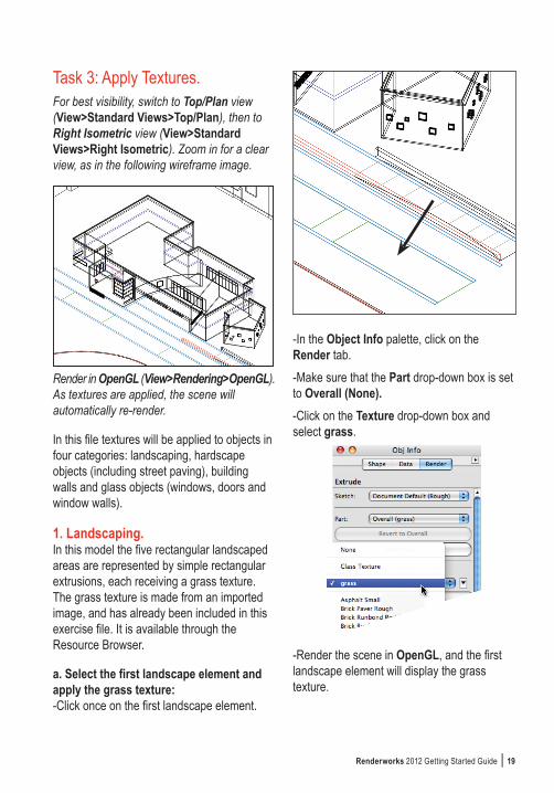
Task 3: Apply Textures.For best visibility, switch to Top/Plan view (View>Standard Views>Top/Plan), then to Right Isometric view (View>Standard Views>Right Isometric). Zoom in for a clear view, as in the following wireframe image.
Render in OpenGL (View>Rendering>OpenGL). As textures are applied, the scene will automatically re-render.
In this file textures will be applied to objects in four categories: landscaping, hardscape objects (including street paving), building walls and glass objects (windows, doors and window walls).
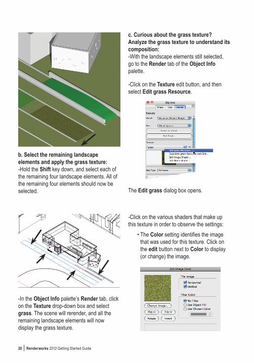
1. Landscaping. In this model the five rectangular landscaped areas are represented by simple rectangular extrusions, each receiving a grass texture. The grass texture is made from an imported image, and has already been included in this exercise file. It is available through the Resource Browser.
a. Select the first landscape element and apply the grass texture:-Click once on the first landscape element.
-In the Object Info palette, click on the Render tab.-Make sure that the Part drop-down box is set to Overall (None).-Click on the Texture drop-down box and select grass.
-Render the scene in OpenGL, and the first landscape element will display the grass texture.
20 | Renderworks 2012 Getting Started Guide
b. Select the remaining landscape elements and apply the grass texture:-Hold the Shift key down, and select each of the remaining four landscape elements. All of the remaining four elements should now be selected.
-In the Object Info palette’s Render tab, click on the Texture drop-down box and select grass. The scene will rerender, and all the remaining landscape elements will now display the grass texture.
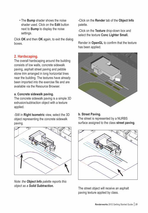
c. Curious about the grass texture? Analyze the grass texture to understand its composition:-With the landscape elements still selected, go to the Render tab of the Object Info palette.
-Click on the Texture edit button, and then select Edit grass Resource.
The Edit grass dialog box opens.
-Click on the various shaders that make up this texture in order to observe the settings:
• The Color setting identifies the image that was used for this texture. Click on the edit button next to Color to display (or change) the image.
Renderworks 2012 Getting Started Guide | 21
• The Bump shader shows the noise shader used. Click on the Edit button next to Bump to display the noise settings.
Click OK and then OK again, to exit the dialog boxes.
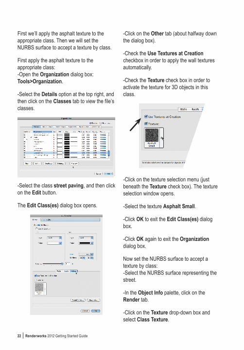
2. Hardscaping.The overall hardscaping around the building consists of low walls, concrete sidewalk paving, asphalt street paving and pebble stone trim arranged in long horizontal lines near the building. The textures have already been imported into the exercise file and are available via the Resource Browser.
a. Concrete sidewalk paving.The concrete sidewalk paving is a simple 3D extrusion/subtraction object with a texture applied.
-Still in Right Isometric view, select the 3D object representing the concrete sidewalk paving.
Note: the Object Info palette reports this object as a Solid Subtraction.
-Click on the Render tab of the Object Info palette.-Click on the Texture drop-down box and select the texture Conc Lighter Small.
Render in OpenGL to confirm that the texture has been applied.
b. Street Paving.The street is represented by a NURBS surface assigned to the class street paving.
The street object will receive an asphalt paving texture applied by class.
22 | Renderworks 2012 Getting Started Guide
First we’ll apply the asphalt texture to the appropriate class. Then we will set the NURBS surface to accept a texture by class.
First apply the asphalt texture to the appropriate class:-Open the Organization dialog box: Tools>Organization.
-Select the Details option at the top right, and then click on the Classes tab to view the file’s classes.
-Select the class street paving, and then click on the Edit button.
The Edit Class(es) dialog box opens.
-Click on the Other tab (about halfway down the dialog box).
-Check the Use Textures at Creation checkbox in order to apply the wall textures automatically.
-Check the Texture check box in order to activate the texture for 3D objects in this class.
-Click on the texture selection menu (just beneath the Texture check box). The texture selection window opens.
-Select the texture Asphalt Small.
-Click OK to exit the Edit Class(es) dialog box.
-Click OK again to exit the Organization dialog box.
Now set the NURBS surface to accept a texture by class:-Select the NURBS surface representing the street.
-In the Object Info palette, click on the Render tab.
-Click on the Texture drop-down box and select Class Texture.

Renderworks 2012 Getting Started Guide | 23
Render in OpenGL to confirm that the texture has been applied.
c. River Stone Trim.
The hardscaping is punctuated by a series of linear trim objects, running parallel to the building’s front (and along one curved wall). In the model these objects are actually simple extrusions. In wireframe view they can be
identified by their light blue color. These linear trim objects will receive the texture river stone, applied directly to each object via the Object Info palette.
Switch to Right Isometric view for easy visibility.
Select the first object and apply the appropriate texture:-Select the linear trim object located furthest from the building.
-In the Object Info palette, click on the Render tab.
-Make sure the Part drop-down box is set to Overall (none).
-Click on the Texture drop-down box and select river stone.
Render in OpenGL to confirm that the texture has been applied properly.

24 | Renderworks 2012 Getting Started Guide
Now select the remaining objects and apply the texture:-Click on the next trim object, and then, pressing and holding the Shift key, click on the remaining objects. There should now be three objects selected.
-In the Object Info palette, click on the Render tab if necessary.
-Make sure the Part drop-down box is set to Overall (none).
-Click on the Texture drop-down box and select river stone.
Render in OpenGL to confirm that the texture has been applied properly to all the remaining objects.
With the three objects selected, the Render tab of the Object Info palette should match the following:
d. Low Walls.The two low walls, running parallel to the building’s front, receive the same texture as the concrete sidewalk paving: Conc Lighter Small.-Click on the first low wall, and then, pressing and holding the Shift key, select the second wall also. Both walls should now be selected.
-In the Object Info palette, click on the Render tab if necessary.
-Make sure the Part drop-down box is set to Overall (none).

Renderworks 2012 Getting Started Guide | 25
-Click on the Texture drop-down box and select Conc Lighter Small.
Now render in OpenGL to confirm that the texture has been applied properly to both walls. This completes the hardscaping adjustments.
3. Building WallsSome of the building’s walls receive a texture representing travertine stone panels. First we will create the texture from an imported image, and then we will apply the texture by class. These are the steps:
a. Create the travertine stone texture.b. Select and then adjust the walls to
receive textures by class.c. Apply the texture to the desired class.d. Fine-tune the texture’s appearance.
The exterior building walls have all been placed in the class main building walls-textured and will receive the texture simultaneously.
a. Create the travertine stone texture:-In the Resource Browser, click on the Resource menu button and select New Resource in building-new.
-Drag the cursor to Renderworks Texture and select it.
The Edit Texture dialog opens.
-In the Name box, type a name for this texture: travertine.
Next, import an image to be used as a source for this texture:-In the Shaders area, click on the Color drop-down box and select Image.
The Choose Image dialog box opens. Select Import an Image File, and click OK.

26 | Renderworks 2012 Getting Started Guide
The Import QuickTime Image Document dialog box opens.
-Click on the drop-down box at the top of the dialog box, and navigate to the folder containing this exercise’s resources: graphics support files.
-Select that folder and click Open.
-Select the image: travertine.png and click Open.
The Edit Image Color dialog box opens, displaying a thumbnail picture of the image we’re selecting. Make sure that all the settings are as shown in the screenshot below.
-Click OK.
We’re back in the Edit Texture dialog box.
Now adjust the size of the texture: -In the Size area at the bottom of the dialog box, click on the Set By Image button. The Set Image Size window opens.
-Grab the little round handle at the upper left side of the window and drag it over to the right edge. The dimension we will enter in the next step will match the size of this handled widget.
-In the Feature Size box enter the desired dimension: 11’0” [3350mm].
-Click OK to exit the Set Image Size window, and then click OK again to exit the Edit Texture dialog box.The new texture is now complete. Look in the Textures pane of the Object Info palette and see the new texture. Next, we will apply the texture to all the walls in the main building walls-textured class. Once these walls have been set to receive their textures by class, all that remains is to assign an actual texture to that class, and the walls will then automatically display that texture.

Renderworks 2012 Getting Started Guide | 27
b. Adjust the walls to receive textures by class:Find the correct walls to receive this texture. The exercise file includes a pre-made script that will instantly pick out those walls. The script is located in the script palette shortcuts.Note: Before proceeding, make sure nothing is selected.
-Open the script palette shortcuts: Window>building-new.vwx/Script Palettes>shortcuts.
-double-click on the script select main building walls-textured.
The walls are now selected and highlighted. The Object Info palette should report that 8 walls are selected.
The walls must now be set to receive textures by class in order to display that class texture:-Click on the Render tab of the Object Info palette.
-Make sure the Toggle Multiple Selection Mode button is set to multiple selections (it will display three dots).
-Set the Part drop-down box to Right (from Overall).
-Click on the Texture drop-down box and select: Class Texture. The Object Info palette will look like the following image.

28 | Renderworks 2012 Getting Started Guide
c. Apply the texture to the desired class:-Open the Organization dialog box.
-Select the Details button (top-right side), and then click on the Classes tab to view the file’s classes.
-Select the class main building walls-textured, and then click on the Edit button. The Edit Class(es) dialog box opens.
-Click on the Walls tab (about halfway down the dialog box).
-Check the Use Textures at Creation checkbox in order to apply the wall textures automatically.
-Click on the Right check box in order to activate the texture for those wall parts.
-Click on the Right texture selection tool.
The texture selection window opens.-Select the texture: travertine.-Click OK to exit the Edit Class(es) dialog box.
-Click OK again to exit the Organization dialog box.
For easier viewing, click on the Saved Views drop-down box and select the View 2. Now click on the Fit To Page Area button. Re-render the scene in Fast Renderworks: View>Rendering>Fast Renderworks.
d. Fine-tune texture appearance.The exterior walls selected earlier will show the stone texture applied. They look, however, a bit flat. We can improve their three-dimensional appearance by adding a three-dimensional quality to the image of the stone (a bit of shade and shadow). We do this by adding a Bump shader to the stone wall texture:-In the Resource Browser, find and select the travertine texture (under Textures).
-Click on the Resource Browser’s edit button (or just right-click) and select: Edit...
The Edit Texture dialog box opens.

Renderworks 2012 Getting Started Guide | 29
-In the Shaders area, click on the Bump drop-down box and select: Image. This means the bump shader is using an image as its source.
The Choose Image dialog box appears.-Click on the Reuse an Image From Another Resource button.
-In the drop-down box, select: This Texture’s Color. This means that we will use the image already selected for the texture as the source for its Bump shader (there are other choices available as well, but we’ll stick to this image as the source here). Click OK.
The Edit Image Bump dialog box appears.
-In the Bump Strength (%) data field type: 2000.
-Click OK to exit the Edit Image Bump dialog box.
-Click OK to exit the Edit Texture dialog box.
Re-render the scene in Fast Renderworks: View>Rendering>Fast Renderworks. The stone texture should have a more three-dimensional appearance now.
How do the walls look? Are the textures on adjacent walls aligned? With the eight exterior walls still selected, make sure the settings in the Object Info palette match those in the following image.

30 | Renderworks 2012 Getting Started Guide
4. GlassThe glass texture used in the building’s windows, doors and storefronts is made entirely within Vectorworks and applied by class. In this exercise file the windows, doors and storefronts have already been set to receive the texture by class. All that remains is to make the glass texture itself, and then assign it to the appropriate class.
a. Create glass texture:-In the Resource Browser, click on the Resource menu button, and then select New Resources in building-new, then Renderworks Texture.
The Edit Texture dialog box opens.
-In the Name box, type this texture’s new name: glass.
This glass texture uses three of the four available shader types used to assemble textures: Color, Reflectivity and Transparency.
Color.-In the Shaders area, click on the Color drop-down box and select Color.
- Click on the Edit button next to Color.
The Edit Color Shader dialog box opens.
-In the Color drop-down selection box, select the color shown below, and click OK.

Renderworks 2012 Getting Started Guide | 31
Note: A very dark-gray color, nearly black, provides a very clear, clean appearance to the glass while adding just a touch of milky opacity.
Reflectivity.-Back in the Shaders area, click on the Reflectivity drop-down box and select Mirror.
-Click on the Edit button next to Reflectivity.
The Edit Mirror Shader dialog box opens.
-Click on the Color drop-down box and select the color white.
-Click in the Reflection data field and enter 80. Leave Blurriness at 0.
-Click OK.
Note: Consider experimenting with the Blurriness setting. An increased setting may provide a significantly more realistic appearance by introducing a bit of blur–but at the cost of greatly-increased rendering times.
Transparency.-Still in the Shaders area, click on the Transparency drop-down box and select Glass.
-Click on the Transparency Edit button.
The Edit Glass Shader dialog box opens.
-Modify the settings to match the following image:

32 | Renderworks 2012 Getting Started Guide
-Make sure the Color setting (in the Edit Glass Shader dialog box) matches the following:
-Click OK.
Back in the Edit Texture dialog box, simply leave all the other settings untouched, and click OK.
b. Assign the Glass texture to the appropriate class: Once the texture has been assigned to the correct class, all the objects in that class will display the texture. The process is similar to the steps taken earlier, when we assigned the travertine wall texture to the appropriate wall class.
-Open the Organization dialog box.
-Select the Details button, and then click on the Classes tab to view the file’s classes.
-Select the class Glazing-Clear, and then click on the Edit button.
The Edit Class(es) dialog box opens.
-Click on the Other tab (about halfway down the dialog box).
-Check the Use Textures at Creation checkbox in order to apply the wall textures automatically.
-Check the Texture check box in order to activate the texture for 3D objects in this class.-Click on the texture selection menu.
The texture selection window opens.
-Select the texture Glass.
-Click OK to exit the Edit Class(es) dialog box.
-Click OK again to exit the Organization dialog box.

Renderworks 2012 Getting Started Guide | 33
Task 4: Add Sky. In this file the graphic image of the sky is a HDRI background supplied with Renderworks and applied as a layer background: HDRI Sky Day Mostly Sunny.
Note: HDRI backgrounds can also be used as lighting sources–they are actually dual-purpose backgrounds. But for this exercise file, the HDRI Sky Day Mostly Sunny layer background will be used only for its image of the sky (a different layer background is used here as a light source, as described in Task 1: Lighting).
-Open the Organization dialog box.-Select the layer site with buildings and click Edit.The Edit Design Layers dialog box opens.-Click on the Renderworks Background drop-down box and select HDRI Sky Day Mostly Sunny.-Click OK, and then back in the Organization dialog box, click OK again.
To see the new sky, click on the Saved Views drop-down box and select the View 1. Now click on the Fit To Page Area button. Re-render the scene in Fast Renderworks: View>Rendering>Fast Renderworks.
Task 5: Add Entourage. This scene uses three types of entourage: one car symbol, several image props of people, and several of trees.
1. Create and place image props.An image prop is, in essence, a three-dimensional flat object onto which an image has been mapped, similar to a billboard. The image prop can be optionally set to automatically rotate toward the camera in order to enhance its appearance and three-dimensionality. With this setting, it is not necessary to orient each image prop in a particular direction (unless desired). One need only place specific image props in the desired locations, and they will automatically point toward the camera in any 3-D view. Additional automated features are optionally available as well, such as the selection of certain colors for transparency, suitable for transparent backgrounds.

34 | Renderworks 2012 Getting Started Guide
This exercise file requires several image props to be installed at various locations, representing trees and people.
a. Make an image prop from a tree image and place it in the scene. Later we will add a number of pre-made image props in various locations.
-Go to the command Model>Create Image Prop...
The Choose Prop Image dialog box will open, prompting us to select an image to be used in the image prop.
-Click on: Import an Image File, and then click OK.
The Import QuickTime Image Document dialog opens.
-Navigate to the folder containing this exercise and, once inside, to the folder graphics support files. The image file to be used for this image prop is located in this folder.
-Select the image tree five image.png and click on the Open button.
The Image Prop Options dialog box opens.
-In the Name data field, type a new name for this image prop: tree five.
-Under Dimensions, change Height to 12’-0” [3660mm], and make sure that the Lock Aspect Ratio checkbox is selected.
Now we’ll make the background color of the tree image transparent, so that only the image of the tree itself will be seen.
-Under Mask Options, select Use Mask, and then click on the Create Mask button.
The Choose Prop Mask Image dialog box opens. To create the transparency mask (required in order to make a portion of the image transparent) we will reuse the image we have already selected:-Click on Reuse an Image from Another Resource.
-Leave the drop-down box at This Prop’s

Renderworks 2012 Getting Started Guide | 35
Color (if that is not the default selection, click on the drop-down box and select This Prop’s Color).
-Click OK.
The Create Mask dialog box opens.
-Select Transparent Color, and click OK.
The Create Transparent Color Mask dialog box opens. We will now select the color to be used as a transparent color mask (anything in that color will be transparent in the image prop). Note that the original image has been prepared with a uniform background of a single color. When making an image prop, it is simpler to pick out a single color and make it transparent.-In the left window, click on the black background color.
-Move the Color Matching Tolerance slider one notch to the right.
-Move the Mask Contrast slider one notch to the right.
-Click OK.
We’re back in the Image Prop Options dialog box.
-Deselect Constant Reflectivity. This setting increases (or maintains) the brightness of the image prop, even when it is in the shade. Not required for our example.-Make sure the Create Symbol checkbox is selected. This will make the image prop into a symbol that can be placed repeatedly throughout the scene.-Make sure the remaining options are as shown below.
36 | Renderworks 2012 Getting Started Guide
-Click OK.
The completed image prop has now been made into a symbol (which can be seen in the Resource Browser). A copy of it has been placed in the scene–at the origin point, where it remains selected and highlighted.
b. Place copies of the new image prop at the desired locations:-First switch to a Top/Plan view and turn on the Entourage Locations layer (View>Layer Options>Show/Snap Others). This layer is a pre-made map showing the desired spots for image props and symbols, including the just-completed image prop.
-In the Organization dialog box, make the Entourage Locations layer visible and click OK.
-Zoom as necessary to include the right half of the building.
-Make sure layer visibility is set to Gray/Snap Others (View>Layer Options>Gray/Snap Others).
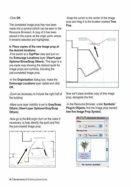
-Now go to the 0-0 origin (turn on the rulers if necessary, to help identify the spot) and find the just-created image prop.
-Snap the cursor to the center of the image prop and drag it to the location marked Tree Five.
Now we’ll place another copy of this image prop, alongside the first.
-In the Resource Browser, under Symbols/Plug-In Objects, find the image prop named: tree five Image Prop Symbol.

Renderworks 2012 Getting Started Guide | 37
-Click/hold on the thumbnail image, and drag/drop the image prop symbol from the Resource Browser onto the drawing, at the second location marked Tree Five, right alongside the first.Now check to see that the image prop was placed properly.-Switch to right isometric view: View>Standard Views> Right Isometric.-Render in Fast Renderworks. Note that the trees do not appear flat, but have rotated to face the camera.
-Switch back to Top/Plan view. Make sure the Entourage Locations layer is visible. Set rendering to Wireframe.
2. Place premade image props.A variety of premade image prop symbols are available in a library file supplied with this exercise. These symbols can be accessed and imported directly within the Resource Browser.
-In the Resource Browser, click on the Files menu button and select Browse a Document.
The Select a Vectorworks Document dialog box opens.-Navigate to the folder containing this exercise, and select the library file building-resources. Click Open.The Resource Browser will now display that file’s resources, including the image prop symbols that have been previously created for this exercise. Find these image prop symbols under Symbols/Plug-In Objects. Drag/drop these symbols directly from the Resource Browser onto the drawing, at the spots marked in gray.

38 | Renderworks 2012 Getting Started Guide
-Select the first image prop symbol, named father and son.-Click/hold on the thumbnail image, and drag the image prop symbol from the Resource Browser onto the drawing, at the location marked Father and Son.
Note that we have imported a symbol from another drawing file, even though that other file is not currently open. The Resource Browser provides access to resources that are located both in the active file, and in other, non-active files as well.
-Now select each of the remaining image prop symbols, and move them one-by-one onto the drawing at the locations marked. The location names match those of the image prop symbols.
3. Place 3D symbols.The Resource Browser should still be displaying the resources in the library file building-resources.
-In the Resource Browser, under Symbols/Plug-In Objects, find the pre-made automobile symbol Auto.
-Click/hold on the symbol’s thumbnail image, and drag the symbol from the Resource Browser onto the drawing, at the location marked AUTO, just in front of Camera 2.
To finish up, switch to view 1 (click on the Saved Views drop-down box and select view 1). Make the underlying Entourage Locations layer invisible (by controlling layer visiibility: View>Layer Options) and render in Fast Renderworks (View>Rendering>Fast Renderworks).
This concludes the file-preparation portion of the exercise.
The final task involves rendering the file and exporting an image.

Renderworks 2012 Getting Started Guide | 39
Task 6: Render and Export an Image.
1. Render the scene.a. Basic Renderworks Methods.We have already used and reviewed a few basic methods for rendering in Renderworks. Fast Renderworks and Final Quality Renderworks represent two points on the rendering quality spectrum. The Fast Renderworks setting makes for a speedy rendering, albeit at the expense of image quality. Final Quality Renderworks is a high-quality rendering mode that provides smooth accuracy and precise representation of lighting–but at the expense of rendering time.
To put it simply:• Fast Renderworks = Higher speed/
lower quality.• Final Quality Renderworks = Higher
quality/lower speed.These two settings will be satisfactory in the majority of cases.
b. Finer Adjustments using Custom Renderworks.To adjust the Renderworks settings more finely, access the individual components of these settings via the Custom Renderworks Options dialog box:View>Rendering>Custom Renderworks Options.
The dialog box provides access to 13 different categories of quality and visibility settings. Once specific settings have been selected, use Custom Renderworks as the rendering option:View>Rendering>Custom Renderworks.
c. Example of a Custom Renderworks setting: For a quick mid-level Custom Renderworks setting–better than Fast Renderworks and faster than Final Quality Renderworks–arrange the Custom Renderworks Options as shown below:

40 | Renderworks 2012 Getting Started Guide
This example is just a starting point. Experiment with the different settings to find a suitable speed-vs.-quality compromise setting.Note the five options at the very top: deselecting several of them (such as Textures or Anti-Aliasing) may significantly increase rendering speed during interim development of renderings.
Once we have arranged the settings as desired, render in Custom Renderworks: View>Rendering>Custom Renderworks.
d. Save new Custom Renderworks settings by using the Saved Views command.After rendering with Custom Renderworks, use the Saved Views command to save the new Custom Renderworks settings along with the view.-View>Save View.
The Save View dialog box opens.
-In the View Name box, enter a desired name for the view. Consider a name that provides information about the settings, such as All Medium Settings, or No Textures.
-Select the Save Render Settings checkbox in order to preserve the Custom Renderworks settings just developed.
-Click OK.
Whenever we call up a saved view, the Custom Renderworks Options developed for that view will be implemented in the rendering. In this way it is possible to save a variety of Custom Renderworks Options. (Custom Renderworks Options can also be saved as Renderworks styles. See page 41).
Note: Custom Renderworks Options settings are also saved with viewports when viewports are rendered. More on that below.
A note about several Custom Renderworks Options:
• Blurriness refers to a setting used when creating textures containing Reflectivity and Transparency shaders.
Blurriness will make those textures appear, as the name implies, blurry to a greater or lesser extent. Clicking the Blurriness checkbox in the Custom Renderworks Options can greatly increase rendering times, but can also increase the realism of a rendering.

Renderworks 2012 Getting Started Guide | 41
For work-in-progress test renderings, deselect the Blurriness setting altogether, and just choose it at the very end, when the final rendering is desired.
• Image Exposure (%) controls the brightness of a rendering. Change the number in the Image Exposure box to fine tune a rendering’s brightness. The default brightness is 100%.
As a reminder, these settings only apply when rendering with Custom Renderworks, and do not affect the appearance of images prepared with Fast Renderworks or Final Quality Renderworks.
e. Use Renderworks Styles to Save TimeFine-tuning Custom Renderworks settings can be time consuming. To speed up the effort, Renderworks provides a series of pre-made settings called Renderworks Styles, available via the Renderworks Style menu (View>Renderworks Style). Selecting a style automatically triggers a new rendering with the style’s settings.
Render using a Renderworks style:-First click on the Saved Views drop-down box, and select View 1. Remember that we already have the lights in place, and active.
-Now render using a Renderworks style: View>Renderworks Style>Realistic Exterior Fast. The scene will render with the new settings.
To see the style’s settings, go to View>Lighting>Set Lighting Options. The Edit Renderworks Style dialog box opens, displaying and providing access to the different parameters used by the style. You can modify any of these options, and subsequent use of the style in this file will reflect the changed parameters.

42 | Renderworks 2012 Getting Started Guide
After altering a style’s settings to a combination you find suitable, save that altered style as a new one by renaming it in the Resource Browser (right-click on the style and select Rename).
To re-create the style’s original settings (before they were modified and the style renamed), simply re-render with the original chosen style. Renderworks will then create the style again, with the original settings.
If you have laboriously created a set of Custom Renderworks settings that you would like to save as a Renderworks style, do the following:
-Render the scene in Custom Renderworks.
-In the Resource Browser, click on the Resources menu button, choose New Resource in..., and then select Renderworks Style.
- The Edit Renderworks Style dialog box will open–with all the Custom Renderworks settings already in place. Give the new style a name, then click OK.
2. Render a viewport.Make a viewport of a saved view, and then render the viewport. Among other advantages, a viewport will save Custom Renderworks settings and make it easy to compare different settings between viewports.
Keep this in mind: each rendered viewport will need its own lighting and rendering quality settings.These are set via the Object Info palette. To compare the results of settings, duplicate the viewports, set them side by side, and then alter the lighting and rendering quality settings for each viewport prior to updating.a. Go to a saved view.-Click on the Saved Views drop-down box, and select View 1.b. Make a viewport.-View>Create Viewport. The Create Viewport dialog box opens. -Leave all the settings in place, and click OK.
Renderworks 2012 Getting Started Guide | 43
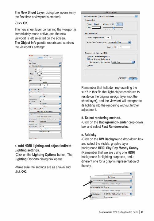
The New Sheet Layer dialog box opens (only the first time a viewport is created).-Click OK.The new sheet layer containing the viewport is immediately made active, and the new viewport is left selected on the screen. The Object Info palette reports and controls the viewport’s settings:
c. Add HDRI lighting and adjust Indirect Lighting settings.-Click on the Lighting Options button. The Lighting Options dialog box opens.
-Make sure the settings are as shown and click OK:
Remember that heliodon representing the sun? In this file that light object continues to reside on the original design layer (not the sheet layer), and the viewport will incorporate its lighting into the rendering without further adjustment.
d. Select rendering method.-Click on the Background Render drop-down box and select Fast Renderworks.
e. Add sky.-Click on the RW Background drop-down box and select the visible, graphic layer background HDRI Sky Day Mostly Sunny. (Remember that we are using one HDRI background for lighting purposes, and a different one for a graphic representation of the sky.)
44 | Renderworks 2012 Getting Started Guide
Why choose a Background Render prior to selecting a sky? Not all rendering methods utilize Renderworks backgrounds, and the RW Background drop-down box will remain grayed-out until a compatible rendering method is chosen.
f. Render by updating the viewport.-In the Object Info palette, click on the Update button. The viewport will render.
The viewport resides on a sheet layer which has a default resolution of 72 dpi (Dots Per Inch). This resolution corresponds to that of many computer monitors, but it is often too coarse for printing, and may yield blurry results on paper. For better printed results increase the sheet layer’s resolution. For print purposes, 300 dpi is often a good setting:
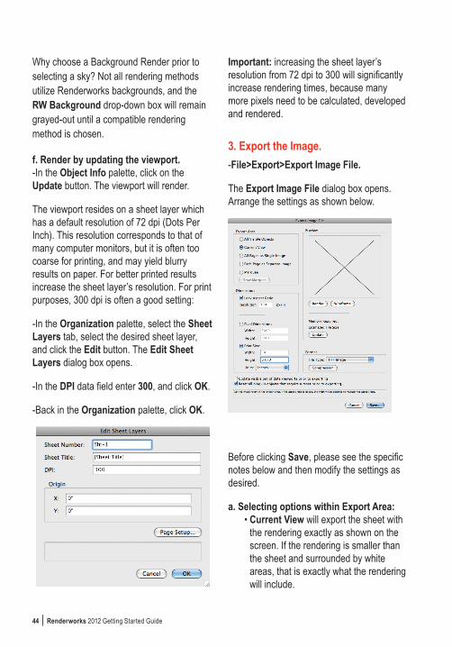
-In the Organization palette, select the Sheet Layers tab, select the desired sheet layer, and click the Edit button. The Edit Sheet Layers dialog box opens.
-In the DPI data field enter 300, and click OK.
-Back in the Organization palette, click OK.
Important: increasing the sheet layer’s resolution from 72 dpi to 300 will significantly increase rendering times, because many more pixels need to be calculated, developed and rendered.
3. Export the Image.-File>Export>Export Image File.
The Export Image File dialog box opens. Arrange the settings as shown below.
Before clicking Save, please see the specific notes below and then modify the settings as desired.
a. Selecting options within Export Area:• Current View will export the sheet with
the rendering exactly as shown on the screen. If the rendering is smaller than the sheet and surrounded by white areas, that is exactly what the rendering will include.
Renderworks 2012 Getting Started Guide | 45
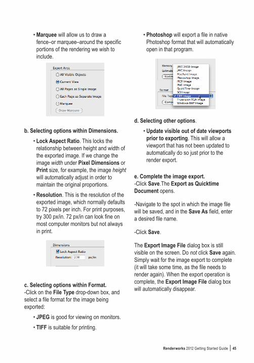
• Marquee will allow us to draw a fence–or marquee–around the specific portions of the rendering we wish to include.
b. Selecting options within Dimensions.• Lock Aspect Ratio. This locks the
relationship between height and width of the exported image. If we change the image width under Pixel Dimensions or Print size, for example, the image height will automatically adjust in order to maintain the original proportions.
• Resolution. This is the resolution of the exported image, which normally defaults to 72 pixels per inch. For print purposes, try 300 px/in. 72 px/in can look fine on most computer monitors but not always in print.
c. Selecting options within Format.-Click on the File Type drop-down box, and select a file format for the image being exported:
• JPEG is good for viewing on monitors.• TIFF is suitable for printing.
• Photoshop will export a file in native Photoshop format that will automatically open in that program.
d. Selecting other options.• Update visible out of date viewports
prior to exporting. This will allow a viewport that has not been updated to automatically do so just prior to the render export.
e. Complete the image export.-Click Save.The Export as Quicktime Document opens.
-Navigate to the spot in which the image file will be saved, and in the Save As field, enter a desired file name.
-Click Save.
The Export Image File dialog box is still visible on the screen. Do not click Save again. Simply wait for the image export to complete (it will take some time, as the file needs to render again). When the export operation is complete, the Export Image File dialog box will automatically disappear.

46 | Renderworks 2012 Getting Started Guide

Renderworks 2012 Getting Started Guide | 47
Section 2:Day-Time Interior View
Section 2 of this guide will focus on rendering an office interior, daylit through a window wall. The exercise file has already been partially set up with textures and cameras.
What will this exercise cover? We will install and adjust lighting and then add a layer background, essentially a sky graphic, to be seen through the window wall on the left. We will apply textures to the rear-most wall behind the stairs, the partial-height mesh partition just in front of the rear steps and the wood paneling on the right, beneath the upper mezzanine. Finally, we will render in Custom Renderworks. The exercise will focus on the following tasks:
1. Placing a sun-light and a HDRI background, adding light from the sky.
2. Setting the appropriate light quality settings.
3. Adding a layer background representing the sky (seen through the window wall).
4. Creating and applying three textures to interior surfaces.
5. Rendering using Custom Renderworks.

48 | Renderworks 2012 Getting Started Guide
Open the file: Interior-day.vwx. Take a quick first look:-Go to the Saved Views drop-down box and select view 1. The view will be in wireframe.
-Make a quick first rendering using Fast Renderworks: View>Rendering>Fast Renderworks (seen above).
Task 1: Place a Heliodon Representing the Sun. In the Tool Sets palette, click on the Visualization tool set, and then double-click on the Heliodon tool.
A Heliodon will be placed in the scene, and the Create Object dialog box will open.
-Click on the Settings button. The Settings dialog box opens.

Renderworks 2012 Getting Started Guide | 49
-Under Location, click on the Region drop-down box and select USA. Now click on the City drop-down box and select Albuquerque. Click OK.
-Back in the Create Object dialog box, enter the following information:
Time: 3:30 PMDay: 26Month: June
Leave everything else as-is, and click OK.
Task 2: Lighting: Add Light from the Sky.a. Use a HDRI background as a light source (light from the sky) for the scene: -View>Lighting>Set Lighting Options. The Lighting Options dialog box opens.
-Under Environment Lighting (HDRI), click on From Selected Background.
b. Now select the desired HDRI background: -Click on the Renderworks Background drop-down box and select: HDRI Day.
-Click OK.
-Render in Fast Renderworks to see the results.

50 | Renderworks 2012 Getting Started Guide
Task 3: Lighting: set Lighting Options.Access the Lighting Options dialog box:-View>Lighting>Set Lighting Options.
The Lighting Options dialog box opens. -Click on the Indirect Lighting drop-down box and select Interior, 4 Bounces.
A good quality indirect lighting setting for interiors uses 2 bounces. Using fewer bounces can often yield unsatisfactory results. 4 bounces is the best setting for interiors but at the occasional cost of lengthy rendering times (depending on the file).
-Make sure the remaining settings are as shown below.
-Click OK to finish.
Task 4: Add a Graphic Sky Background.Use a High Dynamic Range Image background for its graphic sky image, to be seen through the window wall to the left of the image:-Open the Organization dialog box.
-Select the layer Design layer-1 and click Edit.
-The Edit Design Layers dialog box opens. Click on the Renderworks Background drop-down box and select HDRI Sky Day Mostly Sunny.

Renderworks 2012 Getting Started Guide | 51
-Click OK, and then back in the Organization dialog box, click OK again.
Task 5: Create and Apply Textures.Create three textures and apply them to interior surfaces:
1. Rear wall The first texture is applied to the rear wall and represents textured plaster. This texture will take on the color of the wall, and recreates the plaster texture through use of the Noise bump shader.
a. Create texture.First, create a new texture:-In the Resource Browser, click on the Resource menu button, and then select New Resources in Interior-day.vwx, then Renderworks Texture.
The Edit Texture dialog box opens.
-In the Name box, type this texture’s new name: Plaster.
This plaster texture uses one of the four available shader types used to assemble textures: Bump, which adds a 3-D appearance to a texture:-In the Shaders area, click on the Bump drop-down box and select Noise.
- Click on the Edit button.
The Edit Noise Shader dialog box opens.
-Click on the Pattern drop down box and select Wavy Turbulence.
-Make sure the remaining settings are as shown below. Note some of the features that are particular to this specific Noise-based texture: Strength is only 15%, Detail is 6, and Cycles: 2.

52 | Renderworks 2012 Getting Started Guide
These last two settings are especially important in this shader. As an experiment, change each of these and observe the thumbnail image at the top of the dialog box to see the changes made.-Click OK. We’re back in the Edit Texture dialog box.Now change the size of the texture:-In the Edit Texture dialog box, click in the Size data field and enter 6’0”. (Why 6’0”? Trial and error–it just looks good. Change it and see if you prefer a different size.)-Click OK.Note: to change the size of a completed texture, right-click (or Control-click) on the texture in the Resource Browser and choose Edit... . This will launch the Edit Texture
dialog box, and the texture’s size can be changed in the Size data field.
b. Apply the new texture to the rear wall.-Switch to Top/Plan view.Select the wall:-Click once on the rear, orange wall.Now go to the Object Info palette to apply the texture.
-In the Object Info palette, click on the Render tab.
-Click on the Mode drop-down box. Select: By Object.

Renderworks 2012 Getting Started Guide | 53
Select the wall part to which the texture is applied:-Click on the Part drop-down box and select Overall.
Now choose the texture:-Click in the Texture drop-down box and select the new texture, Plaster.
Now switch to the saved view and render to see the results:-Click on the Saved Views drop-down box and select view 1.
-Render in Fast Renderworks.
2. Mesh partition.The second texture is applied to the partial-height wall in front of the stairs. This wall is actually a metal-mesh partition.
a. Create Texture.
-In the Resource Browser, click on the Resource menu button, and then select New Resources in Interior-day.vwx. Then select Renderworks Texture.The Edit Texture dialog box opens.-In the Name box type this texture’s new name: Metal Mesh.This mesh texture uses two of the four available shader types used to assemble textures: Color and Transparency.
First we’ll decide on a mesh color to use in this texture:
-In the Shaders area, click on the Color drop-down box and select Color.
- Click on the Edit button.The Edit Color Shader dialog box opens.
-Click on the Color drop-down box and select the color shown below. Then click OK.
Now we’ll apply a patterned transparency to the texture (the pattern representing the mesh material itself):

54 | Renderworks 2012 Getting Started Guide
-Back in the Edit Texture dialog box, click on the Transparency drop-down box and select Tiles.-Click on the Edit button.The Edit Tiles Shader dialog box opens.-Click on the Pattern drop-down box and select Squares.-Make sure the remaining settings match those shown below, and click OK.
-Back in the Edit Texture dialog box, click in the Size data field and enter the desired size for a single tile of this texture: 1’-0”.
-Click OK.
b. Apply the new texture to the wall in front of the stairs.
-Switch to Top/Plan view (View>Standard Views>Top/Plan).
-Select the partial-height wall just in front of the stairs.
Note: In the file the wall is actually made with a simple extrusion.
-In the Object Info palette, click on the Render tab.
Now select the part to which the texture is applied:-Click on the Part drop-down box and select Overall.
Select the texture:-Click in the Texture drop-down box and select the new texture, Metal Mesh.
Switch to the saved view and render to see the results:

Renderworks 2012 Getting Started Guide | 55
-Click on the Saved Views drop-down box and select view 1.-Render in Fast Renderworks (View>Rendering>Fast Renderworks).
3. Wood paneling.The third texture is applied to a 3-D object (a Solid Subtraction) on the right side, representing wood paneling.
a. Create the texture.
-In the Resource Browser, click on the Resource menu button, and then select New Resources in Interior-day.vwx, then Renderworks Texture.
The Edit Texture dialog box opens.
-In the Name box type this texture’s new name: Wood Paneling.
Note: This texture uses two of the four available shader types used to assemble textures: Color and Reflectivity. This texture also uses a graphic image file as the texture source. The next step will select the image file to be used in this texture.
-In the Shaders area, click on the Color drop-down box and select Image. The Choose Image dialog box opens.
In this case we are importing an image file into our Vectorworks file:-Select the first item, Import an Image File. Click OK.
The Import QuickTime Image Document opens. Select the image file to be imported:-Navigate to the folder containing this file (Day-Time Interior View>resources) and select the image file wood paneling.png. Then click Open.
56 | Renderworks 2012 Getting Started Guide
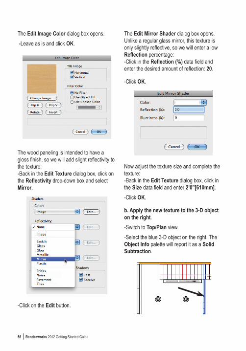
The Edit Image Color dialog box opens. -Leave as is and click OK.
The wood paneling is intended to have a gloss finish, so we will add slight reflectivity to the texture:-Back in the Edit Texture dialog box, click on the Reflectivity drop-down box and select Mirror.
-Click on the Edit button.
The Edit Mirror Shader dialog box opens. Unlike a regular glass mirror, this texture is only slightly reflective, so we will enter a low Reflection percentage:-Click in the Reflection (%) data field and enter the desired amount of reflection: 20.
-Click OK.
Now adjust the texture size and complete the texture:-Back in the Edit Texture dialog box, click in the Size data field and enter 2’0”[610mm].-Click OK.
b. Apply the new texture to the 3-D object on the right.-Switch to Top/Plan view.-Select the blue 3-D object on the right. The Object Info palette will report it as a Solid Subtraction.

Renderworks 2012 Getting Started Guide | 57
-In the Object Info palette, click on the Render tab.
Now select the part to which the texture is applied:-Click on the Part drop-down box and select Overall.
Select the texture:-Click in the Texture drop-down box and select the new texture, Wood Paneling.
Switch to the saved view and render to see the results:-Click on the Saved Views drop-down box and select view 1, and then render in Fast Renderworks.
Task 6: Render using Custom Renderworks.This exercise develops a Custom Renderworks setting as a compromise between Fast Renderworks and Final Quality Renderworks. By setting some controls to Low and others to Medium, deselecting Blurriness and reducing the Max Reflections, we accomplish a compromise: relatively quick rendering speed with acceptable image quality.a. Access the Custom Renderworks settings:-View>Rendering>Custom Renderworks Options.b. Select the appropriate settings as shown below:

58 | Renderworks 2012 Getting Started Guide
c. Render in Custom Renderworks:
View>Rendering>Custom Renderworks.
Enlarged detail:
As described in the previous chapter, try using Renderworks styles as an alternate to the
various Custom Renderworks settings (View>Renderworks Style). Either Realistic Interior Fast or Realistic Interior Final may well provide acceptable settings for this file (note that the latter will require lengthier rendering times). Adjusting the selected style may yield even better results.
Don’t forget–you can also save the Custom Renderworks settings developed for this scene as a Renderworks style by following the earlier description on page 42. Once saved, the style can be used in other files as well, since a Renderworks style is a resource that can be exported or imported via the Resource Browser.

Renderworks 2012 Getting Started Guide | 59
Section 3:Night-Time Interior View The Vectorworks exercise file for this section has already been partially set up with textures, cameras, saved views and a layer background representing an urban night scene (viewed through the window wall).
The scene also has 3-D models of light fixtures in place, but lacks actual Vectorworks lights. This exercise will focus on the following tasks:
1. Placing and adjusting lights.2. Setting the appropriate light quality
settings.3. Rendering using Custom Renderworks.
4. Adjusting Custom Renderworks settings to control the scene’s brightness.
Note that darker scenes (or night views) often require longer rendering times than fully-lit ones.-Open the file: Night-Time Interior View>Interior-night.vwx.
-Switch to Top/Plan view. This will make it easier to modify each light fixture.

60 | Renderworks 2012 Getting Started Guide
The fixtures used in this scene are the following:
A. Ceiling-mounted lights: rectangular fluorescents above the mezzanine to the right.
B. Round, surface-mount industrial fixtures over the two-story portion of the space.
C. Ceiling-suspended pendants: two pendant lights over the reception counter, at center rear.
D. One fluorescent fixture suspended over the conference table at the front.
E. Rear signage at the mesh partition (in front of the stairs): neon lights outlining the logo’s letters.
This exercise will install light objects in each of the 3-D light models depicted in the scene and use them to illuminate the space.
Task 1, Lighting: Place and Adjust Lights.
A. Rectangular fluorescents.The ceiling-mount rectangular fluorescent light fixtures are located above the mezannine to the right. The 3-D model of this luminaire has been saved as a symbol. We will edit the rectangular fluorescent symbol and place an Area light in it to represent the fluorescent light’s lens. Once the symbol is modified, all instances of this light fixture will automatically reflect this change.
-Select one example of this fixture on the drawing, and double-click on it in order to edit the symbol.The Edit Symbol dialog box opens.
-Select 3D Component, and then click Edit.
The file now goes into Symbol Edit mode, and displays the light fixture in Top/Plan view.
-Zoom in on the object for clarity.
Now prepare an Area light:-Using the Rectangle tool, draw a 2-D rectangle on top of the light fixture. Give the rectangle a white fill, and make sure the rectangle fits within the boundaries of the fixture.
BA
C
D
E
draw rectangle

Renderworks 2012 Getting Started Guide | 61
With the rectangle selected, convert it to an Area light:-Modify>Convert>Convert to Area Light.
The Light Preferences-Area Light dialog box opens. Make sure the settings are as shown below:
Particularly important is the light’s strength, 7500 Lumens (in the Get Brightness From: User Input data field).
-Click on the Area Light Specs... button. The Area Light Data dialog box opens.
-Click on the Distance Falloff drop-down box and select Realistic.
-Click on the Quality drop-down box and select From Render Mode.
-Click on the Render Geometry checkbox and make sure it remains selected.
-Click OK.
-Back in the Light Preferences-Area Light dialog box, click OK.
Now adjust the height of the new area light:-Switch to Front view and locate the area light (it will appear as a line).
-Move the Area light down to the location shown below:
-Exit the symbol. This fixture is complete. Before proceeding, switch back to Top/Plan view and zoom out to show the entire drawing.
B. Round, surface-mount fixtures.The ceiling-mount round fixtures are located above the 2-story portion of the space. The 3-D model of this fixture has been saved as a symbol. We will edit the symbol to place a Point light inside it. Once the symbol is modified, all instances of this light fixture will automatically reflect the change.
-Select one example of this fixture on the drawing, and double-click to edit the symbol.The Edit Symbol dialog box opens.
-Select 3D Component, and then click Edit.
The file now goes into Symbol Edit mode and

62 | Renderworks 2012 Getting Started Guide
displays the light fixture in Top/Plan view.
-Zoom in on the object for clarity.
Now place a point light in the fixture:-In the Visualization tool set, click once on the Light tool.
-Up in the mode bar, select the Point Light Mode.
-Click once in the center of the light fixture in order to place the light.
The Light Preferences-Point Light dialog box opens. Make sure all the settings are as shown below.
Note that the Use Emitter checkbox is selected, allowing more precise control over the light’s characteristics. The light’s strength is set to 11,000 Lumens (it is intended to be a metal halide lamp).
-Click on the Point Light Specs... button. The Point Light Data dialog box opens.
-Click on the Distance Falloff drop-down box and select Realistic.
-Click OK.
-Back in the Light Preferences-Point Light dialog box, click OK.
Now adjust the height of the new point light so that it fits properly within the 3-D model of the light bulb, inside the fixture:-Switch to Front view, and locate the Point light.
-Move the Point light into position as shown below:

Renderworks 2012 Getting Started Guide | 63
-Exit the symbol by clicking the Exit Symbol button at the top-right side of the drawing area. This fixture is now complete. Before proceeding, switch back to Top/Plan view (View>Standard Views>Top/Plan) and zoom out to show the entire drawing.
C. Pendant lights at reception counter.Two lights are suspended from the ceiling, hanging low over the reception counter. Each of these is a symbol of a 3-D model of a light. We will edit the symbol to place a point light within it.
-Zoom in to the reception desk area for clarity.
-Select one example of this fixture on the drawing, and double-click on it in order to edit the symbol.The Edit Symbol dialog box opens.
-Select 3D Component, and then click Edit.
The file now goes into Symbol Edit mode, and displays the light fixture in Top/Plan view.
-Zoom in further on the object for additional clarity.
Now place a point light in the fixture:-In the Visualization tool set, click once on the Light tool.
-In the mode bar, select the Point Light Mode.
-Click once in the very center of the light fixture in order to place the light. The Light Preferences-Point Light dialog box opens. Make sure all the settings are as shown below, and that the Brightness slider is at 60%.
-Click on the Point Light Specs... button. The Point Light Data dialog box opens.
-Click on the Distance Falloff drop-down box and select Realistic.
-Click OK.
-Back in the Light Preferences-Point Light dialog box, click OK.

64 | Renderworks 2012 Getting Started Guide
-Switch to Front view and locate the Point light.
-Move the Point light into position in the fixture as shown below:
-Exit the symbol. This fixture is complete. Before proceeding, switch back to Top/Plan view and zoom out to show the entire drawing.
Note: Prior to exiting the symbol, consider clicking on individual portions of the overall light fixture and reviewing them in the Object Info palette. Several components–such as the light bulb and the shade–have textures applied (visible via the Render tab of the Object Info palette), displaying complete or partial transparency and reflection.
D. Fluorescent pendant light over conference table.A long fluorescent light fixture is suspended from the ceiling over the conference table. The 3-D model of the fixture is a symbol. We will edit the symbol in order to insert an Area light representing the light’s lens.
-Select this fixture on the drawing, and
double-click on it to edit the symbol.The Edit Symbol dialog box opens.
-Select 3D Component, and then click Edit.
The file now goes into Symbol Edit mode, and displays the light fixture in Top/Plan view.
-Zoom in on the object for clarity.
Now prepare an Area light:-Using the Rectangle tool, draw a 2-D rectangle on top of the light fixture. Give the rectangle a white fill, and make sure the rectangle fits within the boundaries of the fixture.
With the rectangle selected, convert it to an Area light:-Modify>Convert>Convert to Area Light.
The Light Preferences-Area Light dialog box opens. Make sure the settings are as shown below:
draw rectangle

Renderworks 2012 Getting Started Guide | 65
Note: Particularly important is the light’s strength, 20000 Lumens (in the Get Brightness From: User Input data field).
-Click on the Area Light Specs... button. The Area Light Data dialog box opens.
-Click on the Distance Falloff drop-down box, and select Realistic.
-Click on the Quality drop-down box, and select From Render Mode.
-Click on the Render Geometry checkbox and make sure it remains selected.
-Click OK.
-Back in the Light Preferences-Area Light dialog box, click OK.
Now adjust the height of the new area light:-Switch to Front view and locate the Area light (it will appear as a line).
-Move the Area light to the location shown below:
-Exit the symbol. This fixture is complete. Before proceeding, switch back to Top/Plan view and zoom out to show the entire drawing.
Note: Since the Area light directs light in both directions, its illumination can be seen both on the conference table and through the small slit openings in the top of the light fixture.
E. Rear signage at the mesh partition (in front of the stairs).The mesh partition in front of the rear stairs contains a three-dimensional company logo, outlined in yellow neon. The neon lighting is actually a 3-D solid composed of three path extrudes, with a light-emitting Glow texture applied. Even though the model of this lighting emits light (because of the Glow texture), it is not technically a Vectorworks light object.

66 | Renderworks 2012 Getting Started Guide
The 3-D model of the neon tubing has already been created and placed. This exercise will focus on creating the light-emitting Glow texture and applying it to the 3-D model of the neon tubing.
a. Create the texture.-In the Resource Browser, click on the Resource menu button, then select New Resources in Interior-night.vwx, then Renderworks Texture.
-The Edit Texture dialog box opens. In the Name box, type this texture’s new name: Neon Light.
This texture uses two of the four available shader types used to assemble textures: Color and Reflectivity.First we will set the texture’s color:-In the Shaders area, click on the Color drop-down box and select Color, then click on the Edit button at the side. The Edit Color Shader dialog box opens. -Click on the Color drop-down box and select the color shown below, and then click OK.
Click OK again to exit the Edit Color Shader dialog box. Now we will select the Glow setting, available in the Reflectivity shader. This setting causes the texture to emit light, not unlike a light object:-Back in the Edit Texture dialog box, click on the Reflectivity drop-down box, and select Glow.-Click on the Edit button to the right of Reflectivity. The Edit Glow Shader dialog box opens.-Click in the Brightness (%) data field, and enter 100.-Select Emit Light and then click OK.

Renderworks 2012 Getting Started Guide | 67
-Back in the Edit Texture dialog box, click OK to complete the texture.
b. Apply the new neon light texture to the 3-D model of the neon tubing.-Switch to Top/Plan view and zoom in on the neon light model for clarity.
-Select the 3-D lettering model (outlined in blue), and in the Object Info palette, click on the Render tab.
-Click on the Part drop-down box, and select Overall.
-Click on the Texture drop-down box, and select Neon Light.
The texture is now applied to the 3-D model of the neon tubing. Task 1 is complete.
Task 2: Lighting: Set the Appropriate Light Quality Settings.Access the Lighting Options dialog box:-View>Lighting>Set Lighting Options.
For the fastest, reasonable-quality results (with illumination from lights, not a Heliodon or HDRI), try turning off Indirect Lighting and using Ambient lighting instead, set to about 30%.
For better results, turn off Ambient lighting, and use Indirect Lighting set to 2 bounces. This will increase rendering time by about one-third compared to Indirect lighting.

68 | Renderworks 2012 Getting Started Guide
For superior results, however, and a cleaner, lighter image (more light bounces send more light energy around the scene, increasing its brightness), set Indirect Lighting to 4 bounces. This will increase rendering time by about 40% compared to 2 bounces (your mileage may vary, depending on the file, number of lights, etc.).
-Once you have decided on your preferred lighting options, click OK to finish.
Task 3. Render using Custom Renderworks.This exercise develops a Custom Renderworks setting as an optimal compromise between speed and quality of rendering. Try rendering in Fast Renderworks and Final Quality Renderworks to see the impact of those settings. Then modify Custom Renderworks settings as shown here, as an experiment.
After setting some Custom Renderworks controls to Low and others to Medium, deselecting Blurriness and reducing the Max Reflections, these settings yield relatively quick rendering speed with acceptable image quality. The settings shown here are merely a suggestion. Experiment with different settings to find the combination that best suits your purpose.
Before proceeding, switch to View 1 (click on the Saved Views drop-down box and select View 1).
a. Access the Custom Renderworks settings:-View>Rendering>Custom Renderworks Options.
b. Adjust the settings as shown below:

Renderworks 2012 Getting Started Guide | 69
c. Render in Custom Renderworks:View>Rendering>Custom Renderworks.
Task 4. Adjust Custom Renderworks Settings to Control Brightness.If the scene’s brightness does not match your preference, it is possible to modify the overall brightness of the image by changing the Image Exposure (%) setting in Custom Renderworks.
a. Access the Custom Renderworks settings:-View>Rendering>Custom Renderworks Options.
b. In the Image Exposure (%) data field enter a number greater or smaller than 100 (100 is the default setting, a smaller number makes the scene darker and vice versa).
As mentioned in the previous chapter–you can save the Custom Renderworks settings developed for this scene as a Renderworks style by following the earlier description on page 42. Once saved, the style can be used in other files as well, since a Renderworks style is a resource that can be exported or imported via the Resource Browser.

70 | Renderworks 2012 Getting Started Guide
Notes

Renderworks 2012 Getting Started Guide | 71
About the Author
Daniel Jansenson is an architect in private practice based in Santa Monica, California. A longtime Vectorworks user, he teaches seminars in the use of Vectorworks and Renderworks, presentation graphics and small-office project management. Author of the Renderworks Recipe Book and Remarkable Renderworks, Dan uses Vectorworks daily in his residential and small commercial practice. His focus is on the daily joys of designing homes, and having as much fun as humanly possible both in the design of buildings and in the creation of rendered presentations.
Dan can be reached via his firm’s web site: www.danjansenson.com. His training activities are available through www.vectortasks.com.

72 | Renderworks 2012 Getting Started Guide