2012 British Columbia Plumbing Code Update - · PDF file2012 British Columbia Plumbing Code...
98
2012 British Columbia Plumbing Code Update
Transcript of 2012 British Columbia Plumbing Code Update - · PDF file2012 British Columbia Plumbing Code...

2012
British Columbia
Plumbing Code
Update

2012 British Columbia Plumbing Code
is published as a separate document
and is broken down into Divisions similar to BCBC

Division A
Division A
Part 1 – Compliance
Part 2 – Objectives
Part 3 – Functional Statements
Appendix A (Division A)
A-1.4.1.2.(1) Defined Terms
Division A
Appendix A
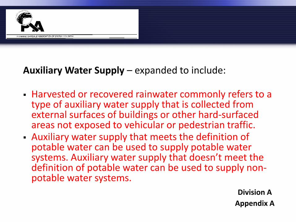
Auxiliary Water Supply – expanded to include: Harvested or recovered rainwater commonly refers to a
type of auxiliary water supply that is collected from external surfaces of buildings or other hard-surfaced areas not exposed to vehicular or pedestrian traffic.
Auxiliary water supply that meets the definition of potable water can be used to supply potable water systems. Auxiliary water supply that doesn’t meet the definition of potable water can be used to supply non-potable water systems.
Division A
Appendix A

Division B
Division B
Part 1 – General
Part 2 – Plumbing Systems
Appendix A (Division B)

1.3.1.2. Applicable Editions
1) Where documents are referenced in this Code, they shall be the editions designated in Table 1.3.1.2.
Referenced Editions of Documents and Standards
have been updated
example NFPA 13D-2007 Division B
Part 1
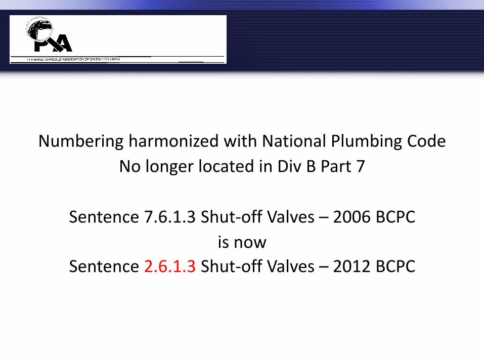
Numbering harmonized with National Plumbing Code
No longer located in Div B Part 7
Sentence 7.6.1.3 Shut-off Valves – 2006 BCPC
is now
Sentence 2.6.1.3 Shut-off Valves – 2012 BCPC
Part 2 Plumbing Systems
Section 2.1 – General
Section 2.2 – Material and Equipment
Section 2.3 – Piping
Section 2.4 – Drainage Systems
Section 2.5 – Venting Systems
Section 2.6 – Potable Water Systems
Section 2.7 – Non-Potable Water Systems
Section 2.8 – Objectives and Functional Statements
Appendix A (Division B)

2.1.2.1. Sanitary Drainage Systems
1) Except as provided in Subsection 2.7.4., every sanitary drainage system shall be connected to a public sanitary sewer, a public combined sewer or a private sewage disposal system.
2.7.4.1. Non-potable Water System Design
Clarifies that non-potable water systems are permitted.
Division B
Part 2
Also applies to
2.1.2.2. – Storm Drainage Systems
2.1.2.3. – Water Distribution Systems
Each of these sentences starts with the wording “Except as provided in Subsection 2.7.4.,”
Division B
Part 2

2.2.5.13. Polyethylene/Aluminum/Polyethylene Composite Pipe and Fittings
2) Except as provided in Sentences (3) and (4), PE/AL/PE pipe and fittings shall not be used in hot water systems.
3) PE/AL/PE pipe with a pressure rating of 690 kPa or
greater at 82°C shall be permitted for hot water systems.
Division B
Part 2

4) PE/AL/PE pipe with a pressure rating of 690 kPa or greater at 82°C shall be used with fittings that conform to CAN/CSA-B137.10, “Crosslinked Polyethylene/Aluminum/Crosslinked Polyethylene (PEX-AL-PEX) Composite Pressure-Pipe Systems,” in hot water systems.
Division B
Part 2
2.2.10.6. Supply and Waste Fittings
1) Supply fittings shall conform to a) ASME A112.18.1/CAN/CSA-B125.1 “Plumbing Supply
fittings” or b) CAN/CSA-B125.3 “Plumbing Fittings.”
2) Waste fittings shall conform to ASME A112.18.2/CAN/CSA-B125.2. “Plumbing Waste
Fittings”.
Division B
Part 2
2.2.10.7. Water Temperature Control (See Appendix A.)
1) Except as provided in Sentence (2), all valves supplying fixed-location shower heads shall be individual pressure-balanced or thermostatic-mixing valves conforming to ASME A112.18.1/CAN/CSA-B125.1, “Plumbing Supply Fittings.”
2) Individual pressure-balanced or thermostatic-mixing valves shall not be required for showers having a single tempered water supply that is controlled by a master thermostatic-mixing valve conforming to CAN/CSA-B125.3, “Plumbing Fittings.”
Division B
Part 2
2.2.10.7. Water Temperature Control (cont.)
3) All mixing valves supplying shower heads shall be of the pressure-balanced, thermostatic, or combination pressure-balanced/thermostatic type capable of
a) maintaining a water outlet temperature that does not exceed 49°C, and
b) limiting thermal shock.
4) The temperature of water discharging into a bathtub shall not exceed 49°C.
Division B
Part 2
A-2.2.10.7. Hot Water Temperature
Hot water delivered at 60°C will severely burn human skin in 1 to 5 seconds. At 49°C, the time for a full thickness scald burn to occur is 10 minutes. Children, the elderly and persons with disabilities are particularly at risk of scald burns. Compliance with Article 2.2.10.7. will reduce the risk of scalding in showers and bathtubs, and reduce the risk of thermal shock from wall-mounted shower heads.
Division B
Appendix

These requirements apply to all occupancies, not just
residential occupancies. The water outlet temperature at other fixtures, such as
lavatories, sinks, laundry trays or bidets, is not addressed by Article 2.2.10.7., but a scald risk may exist at such fixtures nonetheless
Division B
Appendix

2.2.10.14. Vent Pipe Flashing
1) Flashing fabricated on-site for vent pipes shall be fabricated from
b) aluminum sheet not less than 0.48mm thick d) lead sheet not less than 1.73mm thick e) galvanized steel sheet not less than 0.33mm thick
Division B
Part 2

2.4.2.1. Connections to Sanitary Drainage Systems
4) Where a change in direction of more than 45 degrees occurs in a soil-or-waste pipe that serves more than one clothes washer, and in which pressure zones are created by detergent suds, no other soil-or-waste pipe shall be connected to it within a length less than
a) 40 times the size of the soil-or-waste pipe or 2.44 m maximum vertical, whichever is less, before changing direction, and
b) 10 times the size of the nominally horizontal soil-or-waste pipe after changing direction.
(See Appendix A.)
Division B
Part 2

2.4.2.1. Connections to Sanitary Drainage Systems (cont.) 5) Where a vent pipe is connected into the suds pressure
zone referred to in Sentence (4), no other vent pipe shall be connected to that vent pipe within the height of the suds pressure zone. (See A-7.4.2.1.(4) in Appendix A.)
Division B
Part 2
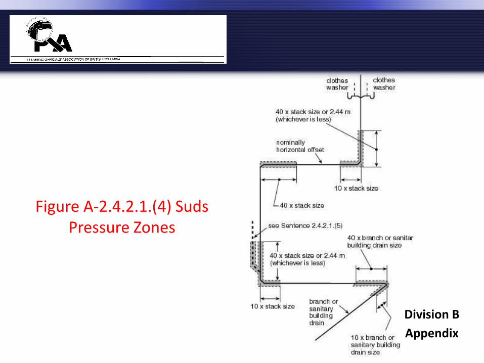
Figure A-2.4.2.1.(4) Suds Pressure Zones
Division B
Appendix

Table 2.4.9.3. Minimum Permitted Size of Fixture Outlet Pipe and
Hydraulic Loads for Fixtures Clothes washer Min/size Hydraulic Load, Fixture Units
(a) domestic n/a 2 with 2-in. trap (b) commercial n/a 2 with 2-in. trap Macerating toilet ¾” 4
system Division B
Part 2
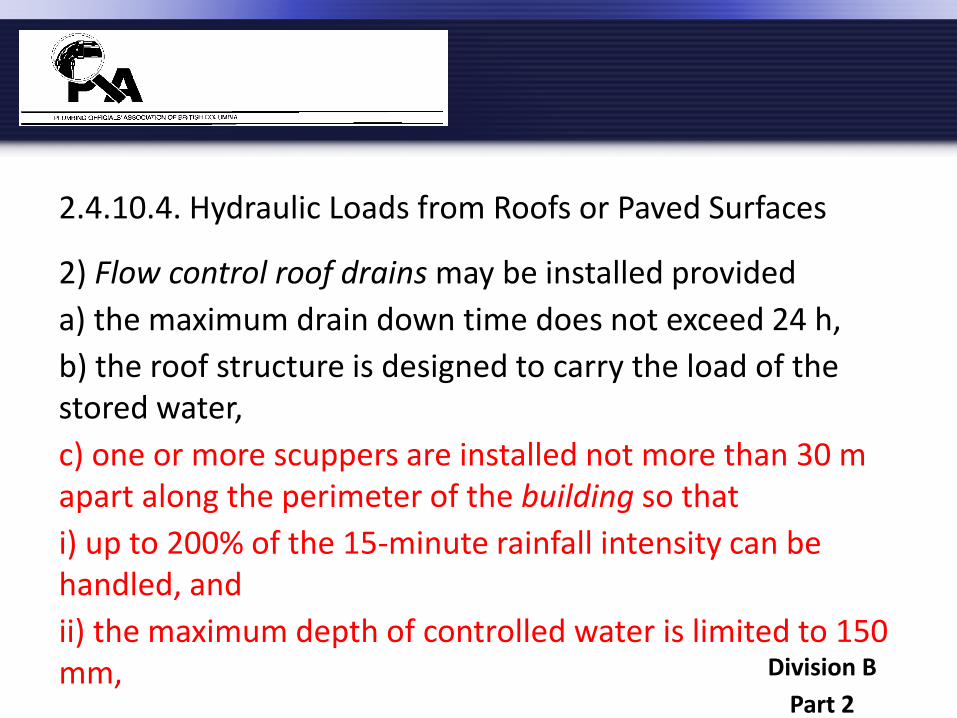
2.4.10.4. Hydraulic Loads from Roofs or Paved Surfaces
2) Flow control roof drains may be installed provided
a) the maximum drain down time does not exceed 24 h,
b) the roof structure is designed to carry the load of the stored water,
c) one or more scuppers are installed not more than 30 m apart along the perimeter of the building so that
i) up to 200% of the 15-minute rainfall intensity can be handled, and
ii) the maximum depth of controlled water is limited to 150 mm, Division B
Part 2
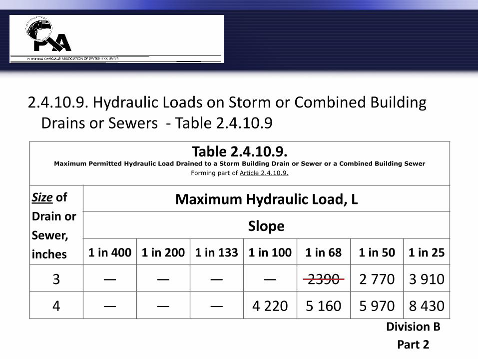
2.4.10.9. Hydraulic Loads on Storm or Combined Building Drains or Sewers - Table 2.4.10.9
Division B
Part 2
Table 2.4.10.9. Maximum Permitted Hydraulic Load Drained to a Storm Building Drain or Sewer or a Combined Building Sewer
Forming part of Article 2.4.10.9.
Size of
Drain or
Sewer,
inches
Maximum Hydraulic Load, L
Slope
1 in 400 1 in 200 1 in 133 1 in 100 1 in 68 1 in 50 1 in 25
3 — — — — 2390 2 770 3 910
4 — — — 4 220 5 160 5 970 8 430
2.5.2.1. Wet Venting
1) A soil-or-waste pipe may serve as a wet vent provided that
a) the hydraulic load is in accordance with Table 2.5.8.1.,
Table 7.5.2.1. (Sizing of Wet Vents in 2006 Code) has been removed from the 2012 Code and all references to Table
7.5.2.1 have been changed to 2.5.8.1)
Division B
Part 2
2.5.2.1. Wet Venting
1) A soil-or-waste pipe may serve as a wet vent provided that
g) the hydraulic load of separately vented fixtures that drain into the wet vent are not included when sizing the continuous vent that serves the wet vent,
( rewording of the clause means the same as before )
Division B
Part 2
2.5.4.2. Vent Stacks
1) Except as provided in Sentence (2), every soil-or-waste stack draining fixtures from more than 4 storeys shall have a vent stack.
Division B
Part 2
2.5.8.3. Branch Vents, Vent Headers, Continuous Vents and Circuit Vents
1) Branch vents, vent headers, circuit vents and continuous vents shall be sized in accordance with Table 2.5.8.3., unless they are individual vents or dual vents.
The size of individual vents and dual vents shall be determined using Table 2.5.7.1. based on the largest
trap served Division B
Part 2
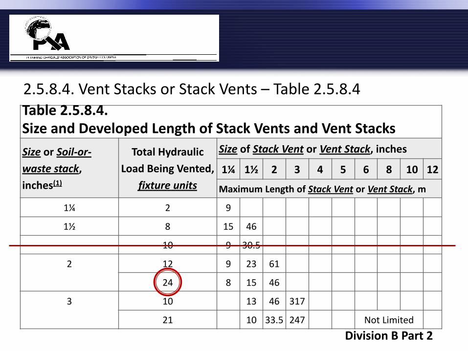
2.5.8.4. Vent Stacks or Stack Vents – Table 2.5.8.4
Table 2.5.8.4. Size and Developed Length of Stack Vents and Vent Stacks
Size or Soil-or-
waste stack,
inches(1)
Total Hydraulic
Load Being Vented,
fixture units
Size of Stack Vent or Vent Stack, inches
1¼ 1½ 2 3 4 5 6 8 10 12
Maximum Length of Stack Vent or Vent Stack, m
1¼ 2 9
1½ 8 15 46
10 9 30.5
2 12 9 23 61
24 8 15 46
3 10 13 46 317
21 10 33.5 247 Not Limited
Division B Part 2
2.6.1.12. Service Water Heaters
1) Thermostat controls for electric storage-type service water heaters shall be set at a temperature of 60°C. (See Appendix A.)
Division B
Part 2
A-2.6.1.12.(1) Service Water Heaters
Storing hot water at temperatures below 60°C in the hot water tank or in the delivery system may lead to the growth of legionella bacteria. Contemporary electric water heater tanks experience temperature stratification and thus tend to have legionella bacteria in the lower parts of the tank.
Division B
Appendix

A-2.6.1.12.(1) Service Water Heaters (cont.)
Article 2.6.1.12. specifies a thermostat setting of 60°C, which addresses the concern over the growth of legionella bacteria in electric hot water storage tanks and is enforceable without introducing unnecessary complications. The growth of legionella bacteria is not a concern for other types of water heaters with different designs that use different fuels.
Division B
Appendix
2.6.3. Size and Capacity of Pipes
2.6.3.1. Design, Fabrication and Installation
1) Every water distribution system shall be designed to provide peak demand flow when the flow pressures at the supply openings conform to the plumbing supply fitting manufacturer’s specifications.
Division B
Part 2
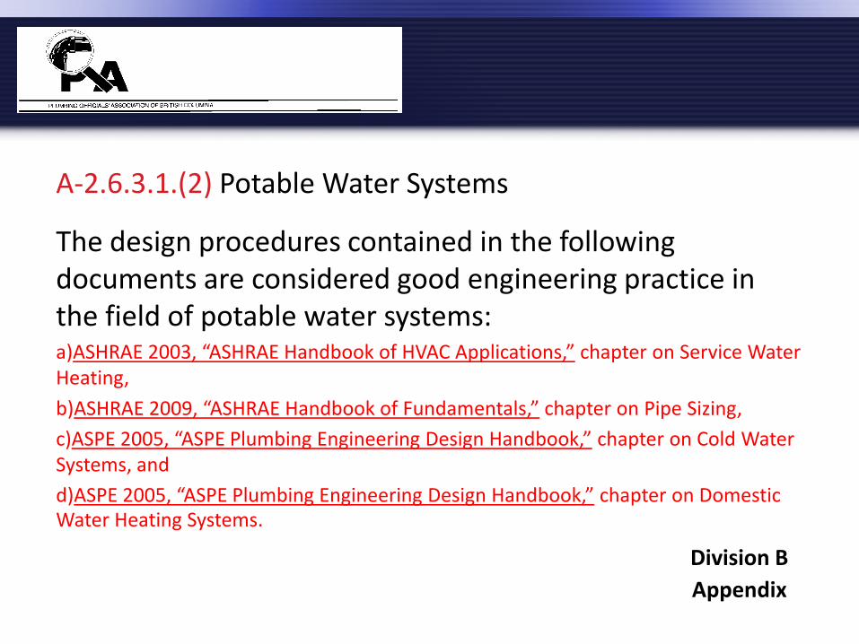
A-2.6.3.1.(2) Potable Water Systems
The design procedures contained in the following documents are considered good engineering practice in the field of potable water systems: a)ASHRAE 2003, “ASHRAE Handbook of HVAC Applications,” chapter on Service Water Heating,
b)ASHRAE 2009, “ASHRAE Handbook of Fundamentals,” chapter on Pipe Sizing,
c)ASPE 2005, “ASPE Plumbing Engineering Design Handbook,” chapter on Cold Water Systems, and
d)ASPE 2005, “ASPE Plumbing Engineering Design Handbook,” chapter on Domestic Water Heating Systems.
Division B
Appendix

A-2.6.3.1.(2) Potable Water Systems (cont.)
Alternatively, the following methods, which apply to both public and private water supplies, may be used in determining the size of each section of the water system using
•Table A-2.6.3.1.(2)A (Small Commercial Building Method) and •Table A-2.6.3.1.(2)F (Average Pressure Loss Method).
Where these methods are considered an alternative to a detailed engineering design method, the hydraulic loads shall be the sum of the total fixture units given in Tables 2.6.3.2.A, B, C and D.
Division B
Appendix
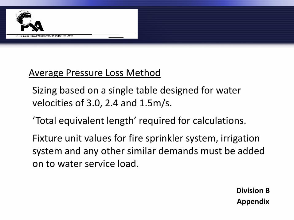
Average Pressure Loss Method
Sizing based on a single table designed for water velocities of 3.0, 2.4 and 1.5m/s.
‘Total equivalent length’ required for calculations.
Fixture unit values for fire sprinkler system, irrigation system and any other similar demands must be added on to water service load.
Division B
Appendix
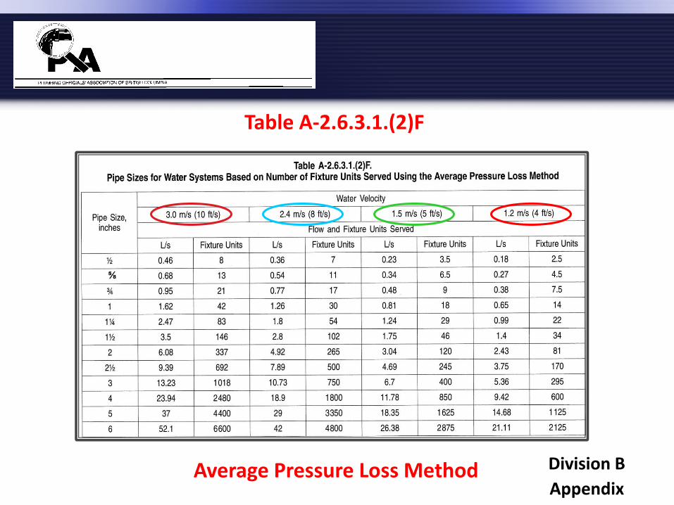
Average Pressure Loss Method
Table A-2.6.3.1.(2)F
Division B
Appendix
Average Pressure Loss Method (cont.)
Pressure losses from devices, meters and elevation must be taken into consideration.
Designed for use in larger commercial, but can be used for any size building.
To use this method, calculate the pressure available for friction loss which must be 2.6 kPa per metre or more; if it is less than that, the system must be designed according to a detailed engineering design method.
Division B Appendix
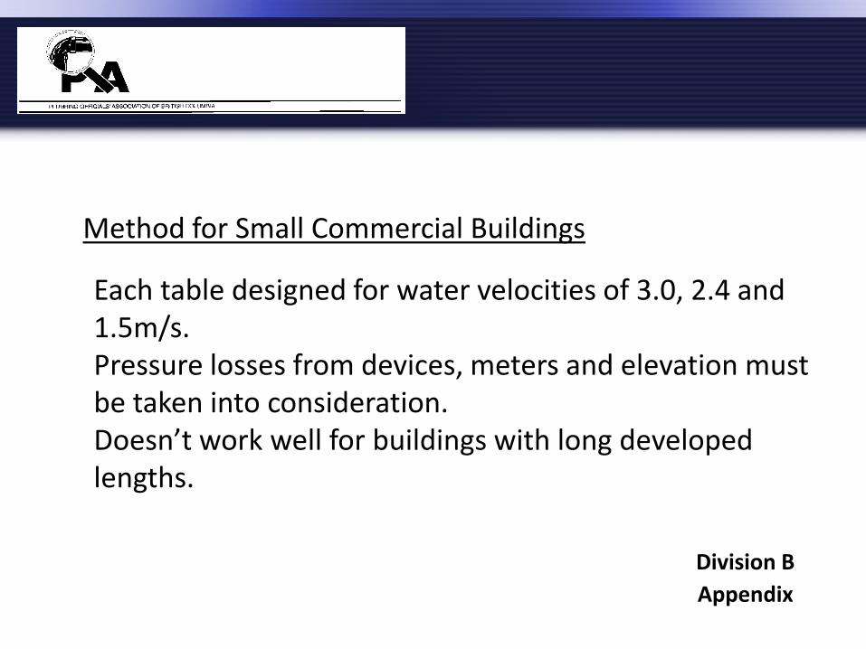
Method for Small Commercial Buildings
Each table designed for water velocities of 3.0, 2.4 and 1.5m/s. Pressure losses from devices, meters and elevation must be taken into consideration. Doesn’t work well for buildings with long developed lengths.
Division B
Appendix

Small Commercial Method
Table A-2.6.3.1.(2)A.
Division B Appendix
2.6.3.1. Design, Fabrication and Installation (cont.)
3) In one- and two-family dwelling units and manufactured homes, multi-purpose systems that combine potable water systems and residential fire sprinkler systems shall be designed, fabricated and installed in accordance with NFPA 13D, “Installation of Sprinkler Systems in One- and Two-Family Dwellings and Manufactured Homes.”
Division B
Part 2
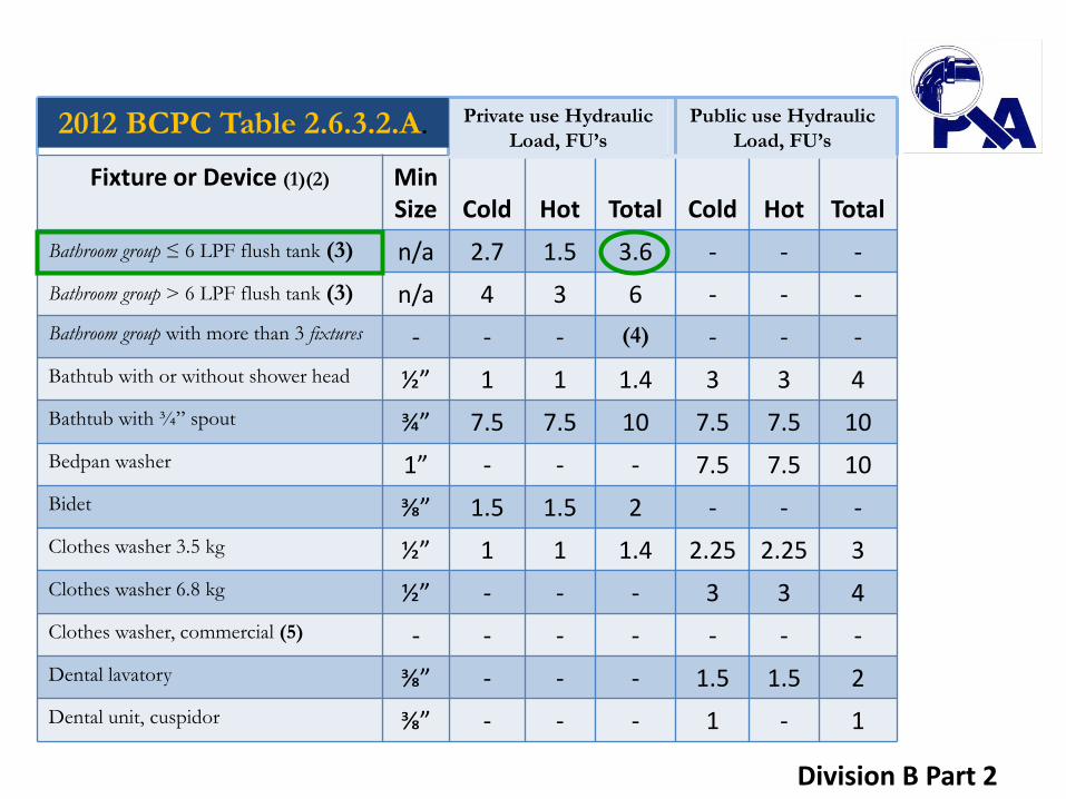
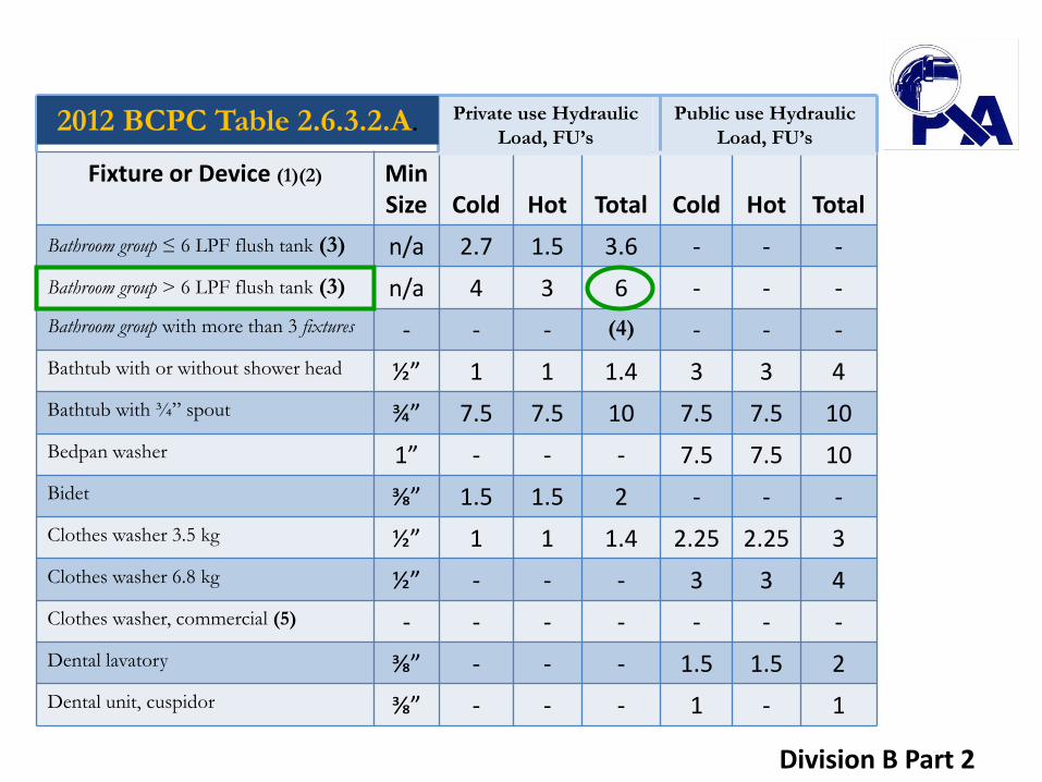
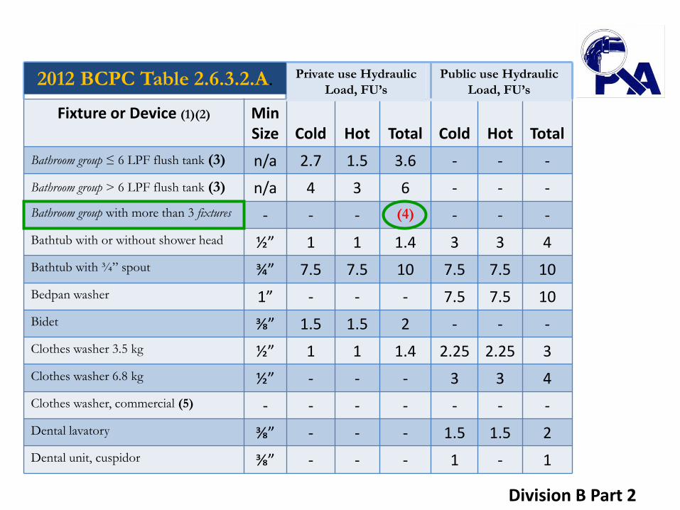
2.6.3.2. Hydraulic Load
1) Except as provided in Sentence (3), the hydraulic load of a fixture or device that is listed in Table 2.6.3.2.A. shall be the number of fixture units given in the Table.
Division B
Part 2
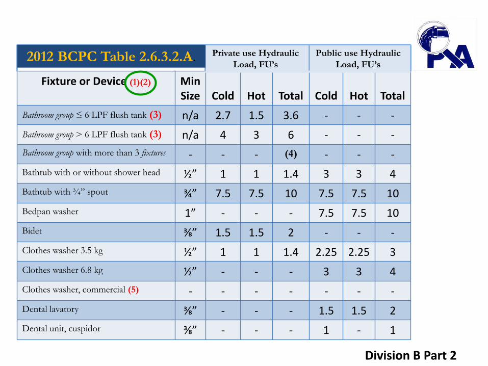
Fixture or Device (1)(2) Min Size
Cold
Hot
Total
Cold
Hot
Total
Bathroom group ≤ 6 LPF flush tank (3) n/a 2.7 1.5 3.6 - - -
Bathroom group > 6 LPF flush tank (3) n/a 4 3 6 - - -
Bathroom group with more than 3 fixtures - - - (4) - - -
Bathtub with or without shower head ½” 1 1 1.4 3 3 4
Bathtub with ¾” spout ¾” 7.5 7.5 10 7.5 7.5 10
Bedpan washer 1” - - - 7.5 7.5 10
Bidet ⅜” 1.5 1.5 2 - - -
Clothes washer 3.5 kg ½” 1 1 1.4 2.25 2.25 3
Clothes washer 6.8 kg ½” - - - 3 3 4
Clothes washer, commercial (5) - - - - - - -
Dental lavatory ⅜” - - - 1.5 1.5 2
Dental unit, cuspidor ⅜” - - - 1 - 1
Private use Hydraulic
Load, FU’s
Public use Hydraulic
Load, FU’s 2012 BCPC Table 2.6.3.2.A.
Division B Part 2
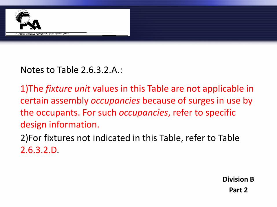
Notes to Table 2.6.3.2.A.:
1)The fixture unit values in this Table are not applicable in certain assembly occupancies because of surges in use by the occupants. For such occupancies, refer to specific design information.
2)For fixtures not indicated in this Table, refer to Table 2.6.3.2.D.
Division B
Part 2
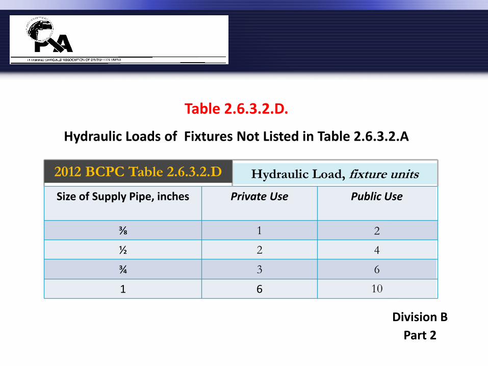
Size of Supply Pipe, inches Private Use Public Use
⅜ 1 2
½ 2 4
¾ 3 6
1 6 10
Hydraulic Load, fixture units 2012 BCPC Table 2.6.3.2.D
Table 2.6.3.2.D.
Hydraulic Loads of Fixtures Not Listed in Table 2.6.3.2.A
Division B
Part 2
Fixture or Device (1)(2) Min Size
Cold
Hot
Total
Cold
Hot
Total
Bathroom group ≤ 6 LPF flush tank (3) n/a 2.7 1.5 3.6 - - -
Bathroom group > 6 LPF flush tank (3) n/a 4 3 6 - - -
Bathroom group with more than 3 fixtures - - - (4) - - -
Bathtub with or without shower head ½” 1 1 1.4 3 3 4
Bathtub with ¾” spout ¾” 7.5 7.5 10 7.5 7.5 10
Bedpan washer 1” - - - 7.5 7.5 10
Bidet ⅜” 1.5 1.5 2 - - -
Clothes washer 3.5 kg ½” 1 1 1.4 2.25 2.25 3
Clothes washer 6.8 kg ½” - - - 3 3 4
Clothes washer, commercial (5) - - - - - - -
Dental lavatory ⅜” - - - 1.5 1.5 2
Dental unit, cuspidor ⅜” - - - 1 - 1
Private use Hydraulic
Load, FU’s
Public use Hydraulic
Load, FU’s 2012 BCPC Table 2.6.3.2.A.
Division B Part 2

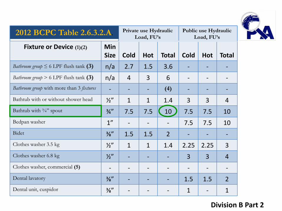
Notes to Table 2.6.3.2.A.(cont.):
3) Bathroom group is based on a ½-inch size bathtub supply pipe.
A bathroom group is a defined term as “a group of plumbing fixtures installed in the same room,
consisting of one domestic-type lavatory, one water closet and either one bathtub (with or without a
shower) or one one-head shower.
Division B
Part 2
Fixture or Device (1)(2) Min Size
Cold
Hot
Total
Cold
Hot
Total
Bathroom group ≤ 6 LPF flush tank (3) n/a 2.7 1.5 3.6 - - -
Bathroom group > 6 LPF flush tank (3) n/a 4 3 6 - - -
Bathroom group with more than 3 fixtures - - - (4) - - -
Bathtub with or without shower head ½” 1 1 1.4 3 3 4
Bathtub with ¾” spout ¾” 7.5 7.5 10 7.5 7.5 10
Bedpan washer 1” - - - 7.5 7.5 10
Bidet ⅜” 1.5 1.5 2 - - -
Clothes washer 3.5 kg ½” 1 1 1.4 2.25 2.25 3
Clothes washer 6.8 kg ½” - - - 3 3 4
Clothes washer, commercial (5) - - - - - - -
Dental lavatory ⅜” - - - 1.5 1.5 2
Dental unit, cuspidor ⅜” - - - 1 - 1
Private use Hydraulic
Load, FU’s
Public use Hydraulic
Load, FU’s 2012 BCPC Table 2.6.3.2.A.
Division B Part 2

Notes to Table 2.6.3.2.A.(cont.):
4) Add additional fixture to the fixture load for bathroom group
Additional fixtures may be added to a bathroom group that meets the definition in 1.4.1.2..
If any other fixtures, beyond those permitted in circumstances that comply with note (4) above, are fed from the piping that leads to a bathroom group, then the fixtures in the bathroom group must be considered individually for
determining the fixture unit load.
Division B Part 2
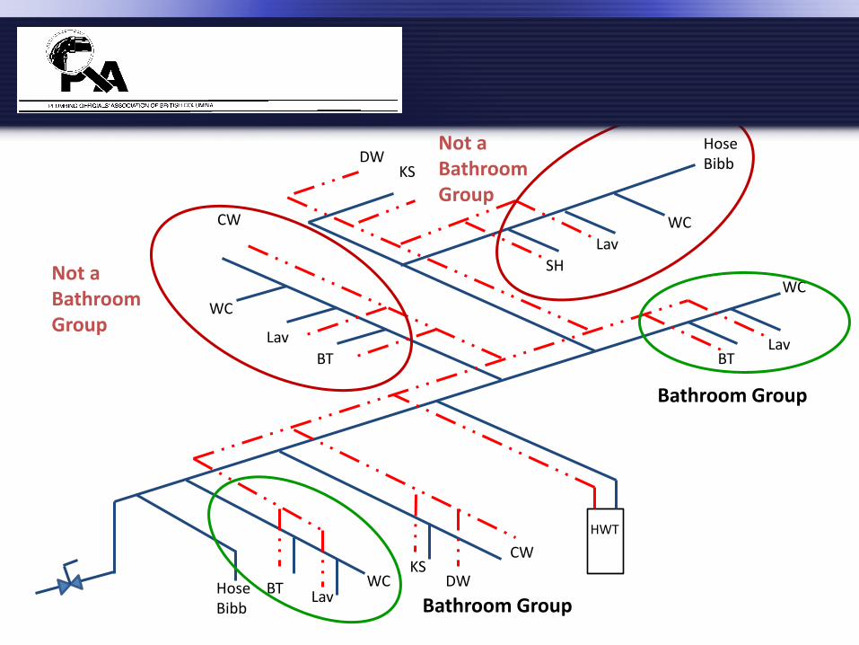
BT Lav
WC Hose Bibb
KS DW
CW
HWT
BT
WC
Lav
BT Lav
WC
SH
Lav
WC
KS DW
Hose Bibb
CW
Not a Bathroom Group
Not a Bathroom Group
Bathroom Group
Bathroom Group
Fixture or Device (1)(2) Min Size
Cold
Hot
Total
Cold
Hot
Total
Bathroom group ≤ 6 LPF flush tank (3) n/a 2.7 1.5 3.6 - - -
Bathroom group > 6 LPF flush tank (3) n/a 4 3 6 - - -
Bathroom group with more than 3 fixtures - - - (4) - - -
Bathtub with or without shower head ½” 1 1 1.4 3 3 4
Bathtub with ¾” spout ¾” 7.5 7.5 10 7.5 7.5 10
Bedpan washer 1” - - - 7.5 7.5 10
Bidet ⅜” 1.5 1.5 2 - - -
Clothes washer 3.5 kg ½” 1 1 1.4 2.25 2.25 3
Clothes washer 6.8 kg ½” - - - 3 3 4
Clothes washer, commercial (5) - - - - - - -
Dental lavatory ⅜” - - - 1.5 1.5 2
Dental unit, cuspidor ⅜” - - - 1 - 1
Private use Hydraulic
Load, FU’s
Public use Hydraulic
Load, FU’s 2012 BCPC Table 2.6.3.2.A.
Division B Part 2
Fixture or Device (1)(2) Min Size
Cold
Hot
Total
Cold
Hot
Total
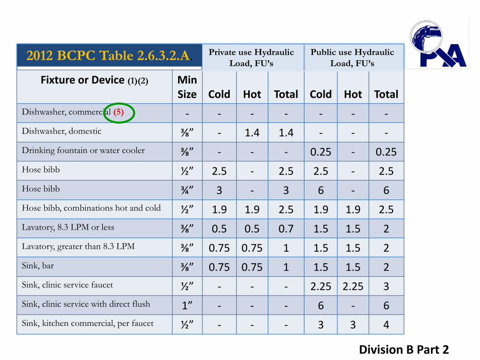
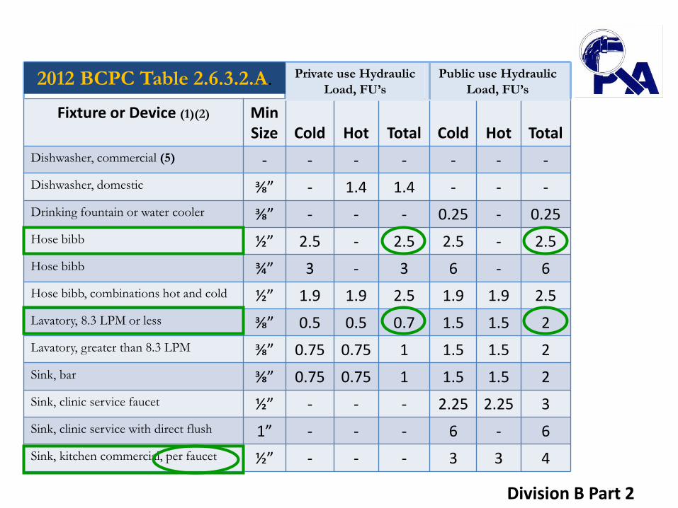
Dishwasher, commercial (5) - - - - - - -
Dishwasher, domestic ⅜” - 1.4 1.4 - - -
Drinking fountain or water cooler ⅜” - - - 0.25 - 0.25
Hose bibb ½” 2.5 - 2.5 2.5 - 2.5
Hose bibb ¾” 3 - 3 6 - 6
Hose bibb, combinations hot and cold ½” 1.9 1.9 2.5 1.9 1.9 2.5
Lavatory, 8.3 LPM or less ⅜” 0.5 0.5 0.7 1.5 1.5 2
Lavatory, greater than 8.3 LPM ⅜” 0.75 0.75 1 1.5 1.5 2
Sink, bar ⅜” 0.75 0.75 1 1.5 1.5 2
Sink, clinic service faucet ½” - - - 2.25 2.25 3
Sink, clinic service with direct flush 1” - - - 6 - 6
Sink, kitchen commercial, per faucet ½” - - - 3 3 4
Private use Hydraulic
Load, FU’s
Public use Hydraulic
Load, FU’s 2012 BCPC Table 2.6.3.2.A.
Division B Part 2

Notes to Table 2.6.3.2.A.(cont.):
5)Refer to manufacturer’s recommendations.
Division B
Part 2
Fixture or Device (1)(2) Min Size
Cold
Hot
Total
Cold
Hot
Total
Dishwasher, commercial (5) - - - - - - -
Dishwasher, domestic ⅜” - 1.4 1.4 - - -
Drinking fountain or water cooler ⅜” - - - 0.25 - 0.25
Hose bibb ½” 2.5 - 2.5 2.5 - 2.5
Hose bibb ¾” 3 - 3 6 - 6
Hose bibb, combinations hot and cold ½” 1.9 1.9 2.5 1.9 1.9 2.5
Lavatory, 8.3 LPM or less ⅜” 0.5 0.5 0.7 1.5 1.5 2
Lavatory, greater than 8.3 LPM ⅜” 0.75 0.75 1 1.5 1.5 2
Sink, bar ⅜” 0.75 0.75 1 1.5 1.5 2
Sink, clinic service faucet ½” - - - 2.25 2.25 3
Sink, clinic service with direct flush 1” - - - 6 - 6
Sink, kitchen commercial, per faucet ½” - - - 3 3 4
Private use Hydraulic
Load, FU’s
Public use Hydraulic
Load, FU’s 2012 BCPC Table 2.6.3.2.A.
Division B Part 2

Fixture or Device (1)(2) Min Size
Cold
Hot
Total
Cold
Hot
Total
Sink, kitchen domestic, 8.3 LPM ⅜” 1 1 1.4 1 1 1.4
Sink, kitchen domestic, > 8.3 LPM ⅜” 1.5 1.5 2 1.5 1.5 2
Sink, laboratory ⅜” - - - 1.5 1.5 2
Sink, laundry, 1 or 2 compartments ⅜” 1 1 1.4 1 1 1.4
Sink, service or mop basin ½” - - - 2.25 2.25 3
Sink, washup, per faucet ½” - - - 1.5 1.5 2
Shower head, 9.5 LPM or less per head ½” 1 1 1.4 3 3 4
Shower head, > 9.5 LPM per head ½” 1.5 1.5 2 3 3 4
Shower, spray, multi-head, FU per head (5) 1 1 1.4 3 3 4
Urinal, with direct flush valve ¾” (6) - (6) (6) - (6)
Urinal, with flush tank ⅜” 3 - 3 3 - 3
Urinal, with self-closing metering valve ½” 2 - 2 4 - 4
Private use Hydraulic
Load, FU’s
Public use Hydraulic
Load, FU’s 2012 BCPC Table 2.6.3.2.A.
Division B Part 2
Notes to Table 2.6.3.2.A.(cont.): 6) For fixture unit values for fixtures with direct flush valves, see Sentence 2.6.3.2.(4) and Tables 2.6.3.2.B and 2.6.3.2.C.
Division B
Part 2
Fixture or Device (1)(2) Min Size
Cold
Hot
Total
Cold
Hot
Total
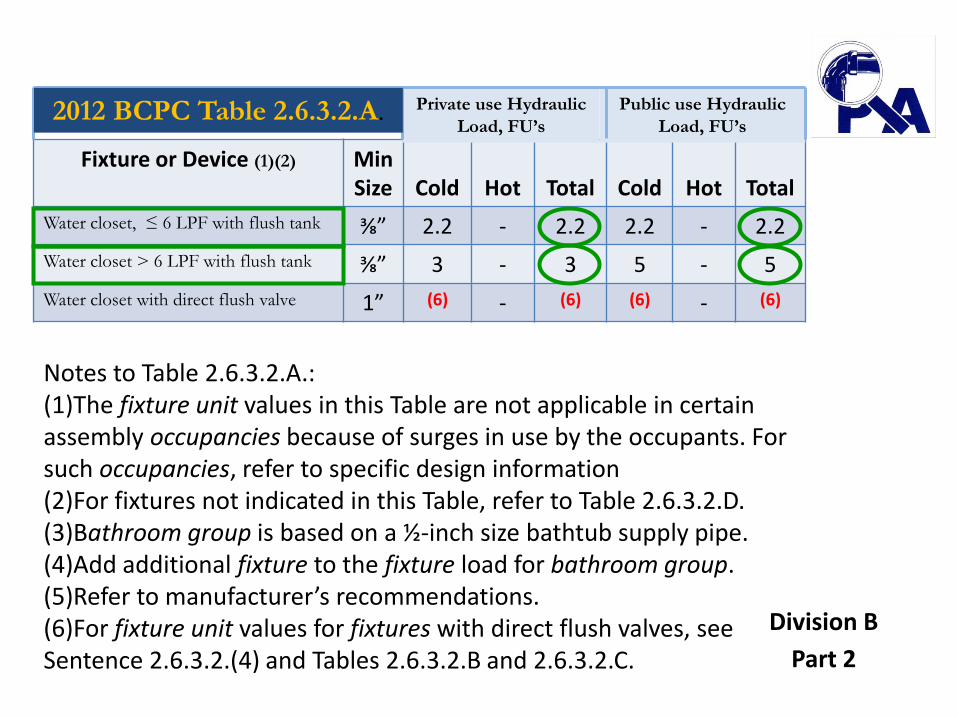
Water closet, ≤ 6 LPF with flush tank ⅜” 2.2 - 2.2 2.2 - 2.2
Water closet > 6 LPF with flush tank ⅜” 3 - 3 5 - 5
Water closet with direct flush valve 1” (6) - (6) (6) - (6)
Private use Hydraulic
Load, FU’s
Public use Hydraulic
Load, FU’s 2012 BCPC Table 2.6.3.2.A.
Notes to Table 2.6.3.2.A.: (1)The fixture unit values in this Table are not applicable in certain assembly occupancies because of surges in use by the occupants. For such occupancies, refer to specific design information (2)For fixtures not indicated in this Table, refer to Table 2.6.3.2.D. (3)Bathroom group is based on a ½-inch size bathtub supply pipe. (4)Add additional fixture to the fixture load for bathroom group. (5)Refer to manufacturer’s recommendations. (6)For fixture unit values for fixtures with direct flush valves, see Sentence 2.6.3.2.(4) and Tables 2.6.3.2.B and 2.6.3.2.C.
Division B
Part 2
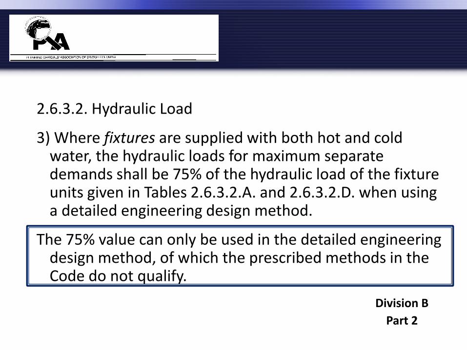
2.6.3.2. Hydraulic Load
3) Where fixtures are supplied with both hot and cold water, the hydraulic loads for maximum separate demands shall be 75% of the hydraulic load of the fixture units given in Tables 2.6.3.2.A. and 2.6.3.2.D. when using a detailed engineering design method.
The 75% value can only be used in the detailed engineering design method, of which the prescribed methods in the Code do not qualify.
Division B
Part 2
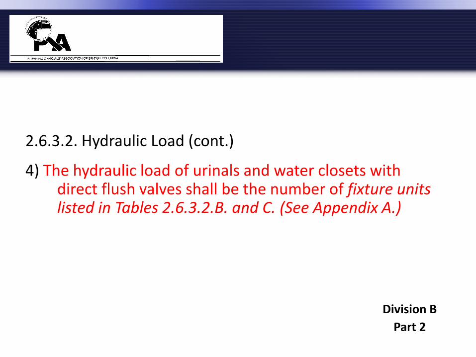
2.6.3.2. Hydraulic Load (cont.)
4) The hydraulic load of urinals and water closets with direct flush valves shall be the number of fixture units listed in Tables 2.6.3.2.B. and C. (See Appendix A.)
Division B
Part 2
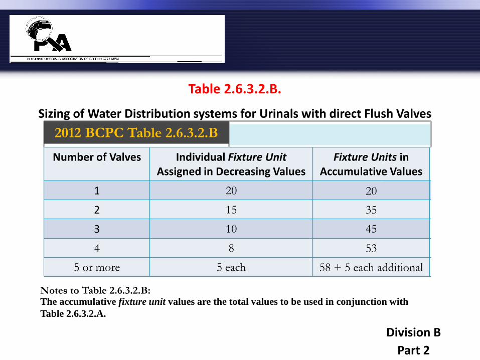
Table 2.6.3.2.B.
Sizing of Water Distribution systems for Urinals with direct Flush Valves
Notes to Table 2.6.3.2.B:
Number of Valves Individual Fixture Unit Assigned in Decreasing Values
Fixture Units in Accumulative Values
1 20 20
2 15 35
3 10 45
4 8 53
2012 BCPC Table 2.6.3.2.B
5 or more 5 each 58 + 5 each additional
The accumulative fixture unit values are the total values to be used in conjunction with
Table 2.6.3.2.A.
Division B
Part 2
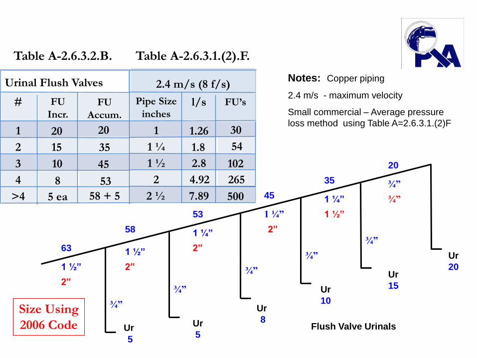
Notes: Copper piping
2.4 m/s - maximum velocity
Small commercial – Average pressure
loss method using Table A=2.6.3.1.(2)F
Flush Valve Urinals Ur
Ur
Ur
Ur
Ur
Ur
5
63
58
53
45
35
20
5
8
10
15
20
¾”
¾”
1 ½”
1 ½”
1 ¼” ¾”
¾”
¾”
1 ¼”
1 ¼”
¾”
2”
2”
1 ½”
2”
2”
¾”
# FU
Incr.
FU
Accum.
1 20 20
2 15 35
3 10 45
4 8 53
>4 5 ea 58 + 5
Urinal Flush Valves
Pipe Size
inches
1 1.26 30
1 ¼ 1.8 54
1 ½ 2.8 102
2 4.92 265
2.4 m/s (8 f/s)
l/s
FU’s
7.89 500 2 ½
Table A-2.6.3.1.(2).F.
Size Using
2006 Code
Table A-2.6.3.2.B.

Table 2.6.3.2.C.
Sizing of Water Distribution systems for Water Closets with direct Flush Valves
Notes to Table 2.6.3.2.C:
Number of Valves Individual Fixture Unit Assigned in Decreasing Values
Fixture Units in Accumulative Values
1 40 40
2 30 70
3 20 90
4 15 105
2012 BCPC Table 2.6.3.2.C
5 or more
10 for each public use
and
6 for each private use
115 + 10 for each public use
and
111 + 6 for each private use
The accumulative fixture unit values are the total values to be used in conjunction with
Table 2.6.3.2.A.
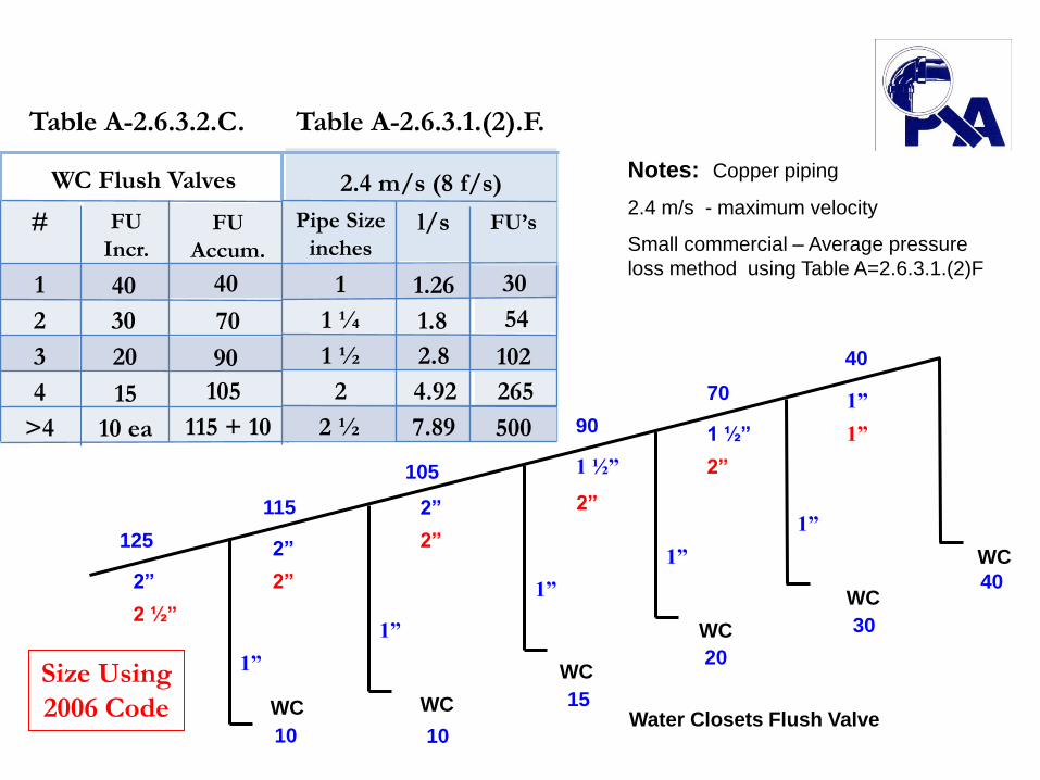
Notes: Copper piping
2.4 m/s - maximum velocity
Small commercial – Average pressure
loss method using Table A=2.6.3.1.(2)F
Water Closets Flush Valve WC
WC
WC
WC
WC
WC
10
125
115
105
90
70
40
10
15
20
30
40
1”
1”
2”
2”
2” 1”
1”
1”
1 ½”
1 ½”
1”
2 ½”
2”
2”
2”
2”
1”
# FU
Incr.
FU
Accum.
1 40 40
2 30 70
3 20 90
4 15 105
>4 10 ea 115 + 10
WC Flush Valves
Table A-2.6.3.1.(2).F.
Size Using
2006 Code
Table A-2.6.3.2.C.
Pipe Size
inches
1 1.26 30
1 ¼ 1.8 54
1 ½ 2.8 102
2 4.92 265
2.4 m/s (8 f/s)
l/s
FU’s
7.89 500 2 ½
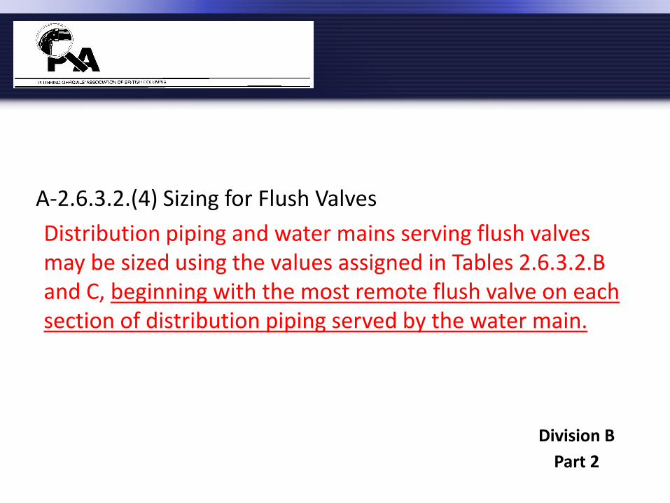
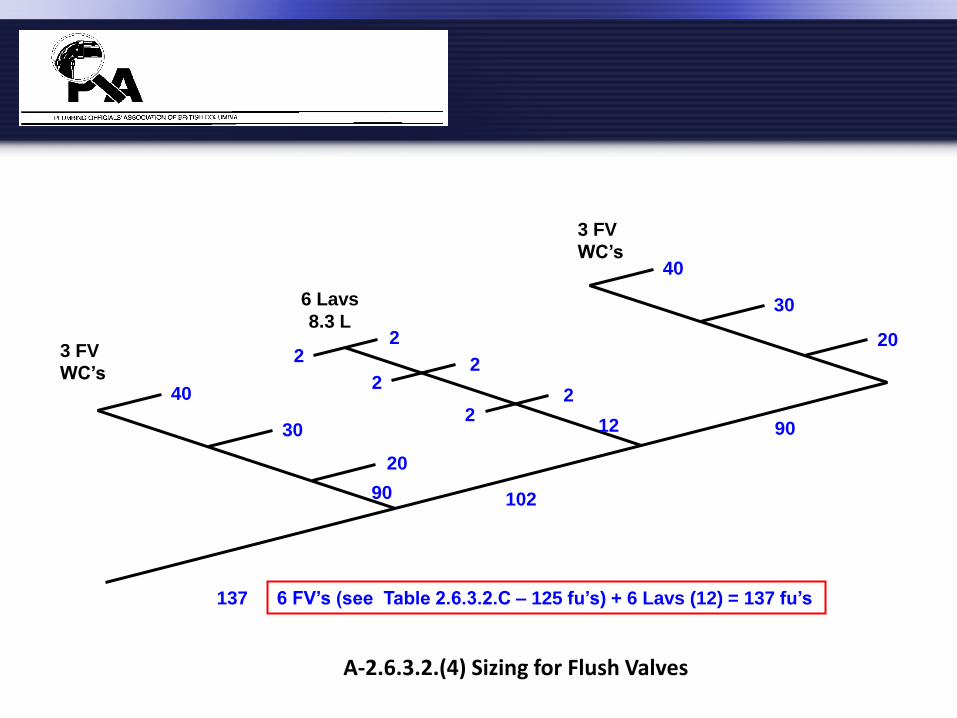
A-2.6.3.2.(4) Sizing for Flush Valves
Distribution piping and water mains serving flush valves may be sized using the values assigned in Tables 2.6.3.2.B and C, beginning with the most remote flush valve on each section of distribution piping served by the water main.
Division B
Part 2
3 FV
WC’s
6 Lavs
8.3 L
90 102
40
20
30
40
3 FV
WC’s
2 2 2
2 2
2
30
20
90 12
137
A-2.6.3.2.(4) Sizing for Flush Valves
6 FV’s (see Table 2.6.3.2.C – 125 fu’s) + 6 Lavs (12) = 137 fu’s

2.6.3.4. Size
2) Except as provided in Sentence (3), the size of a supply pipe that serves a fixture shall conform to Table 2.6.3.2.A.
3) For fixtures listed in Table 2.6.3.2.A. that have a permitted supply pipe size of 3/8 inch, a connector not more than 750 mm long and not less than 6.3 mm inside diameter may be used to supply water to the fixture.
Division B
Part 2
2.6.3.4. Size (cont.)
(5) Where both hot and cold water is supplied to fixtures in residential buildings containing one or two dwelling units or row houses with separate water service pipes, the water system may be sized in accordance with Table 2.6.3.4. where:
Division B
Part 2

2.6.3.4.(5) (cont.)
a) the hydraulic loads for maximum separate demands on water distribution system piping are not less than 100% of the total hydraulic load of the fixture units given in Tables 2.6.3.2.A, B, C or D for private use,
b) the minimum water pressure at the entry to the building is 200 kPa, and
c) the total maximum length of water system is 90 m.
Division B
Part 2

Table 2.6.3.4. Water Pipe Sizing for Buildings Containing One or Two Dwelling Units or Row
Houses with Separate Water Service Pipes
Forming Part of Sentence 2.6.3.4.(5)
Note to Table 2.6.3.4.:
(1) Table 2.6.3.4. is not intended to limit water velocities that are specified in Sentence 2.6.3.5.(1).
Size of
Water
Pipe,
Inches
3.0 2.4 1.5
Hydraulic Load, fixture units
Water Velocity, m/s
½”
¾”
1”
1 ¼ ”
8 7 4
9 21 16
43 31
83
18
57 30
1.5 m/s = 5 ft/s 2.4 m/s = 8 ft/s 3.0 m/s = 10 ft/s
Division B
Part 2
(1)
Notes to Table 2.6.3.4.:
Table 2.6.3.4. is not intended to limit water velocities that are permitted by Sentence 2.6.3.5.(1).
Division B
Part 2
2.6.3.5. Velocity
1) The maximum permitted water velocities shall be those recommended by the pipe and fitting manufacturer.
Division B
Part 2
Section 2.7. Non-Potable Water Systems
2.7.2.1. Markings Required
(1) The location of non-potable water discharge and non-potable water piping shall be identified by markings that are permanent, distinct and easily recognized.
Division B
Part 2
A-2.7.3.2.(1) Outlets from Non-Potable Water Systems
The location of outlets from non-potable water systems where they can be discharged into a sink or lavatory (i.e. bathroom sink), a fixture into which an outlet from a potable water system is discharged, or a fixture that is used for the preparation, handling or dispensing of food, drink or products that are intended for human consumption, may have proven acceptable on the basis of past performance in some localities such as rest stops, and its acceptance under this Code may be warranted.
Division B
Appendix

A-2.7.3.2.(1) Outlets from Non-Potable Water Systems (cont.)
Subclause 2.7.3.2.(1)(b) would permit non potable water to be used to supply water closets or urinals provided the fixtures are not also connected to potable water.
Division B
Appendix
2.7.4.1. Non-potable Water System Design (See Appendix A.)
1) Non-potable water systems shall be designed, fabricated and installed in accordance with good engineering practice, such as that described in the ASHRAE Handbooks, ASPE Handbooks and CAN/CSA-B128.1, “Design and Installation of Non-Potable Water Systems.”
Division B
Part 2
A-2.7.4.1. Non-potable Water System Design
There is a growing interest in Canada in using available non-potable water supplies in the place of potable ones for selected purposes such as flushing toilets and irrigating lawns and gardens. Article 2.7.4.1. applies to non-potable water systems regardless of the origin of the water. The non-potable water must meet applicable water quality standards as determined by an authority having jurisdiction.
Division B
Appendix
Good engineering practice would dictate that non-potable water be of appropriate quality for the end use. The Canadian Guidelines for Domestic Reclaimed Water for Use in Toilet and Urinal Flushing, as published by Health Canada, provides appropriate water quality values for those uses. Water quality values and monitoring requirements for reclaimed water are also prescribed by a regulation made under the Environmental Management Act (EMA). Reclaimed water is a subset of non-potable water, produced from larger volume systems accepting domestic or municipal wastewater. Division B
Appendix
Consequently, the monitoring requirements may be more stringent than necessary for smaller applications, but the water quality values may still be taken in isolation and used as a benchmark for non-potable water systems designed to meet 2.7.4.1. to which the regulation under the EMA does not apply. The water quality values can include biochemical oxygen demand (BOD5), turbidity (NTU) and fecal coliforms.
Division B
Appendix
Note that the regulation under the EMA permits additional uses for non-potable water under certain conditions. It is not the intent of Section 2.7. to contradict the EMA or its regulations, but rather, to regulate the end use of non-potable water systems where the EMA does not apply.
Division B
Appendix

Appendix A Explanatory Material
This Appendix is included for explanatory purposes only and does not form part of the requirements. The numbers that introduce each Appendix Note correspond to the applicable requirements in this Division. The figures are schematic only; they depict various parts of the plumbing system but do not include details. For an explanation of the symbols and abbreviations used in the figures, refer to the list provided at the end of the Code.
Division B
Appendix

Division C
Division C
Part 1 – General
Part 2 – Administrative Provisions
Appendix A (Division C)

2.2.1.2. Personnel Performing Plumbing Work
1) Personnel performing installation, alteration or repair on a plumbing system shall
a) possess a British Columbia tradesman's qualification certification as a plumber,
b) be an indentured apprentice supervised by a journeyman possessing a British Columbia tradesman's qualification certification as a plumber, or
Division C
Part 2
2.2.2. PLUMBING DRAWINGS AND RELATED DOCUMENTS
2.2.2.1. Information Required on Plumbing Drawings and Related Documents
1) If the authority having jurisdiction legally requires an application for a permit in respect of plumbing systems, plumbing drawings and related documents submitted with the application for a plumbing permit shall show
Division C
Part 2
2.2.2.1.(1) Information Required on Plumbing Drawings and Related Documents (cont.)
a) the location and size of every building drain and of every trap and cleanout fitting that is on a building drain,
b) the size and location of every soil-or-waste pipe, trap and vent pipe, and
c) a layout of the potable water distribution system, including pipe sizes and valves.
Division C
Part 2

2.3.1. ALTERNATIVE SOLUTIONS
2.3.1.1. Application
1) For the purposes of Clause 1.2.1.1.(1)(b) of Division A, on written request by the owner of a building or an authorized agent of that owner, the authority having jurisdiction shall accept a measure as an alternative solution to an acceptable solution for the building if satisfied that
Division C
Part 2

2.3.1.1. Application (cont.)
a) the measure will achieve at least the level of performance required by Clause 1.2.1.1.(1)(b) of Division A, and
b) the acceptable solution does not expressly require conformance to a provincial enactment other than the British Columbia Building Code.
Division C
Part 2
2.3.1.2.(2) Documentation
b) information concerning any special maintenance or operation requirements, including any plumbing system component commissioning requirements, that are necessary for the alternative solution to achieve compliance with the Code after the plumbing system is installed.
Division C
Part 2
2.3.1.2. Documentation (cont.)
6) Where more than one person is responsible for the design of a plumbing system, a building or facility that includes a proposed alternative solution, the person requesting the use of the alternative solution shall identify a single person to coordinate the preparation of the design, Code analysis and documentation referred to in this Article.
Division C
Part 2

Part 10 – Energy and Water Efficiency
Section 10.3 Water Efficiency
10.3.1.2. Fixture Efficiency
2012 Code did not carry forward the requirement s for high efficiency flush water closets (4.8 lpf) under Article 10.3.1.2. introduced in October 2011. This was an oversight and will be addressed by an amendment shortly.
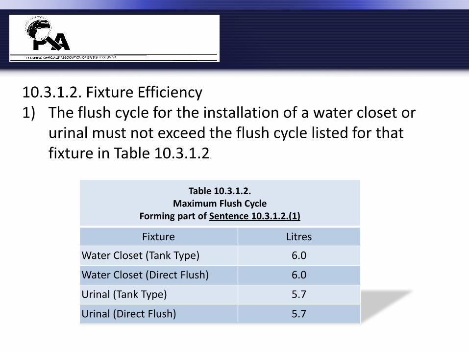
Table 10.3.1.2. Maximum Flush Cycle
Forming part of Sentence 10.3.1.2.(1)
Fixture Litres
Water Closet (Tank Type) 6.0
Water Closet (Direct Flush) 6.0
Urinal (Tank Type) 5.7
Urinal (Direct Flush) 5.7
10.3.1.2. Fixture Efficiency 1) The flush cycle for the installation of a water closet or
urinal must not exceed the flush cycle listed for that fixture in Table 10.3.1.2.

Table 10.3.1.2. Maximum Flush Cycle
Forming part of Sentence 10.3.1.2.(2)
Fixture Litres
Water Closet (Tank Type) 4.8(1)
Water Closet (Direct Flush) 6.0
Urinal (Tank Type) 5.7
Urinal (Direct Flush) 5.7
10.3.1.2. Fixture Efficiency 2) The flush cycle for the installation of a water closet or
urinal in buildings classified as group C must not exceed the flush cycle listed for that fixture in Table 10.3.1.2.(2).
Notes to Table 10.3.1.2. (1) A water closet which provides a dual flush cycle option of both 4.1 L or less and 6.0 L shall be deemed to comply.
Index
Symbols and Abbreviations – Table Added
Conversion Factors - Expanded

2012
British Columbia
Plumbing Code
Update


![t m s environment ltd · TMS Environment Ref. 23562 Appendix I Appendix1:1 – Stack Diagram A1 Appendix1:2 - Stack Information Emission Point Vent A1 Stack Length [m] 0.6 Stack Length](https://static.fdocuments.in/doc/165x107/5ebee0994b706e1ebe7dcf2c/t-m-s-environment-tms-environment-ref-23562-appendix-i-appendix11-a-stack-diagram.jpg)