2012 Bridges Kevin Drain
19
20 12 E x am inat ion – Quest ion No 3 2012 Bridges Question Road Bridge Over River Sample Solution
-
Upload
scribdcwpm -
Category
Documents
-
view
220 -
download
0
Transcript of 2012 Bridges Kevin Drain

7/28/2019 2012 Bridges Kevin Drain
http://slidepdf.com/reader/full/2012-bridges-kevin-drain 1/19
2012 Examination – Question No 3
2012 Bridges Question
Road Bridge Over River
Sample Solution
7/28/2019 2012 Bridges Kevin Drain
http://slidepdf.com/reader/full/2012-bridges-kevin-drain 2/19
Presentation Outline
• The Problem – River Bridge
• Dissecting The 2012 Bridges Question
• Section 1(a) – 2 Distinct Solutions
• Section 1(b) – Client Letter
• Section 2 (c) – Design Calculations
• Section 2 (d) – Drawing
• Section 2 (e) - Method Statement &Programme

7/28/2019 2012 Bridges Kevin Drain
http://slidepdf.com/reader/full/2012-bridges-kevin-drain 3/19
2012 Bridges Question – The Problem

7/28/2019 2012 Bridges Kevin Drain
http://slidepdf.com/reader/full/2012-bridges-kevin-drain 4/19
2012 Bridges Question – The Problem

7/28/2019 2012 Bridges Kevin Drain
http://slidepdf.com/reader/full/2012-bridges-kevin-drain 5/19
2012 Bridges Question – The Problem
Morning SessionWorks
Afternoon SessionWorks
7/28/2019 2012 Bridges Kevin Drain
http://slidepdf.com/reader/full/2012-bridges-kevin-drain 6/19
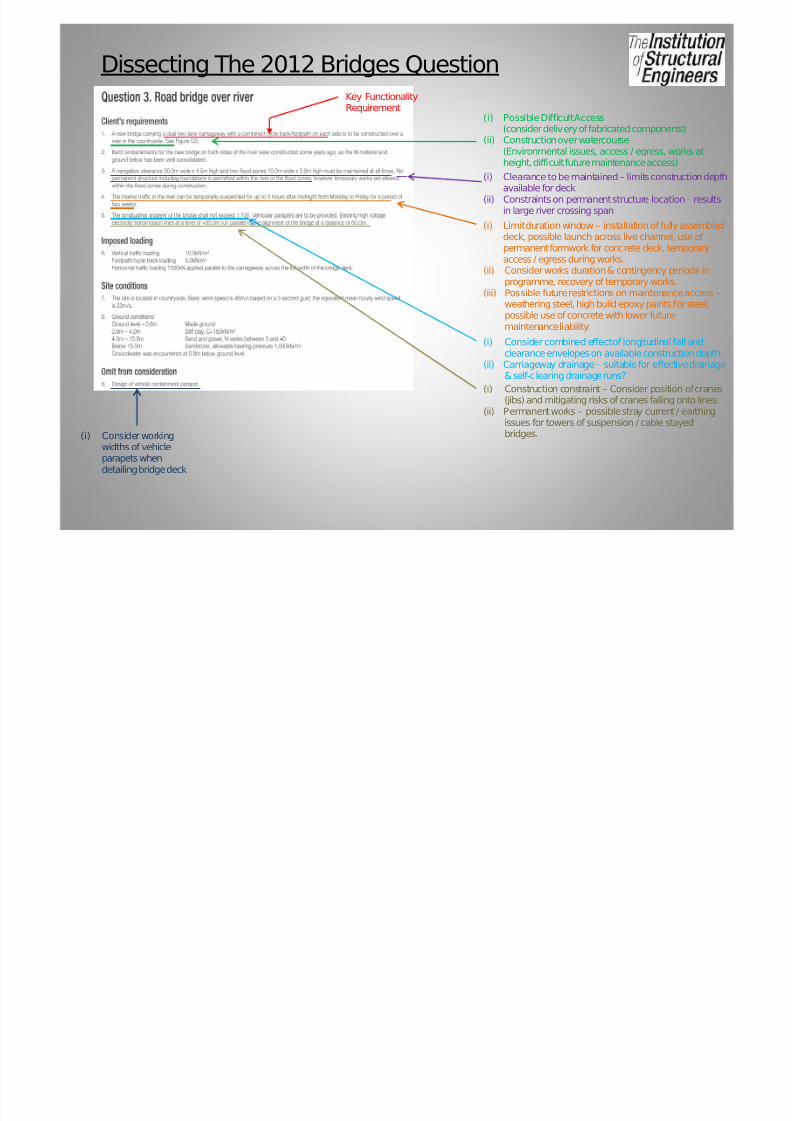
Dissecting The 2012 Bridges Question
Key FunctionalityRequirement
(i) Possible Difficult Access(consider delivery of fabricated components)
(ii) Construction over watercourse(Environmental issues, access / egress, works atheight, difficult future maintenance access)
(i) Clearance to be maintained – limits construction depthavailable for deck
(ii) Constraints on permanent structure location – resultsin large river crossing span
(i) Limit duration window – installation of fully assembleddeck, possible launch across live channel, use of permanent formwork for concrete deck, temporaryaccess / egress during works.
(ii) Consider works duration & contingency periods inprogramme, recovery of temporary works.
(iii) Possible future restrictions on maintenance access –weathering steel, high build epoxy paints for steel,possible use of concrete with lower futuremaintenance liability.
(i) Consider combined effect of longitudinal fall andclearance envelopes on available construction depth.
(ii) Carriageway drainage – suitable for effective drainage& self-clearing drainage runs?
(i) Construction constraint – Consider position of cranes(jibs) and mitigating risks of cranes falling onto lines.
(ii) Permanent works – possible stray current / earthingissues for towers of suspension / cable stayedbridges.(i) Consider working
widths of vehicleparapets whendetailing bridge deck
7/28/2019 2012 Bridges Kevin Drain
http://slidepdf.com/reader/full/2012-bridges-kevin-drain 7/19
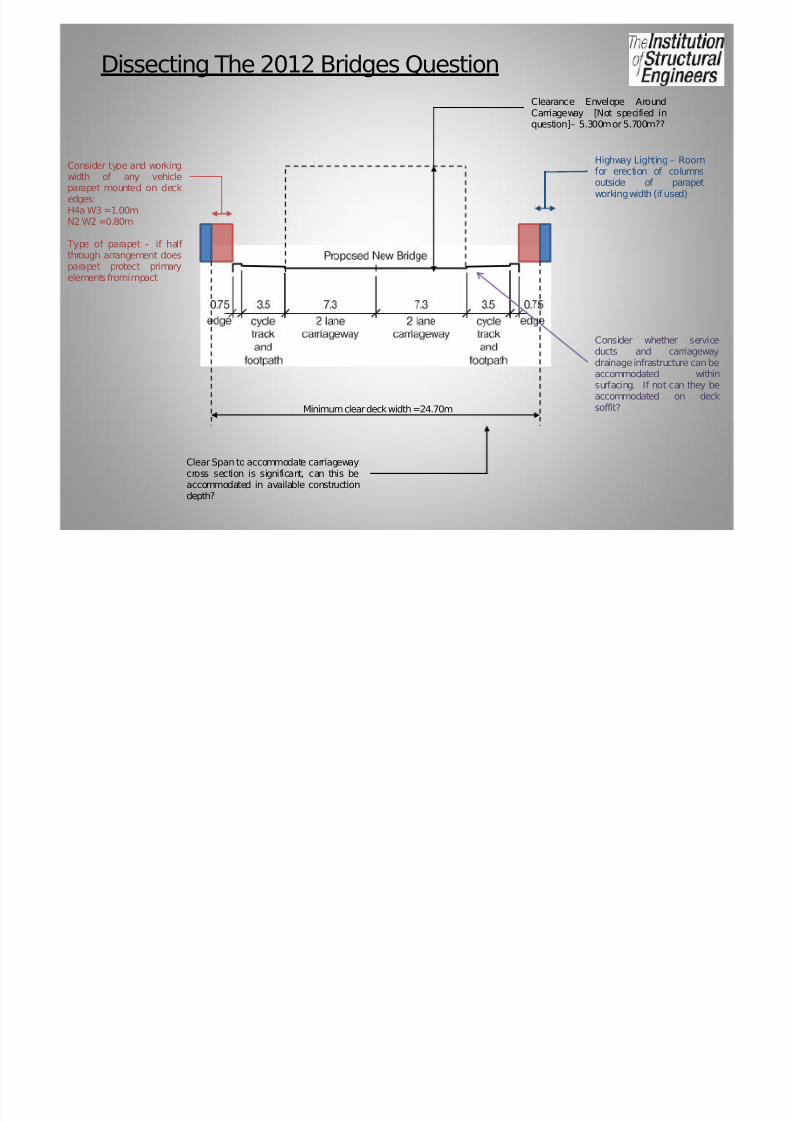
Dissecting The 2012 Bridges Question
Clearance Envelope AroundCarriageway [Not specified inquestion]– 5.300mor5.700m??
Consider type and workingwidth of any vehicleparapet mounted on deckedges:H4a W3 =1.00mN2 W2 =0.80m
Type of parapet – if half through arrangement doesparapet protect primary
elements fromimpact
Highway Lighting – Roomfor erection of columnsoutside of parapetworkingwidth (ifused)
Minimum clear deck width =24.70m
Clear Span toaccommodate carriagewaycross section is significant, can this beaccommodated in available constructiondepth?
Consider whether serviceducts and carriagewaydrainageinfrastructure canbeaccommodated withinsurfacing. If not can they beaccommodated on decksoffit?

7/28/2019 2012 Bridges Kevin Drain
http://slidepdf.com/reader/full/2012-bridges-kevin-drain 8/19
Section 1(a) – Cable Stay Option
• Scheme 2 - Balanced Cable Stay Bridge with existing embankments cut back to balance spans.
Modular steel deck to reduce loads and increase pre-fabrication (limited possessions).
High tower foundation loads transmitted into bed rock – consider pile group effects.

7/28/2019 2012 Bridges Kevin Drain
http://slidepdf.com/reader/full/2012-bridges-kevin-drain 9/19
Section 1(a) – Cable Stay Option
• Scheme 2 - Balanced Cable Stay Bridge with existing embankments cut back to balance spans.
Modular steel deck to reduce loads and increase pre-fabrication (limited possessions).
High tower foundation loads transmitted into bed rock – consider pile group effects.

7/28/2019 2012 Bridges Kevin Drain
http://slidepdf.com/reader/full/2012-bridges-kevin-drain 10/19
Section 1(a) – Cable Stay Option
• Scheme 2 - Balanced Cable Stay Bridge with existing embankments cut back to balance spans.
Modular steel deck to reduce loads and increase pre-fabrication (limited possessions).
High tower foundation loads transmitted into bed rock – consider pile group effects.

7/28/2019 2012 Bridges Kevin Drain
http://slidepdf.com/reader/full/2012-bridges-kevin-drain 11/19
Section 1(a) – Truss Option
• Scheme 2 - 3 Span Truss supported on pile intermediate piers and bankseats.
Centre span of 80m necessitates deep truss.
Depth of truss prohibits use of U-frame action, use discreet restraints to compression flange.
Highway cross section necessitates use of plate girder cross girders with intermediate restraints.

7/28/2019 2012 Bridges Kevin Drain
http://slidepdf.com/reader/full/2012-bridges-kevin-drain 12/19
Section 1(a) – Truss Option
• Scheme 2 - 3 Span Truss supported on pile intermediate piers and bankseats.
Centre span of 80m necessitates deep truss.
Depth of truss prohibits use of U-frame action, use discreet restraints to compression flange.
Highway cross section necessitates use of plate girder cross girders with intermediate restraints.

7/28/2019 2012 Bridges Kevin Drain
http://slidepdf.com/reader/full/2012-bridges-kevin-drain 13/19
Section 1(a) – Truss Option
• Scheme 2 - 3 Span Truss supported on pile intermediate piers and bankseats.
Centre span of 80m necessitates deep truss.
Depth of truss prohibits use of U-frame action, use discreet restraints to compression flange.
Highway cross section necessitates use of plate girder cross girders with intermediate restraints.

7/28/2019 2012 Bridges Kevin Drain
http://slidepdf.com/reader/full/2012-bridges-kevin-drain 14/19
Section 1(a) – Evaluation & RecommendationEval uati on Cri teri a Mu lti-span Truss Op ti on Cabl e St ayed Op ti on
Buildability • Pre-fabrication on river banks will enableinstallation in single possession, 2nd possessionfor
removalof anytemporarywalkways toelevations.• Back spans can be constructed outside of
possession.• Noworks withinriveror floodzones.• High crainage loads if centre span installed in
single / tandemlift.• Concrete pouroverchannel carries risk of pollution
event.
• Modular construction of deck will involve multiplepossessions of river.
• To achieve balance construction work on back and mainspans to be undertaken concurrently.
• Reduced crainagerequirements.
Programme • Minimal possessions required for construction,works largely undertaken outside of navigationchannel.
• Centre span installation weather dependant due to
likelytandemliftrequirement.
• Deck construction critical path fixed to available workingperiodsovernavigationchannel.
Aesthetics • Visually intrusive. • Land-mark structure
Durability /Maintainability
• Use of weathering steel would eliminate significantmaintenanceliabilitybutdouble steelwork costs.
• Use of high buildepoxy paints would maximise lifeto major maintenance to 30-40 years but futuremajormaintenanceworks challenging.
• Routine inspection may necessitate provision of permanentinspectiongantry.
• Use of weathering steel would eliminate significantmaintenanceliabilitybutdouble steelwork costs.
• Useof high build epoxy paints wouldmaximiselife tomajormaintenance to 30-40 years but future major maintenanceworks challenging.
• Routine inspectionmay necessitateprovisionof permanentinspectiongantry.
• Suspension cables in humid environment may result in
long term maintenance liability.
Effect on Channel /Aperture
No effect, aperture largely maintained by both options
Foundation Loads • Imposedloads less than cable stayed option butpiled foundation still required.
• High foundation loads beneath tower.
Candidates to recommend one option with justif ication
7/28/2019 2012 Bridges Kevin Drain
http://slidepdf.com/reader/full/2012-bridges-kevin-drain 15/19
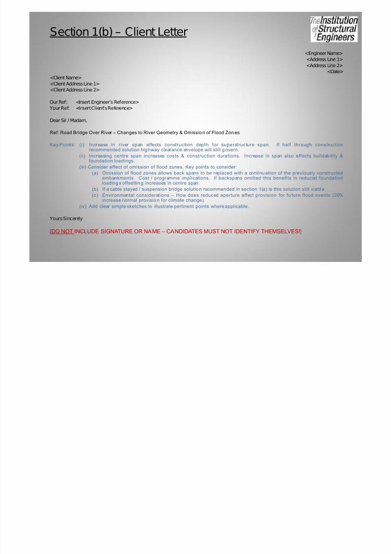
Section 1(b) – Client Letter
<Engineer Name>
<Address Line 1>
<Address Line 2>
<Date>
<Client Name>
<Client Address Line 1>
<Client Address Line 2>
Our Ref: <Insert Engineer’s Reference>
Your Ref: <Insert Client’s Reference>
Dear Sir / Madam,
Ref: Road Bridge Over River – Changes to River Geometry & Omissio n of Flood Zon es
Key Points: (i) Increase in river span affects construction depth for superstructure span. If half through constructionrecommended solution hig hway clearance envelope will still g overn.
(ii) Increasing centre span increases costs & construction durations. Increase in span also affects buildability &foundation loadings.
(iii) Consider effect of omission of flood zones. Key points to consider:
(a) Omission of flood zones allows back spans to be replaced with a continu ation of the previously constructedembankments. Cost / programme implications. If backspans omitted this benefits in reduced foundationloading s offsettin g increases in centre span.
(b) If a cable stayed / suspension bridge solutio n recommended in section 1(a) is this solution still viabl e.
(c) Environmental considerations – How does reduced aperture affect provision for fu ture flood events (20%increase normal provisio n for climate change).
(iv) Add clear simple sketches to illustrate pertinent points where applicable.
Yours Sincerely
[DO NOT INCLUDE SIGNATURE OR NAME – CANDIDATES MUST NOT IDENTIFY THEMSELVES!]

7/28/2019 2012 Bridges Kevin Drain
http://slidepdf.com/reader/full/2012-bridges-kevin-drain 16/19
Section 2(c) – Design Calculations
• Prepare preliminary sizing calculations for all primary elements.
• Avoid repetitive calculations (i.e. avoid design of two similar plate girders).
• Include all assumptions, loading take-offs and lateral / sway loads.• Consider construction stage effects.
• For bridges:
Compos iteBridge Truss Bridge Reinforced Concrete
Bridge
Pre / Post-tensioned
Bridge
Suspension / Cable
Stayed
Concrete Deck Slab Plate Girder Deck Deck Slab Beam Type & Details Deck Section
Cross Girder /Diaphragms
Cross Girder Parapet Plinths Stressing Load /Pattern
Cable Hangers(inc staged stressing)
Plate / Box Girder Truss Chord / Web /End Posts
Parapet Plinths Tower Legs
K or X – Bracing Bracing(Overhead/ Plan /
Temporary)
Anchor / End Blocks(Suspension bridge)
Simple Connection Moment Connection(If U-frame action)
Bearing Loading Take-Off (For inclusion in drawings in Section 2(b))
Pier & Abutment Sizing(Stem& Base)
Pile Foundation / SpreadFoundation(Pile – Length and Cross Section Design / Spread – Bearing & Over-turning Checks)

7/28/2019 2012 Bridges Kevin Drain
http://slidepdf.com/reader/full/2012-bridges-kevin-drain 17/19
Section 2(d) – Drawings
• Key Scales : 1:250 - elevations / plans / sections & 1:10 & 1:5 – details
• Consider following as minimum:
Plan Elevation Sections
Notes Title Block Bearing loads table
2 no key details Bearing articulation diagram Rebar details
• Key aim – Sufficient detail to enable pricing
(a) Include spans, levels, key dimensions & section sizes.(b) Materials specification i.e. steel / concrete grades, re-bar type.
(c) If symmetrical consider part elevations (with suitable annotations)
(d) Ensure hand-written text legible!!!
• Use graph paper to align details above each other (i.e. Plan above long-sections)

7/28/2019 2012 Bridges Kevin Drain
http://slidepdf.com/reader/full/2012-bridges-kevin-drain 18/19
Section 2(e) – Method Statement
• Ensure sufficient time is allocated towards end of exam – recurring criticism inexaminers report that this section is poorly completed or rushed!
• Detailed method statement to cover:
(i) Enabling works covered i.e. service diversion, haul roads etc.
(ii) Key possession / access constraints.
(iii) Curing times
(iv) Erection & removal of temporary works, do possessions & accessconstraints permit removal?
(v) Staged construction i.e. deck pours.
(vi) Nearby obstructions i.e. 2012 bridge question showed overhead electricitylines nearby – restricts orientation, slewing & luffingof cranes.
(vii) Use table to draw out key risks associated with activities i.e.
Activi ty Key Risks & Controls
Site establishment,construction of haul roads
and piling platforms
• Buriedservices – full tracing and diversion
where necessary.• Contaminated ground – WAC tests to be
undertaken prior to works to identifycontamination.

7/28/2019 2012 Bridges Kevin Drain
http://slidepdf.com/reader/full/2012-bridges-kevin-drain 19/19
Section 2(e) – Programme
• Programme:
(i) Ensure key possessions & access constraints strictly adhered to!!!!!!!
(ii) Consider curing times(iii) Consider external bodies liaison i.e. statutory undertakers diversions
(iv) Consider lead-in times i.e. steel fabrication
(v) Keep simple and clear i.e.
Activi ty Wk 1 Wk 2 Wk 3 Wk 4 Wk 5 Wk 6 Wk 7 Wk 8
Steelwork
procurement &fabrication
Siteestablishment
Form pilingplatforms & haulroads
Piling works
Curing period
Break down &integrity test