2011 Standard for Performance Rating of Air Terminals - AHRI pdfs/AHRI... · 2011 Standard for ....
17
2011 Standard for Performance Rating of Air Terminals Approved by ANSI on 27 October 2011 ANSI/AHRI Standard 880 (I-P)
Transcript of 2011 Standard for Performance Rating of Air Terminals - AHRI pdfs/AHRI... · 2011 Standard for ....

2011 Standard for
Performance Rating of Air Terminals
Approved by ANSI on 27 October 2011
ANSI/AHRI Standard 880 (I-P)

Price $12.00 (M) $25.00 (NM) Printed in U.S.A.
©Copyright 2011, by Air-Conditioning, Heating and Refrigeration Institute Registered United States Patent and Trademark Office
IMPORTANT
SAFETY DISCLAIMER
AHRI does not set safety standards and does not certify or guarantee the safety of any products, components or systems designed, tested, rated, installed or operated in accordance with this standard/guideline. It is strongly recommended that products be designed, constructed, assembled, installed and operated in accordance with nationally recognized safety standards and code requirements appropriate for products covered by this standard/ guideline. AHRI uses its best efforts to develop standards/guidelines employing state-of-the-art and accepted industry practices. AHRI does not certify or guarantee that any tests conducted under its standards/guidelines will be non-hazardous or free from risk.
AHRI CERTIFICATION PROGRAM PROVISIONS
Scope of the Certification Program The certification program includes all Air Terminals as defined in Section 3. Exclusion: This certification program does not apply to the rating and testing of retrofit units. Certified Ratings The following certification program ratings are verified by test at the standard rating conditions (Section 7.2):
Primary Airflow, cfm Induced or Fan Airflow, cfm Electrical Power Input, watts Minimum Operating Pressure, in H2O Radiated Sound Power Level, dB (125 to 4000 Hz octave band) Discharge Sound Power Level, dB (125 to 4000 Hz octave band)
USE OF THE SOUND RATINGS
Sound power level data generated by use of this standard with air terminals are directly applicable to AHRI Standard 885, a procedure for using published sound ratings in the estimating of sound levels in occupied spaces.
Note:
For SI ratings, see ANSI/AHRI Standard 881 (SI)-2011.
This Standard supersedes AHRI Standard 880-2008 and differs in the following way. Clarification that sound measurements shall be performed in one-third octave band levels and all corrections for background noise and duct end reflection, if applicable, shall be applied to the one-third octave band test data. A Duct End Correction shall be calculated using the actual test duct dimensions, and shall be added to the discharge sound ratings.
Foreword Units tested and rated in accordance with ANSI/AHRI Standard 880 (I-P) are required to be tested in a
reverberation room that meets the broadband requirements of AHRI Standard 220. Units certified in accordance with the ANSI/AHRI Standard 880 (I-P) Certification Program are required to be verified by a test in a reverberation room that meets both the broadband and pure tone qualification requirements of AHRI Standard 220.

TABLE OF CONTENTS PAGE Section 1. Purpose .................................................................................................................................1 Section 2. Scope ....................................................................................................................................1 Section 3. Definitions............................................................................................................................1 Section 4. Symbols................................................................................................................................5 Section 5. Classifications ......................................................................................................................6 Section 6. Test Requirements ...............................................................................................................6 Section 7. Rating Requirements ............................................................................................................8 Section 8. Minimum Data Requirements for Published Ratings ........................................................11 Section 9. Marking ..............................................................................................................................12 Section 10. Voluntary Conformance ....................................................................................................12
TABLES Table 1. Octave Band Center Frequencies .........................................................................................3 Table 2. Symbols................................................................................................................................5 Table 3. Expression of Airflow Rates ................................................................................................8 Table 4. Minimum Significant Sound Power Levels ........................................................................8 Table 5. Recommended Inlet Airflow..............................................................................................10 Table 6. Discharge/Radiated Sound Power Level Standard Rating Conditions ..............................10 Table 7. Sound Power Level Rating Tolerances ..............................................................................11

FIGURES Figure 1. Air Terminal and Air Outlet Configuration ........................................................................4 Figure 2. Acoustically Isolated Duct ...................................................................................................7 Figure 3. Acoustically Isolated (Lagged) Duct ...................................................................................7
APPENDICES Appendix A. References – Normative .....................................................................................................13 Appendix B. References – Informative ...................................................................................................13

ANSI/AHRI STANDARD 880 (I-P)-2011
1
PERFORMANCE RATING OF AIR TERMINALS
Section 1. Purpose 1.1 Purpose. The purpose of this standard is to establish for Air Terminals: definitions; classifications; test requirements; rating requirements; minimum data requirements for Published Ratings; marking and nameplate data; and conformance conditions.
1.1.1 Intent. This standard is intended for the guidance of the industry, including manufacturers, engineers, installers, contractors and users.
1.1.2 Review and Amendment. This standard is subject to review and amendment as technology advances.
Section 2. Scope 2.1 Scope. This standard applies to air control devices used in air distribution systems. These devices provide control of air volume with or without temperature control by one or more of the following means and may or may not include a fan:
2.1.1 Fixed or adjustable directional vanes (i.e. Bypass Air Terminal) 2.1.2 Pressure dependent volume dampers or valves (including air induction nozzles and Dampers) 2.1.3 Pressure compensated volume dampers or valves (including air induction nozzles and Dampers) 2.1.4 Integral heat exchange 2.1.5 On/off fan control 2.1.6 Variable speed fan control 2.1.7 Integral Diffuser Air Terminals
2.2 Exclusions. This standard does not apply to registers, diffusers and grilles or to products specifically covered by AHRI Standard 410 or AHRI Standard 440.
Section 3. Definitions All terms in this document follow the standard industry definitions in the current edition of ASHRAE Terminology of Heating, Ventilation, Air Conditioning, and Refrigeration unless otherwise defined in this section. 3.1 Acoustic Test Duct. Duct used to convey the sound of the unit configuration under test to the reverberation room during a ducted discharge test. A duct end correction (E1) shall be added to the sound data measured in the reverberation room to account for the presence of an open-ended duct termination. 3.2 Acoustically Isolated. The specimen under test shall have a sound pressure level at least 10 dB higher than any extraneous sound sources, such as sound generated from the air supply or duct walls, to insure that the test specimen is the sole contributor to the sound level being measured. 3.3 Air.
3.3.1 Primary Air. Air supplied to an air terminal inlet under positive static gage pressure, normally from an air handling unit.
3.3.2 Secondary Air. Air drawn into an Air Terminal by means of induction and discharged through the air terminal outlet.
3.3.3 Standard Air. Air weighing 0.075 lb/ft3 which approximates dry air at 70°F and at a barometric pressure of 29.92 in. Hg.
ANSI/AHRI STANDARD 880 (I-P)-2011
2
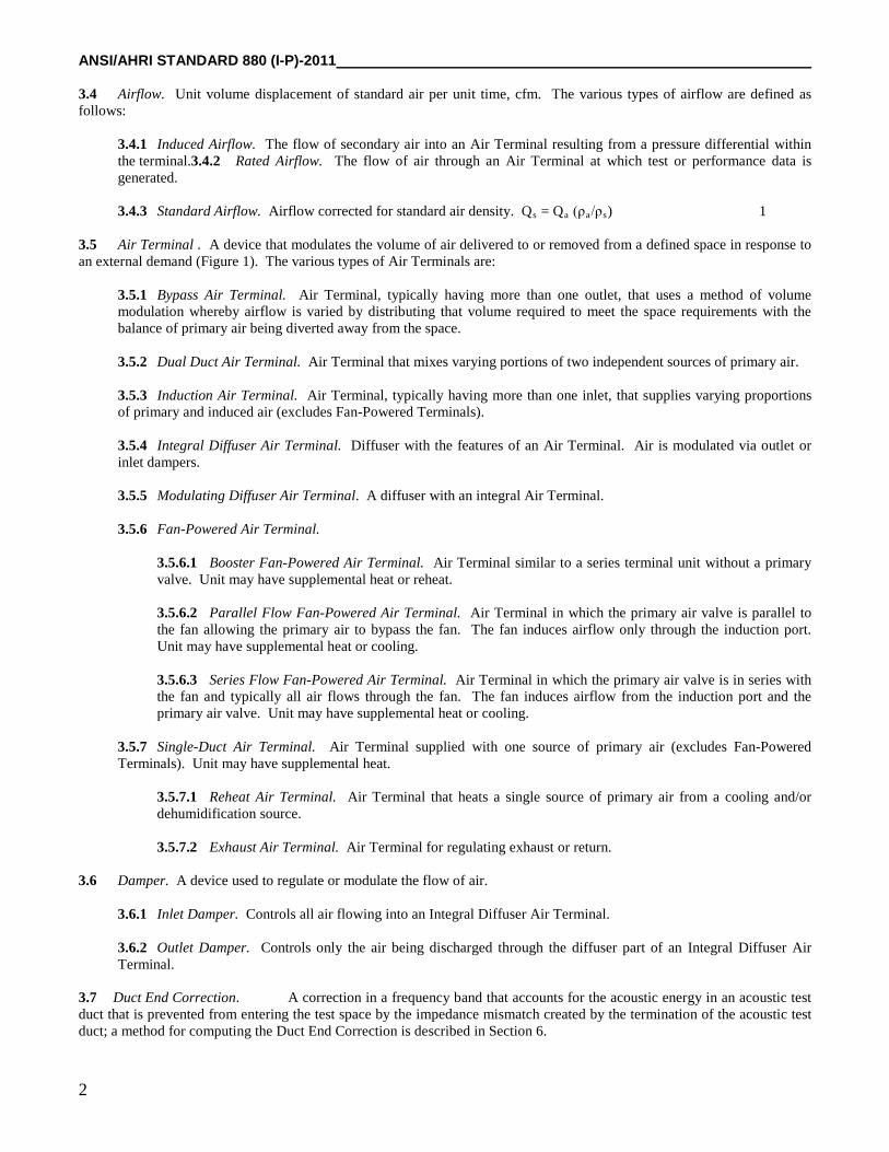
3.4 Airflow. Unit volume displacement of standard air per unit time, cfm. The various types of airflow are defined as follows:
3.4.1 Induced Airflow. The flow of secondary air into an Air Terminal resulting from a pressure differential within the terminal.3.4.2 Rated Airflow. The flow of air through an Air Terminal at which test or performance data is generated.
3.4.3 Standard Airflow. Airflow corrected for standard air density. Qs = Qa (ρa/ρs) 1
3.5 Air Terminal . A device that modulates the volume of air delivered to or removed from a defined space in response to an external demand (Figure 1). The various types of Air Terminals are:
3.5.1 Bypass Air Terminal. Air Terminal, typically having more than one outlet, that uses a method of volume modulation whereby airflow is varied by distributing that volume required to meet the space requirements with the balance of primary air being diverted away from the space.
3.5.2 Dual Duct Air Terminal. Air Terminal that mixes varying portions of two independent sources of primary air. 3.5.3 Induction Air Terminal. Air Terminal, typically having more than one inlet, that supplies varying proportions of primary and induced air (excludes Fan-Powered Terminals). 3.5.4 Integral Diffuser Air Terminal. Diffuser with the features of an Air Terminal. Air is modulated via outlet or inlet dampers.
3.5.5 Modulating Diffuser Air Terminal. A diffuser with an integral Air Terminal. 3.5.6 Fan-Powered Air Terminal.
3.5.6.1 Booster Fan-Powered Air Terminal. Air Terminal similar to a series terminal unit without a primary valve. Unit may have supplemental heat or reheat.
3.5.6.2 Parallel Flow Fan-Powered Air Terminal. Air Terminal in which the primary air valve is parallel to the fan allowing the primary air to bypass the fan. The fan induces airflow only through the induction port. Unit may have supplemental heat or cooling.
3.5.6.3 Series Flow Fan-Powered Air Terminal. Air Terminal in which the primary air valve is in series with the fan and typically all air flows through the fan. The fan induces airflow from the induction port and the primary air valve. Unit may have supplemental heat or cooling.
3.5.7 Single-Duct Air Terminal. Air Terminal supplied with one source of primary air (excludes Fan-Powered Terminals). Unit may have supplemental heat.
3.5.7.1 Reheat Air Terminal. Air Terminal that heats a single source of primary air from a cooling and/or dehumidification source.
3.5.7.2 Exhaust Air Terminal. Air Terminal for regulating exhaust or return.
3.6 Damper. A device used to regulate or modulate the flow of air.
3.6.1 Inlet Damper. Controls all air flowing into an Integral Diffuser Air Terminal.
3.6.2 Outlet Damper. Controls only the air being discharged through the diffuser part of an Integral Diffuser Air Terminal.
3.7 Duct End Correction. A correction in a frequency band that accounts for the acoustic energy in an acoustic test duct that is prevented from entering the test space by the impedance mismatch created by the termination of the acoustic test duct; a method for computing the Duct End Correction is described in Section 6.

ANSI/AHRI STANDARD 880 (I-P)-2011
3
3.8 Equivalent Diameter. Diameter of a circular equivalent of any duct used to determine equal cross-sectional areas. 3.9 Model. An Air Terminal of the same type with similar characteristics available in a progression of sizes. For Fan-Powered Air Terminals, a model is defined by a fan size and a progression of various inlet dimensions. For non-Fan-Powered Air Terminals, it is an Air Terminal of various inlet dimensions. 3.10 Octave Band. A band of sound covering a range of frequencies such that the highest is twice the lowest. The octave band center frequencies of interest are listed in Table 1:
Table 1. Octave Band Center Frequencies Octave Band Center Frequency (Hz)
2 125 3 250 4 500 5 1000 6 2000 7 4000
3.11 Piezometric Ring. A duct static pressure averaging apparatus in which a common tube interconnects at least four evenly spaced duct wall taps and is connected to a pressure measuring device. 3.12 Power Factor. The ratio of real power to apparent power. Power Factor is a way to describe how much of the current contributes to power in the load. A Power Factor of one indicates that 100% of the current is contributing to power in the load. 3.13 Pressure. For the purpose of this standard, pressure shall be associated with standard air.
3.13.1 Minimum Operating Pressure. The static pressure drop through an Air Terminal at a given airflow rate with the damper/valve placed in its full open position by its actuator in its normal operating mode. 3.13.2 Pressure Compensated Control System. Airflow through the Air Terminal is independent of system pressure.
3.13.3 Pressure Dependent Control System. Airflow through the Air Terminal varies in response to system pressure.
3.14 Published Rating. A rating of the assigned values of those performance characteristics, under stated Rating Conditions, by which a unit may be chosen to fit its application. These values apply to all units of like nominal size and type (identification) produced by the same manufacturer. As used herein, the term Published Rating includes the rating of all performance characteristics shown on the unit or published in specifications, advertising or other literature controlled by the manufacturer, at stated Rating Conditions.
3.14.1 Application Rating. A rating based on tests performed at application Rating Conditions (other than Standard Rating Conditions). 3.14.2 Standard Rating. A rating based on tests performed at Standard Rating Conditions. 3.14.3 Certification. A manufacturer participating in an AHRI performance certification program shall use the designation AHRI Performance Certified Ratings.
3.15 Quiet Air Supply. Condition in which the Sound Power Level introduced in the frequency band of interest by the air supply alone is at least 10 dB lower than the measured Sound Power Level generated by the air supply and the Air Terminal under test. 3.16 Rating Conditions. Any set of operating conditions under which a single level of performance results, and which causes only that level of performance to occur.
3.16.1 Standard Rating Conditions. Rating Conditions used as the basis of comparison for performance characteristics.

ANSI/AHRI STANDARD 880 (I-P)-2011
4
3.17 Retrofit Unit. Air Terminal intended for installation into existing air distribution systems, and containing little or no sound attenuating materials.
Figure 1. Air Terminal and Air Outlet Configuration

ANSI/AHRI STANDARD 880 (I-P)-2011
5
3.18 "Shall" or “Should." "Shall" or "should" shall be interpreted as follows:
3.18.1 Shall. Where "shall" or "shall not" is used for a provision, that provision is mandatory if compliance with the standard is claimed.
3.18.2 Should. "Should" is used to indicate provisions which are not mandatory but are desirable as good practice.
3.19 Size. Air Terminal characteristics related to the dimensions of the unit. 3.20 Sound Power. In a specified frequency band, the rate at which sound energy is radiated by a noise source, watts. 3.20.1 Discharge Sound Power. Sound Power transmitted from an air terminal outlet. 3.20.2 Radiated Sound Power. Sound Power transmitted from an air terminal casing (plus induction port for Fan-
Powered Air Terminals). 3.21 Sound Power Level, Lw. Ten times the logarithm to the base ten of the ratio of the Sound Power radiated by the source to a reference Sound Power, expressed in decibels, (dB). The reference Sound Power used in this standard is 1 picowatt (pW). 3.22 Sound Pressure. In a specified frequency band, a fluctuating pressure superimposed on the static pressure by the presence of sound. 3.23 Sound Pressure Level (Lp). Twenty times the logarithm to the base ten of the ratio of the Sound Pressure radiated by the noise source under test to a reference sound pressure of 20 micropascals, dB. 3.24 Terminal Casing Leakage. Amount of air (at standard conditions) escaping from the terminal at a given inlet pressure with only the outlet(s) blocked and with the damper/valve fully opened. 3.25 Terminal Damper Leakage. Amount of air (at standard conditions) passing through a fully closed damper/valve at a given inlet pressure.
Section 4. Symbols 4.1 Symbols. The symbols used throughout this standard are shown in Table 2.
Table 2. Symbols
Symbol
Quantity
Units
A Internal cross section of duct ft2 De Equivalent diameter = 4 A/⋅ π Ft
P Absolute static pressure in. H2O Pa Atmospheric pressure in. Hg Pv Velocity pressure = ρ · (V/1096)2 in. H2O Ps Static pressure in. H2O Pt Total pressure = Pv + Ps in. H2O ΔP Differential pressure in. H2O ΔPt Total differential pressure in. H2O Qa Airflow at actual test conditions ft3/min (cfm) Qs Airflow at standard conditions ft3/min (cfm) V Air Velocity ft/min (fpm)

ANSI/AHRI STANDARD 880 (I-P)-2011
6
Section 5. Classifications 5.1 Classifications. Air Terminal units falling within the scope of this standard shall be classified as one of the following nine types:
5.1.1 Single-Duct Air Terminals (Figure 1.a) 5.1.2 Induction Air Terminals (Figure 1.b) 5.1.3 Bypass Air Terminals (Figure 1.c) 5.1.4 Dual Duct Air Terminals (Figure 1.d) 5.1.5 Integral Diffuser Air Terminals with Inlet Damper (Figure 1.e) 5.1.6 Integral Diffuser Air Terminals with Outlet Damper (Figure 1.f) 5.1.7 Series Flow, Fan-Powered Air Terminals (Figure 1.g) 5.1.8 Parallel Flow, Fan-Powered Air Terminals (Figure 1.h) 5.1.9 Modulating Diffuser Air Terminals (Ceiling-Mounted and Wall-Mounted) (Figure 1.i)
Section 6. Test Requirements 6.1 Test Requirements. Air Terminals shall be tested in accordance with ASHRAE Standard 130, except as noted below.
6.1.1 Calibration. Instruments shall be calibrated at least once per year by comparison with a certified standard in the range of use or shall itself have been certified as to accuracy. 6.1.2 Airflow and Pressure Measurements.
6.1.2.1 Supply Air Static Pressure . The static pressure of the air entering the test unit shall be measured
by means of a Piezometer Ring per Section 4.6.2 of ASHRAE Standard 130.
6.1.2.2 Discharge Air Static Pressure . The static pressure of the air shall be measured at 2.5 duct diameters downstream of the air terminal outlet. A Piezometer Ring shall be used if static pressure traverse measurements are not uniform within 10%.
6.1.2.3 Induced Airflow. Induced airflow is calculated by subtracting the primary airflow from the
discharge (total) airflow. Primary airflow is measured in accordance with Section 4.4 of ASHRAE Standard 130 and discharge (total) airflow is measured in accordance with Section 5.1 of ASHRAE Standard 130.
6.1.2.4 Radiated Sound Power Tests - Series Flow Fan Terminals. The total airflow discharging the test
unit shall be measured using an acoustically isolated flow measuring device installed as shown in Figure 6 of ASHRAE Standard 130 (3.5·De distance to discharge flow measuring device is a minimum value).
6.1.3 Sound Measurements.
6.1.3.1 Sound Power Determination. Sound power levels shall be determined for the Octave bands from 125 to 4000 Hertz according to AHRI Standard 220. AHRI Standard 220 specifies the instrumentation, test facilities, sound power calculation method, required data to be taken, Reference Sound Source (RSS) requirements and reverberation room qualification procedures. Unit setup and configuration shall be according to ASHRAE Standard 130. 6.1.3.2 Reverberation Room Qualification. Units tested and rated in accordance with AHRI Standard 880 (I-P) are required to be tested in a reverberation room that meets the broadband requirements of AHRI Standard
ρa Air density at actual test conditions lbm/ft3 ρs Air density at standard conditions lbm/ft3 Lw Sound Power Level dB Lp Sound Pressure Level dB

ANSI/AHRI STANDARD 880 (I-P)-2011
7
220. Units certified in accordance with the AHRI Standard 880 (I-P) Certification Program are required to be verified by a test in a reverberation room that meets both the broadband and pure tone qualification requirements of AHRI Standard 220. 6.1.3.3 Sound Data Requirements. Sound measurements shall be performed in one-third octave band levels from 100 Hz to 5000 Hz center frequencies. Corrections for background noise and for the computation of the one third octave band sound power levels shall be per AHRI Standard 220. When an end reflection correction (Section 6.1.3.9) is required it shall only be applied to the one third octave band sound power levels. The Octave band Sound Power levels shall be calculated per AHRI Standard 220 from the corrected one third octave band sound power levels. 6.1.3.4 Discharge Sound Power. To determine discharge Sound Power Level, the Air Terminal shall be installed in accordance with Figures 9.1 through 9.3 of ASHRAE Standard 130. The test duct shall be flush with the inside wall of the reverberation room. Alternatively, for Integral Diffuser Air Terminals, the discharge Sound Power Level may be determined in accordance with Figure 9.4 of ASHRAE Standard 130. For Modulating Diffuser Air Terminals, the discharge Sound Power Level shall be determined in accordance with Figures 5 and 6 of ANSI/ASHRAE Standard 70. 6.1.3.5 Radiated Sound Power. The Air Terminal shall be installed in accordance with Figures 10.1 through 10.3 of ASHRAE Standard 130 to determine radiated Sound Power Level.
6.1.3.6 Mounting of Equipment Requiring Support. To achieve isolation, a trapeze type mounting with rubber isolating pads shall be used for all compatible Air Terminals. 6.1.3.7 Dual Duct Air Terminal Test Configuration. Dual Duct Air Terminals shall be tested with one valve controlling airflow and one valve fully closed.
6.1.3.8 Acoustically Isolated Duct. Recommendations for acoustically isolated ducts, or equivalents, used as inlet and outlet ducts in radiated sound tests are shown in Figures 2 and 3.
Figure 2. Acoustically Isolated Duct
SHEET METAL DUCT
2 in. THICK FIBERGLASS
0.04 – 0.06 in. VINYL COVER
2 in. THICK FIBERGLASS
5/8 in. THICK SHEETROCK BANDED IN PLACE

ANSI/AHRI STANDARD 880 (I-P)-2011
8
Figure 3. Acoustically Isolated (Lagged) Duct 6.1.3.9 Ducted Discharge Sound Calculations. For ducted discharge sound installations a duct end correction (E1) shall be added to each one-third octave band sound power level. The addition of the duct end correction (E1) provides the user with the sound power that would be transmitted into an acoustically, non-reflective duct system. The duct end correction shall be calculated using Equation 2.
+
e
o
DfC = E
π 7.01log10
2
1 2
Where: f = One-third octave band center frequency, Hz Co = Speed of sound in air, ft/s De = Equivalent Diameter as defined in section 3.1 of ASHRAE Standard 130, ft E1 = Duct End Correction, dB It should be understood that the duct end corrections become numerically large for products with small equivalent duct diameters. This may tend to overstate the sound power levels at low frequencies for such small products. Therefore, if the value for E1 is greater than 14 dB, set E1 equal to 14 dB.
Section 7. Rating Requirements 7.1 Standard Ratings. Standard Ratings shall be established at the Standard Rating Conditions specified in 7.2. All Standard Ratings shall be verified by tests in accordance with Section 6.
7.1.1 Values of Standard Ratings. Standard Ratings relating to airflow rates shall be expressed only in cfm of Standard Air and stated as follows:
Table 3. Expression of Airflow Rates Range,
cfm [m3/s] Rate to Nearest, cfm
0 to 49 1 50 to 199 5
200 to 999 10
1000 and over 25
Discharge and radiated Sound Power Level shall be expressed to the nearest 1 dB. Levels lower than values shown in Table 4 shall be listed as being insignificant. The Sound Power Level shall be determined for the octave band center frequencies from 125 to 4000 Hz. Fan power shall be expressed to the nearest watt. Optional units of watts/cfm shall be expressed to the nearest watt/cfm. Terminal casing and damper leakages shall be expressed to the nearest cfm. Static pressure shall be expressed to the nearest 0.01 in. H2O.
Table 4. Minimum Significant Sound Power Levels Octave Band Center Frequency, Hz
125
250
500
1000
2000
4000
Sound Power Level, dB
36
29
26
22
19
17
ANSI/AHRI STANDARD 880 (I-P)-2011
9
7.2 Standard Rating Conditions.
7.2.1 Airflow Rate and Minimum Operating Pressure.
7.2.1.1 Primary Air Damper. The standard rated airflow and Minimum Operating Pressure shall be established and published in accordance with Tables 5 and 6.
7.2.1.2 Integral Fan. The fan airflow rating shall be established and published at 0.25 in. H2O discharge static pressure or minimum recommended pressure (whichever is greater) with any fan volume Dampers at wide open position, and primary air Damper closed.
7.2.1.3 Induction Terminal. The induced airflow shall be rated and published using 0.25 in. H2O discharge (downstream) static pressure with the primary air Damper set to achieve 25% of the standard rated airflow and 1.5 in. H2O inlet static pressure. The induction Damper(s) shall be set in the full open position.
7.2.2 Sound Power Rating. The Sound Power Level, dB, for both Discharge and Radiated Sound Power shall be established and published at the Standard Rating Conditions (Table 6). 7.2.3 Terminal Casing and Damper Leakage. 7.2.3.1 Casing and Damper Leakage for Single Duct Air Terminal Units. The casing leakage on
single duct air terminal units shall be established and published at the standard rating conditions of ½ inch static pressure. Damper leakage shall be established and published at 1 inch inlet static pressure.
7.2.3.2 Casing and Damper Leakage for Dual Duct Air Terminal Units. The casing leakage on
dual duct air terminal units shall be established at the standard rating conditions of 1 inch static pressure. Damper leakage shall be established and published at 6 inch inlet static pressure.
7.3 Application Ratings. Data at conditions other than those specified in Section 7.2 may be published as Application Ratings and shall be determined in accordance with the method of testing described in Section 6. 7.4 Appurtenance Ratings. The air terminal data referred to in Section 7.2 represent the performance of the base Air Terminal without appurtenances.

ANSI/AHRI STANDARD 880 (I-P)-2011
10
Table 5. Recommended Inlet Airflow Inlet Duct Diameter, Inch Airflow, cfm
4 150 5 250 6 400 7 550 8 700 9 900
10 1100 12 1600 14 2100 16 2800 18 3500 20 4400 22 5300 24 6300
NOTES: 1. Any other size unit or configuration shall be rated at the airflow rate calculated from multiplying the nominal inlet area, ft2 by 2000
fpm air velocity. 2 For Series Flow Fan-Powered Air Terminals, the rated airflow cfm for the primary air Damper shall be the lower of the fan rating flow
or the rated airflow according to the above table. 3. Integral Diffuser Air Terminals and Bypass Air Terminals shall be rated at the manufacturer's recommended airflow. 4. Modulating Diffuser Air Terminals shall be rated at 750 fpm and 400 fpm neck velocity.
Table 6. Discharge/Radiated Sound Power Level Standard Rating Conditions
Terminal Type Test Point
Type of Sound Fan 2 Primary Air Radiated Discharge Discharge (Downstream)
Static Pressure in. H2O1 Airflow Percent of
Rated Airflow Differential Static Pressure in. H2O
Single Duct, Dual Duct, Integral Diffuser Air Terminals
1 2
Yes ─
─ Yes
NA NA
NA NA
100 100
1.5 1.5
Modulating Diffuser Air Terminals
1 2
- -
Yes Yes
NA NA
NA NA
1006
Throttled7 Minimum See Note 7
Bypass Air Terminals 1 2
Yes -
- Yes
NA NA
NA NA
100 100
Minimum Minimum
Parallel Flow, Fan-Powered Air Terminals & Induction Air Terminals Fan Only 1
2 Yes ─
─ Yes
0.25 0.25
On On
Off Off
─ ─
Primary Air Only
3 4
Yes ─
─
Yes
0.25 0.25
Off 5 Off 5
100 100
1.5 1.5
Series Flow, Fan-Powered Air Terminals Fan Only 1 ─ Yes 0.25 On Off _
Fan and Primary Air
2 3
Yes Yes
─ ─
0.25 0.25
On On
Off
100 3
-
1.54 NOTES: 1. All fan tests for Radiated and Discharge Sound Power in Fan-Powered Air Terminals shall be run at 0.25 in. H2O discharge static
pressure or at minimum recommended discharge static pressure, whichever is higher. 2. Fan to be adjusted to its rated airflow, using manufacturer's recommended procedure. 3. Primary airflow set for 100% recommended inlet airflow in accordance with Table 5 or fan maximum rated airflow, whichever is lower. 4. Inlet static pressure referenced to atmosphere for Series Flow Fan-Powered Air Terminal only. 5. Induction Terminals shall be tested with induction Dampers set fully closed. 6. At full open damper position and 750 fpm neck velocity. 7. At the throttled damper position which produces the manufacturer’s maximum recommended inlet static pressure at 400 fpm neck
velocity.

ANSI/AHRI STANDARD 880 (I-P)-2011
11
7.5 Publication of Ratings. Wherever application ratings are published or printed, they shall include or be accompanied by the Standard Rating, clearly designated as such, including a statement of the conditions at which the ratings apply. 7.6 Tolerances. To comply with this standard, published ratings shall be based on data obtained in accordance with the provisions of Sections 5 and 6 of this standard, and shall be such that any production Air Terminal, when tested, will meet these ratings within the following tolerances:
7.6.1 Airflow shall be greater than or equal to 95% of the rating at the published Minimum Operating Pressure.
7.6.2 For Fan-Powered Air Terminals, airflow shall be greater than or equal to 95% of the rating at the published Minimum Operating Pressure, the electrical power input shall not be more than 110% of the rated value, and the optional energy consumption shall not be more than the rated value. For Induction Air Terminals, the induced airflow shall be greater than or equal to 95% of the rating. 7.6.3 Sound Power Levels shall not exceed the published values in each Octave Band by more than the rating tolerance shown below:
Table 7. Sound Power Level Rating Tolerances
Octave Band Center Frequencies, Hz
Rating Tolerance dB
125 6 250 4 500 3
1000 3 2000 3 4000 3
7.6.4 Terminal Casing and Damper Leakages shall not exceed the published values by 5% or 1 cfm, whichever is greater.
Section 8. Minimum Data Requirements for Published Ratings 8.1 Minimum Data Requirements for Published Ratings. Published ratings shall include Standard Ratings and may also include Application Ratings. The following information shall be published for all Standard Ratings.
8.1.1 A listing of all applicable rating conditions specified 8.1.2 Primary airflow rate, cfm 8.1.3 Induced or fan airflow rate, cfm 8.1.4 Minimum operating pressure, in. H2O 8.1.5 Octave Band Sound Power Level, dB (125 to 4000 Hz) (Radiated and/or Discharge with Duct End
Correction) 8.1.6 Electrical power input at fan rating point, watts (Fan-Powered Air Terminals only) 8.1.7 Terminal Casing Leakage, cfm 8.1.8 Terminal Damper Leakage, cfm
8.2 Optional Published Ratings for Energy Consumption of Fan-Powered Air Terminals. 8.2.1 Energy Consumption Rating Provisions for Series Flow Fan-Powered Terminals.
For Series Flow Fan-Powered Terminals, using a given fan size and motor combination, map the fan only energy consumption at 0.25 in. H2O external static pressure at four operating points: Fan maximum, 75% fan range, 50% fan range and 25% fan range.At each point, report (publish):
8.2.1.1 Energy consumption rating, watts/cfm

ANSI/AHRI STANDARD 880 (I-P)-2011
12
8.2.1.2 Fan power, watts 8.2.1.3 Airflow, cfm 8.2.1.4 Voltage, V 8.2.1.5 Frequency, Hz 8.2.1.6 Motor designation 8.2.1.7 Power Factor 8.2.1.8 Motor nameplate power, HP
8.2.2 Energy Consumption Rating Provisions for Parallel Flow Fan-Powered Terminals.
For Parallel Flow Fan-Powered Terminals, using a given fan size and motor combination, map the fan only energy consumption at 0.25 in. H2O external static pressure at four operating points: 80% fan range, 60% fan range, 40% fan range and 20% fan range. At each point, report (publish):
8.2.2.1 Energy consumption rating, watts/cfm 8.2.2.2 Fan power, watts 8.2.2.3 Airflow, cfm 8.2.2.4 Voltage, V 8.2.2.5 Frequency, Hz 8.2.2.6 Motor designation 8.2.2.7 Power Factor 8.2.2.8 Motor nameplate power, HP
Section 9. Marking
9.1 Model Identification. The label on each Air Terminal shall include sufficient model and size identification to correlate with published data, literature and any other advertising issued by the manufacturer.
Section 10. Voluntary Conformance 10.1 Conformance. While conformance with this standard is voluntary, conformance shall not be claimed or implied for products or equipment within the standard’s Purpose (Section 1) and Scope (Section 2) unless such product claims meet all the requirements of the standard and all of the testing and rating requirements are measured and reported in complete compliance with the standard. Any product that has not met all the requirements of the standard cannot reference, state, or acknowledge the standard in any written, oral, or electronic communication.

ANSI/AHRI STANDARD 880 (I-P)-2011
13
APPENDIX A. REFERENCES – NORMATIVE A1 Listed here are all standards, handbooks, and other publications essential to the formation and implementation of the standard. All references in this appendix are considered as part of this standard.
A1.1 AHRI Standard 220-2007, Reverberation Room Qualification and Testing Procedures for Determining Sound Power of HVAC Equipment, 2007, Air-Conditioning, Heating, and Refrigeration Institute, 2111 Wilson Boulevard, Suite 500, Arlington, VA 22201, U.S.A.
A1.2 AHRI Standard 410-2001, Forced Circulation Air-Cooling and Air-Heating Coils, 2001, Air-Conditioning, Heating, and Refrigeration Institute, 2111 Wilson Blvd., Suite 500, Arlington, VA 22201, U.S.A.
A1.3 AHRI Standard 440-2008, Performance Rating of Room Fan-Coils, 2008, Air-Conditioning, Heating, and Refrigeration Institute, 2111 Wilson Blvd., Suite 500, Arlington, VA 22201, U.S.A. A1.4 AHRI Standard 885-2008 (with Addendum 1 dated March 2011) , Procedure for Estimating Occupied Space Sound Levels in the Application of Air Terminals and Air Outlets, 2008, Air-Conditioning, Heating, and Refrigeration Institute, 2111 Wilson Blvd., Suite 500, Arlington, VA 22201, U.S.A.
A1.5 ANSI/ASHRAE 70-2006 (R2011), Method of Testing for Rating the Performance of Air Outlets and Inlets, 2006, American Society of Heating, Refrigerating, and Air-Conditioning Engineers, Inc., 1791 Tullie Circle N.E., Atlanta, GA 30329, U.S.A.
A1.6 ASHRAE 130-2008, Methods of Testing for Rating Ducted Air Terminal Units, 2008, American Society of Heating, Refrigerating, and Air-Conditioning Engineers, Inc., 1791 Tullie Circle N.E., Atlanta, GA 30329, U.S.A.
A1.7 ASHRAE Terminology of Heating, Ventilation, Air Conditioning, & Refrigeration, 1991, Second Edition, American Society of Heating, Refrigerating, and Air-Conditioning Engineers, Inc., 1791 Tullie Circle N.E., Atlanta, GA 30329, U.S.A.
APPENDIX B. REFERENCES – INFORMATIVE
B1.1 RP-1314, TRNS-00315-2007, ASHRAE Transactions, Salt Lake City, UT, USA, June 2008, Experimental
Investigation of Reflection of Airborne Noise at Duct Terminations, Alexander P. Michaud and Kenneth A. Cunefare, PhD., American Society of Heating, Refrigerating, and Air-Conditioning Engineers, Inc., 1791 Tullie Circle N.E., Atlanta, GA 30329, U.S.A.