2011 Maryland Standards and Specifications for Soil Erosion and
292
2 2 2 0 0 0 1 1 1 1 1 1 M M M a a a r r r y y y l l l a a a n n n d d d S S S t t t a a a n n n d d d a a a r r r d d d s s s a a a n n n d d d S S S p p p e e e c c c i i i f f f i i i c c c a a a t t t i i i o o o n n n s s s f f f o o o r r r S S S o o o i i i l l l E E E r r r o o o s s s i i i o o o n n n a a a n n n d d d S S S e e e d d d i i i m m m e e e n n n t t t C C C o o o n n n t t t r r r o o o l l l December 2011 Maryland Department of the Environment Water Management Administration in association with Natural Resources Conservation Service and Maryland Association of Soil Conservation Districts
Transcript of 2011 Maryland Standards and Specifications for Soil Erosion and
222000111111 MMMaaarrryyylllaaannnddd
SSStttaaannndddaaarrrdddsss aaannnddd SSSpppeeeccciiifffiiicccaaatttiiiooonnnsss
fffooorrr SSSoooiiilll EEErrrooosssiiiooonnn aaannnddd SSSeeedddiiimmmeeennnttt
CCCooonnntttrrrooolll
December 2011
Maryland Department of the Environment
Water Management Administration
in association with
Natural Resources Conservation Service
and
Maryland Association of Soil Conservation Districts


This book is dedicated to the memory of our colleague and friend Richard Trickett (1955-2012) who will be remembered for his remarkable knowledge and tireless quest to improve sediment control in the State of Maryland.


i
ACKNOWLEDGEMENTS
The latest revisions to the Maryland Standards and Specifications for Soil Erosion and Sediment Control are a
result of the effort of a Technical Workgroup that consists of members from the Maryland Soil Conservation
Districts (MASCD), Natural Resources Conservation Service (NRCS), local Maryland governments, Maryland
State Highway Administration (SHA), Maryland Environmental Services (MES), Maryland Department of the
Environment (MDE), as well as everyone who submitted comments and suggestions. MDE secured the
consulting services of Whitney Bailey Cox and Magnani, LLC (WBCM) and Michael Baker Engineering through
MES to assist in the development of the draft document.
Many individuals assisted with the revision to this document by providing review comments, suggestions,
sketches, drawings, and reference documents. We would like to acknowledge the following individuals for their
invaluable contributions:
Allan Stahl (Natural Resources Conservation Service)
Jeff West (Baltimore County SCD)
Bryan Snyder (Carroll County SCD)
Fred Jones (Carroll County)
Chris Brown (Cecil County SCD)
Van Funk (Cecil County)
Bill Tharpe (Harford County)
Geof Schoming (Howard County SCD)
David Bourdon (Prince George’s County SCD)
James Whisonant (Prince George’s County SCD)
Lance Gardner (Prince George’s County SCD)
David Kuykendall (Montgomery County)
Rick Brush (Montgomery County)
Bruce Young (St. Mary’s County SCD)
Michael Wagner (Loiederman Soltesz Associates)
Craig Zinter (Talbot County SCD)
Dee Price (Washington County SCD)
Karuna Pujara (SHA)
Steve Buckley (SHA)
Dan Sajedi (SHA)
Austin Eckert (MDE)
Oluseun Omotoso (MDE)
Michael Gebreyesus (MDE)
Solomon Adamu (MDE)
James Tracy (MDE)
Amanda Malcolm (MDE)
Richard Trickett (MDE)
Maria Warburton (MDE)
Ken Pensyl (MDE)
The consultant project team members included the following individuals:
Brian Noll, Project Manager (WBCM)
James Kramperth (WBCM)
Jason Reinhardt (WBCM)
Mike Moore (WBCM)
Phil Carroll (WBCM)
Dennis Santeufemio (WBCM)
Melisa Keimig (WBCM)
Charlene Osborne (WBCM)
Saada Russell (WBCM)
Patty Kulishek (WBCM)
Tristram Madden (Michael Baker)
Vic Siaurusaitus (Michael Baker)
Kate Meade (MES)
Kerri Martin (MES)
Michael Herzberger (MES)
ii
SUMMARY
The “2011 Maryland Standards and Specifications for Soil Erosion and Sediment Control” provides
guidance for applicants, designers, plan reviewers, developers, contractors, and inspectors to control sediment-
laden runoff from construction sites and ensure the protection of Maryland’s streams, rivers, and the Atlantic
Coastal and Chesapeake Bays.
The document consists of an introduction, a planning and design section, and seven sections of erosion and
sediment control practices. Planning is an important element for today’s site design measures, especially for
meeting “Environmental Site Design (ESD) to the maximum extent practicable (MEP).” A brief description of
each section is outlined below:
Introduction This section describes the purpose of the manual, impacts of sedimentation, and factors that
influence soil erosion.
Section A Planning and Design
This section includes the design and review process as it relates to ESD. It outlines design
principles that should be applied throughout the process from planning through design, review,
and inspection. A design methodology is presented with tools for selecting practices under
certain conditions. An erosion and sediment control table (Table A-4) is provided as a quick
reference summarizing the practices, their primary purpose, design criteria, and associated
practices.
Section B Grading and Stabilization
This section describes grading and stabilization requirements to minimize potential for erosion
during construction. Proper utilization of these practices controls erosion at the source and
assists in complying with ESD requirements.
Section C Water Conveyance
Practices in this section are primarily used to convey water around the active construction area
(clear-water diversions) or to a sediment control practice. The conveyance practices can be
used to divide drainage areas into manageable segments. The practice is selected based on
design criteria such as conveying clear-water versus sediment-laden water, slope, and drainage
area.
Section D Erosion Control
This section uses structural practices to reduce erosion from concentrated flow. Erosion control
practices can be used for inflow or outlet protection, velocity checks in swales, or to convey
water down a slope in non-erosive manner. The design of these practices is based on drainage
area, flow rate, location, slope, and velocity.
Section E Filtering
This section describes practices that filter and trap sediment for relatively small drainage areas.
Many of these practices are used in sheet flow conditions and work with ESD principles.
These are designed based on slope length and steepness of the upslope area. Other filtering
practices trap and filter water in concentrated flow conditions.
iii
Section F Dewatering
Dewatering practices are used to remove the water from areas such as foundations for buildings
and bridges, utilities, and sediment traps and basins while filtering sediment. Critical elements
for dewatering practices are the location and clarity of the discharge.
Section G Sediment Trapping
Sediment trapping practices are used to detain and settle sediment-laden runoff from larger
drainage areas and include sediment traps and sediment basins. Sediment traps can be used for
drainage areas up to 10 acres. A sediment basin that is to remain as a permanent structure
requires an engineering design in accordance with Natural Resource Conservation Service
(NRCS) Maryland Conservation Practice Standard Code No. 378 for Ponds. Also included are
associated practices used with the design and construction of sediment traps and basins.
Section H Miscellaneous
This section includes specifications for materials, subsurface drains, channels, temporary
access waterway crossings, dust control, and onsite concrete washout structures.
Bibliography A list is provided of the reference material used to support the development and improvements
to the Standards and Specifications.
Glossary Definitions of commonly used terms can be found in the Glossary.

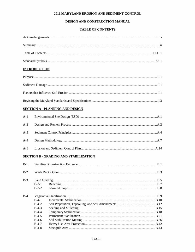
2011 MARYLAND EROSION AND SEDIMENT CONTROL
DESIGN AND CONSTRUCTION MANUAL
TABLE OF CONTENTS
TOC.1
Acknowledgements ........................................................................................................................................... i
Summary .......................................................................................................................................................... ii
Table of Contents ....................................................................................................................................TOC.1
Standard Symbols ...................................................................................................................................... SS.1
INTRODUCTION
Purpose ...........................................................................................................................................................I.1
Sediment Damage ..........................................................................................................................................I.1
Factors that Influence Soil Erosion ...............................................................................................................I.1
Revising the Maryland Standards and Specifications ..................................................................................I.3
SECTION A - PLANNING AND DESIGN
A-1 Environmental Site Design (ESD) ................................................................................................ A.1
A-2 Design and Review Process .......................................................................................................... A.2
A-3 Sediment Control Principles. ......................................................................................................... A.4
A-4 Design Methodology ..................................................................................................................... A.7
A-5 Erosion and Sediment Control Plan ............................................................................................ A.14
SECTION B - GRADING AND STABILIZATION
B-1 Stabilized Construction Entrance .................................................................................................. B.1
B-2 Wash Rack Option ......................................................................................................................... B.3
B-3 Land Grading ................................................................................................................................. B.5
B-3-1 Benching ...................................................................................................................... B.7
B-3-2 Serrated Slope .............................................................................................................. B.8
B-4 Vegetative Stabilization ................................................................................................................. B.9
B-4-1 Incremental Stabilization ........................................................................................... B.10
B-4-2 Soil Preparation, Topsoiling, and Soil Amendments ................................................ B.12
B-4-3 Seeding and Mulching ............................................................................................... B.15
B-4-4 Temporary Stabilization ............................................................................................ B.18
B-4-5 Permanent Stabilization ............................................................................................. B.21
B-4-6 Soil Stabilization Matting .......................................................................................... B.36
B-4-7 Heavy Use Area Protection ....................................................................................... B.42
B-4-8 Stockpile Area ........................................................................................................... B.43
TOC.2
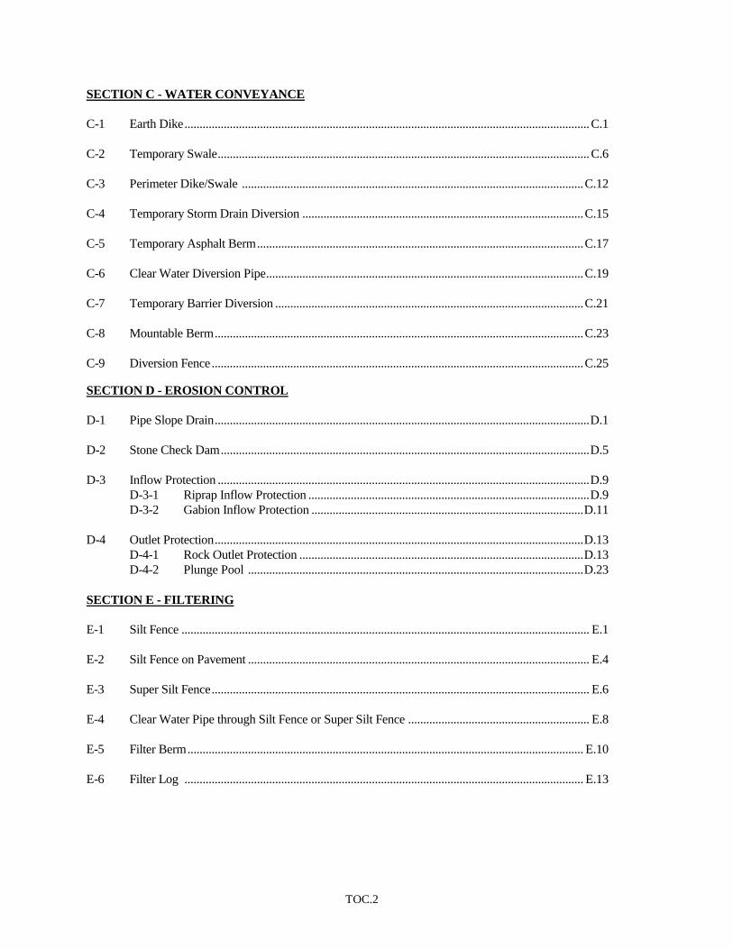
SECTION C - WATER CONVEYANCE
C-1 Earth Dike ...................................................................................................................................... C.1
C-2 Temporary Swale ........................................................................................................................... C.6
C-3 Perimeter Dike/Swale ................................................................................................................. C.12
C-4 Temporary Storm Drain Diversion ............................................................................................. C.15
C-5 Temporary Asphalt Berm ............................................................................................................ C.17
C-6 Clear Water Diversion Pipe ......................................................................................................... C.19
C-7 Temporary Barrier Diversion ...................................................................................................... C.21
C-8 Mountable Berm .......................................................................................................................... C.23
C-9 Diversion Fence ........................................................................................................................... C.25
SECTION D - EROSION CONTROL
D-1 Pipe Slope Drain ............................................................................................................................ D.1
D-2 Stone Check Dam .......................................................................................................................... D.5
D-3 Inflow Protection ........................................................................................................................... D.9
D-3-1 Riprap Inflow Protection ............................................................................................. D.9
D-3-2 Gabion Inflow Protection .......................................................................................... D.11
D-4 Outlet Protection .......................................................................................................................... D.13
D-4-1 Rock Outlet Protection .............................................................................................. D.13
D-4-2 Plunge Pool ............................................................................................................... D.23
SECTION E - FILTERING
E-1 Silt Fence ....................................................................................................................................... E.1
E-2 Silt Fence on Pavement ................................................................................................................. E.4
E-3 Super Silt Fence ............................................................................................................................. E.6
E-4 Clear Water Pipe through Silt Fence or Super Silt Fence ............................................................ E.8
E-5 Filter Berm ................................................................................................................................... E.10
E-6 Filter Log .................................................................................................................................... E.13

TOC.3
E-7 Temporary Stone Outlet Structure .............................................................................................. E.17
E-8 Temporary Gabion Outlet Structure ........................................................................................... E.20
E-9 Storm Drain Inlet Protection ....................................................................................................... E.23
E-9-1 Standard Inlet Protection ........................................................................................... E.24
E-9-2 At-Grade Inlet Protection .......................................................................................... E.26
E-9-3 Curb Inlet Protection ................................................................................................. E.27
E-9-4 Median Inlet Protection ............................................................................................. E.28
E-9-5 Median Sump Inlet Protection ................................................................................... E.29
E-9-6 Combination Inlet Protection..................................................................................... E.30
E-9-7 Gabion Inlet Protection .............................................................................................. E.32
SECTION F - DEWATERING
Dewatering Strategy...................................................................................................................................... F.1
F-1 Removable Pumping Station .......................................................................................................... F.2
F-2 Sump Pit .......................................................................................................................................... F.4
F-3 Portable Sediment Tank ................................................................................................................. F.6
F-4 Filter Bag ........................................................................................................................................ F.8
SECTION G - SEDIMENT TRAPPING
G-1 Sediment Traps .............................................................................................................................. G.1
G-1-1 Pipe Outlet Sediment Trap ST-I .................................................................................. G.4
G-1-2 Stone/Riprap Outlet Sediment Trap ST-II .................................................................. G.9
G-1-3 Riprap Outlet Sediment Trap ST-III .......................................................................... G.14
G-2 Sediment Basins .......................................................................................................................... G.19
G-2-1 Typical Anti-Seep Collars .......................................................................................... G.42
G-2-2 Corrugated Riser Base ............................................................................................... G.43
G-2-3 Concentric Trash Rack and Anti-Vortex Device ...................................................... G.44
G-2-4 Baffle Boards ............................................................................................................. G.46
G-2-5 Types of Couplers for Corrugated Steel Pipe ........................................................... G.47
G-2-6 Sediment Basin Schematic Horizontal Draw Down Device .................................... G.48
G-2-7 Sediment Basin Schematic Vertical Draw Down Device ......................................... G.49
G-2-8 Precast Riser Connector ............................................................................................ G.50
G-2-9 Projection Collar ........................................................................................................ G.51
SECTION H - MISCELLANEOUS
H-1 Materials ........................................................................................................................................ H.1
H-2 Subsurface Drains .......................................................................................................................... H.4
H-3 Channel ........................................................................................................................................ H.10
H-4 Temporary Access Waterways Crossings ................................................................................... H.14

TOC.4
H-4-1 Temporary Access Bridge ......................................................................................... H.16
H-4-2 Temporary Access Culvert ........................................................................................ H.19
H-5 Dust Control................................................................................................................................. H.22
H-6 Onsite Concrete Washout Structure ........................................................................................... H.23
BIBLIOGRAPHY .................................................................................................................................... BB.1
GLOSSARY ............................................................................................................................................. GL.1
TOC.5
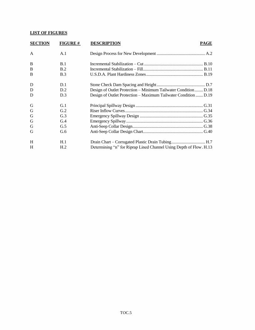
LIST OF FIGURES
SECTION FIGURE # DESCRIPTION PAGE
A A.1 Design Process for New Development .............................................. A.2
B B.1 Incremental Stabilization – Cut ........................................................ B.10
B B.2 Incremental Stabilization – Fill ......................................................... B.11
B B.3 U.S.D.A. Plant Hardiness Zones ...................................................... B.19
D D.1 Stone Check Dam Spacing and Height .............................................. D.7
D D.2 Design of Outlet Protection – Minimum Tailwater Condition ........ D.18
D D.3 Design of Outlet Protection – Maximum Tailwater Condition ....... D.19
G G.1 Principal Spillway Design ................................................................ G.31
G G.2 Riser Inflow Curves .......................................................................... G.34
G G.3 Emergency Spillway Design ............................................................ G.35
G G.4 Emergency Spillway ......................................................................... G.36
G G.5 Anti-Seep Collar Design ................................................................... G.38
G G.6 Anti-Seep Collar Design Chart ......................................................... G.40
H H.1 Drain Chart – Corrugated Plastic Drain Tubing ................................ H.7
H H.2 Determining “n” for Riprap Lined Channel Using Depth of Flow . H.13
TOC.6
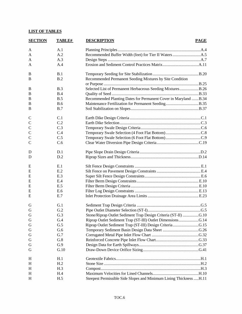
LIST OF TABLES SECTION TABLE# DESCRIPTION PAGE A A.1 Planning Principles ...................................................................................A.4 A A.2 Recommended Buffer Width (feet) for Tier II Waters ............................A.5 A A.3 Design Steps .............................................................................................A.7 A A.4 Erosion and Sediment Control Practices Matrix....................................A.11 B B.1 Temporary Seeding for Site Stabilization ..............................................B.20 B B.2 Recommended Permanent Seeding Mixtures by Site Condition
or Purpose ...............................................................................................B.25 B B.3 Selected List of Permanent Herbaceous Seeding Mixtures...................B.26 B B.4 Quality of Seed .......................................................................................B.33 B B.5 Recommended Planting Dates for Permanent Cover in Maryland .......B.34 B B.6 Maintenance Fertilization for Permanent Seeding.................................B.35 B B.7 Soil Stabilization on Slopes....................................................................B.37 C C.1 Earth Dike Design Criteria .......................................................................C.1 C C.2 Earth Dike Selection.................................................................................C.3 C C.3 Temporary Swale Design Criteria............................................................C.6 C C.4 Temporary Swale Selection (4 Foot Flat Bottom)...................................C.8 C C.5 Temporary Swale Selection (6 Foot Flat Bottom)...................................C.9 C C.6 Clear Water Diversion Pipe Design Criteria..........................................C.19 D D.1 Pipe Slope Drain Design Criteria .............................................................D.2 D D.2 Riprap Sizes and Thickness....................................................................D.14 E E.1 Silt Fence Design Constraints .................................................................. E.1 E E.2 Silt Fence on Pavement Design Constraints ............................................ E.4 E E.3 Super Silt Fence Design Constraints........................................................ E.6 E E.4 Filter Berm Design Constraints..............................................................E.10 E E.5 Filter Berm Design Criteria ....................................................................E.10 E E.6 Filter Log Design Constraints ................................................................E.13 E E.7 Inlet Protection Drainage Area Limits ...................................................E.23 G G.1 Sediment Trap Design Criteria ................................................................G.5 G G.2 Pipe Outlet Diameter Selection (ST-I).....................................................G.5 G G.3 Stone/Riprap Outlet Sediment Trap Design Criteria (ST-II) ................G.10 G G.4 Riprap Outlet Sediment Trap (ST-III) Outlet Dimensions....................G.14 G G.5 Riprap Outlet Sediment Trap (ST-III) Design Criteria..........................G.15 G G.6 Temporary Sediment Basin Design Data Sheet ....................................G.26 G G.7 Corrugated Metal Pipe Inlet Flow Chart ...............................................G.32 G G.8 Reinforced Concrete Pipe Inlet Flow Chart...........................................G.33 G G.9 Design Data for Earth Spillways............................................................G.37 G G.10 Draw-Down Device Orifice Sizing........................................................G.41 H H.1 Geotextile Fabrics.....................................................................................H.1 H H.2 Stone Size .................................................................................................H.2 H H.3 Compost....................................................................................................H.3 H H.4 Maximum Velocities for Lined Channels..............................................H.10 H H.5 Steepest Permissible Side Slopes and Minimum Lining Thickness .....H.11
TOC.7
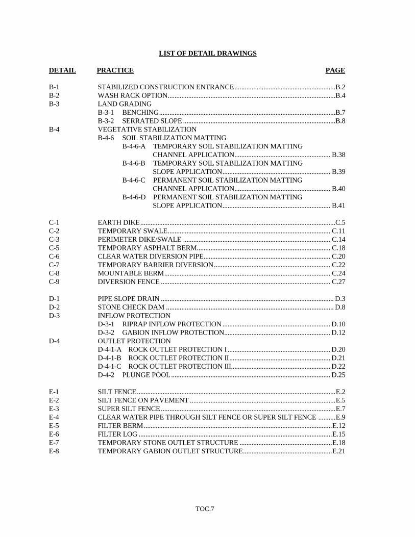
LIST OF DETAIL DRAWINGS
DETAIL PRACTICE PAGE
B-1 STABILIZED CONSTRUCTION ENTRANCE ...........................................................B.2
B-2 WASH RACK OPTION ..................................................................................................B.4
B-3 LAND GRADING
B-3-1 BENCHING .......................................................................................................B.7
B-3-2 SERRATED SLOPE .........................................................................................B.8
B-4 VEGETATIVE STABILIZATION
B-4-6 SOIL STABILIZATION MATTING
B-4-6-A TEMPORARY SOIL STABILIZATION MATTING
CHANNEL APPLICATION ........................................................ B.38
B-4-6-B TEMPORARY SOIL STABILIZATION MATTING
SLOPE APPLICATION ............................................................... B.39
B-4-6-C PERMANENT SOIL STABILIZATION MATTING
CHANNEL APPLICATION ........................................................ B.40
B-4-6-D PERMANENT SOIL STABILIZATION MATTING
SLOPE APPLICATION ............................................................... B.41
C-1 EARTH DIKE ..................................................................................................................C.5
C-2 TEMPORARY SWALE ............................................................................................... C.11
C-3 PERIMETER DIKE/SWALE ...................................................................................... C.14
C-5 TEMPORARY ASPHALT BERM.............................................................................. C.18
C-6 CLEAR WATER DIVERSION PIPE .......................................................................... C.20
C-7 TEMPORARY BARRIER DIVERSION .................................................................... C.22
C-8 MOUNTABLE BERM ................................................................................................. C.24
C-9 DIVERSION FENCE ................................................................................................... C.27
D-1 PIPE SLOPE DRAIN ..................................................................................................... D.3
D-2 STONE CHECK DAM .................................................................................................. D.8
D-3 INFLOW PROTECTION
D-3-1 RIPRAP INFLOW PROTECTION ............................................................... D.10
D-3-2 GABION INFLOW PROTECTION.............................................................. D.12
D-4 OUTLET PROTECTION
D-4-1-A ROCK OUTLET PROTECTION I ............................................................ D.20
D-4-1-B ROCK OUTLET PROTECTION II ........................................................... D.21
D-4-1-C ROCK OUTLET PROTECTION III.......................................................... D.22
D-4-2 PLUNGE POOL ............................................................................................. D.25
E-1 SILT FENCE .................................................................................................................... E.2
E-2 SILT FENCE ON PAVEMENT ..................................................................................... E.5
E-3 SUPER SILT FENCE ...................................................................................................... E.7
E-4 CLEAR WATER PIPE THROUGH SILT FENCE OR SUPER SILT FENCE .......... E.9
E-5 FILTER BERM .............................................................................................................. E.12
E-6 FILTER LOG ................................................................................................................. E.15
E-7 TEMPORARY STONE OUTLET STRUCTURE ...................................................... E.18
E-8 TEMPORARY GABION OUTLET STRUCTURE .................................................... E.21

TOC.8
E-9 STORM DRAIN INLET PROTECTION
E-9-1 STANDARD INLET PROTECTION ........................................................... E.24
E-9-2 AT-GRADE INLET PROTECTION............................................................. E.26
E-9-3 CURB INLET PROTECTION ...................................................................... E.27
E-9-4 MEDIAN INLET PROTECTION ................................................................. E.28
E-9-5 MEDIAN SUMP INLET PROTECTION ..................................................... E.29
E-9-6 COMBINATION INLET PROTECTION .................................................... E.30
E-9-7 GABION INLET PROTECTION .................................................................. E.32
F-1 REMOVABLE PUMPING STATION .......................................................................... F.3
F-2 SUMP PIT ........................................................................................................................ F.5
F-3 PORTABLE SEDIMENT TANK ................................................................................... F.7
F-4 FILTER BAG ................................................................................................................... F.9
G-1 SEDIMENT TRAPS
G-1-1 PIPE OUTLET SEDIMENT TRAP ST-I ........................................................ G.6
G-1-2 STONE/RIPRAP OUTLET SEDIMENT TRAP ST-II ................................ G.11
G-1-3 RIPRAP OUTLET SEDIMENT TRAP ST-III ............................................. G.16
G-2 SEDIMENT BASINS
G-2-1 TYPICAL ANTI-SEEP COLLARS .............................................................. G.42
G-2-2 CORRUGATED RISER BASE ..................................................................... G.43
G-2-3 CONCENTRIC TRASH RACK AND ANTI-VORTEX DEVICE ............. G.44
G-2-4 BAFFLE BOARDS ........................................................................................ G.46
G-2-5 TYPES OF COUPLERS FOR CORRUGATED STEEL PIPE ................... G.47
G-2-6 SEDIMENT BASIN SCHEMATIC HORIZONTAL
DRAW DOWN DEVICE .............................................................................. G.48
G-2-7 SEDIMENT BASIN SCHEMATIC VERTICAL
DRAW DOWN DEVICE .............................................................................. G.49
G-2-8 PRECAST RISER CONNECTOR ................................................................ G.50
G-2-9 PROJECTION COLLAR ............................................................................... G.51
H-2 SUBSURFACE DRAINS .............................................................................................. H.8
H-4 TEMPORARY ACCESS WATERWAYS CROSSINGS
H-4-1 TEMPORARY ACCESS BRIDGE ............................................................... H.17
H-4-2 TEMPORARY ACCESS CULVERT ........................................................... H.20
H-6 ONSITE CONCRETE WASHOUT STRUCTURE ................................................... H.24
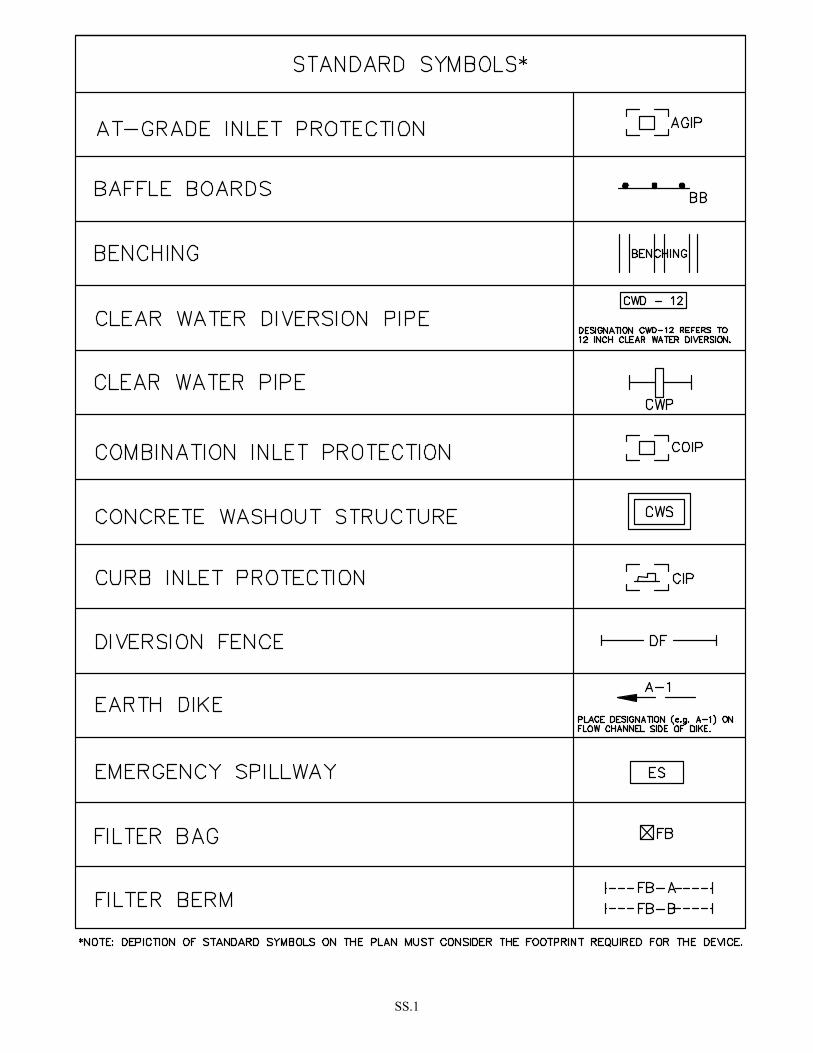
SS.1
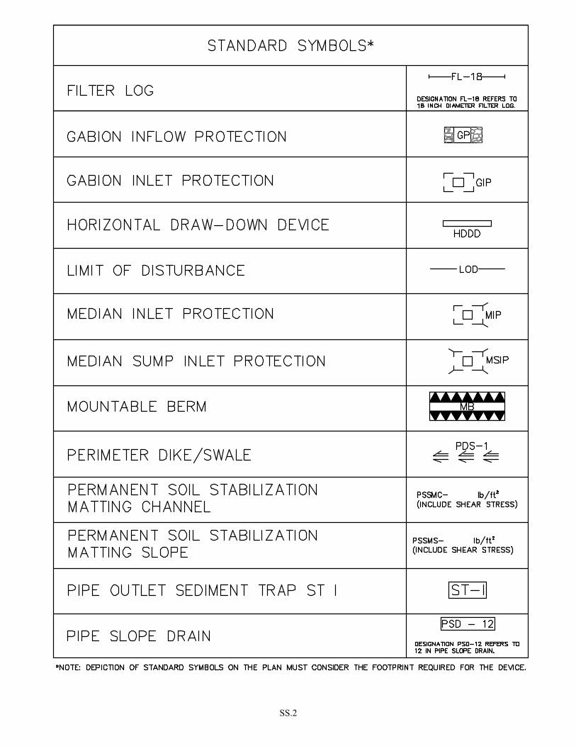
SS.2

SS.3
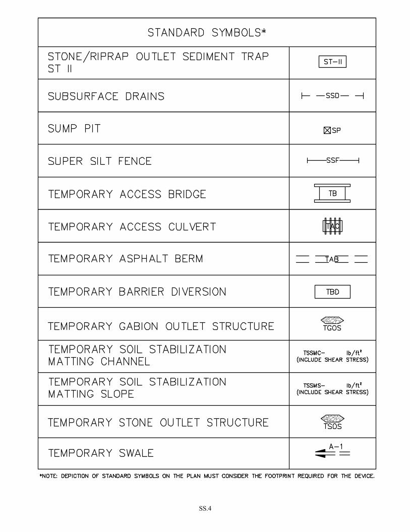
SS.4

SS.5


INTRODUCTION


I.1
PURPOSE The purpose of these Standards and Specifications for Soil Erosion and Sediment Control (Standards) is to establish minimum plan requirements and procedures to control the adverse impacts associated with soil erosion and sedimentation during construction. These Standards provide designers with a variety of measures to control sediment and stormwater related water quality problems caused by earth disturbance. These Standards are minimum criteria and must be incorporated into an overall approach for controlling runoff during construction. Environmental planning at the start of the site development process improves the effectiveness of the erosion and sediment plan, often resulting in a less costly project. An effective strategy depends largely on the designer's ability to select appropriate controls that address the unique characteristics and problems posed by a specific site. Ultimately, the success of the strategy relies on proper implementation and maintenance of the erosion and sediment control and stormwater management plans. Preventing soil erosion and off-site sedimentation will reduce impacts from land-disturbing activities and assist in the overall attainment and maintenance of water quality standards.
SEDIMENT DAMAGE Erosion on construction sites can be a significant source of sediment pollution to nearby streams. Excessive quantities of sediment cause costly damage to water resources and to private and public lands. Obstruction of stream channels and navigable rivers by sediment deposits reduces hydraulic capacity and increases flooding. Sediment deposits in drainage channels, culverts, and storm drainage systems result in frequent and costly maintenance. Municipal and industrial water supply reservoirs lose storage capacity. Navigable channels need to be dredged and, the cost of filtering and water purification increases. The negative impact on aquatic organisms due to large influxes of sediment into waterways is substantial. The initial effect is a reduction in the number and density of benthic macroinvertebrates. Aquatic vegetation is often destroyed, either by burial or reduction of sunlight essential for growth. Many species of fish, dependent on bottom dwelling organisms for food or plant life for refuge, are threatened by the damaged habitat. The reduction of sunlight from suspended sediment can reduce oxygen levels in the water to a point where aquatic life cannot survive. The habitat destruction associated with rapid sedimentation severely impairs the ability of water resources to support commercially important finfish and shellfish populations. Migratory waterfowl also depend on near-shore plant and shellfish communities as a food source during annual migration. The reduction of waterfowl has been associated, in part, with habitat destruction from sedimentation derived from development activity. Erosion and subsequent sedimentation of waterways also impacts recreational areas. The aesthetics and recreational value of streams, lakes and reservoirs used for swimming, boating, fishing and other water-related activities can be impaired from excessive sedimentation.
FACTORS THAT INFLUENCE SOIL EROSION The inherent erodibility of soils must be evaluated when designing a plan. The erosion potential of any area is determined by four principal factors: the erodibility of the soils, vegetative cover, topography, and climate. Although the factors are interrelated, they are discussed separately for ease of understanding.
Soil Erodibility The vulnerability of a soil to erosion is known as erodibility. Erodibility is influenced by soil particle size and gradation (texture), percentage of organic matter, and soil structure. Generally the most erodible soils contain high proportions of silt and very fine sand. The presence of clay or organic matter tends to decrease soil erodibility. Clays are sticky and tend to bind soil particles together, which along with
I.2
organic matter helps to maintain stable soil structure (aggregates). Vegetative Cover
There are several ways in which vegetation protects soil from erosive forces of rainfall. Vegetation shields the soil surface from the impact of raindrops while the root mass holds soil particles in place. Vegetation filters sediment, slows the velocity of runoff, and helps maintain the infiltration capacity of a soil. Maintaining and establishing vegetation are the most important factors in combating erosion. The goal is to expose as small an area as possible for the shortest length of time. By minimizing the time and extent of soil exposure, the erosion potential is reduced.
Topography
Slope length and steepness are key influences on both the volume and velocity of surface runoff. Longer slopes deliver more runoff to the base of slopes, and steeper slopes increase runoff velocity; both conditions enhance the potential for erosion.
Climate
Erosion potential is also affected by the climate of an area. Rainfall characteristics (i.e. frequency, intensity, and duration) directly influence the amount of runoff generated. As the frequency of rainfall increases, water has less chance between storms to drain through the soil.
The soil will remain saturated for longer periods of time and stormwater runoff volume will be greater when rainfall events are more frequent, intense, or lengthy. Seasonal variation in temperature and rainfall defines periods of high erosion potential during the year. May through September is the period of the year when higher soil loss rates are most likely to occur in Maryland. Snow will not cause erosion as it falls, but when rapid melts occur, erosion may result. Soil erosion and sedimentation can be reduced when soil, vegetative, topographic, and climatic factors are considered during the planning stage of development.

I.3
REVISING THE MARYLAND STANDARDS AND SPECIFICATIONS
These Standards establish the minimum requirements for individual practices used for erosion and sediment control in Maryland. On occasion, variations or new practices may be found to be effective for erosion and sediment control. Use of a new or revised practice requires that a detail and accompanying specifications be developed and submitted to the Maryland Department of the Environment, Water Management Administration (MDE/WMA). A subcommittee consisting of Natural Resources Conservation Service, State Soil Conservation Committee, Soil Conservation Districts, local governments, and MDE technical personnel will review the proposed erosion and sediment control practice. If the proposed practice is approved by the technical subcommittee, an authorization will be issued by MDE/WMA. Once approved, the practice may be used routinely, based on its acceptance by the appropriate approval authority.


SECTION A – PLANNING AND DESIGN


A.1
A-1 ENVIRONMENTAL SITE DESIGN (ESD) The Stormwater Management Act of 2007 (Act) defines Environmental Site Design (ESD) as “using small-scale stormwater management practices, nonstructural techniques, and site planning to mimic natural hydrologic runoff characteristics and minimize the impact of land development on water resources.” ESD emphasizes conserving natural features, drainage patterns, and vegetation; minimizing impervious surfaces; slowing down runoff; and increasing infiltration. The changes necessary to implement the Act are significant and require consideration of runoff control from the start of the land development process. As a result of the Act, the design and review of erosion and sediment control and stormwater management plans must be integrated. In addition, erosion and sediment control needs to be considered from the beginning planning stages. The definition of ESD, the modifications to the Code of Maryland Regulations (COMAR), and the procedures and practices presented herein will guide developers and designers in meeting Maryland’s sediment and stormwater requirements.

A.2
A-2 DESIGN AND REVIEW PROCESS Acceptable erosion and sediment control plans must be designed to mitigate soil erosion, prevent increases in stormwater runoff, and minimize the discharge of pollutants. The Act requires the establishment of a comprehensive process for the review and approval of erosion and sediment control and stormwater management plans. Planning for erosion and sediment control needs to start early and be integrated with stormwater management practices. A coordinated, comprehensive review process includes the submission and review of erosion and sediment control and stormwater management plans for each of the following three phases of plan development:
1. CONCEPT PLAN
2. SITE DEVELOPMENT PLAN
3. FINAL PLAN
This process is described in more detail in Chapter 5, Supplement #1, 2000 Maryland Stormwater Design Manual and outlined in Figure A.1 below.
Figure A.1: Design Process for New Development (Source: Chapter 5, Supplement #1, 2000 Maryland Stormwater Design Manual)

A.3
Concept Plan Developing a plan begins with gathering, mapping, and analyzing information about the physical characteristics of the site. The proposed development site should be visited in order to clearly understand its topographic, vegetative, drainage, and soil characteristics. Relying exclusively on topographic maps, soils maps, and other materials found in the office without field verification is not an acceptable planning technique. The topography of the site, mapped at suitable contour intervals, will allow the delineation of drainage areas, flow patterns, slopes, and natural resources such as wetlands, seeps, streams, forests, critical areas, and buffers. Downstream wetlands, lakes, streams, structures, Tier II waters, or other areas particularly sensitive to damage from erosion and sedimentation should also be investigated, mapped, and incorporated into the site design to afford these areas additional consideration. Investigating the site soil characteristics enables the designer to identify areas that should remain undisturbed. The concept plan requires mapping of natural resources, vegetative buffer strips, highly erodible soils, and slopes 15 percent and steeper. These mapped areas are to be protected from erosion using additional measures or, wherever possible, designated to remain undisturbed. This data will serve as the foundation for developing the site development plan for both erosion and sediment control and stormwater management. Site Development Plan The site development plan establishes the footprint of the proposed project and identifies the impacts of the proposed impervious surfaces on the existing natural conditions. This will better protect natural resources and buffers and allow for using ESD practices throughout the site. Included in this step is a narrative describing how erosion and sediment control will be integrated into the stormwater management strategy using ESD in accordance with The 2000 Maryland Stormwater Design Manual, Chapter 5, Supplement 1. Also included is the preparation of detailed designs, computations, and grading plans for a comprehensive review and approval. An overlay plan showing stormwater and erosion and sediment control practices is required as part of the site development submittal. After approval from the approval authority, the applicant will then proceed with final plan preparation. Final Plan Final erosion and sediment control plans must include the limit of disturbance (LOD), the location of each sediment control practice, contours for sediment traps and sediment basins, associated construction notes, details, and representative cross-sections, as appropriate. Depiction of standard symbols on the plan needs to consider the footprint required for the device. Existing and proposed contours need to be shown at an appropriate interval. Drainage areas must be delineated for sediment control practices whose sizing is based on the drainage area, and, when necessary, design computations must be provided. When phasing is necessary, the sediment control plan must include initial, interim, and final phase sediment control practices, as appropriate. A sequence of construction must be provided with enough detail to guide the construction, maintenance, and removal of the erosion and sediment controls.

A.4
A-3 SEDIMENT CONTROL PRINCIPLES The principles listed in Table A.1 should be followed in developing erosion and sediment control plans that prevent erosion, protect against downstream erosion, capture sediment on-site, and meet applicable requirements.
Table A.1: Planning Principles
No. Planning Principle
1. Plan the development to fit the site
2. Protect and avoid natural resources
3. Protect and avoid steep slopes and highly erodible soils
4. Minimize disturbed areas
5. Stabilize exposed soils as soon as practicable
6. Control and/or manage on-site and off-site runoff
7. Protect perimeter areas and retain sediment on-site
8. Make provisions for inspecting and maintaining sediment controls
1. Plan the development to fit the site
A primary goal of ESD is the conservation of natural features (e.g., drainage patterns, soil, vegetation) to the maximum extent practicable (MEP). Working with a site’s natural features helps minimize the amount of clearing and grading. Using the existing contours as much as possible reduces cuts and fills. Fitting the development to the site often reduces the amount of cut and fill, the potential for erosion, the need for structural components, and the project cost.
2. Protect and avoid natural resources
Disturbed areas adjacent to natural resources require special attention. During the concept plan stage, a site’s natural resource areas, such as wetlands, springheads, floodplains and stream buffers, are to be mapped.
Protecting natural resources includes avoidance and minimization. If avoidance is not feasible, every effort must be made to minimize impacts. Construction resulting in temporary impacts to natural resources may require enhanced management, such as accelerated stabilization, redundant erosion and sediment controls, and increased vegetative buffers. If a project is in Tier II waters or discharges to an impaired water body with a Total Maximum Daily Load (TMDL) allocation for sediment, an additional level of control(s) may be needed. This includes but is not limited to accelerated stabilization, redundant controls, increased buffers, passive or active chemical treatment, or a reduction in the size of the grading unit. To protect Tier II Watersheds, a minimum 100-foot buffer (or larger depending on site soils and slopes) is recommended for all perennial and intermittent streams. Buffers may also be required by other State regulations or local criteria (e.g., wetlands and waterways, forest conservation, and critical area). Riparian buffering recommendations (adapted from Johnson, C.W. and Buffer, S. 2008) are provided below.
A.5
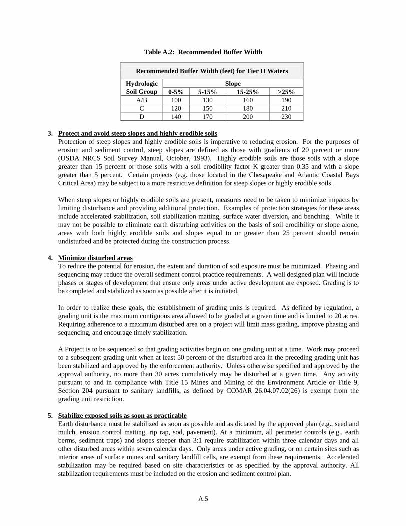
Table A.2: Recommended Buffer Width 3. Protect and avoid steep slopes and highly erodible soils
Protection of steep slopes and highly erodible soils is imperative to reducing erosion. For the purposes of erosion and sediment control, steep slopes are defined as those with gradients of 20 percent or more (USDA NRCS Soil Survey Manual, October, 1993). Highly erodible soils are those soils with a slope greater than 15 percent or those soils with a soil erodibility factor K greater than 0.35 and with a slope greater than 5 percent. Certain projects (e.g. those located in the Chesapeake and Atlantic Coastal Bays Critical Area) may be subject to a more restrictive definition for steep slopes or highly erodible soils. When steep slopes or highly erodible soils are present, measures need to be taken to minimize impacts by limiting disturbance and providing additional protection. Examples of protection strategies for these areas include accelerated stabilization, soil stabilization matting, surface water diversion, and benching. While it may not be possible to eliminate earth disturbing activities on the basis of soil erodibility or slope alone, areas with both highly erodible soils and slopes equal to or greater than 25 percent should remain undisturbed and be protected during the construction process.
4. Minimize disturbed areas
To reduce the potential for erosion, the extent and duration of soil exposure must be minimized. Phasing and sequencing may reduce the overall sediment control practice requirements. A well designed plan will include phases or stages of development that ensure only areas under active development are exposed. Grading is to be completed and stabilized as soon as possible after it is initiated. In order to realize these goals, the establishment of grading units is required. As defined by regulation, a grading unit is the maximum contiguous area allowed to be graded at a given time and is limited to 20 acres. Requiring adherence to a maximum disturbed area on a project will limit mass grading, improve phasing and sequencing, and encourage timely stabilization.
A Project is to be sequenced so that grading activities begin on one grading unit at a time. Work may proceed to a subsequent grading unit when at least 50 percent of the disturbed area in the preceding grading unit has been stabilized and approved by the enforcement authority. Unless otherwise specified and approved by the approval authority, no more than 30 acres cumulatively may be disturbed at a given time. Any activity pursuant to and in compliance with Title 15 Mines and Mining of the Environment Article or Title 9, Section 204 pursuant to sanitary landfills, as defined by COMAR 26.04.07.02(26) is exempt from the grading unit restriction.
5. Stabilize exposed soils as soon as practicable Earth disturbance must be stabilized as soon as possible and as dictated by the approved plan (e.g., seed and mulch, erosion control matting, rip rap, sod, pavement). At a minimum, all perimeter controls (e.g., earth berms, sediment traps) and slopes steeper than 3:1 require stabilization within three calendar days and all other disturbed areas within seven calendar days. Only areas under active grading, or on certain sites such as interior areas of surface mines and sanitary landfill cells, are exempt from these requirements. Accelerated stabilization may be required based on site characteristics or as specified by the approval authority. All stabilization requirements must be included on the erosion and sediment control plan.
Recommended Buffer Width (feet) for Tier II Waters
Slope Hydrologic Soil Group 0-5% 5-15% 15-25% >25%
A/B 100 130 160 190 C 120 150 180 210 D 140 170 200 230
A.6
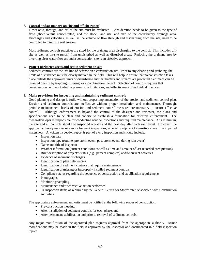
6. Control and/or manage on-site and off-site runoff Flows onto, through, and off of the site must be evaluated. Consideration needs to be given to the type of flow (sheet versus concentrated) and the slope, land use, and size of the contributory drainage area. Discharges and velocities, as well as the volume of flow through and discharging from the site, need to be controlled to minimize soil erosion. Most sediment controls practices are sized for the drainage area discharging to the control. This includes off-site as well as on-site runoff, from undisturbed as well as disturbed areas. Reducing the drainage area by diverting clear water flow around a construction site is an effective approach.
7. Protect perimeter areas and retain sediment on-site
Sediment controls are the last line of defense on a construction site. Prior to any clearing and grubbing, the limits of disturbance must be clearly marked in the field. This will help to ensure that no construction takes place outside the approved limits of disturbance and that buffers and streams are protected. Sediment can be retained on-site by trapping, filtering, or a combination thereof. Selection of controls requires that consideration be given to drainage areas, site limitations, and effectiveness of individual practices.
8. Make provisions for inspecting and maintaining sediment controls
Good planning and design is futile without proper implementation of the erosion and sediment control plan. Erosion and sediment controls are ineffective without proper installation and maintenance. Thorough, periodic maintenance checks of erosion and sediment control measures are necessary to ensure effective control. Although enforcement is beyond the control of the designer and reviewer, the plans and specifications need to be clear and concise to establish a foundation for effective enforcement. The owner/developer is responsible for conducting routine inspections and required maintenance. At a minimum, the site and all controls should be inspected weekly and the next day after each rain event. However, the approval authority may require more frequent inspections, especially adjacent to sensitive areas or in impaired watersheds. A written inspection report is part of every inspection and should include:
• Inspection date • Inspection type (routine, pre-storm event, post-storm event, during rain event) • Name and title of inspector • Weather information (current conditions as well as time and amount of last recorded precipitation) • Brief description of project’s status (e.g., percent complete) and/or current activities • Evidence of sediment discharges • Identification of plan deficiencies • Identification of sediment controls that require maintenance • Identification of missing or improperly installed sediment controls • Compliance status regarding the sequence of construction and stabilization requirements • Photographs • Monitoring/sampling • Maintenance and/or corrective action performed • Or inspection items as required by the General Permit for Stormwater Associated with Construction
Activities
The appropriate enforcement authority must be notified at the following stages of construction: • Pre-construction meeting; • After installation of sediment controls for each phase; and • After permanent stabilization and prior to removal of sediment controls.
Any major modification of the approved plan requires approval from the appropriate authority. Minor modifications may be made in the field if approved by the inspector and documented in a field inspection report.

A.7
A-4 DESIGN METHODOLOGY The design of erosion and sediment control needs to be integrated with the stormwater management plan. Table A.3 outlines the steps necessary for an erosion and sediment control plan to achieve ESD to the MEP. A more detailed description of each step follows the table.
Table A.3: Design Steps
No. Design Step
1. Identify existing drainage patterns, drainage area boundaries, and slopes (concept plan)
2. Identify areas of special concern (concept plan)
3. Fingerprint site and layout development (concept and site development plans)
4. Determine phasing requirements and select initial erosion and sediment controls (site development and final plans)
5. Identify interim drainage patterns, drainage area boundaries, and slopes; and select interim controls (site development and final plans)
6. Identify proposed drainage patterns, drainage area boundaries, and slopes; and select final controls (site development and final plans)
7. Prepare the sequence(s) of construction (site development and final plans)
1. Identify existing drainage patterns, drainage area boundaries, and slopes Current drainage information for the project site as well as off-site needs to be obtained and verified through a site visit or survey. Field check drainage patterns, drainage boundaries, vegetation, and land use. Look for existing storm drains, culverts, underground utilities, and other drainage features. Evaluate flow onto, through, and off of the site for existing conditions. Examine drainage areas to determine the size, slope, slope length, flow path, and, for areas with concentrated flow, the discharge. Decide if off-site flow can be diverted through or around the site. Using ESD principles, maintain or mimic the existing drainage patterns that give preference to sheet flow and small drainage areas.
2. Identify areas of special concern
Areas of particular environmental concern, such as wetlands, streams, buffers, wooded areas, slopes 15 percent and steeper, and highly erodible soils, need to be identified within both the project site and adjacent areas and shown on the plan. Other considerations include the Chesapeake and Atlantic Coastal Bays Critical Area; National Wetland Inventory; natural heritage areas; rare, threatened, and endangered species habitat; Tier II watersheds (see Tier II buffer recommendations in Table A.2); and impaired stream segments with a TMDL for sediment. Areas of special concern must be verified with a site visit. Note any erosion, lack of vegetation, drainage problems, and other features that may be pertinent to the design. If an unmapped resource is found, contact the appropriate authority to determine additional regulatory requirements.
A.8
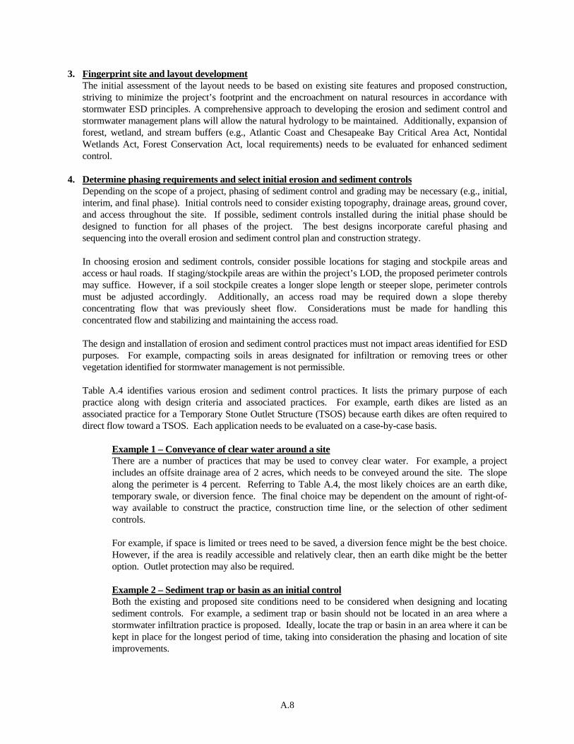
3. Fingerprint site and layout development The initial assessment of the layout needs to be based on existing site features and proposed construction, striving to minimize the project’s footprint and the encroachment on natural resources in accordance with stormwater ESD principles. A comprehensive approach to developing the erosion and sediment control and stormwater management plans will allow the natural hydrology to be maintained. Additionally, expansion of forest, wetland, and stream buffers (e.g., Atlantic Coast and Chesapeake Bay Critical Area Act, Nontidal Wetlands Act, Forest Conservation Act, local requirements) needs to be evaluated for enhanced sediment control.
4. Determine phasing requirements and select initial erosion and sediment controls
Depending on the scope of a project, phasing of sediment control and grading may be necessary (e.g., initial, interim, and final phase). Initial controls need to consider existing topography, drainage areas, ground cover, and access throughout the site. If possible, sediment controls installed during the initial phase should be designed to function for all phases of the project. The best designs incorporate careful phasing and sequencing into the overall erosion and sediment control plan and construction strategy.
In choosing erosion and sediment controls, consider possible locations for staging and stockpile areas and access or haul roads. If staging/stockpile areas are within the project’s LOD, the proposed perimeter controls may suffice. However, if a soil stockpile creates a longer slope length or steeper slope, perimeter controls must be adjusted accordingly. Additionally, an access road may be required down a slope thereby concentrating flow that was previously sheet flow. Considerations must be made for handling this concentrated flow and stabilizing and maintaining the access road. The design and installation of erosion and sediment control practices must not impact areas identified for ESD purposes. For example, compacting soils in areas designated for infiltration or removing trees or other vegetation identified for stormwater management is not permissible.
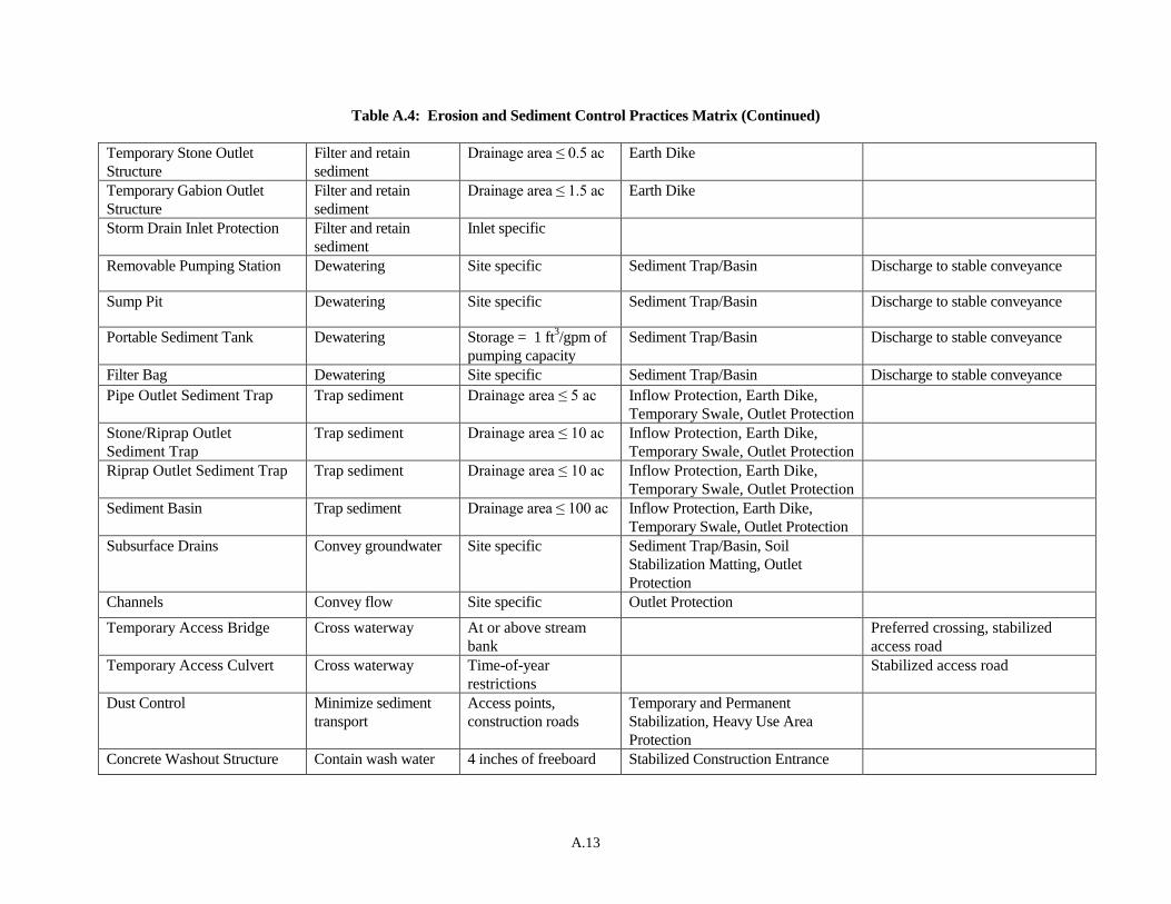
Table A.4 identifies various erosion and sediment control practices. It lists the primary purpose of each practice along with design criteria and associated practices. For example, earth dikes are listed as an associated practice for a Temporary Stone Outlet Structure (TSOS) because earth dikes are often required to direct flow toward a TSOS. Each application needs to be evaluated on a case-by-case basis.
Example 1 – Conveyance of clear water around a site There are a number of practices that may be used to convey clear water. For example, a project includes an offsite drainage area of 2 acres, which needs to be conveyed around the site. The slope along the perimeter is 4 percent. Referring to Table A.4, the most likely choices are an earth dike, temporary swale, or diversion fence. The final choice may be dependent on the amount of right-of-way available to construct the practice, construction time line, or the selection of other sediment controls. For example, if space is limited or trees need to be saved, a diversion fence might be the best choice. However, if the area is readily accessible and relatively clear, then an earth dike might be the better option. Outlet protection may also be required.
Example 2 – Sediment trap or basin as an initial control Both the existing and proposed site conditions need to be considered when designing and locating sediment controls. For example, a sediment trap or basin should not be located in an area where a stormwater infiltration practice is proposed. Ideally, locate the trap or basin in an area where it can be kept in place for the longest period of time, taking into consideration the phasing and location of site improvements.

A.9
The sequencing of a site must take into account the time and access needed to install the initial sediment controls. If earth dikes and a sediment basin are designed as the initial controls, these must be completed before beginning other grading. This could require stockpiling the excavated material from the basin rather than using it immediately for fill on the site. Sequencing is also important to ensure that the basin is completed prior to the construction of the berms. Additional sediment controls may be required if extensive clearing is needed to reach the proposed basin location.
Example 3 – Concentrated flow A 1.2 acre project site is located at the bottom of a 5 acre drainage area. The clear water runoff from the 3.8 acres off-site area is going to be diverted around the project site. Because of site constraints, the flow leaving the site will be concentrated. Referring to Table A.4, the potential practices include storm drain inlet protection, sediment traps, sediment basins, temporary stone outlet structures, and temporary gabion outlet structures (TGOS). The table indicates that silt fence, super silt fence, filter berms, and similar practices are not acceptable since these are limited to sheet flow. Because the drainage area is greater than an acre, selection is limited to two practices: a sediment trap or a TGOS.
5. Identify interim drainage patterns, drainage area boundaries, and slopes; and select interim controls
Interim conditions are often overlooked yet are important considerations for erosion and sediment control design. Typically, evaluating interim conditions is more difficult than evaluating initial phase or final phase. Project plans always include existing and proposed site conditions. Unlike the initial or final phases, interim conditions are not definitive; they represent the in-between. Due to shifts in drainage areas and changes in slope, drainage patterns for an interim phase may be entirely different from initial or final phase, and therefore the sediment controls may also need to be different. To select interim controls, apply the same procedures used to select initial phase sediment controls. Initial and final phase controls may need to be adjusted or modified to better correlate with the interim phase controls. Depending on the scope of the project, an interim phase sediment control plan may not be required.
Example 4 – Interim changes in drainage and slope A subdivision is being constructed and will require various amounts of cut and fill to accommodate roadway and public sewer installation. Initial clearing, grubbing, and perimeter control installation have occurred. For the most part, sheet flow has been maintained during the rough grading stage. However, as roads are established and lots brought to grade, both drainage area and flow regimes (e.g., sheet flow to concentrated flow) have changed. Therefore, perimeter controls that accommodate concentrated flows (e.g., dikes and swales) would be more appropriate than those that are used for sheet flow conditions (e.g., silt fence or super silt fence). Similarly, the designer needs to consider the design and construction constraints for individual controls. Additionally, the vertical transition resulting from grade changes and slope increases from the roadway fills needs to be addressed. As fill progresses, runoff may need to be conveyed safely from the top of the slope to the bottom using pipe slope drains. Consideration also has to be given to the conveyance of this runoff to a sediment trapping practice.
6. Identify proposed drainage patterns, drainage area boundaries, and slopes; and select final controls
Follow the same procedures used to select initial phase sediment controls. Initial and interim phase controls may need to be adjusted or modified to better correlate with the final phase plans. As construction progresses, consider impacts to staging and stockpile areas and access roads. Also, consideration needs to be given to how the controls selected for final phase will be removed.
Example 5 – Final phase plan Construction of a 14 acre housing development is initially controlled by three sediment traps and associated earth dike. Off-site drainage is not an issue. As roads are installed and house lots brought to grade, some of the disturbed area will no longer be conveyed to the traps, necessitating the design
A.10
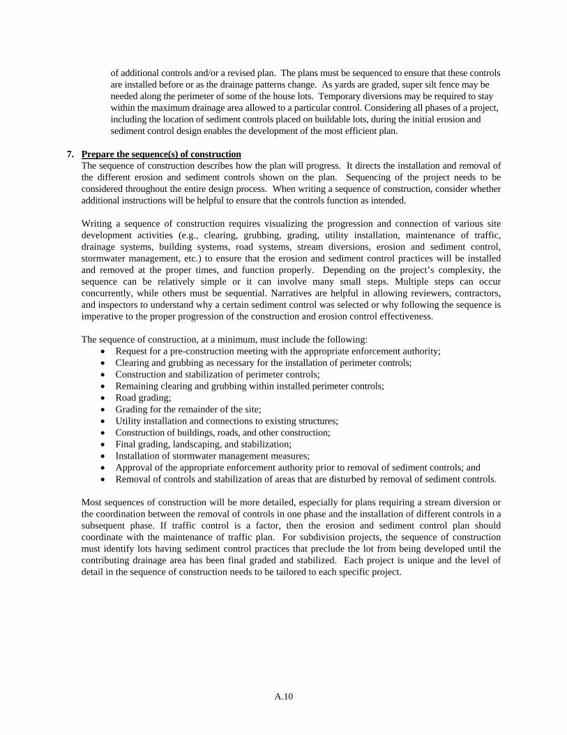
of additional controls and/or a revised plan. The plans must be sequenced to ensure that these controls are installed before or as the drainage patterns change. As yards are graded, super silt fence may be needed along the perimeter of some of the house lots. Temporary diversions may be required to stay within the maximum drainage area allowed to a particular control. Considering all phases of a project, including the location of sediment controls placed on buildable lots, during the initial erosion and sediment control design enables the development of the most efficient plan.
7. Prepare the sequence(s) of construction
The sequence of construction describes how the plan will progress. It directs the installation and removal of the different erosion and sediment controls shown on the plan. Sequencing of the project needs to be considered throughout the entire design process. When writing a sequence of construction, consider whether additional instructions will be helpful to ensure that the controls function as intended.
Writing a sequence of construction requires visualizing the progression and connection of various site development activities (e.g., clearing, grubbing, grading, utility installation, maintenance of traffic, drainage systems, building systems, road systems, stream diversions, erosion and sediment control, stormwater management, etc.) to ensure that the erosion and sediment control practices will be installed and removed at the proper times, and function properly. Depending on the project’s complexity, the sequence can be relatively simple or it can involve many small steps. Multiple steps can occur concurrently, while others must be sequential. Narratives are helpful in allowing reviewers, contractors, and inspectors to understand why a certain sediment control was selected or why following the sequence is imperative to the proper progression of the construction and erosion control effectiveness. The sequence of construction, at a minimum, must include the following:
• Request for a pre-construction meeting with the appropriate enforcement authority; • Clearing and grubbing as necessary for the installation of perimeter controls; • Construction and stabilization of perimeter controls; • Remaining clearing and grubbing within installed perimeter controls; • Road grading; • Grading for the remainder of the site; • Utility installation and connections to existing structures; • Construction of buildings, roads, and other construction; • Final grading, landscaping, and stabilization; • Installation of stormwater management measures; • Approval of the appropriate enforcement authority prior to removal of sediment controls; and • Removal of controls and stabilization of areas that are disturbed by removal of sediment controls.
Most sequences of construction will be more detailed, especially for plans requiring a stream diversion or the coordination between the removal of controls in one phase and the installation of different controls in a subsequent phase. If traffic control is a factor, then the erosion and sediment control plan should coordinate with the maintenance of traffic plan. For subdivision projects, the sequence of construction must identify lots having sediment control practices that preclude the lot from being developed until the contributing drainage area has been final graded and stabilized. Each project is unique and the level of detail in the sequence of construction needs to be tailored to each specific project.

A.11
Table A.4: Erosion and Sediment Control Practices Matrix
Practice Primary Purpose Design Criteria Associated Practices Remarks
Stabilized Construction
Entrance
Stabilize surface Access points Gravel Berm, Silt Fence, Super Silt
Fence
All ingress/egress points
Stabilized Construction
Entrance with Wash Rack
Stabilize surface;
prevent tracking of
mud
Access points Sediment Traps, Gravel Berm,
Silt Fence, Super Silt Fence
All ingress/egress points
Serrated Slopes Stabilize extreme
grade changes
Site specific Temporary and Permanent
Stabilization
Divert overland flow from top of
slope
Benching Minimize erosion 20 ft cut/fill- 2:1 slopes
30 ft cut/fill- 3:1 slopes
40 ft cut/fill- 4:1 slopes
Temporary and Permanent
Stabilization, Pipe Slope Drain
Can apply to stockpiles
Temporary Stabilization Stabilize soil Site specific Soil Stabilization Matting Maximum six month duration, soil
testing
Permanent Stabilization Stabilize soil Site specific Soil Stabilization Matting Soil testing
Soil Stabilization Matting Stabilize soil Slope, slope length,
soil erodibility, velocity
Temporary and Permanent
Stabilization
Heavy Use Area Protection Stabilize surface Construction routes,
staging and material
storage areas
Dust Control, Stabilized
Construction Entrance
Stockpile Area Store earth Site specific Stabilized Construction Entrance,
Silt Fence, Super Silt Fence, TSOS,
Earth Dikes, Outlet Protection
Earth Dike Convey runoff Drainage area ≤ 10 ac;
slope ≤ 10%
Sediment Trap, TSOS, TGOS,
Outlet Protection
Engineering design if > 10 ac or
slope > 10%.
Temporary Swale Convey runoff Drainage area ≤ 10 ac;
slope ≤ 10%
Sediment Trap, TSOS, TGOS;
Outlet Protection
Engineering design if > 10 ac or
slope > 10%.
Perimeter Dike/ Swale Convey runoff Drainage area ≤ 2 ac;
slope ≤ 10%
Sediment Trap, Temporary
Stabilization
Smaller footprint than earth dike
and temporary swale
Temporary Storm Drain
Diversion
Convey runoff Site specific Sediment Trap or Basin, Outlet
Protection,
Temporary Asphalt Berm Convey runoff on
paved areas
Site specific Earth Dikes, TSOS, TGOS,
Outlet Protection

A.12
Table A.4: Erosion and Sediment Control Practices Matrix (Continued)
Clear Water Diversion Pipe Convey concentrated
flow around
construction area
Design storm = Q2;
1 ft freeboard at inlet
Dewatering Practices,
Outlet Protection
Possible review by Wetlands and
Waterways Program
Temporary Barrier Diversion Convey runoff around
construction
Design storm = Q2;
1 ft freeboard at inlet
Dewatering Practices;
Outlet Protection
Mountable Berm Convey runoff Side slopes ≤ 5:1;
minimum height 18 in.
Earth Dike
Diversion Fence Convey runoff Drainage area ≤ 2 ac Sediment Trap, Earth Dike, TSOS,
TGOS, Outlet Protection
Smaller footprint than other
diversions; may not be applicable
in areas with bedrock
Pipe Slope Drain Convey runoff down
slopes
Drainage area ≤ 5 ac Earth Dike, Rock Outlet Protection,
Sediment Traps, TSOS, TGOS
Typically used for cut/fill slopes
Stone Check Dam Minimize erosion,
reduce velocities
Velocity > 4 fps Soil Stabilization Matting,
Sediment Trap, TSOS, TGOS
Velocity check, not a sediment
control
Riprap Inflow Protection Convey runoff
non-erosively
Inflow slopes between
4:1 and 10:1
Sediment Traps/Basins, Temporary
Swales, Earth Dike
Gabion Inflow Protection Convey runoff non-
erosively
Inflow slopes steeper
than 4:1
Sediment Traps/Basins, Temporary
Swales, Earth Dike
Rock Outlet Protection and
Plunge Pools
Prevent erosion at
outlets
Site specific Earth Dikes, Temporary Swales,
Sediment Basins, Sediment Traps,
PSD, Clear Water Diversion Pipe
Points of concentrated discharge
with erosive velocities
Silt Fence Filter and retain
sediment
Sheet flow from 5:1
slopes or flatter
Filter Berms/Logs, Super Silt Fence,
Stabilized Construction Entrance
Silt Fence on Pavement Filter and retain
sediment
Sheet flow from 3:1
slopes or flatter
Silt Fence, Super Silt Fence Used on pavement
Super Silt Fence Filter and retain
sediment
Sheet flow from 2:1
slopes or flatter
Filter Berms/Logs, Silt Fence,
Stabilized Construction Entrance
Clear Water Pipe through
Silt Fence/Super Silt Fence
Convey clear-water
runoff through
SF/SSF
Site specific Silt Fence, Super Silt Fence, Pipe
Slope Drain
Filter Berm Filter and retain
sediment
Sheet flow Silt Fence, Super Silt Fence,
Stabilized Construction Entrance
Used where penetration of the
ground is not desirable
Filter Log Filter and retain
sediment
Sheet flow from 2:1
slopes or flatter
Silt Fence, Super Silt Fence,
Stabilized Construction Entrance
A.13
Table A.4: Erosion and Sediment Control Practices Matrix (Continued)
Temporary Stone Outlet
Structure
Filter and retain
sediment
Drainage area ≤ 0.5 ac Earth Dike
Temporary Gabion Outlet
Structure
Filter and retain
sediment
Drainage area ≤ 1.5 ac Earth Dike
Storm Drain Inlet Protection Filter and retain
sediment
Inlet specific
Removable Pumping Station Dewatering Site specific Sediment Trap/Basin Discharge to stable conveyance
Sump Pit Dewatering Site specific Sediment Trap/Basin Discharge to stable conveyance
Portable Sediment Tank Dewatering Storage = 1 ft3/gpm of
pumping capacity
Sediment Trap/Basin Discharge to stable conveyance
Filter Bag Dewatering Site specific Sediment Trap/Basin Discharge to stable conveyance
Pipe Outlet Sediment Trap Trap sediment Drainage area ≤ 5 ac Inflow Protection, Earth Dike,
Temporary Swale, Outlet Protection
Stone/Riprap Outlet
Sediment Trap
Trap sediment Drainage area ≤ 10 ac Inflow Protection, Earth Dike,
Temporary Swale, Outlet Protection
Riprap Outlet Sediment Trap Trap sediment Drainage area ≤ 10 ac Inflow Protection, Earth Dike,
Temporary Swale, Outlet Protection
Sediment Basin Trap sediment Drainage area ≤ 100 ac Inflow Protection, Earth Dike,
Temporary Swale, Outlet Protection
Subsurface Drains Convey groundwater Site specific Sediment Trap/Basin, Soil
Stabilization Matting, Outlet
Protection
Channels Convey flow Site specific Outlet Protection
Temporary Access Bridge Cross waterway At or above stream
bank
Preferred crossing, stabilized
access road
Temporary Access Culvert Cross waterway Time-of-year
restrictions
Stabilized access road
Dust Control Minimize sediment
transport
Access points,
construction roads
Temporary and Permanent
Stabilization, Heavy Use Area
Protection
Concrete Washout Structure Contain wash water 4 inches of freeboard Stabilized Construction Entrance
A.14
A-5 EROSION AND SEDIMENT CONTROL PLAN
The “Stormwater Management Act of 2007” and COMAR 26.17.02 regulations require concept, site
development, and final plans. It is essential that the erosion and sediment control plan be integrated with the
stormwater management plan to address these different stages of plan development and attain effective
resource protection. The key component of the concept phase from the erosion and sediment control
perspective is identifying highly erodible soils and steep slopes. For the site development and final plans,
specific erosion and sediment control practices will be detailed.
I. Content of the Erosion and Sediment Control Plan
Applicants are responsible for submitting an erosion and sediment control plan that meets the requirements
established by these Standards. The plan must include sufficient information to evaluate the site
conditions, environmental characteristics of the affected areas, potential impacts of the proposed grading
on water resources, and effectiveness and acceptability of measures proposed to prevent soil erosion and
off-site sedimentation.
Applicants shall submit the following information, at a minimum:
A. A letter of transmittal and/or application;
B. Name, address, and telephone number of:
1. The owner of the property where the grading is proposed;
2. The developer; and
3. The applicant;
C. A vicinity map indicating north arrow, scale, site location, and other information necessary to easily
locate the property;
D. Drainage area map(s) at a 1" = 200' minimum scale showing existing, interim, and proposed
topography, proposed improvements, standard symbols for proposed sediment control features, and
pertinent drainage information including provisions to protect downstream areas from erosion for a
minimum of 200 feet downstream or to the next conveyance system;
E. The location of natural resources, wetlands, floodplains, highly erodible soils, slopes 15 percent and
steeper, and any other sensitive areas required on a concept plan;
F. A general description of the predominant soil types on the site, as described by the appropriate soil
survey information available through the local soil conservation district or the USDA Natural
Resources Soil Conservation Service;
G. Proposed stormwater management practices;
H. Erosion and sediment control plans (site development and final) including:
1. The existing topography and improvements as well as proposed topography and
improvements at a scale between 1" = 10' and 1" = 50' with 2 foot contours or other approved
contour interval. For projects with more than minor grading, interim contours may also be
required;
2. Scale, project and sheet title, and north arrow on each plan sheet;
A.15
3. The limit of disturbance (LOD) including:
a. Limit of grading (grading units, if applicable), and
b. Initial, interim, and final phases;
4. The proposed grading and earth disturbance including:
a. Total disturbed area,
b. Volume of cut and fill quantities, and
c. Volume of borrow and spoil quantities;
5. Storm drainage features, including:
a. Existing and proposed bridges, storm drains, culverts, outfalls, etc.,
b. Velocities (v2 and v10) and flow rates (Q2 and Q10) at outfalls, and
c. Site conditions around points of all surface water discharge from the site;
6. Erosion and sediment control practices to minimize on-site erosion and prevent off-site
sedimentation including:
a. The salvage and reuse of topsoil,
b. Phased construction and implementation of grading unit(s) to minimize disturbances,
both in extent and duration,
c. Location and type of all proposed sediment control practices,
d. Design details and data for all erosion and sediment control practices, and
e. Specifications for temporary and permanent stabilization measures including, at a
minimum:
i. The following “Standard Stabilization Note” on the plan;
ii. Details for areas requiring accelerated stabilization;
iii. Maintenance requirements as defined in these Standards;
iv. Identification of interior areas of surface mines exempted from stabilization
requirements to prevent contamination of the recoverable resource by the
stabilization material;
7. A sequence of construction describing the relationship between the implementation and
maintenance of controls, including permanent and temporary stabilization, and the various
stages or phases of earth disturbance and construction. The sequence of construction, at a
minimum, must include the following:
a. Request for a pre-construction meeting with the appropriate enforcement authority;
b. Clearing and grubbing as necessary for the installation of perimeter controls;
c. Construction and stabilization of perimeter controls;
Standard Stabilization Note
Following initial soil disturbance or re-disturbance, permanent or temporary
stabilization must be completed within:
a.) Three (3) calendar days as to the surface of all perimeter dikes, swales, ditches,
perimeter slopes, and all slopes steeper than 3 horizontal to 1 vertical (3:1); and
b.) Seven (7) calendar days as to all other disturbed or graded areas on the project site
not under active grading.

A.16
d. Remaining clearing and grubbing within installed perimeter controls;
e. Road grading;
f. Grading for the remainder of the site;
g. Utility installation and connections to existing structures;
h. Construction of buildings, roads, and other construction;
i. Final grading, landscaping, and stabilization;
j. Installation of stormwater management measures;
k. Approval of the appropriate enforcement authority prior to removal of sediment
controls; and
l. Removal of controls and stabilization of areas that are disturbed by removal of
sediment controls.
Note: Any changes or revisions to the sequence of construction must be reviewed and
approved by the plan approval authority prior to proceeding with construction.
8. A statement requiring the owner/developer or representative to contact the appropriate
enforcement authority or its agent at the following stages of the project or in accordance with
the approved erosion and sediment control plan, grading permit, or building permit:
a. Prior to the start of earth disturbance,
b. Upon completion of the installation of perimeter erosion and sediment controls, but
before proceeding with any other earth disturbance or grading,
c. Prior to the start of another phase of construction or opening of another grading unit,
d. Prior to the removal of sediment control practices;
9. Certification by the owner or developer that any clearing, grading, construction, or
development will be done pursuant to the approved erosion and sediment control plan,
including inspecting and maintaining controls, and that the responsible personnel involved in
the construction project will have a Certificate of Training at a Maryland Department of the
Environment (MDE) approved training program for the control of erosion and sediment prior
to beginning the project. Additionally, the owner or developer shall certify right of entry for
periodic on-site evaluation by the appropriate enforcement authority and/or MDE;
10. If required by the appropriate approval authority or MDE, certification by a professional
engineer, land surveyor, landscape architect, architect, or forester (for forest harvest
operations only) registered in the State that the plans have been designed in accordance with
erosion and sediment control laws, regulations, and standards.
I. Any additional information or data deemed appropriate by the approval authority.
II. Approvals
Approved plans are required prior to commencing with earth disturbance.
A. Approval Requirements. An erosion and sediment control plan may be approved by the appropriate
approval authority once all requirements of these Standards have been met.
B. Approval Conditions. In granting the plan approval, the approval authority may impose additional
conditions and criteria as deemed necessary to ensure compliance with the provisions of these
Standards and the preservation of the State’s natural assets, resources, public health, and safety.
Generally, additional controls will be required in environmentally sensitive areas, areas with highly
erodible soils, or other facilities that require protection.

A.17
C. Suspension or Revocation. Any erosion and sediment control approval issued may be suspended or
revoked after written notice is given for any of the following reasons or as determined by the
appropriate approval authority:
1. Terms or conditions of the approved erosion and sediment control plans were violated;
2. Violation notice(s) or stop work order(s) were ignored;
3. Site characteristics upon which plan approval was based were changed; or
4. Construction standards as required by the approved plan were disregarded.
D. Modification of Approved Erosion and Sediment Control Plans. Modifications of an approved
erosion and sediment control plan must be made in accordance with the erosion and sediment control
criteria contained in these Standards and/or as directed by the enforcement authority. A written
statement explaining the change(s), all revised plan sheets, and any necessary revisions to the report
must be provided.


SECTION B – GRADING AND STABILIZATION

B.1
B-1 STANDARDS AND SPECIFICATIONS
FOR
STABILIZED CONSTRUCTION ENTRANCE
Definition A layer of aggregate that is underlain with nonwoven geotextile at points of ingress and egress of the construction site.
Purpose To reduce tracking of sediment onto roadways and provide a stable area for entrance to or exit from the construction site.
Conditions Where Practice Applies Stabilized construction entrances must be located at all points of construction ingress and egress.
Design Criteria 1. Where possible, locate the stabilized construction entrances at the high side of the project area. 2. For single family residential lots, locate the entrance at the permanent driveway. 3. Stabilized construction entrances cannot be installed over pavement. 4. Minimum length is 50 feet (30 feet for single family residential lots). 5. Minimum width is 10 feet. Flare entrance 10 feet minimum at the existing road to provide a turning
radius. 6. The orientation of the stabilized construction entrance may vary from a straight line to a curve or "T"
shape depending on the topography and right-of-way.
7. All surface water flowing to or diverted toward the stabilized construction entrance (SCE) must be piped under the entrance. Size the pipe to convey the runoff generated by the 2-year, 24-hour frequency storm at minimum. The minimum permissible pipe size is 6 inches. When the entrance is located at a high spot and has no drainage to convey, a pipe is not necessary.
Maintenance
The SCE must be maintained in a condition that minimizes tracking of sediment. This may require adding stone or making other repairs as conditions demand to maintain a clean surface, the mountable berm, and the specified dimensions. All stone or sediment spilled, dropped, or tracked onto the adjacent roadway must be removed immediately by vacuuming, scraping, and/or sweeping. Washing the roadway to remove mud tracked onto pavement is not acceptable unless the wash water is directed to an approved sediment control practice.
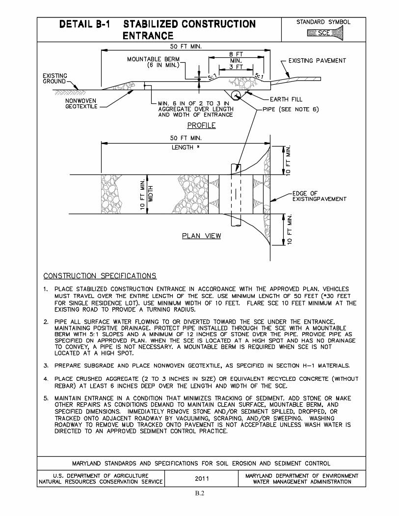
B.2
B.3
B-2 STANDARDS AND SPECIFICATIONS
FOR
WASH RACK OPTION
Definition
A system used in conjunction with a stabilized construction entrance (SCE) for washing mud off construction vehicle wheels.
Purpose
To reduce tracking wherever conditions require washing the construction vehicle wheels prior to exiting the site.
Conditions Where Practice Applies SCE with wash racks are located at points of ingress and egress where tracking of mud and sediment cannot be removed through the use of conventional maintenance practices (e.g., sweeping, vacuuming, etc.).
Design Criteria
1. SCE with wash rack must drain to an approved sediment trapping device. 2. SCE with wash rack cannot be installed over existing pavement. 3. Wash rack must be designed of material that is constructed and manufactured to withstand the
anticipated traffic loads. Wash racks may be of concrete, steel, or other materials.
Maintenance
The area under the wash rack must be maintained free of accumulated sediment. If damaged, the wash rack must be repaired or replaced.
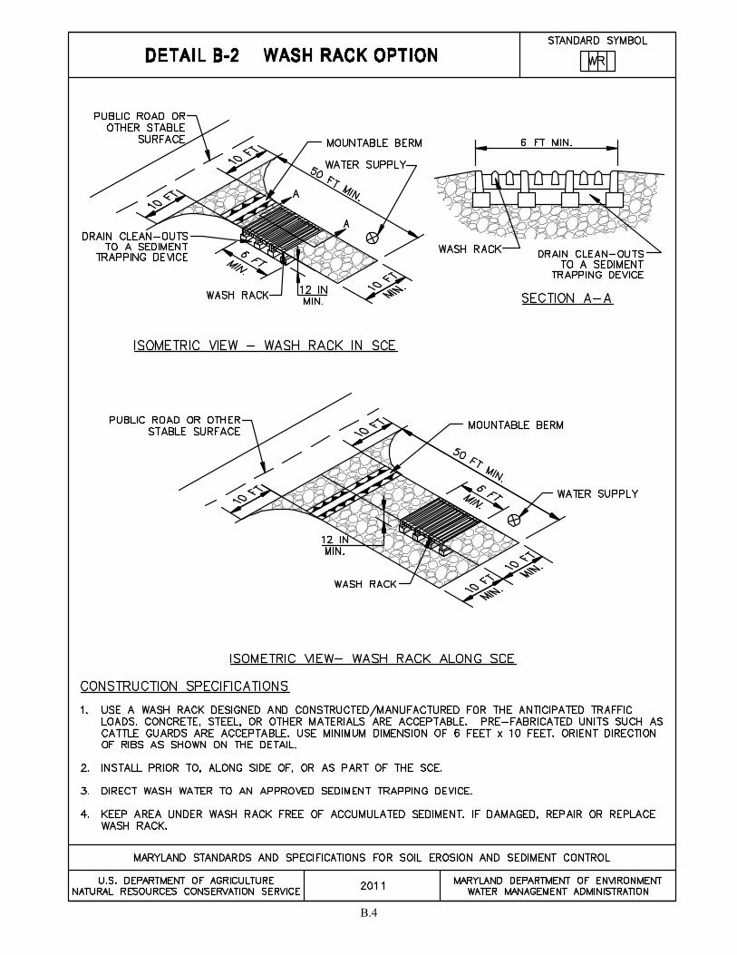
B.4
B.5
B-3 STANDARDS AND SPECIFICATIONS
FOR
LAND GRADING
Definition Reshaping the existing land surface to provide suitable topography for building facilities and other site improvements.
Purpose To provide erosion control and vegetative establishment for extreme changes in grade.
Conditions Where Practice Applies Earth disturbances or extreme grade modifications on steep or long slopes.
Design Criteria The grading plan should be based on the incorporation of building designs and street layouts that fit and utilize existing topography and desirable natural surroundings to avoid extreme grade modifications. Information submitted must provide sufficient topographic surveys and soil investigations to determine limitations that must be imposed on the grading operation related to slope stability, adjacent properties, drainage patterns, measures for water removal, and vegetative treatment, etc. Many jurisdictions have regulations and design procedures already established for land grading that must be followed. The plan must show existing and proposed contours for the area(s) to be graded including practices for erosion control, slope stabilization, and safe conveyance of runoff (e.g., waterways, lined channels, reverse benches, grade stabilization structures). The grading/construction plans are to include the phasing of these practices and consideration of the following:
1. Provisions to safely convey surface runoff to storm drains, protected outlets or stable water courses to ensure that surface runoff will not damage slopes or other graded areas.
2. Cut and fill slopes, stabilized with grasses, no steeper than 2:l. (Where the slope is to be mowed, the
slope should be no steeper than 3:l, but 4:l is preferred because of safety factors related to mowing steep slopes.) Slopes steeper than 2:l require special design and stabilization considerations to be shown on the plans.
3. Benching per Detail B-3-1 whenever the vertical interval (height) of any 2:l slope exceeds 20 feet;
for 3:l slopes, when it exceeds 30 feet; and for 4:l slopes, when it exceeds 40 feet. Locate benches to divide the slope face as equally as possible and to convey the water to a stable outlet. Soils, seeps, rock outcrops, etc. are to be taken into consideration when designing benches.
a. Provide benches with a minimum width of six feet for ease of maintenance.
b. Design benches with a reverse slope of 6:l or flatter to the toe of the upper slope and with a
minimum of one foot in depth. Grade the longitudinal slope of the bench between 2 percent and 3 percent, unless accompanied by appropriate design and computations.
B.6
c. The maximum allowable flow length within a bench is 800 feet unless accompanied by
appropriate design and computations. 4. Diversion of surface water from the face of all cut and fill slopes using earth dikes or swales.
Convey surface water down slope using a designed structure, and:
a. Protect the face of all graded slopes from surface runoff until they are stabilized.
b. Do not subject the slope’s face to any concentrated flow of surface water such as from natural drainage ways, graded swales, downspouts, etc.
c. Protect the face of the slope by special erosion control materials to include, but not be limited
to, approved vegetative stabilization practices, riprap or other approved stabilization methods. 5. Serrated slope as shown in Detail B-3-2. The steepest allowable slope for ripable rock is 1.5:1. For
non rock surfaces, the slopes are to be 2:1 or flatter. These steps will weather and act to hold moisture, lime, fertilizer and seed thus producing a much quicker and longer lived vegetative cover and better slope stabilization.
6. Subsurface drainage provisions. Provide subsurface drainage where necessary to intercept seepage
that would otherwise adversely affect slope stability or create excessively wet site conditions. 7. Proximity to adjacent property. Slopes must not be created close to property lines without adequate
protection against sedimentation, erosion, slippage, settlement, subsidence, or other related damages. 8. Quality of fill material. Fill material must be free of brush, rubbish, logs, stumps, building debris,
and other objectionable material. Do not place frozen materials in the fill nor place the fill material on a frozen foundation.
9. Stabilization. Stabilize all disturbed areas structurally or vegetatively in compliance with Section B-
4 Standards and Specifications for Stabilization Practices.
Maintenance
The line, grade, and cross section of benching and serrated slopes must be maintained. Benches and serrated slopes must continuously meet the requirements for Adequate Vegetative Establishment in accordance with Section B-4 Vegetative Stabilization.

B.7

B.8
B.9
B-4 STANDARDS AND SPECIFICATIONS
FOR
VEGETATIVE STABILIZATION
Definition Using vegetation as cover to protect exposed soil from erosion.
Purpose To promote the establishment of vegetation on exposed soil.
Conditions Where Practice Applies On all disturbed areas not stabilized by other methods. This specification is divided into sections on incremental stabilization; soil preparation, soil amendments and topsoiling; seeding and mulching; temporary stabilization; and permanent stabilization.
Effects on Water Quality and Quantity
Stabilization practices are used to promote the establishment of vegetation on exposed soil. When soil is stabilized with vegetation, the soil is less likely to erode and more likely to allow infiltration of rainfall, thereby reducing sediment loads and runoff to downstream areas. Planting vegetation in disturbed areas will have an effect on the water budget, especially on volumes and rates of runoff, infiltration, evaporation, transpiration, percolation, and groundwater recharge. Over time, vegetation will increase organic matter content and improve the water holding capacity of the soil and subsequent plant growth. Vegetation will help reduce the movement of sediment, nutrients, and other chemicals carried by runoff to receiving waters. Plants will also help protect groundwater supplies by assimilating those substances present within the root zone. Sediment control practices must remain in place during grading, seedbed preparation, seeding, mulching, and vegetative establishment.
Adequate Vegetative Establishment
Inspect seeded areas for vegetative establishment and make necessary repairs, replacements, and reseedings within the planting season.
1. Adequate vegetative stabilization requires 95 percent groundcover.
2. If an area has less than 40 percent groundcover, restabilize following the original recommendations
for lime, fertilizer, seedbed preparation, and seeding.
3. If an area has between 40 and 94 percent groundcover, over-seed and fertilize using half of the rates originally specified.
4. Maintenance fertilizer rates for permanent seeding are shown in Table B.6.
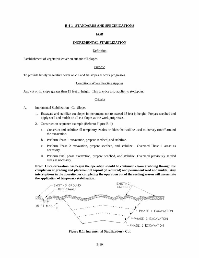
B.10
B-4-1 STANDARDS AND SPECIFICATIONS
FOR
INCREMENTAL STABILIZATION
Definition
Establishment of vegetative cover on cut and fill slopes.
Purpose To provide timely vegetative cover on cut and fill slopes as work progresses.
Conditions Where Practice Applies
Any cut or fill slope greater than 15 feet in height. This practice also applies to stockpiles.
Criteria
A. Incremental Stabilization - Cut Slopes
1. Excavate and stabilize cut slopes in increments not to exceed 15 feet in height. Prepare seedbed and apply seed and mulch on all cut slopes as the work progresses.
2. Construction sequence example (Refer to Figure B.1):
a. Construct and stabilize all temporary swales or dikes that will be used to convey runoff around the excavation.
b. Perform Phase 1 excavation, prepare seedbed, and stabilize.
c. Perform Phase 2 excavation, prepare seedbed, and stabilize. Overseed Phase 1 areas as necessary.
d. Perform final phase excavation, prepare seedbed, and stabilize. Overseed previously seeded areas as necessary.
Note: Once excavation has begun the operation should be continuous from grubbing through the completion of grading and placement of topsoil (if required) and permanent seed and mulch. Any interruptions in the operation or completing the operation out of the seeding season will necessitate the application of temporary stabilization.
Figure B.1: Incremental Stabilization – Cut
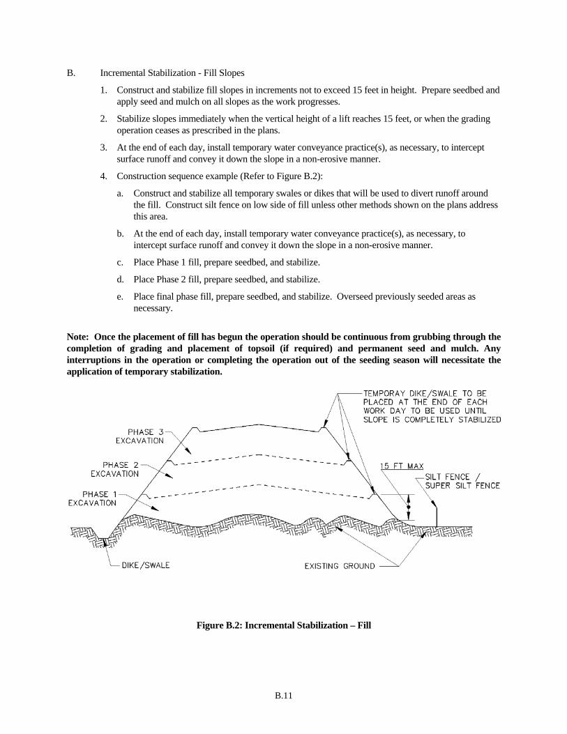
B.11
B. Incremental Stabilization - Fill Slopes
1. Construct and stabilize fill slopes in increments not to exceed 15 feet in height. Prepare seedbed and apply seed and mulch on all slopes as the work progresses.
2. Stabilize slopes immediately when the vertical height of a lift reaches 15 feet, or when the grading operation ceases as prescribed in the plans.
3. At the end of each day, install temporary water conveyance practice(s), as necessary, to intercept surface runoff and convey it down the slope in a non-erosive manner.
4. Construction sequence example (Refer to Figure B.2):
a. Construct and stabilize all temporary swales or dikes that will be used to divert runoff around the fill. Construct silt fence on low side of fill unless other methods shown on the plans address this area.
b. At the end of each day, install temporary water conveyance practice(s), as necessary, to intercept surface runoff and convey it down the slope in a non-erosive manner.
c. Place Phase 1 fill, prepare seedbed, and stabilize.
d. Place Phase 2 fill, prepare seedbed, and stabilize.
e. Place final phase fill, prepare seedbed, and stabilize. Overseed previously seeded areas as necessary.
Note: Once the placement of fill has begun the operation should be continuous from grubbing through the completion of grading and placement of topsoil (if required) and permanent seed and mulch. Any interruptions in the operation or completing the operation out of the seeding season will necessitate the application of temporary stabilization.
Figure B.2: Incremental Stabilization – Fill

B.12
B-4-2 STANDARDS AND SPECIFICATIONS
FOR
SOIL PREPARATION, TOPSOILING, AND SOIL AMENDMENTS
Definition
The process of preparing the soils to sustain adequate vegetative stabilization.
Purpose To provide a suitable soil medium for vegetative growth.
Conditions Where Practice Applies Where vegetative stabilization is to be established.
Criteria A. Soil Preparation
1. Temporary Stabilization
a. Seedbed preparation consists of loosening soil to a depth of 3 to 5 inches by means of suitable agricultural or construction equipment, such as disc harrows or chisel plows or rippers mounted on construction equipment. After the soil is loosened, it must not be rolled or dragged smooth but left in the roughened condition. Slopes 3:1 or flatter are to be tracked with ridges running parallel to the contour of the slope.
b. Apply fertilizer and lime as prescribed on the plans.
c. Incorporate lime and fertilizer into the top 3 to 5 inches of soil by disking or other suitable means.
2. Permanent Stabilization
a. A soil test is required for any earth disturbance of 5 acres or more. The minimum soil conditions required for permanent vegetative establishment are:
i. Soil pH between 6.0 and 7.0.
ii. Soluble salts less than 500 parts per million (ppm).
iii. Soil contains less than 40 percent clay but enough fine grained material (greater than 30 percent silt plus clay) to provide the capacity to hold a moderate amount of moisture. An exception: if lovegrass will be planted, then a sandy soil (less than 30 percent silt plus clay) would be acceptable.
iv. Soil contains 1.5 percent minimum organic matter by weight.
v. Soil contains sufficient pore space to permit adequate root penetration.
b. Application of amendments or topsoil is required if on-site soils do not meet the above conditions.
c. Graded areas must be maintained in a true and even grade as specified on the approved plan, then scarified or otherwise loosened to a depth of 3 to 5 inches.
B.13
d. Apply soil amendments as specified on the approved plan or as indicated by the results of a soil test.
e. Mix soil amendments into the top 3 to 5 inches of soil by disking or other suitable means. Rake lawn areas to smooth the surface, remove large objects like stones and branches, and ready the area for seed application. Loosen surface soil by dragging with a heavy chain or other equipment to roughen the surface where site conditions will not permit normal seedbed preparation. Track slopes 3:1 or flatter with tracked equipment leaving the soil in an irregular condition with ridges running parallel to the contour of the slope. Leave the top 1 to 3 inches of soil loose and friable. Seedbed loosening may be unnecessary on newly disturbed areas.
B. Topsoiling
1. Topsoil is placed over prepared subsoil prior to establishment of permanent vegetation. The purpose is to provide a suitable soil medium for vegetative growth. Soils of concern have low moisture content, low nutrient levels, low pH, materials toxic to plants, and/or unacceptable soil gradation.
2. Topsoil salvaged from an existing site may be used provided it meets the standards as set forth in these specifications. Typically, the depth of topsoil to be salvaged for a given soil type can be found in the representative soil profile section in the Soil Survey published by USDA-NRCS.
3. Topsoiling is limited to areas having 2:1 or flatter slopes where:
a. The texture of the exposed subsoil/parent material is not adequate to produce vegetative growth.
b. The soil material is so shallow that the rooting zone is not deep enough to support plants or furnish continuing supplies of moisture and plant nutrients.
c. The original soil to be vegetated contains material toxic to plant growth.
d. The soil is so acidic that treatment with limestone is not feasible.
4. Areas having slopes steeper than 2:1 require special consideration and design.
5. Topsoil Specifications: Soil to be used as topsoil must meet the following criteria:
a. Topsoil must be a loam, sandy loam, clay loam, silt loam, sandy clay loam, or loamy sand. Other soils may be used if recommended by an agronomist or soil scientist and approved by the appropriate approval authority. Topsoil must not be a mixture of contrasting textured subsoils and must contain less than 5 percent by volume of cinders, stones, slag, coarse fragments, gravel, sticks, roots, trash, or other materials larger than 1½ inches in diameter.
b. Topsoil must be free of noxious plants or plant parts such as Bermuda grass, quack grass, Johnson grass, nut sedge, poison ivy, thistle, or others as specified.
c. Topsoil substitutes or amendments, as recommended by a qualified agronomist or soil scientist and approved by the appropriate approval authority, may be used in lieu of natural topsoil.
6. Topsoil Application
a. Erosion and sediment control practices must be maintained when applying topsoil.
b. Uniformly distribute topsoil in a 5 to 8 inch layer and lightly compact to a minimum thickness of 4 inches. Spreading is to be performed in such a manner that sodding or seeding can proceed with a minimum of additional soil preparation and tillage. Any irregularities in the surface resulting from topsoiling or other operations must be corrected in order to prevent the formation of depressions or water pockets.
c. Topsoil must not be placed if the topsoil or subsoil is in a frozen or muddy condition, when the subsoil is excessively wet or in a condition that may otherwise be detrimental to proper grading
B.14
and seedbed preparation.
C. Soil Amendments (Fertilizer and Lime Specifications)
1. Soil tests must be performed to determine the exact ratios and application rates for both lime and fertilizer on sites having disturbed areas of 5 acres or more. Soil analysis may be performed by a recognized private or commercial laboratory. Soil samples taken for engineering purposes may also be used for chemical analyses.
2. Fertilizers must be uniform in composition, free flowing and suitable for accurate application by appropriate equipment. Manure may be substituted for fertilizer with prior approval from the appropriate approval authority. Fertilizers must all be delivered to the site fully labeled according to the applicable laws and must bear the name, trade name or trademark and warranty of the producer.
3. Lime materials must be ground limestone (hydrated or burnt lime may be substituted except when hydroseeding) which contains at least 50 percent total oxides (calcium oxide plus magnesium oxide). Limestone must be ground to such fineness that at least 50 percent will pass through a #100 mesh sieve and 98 to 100 percent will pass through a #20 mesh sieve.
4. Lime and fertilizer are to be evenly distributed and incorporated into the top 3 to 5 inches of soil by disking or other suitable means.
5. Where the subsoil is either highly acidic or composed of heavy clays, spread ground limestone at the rate of 4 to 8 tons/acre (200-400 pounds per 1,000 square feet) prior to the placement of topsoil.
B.15
B-4-3 STANDARDS AND SPECIFICATIONS
FOR
SEEDING AND MULCHING
Definition
The application of seed and mulch to establish vegetative cover.
Purpose To protect disturbed soils from erosion during and at the end of construction.
Conditions Where Practice Applies To the surface of all perimeter controls, slopes, and any disturbed area not under active grading.
Criteria
A. Seeding
1. Specifications
a. All seed must meet the requirements of the Maryland State Seed Law. All seed must be subject to re-testing by a recognized seed laboratory. All seed used must have been tested within the 6 months immediately preceding the date of sowing such material on any project. Refer to Table B.4 regarding the quality of seed. Seed tags must be available upon request to the inspector to verify type of seed and seeding rate.
b. Mulch alone may be applied between the fall and spring seeding dates only if the ground is frozen. The appropriate seeding mixture must be applied when the ground thaws.
c. Inoculants: The inoculant for treating legume seed in the seed mixtures must be a pure culture of nitrogen fixing bacteria prepared specifically for the species. Inoculants must not be used later than the date indicated on the container. Add fresh inoculants as directed on the package. Use four times the recommended rate when hydroseeding. Note: It is very important to keep inoculant as cool as possible until used. Temperatures above 75 to 80 degrees Fahrenheit can weaken bacteria and make the inoculant less effective.
d. Sod or seed must not be placed on soil which has been treated with soil sterilants or chemicals used for weed control until sufficient time has elapsed (14 days min.) to permit dissipation of phyto-toxic materials.
2. Application
a. Dry Seeding: This includes use of conventional drop or broadcast spreaders.
i. Incorporate seed into the subsoil at the rates prescribed on Temporary Seeding Table B.1, Permanent Seeding Table B.3, or site-specific seeding summaries.
ii. Apply seed in two directions, perpendicular to each other. Apply half the seeding rate in each direction. Roll the seeded area with a weighted roller to provide good seed to soil contact.

B.16
b. Drill or Cultipacker Seeding: Mechanized seeders that apply and cover seed with soil.
i. Cultipacking seeders are required to bury the seed in such a fashion as to provide at least 1/4 inch of soil covering. Seedbed must be firm after planting.
ii. Apply seed in two directions, perpendicular to each other. Apply half the seeding rate in each direction.
c. Hydroseeding: Apply seed uniformly with hydroseeder (slurry includes seed and fertilizer).
i. If fertilizer is being applied at the time of seeding, the application rates should not exceed the following: nitrogen, 100 pounds per acre total of soluble nitrogen; P2O5 (phosphorous), 200 pounds per acre; K2O (potassium), 200 pounds per acre.
ii. Lime: Use only ground agricultural limestone (up to 3 tons per acre may be applied by hydroseeding). Normally, not more than 2 tons are applied by hydroseeding at any one time. Do not use burnt or hydrated lime when hydroseeding.
iii. Mix seed and fertilizer on site and seed immediately and without interruption.
iv. When hydroseeding do not incorporate seed into the soil.
B. Mulching
1. Mulch Materials (in order of preference)
a. Straw consisting of thoroughly threshed wheat, rye, oat, or barley and reasonably bright in color. Straw is to be free of noxious weed seeds as specified in the Maryland Seed Law and not musty, moldy, caked, decayed, or excessively dusty. Note: Use only sterile straw mulch in areas where one species of grass is desired.
b. Wood Cellulose Fiber Mulch (WCFM) consisting of specially prepared wood cellulose processed into a uniform fibrous physical state.
i. WCFM is to be dyed green or contain a green dye in the package that will provide an appropriate color to facilitate visual inspection of the uniformly spread slurry.
ii. WCFM, including dye, must contain no germination or growth inhibiting factors.
iii. WCFM materials are to be manufactured and processed in such a manner that the wood cellulose fiber mulch will remain in uniform suspension in water under agitation and will blend with seed, fertilizer and other additives to form a homogeneous slurry. The mulch material must form a blotter-like ground cover, on application, having moisture absorption and percolation properties and must cover and hold grass seed in contact with the soil without inhibiting the growth of the grass seedlings.
iv. WCFM material must not contain elements or compounds at concentration levels that will be phyto-toxic.
v. WCFM must conform to the following physical requirements: fiber length of approximately 10 millimeters, diameter approximately 1 millimeter, pH range of 4.0 to 8.5, ash content of 1.6 percent maximum and water holding capacity of 90 percent minimum.

B.17
2. Application
a. Apply mulch to all seeded areas immediately after seeding.
b. When straw mulch is used, spread it over all seeded areas at the rate of 2 tons per acre to a uniform loose depth of 1 to 2 inches. Apply mulch to achieve a uniform distribution and depth so that the soil surface is not exposed. When using a mulch anchoring tool, increase the application rate to 2.5 tons per acre.
c. Wood cellulose fiber used as mulch must be applied at a net dry weight of 1500 pounds per acre. Mix the wood cellulose fiber with water to attain a mixture with a maximum of 50 pounds of wood cellulose fiber per 100 gallons of water.
3. Anchoring
a. Perform mulch anchoring immediately following application of mulch to minimize loss by wind or water. This may be done by one of the following methods (listed by preference), depending upon the size of the area and erosion hazard:
i. A mulch anchoring tool is a tractor drawn implement designed to punch and anchor mulch into the soil surface a minimum of 2 inches. This practice is most effective on large areas, but is limited to flatter slopes where equipment can operate safely. If used on sloping land, this practice should follow the contour.
ii. Wood cellulose fiber may be used for anchoring straw. Apply the fiber binder at a net dry weight of 750 pounds per acre. Mix the wood cellulose fiber with water at a maximum of 50 pounds of wood cellulose fiber per 100 gallons of water.
iii. Synthetic binders such as Acrylic DLR (Agro-Tack), DCA-70, Petroset, Terra Tax II, Terra Tack AR or other approved equal may be used. Follow application rates as specified by the manufacturer. Application of liquid binders needs to be heavier at the edges where wind catches mulch, such as in valleys and on crests of banks. Use of asphalt binders is strictly prohibited.
iv. Lightweight plastic netting may be stapled over the mulch according to manufacturer recommendations. Netting is usually available in rolls 4 to 15 feet wide and 300 to 3,000 feet long.
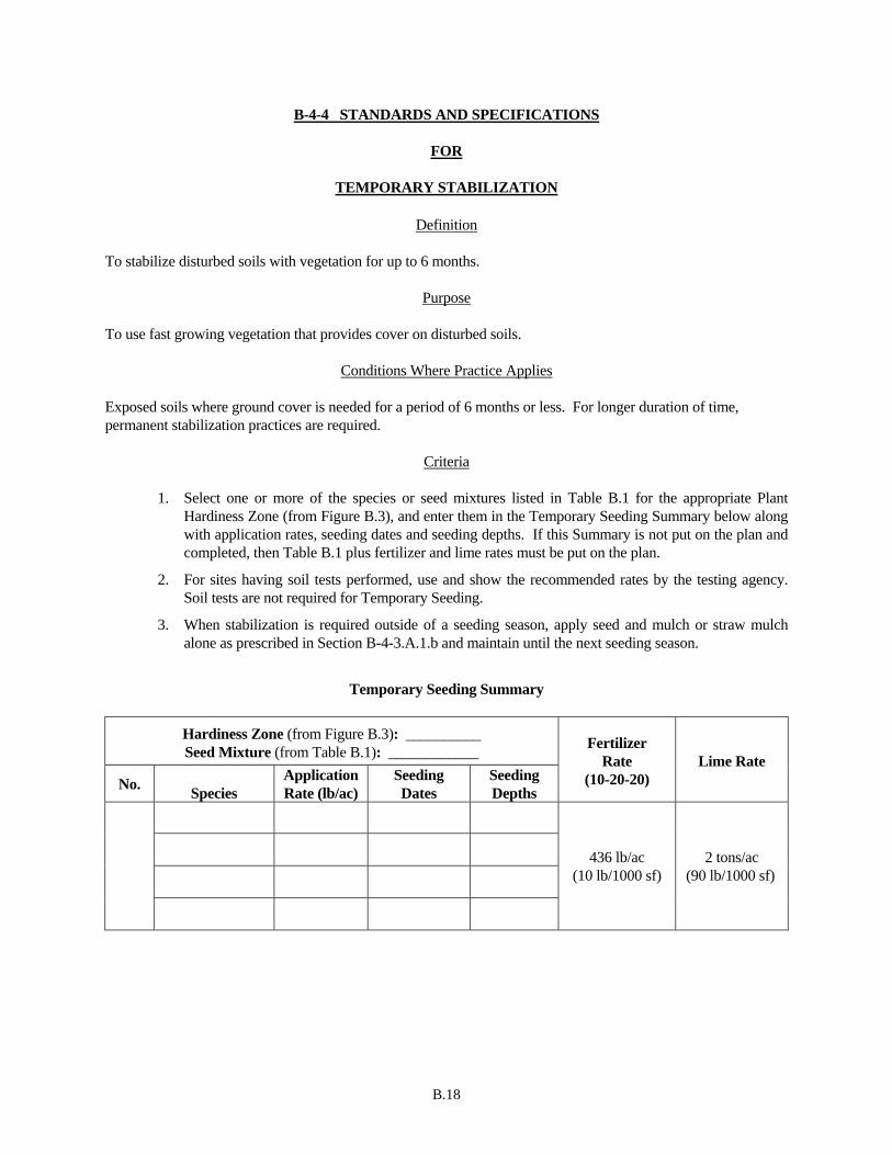
B.18
B-4-4 STANDARDS AND SPECIFICATIONS
FOR
TEMPORARY STABILIZATION
Definition
To stabilize disturbed soils with vegetation for up to 6 months.
Purpose To use fast growing vegetation that provides cover on disturbed soils.
Conditions Where Practice Applies Exposed soils where ground cover is needed for a period of 6 months or less. For longer duration of time, permanent stabilization practices are required.
Criteria
1. Select one or more of the species or seed mixtures listed in Table B.1 for the appropriate Plant Hardiness Zone (from Figure B.3), and enter them in the Temporary Seeding Summary below along with application rates, seeding dates and seeding depths. If this Summary is not put on the plan and completed, then Table B.1 plus fertilizer and lime rates must be put on the plan.
2. For sites having soil tests performed, use and show the recommended rates by the testing agency. Soil tests are not required for Temporary Seeding.
3. When stabilization is required outside of a seeding season, apply seed and mulch or straw mulch alone as prescribed in Section B-4-3.A.1.b and maintain until the next seeding season.
Temporary Seeding Summary
Hardiness Zone (from Figure B.3): __________ Seed Mixture (from Table B.1): ____________
No. Species
Application Rate (lb/ac)
Seeding Dates
Seeding Depths
Fertilizer Rate
(10-20-20) Lime Rate
436 lb/ac (10 lb/1000 sf)
2 tons/ac (90 lb/1000 sf)
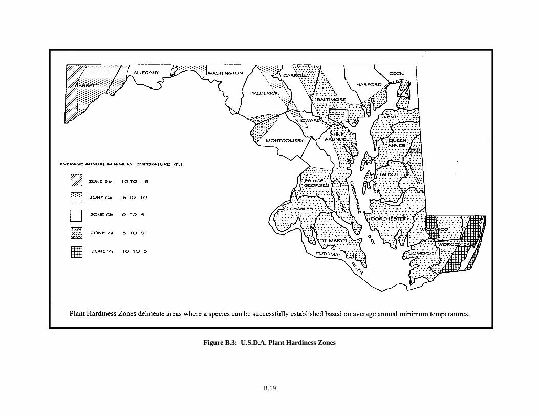
B.19
Figure B.3: U.S.D.A. Plant Hardiness Zones

B.20
Table B.1: Temporary Seeding for Site Stabilization
NOTES: 1/ Seeding rates for the warm-season grasses are in pounds of Pure Live Seed (PLS). Actual planting rates shall be adjusted to reflect percent seed germination and purity, as
tested. Adjustments are usually not needed for the cool-season grasses. Seeding rates listed above are for temporary seedings, when planted alone. When planted as a nurse crop with permanent seed mixes, use 1/3 of the seeding rate listed above for barley, oats, and wheat. For smaller-seeded grasses (annual ryegrass, pearl millet, foxtail millet), do not exceed more than 5% (by weight) of the overall permanent seeding mix. Cereal rye generally should not be used as a nurse crop, unless planting will occur in very late fall beyond the seeding dates for other temporary seedings. Cereal rye has allelopathic properties that inhibit the germination and growth of other plants. If it must be used as a nurse crop, seed at 1/3 of the rate listed above. Oats are the recommended nurse crop for warm-season grasses.
2/ For sandy soils, plant seeds at twice the depth listed above. 3/ The planting dates listed are averages for each Zone and may require adjustment to reflect local conditions, especially near the boundaries of the zone.
Seeding Rate 1/ Recommended Seeding Dates by Plant Hardiness Zone 3/ Plant Species
lb/ac lb/1000 ft2
Seeding Depth 2/ (inches) 5b and 6a 6b 7a and 7b
Cool-Season Grasses Annual Ryegrass (Lolium perenne ssp. multiflorum) 40 1.0 0.5 Mar 15 to May 31; Aug 1 to Sep 30 Mar 1 to May 15; Aug
1 to Oct 15 Feb 15 to Apr 30; Aug 15 to Nov 30
Barley (Hordeum vulgare) 96 2.2 1.0 Mar 15 to May 31; Aug 1 to Sep 30 Mar 1 to May 15; Aug 1 to Oct 15
Feb 15 to Apr 30; Aug 15 to Nov 30
Oats (Avena sativa) 72 1.7 1.0 Mar 15 to May 31; Aug 1 to Sep 30 Mar 1 to May 15; Aug 1 to Oct 15
Feb 15 to Apr 30; Aug 15 to Nov 30
Wheat (Triticum aestivum) 120 2.8 1.0 Mar 15 to May 31; Aug 1 to Sep 30 Mar 1 to May 15; Aug 1 to Oct 15
Feb 15 to Apr 30; Aug 15 to Nov 30
Cereal Rye (Secale cereale) 112 2.8 1.0 Mar 15 to May 31; Aug 1 to Oct 31 Mar 1 to May 15; Aug 1 to Nov 15
Feb 15 to Apr 30; Aug 15 to Dec 15
Warm-Season Grasses
Foxtail Millet (Setaria italica) 30 0.7 0.5 Jun 1 to Jul 31 May 16 to Jul 31 May 1 to Aug 14
Pearl Millet (Pennisetum glaucum) 20 0.5 0.5 Jun 1 to Jul 31 May 16 to Jul 31 May 1 to Aug 14

B.21
B-4-5 STANDARDS AND SPECIFICATIONS
FOR
PERMANENT STABILIZATION
Definition
To stabilize disturbed soils with permanent vegetation.
Purpose To use long-lived perennial grasses and legumes to establish permanent ground cover on disturbed soils.
Conditions Where Practice Applies
Exposed soils where ground cover is needed for 6 months or more.
Criteria
A. Seed Mixtures
1. General Use
a. Select one or more of the species or mixtures listed in Table B.3 for the appropriate Plant Hardiness Zone (from Figure B.3) and based on the site condition or purpose found on Table B.2. Enter selected mixture(s), application rates, and seeding dates in the Permanent Seeding Summary. The Summary is to be placed on the plan.
b. Additional planting specifications for exceptional sites such as shorelines, stream banks, or dunes or for special purposes such as wildlife or aesthetic treatment may be found in USDA-NRCS Technical Field Office Guide, Section 342 - Critical Area Planting.
c. For sites having disturbed area over 5 acres, use and show the rates recommended by the soil testing agency.
d. For areas receiving low maintenance, apply urea form fertilizer (46-0-0) at 3 ½ pounds per 1000 square feet (150 pounds per acre) at the time of seeding in addition to the soil amendments shown in the Permanent Seeding Summary .
2. Turfgrass Mixtures
a. Areas where turfgrass may be desired include lawns, parks, playgrounds, and commercial sites which will receive a medium to high level of maintenance.
b. Select one or more of the species or mixtures listed below based on the site conditions or purpose. Enter selected mixture(s), application rates, and seeding dates in the Permanent Seeding Summary. The summary is to be placed on the plan.
i. Kentucky Bluegrass: Full Sun Mixture: For use in areas that receive intensive management. Irrigation required in the areas of central Maryland and Eastern Shore. Recommended Certified Kentucky Bluegrass Cultivars Seeding Rate: 1.5 to 2.0 pounds per 1000 square feet. Choose a minimum of three Kentucky bluegrass cultivars with each ranging from 10 to 35 percent of the total mixture by weight.
ii. Kentucky Bluegrass/Perennial Rye: Full Sun Mixture: For use in full sun areas where

B.22
rapid establishment is necessary and when turf will receive medium to intensive management. Certified Perennial Ryegrass Cultivars/Certified Kentucky Bluegrass Seeding Rate: 2 pounds mixture per 1000 square feet. Choose a minimum of three Kentucky bluegrass cultivars with each ranging from 10 to 35 percent of the total mixture by weight.
iii. Tall Fescue/Kentucky Bluegrass: Full Sun Mixture: For use in drought prone areas and/or for areas receiving low to medium management in full sun to medium shade. Recommended mixture includes; Certified Tall Fescue Cultivars 95 to 100 percent, Certified Kentucky Bluegrass Cultivars 0 to 5 percent. Seeding Rate: 5 to 8 pounds per 1000 square feet. One or more cultivars may be blended.
iv. Kentucky Bluegrass/Fine Fescue: Shade Mixture: For use in areas with shade in Bluegrass lawns. For establishment in high quality, intensively managed turf area. Mixture includes; Certified Kentucky Bluegrass Cultivars 30 to 40 percent and Certified Fine Fescue and 60 to 70 percent. Seeding Rate: 1½ to 3 pounds per 1000 square feet.
Notes: Select turfgrass varieties from those listed in the most current University of Maryland Publication, Agronomy Memo #77, "Turfgrass Cultivar Recommendations for Maryland"
Choose certified material. Certified material is the best guarantee of cultivar purity. The certification program of the Maryland Department of Agriculture, Turf and Seed Section, provides a reliable means of consumer protection and assures a pure genetic line
c. Ideal Times of Seeding for Turf Grass Mixtures
Western MD: March 15 to June 1, August 1 to October 1 (Hardiness Zones: 5b, 6a) Central MD: March 1 to May 15, August 15 to October 15 (Hardiness Zone: 6b) Southern MD, Eastern Shore: March 1 to May 15, August 15 to October 15
(Hardiness Zones: 7a, 7b) d. Till areas to receive seed by disking or other approved methods to a depth of 2 to 4 inches, level
and rake the areas to prepare a proper seedbed. Remove stones and debris over 1½ inches in diameter. The resulting seedbed must be in such condition that future mowing of grasses will pose no difficulty.
e. If soil moisture is deficient, supply new seedings with adequate water for plant growth (½ to 1 inch every 3 to 4 days depending on soil texture) until they are firmly established. This is especially true when seedings are made late in the planting season, in abnormally dry or hot seasons, or on adverse sites.
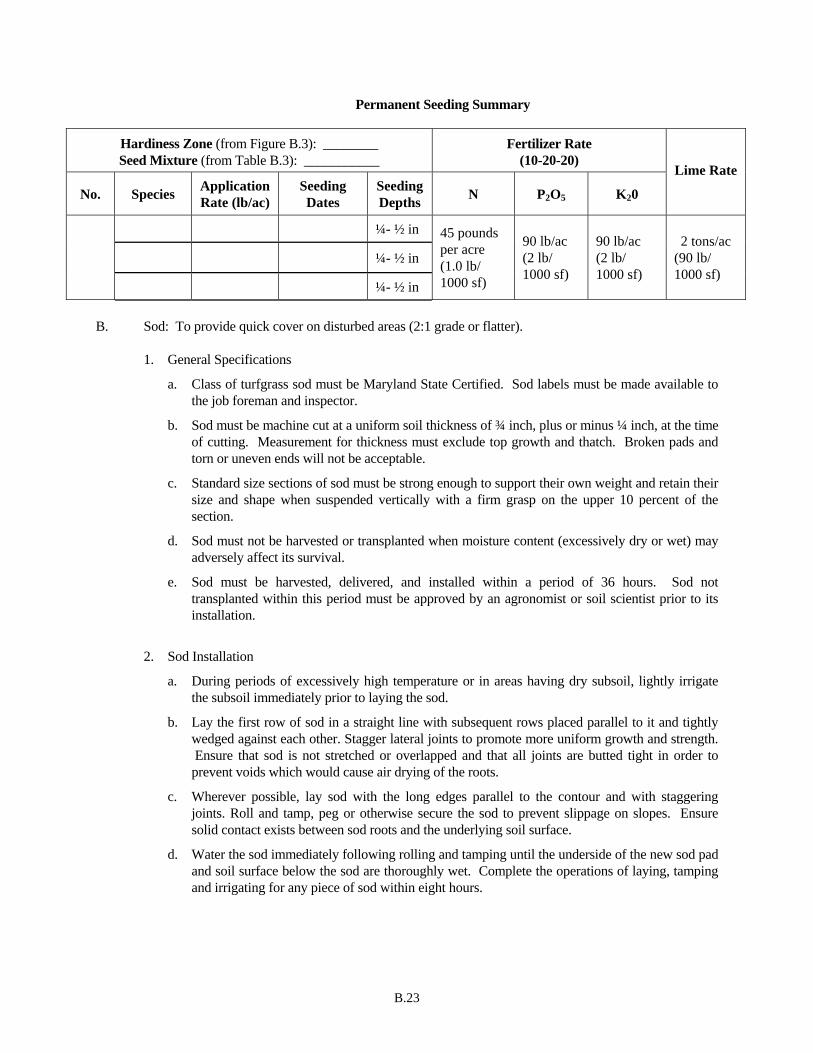
B.23
Permanent Seeding Summary
Hardiness Zone (from Figure B.3): ________ Seed Mixture (from Table B.3): ___________
Fertilizer Rate (10-20-20)
No. Species Application Rate (lb/ac)
Seeding Dates
Seeding Depths N P2O5 K20
Lime Rate
¼- ½ in
¼- ½ in
¼- ½ in
45 pounds per acre (1.0 lb/ 1000 sf)
90 lb/ac (2 lb/ 1000 sf)
90 lb/ac (2 lb/ 1000 sf)
2 tons/ac (90 lb/ 1000 sf)
B. Sod: To provide quick cover on disturbed areas (2:1 grade or flatter).
1. General Specifications
a. Class of turfgrass sod must be Maryland State Certified. Sod labels must be made available to the job foreman and inspector.
b. Sod must be machine cut at a uniform soil thickness of ¾ inch, plus or minus ¼ inch, at the time of cutting. Measurement for thickness must exclude top growth and thatch. Broken pads and torn or uneven ends will not be acceptable.
c. Standard size sections of sod must be strong enough to support their own weight and retain their size and shape when suspended vertically with a firm grasp on the upper 10 percent of the section.
d. Sod must not be harvested or transplanted when moisture content (excessively dry or wet) may adversely affect its survival.
e. Sod must be harvested, delivered, and installed within a period of 36 hours. Sod not transplanted within this period must be approved by an agronomist or soil scientist prior to its installation.
2. Sod Installation
a. During periods of excessively high temperature or in areas having dry subsoil, lightly irrigate the subsoil immediately prior to laying the sod.
b. Lay the first row of sod in a straight line with subsequent rows placed parallel to it and tightly wedged against each other. Stagger lateral joints to promote more uniform growth and strength. Ensure that sod is not stretched or overlapped and that all joints are butted tight in order to prevent voids which would cause air drying of the roots.
c. Wherever possible, lay sod with the long edges parallel to the contour and with staggering joints. Roll and tamp, peg or otherwise secure the sod to prevent slippage on slopes. Ensure solid contact exists between sod roots and the underlying soil surface.
d. Water the sod immediately following rolling and tamping until the underside of the new sod pad and soil surface below the sod are thoroughly wet. Complete the operations of laying, tamping and irrigating for any piece of sod within eight hours.
B.24
3. Sod Maintenance
a. In the absence of adequate rainfall, water daily during the first week or as often and sufficiently as necessary to maintain moist soil to a depth of 4 inches. Water sod during the heat of the day to prevent wilting.
b. After the first week, sod watering is required as necessary to maintain adequate moisture content.
c. Do not mow until the sod is firmly rooted. No more than ⅓ of the grass leaf must be removed by the initial cutting or subsequent cuttings. Maintain a grass height of at least 3 inches unless otherwise specified.
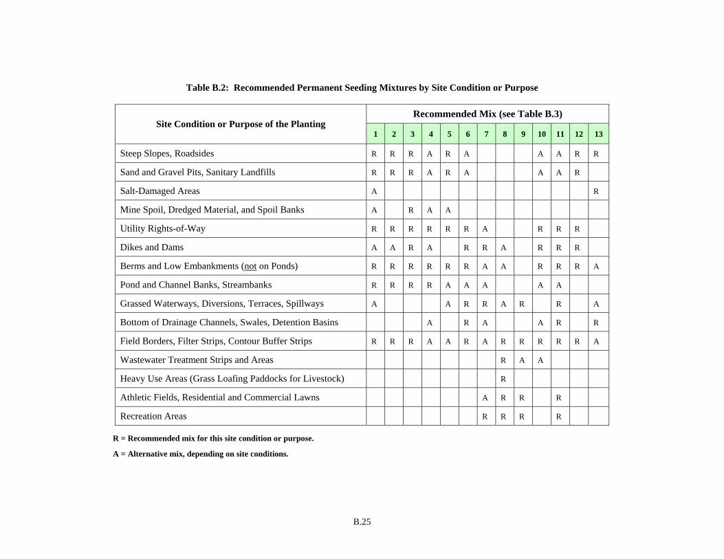
B.25
Table B.2: Recommended Permanent Seeding Mixtures by Site Condition or Purpose
Recommended Mix (see Table B.3) Site Condition or Purpose of the Planting
1 2 3 4 5 6 7 8 9 10 11 12 13
Steep Slopes, Roadsides R R R A R A A A R R
Sand and Gravel Pits, Sanitary Landfills R R R A R A A A R
Salt-Damaged Areas A R
Mine Spoil, Dredged Material, and Spoil Banks A R A A
Utility Rights-of-Way R R R R R R A R R R
Dikes and Dams A A R A R R A R R R
Berms and Low Embankments (not on Ponds) R R R R R R A A R R R A
Pond and Channel Banks, Streambanks R R R R A A A A A
Grassed Waterways, Diversions, Terraces, Spillways A A R R A R R A
Bottom of Drainage Channels, Swales, Detention Basins A R A A R R
Field Borders, Filter Strips, Contour Buffer Strips R R R A A R A R R R R R A
Wastewater Treatment Strips and Areas R A A
Heavy Use Areas (Grass Loafing Paddocks for Livestock) R
Athletic Fields, Residential and Commercial Lawns A R R R
Recreation Areas R R R R
R = Recommended mix for this site condition or purpose.
A = Alternative mix, depending on site conditions.
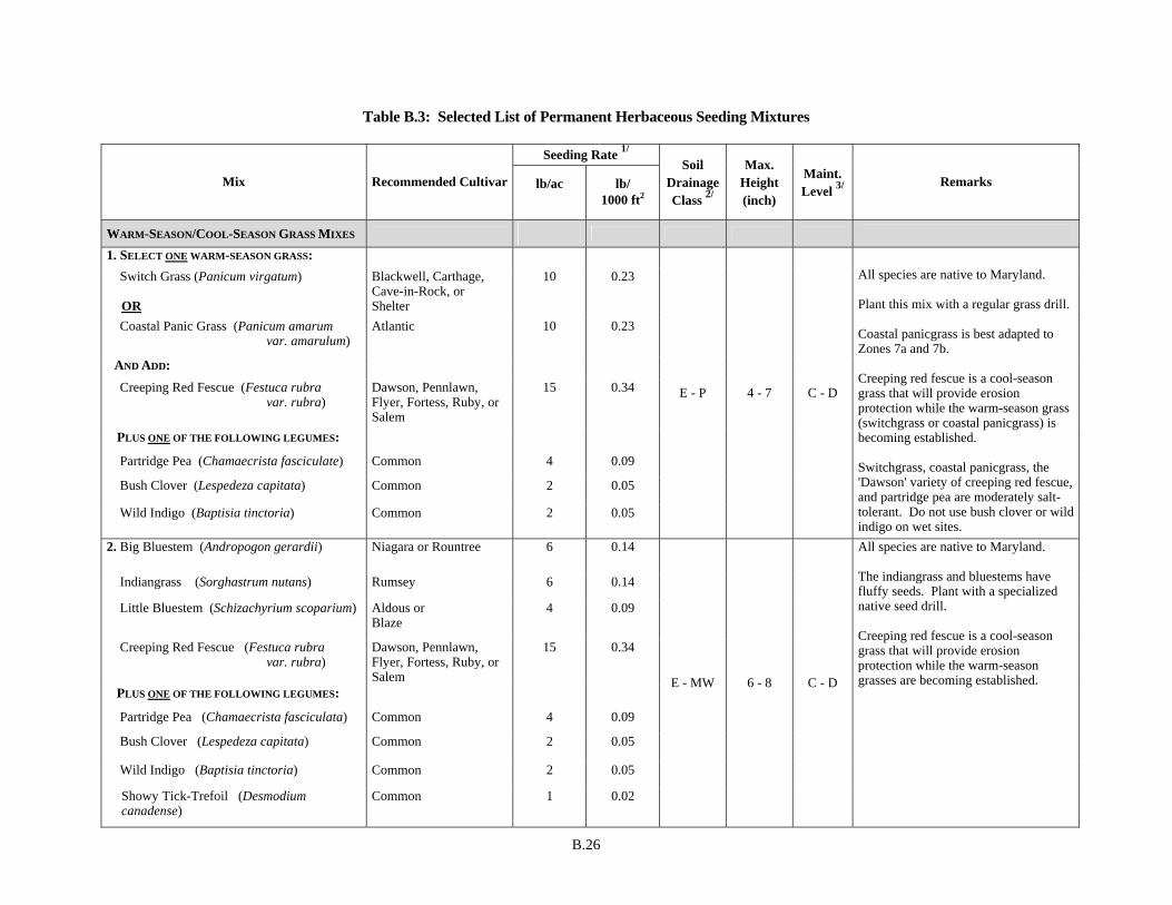
B.26
Table B.3: Selected List of Permanent Herbaceous Seeding Mixtures
Seeding Rate 1/
Mix Recommended Cultivar lb/ac lb/ 1000 ft2
Soil Drainage Class 2/
Max. Height (inch)
Maint. Level 3/
Remarks
WARM-SEASON/COOL-SEASON GRASS MIXES
1. SELECT ONE WARM-SEASON GRASS: Switch Grass (Panicum virgatum)
OR
Blackwell, Carthage, Cave-in-Rock, or Shelter
10 0.23
Coastal Panic Grass (Panicum amarum var. amarulum)
Atlantic 10 0.23
AND ADD:
Creeping Red Fescue (Festuca rubra var. rubra)
Dawson, Pennlawn, Flyer, Fortess, Ruby, or Salem
15 0.34
PLUS ONE OF THE FOLLOWING LEGUMES:
Partridge Pea (Chamaecrista fasciculate)
Common
4
0.09
Bush Clover (Lespedeza capitata) Common 2 0.05
Wild Indigo (Baptisia tinctoria) Common 2 0.05
E - P 4 - 7 C - D
All species are native to Maryland. Plant this mix with a regular grass drill. Coastal panicgrass is best adapted to Zones 7a and 7b. Creeping red fescue is a cool-season grass that will provide erosion protection while the warm-season grass (switchgrass or coastal panicgrass) is becoming established. Switchgrass, coastal panicgrass, the 'Dawson' variety of creeping red fescue, and partridge pea are moderately salt-tolerant. Do not use bush clover or wild indigo on wet sites.
2. Big Bluestem (Andropogon gerardii) Niagara or Rountree 6 0.14
Indiangrass (Sorghastrum nutans) Rumsey 6 0.14
Little Bluestem (Schizachyrium scoparium) Aldous or Blaze
4 0.09
Creeping Red Fescue (Festuca rubra var. rubra)
Dawson, Pennlawn, Flyer, Fortess, Ruby, or Salem
15 0.34
PLUS ONE OF THE FOLLOWING LEGUMES:
Partridge Pea (Chamaecrista fasciculata)
Common
4
0.09
Bush Clover (Lespedeza capitata) Common 2 0.05
Wild Indigo (Baptisia tinctoria) Common 2 0.05
Showy Tick-Trefoil (Desmodium canadense)
Common 1 0.02
E - MW 6 - 8 C - D
All species are native to Maryland. The indiangrass and bluestems have fluffy seeds. Plant with a specialized native seed drill. Creeping red fescue is a cool-season grass that will provide erosion protection while the warm-season grasses are becoming established.

B.27
Seeding Rate 1/
Mix Recommended Cultivar lb/ac lb/ 1000 ft2
Soil Drainage Class 2/
Max. Height (inch)
Maint. Level 3/
Remarks
WARM-SEASON/COOL-SEASON GRASS MIXES
3. SELECT THREE GRASSES:
Deertongue (Dichanthelium clandestinum) Tioga 20 0.46
Sheep Fescue (Festuca ovina)
OR
Common or Bighorn 20 0.46
Canada Wild Rye (Elymus canadensis) Common 3 0.07
Redtop (Agrostis gigantean) Streaker 1 0.02
PLUS ONE OF THE FOLLOWING LEGUMES:
Common Lespedeza (Lespedeza striata)
Kobe
10
0.23
Korean Lespedeza (Lespedeza stipulacea) Climax or Rowan 10 0.23
E - MW 4 - 6 C - D
Excellent for excessively droughty, low pH (acidic) soils. Sheep fescue, Canada wild rye, and redtop are cool-season grasses that will provide erosion protection while the warm-season grass (deertongue) is becoming established. Common lespedeza ('Kobe' variety) is more tolerant of low acidity and high manganese concentrations than Korean lespedeza. These lespedezas are reseeding annuals.
4. Deertongue (Dichanthelium clandestinum) Tioga 15 0.34
Creeping Red Fescue (Festuca rubra var. rubra)
Dawson, Pennlawn, Flyer, Fortess, Ruby, or Salem
20 0.46
Virginia Wild Rye (Elymus virginicus) OR
Common 5 0.11
Canada Wild Rye (Elymus canadensis) Common 5 0.11
W - P 2 - 3 C - D
Use Virginia wild rye on moist, shady sites. Use Canada wild rye on droughty sites.
Table B.3: Selected List of Permanent Herbaceous Seeding Mixtures (Continued)
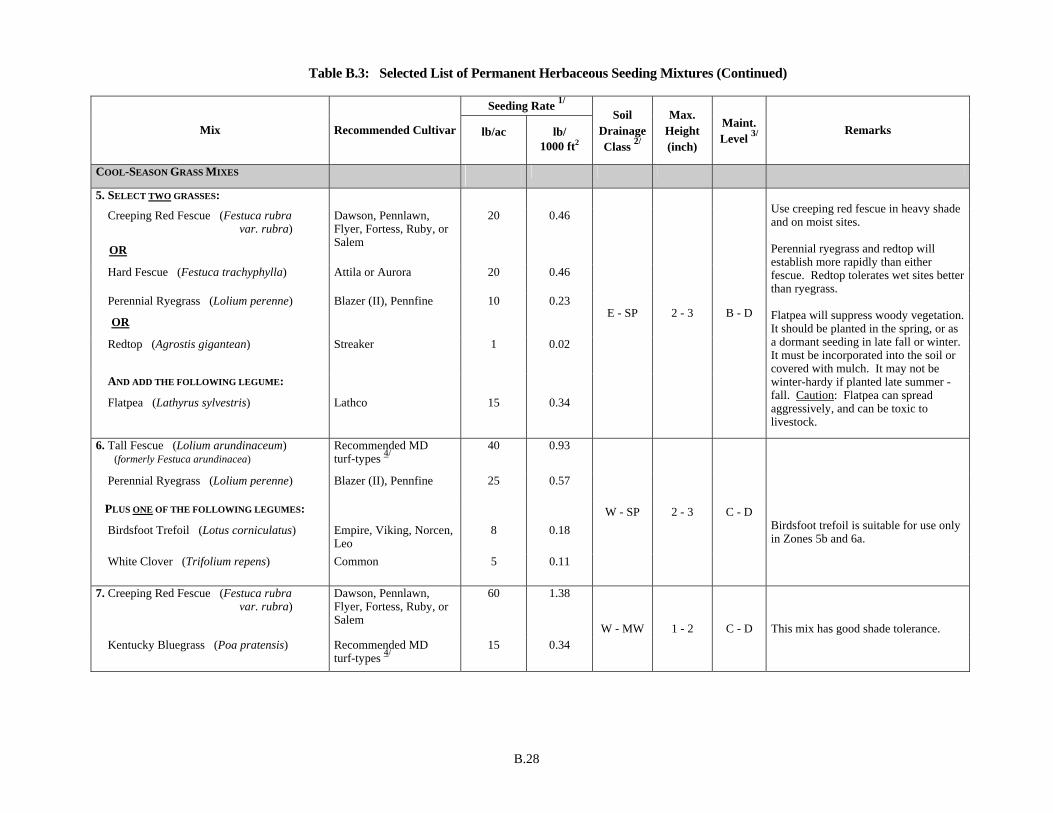
B.28
Seeding Rate 1/
Mix Recommended Cultivar lb/ac lb/ 1000 ft2
Soil Drainage Class 2/
Max. Height (inch)
Maint. Level 3/
Remarks
COOL-SEASON GRASS MIXES
5. SELECT TWO GRASSES:
Creeping Red Fescue (Festuca rubra var. rubra)
OR
Dawson, Pennlawn, Flyer, Fortess, Ruby, or Salem
20 0.46
Hard Fescue (Festuca trachyphylla) Attila or Aurora 20 0.46
Perennial Ryegrass (Lolium perenne)
OR
Blazer (II), Pennfine 10 0.23
Redtop (Agrostis gigantean) Streaker 1 0.02
AND ADD THE FOLLOWING LEGUME:
Flatpea (Lathyrus sylvestris)
Lathco
15
0.34
E - SP 2 - 3 B - D
Use creeping red fescue in heavy shade and on moist sites. Perennial ryegrass and redtop will establish more rapidly than either fescue. Redtop tolerates wet sites better than ryegrass. Flatpea will suppress woody vegetation. It should be planted in the spring, or as a dormant seeding in late fall or winter. It must be incorporated into the soil or covered with mulch. It may not be winter-hardy if planted late summer - fall. Caution: Flatpea can spread aggressively, and can be toxic to livestock.
6. Tall Fescue (Lolium arundinaceum) (formerly Festuca arundinacea)
Recommended MD turf-types 4/
40 0.93
Perennial Ryegrass (Lolium perenne) Blazer (II), Pennfine 25 0.57
PLUS ONE OF THE FOLLOWING LEGUMES:
Birdsfoot Trefoil (Lotus corniculatus)
Empire, Viking, Norcen, Leo
8
0.18
White Clover (Trifolium repens) Common 5 0.11
W - SP 2 - 3 C - D
Birdsfoot trefoil is suitable for use only in Zones 5b and 6a.
7. Creeping Red Fescue (Festuca rubra var. rubra)
Dawson, Pennlawn, Flyer, Fortess, Ruby, or Salem
60 1.38
Kentucky Bluegrass (Poa pratensis) Recommended MD turf-types 4/
15 0.34 W - MW 1 - 2 C - D This mix has good shade tolerance.
Table B.3: Selected List of Permanent Herbaceous Seeding Mixtures (Continued)
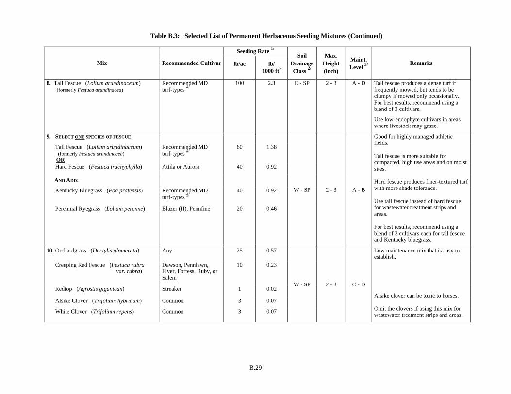
B.29
Seeding Rate 1/
Mix Recommended Cultivar lb/ac lb/ 1000 ft2
Soil Drainage Class 2/
Max. Height (inch)
Maint. Level 3/
Remarks
8. Tall Fescue (Lolium arundinaceum) (formerly Festuca arundinacea)
Recommended MD turf-types 4/
100 2.3 E - SP 2 - 3 A - D Tall fescue produces a dense turf if frequently mowed, but tends to be clumpy if mowed only occasionally. For best results, recommend using a blend of 3 cultivars.
Use low-endophyte cultivars in areas where livestock may graze.
9. SELECT ONE SPECIES OF FESCUE:
Tall Fescue (Lolium arundinaceum) (formerly Festuca arundinacea)
OR
Recommended MD turf-types 4/
60 1.38
Hard Fescue (Festuca trachyphylla) Attila or Aurora 40 0.92
AND ADD:
Kentucky Bluegrass (Poa pratensis)
Recommended MD turf-types 4/
40 0.92
Perennial Ryegrass (Lolium perenne) Blazer (II), Pennfine 20 0.46
W - SP 2 - 3 A - B
Good for highly managed athletic fields. Tall fescue is more suitable for compacted, high use areas and on moist sites. Hard fescue produces finer-textured turf with more shade tolerance. Use tall fescue instead of hard fescue for wastewater treatment strips and areas. For best results, recommend using a blend of 3 cultivars each for tall fescue and Kentucky bluegrass.
10. Orchardgrass (Dactylis glomerata) Any 25 0.57
Creeping Red Fescue (Festuca rubra var. rubra)
Dawson, Pennlawn, Flyer, Fortess, Ruby, or Salem
10 0.23
Redtop (Agrostis gigantean) Streaker 1 0.02
Alsike Clover (Trifolium hybridum) Common 3 0.07
White Clover (Trifolium repens) Common 3 0.07
W - SP 2 - 3 C - D
Low maintenance mix that is easy to establish. Alsike clover can be toxic to horses. Omit the clovers if using this mix for wastewater treatment strips and areas.
Table B.3: Selected List of Permanent Herbaceous Seeding Mixtures (Continued)

B.30
Seeding Rate 1/
Mix Recommended Cultivar lb/ac lb/ 1000 ft2
Soil Drainage Class 2/
Max. Height (inch)
Maint. Level 3/
Remarks
11. Creeping Red Fescue (Festuca rubra var. rubra)
Dawson, Pennlawn, Flyer, Fortess, Ruby, or Salem
30 0.69
Chewings Fescue (Festuca rubra ssp. commutata)
Common 30 0.69
Kentucky Bluegrass (Poa pratensis) Recommended MD turf-types 4/
20 0.46
OPTIONAL ADDITION
Rough Bluegrass (Poa trivialis)
Common
15
0.34
E - MW 2 - 3 B - D
Add rough bluegrass in moist, shady conditions.
12. Creeping Red Fescue (Festuca rubra var. rubra)
Dawson, Pennlawn, Flyer, Fortess, Ruby, or Salem
25 0.57
Hard Fescue (Festuca trachyphylla) Attila or Aurora 25 0.57
Sheep Fescue (Festuca ovina) Common or Bighorn 25 0.57
PLUS WILDFLOWER MIX:
Black-eyed Susan (Rudbeckia hirta)
Lance-leaved Coreopsis (Coreopsis lanceolata)
Purple Coneflower (Echinacea purpurea)
Partridge Pea (Chamaecrista fasciculate)
OR ADD CLOVER MIX:
White Clover (Trifolium repens)
Red Clover (Trifolium pretense)
Common
Common
Common
Common
Common
Any
2
2
2
5
3
3
0.05
0.05
0.05
0.11
0.07
0.07
E - MW 2 - 3 C - D
Attractive mix of fine fescues and wildflowers for low maintenance conditions. Once well-established, the grasses may tend to outcompete the wildflowers. Wildflowers are best established by broadcasting and cultipacking on a prepared seedbed. Drilling can be also used, but care must be taken so that seeds are not drilled too deep. Hydroseeding is not recommended for this mix if wildflowers are used. (They have very small seeds.)
Table B.3: Selected List of Permanent Herbaceous Seeding Mixtures (Continued)
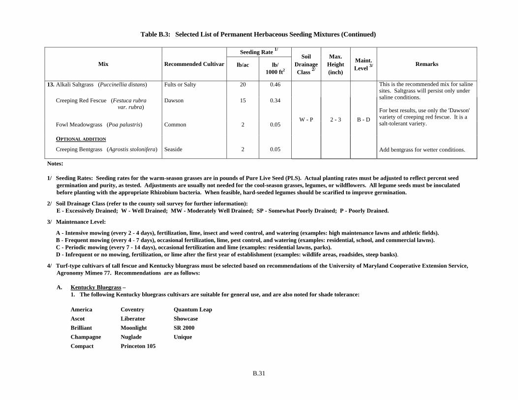
B.31
Seeding Rate 1/
Mix Recommended Cultivar lb/ac lb/ 1000 ft2
Soil Drainage Class 2/
Max. Height (inch)
Maint. Level 3/
Remarks
13. Alkali Saltgrass (Puccinellia distans) Fults or Salty 20 0.46
Creeping Red Fescue (Festuca rubra var. rubra)
Dawson 15 0.34
Fowl Meadowgrass (Poa palustris) Common 2 0.05
OPTIONAL ADDITION
Creeping Bentgrass (Agrostis stolonifera)
Seaside
2
0.05
W - P 2 - 3 B - D
This is the recommended mix for saline sites. Saltgrass will persist only under saline conditions. For best results, use only the 'Dawson' variety of creeping red fescue. It is a salt-tolerant variety. Add bentgrass for wetter conditions.
Notes: 1/ Seeding Rates: Seeding rates for the warm-season grasses are in pounds of Pure Live Seed (PLS). Actual planting rates must be adjusted to reflect percent seed
germination and purity, as tested. Adjustments are usually not needed for the cool-season grasses, legumes, or wildflowers. All legume seeds must be inoculated before planting with the appropriate Rhizobium bacteria. When feasible, hard-seeded legumes should be scarified to improve germination.
2/ Soil Drainage Class (refer to the county soil survey for further information): E - Excessively Drained; W - Well Drained; MW - Moderately Well Drained; SP - Somewhat Poorly Drained; P - Poorly Drained.
3/ Maintenance Level:
A - Intensive mowing (every 2 - 4 days), fertilization, lime, insect and weed control, and watering (examples: high maintenance lawns and athletic fields). B - Frequent mowing (every 4 - 7 days), occasional fertilization, lime, pest control, and watering (examples: residential, school, and commercial lawns). C - Periodic mowing (every 7 - 14 days), occasional fertilization and lime (examples: residential lawns, parks). D - Infrequent or no mowing, fertilization, or lime after the first year of establishment (examples: wildlife areas, roadsides, steep banks).
4/ Turf-type cultivars of tall fescue and Kentucky bluegrass must be selected based on recommendations of the University of Maryland Cooperative Extension Service, Agronomy Mimeo 77. Recommendations are as follows: A. Kentucky Bluegrass –
1. The following Kentucky bluegrass cultivars are suitable for general use, and are also noted for shade tolerance:
America Coventry Quantum Leap Ascot Liberator Showcase Brilliant Moonlight SR 2000 Champagne Nuglade Unique Compact Princeton 105
Table B.3: Selected List of Permanent Herbaceous Seeding Mixtures (Continued)

B.32
2. The following Kentucky bluegrass cultivars are suitable for general use, and are also noted for tolerance of low maintenance conditions:
Barirus Haga Monopoly Caliber Livingston Washington Eagleton Merit Freedom Midnight
B. Tall Fescue - The following turf-type cultivars are suitable for general use:
Alamo E Bulldawg Debutante Good-En Micro DD Rebel 3D* Scorpio Titan 2 Apache II Chapel Hill Dominion Grande Millennium Rebel III* Shenandoah Tomahawk* Avanti* Chieftain II* Duke Guardian Olympic Gold Rebel Jr. Shenandoah II Trailblazer II* Axiom Chinook Duster* Heritage Oncue Rebel Sentry Southern Choice* Twilight II Bandana Cochise II Eldorado* Houndog 5 Pixie Red Coat SR 8200 Virtue* Barlexus Comstock Empress Jaguar III Pixie E+ Regiment* SR 8300 Watchdog Barrington Coyote Falcon II* Lancer Plantation Rembrandt Stetson Wolfpack Bonanza* Crossfire* Finelawn Petite* Leprechaun Pyramid Renegade Tarheel WPEZE Bonanza II Crossfire II Genesis Masterpiece Rebel 2000 Reserve TF6 Wyatt
Tall fescue cultivar names that are followed by an asterisk (*) have low endophyte levels (20% or lower, based on seed analysis). To avoid livestock health problems due to endophyte toxicity, use low-endophyte cultivars for critical area plantings where livestock may be allowed to graze (e.g., heavy use grass loafing paddocks). Please note that endophyte levels in plantings can vary between varieties, between fields of the same variety, and with the time of year. For areas where livestock will not have access, cultivars with higher endophyte levels are desirable because they tend to be more drought tolerant and more resistant to disease and insect damage.

B.33
Table B.4: Quality of Seed
Species Minimum Seed Purity (%)
Minimum Seed Germination (%) Species Minimum Seed
Purity (%) Minimum Seed
Germination (%) COOL-SEASON GRASSES WARM-SEASON GRASSES
Barley 98 85 Bluestem, Big 60 60 Bentgrass, Creeping 95 85 Bluestem, Little 55 60 Bluegrass, Canada 90 80 Deertongue 95 75 Bluegrass, Kentucky 97 80 Indiangrass 60 60 Bluegrass, Rough 96 80 Millet, Foxtail or Pearl 98 80 Fescue, Chewings 97 85 Panicgrass, Coastal 95 70 Fescue, Creeping Red 97 85 Switchgrass 95 75 Fescue, Hard 97 85 LEGUMES/FORBS Fescue, Sheep 97 85 Clover, Alsike 99 85 Fescue, Tall 97 85 Clover, Bush -- -- Meadowgrass, Fowl -- -- Clover, Red 99 85 Oats 98 85 Clover, White 98 90 Orchardgrass 90 80 Flatpea 98 75 Redtop 92 80 Indigo, Wild -- -- Rye, Cereal 98 85 Lespedeza, Common 98 80 Ryegrass, Annual or Perennial 97 85 Lespedeza, Korean 98 80 Saltgrass, Alkali 85 80 Pea, Partridge 98 70 Wheat 98 85 Tick-Trefoil, Showy -- -- Wild Rye, Canada 85 70 Trefoil, Birdsfoot 98 85 Wild Rye, Virginia -- -- Wildflowers -- --
NOTE: All seed must comply with the Maryland State Seed Law. Seed must be free of prohibited or restricted noxious weeds, as currently listed by the Maryland
Department of Agriculture, Turf and Seed Section.

B.34
Table B.5: Recommended Planting Dates for Permanent Cover in Maryland 1/
Plant Hardiness Zones
Type of Plant Material 5b and 6a 6b 7a and 7b
Seeds - Cool-Season Grasses (includes mixes with forbs and/or legumes)
Mar 15 to May 31 Aug 1 to Sep 30
Mar 1 to May 15 Aug 1 to Oct 15
Feb 15 to Apr 30 Aug 15 to Oct 31
Nov 1 to Nov 30♦
Seeds - Warm-Season/Cool-Season Grass Mixes (includes mixes with forbs and/or legumes)
Mar 15 to May 31♦♦ Jun 1 to Jun 15*
Mar 1 to May 15♦♦ May 16 to Jun 15*
Feb 15 to Apr 30♦♦ May 1 to May 31*
Sod - Cool-Season Mar 15 to May 31 Jun 1 to Aug 31*
Sep 1 to Nov 1*
Mar 1 to May 15 May 16 to Sep 14*
Sep 15 to Nov 15*
Feb 15 to Apr 30 May 1 to Sep 30* Oct 1 to Dec 1*
Unrooted Woody Materials; Bare-Root Plants; Bulbs, Rhizomes, Corms, and Tubers 2/
Mar 15 to May 31 Jun 1 to Jun 30*
Mar 1 to May 15 May 16 to Jun 30*
Feb 15 to Apr 30 May 1 to Jun 30*
Containerized Stock; Balled-and-Burlapped Stock
Mar 15 to May 31 Jun 1 to Jun 30*
Sep 1 to Nov 15*
Mar 1 to May 15 May 16 to Jun 30*
Sep 15 to Nov 30*
Feb 15 to Apr 30 May 1 to Jun 30*
Oct 1 to Dec 15*
Notes:
1. The planting dates listed are averages for each zone. These dates may require adjustment to reflect local conditions, especially near the boundaries of the zones. When seeding toward the end of the listed planting dates, or when conditions are expected to be less than optimal, select an appropriate nurse crop from Table B.1 Temporary Seeding for Site Stabilization and plant together with the permanent seeding mix.
2. When planted during the growing season, most of these materials must be purchased and kept in a dormant condition until planting. Bare-root grasses are the exception—they may be supplied as growing (non-dormant) plants.
♦ Additional planting dates for the lower Coastal Plain, dependent on annual rainfall and temperature trends. Recommend adding a nurse crop, as noted above, if planting during this period.
♦♦Warm-season grasses need a soil temperature of at least 50 degrees F in order to germinate. If soil temperatures are colder than 50 degrees, or moisture is not adequate, the seeds will remain dormant until conditions are favorable. In general, planting during the latter portion of this period allows more time for weed emergence and weed control prior to planting. When selecting a planting date, consider the need for weed control vs. the likelihood of having sufficient moisture for later plantings, especially on droughty sites.
* Additional planting dates during which supplemental watering may be needed to ensure plant establishment.
Frequent freezing and thawing of wet soils may result in frost-heaving of materials planted in late fall, if plants have not sufficiently rooted in place. Sod usually needs 4 to 6 weeks to become sufficiently rooted. Large containerized and balled-and-burlapped stock may be planted into the winter months as long as the ground is not frozen and soil moisture is adequate.

B.35
Table B.6: Maintenance Fertilization for Permanent Seeding
Seeding Mixture Type lb/ac lb/1000 sf Time Mowing
Tall fescue makes up 70 percent or more of cover.
10-10-10 or 30-10-10
500 400
11.5 9.2
Yearly or as needed. Fall
Not closer than 3 inches, if occasional mowing is desired.
Birdsfoot Trefoil. 0-20-0 400 9.2
Spring, the year following establishment, and every 4 to 5 years, thereafter.
Mow no closer than 2 inches.
Fairly uniform stand of tall fescue or birdsfoot trefoil. 5-10-10 500 11.5
Fall, the year following establishment, and every 4 to 5 years, thereafter.
Not required, no closer than 4 inches in the fall after seed has matured.
Weeping lovegrass fairly uniform plant distribution. 5-10-10 500 11.5
Spring, the year following establishment, and every 3 to 4 years, thereafter.
Not required, not closer than 4 inches in fall after seed has matured.
Red & chewings fescue, Kentucky bluegrass, hard fescue mixtures. 20-10-10
250 100
5.8 2.3
September, 30 days later. December, May 20, June 30, if needed.
Mow no closer than 2 inches for red fescue and Kentucky bluegrass, 3 inches for fescue.
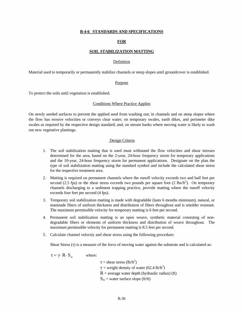
B.36
B-4-6 STANDARDS AND SPECIFICATIONS
FOR
SOIL STABILIZATION MATTING
Definition Material used to temporarily or permanently stabilize channels or steep slopes until groundcover is established.
Purpose To protect the soils until vegetation is established.
Conditions Where Practice Applies
On newly seeded surfaces to prevent the applied seed from washing out; in channels and on steep slopes where the flow has erosive velocities or conveys clear water; on temporary swales, earth dikes, and perimeter dike swales as required by the respective design standard; and, on stream banks where moving water is likely to wash out new vegetative plantings.
Design Criteria
1. The soil stabilization matting that is used must withstand the flow velocities and shear stresses determined for the area, based on the 2-year, 24-hour frequency storm for temporary applications and the 10-year, 24-hour frequency storm for permanent applications. Designate on the plan the type of soil stabilization matting using the standard symbol and include the calculated shear stress for the respective treatment area.
2. Matting is required on permanent channels where the runoff velocity exceeds two and half feet per second (2.5 fps) or the shear stress exceeds two pounds per square foot (2 lbs/ft2). On temporary channels discharging to a sediment trapping practice, provide matting where the runoff velocity exceeds four feet per second (4 fps).
3. Temporary soil stabilization matting is made with degradable (lasts 6 months minimum), natural, or manmade fibers of uniform thickness and distribution of fibers throughout and is smolder resistant. The maximum permissible velocity for temporary matting is 6 feet per second.
4. Permanent soil stabilization matting is an open weave, synthetic material consisting of non-degradable fibers or elements of uniform thickness and distribution of weave throughout. The maximum permissible velocity for permanent matting is 8.5 feet per second.
5. Calculate channel velocity and shear stress using the following procedure:
Shear Stress (τ) is a measure of the force of moving water against the substrate and is calculated as:
wSRγτ ⋅⋅= where:
τ = shear stress (lb/ft2) γ = weight density of water (62.4 lb/ft3) R = average water depth (hydraulic radius) (ft) Sw = water surface slope (ft/ft)
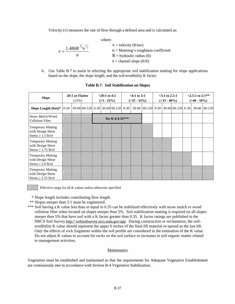
B.37
Velocity (v) measures the rate of flow through a defined area and is calculated as:
ns1.486Rv
21
32
=
where: v = velocity (ft/sec) n = Manning’s roughness coefficient R = hydraulic radius (ft) s = channel slope (ft/ft)
6. Use Table B.7 to assist in selecting the appropriate soil stabilization matting for slope applications
based on the slope, the slope length, and the soil-erodibility K factor.
Table B.7: Soil Stabilization on Slopes
20:1 or Flatter <20:1 to 4:1 <4:1 to 3:1 <3:1 to 2.5:1 <2.5:1 to 2:1** Slope (≤5%) (>5 - 25%) (>25 - 33%) (>33 - 40%) (>40 - 50%)
Slope Length (feet)* 0-30 30-60 60-120 0-30 30-60 60-120 0-30 30-60 60-120 0-30 30-60 60-120 0-30 30-60 60-120
Straw Mulch/Wood Cellulose Fiber for K ≤ 0.35***
Temporary Matting with Design Shear Stress ≥ 1.5 lb/sf
Temporary Matting with Design Shear Stress ≥ 1.75 lb/sf
Temporary Matting with Design Shear Stress ≥ 2.0 lb/sf
Temporary Matting with Design Shear Stress ≥ 2.25 lb/sf
Effective range for all K values unless otherwise specified
* Slope length includes contributing flow length. ** Slopes steeper than 2:1 must be engineered. *** Soil having a K value less than or equal to 0.35 can be stabilized effectively with straw mulch or wood
cellulose fiber when located on slopes steeper than 5%. Soil stabilization matting is required on all slopes steeper than 5% that have soil with a K factor greater than 0.35. K factor ratings are published in the NRCS Soil Survey http:// websoilsurvey.nrcs.usda.gov/app. During construction or reclamation, the soil-erodibility K value should represent the upper 6 inches of the final fill material re-spread as the last lift. Only the effects of rock fragments within the soil profile are considered in the estimation of the K value. Do not adjust K values to account for rocks on the soil surface or increases in soil organic matter related to management activities.
Maintenance
Vegetation must be established and maintained so that the requirements for Adequate Vegetative Establishment are continuously met in accordance with Section B-4 Vegetative Stabilization.

B.38

B.39

B.40
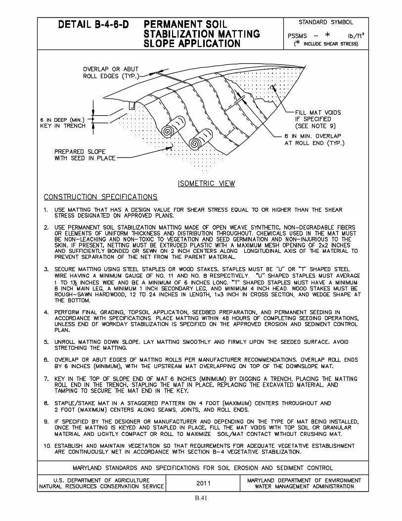
B.41
B.42
B-4-7 STANDARDS AND SPECIFICATIONS
FOR
HEAVY USE AREA PROTECTION
Definition The stabilization of areas frequently and intensively used by surfacing with suitable materials (e.g., mulch and aggregate).
Purpose To provide a stable, non-eroding surface for areas frequently used and to improve the water quality from the runoff of these areas.
Conditions Where Practice Applies This practice applies to intensively used areas (e.g., equipment and material storage, staging areas, heavily used travel lanes).
Criteria
1. A minimum 4-inch base course of crushed stone or other suitable materials including wood chips over nonwoven geotextile should be provided as specified in Section H-1 Materials.
2. Select the stabilizing material based on the intended use, desired maintenance frequency, and runoff control.
3. The transport of sediments, nutrients, oils, chemicals, particulate matter associated with vehicular traffic and equipment, and material storage needs to be considered in the selection of material. Additional control measures may be necessary to control some of these potential pollutants.
4. Surface erosion can be a problem on large heavy use areas. In these situations, measures to reduce the flow length of runoff or erosive velocities need to be considered.
Maintenance
The heavy use areas must be maintained in a condition that minimizes erosion. This may require adding suitable material, as specified on the approved plans, to maintain a clean surface.
B.43
B-4-8 STANDARDS AND SPECIFICATIONS
FOR
STOCKPILE AREA
Definition A mound or pile of soil protected by appropriately designed erosion and sediment control measures.
Purpose To provide a designated location for the temporary storage of soil that controls the potential for erosion, sedimentation, and changes to drainage patterns.
Conditions Where Practice Applies Stockpile areas are utilized when it is necessary to salvage and store soil for later use.
Criteria
1. The stockpile location and all related sediment control practices must be clearly indicated on the erosion and sediment control plan.
2. The footprint of the stockpile must be sized to accommodate the anticipated volume of material and based on a side slope ratio no steeper than 2:1. Benching must be provided in accordance with Section B-3 Land Grading.
3. Runoff from the stockpile area must drain to a suitable sediment control practice.
4. Access the stockpile area from the upgrade side.
5. Clear water runoff into the stockpile area must be minimized by use of a diversion device such as an earth dike, temporary swale or diversion fence. Provisions must be made for discharging concentrated flow in a non-erosive manner.
6. Where runoff concentrates along the toe of the stockpile fill, an appropriate erosion/sediment control practice must be used to intercept the discharge.
7. Stockpiles must be stabilized in accordance with the 3/7 day stabilization requirement as well as Standard B-4-1 Incremental Stabilization and Standard B-4-4 Temporary Stabilization.
8. If the stockpile is located on an impervious surface, a liner should be provided below the stockpile to facilitate cleanup. Stockpiles containing contaminated material must be covered with impermeable sheeting.
Maintenance
The stockpile area must continuously meet the requirements for Adequate Vegetative Establishment in accordance with Section B-4 Vegetative Stabilization. Side slopes must be maintained at no steeper than a 2:1 ratio. The stockpile area must be kept free of erosion. If the vertical height of a stockpile exceeds 20 feet for 2:1 slopes, 30 feet for 3:1 slopes, or 40 feet for 4:1 slopes, benching must be provided in accordance with Section B-3 Land Grading.


SECTION C - WATER CONVEYANCE


C.1
C-1 STANDARDS AND SPECIFICATIONS
FOR
EARTH DIKE
Definition A temporary berm or ridge of soil, compacted, stabilized, and located in such a manner as to direct water to a desired location.
Purpose To direct sediment-laden runoff to a sediment trapping practice or to intercept and divert clear water away from disturbed areas.
Conditions Where Practice Applies Along the limit of disturbance (LOD) or across disturbed areas. Generally, earth dikes remain in place until the disturbed contributory drainage areas are permanently stabilized. Appropriate uses of earth dikes include the following:
1. To divert sediment-laden runoff from a disturbed area to a sediment trapping practice. 2. To segment drainage areas to reduce acreage to sediment control practices. 3. To divert clear water from an undisturbed area to a stabilized outlet at non-erosive velocity.
There are two standard sizes of earth dikes and three types of flow channel stabilization.
Design Criteria
Table C.1: Earth Dike Design Criteria
Dike A Dike B
Drainage Area (See Table C.2) (See Table C.2)
Slope (of dike) (See Table C.2) (See Table C.2)
Dike Height (a) 18 inches 30 inches
Dike Width (b) 24 inches 36 inches
Flow Width (c) 4 feet 6 feet
Flow Depth in Channel (d) 12 inches 24 inches
Side Slopes 2:1 or flatter 2:1 or flatter
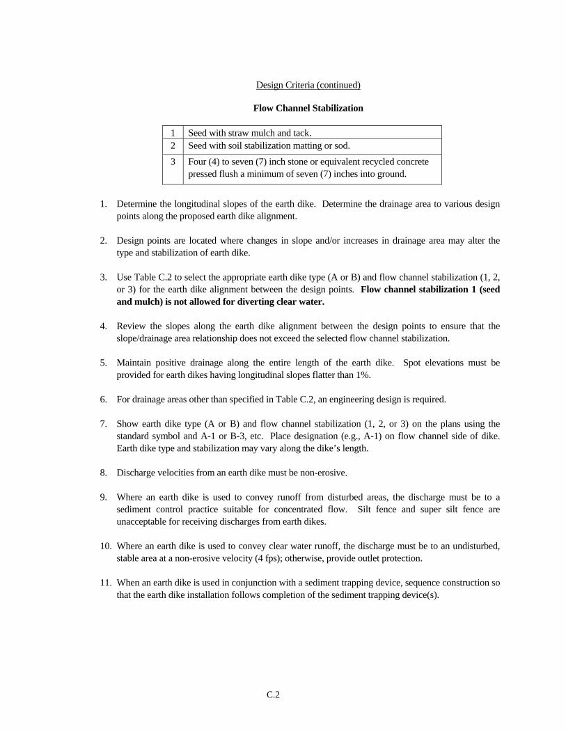
C.2
Design Criteria (continued)
Flow Channel Stabilization
1 Seed with straw mulch and tack. 2 Seed with soil stabilization matting or sod.
3 Four (4) to seven (7) inch stone or equivalent recycled concrete pressed flush a minimum of seven (7) inches into ground.
1. Determine the longitudinal slopes of the earth dike. Determine the drainage area to various design
points along the proposed earth dike alignment. 2. Design points are located where changes in slope and/or increases in drainage area may alter the
type and stabilization of earth dike. 3. Use Table C.2 to select the appropriate earth dike type (A or B) and flow channel stabilization (1, 2,
or 3) for the earth dike alignment between the design points. Flow channel stabilization 1 (seed and mulch) is not allowed for diverting clear water.
4. Review the slopes along the earth dike alignment between the design points to ensure that the
slope/drainage area relationship does not exceed the selected flow channel stabilization. 5. Maintain positive drainage along the entire length of the earth dike. Spot elevations must be
provided for earth dikes having longitudinal slopes flatter than 1%. 6. For drainage areas other than specified in Table C.2, an engineering design is required. 7. Show earth dike type (A or B) and flow channel stabilization (1, 2, or 3) on the plans using the
standard symbol and A-1 or B-3, etc. Place designation (e.g., A-1) on flow channel side of dike. Earth dike type and stabilization may vary along the dike’s length.
8. Discharge velocities from an earth dike must be non-erosive. 9. Where an earth dike is used to convey runoff from disturbed areas, the discharge must be to a
sediment control practice suitable for concentrated flow. Silt fence and super silt fence are unacceptable for receiving discharges from earth dikes.
10. Where an earth dike is used to convey clear water runoff, the discharge must be to an undisturbed,
stable area at a non-erosive velocity (4 fps); otherwise, provide outlet protection.
11. When an earth dike is used in conjunction with a sediment trapping device, sequence construction so that the earth dike installation follows completion of the sediment trapping device(s).
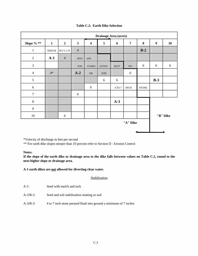
C.3
Table C.2: Earth Dike Selection
Drainage Area (acres)
Slope % ** 1 2 3 4 5 6 7 8 9 10
1 SEED & M U L C H 4 B-2
2 A-1 4 SEED AND
3 SOIL STABILI ZATION MATT ING 6 6 6
4 4* A-2 OR SOD 6
5 6 6 B-3
6 6 4 TO 7 INCH STONE
7 6
8 A-3
9
10 6 "B" Dike
"A" Dike
*Velocity of discharge in feet per second ** For earth dike slopes steeper than 10 percent refer to Section D - Erosion Control Notes: If the slope of the earth dike or drainage area to the dike falls between values on Table C.2, round to the next higher slope or drainage area. A-1 earth dikes are not allowed for diverting clear water.
Stabilization
A-1: Seed with mulch and tack A-2/B-2: Seed and soil stabilization matting or sod A-3/B-3: 4 to 7 inch stone pressed flush into ground a minimum of 7 inches

C.4
Engineering Design Criteria An engineering design may preempt the use of Table C.2. Use the two year frequency storm with NRCS methodologies (i.e., TR-55, TR-20), assuming the worst soil cover conditions to prevail in the contributing drainage area over the life of the earth dike. Use Manning's Equation to determine earth dike flow channel velocities associated with the developed discharges. The Manning's roughness coefficients to be used in the equation are 0.025 for seed and mulch and 0.03 for soil stabilization matting or sod. For 4 to 7 inch stone use 0.045 for flow depths up to 1 foot and 0.038 for flow depths between 1 and 2 feet. The allowable flow channel velocities are < 4 fps for seed and mulch, < 6 fps for stabilization matting or sod, and < 8 fps for 4 to 7 inch stone.
Maintenance The line, grade, and cross section must be maintained. Accumulated sediment and debris must be removed and positive drainage maintained. The earth dike and point of discharge must be kept free of erosion and continuously meet the requirements for Adequate Vegetative Establishment in accordance with Section B-4 Vegetative Stabilization.

C.5
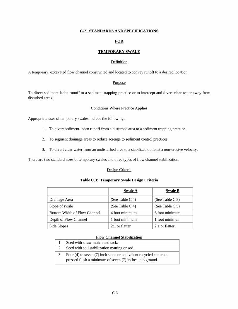
C.6
C-2 STANDARDS AND SPECIFICATIONS
FOR
TEMPORARY SWALE
Definition A temporary, excavated flow channel constructed and located to convey runoff to a desired location.
Purpose To direct sediment-laden runoff to a sediment trapping practice or to intercept and divert clear water away from disturbed areas.
Conditions Where Practice Applies Appropriate uses of temporary swales include the following:
1. To divert sediment-laden runoff from a disturbed area to a sediment trapping practice. 2. To segment drainage areas to reduce acreage to sediment control practices. 3. To divert clear water from an undisturbed area to a stabilized outlet at a non-erosive velocity.
There are two standard sizes of temporary swales and three types of flow channel stabilization.
Design Criteria
Table C.3: Temporary Swale Design Criteria
Swale A Swale B
Drainage Area (See Table C.4) (See Table C.5) Slope of swale (See Table C.4) (See Table C.5) Bottom Width of Flow Channel 4 foot minimum 6 foot minimum Depth of Flow Channel 1 foot minimum 1 foot minimum Side Slopes 2:1 or flatter 2:1 or flatter
Flow Channel Stabilization
1 Seed with straw mulch and tack. 2 Seed with soil stabilization matting or sod.
3
Four (4) to seven (7) inch stone or equivalent recycled concrete pressed flush a minimum of seven (7) inches into ground.
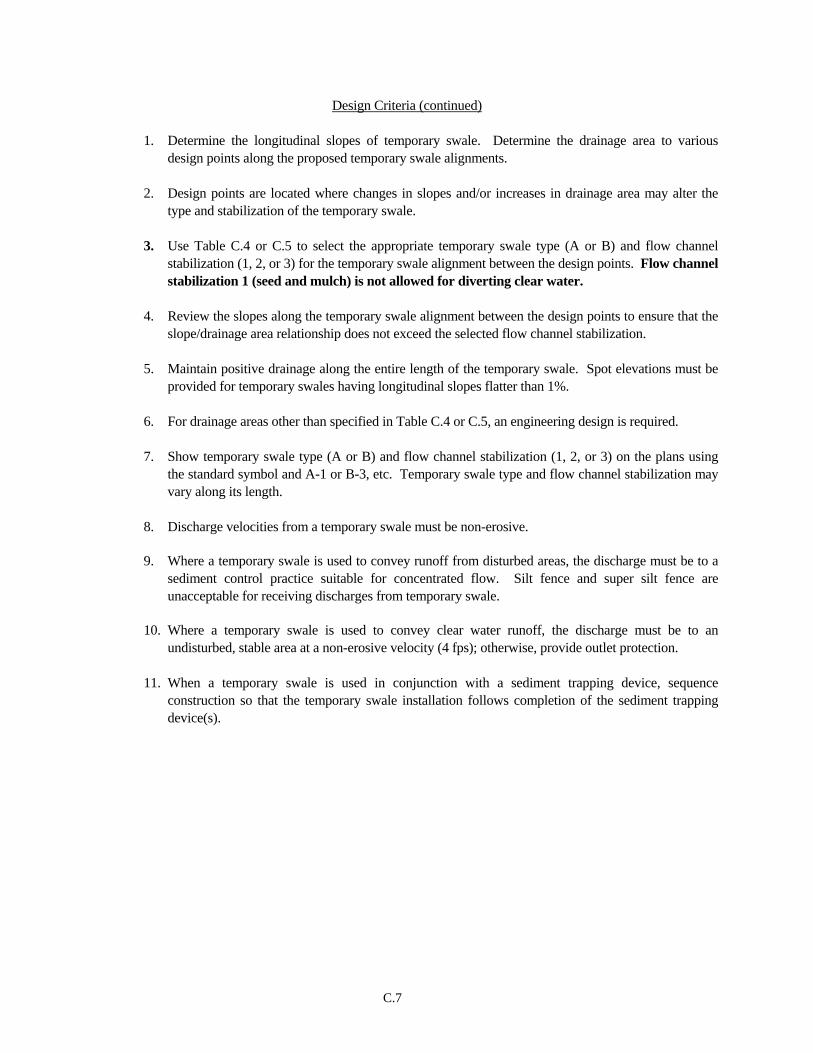
C.7
Design Criteria (continued)
1. Determine the longitudinal slopes of temporary swale. Determine the drainage area to various design points along the proposed temporary swale alignments.
2. Design points are located where changes in slopes and/or increases in drainage area may alter the
type and stabilization of the temporary swale. 3. Use Table C.4 or C.5 to select the appropriate temporary swale type (A or B) and flow channel
stabilization (1, 2, or 3) for the temporary swale alignment between the design points. Flow channel stabilization 1 (seed and mulch) is not allowed for diverting clear water.
4. Review the slopes along the temporary swale alignment between the design points to ensure that the
slope/drainage area relationship does not exceed the selected flow channel stabilization. 5. Maintain positive drainage along the entire length of the temporary swale. Spot elevations must be
provided for temporary swales having longitudinal slopes flatter than 1%. 6. For drainage areas other than specified in Table C.4 or C.5, an engineering design is required. 7. Show temporary swale type (A or B) and flow channel stabilization (1, 2, or 3) on the plans using
the standard symbol and A-1 or B-3, etc. Temporary swale type and flow channel stabilization may vary along its length.
8. Discharge velocities from a temporary swale must be non-erosive. 9. Where a temporary swale is used to convey runoff from disturbed areas, the discharge must be to a
sediment control practice suitable for concentrated flow. Silt fence and super silt fence are unacceptable for receiving discharges from temporary swale.
10. Where a temporary swale is used to convey clear water runoff, the discharge must be to an
undisturbed, stable area at a non-erosive velocity (4 fps); otherwise, provide outlet protection. 11. When a temporary swale is used in conjunction with a sediment trapping device, sequence
construction so that the temporary swale installation follows completion of the sediment trapping device(s).

C.8
Table C.4: Temporary Swale Selection
Swale A: Drainage Area ≤ 5 acres
4 Foot Flat Bottom
Drainage Area (acres) Slope %**
1 2 3 4 5
1 SEED AND
2 MULCH
4 4 4
3 A-1 4 SEED AND
4 SOIL STABILI ZATION MATTING
5 4*
6 A-2
7 6
8 6 A-3
9 4 TO 7 INCH
10 6 STONE
*Velocity of flow in feet/second ** For swale slopes steeper than 10 percent refer to Section D - Erosion Control Notes: If the slope of the swale or drainage area to the swale falls between values on Table C.4, round to the next higher slope or drainage area. A-1 swales are not allowed for diverting clear water.
Stabilization
A-1: Seed with mulch and tack A-2: Seed and soil stabilization matting or sod A-3: 4 to 7 inch stone pressed flush into ground a minimum of 7 inches
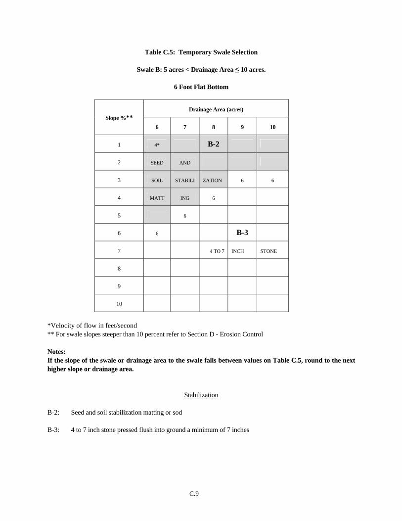
C.9
Table C.5: Temporary Swale Selection
Swale B: 5 acres < Drainage Area ≤ 10 acres.
6 Foot Flat Bottom
Drainage Area (acres) Slope %**
6 7 8 9 10
1 4* B-2
2 SEED AND
3 SOIL STABILI ZATION 6 6
4 MATT ING 6
5 6
6 6 B-3
7 4 TO 7 INCH STONE
8
9
10
*Velocity of flow in feet/second ** For swale slopes steeper than 10 percent refer to Section D - Erosion Control Notes: If the slope of the swale or drainage area to the swale falls between values on Table C.5, round to the next higher slope or drainage area.
Stabilization B-2: Seed and soil stabilization matting or sod B-3: 4 to 7 inch stone pressed flush into ground a minimum of 7 inches

C.10
Engineering Design Criteria
An engineering design may preempt the use of Table C.4 or C.5. Use the 2-year frequency storm with NRCS methodologies (i.e., TR-55, TR-20), assuming the worst soil cover conditions to prevail in the contributing drainage area over the life of the temporary swale. Use the Manning's Equation to determine temporary swale flow channel velocities associated with the developed discharges. The Manning's roughness coefficients to be used in the equation are 0.025 for seed and mulch and 0.03 for soil stabilization matting or sod. For 4 to 7 inch stone use 0.045 for flow depths up to 1 foot and 0.038 for flow depths between 1 and 2 feet. The allowable flow channel velocities are < 4 fps for seed and mulch, < 6 fps for stabilization matting or sod, and < 8 fps for 4 to 7 inch stone. For site conditions exceeding those where Temporary Swale criteria apply, refer to Section H-3 Lined Channel.
Maintenance The line, grade, and cross section must be maintained. Accumulated sediment and debris must be removed and positive drainage maintained. The temporary swale and point of discharge must be kept free of erosion and continuously meet the requirements for Adequate Vegetative Establishment in accordance with Section B-4 Vegetative Stabilization.
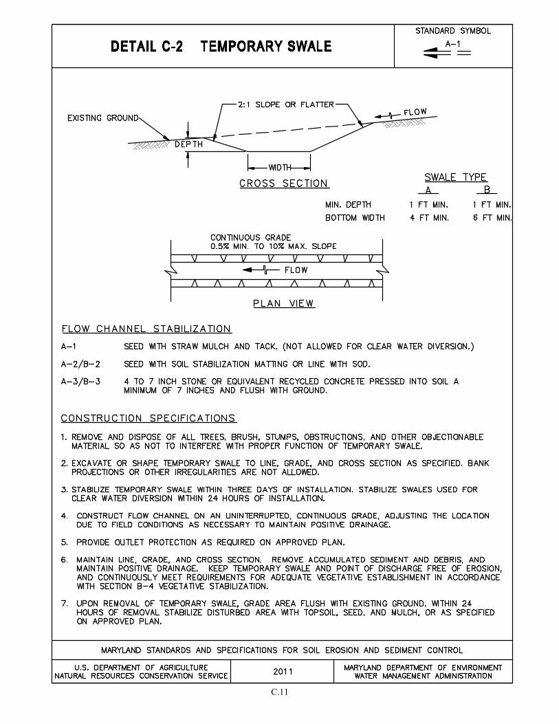
C.11

C.12
C-3 STANDARDS AND SPECIFICATIONS
FOR
PERIMETER DIKE/SWALE
Definition A temporary berm of soil created from excavated material used to form an adjoining channel located along the perimeter of the site or disturbed area.
Purpose To prevent clear water runoff from entering disturbed areas by intercepting and diverting it to a stabilized outlet or to intercept sediment-laden water and divert it to a sediment trapping practice.
Conditions Where Practice Applies Appropriate uses of perimeter dike/swale include the following:
1. To divert sediment-laden runoff from a disturbed area to a sediment trapping practice. 2. To segment drainage areas to reduce acreage to sediment control practices. 3. To divert clear water from an undisturbed area to a stabilized outlet at non-erosive velocity.
There are two types of flow channel stabilization used with perimeter dike/swales.
Design Criteria
PDS Type Drainage Area Stabilization
PDS - 1 1 acre or less Seed and Mulch
PDS - 2 1 to 2 acres Seed and cover with soil stabilization matting or line with sod
Note: PDS -1 is not allowed for clear water diversions.
1. Maximum drainage area for this practice is 2 acres (for drainage areas larger than 2 acres see Detail C-1 Earth Dike or Detail C-2 Temporary Swale).
2. Minimum height from bottom of swale to top of dike; 12 inches evenly divided between dike height
and swale depth. Top width of dike: 1 foot minimum. Bottom width of swale: 1 foot minimum.
3. The slope of the perimeter dike/swale will be dependent upon the topography and must not exceed 10 percent.
4. Determine the longitudinal slopes of perimeter dike/swale. Determine the drainage area to various
design points along the proposed temporary swale alignments.
C.13
5. Design points are located where changes in slopes and/or increases in drainage area may alter the
type and stabilization of the perimeter dike/swale. 6. Use table to select the appropriate perimeter dike/swale type (1 or 2) for the alignment between the
design points. Flow channel stabilization using seed and mulch (PDS-1) is not allowed for diverting clear water.
7. Maintain positive drainage along the entire length of the perimeter dike/swale. Spot elevations must
be provided for perimeter dike/swales having longitudinal slopes flatter than 1%.
8. Show perimeter dike/swale type on the plan using the standard symbol (PDS-1 or PDS-2).
9. Discharge velocities from a perimeter dike/swale must be non-erosive.
10. Where a perimeter dike/swale is used to convey runoff from disturbed areas, the discharge must be to a sediment control practice suitable for concentrated flow. Silt fence and super silt fence are unacceptable for receiving discharges from a perimeter dike/swale.
11. Where a perimeter dike/swale (PDS-2) is used to convey clear water runoff, the discharge must be to
an undisturbed, stable area at a non-erosive velocity (4 fps); otherwise, provide outlet protection. 12. When a perimeter dike/swale is used in conjunction with a sediment trapping device, sequence
construction so that the perimeter dike/swale installation follows completion of the sediment trapping device(s).
Maintenance
The line, grade, and cross section must be maintained. Accumulated sediment and debris must be removed and positive drainage maintained. The perimeter dike/swale and point of discharge must be kept free of erosion and continuously meet the requirements for Adequate Vegetative Establishment in accordance with Section B-4 Vegetative Stabilization.
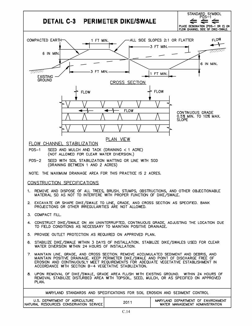
C.14

C.15
C-4 STANDARDS AND SPECIFICATIONS
FOR
TEMPORARY STORM DRAIN DIVERSION
Definition
A temporary swale or pipe that redirects a storm drain system or outfall channel into a sediment trap or basin.
Purpose
To prevent sediment-laden water conveyed by the storm drain system from reaching a watercourse or off-site property.
Conditions Where Practice Applies
Where the discharge of a storm drain system can be effectively conveyed to a sediment trapping device. One of the following practices or procedures must be used to temporarily divert the storm drain system:
1. Construction of a sediment trap or basin below a permanent storm drain outfall: the storm drain system outfalls into a temporary basin or trap constructed below the permanent outfall channel.
2. In-line diversion of storm drain at an inlet or manhole: this diversion requires installing a pipe stub
in the side of a manhole or inlet and temporarily blocking the permanent outfall pipe from that structure. A temporary swale or pipe may be used to convey storm flow from the stub to a sediment trap or basin. Size the diversion swale or pipe based on the storm drain system design criteria (i.e., 10 year storm). This method may be used just above a permanent outfall or prior to connecting into an existing storm drain system.
3. Delay completion of the permanent storm drain outfall and temporarily divert storm flow into a
sediment basin or trap: an earth dike, swale, or designed diversion can be used, depending on the drainage area, to direct flow into a sediment basin or trap.
4. Installation of a stormwater management basin early in the construction sequence: install temporary
measures to allow use as a sediment basin. Because these structures are designed to receive storm drain outfalls, diversion should not be necessary.
Provide the following statement on the plans: Inlet protection is not required and should not be provided if storm drain diversions have been installed and are functioning properly.
C.16
Removal and Restoration
When the areas contributing sediment to the storm drain system have been stabilized, restore the system to its planned use. The following removal and restoration procedure must be included in the sequence of operations for the erosion and sediment control plan:
1. Flush the storm drain system prior to removal or conversion of the trap or basin to remove any accumulated sediment.
2. Establish a permanent stabilized outfall channel as noted on the plan.
3. For sites where an inlet was modified, plug the temporary pipe stub and open the permanent outfall pipe.
4. Restore the area to grades shown on the plan and stabilize with vegetative measures.
Maintenance
Water tight connections must be maintained. Accumulated sediment and debris must be removed. Positive drainage must be maintained.
C.17
C-5 STANDARDS AND SPECIFICATIONS
FOR
TEMPORARY ASPHALT BERM
Definition Temporary, macadam mound used to intercept flow and direct it across pavement.
Purpose To direct sediment-laden runoff to a sediment control practice or to intercept and divert clear water runoff away from disturbed areas.
Conditions Where Practice Applies Across paved areas where other diversion practices are not appropriate. Asphalt berms can also be used to direct runoff into an inlet or in conjunction with inlet protection. The asphalt berm must remain in place until the disturbed contributory drainage areas are stabilized. Appropriate uses of temporary asphalt berms include:
1. To divert sediment-laden runoff from a disturbed area to a sediment control practice.
2. To segment drainage areas.
3. To direct clear water from an undisturbed area at non-erosive rates to a stabilized outlet.
Design Criteria
1. The maximum drainage area to an asphalt berm is 1½ acre.
2. The maximum slope of contributory area is 10 percent.
3. The maximum slope along the berm is 10 percent.
4. Where an asphalt berm is used to convey the runoff diverted from disturbed areas, the discharge must be to a sediment control practice suitable for concentrated flow.
5. When used on an entrance in conjunction with silt fence on pavement, place asphalt berm in a “V” configuration with the apex pointing upgrade.
6. Where an asphalt berm is used to convey clear water runoff, the discharge must be to an undisturbed, stable area at a non-erosive velocity; otherwise, provide outlet protection.
Maintenance
Damaged asphalt must be repaired. Accumulated sediment and debris must be removed and positive drainage maintained.
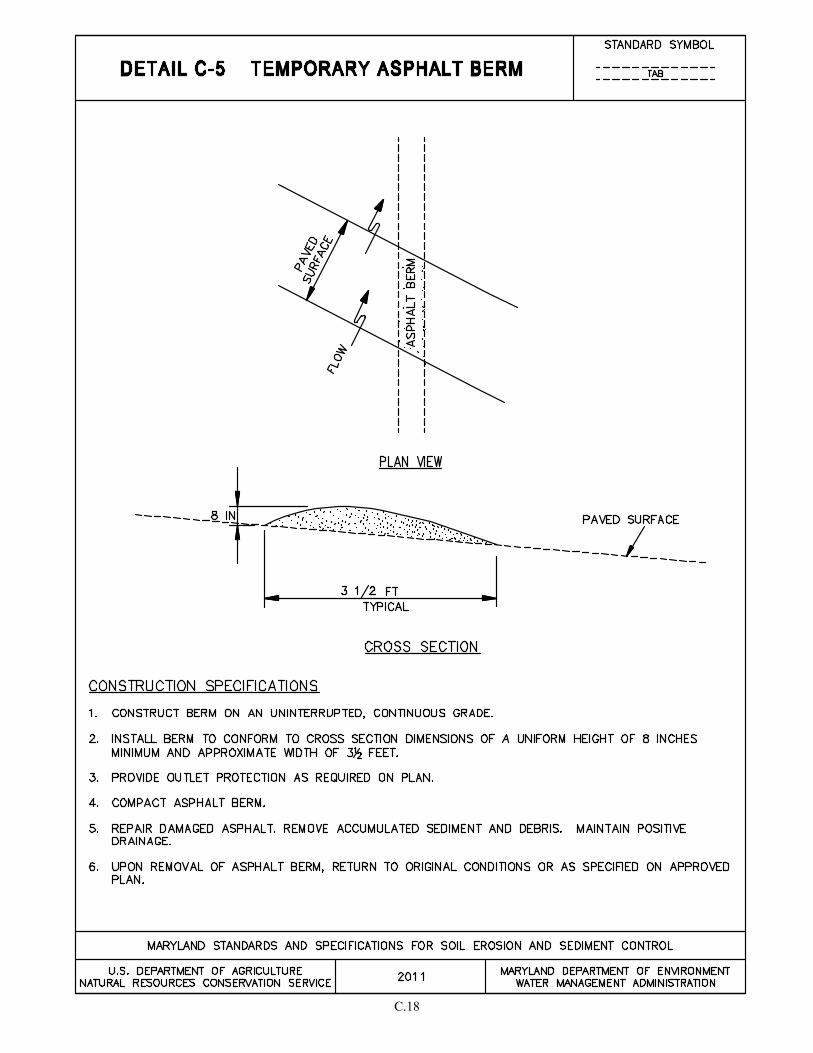
C.18

C.19
C-6 STANDARDS AND SPECIFICATIONS
FOR
CLEAR WATER DIVERSION PIPE
Definition A temporary pipe installed in conjunction with sandbag dikes. Use of flexible pipe is preferred.
Purpose
To convey channel or pipe flow around a work area.
Conditions Where Practice Applies
This practice is used when the proposed work is located in a drainage way.
Design Criteria
Table C.6: Clear Water Diversion Pipe Design Criteria
Maximum Drainage Area (acres)
Pipe Diameter (inches)
0.5 12
1.5 18
2.5 21
3.5 24
5.0 twin 24
1. The height of the sandbag dike must be a minimum of twice the diameter of the diversion pipe.
2. The diversion pipe must outlet onto a stable area at a non-erosive velocity. Provide outlet
protection, if necessary, in accordance with Section D - Erosion Control.
3. If the drainage area to the pipe diversion exceeds 5 acres, an engineering design must be used and based on the two-year storm event.
Note: A waterway construction permit is required when this practice is used to convey base flow for areas designated as waters of the State.
Maintenance
The point of discharge must be kept free of erosion. Water tight connections and positive drainage must be maintained. Sandbags and impermeable sheeting must be replaced if torn.
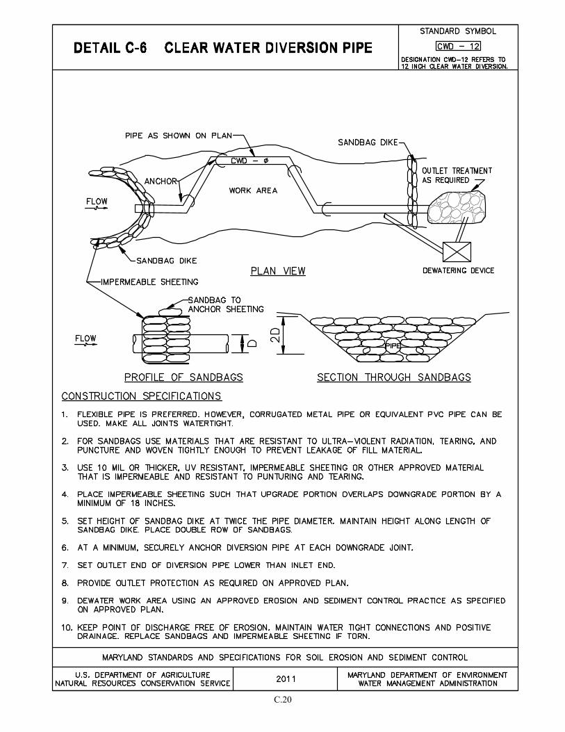
C.20

C.21
C-7 STANDARDS AND SPECIFICATIONS
FOR
TEMPORARY BARRIER DIVERSION
Definition A temporary, structural conveyance consisting of traffic control barriers, sandbags, and a liner.
Purpose To direct clear water channel flow around a work area.
Conditions Where Practice Applies This practice is used when the proposed work is located in a drainage way.
Design Criteria
1. Top elevation of the barrier must be H/2 + 1 foot minimum when the project duration is less than two weeks. Otherwise, use the two-year frequency storm elevation plus 1 foot freeboard. (H is the height of channel bank.) The top elevation must be clearly indicated on the plans.
2. The width of the diversion channel must be at least 45 percent of the channel being diverted.
Note: A waterway construction permit is required when this practice is used in areas designated as waters of the State.
Maintenance
The abutments between concrete barriers must be kept water tight. Sandbags and impermeable sheeting must be replaced if torn.
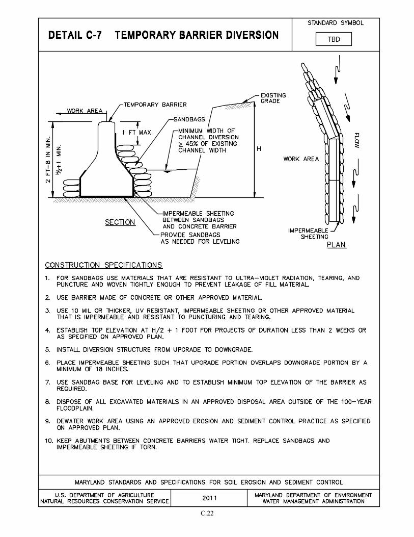
C.22

C.23
C-8 STANDARDS AND SPECIFICATIONS
FOR
MOUNTABLE BERM
Definition
An earth mound covered with geotextile and capped with stone.
Purpose To allow construction vehicles to traverse an earth dike or other sediment control practices.
Conditions Where Practice Applies Interior areas of a site where water conveyance practices need to be crossed by vehicles.
Design Criteria
If a mountable berm is used to cross an earth dike that is conveying clear water, the flow must be piped under the crossing.
Maintenance
The line, grade, and cross section must be maintained. This may require adding stone or making other repairs as conditions demand to maintain the specified dimensions. Accumulated sediment and debris must be removed and positive drainage maintained.
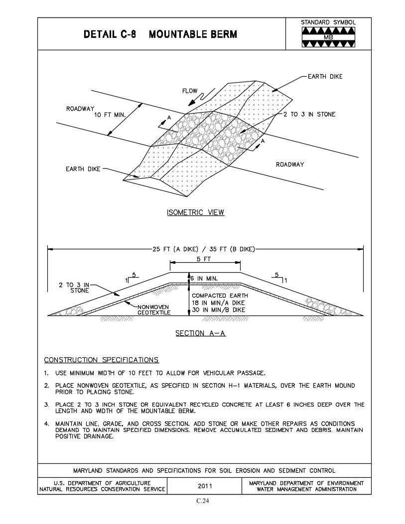
C.24
C.25
C-9 STANDARDS AND SPECIFICATIONS
FOR
DIVERSION FENCE
Definition A temporary barrier of impermeable sheeting over chain link fence located in such a manner as to direct water to a desired location.
Purpose To direct sediment-laden runoff to a sediment trapping practice, or to intercept and divert clear water away from disturbed areas.
Conditions Where Practice Applies
Constructed along the limit of disturbance (LOD) or across disturbed areas, a diversion fence is used when there is insufficient space to construct an earth dike, temporary swale, or perimeter dike swale. Appropriate uses of diversion fences include the following:
1. To divert sediment-laden runoff from a disturbed area to a sediment trapping practice.
2. To segment drainage areas for reducing acreage to sediment control practices.
3. To divert clear water from an undisturbed area to a stable outlet at non-erosive velocities.
Design Criteria
1. The maximum slope along fence is 10 percent.
2. The maximum drainage area is 2 acres.
3. For drainage areas larger than 2 acres, an engineering design may be used based on the 2-year frequency storm with NRCS methodologies (i.e., TR-55, TR-20), assuming the worst soil cover conditions to prevail in the contributing drainage area over the life of the diversion fence.
4. Maintain positive drainage along the entire length of the diversion fence. Spot elevations must be provided for diversion fence having longitudinal slopes flatter than 1%.
5. Discharge velocities from diversion fence must be non-erosive.
6. Where diversion fence is used to convey runoff from disturbed areas, the discharge must be to a sediment control practice suitable for concentrated flow. Silt fence and super silt fence are unacceptable for receiving discharges from diversion fence.
7. Where diversion fence is used to convey clear water runoff, the discharge must be to an undisturbed, stable area at a non-erosive velocity (4 fps); otherwise, provide outlet protection.
8. When diversion fence is used in conjunction with a sediment trapping device, sequence construction

C.26
so that the diversion fence installation follows completion of the sediment trapping device(s).
Maintenance The flow surface along the diversion fence and at the point of discharge must be kept free of erosion. Accumulated sediment and debris must be removed and positive drainage maintained. Impermeable sheeting must be replaced if torn. If undermining occurs, reinstall fence.
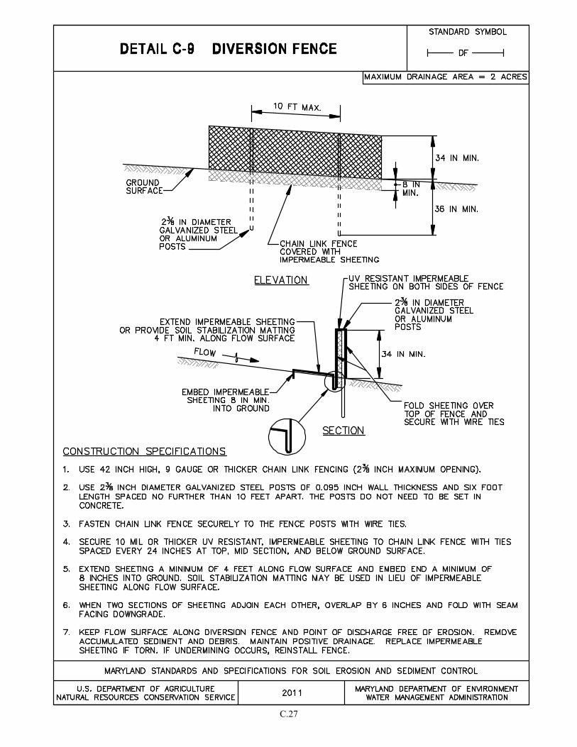
C.27


SECTION D – EROSION CONTROL


D.1
D-1 STANDARDS AND SPECIFICATIONS
FOR
PIPE SLOPE DRAIN
Definition
A temporary conduit placed along a slope to convey flow to a desired location. Use of flexible piping is
preferred.
Purpose
To safely convey concentrated flow down the face of a slope.
Conditions Where Practice Applies
On fill slopes in conjunction with earth dikes. The dikes direct surface runoff to the slope drain which conveys
the concentrated flow down the face of the slope.
Design Criteria
1. The maximum drainage area is 7 acres.
2. The pipe slope drain must be at a 3 percent grade or steeper.
3. The location and discharge velocity determine the type of protection required (e.g., erosion
control matting, rock outlet protection, inflow protection). At a minimum the last 4 feet of pipe
must be at a slope flatter than 1%.
4. For flows from a disturbed area, the discharge must be directed to a sediment trapping practice.
5. At the inlet end of the pipe slope drain, the height of the earth dike must be 2 times the pipe
diameter measured from the invert of the pipe. Extend the top elevation of the dike at zero
percent grade until it intercepts the top of the adjoining perimeter dike(s).
Maintenance
The points of inflow and outflow must be kept free of erosion. Water tight connections and positive drainage
must be maintained. Accumulated sediments and debris must be removed.
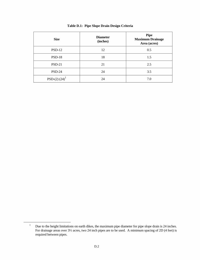
D.2
Table D.1: Pipe Slope Drain Design Criteria
Size Diameter
(inches)
Pipe
Maximum Drainage
Area (acres)
PSD-12 12 0.5
PSD-18 18 1.5
PSD-21 21 2.5
PSD-24 24 3.5
PSD-(2) (24)1 24 7.0
1 Due to the height limitations on earth dikes, the maximum pipe diameter for pipe slope drain is 24 inches.
For drainage areas over 3½ acres, two 24 inch pipes are to be used. A minimum spacing of 2D (4 feet) is
required between pipes.
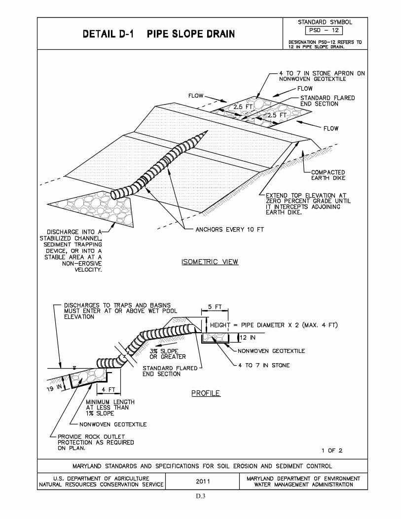
D.3
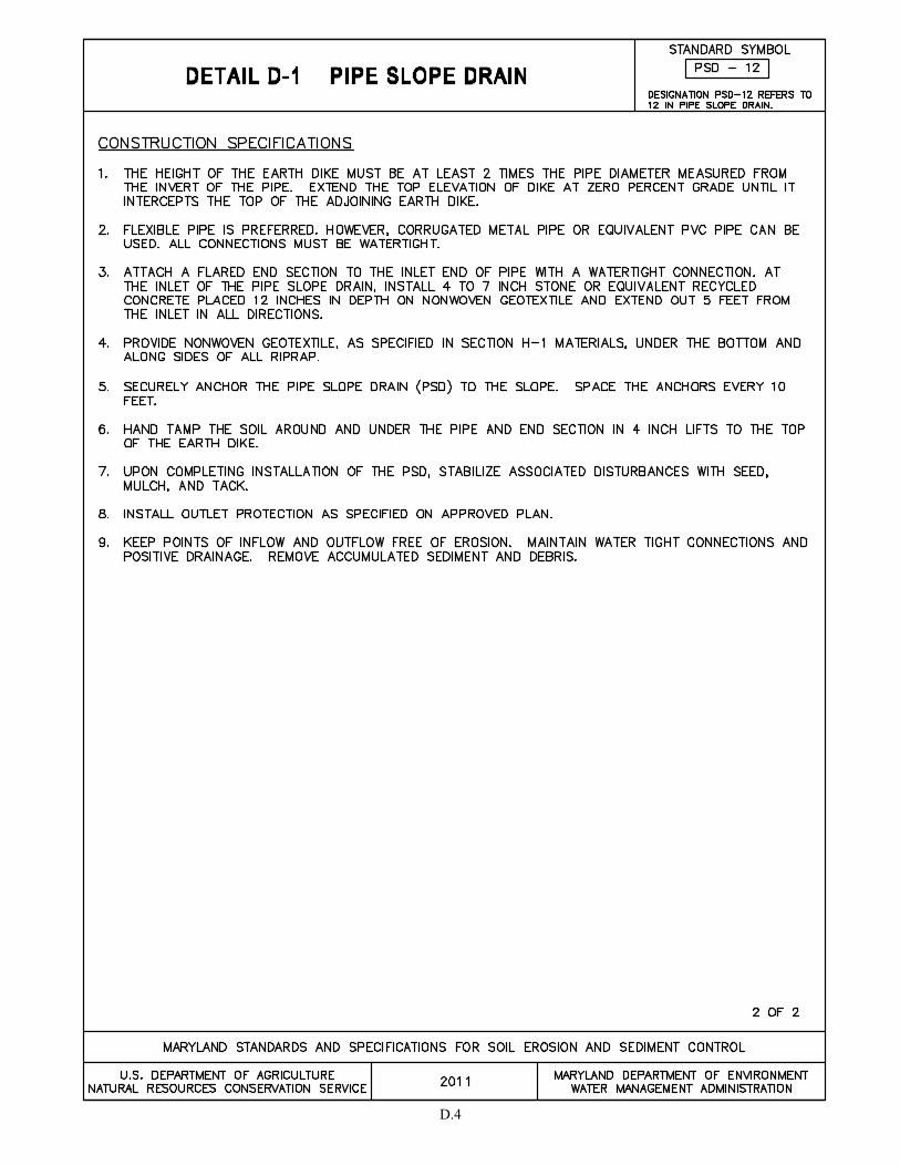
D.4
D.5
D-2 STANDARDS AND SPECIFICATIONS
FOR
STONE CHECK DAM
Definition
A stone weir placed in a swale.
Purpose
To reduce runoff velocities and prevent channel erosion in drainage courses.
Conditions Where Practice Applies
Stone check dams are used in swales where channel velocity exceeds 4 feet per second and channel protection
(e.g., matting or rip-rap) is not provided.
Design Criteria
1. This practice is not to be used as a sediment trapping device. Sediment-laden runoff must pass
through a sediment trapping practice prior to being discharged from the site.
2. Velocity calculations are to be based on the 2-year, 24-hour frequency storm event.
3. Locate stone check dam(s) to provide maximum velocity reduction. This may be achieved by
considering the volume of runoff, the drainage area, and the slope. Place stone check dams in
reasonably straight sections of the flow channel to minimize the potential for erosion in the
channel bend.
4. The height of the stone outlet weir crest must not exceed one-half the depth of the swale.
Additionally, the maximum height to the weir crest must not exceed 2 feet to prevent scour at
the toe of the dam. The stone check dam must extend from bank to bank of the swale with the
weir section length in the center of the dam. If these provisions cannot be met, an engineering
analysis must be conducted.
5. The number of check dams will depend on the length and slope of the swale. The distance
between the stone check dams will vary with the longitudinal slope.
6. The required spacing is determined by the following formula or Figure D.1:
X = Y
S
where:
X = check dam spacing (ft)
Y = check dam height (ft)
S = natural channel slope (ft/ft)
The spacing requirements do not change significantly with varying channel cross sections but
are more sensitive to the channel slope and height of the check dam.

D.6
Maintenance
The stone check dam is not a sediment trapping practice; however, some sediment may accumulate behind the
check dam. Accumulated sediment must be removed when it reaches one-half of the height of the weir crest.
Line, grade, and cross section must be maintained.
Check Dam Removal
In temporary swales and channels, remove check dam(s) when no longer needed. In permanent channels, check
dams may be removed when permanent lining is installed. In the case of grass-lined channels, check dam may be
removed when the grass has matured sufficiently to protect the swale or channel. Seed and install soil
stabilization matting or sod in the areas disturbed by the removal of the check dam.

D.7
Figure D.1: Check Dam Spacing and Height
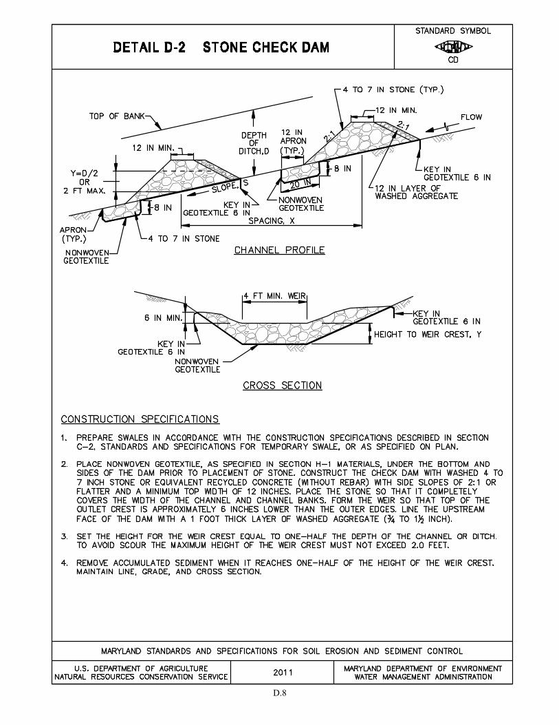
D.8

D.9
D-3 STANDARDS AND SPECIFICATIONS
FOR
INFLOW PROTECTION
D-3-1 RIPRAP INFLOW PROTECTION
Definition
A flow channel lined with rock or recycled concrete equivalent.
Purpose
To provide stable conveyance of concentrated runoff into sediment trapping practices or down steep slopes.
Conditions Where Practice Applies
Where the slope of the inflow channel is steeper than 10:1 but flatter than 4:1. Runoff may be directed to the
inflow channel by means of dikes or swales.
Design Criteria
1. Drainage area is limited to 10 acres. For larger drainage areas an engineered design must be provided
based on adequate and non-erosive flow of runoff from the 2-year storm.
2. This practice may be used for permanent riprap inflow protection when design computations are
provided demonstrating adequate and non-erosive conveyance of the 10-year storm. Recycled concrete
equivalent must not be used in permanent applications.
3. Slopes flatter than 10:1 may be stabilized in accordance with temporary swale or earth dike criteria, as
applicable. For slopes steeper than 4:1, use gabion inflow protection.
Maintenance
The line, grade, and cross section must be maintained. Accumulated sediment and debris must be removed. The
points of inflow and outflow must be kept free of erosion.
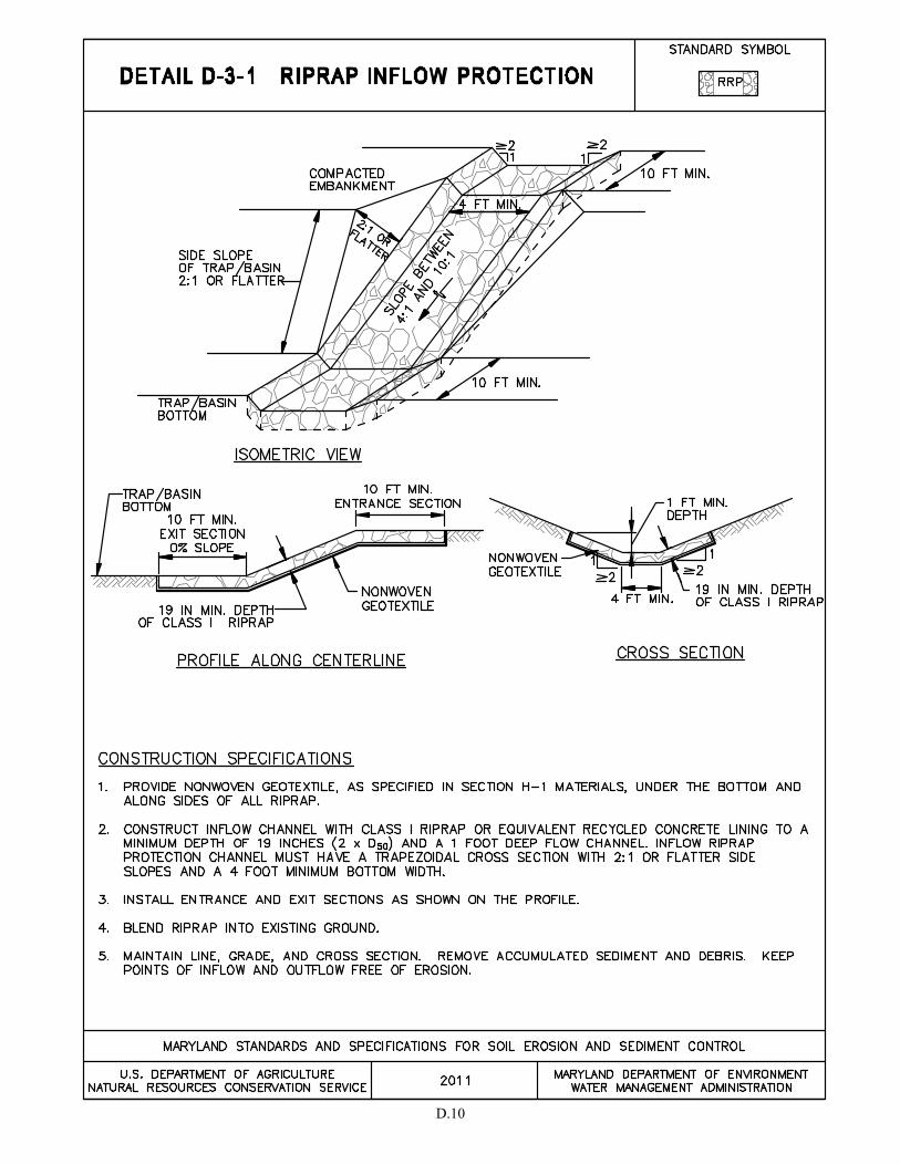
D.10

D.11
D-3-2 STANDARDS AND SPECIFICATIONS
FOR
GABION INFLOW PROTECTION
Definition
A flow channel lined with wire baskets (gabions) filled with rock.
Purpose
To provide stable conveyance of concentrated runoff into sediment trapping practices or down steep slopes.
Conditions Where Practice Applies
Where the slope of the inflow channel is 4:1 or steeper. Runoff may be directed to the inflow channel by means
of dikes or swales.
Design Criteria
1. The drainage area is limited to 10 acres. For larger drainage areas an engineered design must be
provided based on adequate and non-erosive flow of runoff from the 2-year storm.
2. This practice may be used for permanent inflow protection when design computations are provided
demonstrating adequate and non-erosive conveyance of the 10-year storm.
3. For slopes between 4:1 and 10:1, use riprap inflow protection. The maximum allowable inflow channel
slope is 2:1.
Maintenance
The line, grade, and cross section must be maintained. Accumulated sediment and debris must be removed. The
points of inflow and outflow must be kept free of erosion.
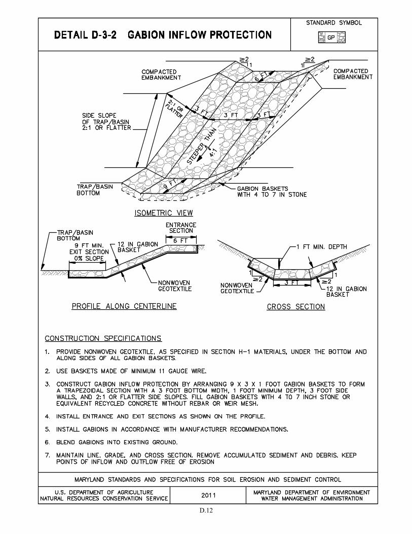
D.12
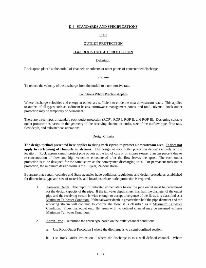
D.13
D-4 STANDARDS AND SPECIFICATIONS
FOR
OUTLET PROTECTION
D-4-1 ROCK OUTLET PROTECTION
Definition
Rock apron placed at the outfall of channels or culverts or other points of concentrated discharge.
Purpose
To reduce the velocity of the discharge from the outfall to a non-erosive rate.
Conditions Where Practice Applies
Where discharge velocities and energy at outlets are sufficient to erode the next downstream reach. This applies
to outlets of all types such as sediment basins, stormwater management ponds, and road culverts. Rock outlet
protection may be temporary or permanent.
There are three types of standard rock outlet protection (ROP): ROP I, ROP II, and ROP III. Designing suitable
outlet protection is based on the geometry of the receiving channel or outlet, size of the outflow pipe, flow rate,
flow depth, and tailwater considerations.
Design Criteria
The design method presented here applies to sizing rock riprap to protect a downstream area. It does not
apply to rock lining of channels or streams. The design of rock outlet protection depends entirely on the
location. Rock aprons cannot protect pipe outlets at the top of cuts or on slopes steeper than ten percent due to
re-concentration of flow and high velocities encountered after the flow leaves the apron. The rock outlet
protection is to be designed for the same storm as the conveyance discharging to it. For permanent rock outlet
protection, the minimum design storm is the 10-year, 24-hour storm.
Be aware that certain counties and State agencies have additional regulations and design procedures established
for dimensions, type and size of materials, and locations where outlet protection is required.
1. Tailwater Depth. The depth of tailwater immediately below the pipe outlet must be determined
for the design capacity of the pipe. If the tailwater depth is less than half the diameter of the outlet
pipe and the receiving stream is wide enough to accept divergence of the flow, it is classified as a
Minimum Tailwater Condition. If the tailwater depth is greater than half the pipe diameter and the
receiving stream will continue to confine the flow, it is classified as a Maximum Tailwater
Condition. Pipes that outlet onto flat areas with no defined channel may be assumed to have
Minimum Tailwater Condition.
2. Apron Type. Determine the apron type based on the outlet channel conditions.
a. Use Rock Outlet Protection I where the discharge is to a semi-confined section.
b. Use Rock Outlet Protection II where the discharge is to a well defined channel. Where
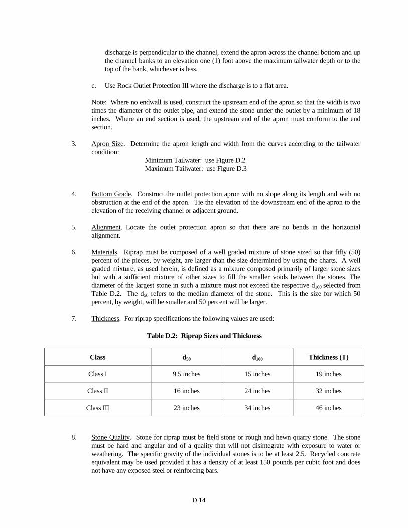
D.14
discharge is perpendicular to the channel, extend the apron across the channel bottom and up
the channel banks to an elevation one (1) foot above the maximum tailwater depth or to the
top of the bank, whichever is less.
c. Use Rock Outlet Protection III where the discharge is to a flat area.
Note: Where no endwall is used, construct the upstream end of the apron so that the width is two
times the diameter of the outlet pipe, and extend the stone under the outlet by a minimum of 18
inches. Where an end section is used, the upstream end of the apron must conform to the end
section.
3. Apron Size. Determine the apron length and width from the curves according to the tailwater
condition:
Minimum Tailwater: use Figure D.2
Maximum Tailwater: use Figure D.3
4. Bottom Grade. Construct the outlet protection apron with no slope along its length and with no
obstruction at the end of the apron. Tie the elevation of the downstream end of the apron to the
elevation of the receiving channel or adjacent ground.
5. Alignment. Locate the outlet protection apron so that there are no bends in the horizontal
alignment.
6. Materials. Riprap must be composed of a well graded mixture of stone sized so that fifty (50)
percent of the pieces, by weight, are larger than the size determined by using the charts. A well
graded mixture, as used herein, is defined as a mixture composed primarily of larger stone sizes
but with a sufficient mixture of other sizes to fill the smaller voids between the stones. The
diameter of the largest stone in such a mixture must not exceed the respective d100 selected from
Table D.2. The d50 refers to the median diameter of the stone. This is the size for which 50
percent, by weight, will be smaller and 50 percent will be larger.
7. Thickness. For riprap specifications the following values are used:
Table D.2: Riprap Sizes and Thickness
Class d50 d100 Thickness (T)
Class I 9.5 inches 15 inches 19 inches
Class II 16 inches 24 inches 32 inches
Class III 23 inches 34 inches 46 inches
8. Stone Quality. Stone for riprap must be field stone or rough and hewn quarry stone. The stone
must be hard and angular and of a quality that will not disintegrate with exposure to water or
weathering. The specific gravity of the individual stones is to be at least 2.5. Recycled concrete
equivalent may be used provided it has a density of at least 150 pounds per cubic foot and does
not have any exposed steel or reinforcing bars.

D.15
9. Filter. A filter is a layer of material placed between the riprap and the underlying soil surface used
to prevent soil movement into and through the riprap, prevent piping, reduce uplift pressure, and
collect water. Riprap must have a filter placed under it in all cases. A filter may be of two general
forms: either a gravel layer or nonwoven geotextile.
10. Plans. The plan must include all the information necessary to properly construct the designed
rock outlet protection. At a minimum the following information must be provided on the plan for
each rock outlet protection:
a. Type (ROP I, II, or III).
b. Riprap size (Class I, II or III).
c. Width, W; length, La; thickness, T.
d. Minimum height of riprap, H.
Design Procedure
1. Investigate the downstream channel to assure that non-erosive velocities can be maintained.
2. Determine the rock outlet protection type (ROP I, II, or III) based on the discharge channel
conditions.
3. Determine the tailwater condition at the outlet to establish which chart to use. (For minimum
tailwater condition use Figure D.2. For maximum tailwater condition use Figure D.3.)
4. Enter the appropriate chart with the pipe diameter (d) and discharge rate (Q) or depth of flow (d)
and discharge velocity (v) to determine the riprap size (d50) and apron length (La) required.
References to pipe diameters in the charts are based on full flow. For other than full pipe flow,
the parameters of depth of flow and velocity must be used. (Refer to the example on Figure D.2
illustrating how to read the chart.) Interpolate between curves for velocities and depth not
shown on chart. Do not extrapolate length of curves.
5. Calculate apron width (W) at the downstream end if a flared section is to be employed.
For minimum tailwater: W ≥ diameter + La
For maximum tailwater: W ≥ diameter + 0.4La
6. Determine the height of riprap. The riprap at the sides of the apron needs to extend up to a
height, H, equal to the maximum depth of flow. For ROP I under maximum tailwater
conditions, the maximum depth of flow is the pipe diameter or the tailwater depth, whichever is
greater. For ROP II under maximum tailwater conditions, the maximum depth of flow equals
the downstream normal depth or the discharge depth, whichever is greater. For minimum
tailwater conditions, H= the discharge depth or d/2, whichever is greater.
Examples
Example 1: Pipe Flow (Full) with Discharge to Unconfined Section:
Q = 280 cfs; diameter = 66 inches; tailwater is 2 feet above pipe invert.
Because the outfall is unconfined, use Rock Outlet Protection III.
Tw < ½ d, therefore minimum tailwater condition controls.

D.16
On Figure D.2 for Q = 280 cfs and d = 66 inches, read d50 = 1.2 feet (14 inches). Then moving
up to the d = 66 curve above, read apron length, La = 38 feet.
Since d50 = 14 inches, use Class II Riprap (d50 = 16 inches).
Apron width, W = diameter + La = 5.5 feet + 38 feet = 43.5 feet.
Include on the plan: ROP III
Class II riprap
La = 38 ft
W = 43.5 ft
T = 32 in
Minimum height of riprap, H = 2.75 ft
Example 2: Pipe Flow (Partial) with Discharge to a Confined Section:
A 48 inch pipe is discharging with a depth of 3 feet; Q = 100 cfs; the discharge velocity = 10 fps
(established from partial flow analysis) to a confined trapezoidal channel with a 2 foot bottom
width, 2:1 side slopes, n = 0.04, and a grade of 0.6 percent; the discharge enters the channel
perpendicularly.
Because the receiving channel is confined, use Rock Outlet Protection II.
Calculations for the downstream channel (using Manning's Equation) indicate a normal depth of
3.1 feet and a normal velocity of 3 fps.
Tw > ½ d, therefore maximum tailwater condition controls.
On Figure D.3, at the intersection of the curves for d = 36 inches and v = 10 fps, read d50 = 0.3
feet. Then moving up to the d = 36 inch curve, read apron length, La = 30 feet.
Since d50 = 3.6 inches, use Class I riprap (d50 = 9.5 inches).
Apron width, W = pipe diameter + 0.4 La = 4 feet + (0.4) (30 feet) = 16 feet. Since the maximum flow depth in this reach is 3.1 feet and the discharge is perpendicular to the
channel, the minimum height of the riprap is 4.1 feet (3.1 ft + 1 ft of freeboard). The apron needs
to be extended across the channel bottom and up the channel banks to 4.1 feet.
Include on the plan: ROP II
Class I riprap
La = 30 ft
W = 16 ft
T = 19 in
Minimum height of riprap, H = 4.1 ft
Example 3: Open Channel Flow with Discharge to Unconfined Section:
A trapezoidal concrete channel 5 feet wide with 2:1 side slopes; flow 2 feet deep; Q = 180 cfs
(velocity = 10 fps); and the tailwater (surface) downstream 0.8 feet.
Because the outlet is unconfined, use Rock Outlet Protection III.
Tw < ½ d channel flow depth, therefore minimum tail water condition controls.
On Figure D.2, at the intersection of the curves for d = 24 inches and v = 10 fps, read d50 = 0.7
feet. Then moving up to the d = 24 inch curve, read apron length, La = 22 feet.
Since d50 = 8.4 inches, use Class I riprap (d50 = 9.5 inches).
Apron width, W = bottom of width of channel + La = 5 feet + 22 feet = 27 feet.
Include on the plan: ROP III
Class I riprap
La = 22 ft
W = 27 ft
T = 19 in
Minimum height of riprap, H = 2 ft
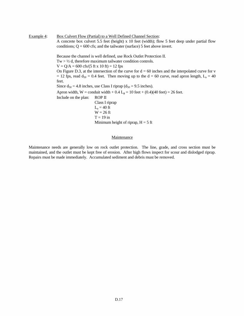
D.17
Example 4: Box Culvert Flow (Partial) to a Well Defined Channel Section:
A concrete box culvert 5.5 feet (height) x 10 feet (width); flow 5 feet deep under partial flow
conditions; Q = 600 cfs; and the tailwater (surface) 5 feet above invert.
Because the channel is well defined, use Rock Outlet Protection II.
Tw > ½ d, therefore maximum tailwater condition controls.
V = Q/A = 600 cfs/(5 ft x 10 ft) = 12 fps
On Figure D.3, at the intersection of the curve for d = 60 inches and the interpolated curve for v
= 12 fps, read d50 = 0.4 feet. Then moving up to the d = 60 curve, read apron length, La = 40
feet.
Since d50 = 4.8 inches, use Class I riprap (d50 = 9.5 inches).
Apron width, W = conduit width + 0.4 La = 10 feet + (0.4)(40 feet) = 26 feet.
Include on the plan: ROP II
Class I riprap
La = 40 ft
W = 26 ft
T = 19 in
Minimum height of riprap, H = 5 ft
Maintenance
Maintenance needs are generally low on rock outlet protection. The line, grade, and cross section must be
maintained, and the outlet must be kept free of erosion. After high flows inspect for scour and dislodged riprap.
Repairs must be made immediately. Accumulated sediment and debris must be removed.
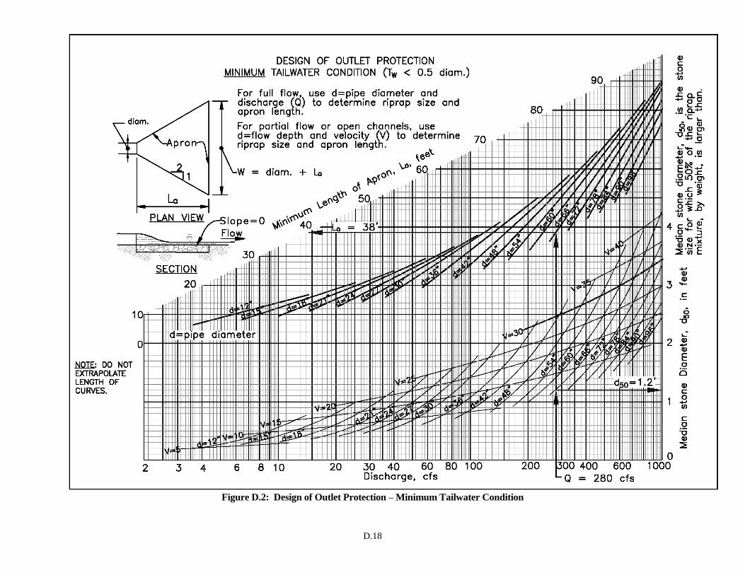
D.18
Figure D.2: Design of Outlet Protection – Minimum Tailwater Condition

D.19
Figure D.3: Design of Outlet Protection – Maximum Tailwater Condition

D.20
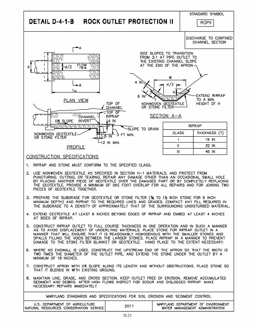
D.21

D.22
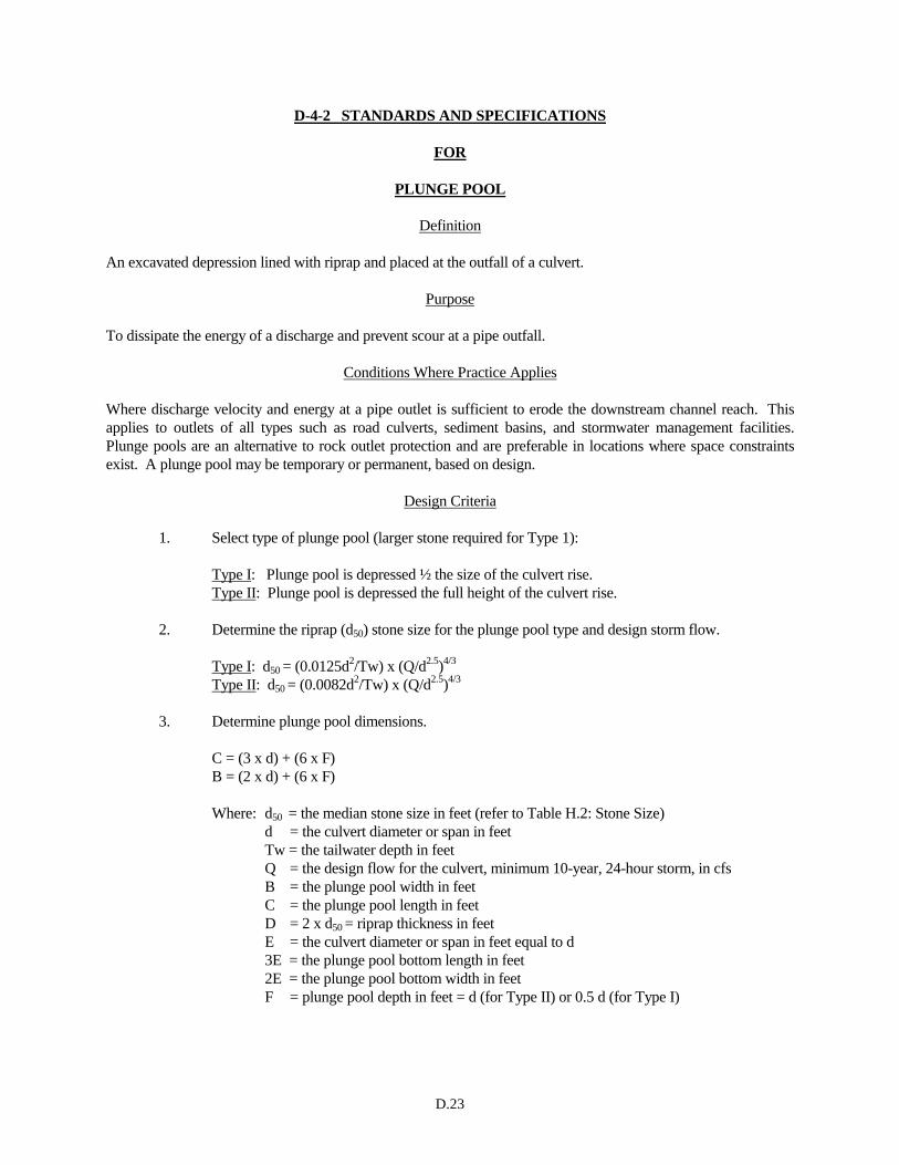
D.23
D-4-2 STANDARDS AND SPECIFICATIONS
FOR
PLUNGE POOL
Definition
An excavated depression lined with riprap and placed at the outfall of a culvert.
Purpose
To dissipate the energy of a discharge and prevent scour at a pipe outfall.
Conditions Where Practice Applies
Where discharge velocity and energy at a pipe outlet is sufficient to erode the downstream channel reach. This
applies to outlets of all types such as road culverts, sediment basins, and stormwater management facilities.
Plunge pools are an alternative to rock outlet protection and are preferable in locations where space constraints
exist. A plunge pool may be temporary or permanent, based on design.
Design Criteria
1. Select type of plunge pool (larger stone required for Type 1):
Type I: Plunge pool is depressed ½ the size of the culvert rise.
Type II: Plunge pool is depressed the full height of the culvert rise.
2. Determine the riprap (d50) stone size for the plunge pool type and design storm flow.
Type I: d50 = (0.0125d2/Tw) x (Q/d
2.5)4/3
Type II: d50 = (0.0082d2/Tw) x (Q/d
2.5)4/3
3. Determine plunge pool dimensions.
C = (3 x d) + (6 x F)
B = (2 x d) + (6 x F)
Where: d50 = the median stone size in feet (refer to Table H.2: Stone Size)
d = the culvert diameter or span in feet
Tw = the tailwater depth in feet
Q = the design flow for the culvert, minimum 10-year, 24-hour storm, in cfs
B = the plunge pool width in feet
C = the plunge pool length in feet
D = 2 x d50 = riprap thickness in feet
E = the culvert diameter or span in feet equal to d
3E = the plunge pool bottom length in feet
2E = the plunge pool bottom width in feet
F = plunge pool depth in feet = d (for Type II) or 0.5 d (for Type I)

D.24
4. For permanent uses, provide a toewall at the downstream end at a depth twice the (D) dimension
and at a width equal to the (D) dimension, on nonwoven geotextile. Extend the rip-rap a
minimum of 18 inches under the outlet pipe if the outlet does not have a footer or headwall.
5. Provide an underdrain to a suitable outfall if standing water in the plunge pool is an issue or as
required by the appropriate approval authority.
6. Provide the design values on the plans for the following dimensions: B, C, D, E, and F.
Maintenance
Maintenance needs are generally low for plunge pools. The line, grade, and cross section must be maintained,
and the outlet must be kept free of erosion. After high flows inspect for scour and dislodged riprap. Repairs must
be made immediately. Accumulated sediment and debris must be removed.
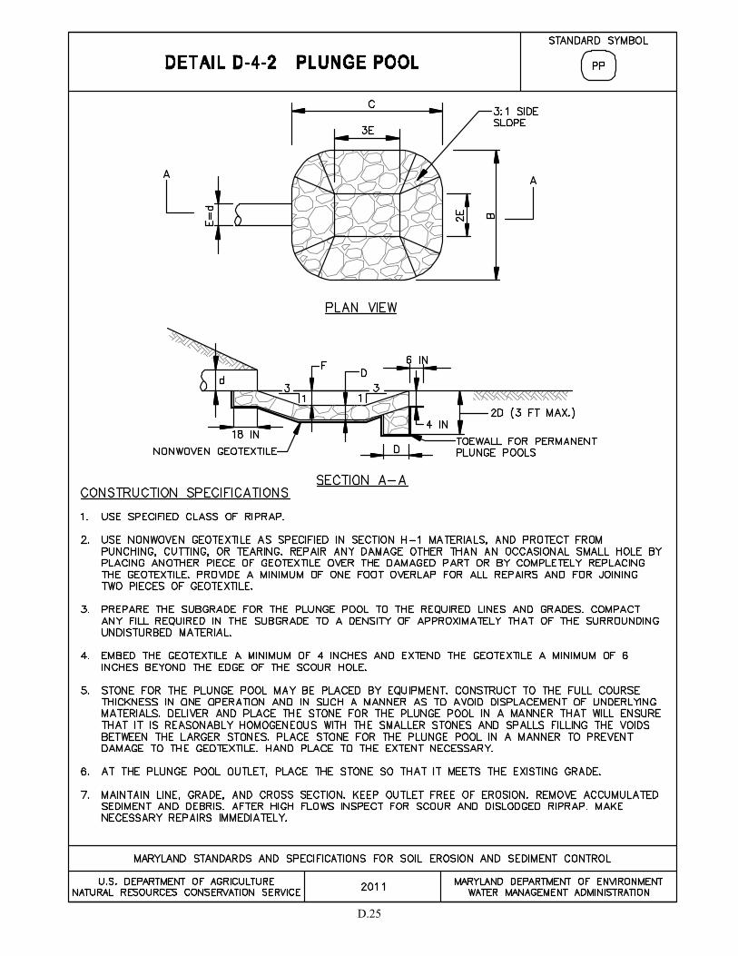
D.25


SECTION E – FILTERING

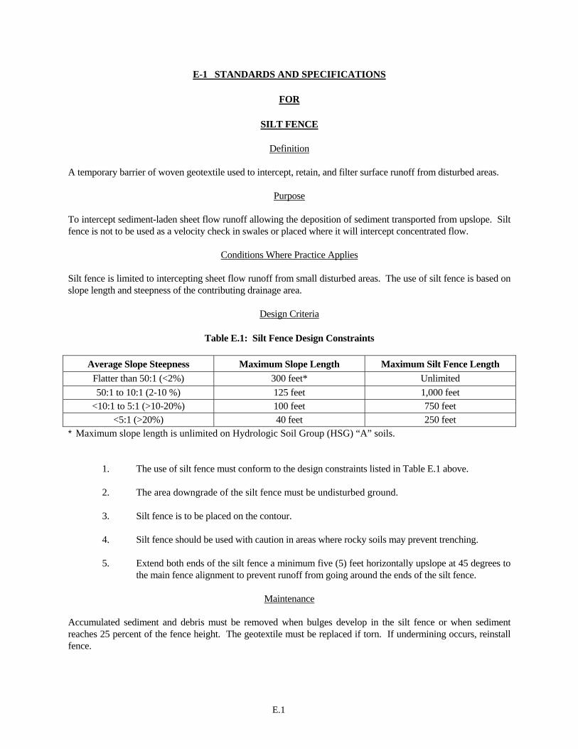
E.1
E-1 STANDARDS AND SPECIFICATIONS
FOR
SILT FENCE
Definition
A temporary barrier of woven geotextile used to intercept, retain, and filter surface runoff from disturbed areas.
Purpose To intercept sediment-laden sheet flow runoff allowing the deposition of sediment transported from upslope. Silt fence is not to be used as a velocity check in swales or placed where it will intercept concentrated flow.
Conditions Where Practice Applies Silt fence is limited to intercepting sheet flow runoff from small disturbed areas. The use of silt fence is based on slope length and steepness of the contributing drainage area.
Design Criteria
Table E.1: Silt Fence Design Constraints
Average Slope Steepness Maximum Slope Length Maximum Silt Fence Length Flatter than 50:1 (<2%) 300 feet* Unlimited 50:1 to 10:1 (2-10 %) 125 feet 1,000 feet
<10:1 to 5:1 (>10-20%) 100 feet 750 feet <5:1 (>20%) 40 feet 250 feet
* Maximum slope length is unlimited on Hydrologic Soil Group (HSG) “A” soils.
1. The use of silt fence must conform to the design constraints listed in Table E.1 above. 2. The area downgrade of the silt fence must be undisturbed ground. 3. Silt fence is to be placed on the contour. 4. Silt fence should be used with caution in areas where rocky soils may prevent trenching. 5. Extend both ends of the silt fence a minimum five (5) feet horizontally upslope at 45 degrees to
the main fence alignment to prevent runoff from going around the ends of the silt fence.
Maintenance Accumulated sediment and debris must be removed when bulges develop in the silt fence or when sediment reaches 25 percent of the fence height. The geotextile must be replaced if torn. If undermining occurs, reinstall fence.
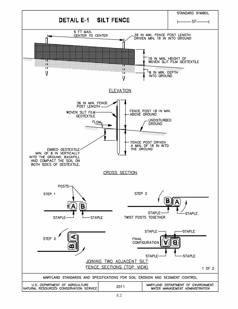
E.2
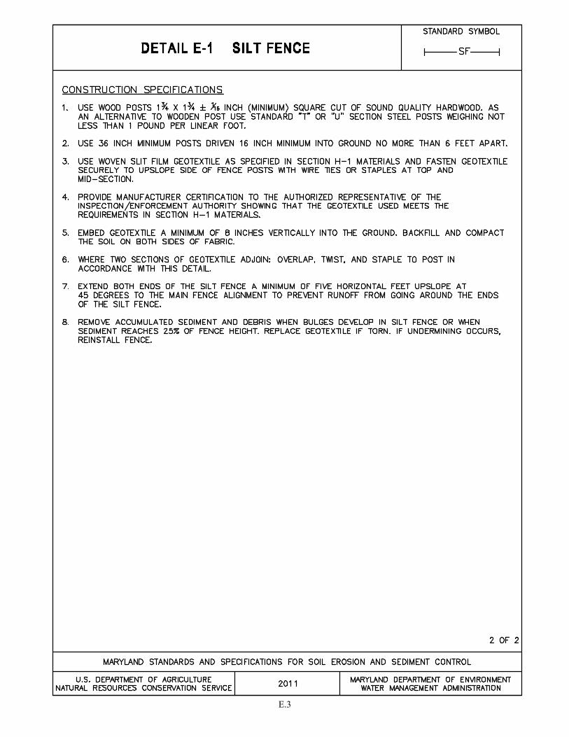
E.3

E.4
E-2 STANDARDS AND SPECIFICATIONS
FOR
SILT FENCE ON PAVEMENT
Definition
A temporary barrier of woven geotextile used to intercept, retain, and filter surface runoff from disturbed areas.
Purpose To intercept sediment-laden sheet flow runoff allowing the deposition of sediment transported from upslope. Silt fence is not to be used where it will intercept concentrated flow.
Conditions Where Practice Applies Silt fence on pavement is limited to intercepting sheet flow runoff from small disturbed areas when standard silt fence cannot be used. The use of silt fence on pavement is based on the slope length and steepness of the contributing drainage area.
Design Criteria
Table E.2: Silt Fence on Pavement Design Constraints
Average Slope Steepness Maximum Slope Length Maximum Silt Fence Length Flatter than 50:1 (<2%) 250 feet 500 feet 50:1 to 10:1 (2-10%) 125 feet 250 feet
<10:1 to 5:1 (>10-20%) 100 feet 200 feet 1. Silt fence on pavement must be placed on the contour. 2. The use of silt fence on pavement must conform to the design constraints listed in Table E.2 above.
Maintenance Accumulated sediment and debris must be removed when bulges develop in the silt fence or when sediment reaches 25 percent of the fence height. The geotextile must be replaced if torn. The water tight seal along the bottom must be maintained and the stone replaced if displaced.
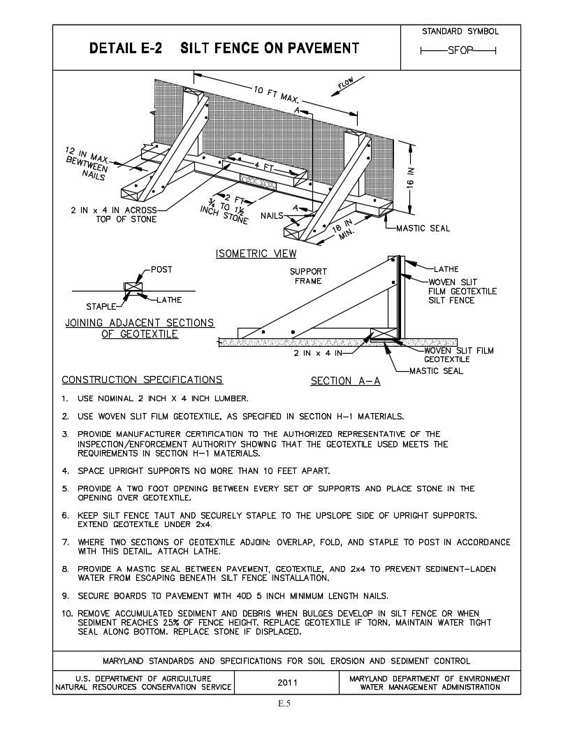
E.5
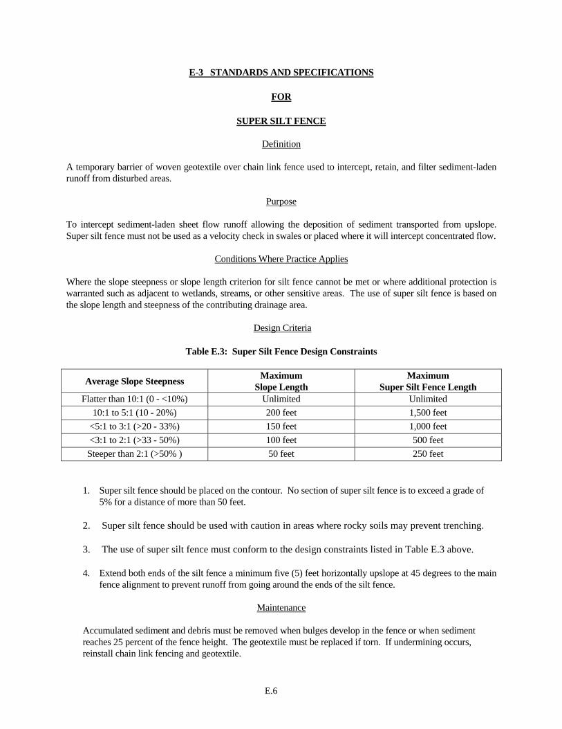
E.6
E-3 STANDARDS AND SPECIFICATIONS
FOR
SUPER SILT FENCE
Definition A temporary barrier of woven geotextile over chain link fence used to intercept, retain, and filter sediment-laden runoff from disturbed areas.
Purpose To intercept sediment-laden sheet flow runoff allowing the deposition of sediment transported from upslope. Super silt fence must not be used as a velocity check in swales or placed where it will intercept concentrated flow.
Conditions Where Practice Applies Where the slope steepness or slope length criterion for silt fence cannot be met or where additional protection is warranted such as adjacent to wetlands, streams, or other sensitive areas. The use of super silt fence is based on the slope length and steepness of the contributing drainage area.
Design Criteria
Table E.3: Super Silt Fence Design Constraints
Average Slope Steepness Maximum Slope Length
Maximum Super Silt Fence Length
Flatter than 10:1 (0 - <10%) Unlimited Unlimited 10:1 to 5:1 (10 - 20%) 200 feet 1,500 feet
<5:1 to 3:1 (>20 - 33%) 150 feet 1,000 feet <3:1 to 2:1 (>33 - 50%) 100 feet 500 feet
Steeper than 2:1 (>50% ) 50 feet 250 feet 1. Super silt fence should be placed on the contour. No section of super silt fence is to exceed a grade of
5% for a distance of more than 50 feet. 2. Super silt fence should be used with caution in areas where rocky soils may prevent trenching. 3. The use of super silt fence must conform to the design constraints listed in Table E.3 above. 4. Extend both ends of the silt fence a minimum five (5) feet horizontally upslope at 45 degrees to the main
fence alignment to prevent runoff from going around the ends of the silt fence.
Maintenance
Accumulated sediment and debris must be removed when bulges develop in the fence or when sediment reaches 25 percent of the fence height. The geotextile must be replaced if torn. If undermining occurs, reinstall chain link fencing and geotextile.
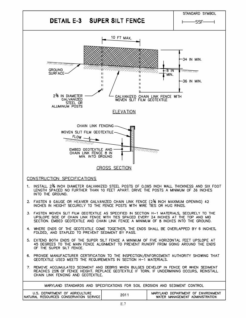
E.7

E.8
E-4 STANDARDS AND SPECIFICATIONS
FOR
CLEAR WATER PIPE THROUGH SILT FENCE OR SUPER SILT FENCE
Definition A pipe extension through silt fence or super silt fence. Use of flexible piping is preferred.
Purpose To provide a mechanism to extend a clear water pipe through silt fence or super silt fence.
Conditions Where Practice Applies
A clear water pipe through silt fence or super silt fence is used when a pipe intersects silt fence or super silt fence.
Design Criteria
1. The pipe and silt fence or super silt fence must conform to the design criteria for the respective practices. The maximum pipe diameter through silt fence is 12 inches and through super silt fence is 24 inches.
2. The plywood baffle is to be placed parallel to the contour. 3. The pipe must outlet onto a stable area at a non-erosive rate.
Maintenance
Accumulated sediment and debris must be removed when sediment reaches 6 inches in height. The geotextile must be replaced if torn. If undermining occurs, reinstall baffle, chain link, and geotextile. The stone must be replaced if displaced. The point of discharge must be kept free of erosion.
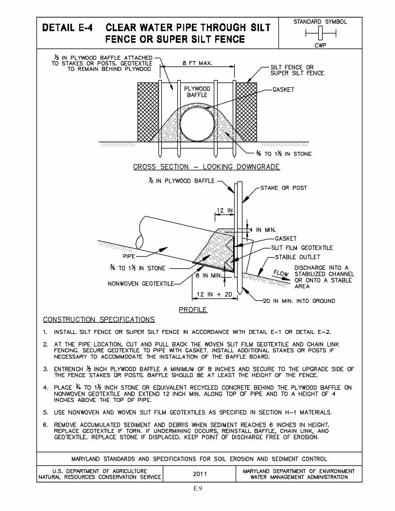
E.9
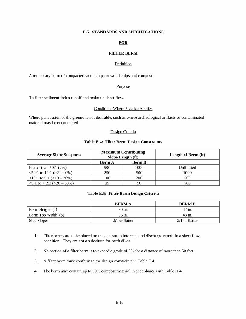
E.10
E-5 STANDARDS AND SPECIFICATIONS
FOR
FILTER BERM
Definition A temporary berm of compacted wood chips or wood chips and compost.
Purpose To filter sediment-laden runoff and maintain sheet flow.
Conditions Where Practice Applies
Where penetration of the ground is not desirable, such as where archeological artifacts or contaminated material may be encountered.
Design Criteria
Table E.4: Filter Berm Design Constraints
Average Slope Steepness Maximum Contributing Slope Length (ft) Length of Berm (ft)
Berm A Berm B Flatter than 50:1 (2%) 500 1000 Unlimited <50:1 to 10:1 (>2 – 10%) 250 500 1000 <10:1 to 5:1 (>10 – 20%) 100 200 500 <5:1 to < 2:1 (>20 – 50%) 25 50 500
Table E.5: Filter Berm Design Criteria
BERM A BERM B
Berm Height (a) 30 in. 42 in. Berm Top Width (b) 36 in. 48 in. Side Slopes 2:1 or flatter 2:1 or flatter
1. Filter berms are to be placed on the contour to intercept and discharge runoff in a sheet flow
condition. They are not a substitute for earth dikes. 2. No section of a filter berm is to exceed a grade of 5% for a distance of more than 50 feet. 3. A filter berm must conform to the design constraints in Table E.4. 4. The berm may contain up to 50% compost material in accordance with Table H.4.

E.11
Maintenance The line, grade, and cross section must be maintained. This may require adding wood chips or making other repairs as conditions demand to maintain the specified dimensions. Accumulated sediment and debris must be removed when they reach 25 percent of the berm height.
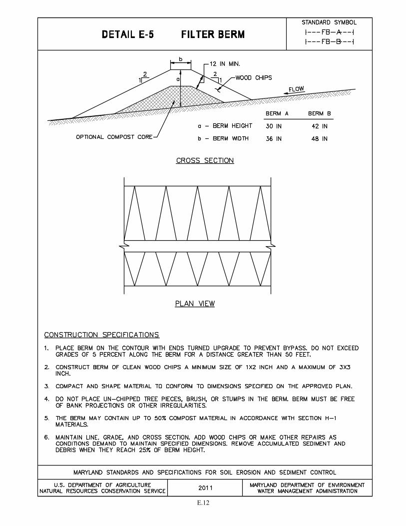
E.12

E.13
E-6 STANDARDS AND SPECIFICATIONS
FOR
FILTER LOG
Definition A temporary, tubular casing filled with compost filter media.
Purpose To intercept sheet flow, retain sediment, and filter runoff through the log media.
Conditions Where Practice Applies
Filter logs are an alternative to silt fence and can be used in hard to reach areas, on frozen ground and pavement, and near tree roots.
Note: fiber rolls are not interchangeable with filter logs. Although similar in appearance, fiber rolls are filled with rice or wheat straw, flax, coconut fiber, or wood excelsior, and are used when stabilizing and revegetating slopes because they slow and spread overland flow, thereby minimizing erosion, rills, and gullies.
Design Criteria
Table E.6: Filter Log Design Constraints
1. Filter logs must be placed on the contour with the ends turned upgrade to prevent bypass. 2. Filter logs can only be used with sheet flow. 3. Filter logs must be used in accordance with the design constraints in Table E.6. 4. The filter media must be compost in accordance with Table H.3 or other approved biodegradable
materials. 5. Filter logs must either be staked every 4 feet maximum, or trenched a minimum of 4 inches into the
ground and staked every 8 feet maximum.
Log Diameter 8 to 15 inches >15 to 24 inches Average Slope Maximum Slope Length (ft)
Flatter than 50:1 (<2%) 125 250 50:1 to 10:1 (2 – 10%) 65 125 <10:1 to 5:1 (>10 – 20%) 50 100 <5:1 to 2:1 (>20 – 50%) N/A 50

E.14
Maintenance
Sediment and debris must be removed and mulch replaced when sediment has accumulated to a depth of one half the exposed height of the log. The filter log must be replaced if clogged or torn. The filter log needs to be reinstalled if undermined or dislodged. For permanent applications, vegetation must be established and maintained so that the requirements for Adequate Vegetative Establishment are met in accordance with Section B-4 Vegetative Stabilization.
E.15
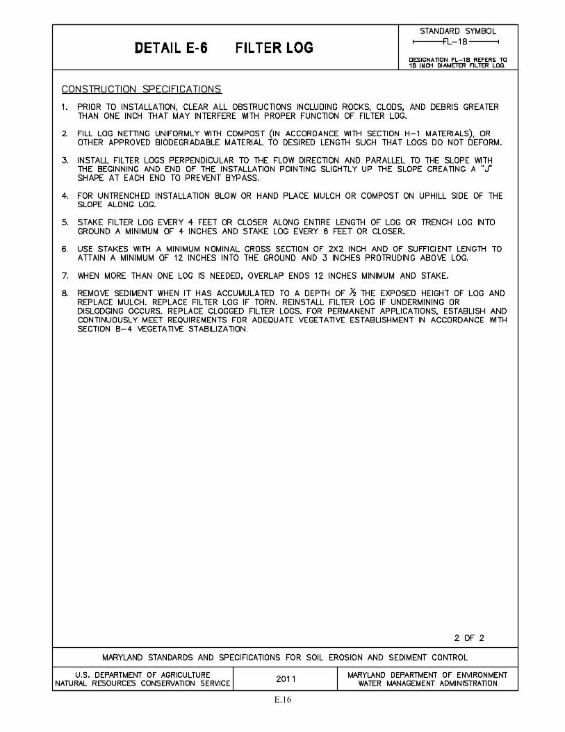
E.16

E.17
E-7 STANDARDS AND SPECIFICATIONS
FOR
TEMPORARY STONE OUTLET STRUCTURE
Definition A stone dam constructed with a weir and faced with geotextile.
Purpose To collect, detain, and filter sediment-laden water as well as provide a protected outlet for small concentrated flows.
Conditions Where Practice Applies Temporary stone outlet structures are installed at points where flow concentrates, typically in combination with earth dikes, and are used where there is a need to discharge runoff through a protected outlet. The drainage area for this practice is limited to ½ acre. For larger drainage areas, temporary gabion structures are used.
Design Criteria
1. The maximum drainage area to this practice is ½ acre. 2. Provide 1800 cubic feet of storage volume per acre of drainage area (900 cu. ft. maximum) behind the
structure. 3. The weir crest must be 6 inches lower than lowest point of connecting dike or other water conveyance
practice. 4. Stone outlet structures should not be used in series.
Maintenance Remove sediment when it has accumulated to within six inches of the weir crest. Replace the geotextile and stone facing when the structure ceases to drain. The line, grade, and cross section must be maintained.

E.18

E.19

E.20
E-8 STANDARDS AND SPECIFICATIONS
FOR
TEMPORARY GABION OUTLET STRUCTURE
Definition A stone dam constructed with a weir and consisting of wire baskets (gabions) filled with rock or recycled concrete equivalent and faced with geotextile and stone.
Purpose
To collect, detain, and filter sediment-laden water as well as provide a protected outlet for concentrated flows.
Conditions Where Practice Applies Temporary gabion outlet structures are installed in ditches, swales, or other points where flow concentrates, typically in combination with earth dikes, and are used where there is a need to discharge runoff through a protected outlet. A temporary gabion outlet structure is used where the drainage area limit for a temporary stone outlet structure is exceeded. The drainage area for this practice is limited to 1½ acres.
Design Criteria
1. The maximum drainage area to this practice is 1½ acres. 2. Provide 1800 cubic feet of storage volume per acre of drainage area (2700 cu. ft. maximum) behind the
structure. 3. Specify the weir crest elevation of the gabion outlet structure on the plan. 4. When a temporary gabion outlet structure is used in conjunction with a standard earth dike, provide a
transition dike on each side of the structure. The height of the transition dike must be at least 4 inches above the top of the gabion basket and must extend at zero percent grade until it intercepts the adjoining earth dike.
Maintenance
Remove sediment when it has accumulated to within twelve inches of the weir crest. Replace the geotextile and stone facing when the structure ceases to function. The line, grade, and cross section must be maintained.
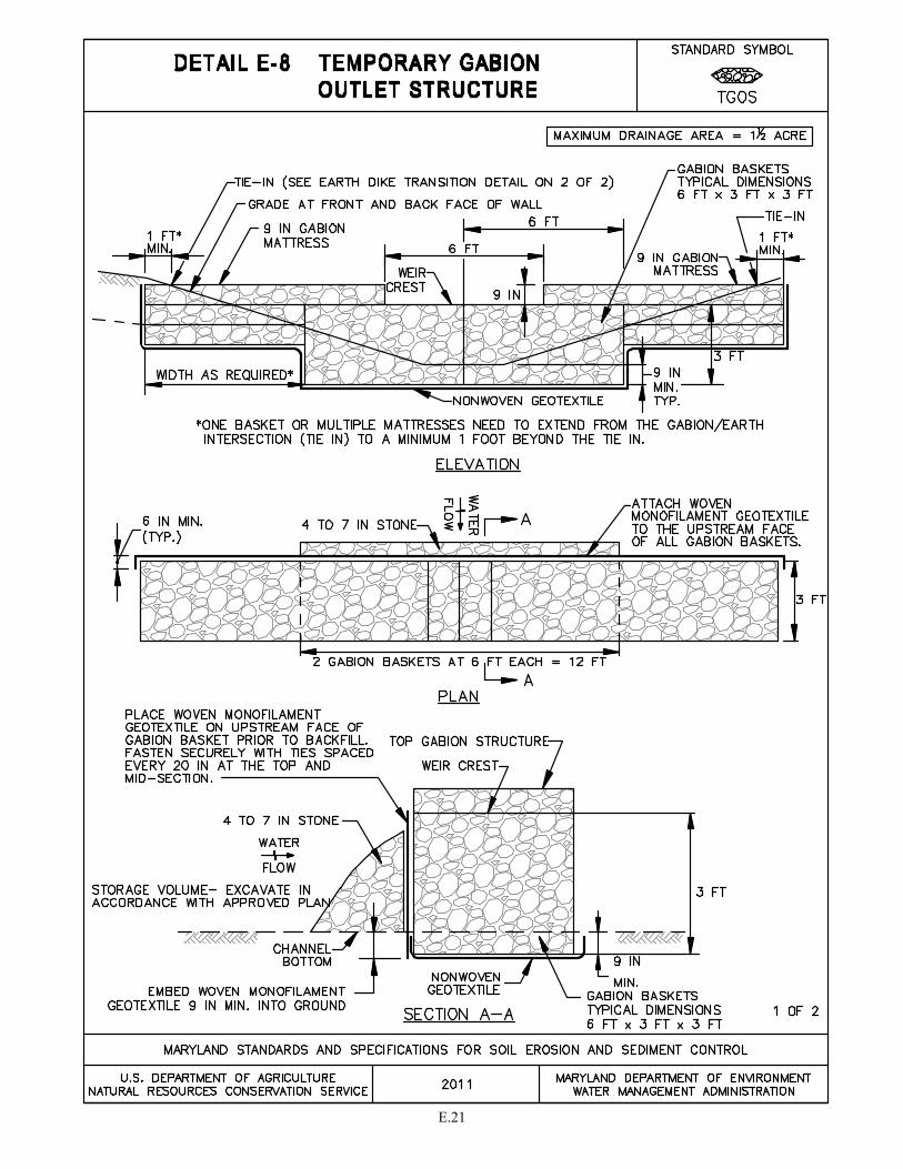
E.21
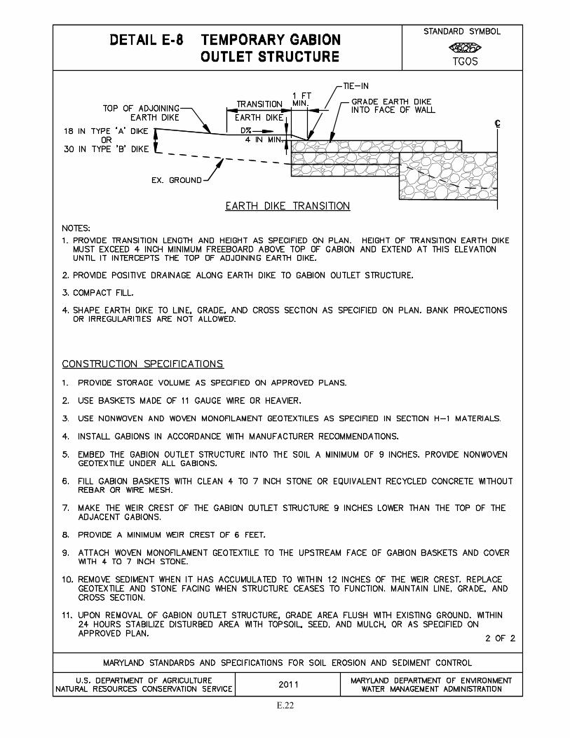
E.22
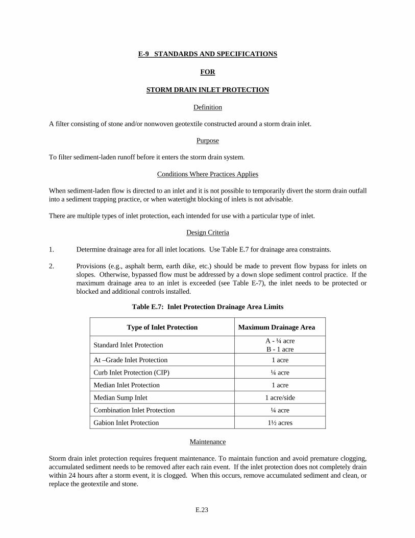
E.23
E-9 STANDARDS AND SPECIFICATIONS
FOR
STORM DRAIN INLET PROTECTION
Definition A filter consisting of stone and/or nonwoven geotextile constructed around a storm drain inlet.
Purpose To filter sediment-laden runoff before it enters the storm drain system.
Conditions Where Practices Applies
When sediment-laden flow is directed to an inlet and it is not possible to temporarily divert the storm drain outfall into a sediment trapping practice, or when watertight blocking of inlets is not advisable. There are multiple types of inlet protection, each intended for use with a particular type of inlet.
Design Criteria
1. Determine drainage area for all inlet locations. Use Table E.7 for drainage area constraints. 2. Provisions (e.g., asphalt berm, earth dike, etc.) should be made to prevent flow bypass for inlets on
slopes. Otherwise, bypassed flow must be addressed by a down slope sediment control practice. If the maximum drainage area to an inlet is exceeded (see Table E-7), the inlet needs to be protected or blocked and additional controls installed.
Table E.7: Inlet Protection Drainage Area Limits
Maintenance
Storm drain inlet protection requires frequent maintenance. To maintain function and avoid premature clogging, accumulated sediment needs to be removed after each rain event. If the inlet protection does not completely drain within 24 hours after a storm event, it is clogged. When this occurs, remove accumulated sediment and clean, or replace the geotextile and stone.
Type of Inlet Protection Maximum Drainage Area
Standard Inlet Protection A - ¼ acre B - 1 acre
At –Grade Inlet Protection 1 acre
Curb Inlet Protection (CIP) ¼ acre
Median Inlet Protection 1 acre
Median Sump Inlet 1 acre/side
Combination Inlet Protection ¼ acre
Gabion Inlet Protection 1½ acres
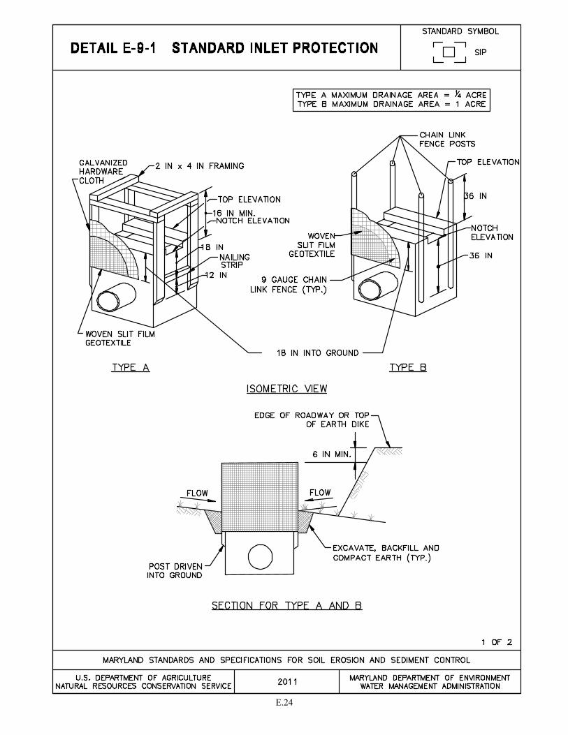
E.24
E.25
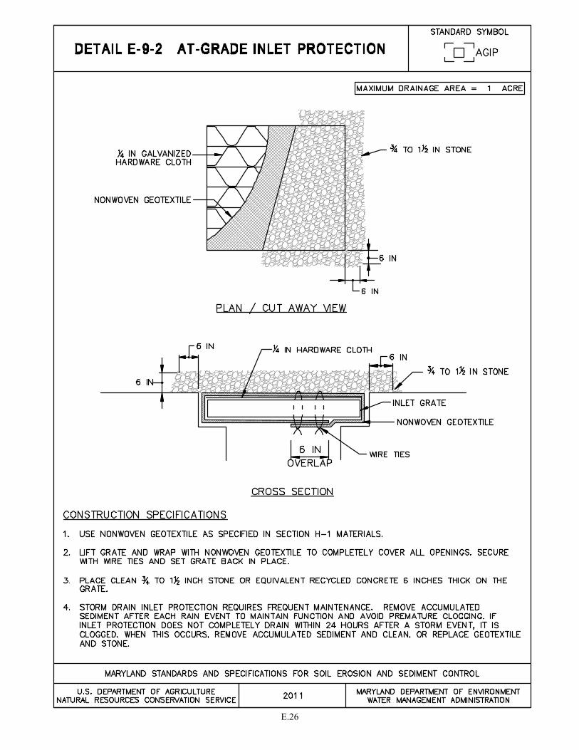
E.26
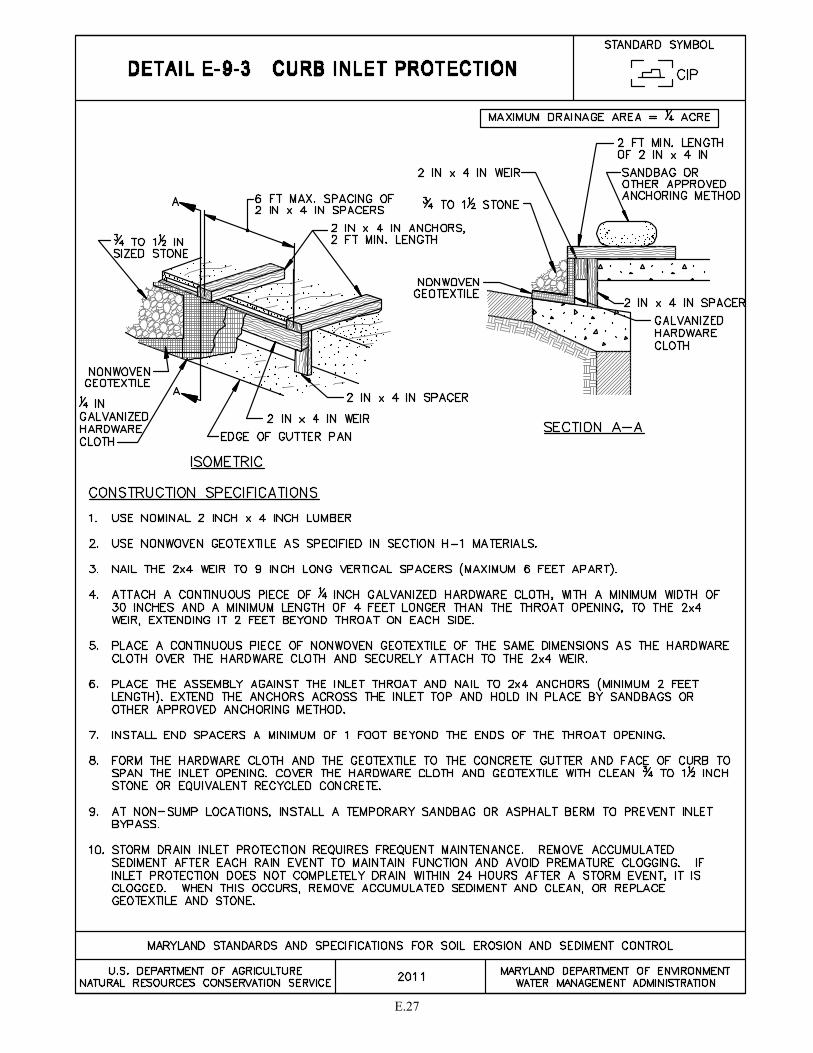
E.27
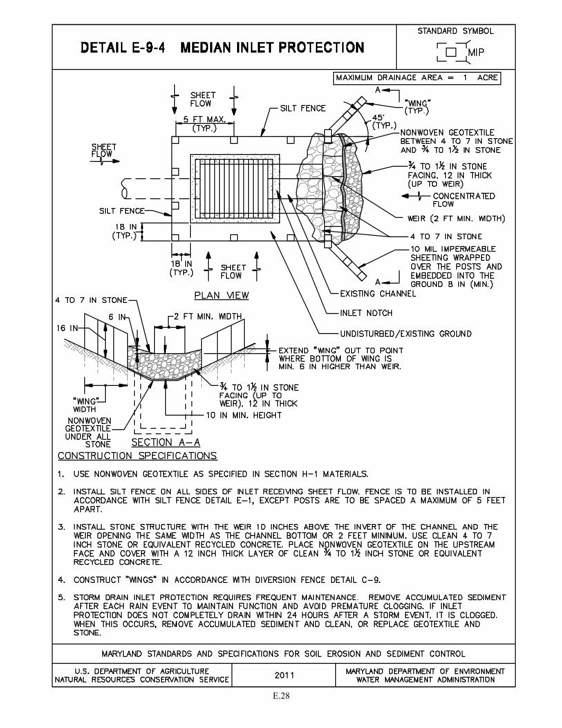
E.28
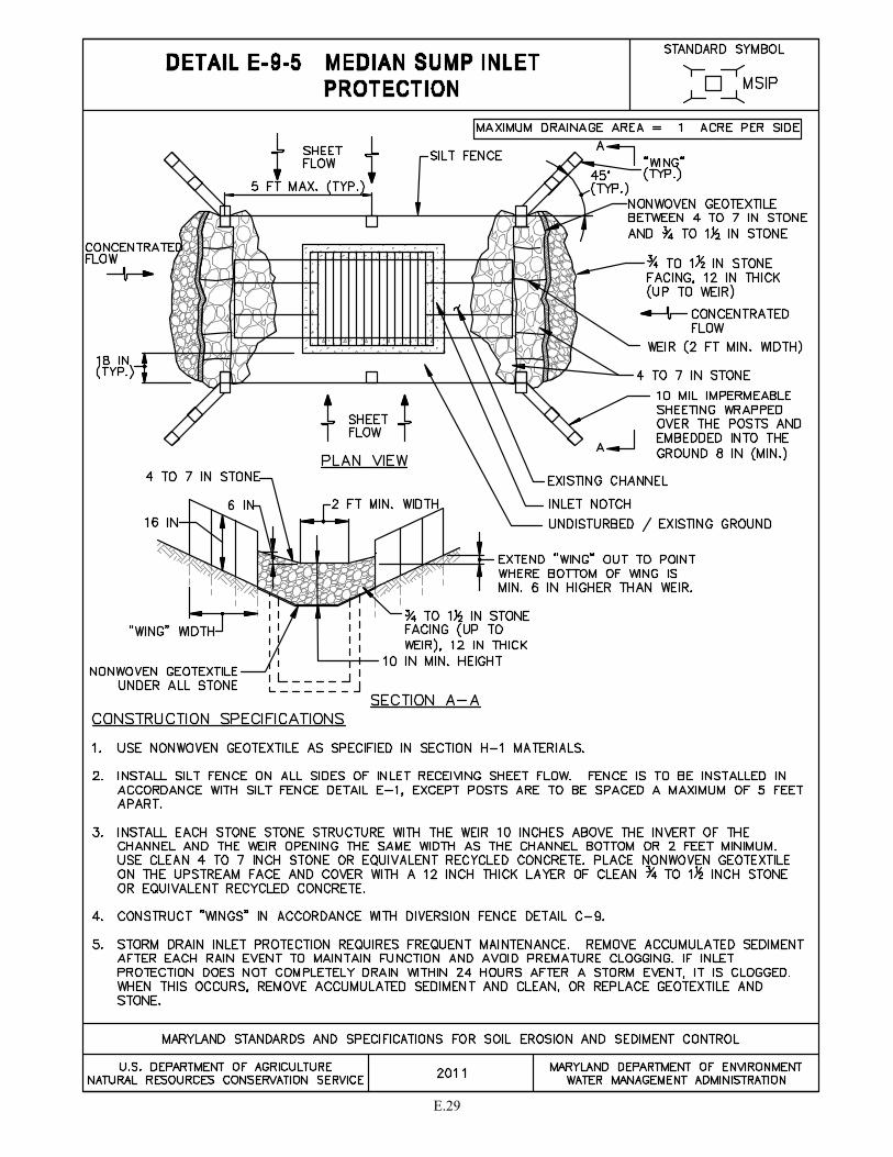
E.29
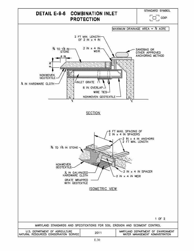
E.30
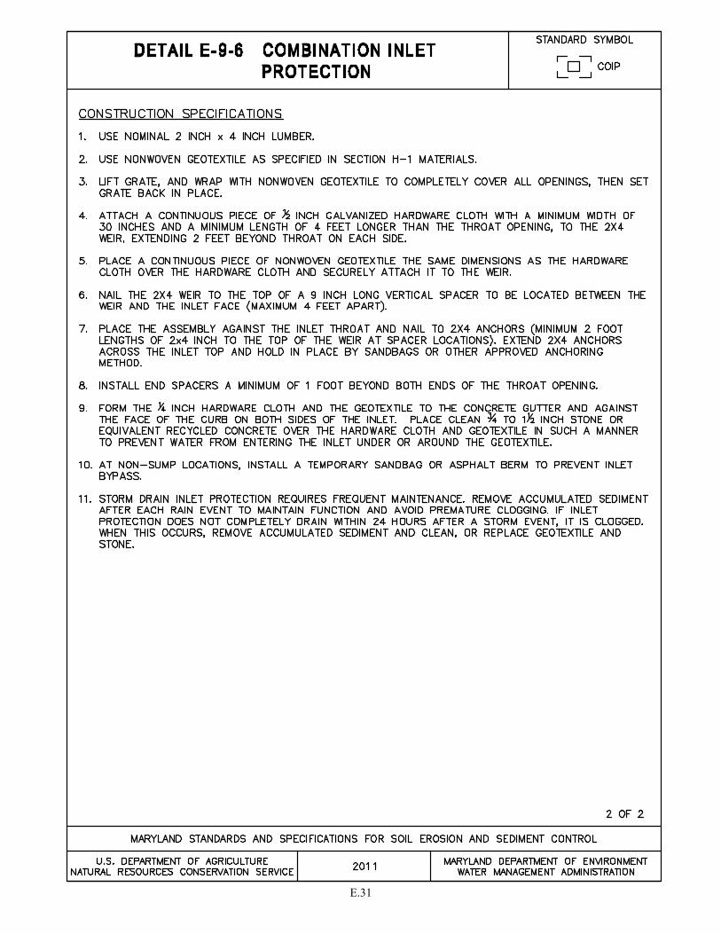
E.31

E.32

SECTION F - DEWATERING


F.1
DEWATERING STRATEGY Dewatering refers to the act of removing water from an excavated area or from a sediment trap/basin on construction sites by retaining the sediment and discharging the clear water. The conditions at a particular construction site may necessitate the use of more than one of these practices, or a combination thereof. Additional treatment beyond an approved dewatering practice may be needed to reduce turbidity in the discharge to receiving waters. Treatments include, but are not limited to: discharging to a vegetative filter; using coagulants to increase settling; or pumping to a sediment trap or basin. The procedures for dewatering must be specified on the plan and included in the sequence of construction. Atypical site conditions may require innovative dewatering designs. Dewatering measures not referenced in this standard may be used with the consent of the approval authority. Pumping sediment-laden water into Waters of the State is strictly prohibited.
APPROVED PRACTICES FOR DEWATERING
1. Detail F-1 Removable Pumping Station.
2. Detail F-2 Sump Pit.
3. Detail F-3 Portable Sediment Tank.
4. Detail F-4 Filter Bag.
5. An approved sediment trap or basin. Pump water to an existing sediment trap or basin where the entire volume can be contained without overflowing to receiving waters or without exceeding the design of the sediment control structure (e.g., do not exceed the dry storage volume or discharge over the weir crest).
F.2
F-1 STANDARDS AND SPECIFICATIONS
FOR
REMOVABLE PUMPING STATION
Definition A perforated, vertical standpipe wrapped with hardware cloth and geotextile and placed inside a larger perforated pipe. The outer pipe is enveloped by hardware cloth and washed stone. Water is pumped from the inner pipe and discharged to a stable area.
Purpose
To remove and filter sediment-laden water from excavations, traps, or basins.
Conditions Where Practice Applies When dewatering is needed in association with excavations, trenches, cofferdams, sediment traps or basins. This practice is preferred over sump pits on projects where a long duration of pumping is expected.
Design Criteria The location of removable pumping stations must be included on the plan. When used in a trap or basin, install pumping station concurrently with the construction of the trap or basin. A removable pumping station may be relocated to optimize its use, but changes to the discharge location must be coordinated with the appropriate enforcement authority.
Maintenance The removable pumping station requires frequent maintenance. If the system clogs, the inner pipe needs to be pulled out and the geotextile replaced. The point of discharge must be kept free of erosion.

F.3
F.4
F-2 STANDARDS AND SPECIFICATIONS
FOR
SUMP PIT
Definition A perforated vertical standpipe wrapped with hardware cloth and geotextile placed in an excavated pit that is backfilled with stone. Water is pumped from the standpipe to a stable discharge area.
Purpose To remove and filter sediment-laden water from excavations.
Conditions Where Practice Applies When dewatering is needed for a short duration (i.e., less than 3 months) in association with excavations, trenches, cofferdams, sediment traps or basins.
Design Criteria The location of sump pits must be included on the plan. A sump pit may be relocated to optimize its use but changes to the discharge location must be coordinated with the appropriate enforcement authority.
Maintenance The sump pit requires frequent maintenance. If the system clogs, the perforated pipe needs to be removed and the geotextile and stone replaced. The point of discharge must be kept free of erosion.

F.5
F.6
F-3 STANDARDS AND SPECIFICATIONS
FOR
PORTABLE SEDIMENT TANK
Definition A compartmented container consisting of a perforated inner pipe lined with hardware cloth and geotextile, placed inside a larger pipe. Water is pumped into the inner pipe and discharged from the outer pipe.
Purpose To settle and filter sediment-laden water prior to discharge.
Conditions Where Practice Applies When dewatering is needed in association with excavations, trenches, cofferdams, sediment traps or basins, especially where excavations are deep or space is limited.
Design Criteria The sediment tank is to be shown on the plan and located for ease of clean-out and disposal of the trapped sediment.
Maintenance The portable sediment tank requires frequent maintenance. Remove accumulated sediment from inner pipe when it reaches two feet in depth. If the system clogs, the inner pipe needs to be pulled out, accumulated sediment removed, and the geotextile replaced. The point of discharge must be kept free of erosion.
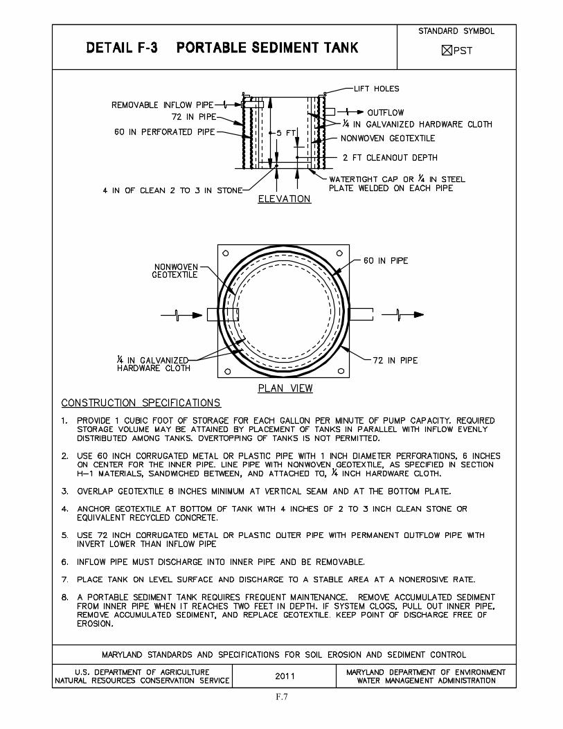
F.7

F.8
F-4 STANDARDS AND SPECIFICATIONS
FOR
FILTER BAG
Definition A geotextile bag through which sediment-laden water is pumped.
Purpose To filter sediment-laden water prior to discharge.
Conditions Where Practice Applies When dewatering is needed in association with excavations, trenches, cofferdams, sediment traps or basins.
Design Criteria The filter bag should be placed in a location that allows for ease of disposal of the trapped sediment and has minimal interference with construction activities and pedestrian traffic.
Maintenance
If the filter bag clogs, it needs to be replaced. Rips, tears, and punctures also necessitate replacement of the filter bag. The connection between the pump hose and the filter bag needs to be kept water tight during operation. If the bedding becomes displaced, it must be replaced.
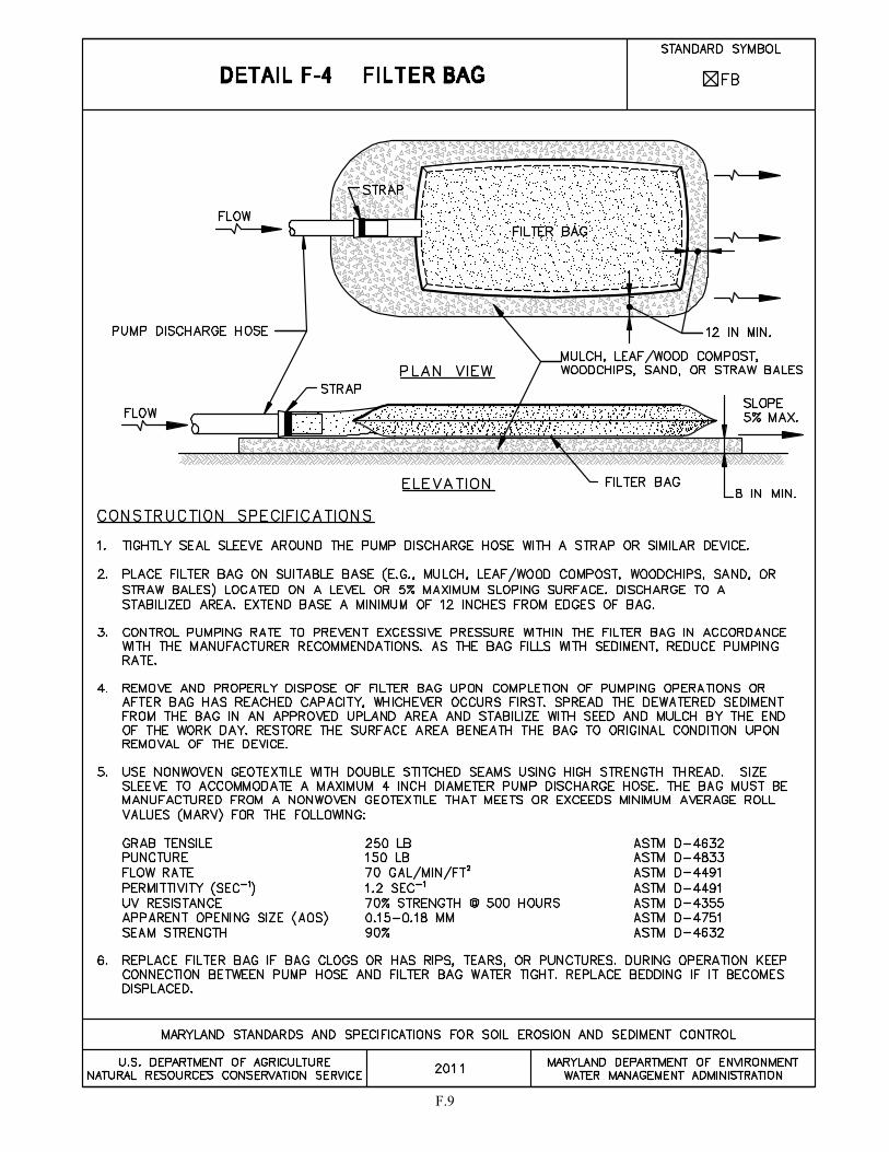
F.9


SECTION G – SEDIMENT TRAPPING

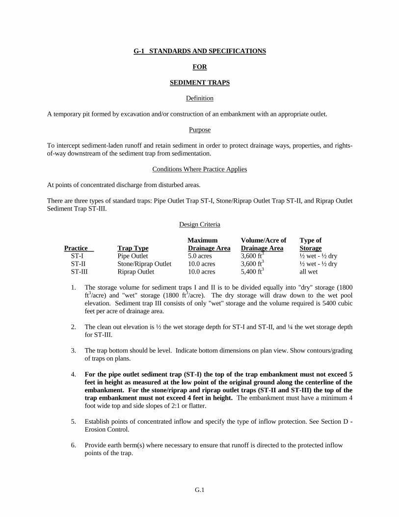
G.1
G-1 STANDARDS AND SPECIFICATIONS
FOR
SEDIMENT TRAPS
Definition
A temporary pit formed by excavation and/or construction of an embankment with an appropriate outlet.
Purpose
To intercept sediment-laden runoff and retain sediment in order to protect drainage ways, properties, and rights-
of-way downstream of the sediment trap from sedimentation.
Conditions Where Practice Applies
At points of concentrated discharge from disturbed areas.
There are three types of standard traps: Pipe Outlet Trap ST-I, Stone/Riprap Outlet Trap ST-II, and Riprap Outlet
Sediment Trap ST-III.
Design Criteria
Maximum Volume/Acre of Type of
Practice Trap Type Drainage Area Drainage Area Storage
ST-I Pipe Outlet 5.0 acres 3,600 ft3
½ wet - ½ dry
ST-II Stone/Riprap Outlet 10.0 acres 3,600 ft3
½ wet - ½ dry
ST-III Riprap Outlet 10.0 acres 5,400 ft3
all wet
1. The storage volume for sediment traps I and II is to be divided equally into "dry" storage (1800
ft3/acre) and "wet" storage (1800 ft
3/acre). The dry storage will draw down to the wet pool
elevation. Sediment trap III consists of only "wet" storage and the volume required is 5400 cubic
feet per acre of drainage area.
2. The clean out elevation is ½ the wet storage depth for ST-I and ST-II, and ¼ the wet storage depth
for ST-III.
3. The trap bottom should be level. Indicate bottom dimensions on plan view. Show contours/grading
of traps on plans.
4. For the pipe outlet sediment trap (ST-I) the top of the trap embankment must not exceed 5
feet in height as measured at the low point of the original ground along the centerline of the
embankment. For the stone/riprap and riprap outlet traps (ST-II and ST-III) the top of the
trap embankment must not exceed 4 feet in height. The embankment must have a minimum 4
foot wide top and side slopes of 2:1 or flatter.
5. Establish points of concentrated inflow and specify the type of inflow protection. See Section D -
Erosion Control.
6. Provide earth berm(s) where necessary to ensure that runoff is directed to the protected inflow points of the trap.

G.2
7. The top elevation of any dike directing water to a sediment trap is to be equal to, or higher than, the elevation of the trap embankment.
8. Interior slopes are to be 2:1 or flatter. 9. Locate inflow points to maximize the flow distance to the outlet. Where a 2:1 effective length to
width ratio between inflow and outflow cannot be obtained, baffles are required. See Detail G-2-4 Baffle Boards.
10. Locate sediment trap to ensure access for cleanout and disposal of the trapped sediment. 11. Locate sediment trap to discharge onto stable ground, stable channel, or into a storm drain
system. Discharge to a buffer may be required. Provide an outlet that conveys the discharge in a non-erosive manner to a stable area. Protect against scour at the discharge end of the spillway in accordance with the Section D-4 Outlet Protection.
12. Where discharge occurs at the property line, comply with local ordinances and drainage easement
requirements. 13. Do not locate trap any closer than 20 feet from an existing building foundation. Traps should not
be located in areas where the groundwater elevation is higher than the bottom of the trap. Sediment traps in structural fill areas (e.g., proposed roadways and building foundations) are discouraged. Upon removal, the wet soil around the trap must also be removed to facilitate compaction. The trap should be located to avoid conflicts with utilities.
14. Silt fence or other sediment control practices may be required during trap installation and removal. 15. Specify on the plan the type(s) of dewatering practice(s) to be used in accordance with Section F -
Dewatering.
Note: If any of the design criteria presented here cannot be met, see Section G-2 Sediment Basins.
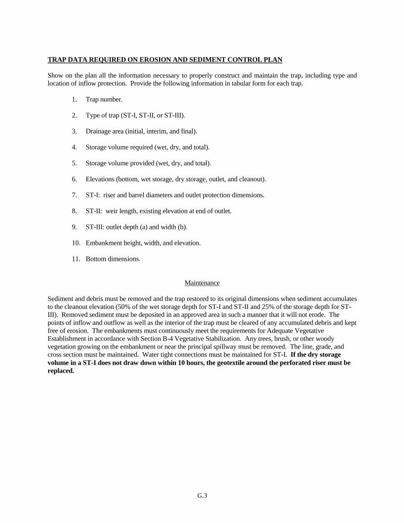
G.3
TRAP DATA REQUIRED ON EROSION AND SEDIMENT CONTROL PLAN
Show on the plan all the information necessary to properly construct and maintain the trap, including type and
location of inflow protection. Provide the following information in tabular form for each trap.
1. Trap number.
2. Type of trap (ST-I, ST-II, or ST-III).
3. Drainage area (initial, interim, and final).
4. Storage volume required (wet, dry, and total).
5. Storage volume provided (wet, dry, and total).
6. Elevations (bottom, wet storage, dry storage, outlet, and cleanout).
7. ST-I: riser and barrel diameters and outlet protection dimensions.
8. ST-II: weir length, existing elevation at end of outlet.
9. ST-III: outlet depth (a) and width (b).
10. Embankment height, width, and elevation.
11. Bottom dimensions.
Maintenance
Sediment and debris must be removed and the trap restored to its original dimensions when sediment accumulates
to the cleanout elevation (50% of the wet storage depth for ST-I and ST-II and 25% of the storage depth for ST-
III). Removed sediment must be deposited in an approved area in such a manner that it will not erode. The
points of inflow and outflow as well as the interior of the trap must be cleared of any accumulated debris and kept
free of erosion. The embankments must continuously meet the requirements for Adequate Vegetative
Establishment in accordance with Section B-4 Vegetative Stabilization. Any trees, brush, or other woody
vegetation growing on the embankment or near the principal spillway must be removed. The line, grade, and
cross section must be maintained. Water tight connections must be maintained for ST-I. If the dry storage
volume in a ST-I does not draw down within 10 hours, the geotextile around the perforated riser must be
replaced.
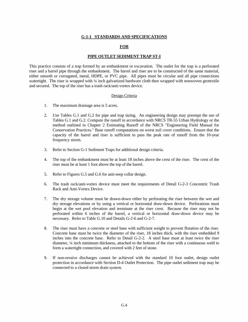
G.4
G-1-1 STANDARDS AND SPECIFICATIONS
FOR
PIPE OUTLET SEDIMENT TRAP ST-I
This practice consists of a trap formed by an embankment or excavation. The outlet for the trap is a perforated riser and a barrel pipe through the embankment. The barrel and riser are to be constructed of the same material, either smooth or corrugated, metal, HDPE, or PVC pipe. All pipes must be circular and all pipe connections watertight. The riser is wrapped with ¼ inch galvanized hardware cloth then wrapped with nonwoven geotextile and secured. The top of the riser has a trash rack/anti-vortex device.
Design Criteria
1. The maximum drainage area is 5 acres. 2. Use Tables G.1 and G.2 for pipe and trap sizing. An engineering design may preempt the use of
Tables G.1 and G.2. Compute the runoff in accordance with NRCS TR-55 Urban Hydrology or the method outlined in Chapter 2 Estimating Runoff of the NRCS "Engineering Field Manual for Conservation Practices." Base runoff computations on worst soil cover conditions. Ensure that the capacity of the barrel and riser is sufficient to pass the peak rate of runoff from the 10-year frequency storm.
3. Refer to Section G-1 Sediment Traps for additional design criteria. 4. The top of the embankment must be at least 18 inches above the crest of the riser. The crest of the
riser must be at least 1 foot above the top of the barrel. 5. Refer to Figures G.5 and G.6 for anti-seep collar design. 6. The trash rack/anti-vortex device must meet the requirements of Detail G-2-3 Concentric Trash
Rack and Anti-Vortex Device. 7. The dry storage volume must be drawn-down either by perforating the riser between the wet and
dry storage elevations or by using a vertical or horizontal draw-down device. Perforations must begin at the wet pool elevation and terminate at the riser crest. Because the riser may not be perforated within 6 inches of the barrel, a vertical or horizontal draw-down device may be necessary. Refer to Table G.10 and Details G-2-6 and G-2-7.
8. The riser must have a concrete or steel base with sufficient weight to prevent flotation of the riser.
Concrete base must be twice the diameter of the riser, 18 inches thick, with the riser embedded 9 inches into the concrete base. Refer to Detail G-2-2. A steel base must at least twice the riser diameter, ¼ inch minimum thickness, attached to the bottom of the riser with a continuous weld to form a watertight connection, and covered with 2 feet of stone.
9. If non-erosive discharges cannot be achieved with the standard 10 foot outlet, design outlet
protection in accordance with Section D-4 Outlet Protection. The pipe outlet sediment trap may be connected to a closed storm drain system.
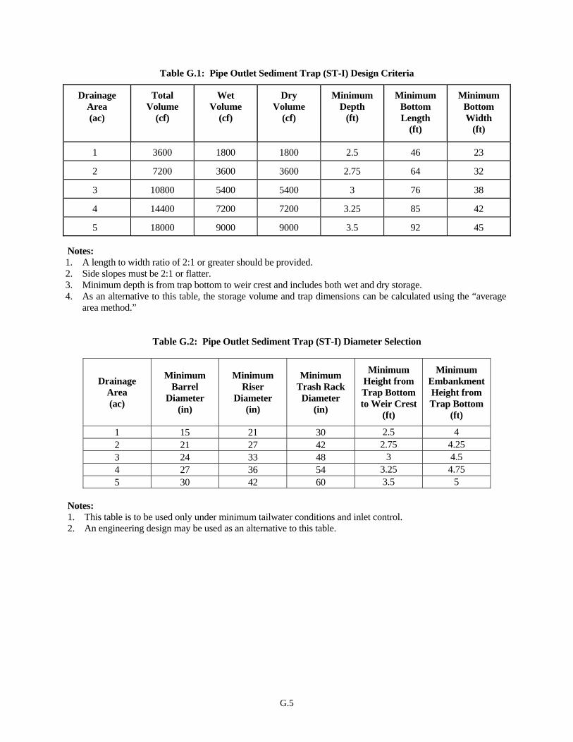
G.5
Table G.1: Pipe Outlet Sediment Trap (ST-I) Design Criteria
Drainage Area (ac)
Total Volume
(cf)
Wet Volume
(cf)
Dry Volume
(cf)
Minimum Depth
(ft)
Minimum Bottom Length
(ft)
Minimum Bottom Width
(ft)
1 3600 1800 1800 2.5 46 23
2 7200 3600 3600 2.75 64 32
3 10800 5400 5400 3 76 38
4 14400 7200 7200 3.25 85 42
5 18000 9000 9000 3.5 92 45 Notes: 1. A length to width ratio of 2:1 or greater should be provided. 2. Side slopes must be 2:1 or flatter. 3. Minimum depth is from trap bottom to weir crest and includes both wet and dry storage. 4. As an alternative to this table, the storage volume and trap dimensions can be calculated using the “average
area method.”
Table G.2: Pipe Outlet Sediment Trap (ST-I) Diameter Selection
Drainage Area (ac)
Minimum Barrel
Diameter (in)
Minimum Riser
Diameter (in)
Minimum Trash Rack
Diameter (in)
Minimum Height from Trap Bottom to Weir Crest
(ft)
Minimum Embankment Height from Trap Bottom
(ft)
1 15 21 30 2.5 4 2 21 27 42 2.75 4.25 3 24 33 48 3 4.5 4 27 36 54 3.25 4.75 5 30 42 60 3.5 5
Notes: 1. This table is to be used only under minimum tailwater conditions and inlet control. 2. An engineering design may be used as an alternative to this table.
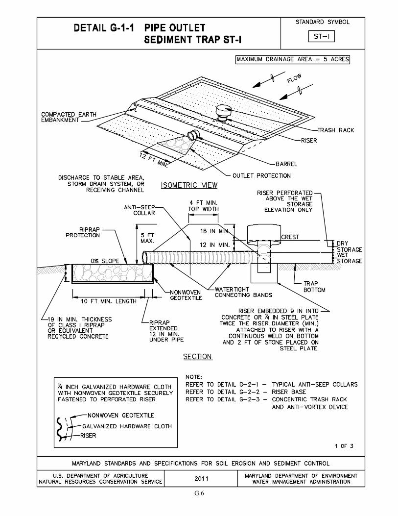
G.6

G.7
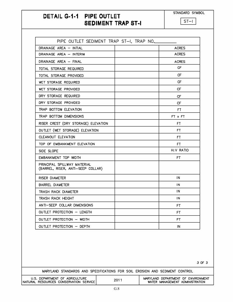
G.8
G.9
G-1-2 STANDARDS AND SPECIFICATIONS
FOR
STONE/RIPRAP OUTLET SEDIMENT TRAP ST-II
This practice consists of a trap formed by an excavation and an embankment with a partially excavated outlet
lined with riprap and containing a stone weir. The minimum length of the weir (in feet) is equal to four times the
drainage area (in acres). The weir crest is level and at least 1 foot below top of embankment and no more than 3
feet above existing ground beneath the outlet. The weir is constructed of 4 to 7 inch stone and the outlet of Class I
riprap. A one foot thick layer of ¾ to 1½ inch washed aggregate is placed on the upstream face of the outlet.
Design Criteria
1. The maximum drainage area is 10 acres.
2. The required total storage volume is calculated from the weir crest. For storage requirements see
Table G.3.
3. See Section G-1 Sediment Traps for additional design criteria.
4. If non-erosive discharges cannot be achieved with the standard 10 foot outlet, design outlet
protection in accordance with Section D-4 Outlet Protection.
5. The weir length (in feet) must be equal to, or greater than, four times the drainage area (in acres).
6. The weir crest must be at least one foot below the top of the embankment and no more than 3 feet
above existing ground (beneath the outlet).

G.10
Table G.3: Stone/Riprap Outlet Sediment Trap Design Criteria (ST-II)
Drainage
Area
(ac)
Total
Volume
(cf)
Wet
Volume
(cf)
Dry
Volume
(cf)
Minimum
Depth
(ft)
Minimum
Bottom
Length
(ft)
Minimum
Bottom
Width
(ft)
1 3600 1800 1800 2.5 46 23
2 7200 3600 3600 2.5 68 34
3 10800 5400 5400 2.5 86 42
4 14400 7200 7200 3.0 90 43
5 18000 9000 9000 3.0 101 50
6 21600 10800 10800 4.0 90 46
7 25200 12600 12600 4.0 100 50
8 28800 14400 14400 4.0 105 55
9 32400 16200 16200 4.0 110 60
10 36000 18000 18000 4.0 123 60
Notes:
1. Preferably, provide a length to width ratio of 2:1 or greater.
2. Side slopes must be 2:1 or flatter.
3. Minimum depth is from trap bottom to weir crest and includes both wet and dry storage.
4. Table is based on minimum weir length equal to 4 times the drainage area.
5. As an alternative to this table, the storage volume and trap dimensions can be calculated using the “average
area method.”
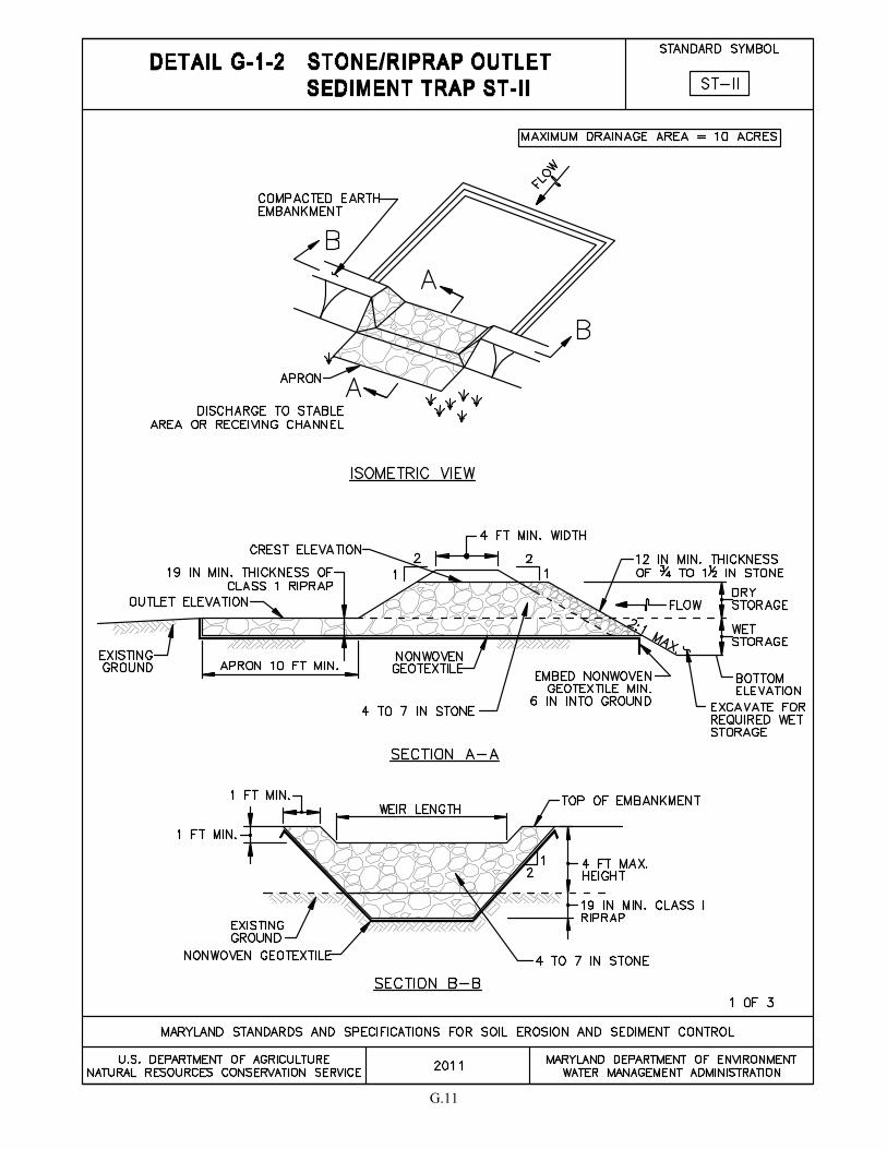
G.11

G.12

G.13

G.14
G-1-3 STANDARDS AND SPECIFICATIONS
FOR
RIPRAP OUTLET SEDIMENT TRAP ST-III
This practice consists of a trap formed by an excavation and an embankment with a partially excavated outlet
lined with riprap. Due to the configuration of the outfall, the required storage volume is all wet and equal to 5400
cubic feet per acre of drainage area.
Design Criteria
1. The maximum drainage area is 10 acres.
2. See Tables G.4 and G.5 for outlet and trap sizing.
3. The storage volume is calculated from the outlet invert.
4. See Section G-1 Sediment Traps for additional design criteria.
5. If non-erosive discharges cannot be achieved with the standard 10 foot outlet, design outlet
protection in accordance with Section D-4 Outlet Protection.
Table G.4: Riprap Outlet Sediment Trap (ST-III) Outlet Dimensions
Contributing
Drainage Area
(ac)
Depth of
Outlet (a)
(ft)
Bottom
Width of
Outlet (b)
(ft)
1 1.5 4.0
2 1.5 5.0
3 1.5 6.0
4 1.5 10.0
5 1.5 12.0
6 1.5 14.0
7 1.5 16.0
8 2.0 10.0
9 2.0 11.0
10 2.0 12.0
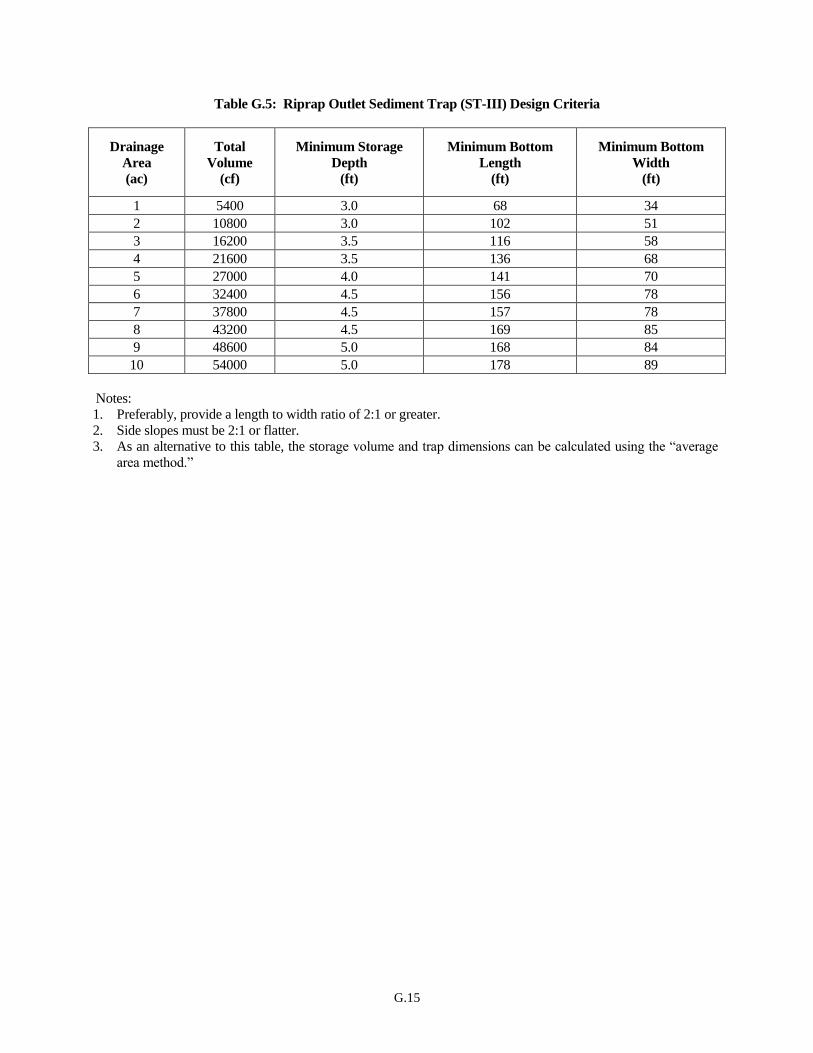
G.15
Table G.5: Riprap Outlet Sediment Trap (ST-III) Design Criteria
Drainage
Area
(ac)
Total
Volume
(cf)
Minimum Storage
Depth
(ft)
Minimum Bottom
Length
(ft)
Minimum Bottom
Width
(ft)
1 5400 3.0 68 34
2 10800 3.0 102 51
3 16200 3.5 116 58
4 21600 3.5 136 68
5 27000 4.0 141 70
6 32400 4.5 156 78
7 37800 4.5 157 78
8 43200 4.5 169 85
9 48600 5.0 168 84
10 54000 5.0 178 89
Notes:
1. Preferably, provide a length to width ratio of 2:1 or greater.
2. Side slopes must be 2:1 or flatter.
3. As an alternative to this table, the storage volume and trap dimensions can be calculated using the “average
area method.”

G.16
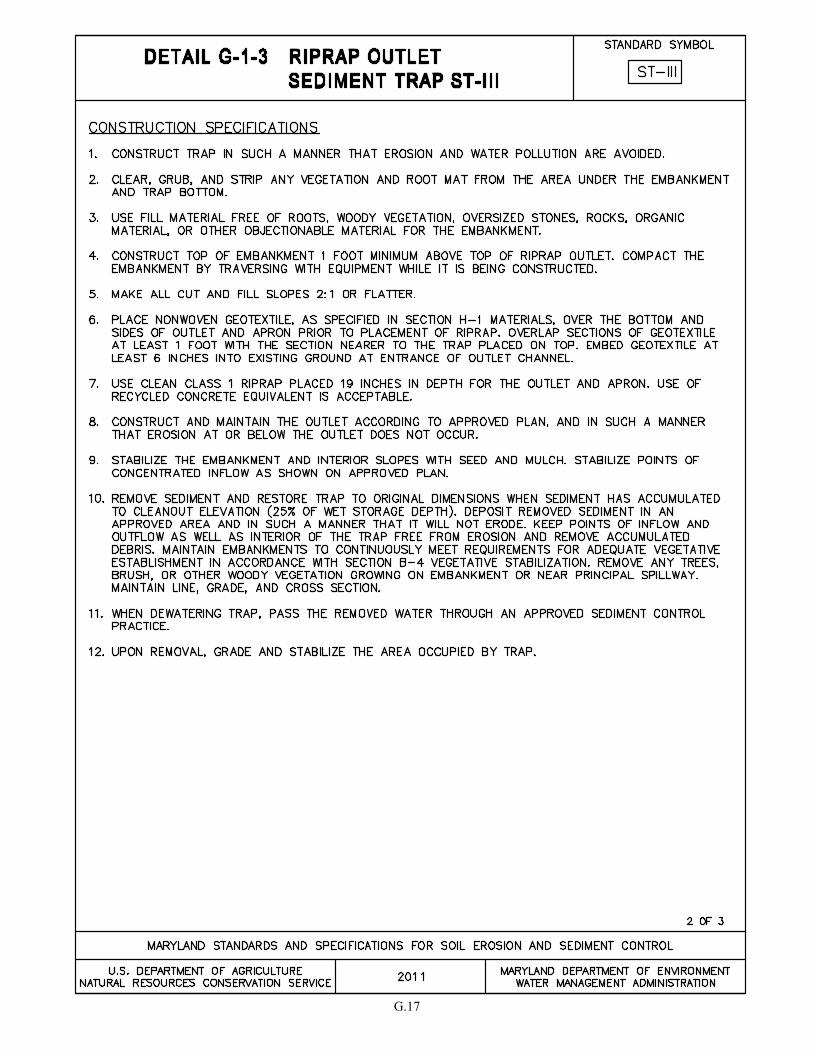
G.17
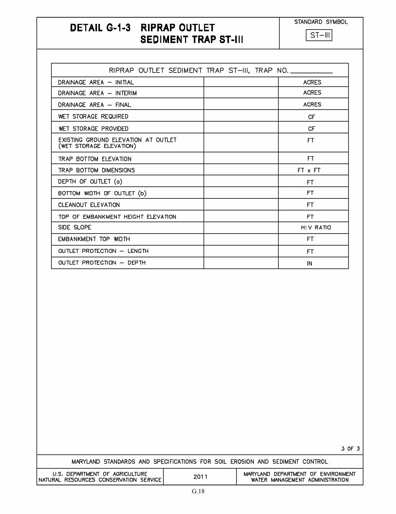
G.18

G.19
G-2 STANDARD AND SPECIFICATIONS
FOR
SEDIMENT BASINS
Definition
A temporary pond formed by excavation and/or construction of an embankment and equipped with a draw-
down device.
Purpose
To intercept sediment-laden runoff and retain sediment in order to protect drainage ways, properties, and rights-
of-way downstream of the sediment basin from sedimentation.
Conditions Where Practice Applies
A sediment basin is required where sediment trap drainage areas are exceeded. Stormwater management ponds
may be used as sediment basins provided they meet the requirements of this section and that the construction
sequence addresses converting the sediment basin to the permanent stormwater management pond.
Conditions of Use
This standard applies to the installation of temporary sediment basins on sites where:
1. Failure of the structure would not result in loss of life, damage to homes or buildings, or
interruption of use or service of public roads or utilities;
2. The drainage area does not exceed 100 acres;
3. The maximum embankment height does not exceed 15 feet measured from the natural ground to
the embankment top along the centerline of embankment; and
4. The basin is to be removed within 36 months after the beginning of construction of the basin.
Where any of these criteria cannot be met, the structure must be designed in accordance with Environmental
Article, Title 5, Subtitle 5, Annotated Code of Maryland or Natural Resource Conservation Service (NRCS)
Maryland Conservation Practice Standard Code No. 378 for Ponds.
Design Criteria
1. Local Requirements. In addition to the requirements herein, the design and construction must
comply with local laws, ordinances, rules and regulations.
2. Stormwater Management. Where a sediment basin is to be used as a permanent pond, the total
volume must be equal to or exceed the capacity requirements for the permanent pond or provisions
must be made for additional grading when the facility is converted to a permanent structure.
3. Location. Locate the basin to obtain the maximum storage benefit from the terrain and for ease of cleanout. The basin should be located to avoid conflicts with utilities and construction activities.
Where possible, locate so that storm drains may outfall or be diverted into the basin. Do not locate
G.20
basin any closer than 20 feet from an existing building foundation. Basins should not be located
in areas where the groundwater elevation is higher than the bottom of the basin. Basins in
structural fill areas (e.g., proposed roadways and building foundations) are discouraged.
4. Storage Volume. Provide at least 3600 cubic feet of storage for each acre of drainage. The volume
is measured from the bottom of the basin to the elevation of the principal spillway crest and is to be
divided equally into "dry" storage (1800 ft3/acre) and "wet" storage (1800 ft
3/acre). The dry storage
will draw down to the wet pool elevation. The 3600 cubic feet of storage is approximately equal to
1 inch of runoff per acre of drainage area.
5. Clean Out. The clean out elevation is one-half the wet storage depth. Determine and state the
elevation corresponding to the maximum allowable sediment level in the design data on the plans
as a distance below the top of the riser.
6. Surface Area. The ratio of surface area (acres) to discharge (cubic feet/second) must be greater
than or equal to 0.0035. The surface area is measured at the design high water elevation for the 10-
year frequency storm.
7. Inflow.
a. Establish points of concentrated inflow and specify the type of inflow protection. See Section D
- Erosion Control.
b. Locate inflow points to maximize the flow distance to the outlet. Length to width ratio must be
2:1 or greater, where length is the distance between the inlet and outlet. Where a 2:1 effective
length to width ratio between inflow and outflow cannot be obtained, baffles are required. See
Detail G-2-4 Baffle Boards.
c. Provide dikes/berms where necessary to ensure that runoff is directed to the protected inflow
points of the basin. The top elevation of any dike or berm directing water to a sediment basin
must be equal to, or higher than, the elevation of the basin embankment.
d. Specify in the sequence of construction that the basin must be constructed prior to the water
conveyances.
8. Drawings. Contours for basin grading must be shown on the plan. A profile and cross-section of
the spillway(s) and details for all appurtenances must be provided. Include bottom, wet storage,
dry storage, and cleanout elevations; dimensions of outlet protection; and embankment width and
elevation.
9. Cut-Off Trench. Provide for a cut-off trench along the centerline of the proposed embankment, a
minimum depth of 4 feet and a bottom width (minimum 4 feet) wide enough to permit operation of
excavation and compaction equipment. The cut-off trench must be excavated with side slopes 1:1
or flatter and be continuous for the entire length of proposed embankment.
10. Impervious Core. Provide an impervious core with a minimum top width of 4 feet along the
centerline of the proposed embankment. Impervious core must be continuous throughout the
embankment and must extend upwards with 1:1 side slopes the from the cut-off trench up to the 10-
year water surface elevation.
11. Embankment. Elevations of the top of earth fill at constructed and settled height of the embankment must be shown on the profile. The top of the dam embankment is to be level. The
top width must be a minimum of 8 feet for embankments up to 10 feet in height. For embankments
G.21
between 10 feet and 15 feet in height, the minimum top width is 10 feet. The combined upstream
and downstream side slopes of the embankment must have a combined total of five horizontal to
one vertical (5:1) minimum with neither slope steeper than two horizontal to one vertical (2:1).
12. Hydrologic Analysis. Compute the runoff in accordance with NRCS TR-55 Urban Hydrology or
the method outlined in Chapter 2 Estimating Runoff of the NRCS "Engineering Field Manual for
Conservation Practices." Base runoff computations on “worst soil cover” conditions. Ensure that
the combined capacities of the principal and emergency spillways are sufficient to pass the "routed"
peak rate of runoff from the 10-year frequency storm. The start elevation for routing must
correspond to the wet pool elevation (i.e. wet storage volume must not be included in the
analysis).
13. Draw-Down Device. The dry storage volume is to be dewatered to the wet pool elevation over a
10 hour period. This can be done by constructing a perforated horizontal or vertical draw-down
device with an orifice to control discharge. Use the chart or equations in Table G.10 to determine
the appropriate orifice size. Design the pipe perforations so that the total area of the perforations is
equal to or greater than 4 times the area of the control orifice. Alternate draw-down methods may
be designed as allowed by the appropriate approval authority.
14. Outlet. Locate basin to discharge onto stable ground, stable channel, or into a storm drain
system. Discharge to a buffer may be required. Provide an outlet that conveys the discharge in a
non-erosive manner to a stable area. Protect against scour at the discharge end of the pipe spillway
in accordance with the Section D-4 Outlet Protection.
15. Drainage Easements. Where discharge occurs at the property line, comply with local ordinances
and drainage easement requirements. Show adequate notes and references concerning the
easements on the erosion and sediment control plan.
16. Emergency Spillway. An emergency spillway is required when the principal spillway is not
designed to pass the 10-year frequency storm. The entire flow area of the emergency spillway
must be in existing ground (not fill). The control section is to be trapezoidal with a minimum
bottom width of eight feet and have a straight, level length of at least 25 feet. The outlet section
should have sufficient slope such that the discharge capacity of the spillway is not restricted and
allows the discharge to be released at a non-erosive velocity.
a. The minimum capacity of the emergency spillway must pass the peak rate of runoff from the 10-
year frequency storm, less any reduction due to flow in the principal spillway. Determine the
emergency spillway dimensions by using Figure G.3 Emergency Spillway Design and Table G.9
or Figure G.4.
b. The velocity of flow in the exit channel must not exceed 5 feet per second for vegetated
channels. For channels with erosion protection other than vegetation, ensure velocities are
within the non-erosive range for the type of protection used.
c. Freeboard (elevation difference between the 10-year storm water surface in the emergency
spillway and the top of the settled embankment) must be at least a minimum of one (1) foot.
Where no emergency spillway is provided, design the freeboard to a minimum of two (2) feet.
d. The principal spillway crest elevation must be a minimum of one (1) foot below the elevation of
the control section of the emergency spillway.
17. Principal Spillway. Provide a principal spillway which consists of a vertical pipe or concrete box
(riser) joined to a pipe (barrel) that extends through the embankment and discharges beyond the
G.22
downstream toe of the fill.
18. Riser and Barrel Assembly.
a. The barrel must pass at least 10 percent of the 10-year, 24-hour frequency storm and be at least
10 inches in diameter. If the principal spillway is designed to pass the entire 10-year storm, then
the barrel must have a minimum cross-sectional area of three (3) square feet.
b. The design of the barrel should be based on Table G.7, Table G.8, or hydraulic calculations.
For plastic pipe, Table G.7 can be used for corrugated lined pipe and Table G.8 for smooth
lined pipe. Use manufacturer specification for loading.
c. Pipe material must conform to NRCS Maryland Conservation Practice Standard Code No. 378
for Ponds.
d. An anti-vortex device and trash rack are required for all risers. For corrugated metal pipe risers,
meet the specifications in Detail G-2-3 Concentric Trash Rack and Anti-Vortex Device. For
other types of risers, refer to NRCS Maryland Conservation Practice Standard Code No. 378 for
Ponds.
e. The riser must include a base of sufficient weight to prevent flotation of the riser. Concrete
riser bases must be at least twice the diameter of the riser, a minimum of 18 inches thick, and
contain steel reinforcement as shown in Detail G-2-2 Corrugated Riser Base. The riser needs to
be embedded 9 inch minimum into the base. Anti-flotation calculations must be provided for
risers over 10 feet in height, based on the following:
i. Analyze the riser for flotation, assuming all orifices and pipes are plugged.
ii. Provide a factor of safety of 1.2 or greater. (Downward forces ≥ 1.2 x upward forces.)
f. Precast concrete structures must include details for a projection collar. If the riser contains
multiple sections, provide a mechanical connection at each joint as shown on Detail G-2-8
Precast Riser Connector to prevent joint separation which may be caused by differential earth
pressures in the embankment.
g. To prevent piping along the barrel, include a filter diaphragm or anti-seep collars around the
barrel. Anti-seep collars may not be acceptable on permanent structures. For filter diaphragm
design refer to NRCS Part 628 Dams, National Engineering Handbook, Chapter 45. Anti-seep
collars are to be designed according to Figures G.5 and G.6.
19. Removal of Basin.
a. Specify on the plan the type(s) of dewatering device(s) to be used in accordance with Section F
- Dewatering.
b. The location and disposal method(s) for sediment removed from a basin must be shown on the
plans. Do not deposit the sediment downstream from the basin or adjacent to a drainage way or
floodplain. Off-site disposal sites must be covered by an approved erosion and sediment
control plan.
c. Silt fence or other sediment control practices may be required during basin installation and
removal.
d. Upon removal, the wet soil around the basin must also be removed to facilitate compaction.

G.23
Maintenance
Sediment and debris must be removed and the basin restored to its original dimensions when sediment
accumulates to the cleanout elevation (50% of the wet storage depth). Removed sediment must be deposited in
an approved area in such a manner that it will not erode. The points of inflow and outflow as well as the interior
of the basin must be cleared of any accumulated debris and kept free of erosion. The embankments must
continuously meet the requirements for Adequate Vegetative Establishment in accordance with Section B-4
Vegetative Stabilization. Any trees, brush, or other woody vegetation growing on the embankment or near the
principal spillway must be removed. The line, grade, and cross section must be maintained. Water tight
connections must be maintained. If the dry storage volume does not drain within 10 hours, the geotextile
around the draw-down device must be replaced.
G.24
BASIN DATA REQUIRED ON EROSION AND SEDIMENT CONTROL PLAN
Show on the plan all the information necessary to properly construct and maintain the basin, including type and
location of inflow protection. Additionally, the plan must show the controls necessary for the installation of the
basin. At a minimum provide the following information for each basin:
1. Basin number(s).
2. Plan view of the basin and emergency spillway showing existing and proposed contours.
3. Drainage area acreage (initial, interim, final).
4. Storage computations:
a. Total volume required including volumes of "wet" and "dry" storage.
b. Total volume provided including volumes of "wet" and "dry" storage.
c. Level of sediment at which cleanout shall be required, stated as a distance from the riser crest
to the sediment surface.
5. Cross-section of embankment including constructed and settled top elevations, side slopes, cutoff
trench dimensions, and profile of the principal spillway.
6. Principal spillway information: riser and barrel diameters and material, inverts, orifices, trash rack,
weir elevations, projection collar, filter diaphragm or anti-seep collar size and spacing, and other
relevant information.
7. Maintenance equipment access points.
8. Dewatering method (removable pumping station, etc.).
9. Drawdown device information.
10. Inflow and outlet protection dimensions.
11. Profile and cross-section of the emergency spillway.
12. Details of pipe connections, riser base, seepage control (e.g. filter diaphragm or anti-seep collars),
trash rack, cleanout elevation, and anti-vortex device.
13. Drainage area map clearly showing the maximum contributory drainage area to the basin.
14. Construction Specifications (refer to following page).
15. Other information as required by the approval agency.
NOTE: A Temporary Sediment Basin Design Data Sheet (Table G.6) must be submitted for each sediment
basin.
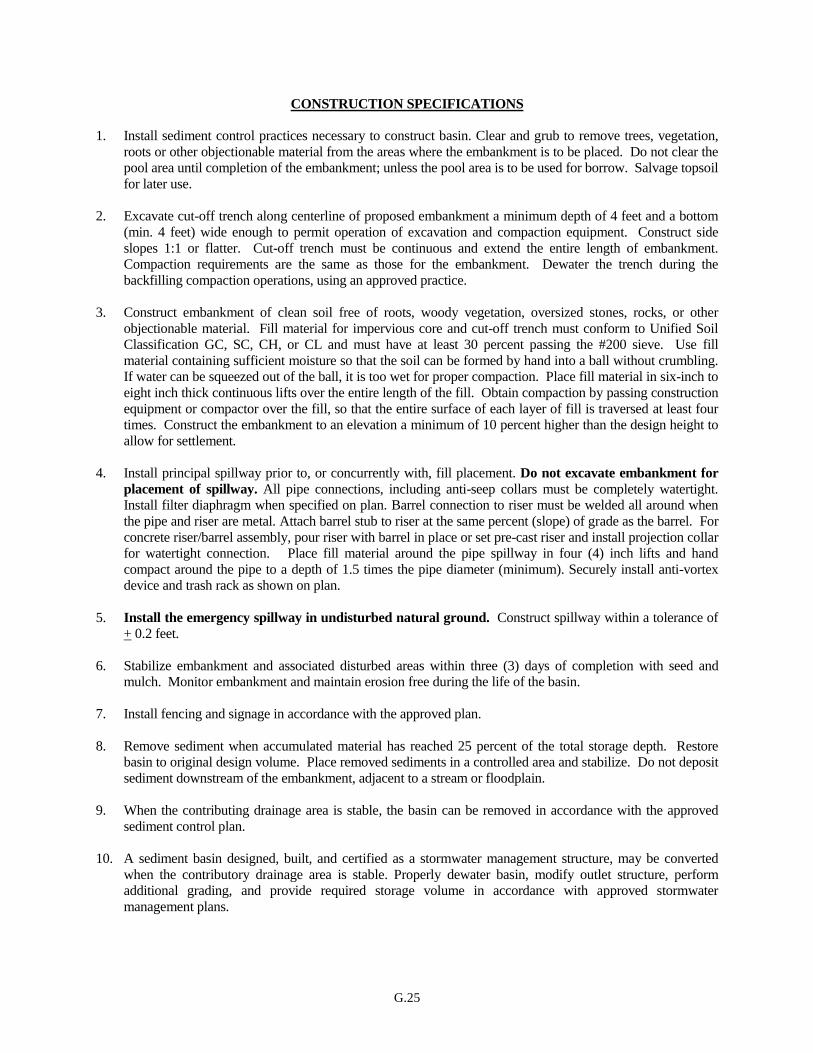
G.25
CONSTRUCTION SPECIFICATIONS
1. Install sediment control practices necessary to construct basin. Clear and grub to remove trees, vegetation,
roots or other objectionable material from the areas where the embankment is to be placed. Do not clear the
pool area until completion of the embankment; unless the pool area is to be used for borrow. Salvage topsoil
for later use.
2. Excavate cut-off trench along centerline of proposed embankment a minimum depth of 4 feet and a bottom
(min. 4 feet) wide enough to permit operation of excavation and compaction equipment. Construct side
slopes 1:1 or flatter. Cut-off trench must be continuous and extend the entire length of embankment.
Compaction requirements are the same as those for the embankment. Dewater the trench during the
backfilling compaction operations, using an approved practice.
3. Construct embankment of clean soil free of roots, woody vegetation, oversized stones, rocks, or other
objectionable material. Fill material for impervious core and cut-off trench must conform to Unified Soil
Classification GC, SC, CH, or CL and must have at least 30 percent passing the #200 sieve. Use fill
material containing sufficient moisture so that the soil can be formed by hand into a ball without crumbling.
If water can be squeezed out of the ball, it is too wet for proper compaction. Place fill material in six-inch to
eight inch thick continuous lifts over the entire length of the fill. Obtain compaction by passing construction
equipment or compactor over the fill, so that the entire surface of each layer of fill is traversed at least four
times. Construct the embankment to an elevation a minimum of 10 percent higher than the design height to
allow for settlement.
4. Install principal spillway prior to, or concurrently with, fill placement. Do not excavate embankment for
placement of spillway. All pipe connections, including anti-seep collars must be completely watertight.
Install filter diaphragm when specified on plan. Barrel connection to riser must be welded all around when
the pipe and riser are metal. Attach barrel stub to riser at the same percent (slope) of grade as the barrel. For
concrete riser/barrel assembly, pour riser with barrel in place or set pre-cast riser and install projection collar
for watertight connection. Place fill material around the pipe spillway in four (4) inch lifts and hand
compact around the pipe to a depth of 1.5 times the pipe diameter (minimum). Securely install anti-vortex
device and trash rack as shown on plan.
5. Install the emergency spillway in undisturbed natural ground. Construct spillway within a tolerance of
+ 0.2 feet.
6. Stabilize embankment and associated disturbed areas within three (3) days of completion with seed and
mulch. Monitor embankment and maintain erosion free during the life of the basin.
7. Install fencing and signage in accordance with the approved plan.
8. Remove sediment when accumulated material has reached 25 percent of the total storage depth. Restore
basin to original design volume. Place removed sediments in a controlled area and stabilize. Do not deposit
sediment downstream of the embankment, adjacent to a stream or floodplain.
9. When the contributing drainage area is stable, the basin can be removed in accordance with the approved
sediment control plan.
10. A sediment basin designed, built, and certified as a stormwater management structure, may be converted
when the contributory drainage area is stable. Properly dewater basin, modify outlet structure, perform
additional grading, and provide required storage volume in accordance with approved stormwater
management plans.
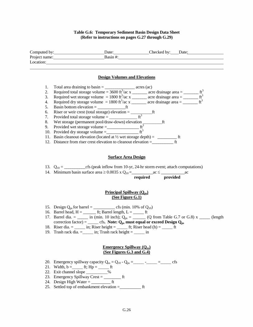
G.26
Table G.6: Temporary Sediment Basin Design Data Sheet
(Refer to instructions on pages G.27 through G.29)
Computed by: Date: Checked by: Date:
Project name: Basin #:
Location:
Design Volumes and Elevations
1. Total area draining to basin = ______________ acres (ac)
2. Required total storage volume = 3600 ft3/ac x _______ acre drainage area = _______ ft
3
3. Required wet storage volume = 1800 ft3/ac x _______ acre drainage area = _______ ft
3
4. Required dry storage volume = 1800 ft3/ac x _______ acre drainage area = _______ ft
3
5. Basin bottom elevation = _____________ft
6. Riser or weir crest (total storage) elevation = __________ft
7. Provided total storage volume = _____________ ft3
8. Wet storage (permanent pool/draw-down) elevation _________ft
9. Provided wet storage volume =_______________ ft3
10. Provided dry storage volume =_______________ ft3
11. Basin cleanout elevation (located at ½ wet storage depth) = _________ ft
12. Distance from riser crest elevation to cleanout elevation =__________ ft
Surface Area Design
13. Q10 = __________cfs (peak inflow from 10-yr, 24-hr storm event; attach computations)
14. Minimum basin surface area 0.0035 x Q10 =__________ac ___________ac
required provided
Principal Spillway (Qps)
(See Figure G.1)
15. Design Qps for barrel = __________ cfs (min. 10% of Q10)
16. Barrel head, H = ______ ft; Barrel length, L = _____ ft
17. Barrel dia. = _____ in (min. 10 inch); Qps = ______ (Q from Table G.7 or G.8) x _____ (length
correction factor) = _____ cfs. Note: Qps must equal or exceed Design Qps
18. Riser dia. = _____ in; Riser height = _____ ft; Riser head (h) = _____ ft
19. Trash rack dia. =_____ in; Trash rack height = _____ in
Emergency Spillway (Qes)
(See Figures G.3 and G.4)
20. Emergency spillway capacity Qes = Q10 - Qps =_____ -_____ =_____ cfs
21. Width, b =_____ ft; Hp = _____ ft
22. Exit channel slope __________%
23. Emergency Spillway Crest = ________ ft
24. Design High Water = _________ ft 25. Settled top of embankment elevation =__________ ft
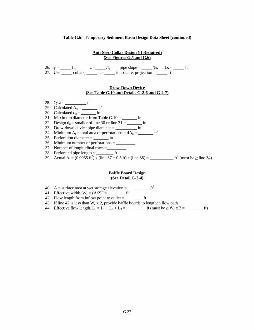
G.27
Table G.6: Temporary Sediment Basin Design Data Sheet (continued)
Anti-Seep Collar Design (If Required)
(See Figures G.5 and G.6)
26. y = _____ ft; z =_____:1; pipe slope = _____ %; Ls = _____ ft
27. Use _____ collars, _____ ft - _____ in. square; projection = _____ ft
Draw-Down Device
(See Table G.10 and Details G-2-6 and G-2-7)
28. Qd-d = __________ cfs
29. Calculated Ao = _______ ft2
30. Calculated do = _______ in
31. Maximum diameter from Table G.10 = _______ in
32. Design do = smaller of line 30 or line 31 = _______ in
33. Draw-down device pipe diameter = __________ in
34. Minimum At = total area of perforations = 4Ao = _______ ft2
35. Perforation diameter = _______ in
36. Minimum number of perforations = _________
37. Number of longitudinal rows =_________
38. Perforated pipe length = ________ ft
39. Actual At = (0.0055 ft2) x (line 37 ÷ 0.5 ft) x (line 38) = ___________ ft
2 (must be ≥ line 34)
Baffle Board Design
(See Detail G-2-4)
40. A = surface area at wet storage elevation = __________ ft2
41. Effective width, We = (A/2)½
= ________ ft
42. Flow length from inflow point to outlet = ________ ft
43. If line 42 is less than We x 2, provide baffle boards to lengthen flow path
44. Effective flow length, Le = L1 + L2 + L3 = _________ ft (must be ≥ We x 2 = ________ ft)
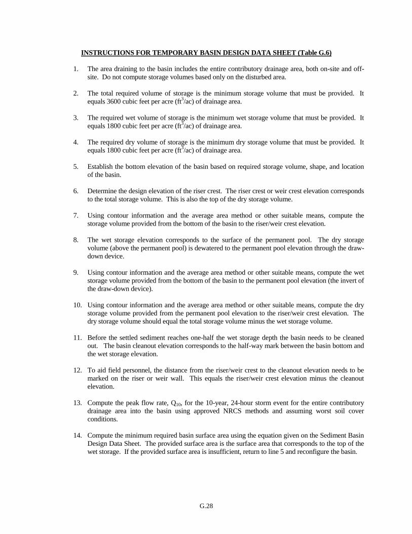
G.28
INSTRUCTIONS FOR TEMPORARY BASIN DESIGN DATA SHEET (Table G.6)
1. The area draining to the basin includes the entire contributory drainage area, both on-site and off-
site. Do not compute storage volumes based only on the disturbed area.
2. The total required volume of storage is the minimum storage volume that must be provided. It
equals 3600 cubic feet per acre (ft3/ac) of drainage area.
3. The required wet volume of storage is the minimum wet storage volume that must be provided. It
equals 1800 cubic feet per acre (ft3/ac) of drainage area.
4. The required dry volume of storage is the minimum dry storage volume that must be provided. It
equals 1800 cubic feet per acre (ft3/ac) of drainage area.
5. Establish the bottom elevation of the basin based on required storage volume, shape, and location
of the basin.
6. Determine the design elevation of the riser crest. The riser crest or weir crest elevation corresponds
to the total storage volume. This is also the top of the dry storage volume.
7. Using contour information and the average area method or other suitable means, compute the
storage volume provided from the bottom of the basin to the riser/weir crest elevation.
8. The wet storage elevation corresponds to the surface of the permanent pool. The dry storage
volume (above the permanent pool) is dewatered to the permanent pool elevation through the draw-
down device.
9. Using contour information and the average area method or other suitable means, compute the wet
storage volume provided from the bottom of the basin to the permanent pool elevation (the invert of
the draw-down device).
10. Using contour information and the average area method or other suitable means, compute the dry
storage volume provided from the permanent pool elevation to the riser/weir crest elevation. The
dry storage volume should equal the total storage volume minus the wet storage volume.
11. Before the settled sediment reaches one-half the wet storage depth the basin needs to be cleaned
out. The basin cleanout elevation corresponds to the half-way mark between the basin bottom and
the wet storage elevation.
12. To aid field personnel, the distance from the riser/weir crest to the cleanout elevation needs to be
marked on the riser or weir wall. This equals the riser/weir crest elevation minus the cleanout
elevation.
13. Compute the peak flow rate, Q10, for the 10-year, 24-hour storm event for the entire contributory
drainage area into the basin using approved NRCS methods and assuming worst soil cover
conditions.
14. Compute the minimum required basin surface area using the equation given on the Sediment Basin
Design Data Sheet. The provided surface area is the surface area that corresponds to the top of the
wet storage. If the provided surface area is insufficient, return to line 5 and reconfigure the basin.

G.29
15. Design the principal spillway to have a minimum discharge capacity equal to 10 percent of Q10 or
the flow rate through a 10 inch pipe, whichever is greater. Note: If there is no emergency spillway
then Qps = Q10.
16. Based on the storage volume, the topography in and around the basin, and Figure G.1, determine L,
the length of the barrel, and H, the distance between the centerline of the outlet pipe and the design
high water elevation for Q10.
17. Using Table G.7 or G.8, determine the barrel diameter corresponding to H and Qps. For pipe
lengths other than 70 feet, adjust the flow rates using the correction factors provided. The barrel
must be at least 10 inches in diameter. If the principal spillway is designed to pass Q10, a minimum
cross-sectional area of 3 ft2 is required.
18. Determine the riser diameter, height, and "h" to release the principal spillway discharge using the
solid lines on Figure G.2. (Note that "H" on Figure G.2 corresponds to "h" on Figure G.1.) Set the
riser crest 1 foot (minimum) below the emergency spillway (See Figure G.1).
19. Determine the trash rack and anti-vortex device size using Detail G-2-3, Concentric Trash Rack
and Anti-Vortex Device.
20. Compute the capacity required for the emergency spillway, Qes, by subtracting the actual flow
carried by the principal spillway from Q10.
21. Using Table G.9, Figure G.3, and Figure G.4, determine values of Hp and bottom width for the
emergency spillway.
22. Determine the exit channel slope.
23. Determine the design elevation of the emergency spillway crest.
24. Design high water is the elevation of the emergency spillway crest plus the value of Hp. If there is
not a separate emergency spillway, add Hp to the principal spillway crest. (This elevation also
corresponds to the barrel head from line 16.)
25. The settled constructed top of embankment requires a 1.0 foot minimum of freeboard above design
high water. To allow for settlement design the top of dam elevation to include a minimum 10
percent increase in height.
26. Refer to Figure G.5 Anti-Seep Collar Design.
27. Refer to the Instruction Sheet for Designing Anti-Seep Collars (page G.39) and Figure G.6 to
determine the size and number of anti-seep collars.
28. Calculate Qd-d using the equation provided with Table G.10 Draw-Down Device Orifice Sizing.
Qd-d is the average flow rate required to drain the dry storage volume in 10 hours.
29. Calculate Ao using the equation provided with Table G.10.
30. Calculate do using the equation provided with Table G.10.
31. Based on drainage area (line 1), read the corresponding Maximum Internal Orifice Diameter do from Table G.10.

G.30
32. The design internal orifice diameter is the smaller of line 31 or line 32. The size of the internal
orifice governs the discharge between the riser crest and permanent pool elevations, with the draw-
down time being 10 hours (minimum).
33. The diameter of the pipe used for the draw-down device must meet the minimum pipe diameter
corresponding to the respective orifice diameter, as listed in Table G.10.
34. Calculate the minimum required perforation area. It equals four times the internal orifice area.
35. Decide on the diameter of the perforations. The recommended perforation diameter is 1 inch
(0.0055 ft2 area).
36. Divide line 34 by the perforation area (use 0.0055 ft2 for 1 inch perforations).
37. Determine the number of longitudinal rows based on pipe diameter and as close to 6 inch spacing
as possible between rows. For example, an 8 inch diameter pipe (25.1 inch circumference) would
have 4 rows of perforations running the length of the pipe. Perforation spacing along the length of
the pipe should also be 6 inches.
Note: If the length of the draw-down device exceeds a reasonable length, consider using a multiple
pipe configuration or reducing the perforation spacing. Any deviations from the standard detail
must be indicated clearly on the plans.
38. Determine the length of perforated pipe required to provide sufficient perforations so that the total
area of perforations is greater than, or equal to, four times the internal orifice area. For 1 inch
diameter holes and 6 inch spacing, L ≥ (4Ao)(0.5ft)/(0.0055 ft2)(number of rows).
39. Check that the total provided perforation area exceeds the minimum required perforation area. The
numbers provided in step 38 are based on 1 inch perforations spaced 6 inches apart. Total area of
perforations = (area of each perforation) x (number of perforations/foot of pipe) x (length of
perforated section).
40. This is the provided surface area from line 14, converted to square feet. It corresponds to the area
at the top of the wet storage elevation.
41. The effective width is the width the basin would have if it had a length: width ratio equal to 2:1.
Calculate the effective width using the equation We = (A/2)0.5
.
42. Measure the distance from the inflow point to the outlet. If there is more than one inflow point,
calculate the length separately for each point.
43. Baffles are required when the distance between the inflow and outflow points is less than twice the
effective width (We).
44. Locate and size baffles so the flow path from the inflow point around the baffles to the riser
exceeds 2 x We.
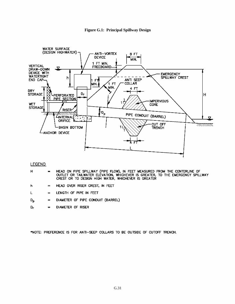
G.31
Figure G.1: Principal Spillway Design
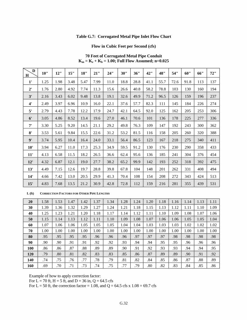
G.32
Table G.7: Corrugated Metal Pipe Inlet Flow Chart
Flow in Cubic Feet per Second (cfs)
70 Feet of Corrugated Metal Pipe Conduit
Km = Ke + Kb = 1.00; Full Flow Assumed; n=0.025
D 10" 12" 15" 18" 21" 24" 30" 36" 42" 48" 54" 60" 66" 72"
H
1' 1.25 1.98 3.48 5.47 7.99 11.0 18.8 28.8 41.1 55.7 72.6 91.8 113 137
2' 1.76 2.80 4.92 7.74 11.3 15.6 26.6 40.8 58.2 78.8 103 130 160 194
3' 2.16 3.43 6.02 9.48 13.8 19.1 32.6 49.9 71.2 96.5 126 159 196 237
4' 2.49 3.97 6.96 10.9 16.0 22.1 37.6 57.7 82.3 111 145 184 226 274
5' 2.79 4.43 7.78 12.2 17.9 24.7 42.1 64.5 92.0 125 162 205 253 306
6' 3.05 4.86 8.52 13.4 19.6 27.0 46.1 70.6 101 136 178 225 277 336
7' 3.30 5.25 9.20 14.5 21.1 29.2 49.8 76.3 109 147 192 243 300 362
8' 3.53 5.61 9.84 15.5 22.6 31.2 53.2 81.5 116 158 205 260 320 388
9' 3.74 5.95 10.4 16.4 24.0 33.1 56.4 86.5 123 167 218 275 340 411
10' 3.94 6.27 11.0 17.3 25.3 34.9 59.5 91.2 130 176 230 290 358 433
11' 4.13 6.58 11.5 18.2 26.5 36.6 62.4 95.6 136 185 241 304 376 454
12' 4.32 6.87 12.1 19.0 27.7 38.2 65.2 99.9 142 193 252 318 392 475
13' 4.49 7.15 12.6 19.7 28.8 39.8 67.8 104 148 201 262 331 408 494
14' 4.66 7.42 13.0 20.5 29.9 41.3 70.4 108 154 208 272 343 424 513
15' 4.83 7.68 13.5 21.2 30.9 42.8 72.8 112 159 216 281 355 439 531
L (ft) CORRECTION FACTORS FOR OTHER PIPE LENGTHS
20 1.58 1.53 1.47 1.42 1.37 1.34 1.28 1.24 1.20 1.18 1.16 1.14 1.13 1.11
30 1.39 1.36 1.32 1.29 1.27 1.24 1.21 1.18 1.15 1.13 1.12 1.11 1.10 1.09
40 1.25 1.23 1.21 1.20 1.18 1.17 1.14 1.12 1.11 1.10 1.09 1.08 1.07 1.06
50 1.15 1.14 1.13 1.12 1.11 1.10 1.09 1.08 1.07 1.06 1.06 1.05 1.05 1.04
60 1.07 1.06 1.06 1.05 1.05 1.05 1.04 1.04 1.03 1.03 1.03 1.02 1.02 1.02
70 1.00 1.00 1.00 1.00 1.00 1.00 1.00 1.00 1.00 1.00 1.00 1.00 1.00 1.00
80 .95 .95 .95 .95 .96 .96 .96 .97 .97 .97 .98 .98 .98 .98
90 .90 .90 .91 .91 .92 .92 .93 .94 .94 .95 .95 .96 .96 .96
100 .86 .86 .87 .88 .89 .89 .90 .91 .92 .93 .93 .94 .94 .95
120 .79 .80 .81 .82 .83 .83 .85 .86 .87 .89 .89 .90 .91 .92
140 .74 .75 .76 .77 .78 .79 .81 .82 .84 .85 .86 .87 .88 .89
160 .69 .70 .71 .73 .74 .75 .77 .79 .80 .82 .83 .84 .85 .86
Example of how to apply correction factor:
For L = 70 ft, H = 5 ft, and D = 36 in, Q = 64.5 cfs
For L = 50 ft, the correction factor = 1.08, and Q = 64.5 cfs x 1.08 = 69.7 cfs

G.33
Table G.8: Reinforced Concrete Pipe Inlet Flow Chart
Flow in Cubic Feet per Second (cfs)
70 Feet of Reinforced Concrete Pipe Conduit
Km = Ke + Kb = 1.00; Full Flow Assumed; n=0.013
D
12” 15” 18” 21” 24” 30” 36” 42” 48” 54” 60” 66” 72” 78” 84” 90” 96” 102”
H
1' 3.08 5.17 7.83 11.1 14.9 24.2 35.8 49.7 65.8 84.2 105 128 153 180 210 242 276 312
2' 4.35 7.31 11.1 15.7 21.0 34.2 50.6 70.3 93.1 119 148 181 216 255 297 342 390 441
3' 5.33 8.95 13.6 19.2 25.8 41.9 62.0 86.1 114 146 182 221 265 312 363 419 478 541
4' 6.15 10.3 15.7 22.1 29.8 48.4 71.6 99.4 132 168 210 255 306 360 420 483 552 624
5' 6.88 11.6 17.5 24.7 33.3 54.1 80.1 111 147 188 234 286 342 403 469 540 617 698
6' 7.54 12.7 19.2 27.1 36.4 59.3 87.7 122 161 206 257 313 374 441 514 592 676 765
7' 8.14 13.7 20.7 29.3 39.4 64.0 94.8 131 174 223 277 338 404 477 555 640 730 826
8' 8.70 14.6 22.2 31.3 42.1 68.5 101 141 186 238 297 361 432 510 594 684 780 883
9' 9.23 15.5 23.5 33.2 44.6 72.6 107 149 197 253 315 383 459 541 630 725 827 936
10' 9.73 16.3 24.8 35.0 47.0 76.5 113 157 208 266 332 404 483 570 664 764 872 987
11' 10.2 17.1 26.0 36.7 49.3 80.3 119 165 218 279 348 424 507 598 696 802 915
1
1035
12' 10.7 17.9 27.1 38.3 51.5 83.9 124 172 228 292 363 442 530 624 727 837 955
5
1081
13' 11.1 18.6 28.2 39.9 53.6 87.3 129 179 237 304 378 461 551 650 757 872 994
8
1125
14' 11.5 19.3 29.3 41.4 55.7 90.6 134 186 246 315 392 478 572 674 785 904 103
2
1168
15' 11.9 20.0 30.3 42.9 57.6 93.8 139 192 255 326 406 495 592 698 813 936
4
106
8
1209
L (ft) CORRECTION FACTORS FOR OTHER PIPE LENGTHS
20 1.30 1.24 1.21 1.18 1.15 1.12 1.10 1.08 1.07 1.06 1.05 1.05 1.04 1.04 1.03 1.03 1.03 1.03
30 1.22 1.18 1.15 1.13 1.12 1.09 1.08 1.07 1.05 1.05 1.04 1.04 1.03 1.03 1.03 1.02 1.02 1.02
40 1.15 1.13 1.11 1.10 1.08 1.07 1.05 1.05 1.04 1.03 1.03 1.03 1.02 1.02 1.02 1.02 1.02 1.02
50 1.09 1.08 1.07 1.06 1.05 1.04 1.04 1.03 1.03 1.02 1.02 1.02 1.02 1.01 1.01 1.01 1.01 1.01
60 1.04 1.04 1.03 1.03 1.03 1.02 1.02 1.02 1.01 1.01 1.01 1.01 1.01 1.01 1.01 1.01 1.01 1.01
70 1.00 1.00 1.00 1.00 1.00 1.00 1.00 1.00 1.00
1
1.00 1.00 1.00 1.00 1.00 1.00 1.00 1.00 1.00
80 .96 .97 .97 .97 .98 .98 .98 .99 .99 .99 .99 .99 .99 .99 .99 .99 .99 .99
90 .93 .94 .94 .95 .95 .96 .97 .97 .98 .98 .98 .98 .98 .99 .99 .99 .99 .99
100 .90 .91 .92 .93 .93 .95 .95 .96 .97 .97 .97 .98 .98 .98 .98 .98 .98 .99
120 .84 .86 .87 .89 .90 .91 .93 .94 .94 .95 .96 .96 .96 .97 .97 .97 .97 .98
140 .80 .82 .83 .85 .86 .88 .90 .91 .92 .93 .94 .94 .95 .95 .96 .96 .96 .97
160 .76 .78 .80 .82 .83 .86 .88 .89 .90 .91 .92 .93 .94 .94 .95 .95 .95 .96
Example of how to apply correction factor:
For L = 70 ft, H = 5 ft, and D = 36 in, Q = 80.1 cfs
For L = 50 ft, the correction factor = 1.04, and Q = 80.1 cfs x 1.04 = 83.3
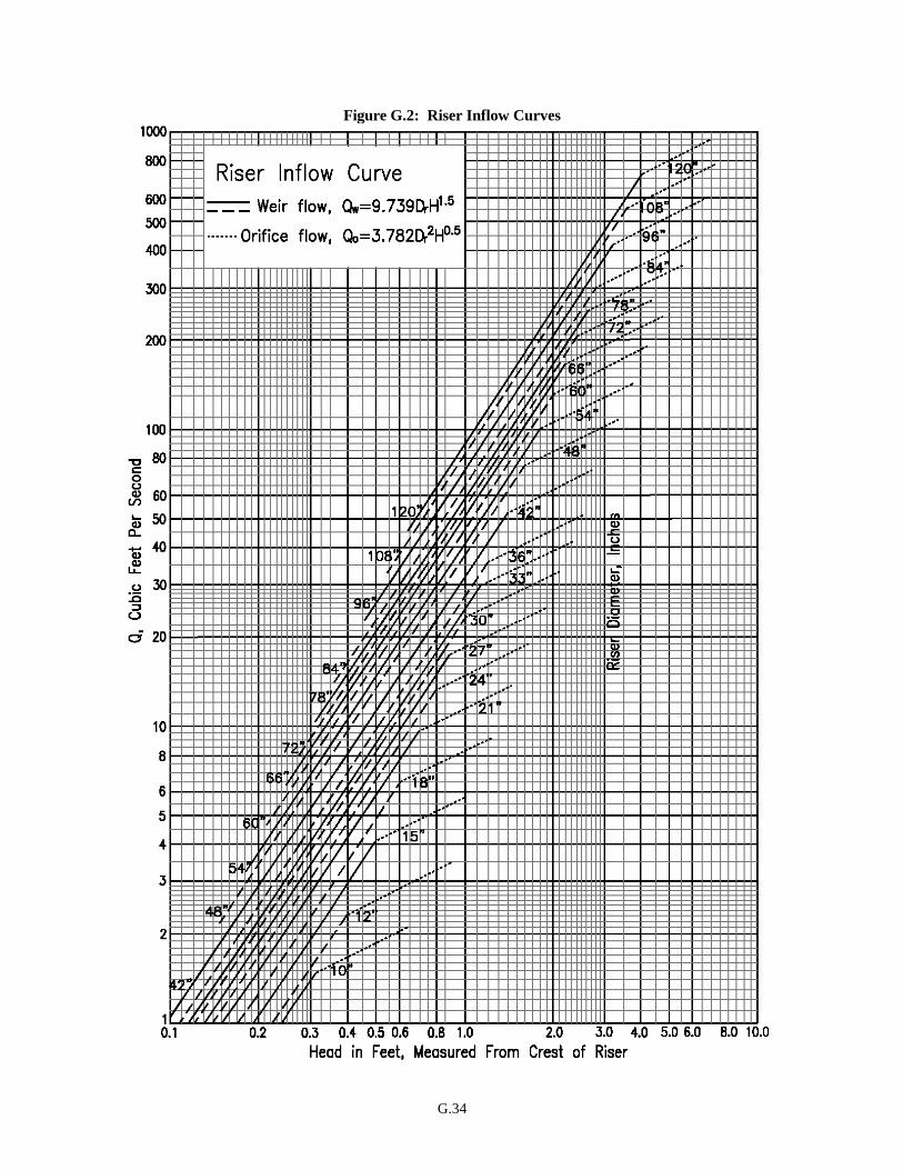
G.34
Figure G.2: Riser Inflow Curves
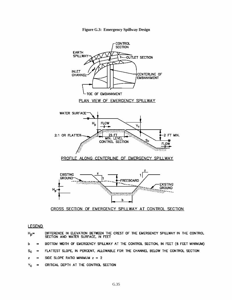
G.35
Figure G.3: Emergency Spillway Design
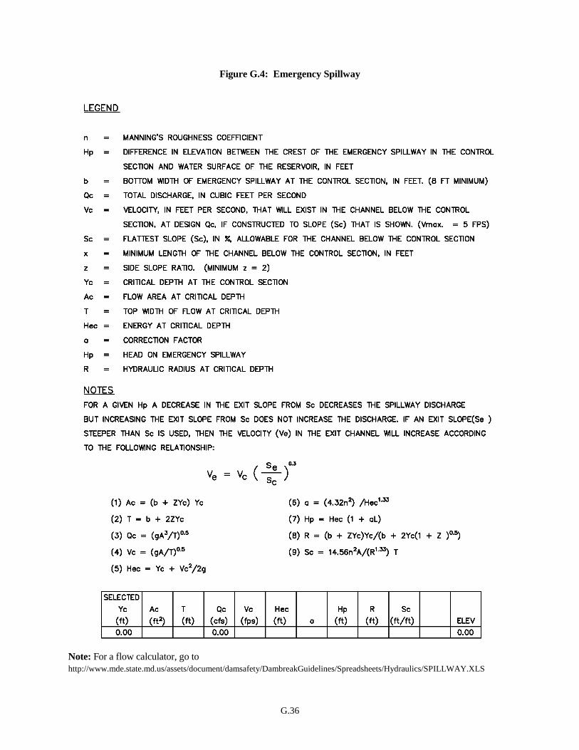
G.36
Figure G.4: Emergency Spillway
Note: For a flow calculator, go to
http://www.mde.state.md.us/assets/document/damsafety/DambreakGuidelines/Spreadsheets/Hydraulics/SPILLWAY.XLS
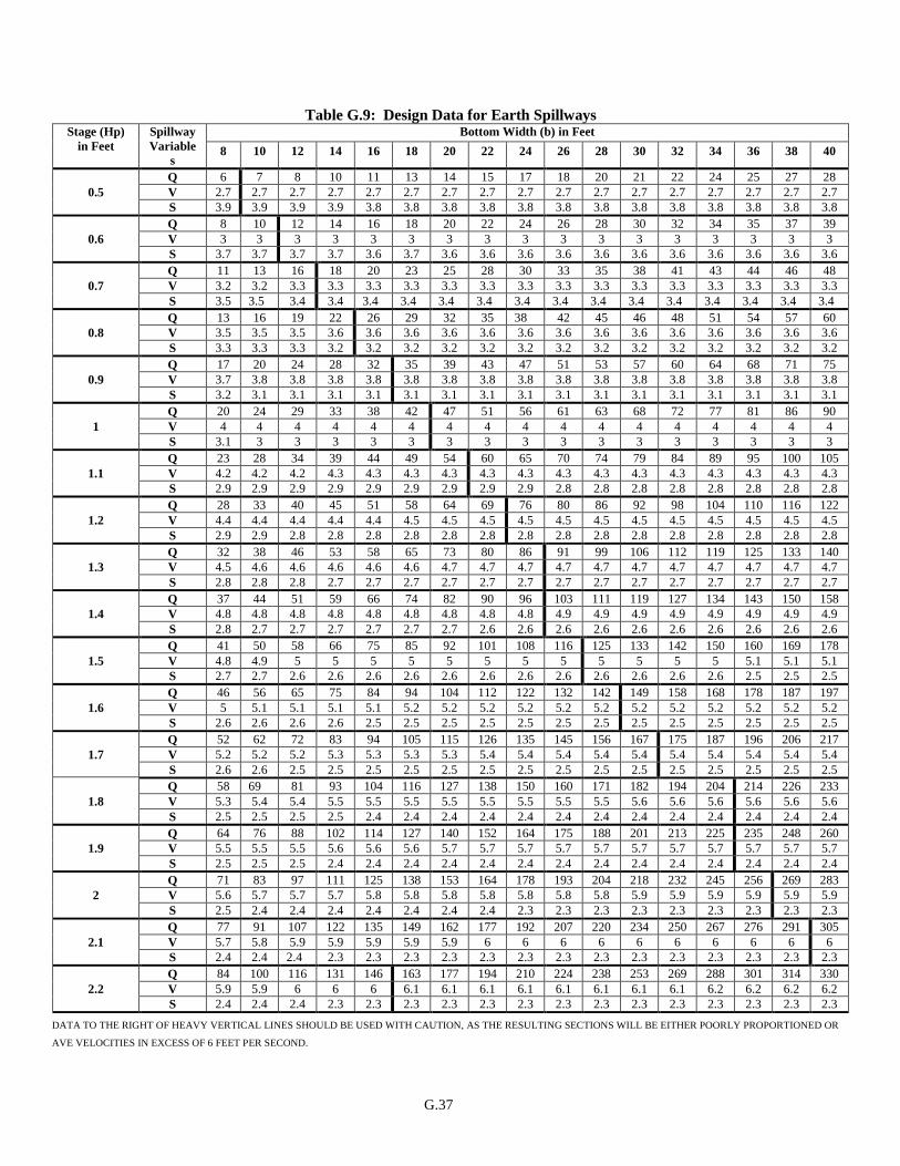
G.37
Table G.9: Design Data for Earth Spillways
DATA TO THE RIGHT OF HEAVY VERTICAL LINES SHOULD BE USED WITH CAUTION, AS THE RESULTING SECTIONS WILL BE EITHER POORLY PROPORTIONED OR
AVE VELOCITIES IN EXCESS OF 6 FEET PER SECOND.
Stage (Hp)
in Feet
Spillway
Variable
s
Bottom Width (b) in Feet
8 10 12 14 16 18 20 22 24 26 28 30 32 34 36 38 40
0.5
Q 6 7 8 10 11 13 14 15 17 18 20 21 22 24 25 27 28
V 2.7 2.7 2.7 2.7 2.7 2.7 2.7 2.7 2.7 2.7 2.7 2.7 2.7 2.7 2.7 2.7 2.7
S 3.9 3.9 3.9 3.9 3.8 3.8 3.8 3.8 3.8 3.8 3.8 3.8 3.8 3.8 3.8 3.8 3.8
0.6
Q 8 10 12 14 16 18 20 22 24 26 28 30 32 34 35 37 39
V 3 3 3 3 3 3 3 3 3 3 3 3 3 3 3 3 3
S 3.7 3.7 3.7 3.7 3.6 3.7 3.6 3.6 3.6 3.6 3.6 3.6 3.6 3.6 3.6 3.6 3.6
0.7
Q 11 13 16 18 20 23 25 28 30 33 35 38 41 43 44 46 48
V 3.2 3.2 3.3 3.3 3.3 3.3 3.3 3.3 3.3 3.3 3.3 3.3 3.3 3.3 3.3 3.3 3.3
S 3.5 3.5 3.4 3.4 3.4 3.4 3.4 3.4 3.4 3.4 3.4 3.4 3.4 3.4 3.4 3.4 3.4
0.8
Q 13 16 19 22 26 29 32 35 38 42 45 46 48 51 54 57 60
V 3.5 3.5 3.5 3.6 3.6 3.6 3.6 3.6 3.6 3.6 3.6 3.6 3.6 3.6 3.6 3.6 3.6
S 3.3 3.3 3.3 3.2 3.2 3.2 3.2 3.2 3.2 3.2 3.2 3.2 3.2 3.2 3.2 3.2 3.2
0.9
Q 17 20 24 28 32 35 39 43 47 51 53 57 60 64 68 71 75
V 3.7 3.8 3.8 3.8 3.8 3.8 3.8 3.8 3.8 3.8 3.8 3.8 3.8 3.8 3.8 3.8 3.8
S 3.2 3.1 3.1 3.1 3.1 3.1 3.1 3.1 3.1 3.1 3.1 3.1 3.1 3.1 3.1 3.1 3.1
1
Q 20 24 29 33 38 42 47 51 56 61 63 68 72 77 81 86 90
V 4 4 4 4 4 4 4 4 4 4 4 4 4 4 4 4 4
S 3.1 3 3 3 3 3 3 3 3 3 3 3 3 3 3 3 3
1.1
Q 23 28 34 39 44 49 54 60 65 70 74 79 84 89 95 100 105
V 4.2 4.2 4.2 4.3 4.3 4.3 4.3 4.3 4.3 4.3 4.3 4.3 4.3 4.3 4.3 4.3 4.3
S 2.9 2.9 2.9 2.9 2.9 2.9 2.9 2.9 2.9 2.8 2.8 2.8 2.8 2.8 2.8 2.8 2.8
1.2
Q 28 33 40 45 51 58 64 69 76 80 86 92 98 104 110 116 122
V 4.4 4.4 4.4 4.4 4.4 4.5 4.5 4.5 4.5 4.5 4.5 4.5 4.5 4.5 4.5 4.5 4.5
S 2.9 2.9 2.8 2.8 2.8 2.8 2.8 2.8 2.8 2.8 2.8 2.8 2.8 2.8 2.8 2.8 2.8
1.3
Q 32 38 46 53 58 65 73 80 86 91 99 106 112 119 125 133 140
V 4.5 4.6 4.6 4.6 4.6 4.6 4.7 4.7 4.7 4.7 4.7 4.7 4.7 4.7 4.7 4.7 4.7
S 2.8 2.8 2.8 2.7 2.7 2.7 2.7 2.7 2.7 2.7 2.7 2.7 2.7 2.7 2.7 2.7 2.7
1.4
Q 37 44 51 59 66 74 82 90 96 103 111 119 127 134 143 150 158
V 4.8 4.8 4.8 4.8 4.8 4.8 4.8 4.8 4.8 4.9 4.9 4.9 4.9 4.9 4.9 4.9 4.9
S 2.8 2.7 2.7 2.7 2.7 2.7 2.7 2.6 2.6 2.6 2.6 2.6 2.6 2.6 2.6 2.6 2.6
1.5
Q 41 50 58 66 75 85 92 101 108 116 125 133 142 150 160 169 178
V 4.8 4.9 5 5 5 5 5 5 5 5 5 5 5 5 5.1 5.1 5.1
S 2.7 2.7 2.6 2.6 2.6 2.6 2.6 2.6 2.6 2.6 2.6 2.6 2.6 2.6 2.5 2.5 2.5
1.6
Q 46 56 65 75 84 94 104 112 122 132 142 149 158 168 178 187 197
V 5 5.1 5.1 5.1 5.1 5.2 5.2 5.2 5.2 5.2 5.2 5.2 5.2 5.2 5.2 5.2 5.2
S 2.6 2.6 2.6 2.6 2.5 2.5 2.5 2.5 2.5 2.5 2.5 2.5 2.5 2.5 2.5 2.5 2.5
1.7
Q 52 62 72 83 94 105 115 126 135 145 156 167 175 187 196 206 217
V 5.2 5.2 5.2 5.3 5.3 5.3 5.3 5.4 5.4 5.4 5.4 5.4 5.4 5.4 5.4 5.4 5.4
S 2.6 2.6 2.5 2.5 2.5 2.5 2.5 2.5 2.5 2.5 2.5 2.5 2.5 2.5 2.5 2.5 2.5
1.8
Q 58 69 81 93 104 116 127 138 150 160 171 182 194 204 214 226 233
V 5.3 5.4 5.4 5.5 5.5 5.5 5.5 5.5 5.5 5.5 5.5 5.6 5.6 5.6 5.6 5.6 5.6
S 2.5 2.5 2.5 2.5 2.4 2.4 2.4 2.4 2.4 2.4 2.4 2.4 2.4 2.4 2.4 2.4 2.4
1.9
Q 64 76 88 102 114 127 140 152 164 175 188 201 213 225 235 248 260
V 5.5 5.5 5.5 5.6 5.6 5.6 5.7 5.7 5.7 5.7 5.7 5.7 5.7 5.7 5.7 5.7 5.7
S 2.5 2.5 2.5 2.4 2.4 2.4 2.4 2.4 2.4 2.4 2.4 2.4 2.4 2.4 2.4 2.4 2.4
2
Q 71 83 97 111 125 138 153 164 178 193 204 218 232 245 256 269 283
V 5.6 5.7 5.7 5.7 5.8 5.8 5.8 5.8 5.8 5.8 5.8 5.9 5.9 5.9 5.9 5.9 5.9
S 2.5 2.4 2.4 2.4 2.4 2.4 2.4 2.4 2.3 2.3 2.3 2.3 2.3 2.3 2.3 2.3 2.3
2.1
Q 77 91 107 122 135 149 162 177 192 207 220 234 250 267 276 291 305
V 5.7 5.8 5.9 5.9 5.9 5.9 5.9 6 6 6 6 6 6 6 6 6 6
S 2.4 2.4 2.4 2.3 2.3 2.3 2.3 2.3 2.3 2.3 2.3 2.3 2.3 2.3 2.3 2.3 2.3
2.2
Q 84 100 116 131 146 163 177 194 210 224 238 253 269 288 301 314 330
V 5.9 5.9 6 6 6 6.1 6.1 6.1 6.1 6.1 6.1 6.1 6.1 6.2 6.2 6.2 6.2
S 2.4 2.4 2.4 2.3 2.3 2.3 2.3 2.3 2.3 2.3 2.3 2.3 2.3 2.3 2.3 2.3 2.3
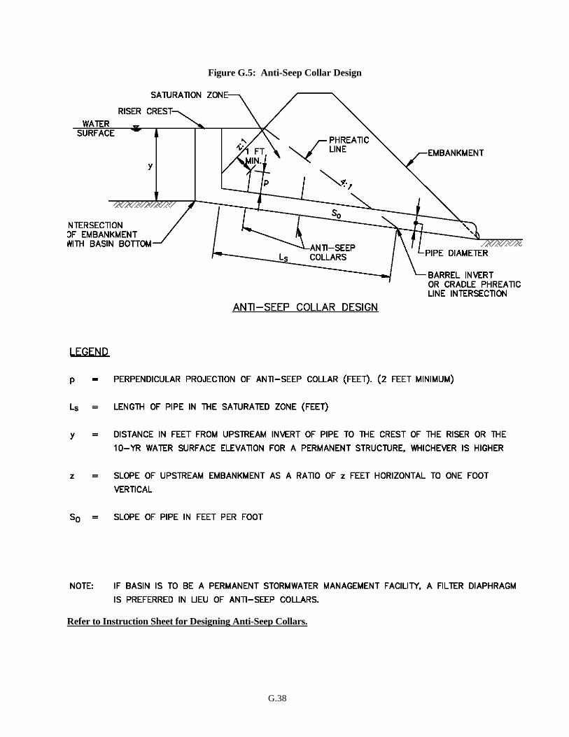
G.38
Figure G.5: Anti-Seep Collar Design
Refer to Instruction Sheet for Designing Anti-Seep Collars.

G.39
INSTRUCTION SHEET FOR
DESIGNING ANTI-SEEP COLLARS
(Refer to Figure G.5)
1. Determine the length of pipe within the embankment’s saturation zone (Ls) either graphically or if
the upstream slope of the embankment intersects the invert of the pipe at its upstream end, and the
slope of the pipe (So) is constant, the following equation may be used.
Ls = y(z+4)
(1-4So)
2. Determine the total perpendicular projection (P) required to increase Ls by 15 percent either
graphically as shown on Figure G.6 or by using the equation:
P = 0.075 Ls
3. Select the perpendicular projection (2 feet minimum) of the anti-seep collar(s) (p) when using
multiple collars.
4. Determine the number of anti-seep collars (N) required of the projection (P) using equation:
P/p = N
5. Either round up N, or repeat steps 3 and 4, to determine optimum p/N relationship.
6. Provide construction specifications relative to the materials to be used and method for attaching the
anti-seep collar(s) to the pipe in a watertight manner.
7. Space anti-seep collar(s) between 5 and 14 times the projection of each collar.
8. Place anti-seep collars a minimum of two feet from pipe joints.
9. Place anti-seep collars within the saturation zone. In cases where the spacing limit will not allow
this, place at least one collar in the saturation zone.
10. Use anti-seep collars constructed of the same material as the barrel pipe.
.
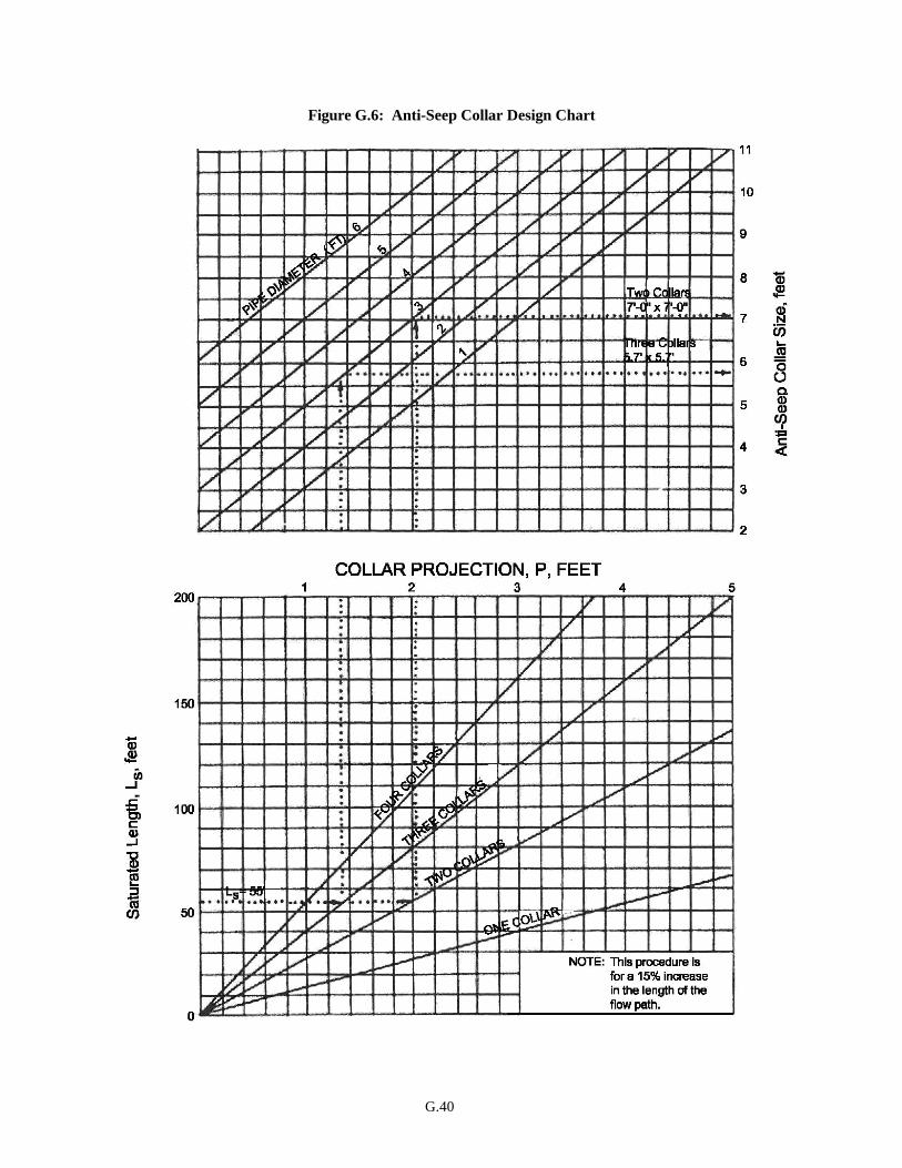
G.40
Figure G.6: Anti-Seep Collar Design Chart
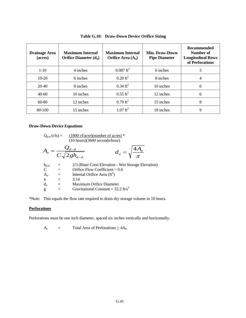
G.41
Table G.10: Draw-Down Device Orifice Sizing
Drainage Area
(acres)
Maximum Internal
Orifice Diameter (do)
Maximum Internal
Orifice Area (Ao)
Min. Draw-Down
Pipe Diameter
Recommended
Number of
Longitudinal Rows
of Perforations
1-10 4 inches 0.087 ft2 6 inches 3
10-20 6 inches 0.20 ft2 8 inches 4
20-40 8 inches 0.34 ft2 10 inches 6
40-60 10 inches 0.55 ft2 12 inches 6
60-80 12 inches 0.79 ft2 15 inches 8
80-100 15 inches 1.07 ft2 18 inches 9
Draw-Down Device Equations
Qd-d (cfs) = (1800 cf/acre)(number of acres) *
(10 hours)(3600 seconds/hour)
hd-d = 2/3 (Riser Crest Elevation - Wet Storage Elevation)
C = Orifice Flow Coefficient = 0.6
Ao = Internal Orifice Area (ft2)
π = 3.14
do = Maximum Orifice Diameter
g = Gravitational Constant = 32.2 ft/s2
*Note: This equals the flow rate required to drain dry storage volume in 10 hours.
Perforations
Perforations must be one inch diameter, spaced six inches vertically and horizontally.
At = Total Area of Perforations > 4A0
dd
ddo
ghC
QA
2
oo
Ad
4

G.42

G.43
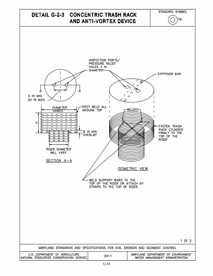
G.44

G.45

G.46
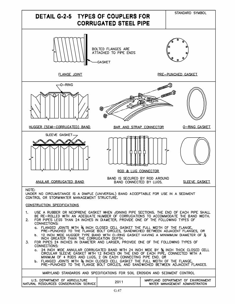
G.47
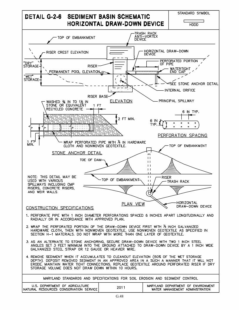
G.48
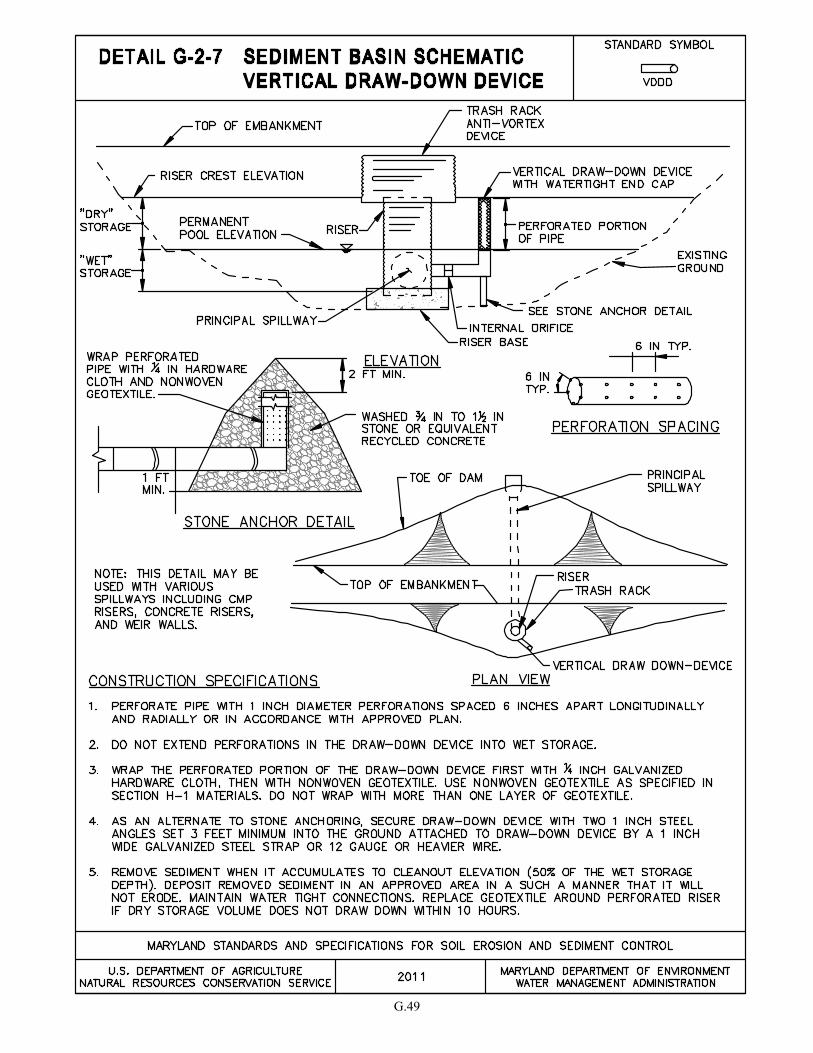
G.49

G.50
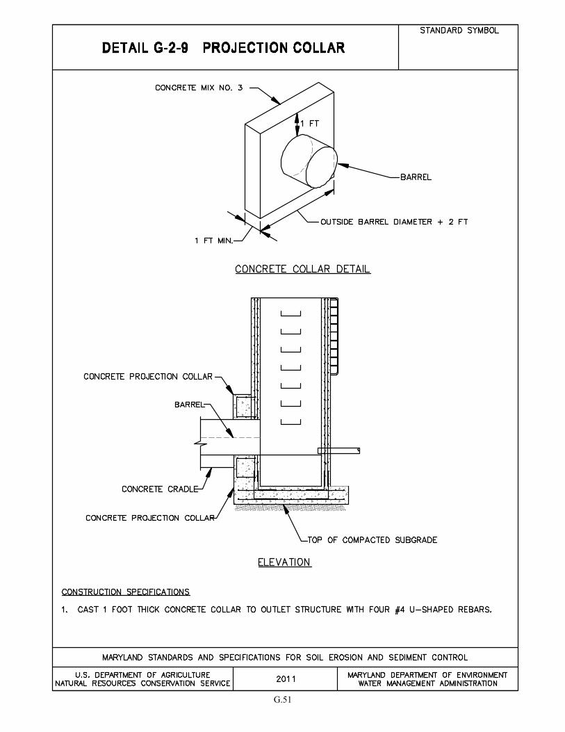
G.51


SECTION H – MISCELLANEOUS


H.1
H-1 STANDARDS AND SPECIFICATIONS
FOR
MATERIALS
Table H.1: Geotextile Fabrics
1 All numeric values except apparent opening size (AOS) represent minimum average roll values (MARV).
MARV is calculated as the typical minus two standard deviations. MD is machine direction; CD is cross
direction.
2
Values for AOS represent the average maximum opening.
Geotextiles must be evaluated by the National Transportation Product Evaluation Program (NTPEP) and
conform to the values in Table H.1.
The geotextile must be inert to commonly encountered chemicals and hydrocarbons and must be rot and mildew
resistant. The geotextile must be manufactured from fibers consisting of long chain synthetic polymers and
composed of a minimum of 95 percent by weight of polyolefins or polyesters, and formed into a stable network
so the filaments or yarns retain their dimensional stability relative to each other, including selvages.
When more than one section of geotextile is necessary, overlap the sections by at least one foot. The geotextile
must be pulled taut over the applied surface. Equipment must not run over exposed fabric. When placing
riprap on geotextile, do not exceed a one foot drop height.
WOVEN
SLIT FILM
GEOTEXTILE
WOVEN
MONOFILAMENT
GEOTEXTILE
NONWOVEN
GEOTEXTILE
MINIMUM AVERAGE ROLL VALUE1
PROPERTY TEST METHOD MD CD MD CD MD CD
Grab Tensile Strength ASTM D-4632 200 lb 200 lb 370 lb 250 lb 200 lb 200 lb
Grab Tensile Elongation ASTM D-4632 15% 10% 15% 15% 50% 50%
Trapezoidal Tear Strength ASTM D-4533 75 lb 75 lb 100 lb 60 lb 80 lb 80 lb
Puncture Strength ASTM D-6241 450 lb 900 lb 450 lb
Apparent Opening Size2 ASTM D-4751
U.S. Sieve 30
(0.59 mm)
U.S. Sieve 70
(0.21 mm) U.S. Sieve 70
(0.21 mm)
Permittivity ASTM D-4491 0.05 sec-1
0.28 sec-1
1.1 sec-1
Ultraviolet Resistance
Retained at 500 hours ASTM D-4355 70% strength 70% strength 70% strength

H.2
Table H.2: Stone Size
TYPE SIZE RANGE d50 d100 AASHTO MIDSIZE
WEIGHT3
NUMBER 571 3/8 to 1 ½ inch ½ in 1 ½ in M-43 N/A
NUMBER 1 2 to 3 inch 2 ½ in 3 in M-43 N/A
RIPRAP2
(CLASS 0) 4 to 7 inch 5 ½ in 7 in N/A N/A
CLASS I N/A 9 ½ in 15 in N/A 40 lb
CLASS II N/A 16 in 24 in N/A 200 lb
CLASS III N/A 23 in 34 in N/A 600 lb
1 This classification is to be used on the upstream face of stone outlets and check dams.
2 This classification is to be used for gabions.
3 Optimum gradation is 50 percent of the stone being above and 50 percent below the midsize.
Stone must be composed of a well graded mixture of stone sized so that fifty (50) percent of the pieces by weight
are larger than the size determined by using the charts. A well graded mixture, as used herein, is defined as a
mixture composed primarily of larger stone sizes but with a sufficient mixture of other sizes to fill the smaller
voids between the stones. The diameter of the largest stone in such a mixture must not exceed the respective d100
selected from Table H.2. The d50 refers to the median diameter of the stone. This is the size for which 50
percent, by weight, will be smaller and 50 percent will be larger.
Note: Recycled concrete equivalent may be substituted for all stone classifications for temporary control
measures only. Concrete broken into the sizes meeting the appropriate classification, containing no steel
reinforcement, and having a minimum density of 150 pounds per cubic foot may be used as an equivalent.
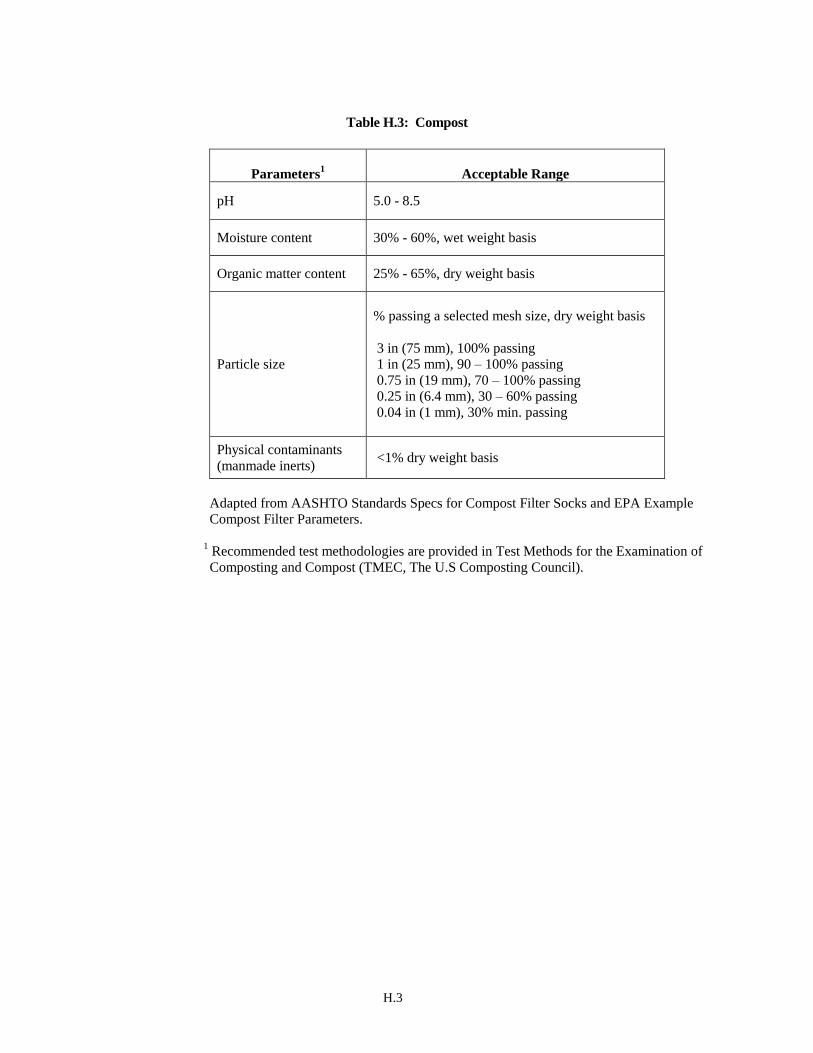
H.3
Table H.3: Compost
Parameters1
Acceptable Range
pH 5.0 - 8.5
Moisture content 30% - 60%, wet weight basis
Organic matter content 25% - 65%, dry weight basis
Particle size
% passing a selected mesh size, dry weight basis
3 in (75 mm), 100% passing
1 in (25 mm), 90 – 100% passing
0.75 in (19 mm), 70 – 100% passing
0.25 in (6.4 mm), 30 – 60% passing
0.04 in (1 mm), 30% min. passing
Physical contaminants
(manmade inerts) <1% dry weight basis
Adapted from AASHTO Standards Specs for Compost Filter Socks and EPA Example
Compost Filter Parameters.
1 Recommended test methodologies are provided in Test Methods for the Examination of
Composting and Compost (TMEC, The U.S Composting Council).
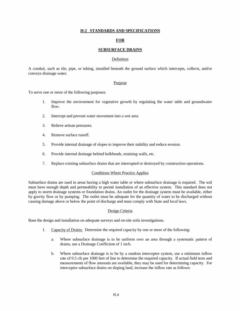
H.4
H-2 STANDARDS AND SPECIFICATIONS
FOR
SUBSURFACE DRAINS
Definition
A conduit, such as tile, pipe, or tubing, installed beneath the ground surface which intercepts, collects, and/or
conveys drainage water.
Purpose
To serve one or more of the following purposes:
1. Improve the environment for vegetative growth by regulating the water table and groundwater
flow.
2. Intercept and prevent water movement into a wet area.
3. Relieve artisan pressures.
4. Remove surface runoff.
5. Provide internal drainage of slopes to improve their stability and reduce erosion.
6. Provide internal drainage behind bulkheads, retaining walls, etc.
7. Replace existing subsurface drains that are interrupted or destroyed by construction operations.
Conditions Where Practice Applies
Subsurface drains are used in areas having a high water table or where subsurface drainage is required. The soil
must have enough depth and permeability to permit installation of an effective system. This standard does not
apply to storm drainage systems or foundation drains. An outlet for the drainage system must be available, either
by gravity flow or by pumping. The outlet must be adequate for the quantity of water to be discharged without
causing damage above or below the point of discharge and must comply with State and local laws.
Design Criteria
Base the design and installation on adequate surveys and on-site soils investigations.
1. Capacity of Drains: Determine the required capacity by one or more of the following:
a. Where subsurface drainage is to be uniform over an area through a systematic pattern of
drains, use a Drainage Coefficient of 1 inch.
b. Where subsurface drainage is to be by a random interceptor system, use a minimum inflow
rate of 0.5 cfs per 1000 feet of line to determine the required capacity. If actual field tests and
measurements of flow amounts are available, they may be used for determining capacity. For
interceptor subsurface drains on sloping land, increase the inflow rate as follows:
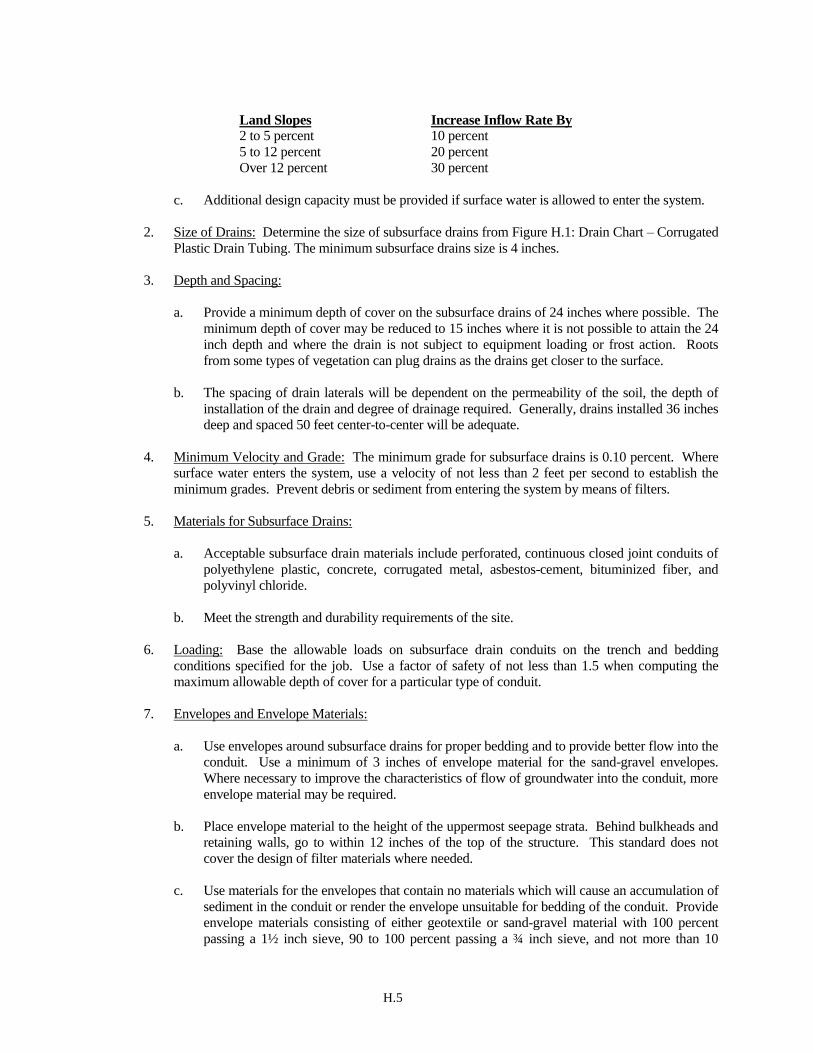
H.5
Land Slopes Increase Inflow Rate By 2 to 5 percent 10 percent
5 to 12 percent 20 percent
Over 12 percent 30 percent
c. Additional design capacity must be provided if surface water is allowed to enter the system.
2. Size of Drains: Determine the size of subsurface drains from Figure H.1: Drain Chart – Corrugated
Plastic Drain Tubing. The minimum subsurface drains size is 4 inches.
3. Depth and Spacing:
a. Provide a minimum depth of cover on the subsurface drains of 24 inches where possible. The
minimum depth of cover may be reduced to 15 inches where it is not possible to attain the 24
inch depth and where the drain is not subject to equipment loading or frost action. Roots
from some types of vegetation can plug drains as the drains get closer to the surface.
b. The spacing of drain laterals will be dependent on the permeability of the soil, the depth of
installation of the drain and degree of drainage required. Generally, drains installed 36 inches
deep and spaced 50 feet center-to-center will be adequate.
4. Minimum Velocity and Grade: The minimum grade for subsurface drains is 0.10 percent. Where
surface water enters the system, use a velocity of not less than 2 feet per second to establish the
minimum grades. Prevent debris or sediment from entering the system by means of filters.
5. Materials for Subsurface Drains:
a. Acceptable subsurface drain materials include perforated, continuous closed joint conduits of
polyethylene plastic, concrete, corrugated metal, asbestos-cement, bituminized fiber, and
polyvinyl chloride.
b. Meet the strength and durability requirements of the site.
6. Loading: Base the allowable loads on subsurface drain conduits on the trench and bedding
conditions specified for the job. Use a factor of safety of not less than 1.5 when computing the
maximum allowable depth of cover for a particular type of conduit.
7. Envelopes and Envelope Materials:
a. Use envelopes around subsurface drains for proper bedding and to provide better flow into the
conduit. Use a minimum of 3 inches of envelope material for the sand-gravel envelopes.
Where necessary to improve the characteristics of flow of groundwater into the conduit, more
envelope material may be required.
b. Place envelope material to the height of the uppermost seepage strata. Behind bulkheads and
retaining walls, go to within 12 inches of the top of the structure. This standard does not
cover the design of filter materials where needed.
c. Use materials for the envelopes that contain no materials which will cause an accumulation of
sediment in the conduit or render the envelope unsuitable for bedding of the conduit. Provide envelope materials consisting of either geotextile or sand-gravel material with 100 percent
passing a 1½ inch sieve, 90 to 100 percent passing a ¾ inch sieve, and not more than 10

H.6
percent passing a No. 60 sieve.
d. Use woven monofilament geotextile envelopes where 10 percent or more of the backfill
material passes a No. 200 sieve. Place the envelope in such a manner that once the conduit is
installed, it will be completely encased. For other soils use nonwoven geotextile.
e. Place and bed the conduit in a sand-gravel envelope. Place a minimum of 3 inches of
envelope materials on the bottom of a conventional trench. Place the conduit on this and fill
the trench completely with envelope material to a minimum depth of 3 inches above the
conduit.
f. Stabilize soft or yielding soils under the drain where required and protect lines from
settlement by adding gravel or other suitable material to the trench, by placing the conduit on
plank or other rigid support, or by using long sections of perforated or watertight pipe with
adequate strength to ensure satisfactory subsurface drain performance.
g. Where local regulations do not allow sand-gravel envelopes, follow the local design for type
and size of envelope material.
8. Use of Heavy Duty Corrugated Plastic Drainage Tubing: Specify heavy duty corrugated drainage
tubing where rocky or gravelly soils are expected to be encountered during installation operations.
The quality of tubing will also be specified when cover over this tubing is expected to exceed 24
inches for 4, 5, 6, or 8 inch tubing. Larger size tubing designs will be handled on an individual job
basis.
9. Auxiliary Structure and Subsurface Drain Protection:
a. Protect the outlet against erosion and undermining of the conduit, against damaging periods
of submergence, and against entry of rodents or other animals into the subsurface drain.
Install an animal guard on the outlet end of the pipe. Use a continuous 10 foot section of
corrugated metal, cast iron, or steel pipe without perforations at the outlet end of the line and
outlet 1.0 foot above the normal elevation of low flow in the outlet channel or above mean
high tide in tidal areas. Do not provide envelope material around this 10 foot section of pipe.
b. Design conduits under roadways and embankments to be watertight and to withstand the
expected loads.
c. Where surface water is to be admitted to subsurface drains, design the inlets to exclude debris
and prevent sediment from entering the conduit. Design lines flowing under pressure to
withstand the resulting pressures and velocity of flow. Use surface waterways where feasible.
d. Cap the upper end of each subsurface drain line with a tight fitting cap of the same material as
the conduit or other durable material unless connected to a structure.
Maintenance
The point of discharge must be kept free of erosion and the animal guard at the outlet maintained.

H.7
Figure H.1: Drain Chart – Corrugated Plastic Drain Tubing
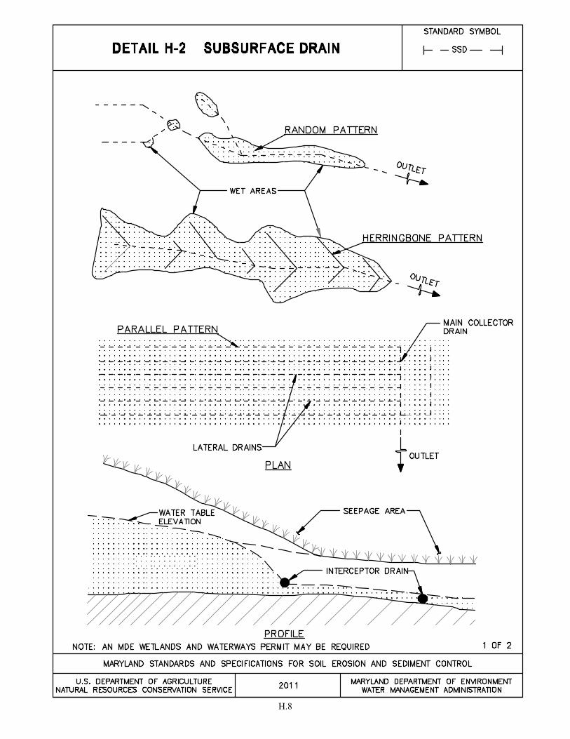
H.8
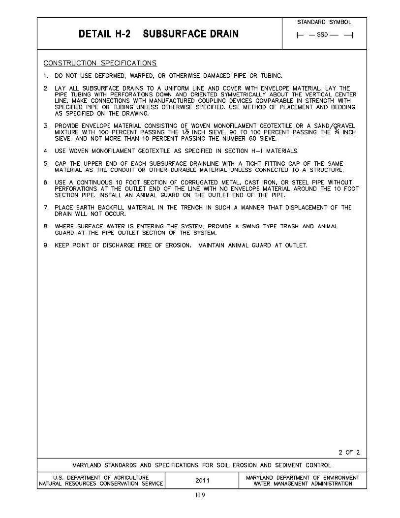
H.9
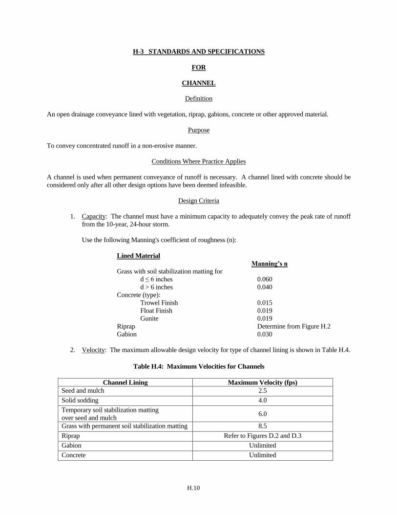
H.10
H-3 STANDARDS AND SPECIFICATIONS
FOR
CHANNEL
Definition
An open drainage conveyance lined with vegetation, riprap, gabions, concrete or other approved material.
Purpose
To convey concentrated runoff in a non-erosive manner.
Conditions Where Practice Applies
A channel is used when permanent conveyance of runoff is necessary. A channel lined with concrete should be
considered only after all other design options have been deemed infeasible.
Design Criteria
1. Capacity: The channel must have a minimum capacity to adequately convey the peak rate of runoff
from the 10-year, 24-hour storm.
Use the following Manning's coefficient of roughness (n):
Lined Material
Manning’s n
Grass with soil stabilization matting for
d ≤ 6 inches 0.060
d > 6 inches 0.040
Concrete (type):
Trowel Finish 0.015
Float Finish 0.019
Gunite 0.019
Riprap Determine from Figure H.2
Gabion 0.030
2. Velocity: The maximum allowable design velocity for type of channel lining is shown in Table H.4.
Table H.4: Maximum Velocities for Channels
Channel Lining Maximum Velocity (fps)
Seed and mulch 2.5
Solid sodding 4.0
Temporary soil stabilization matting
over seed and mulch 6.0
Grass with permanent soil stabilization matting 8.5
Riprap Refer to Figures D.2 and D.3
Gabion Unlimited
Concrete Unlimited

H.11
3. Cross-Section: Cross-sections should be triangular, parabolic, or trapezoidal in shape. Monolithic
concrete or gabions may be rectangular.
4. Freeboard: The lined section must extend up the side slopes to a minimum of 0.25 feet above the
design depth. The side slopes above the permanent lining must be vegetated or otherwise stabilized
and extend a minimum of 0.25 feet above the top of the lining.
5. Side Slopes and Lining Thickness: Steepest permissible side slopes, horizontal to vertical (H:V),
and minimum lining thicknesses are as follows:
Table H.5: Steepest Permissible Side Slopes and Minimum Lining Thickness
Channel Type Side Slopes Minimum Lining Thickness
Non-reinforced concrete
Hand-placed, formed concrete
Heights of lining, 1½ feet or less
Vertical 4 inches
Non-reinforced concrete
Hand-placed, screened concrete or
mortared in place flagstone
Height of lining, less than 2 feet
Height of lining, more than 2 feet
1:1
2:1
4 inches
Slip Form Concrete
Height of lining, less than 2 feet 1:1 4 inches
Riprap 2:1 1½ times max. stone size plus
thickness of filter or bedding
Gabion Per manufacturer
specifications Per manufacturer specifications
Permanent soil stabilization matting 2:1 Per manufacturer specifications
6. Related Structures: Design side inlets, drop structures, and energy dissipaters to meet the hydraulic
and structural requirements of the site.
7. Filters or Bedding: Provide for filters or bedding to prevent piping, reduce uplift pressure, and
collect water as required and in accordance with sound engineering design. Provide weep holes and
drains as needed.
8. Concrete:
a. Specify the proportion of concrete to be used for lining so that it is plastic enough for thorough
consolidation and stiff enough to stay in place on side slopes. A dense durable product will be
required. A mix that can be certified as suitable to produce a minimum strength of at least
3,000 pounds per square inch is required. Use Portland cement, Type I, II, IV, or V with an
aggregate having a maximum diameter of 1½ inches.
b. Provide weep holes in concrete footings and retaining walls to allow free drainage of water. Use
non-corrosive pipe for the weep holes.

H.12
9. Mortar: Use mortar consisting of a mix of cement, sand, and water with a water-cement ratio of not
more than 6 gallons of water per bag of cement for placement of flagstone.
10. Construction Joints: Allow for form construction joints in concrete linings, where required,
transversely to a depth of about ⅓ the thickness of the lining at a uniform spacing in the range of 10
to 15 feet.
11. Rock Riprap: Provide stone used for riprap or gabions of a density and hardness to withstand
exposure to air, water, freezing, and thawing.
12. Cutoff Walls: Use cutoff walls at the beginning and ending of concrete lining and for rock riprap
lining, and key into the channel bottom at both ends of the lining.
13. Gabion Baskets: Fabricate gabions in such a manner that the sides, ends, and lid can be assembled
at the site into rectangular baskets of similar size. Install gabion baskets according to the
manufacturer specifications.
14. Geotextile: Provide for nonwoven geotextile beneath all riprap and gabions.
Construction Specifications
1. Clear the foundation area of trees, stumps, roots, sod, loose rock, or other objectionable material.
2. Excavate the cross-section to the lines and grades as shown on the plans. Backfill over-excavated
areas with moist soil compacted to the density of the surrounding material.
3. Construct the grade or horizontal alignment of the lined channel as per the plans.
4. Place concrete linings to the thickness shown on the plans and finish in a professional manner.
Protect freshly placed concrete from freezing or extremely high temperatures to ensure proper
curing.
5. Place filter, bedding, and riprap to line and grade in the manner specified.
6. Construct channels in such a manner that erosion, air, and water pollution will be minimized and
held within legal limits. The completed job will have a professional appearance. Vegetate all
disturbed areas or otherwise protect against soil erosion.
Maintenance
The line, grade, and cross section must be maintained. Maintain the lining as designed to prevent undermining
and deterioration. Positive drainage must be maintained. Accumulated sediment and debris must be removed.
The channel and the point of discharge must be kept free of erosion.

H.13
Figure H.2: Determining “n” for Riprap Lined Channel using Depth of Flow
]0.14)(log6.21[5010
81
dy
yn
(y =Depth of Flow)
H.14
H-4 STANDARDS AND SPECIFICATIONS
FOR
TEMPORARY ACCESS WATERWAY CROSSINGS
Definition
A structure placed across a waterway to provide access for construction purposes for a period of less than one
year. Temporary access crossings are not to be utilized to maintain traffic for the general public.
Purpose
To provide safe, pollution free access across a waterway for construction equipment by establishing minimum
standards and specifications for the design, construction, maintenance, and removal of the structure. A temporary
access waterway crossing is necessary to prevent construction equipment from damaging the waterway, blocking
fish migration, and tracking sediment and other pollutants into the waterway. A waterway crossing may create a
channel constriction, thus the temporary nature of waterway access crossings must be stressed. The crossing
should be in place for the shortest practical period of time and removed as soon as its function is completed.
Conditions Where Practice Applies
Temporary waterway crossings must conform to the technical requirements of these Standards and Specifications
as well as any specific requirements imposed by the MDE Wetlands and Waterways Program. The designs are
based on waterway geometry rather than the drainage area contributing to the point of crossing. The principal
consideration of these Standards and Specifications is erosion and sediment control. Structural integrity and
safety for expected loading must also be considered when designing temporary access waterway crossings. The
two types of standard temporary waterway crossings are bridges and culverts. Bridges are preferable.
Design Criteria
1. Stream Closures: The stream channel must not be disturbed during restricted time periods.
Stream closure dates for fish spawning or migration within waterways are as follows:
Use I and IP March 1 - June 15
Use II June 1 - September 30 and December 16 - March 14
Use III and IIIP October 1 - April 30
Use IV March 1 - May 31
SAV* April 1 - October 15
* Submerged Aquatic Vegetation (SAV)
For more information about the closures based on stream uses and SAVs contact MDE
Wetlands and Waterways Program.
2. Aquatic Migration: Fish passage must not be obstructed by the installation of a waterway
crossing. Bridges pose the least potential for creating barriers to aquatic migration. The
construction of a waterway crossing must not cause a significant water level difference between
the upstream and downstream water surface elevations.

H.15
3. Site Location: Locate the temporary crossing where there will be the least disturbance to the
existing waterway banks and approaches. When possible, locate the crossing at a point
receiving minimal surface runoff. Consider the effort that will be required to restore the area
after the temporary crossing is removed.
4. Crossing Alignment: The temporary waterway crossing should be at right angles to the stream,
unless the approach conditions dictate otherwise.
5. Approaches: The centerline of both approaches needs to coincide with the centerline of the
crossing for a minimum distance of 50 feet from the top of each stream bank, unless precluded
by physical or right-of-way constraints. The approaches should be kept as close to the existing
grade as possible. Approaches should have a minimum width of 12 feet and a maximum width
of 20 feet depending on the size of the vehicles that will use the crossing.
6. Surface Runoff: Runoff on the approaches must be at a non-erosive velocity. This can be
attained through surface stabilization or surface runoff diversion. Surface runoff from
unstabilized approaches must discharge to an approved sediment control device.
7. Removal: After the temporary crossing is no longer needed, remove it within 14 calendar days
unless within the use designation stream closure period.
H.16
H-4-1 STANDARDS AND SPECIFICATIONS
FOR
TEMPORARY ACCESS BRIDGE
Definition
A temporary waterway crossing that spans the stream channel.
Design Considerations
Generally, a temporary access bridge causes less disturbance to the waterway bed and banks and poses less
interference with fish migration than a culvert access crossing.
Time-of-year restrictions do not apply to the construction or removal of a temporary access bridge unless there is
disturbance to the stream channel.
Maintenance
The approach to the bridge must be stabilized and kept free of erosion. The decking and curbs must be cleaned of
sediment daily by scraping, sweeping, and/or vacuuming. The decking and curbs must remain tightly butted
without gaps. Debris trapped by the bridge must be removed. The areas adjacent to the crossing must be
maintained to continuously meet the requirements for Adequate Vegetative Establishment in accordance with
Section B-4 Vegetative Stabilization.
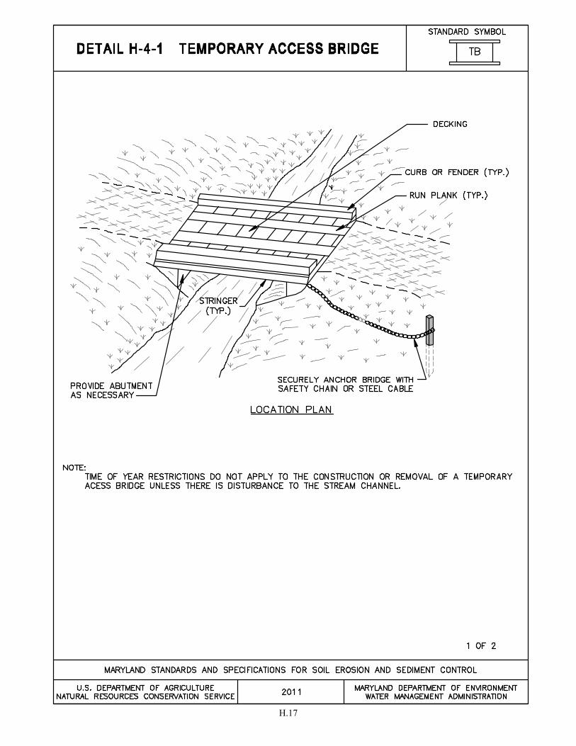
H.17

H.18
H.19
H-4-2 STANDARDS AND SPECIFICATIONS
FOR
TEMPORARY ACCESS CULVERT
Definition
A waterway crossing consisting of circular pipe(s) and aggregate.
Design Criteria
1. Temporary culverts are used where the channel is too wide for a single span bridge or the
anticipated loading may prove unsafe. The culvert type and cross sectional area must be strong
enough to support the maximum expected load.
2. Size the pipe(s) to convey the normal stream flow. The cross-sectional area of the culvert must be
greater than 60 percent of the cross-sectional area of the existing bankfull channel. Size the culvert
for the largest pipe diameters that will fit into the existing waterway channel without excavation of
the channel or without major approach fills. The minimum pipe diameter that may be used is 12
inches.
3. Time-of-year restrictions apply to the construction or removal of a temporary access culvert.
Maintenance
The approach to the access culvert must be stabilized and kept free of erosion. Displaced stone must be replaced,
and high flow areas must be maintained. Debris trapped by the culvert must be removed. Damaged pipe(s) must
be replaced. The areas adjacent to the crossing must be maintained to continuously meet the requirements for
Adequate Vegetative Establishment in accordance with Section B-4 Vegetative Stabilization.
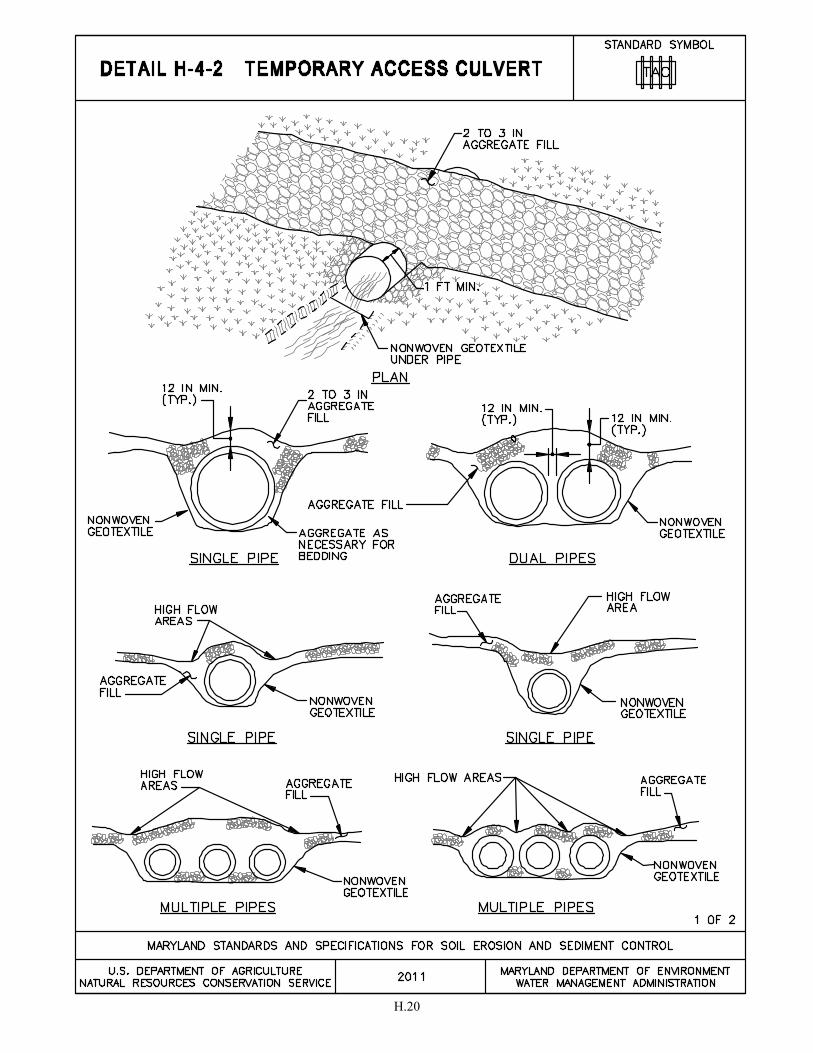
H.20
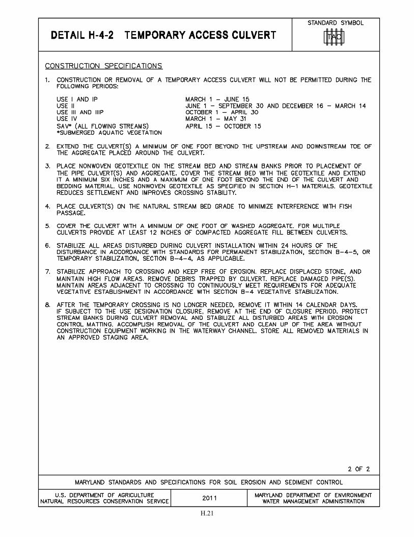
H.21
H.22
H-5 STANDARDS AND SPECIFICATIONS
FOR
DUST CONTROL
Definition
Controlling the suspension of dust particles from construction activities.
Purpose
To prevent blowing and movement of dust from exposed soil surfaces to reduce on and off-site damage including
health and traffic hazards.
Conditions Where Practice Applies
Areas subject to dust blowing and movement where on and off-site damage is likely without treatment.
Specifications
1. Mulches: See Section B-4-2 Soil Preparation, Topsoiling, and Soil Amendments, Section B-4-3
Seeding and Mulching, and Section B-4-4 Temporary Stabilization. Mulch must be anchored to
prevent blowing.
2. Vegetative Cover: See Section B-4-4 Temporary Stabilization.
3. Tillage: Till to roughen surface and bring clods to the surface. Begin plowing on windward
side of site. Chisel-type plows spaced about 12 inches apart, spring-toothed harrows, and
similar plows are examples of equipment that may produce the desired effect.
4. Irrigation: Sprinkle site with water until the surface is moist. Repeat as needed. The site must
not be irrigated to the point that runoff occurs.
5. Barriers: Solid board fences, silt fences, snow fences, burlap fences, straw bales, and similar
material can be used to control air currents and soil blowing.
6. Chemical Treatment: Use of chemical treatment requires approval by the appropriate plan
review authority.
H.23
H-6 STANDARDS AND SPECIFICATIONS
FOR
ONSITE CONCRETE WASHOUT STRUCTURE
Definition
A prefabricated or fabricated container used for containing wash water from rinsing out concrete trucks, drums,
pumps, chutes, other equipment, and concrete truck exteriors.
Purpose
To promote proper disposal of waste concrete and wash water by containing it onsite thereby preventing
contamination of waterways, groundwater, and storm drains.
Conditions Where Practice Applies
Concrete washout structures are used when concrete equipment is cleaned onsite.
Design Criteria
1. Concrete washout structures must be located a minimum of 50 feet away from open channels,
storm drain inlets, sensitive areas, wetlands, buffers, and waterways.
2. The location of the washout structure must be away from construction traffic.
3. Excavated washout structures must be located so that they do not intercept surface runoff. If
runoff drains toward an excavated structure, a diversion must be provided around the structure.
4. Prefabricated containers are an acceptable alternative to fabricated washout structures provided
the volume is adequate to contain all wash water and solids while maintaining at least 4 inches
of freeboard.
Maintenance
It is critical that the concrete washout structure be watertight. The impermeable liner needs to be replaced if
damaged (e.g., ripped or punctured). A washout structure that is 75 percent full must be emptied or replaced, and
the accumulated material must be disposed of properly. The liner may not be reused. Prefabricated containers
require less maintenance. Stored liquids that have not evaporated can be wet vacuumed and disposed of in an
approved manner. Prior to forecasted rainstorms, remove liquids or cover the structure to prevent overflows.
Hardened solids can be removed whole or broken up for disposal or recycling. Runoff diversion(s) around an
excavated washout structure must be maintained until the structure is removed.
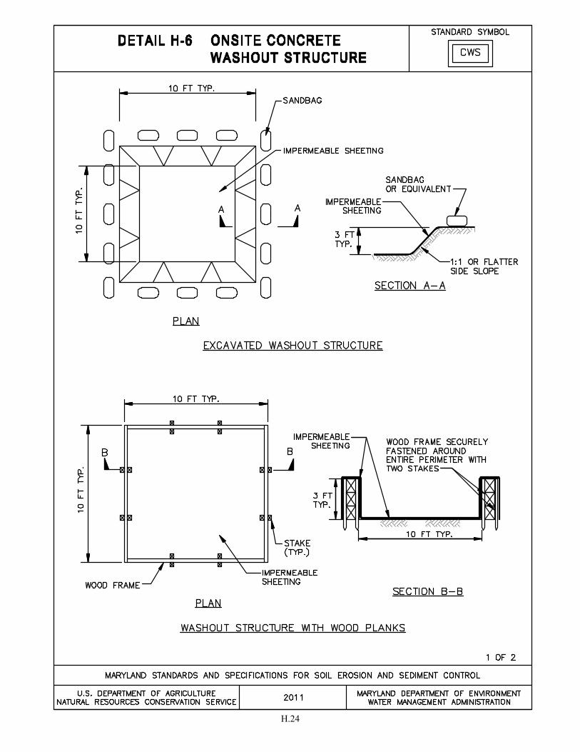
H.24
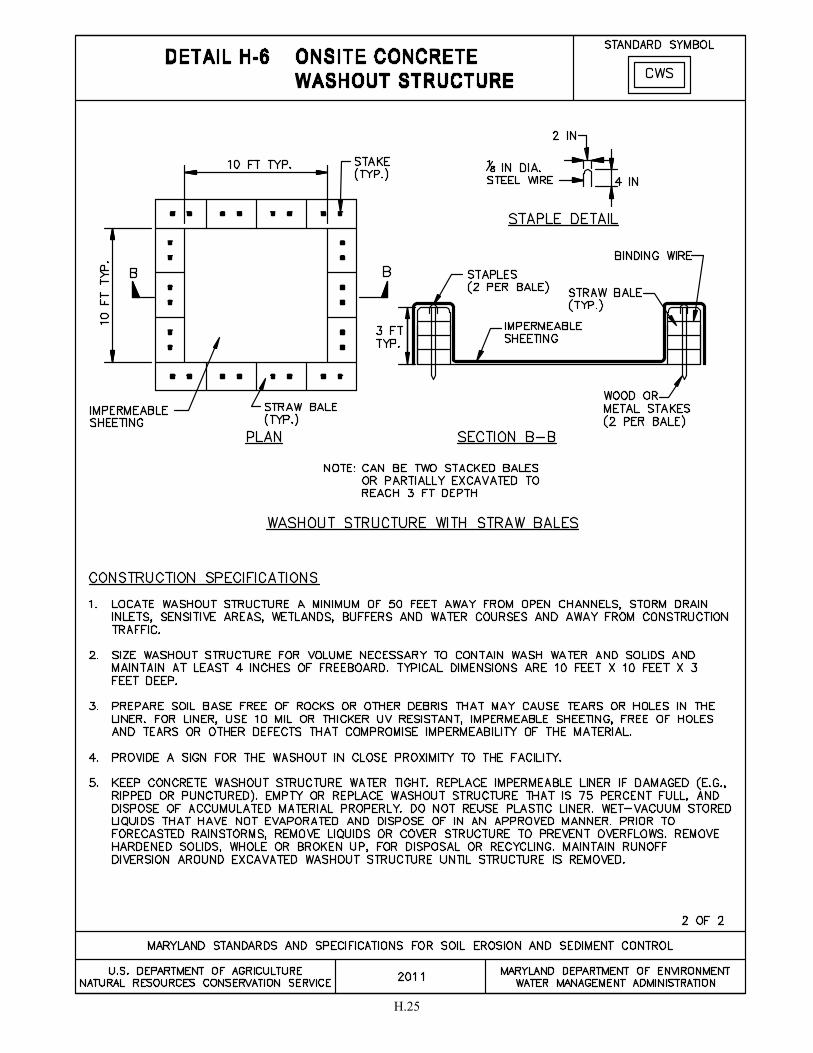
H.25


BIBLIOGRAPHY

BB.1
BIBLIOGRAPHY Alabama Handbook for Erosion Control, Sediment Control, and Stormwater Management on Construction Sites and Urban Areas. 2009. http://swcc.alabama.gov/pdf/Handbooks&Guides/Complete%20ESC%20Handbook10-09.pdf as of August, 2009. Alexander, R. 2006. “Standard Specification for Compost for Erosion/Sediment Control (Filter Berms and Filter Socks).” Apex, NC. Barfield, Billy J. and Clar, Michael L. 1985. “Development of New Design Criteria for Sediment Traps and Basins.” Barrett, M.E., Kearney, J.E., McCoy, T.G., Malina, J.F. 1995. “An Evaluation of the Use and Effectiveness of Temporary Sediment Controls.” Center for Research in Water Resources. Austin, TX. University of Texas at Austin. Fifield, J.S., 2004. Designing for Effective Sediment and Erosion Control on Construction Sites. Forester Press, Santa Barbara, CA. 305 pp. Florida Erosion and Sediment Control Designer and Reviewer Manual. 2007. Florida Department of Transportation, Florida Department of Environmental Protection. Tallahassee, FL. Georgia Soil and Water Conservation Commission, Manual for Erosion and Sediment Control in Georgia, 5th Edition. 2000. Athens, GA. Hahn, C.T., Barfield, B.J., Hayes, J.C., Design Hydrology and Sedimentology for Small Catchments. 1994. Academic Press, Inc. San Diego, CA. Hoan, CT., Tapp, J.S. 1980. "Design of Sedimentation Basins." NCHRP Synthesis of Highway Practices Maryland Department of the Environment, 2000 Maryland Stormwater Design Manual, Volumes I and II. Chapter 5, Supplement, Environmental Site Design. 2007. Baltimore, MD. Maryland Department of Transportation, State Highway Administration, Standards and Specifications for Construction and Materials. 2008. Baltimore, MD. Maryland Department of Transportation, State Highway Administration, Landscape Design Guidelines Soil Stabilization Matting. 2010. Baltimore, MD. McLaughlin, R.A. and A. Zimmerman, 2009. “Best Management Practices for Chemical Treatment Systems for Construction Stormwater and Dewatering.” Final Report, FHWA, January 2009. New Jersey Department of Transportation, Soil Erosion and Sediment Control Standards. 2008. New York State Department of Environmental Conservation, New York State Standards and Specifications for Erosion and Sediment Control. 2005. Albany, NY. North Carolina Erosion and Sediment Control Planning and Design Manual. 2006 (with updates, March 2009). North Carolina Sedimentation Control Commission, North Carolina Department of Environment and Natural Resources, and the North Carolina Agricultural Extension Service. Raleigh, NC.
BB.2
Oregon Department of Environmental Quality, Erosion and Sediment Control Manual. 2005. Portland, OR. Pennsylvania Department of Environmental Protection, Bureau of Watershed Management, Erosion and Sediment Control Program Best Management Practice (BMP) Manual. 2000. Technical Guidance No. 363-2134-008. Harrisburg, PA. 181 pp. Pennsylvania Department of Environmental Protection, Bureau of Watershed Management, Erosion and Sediment Control Program Best Management Practice (BMP) Manual- Draft. 2009. Technical Guidance No. 363-2134-008. Harrisburg, PA. 568 pp. Schueler, T.R. and Lugbill J., 1990. “Performance of Current Sediment Control Measures and Maryland Construction Sites.” Occoquan Watershed Monitoring Lab and Metropolitan Washington Council of Governments (MWCOG). Washington, DC. 90 pp. Simpson, T.W., Weammert, S.E., Baldwin, A.H. 2007. “Urban Erosion and Sediment Control Best Management Practice Definition and Nutrient and Sediment Reduction Efficiencies for Use in Calibration of the Chesapeake Bay Program, Phase 5.0 Watershed Model.” College Park, MD. University of Maryland. State of California Department of Transportation, Construction Site Best management Practices (BMPs) Manual. 2003. 257 pp. Sunshine Coast Regional Council, Manual for Erosion & Sediment Control, Version 1.2. 2008. Queensland, Australia. U.S Department of Agriculture. Natural Resources Conservation Service. 2007. Part 628 Dams. National Engineering Handbook. Chapter 45, Filter Diaphragms. U.S. Department of Agriculture. Soil Conservation Service. 1968. “Hydraulics of Broad-Crested Spillways.” Technical Release No. 39 (TR-39). Paul M. Doubt, Principal Author. U.S. Environmental Protection Agency, Developing Your Stormwater Pollution Prevention Plan, A Guide for Construction Sites. 2007. EPA-833-R-06-004. U.S. Environmental Protection Agency. 2009. “Effluent Limitations Guidelines and Standards for the Construction and Development Point Source Category; Final Rule.” Federal Register, Notice. Vol. 74, No. 229. U.S. Environmental Protection Agency. 2008. “National Pollutant Discharge Elimination System, Compost Filter Socks Fact Sheet.” U.S. Environmental Protection Agency. 2006. “National Pollutant Discharge Elimination System, Fiber Rolls Fact Sheet.” U.S. Environmental Protection Agency. 2010. “National Pollutant Discharge Elimination System, Concrete Washout Fact Sheet.” U.S. Environmental Protection Agency. 2011. “Appendix H. Compliance with the C-Factor Stabilization Criteria, National Pollutant Discharge Elimination System General Permit for Stormwater Discharges From Construction Activities.”
BB.3
Ware, A.D., 1979. The Deposits Sedimentation Pond Design Manual. Institute of Mining and Minerals Research, Lexington KY, University of Kentucky. Warner, R.C. and Collins-Camargo, 2001. “Erosion Prevention and Sediment Control Computer Modeling Project: Executive Summary.” Chattahoochee-Flint Regional Development Center Dirt II Committee. Surface Mining Institute, Lexington, KY. June 2001. 30 pp. Warner, R.C., Sturm, T.W., Torrealba, S. 2007. “Seep Berm Design Manual” as submitted to Georgia EPD and U.S. Environmental protection Agency. Atlanta, GA. Washington State Department of Ecology, Western Washington Stormwater Management Manual- Volume II Construction Stormwater Pollution Prevention. 2005. Publication No. 05-10-30. Weesies, G.A. 1998. “Chapter 3. K Factor: Soil Erodibility.” Guidelines for the Use of the Revised Universal Soil Loss Equation Version 1.06 on Mined Lands, Construction Sites, and Reclaimed Lands. August 1998. 12 pp. Office of Technology Transfer, Western Regional Coordinating Center, Office of Surface Mining, Denver, CO. August 1998. 12 pp.


GLOSSARY


GL.1
GLOSSARY
ACCELERATED STABILIZATION - The providing of temporary or permanent cover by the end of the work day to prevent erosion. ACID SOIL - A soil giving an acid reaction below a pH of 6.6 throughout most or the entire portion occupied by roots. ANTI-SEEP COLLAR - An impermeable diaphragm, usually of sheet metal or concrete, installed at intervals within the zone of saturation along the conduit of a principal spillway to increase the seepage length along the conduit and thereby prevent piping or seepage along the conduit. ANTI-VORTEX DEVICE - A device placed on the top of a riser or at the entrance of a pipe to prevent the formation of a vortex. APRON - A lining to protect a surface from erosion (e.g., the area below culverts or spillways). BARREL - The closed conduit used to convey water under or through a dam; part of a principal spillway. BASE FLOW - The stream discharge from ground water contribution. CHANNEL - An open drainage conveyance. CHANNEL STABILIZATION - Erosion prevention of open drainage conveyance using jetties, drop structures, revetments, linings, vegetation, and other measures. CLAY (SOILS) - 1. Mineral soil consisting of particles less than 0.002 millimeters in equivalent diameter. 2. A soil texture class. 3. Fine grained soil (more than 50 percent passing the No. 200 sieve) that has a high plasticity index in relation to the liquid limit. (Unified Soil Classification System). CLEAR - To remove the vegetative cover while leaving the root mat intact. COFFERDAM - A barrier or device used to prevent water from entering a work area. COMPACTION – The process of uniting firmly. With respect to construction work with soils, compaction is any process by which the soil grains are rearranged to decrease void space and bring them into closer contact with one another, thereby increasing the weight of solid material per unit of volume, increasing the shear and bearing strength, and reducing permeability. CONCENTRATED FLOW - Water, usually stormwater runoff that converges in well-defined channels, ditches, gullies, streams, or pipes. CONDUIT - Any channel intended for the conveyance of water, whether open (swale) or closed (pipe). CONTOUR - A line drawn on a map representing or connecting points of the same elevation. CRADLE - A structure usually of concrete shaped to fit around the bottom and sides of a conduit for support. CREST - The control surface of a riser or weir. CULTIPACKER SEEDER - A tool equipped with a seedbox that drops the seed between rollers to place the seed on firm soil where it is pressed into soil by the second corrugated roller.
GL.2
CUT - Portion of land surface or area from which earth has been removed or will be removed by excavation; the depth below original ground surface to excavated surface. CUT-AND-FILL - Process of moving earth by excavating part of an area and using the excavated material for embankments or increasing surface elevations in another area. CUT-OFF TRENCH - An excavation below an embankment filled with relatively impervious material intended to reduce seepage of water through porous strata. DAM - A barrier to confine or raise water elevation for storage or diversion, to create a hydraulic head, to prevent gully erosion, or to retain soil or sediment. DEPOSITION - The accumulation of settled material due to reduced movement of the transporting agent, (e.g., water or wind, ice or gravity). DISTURBED AREA - A location where the natural vegetative soil cover has been removed or altered and, therefore, is susceptible to erosion. DOLOMITIC (LIMESTONE) - Liming materials that contain more than 6 percent magnesium (mg); high magnesium lime. DRAINAGE - The removal of excess surface water or ground water from land by means of surface or subsurface drains. DRAINAGE AREA - The acreage contributing runoff to a single point measured in a horizontal plane that is enclosed by a ridge line. EMERGENCY SPILLWAY - A dam spillway designed and constructed to discharge flow in excess of the principal spillway design discharge. EROSION - The wearing away of the land by the action of water, wind, ice, or gravity. EROSIVE VELOCITIES - Velocities of water that are high enough to wear away the land surface. Exposed soil will generally erode faster than stabilized soils. Erosive velocities will vary according to the soil type, slope, and structural or vegetative stabilization used to protect the soil. FREEBOARD (HYDRAULICS) - The distance between the maximum water surface elevation and the top of retaining bank or structure. GABION - A flexible, wire mesh basket composed of cells filled with rock. GABION MATTRESS - A thin gabion, usually six, nine, or twelve inches thick. GRADE - To disturb earth by, including but not limited to, any excavation, filling, stockpiling, grubbing, removing root mat or topsoil, or any combination thereof. GRADING UNIT - The maximum contiguous area of disturbed earth on a site allowed to be graded at a given time. Limited to 20 acres or less. HEAD (HYDRAULICS) - The height of water above any plane of reference.

GL.3
HIGHLY ERODIBLE SOILS - Those soils with slopes greater than 15 percent or those soils with a K value greater than 0.35 and with slopes greater than 5 percent. HYDROSEEDER - A machine for applying seed, fertilizer, lime, short fiber wood, or paper mulch to the soil surface. IMPERVIOUS CORE - Area within an embankment consisting of dense soils intended to reduce seepage of water through porous strata. LIME - Basic calcareous materials used to raise pH of acid soils for benefit of plants being grown. May be ground limestone or hydrated lime. MANNING'S EQUATION (HYDRAULICS) - A formula used to predict the velocity of water flow in an open channel or pipeline:
ns1.486Rv
21
32
=
Where v is the mean velocity of flow in feet per second; R is the hydraulic radius; s is the slope of the energy gradient or, for assumed uniform flow, the slope of the channel in feet per foot; and n is the Manning’s roughness coefficient or retardance factor of the channel lining. MULCH - Covering on surface of soil to protect and enhance certain characteristics, such as water retention qualities. NITROGEN FIXING BACTERIA - Bacteria having the ability to combine nitrogen with oxygen or hydrogen to create compounds that are usable by plants. Inoculation of legume seeds is one way to ensure a source of these bacteria for specified legumes. NON-EROSIVE VELOCITY – A sufficiently low velocity of water to prevent detachment and movement of soil or rock. OUTFALL - The point where water is discharged. OUTLET - The point where concentrated water is discharged. pH - A number denoting the common logarithm of the reciprocal of the hydrogen ion concentration. A value of 7.0 denotes neutrality; higher values indicate alkalinity; and lower values indicate acidity. PHASING - Sequential progression of site development activities during construction. PHREATIC LINE - The demarcation of the saturation zone within an embankment. PIPING - Movement of soil material caused by seepage of water through an embankment. RECYCLED CONCRETE EQUIVALENT - Cementitious material that is broken into the stone sizes required for the application, angular, resistant to crumbling, and contains no steel reinforcement. May be substituted for stone except in permanent applications or where stone must be “washed.” RIGHT-OF-WAY – The legal right of passage over another's property; a route that is lawful to use.
GL.4
RIPRAP - Broken rock, cobbles, or boulders placed on earthen surfaces, such as outfalls, outlets, and channel linings, for protection against soil erosion. ROUGHNESS COEFFICIENT ("n") - Manning's "n" is the factor in velocity and discharge formulas representing the effect of channel roughness on energy losses in flowing water. RUNOFF - That portion of precipitation that is discharged from a drainage area. SEDIMENT - Soil or other surficial materials transported or deposited by the action of water, wind, ice, gravity, or other artificial means. SHEET FLOW - Water, usually unconcentrated stormwater runoff, flowing in a thin, uniform layer over the ground surface. SLURRY - A thickened, aqueous mixture of such things as seed, fertilizer, short fiber mulch or soil. SOD - An area of grass-covered soils held together by matted roots; turf. SOIL TEST - Chemical analysis of soil to determine the need for fertilizers or amendments for the species of plant being grown. SOIL TEXTURE - The relative proportions of various sized soil particles. SPILLWAY - A control section from an impoundment that conveys excess water. STABLE AREA - An area sufficiently covered by erosion-resistant material, such as a good cover of grass or paving by asphalt, concrete, or stone, that erosion of the underlying soil does not occur. STABILIZE – To protect exposed soils from erosion by the application of seed and mulch, seed and matting, sod, other vegetative measures, and/or structural means. STRUCTURAL (SOIL) - The combination or arrangement of primary soil particles into secondary particles, units, or peds. (Dune sand is structureless.) SUBGRADE - The soil compacted to support a structure or a pavement system or prepared to provide infiltration. TAILWATER (HYDRAULICS) - Water surface at the outlet immediately downstream of a structure (i.e., culvert, discharge pipe). TIER II WATERS – Tier II waters are “high quality waters” as listed in COMAR 26.08.02.04-1. TOPSOIL - Fertile or desirable soil material used to top-dress roadbanks, subsoils, parent material, etc. TRASH RACK - A vertically extended grill, grate, or other device at the intake of a channel, pipe, drain or spillway for the purpose of preventing oversize debris from entering the structure. UNIFIED SOIL CLASSIFICATION SYSTEM - A classification system based on the identification of soils according to their particle size, gradation, plasticity index, and liquid limit.