
2010 JHE Cat Decomp HC (1)
10
This article appeared in a journal published by Elsevier. The attached copy is furnished to the author for internal non-commercial research and education use, including for instruction at the authors institution and sharing with colleagues. Other uses, including reproduction and distribution, or selling or licensing copies, or posting to personal, institutional or third party websites are prohibited. In most cases authors are permitted to post their version of the article (e.g. in Word or Tex form) to their personal website or institutional repository. Authors requiring further information regarding Elsevier’s archiving and manuscript policies are encouraged to visit: http://www.elsevier.com/copyright
-
Upload
mujahid-al-hinai -
Category
Documents
-
view
226 -
download
2
description
chemical engineering
Transcript of 2010 JHE Cat Decomp HC (1)

This article appeared in a journal published by Elsevier. The attachedcopy is furnished to the author for internal non-commercial researchand education use, including for instruction at the authors institution
and sharing with colleagues.
Other uses, including reproduction and distribution, or selling orlicensing copies, or posting to personal, institutional or third party
websites are prohibited.
In most cases authors are permitted to post their version of thearticle (e.g. in Word or Tex form) to their personal website orinstitutional repository. Authors requiring further information
regarding Elsevier’s archiving and manuscript policies areencouraged to visit:
http://www.elsevier.com/copyright
Author's personal copy
Catalytic decomposition of liquid hydrocarbons in an aerosolreactor: A potential solar route to hydrogen production
Xiaofei Ma, Anshuman A. Lall 1, Natan Aronhime, Michael R. Zachariah*
Department of Chemistry and Biochemistry, and Mechanical Engineering, University of Maryland-College Park, MD, USA
a r t i c l e i n f o
Article history:
Received 21 February 2010
Received in revised form
27 April 2010
Accepted 2 May 2010
Available online 2 June 2010
Keywords:
Thermal decomposition
Liquid hydrocarbons
Aerosol reactor
Iron catalyst
Hydrogen energy
a b s t r a c t
Catalytic decomposition of liquid fuels (n-octane, iso-octane, 1-octene, toluene and
methylcyclohexane) is achieved in a continuous tubular aerosol reactor as a model for the
solar initiated production of hydrogen, and easily separable CO free carbonaceous aerosol
product. The effects of fuel molecular structure and catalyst concentration on the overall
hydrogen yield were studied. Iron aerosol particles used as the catalysts, were produced
on-the-fly by thermal decomposition of iron pentacarbonyl. The addition of iron catalyst
significantly decreases the onset temperature of hydrogen generation as well as improves
the reaction kinetics by lowering the reaction activation energy. The activation energy
without and with iron addition was 260 and 100 kJ/mol, respectively representing
a decrease of over 60%. We find that with the addition of iron, toluene exhibits the highest
hydrogen yield enhancement at 900 �C, with a 6 times yield increase over thermal
decomposition. The highest H2 yield obtained was 81% of the theoretical possible, for n-
octane at 1050 �C. The general trend in hydrogen yield enhancement is that the higher the
non-catalytic thermal decomposition yield, the weaker the catalytic enhancement. The
gaseous decomposition products were characterized using a mass spectrometer. An XRD
analysis was conducted on the wall deposit to determine the product composition and
samples for electron-microscopic analysis were collected exiting the furnace by electro-
statically precipitating the aerosol onto a TEM grid.
ª 2010 Professor T. Nejat Veziroglu. Published by Elsevier Ltd. All rights reserved.
1. Introduction
Any realization of hydrogen economy depends on the avail-
ability of large quantities of hydrogen produced at low cost.
The hydrogen economy is environmental-friendly only when
the production of hydrogen is CO2 free. Currently, hydrogen is
produced mainly through steam reforming of natural gas
followed by the water gas shift reaction of CO [1]. The reaction
is highly endothermic, and hence requires a substantial
energy input. Furthermore, the water gas shift reaction is
a major source of industrial CO2. If the CO2 by-product cannot
be fully used or sequestrated, the environmental gain from
using hydrogen as an alternative fuel to hydrocarbons is
largely lost. One of the hydrogen productionmethods that can
address these two issues simultaneously is thermal decom-
position of hydrocarbons into hydrogen and carbon [2e4]. It
provides an alternative, one-step process to produce hydrogen
of the required purity. The process is oxygen free thus
produces no oxidative products CO/CO2. This feature is
important to polymer electrolyte membrane (PEM) fuel cells
since PEM fuel cells require hydrogen with very low CO
concentration (<10 ppm). Currently, amultiple-step process is
* Corresponding author. Tel.: þ1 301 405 4311; fax: þ1 301 314 9477.E-mail address: [email protected] (M.R. Zachariah).
1 Present address: Excet, Inc., Springfield, VA, USA.
Avai lab le at www.sc iencedi rect .com
journa l homepage : www.e lsev ie r . com/ loca te /he
i n t e rn a t i o n a l j o u r n a l o f h y d r o g e n en e r g y 3 5 ( 2 0 1 0 ) 7 4 7 6e7 4 8 4
0360-3199/$ e see front matter ª 2010 Professor T. Nejat Veziroglu. Published by Elsevier Ltd. All rights reserved.doi:10.1016/j.ijhydene.2010.05.002
Author's personal copy
required to produce high purity hydrogen which involves
steps to produce synthesis gas, water gas shift reactions to
convert CO to CO2 and H2, and various purification steps to
reduce the CO to ppm levels. Compared with that, the H2
separation in the thermal decomposition process is relatively
easy since the major carbon product is in solid phase. The
solid carbons are easier to separate, handle, transport and
store than gaseous CO2 and the product hydrogen can be
supplied directly to PEM fuel cells. If taken to completion, the
by-product of the decomposition could be tuned to produce
valuable carbon products such as carbon black, carbon
nanotubes or carbon filaments. Because of these attractive
advantages of thermal decomposition, there is an increasing
interest in this area. However, most studies have addressed
the decomposition of methane. From a thermodynamic point
of view, the decomposition of liquid hydrocarbons is favored
over methane since 1.5e2 times less energy is needed to
produce a unit volume of hydrogen [5]. From a practical point
of view, decomposition of liquid fuel is more suitable for
onboard hydrogen generation, since the current trans-
portation, storage and dispersal infrastructure for gasoline
can be easily modified for other liquid fuels. Finally, methane
combustion produces the lowest GWP products since it is
a hydrocarbon with highest fraction of hydrogen.
Sunlight provides by far the largest of all carbon-neutral
energy sources. Basically, three pathways have been identified
for producing hydrogen using solar energy [6]. They are elec-
trochemical, photochemical, and thermochemical. The last
method uses concentrated solar radiation as the energy
source of high-temperature process heat for chemical trans-
formations. Modern solar-concentrating systems can achieve
maximum concentration factors in the 1500e5000 range and
provide high-temperature solar thermal heat exceeding
2000 �C, thus capable of driving very endothermic chemical
reactions. Various solar thermochemical routes have been
proposed, and implemented on a solar reactor. For example,
Zn/ZnO redox pair [7,8] is considered as one of the most
favorable candidates for 2-step water-splitting thermochem-
ical cycle for hydrogen production. The first step of the cycle,
which is the solar dissociation of ZnO, has been carried out
successfully in solar furnaces at high-temperatures (>1500 K)
[9,10]. Solar thermochemical decarbonization of hydrocar-
bons is also a promising approach. Solar furnaces and reactors
have been employed to study the decomposition of gaseous
hydrocarbons [11e13] such as methane and butane for the
catalytic production of hydrogen and filamentous carbon.
Dahl et al. [11]. Designed a solar tubular quartz reactor con-
taining fine carbon black particles suspended in a CH4 feed gas
stream, with a dissociation up to 90% at 2133 K. Steinfeld [14]
and his co-worker designed a solar chemical reactor which
features a vortex flow of CH4 confined to a cavity-receiver and
laden with carbon particles that serve simultaneously as
radiant absorbers and nucleation sites for the heterogeneous
decomposition reaction. A maximum chemical conversion of
CH4 to H2 and C was 67% at 1600 K and 1 bar. However both
these approaches use methane which is itself a highly valued
fuel which is high in hydrogen. Combustion of liquid hydro-
carbons is more deleterious to the environment because of
their lower hydrogen content. On the other hand, given that
the decomposition of liquid fuels requires less energy than the
decomposition of methane, solar thermal process employing
liquid hydrocarbons should achieve higher conversion rates.
Even more so if catalytic process enhance the decomposition
rate or conversion efficiency at a given temperature.
We begin by discussing prior relevant work on liquid fuel
thermal decomposition. Otsuka et al. [15] examined the
decomposition of various alkanes over Ni/fumed silica cata-
lysts at 773 K. Hydrogen and carbon nanofilaments were
found as the major products with a low concentration of
methane. The authors concluded that gasoline range alkanes
(C6-alkane, C8H18) were superior to the light alkanes (<C4) for
selective decomposition into hydrogen and carbon. Takenaka
et al. [16] investigated the decomposition of various hydro-
carbons (propane, n-butane, n-hexane, cyclohexane, toluene
and n-octane) using a conventional gas flow system with
a fixed catalyst bed over Ni based catalysts. They concluded
that the saturated hydrocarbons could be a promising feed-
stock for hydrogen generation.
Metals (ions, atoms, clusters) are known to have a catalyst
effect on the activation of carbonecarbon and carbon-
ehydrogen bonds in hydrocarbons. Transition and noble
metal catalysts such as Ni, Fe, Cu, Co, Pt, Rh, Pd supported on
high surface area ceramic substrates such as A12O3 and SiO2,
have been investigated in the decomposition process of
gaseous and liquid hydrocarbons [5]. Other novel catalyst and
support materials have also been investigated for liquid fuel
decomposition. For example, Ichikawa et al. [17,18] investi-
gated the dehydrogenation of cyclohexane, methylcyclohex-
ane and decalin over activated carbon supported Ni, Pt, and
NiePt catalysts at 287e375 �C. A conversion between 25 and
35% was found with the selectivity for dehydrogenation
reactions above 98.8%. Okada et al. [19] developed a unimodal
porous alumina supported dehydrogenation catalyst which
yielded 95% methylcyclohexane conversion and give a 38% of
theoretical H2 yield, with the primary product toluene. Wang
et al. [20] used stacked-cone carbon nanotubes as a support to
prepare Pt and Pd catalysts for the dehydrogenation of
cyclohexane and methylcyclohexane, and later reported
results [21] of alumina supported nano-scale binary catalysts
for propane and cyclohexane decomposition. The catalyst has
been shown to be very effective for the decomposition of
lower alkanes to produce hydrogen and carbon nanofibers or
nanotubes. The decomposition of Jet A mixture, cyclohexane,
decalin were performed [22] over a hybrid catalyst, Pt/g
eAl2O3eZrO2/SO2�. The acidity of the catalyst promote
the cracking ability but also promotes coke formation and
thus to rapid deactivation of the catalyst. The major
challenges remaining in the catalyst development for
decomposition are coking prevention, and performance
enhancement. The majority of the studies were performed
using conventional fixed-bed reactors with few using other
reactor configurations.
In this study, we employ an aerosol reactor to study the
decomposition of liquid fuels with emphasizes on the effect of
fuel molecular structure on the hydrogen yield. The unique-
ness of the work comes from conducting the decomposition
over aerosol catalyst and producing hydrogen and carbona-
ceous aerosol. In this work catalyst iron nanoparticles were
generated in-situ, and are in the aerosol state, thus can
maximize the contact area between the fuel and the catalyst
i n t e r n a t i o n a l j o u r n a l o f h y d r o g e n en e r g y 3 5 ( 2 0 1 0 ) 7 4 7 6e7 4 8 4 7477
Author's personal copy
particles. With this approach the catalyst is a one time use,
and thus poisoning is not so great a concern and as such we
can drive the chemistry harder. However, this approach
necessarily requires that the catalyst material be inexpensive,
and the use of preciousmetals or complexmixtureswould not
be considered practical. Thus the choice of iron. A second and
equally important aspect of this approach is that the hydrogen
product is CO2 free and easily separated from the other
product of decomposition, carbonaceous aerosol.
2. Experimental
The catalytic decomposition of liquid fuels was performed in
an aerosol reactor with a controlled gas flow system. Iron
nanoparticle catalysts were generated on-the-fly by thermally
decomposition of iron pentacarbonyl.
Previous studies by Karlsson et al. on iron carbonyl thermal
decomposition [23] found that it was difficult to regulate the
iron pentacarbonyl vapor flow because of its high volatility. To
mitigate this problemwemixed the iron carbonyl directly into
the liquid fuel and then bubbled argon through the mixture.
The vapor composition is determined by themolar ratio of the
two components according to Raoult’s law.
The advantage of this approach is that due to the lower
decomposition temperature of the iron carbonyl we initiate
the catalyst production just prior to the initiation of the
hydrocarbon decomposition chemistry. This minimizes the
growth rate of the particles and thus maximizes surface area.
The aerosol reactor consists of a 22 mm I.D. 25 mm O.D.
quartz tube within a 30 cm heated length, and with a nominal
residence time of w1 min. The gaseous product was charac-
terized by a mass spectrometer (Stanford Research UGA 300)
which also monitored the hydrogen and argon partial pres-
sures with time. Argon was used as an inert internal standard
and to determine the volume change of gaseous reactants and
products during the reaction so as to assign concentrations.
Themass of the fuel wasmeasured each time before and after
the experiment to calculate the fuel consumption rate.
Samples for electron-microscopic analysis were collected by
electrostatically precipitating the aerosol onto a TEM grid
using an electrostatic precipitator. Since a lot of materials
were deposited on the wall of the quartz reactor tube, XRD
analysis was employed to determine the composition of the
wall deposit.
To study the effect of fuel molecular structure on the
overall hydrogen conversion, different types of hydrocarbon
fuels were selected according to the classification: saturated
hydrocarbons, unsaturated hydrocarbons, cycloalkanes and
aromatic hydrocarbons. N-octane (SigmaeAldrich, reagent
grade, 98%) was used in the experiment as a representing
straight-chain saturated hydrocarbon. Iso-octane (also named
2,2,4-Trimethylpentane, SigmaeAldrich, ACS spectrophoto-
metric grade, �99%) was selected to investigate the chain
branching effect of alkanes. 1-octene (SigmaeAldrich, 98%)
was chosen as the representing unsaturated hydrocarbon
with one carbonecarbon double bond. Toluene (EMD, >99.5%)
Table 1 e Physical properties of the fuels investigated.
Density at 25 �C (g/ml) Purity (%) Vapor Pressure (torr) Melting Point (�C) Boiling Point (�C)
n-octane 0.703 98 11 (20 �C) �57 125e127
iso-octane 0.692 >99 41 (21 �C) �107 98e99
1-octene 0.715 98 15 (20 �C) �101 122e123
toluene 0.865 >99.5 22 (20 �C) �93 110e111
methylcyclohexane 0.77 99 37 (20 �C) �126 101
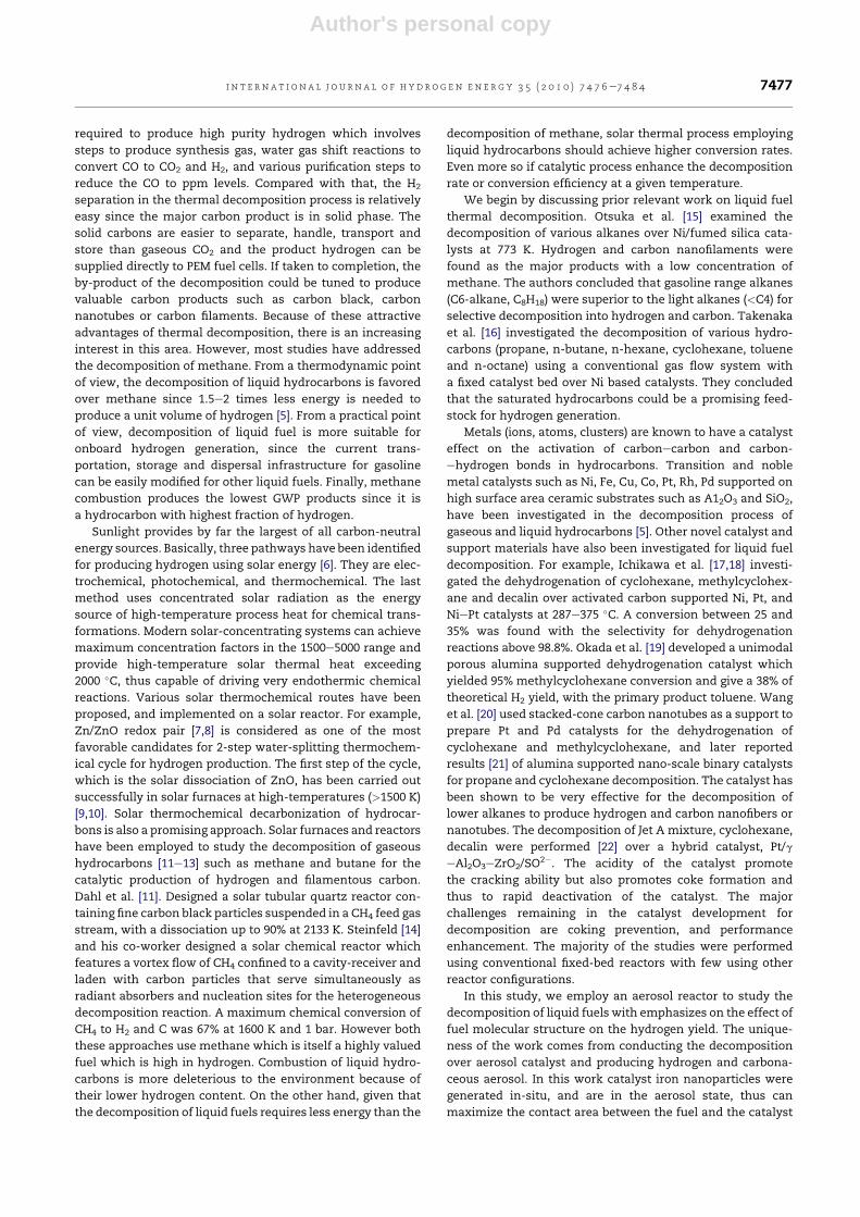
Fig. 1 e Hydrogen yields from thermal decomposition of
fuels (a) hydrogen yields from n-octane, iso-octane and 1-
octene (b) hydrogen yields from methylcyclohexane and
toluene.
i n t e rn a t i o n a l j o u r n a l o f h y d r o g e n en e r g y 3 5 ( 2 0 1 0 ) 7 4 7 6e7 4 8 47478
Author's personal copy
was used as the representing aromatic hydrocarbon and
methylcyclohexane (SigmaeAldrich, ReagentPlus, 99%) which
differs with toluene only in the benzene ring was selected as
the representing cycloalkane. The physical properties of the
fuels are listed in Table 1.
3. Results and discussion
3.1. Hydrogen yield from thermal decomposition ofdifferent liquid fuels
To investigate the effect of fuel molecular structure on the
hydrogen generation, thermal decomposition of different
hydrocarbons were performed under the same experiment
condition, and hydrogen yield for each fuel were calculated as
a function of decomposition temperature based on the
following equation:
YH2¼ XH2
VinZexpansion
a$V1mole$rfuel;in
where YH2is the hydrogen yield, XH2
is the hydrogen mole
fraction in the gaseous product, Vin is the input flow rate,
Zexpansionis the gaseous expansion factor determined from
the change of argon partial pressure, a is the stoichiometric
factor for complete conversion of a particular fuel to
hydrogen, V1mole is the volume of 1 mole ideal gas at room
temperature and rfuel,in is the fuel injection rate in moles per
minute, which was determined by measuring the mass
change of the liquid fuel before and after each experiment
run. Using the above equation, the hydrogen yields from pure
thermal decomposition of different liquid hydrocarbons were
calculated and shown in Fig. 1.
As we can see from the plots, except for toluene, all other
fuels start to release hydrogen at around 600 �C. For toluene,the onset temperature of hydrogen generation is about 800 �C,which reflects the greater stability of aromatic structures. The
general trend of ease of thermal decomposition is
alkanes > alkenes and cycloalkanes > aromatics. Compared
with the three fuels in Fig. 1(a), (These fuels have the same
carbon number and differ only in the carbon skeleton and
bond order) n-octane has the highest hydrogen yield and both
n-octane and iso-octane outperform their alkene counterpart
(1-octene) in terms of hydrogen yield. However, different from
the thermal cracking in petrochemical industry, where
branched hydrocarbons are always found to be more reactive
than their straight-chain counterparts [24], the straight-chain
n-octane outperforms its branched-chain counterpart (iso-
octane) in hydrogen production. Since carbonecarbon bond
scission is the principal reaction during cracking, while
hydrogen generation is more related to the CeH bond
strength, a comparison of the CeH bond configurations in the
three fuels may reveal some insights about trend in overall
hydrogen yield. Table 2 shows the number of each CeH bond
type, bond dissociation energy, and the percentage of total
CeH bonds in n-octane, iso-octane and 1-octene molecules.
Clearly, iso-octane has the highest percentage of CeH primary
bonds, and n-octane has the highest percentage of secondary
CeH bonds. Even though iso-octane has one tertiary CeH
bond which is the easiest to dissociate, the fact that the
majority of CeH bonds in iso-octane are primary CeH bonds
means it’s harder to decompose than n-octane. As for
1-octene, the existence of three HeC]C bonds makes it
extremely hard to decompose since the hydrogen atom
attached to the C]C double bond has much higher bond
dissociation energy (460 kJ/mol).
The comparison between toluene and methylcyclohexane
is straight forward. Since the dehydrogenation product of
toluene is methylcyclohexane, and this reaction is highly
endothermic (The heat of reaction is around 205 kJ/mol [19]).
Toluene is clearly harder to decompose. As we can see from
Fig. 1(b), not only the onset temperature of hydrogen genera-
tion for toluene is higher than that of methylcyclohexane, but
also the hydrogen yield from toluene is lower than that of
methylcyclohexan at all decomposition temperatures.
The order of overall hydrogen yield from thermal
decomposition of different fuels follows: n-octane > methyl-
cyclohexane > iso-octane > 1-octene > toluene. As a tenta-
tive explanation, the observed hydrogen yield order is
compared with the fuel cetane number which characterizes
the fuel ignition delay property. Table 3 lists the cetane
Table 2 e CeH bond types in n-octane, iso-octane and 1-octene.
Number of primaryCeH bond (bond
dissociation energy410 kJ/mol)
Number of secondaryCeH bond (bond
dissociationenergy 397 kJ/mol)
Number of tertiaryCeH bond (bond
dissociation energy389 kJ/mol)
Number of HeC]Cbond (bond dissociation
energy 460 kJ/mol)
n-octane 6 (33.3% of the total
CeH bonds)
12 (66.7% of the total
CeH bonds)
0 0
iso-octane 15 (83.3% of the total
CeH bonds)
2 (11.3% of the total
CeH bonds)
1 (5.3% of the total
CeH bonds)
0
1-octene 3 (18.75% of the total
CeH bonds)
10 (62.5% of the total
CeH bonds)
0 3 (18.75% of the total
CeH bonds)
Table 3 e Fuel cetane number.
Fuels Fuel Cetane Numbera
n-octane 63.8, 64.4, 65
Methylcyclohexane 20, 23
iso-octane 12, 14, 17.5
Toluene 5, 9, 18.3
1-octene 40.5, 41
a The different values of fuel cetane number are obtained by using
different methods.
i n t e r n a t i o n a l j o u r n a l o f h y d r o g e n en e r g y 3 5 ( 2 0 1 0 ) 7 4 7 6e7 4 8 4 7479
Author's personal copy
numbers for fuels investigated in this study. As we can see
from the table, except for 1-octene, the larger the cetane
number, the higher the hydrogen yields from thermal
decomposition. The cetane number characterizes the ease of
ignition for a given fuel.
3.2. Gaseous products from thermal decomposition ofliquid fuels
Mass spectrums of thermal decomposition product were
taken at each reaction temperature using the quadruple mass
analyzer. The common decomposition products for all the
fuels were hydrogen, toluene, benzene, and methane. For n-
octane, the product also contained C2 and C3 olefins; for iso-
octane, the product contained C2eC6 olefins; for 1-octene, the
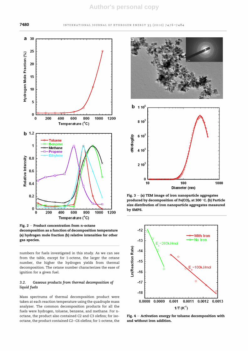
Fig. 2 e Product concentration from n-octane
decomposition as a function of decomposition temperature
(a) hydrogen mole fraction (b) relative intensities for other
gas species.
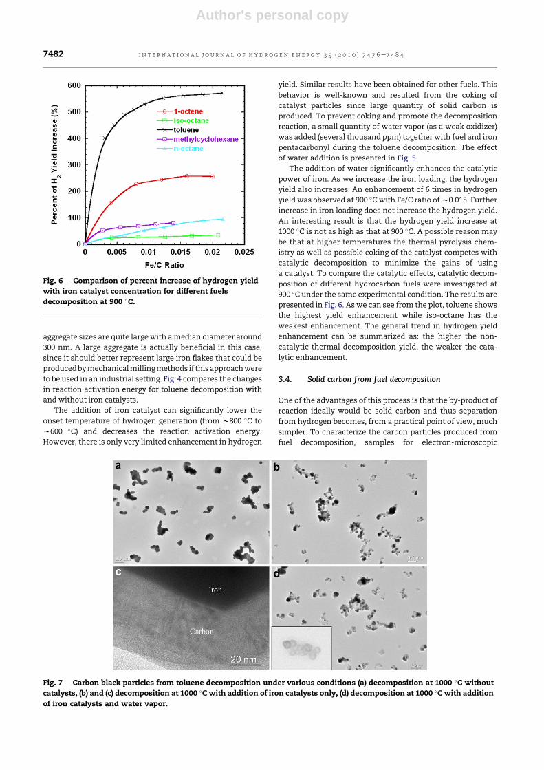
Fig. 3 e (a) TEM image of iron nanoparticle aggregates
produced by decomposition of Fe(CO)5 at 300 �C. (b) Particlesize distribution of iron nanoparticle aggregates measured
by SMPS.
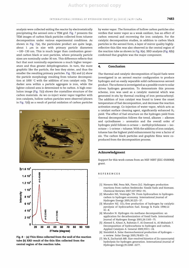
Fig. 4 e Activation energy for toluene decomposition with
and without iron addition.
i n t e rn a t i o n a l j o u r n a l o f h y d r o g e n en e r g y 3 5 ( 2 0 1 0 ) 7 4 7 6e7 4 8 47480

Author's personal copy
product had C2eC3 olefins and alkynes; for methylcyclohex-
ane, the product had C2eC3 olefins and paraffins and for
toluene, the product contained C2eC6 paraffins. The simi-
larity in gaseous products from different fuels suggests that at
high-temperatures, it is the stability of each gas species that
determines the product distribution. Fig. 2(a) and (b) shows
species concentration from n-octane decomposition as
a function of decomposition temperature. From these plots,
we can obtain some qualitative insights into the mechanism
of fuel decomposition.
Aswe can see from theplot, hydrogenpartial pressure starts
to increase at w600 �C accompanying by the increases in
concentration of toluene, methane, ethylene and other gas
species. The cracking of the fuel molecule is believed to be
initiated by carbonecarbon bond homolysis reaction with the
formation of two radicals. The intermediate radicals may
undergo carbonecarbon bond homolysis (b-scission) to form
olefins (ethylene and propene) and a new radical [25,26]. A
stepwise dehydrocyclization with gradual loss of hydrogen to
form a conjugated triene followed by ring closure and further
dehydrogenation may account for aromatics formation [25].
Therefore, toluene and benzene are produced from their
cycloalkane precursors. Studies have shown that the conver-
sion efficiency for preparing toluene from its precursor is nearly
100%, while for benzene this efficiency is lower [25]. At higher
temperatures, toluene hydrodealkylation reaction converts
toluene to benzene. As Fig. 2(b) shows, toluene concentration
peaks at 750 �C,while benzene concentrationpeaksat 900 �C.Ateven higher temperatures, benzene decomposition reaction
takes over the benzene formation reaction. Methane due to its
high stability peaks at 900 �C followed by ethylene at 750 �C, andpropene peaks at 600 �C. The decrease in temperature for the
peak concentration from methane to ethylene reflects the
decrease in thermal stability also reflects the hierarchy of
decomposition from larger to smaller molecules.
3.3. Catalytic decomposition of liquid fuels
Metal atomsare believed tohavean impact on the activation of
carbon-hydrogen and carbonecarbon bonds in hydrocarbons.
Reactions initialed by addition of metal atoms across a CeH or
CeC bond, results in loss of molecular hydrogen and small
alkanes toyieldmetal ioneolefincomplexes.Transitionmetals
are shown to have higher potential in catalyzing this reaction.
In our experiment, we produced catalytic iron nanoparticles
on-the-fly by thermally cracking the iron pentacarbonyl
precursor as discussed in the experimental section. TEM image
of the as-produced iron particles are presented in Fig. 3(a) and
shows that the primary particles are 10e20 nm in diameter,
with electron diffraction confirming elemental iron. The
particle size distribution of the catalytic iron particles was
measured using an SMPS (scanning mobility particle sizer)
system and is presented in Fig. 3(b). The results show that the
Fig. 5 e Adding water together with fuel and iron precursor
greatly enhances the catalytic effect of iron nanoparticles
in decomposition of toluene (a) percent of hydrogen yield
increase at 900 �C (b) percent of hydrogen yield increase at
1000 �C (c) absolute hydrogen yield for catalytic toluene
decomposition (the data points on the y-axis
corresponding to toluene thermal decomposition without
catalysts).
i n t e r n a t i o n a l j o u r n a l o f h y d r o g e n en e r g y 3 5 ( 2 0 1 0 ) 7 4 7 6e7 4 8 4 7481
Author's personal copy
aggregate sizes are quite large with amedian diameter around
300 nm. A large aggregate is actually beneficial in this case,
since it should better represent large iron flakes that could be
producedbymechanicalmillingmethods if this approachwere
to be used in an industrial setting. Fig. 4 compares the changes
in reaction activation energy for toluene decomposition with
and without iron catalysts.
The addition of iron catalyst can significantly lower the
onset temperature of hydrogen generation (from w800 �C to
w600 �C) and decreases the reaction activation energy.
However, there is only very limited enhancement in hydrogen
yield. Similar results have been obtained for other fuels. This
behavior is well-known and resulted from the coking of
catalyst particles since large quantity of solid carbon is
produced. To prevent coking and promote the decomposition
reaction, a small quantity of water vapor (as a weak oxidizer)
was added (several thousand ppm) together with fuel and iron
pentacarbonyl during the toluene decomposition. The effect
of water addition is presented in Fig. 5.
The addition of water significantly enhances the catalytic
power of iron. As we increase the iron loading, the hydrogen
yield also increases. An enhancement of 6 times in hydrogen
yield was observed at 900 �Cwith Fe/C ratio ofw0.015. Further
increase in iron loading does not increase the hydrogen yield.
An interesting result is that the hydrogen yield increase at
1000 �C is not as high as that at 900 �C. A possible reason may
be that at higher temperatures the thermal pyrolysis chem-
istry as well as possible coking of the catalyst competes with
catalytic decomposition to minimize the gains of using
a catalyst. To compare the catalytic effects, catalytic decom-
position of different hydrocarbon fuels were investigated at
900 �C under the same experimental condition. The results are
presented in Fig. 6. As we can see from the plot, toluene shows
the highest yield enhancement while iso-octane has the
weakest enhancement. The general trend in hydrogen yield
enhancement can be summarized as: the higher the non-
catalytic thermal decomposition yield, the weaker the cata-
lytic enhancement.
3.4. Solid carbon from fuel decomposition
One of the advantages of this process is that the by-product of
reaction ideally would be solid carbon and thus separation
from hydrogen becomes, from a practical point of view, much
simpler. To characterize the carbon particles produced from
fuel decomposition, samples for electron-microscopic
Fig. 6 e Comparison of percent increase of hydrogen yield
with iron catalyst concentration for different fuels
decomposition at 900 �C.
Fig. 7 e Carbon black particles from toluene decomposition under various conditions (a) decomposition at 1000 �C without
catalysts, (b) and (c) decomposition at 1000 �Cwith addition of iron catalysts only, (d) decomposition at 1000 �Cwith addition
of iron catalysts and water vapor.
i n t e rn a t i o n a l j o u r n a l o f h y d r o g e n en e r g y 3 5 ( 2 0 1 0 ) 7 4 7 6e7 4 8 47482
Author's personal copy
analysis were collected exiting the reactor by electrostatically
precipitating the aerosol onto a TEM grid. Fig. 7 presents the
TEM images of carbon black particles collected from toluene
decomposition under various experimental conditions. As
shown in Fig. 7(a), the particulate product are quite large,
about 1 mm in size with primary particle diameters
w100e130 nm. This is much larger than combustion gener-
ated carbon black or soot particles, where primarily particle
sizes are nominally under 30 nm. This difference reflects that
fact that soot nominally experiences a much higher temper-
ature and thus greater dehydrogenation. In turn, the more
graphitic like the particle, the less they sinter, and thus the
smaller the resulting primary particles. Fig. 7(b) and (c) show
the particle morphology resulting from toluene decomposi-
tion at 1000 �C with the addition of iron catalyst only. The
darker area within a particle aggregate is iron, while the
lighter-colored area is determined to be carbon. A high-reso-
lution image (Fig. 7(c)) shows the crystalline structure of the
carbon materials. As we co-inject water vapor together with
iron catalysts, hollow carbon particles were observed (shown
in Fig. 7(d)) as a result of partial oxidation of carbon particles
by water vapor. The formation of hollow carbon particles also
verifies that water vapor as a weak oxidizer, has an effect of
carbon removal and recovering the iron catalysts. For the
catalytic decomposition studies, in addition to carbon black
particles in the aerosol form, a layer of mirror quality highly-
reflective thin film was also observed in the central region of
the reaction tube as shown in Fig. 8(a). XRD analysis (Fig. 8(b))
confirmed that graphite was the major component.
4. Conclusion
The thermal and catalytic decomposition of liquid fuels were
investigated in an aerosol reactor configuration to produce
hydrogen and an easily separable solid carbonaceous aerosol
product. The scheme is investigated as a possible route to solar
driven hydrogen generation. To demonstrate this process
scheme, iron was used as a catalytic material which was
generated in-situ by thermal cracking of iron pentacarbonyl.
The addition of iron catalyst was found to lower the onset
temperature of fuel decomposition, and decrease the reaction
activation energy. Co-injection of water vapor, which acts as
a catalyst surface cleaning agent, significantly enhanced H2
yield. The effect of fuel structure on the hydrogen yield from
thermal decomposition follows the trend, alkanes > alkenes
and cycloalkanes > aromatics and the overall order of
hydrogen yield follows n-octane > methylcyclohexane > iso-
octane> 1-octene> toluene.With the addition of iron catalyst,
toluene has the highest yield enhancement by over a factor of
six. The carbon black particles and graphite films were co-
produced from the decomposition process.
Acknowledgment
Support for this work comes from an NSF-NIRT (EEC-0506968)
grant.
r e f e r e n c e s
[1] Navarro RM, Pena MA, Fierro JLG. Hydrogen productionreactions from carbon feedstocks: fossils fuels and biomass.Chemical Reviews 2007;107:3952e91.
[2] Muradov NZ, Veziroglu TN. From hydrocarbon to hydrogen-carbon to hydrogen economy. International Journal ofHydrogen Energy 2005;30:225e37.
[3] Muradov NZ. CO2-free production of hydrogen by catalyticpyrolysis of hydrocarbon fuel. Energy & Fuels 1998;12:41e8.
[4] Muradov N. Hydrogen via methane decomposition: anapplication for decarbonization of fossil fuels. InternationalJournal of Hydrogen Energy 2001;26:1165e75.
[5] Ahmed S, Aitani A, Rahman F, Al-Dawood A, Al-Muhaish F.Decomposition of hydrocarbons to hydrogen and carbon.Applied Catalysis A: General 2009;359:1e24.
[6] Steinfeld A. Solar thermochemical production of hydrogen e
a review. Solar Energy 2005;78:603e15.[7] Ma X, Zachariah MR. Size-resolved kinetics of Zn nanocrystal
hydrolysis for hydrogen generation. International Journal ofHydrogen Energy;35:2268e2277.
Fig. 8 e (a) Thin films collected from the wall of the reaction
tube (b) XRD result of the thin film collected from the
central region of the reaction tube.
i n t e r n a t i o n a l j o u r n a l o f h y d r o g e n en e r g y 3 5 ( 2 0 1 0 ) 7 4 7 6e7 4 8 4 7483

Author's personal copy
[8] Steinfeld A. Solar hydrogen production via a two-step water-splitting thermochemical cycle based on Zn/ZnO redoxreactions. International Journal of Hydrogen Energy 2002;27:611e9.
[9] Weidenkaff A, Reller A, Sibieude F, Wokaun A, Steinfeld A.Experimental investigations on the crystallization of zinc bydirect irradiation of zinc oxide in a solar furnace. Chemistryof Materials 2000;12:2175e81.
[10] Haueter P, Moeller S, Palumbo R, Steinfeld A. The productionof zinc by thermal dissociation of zinc oxide e solar chemicalreactor design. Solar Energy 1999;67:161e7.
[11] Dahl JK, Buechler KJ, Weimer AW, Lewandowski A,Bingham C. Solar-thermal dissociation of methane in a fluid-wall aerosol flow reactor. International Journal of HydrogenEnergy 2004;29:725e36.
[12] Meier A, Kirillov VA, Kuvshinov GG, Mogilnykh YI, Reller A,Steinfeld A, et al. Solar thermal decomposition ofhydrocarbons and carbon monoxide for the production ofcatalytic filamentous carbon. Chemical Engineering Science1999;54(15e16):3341e8.
[13] Steinfeld A, Kirillov V, Kuvshinov G, Mogilnykh Y, Reller A.Production of filamentous carbon and hydrogen bysolarthermal catalytic cracking of methane. ChemicalEngineering Science 1997;52:3599e603.
[14] Hirsch D, Steinfeld A. Solar hydrogen production by thermaldecomposition of natural gas using a vortex-flow reactor.International Journal of Hydrogen Energy 2004;29:47e55.
[15] Otsuka K, Shigeta Y, Takenaka S. Production of hydrogenfrom gasoline range alkanes with reduced CO2 emission.International Journal of Hydrogen Energy 2002;27:11e8.
[16] Takenaka S, Kawashima K, Matsune H, Kishida M.Production of CO-free hydrogen through the decompositionof LPG and kerosene over Ni-based catalysts. AppliedCatalysis A: General 2007;321:165e74.
[17] Biniwale RB, Kariya N, Ichikawa M. Dehydrogenation ofcyclohexane over Ni based catalysts supported on activated
carbon using spray-pulsed reactor and enhancement inactivity by addition of a small amount of Pt. Catalysis Letters2005;105:83e7.
[18] Kariya N, Fukuoka A, Utagawa T, Sakuramoto M, Goto Y,Ichikawa M. Efficient hydrogen production usingcyclohexane and decalin by pulse-spray mode reactor withPt catalysts. Applied Catalysis a-General 2003;247(2):247e59.
[19] Okada Y, Sasaki E, Watanabe E, Hyodo S, Nishijima H.Development of dehydrogenation catalyst for hydrogengeneration in organic chemical hydride method.International Journal of Hydrogen Energy 2006;31:1348e56.
[20] Wang YG, Shah N, Huffman GP. Pure hydrogen production bypartial dehydrogenation of cyclohexane andmethylcyclohexane over nanotube-supported Pt and Pdcatalysts. Energy & Fuels 2004;18:1429e33.
[21] Wang YG, Shah N, Huffman GP. Simultaneous production ofhydrogen and carbon nanostructures by decomposition ofpropane and cyclohexane over alumina supported binarycatalysts. Catalysis Today 2005;99:359e64.
[22] Wang TH, Zhu YF, Jiang Q. Size effect on evaporationtemperature of nanocrystals. Materials Chemistry andPhysics 2008;111:293e5.
[23] Karlsson MNA, Deppert K, Wacaser BA, Karlsson LS,Malm JO. Size-controlled nanoparticles by thermal crackingof iron pentacarbonyl. Applied Physics A: Materials Science &Processing 2005;80:1579e83.
[24] Kissin YV. Chemical mechanisms of catalytic cracking oversolid acidic catalysts: alkanes and alkenes. CatalysisReviews-Science and Engineering 2001;43:85e146.
[25] Olah GA. Hydrocarbon chemistry. John Wiley & Sons, Inc.;2003.
[26] Wojciechowski BW. The reaction mechanism of catalyticcracking: quantifying activity, selectivity, and catalystdecay. Catalysis Reviews-Science and Engineering 1998;40:209e328.
i n t e rn a t i o n a l j o u r n a l o f h y d r o g e n en e r g y 3 5 ( 2 0 1 0 ) 7 4 7 6e7 4 8 47484


![Journal of Power Sourcesnpt.pusan.ac.kr/sites/npt/download/[46]JPS-2015-HC decomp... · 2018-03-28 · versions of gas-fueled molten carbonate fuel cells (MCFC) or solid oxide fuel](https://static.fdocuments.in/doc/165x107/5f064ade7e708231d417432d/journal-of-power-46jps-2015-hc-decomp-2018-03-28-versions-of-gas-fueled.jpg)