2009 Special OEM Instrumentation … Special OEM Instrumentation Catalog Part #VSOC0908 (Supersedes...
29
2009 Special OEM Instrumentation Catalog www.vdo.com Part #VSOC0908 (Supersedes Part #SVSOC0907) • Measurement • Control • Monitoring
Transcript of 2009 Special OEM Instrumentation … Special OEM Instrumentation Catalog Part #VSOC0908 (Supersedes...

2009 Special OEMInstrumentation Catalog
www.vdo.com
Part #VSOC0908 (Supersedes Part #SVSOC0907)
• Measurement• Control• Monitoring

2 3
Analog Instruments
Vision Instruments
Vision Chrome Series . . . . . . . . . . . . . . . . . . . . . . . . . . . . . . . . . . . . 4–6
Vision Black Series . . . . . . . . . . . . . . . . . . . . . . . . . . . . . . . . . . . . . 7–11
Severe Duty Instruments
Severe Duty Chrome Series . . . . . . . . . . . . . . . . . . . . . . . . . . . . . 12–14
Severe Duty Black Series . . . . . . . . . . . . . . . . . . . . . . . . . . . . . . . 15–17
Cockpit International Instruments . . . . . . . . . . . . . . . . . . . . . . . . . . . 18–22
Series 1 Instruments. . . . . . . . . . . . . . . . . . . . . . . . . . . . . . . . . . . . . 23–26
Generic Analog Instrument Cluster Solutions . . . . . . . . . . . . . . . . . . . . . 27
Hourmeters. . . . . . . . . . . . . . . . . . . . . . . . . . . . . . . . . . . . . . . . . . . . . . . 28
CAN-based Instruments
CAN Severe Link. . . . . . . . . . . . . . . . . . . . . . . . . . . . . . . . . . . . . . . . . . . 29
CANcockpit Instrumentation System . . . . . . . . . . . . . . . . . . . . . . . . 30–31
Senders and Switches
Pressure Senders . . . . . . . . . . . . . . . . . . . . . . . . . . . . . . . . . . . . . . . 32–33
Temperature Senders . . . . . . . . . . . . . . . . . . . . . . . . . . . . . . . . . . . . 34–35
Heavy-Duty Pressure Switches. . . . . . . . . . . . . . . . . . . . . . . . . . . . . . . . 36
Temperature Switches . . . . . . . . . . . . . . . . . . . . . . . . . . . . . . . . . . . . . . 37
Fuel and Water Level Senders . . . . . . . . . . . . . . . . . . . . . . . . . . . . . 38–39
Speedometer and Tachometer Senders . . . . . . . . . . . . . . . . . . . . . . . . . 40
Instrument Accessories and Service Parts. . . . . . . . . . . . . . . . . . . . . 41–44
Light Bulbs and Sockets . . . . . . . . . . . . . . . . . . . . . . . . . . . . . . . . . . . 45–46
Technical Specifications and Dimensions . . . . . . . . . . . . . . . . . . . . . 47–53
Cross Reference . . . . . . . . . . . . . . . . . . . . . . . . . . . . . . . . . . . . . . . . . . 54–55
A heritage of engineering quality and innovation
We’re focused on providing our customers with the best possible instrumentation – a goal that we’ve pursued since 1920. We continue to work to deliver the functionality, durability, and high quality finish that have earned our products a best-in-class reputation, worldwide. At the same time, we strive to continually pursue innovations that make our instrumentation more efficient, affordable, and useful to the people who own and operate vehicles and equipment that feature our products.
While we’re aware of the vital role of our instruments as a human-machine interface and the importance of factors such as ergonomics, cost, and reliability, we haven’t neglected aesthetics. Our latest styles include Vision and Severe Duty instruments offered with bezels in either classic black or the new sleek, polished chrome.
In this catalog you'll find expanded line options, our latest technologies, complete accessories, and technical data. From rugged analog gauges to sophisticated, flexible CAN bus platforms, we’re working to give our customers choice, flexibility, and style for all their monitoring needs.

4
For technical specifications and dimensions, see pages 47–53.
5
For technical specifications and dimensions, see pages 47–53.
Programmable Speedometers w/ resettable LCD tripodometer Speedometer features push button odometer and trip odometer clearly displayed in the LCD window. Unique auto-calibration feature allows for easy adjustment and can
be used with Hall Effect and inductive senders or most electronic controlled transmissions outputs.
Single Pack 10 Pack Description Size Dwg Terminal Voltage Part No. Part No.
120 mph 3 3/8” (85mm) dia A .250" Spade 12 437 191 437 191B
Programmable Tachometers w/ LCD hourmeter Programmable for use with most engine electronic control ignitions with tachometer output terminal, standard coil ignition, alternator signal, and 12v
square wave applications. Non-resettable engine hourmeter is displayed in LCD window.
Single Pack 10 Pack Description Size Dwg Terminal Voltage Part No Part No.
3,000 RPM 3 3/8” (85mm) dia B .250" Spade 12 333 192 333 192B4,000 RPM 3 3/8” (85mm) dia B .250" Spade 12 333 193 333 193B6,000 RPM 3 3/8” (85mm) dia B .250" Spade 12 333 194 333 194B
Programmable Tachometers w/o hourmeter For use on 4,5,6,8 cylinder application engines with standard coil ignitions, most square wave electronic
control ignitions with tachometer output terminal, and alternators with "w' tachometer terminal.
Single Pack 10 Pack Description Size Dwg Terminal Voltage Part No. Part No.
3,000 RPM 3 3/8” (85mm) dia C .250" Spade 12 333 199 333 199B6,000 RPM 3 3/8” (85mm) dia C .250" Spade 12 333 197 333 197B
Vision Instruments
VDO Vision instruments deliver world-class accuracy, reliability, and technology at very competitive pricing. These precision instruments feature stepper motor technology or air core movements for smooth, accurate performance and long-life dependability. Our unique VDO Spin-LokTM mounting system makes installing Vision instruments fast and easy and provides a full 360 degrees of mounting force to prevent panel warping and gauge rotation.
Vision gauges incorporate easy-to-read white graphics on an illuminated black dial, and use red pointers featuring our exclusive TriopticTM illumination for maximum nighttime
visibility. Optional light diffusers allow the dial illumination color to be changed to red or green.
Vision line instruments are offered with bezels in either classic black or sleek, polished chrome.
Vision Chrome Series
Our new VDO Vision Chrome series is based on the popular and reliable Vision line. These instruments feature stylish, stain-resistant chrome bezels and offer the same robust platform, accuracy, and dependability as our original Vision black bezel instruments.
Fluid Temperature Gauges, electrical, 2 1/16” (52mm) dia Single Pack 10 Pack Description On Dial Dwg Terminal Sender Table Voltage Part No. Part No.
220o F “Water” E .250" Spade – 12 310 194 310 194B250o F “Water” E .250" Spade A 12 310 195 310 195B300o F “Oil” E .250" Spade B 12 310 196 310 196B
See pages 34–35 for temperature sender tables.
Fluid Temperature Gauge Kits, electrical, includes sender, 2 1/16” (52mm) dia Single Pack Description Thread Type On Dial Dwg Terminal Adapter Incl. Voltage Part No.
250o F US “Water” E .250" Spade 1/4", 3/8", 1/2" 12 310 1951250o F Metric “Water” E .250" Spade M10, M12, M14, M16, 1/8 BSP 12 310 1952300o F US “Oil” E .250" Spade 1/4", 3/8", 1/2" 12 310 1961300o F Metric “Oil” E .250" Spade M10, M12, M14, M16, 1/8 BSP 12 310 1962
Water Temperature Gauges, mechanical, 2 1/16” (52mm) dia Single Pack 10 Pack Description Length On Dial Dwg Fitting Size Voltage Part No. Part No.
265o F 72” “Water” H 1/2–14 NPT 12 180 191 180 191B265o F 96” “Water” H 1/2–14 NPT 12 180 192 180 192B
Adapters, for fluid temperature gauges, mechanical Single Pack Description Part No.1/2–14 NPT 180 0663/8–18 NPT 180 067
Pyrometers, electrical, 2 1/16” (52mm) dia 250o F–1650o F Single Pack 10 Pack Description Dwg Voltage Part No. Part No.
Complete kit with 12’ lead wire O 12 310 193 –Gauge only O 12 310 191 310 193BPyrometer sender only – – 323 892 –30’ extension wire – – 240 092 –
Oil Pressure Gauges, electrical, 2 1/16” (52mm) dia Single Pack 10 Pack Description Ohm Range On Dial Dwg Terminal Sender Table Voltage Part No. Part No.
80 PSI 10–180 “Oil” E .250" Spade 1 12 350 194 350 194B80 PSI 240–33 “Oil” E .250" Spade 2 12 350 195 350 195B100 PSI 10–180 “Oil” E .250" Spade 3 12 350 196 350 196B100 PSI 240–33 “Oil” E .250" Spade 4 12 350 197 350 197B150 PSI 10–180 “Oil” E .250" Spade 5 12 350 198 350 198B150 PSI 240–33 “Oil” E .250" Spade – 12 350 199 350 199B400 PSI 10–180 “Trans” E .250" Spade 7 12 350 290 350 290B
See pages 32–33 for pressure sender tables.
Vision Instruments
Vision Chrome Series

7
For technical specifications and dimensions, see pages 47–53.
6
For technical specifications and dimensions, see pages 47–53.
Oil Pressure Gauge Kits, electrical, includes sender, 2 1/16” (52mm) dia Single Pack Description Thread Type Adapter Incl. On Dial Dwg Terminal Voltage Part No.
80 PSI US 1/4", 3/8", 1/2" “Oil” E .250" Spade 12 350 194180 PSI Metric M10, M12, M14, M16, 1/8 BSP “Oil” E .250" Spade 12 350 1942100 PSI US 1/4", 3/8", 1/2" “Oil” E .250" Spade 12 350 1961100 PSI Metric M10, M12, M14, M16, 1/8 BSP “Oil” E .250" Spade 12 350 1962150 PSI US 1/4", 3/8", 1/2" “Oil” E .250" Spade 12 350 1981150 PSI Metric M10, M12, M14, M16, 1/8 BSP “Oil” E .250" Spade 12 350 1982
Boost Pressure Gauges, mechanical, 2 1/16” (52mm) dia Single Pack 10 Pack Description On Dial Dwg Fitting Size Voltage Part No. Part No.
15 PSI “Boost” I 1/8–27NPT 12 150 191 150 191B30 PSI “Boost” I 1/8–27NPT 12 150 194 150 194B
Tubing kit not included, see page 41.
Oil Pressure Gauges, mechanical, 2 1/16” (52mm) dia Single Pack 10 Pack Description On Dial Dwg Fitting Size Voltage Part No. Part No.
100 PSI “Oil” I 1/8–27NPT 12 150 197 150 197B150 PSI “Oil” I 1/8–27NPT 12 150 192 150 192B
Tubing kit not included, see page 41.
Boost Pressure Gauge Kits, mechanical, includes 6ft of tubing & adapters, 2 1/16” (52mm) dia
Single Pack Description Thread Type On Dial Dwg Adapters Incl. Voltage Part No.
15 PSI US “Boost” I 1/4", 3/8", 1/2" 12 150 191115 PSI Metric “Boost” I M10, M12, M14, M16, 1/8 BSP 12 150 1912 30 PSI US “Boost” I 1/4", 3/8", 1/2" 12 150 194130 PSI Metric “Boost” I M10, M12, M14, M16, 1/8 BSP 12 150 1942
Oil Pressure Gauge Kits, mechanical, includes 6ft of tubing & adapters, 2 1/16” (52mm) dia Single Pack Description Thread Type On Dial Dwg Adapters Incl. Voltage Part No.
100 PSI US “Oil” I 1/4", 3/8", 1/2" 12 150 1971100 PSI Metric “Oil” I M10, M12, M14, M16, 1/8 BSP 12 150 1972150 PSI US “Oil” I 1/4", 3/8", 1/2" 12 150 1921150 PSI Metric “Oil” I M10, M12, M14, M16, 1/8 BSP 12 150 1922
Fuel Level Gauges, electrical, 2 1/16” (52mm) dia Single Pack 10 Pack Description Ohm Range On Dial Dwg Terminal Sender Table Voltage Part No. Part No.
For VDO sender 10–180 “Fuel” E .250" Spade 9 12 301 194 301 194BFor U.S. sender 240–33 “Fuel” E .250" Spade 10 12 301 195 301 195BFor Tube Type 90–0 (ADJ) “Fuel” E .250" Spade 12 12 301 197 301 197B
See pages 38–39 for fuel level sender tables.
Voltmeters, 2 1/16” (52mm) dia Single Pack 10 Pack Description On Dial Dwg Fitting Size Voltage Part No. Part No.
8–16V “Volt” E .250" Spade 12 332 193 332 193B
Vision Instruments Vision Instruments
Programmable Speedometers w/ resettable LCD tripodometer Speedometer features push button odometer and trip odometer clearly displayed in the LCD window. Unique auto-calibration feature allows for easy adjustment and can
be used with Hall Effect and inductive senders or most electronic controlled transmissions outputs.
Single Pack 10 Pack Description Size Dwg Terminal Voltage Part No. Part No.
45 mph / 70 km/h 3 1/8" (80mm) dia A .250" Spade 12 437 160 437 160B120 mph 3 1/8" (80mm) dia A .250" Spade 12 437 151 437 151B140 mph / 220 km/h 3 1/8" (80mm) dia A .250" Spade 12 437 157 437 157B200 km/h 3 1/8" (80mm) dia A .250" Spade 12 437 154 437 154B85 mph / 130 km/h 3 3/8" (85mm) dia A .250" Spade 12 437 152 437 152B120 mph 3 3/8" (85mm) dia A .250" Spade 12 437 153 437 153B140 mph / 220 km/h 4" (100mm) dia A .250" Spade 12 437 158 437 158B200 km/h 4" (100mm) dia A .250" Spade 12 437 156 437 156B120 mph 4" (100mm) dia A .250" Spade 12 437 155 437 155B220 mph 4" (100mm) dia A .250" Spade 12 437 159 437 159B
Programmable Tachometers w/ LCD hourmeter Programmable for use with most engine electronic control ignitions with tachometer output terminal, standard coil ignition, alternator signal, and
12v square wave applications. Non-resettable engine hourmeter is displayed in LCD window.
Single Pack 10 Pack Description Size Dwg Terminal Voltage Part No. Part No.
3,000 RPM 3 3/8" (85mm) dia B .250" Spade 12 333 162 333 162B4,000 RPM 3 3/8" (85mm) dia B .250" Spade 12 333 163 333 163B6,000 RPM 3 3/8" (85mm) dia B .250" Spade 12 333 164 333 164B
Programmable Tachometers w/o LCD hourmeter For use on 4,5,6,8 cylinder application engines with standard coil ignitions, most square wave electronic
control ignitions with tachometer output terminal, and alternators with "w" tachometer terminal.
Single Pack 10 Pack Description Size Dwg Terminal Voltage Part No. Part No.
4,000 RPM 2 1/16" (52mm) dia D .250" Spade 12 333 156 333 156B6,000 RPM 2 1/16" (52mm) dia D .250" Spade 12 333 158 333 158B8,000 RPM 2 1/16" (52mm) dia D .250" Spade 12 333 159 333 159B7,000 RPM 3 1/8" (80mm) dia C .250" Spade 12 333 151 333 151B3,000 RPM 3 3/8" (85mm) dia C .250" Spade 12 333 152 333 152B7,000 RPM 3 3/8" (85mm) dia C .250" Spade 12 333 155 333 155B8,000 RPM 4" (100mm) dia C .250" Spade 12 333 160 333 160B
Vision Black Series

8
For technical specifications and dimensions, see pages 47–53.
9
For technical specifications and dimensions, see pages 47–53.
Vision Instruments Vision Instruments
Fluid Temperature Gauges, electrical, 2 1/16" (52mm) dia Single Pack 10 Pack Description On Dial Dwg Terminal Sender Table Voltage Part No. Part No.
220o F "Water" E .250" Spade – 12 310 104 310 104B250o F "Water" E .250" Spade A 12 310 105 310 105B300o F "Oil" E .250" Spade B 12 310 106 310 106B300o F "Trans" E .250" Spade B 12 310 111 310 111B400o F "Trans" E .250" Spade C 12 310 107 310 107B120o C "Water" E .250" Spade A 12 310 108 310 108B150o C "Oil" E .250" Spade B 12 310 109 310 109B
See pages 34–35 for temperature sender tables.
Fluid Temperature Gauge Kits, electrical, includes sender, 2 1/16" (52mm) dia Single Pack Description Thread Type On Dial Dwg Terminal Adapters Incl. Voltage Part No.
250o F US "Water" E .250" Spade 1/4", 3/8", 1/2 12 310 1051250o F Metric "Water" E .250" Spade M10, M12, M14, M16, 1/8 BSP 12 310 1052300o F US "Oil" E .250" Spade 1/4", 3/8", 1/2 12 310 1061300o F Metric "Oil" E .250" Spade M10, M12, M14, M16, 1/8 BSP 12 310 1062400o F US "Trans" E .250" Spade 1/4", 3/8", 1/2 12 310 1071400o F Metric "Trans" E .250" Spade M10, M12, M14, M16, 1/8 BSP 12 310 1072
Fluid Temperature Gauges, mechanical, 2 1/16" (52mm) dia Single Pack 10 Pack Description Length On Dial Dwg Fitting Size Voltage Part No. Part No.
265o F 72" "Water" H 1/2–14 NPT 12 180 101 180 101B340o F 72" "Oil" H 1/2–14 NPT 12 180 105 180 105B
Adapters, for fluid temperature gauges, mechanical Single Pack Description Part No.1/2–14 NPT 180 0663/8–18 NPT 180 067
Outside Temperature Gauges, electrical, 2 1/16" (52mm) dia Single Pack 10 Pack Description On Dial Dwg Voltage Part No. Part No.
Complete Kit, Fahrenheit -10o F–120o F "oF" N 12 397 154 397 154BComplete Kit, Celsius -25o C–40o C "oC" N 12 397 155 397 155B
Pyrometers, electrical, 2 1/16" (52mm) dia, 250o F–1650o F Single Pack 10 Pack Description On Dial Dwg Voltage Part No. Part No.
Complete kit with 12' lead wire "oF" O 12 310 153 –Gauge only "oF" O 12 310 151 310 151BPyrometer sender only – O – 323 892 –30' extension wire – – – 240 092 –
Oil Pressure Gauges, electrical, 2 1/16" (52mm) dia Single Pack 10 Pack Description Ohm Range On Dial Dwg Terminal Sender Table Voltage Part No. Part No.
80 PSI 10–180 "Oil" E .250" Spade 1 12 350 104 350 104B80 PSI 240–33 "Oil" E .250" Spade 2 12 350 105 350 105B100 PSI 10–180 "Oil" E .250" Spade 3 12 350 106 350 106B100 PSI 240–33 "Oil" E .250" Spade 4 12 350 107 350 107B150 PSI 10–180 "Oil" E .250" Spade 5 12 350 108 350 108B150 PSI 240–33 "Oil" E .250" Spade – 12 350 109 350 109B400 PSI 10–180 "Trans" E .250" Spade 7 12 350 110 350 110B5 bar 10–180 Oil Symbol E .250" Spade 1 12 350 101 350 101B10 bar 10–180 Oil Symbol E .250" Spade 5 12 350 102 350 102B
See pages 32–33 for pressure sender tables.
Oil Pressure Gauge Kits, electrical, includes sender, 2 1/16" (52mm) dia, 250o F–1650o F Single Pack Description Thread Type On Dial Dwg Terminal Adapters Incl. Voltage Part No.
80 PSI US "Oil" E .250" Spade 1/4", 3/8", 1/2 12 350 104180 PSI Metric "Oil" E .250" Spade M10, M12, M14, M16, 1/8 BSP 12 350 1042100 PSI US "Oil" E .250" Spade 1/4", 3/8", 1/2 12 350 1061100 PSI Metric "Oil" E .250" Spade M10, M12, M14, M16, 1/8 BSP 12 350 1062150 PSI US "Oil" E .250" Spade 1/4", 3/8", 1/2 12 350 1081150 PSI Metric "Oil" E .250" Spade M10, M12, M14, M16, 1/8 BSP 12 350 1082
Air Pressure Gauges, electrical, 2 1/16" (52mm) dia Single Pack 10 Pack Description Ohm Range On Dial Dwg Terminal Sender Table Voltage Part No. Part No.
150 PSI 10–180 "Front Air" E .250" Spade 5 12 350 111 350 111B150 PSI 10–180 "Rear Air" E .250" Spade 5 12 350 112 350 112B
See pages 32–33 for pressure sender tables.
Oil Pressure Gauges, mechanical, 2 1/16" (52mm) dia Single Pack 10 Pack Description On Dial Dwg Fitting Size Voltage Part No. Part No.
100 PSI "Oil" I 1/8–27NPT 12 150 107 150 107B150 PSI "Oil" I 1/8–27NPT 12 150 111 150 111B
Tubing kit not included, see page 41.

10
For technical specifications and dimensions, see pages 47–53.
Oil Pressure Gauge Kits, mechanical, includes 6ft of tubing & adapters, 2 1/16" (52mm) dia
Single Pack Description Thread Type On Dial Dwg Adapters Incl. Voltage Part No.
100 PSI US "Oil" I 1/4", 3/8", 1/2 12 150 1071100 PSI Metric "Oil" I M10, M12, M14, M16, 1/8 BSP 12 150 1072150 PSI US "Oil" I 1/4", 3/8", 1/2 12 150 1111150 PSI Metric "Oil" I M10, M12, M14, M16, 1/8 BSP 12 150 1112
Air Pressure Gauges, mechanical, 2 1/16" (52mm) dia Single Pack 10 Pack Description On Dial Dwg Fitting Size Voltage Part No. Part No.
150 PSI "Front Air" I 1/8–27NPT 12 150 105 150 105B150 PSI "Rear Air" I 1/8–27NPT 12 150 106 150 106B150 PSI "Air" I 1/8–27NPT 12 150 112 150 112B
Turbo & Boost Gauges, mechanical, 2 1/16" (52mm) dia Single Pack 10 Pack Description On Dial Dwg Fitting Size Voltage Part No. Part No.
15 PSI "Boost" I 1/8–27NPT 12 150 101 150 101B30 PSI "Boost" I 1/8–27NPT 12 150 104 150 104B0–30 in Hg to 0–25 PSI "Turbo" I 1/8–27NPT 12 150 121 150 121B0–3 bar "Boost" I 1/8–27NPT 12 150 102 150 102B
Tubing kit not included, see page 41.
Turbo & Boost Gauge Kits, mechanical, includes 6ft of tubing & adapters, 2 1/16" (52mm) dia Single Pack Description Thread Type On Dial Dwg Adapters Incl. Voltage Part No.
15 PSI US "Boost" I 1/4", 3/8", 1/2 12 150 101115 PSI Metric "Boost" I M10, M12, M14, M16, 1/8 BSP 12 150 101230 PSI US "Boost" I 1/4", 3/8", 1/2 12 150 104130 PSI Metric "Boost" I M10, M12, M14, M16, 1/8 BSP 12 150 10420–30 in Hg to 0–25 PSI US "Turbo" I 1/4", 3/8", 1/2 12 150 12110–30 in Hg to 0–25 PSI Metric "Turbo" I M10, M12, M14, M16, 1/8 BSP 12 150 1212
Fuel Level Gauges, electrical, 2 1/16" (52mm) dia Single Pack 10 Pack Description Ohm Range On Dial Dwg Sender Table Voltage Part No. Part No.
For VDO sender 10–180 "Fuel" E 9 12 301 104 301 104BFor U.S. sender 240–33 "Fuel" E 10 12 301 105 301 105BFor GM sender (from 1965) 0–90 "Fuel" E 11 12 301 106 301 106BFor tube type sender 90–0 (ADJ) "Fuel" E 12 12 301 107 301 107B
See pages 38–39 for fuel level sender tables.
Vision Instruments Vision Instruments
Vacuum Gauge, mechanical, 2 1/16" (52mm) dia Single Pack 10 Pack Description On Dial Dwg Fitting Size Voltage Part No. Part No.
0–30 in Hg "Vacuum" I 1/8–27 NPT 12 150 131 150 131BTubing kit not included, see page 41.
Voltmeter, 2 1/16" (52mm) dia Single Pack 10 Pack Description On Dial Dwg Terminal Voltage Part No. Part No.
8–16V "Volt" E .250" Spade 12 332 103 332 103B
Ammeters (non-shunted), electrical, 2 1/16" (52mm) dia Single Pack 10 Pack Description Range On Dial Dwg Terminal Voltage Part No. Part No.
30 Amp 30 / 0 / 30 "Amp" L Stud 12 190 103 190 103B60 Amp 60 / 0 / 60 "Amp" L Stud 12 190 104 190 104B100 Amp 100 / 0 / 100 "Amp" L Stud 12 190 105 190 105B
Clocks, electrical, 2 1/16" (52mm) dia Single Pack 10 Pack Description Range On Dial Dwg Terminal Voltage Part No. Part No.
Analog 9–28V – J .250" Spade 12 / 24 370 155 370 155BQuartz, Adjuster on dial – – – .250" Spade 12 / 24 370 100 –
11
For technical specifications and dimensions, see pages 47–53.

12
For technical specifications and dimensions, see pages 47–53.
13
For technical specifications and dimensions, see pages 47–53.
Severe Duty Instruments
Programmable Tachometers w/ LCD hourmeterProgrammable for use with most engine electronic control ignitions with tachometer output terminal, standard coil ignition, alternator signal, and 12v square wave applications.
Non-resettable engine hourmeter is displayed in LCD window.
Single Pack 10 Pack Description Size Dwg Terminal Voltage Part No. Part No.
4,000 RPM 3 3/8" (85mm) dia R .250" Spade 12 / 24 3334105 3334105B6,000 RPM 3 3/8" (85mm) dia R .250" Spade 12 / 24 3334106 3334106B
Programmable Tachometers w/o hourmeterFor use on 4,5,6,8 cylinder application engines with standard coil ignitions, most square wave electronic control ignitions
with tachometer output terminal, and alternators with "w" tachometer terminal.
Single Pack 10 Pack Description Size Dwg Terminal Voltage Part No. Part No.
4,000 RPM 3 3/8" (85mm) dia S .250" Spade 12 3334102 3334102B6,000 RPM 3 3/8" (85mm) dia S .250" Spade 12 3334101 3334101B
When an extreme working environment calls for a tough gauge, VDO Severe Duty instruments get the job done. Specially designed for industrial applications, these instruments are CE certified and incorporate our patented air core movements or stepper motor technology.
For maximum protection against the elements, Severe Duty instruments are made with corrosion-proof materials, silver contact connectors, and highly impact-resistant plastic lenses. A dual lens system prevents gauge fogging and contoured lenses minimize reflections, making Severe Duty instruments readable in almost any environment.
Severe Duty instruments are warning light capable and are
available in 12/24-volt applications. The dials are backlit using TriopticTM illumination for optimum readability day or night. Our Spin-LokTM mounting system makes for fast, secure installation – perfect for hassle-free retrofitting.
Available in a choice of black or chrome round bezels, Severe Duty instruments can also be adapted to a square bezel gauge by using an accessory kit (sold separately).
Severe Duty Chrome Series
Our new Severe Duty Chrome instruments feature polished chrome finish bezels and offer all of the benefits of the Severe Duty line.
Fluid Temperature Gauges, electrical, 2 1/16" (52mm) dia Single Pack 10 Pack Description On Dial Dwg Terminal Sender Table Voltage Part No. Part No.
240o F / 100o C Water Symbol T .250" Spade A 12 3104101 3104101B250o F / 120o C Water Symbol T .250" Spade A 12 3104103 3104103B250o F / 120o C Water Symbol T .250" Spade A 24 3104104 3104104B300o F / 150o C Oil Symbol T .250" Spade B 12 3104108 3104108B300o F / 150o C Oil Symbol T .250" Spade B 24 3104109 3104109B400o F Gear Symbol T .250" Spade C 12 3104107 3104107B
See pages 34–35 for temperature sender tables. Note: Warning lights must be ordered separately.
Pyrometer, electrical, 2 1/16" (52mm) dia, 250o F–1650o F Single Pack Description Dwg Voltage Part No.
Complete Kit with 13' extension wire V 12 3104106Pyrometer sender only 326 00113' extension wire 326 002
Oil Pressure Gauges, electrical, 2 1/16" (52mm) dia Single Pack 10 Pack Description Ohm Range On Dial Dwg Terminal Sender Table Voltage Part No. Part No.
80 PSI / 5 bar 10–180 Oil Symbol T .250" Spade 1 12 3504103 3504103B80 PSI / 5 bar 10–180 Oil Symbol T .250" Spade 1 24 3504104 3504104B80 PSI / 5 bar 240–33 Oil Symbol T .250" Spade 2 12 3504121 3504121B100 PSI / 7 bar 240–33 Oil Symbol T .250" Spade 4 12 3504101 3504101B150 PSI / 10 bar 10–180 Oil Symbol T .250" Spade 5 12 3504105 3504105B150 PSI / 10 bar 10–180 Oil Symbol T .250" Spade 5 24 3504106 3504106B150 PSI / 10 bar 240–33 Oil Symbol T .250" Spade – 12 3504107 3504107B150 PSI / 10 bar 240–33 Oil Symbol T .250" Spade – 24 3504108 3504108B400 PSI / 28 bar 10–180 Oil Symbol T .250" Spade 7 12 3504109 3504109B400 PSI / 28 bar 10–180 Oil Symbol T .250" Spade 7 24 3504110 3504110B
See pages 32–33 for pressure sender tables. Note: Warning lights must be ordered separately.
Fuel Level Gauges, electrical, 2 1/16" (52mm) dia Single Pack 10 Pack Description Ohm Range On Dial Dwg Terminal Sender Table Voltage Part No. Part No.
For VDO sender 10–180 Fuel Symbol T .250" Spade 9 12 3014103 3014103BFor VDO sender 10–180 Fuel Symbol T .250" Spade 9 24 3014104 3014104BFor U.S. sender 240–33 Fuel Symbol T .250" Spade 10 12 3014101 3014101BFor U.S. sender 240–33 Fuel Symbol T .250" Spade 10 24 3014102 3014102BFor tube type sender 90–0 (ADJ) Fuel Symbol T .250" Spade 12 12 3014105 3014105BFor tube type sender 90–0 (ADJ) Fuel Symbol T .250" Spade 12 24 3014106 3014106B
See pages 38–39 for fuel level sender tables. Note: Warning lights must be ordered separately.
Water Level Gauges, electrical, 2 1/16" (52mm) dia Single Pack 10 Pack Description Ohm Range On Dial Dwg Terminal Sender Table Voltage Part No. Part No.
Water 10–180 Water Symbol T .250" Spade 13 12 3014109 3014109BWater 10–180 Water Symbol T .250" Spade 13 24 3014121 3014121B
See pages 38–39 for water level sender tables. Note: Warning lights must be ordered separately.
Severe Duty Instruments
Severe Duty Chrome Series
13

14
For technical specifications and dimensions, see pages 47–53.
15
For technical specifications and dimensions, see pages 47–53.
Voltmeters, 2 1/16" (52mm) dia Single Pack 10 Pack Description On Dial Dwg Terminal Voltage Part No. Part No.
8–16V Battery Symbol T .250" Spade 12 3324101 3324101B18–32V Battery Symbol T .250" Spade 24 3324102 3324102B
Note: Warning lights must be ordered separately.
Ammeters, 2 1/16" (52mm) dia Single Pack 10 Pack Description Range On Dial Dwg Terminal Voltage Part No. Part No.
80A, gauge only 80 / 0 / 80 AMP W .250" Spade 12 / 24 1904101 1904101B140A, gauge only 140 / 0 / 140 AMP W .250" Spade 12 / 24 1904102 1904102B80A, shunt only 391 010140A, shunt only 391 011
Clocks, 2 1/16" (52mm) dia Single Pack 10 Pack Description Range Terminal Voltage Part No. Part No.
Analog 9–28V .250" Spade 12 / 24 3704101 3704101B
Hourmeters, 2 1/16" (52mm) dia Single Pack 10 Pack Description Max Hours On Dial Dwg Terminal Voltage Part No. Part No.
Illuminated 10,000 "Engine Hours" U .250" Spade 12 / 24 3314101 3314101B
Optional In-Gauge Warning Lights Single Pack Description Terminal Voltage Part No.
For volt, temp, pressure and fuel .250" Spade 12 600 834For volt, temp, pressure and fuel .125" Spade 24 600 835
Programmable Tachometers w/ LCD hourmeterProgrammable for use with most engine electronic control ignitions with tachometer output terminal, standard coil ignition, alternator signal, and 12v square
wave applications. Non-resettable engine hourmeter is displayed in LCD window.
Single Pack Bulk Pack Description Size Dwg Terminal Voltage Part No. Part No.
3,000 RPM 3 3/8" (85mm) dia R .250" Spade 12 / 24 02 012 126D 02 012 1264,000 RPM 3 3/8" (85mm) dia R .250" Spade 12 / 24 3331105 02 012 1506,000 RPM 3 3/8" (85mm) dia R .250" Spade 12 / 24 3331106 3331106B
Programmable Tachometers w/o hourmeterFor use on 4,5,6,8 cylinder application engines with standard coil ignitions, most square wave electronic
control ignitions with tachometer output terminal, and alternators with "w" tachometer terminal.
Single Pack Bulk Pack Description Size Dwg Terminal Voltage Part No. Part No.
3,000 RPM 3 3/8" (85mm) dia S .250" Spade 12 02 012 426D 02 012 4264,000 RPM 3 3/8" (85mm) dia S .250" Spade 12 3331102 02 012 4306,000 RPM 3 3/8" (85mm) dia S .250" Spade 12 3331101 3331101B
Fluid Pressure Gauges, electrical, 2 1/16 (52mm) dia Single Pack Bulk Pack Description Ohm Range On Dial Dwg Terminal Sender Table Voltage Part No. Part No.
2 bar / 28 PSI 10–180 Oil Symbol T .250" Spade 8 12 02 124 122D 02 124 1222 bar / 28 PSI 10–180 Oil Symbol T .250" Spade 8 24 02 124 522D 02 124 5225 bar / 72 PSI 10–180 Oil Symbol T .250" Spade 1 12 02 124 126D 02 124 12680 PSI / 5 bar 10–180 Oil Symbol T .250" Spade 1 12 3501103 3501103B80 PSI / 5 bar 240–33 Oil Symbol T .250" Spade 2 12 02 124 162D 02 124 16280 PSI / 5 bar 10–180 Oil Symbol T .250" Spade 1 24 3501104 02 124 52880 PSI / 5 bar 240–33 Oil Symbol T .250" Spade 2 24 02 124 562D 02 124 562150 PSI / 10 bar 10–180 Oil Symbol T .250" Spade 5 12 02 124 166D 02 124 166150 PSI / 10 bar 10–180 Oil Symbol T .250" Spade 5 24 3501105 02 124 566400 PSI / 28 bar 10–180 Gear Symbol T .250" Spade 7 12 3501109 02 124 168400 PSI / 28 bar 10–180 Gear Symbol T .250" Spade 7 24 3501110 02 124 568
See pages 32–33 for pressure sender tables. Note: Warning lights must be ordered separately.
Severe Duty Instruments Severe Duty Instruments
Severe Duty Black Series

16
For technical specifications and dimensions, see pages 47–53.
17
For technical specifications and dimensions, see pages 47–53.
Severe Duty Instruments
Fluid Temperature Gauges, electrical, 2 1/16 (52mm) dia Single Pack Bulk Pack Description On Dial Dwg Terminal Sender Table Voltage Part No. Part No.
250o F / 120o C Water Symbol T .250" Spade A 12 3101103 02 321 628250o F / 120o C Water Symbol T .250" Spade A 24 3101104 02 321 728300o F / 150o C Oil Symbol T .250" Spade B 12 3101108 3101108B300o F / 150o C Oil Symbol T .250" Spade B 24 3101109 3101109B400o F Gear Symbol T .250" Spade C 12 3101107 3101107B
See pages 34–35 for temperature sender tables. Note: Warning lights must be ordered separately.
Pyrometers, electrical, 2 1/16 (52mm) dia, 250o F–1650o F Single Pack Description Dwg Terminal Voltage Part No.
Complete kit V .250" Spade 12 3011121Pyrometer sender only 326 00113' extension wire 326 002
Fuel Level Gauges, electrical, 2 1/16 (52mm) dia Single Pack Bulk Pack Description Ohm Range On Dial Dwg Terminal Sender Table Voltage Part No. Part No.
For VDO sender 10–180 Fuel Level T .250" Spade 9 12 3011103 02 222 112For VDO sender 10–180 Fuel Level T .250" Spade 9 24 3011104 02 222 312For U.S. sender 240–33 Fuel Level T .250" Spade 10 12 3011101 02 222 106For U.S. sender 240–33 Fuel Level T .250" Spade 10 24 3011102 02 222 306For tube type sender 90–0 (ADJ) Fuel Level T .250" Spade 12 12 3011105 02 222 512For tube type sender 90–0 (ADJ) Fuel Level T .250" Spade 12 24 3011106 02 222 712
See pages 38–39 for fuel level sender tables. Note: Warning lights must be ordered separately.
Water Level Gauges, electrical, 2 1/16 (52mm) dia Single Pack Bulk Pack Description Ohm Range On Dial Dwg Terminal Sender Table Voltage Part No. Part No.
Water 10–180 Symbol T .250" Spade 13 12 3011109 02 230 712Water 10–180 Symbol T .250" Spade 13 24 3011121 02 230 812
See pages 38–39 for water level sender tables. Note: Warning lights must be ordered separately.
Voltmeters, 2 1/16 (52mm) dia Single Pack Bulk Pack Description On Dial Dwg Terminal Voltage Part No. Part No.
8–16V Battery Symbol T .250" Spade 12 3321101 02 410 80618–32V Battery Symbol T .250" Spade 24 3321102 02 410 906
Note: Warning lights must be ordered separately.
Severe Duty Instruments
Ammeters, 2 1/16 (52mm) dia Single Pack Bulk Pack Description Range On Dial Dwg Terminal Voltage Part No. Part No.
80A, gauge only 80 / 0 / 80 AMP W .250" Spade 12 / 24 1901101 02 420 71280A kit with shunt 80 / 0 / 80 AMP W .250" Spade 12 / 24 02 400 310D 02 400 310140A, gauge only 140 / 0 / 140 AMP W .250" Spade 12 / 24 1901102 1901102B80A, shunt only 391 010140A, shunt only 391 011
Position Indicator Gauges w/ sender, 2 1/16 (52mm) dia Single Pack Bulk Pack Description Range Terminal Voltage Part No. Part No.
Position Indicator 10–180 .250" Spade 12 03 200 514D 03 200 514Replacement movement arm 440 100
Clocks, 2 1/16 (52mm) dia Single Pack Bulk Pack Description Range Dwg Terminal Voltage Part No. Part No.
Analog 9–28V K .250" Spade 12 / 24 3701101 03 270 612
Hourmeters, 2 1/16 (52mm) dia Single Pack Bulk Pack Description Maximum Hours On Dial Dwg Terminal Voltage Part No. Part No.
Illuminated 100,000 "Engine Hours" U .250" Spade 12 / 24 3311101 03 110 412
Acoustical Warning Alarm, 2 1/16 (52mm) dia Single Pack Bulk Pack Description Terminal Voltage Part No. Part No.
Piezo Buzzer .250" Spade 12 / 24 4071101 03 230 702
Optional In-Gauge Warning Lights Single Pack Description Terminal Voltage Part No.
For volt, temp, pressure and fuel .250" Spade 12 600 834For volt, temp, pressure and fuel .125" Spade 24 600 835
Optional Black Square Bezels Single Pack Description Part No.
For 2 1/16" (52mm) 600 001For 3 3/8" (85mm) 600 002
18
For technical specifications and dimensions, see pages 47–53.
19
For technical specifications and dimensions, see pages 47–53.
World-class Cockpit International instruments are the standard in the industry for reliability and economy. These instruments feature our latest generation patented air core movements or stepper motor technology to deliver the precision and durability that has made VDO renowned as the leading brand in instrumentation.
Programmable Speedometers w/ resettable LCD tripodometerSpeedometer features push button odometer and trip odometer clearly displayed in the LCD window. Unique auto-calibration feature allows for easy
adjustment and can be used with Hall Effect and inductive senders or most electronic controlled transmissions outputs.
Single Pack 10 Pack Description Size Dwg Terminal Voltage Part No. Part No.
45 mph / 75 km/h 3 3/8" (85mm) dia A .250" Spade 12 / 24 437 950 437 950B130 km/h / 85 mph 3 3/8" (85mm) dia A .250" Spade 12 / 24 437 956 437 956B120 mph / 200 km/h 3 3/8" (85mm) dia A .250" Spade 12 / 24 437 954 437 954B120 mph 3 1/8" (80mm) dia A .250" Spade 12 / 24 437 050 437 050B120 mph 3 3/8" (85mm) dia A .250" Spade 12 / 24 437 052 437 052B160 mph 3 3/8" (85mm) dia A .250" Spade 12 / 24 437 053 437 053B
For 24V applications, use bulb #600 826 (2x).
Programmable Tachometers w/ LCD hourmeter
Programmable for use with most engine electronic control ignitions with tachometer output terminal, standard coil ignition, alternator signal, and 12v square
wave applications. Non-resettable engine hourmeter is displayed in LCD window.
Single Pack 10 Pack Description Size Dwg Terminal Voltage Part No. Part No.
3,000 RPM 3 1/8" (80mm) dia B .250" Spade 12 / 24 333 961 333 961B4,000 RPM 3 1/8" (80mm) dia B .250" Spade 12 / 24 333 964 333 964B3,000 RPM 3 3/8" (85mm) dia B .250" Spade 12 / 24 333 962 333 962B4,000 RPM 3 3/8" (85mm) dia B .250" Spade 12 / 24 333 963 333 963B
For 24V applications, use bulb #600 826 (2x).
VDO Cockpit International instruments are made for durability with a choice of two terminals: M4 studs or .250" male spades. Most 2 1/16" (52mm) instruments feature zinc-plated metal housing and black painted, brass bezels for rugged, reliable service. Cockpit International Instruments feature standard flood-lit illumination and are available in 12 / 24V applications.
Cockpit International Instruments
Programmable Tachometers w/o LCD hourmeterFor use on 4,5,6,8 cylinder application engines with standard coil ignitions, most square wave electronic control ignitions
with tachometer output terminal, and alternators with "w" tachometer terminal.
Single Pack 10 Pack Description Size Dwg Terminal Voltage Part No. Part No.
4,000 RPM (400–1300Hz)* 2 1/16" (52mm) dia D .250" Spade 12 333 969 333 969B4,000 RPM (800–2400Hz)* 2 1/16" (52mm) dia D .250" Spade 12 333 965 333 965B6,000 RPM 2 1/16" (52mm) dia D .250" Spade 12 333 958 333 958B8,000 RPM 2 1/16" (52mm) dia D .250" Spade 12 333 959 333 959B8,000 RPM (1 & 2 cyl) 2 1/16" (52mm) dia D .250" Spade 12 333 968 333 968B7,000 RPM 3 1/8" (80mm) dia C .250" Spade 12 333 051 333 051B3,000 RPM 3 3/8" (85mm) dia C .250" Spade 12 333 952 333 952B4,000 RPM 3 3/8" (85mm) dia C .250" Spade 12 333 953 333 953B7,000 RPM 3 3/8" (85mm) dia C .250" Spade 12 333 055 333 055B
For 2 1/16" 24V applications, use resistor kit #391 101. For 3 3/8" 24V applications, use resistor kit #391 103.
*For Alternator use only.
Fluid Temperature Gauges, electrical, 2 1/16 (52mm) dia Single Pack 10 Pack Description On Dial Dwg Terminal Sender Table Voltage Part No. Part No.
240o F / 110o C Water Symbol G M4 Stud – 12 310 907 310 907B250o F / 120o C Water G M4 Stud A 12 310 039 310 039B250o F / 120o C Water Symbol G M4 Stud A 12 310 909 310 909B250o F / 120o C Water Symbol G .250" Spade A 12 310 934 310 934B250o F / 120o C Water Symbol G M4 Stud A 24 310 910 310 910B300o F / 150o C Oil Symbol – .250" Spade B 12 310 936 310 936B300o F / 150o C Oil Symbol G M4 Stud B 12 310 915 310 915B300o F / 150o C Oil Symbol G M4 Stud B 24 310 916 310 916B300o F "Oil" E .250" Spade B 12 310 012 310 012B400o F "Transmission Oil Temp" G .250" Spade C 12 310 091 310 015B
See pages 34–35 for temperature sender tables.
Water Temperature Gauges, mechanical, 2 1/16 (52mm) dia Single Pack 10 Pack Description Length On Dial Dwg Fitting Size Voltage Part No. Part No.
265o F 72" "Water" H 1/2–14 NPT 12 180 901 180 901B265o F 96" "Water" H 1/2–14 NPT 12 180 902 180 902B265o F 144" "Water" H 1/2–14 NPT 12 180 903 180 903B
For 24V applications, use bulb #600 826.
Adapters, for fluid temperature gauges, mechanical Single Pack Description Part No.1/2–14 NPT 180 0663/8–18 NPT 180 067
Cockpit International Instruments
Cockpit International Instruments

20
For technical specifications and dimensions, see pages 47–53.
21
For technical specifications and dimensions, see pages 47–53.
Cockpit International Instruments
Cylinder Head Temperature Gauges, 2 1/16 (52mm) dia Single Pack 10 Pack Description On Dial Dwg Fitting Size Voltage Part No. Part No.
600o F, complete kit Cyl Head Temp P Spade 12 310 901 –600o F, gauge only Cyl Head Temp P Spade 12 310 033 310 033B14mm dia thermal sender (included in kit) – – – – 323 701 –12mm dia thermal sender – – – – 323 705 –Replacement 15' lead wire – – – – 240 701 –
For 24V applications, use bulb #600 807 (does not require separate 24V resistor).
Pyrometers, electrical, 2 1/16" (52mm) dia, 250o F–1650o F Single Pack 10 Pack Description On Dial Dwg Voltage Part No. Part No.
Complete kit with 12' lead wire oF O 12 310 953 –Gauge only oF O 12 310 951 310 951BPyrometer sender only – O – 323 892 –30' extension wire – – – 240 092 –
For 24V applications, use resistor kit 391 101 (kit includes required bulb).
Fluid Pressure Gauges, electrical, 2 1/16 (52mm) dia Single Pack 10 Pack Description Ohm Range On Dial Dwg Terminal Sender Table Voltage Part No. Part No.
80 PSI / 5 bar 10–180 Oil Symbol G M4 Stud 1 12 350 901 350 901B80 PSI / 5 bar 10–180 Oil Symbol E .250" Spade 1 12 350 934 350 934B80 PSI 10–180 "Oil" E .250" Spade 1 12 350 040 350 040B100 PSI / 7 bar 10–180 Oil Symbol G M4 Stud 3 12 350 905 350 905B150 PSI / 10 bar 10–180 Oil Symbol G M4 Stud 5 12 350 909 350 909B150 PSI 10–180 "lbs/sq inch" E .250" Spade 5 12 350 041 350 041B400 PSI / 25 bar 10–180 Gear Symbol G M4 Stud 7 12 350 913 350 913B150 PSI 240–33 "Oil" E .250" Spade – 12 350 109 350 109B80 PSI / 5 bar 10–180 Oil Symbol G M4 Stud 1 24 350 902 350 902B150 PSI / 10 bar 10–180 Oil Symbol G M4 Stud 5 24 350 910 350 910B
See pages 32–33 for pressure sender tables.
Oil Pressure Gauges, mechanical, 2 1/16 (52mm) dia Single Pack 10 Pack Description On Dial Dwg Fitting Size Voltage Part No. Part No.
100 PSI "Oil" I 1/8–27 NPT 12 150 030 150 030B150 PSI /10 bar Oil Symbol I 1/8–27 NPT 12 150 904 150 904B400 PSI / 25 bar Oil Symbol I 1/8–27 NPT 12 150 906 150 906B
Tubing kit not included, see page 41.
Single Air Pressure Gauge, mechanical, 2 1/16 (52mm) dia Single Pack 10 Pack Description On Dial Dwg Fitting Size Voltage Part No. Part No.
150 PSI / 10 bar Air Symbol I 1/8–27 NPT 12 150 905 150 905B
Dual Air Pressure Gauges, mechanical, 2 1/16 (52mm) dia Single Pack 10 Pack Description Size On Dial Dwg Fitting Size Voltage Part No. Part No.
150 PSI 2 1/16" (52mm) dia "Air" I 1/8–27 NPT 12 151 910 151 910B150 PSI 3 1/8" (80mm) dia "PSI" I 1/8–27 NPT 12 151 002 151 002B
For 24V applications, use bulb #600 807 (1x for 151 910(B), 2x for 151 002(B)).
Vacuum Gauges, mechanical, 2 1/16 (52mm) dia, 0–30" Hg Single Pack 10 Pack Description On Dial Dwg Fitting Size Voltage Part No. Part No.
Complete kit w/ 6ft of tubing “Vacuum” I 1/8–27 NPT 12 150 042 –Gauge only “Vacuum” I 1/8–27 NPT 12 – 150 045B
For 24V applications, use bulb #600 826.
Boost Gauges, mechanical, 2 1/16 (52mm) dia Single Pack 10 Pack Description On Dial Dwg Fitting Size Voltage Part No. Part No.
15 PSI “Boost” I 1/8–27 NPT 12 150 051 150 051B30 PSI “Boost” I 1/8–27 NPT 12 150 052 150 052B
Tubing kit not included, see page 41.
Turbo Boost Gauge, mechanical, 2 1/16 (52mm) dia Single Pack 10 Pack Description On Dial Dwg Fitting Size Voltage Part No. Part No.
0–30" Hg to 0–20 PSI Turbo Symbol I 1/8–27 NPT 12 150 921 150 921BFor 24V applications, use bulb #600 826. Tubing kit not included, see page 41.
Fuel Level Gauges, electrical, 2 1/16 (52mm) dia Single Pack 10 Pack Description Ohm Range On Dial Dwg Terminal Sender Table Voltage Part No. Part No.
For VDO sender 10–180 "Fuel" E .250" Spade 9 12 301 015 301 015BFor VDO sender 10–180 Fuel Symbol G M4 Stud 9 12 301 901 301 901BFor U.S. sender 240–33 Fuel Symbol G M4 Stud 10 12 301 903 301 903BFor GM sender (from 1965) 0–90 "Fuel" E .250" Spade 11 12 301 030 301 030BFor Tube Type 90–0 (ADJ) Fuel Symbol G M4 Stud 12 12 301 905 301 905BFor Tube Type 90–0 (ADJ) Fuel Symbol G M4 Stud 12 24 301 906 301 906BFor OEM sender 0–90 Fuel Symbol K .250" Spade 11 12 301 930 301 930BFor VDO sender 10–180 Fuel Symbol G M4 Stud 9 24 301 902 301 902BFor U.S. sender 240–33 Fuel Symbol G M4 Stud 10 24 301 904 301 904B
See pages 38–39 for fuel level sender tables.
Cockpit International Instruments

22
For technical specifications and dimensions, see pages 47–53.
23
For technical specifications and dimensions, see pages 47–53.
Cockpit International Instruments
Voltmeters, 2 1/16 (52mm) dia, w/ ISO symbol Single Pack 10 Pack Description On Dial Dwg Terminal Voltage Part No. Part No.
8–16V, with colorband Battery Symbol G M4 Stud 12 332 901 332 901B8–16V, with colorband Battery Symbol E .250" Spade 12 332 932 332 932B8–16V, with colorband Volt E .250" Spade 12 332 041 332 041B18–32V, with colorband Battery Symbol G M4 Stud 24 332 902 332 902B
Ammeters (non-shunted), electrical, 2 1/16 (52mm) dia Single Pack 10 Pack Description Range On Dial Dwg Terminal Voltage Part No. Part No.
30 Amp 30 / 0 / 30 “AMP” L M4 Stud 12 / 24 190 903 190 903B60 Amp 60 / 0 / 60 “AMP” L M4 Stud 12 / 24 190 904 190 904B
For 24V applications, use bulb #600 826.
Ammeter (shunted), electrical, 2 1/16 (52 mm) dia, complete kit w/ shunt Single Pack 10 Pack Description Range On Dial Dwg Terminal Voltage Part No. Part No.
150 Amp, gauge only 150 / 0 / 150 "Amp" M .250" Spade 12 190 151 190 151B150 Amp, shunt only – – – – – 391 007 –300 Amp kit 300 / 0 / 300 “AMP” M .250" Spade 12 / 24 190 966 –300 Amp, gauge only 300 / 0 / 300 “AMP” M .250" Spade 12 / 24 190 963 190 963B300 Amp, shunt only 391 009 –
For 24V applications, use resistor #391 101 (kit includes required bulb).
Clocks, 2 1/16" (52mm) dia Single Pack 10 Pack Description Range Dwg Terminal Voltage Part No. Part No.
Analog 9–28V J .250" Spade 12 / 24 370 955 370 955B
Hourmeters, 2 1/16" (52mm) dia Single Pack 10 Pack Description Max Hours On Dial Dwg Terminal Voltage Part No. Part No.
Non-Illuminated 100,000 "Hours" J .250" Spade 12 331 953 331 953BIlluminated 100,000 "Hours" J .250" Spade 12 331 957 331 957BIlluminated 100,000 "Hours" J .250" Spade 24 331 960 331 960B
Hourmeters, 2 1/16" (52mm) dia w/ minute hand Single Pack 10 Pack Description Max Hours On Dial Dwg Terminal Voltage Part No. Part No.
Illuminated 100,000 "Hours" J .250" Spade 12 331 959 331 959B
VDO Series 1 instruments feature standard US scales, edge-lit dials, and easy-to-read white numerals and pointers on black faces. Step-type, chrome-plated brass bezels and zinc-plated steel housings make them attractive as well as
Programmable Speedometers w/ resettable LCD tripodometerSpeedometer features push button odometer and trip odometer clearly displayed in the LCD window. Unique auto-calibration feature allows for easy
adjustment and can be used with Hall Effect and inductive senders or most electronic controlled transmissions outputs.
Single Pack 10 Pack Description Size Dwg Terminal Voltage Part No. Part No.
120 mph 3 3/8 (85mm) dia A .250" Spade 12 437 353 437 353B160 mph 3 3/8 (85mm) dia A .250" Spade 12 437 354 437 354B
Mechanical Speedometers w/o tripodometer, 5/8–18 thread, 1.0 ratio Single Pack 10 Pack Description Size Voltage Part No. Part No.
120 mph / 200 km/h 3 3/8" (85mm) dia 12 120 302 120 302B
Programmable Tachometer w/ LCD hourmeterProgrammable for use with most engine electronic control ignitions with tachometer output terminal, standard coil ignition, alternator signal, and 12v square wave
applications. Non-resettable engine hourmeter is displayed in LCD window.
Single Pack 10 Pack Description Size Dwg Terminal Voltage Part No. Part No.
4,000 RPM 3 3/8" (85mm) dia B .250" Spade 12 333 363 333 363B
Programmable Tachometers w/o LCD hourmeterFor use on 4,5,6,8 cylinder application engines with standard coil ignitions, most square wave electronic
control ignitions with tachometer output terminal, and alternators with "w" tachometer terminal.
Single Pack 10 Pack Description Size Dwg Terminal Voltage Part No. Part No.
4,000 RPM 3 3/8 (85mm) dia C .250" Spade 12 333 353 333 353B7,000 RPM 3 3/8 (85mm) dia C .250" Spade 12 333 355 333 355B
rugged. All 52mm gauges have metal housings, U-bracket mountings and stud-type connections, except where noted.
Series 1 Instruments
Series 1 Instruments

24
For technical specifications and dimensions, see pages 47–53.
25
For technical specifications and dimensions, see pages 47–53.
Series 1 Instruments
Fluid Temperature Gauges, electrical, 2 1/16 (52mm) dia Single Pack 10 Pack Description Ohm Range On Dial Dwg Terminal Sender Table Voltage Part No. Part No.
250o F 10–180 "Water" G M4 Stud A 12 310 304 310 304B300o F 10–180 "oF" G M4 Stud B 12 310 312 310 312B400o F 10–180 "Trans" G M4 Stud C 12 310 303 310 303B
See pages 34–35 for temperature sender tables.
Fluid Temperature Gauge Kits, electrical, includes sender, 2 1/16 (52mm) dia Single Pack Description Thread Type On Dial Dwg Terminal Adapters Incl. Voltage Part No.
250o F US "Water" E M4 Stud 1/4", 3/8", 1/2 12 310 3041250o F Metric "Water" E M4 Stud M10, M12, M14, M16, 1/8 BSP 12 310 3042300o F US "oF" E M4 Stud 1/4", 3/8", 1/2 12 310 3051300o F Metric "oF" E M4 Stud M10, M12, M14, M16, 1/8 BSP 12 310 3052400o F US "Trans" E M4 Stud 1/4", 3/8", 1/2 12 310 3031400o F Metric "Trans" E M4 Stud M10, M12, M14, M16, 1/8 BSP 12 310 3032
Water Temperature Gauges, mechanical, 2 1/16 (52mm) dia Single Pack 10 Pack Description Length On Dial Dwg Fitting Size Voltage Part No. Part No.
110–265o F 48" "Water" I 1/2–14 NPT 12 180 310 180 310B110–265o F 72" "Water" I 1/2–14 NPT 12 180 301 180 301B110–265o F 144" "Water" I 1/2–14 NPT 12 180 302 180 302B110–265o F 288" "Water" I 1/2–14 NPT 12 180 308 180 308B
Oil Temperature Gauges, mechanical, 2 1/16 (52mm) dia Single pack 10 Pack Description Length On Dial Dwg Fitting Size Voltage Part No. Part No.
120–340o F 72" "Oil" I 1/2–14 NPT 12 180 315 180 315B120–340o F 144" "Oil" I 1/2–14 NPT 12 180 317 180 317B
Adapters, for fluid temperature gauges, mechanical Single Pack Description Part No.1/2–14 NPT 180 0663/8–18 NPT 180 067
Oil Pressure Gauges, electrical, 2 1/16 (52mm) dia Single Pack 10 Pack Description Ohm Range On Dial Dwg Terminal Sender Table Voltage Part No. Part No.
80 PSI 10-180 "Oil" G M4 Stud 1 12 350 303 350 303B100 PSI 10-180 "Oil" G M4 Stud 3 12 350 306 350 306B
See pages 32–33 for pressure sender tables.
Oil Pressure Gauge Kits, electrical, includes sender, 2 1/16 (52mm) dia Single Pack Description Thread Type On Dial Dwg Terminal Adapters Incl. Voltage Part No.
80 PSI US "Oil" G M4 Stud 1/4", 3/8", 1/2 12 350 303180 PSI Metric "Oil" G M4 Stud M10, M12, M14, M16, 1/8 BSP 12 350 3032100 PSI US "Oil" G M4 Stud 1/4", 3/8", 1/2 12 350 3061100 PSI Metric "Oil" G M4 Stud M10, M12, M14, M16, 1/8 BSP 12 350 3062
Oil Pressure Gauges, mechanical, 2 1/16 (52mm) dia Single Pack 10 Pack Description On Dial Dwg Fitting Size Voltage Part No. Part No.
100 PSI "Oil" I 1/8–27 NPT 12 150 330 150 330B150 PSI "Oil" I 1/8–27 NPT 12 150 306 150 306B
Tubing kit not included, see page 41.
Oil Pressure Gauge Kits, mechanical, includes 6ft of tubing and adapters, 2 1/16 (52mm) dia
Single Pack Description Thread Type On Dial Dwg Adapters Incl. Voltage Part No.
100 PSI US "Oil" I 1/4", 3/8", 1/2 12 150 3301100 PSI Metric "Oil" I M10, M12, M14, M16, 1/8 BSP 12 150 3302150 PSI US "Oil" I 1/4", 3/8", 1/2 12 150 3061150 PSI Metric "Oil" I M10, M12, M14, M16, 1/8 BSP 12 150 3062
Air Pressure Gauge, mechanical, 2 1/16 (52mm) dia Single Pack 10 Pack Description On Dial Dwg Fitting Size Voltage Part No. Part No.
150 PSI "Air" I 1/8–27 NPT 12 150 307 150 307B
Turbo Boost Gauges, mechanical, 2 1/16 (52mm) dia Single Pack 10 Pack Description On Dial Dwg Fitting Size Voltage Part No. Part No.
0–30 in. Hg to 0–25 PSI "Turbo" I 1/8–27 NPT 12 150 361 150 361BTubing kit not included, see page 41.
Turbo Boost Gauge Kits, mechanical, includes 6ft of tubing and adapters, 2 1/16 (52mm) dia
Single Pack Description Thread Type On Dial Dwg Adapters Incl. Voltage Part No.
0–30 in. Hg to 0–25 PSI US "Turbo" I 1/4", 3/8", 1/2 12 150 36110–30 in. Hg to 0–25 PSI Metric "Turbo" I M10, M12, M14, M16, 1/8 BSP 12 150 3612
Series 1 Instruments

For technical specifications and dimensions, see pages 47–53.
27
Series 1 Instruments
Fuel Level Gauges, electrical, 2 1/16 (52mm) dia Single Pack 10 Pack Description Ohm Range On Dial Dwg Sender Table Voltage Part No. Part No.
For VDO sender 10–180 "Fuel" G 9 12 301 301 301 301BFor U.S. sender 240–33 "Fuel" G 10 12 301 302 301 302BFor GM sender 0–90 "Fuel" G 11 12 301 303 301 303B
See pages 38–39 for fuel level sender tables.
Vacuum Gauges, mechanical, 2 1/16 (52mm) dia Single Pack 10 Pack Description On Dial Dwg Fitting Size Voltage Part No. Part No.
0–30 in. Hg “Vacuum” I 1/8–27 NPT 12 150 301 150 301BTubing kit not included, see page 41.
Voltmeters, 2 1/16 (52mm) dia Single Pack 10 Pack Description On Dial Dwg Terminal Voltage Part No. Part No.
8–16V "Volts" G M4 Stud 12 332 341 332 341B8–16V , with colorband "Volts" G M4 Stud 12 332 342 332 342B
Ammeter (non-shunted), electrical, 2 1/16 (52mm) dia Single Pack 10 Pack Description Range On Dial Dwg Terminal Voltage Part No. Part No.
60 Amp 60 / 0 / 60 "Amp" L M4 Stud 12 190 301 190 301B
Generic Analog Instrument Cluster SolutionsCentro Base 300 Series Analog Instument Clusters
These units were developed to provide a flexible inexpensive solution for analog engine monitoring needs. The compact 100mm size allows for monitoring of several vehicle functions where space is limited. Available in 12 or 24 volt versions, these units can be supplied fully programmed to your specification or programmed in the field using our "Centrowin" software allowing one instrument to be used in various equipment applications. The dials also can be adapted to individual customer requirements in terms of design, scales, and symbols.
Centrobase 300Centrobase 300 with analog instrument
Standard Features
Non resettable hourmeter Non resettable hourmeter
Analog instrument Accuracy ± 5°
Analog dial, backlit white illumination
Analog pointer white illumination
User Defined Features
12 individual telltales 8 individual telltales
Pressure, temperature, or fluid level LCD bar graph
Pressure, temperature, or fluid level LCD bar graph
Analog speedometer, tachometer, pressure, temperature, or fluid level
1x resistance input 1x resistance or 1x frequency input
Centro Base 500 Series Multi Function Analog Cluster
Designed for that low volume vehicle or equipment that requires an 'off the shelf' instrument cluster solution without expensive tooling and development cost. Even though it is compact in size 291mm x 144mm it has 4 analogue instrument displays, 15 warning indicators and an LCD display. The LCD display can be programmed to monitor odometer including w/trip reset, cumulative and service hour meter, gear indicator and clock. The dials also can be adapted to individual customer requirements in terms of design, scales, and symbols.
Model 500 – This intelligent instrument cluster with a central connector and compact housing offers versatile installation options.
Model 300 – These multifunction instruments allow digital and analog displays to be combined. Two versions are available.
Technical Specifications
Diameter: 100mmHousing: PBT plastic whiteBezel: PBT plastic black Mounting: Spin-Lok™ ringLens: PMMA scratch resistant, non-reflectiveWarning Indicators: Super bright LED'S, switch to ground activationLCD Illumination: Yellow, LCDConnector: AMP 92143307, 32PIN, single cavityRated Voltage: 12 or 24 options availableOperating Voltage: 9V to 16V DC, 18V to 32V DCCurrent consumption: 400mA ± 20%EMC: DIN 40 839, 95/54- 89/336-EWG, ISO 7637-1-2Vibration resistance: TPV - UP 12;SAE J1810Physical Shock: SAE J1399UV Protection: YesEnvironmental Protection: IP65 front side; IP30 backside ACC. to IEC 60 529Corrosion Protection: ACC. to IEC 60068-2-11/52LCD: 6 characterBar Graph: 10 bar displayOperating Temperature: -30°C to +80°CDisplay Temperature: -20°C to +70°CStorage Temperature: -40°C to +85°C
Technical Specifications
Housing: Plastic, blackMounting: "Push to Lock" vibration shock mountLens: PMMA scratch resistantConnector: GNW, Nr. 14137, 28 Pin5 Movements: VDO proprietary stepper motor & cross coil Input: 2X frequency 3X resistance PWMLCD Display: Odometer, Trip Odometer, Hour meter, service hour meter, clock & gear shiftInstrument Dial Illumination: Green LED'sInstrument Pointer Illumination: Red LED'sProgramming: Centrowin (Proprietary) softwareOutputs: C3-signalRated Voltage: 12V & 24V modelsOperating Voltage: 9V to 16V DC 18V to 32V DCCurrent consumption: 400mA ± 20%EMC: DIN 40 839, 95/54- 89/336-EWG, ISO 7637-1-2Operating Temperature: -30°C to +75°CStorage Temperature: -40°C to +85°CLCD Display Temperature: -20°C to +65°C
26

2928
For technical specifications and dimensions, see pages 47–53.
Cockpit International style, electrical, 2 1/16 (52mm) dia, chrome bezel Single Pack 10 Pack Description Maximum Hours On Dial Dwg Terminal Voltage Part No. Part No.
Non-Illuminated 100,000 “Hours” J .250" Spade 12 331 955 331 955B
Cockpit International style, electrical, 2 1/16 (52mm) dia, black bezel Single Pack 10 Pack Description Maximum Hours On Dial Dwg Terminal Voltage Part No. Part No.
Non-Illuminated 100,000 “Hours” J .250" Spade 12 331 953 331 953BIlluminated 100,000 “Hours” J .250" Spade 12 331 957 331 957BIlluminated 100,000 "Hours" J .250" Spade 24 331 960 331 960B
Severe Duty style, electrical, 2 1/16 (52mm) dia, chrome bezel Single Pack 10 Pack Description Maximum Hours On Dial Dwg Terminal Voltage Part No. Part No.
Illuminated 100,000 "Engine Hours" U .250" Spade 12 / 24 3314101 3314101B
Severe Duty style, electrical, 2 1/16 (52mm) dia, black bezel Single Pack 10 Pack Description Maximum Hours On Dial Dwg Terminal Voltage Part No. Part No.
Illuminated 100,000 "Engine Hours" U .250" Spade 12 / 24 3311101 03 110 412
Electrical, 2 1/16 (52mm) dia w/ minute hand Single Pack Description Maximum Hours On Dial Dwg Terminal Voltage Part No.
Non-Illuminated 100,000 “Hours” J .250" Spade 12 331 959
Minis w/ 2 hole mounting flange, electrical, 1.42” W x .92”H x 2.81”D (36mm W x 23.4mm H x 71.1mm D) Single Pack Description Maximum Hours On Dial Dwg Terminal Voltage Part No.
Non-Illuminated 10,000 “Quartz” Q .250" Spade 12–60 331 534Non-Illuminated 10,000 “Quartz” Q .250" Spade 12–60 331 536Non-Illuminated 100,000 “VDO” Q .250" Spade 12–60 331 539
Mini w/ flush mounting flange, electrical, 1.42” W x .92”H x 2.81”D (36mm W x 23.4mm H x 71.1mm D) Single Pack Description Maximum Hours On Dial Dwg Terminal Voltage Part No.
Non-Illuminated 100,000 “VDO” Q .250" Spade 12–60 331 537
Mini w/ 3 hole round mounting flange, electrical, 1.42” W x .92”H x 2.81”D (36mm W x 23.4mm H x 71.1mm D) Single Pack Description Maximum Hours On Dial Dwg Terminal Voltage Part No.
Non-Illuminated 10,000 “Quartz” Q .250" Spade 12–60 331 958
The VDO hourmeter line has been expanded to offer hourmeters in many sizes, styles and configurations. They include models which are illuminated and non-
Hourmeters (12/24V)
illuminated and have recording hour ranges from 10,000 to 100,000 hours. VDO hourmeters are not resettable.
Engines used in off-highway products increasingly feature electronic engine management. To meet these requirements, We now offer a modular instrumentation concept: VDO CAN Severe Link. The main element is a multifunction tachometer connected to the CAN bus with SAE J1939 protocol. The tachometer can display and/or forward all available data to a maximum of 20 satellite gauges. Installation is made simple with the plug and play design.
All satellite gauges have integrated wire harnesses for
CAN Severe Link
daisy chaining, and with the VDO Easy Link architecture, these gauges can be connected in any sequence minimizing installation time and effort. Push Button programming on the front allows easy configuration to the user's specific requirements. Data displayed on the LCD and sent to the satellite gauges is updated every 20 msec.
All gauges offer white lettering on black dial faces, black plastic bezels, and superior red illumination with translucent backlighting. The pointer is white with a black hub.
Master TachometerDescription Size Dwg Voltage Part No.
3,000 RPM 3 3/8" (85mm) dia F 12 / 24 N02-012-9204,000 RPM 3 3/8" (85mm) dia F 12 / 24 N02-012-9225,000 RPM 3 3/8" (85mm) dia F 12 / 24 A2C59500012
Satellite Gauges
PressureDescription Size Dwg Voltage Part No.
Engine Oil Pressure 150 PSI 2 1/16" (52mm) dia F 12 / 24 N02-140-512Gear Box Oil Press Gauge 300 PSI 2 1/16" (52mm) dia F 12 / 24 N02-140-516
Temperature GaugesDescription Size Dwg Voltage Part No.
Engine Coolant Temp 100–250o F 2 1/16" (52mm) dia F 12 / 24 N02-311-552Engine Temp 100–300o F 2 1/16" (52mm) dia F 12 / 24 N02-311-542Exhaust Gas 200–1700o F 2 1/16" (52mm) dia F 12 / 24 N02-311-546
VoltmetersDescription Size Dwg Voltage Part No.
Voltmeter 8–16V 2 1/16" (52mm) dia F 12 / 24 N02-413-066Voltmeter, 18–32V 2 1/16" (52mm) dia F 12 / 24 N02-413-058
Fuel GaugeDescription Size Dwg Voltage Part No.
Fuel Level Gauge 0–4 / 4 2 1/16" (52mm) dia F 12 / 24 N02-224-080
HarnessDescription Part No.
CAN Input to Master with two analog inputs A2C53092432
For technical specifications and dimensions, see pages 47–53.

30 31
Description Size Voltage Part No.
AmmeterAmmeter –125 / +125 2 1/16" (52mm) dia 12 / 24 A2C60000328
Level GaugesLevel fresh water 0–1 2 1/16" (52mm) dia 12 / 24 A2C60000323Level fuel 0–1 2 1/16" (52mm) dia 12 / 24 A2C60000322Level fuel E–1/4–1/2–3/4–F 2 1/16" (52mm) dia 12 / 24 A2C60000333Level waste water 0–1 2 1/16" (52mm) dia 12 / 24 A2C60000324
Pressure GaugesPressure brake 150 PSI / 10 bar 2 1/16" (52mm) dia 12 / 24 A2C60000308Pressure engine oil 100 PSI / 7 bar 2 1/16" (52mm) dia 12 / 24 A2C60000334Pressure engine oil 150 PSI / 10 bar 2 1/16" (52mm) dia 12 / 24 A2C60000306Pressure engine oil 80 PSI / 5 bar 2 1/16" (52mm) dia 12 / 24 A2C60000305Pressure transmission oil 400 PSI / 28 bar 2 1/16" (52mm) dia 12 / 24 A2C60000311Pressure turbo 2 bar 2 1/16" (52mm) dia 12 / 24 A2C60000312
SpeedometersSpeedometer 100 mph Master 3 3/8" (85mm) dia 12 / 24 A2C60000067Speedometer 120 mph Master 3 3/8" (85mm) dia 12 / 24 A2C60000068Speedometer 120 mph / 200 km/h Master 4" (100mm) dia 12 / 24 A2C60000119Speedometer 140 mph / 220 km/h Master 4" (100mm) dia 12 / 24 A2C60000117Speedometer 50 mph / 80 km/h Master 4" (100mm) dia 12 / 24 A2C60000116Speedometer 60 km/h Master 3 1/8" (80mm) dia 12 / 24 A2C60000013Speedometer 60 km/h Satellite 3 1/8" (80mm) dia 12 / 24 A2C60001892Speedometer 80 mph Master 3 3/8" (85mm) dia 12 / 24 A2C60000066Speedometer 80 mph / 120 km/h Master 3 1/8" (80mm) dia 12 / 24 A2C60000016
TachometersTachometer 3 k/min Satellite 2 1/16" (52mm) dia 12 / 24 A2C60000329Tachometer 3 k/min Master 4" (100mm) dia 12 / 24 A2C60000111Tachometer 3 k/min Master 3 1/8" (80mm) dia 12 / 24 A2C60000011Tachometer 3 k/min Master 3 3/8" (85mm) dia 12 / 24 A2C60000061Tachometer 3 k/min Satellite 4" (100mm) dia 12 / 24 A2C60001885Tachometer 3 k/min Satellite 3 1/8" (80mm) dia 12 / 24 A2C60005001Tachometer 4 k/min Master 4" (100mm) dia 12 / 24 A2C60000112Tachometer 4 k/min Master 3 1/8" (80mm) dia 12 / 24 A2C60000012Tachometer 4 k/min Master 3 3/8" (85mm) dia 12 / 24 A2C60000062Tachometer 5 k/min Master 3 3/8" (85mm) dia 12 / 24 A2C60000069Tachometer 8 k/min Master 3 1/8" (80mm) dia 12 / 24 A2C60000018
Temperature GaugesTemperature engine coolant 100–280o F / 40–120o C 2 1/16" (52mm) dia 12 / 24 A2C60000319Temperature engine oil 120–300o F / 50–150o C 2 1/16" (52mm) dia 12 / 24 A2C60000331Temperature hydraulic oil 20–120o C 2 1/16" (52mm) dia 12 / 24 A2C60000320Temperature pyrometer 100–900o C 2 1/16" (52mm) dia 12 / 24 A2C60000321Temperature transmission oil 120–300o F / 50–150o C 2 1/16" (52mm) dia 12 / 24 A2C60000335Temperature transmission oil 50–150o C / 120–300o F 2 1/16" (52mm) dia 12 / 24 A2C60000315
VoltmetersVoltmeter 18–32V 2 1/16" (52mm) dia 24 A2C60000327Voltmeter 8–16V 2 1/16" (52mm) dia 12 A2C60000325
All instruments must be programmed using VDO WINgauge software.
See page 43 for Harnesses and Harness Components.
CANcockpit Instrumentation SystemCANcockpit Instrumentation System
VDO CANcockpit can be easily programmed, using WINgauge software, to monitor critical operating parameters and trigger warning signals, or directly display warnings transmitted from the CAN bus when readings are out-of-range. It can also be customized to display service functions, such as specified engine service intervals, which can help reduce operating costs and make scheduling easier.
The CANcockpit System technology is completely self-contained and eliminates the cost and complexity of external “black boxes” and other interface electronics. Its programmable capability also helps manufacturers reduce production costs and minimizes wiring installation time and sensor assembly requirements.
The master instrument features a yellow backlit monochrome LCD 132 x 33 dot matrix display with white illumination. The housing is made from sturdy flame retardant plastic and mounts easily with our Spin-LokTM mounting ring.
VDO CANcockpit is a flexible, intelligent instrumentation system designed to operate in a Control Area Network (CAN) environment. The system can process digital signals from two CAN bus inputs simultaneously, as well as data provided from analog sensors, such as fuel tank level senders. VDO CANcockpit can process data protocols from all of the leading engine manufacturers. It is simple to expand and can be easily configured to meet specific application needs.
The CANcockpit system is built around a master instrument, which can stand alone or be used to control up to 16 additional display instruments. In addition to monitoring speed or RPM, the master instrument can also handle 25 additional engine signals via an integrated LCD display. Data such as temperature, pressure, or fill levels can be displayed using individual instruments, driven by the master instrument.
CANcockpit Technical Specifications:
Connector: MP 26 pins MODU II, MATE-N-LOK 4 pinsInputs: 2 x CAN inputs, 2 x frequency, 3 x resistance, 1 x 4–20mA, 1 x 0–5VOutputs: Up to 16 display instruments, 2 x switch outputRated voltage: 12 to 24V DCOperating voltage: 9 to 32V DCCurrent: 50 mA +/- 10%Operating temp: -40o F to 176o F (-40o C to +85o C) (visible restrictions outside -4o F and 158o F [-20o C and +70o C])Storage temp: -40o F to 176o F (-40o C to +85o C)
Datalink
Engine
Fuel
PTO, Speed
Hydraulics
CAN Bus 1 (e.g. SAE J1939)
CAN Bus 2 (e.g. CANopen)
Analog
Frequency Input

32 33
Table 1: 80 PSI / 5 bar (10-180 Ohm)
ThreadWarning Contact (illus. 3)
StandardGround (illus. 1)
Floating Ground (illus. 2)
Dual Station (illus. 1)
Dual Station Floating Ground
(illus. 2)
# Stamped on Sender
Washer Required
1/8–27 NPT – 360 003 – – – 29 / 4 –
1/8–27 NPT – – 360 410 – – 32 / 1 –
1/8–27 NPT – – – – 362 001* 1 / 1 –
1/8–27 NPT 7.0 PSI 360 009 – – – 30 / 23 –
1/8–27 NPT – – – 362 033* – 3 / 1 –
1/4–18 NPT – 360 005 – – – 29 / 8 –
1/4–18 NPT 8.0 PSI 360 019 – – – 30 / 20 –
1/4–18 NPT – – 360 441B – – 32 / 16 –
M10 x 1K – 360 001 – – – 29 / 1 –
M10 x 1K 7.0 PSI 360 006 – – – 30 / 2 –
M10 x 1K 10.0 PSI 360 034 – – – 30 / 4 –
M12 x 1.5 – 360 002 – – – 29 / 85 X
M12 x 1.5 8.5 PSI 360 007 – – – 30 / 6 X
M14 x 1.5 – 360 027 – – – 29 / 26 X
M14 x 1.5 7.1 PSI 360 028 – – – 30 / 28 X
Table 2: 80 PSI / 5 bar (240-33 Ohm)
ThreadWarning Contact (illus. 3)
StandardGround (illus. 1)
Floating Ground (illus. 2)
Dual Station (illus. 1)
Dual Station Floating Ground
(illus. 2)
# Stamped on Sender
Washer Required
1/8–27 NPT – 360 801*** – – – AT 84200 –
Table 3: 100 PSI / 7 bar (10-180 Ohm)
ThreadWarning Contact (illus. 3)
StandardGround(illus. 1)
Floating Ground (illus. 2)
Dual Station (illus. 1)
Dual Station Floating Ground
(illus. 2)
# Stamped on Sender
Washer Required
1/8–27 NPT – 360 086*** – – – 655 –
Standard Ground:sender case to common
ground; and Dual Station Stan-dard Ground
Gauge
Illus. 1Floating Ground:
isolated terminal to common ground; and Dual Station
Floating Ground
Ground
Illus. 2
Gauge
Standard Groundwith Warning Contact
Illus. 3
GaugeWarning
Warning Notice: VDO mechanical oil pressure senders are not to be used with any type of fuel application. VDO mechanical oil pressure senders may be used in
motor vehicles and boats only. VDO mechanical oil pressure senders are not suitable for use in aircraft or any other purposes.
Pressure Senders
Table 4: 100 PSI / 7 bar (240-33 Ohm)
ThreadWarning Contact (illus. 3)
StandardGround (illus. 1)
Floating Ground (illus. 2)
Dual Station (illus. 1)
Dual Station Floating Ground
(illus. 2)
# Stamped on Sender
Washer Required
1/8–27 NPT – 360 811*** – – – 734 –
Table 5: 150 PSI / 10 bar (10-180 Ohm)
ThreadWarning Contact (illus. 3)
StandardGround (illus. 1)
Floating Ground (illus. 2)
Dual Station (illus. 1)
Dual Station Floating Ground
(illus. 2)
# Stamped on Sender
Washer Required
1/8–27 NPT – 360 004 – – – 29 / 12 –
1/8–27 NPT – – 360 430 – – 32 / 14 –
1/8–27 NPT – – – 362 034 – 3 / 2 –
1/8–27 NPT – – – – 362 002* 1 / 2 –
1/8–27 NPT 11.4 PSI 360 025 – – – 30 / 15 –
1/8–28 BSP – 360 081* – – – 29 / 62 –
1/4–18 NPT – 360 021 – – – 29 / 20 –
M10 x 1K – 360 015 – – – 29 / 10 –
M10 x 1K 7.0 PSI 360 023 – – – 30 / 9 –
M10 x 1K 29.6 PSI 360 033 – – – 30 / 41 –
M12 x 1.5 – 360 016 – – – 29 / 13 X
M12 x 1.5 7.0 PSI 360 024 – – – 30 / 22 X
Table 6: 350 PSI / 25 bar (10-180 Ohm)
ThreadWarning Contact (illus. 3)
StandardGround (illus. 1)
Floating Ground (illus. 2)
Dual Station (illus. 1)
Dual Station Floating Ground
(illus. 2)
# Stamped on Sender
Washer Required
1/8–27 NPT – – 360 431** – – 38 / 3 –
1/8–27 NPT – – – 362 035* – 4 / 1 –
1/8–27 NPT – – – – 362 003* 2 / 1 –
3/8–18 NPT – – 360 432* – – 38 / 2 –
3/8–18 NPT – – – – 362 007* 2 / 2 –
M14 x 1.5 – – 360 442** – – 38 / 1 X
Table 7: 400 PSI / 28 bar (10-180 Ohm)
ThreadWarning Contact (illus. 3)
StandardGround (illus. 1)
Floating Ground (illus. 2)
Dual Station (illus. 1)
Dual Station Floating Ground
(illus. 2)
# Stamped on Sender
1/8–27 NPT – – 360 406 – – 38 / 8
1/8–27 NPT – – – – 362 004 2 / 3
Table 8: 30 PSI / 2 bar (10-180 Ohm)
ThreadWarning Contact (illus. 3)
StandardGround (illus. 1)
Floating Ground (illus. 2)
Dual Station (illus. 1)
Dual Station Floating Ground
(illus. 2)
# Stamped on Sender
1/8–27 NPT – – 360 043* – – 32 / 25
Pressure Senders
Warning Notice: VDO mechanical oil pressure senders are not to be used with any type of fuel application. VDO mechanical oil pressure senders may be used in
motor vehicles and boats only. VDO mechanical oil pressure senders are not suitable for use in aircraft or any other purposes.
Types of Connections
All Pressure Senders have knurled nut terminals, except where noted:
* w/ .250" Spade terminal
** w/ M4 Stud
*** w/ 10–32 Stud
Terminal Key

34 35
Table A: 250o F / 120o C
Thread Terminal Type
Warning Contact (illus. 4)
Standard Ground (illus. 1)
Floating Ground (illus. 2)
Dual Station (illus. 3)
Dual Station Floating Ground
(illus. 2)
# Stamped on Sender
Washer Required
1/8–27 NPT – 323 095 – – – 801 / 5 / 1 or 151 –
1/4–18 NPT * – 323 420 – – – 801 / 1 / 9 –
1/4–18 NPT * – – 323 477 – – 805 / 1 / 7 –
1/4–18 NPT * – – – 325 001 – 801 / 2 / 1 –
1/4–18 NPT * – – – – 325 002 805 / 3 / 1 –
3/8–18 NPT * – 323 094 – – – 801 / 1 / 7 –
3/8–18 NPT – 323 421 – – – 801 / 1 / 38 or 118 –
3/8–18 NPT * – – 323 479 – – 805 / 1 / 5 –
3/8–18 NPT * – – – 325 008 – 801 / 2 / 4 –
3/8–18 NPT * – – – – 325 007 805 / 3 / 3 –
1/2–14 NPT * – 323 093 – – – 801 / 1 / 10 –
1/2–14 NPT – 323 419 – – – 801 / 1 / 16 or 116 –
1/2–14 NPT ** 205o F ± 5o F 323 098 – – – 803 / 1 / 19 –
1/2–14 NPT ** 217o F ± 5o F 323 099 – – – 803 / 1 / 25 or 315 –
1/2–14 NPT ** 230o F ± 5o F 323 100 – – – 803 / 1 / 32 –
1/2–14 NPT * – – 323 478 – – 805 / 1 / 4 or 514 –
5/8–18 NF-3 ** 209o F ± 5o F 323 026 – – – 803 / 1 / 2 –
5/8–18 UNF * – 323 422 – – – 801 / 1 / 8 –
5/8–18 UNF * – – – – 325 003 805 / 3 / 2 –
5/8–18 UNF * – – 323 483 – – 805 / 1 / 2 –
M10 x 1 – 323 088 – – – 801 / 17 / 1 X
M14 x 1.5 – 323 416 – – – 801 / 1 / 26 X
M14 x 1.5 * – – 323 425 – – 805 / 1 / 1 X
M16 x 1.5 ** 203o F ± 5o F 323 028 – – – 803 / 1 / 7 X
M16 x 1.5 – 323 417 – – – 801 / 1 / 29 X
M18 x 1.5 * – 323 418 – – – 801 / 1 / 22 X
Senders available in bulk, please contact customer service for part number and detail.
* s
Standard Ground: sender case to common ground
1-pole common ground 1-pole
common ground1-pole common ground
1-pole common ground M4 stud or knurled nut
Types of Connectors
Illus. 1
Temperature Senders
Table B: 300o F / 150o C
Thread Terminal Type
Warning Contact (illus. 4)
Standard Ground (illus. 1)
Floating Ground (illus. 2)
Dual Station (illus. 3)
Dual Station Floating Ground
(illus. 2)
# Stamped on Sender
Washer Required
1/8–27 NPT – 323 057 – – – 801 / 9 / 1 or 191 –
1/4–18 NPT – 323 058 – – – 801 / 4 / 17 –
1/4–18 NPT * – – 323 485 – – 805 / 3 / 2 –
3/8–18 NPT * – 323 059 – – – 801 / 4 / 15 or 145 –
1/2–14 NPT – 323 060 – – – 801 / 4 / 6 –
1/2–14 NPT ** 250o F ± 5o F 323 120 – – – 803 / 2 / 15 –
5/8–18 UNF – 323 061 – – – 801 / 4 / 9 or 149 –
M10 x 1 – 323 423 – – – 801 / 9 / 3 X
M12 x 1.5 – 323 092 – – – 801 / 10 / 3 X
M14 x 1.5 S – 323 055 – – – 801 / 12 / 2 X
M16 x 1.5 S – 323 056 – – – 801 / 12 / 1 X
M18 x 1.5 S – 323 064 – – – 801 / 12 / 3 X
Table C: 400o F / 200o C
Thread Terminal Type
Warning Contact (illus. 4)
Standard Ground (illus. 1)
Floating Ground (illus. 2)
Dual Station (illus. 3)
Dual Station Floating Ground
(illus. 2)
# Stamped on Sender
Washer Required
1/8–27 NPT – 323 050 (Long probe, 5/8” long) Ford 801 / 13 / 1 or 131 –
1/8–27 NPT – 323 086 (Short probe, 3/8” long) GM 801 / 18 / 1 or 181 –
M10 x 1.5 – 323 091 – – – 801 / 3 / 1 X
M10 x 1 – 323 090 – – – 801 / 3 / 2 X
Floating Ground: isolated terminal to common ground
**
Dual Station: 2 gauges operation from single sender
1-pole common ground **
Illus. 2 Illus. 3 Illus. 4Dual Station Floating Ground:
same as dual station; however, isolated terminal to ground
* Straight .250” spade terminal
4 mm screw stud
S 90o angle .250” spade terminal
56 Series “Packard” female terminal, unsealed w/ terminal housing
** Gauge .250” spade terminal; WARNING: .187” spade terminal
WarningGauge
Connection Key
Temperature Senders
36 37
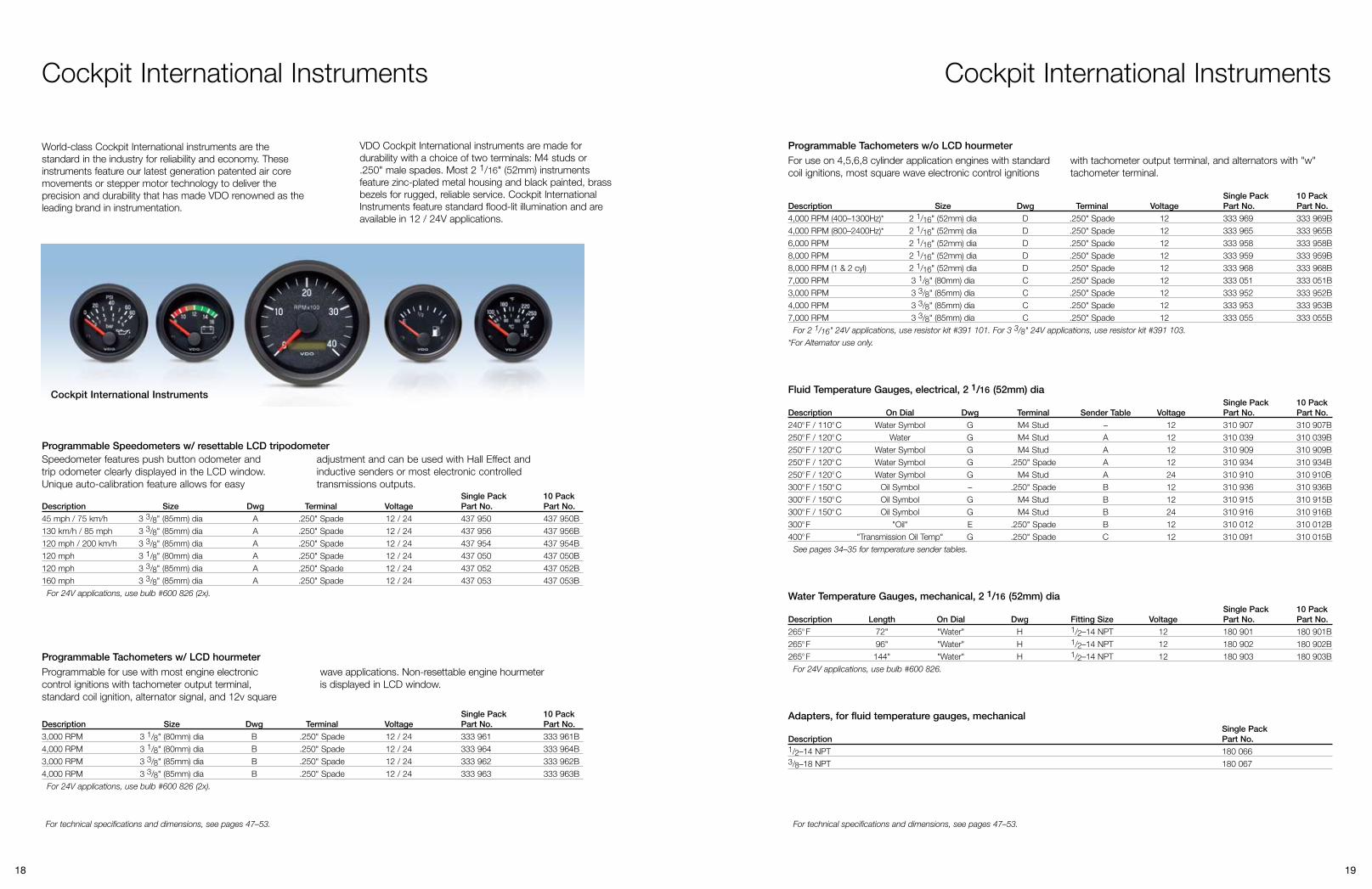
VDO Heavy-Duty Pressure Switches provide an economical and reliable choice for a multitude of pressure switch applications. Available in a variety of part numbers to cover most commonly demanded set points. Optional set points may also be field set to meet customer requirements.
Our Heavy Duty Pressure Switches are compact and compatible with a wide variety of fluids, making them ideal for most engine, brake, hydraulic and air system applications. All switches are provided with an insulated ground terminal to assure a quality ground circuit.
Normally Open–single circuit; 2 terminals, insulated ground Single Pack 10 Pack Range Part No. Part No.
4 PSI 230 404 230 404B15 PSI 230 415 230 415B60 PSI 230 460 230 460B
Normally Closed–single circuit; 2 terminals, insulated ground Single Pack 10 Pack Range Part No. Part No.
4 PSI 230 504 230 504B15 PSI 230 515 230 515B60 PSI 230 560 230 560B
Dual Circuit–normally open, normally closed, insulated ground Single Pack 10 Pack Range Part No. Part No.
4 PSI 230 604 230 604B15 PSI 230 615 230 615B60 PSI 230 660 230 660B
Overall dimensions: 2.52" (64mm) L X 1.47" (37mm) W
Contacts: Silver alloy
Operating Pressure (Set Point Range) 4–24 PSI = 150 PSI 25–90 PSI = 250 PSIProof Pressure: 500 PSIBurst Pressure (Set Point Range) 4–24 PSI = 750 PSI 25–90 PSI = 1,250 PSI
Base: Steel platedDiaphragm: Polyimide film Cover: Glass reinforced polyester
Electrical Ratings Resistive: 15 Amp–6 VDC 8 Amp–12 VDC 4 Amp–24 VDCInductive: 1 Amp–120 VAC 0.5 Amp–240 VAC
Temperature Range: -40o F to 250o F
Terminals: #8–32 screwsThread Size: 1/8–27 NPT
Heavy-Duty Pressure Switch Technical Specifications:
Normally Open: Contacts open until pressure rises which then completes the circuit. Normally Closed: Contacts closed until pressure rises which then breaks the circuit. Direct action blade contact pressure switches with adjustable contact ranges: 4–7 PSI +/- 1; 14–24 PSI +/- 3; 51–90 PSI +/- 7
(2 terminal configuration)
(3 terminal configuration)
Heavy-Duty Pressure Switches
Warning Notice: VDO mechanical oil pressure senders are not to be used with any type of fuel application. VDO mechanical oil pressure senders may be used in motor vehicles and boats only. VDO mechanical oil pressure senders are not suitable for use in aircraft or any other purposes. NO OTHER USE OR APPLICATION IS RECOMMENDED. ANY OTHER USE OR APPLICATION WILL AUTOMATICALLY VOID ANY WARRANTY. VDO AUTOMOTIVE WILL NOT BE RESPONSIBLE FOR THE IMPROPER USE OF THE MECHANICAL OIL PRESSURE SENDERS.
.250”
Illus. A Illus. C Illus. D
Hex nut .187”
Illus. B
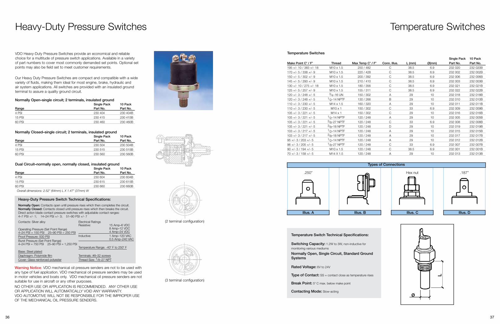
Temperature Switch Technical Specifications:
Switching Capacity: 1.2W to 3W, non-inductive for monitoring various mediums
Normally Open, Single Circuit, Standard Ground Systems
Rated Voltage: 6V to 24V
Type of Contact: SS = contact close as temperature rises
Break Point: 5o C max. below make point
Contacting Mode: Slow-acting
Temperature Switches
Temperature Switches Single Pack 10 Pack
Make Point Co / Fo Thread Max Temp Co / Fo Conn. Illus. L (mm) (mm) Part No. Part No.
195 +/- 10 / 383 +/- 18 M10 x 1.5 250 / 482 C 38.5 6.9 232 020 232 020B170 +/- 5 / 338 +/- 9 M10 x 1.5 220 / 428 C 38.5 6.9 232 002 232 002B150 +/- 5 / 302 +/- 9 M10 x 1.5 200 / 392 C 38.5 6.9 232 006 232 006B145 +/- 5 / 293 +/- 9 M10 x 1.5 210 / 410 C 38.5 6.9 232 003 232 003B130 +/- 10 / 275 +/- 18 M10 x 1.5 180 / 356 C 38.5 6.9 232 021 232 021B125 +/- 5 / 257 +/- 9 M10 x 1.5 155 / 311 C 38.5 6.9 232 022 232 022B120 +/- 3 / 248 +/- 5 3/4 –16 UN 150 / 302 A 29 10 232 018 232 018B120 +/- 3 / 248 +/- 5 1/2 –14 NPTF 130 / 266 B 29 10 232 010 232 010B110 +/- 3 / 230 +/- 5 M14 x 1.5 160 / 320 A 29 10 232 011 232 011B110 +/- 3 / 230 +/- 5 M10 x 1 150 / 302 C 33 6.9 232 009 232 009B105 +/- 3 / 221 +/- 5 M14 x 1 150 / 302 C 29 10 232 016 232 016B105 +/- 3 / 221 +/- 5 1/2 –14 NPTF 120 / 248 A 29 10 232 005 232 005B105 +/- 3 / 221 +/- 5 3/8 –27 NPTF 120 / 248 C 33 6.9 232 008 232 008B105 +/- 3 / 221 +/- 5 3/8 –18 NPTF 120 / 248 D 29 10 232 019 232 019B103 +/- 3 / 217 +/- 5 1/2 –14 NPTF 120 / 248 A 29 10 232 015 232 015B103 +/- 3 / 217 +/- 5 3/8 –18 NPTF 120 / 248 A 29 10 232 017 232 017B95 +/- 3 / 203 +/- 5 1/2 –14 NPTF 120 / 248 A 29 10 232 012 232 012B96 +/- 3 / 205 +/- 5 1/8 –27 NPTF 120 / 248 C 33 6.9 232 007 232 007B90 +/- 3 / 194 +/- 5 M10 x 1.5 120 / 248 C 38.5 6.9 232 001 232 001B70 +/- 3 / 158 +/- 5 M14 X 1.5 120 / 248 A 29 10 232 013 232 013B
Types of Connections

38 39
Table 9: Fuel Level Senders (10–180 Ohm)
Description Type Tank Depth Min (inches)
Tank Depth Max (inches) Voltage Single Pack
Part No.Bulk Pack Part No.
Plated Steel Construction
10–180 Ohm, without low fuel warning contact
Lever Arm 6 23 6–24 226 001 226 001B
10–180 Ohm, without low fuel warning contact, with mounting kit
Lever Arm 6 23 6–24 226 002 226 002B
Composite Construction
10–180 Ohm, with low fuel warning contact
Lever Arm 6 15 3/4 6–24 226 162 226 162B
10–180 Ohm, without low fuel warn-ing contact
Lever Arm 6 15 3/4 6–24 226 168 226 168B
Table 10: Fuel Level Senders (240–33 Ohm)
Description Type Tank Depth Min (inches)
Tank Depth Max (inches) Voltage Single Pack
Part No.Bulk Pack Part No.
Plated Steel Construction
240–33 Ohm, without low fuel warning contact
Lever Arm 6 23 6–24 226 007 –
Composite Construction
240-33 Ohm, with low fuel warning contact
Lever Arm 6 15 3/4 6–24 226 163 226 163B
240-33 Ohm, without low fuel warning contact
Lever Arm 6 15 3/4 6–24 226 169 226 169B
Table 11:Fuel Level Senders (0–90 Ohm)
Description Type Tank Depth Min (inches)
Tank Depth Max (inches) Voltage Single Pack
Part No.Bulk Pack Part No.
Plated Steel Construction
0–90 Ohm, without low fuel warning contact
Lever Arm 6 23 6–24 226 008 –
Composite Construction
0–90 Ohm, with low fuel warning contact
Lever Arm 6 15 3/4 6–24 226 164 226 164B
0–90 Ohm, without low fuel warning contact
Lever Arm 6 15 3/4 6–24 226 170 226 170B
Fuel and Water Level Senders
Plated Steel Construction Sender
Composite Construction Sender
Tubular Sender
Plated Steel ConstructionDesigned for severe duty use, each of these senders contains an SAE standard five hole metal mounting flange and body components which can be adjusted from 6" to 23" tank depth. Adaptable to right hand or left had swing arm. Each contains thick film resistor technology for greater resistance to wear associated with standard wire wound units. Each kit contains neoprene mounting gasket and mounting screws.
For tanks without flange mounting holes our optional tank mounting kit may be used.Composite ConstructionOur newest and most economical line of adjustable senders contain SAE standard five hole configuration and thick film resistor technology. These senders also are available with low fuel warning contact. Sender mounting gasket and hardware is included when bought in single pack version only.
Table 13: Fresh Water Level Senders
Description Type Tank Depth Min (inches)
Tank Depth Max (inches) Voltage Single Pack
Part No.10 Pack Part No.
10–180 Ohm, without warning contact, Stainless Steel
Lever 8 24 6–24 226 452 226 452B
Fuel and Water Level Senders
Length (inches)
Length (mm) Reference No. Single Pack
Part NoBulk Pack Part No.
9.90 251.5 82/6/97 224 062 224 062B
11.00 279.5 82/7/22 224 055 224 055B
12.22 310.5 82/5/136 224 063 224 063B
14.6 372 82/7/4 224 065 224 065B
15.93 404.5 82/5/142 224 054 224 054B
17.07 433.5 82/5/98 224 066 224 066B
19.63 498.5 82/5/117 224 067 224 067B
21.32 541.5 82/7/58 224 003 224 003B
23.48 596.5 82/7/17 224 069 224 069B
27.22 691.5 82/5/11 224 004 224 004B
31.00 787.5 82/5/72 224 049 224 049B
32.9 835 82/5/34 224 051 224 051B
5.9 150 224-011-000-015X 224 215 224 215B
6.3 160 224-011-000-016X 224 216 224 216B
6.7 170 224-011-000-017X 224 217 224 217B
7.1 180 224-011-000-018X 224 218 224 218B
7.5 190 224-011-000-019X 224 219 224 219B
7.9 200 224-011-000-020X 224 220 224 220B
8.3 210 224-011-000-021X 224 221 224 221B
8.7 220 224-011-000-022X 224 222 224 222B
9.1 230 224-011-000-023X 224 223 224 223B
9.4 240 224-011-000-024X 224 224 224 224B
9.8 250 224-011-000-025X 224 225 224 225B
Table 12: Fuel Level Senders (90–0 Ohms)
Constructed of durable stainless steel, these adjustable senders are oil filled and designed for fresh water
Our tube senders contain an SAE standard five hole metal flange. These senders are ideal in applications where vehicle or equipment movement causes severe fuel sloshing and premature sender failure is a problem. The float, attached to resistive wires, is captive within the tube which limits exposure to fuel slosh thereby substantially increasing
applications. Complete mounting kit is supplied with each sender.
sender life. These senders are well suited for instances where tank dimensions do not allow for swing arm type senders. Each sender is supplied with a neoprene mounting gasket. For tanks without flange mounting holes, our optional tank mounting kit may be used.
Length (inches)
Length (mm) Reference No. Single Pack
Part NoBulk Pack Part No.
10.2 260 224-011-000-026X 224 226 224 226B
10.6 270 224-011-000-027X 224 227 224 227B
11.0 280 224-011-000-028X 224 228 224 228B
11.4 290 224-011-000-029X 224 229 224 229B
11.8 300 224-011-000-030X 224 230 224 230B
12.2 310 224-011-000-031X 224 231 224 231B
12.6 320 224-011-000-032X 224 232 224 232B
13.0 330 224-011-000-033X 224 233 224 233B
13.4 340 224-011-000-034X 224 234 224 234B
13.8 350 224-011-000-035X 224 235 224 235B
14.2 360 224-011-000-036X 224 236 224 236B
14.6 370 224-011-000-037X 224 237 224 237B
15.0 380 224-011-000-038X 224 238 224 238B
15.4 390 224-011-000-039X 224 239 224 239B
15.7 400 224-011-000-040X 224 240 224 240B
17.7 450 224-011-000-045X 224 245 224 245B
19.7 500 224-011-000-050X 224 250 224 250B
21.7 550 224-011-000-055X 224 255 224 255B
23.6 600 224-011-000-060X 224 260 224 260B
25.6 650 224-011-000-065X 224 265 224 265B
27.6 700 224-011-000-070X 224 270 224 270B
29.5 750 224-011-000-075X 224 275 224 275B
31.5 800 224-011-000-080X 224 280 224 280B
Bulk pack fuel senders do not include mounting gasket. Composite construction fuel senders must be installed using mounting kit 600 408.

40 41
340 020
340 001
340 060
Generator SendersFor use with VDO speedometers and tachometers designated as generator-type (4 pulses per revolution).
Senders w/o odometer revolution counter terminal (2 terminals)Description Part No.7/8–18 thread 340 001M22 x 1.5 thread 340 002
Senders w/ odometer revolution counter terminal (3 terminals)Description Part No.7/8–18 thread 340 008M22 x 1.5 thread 340 007
Drive Keys for generator senders listed aboveDescription Part No.
.152"–tang 340 060
.187"–tang 340 061
.203"–tang 340 062
.104"–square 340 065
Inductive / Magnetic Pick-Up SendersFor inductive and programmable speedometers and tachometers.Description Part No.
2" (51mm) long, 3/4–16 thread 340 020
Hall-Effect SendersFor electronic, programmable speedometers, 7/8–18 thread, 16 pulse.Description Part No.
Standard, GM 340 011GM, through-drive, for cruise control hook-up 340 012Ford, plug-in 340 013Ford, plug-in, through-drive 340 014
Speedometer and Tachometer Senders
340 011
340 013
Nylon Tubing Kits Copper Tubing Kits
Universal Bushing Kit
T-Adapters
Safety Mount Brackets
Tubing KitsDescription Fitting Size Part No.
0–150 PSI nylon tubing (6') 1/8–27 and 1/4–18 NPT adapters 150 8510–150 PSI nylon tubing (16') 1/8–27 and 1/4–18 NPT adapters 150 8550–400 PSI copper tubing (6') 1/8–27 and 1/4–18 NPT adapters 150 856
Warning Notice: Tubing Kits are not for use on any aircraft, fuel, or brake applications (vacuum, hydraulic or air).
Universal Bushing KitsInside diameter 1/8–27 NPT, for use with all pressure and temperature senders.Description Part No.
Includes 1/4–18, 3/8–18, and 1/2–14 bushings 240 903Includes M16 x 1.5, M14 x 1.5, M12 x 1.0, M10 x 1.0, 1/8 x 28 BSP 240 904D
Adapters and FittingsDescription Part No.
Male 1/8–27 NPT 240 855Male M10 x 1 240 850Weld-on Adaptor for Pyrometer Sender 240 8631/8 male to 1/8 female Angled Brass Adaptor 240 828Adaptor M10 Right Angle Oil Pressure Adaptor 240 041Remote Hose ADP Kit M10 x 1 150 752
Anti-Glare RingsDescription Part No.
2 pk. for 52mm gauge 240 005
Safety Mount Brackets for 2 1/16" (52mm) dia instruments. Made of a flexible, rubber material for cockpit safety. Matte black.Description Dimensions (H x D x L) Part No.
1 opening 3 7/8" x 1 1/4" x 2 1/2" (98 mm x 32 mm x 64 mm) 240 8022 openings 3 7/8" x 1 1/4" x 4 7/8" (98 mm x 32 mm x 124 mm) 240 8033 openings 3 7/8" x 1 1/4" x 7 1/2" (98 mm x 32 mm x 191 mm) 240 804
Mounting CupsSteel mounting cups with smooth black or chrome finishes.
Chrome Black Description Part No. Part No.
For 2 1/16" (52mm) dia gauge 240 017* 240 016*For 3 3/8" (85mm) dia gauge 240 019 240 018
Will not work with 2 1/16" (52mm) dia clocks, tachometers, outside temp. gauges or pyrometers.
Instrument Accessories and Service Parts
Anti-glare Rings
Mounting Cups

42 43
Adjustable Mounting Cups
Mounting Brackets
Instrument Accessories and Service Parts
Instrument Panel Hole Cover
Adjustable Mounting CupsIn durable ABS plastic with matte black finish. Description Part No.
2 1/16" (55mm) dia, long version for outside temp. gauge, pyrometer, clock, ammeter and 2 1/16" (55mm) dia tach. 240 101
Mounting Brackets for 2 1/16" (52mm) dia instrumentsVDO mounting brackets are metal with smooth black or chrome finishes. 1, 2, and 3 opening units.
Chrome Black Description Dimensions (H x D) Part No. Part No.
1 opening 2 7/8" x 2 11/16" (73mm x 68mm) 240 034 240 0272 openings 2 7/8" x 5 3/16" (73mm x 132mm) 240 035 240 0283 openings 2 7/8" x 7 1/2" (73mm x 205mm) 240 036 240 029
Instrument Panel Hole Covers Single Pack 10 Pack Description Part No. Part No.
2 1/16" (52mm) dia 240 864 240 864B3 3/8" (85mm) dia 240 866 240 866B
Reducing RingsVDO’s matte black mounting rings permit the installation of smaller units in larger existing dashboard openings. Description Part No.
From 2 3/8" to 2 1/16" (60mm x 52mm) 600 851From 3 3/8" to 3 1/8" (86mm x 79mm) 600 885
Position Indicator SendersFor use with VDO 12 / 24V gauges.Description Part No.
Single station transmitter, for operating one VDO indicator 440 003Dual station transmitter, for operating two VDO indicators from one sender 440 004Installation kit and arm assembly 440 050Replacement arm 440 100
240 026
440 003
Acoustical Warning Alarm
Instrument Accessories and Service Parts
Acoustical Warning Alarm, 2 1/16" (52mm) dia Single Pack Bulk Pack Description Terminal Voltage Part No. Part No.
Piezo Buzzer .250" Spade 12 / 24 4071101 03 230 702
Analog Instrument Wiring Harnesses and AccessoriesDescription Part No.
6 Instrument Wire Harness w/ insulated connectors for VDO Instruments 240 022Pyrometer Extension Cable (30 ft.) 240 0926 Pin Tach/Speedo Connector with terminal end 240 0538 Pin connector for Speedometer/Tachometer with hourmeter 240 0248 Pin connector for Speedometer/Tachometer with hourmeter / 100 pk 240 024B100 pk .25" Blade Terminals 240 045Ammeter Wire Kit 240 021Universal 1 Instrument Wire Kit 240 0233-Prong Instrument connector w/ terminals for Severe Duty 240 0263-Prong Instrument connector w/o terminals for Severe Duty 600 8143-Prong Instrument connector w/o terminals for Severe Duty / 100 pk 600 814B3-Prong Instrument connector w/ terminals for Vision & Cockpit Int'l 240 0253-Prong Instrument connector w/o terminals for Vision & Cockpit Int'l / 100pk 240 025BReplacement Cylinder Head Temp gauge lead wire, 15' 240 701
CANcockpit HarnessesDescription Part No.
Harness Type A (Master) A2C53041729Harness Type B (Master to Satellite) A2C53171895Harness Type C (Satellite to Satellite) A2C53041730
CANcockpit Harness ComponentsDescription Part No.
Pin Housing for 26 Pin Connector X11-602-000-001Coupling for Pin Housing (26 Pin Connector) X11-602-000-002Pin for 26 Pin Connector (Master) X11-602-000-003Pin Locking for 26 Pin Housing (Master) X11-602-000-004Bracket for Coupling 26 Pin Housing (Master) X11-602-000-0054 pin connector for master X11-602-000-006Pin for 4+6 pin connector X11-602-000-0076 pin connector for satellite X11-602-000-008
240 022

44 45
600 402
Black Square Bezels
600 601
Spin-LokTM Mounting Rings
Instrument Accessories and Service Parts
Stud Mounting KitsFor converting Spin-LokTM mounted instruments to stud type mounting.Gauge Diameter Part No.
2 1/16" (52mm) 600 4023 1/8" (80mm), 3 3/8" (85mm) 600 401
Severe Duty Flush Mounting KitsTo flush mount Severe Duty Instruments from behind an instrument panel. Kit works with Severe Duty instruments only.Description Part No.
Severe Duty flush mount kit, 3 3/8" (85mm) 600 409Severe Duty flush mount kit, 2 1/16" (52mm) 600 410
Replacement Spin-LokTM Mounting RingsGauge Diameter Part No.
2 1/16" (52mm) 600 4043 1/8" (80mm) 600 4053 3/8" (85mm) 600 406
Optional Black Square Bezels (Severe Duty only)Description Part No.
For 2 1/16" (52mm) 600 001For 3 3/8" (85mm) 600 002
Fuel Sender Service PartsDescription Part No.Replacement float for lever arm type sender 600 601Replacement neoprene gasket for fuel and water senders 226 053SAE 5 hole mounting flange kit 226 451Composite fuel sender mounting kit 600 408
Type A (fits sockets #600 813, #600 816 and #600 817)Description Part No.9/32" (7mm), 12V, 2W 600 8029/32" (7mm), 24V, 3W 600 807
Type B: (fits sockets #600 818 and #600 819)Description Part No.11/32" (9mm), 12V, 2W 600 80411/32" (9mm), 12V, 4W 600 806
Type C: (fits socket #600 821)Description Part No.3/8" (10mm), 12V, 2W 600 820
Type D (peanut type, fits socket #600 823)Description Part No.Peanut bulb, 12V, 1.2W 600 809Peanut bulb, 24V, 1.2W 600 829Peanut bulb, 12V, 1.2W, red 600 830Peanut bulb, 24V, 1.2W, red 600 822
Type E: (fits socket #600 840)Description Part No.Wedge-base bulb, 12V 600 815Wedge-base bulb, 24V 600 826
Insulated Light Bulb SocketsDescription Part No.3/8" (10mm), uses bulb type A 600 81315/32" (12mm), uses bulb type B 600 819Uses wedge-type bulb E 600 840Uses peanut-type bulb D 600 823Illumination bulb holder, 3 3/8" (10mm), Severe Duty only 600 841Illumination bulb holder, 2 1/16" (52mm), Severe Duty only 600 842Severe Duty warning light bulb and socket, 12V 600 834Severe Duty warning light bulb and socket, 24V 600 835
All bulbs sold in packages of four.
A
600 813 600 819
600 823 600 840
B
D
E
C
Light Bulbs and Sockets

46 47
Light Diffusers
Warning Lights
Light Bulbs and Sockets
Light Bulb SocketsDescription Part No.3/8" (10mm) steel, uses bulb type A 600 8163/8" (10mm) brass, uses bulb type A 600 8175/8" (16mm) steel, uses bulb type C 600 82115/32" (12mm) steel, uses bulb type B 600 818
Panel Mount Warning Lights12V snap-in warning lights with bulb. Requires 11/32" hole.Description Part No.Red lens 600 844Green lens 600 845Yellow lens 600 846Blue lens 600 847
Light Diffusers The easy and convenient way to change the lighting color in your gauge. Diffuser simply slips over the existing light bulb. Sold in packages of four.Description Part No.Red, Type A, 9/32" bulb 600 853Green, Type A, 9/32" bulb 600 856Red, Type B, 11/32" bulb 600 857Green, Type B, 11/32" bulb 600 858Red, Type D, “peanut” bulb 600 859Green, Type D, “peanut” bulb 600 860Red, Types E and C bulbs 600 861Green, Types E and C bulbs 600 862Blue, Types E and C bulbs 600 863Amber, Types E and C bulbs 600 864
Optional In-Gauge Warning Lights (Severe Duty only)Description Terminal Voltage Part No.
For volt, temp, pressure and fuel .250" Spade 12 05 800 762For volt, temp, pressure and fuel .125" Spade 24 05 800 764
600 816 600 817
600 821 600 818
Technical Specifications and Dimensions
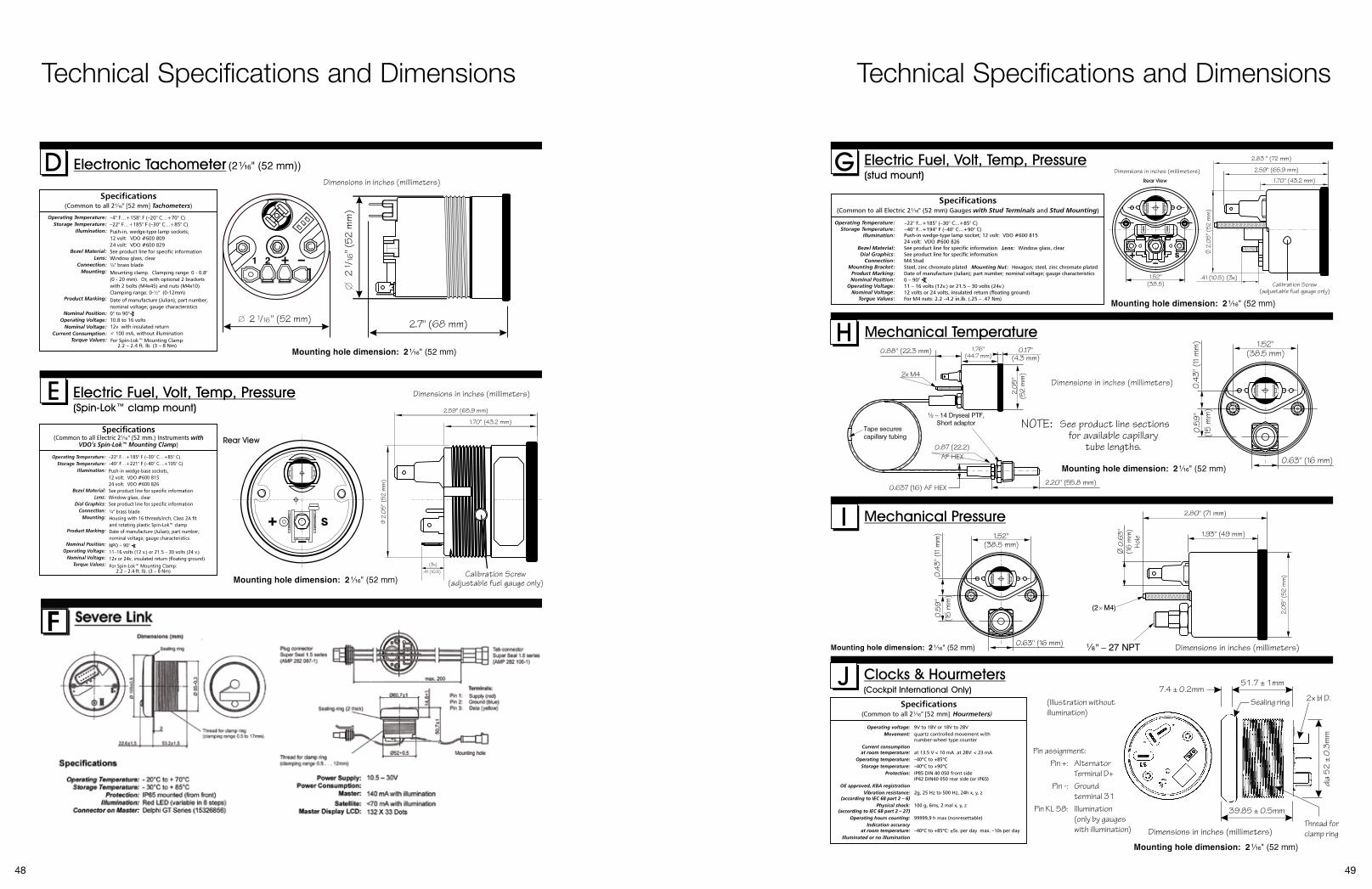
48 49
Technical Specifications and Dimensions Technical Specifications and Dimensions
Operating voltage: 9V to 18V or 18V to 28V Movement: quartz controlled movement with number-wheel type counter Current consumption at room temperature: at 13.5 V < 10 mA at 28V: < 23 mA Operating temperature: –40ºC to +85ºC Storage temperature: –40ºC to +90ºC Protection: IP85 DIN 40 050 front side IP42 DIN40 050 rear side (or IP65) OE approved, KBA registration Vibration resistance: 2g, 25 Hz to 500 Hz, 24h x, y, z (according to IEC 68 part 2 – 6) Physical shock: 100 g, 6ms, 2 mal x, y, z (according to IEC 68 part 2 – 27) Operating hours counting: 99999,9 h max (nonresettable) Indication accuracy at room temperature: –40ºC to +85ºC: ±5s. per day max. –10s per day Illuminated or no illumination
(Illustration without illumination)
Sealing ring
Pin assignment: Pin +: Alternator Terminal D+ Pin -: Ground terminal 31 Pin KL 58: Illumination (only by gauges with illumination)
39.85 ± 0.5mm
51.7 ± 1mm
2x bl D.
Thread forclamp ring
7.4 ± 0.2mm
dia
52
± 0
.3m
m
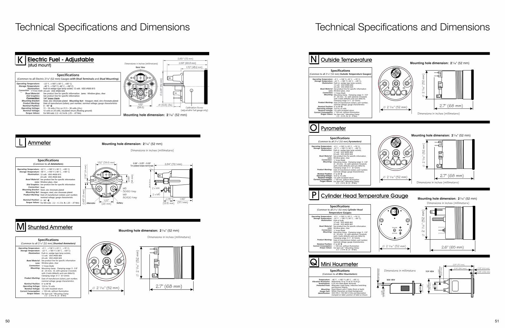
50 51
Technical Specifications and Dimensions Technical Specifications and Dimensions

52 53
Technical Specifications and Dimensions Technical Specifications and Dimensions

54 55
Cross ReferenceCatalog Part No. Component Part No.VISION CHROME150 192 151-07-01-91150 1921 151-07-01-91150 1922 151-07-01-91437 191 A2C59519249150 191 151-07-01-88150 1911 151-07-01-88150 1912 151-07-01-88150 194 151-07-01-89150 1941 151-07-01-89150 1942 151-07-01-89150 197 151-07-01-90150 1971 151-07-01-90150 1972 151-07-01-90150 291 151-07-01-91150 2911 151-07-01-91150 2912 151-07-01-91180 191 181-01-13-83180 192 181-01-13-84301 194 A2C60001326301 194 A2C60001326301 195 A2C60001327301 197 A2C60001328310 191 N02-340-414310 193 N02-340-414310 194 A2C60001301310 195 A2C60001302310 1951 A2C60001302310 1952 A2C60001302310 196 A2C60001303310 1961 A2C60001303310 1962 A2C60001303332 191 A2C60000777332 191 A2C60000777332 193 A2C60001376333 192 N02-064-249333 192 N02-064-249333 193 N02-064-251333 194 N02-064-253333 197 N02-062-343333 199 N02-062-341350 194 A2C60001351350 1941 A2C60001351350 1942 A2C60001351350 195 A2C60001352350 196 A2C60001353350 1961 A2C60001353350 1962 A2C60001353350 197 A2C60001354350 198 A2C60001355350 1981 A2C60001355350 1982 A2C60001355350 199 A2C60001356VISION BLACK150 102 150-015-001K150 1041 150-077-003C150 1042 150-077-003C190 103 190-077-001K310 108 310-010-002K310 109 310-010-003K333 154 N02-062-234350 101 350-010-008K350 102 350-010-007K370 155 V1261001331C397 155 397-015-001K437 151 N01-112-254437 154 437-015-001K437 156 437-015-007G437 157 437-015-016C437 158 437-015-017C
Catalog Part No. Component Part No.
437 160 N01-111-214150 101 150-077-007C150 103 150-077-008C150 104 150-077-003C150 105 151-07-01-21150 107 150-077-002C150 121 150-077-004C150 131 150-077-005C180 101 180-077-001C180 105 180-077-005C190 104 190-077-004C190 105 190-077-005C301 104 301-010-003C301 105 301-010-004C301 106 301-010-006C301 107 301-010-005C310 104 310-010-005C310 105 310-010-006C310 106 310-010-007C310 107 310-010-008C310 111 310-010-022C310 151 81-072-045310 153 310-015-002C310-010-002K 310-010-002K310-010-003K 310-010-003K332 103 332-010-002C332 903 A2C60000776333 151 N02-062-275333 152 N02-062-238333 155 N02-062-232333 156 333-015-027C333 158 333-015-018C333 159 81-072-045333 160 333-015-022C333 162 N02-064-233333 163 N02-064-231333 164 N02-064-229350 104 350-010-004C350 105 350-010-013C350 106 350-010-003C350 106 350-010-003C350 107 350-010-012C350 108 350-010-002C350 109 350-010-011C350 110 350-010-001C350 111 350-200-001C350 112 350-200-002C350 112 350-200-002C397 154 N02-300-706397-015-001K 397-015-001K437 152 N01-112-252437 152 N01-112-251437 153 N01-112-250437 153 N01-112-249437 155 N01-112-416437 155 N01-112-415SEVERE DUTY BLACK & SEVERE DUTY CHROME1901101 N02-420-7151901103 N02-420-7111904101 N02-420-7151904102 N02-420-7173011101 N02-222-1253011102 N02-222-6073011103 N02-222-1293011104 N02-222-6113011105 N02-222-1333011106 N02-222-6153011109 N02-230-7253011121 N02-230-8253011121 N02-230-825
Catalog Part No. Component Part No.
3011154 N02-222-6133014101 N02-222-1253014102 N02-222-6073014103 N02-222-1293014104 N02-222-6113014105 N02-222-1333014106 N02-222-6153014109 N02-230-7253014121 N02-230-8253101103 N02-321-6573101106 N02-340-7193101107 N02-321-6613101108 N02-321-6653101109 N02-321-7453101154 N02-321-7433104101 N02-321-6533104102 N02-321-7373104103 N02-321-6573104104 N02-321-7413104106 N02-340-7193104107 N02-321-6613104108 N02-321-6653104109 N02-321-7453321101 N02-410-8273321101 N02-410-8273321102 N02-410-9253321102 N02-410-9253324101 N02-410-8273324102 N02-410-9253331101 N02-012-4473331102 N02-012-4513331105 N02-012-2293331106 N02-012-2333331107 N02-012-1253331108 N02-012-4253334101 N02-012-4473334102 N02-012-4513334103 N02-012-7413334105 N02-012-2293334106 N02-012-2333501103 N02-124-1953501104 N02-124-5853501105 N02-124-1993501106 N02-124-5893501109 N02-124-2073501110 N02-124-5973501121 N02-124-1213501122 N02-124-5213501123 N02-124-1253504101 N02-124-1913504102 N02-124-5813504103 N02-124-1953504104 N02-124-5853504105 N02-124-1993504106 N02-124-5893504107 N02-124-2033504108 N02-124-5933504109 N02-124-2073504110 N02-124-5973701101 N03-270-6133704101 N03-270-6133821106 N03-211-4114071101 N03-230-7014071101 N03-230-70102 012 126 N02-012-12502 012 150 N02-012-14902 012 426 N02-012-42502 012 430 N02-012-42902 124 122 N02-124-12102 124 126 N02-124-125
Catalog Part No. Component Part No.
02 124 166 N02-124-16502 124 168 N02-124-16702 124 522 N02-124-52102 124 566 N02-124-56502 124 568 N02-124-56702 222 106 N02-222-10502 222 112 N02-222-11102 222 306 N02-222-30502 222 312 N02-222-31102 222 512 N02-222-51102 222 712 N02-222-71102 230 712 N02-230-71102 230 812 N02-230-81102 321 628 N02-321-62702 321 728 N02-321-72702 400 310 N02-420-71102 410 806 N02-410-80502 410 906 N02-410-90502 420 712 N02-420-71103 200 514 N03-211-41103 230 702 N03-230-70103 270 612 N03-270-611COCKPIT INTERNATIONAL150 030 151-07-01-54150 042 151-20-03-09150 051 151-07-01-36150 052 151-07-01-53150 904 150-037-013C150 905 150-037-014C150 906 150-037-016C150 921 150-037-011C151 002 151-12-1R151 910 V1122015064C180 901 180-037-011C180 902 180-037-012C180 903 180-037-013C190 903 190-037-004C190 904 190-037-005C190 963 190-035-003C190 966 190-035-003C301 015 301-220-001C301 030 301-220-004C301 901 301-030-005C301 902 301-040-005C301 903 301-030-004C301 904 301-040-004C301 905 301-030-003C301 906 301-040-003C301 930 301-030-008C310 012 310-220-002C310 033 V1231003026C310 033 V1231003026C310 039 310-220-003C310 901 V1231003026C310 907 310-030-009C310 909 310-030-006C310 910 310-040-006C310 911 310-030-010C310 915 310-030-007C310 916 310-040-007C310 934 350-030-021C310 936 310-030-024C310 951 310-035-002C310 951 310-035-002C310 953 310-035-002C323 892 V1531007177A331 953 331-810-012-001C331 955 331-810-012-003C331 957 331-810-012-004C331 959 331-810-012-002C331 960 331-810-012-007C
Cross ReferenceCatalog Part No. Component Part No.
331 960 331-810-012-007332 041 332-220-001C332 901 332-030-002C332 902 332-040-002C332 932 332-030-001C333 051 N02-062-258333 055 N02-062-256333 952 N02-062-269333 953 N02-062-267333 958 333-035-019C333 959 333-035-020C333 961 333-035-010C333 962 N02-064-245333 963 N02-064-243333 964 333-035-011C333 965 333-035-021C333 968 333-015-041C333 969 333-035-029C350 040 350-220-002C350 041 350-220-001C350 290 A2C60001357350 901 350-030-007C350 902 350-040-007C350 909 350-030-009C350 910 350-040-009C350 913 350-030-010C350 934 350-030-021C437 050 N01-112-248437 052 N01-112-262437 053 N01-112-220437 950 N01-112-243437 954 N01-111-215437 956 N01-112-231SERIES 1120 302 124-11-18-09150 301 151-20-03-03150 306 151-07-01-67150 307 151-07-01-25150 330 151-07-01-24150 361 V1121020027C180 301 181-01-13-16180 302 V1131020392C180 308 181-01-13-44180 310 181-01-13-18180 315 181-01-13-19180 317 181-01-13-50190 301 191-03-04-05301 301 301-260-003C301 302 301-260-002C310 303 310-260-001C310 304 310-260-002C332 341 332-260-001C332 342 332-260-002C333 353 N02-062-240333 355 N02-062-271333 363 N02-064-247350 303 350-260-001C350 306 350-260-002C437 353 N01-112-215437 354 N01-112-223HOURMETERS331 534 V1763003213A331 536 V1763018054331 537 V1763018040331 537 V1763018040331 539 V1763018047331 539 V1763018047331 953 331-810-012-001C331 955 331-810-012-003C331 958 V1763018061331 958 V1763018061
Catalog Part No. Component Part No.
CANCOCKPITA2C53171895 A2C53171895A2C60000011 A2C60000011 A2C60000012 A2C60000012 A2C60000013 A2C60000013 A2C60000016 A2C60000016 A2C60000018 A2C60000018 A2C60000061 A2C60000061 A2C60000062 A2C60000062 A2C60000066 A2C60000066 A2C60000067 A2C60000067 A2C60000068 A2C60000068 A2C60000069 A2C60000069 A2C60000111 A2C60000111 A2C60000112 A2C60000112 A2C60000116 A2C60000116 A2C60000117 A2C60000117 A2C60000119 A2C60000119 A2C60000305 A2C60000305 A2C60000306 A2C60000306 A2C60000308 A2C60000308 A2C60000311 A2C60000311 A2C60000312 A2C60000312 A2C60000315 A2C60000315 A2C60000319 A2C60000319 A2C60000320 A2C60000320 A2C60000321 A2C60000321 A2C60000322 A2C60000322 A2C60000323 A2C60000323 A2C60000324 A2C60000324 A2C60000325 A2C60000325 A2C60000327 A2C60000327 A2C60000328 A2C60000328 A2C60000329 A2C60000329 A2C60000331 A2C60000331 A2C60000333 A2C60000333 A2C60000334 A2C60000334 A2C60000335 A2C60000335 A2C60001885 A2C60001885 A2C60001892 A2C60001892 A2C60005001 A2C60005001 CAN SEVERE LINKA2C53092432 A2C53092432A2C59500012 N02-012-933N02-012-920 N02-012-919N02-012-922 N02-012-921N02-140-512 N02-140-511N02-140-516 N02-140-515N02-224-080 N02-224-079N02-311-542 N02-311-541N02-311-546 N02-311-545N02-311-552 N02-311-551N02-413-058 N02-413-057N02-413-066 N02-413-065SENSOR / SENDERS440 003 N03-220-430 440 004 N03-220-438

Continental Commercial Vehicles & Aftermarket 6755 Snowdrift Road Allentown, PA 18106 USA Tel: (610) 289-0488 Fax: (610) 289-1766 E-mail: [email protected] www.vdo.com VDO - A trademark of the Continental Corporation
Customer Service Tel: (800) 564-5066 or (610) 366-8489 Fax: (800) 752-7224 or (610) 366-9837
Technical Support Tel: (800) 265-1818 or (610) 289-1390 Email: [email protected]
We reserve the right to make changes in availability as well as technical changes without prior notice.
Not intended for aircraft applications.
Part #VSOC0908 (Supersedes Part#SVSOC0907) | English © 2008Continental CorporationPrinted in the USA