
2009-2011PrecedentGolfCar Owner’sManual
72
2009-2011 Precedent Golf Car Owner’s Manual Electric and Gasoline
Transcript of 2009-2011PrecedentGolfCar Owner’sManual

2009-2011 Precedent Golf CarOwner’s Manual
Electric and Gasoline


NOTICE
Warranty information appears at the end of this manual. No other warranties, expressed or implied, are contained herein.Your authorized representative checked the vehicle before it was delivered to you and will provide you a copy of thecompleted vehicle warranty registration form.
Club Car is not liable for errors in this manual or for incidental or consequential damages that result from the use ofthe material in this manual.
The two-passenger golf vehicle conforms to the current American National Standards Institute’s Z130 Safety andPerformance Requirements for Golf Cars. This standard, which promotes safety in the design, application, and operationof golf cars, defines a golf car as “a vehicle used to convey a person or persons and equipment to play the game of golf inan area designated as a golf course.” Throughout this manual, the words “golf car” and “vehicle” are used interchangeably.
This manual contains proprietary information that is protected by copyright. All rights are reserved. No part of this manualmay be photocopied, reproduced, or translated to another language without the written consent of Club Car, LLC.
The information contained in this document is subject to change without notice.
Club Car reserves the right to make design changes to vehicles without obligation to make these changes on unitspreviously sold.
These vehicles do not conform to Federal Motor Vehicle Safety Standards for automobiles or to FMVSS 500 for low-speedvehicles, and are not equipped for operation on public streets, roads, or highways.
If in English, this manual is the Original Instructions provided by the manufacturer. If in any language other than English,this manual is a translation of the Original Instructions.
P.O. Box 204658Augusta, Georgia 30917–4658 USA
Telephone 706–863–3000Service Parts Fax 706–855–7413
www.clubcar.com
Copyright © 2008, 2009, 2010, 2011 Club Car, LLCClub Car, Tranquility, and ArmorFlexare registered trademarks of Club Car, LLCThis manual effective August 1, 2008
2009-2011 Precedent Golf Car Owner’s Manual Page 1

FOREWORD
Thank you for choosing Club Car, the name most widely recognized as the industry leader in vehicle efficiencyand long-lasting value. You have chosen the finest golf car on the market. Please protect your investment andensure that your Club Car provides years of reliable, superior performance by reading and following the maintenanceinstructions in this manual.Your comfort and safety are important to us as well, so we urge you to read and follow the step-by-step operatinginstructions and safety precautions in this manual. These instructions must be followed in order to avoid the risk ofsevere personal injury. If you rent or loan your vehicle to others, we recommend that you ask them to read this manualbefore they operate the vehicle.Club Car products are backed by a customer support system designed to offer you fast, courteous service. In the eventthat your golf car needs repairs or service, please contact your local authorized Club Car dealer or distributor, who willbe able to provide technical advice, perform warranty work, and sell parts and service manuals. For the name andaddress of the authorized Club Car dealer or distributor nearest you, logon to our web site at www.clubcar.com orcall 1-800-ClubCar (258-2227). If you would prefer to write to us, direct your letter to: Club Car, Attention: MarketingServices, P.O. Box 204658, Augusta, Georgia 30917-4658 USA.We hope you will consider this owner’s manual a permanent part of your golf car. If you sell the vehicle, please includethe manual so that the next owner will have the important operating, safety, and maintenance information it contains.
REGULAR MAINTENANCE ITEMS PERIODIC MAINTENANCE ITEMS
Engine Oil Filter (286 cc and 351 cc)
CC P/N 1016467
Spark Plug O.H.V. (286 cc and 351 cc)
Either CC P/N AM1232301 or 101881101
Engine Air Filter (286 cc and 351 cc)
CC P/N 102558201
Spring Tune-Up Kit
CC P/N AM1262501
Engine Fuel Filter (286 cc and 351cc)
CC P/N 102003201
Fuse, 10 Amp, Starting Circuit (gasoline vehicle)
Fuse under Seat near Solenoid
CC P/N 1012295
Battery Terminal Protector Spray
CC P/N 1014305
Fuse, 15 Amp, Tow/Run Switch (electric vehicle)
Fuse under Seat beneath Electronics Module Cover
CC P/N 102538601
Dry Moly Lube
CC P/N 1012151
Fuse, 10 Amp, Headlight Circuit (if equipped)
Fuse under Seat beneath Electronics Module Cover
CC P/N 1012295
Fuse, 0.5 Amp, Brake Light Circuit (if equipped)
Fuse under Floormat beneath Floor Cover Plate
CC P/N AM1214301
Page 2 2009-2011 Precedent Golf Car Owner’s Manual

TABLE OF CONTENTS
Safety Decal and Feature Identification .................................................................................................................. 4
Practice Safety ................................................................................................................................................... 10
Proposition 65 – State of California ...................................................................................................................... 10
Safety Details ......................................................................................................................................................11
General Warnings................................................................................................................................................11
General Information ............................................................................................................................................ 16
Model Identification............................................................................................................................................. 16
Safety Committee ............................................................................................................................................... 16
Controls and Indicators – Electric Vehicles ........................................................................................................... 17
Controls and Indicators – Gasoline Vehicles ......................................................................................................... 22
Pre-Operation and Daily Safety Checklist ............................................................................................................. 26
Driving Instructions ............................................................................................................................................. 28
Towing ............................................................................................................................................................... 30
Transporting on a Trailer ..................................................................................................................................... 31
Storage – Electric Vehicle.................................................................................................................................... 31
Storage – Gasoline Vehicle ................................................................................................................................. 33
Maintenance ...................................................................................................................................................... 34
Periodic Service Schedules ................................................................................................................................. 35
Periodic Lubrication Schedules............................................................................................................................ 40
Batteries – Electric Vehicles ................................................................................................................................ 42
Battery Charger – Electric Vehicles ...................................................................................................................... 46
Single Point Watering System (SPWS)................................................................................................................. 49
Battery – Gasoline Vehicles................................................................................................................................. 51
Engine Oil – Gasoline Vehicles ............................................................................................................................ 52
Fueling Instructions – Gasoline Vehicles .............................................................................................................. 55
Cleaning the Vehicle ........................................................................................................................................... 56
Accessories........................................................................................................................................................ 56
Subsequent Owner Registration .......................................................................................................................... 57
Precedent Four-Passenger Vehicle...................................................................................................................... 57
Vehicle Specifications ........................................................................................................................................ 59
Warranties.......................................................................................................................................................... 61
EC Declaration of Conformity .............................................................................................................................. 65
2009-2011 Precedent Golf Car Owner’s Manual Page 3

Safety Decal and Feature Identification
SAFETY DECAL AND FEATURE IDENTIFICATION
The following pages contain safety decal and feature identification information. For detailed information on specificfeatures, read the appropriate section in this manual.
Page 4 2009-2011 Precedent Golf Car Owner’s Manual

Safety Decal and Feature Identification
ELECTRIC PRECEDENT
2011
9
7
8
6
4
1
3
2 5
1 101825101 Decal, On/Off Key Switch (above key switch) 6 Battery Warning Light
2 102518001 Decal, Operating Instructions (on steering wheel) 7 Accelerator Pedal
3 102519301 Decal, Rollover Warning (on instrument panel) 8 Brake Pedal
4 102555901Decal, Private Speed Notice (below instrumentpanel) (With Private Speed Notice optional)
9 Park Brake Pedal
5 103783001 Decal, Operating Instructions (on steering wheel)
2009-2011 Precedent Golf Car Owner’s Manual Page 5

Safety Decal and Feature Identification
ELECTRIC PRECEDENT
423
1
5
4
6
3
2
78
1 102591901Tag, SPWS Battery Warning (on battery wateringtubes) (with Single-Point Watering System option)
5 103384801 Decal, Tow/Run Warning
2 103238501Decal, Battery Weight Warning (On battery bucket,under seat) (vehicles with 12-volt batteries)
6 Tow/Run Switch
3 103384601 Decal, Water Exposure Caution 7 Forward/Reverse Control
4 103384701 Decal, Battery Terminal Warning 8 Battery Charger Receptacle
Page 6 2009-2011 Precedent Golf Car Owner’s Manual

Safety Decal and Feature Identification
GASOLINE PRECEDENT
2012
2 41
3
5
8 6
7
1 101825101 Decal, On/Off Key Switch (above key switch) 5 Low Oil Warning Light
2 102519201 Decal, Operating Instructions (on steering wheel) 6 Accelerator Pedal
3 102519301 Decal, Rollover Warning (on instrument panel) 7 Brake Pedal
4 103783002 Decal, Operating Instructions (on steering wheel) 8 Park Brake Pedal
2009-2011 Precedent Golf Car Owner’s Manual Page 7

Safety Decal and Feature Identification
GASOLINE PRECEDENT
295
1
1 101960501Decal, Rotating Parts/Hot Manifold Warning (onengine, starter/generator, and transaxle)
4 Choke
2 102517801Decal, Gas/Governor Warning (on fuel tankhold-down bracket)
5 Forward/Reverse Control
3 102517901Decal, Frame Ground Warning (on vehicle frame,under seat)
Page 8 2009-2011 Precedent Golf Car Owner’s Manual
Safety Decal and Feature Identification
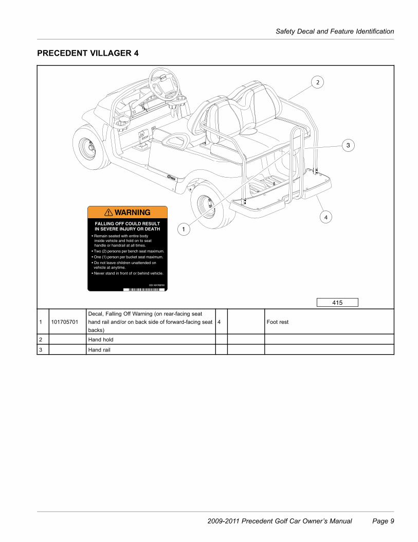
PRECEDENT VILLAGER 4
415
2
1
3
4
2
1 101705701Decal, Falling Off Warning (on rear-facing seathand rail and/or on back side of forward-facing seatbacks)
4 Foot rest
2 Hand hold
3 Hand rail
2009-2011 Precedent Golf Car Owner’s Manual Page 9

Practice Safety
PRACTICE SAFETY
399Figure 1 Practice Safety
Safety signs like you see above may at first seem shocking, but their impact is mild compared with the realityof severe personal injury.Your safety and satisfaction are of the utmost importance to us. That is why before operating the vehicle, we urgeyou to review the information in this manual. Understand and become familiar with the DANGER, WARNING, andCAUTION statements and procedures it contains, along with the safety decals that are affixed to your vehicle.Take time to understand the language of safety. It is a language that can save your life.
PROPOSITION 65 – STATE OF CALIFORNIA
WARNING
• This product contains or emits chemicals or substances that have been determined by the state ofCalifornia to cause cancer and birth defects or other reproductive harm.
Page 10 2009-2011 Precedent Golf Car Owner’s Manual
Safety Details
SAFETY DETAILS
WARNING
• This owner’s manual should be read completely before attempting to drive or service the vehicle.Failure to follow the instructions in this manual could result in property damage, severe personalinjury, or death.
It is important to note that some vital statements throughout this manual and on the decals affixed to the vehicle arepreceded by the words DANGER, WARNING, or CAUTION. For your protection, we recommend that you take specialnotice of these safety precautions. Safety precautions are essential and must be followed.Throughout this manual and on the operation and safety decals affixed to the vehicle, the words “golf car” and“vehicle” are used interchangeably. “Golf car” is defined in the Notice of this manual and no other representation isstated or implied.If any of the operation or safety decals on the vehicle become damaged, have been removed or cannot be easilyread, they should be replaced immediately to avoid possible property damage, personal injury, or death. Contact yourdistributor/dealer.
DANGER
• A DANGER indicates an immediate hazard that will result in severe personal injury or death.
WARNING
• A WARNING indicates an immediate hazard that could result in severe personal injury or death.
CAUTION
• A CAUTION with the safety alert symbol indicates a hazard or unsafe practice that could result inminor personal injury.
CAUTION
• A CAUTION without the safety alert symbol indicates a potentially hazardous situation that couldresult in property damage.
GENERAL WARNINGS
The following safety statements must be heeded whenever the vehicle is being operated, repaired, or serviced. Vehiclefeature identification information is also included. See Safety Decal and Feature Identification on page 4. Otherspecific safety statements appear throughout this manual and on the vehicle.
DANGER
• Battery – Explosive gases! Do not smoke. Keep sparks and flames away from the vehicle and servicearea. Ventilate when charging or operating vehicle in an enclosed area. Wear a full face shield andrubber gloves when working on or near batteries.
DANGER CONTINUED ON NEXT PAGE
2009-2011 Precedent Golf Car Owner’s Manual Page 11

General Warnings
DANGER
• Gasoline – Flammable! Explosive! Do not smoke. Keep sparks and flames away from the vehicle andservice area. Service only in a well-ventilated area.
• Do not operate engine in an enclosed area without proper ventilation. The engine produces carbonmonoxide, which is an odorless, deadly poison.
• The vehicle will not provide protection from lightning, flying objects, or other storm-related hazards. Ifcaught in a storm while driving a Club Car vehicle, exit the vehicle and seek shelter in accordance withapplicable safety guidelines for your location.
WARNING
• Follow the procedures exactly as stated in this manual, and heed all DANGER, WARNING, andCAUTION statements in this manual as well as those on the vehicle and battery charger.
• Do not leave children unattended on vehicle.• Prior to leaving the vehicle unattended or servicing the vehicle, set the park brake, place theForward/Reverse handle or switch in the NEUTRAL position, turn the key switch to the OFF position,and remove the key. Chock the wheels when servicing the vehicle.
• Improper use of the vehicle or failure to properly maintain it could result in decreased vehicleperformance, severe personal injury, or death.
• Any modification or change to the vehicle that affects the electrical system, stability or handlingof the vehicle, or increases maximum vehicle speed beyond factory specifications, could result insevere personal injury or death.
• Check the vehicle for proper location of all vehicle safety and operation decals and make sure they arein place and are easy to read. See Safety Decal and Feature Identification on page 4.
• Only trained technicians should service or repair the vehicle or battery charger. Anyone doing evensimple repairs or service should have knowledge and experience in electrical and mechanical repair.The appropriate instructions must be used when performing maintenance, service, or accessoryinstallation.
• Wear safety glasses or approved eye protection when servicing the vehicle or battery charger. Wear afull face shield and rubber gloves when working on or near batteries.
• Do not wear loose clothing or jewelry such as rings, watches, chains, etc., when servicing thevehicle or battery charger.
• Use insulated tools when working near batteries or electrical connections. Use extreme caution toavoid shorting of components or wiring.
Electric vehicles only:
• Place Tow/Run switch in the TOW position before disconnecting or connecting the batteries. Failure toheed this warning could result in a battery explosion or severe personal injury.
• To avoid unintentionally starting an electric vehicle, disconnect the batteries and discharge thecontroller. See Disconnecting the Batteries – Electric Vehicles on page 14.
Gasoline vehicles only:
• To avoid unintentionally starting a gasoline vehicle, disconnect the battery and spark plug wire. SeeDisconnecting the Battery – Gasoline Vehicles on page 13.
• Frame ground – Do not allow tools or other metal objects to contact frame when disconnecting batterycables or other electrical wiring. Do not allow a positive wire to touch the vehicle frame, engine, orany other metal component.
Page 12 2009-2011 Precedent Golf Car Owner’s Manual

General Warnings
DISABLING THE VEHICLE
1. Set the park brake.2. Turn the key switch OFF and remove the key.3. Place the Forward/Reverse control in the NEUTRAL position.4. In addition, chock the wheels if servicing or repairing the vehicle.
DISCONNECTING THE BATTERY – GASOLINE VEHICLES
1. Disable the vehicle. See Disabling the Vehicle on page 13.2. Disconnect the battery cables, negative (–) cable first, as shown (Figure 4).3. Disconnect the spark plug wire(s) from the spark plug(s).
CONNECTING THE BATTERY – GASOLINE VEHICLES
1. Connect the battery cables, positive (+) cable first.2. Tighten battery terminals to 80 in-lb (9 N·m).3. Coat terminals with Battery Terminal Protector Spray (CC P/N 1014305) to minimize corrosion.4. Connect the spark plug wire(s) to the spark plug(s).
(+)
2
1
PO
S
NEG
PO
S
NEG2
4
1
3 PO
S
PO
S
NEG
NEG
(–)
3
(Viewed from driver side of vehicle)
1. Place TOW/RUN Switch in TOW before disconnecting orconnecting battery cables.
2. Remove negative battery cable.
3. Remove positive battery cable.
Connect battery cables in reverse order.
422Figure 2 Battery Cable Removal – 4x12-Volt Battery
Configuration
2009-2011 Precedent Golf Car Owner’s Manual Page 13
General Warnings
TOW
RUN
2
34
5
6
+1
1
(–)
(+)
3
2
(Viewed from driver side of vehicle)
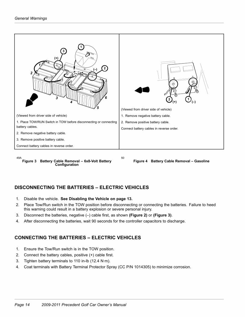
1. Place TOW/RUN Switch in TOW before disconnecting or connectingbattery cables.
2. Remove negative battery cable.
3. Remove positive battery cable.
Connect battery cables in reverse order.
2(+)
1(–)
(Viewed from driver side of vehicle)
1. Remove negative battery cable.
2. Remove positive battery cable.
Connect battery cables in reverse order.
49AFigure 3 Battery Cable Removal – 6x8-Volt Battery
Configuration
50Figure 4 Battery Cable Removal – Gasoline
DISCONNECTING THE BATTERIES – ELECTRIC VEHICLES
1. Disable the vehicle. See Disabling the Vehicle on page 13.2. Place Tow/Run switch in the TOW position before disconnecting or connecting the batteries. Failure to heed
this warning could result in a battery explosion or severe personal injury.3. Disconnect the batteries, negative (–) cable first, as shown (Figure 2) or (Figure 3).4. After disconnecting the batteries, wait 90 seconds for the controller capacitors to discharge.
CONNECTING THE BATTERIES – ELECTRIC VEHICLES
1. Ensure the Tow/Run switch is in the TOW position.2. Connect the battery cables, positive (+) cable first.3. Tighten battery terminals to 110 in-lb (12.4 N·m).4. Coat terminals with Battery Terminal Protector Spray (CC P/N 1014305) to minimize corrosion.
Page 14 2009-2011 Precedent Golf Car Owner’s Manual

General Warnings
RECYCLING LEAD-ACID BATTERIES
WARNING
• Lead-acid batteries contain lead (Pb), other metals, acids and other compounds. If improperly handled,they can contaminate both water and soil, causing environmental damage and personal injury.
Lead-acid batteries are identified by the symbol shown below and should be properly recycled (Figure 5). They cannotbe disposed as municipal waste and must be collected separately. Responsibility for environmental protection must beshared, not only by the manufacturers of the batteries, but by people who use the batteries as well. Please contactyour nearest Club Car dealer or distributor for information on how to properly recycle your batteries.
1403Figure 5 Dispose of Lead-acid Batteries Properly
INTERNATIONAL SAFETY SYMBOLS ON BATTERIES
Anyone using, repairing, or servicing the vehicle must understand and heed the safety symbols on the vehicle batteryor batteries.
1 2 3 4 5 6
1. Shield eyes. 3. No smoking, no open flames, no sparks. 5. Battery acid hazard.
2. Read and follow operating instructions. 4. Keep away from children. 6. Explosive gas hazard.
Refer to General Warnings for more information.
1642Figure 6 International Safety Symbols on Batteries
2009-2011 Precedent Golf Car Owner’s Manual Page 15

General Information
GENERAL INFORMATION
Precedent Golf Cars are available with either electric or gasoline power. Throughout this manual, important featuresunique to each model are highlighted. We urge the owner/operator to read and understand this manual, and to payspecial attention to the features specific to his/her vehicle(s).
MODEL IDENTIFICATION
The serial number of each vehicle is printed on a bar code decal mounted either below the passenger side cup holderor above the accelerator or brake pedal (Example: PH0901-583947) (Figure 7).The two letters (1) at the beginning of the serial number indicate the vehicle model. The following four digits (2)indicate the model year and production week during which the vehicle was built. The six digits (3) following the hyphenrepresent the unique sequential number assigned to each vehicle built within a given model year. See following NOTE.
NOTE: Have the vehicle serial number available when ordering parts or making inquiries.
PH0901-123456BC54679
SERIAL NUMBER
ASSEMBLED IN USA
4
1 2 3
1400Figure 7 Serial Number Decal
SAFETY COMMITTEE
If the golf car is to be rented or is part of a fleet, we strongly recommend that a safety committee be appointed. One ofthe main concerns of this committee should be the safe operation of the golf cars. This should include at a minimum:
• Where golf cars should be driven.
• Ensuring that proper warnings of driving hazards are displayed and visible.
• Who should and who should not drive golf cars.
• Instructing first time drivers.
• Maintaining golf cars in a safe driving condition.
• How various rules are to be enforced.
The safety committee should include all these items and such others as the committee feels necessary or appropriate.
Page 16 2009-2011 Precedent Golf Car Owner’s Manual
Controls and Indicators – Electric Vehicles
CONTROLS AND INDICATORS – ELECTRIC VEHICLES
See General Warnings on page 11.
WARNING
• If renting or loaning the vehicle, make sure the driver is familiar with all controls and operatingprocedures before allowing the vehicle to be driven.
• Do not shift the Forward/Reverse switch while the vehicle is moving. To avoid injury to anunsuspecting passenger or damage to the vehicle, always bring the vehicle to a full stop beforeshifting the Forward/Reverse switch.
• Release the accelerator pedal and then press the brake pedal firmly until the vehicle stops. To avoidunintentionally starting or rolling the vehicle, set the park brake, place the Forward/Reverse switch inthe NEUTRAL position, turn the key switch to the OFF position, and remove the key when leavingthe vehicle.
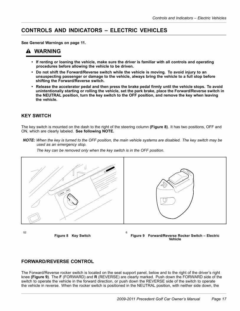
KEY SWITCH
The key switch is mounted on the dash to the right of the steering column (Figure 8). It has two positions, OFF andON, which are clearly labeled. See following NOTE.
NOTE: When the key is turned to the OFF position, the main vehicle systems are disabled. The key switch may beused as an emergency stop.The key can be removed only when the key switch is in the OFF position.
52Figure 8 Key Switch
6Figure 9 Forward/Reverse Rocker Switch – Electric
Vehicle
FORWARD/REVERSE CONTROL
The Forward/Reverse rocker switch is located on the seat support panel, below and to the right of the driver’s rightknee (Figure 9). The F (FORWARD) and R (REVERSE) are clearly marked. Push down the FORWARD side of theswitch to operate the vehicle in the forward direction, or push down the REVERSE side of the switch to operatethe vehicle in reverse. When the rocker switch is positioned in the NEUTRAL position, with neither side down, the
2009-2011 Precedent Golf Car Owner’s Manual Page 17
Controls and Indicators – Electric Vehicles
vehicle will not operate if the accelerator pedal is pressed. The reverse buzzer will sound as a warning when theForward/Reverse switch is in the REVERSE position.
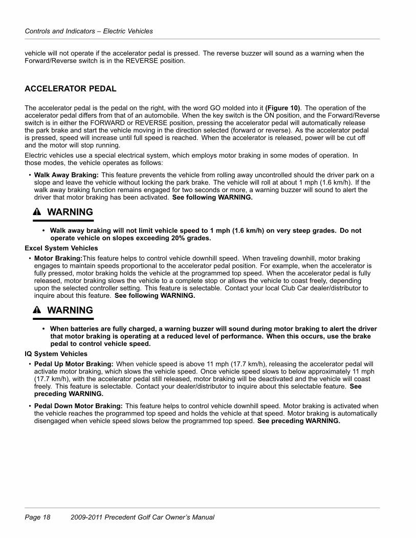
ACCELERATOR PEDAL
The accelerator pedal is the pedal on the right, with the word GO molded into it (Figure 10). The operation of theaccelerator pedal differs from that of an automobile. When the key switch is the ON position, and the Forward/Reverseswitch is in either the FORWARD or REVERSE position, pressing the accelerator pedal will automatically releasethe park brake and start the vehicle moving in the direction selected (forward or reverse). As the accelerator pedalis pressed, speed will increase until full speed is reached. When the accelerator is released, power will be cut offand the motor will stop running.Electric vehicles use a special electrical system, which employs motor braking in some modes of operation. Inthose modes, the vehicle operates as follows:
• Walk Away Braking: This feature prevents the vehicle from rolling away uncontrolled should the driver park on aslope and leave the vehicle without locking the park brake. The vehicle will roll at about 1 mph (1.6 km/h). If thewalk away braking function remains engaged for two seconds or more, a warning buzzer will sound to alert thedriver that motor braking has been activated. See following WARNING.
WARNING
• Walk away braking will not limit vehicle speed to 1 mph (1.6 km/h) on very steep grades. Do notoperate vehicle on slopes exceeding 20% grades.
Excel System Vehicles• Motor Braking:This feature helps to control vehicle downhill speed. When traveling downhill, motor brakingengages to maintain speeds proportional to the accelerator pedal position. For example, when the accelerator isfully pressed, motor braking holds the vehicle at the programmed top speed. When the accelerator pedal is fullyreleased, motor braking slows the vehicle to a complete stop or allows the vehicle to coast freely, dependingupon the selected controller setting. This feature is selectable. Contact your local Club Car dealer/distributor toinquire about this feature. See following WARNING.
WARNING
• When batteries are fully charged, a warning buzzer will sound during motor braking to alert the driverthat motor braking is operating at a reduced level of performance. When this occurs, use the brakepedal to control vehicle speed.
IQ System Vehicles• Pedal Up Motor Braking: When vehicle speed is above 11 mph (17.7 km/h), releasing the accelerator pedal willactivate motor braking, which slows the vehicle speed. Once vehicle speed slows to below approximately 11 mph(17.7 km/h), with the accelerator pedal still released, motor braking will be deactivated and the vehicle will coastfreely. This feature is selectable. Contact your dealer/distributor to inquire about this selectable feature. Seepreceding WARNING.
• Pedal Down Motor Braking: This feature helps to control vehicle downhill speed. Motor braking is activated whenthe vehicle reaches the programmed top speed and holds the vehicle at that speed. Motor braking is automaticallydisengaged when vehicle speed slows below the programmed top speed. See preceding WARNING.
Page 18 2009-2011 Precedent Golf Car Owner’s Manual

Controls and Indicators – Electric Vehicles
77Figure 10 Accelerator Pedal
BRAKE PEDAL
The brake pedal is the large pedal on the left with the word STOP molded into it. To slow or stop the vehicle, pressthe brake pedal with your foot (Figure 11).
78Figure 11 Brake Pedal
79Figure 12 Park Brake Pedal
PARK BRAKE PEDAL
The park brake pedal is the small raised portion in the upper left corner of the brake pedal. It has the word PARKmolded into it. To set the park brake, press the brake pedal firmly and tilt the park brake portion of the pedal forwardwith your foot (Figure 12). See following WARNING and NOTE.
2009-2011 Precedent Golf Car Owner’s Manual Page 19
Controls and Indicators – Electric Vehicles
WARNING
• The park brake will release automatically when either the accelerator or brake pedal is pressed. Thepark brake has multiple locking positions and should be firmly pressed and locked to prevent thevehicle from rolling.
BATTERY WARNING LIGHT
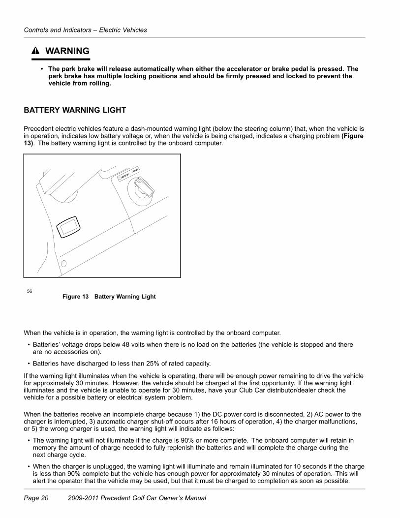
Precedent electric vehicles feature a dash-mounted warning light (below the steering column) that, when the vehicle isin operation, indicates low battery voltage or, when the vehicle is being charged, indicates a charging problem (Figure13). The battery warning light is controlled by the onboard computer.
56Figure 13 Battery Warning Light
When the vehicle is in operation, the warning light is controlled by the onboard computer.
• Batteries’ voltage drops below 48 volts when there is no load on the batteries (the vehicle is stopped and thereare no accessories on).
• Batteries have discharged to less than 25% of rated capacity.
If the warning light illuminates when the vehicle is operating, there will be enough power remaining to drive the vehiclefor approximately 30 minutes. However, the vehicle should be charged at the first opportunity. If the warning lightilluminates and the vehicle is unable to operate for 30 minutes, have your Club Car distributor/dealer check thevehicle for a possible battery or electrical system problem.
When the batteries receive an incomplete charge because 1) the DC power cord is disconnected, 2) AC power to thecharger is interrupted, 3) automatic charger shut-off occurs after 16 hours of operation, 4) the charger malfunctions,or 5) the wrong charger is used, the warning light will indicate as follows:
• The warning light will not illuminate if the charge is 90% or more complete. The onboard computer will retain inmemory the amount of charge needed to fully replenish the batteries and will complete the charge during thenext charge cycle.
• When the charger is unplugged, the warning light will illuminate and remain illuminated for 10 seconds if the chargeis less than 90% complete but the vehicle has enough power for approximately 30 minutes of operation. This willalert the operator that the vehicle may be used, but that it must be charged to completion as soon as possible.
Page 20 2009-2011 Precedent Golf Car Owner’s Manual

Controls and Indicators – Electric Vehicles
• The warning light will repeatedly illuminate for 10 seconds, with 4 second intervals if the charger times out at 16hours and the batteries are not sufficiently charged. This indicates an abnormal charge cycle. The charger andbatteries should be checked by your Club Car distributor/dealer.
• The warning light will repeatedly illuminate for 10 seconds, with 4 second intervals during a charge cycle (DC plug isstill connected) if AC power to the charger is interrupted. The light will go out when AC power is restored.
LED Light: In addition to the warning light, there is an infrared LED in the dash light assembly, which transmits aninfrared signal from the onboard computer (OBC). This signal is received by the optional Communication DisplayModule, which provides information on the condition of the vehicle and batteries.
TOW/RUN SWITCH
WARNING
• Place Tow/Run switch in the TOW position before disconnecting or connecting the batteries. Failure toheed this warning could result in a battery explosion or severe personal injury.
• When the Tow/Run switch is in the TOW position, all motor braking functions, including walk awaybraking, are disabled.
The Precedent electric vehicles are equipped with a Tow/Run switch, located under the seat behind the batteries(Figure 14). The switch must be in the RUN position in order to operate the vehicle. When the switch is in the TOWposition, power to the vehicle electrical components is turned off and the vehicle will not operate. See following NOTE.
NOTE: After placing the Tow/Run switch in the TOW position, allow 10 seconds to elapse before switching back tothe RUN position.After placing the Tow/Run switch in the RUN position, allow 10 seconds to elapse before operating the vehicle.
RUN
TOW
1381Figure 14 Tow/Run Switch
The Tow/Run switch should be placed in the TOW position under the following conditions:
• Before Towing the Vehicle: Place the Tow/Run switch in the TOW position to disable all motor braking functions,thus preventing possible damage that could occur to the vehicle or electrical components if the vehicle is towedwhile the walk away braking motor braking function is operating.
2009-2011 Precedent Golf Car Owner’s Manual Page 21

Controls and Indicators – Gasoline Vehicles
• Before Disconnecting or Connecting Battery Cables: Place the Tow/Run switch in the TOW position to turnoff power to the vehicle electrical system, thus preventing severe arcing and possible battery explosion as thebattery cables are disconnected.
• For Long Term Storage: Place the Tow/Run switch in the TOW position to turn off power to the vehicle electricalsystem, thus preventing vehicle electrical components from discharging the batteries.
CONTROLS AND INDICATORS – GASOLINE VEHICLES
See General Warnings on page 11.
WARNING
• If renting or loaning the vehicle, make sure the driver is familiar with all controls and operatingprocedures before allowing the vehicle to be driven.
• Do not shift the Forward/Reverse handle while the vehicle is moving. To avoid injury to anunsuspecting passenger or damage to the vehicle, always bring the vehicle to a full stop beforeshifting the Forward/Reverse handle.
• Release the accelerator pedal and then press the brake pedal firmly until the vehicle stops. To avoidunintentionally starting or rolling the vehicle, set the park brake, place the Forward/Reverse handle inthe NEUTRAL position, turn the key switch to the OFF position, and remove the key.
• Do not tamper with the governor. Doing so will void the warranty, as well as damage the engine andother components, and could result in property damage, personal injury, or death due to unsafe speed.
KEY SWITCH
The key switch is mounted on the dash to the right of the steering column (Figure 15). It has two positions, OFF andON, which are clearly labeled. See following NOTE.
NOTE: When the key is turned to the OFF position, the main vehicle systems are disabled. The key switch may beused as an emergency stop.The key can be removed only when the key switch is in the OFF position.
52Figure 15 Key Switch
59Figure 16 Forward/Reverse Handle
Page 22 2009-2011 Precedent Golf Car Owner’s Manual

Controls and Indicators – Gasoline Vehicles
FORWARD/REVERSE CONTROL
The Forward/Reverse handle is located on the seat support panel, below and to the right of the driver’s right knee(Figure 16). The handle has three distinct positions: F (FORWARD), N (NEUTRAL), and R (REVERSE). Rotate thehandle towards the driver (FORWARD) to operate the vehicle in the forward direction, or towards the passenger(REVERSE) to operate the vehicle in reverse. When the handle is in the straight up position, (NEUTRAL), the vehiclewill not operate. The engine will stop if it is shifted to this position during operation. Club Car vehicles operate atreduced speed in reverse. The reverse buzzer will sound as a warning when the Forward/Reverse handle is inthe REVERSE position.
ACCELERATOR PEDAL
The accelerator pedal is the pedal on the right, with the word GO molded into it (Figure 17). The operation ofthe accelerator pedal differs from that of an automobile. When the key switch is in the ON position, and theForward/Reverse handle is in either the FORWARD or REVERSE position, pressing the accelerator pedal willautomatically release the park brake and start the vehicle moving in the direction selected (forward or reverse). Asthe accelerator pedal is pressed, speed will increase until full speed is reached. When the accelerator is released,power will be cut off and the motor will stop running.
77Figure 17 Accelerator Pedal
BRAKE PEDAL
The brake pedal is the large pedal on the left with the word STOP molded into it. To slow or stop the vehicle, pressthe brake pedal with your foot (Figure 18).
2009-2011 Precedent Golf Car Owner’s Manual Page 23

Controls and Indicators – Gasoline Vehicles
78Figure 18 Brake Pedal
79Figure 19 Park Brake Pedal
PARK BRAKE PEDAL
The park brake pedal is the small raised portion in the upper left corner of the brake pedal. It has the word PARKmolded into it. To set the park brake, press the brake pedal firmly and tilt the park brake portion of the pedal forwardwith your foot (Figure 19). See following WARNING and NOTE.
WARNING
• The park brake will release automatically when either the accelerator or brake pedal is pressed. Thepark brake has multiple locking positions and should be firmly pressed and locked to prevent thevehicle from rolling.
NOTE: Vehicles equipped with lights: On early 2009 model gasoline vehicles, after the park brake is engaged, thebrake lights may remain illuminated for up to four minutes.
NEUTRAL LOCKOUT
For the convenience of the trained technician, there is a neutral lockout cam located on the back of theForward/Reverse shifter. If the neutral lockout cam is pulled out approximately 3/8 inch (10 mm) and then rotatedone-half turn until it snaps into place, the cam will be in the MAINTENANCE position (Figure 20). This will allow thetechnician to operate the engine in neutral for certain maintenance procedures. With the cam in this position, thevehicle will not operate if the Forward/Reverse handle is placed in either the FORWARD or REVERSE position.
To put the cam back into the OPERATE position, pull the cam out approximately 3/8 inch (10 mm) and rotate it one-halfturn until it snaps into place (Figure 21). See following WARNING and NOTE.
WARNING
• With the cam in the MAINTENANCE position and the engine running, the vehicle may move suddenly ifthe Forward/Reverse handle is shifted or accidentally bumped. To prevent this, chock the front andrear wheels and firmly set the park brake before servicing or leaving the vehicle.
NOTE: Be sure to return the cam to the OPERATE position after servicing the vehicle, or it will not operate with theForward/Reverse handle in either the FORWARD or REVERSE position.
Page 24 2009-2011 Precedent Golf Car Owner’s Manual

Controls and Indicators – Gasoline Vehicles
60Figure 20 Neutral Lockout – Maintenance Position
61Figure 21 Neutral Lockout – Operate Position
CHOKE
The choke is located on the seat support panel below and to the right of the driver’s right knee (Figure 22). If thevehicle is hard to start in cool or cold temperatures, simply push in the choke cover to activate it. Hold it during startup and release the choke cover after the engine starts and runs smoothly.
62Figure 22 Choke
63Figure 23 Low Oil Warning Light
LOW OIL WARNING LIGHT
The gasoline golf car is equipped with a low oil warning light, located on the dash panel just below the steering column(Figure 23). If the warning light comes on, oil should be checked and added to the engine as necessary before
2009-2011 Precedent Golf Car Owner’s Manual Page 25
Pre-Operation and Daily Safety Checklist
continuing to use the vehicle. The vehicle should never be driven with the low oil warning light remaining on. If thewarning light goes on and off, you may proceed, but oil should be added at the first opportunity. If the oil level is correctand the warning light stays on, have a trained technician check the vehicle. See following CAUTION.
CAUTION
• Failure to add oil immediately when the low oil warning light stays on may result in permanentengine damage.
PRE-OPERATION AND DAILY SAFETY CHECKLIST
Each Club Car vehicle has been thoroughly inspected and adjusted at the factory; however, upon receiving your newvehicle(s), you should become familiar with its controls, indicators, and operation. Carefully inspect each vehicle toensure that it is in proper working condition before accepting delivery.Use the following checklist as a guide to inspect the vehicle. This checklist should be used daily to ensure thatthe vehicle is in proper working condition and in conjunction with the Performance Inspection on page 27, and thePeriodic Service Schedules on page 35. Any problems should be corrected by a Club Car distributor/dealer or atrained technician.Any vehicle not functioning correctly should be removed from use until it is properly repaired. This will prevent furtherdamage to the vehicle and avoid the possibility of injury due to unsafe conditions.All Vehicles• General: All the parts should be in place and properly installed. Be sure that all nuts, bolts, and screws are tight.
• Safety and information decals: Check to ensure that all safety and information decals are in place. See SafetyDecal and Feature Identification on page 4.
• Tires: Check for proper tire pressure. Visually inspect tires for wear, damage, and proper inflation on a daily basis.See Vehicle Specifications on page 59.
• Performance Inspection: Inspect as instructed. See Performance Inspection on page 27.Electric Vehicles• Batteries: Check electrolyte to ensure that it is at its proper level (Figure 28, Page 45). Check battery posts. Wiresshould be tight and free of corrosion. Charge batteries fully before first use of vehicle.
• Charger cord, plug, and receptacle: Visually inspect for cracks, loose connections, and frayed wiring. See Plugand Receptacle on page 48.
Gasoline Vehicles• Battery: Check electrolyte to ensure it is at the proper level (Figure 36, Page 52). Check battery posts. Wiresshould be tight and free of corrosion and battery should be fully charged.
• Engine: Check for proper engine oil level. See Engine Oil – Gasoline Vehicles on page 52.
• Fuel: Check fuel level. See Fueling Instructions – Gasoline Vehicles on page 55. Check fuel tank, lines,cap, pump, fuel filters, and carburetor for fuel leakage.
• Exhaust system: Check for leaks.
WARNING
• Be sure the plastic has been removed from the seat bottom before operating the vehicle. Failure to doso may result in a fire, property damage, personal injury, or death.
Page 26 2009-2011 Precedent Golf Car Owner’s Manual
Pre-Operation and Daily Safety Checklist
PERFORMANCE INSPECTION
After you have familiarized yourself with the vehicle controls and have read and understood the driving instructions,take the vehicle for a test drive.Use the following checklist in conjunction with the Daily Pre-Operation and Safety Checklist as a guide to inspect thevehicle and check daily for proper operation. Any problems should be corrected by a Club Car distributor/dealer or atrained technician.All Vehicles• Forward/Reverse switch: Check for proper operation. See Controls and Indicators – Electric Vehicles onpage 17 or Controls and Indicators – Gasoline Vehicles on page 22.
• Brakes: Be sure the brakes function properly. When brake pedal is pressed using moderate pressure, thevehicle should come to a smooth, straight stop. If the vehicle swerves or fails to stop, stops abruptly, or makesa grinding or squeaking noise, have the brake system checked and adjusted as required. Continued, moderatebrake pedal pressure should be able to lock the wheels, but using lesser pressure should also permit a slow,gradual deceleration.
• Park brake: When latched, the park brake should lock the wheels and hold the vehicle stationary (on an incline of20% or less). It should release when either the accelerator or brake pedal is pressed.
• Reverse buzzer: The reverse buzzer will sound as a warning when the Forward/Reverse handle or switch is inthe REVERSE position.
• Steering: The vehicle should be easy to steer and should not have any play in the steering wheel.
• General: Listen for any unusual noises such as squeaks or rattles. Check the vehicle’s ride and performance.Have a Club Car distributor/dealer or a trained technician investigate anything unusual.
Electric Vehicles• Accelerator: With the key switch in the ON position and the Forward/Reverse switch in the FORWARD position, asthe accelerator pedal is pressed, the motor should start and the vehicle should accelerate smoothly to full speed.When the pedal is released it should return to the original position. All Club Car vehicles operate at reducedspeed in reverse.
• Walk Away Braking: With the vehicle parked on level ground and the park brake disengaged, place the Tow/Runswitch in the RUN position and attempt to push the vehicle. Motor braking should engage and cause resistance torolling (moving at no more than 1 to 3 mph) (1.5 to 4.8 km/h) with the Forward/Reverse switch in any position.When walk away motor braking is engaged, the reverse buzzer should emit a distinct pattern of beeps. Seefollowing WARNING.
WARNING
• Walk Away Braking will not limit vehicle speed to 1 mph (1.6 km/h) on very steep grades. Do notoperate vehicle on slopes exceeding 20% grades.
Excel System Vehicles• Motor Braking: Accelerate down an incline with the accelerator pedal fully pressed. When the vehicle reachesmaximum programmed speed, motor braking should engage and limit the vehicle to its maximum programmedspeed. On very steep grades, the vehicle may slightly exceed its maximum programmed speed, requiring the use ofthe brake pedal. Also, travel downhill with the accelerator pedal partially pressed. Motor braking should limit speedto less than top speed and maintain speeds proportional to the accelerator pedal position. On a level surface,accelerate the vehicle to full speed and then release the accelerator pedal. Motor braking should smoothly slow thevehicle to a complete stop or else allow the vehicle to coast freely, depending on the selected controller setting.
IQ System Vehicles• Pedal Up Motor Braking: Accelerate the vehicle to full speed and then release the accelerator pedal. Motorbraking should quickly and smoothly slow the vehicle to approximately 11 mph (17.7 km/h). Motor braking willdisengage when vehicle slows to 11 mph (17.7 km/h).
• Pedal Down Motor Braking: Accelerate down an incline with the accelerator pedal pressed. When the vehiclereaches maximum programmed speed, motor braking should engage and limit the vehicle to its maximum
2009-2011 Precedent Golf Car Owner’s Manual Page 27

Driving Instructions
programmed speed. On very steep grades, the vehicle may slightly exceed its maximum programmed speed,requiring the use of the brake pedal.
Gasoline Vehicles• Accelerator: With the key switch in the ON position and the Forward/Reverse switch in the FORWARD position,as the accelerator pedal is pressed, the engine should start and the vehicle should accelerate smoothly tofull speed. When the pedal is released it should return to the original position. All Club Car vehicles operate atreduced speed in reverse.
• Governor: Check maximum speed of the vehicle. The vehicle should operate at 12-15 mph (19-24 km/h) on alevel surface.
DRIVING INSTRUCTIONS
WARNING
• Only licensed drivers should be allowed to drive the vehicle.• If renting or loaning the vehicle, make sure the driver is familiar with all controls and operatingprocedures before allowing the vehicle to be driven.
• No more than two persons per bench seat should be on the vehicle at one time. Do not allowpassenger to ride in the bag well.
• The vehicle is not specially equipped for handicapped persons. Be sure all persons can properlyoperate the vehicle prior to allowing them to drive the vehicle.
• Be sure all passengers are capable of securing themselves in a vehicle before allowing them toride in one.
• For night use, the vehicle must be equipped with headlights and taillights.• Stop the vehicle before shifting the Forward/Reverse switch. Failure to do so may result in injury to anunsuspecting passenger and (or) damage to the vehicle.
• To help avoid being struck, do not stand in front of or behind the vehicle.• Operate the vehicle from the driver seat only.• To help prevent falls from the vehicle, remain seated in a moving vehicle and hold on to hand holdsor handrails at all times. Driver should keep both hands on the steering wheel when the vehicle isin motion.
• To help prevent the possibility of serious injury, keep your entire body inside the vehicle.• Do not leave children unattended on vehicle.• To help prevent overturning the vehicle, drive slowly straight up and down slopes. Avoid drivingthe vehicle on slopes exceeding 20% incline.
• To help avoid possible injury to an inattentive passenger and (or) damage to the vehicle, avoid suddenstarts, sudden stops, and abrupt turns.
• To help avoid the possibility of losing control of or overturning the vehicle, reduce speed for adversedriving conditions such as wet grass or rough terrain.
• Do not use the vehicle on public roads. It is not designed or intended for street use and should notbe licensed for use on public roads.
• Obey all local rules concerning golf cars.• The vehicle should be driven in only specified areas by trained drivers.• Do not drive while under the influence of alcohol, drugs, or medications.• To prevent overturning the vehicle, drive slowly in turns.• Use brakes to reduce speed when coasting downhill.
WARNING CONTINUED ON NEXT PAGE
Page 28 2009-2011 Precedent Golf Car Owner’s Manual

Driving Instructions
WARNING
• This vehicle is not intended to be used where risk of falling objects exists. If your vehicle will be usedin such an environment, contact your local dealer.
• Do not drive the vehicle under tree limbs, bridges, tunnels, or other objects that are less than 80inches (203 cm) from the ground.
No one should drive the vehicle without first being instructed in the proper operation and use of the vehicle’s controls.An experienced operator should accompany each first-time driver on a test drive before allowing him/her to operatethe vehicle alone.To ensure safe operation of the vehicle, follow exactly and in order, all of the following procedures. Read andunderstand all instructions prior to driving the vehicle.
STARTING THE VEHICLE
1. Study and understand controls.2. Make sure everyone is seated and holding onto seat handles or handrails.3. Read safety and information decals located on the vehicle.4. Make sure wheels are turned in desired direction.5. Turn the key to the ON position and make sure nothing is in your path.6. Select direction by placing Forward/Reverse handle or switch in desired position (F = forward or R = reverse). A
buzzer will sound as a warning when the Forward/Reverse handle or switch is in the REVERSE position.7. Slowly press accelerator pedal. The park brake will release automatically and the vehicle will start to move. As
the accelerator pedal is pressed, speed will increase until full speed is reached. See following WARNING.
WARNING
• Operator must control vehicle speed when going downhill.
Electric vehicles:
• Pedal down or pedal up motor braking may be used to help control speed when going downhill;however, steep terrain or other conditions will require that pedal braking be used in conjunction withmotor braking.
Gasoline Vehicles:
• Do not shift the vehicle out of forward while going downhill. If you do, you will not be able to shiftinto reverse or back into forward until stopped.
• Press the brake pedal as necessary and partially press the accelerator when descending a hill. Withthe accelerator pedal partially pressed, the governor will cause the engine to assist the brakes incontrolling downhill speed.
NOTE: If the Forward/Reverse handle is shifted into the NEUTRAL position, power will be cut off and the enginewill stop running.
STOPPING THE VEHICLE
WARNING
• Driving through water may affect the brakes. After driving through water, check effectiveness of thebrakes by gently pressing the brake pedal. If the vehicle does not slow down at the normal rate,continue to press the brake pedal until the brakes dry out and normal performance returns.
2009-2011 Precedent Golf Car Owner’s Manual Page 29
Towing
CAUTION
• When stopped on a hill, use the brake pedal to hold your position. Do not use the accelerator pedalto hold position.
To stop the vehicle, release the accelerator pedal and press the brake pedal with your right foot until the vehiclecomes to a complete stop.
PARKING AND LEAVING THE VEHICLE
1. After stopping the vehicle, firmly press the park brake pedal until it locks and prevents the vehicle from rolling.See following NOTE.
NOTE: Vehicles equipped with lights: On early 2009 model gasoline vehicles, after the park brake is engaged, thebrake lights may remain illuminated for up to four minutes.
2. Turn the key switch to the OFF position and place the Forward/Reverse handle or switch in the NEUTRALposition. Remove the key when the vehicle is not in use. For gasoline vehicles, also turn off the fuel shut-offvalve (Figure 24).
3. Electric vehicles only: When the Tow/Run switch is in the RUN position, (with the Forward/Reverse switch orkey switch in any position), the walk away braking function will prevent the vehicle from rolling at more than 1 to 3mph (1.5 to 4.8 km/h) unless the accelerator is pressed. This prevents the possibility of a parked vehicle (withthe park brake disengaged) rolling away too fast to be overtaken on foot.
TOWING
WARNING
• Do not tow the vehicle on public streets or highways.• Use only approved Club Car tow bars.• Turn the key switch to OFF and place the Forward/Reverse handle or switch in the NEUTRAL positionbefore towing the vehicle.
• Electric vehicles only: Place the Tow/Run switch in the TOW position; otherwise, the vehicle willnot roll while being towed.
• Extreme caution should be used when towing any vehicle.• Do not exceed 5 mph (8 km/h) towing speed.• Do not allow people in the vehicles being towed.• Avoid sudden starts, sudden stops, and tight turns when towing.• Avoid stopping on a hill when towing. If you must stop on a hill, avoid sudden starts or rollingbackwards and stopping suddenly. Failure to heed this warning could cause the vehicle to overturn,possibly resulting in severe personal injury.
• Do not tow more than one Club Car vehicle with another Club Car vehicle. If more than one vehiclemust be towed, an adequately powered vehicle (tractor or full sized truck) properly fitted, with a towhitch height of 11 inches (28 cm) should be used. Only heavy-duty tow bars should be used formulti-vehicle towing. Never tow more than five vehicles at one time.
• Gasoline vehicles only: Turn the fuel shut-off valve to closed (OFF) position (Figure 24).A light duty tow bar is available for break-down towing and single vehicle towing. A heavy duty tow bar and an onboardtow bar are available for multi-vehicle towing. Observe all of the previous WARNING statements when towing.
Page 30 2009-2011 Precedent Golf Car Owner’s Manual

Transporting on a Trailer
TRANSPORTING ON A TRAILER
WARNING
• For use on public roads, the trailer must meet all federal, state, and local requirements such astaillights, brake lights, etc.
• Do not tow a Club Car vehicle behind a passenger vehicle or truck on a public road unless it is on anapproved trailer.
• The vehicle to be towed should be tied securely to the trailer, with the Forward/Reverse handle orswitch in the NEUTRAL position, the key switch the OFF position, and the park brake firmly pressedand locked to prevent movement.
• Do not allow people in the trailer or vehicle being towed.• Avoid sudden starts, sudden stops, and tight turns when towing.• Avoid stopping on a hill when towing. If you must stop on a hill, avoid sudden starts or rollingbackwards and stopping suddenly. Failure to heed this warning could cause the vehicle to overturn,possibly resulting in severe personal injury.
• When towing on a trailer, normal road speed of the tow vehicle should be reduced.• Because of the added length of the trailer, use caution when making turns.• Remove the vehicle windshield and secure the seat bottom before transporting on a trailer.• Gasoline vehicles only: Turn the fuel shut-off valve to the closed (OFF) position (Figure 24).
If the vehicle must be transported over long distances or on public highways, it should be transported on an approvedtrailer that has the approved load rating of 1200 lb. (544 kg) per vehicle being transported.
NOTE: A two-car trailer should be rated at 2 x 1200 = 2400 lb. (2 x 544 = 1088 kg).
STORAGE – ELECTRIC VEHICLE
See General Warnings on page 11.
WARNING
• Turn the key switch to the OFF position, remove the key, and leave the Forward/Reverse switch inthe NEUTRAL position during storage. Place Tow/Run switch in the TOW position. This is to preventunintentionally starting the vehicle or a fire hazard.
• Do not attempt to charge frozen batteries or batteries with bulged cases. Discard the battery. Frozenbatteries can explode.
CAUTION
• Batteries in a low state of charge will freeze at low temperatures.• To avoid exposing electrical components to moisture and subsequent damages, do not use any typeof pressure washing or steam cleaning equipment to wash the vehicle.
PREPARING THE ELECTRIC VEHICLE FOR EXTENDED STORAGE
1. Fully charge batteries. See Charging Batteries on page 47.2. Batteries should be clean and free of corrosion. Wash tops and terminals of batteries with a solution of baking
soda and water (1 cup (237 mL) baking soda per 1 gallon (3.8 L) of water). Rinse solution off batteries. Do not
2009-2011 Precedent Golf Car Owner’s Manual Page 31
Storage – Electric Vehicle
allow this solution to enter the batteries. Be sure terminals are tight. Let the terminals dry and then coat them withBattery Terminal Protector Spray (CC P/N 1014305).
3. Store vehicle in a cool, dry place. This will minimize battery self-discharge.4. Adjust tires to recommended tire pressure. See Vehicle Specifications on page 59.5. Perform all semiannual periodic lubrication. See Periodic Lubrication Schedules on page 40.6. Thoroughly clean front body, rear body, seats, battery compartment, and underside of vehicle.7. Do not engage the park brake. Chock the wheels to prevent the vehicle from rolling.8. Keep batteries fully charged during storage.
8.1. Leave battery chargers plugged in during storage. The onboard computer (OBC) will automatically activatethe charger when necessary.
8.2. If the battery charger is left plugged in during extended storage, check the electrolyte level and chargerfunction monthly to ensure that proper operation is maintained. To check charger function, disconnect theDC cord (stationary charger) from the vehicle or the AC cord (onboard charger) from the power source, waitfive seconds, then reconnect it. The charger is functioning properly if the ammeter indicates current.
NOTE: The OBC keeps track of the time spent in storage mode. When the OBC detects that the storage chargecycles may have depleted the available electrolyte, it will stop the charger from further operation.Disconnecting then reconnecting the DC cord (stationary charger) or AC cord (onboard charger) indicates theelectrolyte levels have been maintained and allows the OBC to resume operation.While in storage, the Tow/Run switch should be in Tow. When in Tow mode, the amber battery warning lightwill not illuminate. Do not attempt to use the battery light as an indication of battery state while in storage.
8.3. If AC power is off for 7 days or longer, the OBC will not function or charge the vehicle again until it hasbeen restarted. To restart the computer, make sure AC power has been restored, disconnect the DCcord (stationary charger) from the vehicle or the AC cord (onboard charger) from the power source, waitfive seconds, then reconnect it.
CAUTION
• Be sure to check the batteries and charger monthly to maintain correct battery water level and toensure the charger is operating correctly during storage.
8.4. If the charger cannot remain plugged in, AC power will not be available during extended storage, orelectrolyte levels will not be maintained, then disconnect the batteries for storage (Figure 2, Page 13) or(Figure 3, Page 14).
RETURNING THE STORED ELECTRIC VEHICLE TO SERVICE
1. If necessary, connect batteries. See Connecting the Batteries – Electric Vehicles on page 14.2. Fully charge batteries.
WARNING
• Do not attempt to charge frozen batteries or batteries with bulged cases. Discard the battery. Frozenbatteries can explode.
3. Adjust tires to recommended tire pressure. See Vehicle Specifications on page 59.4. Perform the Pre-Operation and Daily Safety Checklist on page 26.
Page 32 2009-2011 Precedent Golf Car Owner’s Manual

Storage – Gasoline Vehicle
STORAGE – GASOLINE VEHICLE
See General Warnings on page 11.
DANGER
• Do not attempt to drain fuel when the engine is hot or while it is running.• Be sure to clean up any spilled gasoline before operating the vehicle.• Store fuel in an approved fuel container only. Store in a well-ventilated area away from sparks, openflames, heaters, or heat sources.
• Keep fuel out of the reach of children.• Do not siphon fuel from the vehicle.
WARNING
• Turn the key switch to the OFF position, remove the key, and leave the Forward/Reverse handle inthe NEUTRAL position during storage. This is to prevent unintentionally starting the vehicle or afire hazard.
• Turn the fuel shut-off valve to closed (OFF) position (Figure 24).
CAUTION
• Batteries in a low state of charge will freeze at low temperatures.
PREPARING THE GASOLINE VEHICLE FOR EXTENDED STORAGE
1. Store vehicle in a cool, dry place. This will minimize battery self-discharge. If the battery appears to be weak,have it charged by a trained technician. Use an automotive-type 12-volt battery charger rated at 10 amps or less.
2. Drain carburetor and seal the fuel tank.2.1. Place the Forward/Reverse handle in the NEUTRAL position and the neutral lockout cam in the
MAINTENANCE position. Turn the fuel shut-off valve to the closed (OFF) position (Figure 24) and runthe engine until fuel remaining in the carburetor and fuel lines is depleted and the engine stalls. Returnthe neutral lockout cam to the OPERATE position.
2.2. Loosen, but do not remove, the carburetor drain screw and drain fuel remaining in bowl into a small, cleancontainer, then pour the fuel from the container into vehicle fuel tank. Tighten the carburetor drain screw.
2.3. Disconnect fuel vent line from fuel tank vent nipple.2.4. Plug the fuel tank vent nipple so that it is air tight. We recommend using a slip-on vinyl cap.
3. Disconnect battery and spark plug wire(s). See Disconnecting the Battery – Gasoline Vehicles on page 13.4. Battery should be clean and free of corrosion. Wash top and terminals of battery with a solution of baking soda
and water (1 cup (237 mL) baking soda per 1 gallon (3.8 L) of water). Rinse solution off battery. Do not allowthis solution to enter the battery. Let the terminals dry and then coat them with Battery Terminal ProtectorSpray (CC P/N 1014305).
5. To protect the engine, remove spark plug and pour 1/2 ounce (14.2 mL) of SAE 10 weight oil into the enginethrough the spark plug hole. Rotate engine crankshaft by hand several times and then install the spark plug.
6. Adjust tires to recommended tire pressure. See Vehicle Specifications on page 59.7. Perform semiannual periodic lubrication. See Periodic Lubrication Schedules on page 40.8. Thoroughly clean front body, rear body, seats, engine compartment, and underside of vehicle.9. Do not engage the park brake. Chock the wheels to prevent the vehicle from rolling.
2009-2011 Precedent Golf Car Owner’s Manual Page 33

Maintenance
1
2
3
1. Fuel Shut-off Valve 2. Closed (OFF) 3. Open (ON) NOTE: Whenselecting valve position, ensure that it is fully opened or fully closed.
1
1. Fuel Shut-off Valve
614Figure 24 Fuel Shut-off Valve
63AFigure 25 Fuel Tank
RETURNING THE STORED GASOLINE VEHICLE TO SERVICE
1. Restore the fuel systems to operation (Figure 25).1.1. Remove the plug from the fuel tank vent.1.2. Connect the vent tube to the fuel tank vent.
2. Connect battery and spark plug wire(s). See Connecting the Battery – Gasoline Vehicles on page 13.3. Completely open the fuel shut-off valve (1) (Figure 24). Make sure the valve is fully open. A partially closed fuel
shut-off valve combined with the use of the choke can result in a fouled spark plug and engine failure.4. Place the Forward/Reverse handle in the NEUTRAL position and the neutral lockout cam in the MAINTENANCE
position. Crank the engine until fuel is pumped into the carburetor and fuel lines and the engine starts. Turn theengine off and return the neutral lockout cam to the OPERATE position. See following NOTE.
NOTE: Due to the oil added to the engine in preparation for storage, engine may smoke excessively for a shorttime when it is run for the first time after storage.
5. Adjust tires to recommended tire pressure. See Vehicle Specifications on page 59.6. Perform the Pre-Operation and Daily Safety Checklist on page 26.
MAINTENANCE
See General Warnings on page 11.To ensure trouble-free vehicle performance, it is very important to follow an established preventive maintenanceprogram. Regular and consistent vehicle maintenance can prevent vehicle downtime and expensive repairs that canresult from neglect. Use the Pre-Operation and Daily Safety Checklist beginning on page 27, the Performance
Page 34 2009-2011 Precedent Golf Car Owner’s Manual
Periodic Service Schedules
Inspection, and the following Periodic Service Schedules and Periodic Lubrication Schedules to keep the vehicle inproper working condition.Any vehicle not functioning correctly should be removed from use until it is properly repaired. This will prevent furtherdamage to the vehicle and avoid the possibility of injury due to unsafe conditions.Contact your local Club Car distributor/dealer to perform all repairs and semiannual and annual periodic service.
WARNING
• If any problems are found during scheduled inspection or service, do not operate the vehicle untilrepairs are made. Failure to make necessary repairs could result in fire, property damage, severepersonal injury, or death.
• Only trained technicians should service or repair the vehicle or battery charger. Anyone doing evensimple repairs or service should have knowledge and experience in electrical and mechanical repair.The appropriate instructions must be used when performing maintenance, service, or accessoryinstallation.
Electric vehicles:
• Hot! Do not attempt to service hot motor. Attempting to do so could cause severe burns.• To avoid unintentionally starting the vehicle, disconnect the batteries and discharge the controller.See Disconnecting the Batteries – Electric Vehicles on page 14.
Gasoline vehicles:
• Moving parts: Do not attempt to service gasoline vehicle while the engine is running.• Hot! Do not attempt to service hot engine or exhaust system. Failure to heed this warning couldresult in severe burns.
• Turn the fuel shut-off valve to the closed (OFF) position (Figure 24).• To avoid unintentionally starting the vehicle, disconnect battery and spark plug wire(s). SeeDisconnecting the Battery – Gasoline Vehicles on page 13.
• Frame ground – Do not allow tools or other metal objects to contact frame when disconnectingbatteries or other electrical wiring. Never allow a positive wire to touch the vehicle frame, engine,or other metal component.
PERIODIC SERVICE SCHEDULES
WARNING
• Service, repairs, and adjustments must be made per instructions in the maintenance and servicemanual.
NOTE: If the vehicle is constantly subjected to heavy use or severe operating conditions, the preventive maintenanceprocedure should be performed more often than recommended in the periodic service and lubricationschedules.Both the Periodic Service Schedule and Periodic Lubrication Schedule must be followed to keep vehicle inoptimum operating condition.
2009-2011 Precedent Golf Car Owner’s Manual Page 35

Periodic Service Schedules
PERIODIC SERVICE SCHEDULE – ELECTRIC VEHICLES
REGULAR INTERVAL SERVICE
Pre-Operation and Daily Safety Checklist See Pre-Operation and Daily SafetyChecklist on page 26.
Performance Inspection See Performance Inspection on page 27.
Daily service by owner
Batteries Charge batteries (after each daily use only).
Weekly service by ownerBatteries (For vehicles NOT equipped with theSingle-Point Watering System)
Check electrolyte level. Add water ifnecessary. See Battery Care – VehiclesWithout the Single-Point Watering Systemon page 44.
Batteries (For vehicles equipped with theSingle-Point Watering System). Water monthlyor according to the established wateringinterval.
Water the batteries. Observe that water flowoccurs and no water overflows from any cell.See Battery Care – Vehicles Equipped withthe Single-Point Watering System on page43.
Batteries
Wash battery tops and clean terminals withbaking soda/water solution. Apply BatteryTerminal Protector Spray (CC P/N 1014305) tobattery terminals.
TiresCheck air pressure and adjust if necessary.See Vehicle Specifications on page 59.
Monthly service by owner or trainedtechnician
General VehiclesThoroughly wash vehicle including theunderside.
Initial (one-time) inspection by owner ortrained technician after six weeks of use
Batteries (For vehicles newly equipped withthe Single Point Watering System)
For vehicles newly equipped with the SPWS,manually check battery electrolyte levels ofall cells to verify correct valve operation. Seepage 42.
Check brake shoes; replace if necessary.
Lubricate brake system per LubricationSchedule.
Check brake cables for damage; replace ifnecessary.
Brake system
Check brake cable equalizer adjustment;adjust if necessary.
Electrical wiring and connectionsCheck for tightness and damage; replace ifnecessary.
Semiannual service by trained technicianonly (every 50 hours of operation or 100rounds of golf)
Front wheel alignment and camber
Check and adjust as required. See Section7 – Steering and Front Suspension inthe appropriate maintenance and servicemanual.
Annual service by owner or trainedtechnician (every 100 hours of operation or200 rounds of golf)
Batteries (For vehicles equipped with theSingle Point Watering System)
Manually check battery electrolyte levels ofall cells to verify correct valve operation. Seepage 42.
Page 36 2009-2011 Precedent Golf Car Owner’s Manual

Periodic Service Schedules
PERIODIC SERVICE SCHEDULE – ELECTRIC VEHICLES
REGULAR INTERVAL SERVICE
BatteriesIf batteries are not performing as expected,see Batteries in the maintenance and servicemanual.
Pedal groupLubricate all rotating joints. See PeriodicLubrication Schedules on page 40.
Annual service by trained technician only(every 100 hours of operation or 200 roundsof golf)
General VehicleCheck for loose hardware; tighten if necessary.Refer to the appropriate maintenance andservice manual.
2009-2011 Precedent Golf Car Owner’s Manual Page 37

Periodic Service Schedules
PERIODIC SERVICE SCHEDULE – GASOLINE VEHICLES
REGULAR INTERVAL SERVICE
Pre-Operation and Daily Safety ChecklistSee Pre-Operation and Daily SafetyChecklist on page 26.Daily service by owner
Performance Inspection See Performance Inspection on page 27.
Check engine oil level; change if necessary.Properly dispose of used oil. See PeriodicLubrication Schedules on page 40.
Engine Check engine cooling air intake; clean ifnecessary. Visually inspect the unshroudedarea around engine exhaust for grass anddebris, and clean if necessary.
TiresCheck air pressure and adjust as necessary.See Vehicle Specifications on page 59.
Monthly service by owner or trainedtechnician
General vehicleWash engine compartment and underside ofvehicle. Do not wash engine when hot.
Battery
Clean terminals and wash dirt from casing;Apply Battery Terminal Protector Spray (CCP/N 1014305) to battery terminals; checkelectrolyte level. See Battery – GasolineVehicles on page 51.
Front wheel alignment and camber
Check and adjust if necessary. See Section7 – Steering and Front Suspension inthe appropriate maintenance and servicemanual.
Electrical wiring and connectionsCheck for tightness and damage; replace ifnecessary.
Check brake shoes; replace if necessary.
Lubricate brake system per LubricationSchedule.
Check brake cables for damage; replace ifnecessary.
Semiannual service by trained technicianonly (every 50 hours of operation or every100 rounds of golf)
Brake system
Check brake cable equalizer adjustment;adjust if necessary.
Check for leaks around gaskets, fill plugs, etc.
Engine Inspect, clean and regap spark plug; replaceif necessary.
Check air filter element; replace if necessary.
Engine air intake system Check clamps for tightness; check hose forcracks.
Pedal groupLubricate all rotating joints. See PeriodicLubrication Schedules on page 40.
Annual service by trained technician only(every 100 hours of operation or every 200rounds of golf)
Page 38 2009-2011 Precedent Golf Car Owner’s Manual

Periodic Service Schedules
PERIODIC SERVICE SCHEDULE – GASOLINE VEHICLES
REGULAR INTERVAL SERVICE
General vehicleCheck for loose hardware; tighten if necessary.Refer to the appropriate maintenance andservice manual.
Two year service by trained technician only(every 200 hours of operation or every 400rounds of golf)
Fuel filters Replace. Dispose of used filters properly.
WARNING
• If any problems are found during scheduled inspection or service, do not operate the vehicle untilrepairs are made. Failure to make necessary repairs could result in fire, property damage, severepersonal injury, or death.
2009-2011 Precedent Golf Car Owner’s Manual Page 39

Periodic Lubrication Schedules
PERIODIC LUBRICATION SCHEDULES
PERIODIC LUBRICATION SCHEDULE – ELECTRIC VEHICLES
REGULAR INTERVAL SERVICELUBRICATION
POINTSRECOMMENDED LUBRICANT
Charger receptacle 1 WD-40
Brake system, per maintenance andservice manual.
2Dry Moly Lube (CC P/N 1012151), whitelithium grease NLGI #2
Semiannually by owner ortrained technician (every 50hours of operation or 100rounds of golf)
Front suspension (two fittings) Chassis Lube - EP NLGI Grade 2
Check/fill transaxle to plug level22 oz. (0.67 liters) SAE 30 WT. API Class SE,SF, or SG Oil (or higher)
Annually by trained technicianonly (every 100 hours ofoperation or 200 rounds ofgolf) Pedal group (as required)
Dupont™ Performance Dry Multi-UseLubricant
64Figure 26 Lubrication Points – Electric Vehicles
Page 40 2009-2011 Precedent Golf Car Owner’s Manual

Periodic Lubrication Schedules
PERIODIC LUBRICATION SCHEDULE – GASOLINE VEHICLES
REGULAR INTERVAL SERVICELUBRICATION
POINTSRECOMMENDED LUBRICANT
Shifter cable pivots 1 Dry Moly Lube (CC P/N 1012151)
Brake system, per maintenance andservice manual.
2Dry Moly Lube (CC P/N 1012151), whitelithium grease NLGI #2
Semiannually by owner ortrained technician (every 50hours of operation or every100 rounds of golf)
Front suspension (two fittings) Chassis Lube - EP NLGI Grade 2
Check/fill unitized transaxle to pluglevel
27 oz. (0.8 liter) 80-90 WT. API Class GL-3or 80-90 WT. AGMA Class EP Gear Lube
Annually by trained technicianonly (every 100 hours ofoperation or every 200 roundsof golf) Pedal group (as required)
Dupont™ Performance Dry Multi-UseLubricant
First change 100 hours –additional change every200 hours of operation (orevery 400 rounds of golf), orannually, whichever comesfirst
Change engine oil and oil filter(dispose of properly)
32 oz. (0.95 liter) without filter; 38 oz. (1.12liters) with filter
65Figure 27 Lubrication Points – Gasoline Vehicles
2009-2011 Precedent Golf Car Owner’s Manual Page 41

Batteries – Electric Vehicles
BATTERIES – ELECTRIC VEHICLES
See General Warnings on page 11.
DANGER
• Battery – Explosive gases! Do not smoke. Keep sparks and flames away from the vehicle and servicearea. Ventilate when charging or operating vehicle in an enclosed area. Wear a full face shield andrubber gloves when working on or near batteries.
• Charge batteries in a well-ventilated area only. Batteries emit hydrogen while being charged. Hydrogenis an explosive gas and must never exceed a level of 2% of the air.
• Battery – Poison! Contains acid! Causes severe burns. Avoid contact with skin, eyes, or clothing.Antidotes:
– External: Flush with water. Call a physician immediately.
– Internal: Drink large quantities of milk or water followed with milk of magnesia or vegetableoil. Call a physician immediately.
– Eyes: Flush with water for 15 minutes. Call a physician immediately.
WARNING
• Wear safety glasses or approved eye protection when servicing the vehicle or battery charger. Wear afull face shield and rubber gloves when working on or near batteries.
• Use insulated tools when working near batteries or electrical connections. Use extreme caution toavoid shorting of components or wiring.
CAUTION
• On all vehicles, turn off all accessories before charging batteries.
NOTE: Recycle or dispose of discarded batteries in accordance with local, state, and federal regulations.
Club Car electric vehicles use deep-cycle batteries. Automotive batteries should never be used in electric vehicles.New batteries will not deliver their full capabilities until they have been discharged and recharged 20 to 50 times. Toobtain the maximum service life from new batteries, restrict electric vehicles with new batteries to 36 holes of usebetween charges in the first two months of operation. Batteries should be fully charged before first use of new vehicle,before first use of a vehicle after storage, and before releasing vehicle for use each day.
WATER QUALITY
To keep batteries in good working condition, the purity of water used is very important. Distilled water is quite pureand is the most common type of water used in batteries. Other acceptable types are deionized water and water fromreverse osmosis. Ordinary tap water should not be used because it contains an excessive amount of impurities thatwill degrade battery performance.Distilled water is produced by distillation, a process in which water is boiled, the steam is collected and then condensedback into water. This process creates a finished product free of minerals, having left all the impurities in the originalwater sample. Club Car, along with our battery manufacturers, highly recommends that distilled water be used inelectric vehicle batteries.Deionized water is the purest form of water, but it is also the most expensive. Deionization removes all ionizableparticles (organic and inorganic) from water through ion exchange. Positively and negatively charged ions are removedfrom the water and replaced with H+ and OH- ions. When these two ions are combined, they form H2O, or purifiedwater.
Page 42 2009-2011 Precedent Golf Car Owner’s Manual

Batteries – Electric Vehicles
Reverse osmosis is a method of removing solids from water by forcing it through a membrane. The membranerejects all solids while allowing purified water to pass through. The choice of membrane determines the amountof impurities that the water may contain.Water from municipal supplies, ponds and wells usually contain detrimental levels of dissolved minerals and chemicals.If using tap water, it is important to use an in-line deionizer to remove impurities that can damage batteries andsignificantly reduce battery life. If tap water is used without a deionizer, regular water analyses must be conducted tocheck for impurities because water companies commonly revise their additives on a periodic basis. The followingchart lists the maximum allowable minerals, solids, and contaminates in parts per million and their impact on batteryperformance. Your local water company should be able to perform testing and compare their results to the chart.If using tap water, Club Car’s Service Parts Department offers two different deionizer systems: one for vehiclesequipped with the Single Point Water System (SPWS) CC P/N AM1240701 and the other for vehicles without SPWS,CC P/N AM10974.
IMPURITY ALLOWABLE CONTENT (PARTSPER MILLION) EFFECTS OF IMPURITY
Suspended matter Trace -
Total solids 100.0 -
Organic and volatile matter 50.0 Corrosion of positive plates
Ammonia 8.0 Slight self-discharge of both plates
Antimony 5.0Self-discharge, reduces life, lower
on-charge voltage
Arsenic 0.5 Self-discharge, can form poisonous gas
Calcium 40.0 Increase of positive plate shedding
Chloride 5.0Loss of capacity in plates, greater loss
in positive plates
Copper 5.0Increased self-discharge, lower
on-charge voltage
Iron 3.0Increased self-discharge, lower
on-charge voltage
Magnesium 40.0 Reduced life
Nickel None allowed Intense lowering of on-charge voltage
Nitrates 10.0 Increased sulfation of negative plate
Nitrates 5.0 Plate corrosion, loss of capacity, reduced life
Platinum None allowed Violent self-discharge, lower on-charge voltage
Selenium 2.0 Positive plate shedding
Zinc 4.0 Slight self-discharge of negative plates
BATTERY CARE – VEHICLES EQUIPPED WITH THE SINGLE-POINT WATERING SYSTEM
WARNING
• When replacing batteries in the Single Point Watering System, place the battery cap from the newreplacement battery onto the used battery being removed from the car. Important safety warnings onthe battery cap must remain with the battery after it has been removed from the car.
To keep batteries in good working condition, follow this maintenance program on a regular basis:
2009-2011 Precedent Golf Car Owner’s Manual Page 43
Batteries – Electric Vehicles
1. Keep the batteries clean and free of corrosion. Wash tops and terminals of batteries with a solution of bakingsoda and water (1 cup (237 mL) baking soda per gallon (3.8 L) of water). Rinse solution off of the batteries. Donot allow this solution to enter the battery. Be sure terminals are tight. Let the terminals dry and then coat withBattery Terminal Protector Spray (CC P/N 1014305). See following NOTE.
NOTE: Dispose of waste water properly.
2. The battery hold-downs should be tight enough so that the batteries do not move while the vehicle is in motion, butnot so tight as to crack or buckle the battery case. For 12-volt batteries, tighten hold-down retaining nuts to 72 in-lb(8.1 N·m). For 8-volt batteries, tighten hold-down retaining nuts to 106 in-lb (12 N·m). The terminal connectionsshould be clean and tight, and any worn insulation or frayed wires should be replaced. Tighten battery terminalsto proper torque. See Connecting the Batteries – Electric Vehicles on page 14. See following WARNING.
WARNING
• If battery wire terminals are damaged or corroded, replace or clean them as necessary. Failure todo so may cause them to overheat during operation and could result in fire, property damage, orpersonal injury.
3. After use, charge the batteries. The batteries should never be left discharged any longer than absolutelynecessary (do not leave discharged overnight).
4. Water the batteries monthly or according to the watering interval. See Establishing the Watering Interval forNew Vehicles on page 44. See Watering Batteries with the SPWS on page 49.
CAUTION
• The watering interval must adequately maintain the electrolyte level above the top of the plates. SeeFigure 28.
• Water the batteries only AFTER charging.Establishing the Watering Interval for New VehiclesIf you do not already have a battery watering interval for your vehicles, manually check the battery water level weeklyto establish the correct watering interval. Thereafter, water batteries according to the established interval. Duringperiods of heavy use, add additional watering as required.Single-Point Watering System Maintenance1. For vehicles newly equipped with the Single-Point Watering System, the initial electrolyte level check on all
battery cells verifies that all the valves in the SPWS are functioning correctly. See Periodic Service Scheduleson page 35. If a valve fails to open, the cell will eventually dry out. The initial one-time inspection of all cellswill identify any occurrence of a valve that fails to open. If a valve fails to close, it will become evident due tothe cell overflowing during routine watering. Either failure scenario is rare, but should be monitored in the initialinspection and during routine watering sessions. Replace malfunctioning valves to ensure maximum batterylife. See following CAUTION.
CAUTION
• After checking the electrolyte, fully tighten the battery caps to prevent electrolyte leakage.2. After the initial six-week inspection, manually check the electrolyte level at least once per year, particularly after
long-term storage or any other period of vehicle inactivity. See preceding CAUTION.
BATTERY CARE – VEHICLES WITHOUT THE SINGLE-POINT WATERING SYSTEM
To keep batteries in good working condition, follow this maintenance program on a regular basis:
1. Keep the batteries clean and free of corrosion. Wash tops and terminals of batteries with a solution of bakingsoda and water (1 cup (237 mL) baking soda per gallon (3.8 L) of water). Rinse solution off of the batteries. Do
Page 44 2009-2011 Precedent Golf Car Owner’s Manual

Batteries – Electric Vehicles
not allow this solution to enter the battery. Be sure terminals are tight. Let the terminals dry and then coat withBattery Terminal Protector Spray (CC P/N 1014305). See following NOTE.
NOTE: Dispose of waste water properly.
2. Check the electrolyte level weekly (Figure 28). Add water only after charging unless the electrolyte level is belowthe top of the plates. In this case, add just enough water to cover the plates, charge, and then check the levelagain. Never charge batteries if plates are exposed above electrolyte level. For best battery life, add onlydistilled water. See following CAUTION and NOTE.
CAUTION
• Do not overfill the batteries.
NOTE: A battery watering gun or bottle is available at many auto parts dealers.
3. The battery hold-downs should be tight enough so that the batteries do not move while the vehicle is in motion, butnot so tight as to crack or buckle the battery case. For 12-volt batteries, tighten hold-down retaining nuts to 72 in-lb(8.1 N·m). For 8-volt batteries, tighten hold-down retaining nuts to 106 in-lb (12 N·m). The terminal connectionsshould be clean and tight, and any worn insulation or frayed wires should be replaced. Tighten battery terminalsto proper torque. See Connecting the Batteries – Electric Vehicles on page 14. See following WARNING.
WARNING
• If battery wire terminals are damaged or corroded, replace or clean them as necessary. Failure todo so may cause them to overheat during operation and could result in fire, property damage, orpersonal injury.
4. After use, charge the batteries. The batteries should never be left discharged any longer than absolutelynecessary (do not leave discharged overnight).
1
3
2
1. Level Indicator 2. Cap 3. Plates
Electrolyte level at least 1/2 inch (13 MM) above plates or tolevel indicator.
17Figure 28 Battery Electrolyte Level
2009-2011 Precedent Golf Car Owner’s Manual Page 45

Battery Charger – Electric Vehicles
BATTERY CHARGER – ELECTRIC VEHICLES
DANGER
• The charging area must be ventilated. Hydrogen level in the air must never exceed 2%. The totalvolume of air in the charging area must be changed five times per hour. Exhaust fans should belocated at the highest point of the roof. Contact a local HVAC engineer.
• Do not charge the vehicle batteries with the vehicle covered or enclosed. Any enclosure or covershould be removed or unzipped and pulled back when batteries are being charged. An accumulationof hydrogen gas could result in an explosion.
WARNING
• Only trained technicians should repair or service the charger. Contact your nearest Club Cardistributor/dealer.
• Each charger should have its own dedicated 15 or 20 ampere separately protected (circuit breaker orfuse) single phase branch circuit, in accordance with all applicable electrical codes for the location.
• Connect the charger AC supply cord to a properly grounded, three-wire outlet of the proper voltageand frequency as shown on the charger.
• Do not use an adapter to plug the charger with a three-prong plug into a two-prong outlet. Improperconnection of the equipment-grounding conductor can result in a fire or an electrical shock.
• An extension cord or electrical outlet must accept a three-prong plug. Extension cord should be athree-wire No. 12 AWG (American Wire Gauge) or no. 14 (British Standard Wire Gauge), and be asshort as possible (no more than 12 feet (3.7 m)). The use of improper extension cord could resultin fire or an electrical shock.
• Do not operate the charger if it has received a sharp blow, was dropped, or otherwise damagedin any way.
• Have worn, cut, or damaged power cords or wires replaced immediately.• Do not use near fuels, grain dust, solvents, thinners, or other flammables. Chargers can igniteflammable materials and vapors.
• Do not expose to rain or any liquid. Keep the charger dry.• Never push objects of any kind into the charger through cabinet slots. They may touch dangerousvoltage points or cause an electrical short circuit that could result in fire or electrical shock.
• Do not connect a stationary charger to the receptacle if the charger cord, plug, or the vehiclereceptacle is broken, damaged, or does not make a good electrical connection. Fire or personal injurycan result. Have a qualified technician replace the parts.
• When the charger is on, the charger DC cord may be disconnected from the vehicle receptacle slowly.Jerking or pulling the DC cord out quickly could cause arcing and burning that could damage the plugand receptacle and could cause batteries to explode.
• Do not block or cover the charger ventilation slots. The slots provide ventilation and protect thecharger from overheating.
• Do not allow clothing, blankets, or other material to cover the charger.• Do not allow the charger to operate for more than 30 minutes at 19 or more amperes.• Install surge arrestors on incoming AC power lines. Surge arrestors will help protect electricalcomponents in the charger and on the vehicle from all but direct or close lightning strikes.
NOTE: Because the vehicle’s onboard computer (OBC) has a storage charge feature that automatically checksand recharges the batteries as necessary every 15 days, the charger can remain plugged to the vehiclethroughout the storage period.
Page 46 2009-2011 Precedent Golf Car Owner’s Manual
Battery Charger – Electric Vehicles
At one hour and at two hours into the charge cycle, the charger will shut off in order to run a self-diagnosticprogram (ammeter will drop to zero). Charging will resume in a few moments (ammeter returns to previousrate of charge).
Each electric vehicle is supplied with a fully automatic battery charger as standard equipment. The AC cord to eachcharger is to be connected to a source capable of supplying 15 amperes minimum per charger.To reduce the risk of electric shock, the battery charger must be grounded. The charger is equipped with an AC electriccord having an equipment-grounding conductor and a grounding type plug. The AC plug must be connected to anappropriate receptacle that is properly installed and grounded in accordance with the National Electrical Code and alllocal codes and ordinances. See the owner’s manual supplied with the charger for specific operating instructionsbefore using the charger.The use of an extension cord with the charger should be avoided. If an extension cord must be used, use athree-conductor no. 12 AWG (American Wire Gauge) or no. 14 SWG (British Standard Wire Gauge), heavy-duty cordwith ground, properly wired and in good electrical condition. Keep it as short as possible (no more than 12 feet (3.7m)). Place all cords so they will not be stepped on, tripped over, or otherwise subject to damage or stress.Ensure that the charger ventilation slots are unobstructed and that there is adequate ventilation.
CHARGING BATTERIES
WARNING
• Be sure all wire connections at the receptacle and the fuse link are clean and tight.• Do not rock or bend the plug. To connect the charger plug to the vehicle receptacle, grasp the plughandle and push the plug straight into the receptacle (Figure 29, Page 48).
• Do not pull on the DC cord (Figure 30, Page 48). Do not twist, rock or bend the plug. To disconnectthe charger plug from the vehicle receptacle, grasp the plug by the handle and pull the plug straightout of the receptacle.
• Do not connect a charger to the receptacle if the charger cord, plug, or the vehicle receptacle isbroken, damaged in any manner, or does not make a good electrical connection. Fire or personalinjury can result. Have it replaced by a qualified service person immediately.
• Failure to follow these instructions could result in damage to the charger cord, the plug, and (or)the vehicle receptacle.
• Do not use a charger if:– The plug is too loose or does not make a good connection.
– The plug and receptacle feel hotter than normal during charge.
– The plug pins or receptacle contacts are bent or corroded.
– The plug, receptacle, or cords are cut, worn, have any exposed wires or are damaged in any way.
• Using the charger with any of the above symptoms could result in a fire, property damage, personalinjury, or death.
NOTE: When temperatures fall below 65 °F (18.3 °C), batteries charged in unheated areas should be placed oncharge as soon as possible after use. Batteries are warmest immediately after use, and cold batteriesrequire more time to fully charge.
Insert the charger DC plug into the vehicle receptacle. The charger will turn on two to ten seconds later (Figure29, Page 48).
When inserting the DC plug, align the raised guide on the plug with the guide slot in the receptacle and pushstraight in slowly.
2009-2011 Precedent Golf Car Owner’s Manual Page 47

Battery Charger – Electric Vehicles
Club Car battery chargers interact with the vehicle onboard computer. The computer records the amount of energyconsumed during vehicle use. While the charger is plugged in, the vehicle’s control circuit is locked out, preventingoperation of the vehicle, as well as the possibility of consequent damage to the charger and the vehicle.
Once the lockout is actuated, the charger turns on. The onboard computer then records the amount of energy beingreturned to the batteries. When the optimum amount of energy needed to replenish the batteries is returned, thecharger will shut off. The control circuit lockout remains activated until the charger plug is disconnected from the vehicle.
Only Club Car PowerDrive battery chargers are compatible with Precedent electric vehicles.
As long as the charger is allowed to shut off by itself, the batteries will be fully charged. Overcharging andundercharging will normally be prevented.
Batteries should be put on charge even if they have been used for only a short period (9 holes of golf or 10 minutes).The charger is automatic and will turn off when batteries are fully charged. If the charger does not seem to be operatingproperly, or if the batteries seem weak, contact your local Club Car distributor/dealer.
66Figure 29 Correct Insertion of Charger DC Plug
67Figure 30 Incorrect Removal of Charger DC Plug
PLUG AND RECEPTACLE
The charger cord, plug, and receptacle are wear items and should be inspected daily. Visually inspect them for cracks,loose connections, and frayed wiring; they must be replaced when worn or damaged. If charger plug or receptacleshow signs of corrosion or the plug is difficult to insert or remove, the receptacle contacts and plug terminals shouldbe cleaned with a good electrical contact cleaner or lightly sprayed with WD-40® brand spray lubricant. The plugshould then be inserted and removed several times to ensure ease of insertion, ease of removal, and good electricalcontact. See following NOTE.
NOTE: If the warning tag has been damaged or removed from the DC cord, have it replaced immediately.
Page 48 2009-2011 Precedent Golf Car Owner’s Manual

Single Point Watering System (SPWS)
SINGLE POINT WATERING SYSTEM (SPWS)
WARNING
• When replacing batteries in the Single Point Watering System, place the battery cap from the newreplacement battery onto the used battery being removed from the car. Important safety warnings onthe battery cap must remain with the battery after it has been removed from the car.
CAUTION
• Water the batteries only AFTER charging.• Use the water deionizer equipment (CC P/N AM1240701) to water batteries with the SPWS.
WATERING BATTERIES WITH THE SPWSChecking the Water Flow Rate1. Connect the water hose with the built-in screen filter (2) to the water faucet (1) (Figure 31). See following
CAUTION.
CAUTION
• Make sure the screen filter is clean.• Do not use a longer garden hose than provided with the System (20 feet), as a decrease in waterpressure could overfill the batteries and damage the refill system.
2. Before screwing the hose-end assembly (3) onto the opposite end of the water hose, check the screen filter (4)inside the end of the assembly to make sure it is clean (Figure 31).
3. Connect the purger (5) to the female coupler (8) on the end of the hose-end assembly (Figure 32).
1
2
3
5
4
5
7
6
8
3
68Figure 31 Connecting Hose with Filter to Water Source
69Figure 32 Checking the Water Flow Rate
4. Completely open the water faucet until the water flows out of the hose-end assembly (3), and note the movementof the red flow indicator balls (6). See following NOTE.
NOTE: The water flow rate must be at least two gallons-per-minute for the SPWS to function properly.
2009-2011 Precedent Golf Car Owner’s Manual Page 49
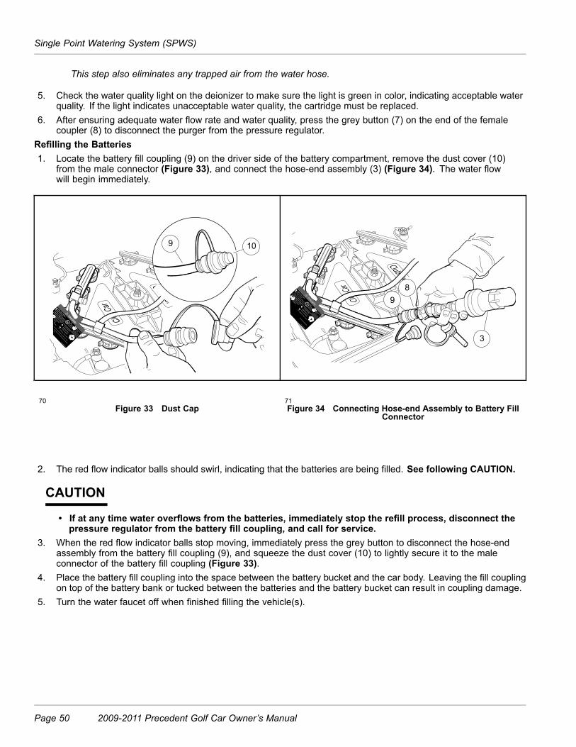
Single Point Watering System (SPWS)
This step also eliminates any trapped air from the water hose.
5. Check the water quality light on the deionizer to make sure the light is green in color, indicating acceptable waterquality. If the light indicates unacceptable water quality, the cartridge must be replaced.
6. After ensuring adequate water flow rate and water quality, press the grey button (7) on the end of the femalecoupler (8) to disconnect the purger from the pressure regulator.
Refilling the Batteries1. Locate the battery fill coupling (9) on the driver side of the battery compartment, remove the dust cover (10)
from the male connector (Figure 33), and connect the hose-end assembly (3) (Figure 34). The water flowwill begin immediately.
10 9
8
9
3
70Figure 33 Dust Cap
71Figure 34 Connecting Hose-end Assembly to Battery Fill
Connector
2. The red flow indicator balls should swirl, indicating that the batteries are being filled. See following CAUTION.
CAUTION
• If at any time water overflows from the batteries, immediately stop the refill process, disconnect thepressure regulator from the battery fill coupling, and call for service.
3. When the red flow indicator balls stop moving, immediately press the grey button to disconnect the hose-endassembly from the battery fill coupling (9), and squeeze the dust cover (10) to lightly secure it to the maleconnector of the battery fill coupling (Figure 33).
4. Place the battery fill coupling into the space between the battery bucket and the car body. Leaving the fill couplingon top of the battery bank or tucked between the batteries and the battery bucket can result in coupling damage.
5. Turn the water faucet off when finished filling the vehicle(s).
Page 50 2009-2011 Precedent Golf Car Owner’s Manual

Battery – Gasoline Vehicles
BATTERY – GASOLINE VEHICLES
See General Warnings on page 11.
DANGER
• Battery – Explosive gases! Do not smoke. Keep sparks and flames away from the vehicle and servicearea. Ventilate when charging or operating vehicle in an enclosed area. Wear a full face shield andrubber gloves when working on or near batteries.
• Tools, wires, and metal objects can cause sparks when shorted across a battery.• Follow all instructions carefully when working with batteries.• Charge battery in a well-ventilated area only.• Battery – Poison! Contains acid! Causes severe burns. Avoid contact with skin, eyes, or clothing.Antidotes:
– External: Flush with water. Call a physician immediately.
– Internal: Drink large quantities of milk or water followed with milk of magnesia or vegetableoil. Call a physician immediately.
– Eyes: Flush with water for 15 minutes. Call a physician immediately.
WARNING
• Do not jump start a dead battery using another battery and jumper cables.The battery in the Club Car gasoline vehicle is a 12-volt, low maintenance battery that requires infrequent watering(Figure 35).Any corrosion around the positive (+) or negative (–) terminals should be washed off with a solution of baking sodaand water (1 cup (237 mL) per gallon (3.8 L) of water). Rinse solution off the battery. Do not allow this solution toenter battery. Be sure terminals are tight. Let the terminals dry and then spray them with Battery Terminal ProtectorSpray (CC P/N 1014305). See Connecting the Battery – Gasoline Vehicles on page 13. See preceding andfollowing WARNINGS.
WARNING
• If battery wire terminals are damaged or corroded, replace or clean them as necessary. Failure todo so may cause them to overheat during operation and could result in fire, property damage, orpersonal injury.
Be sure battery clamp is properly tightened. Tighten to 144 in-lb (16 N·m). A loose battery clamp may allow thebattery to become damaged from vibration or jarring.If battery appears weak, have it charged by a trained technician. The battery should never be left discharged anylonger than absolutely necessary (do not leave discharged overnight).
2009-2011 Precedent Golf Car Owner’s Manual Page 51

Engine Oil – Gasoline Vehicles
13
2
1. Level Indicator 2. Cap 3. Plates
Electrolyte level at least 1/2 inch (13 MM) above plates or to levelindicator.
72Figure 35 Gasoline Vehicle Battery
22Figure 36 Electrolyte Level for Battery
ENGINE OIL – GASOLINE VEHICLES
ENGINE OIL LEVEL CHECK
1. Remove the oil level dipstick from the oil filler tube, and wipe oil off dipstick (1) (Figure 37). See followingCAUTION.
CAUTION
• Do not remove dipstick while engine is running.2. Check oil by fully inserting the dipstick into the oil filler tube (2) and immediately removing it.3. If the oil level is at or below the low level mark on the dipstick gauge, add oil until the level is between low
and full levels (safe level) (3).4. Insert the dipstick into the oil filler tube. See following NOTE.
NOTE: Properly recycle or dispose of used oil in accordance with the environmental laws and regulations for your area.
Even though the low oil warning light on the dash should warn you if your oil becomes low, engine oil level should bechecked monthly. Vehicle should be on a level surface when checking oil. Do not overfill with oil.
Page 52 2009-2011 Precedent Golf Car Owner’s Manual

Engine Oil – Gasoline Vehicles
1
3
2
1. Full level 2. Safe level 3. Low level
23Figure 37 Engine Oil Level Check
ENGINE OIL AND FILTER CHANGE
Engine oil and oil filter should be changed after the first 100 hours of operation. After that, they should be changedevery 200 hours of operation or annually, whichever comes first.
1. Turn the key switch to the OFF position, then remove the key. Place the Forward/Reverse handle in theNEUTRAL position. Chock the front wheels.
2. Access the engine compartment.3. Disconnect battery and spark plug wire(s). See Disconnecting the Battery – Gasoline Vehicles on page 13.4. Position a pan designed for oil changes under the front drain plug (Figure 38).
1
3
2
1. Drain pan 2. Drain plug 3. Oil filter
25Figure 38 Engine Oil Drain Plug and Pan
2009-2011 Precedent Golf Car Owner’s Manual Page 53

Engine Oil – Gasoline Vehicles
5. Use a 14 mm socket or wrench to remove the drain plug, turning it counterclockwise, and allow the engineoil to drain into the pan. See following WARNING.
WARNING
• Do not attempt to change engine oil when the engine is hot or even warm. Engine oil can causeskin burns.
• Wear safety glasses or approved eye protection when servicing the vehicle. Wear rubber gloves whenhandling oil drain plug, oil filter, and oil drain pan.
6. Clean the oil drain plug threads with solvent to remove oil and oil residue. Make sure that the compressionwasher remains on the drain plug.
7. Use a 14 mm socket or wrench and replace the front oil drain plug, turning it clockwise, and tighten to 18 ft-lb(24.4 N·m).
8. Relocate the oil drain pan to a position under the engine oil filter (Figure 38).9. Remove the engine oil filter, turning it counterclockwise, allowing the residual oil in the filter port and filter to drain
into the oil drain pan (Figure 39). See following NOTE.
NOTE: An oil drip guard can be used to prevent excess oil from dripping into the engine base plate. Use an emptyquart (one liter) container and cut the bottom off at an angle, then slide the open area of the container up andunder the oil filter prior to removing. Position the port of the plastic container so oil will be directed into the oilpan. Or, make a drip guard by folding a piece of cardboard, thin metal, or plastic under the oil filter forming achannel to direct the filter port oil into the drain pan.Dispose of used oil according to the environmental laws and regulations for your area.
26Figure 39 Remove Engine Oil Filter
10. Use a clean rag and wipe the oil filter mounting bracket surface clean where the oil filter gasket seats.11. Coat new oil filter gasket with clean engine oil, Install the oil filter onto the engine oil filter port (Figure 40).
NOTE: Use only Club Car oil filters (CC P/N 1016467) designed for this engine.
12. Hand tighten 2/3 to 3/4 turn after filter gasket contacts mounting surface.13. Remove the dipstick and add engine oil into the dipstick port. With filter change, the engine requires 38 ounces
(1.12 liters) of oil per change. Refer to oil viscosity guidelines for selection of oil grade (Figure 41). Seefollowing Caution.
Page 54 2009-2011 Precedent Golf Car Owner’s Manual

Fueling Instructions – Gasoline Vehicles
CAUTION
• Do not exceed recommended oil capacity. Doing so will decrease engine performance or result indamage to the engine.
14. Replace the dipstick15. Connect battery and spark plug wire(s). See Connecting the Battery – Gasoline Vehicles on page 13.16. With the Forward/Reverse handle in the NEUTRAL position, run engine for 3 minutes and check for leaks.
Observe both the drain plug and the oil filter from under the vehicle and watch for oil leaks. If filter leaks, tightenadditional 1/4 turn and retest, if oil drain plug leaks, re-torque and retest.
17. Remove the dip stick and check the engine oil as a final step. Replace the dip stick.
SAE 5 W-30
SAE 10W-30/ SAE 10W-40
SAE 30
SAE 40
27Figure 40 Coat Oil Filter Rubber Seal
213Figure 41 Oil Viscosity Chart
FUELING INSTRUCTIONS – GASOLINE VEHICLES
See General Warnings on page 11.
DANGER
• Turn the key switch to the OFF position before fueling.• Do not pour fuel into the fuel tank when the engine is hot or while it is running.• Be sure the fuel tank ground wire, located next to the fuel shut-off valve, is properly connected beforefueling the vehicle.
• To avoid electric arc caused by static electricity, the fuel storage/pumping device must be grounded. Ifthe pump is not grounded, the vehicle must be grounded to the pump before and during the fuelingoperation.
• If the vehicle has an all-weather enclosure installed, be sure the fuel tank is properly vented as shown(Figure 25, Page 34).
• To avoid the possibility of fire, clean up any spilled fuel before operating the vehicle.
CAUTION
• Use unleaded gasoline only.• Whenever possible, avoid using oxygenated and blended fuels.
CAUTION CONTINUED ON NEXT PAGE
2009-2011 Precedent Golf Car Owner’s Manual Page 55

Cleaning the Vehicle
CAUTION
• Do not use any fuel with an alcohol content that exceeds 10% by volume (such as E15 and E85).Ethanol is an alcohol that readily absorbs moisture, causing corrosion of fuel system components. Italso damages neoprene and other plastic and rubber components. Use of these fuels in this vehiclewill void the warranty.
• To allow for expansion, do not fill higher than 2.54 cm (one inch) from the top of the fuel tank. Avoidspilling fuel.
NOTE: Vehicles to be stored for extended periods should be prepared for storage as instructed. See Preparing theGasoline Vehicle for Extended Storage on page 33.
1. Turn the key switch to the OFF position.2. Lift and remove seat bottom.3. The fuel tank is located on driver side of vehicle. Remove fuel cap and fill the fuel tank with fresh unleaded
gasoline only. See preceding DANGER and CAUTION.4. Replace fuel cap on tank. Ensure that cap is tightened securely.5. Replace seat bottom.
CLEANING THE VEHICLE
Club Car Precedent vehicles are equipped with hand-washable front and rear bodies. Use only commerciallyavailable automotive cleaners with a sponge or soft cloth for normal cleaning. A garden hose at normal residentialwater pressure is adequate.The manufacturer does not recommend any type of pressure washing or steam cleaning. Such a process willexpose electrical components to moisture. Moisture entering electrical components can result in water damage andsubsequent component failure.Use non-abrasive wax products. Battery acid, fertilizers, tars, asphalt, creosote, paint, or chewing gum should beremoved immediately to prevent possible stains. See following CAUTION.
CAUTION
• Use of leveling or rubbing compounds will permanently dull finish of vehicle.• Do not apply wax products to the black plastic material of the front and rear underbody, the frontbumper, or the textured area of the rear beauty panel marked “NO STEP.” Wax will cause thesesurfaces to become discolored.
The seats of the vehicle will last longer with proper cleaning. Use a solution of 10% liquid soap and warm water appliedwith a soft cloth. For imbedded dirt, a soft bristle brush may be used. For heavy soiling, difficult stains or scratches,blemishes, or other body damage, see the appropriate maintenance and service manual.
NOTE: Dispose of waste water properly.
ACCESSORIES
There is a complete line of accessory equipment available from Club Car and our dealers/distributors. You can obtainthe name and phone number of your closest Club Car contact by visiting our web site at www.clubcar.com andclicking the “Dealer Locator” link.Care should be taken that these accessories are properly installed by trained technicians, and that they are used in themanner for which they were designed. See following WARNING.
Page 56 2009-2011 Precedent Golf Car Owner’s Manual

Subsequent Owner Registration
WARNING
• Windshields and weather-proof enclosures will not protect occupants from flying objects (golf balls,etc.).
SUBSEQUENT OWNER REGISTRATION
In the event a vehicle is bought as a used vehicle, we strongly urge the new owner to register the vehicle with Club Car.This will enable us to contact you if the need arises. Please send your name, address, and serial number(s) of thevehicle(s) to Club Car, LLC, P.O. Box 204658, Augusta, Georgia 30917-4658, Attention: Vehicle Registration.
PRECEDENT FOUR-PASSENGER VEHICLE
The Precedent four-passenger vehicle is designed to provide a smooth and comfortable ride for four passengers, andis offered in both gasoline and electric power configurations. This owner’s manual should be read thoroughly priorto operating the vehicle.The Precedent four-passenger vehicle should be driven and maintained as stated in this owner’s manual with thefollowing additions:
WARNING
• Vehicle should be driven at slower speeds when four persons are in the vehicle.• Passengers should hold on to hand holds or hand rails at all times. See page 9. Driver should keepboth hands on the steering wheel while vehicle is moving.
• Do not leave children unattended on the rear seat while vehicle is moving.• No more than four persons should be on the vehicle at one time.
MAINTENANCE
Refer to pages 35 through 40 for Periodic Service and Lubrication Schedules. See following NOTE.
NOTE: If the vehicle is constantly hauling heavy loads, the preventive maintenance procedures should be performedmore often than recommended in the service and lubrication schedules.
ACCESSORY ONBOARD CHARGER
An onboard charger, which is installed under the rear seat, is available for the Precedent four-passenger electricvehicle. The charger should be plugged into a properly grounded outlet. The AC line to which the charger is to beconnected must be of the proper AC input voltage for the charger and must be capable of supplying sufficient current.See the battery charger owner’s manual supplied with the battery charger for specific operating instructions andspecifications before using the charger. See following WARNING and CAUTION.
WARNING
• Each charger should have its own dedicated 15 or 20 ampere separately protected (circuit breaker orfuse) single phase branch circuit, in accordance with all applicable electrical codes for the location.
2009-2011 Precedent Golf Car Owner’s Manual Page 57

Precedent Four-Passenger Vehicle
CAUTION
• Before charging batteries, turn off all accessories on all vehicles.• If using an onboard charger, be sure the AC plug is unplugged from the outlet before attempting todrive the vehicle.
• Be sure the AC cord is properly wound up on the reel before driving the vehicle.• Study all general information and WARNING, CAUTION, and NOTE statements in the Battery Chargersection on page 46.
Page 58 2009-2011 Precedent Golf Car Owner’s Manual
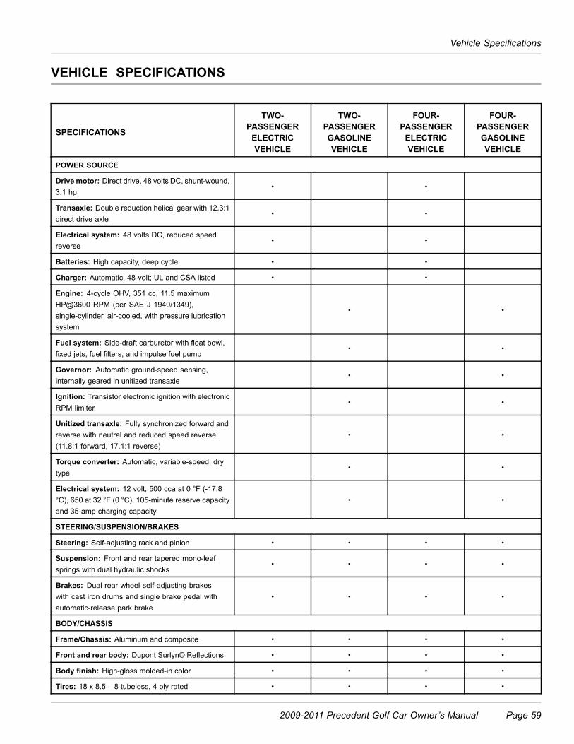
Vehicle Specifications
VEHICLE SPECIFICATIONS
SPECIFICATIONS
TWO-PASSENGERELECTRICVEHICLE
TWO-PASSENGERGASOLINEVEHICLE
FOUR-PASSENGERELECTRICVEHICLE
FOUR-PASSENGERGASOLINEVEHICLE
POWER SOURCE
Drive motor: Direct drive, 48 volts DC, shunt-wound,3.1 hp
• •
Transaxle: Double reduction helical gear with 12.3:1direct drive axle
• •
Electrical system: 48 volts DC, reduced speedreverse
• •
Batteries: High capacity, deep cycle • •
Charger: Automatic, 48-volt; UL and CSA listed • •
Engine: 4-cycle OHV, 351 cc, 11.5 maximumHP@3600 RPM (per SAE J 1940/1349),single-cylinder, air-cooled, with pressure lubricationsystem
• •
Fuel system: Side-draft carburetor with float bowl,fixed jets, fuel filters, and impulse fuel pump
• •
Governor: Automatic ground-speed sensing,internally geared in unitized transaxle
• •
Ignition: Transistor electronic ignition with electronicRPM limiter
• •
Unitized transaxle: Fully synchronized forward andreverse with neutral and reduced speed reverse(11.8:1 forward, 17.1:1 reverse)
• •
Torque converter: Automatic, variable-speed, drytype
• •
Electrical system: 12 volt, 500 cca at 0 °F (-17.8°C), 650 at 32 °F (0 °C). 105-minute reserve capacityand 35-amp charging capacity
• •
STEERING/SUSPENSION/BRAKES
Steering: Self-adjusting rack and pinion • • • •
Suspension: Front and rear tapered mono-leafsprings with dual hydraulic shocks
• • • •
Brakes: Dual rear wheel self-adjusting brakeswith cast iron drums and single brake pedal withautomatic-release park brake
• • • •
BODY/CHASSIS
Frame/Chassis: Aluminum and composite • • • •
Front and rear body: Dupont Surlyn© Reflections • • • •
Body finish: High-gloss molded-in color • • • •
Tires: 18 x 8.5 – 8 tubeless, 4 ply rated • • • •
2009-2011 Precedent Golf Car Owner’s Manual Page 59
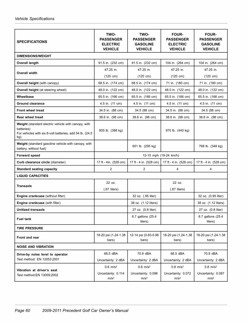
Vehicle Specifications
SPECIFICATIONS
TWO-PASSENGERELECTRICVEHICLE
TWO-PASSENGERGASOLINEVEHICLE
FOUR-PASSENGERELECTRICVEHICLE
FOUR-PASSENGERGASOLINEVEHICLE
DIMENSIONS/WEIGHT
Overall length 91.5 in. (232 cm) 91.5 in. (232 cm) 104 in. (264 cm) 104 in. (264 cm)
Overall width47.25 in.
(120 cm)
47.25 in.
(120 cm)
47.25 in.
(120 cm)
47.25 in.
(120 cm)
Overall height (with canopy) 68.5 in. (174 cm) 68.5 in. (174 cm) 71 in. (180 cm) 71 in. (180 cm)
Overall height (at steering wheel) 48.0 in. (122 cm) 48.0 in. (122 cm) 48.0 in. (122 cm) 48.0 in. (122 cm)
Wheelbase 65.5 in. (166 cm) 65.5 in. (166 cm) 65.5 in. (166 cm) 65.5 in. (166 cm)
Ground clearance 4.5 in. (11 cm) 4.5 in. (11 cm) 4.5 in. (11 cm) 4.5 in. (11 cm)
Front wheel tread 34.5 in. (88 cm) 34.5 (88 cm) 34.5 in. (88 cm) 34.5 (88 cm)
Rear wheel tread 38.6 in. (98 cm) 38.6 in. (98 cm) 38.6 in. (98 cm) 38.6 in. (98 cm)
Weight (standard electric vehicle with canopy, withbatteries)For vehicles with six 8-volt batteries, add 54 lb. (24.5kg).
855 lb. (388 kg) 970 lb. (440 kg)
Weight (standard gasoline vehicle with canopy, withbattery, without fuel)
651 lb. (295 kg) 768 lb. (348 kg)
Forward speed 12-15 mph (19-24 km/h)
Curb clearance circle (diameter) 17 ft - 4in. (528 cm) 17 ft - 4 in. (528 cm) 17 ft - 4 in. (528 cm) 17 ft - 4 in. (528 cm)
Standard seating capacity 2 2 4 4
LIQUID CAPACITIES
Transaxle22 oz.
(.67 liters)
22 oz.
(.67 liters)
Engine crankcase (without filter) 32 oz. (.95 liter) 32 oz. (0.95 liter)
Engine crankcase (with filter) 38 oz. (1.12 liters) 38 oz. (1.12 liters)
Unitized transaxle 27 oz. (0.8 liter) 27 oz. (0.8 liter)
Fuel tank6.7 gallons (25.4
liters)6.7 gallons (25.4
liters)
TIRE PRESSURE
Front and rear18-20 psi (1.24-1.38
bars)12-14 psi (0.83-0.96
bars)18-20 psi (1.24-1.38
bars)18-20 psi (1.24-1.38
bars)
NOISE AND VIBRATION
Drive-by noise level to operatorTest method: EN 12053:2001
68.5 dBA
Uncertainty: 2 dBA
70.9 dBA
Uncertainty: 2 dBA
68.5 dBA
Uncertainty: 2 dBA
70.9 dBA
Uncertainty: 2 dBA
Vibration at driver’s seatTest method:EN 13059:2002
0.6 m/s2
Uncertainty: 0.114m/s2
0.8 m/s2
Uncertainty: 0.096m/s2
0.8 m/s2
Uncertainty: 0.072m/s2
0.8 m/s2
Uncertainty: 0.087m/s2
Page 60 2009-2011 Precedent Golf Car Owner’s Manual
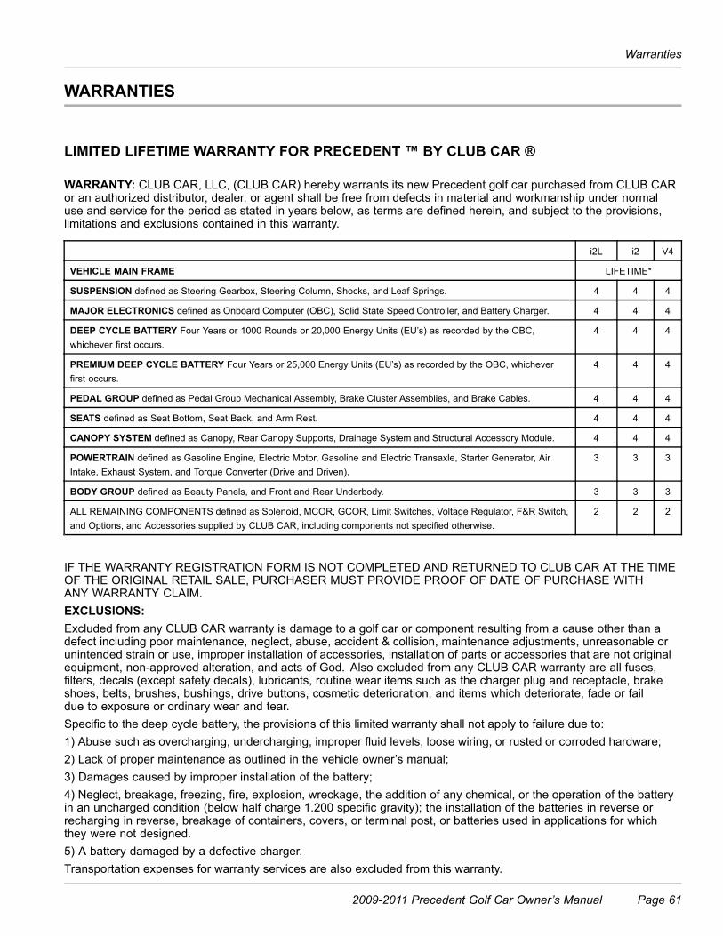
Warranties
WARRANTIES
LIMITED LIFETIME WARRANTY FOR PRECEDENT ™ BY CLUB CAR ®
WARRANTY: CLUB CAR, LLC, (CLUB CAR) hereby warrants its new Precedent golf car purchased from CLUB CARor an authorized distributor, dealer, or agent shall be free from defects in material and workmanship under normaluse and service for the period as stated in years below, as terms are defined herein, and subject to the provisions,limitations and exclusions contained in this warranty.
i2L i2 V4
VEHICLE MAIN FRAME LIFETIME*
SUSPENSION defined as Steering Gearbox, Steering Column, Shocks, and Leaf Springs. 4 4 4
MAJOR ELECTRONICS defined as Onboard Computer (OBC), Solid State Speed Controller, and Battery Charger. 4 4 4
DEEP CYCLE BATTERY Four Years or 1000 Rounds or 20,000 Energy Units (EU’s) as recorded by the OBC,whichever first occurs.
4 4 4
PREMIUM DEEP CYCLE BATTERY Four Years or 25,000 Energy Units (EU’s) as recorded by the OBC, whicheverfirst occurs.
4 4 4
PEDAL GROUP defined as Pedal Group Mechanical Assembly, Brake Cluster Assemblies, and Brake Cables. 4 4 4
SEATS defined as Seat Bottom, Seat Back, and Arm Rest. 4 4 4
CANOPY SYSTEM defined as Canopy, Rear Canopy Supports, Drainage System and Structural Accessory Module. 4 4 4
POWERTRAIN defined as Gasoline Engine, Electric Motor, Gasoline and Electric Transaxle, Starter Generator, AirIntake, Exhaust System, and Torque Converter (Drive and Driven).
3 3 3
BODY GROUP defined as Beauty Panels, and Front and Rear Underbody. 3 3 3
ALL REMAINING COMPONENTS defined as Solenoid, MCOR, GCOR, Limit Switches, Voltage Regulator, F&R Switch,and Options, and Accessories supplied by CLUB CAR, including components not specified otherwise.
2 2 2
IF THE WARRANTY REGISTRATION FORM IS NOT COMPLETED AND RETURNED TO CLUB CAR AT THE TIMEOF THE ORIGINAL RETAIL SALE, PURCHASER MUST PROVIDE PROOF OF DATE OF PURCHASE WITHANY WARRANTY CLAIM.EXCLUSIONS:Excluded from any CLUB CAR warranty is damage to a golf car or component resulting from a cause other than adefect including poor maintenance, neglect, abuse, accident & collision, maintenance adjustments, unreasonable orunintended strain or use, improper installation of accessories, installation of parts or accessories that are not originalequipment, non-approved alteration, and acts of God. Also excluded from any CLUB CAR warranty are all fuses,filters, decals (except safety decals), lubricants, routine wear items such as the charger plug and receptacle, brakeshoes, belts, brushes, bushings, drive buttons, cosmetic deterioration, and items which deteriorate, fade or faildue to exposure or ordinary wear and tear.Specific to the deep cycle battery, the provisions of this limited warranty shall not apply to failure due to:1) Abuse such as overcharging, undercharging, improper fluid levels, loose wiring, or rusted or corroded hardware;2) Lack of proper maintenance as outlined in the vehicle owner’s manual;3) Damages caused by improper installation of the battery;4) Neglect, breakage, freezing, fire, explosion, wreckage, the addition of any chemical, or the operation of the batteryin an uncharged condition (below half charge 1.200 specific gravity); the installation of the batteries in reverse orrecharging in reverse, breakage of containers, covers, or terminal post, or batteries used in applications for whichthey were not designed.5) A battery damaged by a defective charger.Transportation expenses for warranty services are also excluded from this warranty.
2009-2011 Precedent Golf Car Owner’s Manual Page 61

Warranties
VOIDING OF WARRANTY:THIS AND ANY OTHER WARRANTY SHALL BE VOID IF THE GOLF CAR IS ABUSED OR USED IN ANUNINTENDED MANNER OR SHOWS INDICATIONS THAT IT HAS BEEN ALTERED IN ANY WAY, INCLUDING,BUT NOT LIMITED TO, MODIFICATION OF THE SPEED GOVERNOR, BRAKING SYSTEM, STEERING,TRANSAXLE, OR OTHER OPERATING SYSTEMS OF THE CAR TO CAUSE IT TO PERFORM OUTSIDE CLUB CARSPECIFICATIONS. THE WARRANTY IS LIKEWISE VOID IF THE CAR INVOLVED SHOWS INDICATIONS THATREASONABLE OR NECESSARY MAINTENANCE AS OUTLINED IN THE OWNER’S MANUAL AND MAINTENANCEAND SERVICE MANUAL WAS NOT PERFORMED AT THE TIME AND IN THE MANNER SPECIFIED IN SUCHMANUALS.SOLE REMEDY:CLUB CAR’s liability under this limited warranty, or in any action whether based upon warranty, contract, negligence,strict product liability or otherwise, shall be the repair or replacement, at CLUB CAR’s option, of the golf car orcomponent thereof that CLUB CAR deems to be defective. Replacement shall mean furnishing, during the applicablelimited warranty period, a new golf car or factory-reconditioned vehicle or component thereof that is identical orreasonably equivalent to the warranted product or component at no cost to the purchaser. Repair shall meanremedying a defect in the golf car or component thereof at no cost to the purchaser during the applicable limitedwarranty period. If CLUB CAR elects to repair the golf car, it may provide factory-reconditioned parts or components.All parts and components replaced under warranty shall become the property of CLUB CAR.DISCLAIMER:THIS LIMITED WARRANTY IS EXCLUSIVE. CLUB CAR MAKES NO OTHER WARRANTY OF ANY KIND,EXPRESSED OR IMPLIED. ANY IMPLIED WARRANTIES OF MERCHANTABILITY OR FITNESS FOR APARTICULAR PURPOSE WHICH EXCEED THE OBLIGATIONS OR TIME LIMITS STATED IN THIS WARRANTYARE HEREBY DISCLAIMED BY CLUB CAR AND EXCLUDED FROM THIS WARRANTY. THE PURCHASER ANDCLUB CAR EXPRESSLY AGREE THAT THE SOLE REMEDY OF THE REPLACEMENT OR REPAIR OF THEDEFECTIVE GOLF CAR OR COMPONENT THEREOF IS THE SOLE REMEDY OF THE PURCHASER. CLUBCAR MAKES NO OTHER REPRESENTATION OR WARRANTY OF ANY KIND, AND NO REPRESENTATIVE,EMPLOYEE, DISTRIBUTOR OR DEALER OF CLUB CAR HAS THE AUTHORITY TO MAKE OR IMPLY ANYREPRESENTATION, PROMISE OR AGREEMENT, WHICH IN ANY WAY VARIES THE TERMS OF THISWARRANTY.In the event that another pre-printed warranty document and/or certificate offered by or through Club Car at the time ofsale of this vehicle (each an “Additional Warranty Document”) is deemed to conflict with the limitations or exclusionscontained herein, the limitations and exclusions contained herein shall continue to apply with respect to both this limitedwarranty statement and, to the maximum extent permitted by law, to each Additional Warranty Document.NO CONSEQUENTIAL DAMAGES:IN NO EVENT SHALL CLUB CAR BE LIABLE FOR ANY INCIDENTAL OR CONSEQUENTIAL DAMAGESINCLUDING, BUT NOT LIMITED TO, LOSS RELATED TO PROPERTY OTHER THAN THE GOLF CAR, LOSS OFUSE, LOSS OF TIME, INCONVENIENCE, OR ANY OTHER ECONOMIC LOSS.Some states allow neither limitation on the duration of an implied warranty nor exclusions or limitation of incidental orconsequential damages. Therefore, the above limitations or exclusions may not apply to you.This warranty gives you specific legal rights, and you may also have other rights, which vary from state to state.INFORMATION:For further information contact WARRANTY SERVICES, CLUB CAR, LLC, P.O. Box 204658, Augusta, Georgia30917-4658, U.S.A., 706-863-3000.WARRANTY TRANSFER:The original owner shall have the right to transfer any remaining warranty coverage to one subsequent purchaser only.In order for the original owner to transfer any remaining warranty coverage to a subsequent purchaser, the vehicle mustbe re-registered by an Authorized Club Car Distributor or Dealer with the Warranty Department at Club Car, LLC. Suchtransfer must take place within the first three years of the original in service date of the vehicle. *The Limited Lifetimesection of the warranty coverage applies to the original purchaser or lessee only, and the subsequent purchaser willonly have a four-year coverage period based on the original in service date. No transfers of any remaining warrantycoverage shall be permitted by any subsequent purchasers.WARNING:Any modification or alteration of any golf car beyond factory specifications, including those that affect the weightdistribution, stability, or speed of the golf car, can cause serious personal injury or death.
Page 62 2009-2011 Precedent Golf Car Owner’s Manual

Warranties
CALIFORNIA EMISSION CONTROL WARRANTY STATEMENT
YOUR WARRANTY RIGHTS AND OBLIGATIONS:The California Air Resources Board (“CARB”) and Club Car, LLC (“CLUB CAR”) are pleased to explain the emissioncontrol system warranty on your 2009 and newer vehicle engine (the “emission warranty”). In California, new smalloff-road engines (“SORE”) must be designed, built and equipped to meet the State’s stringent anti-smog standards.CLUB CAR shall warrant the emission control system on the vehicle engine for the periods of time listed belowprovided there has been no abuse, neglect or improper maintenance of your small off-road engine.Your emission control system may include parts such as the carburetor or fuel-injection system, the ignition system, thecatalytic converter and related hoses, belts, connectors and other emission assemblies or components.Where a warrantable condition exists, as defined herein, CLUB CAR will repair your vehicle engine at no cost toyou including diagnosis, parts and labor.MANUFACTURER’S WARRANTY COVERAGE:This emission control system is warranted for two years from the vehicles’ date of purchase. If any emission-relatedpart on your CLUB CAR SORE is defective, the part will be repaired or replaced by CLUB CAR.OWNER’S WARRANTY RESPONSIBILITIES:- As the vehicle engine owner, you are responsible for the performance of the required maintenance listed in yourowner’s manual. CLUB CAR recommends that you retain all receipts covering maintenance on your vehicle engine,but CLUB CAR cannot deny warranty solely for the lack of receipts or for your failure to ensure the performance of allscheduled maintenance.- As the vehicle engine owner, you should however be aware that CLUB CAR may deny you warranty coverage ifvehicle engine or a part has failed due to abuse, neglect, improper maintenance or unapproved modifications.- You are responsible for presenting vehicle engine to a CLUB CAR distribution center as soon as a problem exists.The warranty repairs should be completed in a reasonable amount of time, not to exceed 30 days. If you have anyquestions regarding your warranty rights and responsibilities, you should contact WARRANTY SERVICES, CLUBCAR, LLC, P.O. Box 204658, Augusta, Georgia 30917-4658, U.S.A., 1-706-863-3000.CLUB CAR EXPLANATION OF EMISSION CONTROL WARRANTY:1. WARRANTY:CLUB CAR warrants to the ultimate purchaser and each subsequent purchaser that the SORE and related emissionsequipment is designed, built and equipped so as to conform with all applicable California environmental emissionregulations; and free from defects in materials and workmanship that cause the failure of a warranted part to beidentical in all material respects to that part as described in CLUB CAR’s application for certification with CARB. Thewarranty period begins on the date the engine or equipment is delivered to an ultimate purchaser or first placed intoservice. The warranty period is two years from the date of purchase.2. COVERAGE:Subject to certain conditions and exclusions as stated below, the warranty on emission-related parts is as follows:(1) Any warranted part that is not scheduled for replacement as required maintenance in the written instructionssupplied, is warranted for the warranty period stated above. If the part fails during the period of warranty coverage, thepart will be repaired or replaced by CLUB CAR according to subsection (4) below. Any such part repaired or replacedunder warranty will be warranted for the remainder of the original warranty period.(2) Any warranted part that is scheduled only for regular inspection in the written instructions supplied is warrantedfor the warranty period stated above. Any such part repaired or replaced under warranty will be warranted for theremaining original warranty period.(3) Any warranted part that is scheduled for replacement as required maintenance in the written instructions supplied iswarranted for the period of time before the first scheduled replacement date for that part. If the part fails before thefirst scheduled replacement, the part will be repaired or replaced by CLUB CAR according to subsection (4) below.Any such part repaired or replaced under warranty will be warranted for the remainder of the period prior to the firstscheduled replacement point for the part.(4) Repair or replacement of any warranted part under the warranty provisions herein must be performed at a warrantystation* at no charge to the owner.(5) Notwithstanding the provisions herein, warranty services or repairs will be provided at all of our distribution centersthat are franchised to service the subject engines or equipment.
2009-2011 Precedent Golf Car Owner’s Manual Page 63

Warranties
(6) The engine or equipment owner will not be charged for diagnostic labor that is directly associated with diagnosis ofa defective, emission-related warranted part, provided that such diagnostic work is performed at a warranty station*.(7) CLUB CAR is liable for damages to other engine or equipment components proximately caused by a coveredfailure under warranty of any warranted part.(8) Throughout the engine or equipment warranty period stated above, CLUB CAR will maintain a supply of warrantedparts sufficient to meet the expected demand for such parts.(9) Any replacement part may be used in the performance of any warranty maintenance or repairs and must beprovided without charge to the owner. Such use will not reduce the warranty obligations of CLUB CAR.(10) Add-on or modified parts that are not exempted by the Air Resources Board may not be used. The use of anynon-exempted add-on or modified parts by the ultimate purchaser will be grounds for disallowing a warranty claims.CLUB CAR will not be liable to warrant failures of warranted parts caused by the use of a non-exempted add-on ormodified part.*CLUB CAR, its authorized dealers, or a service agency approved by CLUB CAR.ITEMS COVERED BY THIS WARRANTY:The repair or replacement of any warranted part otherwise eligible for warranty coverage may be excluded fromsuch warranty coverage if CLUB CAR demonstrates that the engine or equipment has been abused, neglected, orimproperly maintained, and that such abuse, neglect, or improper maintenance was the direct cause of the need forrepair or replacement of the part. That notwithstanding, any adjustment of a component that has a factory installed,and properly operating, adjustment limiting device is still eligible for warranty coverage. The following emissionwarranty parts list are covered:SYSTEMS COVERED PARTS DESCRIPTIONFuel Metering Carburetor assembly, fuel injection pump, fuel injection nozzle, fuel regulator Exhaust CatalyticConverter, Exhaust Manifold Air Induction Air filter housing, air filter*, crankcase breather tube Ignition Flywheelmagneto, ignition pulse generator, ignition coil assembly, ignition control module, spark plug cap, spark plug* PositiveCrankcase Ventilation (PCV) System PCV valve, oil filler cap Evaporative System Fuel Tank, Fuel Cap, Fuel Lines,Fuel Line Fittings, Clamps, Pressure Relief Valves, Purge Valves, Vapor Hoses, Carbon Canister, Canister MountingBrackets, Carbon Canister Purge Port Connector Misc. Parts Belts, hosing, tubing, fittings, seals, gaskets, clamps, andswitches associated with the above systems.Emission-related parts will vary between vehicles; therefore, certain vehicles may not include all of the listed partsor may include equivalent parts.3. VOIDING OF WARRANTY:THIS AND ANY OTHER WARRANTY SHALL BE VOID IF THE VEHICLE IS ABUSED OR USED IN AN UNINTENDEDMANNER OR SHOWS INDICATIONS THAT IT HAS BEEN ALTERED IN ANY WAY, INCLUDING, BUT NOT LIMITEDTO, MODIFICATION OF THE SPEED GOVERNOR, BRAKING SYSTEM, STEERING, TRANSAXLE, OR OTHEROPERATING SYSTEMS OF THE VEHICLE TO CAUSE IT TO PERFORM OUTSIDE CLUB CAR SPECIFICATIONS.4. HOW TO MAKE A WARRANTY CLAIM:To make a warranty claim under this limited warranty, you must present the vehicle or defective component to anauthorized CLUB CAR dealer or send the defective component, freight prepaid, to WARRANTY SERVICES, CLUBCAR, LLC, 4125 Washington Road, Evans, Georgia 30809, U.S.A., 706-863-3000.
Page 64 2009-2011 Precedent Golf Car Owner’s Manual

EC Declaration of Conformity
EC DECLARATION OF CONFORMITY
When properly configured, the vehicle complies with the listed Directives.
2009-2011 Precedent Golf Car Owner’s Manual Page 65
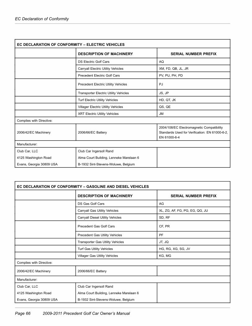
EC Declaration of Conformity
EC DECLARATION OF CONFORMITY – ELECTRIC VEHICLES
DESCRIPTION OF MACHINERY SERIAL NUMBER PREFIX
DS Electric Golf Cars AQ
Carryall Electric Utility Vehicles XM, FD, QB, JL, JR
Precedent Electric Golf Cars PV, PU, PH, PD
Precedent Electric Utility Vehicles PJ
Transporter Electric Utility Vehicles JS, JP
Turf Electric Utility Vehicles HD, QT, JK
Villager Electric Utility Vehicles QS, QE
XRT Electric Utility Vehicles JM
Complies with Directive:
2006/42/EC Machinery 2006/66/EC Battery2004/108/EC Electromagnetic CompatibilityStandards Used for Verification: EN 61000-6-2,EN 61000-6-4
Manufacturer:
Club Car, LLC
4125 Washington Road
Evans, Georgia 30809 USA
Club Car Ingersoll Rand
Alma Court Building, Lenneke Marelaan 6
B-1932 Sint-Stevens-Woluwe, Belgium
EC DECLARATION OF CONFORMITY – GASOLINE AND DIESEL VEHICLES
DESCRIPTION OF MACHINERY SERIAL NUMBER PREFIX
DS Gas Golf Cars AG
Carryall Gas Utility Vehicles XL, ZG, AF, FG, PG, EG, QG, JU
Carryall Diesel Utility Vehicles SD, RF
Precedent Gas Golf Cars CF, PR
Precedent Gas Utility Vehicles PF
Transporter Gas Utility Vehicles JT, JQ
Turf Gas Utility Vehicles HG, RG, XG, SG, JV
Villager Gas Utility Vehicles KG, MG
Complies with Directive:
2006/42/EC Machinery 2006/66/EC Battery
Manufacturer:
Club Car, LLC
4125 Washington Road
Evans, Georgia 30809 USA
Club Car Ingersoll Rand
Alma Court Building, Lenneke Marelaan 6
B-1932 Sint-Stevens-Woluwe, Belgium
Page 66 2009-2011 Precedent Golf Car Owner’s Manual

EC Declaration of Conformity
Re gis te red ISO 9001-2008
Declara tion of Co nformity
Model Cod e
Model Number
Model Name
PH 103399101 Precedent i2 Excel PD 103399201 Precedent i2L Excel PJ 103399301 Precedent i2 4 Passenger Excel PU 103399501 Precedent i2 Signature PV 103399601 Precedent i2 4 Passenger Signature
Ser ia l numbers 1101000001 and grea te r Four whee l e lec tric vehicles in the above se ries which bear the CE mark fulfill a ll the re levant provis ions of the following Direc tives Enspricht den Bes timmungen, Conforme Aux Directives , Conforme Con Las Directivas , Voldoet aan Richtlijnen, De Acordo com Directiva , Conforme Alla Dire ttiva , Opfylder folgende direktiver, Upptylle r foljande direktiv
2006/42/EC Mac hinery 2006/66/EC Bat teries and Accum ulators and Waste Batte ries and Accumula tors 2004/108/EC Elec troma gnetic Compa tibility
S tandards us ed for ver ifica tion Standards fur Uberprufung, S tandard Utilis ee pour Verifica tion, Normas Usado por Comprobacion, Waarden Aangewend voor Verifica tie , Modelos Utilizado para Verifcacao, S tandard per la Verifica , S tandarder Anvendte Nemlig Efte rprovning, S tandarden Anvand for Bekraftanden
EN 61000-6-2 EN 61000-6-4
Manufac turer Hers te lle r, Fa bricant, Fa bricante , Fa brikant, Fa bricante , Fa bbricante , P roducent, Tillverkare
Club Car , LLC 4125 Was hington Road Evans , Georgia 308 09 USA
Authorized repres enta tive and pe rso n authorized to compile the technica l file Autoris ierte r Händler, Representant Duement Acrédité , Representante Autorizado, Wettige Vertegenwoordiging, Representa te Autorizado, Rappresentante Autorizza to, Autoriscre t repræ sentant, Auktoriserad representant:
Club Car Ingerso ll Rand Alma Court Building Lenneke Mare laan 6 B-1932 Sint-Stevens-Woluwe, Be lgium
_______________________________________________ Geoff S tewar t Augus t 2, 2010 Lead Engineer , Product Safe ty Evans , Georgia , USA
2009-2011 Precedent Golf Car Owner’s Manual Page 67

EC Declaration of Conformity
Re gis te red ISO 9001-2008 H:\ECS\ELEC CE CERT 2011.DOC
Dec la ra tion of Co nformity
Model Code
Model Number
Model Name
PR 102537101 Precedent i2 Gas CF 102537201 Precedent i2L Gas PF 102537401 Precedent i2 4 Passenger Gas PY 103228901 Precedent i2 Signature Gas PX 103229101 Precedent i2 4 Passenger Signature
Seria l numbers 1101000001 and grea te r Four-whee l gas oline vehicles in the above se ries tha t bear the CE mark fulfill a ll the re levant provis ions of the following Direc tives Enspricht den Bes timmungen, Conforme Aux Directives , Conforme Con Las Directivas , Voldoet aan Richtlijnen, De Acordo com Directiva , Conforme Alla Dire ttiva , Opfylder folgende direktiver, Upptylle r foljande direktiv
2006/42/EC Mac hinery 2006/66/EC Batter ies and Accumu lators and Waste Batte ries and Accumula tors
S tandards us ed for verifica tion Standards fur Uberprufung, S tandard Utilis ee pour Verifica tion, Normas Usado por Comprobacion, Waarden Aangewend voor Verifica tie , Modelos Utilizado para Verifcacao, S tandard per la Verifica , S tandarder Anvendte Nemlig Efte rprovning, S tandarden Anvand for Bekraftanden
N/A
Manufac turer Hers te lle r, Fa bricant, Fa bricante , Fa brikant, Fa bricante , Fa bbricante , P roducent, Tillverkare
Club Car , LLC 4125 Was hington Road Evans , Georgia 30809 USA
Autho rized repres enta tive and pe rson authorized to compile the technica l file Autoris ierte r Händler, Representant Duement Acrédité , Representante Autorizado, Wettige Vertegenwoordiging, Representa te Autorizado, Rappresentante Autorizza to, Autoriscre t repræ sentant, Auktoriserad representant:
Club Car Ingersoll Rand Alma Court Building Lenneke Mare laan 6 B-1932 Sint-Stevens-Woluwe, Be lgium
_______________________________________________ Geoff S tewart November 2, 2010 Lead Engineer , Product Safe ty Evans , Georgia , USA
Page 68 2009-2011 Precedent Golf Car Owner’s Manual


Publication Part Number 103472529
Edition Code 1108U0411T
103472529


