2007 Hummer H3 2007 STEERING Power Steering - H3...Power Steering System Test Step Action Value(s)...
67
2007 STEERING Power Steering - H3 SPECIFICATIONS FASTENER TIGHTENING SPECIFICATIONS Fastener Tightening Specifications POWER STEERING PUMP SPECIFICATIONS Power Steering Pump Specifications DIAGNOSTIC INFORMATION AND PROCEDURES DIAGNOSTIC STARTING POINT - POWER STEERING SYSTEM Begin the system diagnosis by reviewing the system Description and Operation. Refer to Power Steering System Description and Operation . Reviewing the Description and Operation information will help you determine the correct symptom diagnostic procedure when a malfunction exists. Reviewing the Description and Operation information will also help you Application Specification Metric English Power Steering Gear Inlet and Outlet Hose Retaining Plate Bolt 12 N.m 106 lb in Power Steering Gear Inlet and Outlet Hose Bracket Bolt 9 N.m 80 lb in Power Steering Gear Inlet Hose Fitting 25 N.m 18 lb ft Power Steering Pump Bolt 25 N.m 18 lb ft Power Steering Pump Bracket Bolt 50 N.m 37 lb ft Rack and Pinion Inner Tie Rod 88 N.m 65 lb ft Rack and Pinion Outer Tie Rod End Nut 71 N.m 52 lb ft Steering Gear Bolt 130 N.m 96 lb ft Steering Gear Bracket Bolt 100 N.m 74 lb ft Engine Code Engine Size High Flow (Liters per Minute) High Flow (Gallons per Minute) Pressure Relief (kPa) Pressure Relief (PSI) L52 3.5L 9.4/10.9 2.50/2.90 9308/9997 1350/1450 2007 Hummer H3 2007 STEERING Power Steering - H3 2007 Hummer H3 2007 STEERING Power Steering - H3
Transcript of 2007 Hummer H3 2007 STEERING Power Steering - H3...Power Steering System Test Step Action Value(s)...
2007 STEERING
Power Steering - H3
SPECIFICATIONS
FASTENER TIGHTENING SPECIFICATIONS
Fastener Tightening Specifications
POWER STEERING PUMP SPECIFICATIONS
Power Steering Pump Specifications
DIAGNOSTIC INFORMATION AND PROCEDURES
DIAGNOSTIC STARTING POINT - POWER STEERING SYSTEM
Begin the system diagnosis by reviewing the system Description and Operation. Refer to Power Steering System Description and Operation. Reviewing the Description and Operation information will help you determine the correct symptom diagnostic procedure when a malfunction exists. Reviewing the Description and Operation information will also help you
ApplicationSpecification
Metric EnglishPower Steering Gear Inlet and Outlet Hose Retaining Plate Bolt
12 N.m 106 lb in
Power Steering Gear Inlet and Outlet Hose Bracket Bolt
9 N.m 80 lb in
Power Steering Gear Inlet Hose Fitting 25 N.m 18 lb ftPower Steering Pump Bolt 25 N.m 18 lb ftPower Steering Pump Bracket Bolt 50 N.m 37 lb ftRack and Pinion Inner Tie Rod 88 N.m 65 lb ftRack and Pinion Outer Tie Rod End Nut 71 N.m 52 lb ftSteering Gear Bolt 130 N.m 96 lb ftSteering Gear Bracket Bolt 100 N.m 74 lb ft
Engine Code Engine Size
High Flow (Liters per
Minute)
High Flow (Gallons per
Minute)Pressure
Relief (kPa)Pressure
Relief (PSI)L52 3.5L 9.4/10.9 2.50/2.90 9308/9997 1350/1450
2007 Hummer H3
2007 STEERING Power Steering - H3
2007 Hummer H3
2007 STEERING Power Steering - H3
MY
Sunday, March 29, 2009 9:33:34 PM Page 1 © 2005 Mitchell Repair Information Company, LLC.
MY
Sunday, March 29, 2009 9:33:38 PM Page 1 © 2005 Mitchell Repair Information Company, LLC.
determine if the condition described by the customer is normal operation. Refer to Symptoms - Power Steering System in order to identify the correct procedure for diagnosing the system and where the procedure is located.
SYMPTOMS - POWER STEERING SYSTEM
Visual/Physical Inspection
� Inspect for aftermarket devices which could affect the operation of the power steering system.
� Inspect the easily accessible or visible system components for obvious damage or conditions which could cause the symptom.
� Inspect for leaking power steering components. If necessary, refer to Power Steering Fluid Leaks.
� Verify the power steering reservoir for the proper operating specification. Refer to Checking and Adding Power Steering Fluid.
� Inspect the power steering fluid for the following indications of contamination: � Milky fluid - water � Brown fluid - burnt � Debris in fluid - plastic or dirt
� If necessary, flush the power steering system. Refer to Power Steering System Flushing.
Symptoms List
Refer to a symptom diagnostic procedure from the following list in order to diagnose the symptom:
� Power Steering Fluid Leaks � Rattle, Clunk or Shudder Noise from the Power Steering System
� Whine or Growl Noise from the Power Steering System
� Steering Effort Hard in One or Both Directions � Steering Effort Too Easy in One or Both Directions
POWER STEERING SYSTEM TEST
IMPORTANT: Review the system description and operation in order to familiarize yourself with the system functions. Refer to Power Steering System Description and Operation.
2007 Hummer H3
2007 STEERING Power Steering - H3
MY
Sunday, March 29, 2009 9:33:34 PM Page 2 © 2005 Mitchell Repair Information Company, LLC.
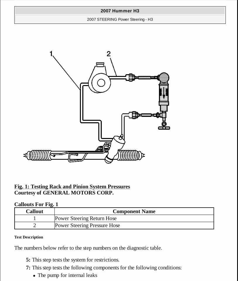
Fig. 1: Testing Rack and Pinion System Pressures Courtesy of GENERAL MOTORS CORP.
Callouts For Fig. 1
Test Description
The numbers below refer to the step numbers on the diagnostic table.
5: This step tests the system for restrictions.
7: This step tests the following components for the following conditions: � The pump for internal leaks
Callout Component Name1 Power Steering Return Hose2 Power Steering Pressure Hose
2007 Hummer H3
2007 STEERING Power Steering - H3
MY
Sunday, March 29, 2009 9:33:34 PM Page 3 © 2005 Mitchell Repair Information Company, LLC.
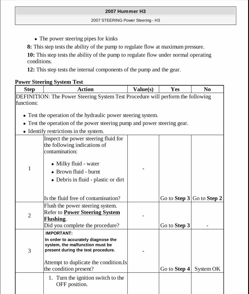
� The power steering pipes for kinks
8: This step tests the ability of the pump to regulate flow at maximum pressure.
10: This step tests the ability of the pump to regulate flow under normal operating conditions.
12: This step tests the internal components of the pump and the gear.
Power Steering System Test Step Action Value(s) Yes No
DEFINITION: The Power Steering System Test Procedure will perform the following functions:
� Test the operation of the hydraulic power steering system. � Test the operation of the power steering pump and power steering gear. � Identify restrictions in the system.
1
Inspect the power steering fluid for the following indications of contamination:
� Milky fluid - water � Brown fluid - burnt � Debris in fluid - plastic or dirt
Is the fluid free of contamination?
-
Go to Step 3 Go to Step 2
2
Flush the power steering system. Refer to Power Steering System Flushing. Did you complete the procedure?
-
Go to Step 3 -
3
Attempt to duplicate the condition.Is the condition present?
IMPORTANT:
In order to accurately diagnose the system, the malfunction must be present during the test procedure. -
Go to Step 4 System OK
1. Turn the ignition switch to the OFF position.
2007 Hummer H3
2007 STEERING Power Steering - H3
MY
Sunday, March 29, 2009 9:33:34 PM Page 4 © 2005 Mitchell Repair Information Company, LLC.
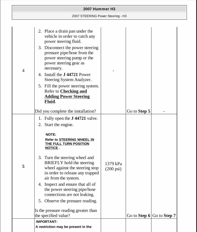
4
2. Place a drain pan under the vehicle in order to catch any power steering fluid.
3. Disconnect the power steering pressure pipe/hose from the power steering pump or the power steering gear as necessary.
4. Install the J 44721 Power Steering System Analyzer.
5. Fill the power steering system. Refer to Checking and Adding Power Steering Fluid.
Did you complete the installation?
-
Go to Step 5 -
5
1. Fully open the J 44721 valve. 2. Start the engine.
3. Turn the steering wheel and BRIEFLY hold the steering wheel against the steering stop in order to release any trapped air from the system.
4. Inspect and ensure that all of the power steering pipe/hose connections are not leaking.
5. Observe the pressure reading.
Is the pressure reading greater than the specified value?
NOTE:
Refer to STEERING WHEEL IN THE FULL TURN POSITION NOTICE .
1379 kPa (200 psi)
Go to Step 6 Go to Step 7 IMPORTANT:
A restriction may be present in the
2007 Hummer H3
2007 STEERING Power Steering - H3
MY
Sunday, March 29, 2009 9:33:34 PM Page 5 © 2005 Mitchell Repair Information Company, LLC.
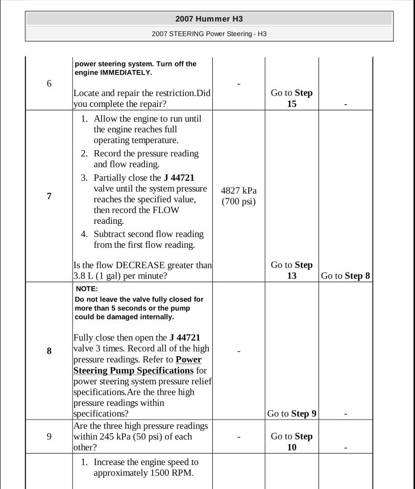
6Locate and repair the restriction.Did you complete the repair?
power steering system. Turn off the engine IMMEDIATELY.
-Go to Step
15 -
7
1. Allow the engine to run until the engine reaches full operating temperature.
2. Record the pressure reading and flow reading.
3. Partially close the J 44721 valve until the system pressure reaches the specified value, then record the FLOW reading.
4. Subtract second flow reading from the first flow reading.
Is the flow DECREASE greater than 3.8 L (1 gal) per minute?
4827 kPa (700 psi)
Go to Step 13 Go to Step 8
8 Fully close then open the J 44721 valve 3 times. Record all of the high pressure readings. Refer to Power Steering Pump Specifications for power steering system pressure relief specifications.Are the three high pressure readings within specifications?
NOTE:Do not leave the valve fully closed for more than 5 seconds or the pump could be damaged internally.
-
Go to Step 9 -
9Are the three high pressure readings within 245 kPa (50 psi) of each other?
- Go to Step 10 -
1. Increase the engine speed to approximately 1500 RPM.
2007 Hummer H3
2007 STEERING Power Steering - H3
MY
Sunday, March 29, 2009 9:33:34 PM Page 6 © 2005 Mitchell Repair Information Company, LLC.
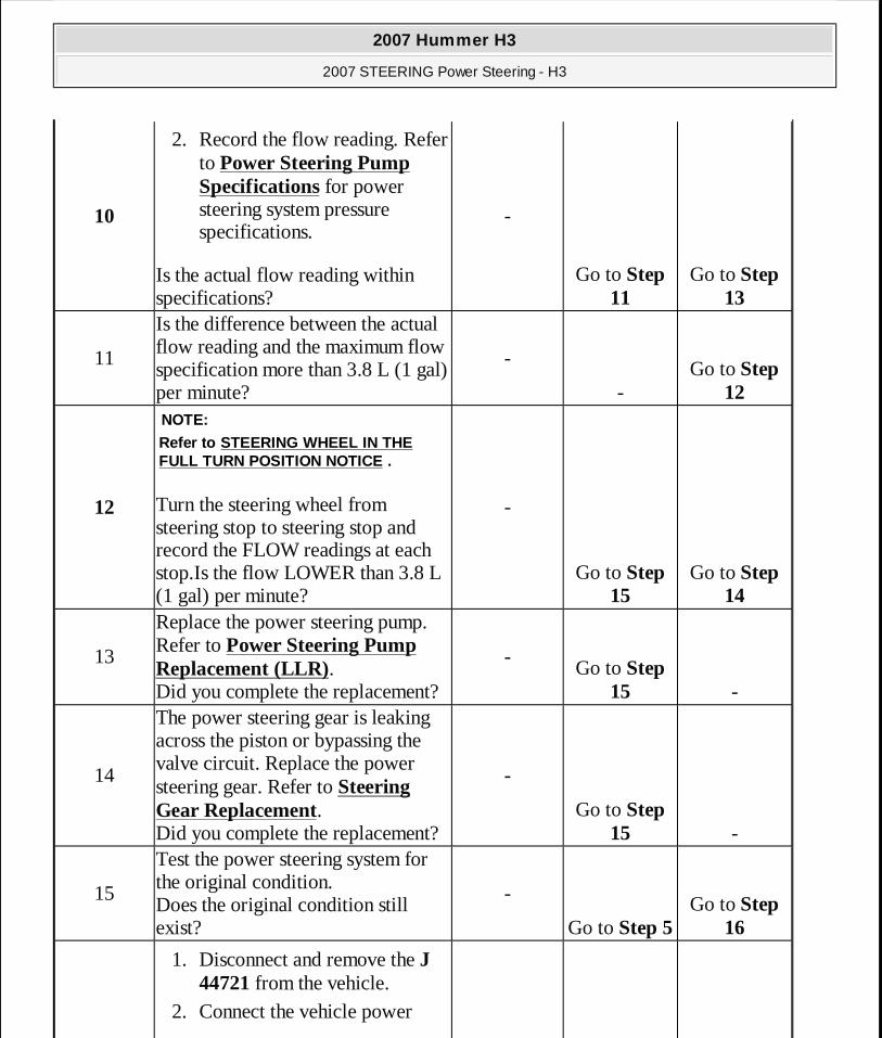
10
2. Record the flow reading. Refer to Power Steering Pump Specifications for power steering system pressure specifications.
Is the actual flow reading within specifications?
-
Go to Step 11
Go to Step 13
11
Is the difference between the actual flow reading and the maximum flow specification more than 3.8 L (1 gal) per minute?
-
-Go to Step
12
12 Turn the steering wheel from steering stop to steering stop and record the FLOW readings at each stop.Is the flow LOWER than 3.8 L (1 gal) per minute?
NOTE:
Refer to STEERING WHEEL IN THE FULL TURN POSITION NOTICE .
-
Go to Step 15
Go to Step 14
13
Replace the power steering pump. Refer to Power Steering Pump Replacement (LLR). Did you complete the replacement?
-Go to Step
15 -
14
The power steering gear is leaking across the piston or bypassing the valve circuit. Replace the power steering gear. Refer to Steering Gear Replacement. Did you complete the replacement?
-
Go to Step 15 -
15
Test the power steering system for the original condition. Does the original condition still exist?
-
Go to Step 5 Go to Step
16
1. Disconnect and remove the J 44721 from the vehicle.
2. Connect the vehicle power
2007 Hummer H3
2007 STEERING Power Steering - H3
MY
Sunday, March 29, 2009 9:33:34 PM Page 7 © 2005 Mitchell Repair Information Company, LLC.
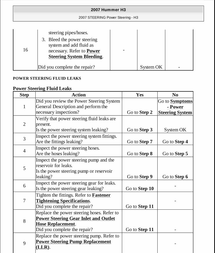
POWER STEERING FLUID LEAKS
Power Steering Fluid Leaks
16
steering pipes/hoses. 3. Bleed the power steering
system and add fluid as necessary. Refer to Power Steering System Bleeding.
Did you complete the repair?
-
System OK -
Step Action Yes No
1Did you review the Power Steering System General Description and perform the necessary inspections? Go to Step 2
Go to Symptoms - Power
Steering System
2Verify that power steering fluid leaks are present. Is the power steering system leaking? Go to Step 3 System OK
3 Inspect the power steering system fittings. Are the fittings leaking? Go to Step 7 Go to Step 4
4Inspect the power steering hoses. Are the hoses leaking? Go to Step 8 Go to Step 5
5
Inspect the power steering pump and the reservoir for leaks. Is the power steering pump or reservoir leaking? Go to Step 9 Go to Step 6
6Inspect the power steering gear for leaks. Is the power steering gear leaking? Go to Step 10
-
7Tighten the fittings. Refer to Fastener Tightening Specifications. Did you complete the repair? Go to Step 11
-
8
Replace the power steering hoses. Refer to Power Steering Gear Inlet and Outlet Hose Replacement. Did you complete the repair? Go to Step 11 -
9
Replace the power steering pump. Refer to Power Steering Pump Replacement (LLR).
-
2007 Hummer H3
2007 STEERING Power Steering - H3
MY
Sunday, March 29, 2009 9:33:34 PM Page 8 © 2005 Mitchell Repair Information Company, LLC.
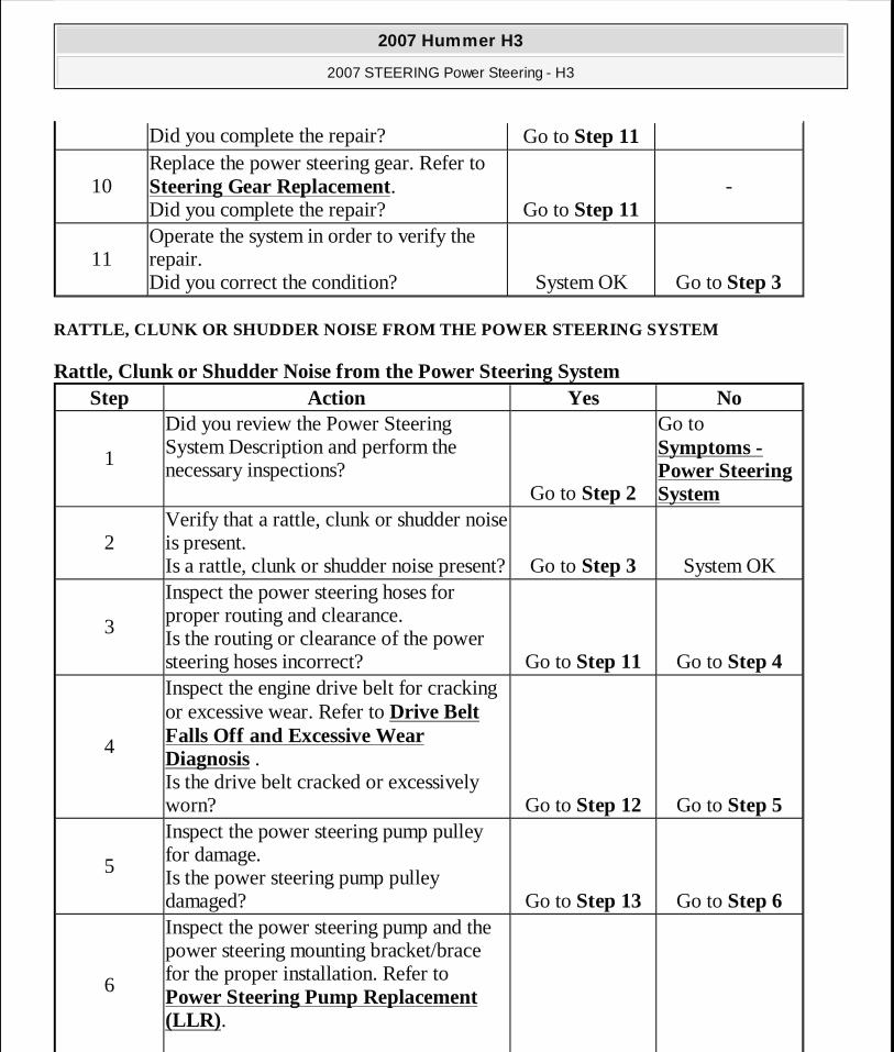
RATTLE, CLUNK OR SHUDDER NOISE FROM THE POWER STEERING SYSTEM
Rattle, Clunk or Shudder Noise from the Power Steering System
Did you complete the repair? Go to Step 11
10Replace the power steering gear. Refer to Steering Gear Replacement. Did you complete the repair? Go to Step 11
-
11Operate the system in order to verify the repair. Did you correct the condition? System OK Go to Step 3
Step Action Yes No
1
Did you review the Power Steering System Description and perform the necessary inspections?
Go to Step 2
Go to Symptoms - Power Steering System
2Verify that a rattle, clunk or shudder noise is present. Is a rattle, clunk or shudder noise present?Go to Step 3 System OK
3
Inspect the power steering hoses for proper routing and clearance. Is the routing or clearance of the power steering hoses incorrect? Go to Step 11 Go to Step 4
4
Inspect the engine drive belt for cracking or excessive wear. Refer to Drive Belt Falls Off and Excessive Wear Diagnosis . Is the drive belt cracked or excessively worn? Go to Step 12 Go to Step 5
5
Inspect the power steering pump pulley for damage. Is the power steering pump pulley damaged? Go to Step 13 Go to Step 6
6
Inspect the power steering pump and the power steering mounting bracket/brace for the proper installation. Refer to Power Steering Pump Replacement (LLR).
2007 Hummer H3
2007 STEERING Power Steering - H3
MY
Sunday, March 29, 2009 9:33:34 PM Page 9 © 2005 Mitchell Repair Information Company, LLC.
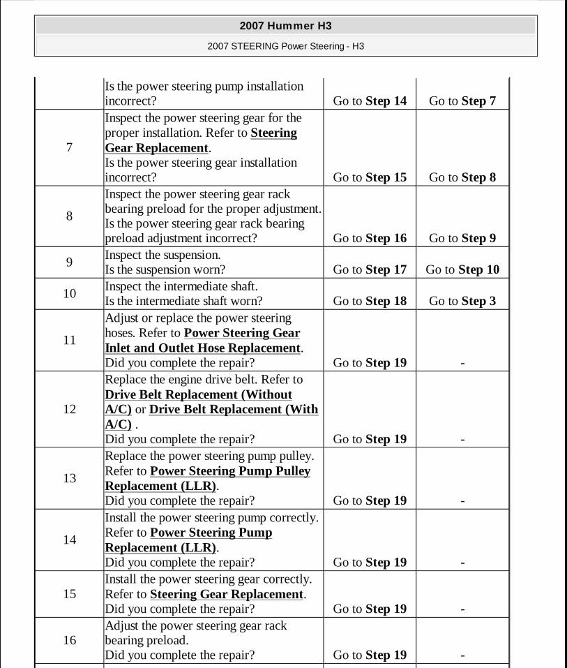
Is the power steering pump installation incorrect? Go to Step 14 Go to Step 7
7
Inspect the power steering gear for the proper installation. Refer to Steering Gear Replacement. Is the power steering gear installation incorrect? Go to Step 15 Go to Step 8
8
Inspect the power steering gear rack bearing preload for the proper adjustment. Is the power steering gear rack bearing preload adjustment incorrect? Go to Step 16 Go to Step 9
9Inspect the suspension. Is the suspension worn? Go to Step 17 Go to Step 10
10Inspect the intermediate shaft. Is the intermediate shaft worn? Go to Step 18 Go to Step 3
11
Adjust or replace the power steering hoses. Refer to Power Steering Gear Inlet and Outlet Hose Replacement. Did you complete the repair? Go to Step 19 -
12
Replace the engine drive belt. Refer to Drive Belt Replacement (Without A/C) or Drive Belt Replacement (With A/C) . Did you complete the repair? Go to Step 19 -
13
Replace the power steering pump pulley. Refer to Power Steering Pump Pulley Replacement (LLR). Did you complete the repair? Go to Step 19 -
14
Install the power steering pump correctly. Refer to Power Steering Pump Replacement (LLR). Did you complete the repair? Go to Step 19 -
15Install the power steering gear correctly. Refer to Steering Gear Replacement. Did you complete the repair? Go to Step 19 -
16Adjust the power steering gear rack bearing preload. Did you complete the repair? Go to Step 19 -
2007 Hummer H3
2007 STEERING Power Steering - H3
MY
Sunday, March 29, 2009 9:33:34 PM Page 10 © 2005 Mitchell Repair Information Company, LLC.
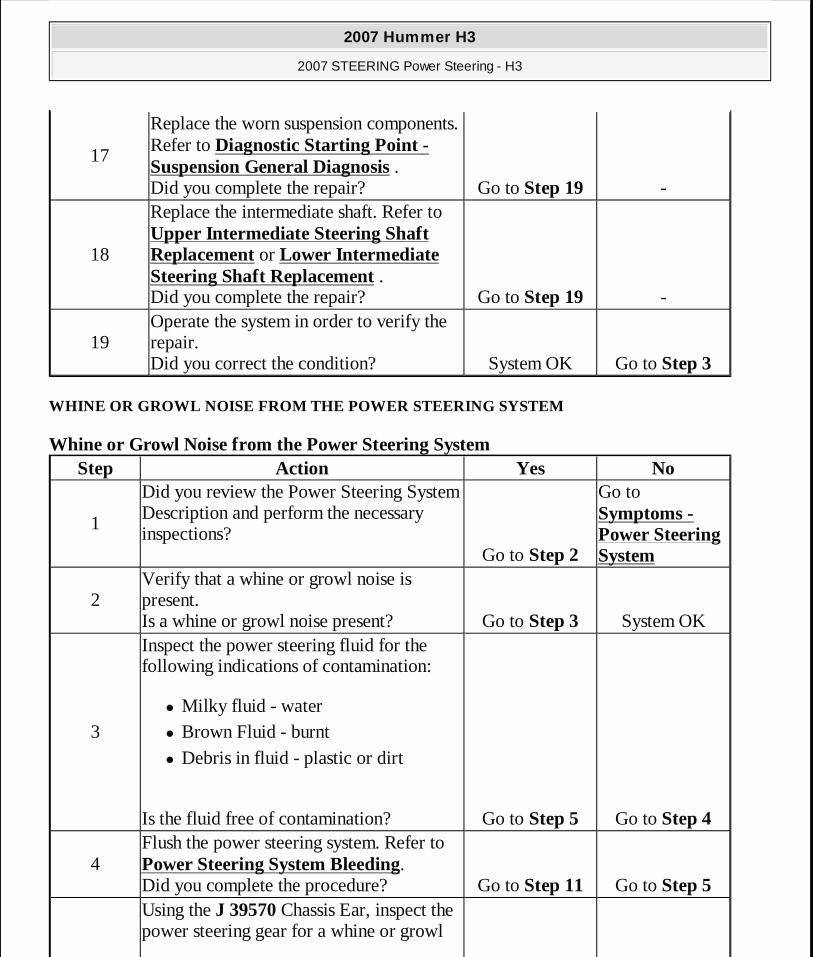
WHINE OR GROWL NOISE FROM THE POWER STEERING SYSTEM
Whine or Growl Noise from the Power Steering System
17
Replace the worn suspension components. Refer to Diagnostic Starting Point - Suspension General Diagnosis . Did you complete the repair? Go to Step 19 -
18
Replace the intermediate shaft. Refer to Upper Intermediate Steering Shaft Replacement or Lower Intermediate Steering Shaft Replacement . Did you complete the repair? Go to Step 19 -
19Operate the system in order to verify the repair. Did you correct the condition? System OK Go to Step 3
Step Action Yes No
1
Did you review the Power Steering System Description and perform the necessary inspections?
Go to Step 2
Go to Symptoms - Power Steering System
2Verify that a whine or growl noise is present. Is a whine or growl noise present? Go to Step 3 System OK
3
Inspect the power steering fluid for the following indications of contamination:
� Milky fluid - water � Brown Fluid - burnt � Debris in fluid - plastic or dirt
Is the fluid free of contamination? Go to Step 5 Go to Step 4
4Flush the power steering system. Refer to Power Steering System Bleeding. Did you complete the procedure? Go to Step 11 Go to Step 5 Using the J 39570 Chassis Ear, inspect the power steering gear for a whine or growl
2007 Hummer H3
2007 STEERING Power Steering - H3
MY
Sunday, March 29, 2009 9:33:34 PM Page 11 © 2005 Mitchell Repair Information Company, LLC.
POOR RETURN OF STEERING WHEEL
Poor Return of Steering Wheel
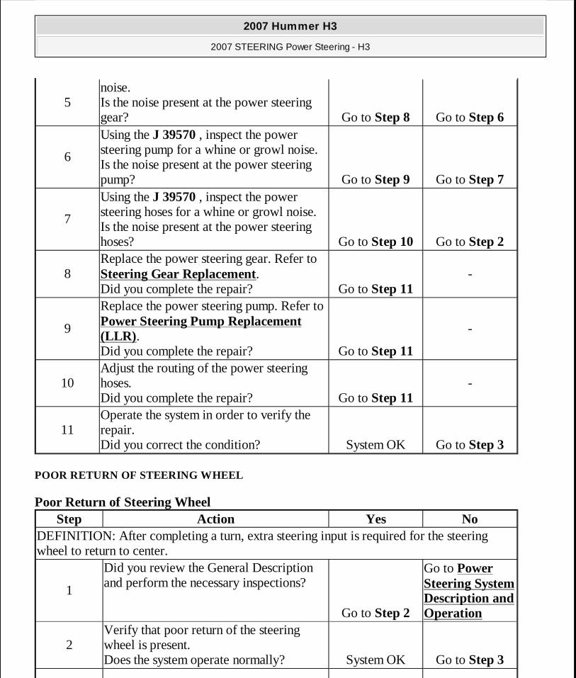
5noise. Is the noise present at the power steering gear? Go to Step 8 Go to Step 6
6
Using the J 39570 , inspect the power steering pump for a whine or growl noise. Is the noise present at the power steering pump? Go to Step 9 Go to Step 7
7
Using the J 39570 , inspect the power steering hoses for a whine or growl noise. Is the noise present at the power steering hoses? Go to Step 10 Go to Step 2
8Replace the power steering gear. Refer to Steering Gear Replacement. Did you complete the repair? Go to Step 11
-
9
Replace the power steering pump. Refer to Power Steering Pump Replacement (LLR). Did you complete the repair? Go to Step 11
-
10Adjust the routing of the power steering hoses. Did you complete the repair? Go to Step 11
-
11Operate the system in order to verify the repair. Did you correct the condition? System OK Go to Step 3
Step Action Yes NoDEFINITION: After completing a turn, extra steering input is required for the steering wheel to return to center.
1
Did you review the General Description and perform the necessary inspections?
Go to Step 2
Go to Power Steering System Description and Operation
2Verify that poor return of the steering wheel is present. Does the system operate normally? System OK Go to Step 3
2007 Hummer H3
2007 STEERING Power Steering - H3
MY
Sunday, March 29, 2009 9:33:34 PM Page 12 © 2005 Mitchell Repair Information Company, LLC.
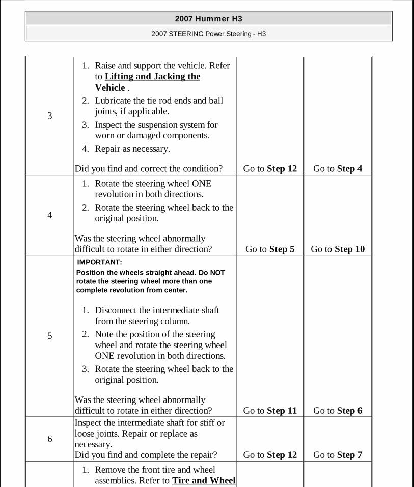
3
1. Raise and support the vehicle. Refer to Lifting and Jacking the Vehicle .
2. Lubricate the tie rod ends and ball joints, if applicable.
3. Inspect the suspension system for worn or damaged components.
4. Repair as necessary.
Did you find and correct the condition? Go to Step 12 Go to Step 4
4
1. Rotate the steering wheel ONE revolution in both directions.
2. Rotate the steering wheel back to the original position.
Was the steering wheel abnormally difficult to rotate in either direction? Go to Step 5 Go to Step 10
5
1. Disconnect the intermediate shaft from the steering column.
2. Note the position of the steering wheel and rotate the steering wheel ONE revolution in both directions.
3. Rotate the steering wheel back to the original position.
Was the steering wheel abnormally difficult to rotate in either direction?
IMPORTANT:
Position the wheels straight ahead. Do NOT rotate the steering wheel more than one complete revolution from center.
Go to Step 11 Go to Step 6
6
Inspect the intermediate shaft for stiff or loose joints. Repair or replace as necessary. Did you find and complete the repair? Go to Step 12 Go to Step 7
1. Remove the front tire and wheel assemblies. Refer to Tire and Wheel
2007 Hummer H3
2007 STEERING Power Steering - H3
MY
Sunday, March 29, 2009 9:33:34 PM Page 13 © 2005 Mitchell Repair Information Company, LLC.
STEERING EFFORT TOO EASY IN ONE OR BOTH DIRECTIONS
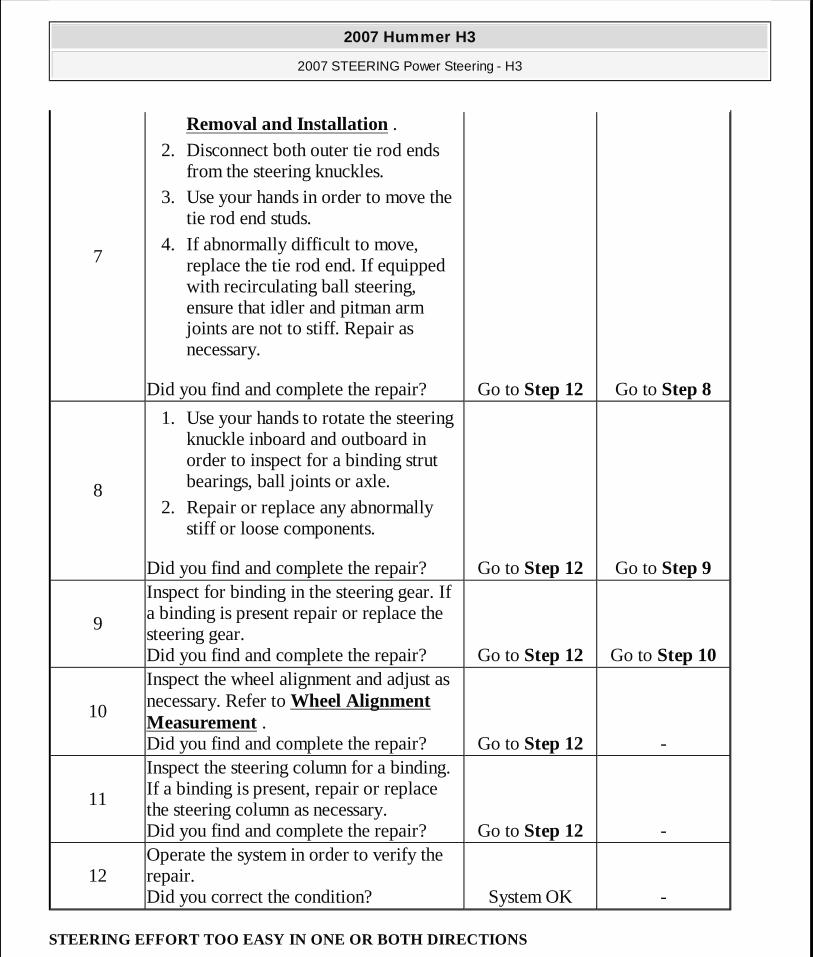
7
Removal and Installation . 2. Disconnect both outer tie rod ends
from the steering knuckles. 3. Use your hands in order to move the
tie rod end studs. 4. If abnormally difficult to move,
replace the tie rod end. If equipped with recirculating ball steering, ensure that idler and pitman arm joints are not to stiff. Repair as necessary.
Did you find and complete the repair? Go to Step 12 Go to Step 8
8
1. Use your hands to rotate the steering knuckle inboard and outboard in order to inspect for a binding strut bearings, ball joints or axle.
2. Repair or replace any abnormally stiff or loose components.
Did you find and complete the repair? Go to Step 12 Go to Step 9
9
Inspect for binding in the steering gear. If a binding is present repair or replace the steering gear. Did you find and complete the repair? Go to Step 12 Go to Step 10
10
Inspect the wheel alignment and adjust as necessary. Refer to Wheel Alignment Measurement . Did you find and complete the repair? Go to Step 12 -
11
Inspect the steering column for a binding. If a binding is present, repair or replace the steering column as necessary. Did you find and complete the repair? Go to Step 12 -
12Operate the system in order to verify the repair. Did you correct the condition? System OK -
2007 Hummer H3
2007 STEERING Power Steering - H3
MY
Sunday, March 29, 2009 9:33:34 PM Page 14 © 2005 Mitchell Repair Information Company, LLC.
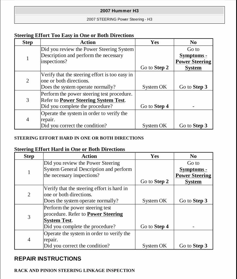
Steering Effort Too Easy in One or Both Directions
STEERING EFFORT HARD IN ONE OR BOTH DIRECTIONS
Steering Effort Hard in One or Both Directions
REPAIR INSTRUCTIONS
RACK AND PINION STEERING LINKAGE INSPECTION
Step Action Yes No
1
Did you review the Power Steering System Description and perform the necessary inspections?
Go to Step 2
Go to Symptoms -
Power Steering System
2Verify that the steering effort is too easy in one or both directions. Does the system operate normally? System OK Go to Step 3
3Perform the power steering test procedure. Refer to Power Steering System Test. Did you complete the procedure? Go to Step 4 -
4Operate the system in order to verify the repair. Did you correct the condition? System OK Go to Step 3
Step Action Yes No
1
Did you review the Power Steering System General Description and perform the necessary inspections?
Go to Step 2
Go to Symptoms -
Power Steering System
2Verify that the steering effort is hard in one or both directions. Does the system operate normally? System OK Go to Step 3
3
Perform the power steering test procedure. Refer to Power Steering System Test. Did you complete the procedure? Go to Step 4 -
4Operate the system in order to verify the repair. Did you correct the condition? System OK Go to Step 3
2007 Hummer H3
2007 STEERING Power Steering - H3
MY
Sunday, March 29, 2009 9:33:34 PM Page 15 © 2005 Mitchell Repair Information Company, LLC.
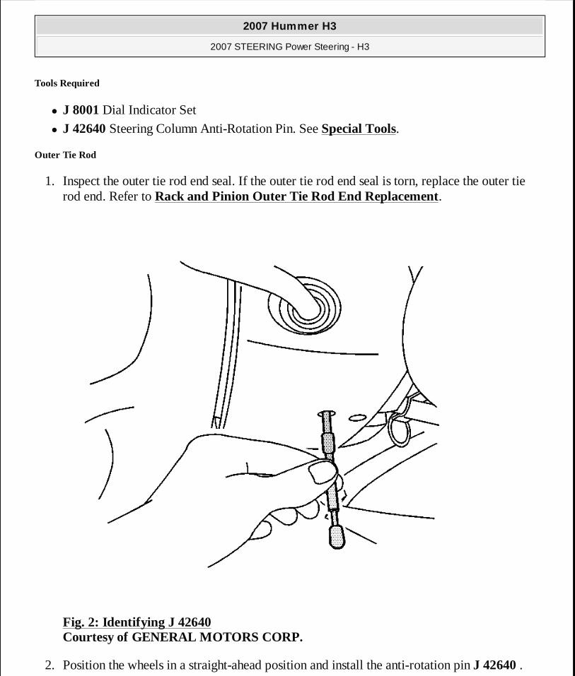
Tools Required
� J 8001 Dial Indicator Set
� J 42640 Steering Column Anti-Rotation Pin. See Special Tools.
Outer Tie Rod
1. Inspect the outer tie rod end seal. If the outer tie rod end seal is torn, replace the outer tie rod end. Refer to Rack and Pinion Outer Tie Rod End Replacement.
Fig. 2: Identifying J 42640 Courtesy of GENERAL MOTORS CORP.
2. Position the wheels in a straight-ahead position and install the anti-rotation pin J 42640 .
2007 Hummer H3
2007 STEERING Power Steering - H3
MY
Sunday, March 29, 2009 9:33:34 PM Page 16 © 2005 Mitchell Repair Information Company, LLC.
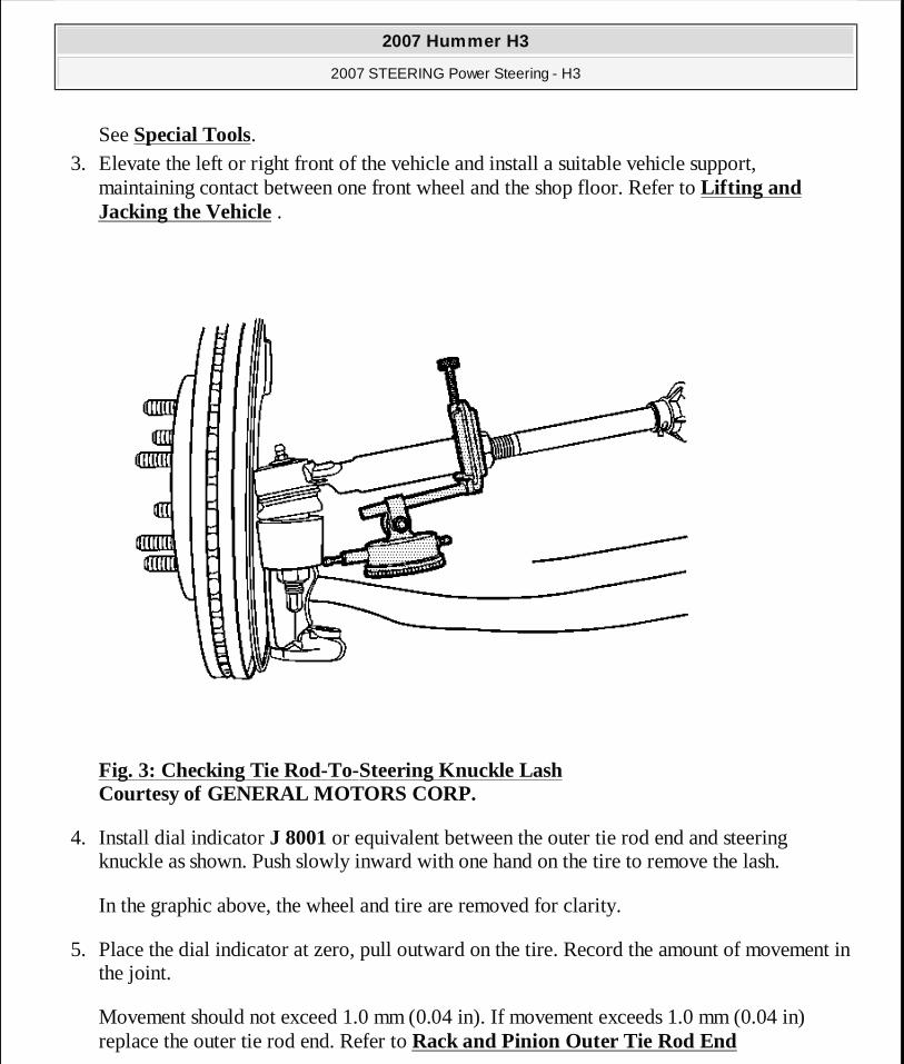
See Special Tools. 3. Elevate the left or right front of the vehicle and install a suitable vehicle support,
maintaining contact between one front wheel and the shop floor. Refer to Lifting and Jacking the Vehicle .
Fig. 3: Checking Tie Rod-To-Steering Knuckle Lash Courtesy of GENERAL MOTORS CORP.
4. Install dial indicator J 8001 or equivalent between the outer tie rod end and steering knuckle as shown. Push slowly inward with one hand on the tire to remove the lash.
In the graphic above, the wheel and tire are removed for clarity.
5. Place the dial indicator at zero, pull outward on the tire. Record the amount of movement in the joint.
Movement should not exceed 1.0 mm (0.04 in). If movement exceeds 1.0 mm (0.04 in) replace the outer tie rod end. Refer to Rack and Pinion Outer Tie Rod End
2007 Hummer H3
2007 STEERING Power Steering - H3
MY
Sunday, March 29, 2009 9:33:34 PM Page 17 © 2005 Mitchell Repair Information Company, LLC.
Replacement.
6. Repeat this procedure for the other side of the vehicle.
POWER STEERING SYSTEM BLEEDING
1. Fill pump reservoir with fluid to minimum system level, FULL COLD level or middle of hash mark on cap stick fluid level indicator.
2. If equipped with hydro-boost, fully charge the hydro-boost accumulator using the following procedure:
1. Start the engine. 2. Firmly apply the brake pedal 10-15 times. 3. Turn the engine OFF.
3. Raise the vehicle until the front wheels are off the ground. Refer to Lifting and Jacking the Vehicle .
4. Key on engine OFF, turn the steering wheel from stop to stop 12 times.
Vehicles equipped with hydro-boost systems or longer length power steering hoses may
IMPORTANT:� Use clean, new power steering fluid type only. See the
Maintenance and Lubrication subsection for fluid specifications. Refer to Fluid and Lubricant Recommendations .
� Hoses touching the frame, body or engine may cause system noise. Verify that the hoses do not touch any other part of the vehicle.
� Loose connections may not leak, but could allow air into the steering system. Verify that all hose connections are tight.
IMPORTANT: Power steering fluid level must be maintained throughout bleed procedure.
IMPORTANT: With hydro-boost only, the oil level will appear falsely high if the hydro-boost accumulator is not fully charged. Do not apply the brake pedal with the engine OFF. This will discharge the hydro-boost accumulator.
2007 Hummer H3
2007 STEERING Power Steering - H3
MY
Sunday, March 29, 2009 9:33:34 PM Page 18 © 2005 Mitchell Repair Information Company, LLC.
require turns up to 15 to 20 stop to stops.
5. Verify power steering fluid level per operating specification. Refer to Checking and Adding Power Steering Fluid.
6. Start the engine. Rotate steering wheel from left to right. Check for sign of cavitation or fluid aeration (pump noise/whining).
7. Verify the fluid level. Repeat the bleed procedure, if necessary.
CHECKING AND ADDING POWER STEERING FLUID
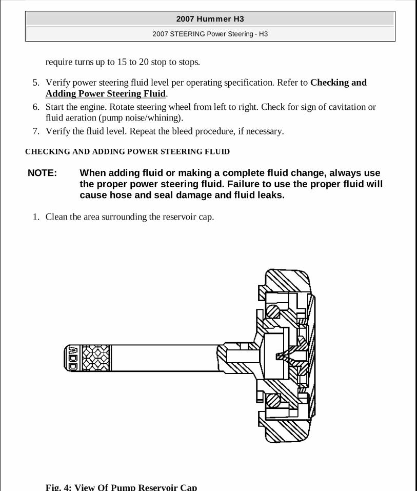
1. Clean the area surrounding the reservoir cap.
Fig. 4: View Of Pump Reservoir Cap
NOTE: When adding fluid or making a complete fluid change, always use the proper power steering fluid. Failure to use the proper fluid will cause hose and seal damage and fluid leaks.
2007 Hummer H3
2007 STEERING Power Steering - H3
MY
Sunday, March 29, 2009 9:33:34 PM Page 19 © 2005 Mitchell Repair Information Company, LLC.
Courtesy of GENERAL MOTORS CORP.
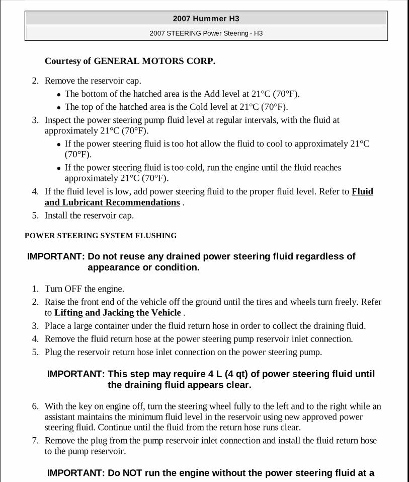
2. Remove the reservoir cap. � The bottom of the hatched area is the Add level at 21°C (70°F). � The top of the hatched area is the Cold level at 21°C (70°F).
3. Inspect the power steering pump fluid level at regular intervals, with the fluid at approximately 21°C (70°F).
� If the power steering fluid is too hot allow the fluid to cool to approximately 21°C (70°F).
� If the power steering fluid is too cold, run the engine until the fluid reaches approximately 21°C (70°F).
4. If the fluid level is low, add power steering fluid to the proper fluid level. Refer to Fluid and Lubricant Recommendations .
5. Install the reservoir cap.
POWER STEERING SYSTEM FLUSHING
1. Turn OFF the engine. 2. Raise the front end of the vehicle off the ground until the tires and wheels turn freely. Refer
to Lifting and Jacking the Vehicle . 3. Place a large container under the fluid return hose in order to collect the draining fluid. 4. Remove the fluid return hose at the power steering pump reservoir inlet connection. 5. Plug the reservoir return hose inlet connection on the power steering pump.
6. With the key on engine off, turn the steering wheel fully to the left and to the right while an assistant maintains the minimum fluid level in the reservoir using new approved power steering fluid. Continue until the fluid from the return hose runs clear.
7. Remove the plug from the pump reservoir inlet connection and install the fluid return hose to the pump reservoir.
IMPORTANT: Do not reuse any drained power steering fluid regardless of appearance or condition.
IMPORTANT: This step may require 4 L (4 qt) of power steering fluid until the draining fluid appears clear.
IMPORTANT: Do NOT run the engine without the power steering fluid at a
2007 Hummer H3
2007 STEERING Power Steering - H3
MY
Sunday, March 29, 2009 9:33:34 PM Page 20 © 2005 Mitchell Repair Information Company, LLC.
8. Bleed the power steering system. Refer to Power Steering System Bleeding. 9. Inspect the power steering fluid for the following indications of contamination:
� Milky fluid - water � Brown fluid - burnt � Plastic debris or dirt chunks
10. If the fluid is contaminated, repeat steps 2-9. 11. Lower the vehicle and check the Power Steering system for leaks.
POWER STEERING PUMP PULLEY REPLACEMENT (LLR)
Tools Required
� J 25033-C Pulley Installer. See Special Tools. � J 25034-C Pulley Remover.
Removal Procedure
1. Remove the drive belt. Refer to Drive Belt Replacement (Without A/C) or Drive Belt Replacement (With A/C) .
minimum system level.
2007 Hummer H3
2007 STEERING Power Steering - H3
MY
Sunday, March 29, 2009 9:33:34 PM Page 21 © 2005 Mitchell Repair Information Company, LLC.
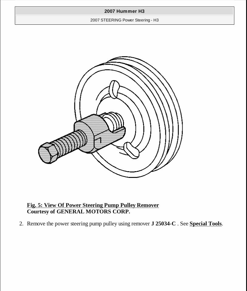
Fig. 5: View Of Power Steering Pump Pulley Remover Courtesy of GENERAL MOTORS CORP.
2. Remove the power steering pump pulley using remover J 25034-C . See Special Tools.
2007 Hummer H3
2007 STEERING Power Steering - H3
MY
Sunday, March 29, 2009 9:33:34 PM Page 22 © 2005 Mitchell Repair Information Company, LLC.
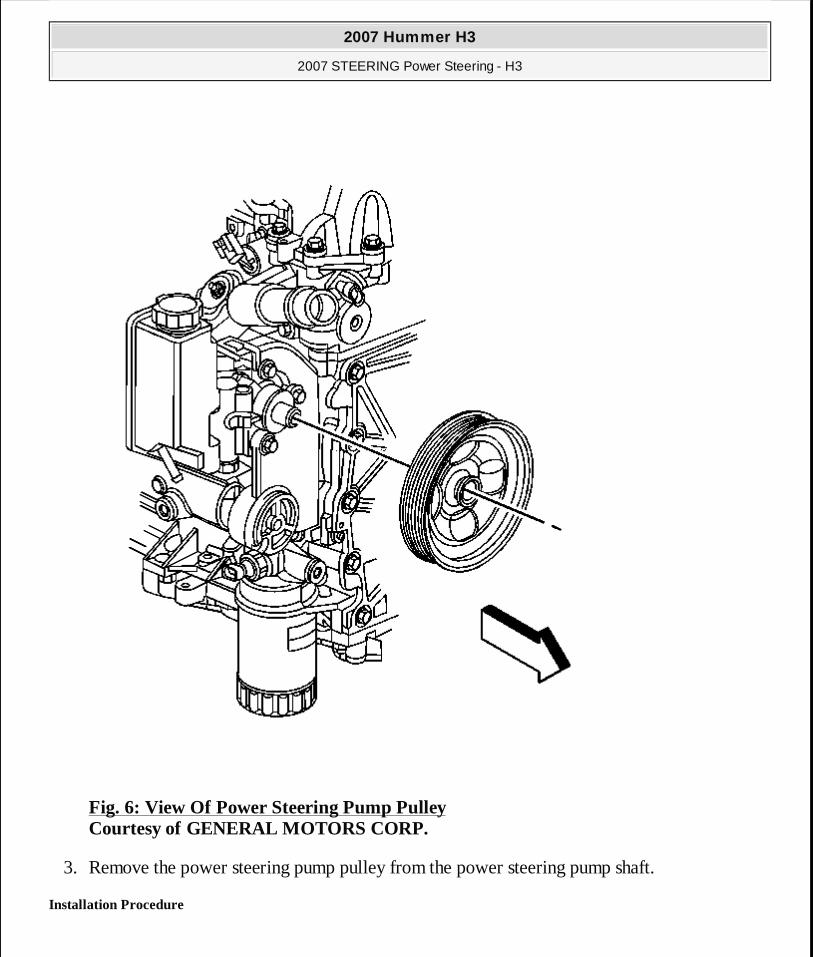
Fig. 6: View Of Power Steering Pump Pulley Courtesy of GENERAL MOTORS CORP.
3. Remove the power steering pump pulley from the power steering pump shaft.
Installation Procedure
2007 Hummer H3
2007 STEERING Power Steering - H3
MY
Sunday, March 29, 2009 9:33:34 PM Page 23 © 2005 Mitchell Repair Information Company, LLC.
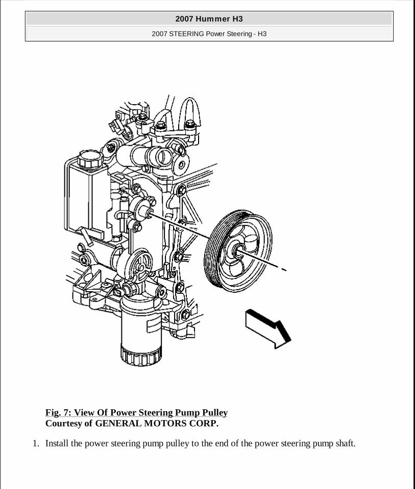
Fig. 7: View Of Power Steering Pump Pulley Courtesy of GENERAL MOTORS CORP.
1. Install the power steering pump pulley to the end of the power steering pump shaft.
2007 Hummer H3
2007 STEERING Power Steering - H3
MY
Sunday, March 29, 2009 9:33:34 PM Page 24 © 2005 Mitchell Repair Information Company, LLC.
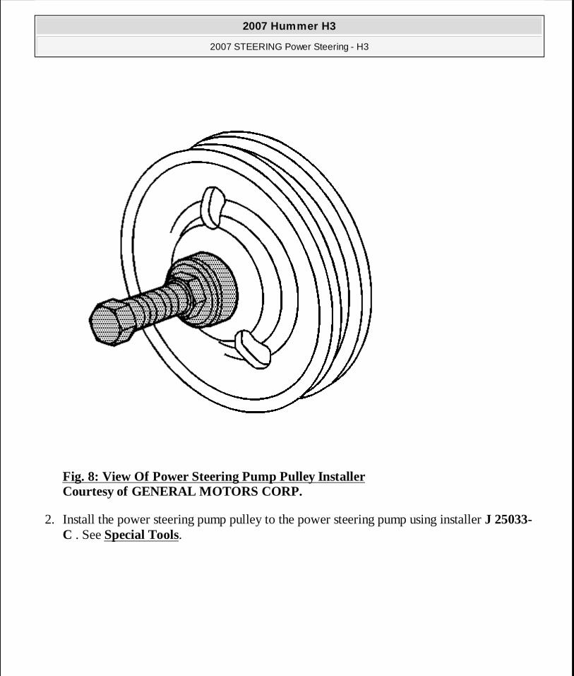
Fig. 8: View Of Power Steering Pump Pulley Installer Courtesy of GENERAL MOTORS CORP.
2. Install the power steering pump pulley to the power steering pump using installer J 25033-C . See Special Tools.
2007 Hummer H3
2007 STEERING Power Steering - H3
MY
Sunday, March 29, 2009 9:33:34 PM Page 25 © 2005 Mitchell Repair Information Company, LLC.
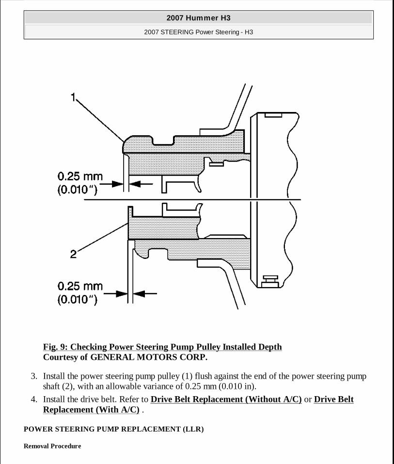
Fig. 9: Checking Power Steering Pump Pulley Installed Depth Courtesy of GENERAL MOTORS CORP.
3. Install the power steering pump pulley (1) flush against the end of the power steering pump shaft (2), with an allowable variance of 0.25 mm (0.010 in).
4. Install the drive belt. Refer to Drive Belt Replacement (Without A/C) or Drive Belt Replacement (With A/C) .
POWER STEERING PUMP REPLACEMENT (LLR)
Removal Procedure
2007 Hummer H3
2007 STEERING Power Steering - H3
MY
Sunday, March 29, 2009 9:33:34 PM Page 26 © 2005 Mitchell Repair Information Company, LLC.
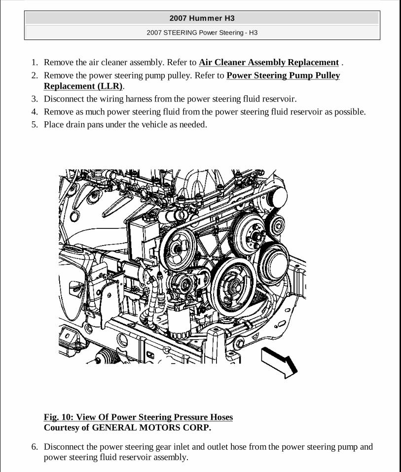
1. Remove the air cleaner assembly. Refer to Air Cleaner Assembly Replacement . 2. Remove the power steering pump pulley. Refer to Power Steering Pump Pulley
Replacement (LLR). 3. Disconnect the wiring harness from the power steering fluid reservoir. 4. Remove as much power steering fluid from the power steering fluid reservoir as possible. 5. Place drain pans under the vehicle as needed.
Fig. 10: View Of Power Steering Pressure Hoses Courtesy of GENERAL MOTORS CORP.
6. Disconnect the power steering gear inlet and outlet hose from the power steering pump and power steering fluid reservoir assembly.
2007 Hummer H3
2007 STEERING Power Steering - H3
MY
Sunday, March 29, 2009 9:33:34 PM Page 27 © 2005 Mitchell Repair Information Company, LLC.
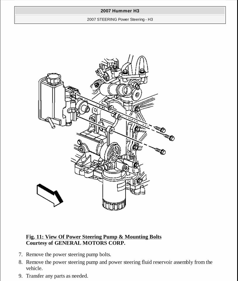
Fig. 11: View Of Power Steering Pump & Mounting Bolts Courtesy of GENERAL MOTORS CORP.
7. Remove the power steering pump bolts. 8. Remove the power steering pump and power steering fluid reservoir assembly from the
vehicle. 9. Transfer any parts as needed.
2007 Hummer H3
2007 STEERING Power Steering - H3
MY
Sunday, March 29, 2009 9:33:34 PM Page 28 © 2005 Mitchell Repair Information Company, LLC.
Installation Procedure
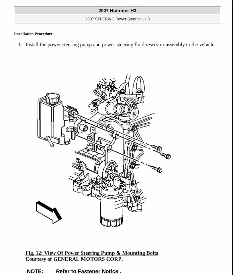
1. Install the power steering pump and power steering fluid reservoir assembly to the vehicle.
Fig. 12: View Of Power Steering Pump & Mounting Bolts Courtesy of GENERAL MOTORS CORP.
NOTE: Refer to Fastener Notice .
2007 Hummer H3
2007 STEERING Power Steering - H3
MY
Sunday, March 29, 2009 9:33:34 PM Page 29 © 2005 Mitchell Repair Information Company, LLC.
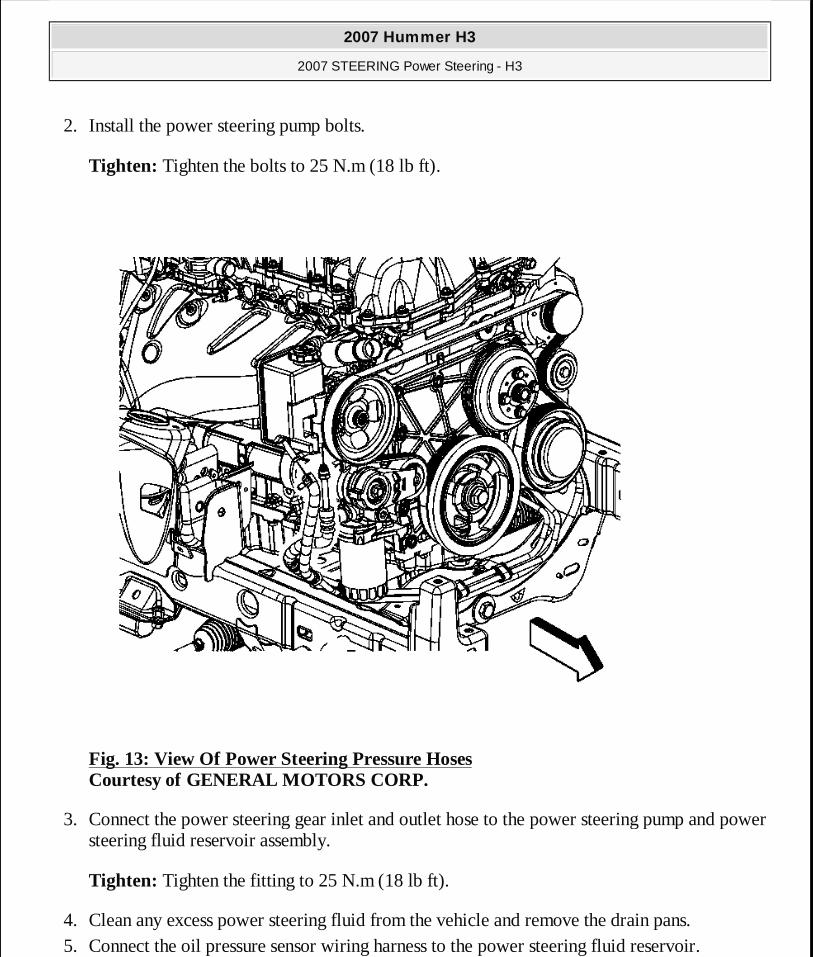
2. Install the power steering pump bolts.
Tighten: Tighten the bolts to 25 N.m (18 lb ft).
Fig. 13: View Of Power Steering Pressure Hoses Courtesy of GENERAL MOTORS CORP.
3. Connect the power steering gear inlet and outlet hose to the power steering pump and power steering fluid reservoir assembly.
Tighten: Tighten the fitting to 25 N.m (18 lb ft).
4. Clean any excess power steering fluid from the vehicle and remove the drain pans. 5. Connect the oil pressure sensor wiring harness to the power steering fluid reservoir.
2007 Hummer H3
2007 STEERING Power Steering - H3
MY
Sunday, March 29, 2009 9:33:34 PM Page 30 © 2005 Mitchell Repair Information Company, LLC.
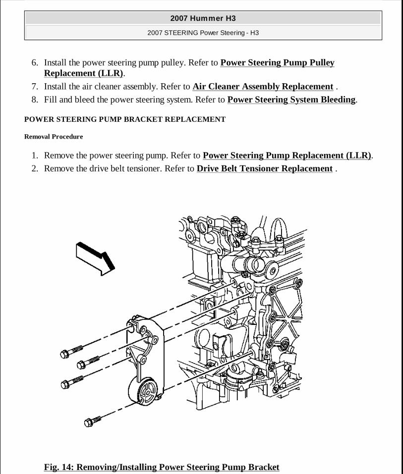
6. Install the power steering pump pulley. Refer to Power Steering Pump Pulley Replacement (LLR).
7. Install the air cleaner assembly. Refer to Air Cleaner Assembly Replacement . 8. Fill and bleed the power steering system. Refer to Power Steering System Bleeding.
POWER STEERING PUMP BRACKET REPLACEMENT
Removal Procedure
1. Remove the power steering pump. Refer to Power Steering Pump Replacement (LLR). 2. Remove the drive belt tensioner. Refer to Drive Belt Tensioner Replacement .
Fig. 14: Removing/Installing Power Steering Pump Bracket
2007 Hummer H3
2007 STEERING Power Steering - H3
MY
Sunday, March 29, 2009 9:33:34 PM Page 31 © 2005 Mitchell Repair Information Company, LLC.
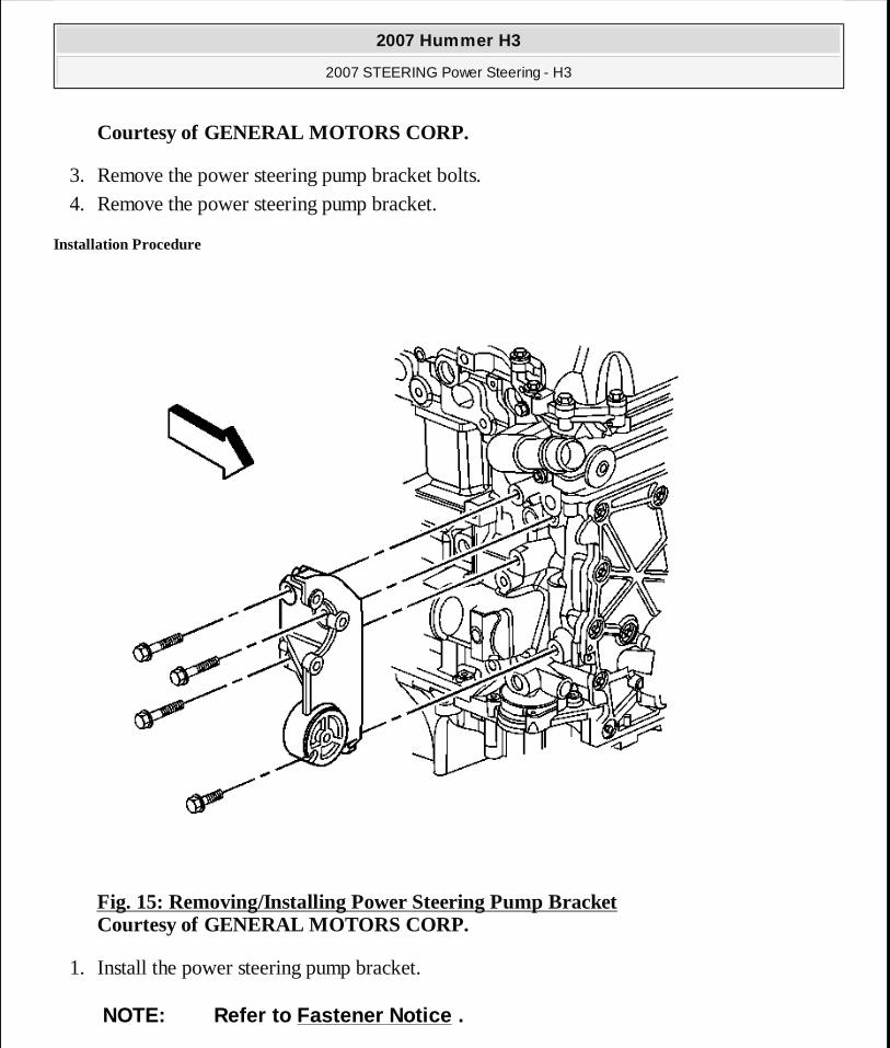
Courtesy of GENERAL MOTORS CORP.
3. Remove the power steering pump bracket bolts. 4. Remove the power steering pump bracket.
Installation Procedure
Fig. 15: Removing/Installing Power Steering Pump Bracket Courtesy of GENERAL MOTORS CORP.
1. Install the power steering pump bracket.
NOTE: Refer to Fastener Notice .
2007 Hummer H3
2007 STEERING Power Steering - H3
MY
Sunday, March 29, 2009 9:33:34 PM Page 32 © 2005 Mitchell Repair Information Company, LLC.
2. Install the power steering pump bracket bolts.
Tighten: Tighten the bolts to 50 N.m (37 lb ft).
3. Install the drive belt tensioner. Refer to Drive Belt Tensioner Replacement . 4. Install the power steering pump. Refer to Power Steering Pump Replacement (LLR).
RACK AND PINION OUTER TIE ROD END REPLACEMENT
Tools Required
J 24319-B Steering Linkage and Tie Rod Puller. See Special Tools.
Removal Procedure
1. Remove the front tire and wheel assembly. Refer to Tire and Wheel Removal and Installation .
2007 Hummer H3
2007 STEERING Power Steering - H3
MY
Sunday, March 29, 2009 9:33:35 PM Page 33 © 2005 Mitchell Repair Information Company, LLC.
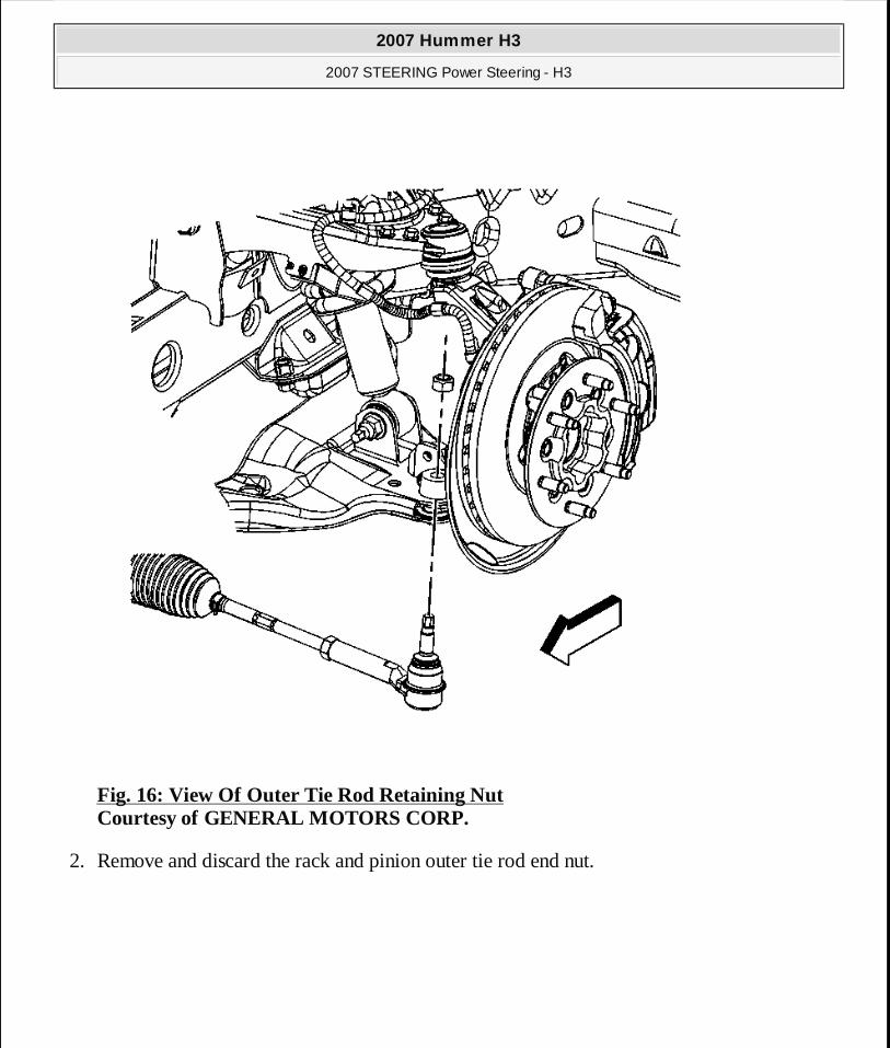
Fig. 16: View Of Outer Tie Rod Retaining Nut Courtesy of GENERAL MOTORS CORP.
2. Remove and discard the rack and pinion outer tie rod end nut.
2007 Hummer H3
2007 STEERING Power Steering - H3
MY
Sunday, March 29, 2009 9:33:35 PM Page 34 © 2005 Mitchell Repair Information Company, LLC.
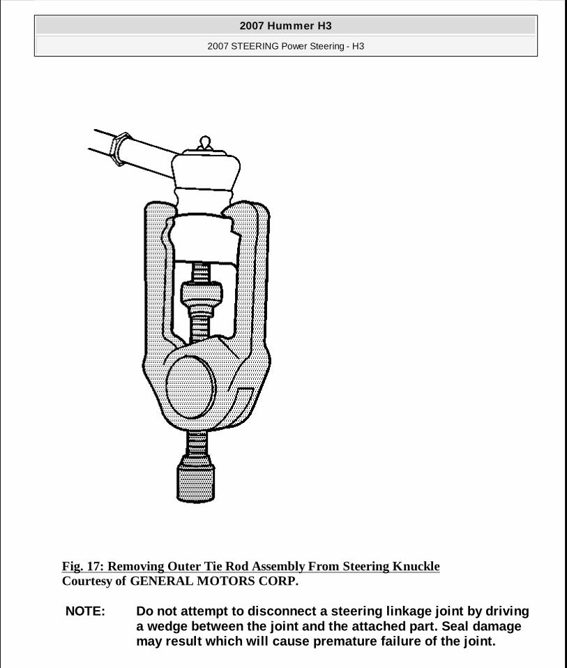
Fig. 17: Removing Outer Tie Rod Assembly From Steering Knuckle Courtesy of GENERAL MOTORS CORP.
NOTE: Do not attempt to disconnect a steering linkage joint by driving a wedge between the joint and the attached part. Seal damage may result which will cause premature failure of the joint.
2007 Hummer H3
2007 STEERING Power Steering - H3
MY
Sunday, March 29, 2009 9:33:35 PM Page 35 © 2005 Mitchell Repair Information Company, LLC.
3. Disconnect the rack and pinion outer tie rod end from the steering knuckle using puller J 24319-B . See Special Tools.
4. Loosen the rack and pinion inner tie rod nut and remove the rack and pinion outer tie rod end.
5. Discard the rack and pinion inner tie rod nut. 6. Clean the tapered surface of the steering knuckle.
Installation Procedure
1. Lubricate the rack and pinion inner tie rod threads with a suitable chassis lubricant. 2. Install a new rack and pinion inner tie rod nut in the same position as the old one. 3. Install the rack and pinion outer tie rod end to the rack and pinion inner tie rod.
IMPORTANT: Mark the location of the rack and pinion inner tie rod nut.
2007 Hummer H3
2007 STEERING Power Steering - H3
MY
Sunday, March 29, 2009 9:33:35 PM Page 36 © 2005 Mitchell Repair Information Company, LLC.
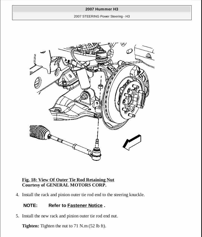
Fig. 18: View Of Outer Tie Rod Retaining Nut Courtesy of GENERAL MOTORS CORP.
4. Install the rack and pinion outer tie rod end to the steering knuckle.
5. Install the new rack and pinion outer tie rod end nut.
Tighten: Tighten the nut to 71 N.m (52 lb ft).
NOTE: Refer to Fastener Notice .
2007 Hummer H3
2007 STEERING Power Steering - H3
MY
Sunday, March 29, 2009 9:33:35 PM Page 37 © 2005 Mitchell Repair Information Company, LLC.
6. Tighten the rack and pinion inner tie rod nut against the rack and pinion outer tie rod end.
7. Install the front tire and wheel assembly. Refer to Tire and Wheel Removal and Installation .
8. Adjust the front toe. Refer to Front Toe Adjustment .
RACK AND PINION INNER TIE ROD REPLACEMENT
Tools Required
J 34028 Inner Tie Rod Wrench. See Special Tools.
Removal Procedure
1. Remove the steering gear boot. Refer to Steering Gear Boot Replacement - On Vehicle.
IMPORTANT: After removing the boot, inspect the inner tie rod for evidence of corrosion or contamination. If none is evident, continue with the repair. If corrosion or contamination is evident, replace the steering gear.
2007 Hummer H3
2007 STEERING Power Steering - H3
MY
Sunday, March 29, 2009 9:33:35 PM Page 38 © 2005 Mitchell Repair Information Company, LLC.
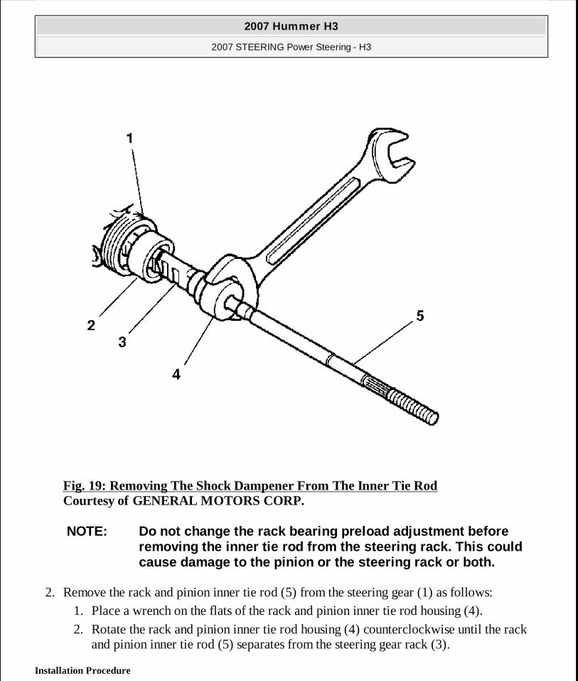
Fig. 19: Removing The Shock Dampener From The Inner Tie Rod Courtesy of GENERAL MOTORS CORP.
2. Remove the rack and pinion inner tie rod (5) from the steering gear (1) as follows: 1. Place a wrench on the flats of the rack and pinion inner tie rod housing (4). 2. Rotate the rack and pinion inner tie rod housing (4) counterclockwise until the rack
and pinion inner tie rod (5) separates from the steering gear rack (3).
Installation Procedure
NOTE: Do not change the rack bearing preload adjustment before removing the inner tie rod from the steering rack. This could cause damage to the pinion or the steering rack or both.
2007 Hummer H3
2007 STEERING Power Steering - H3
MY
Sunday, March 29, 2009 9:33:35 PM Page 39 © 2005 Mitchell Repair Information Company, LLC.
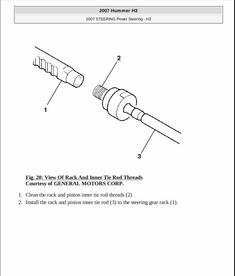
Fig. 20: View Of Rack And Inner Tie Rod Threads Courtesy of GENERAL MOTORS CORP.
1. Clean the rack and pinion inner tie rod threads (2) 2. Install the rack and pinion inner tie rod (3) to the steering gear rack (1).
2007 Hummer H3
2007 STEERING Power Steering - H3
MY
Sunday, March 29, 2009 9:33:35 PM Page 40 © 2005 Mitchell Repair Information Company, LLC.
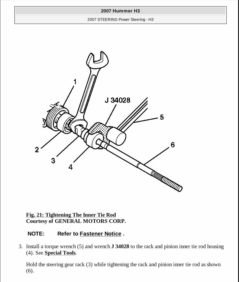
Fig. 21: Tightening The Inner Tie Rod Courtesy of GENERAL MOTORS CORP.
3. Install a torque wrench (5) and wrench J 34028 to the rack and pinion inner tie rod housing (4). See Special Tools.
Hold the steering gear rack (3) while tightening the rack and pinion inner tie rod as shown (6).
NOTE: Refer to Fastener Notice .
2007 Hummer H3
2007 STEERING Power Steering - H3
MY
Sunday, March 29, 2009 9:33:35 PM Page 41 © 2005 Mitchell Repair Information Company, LLC.
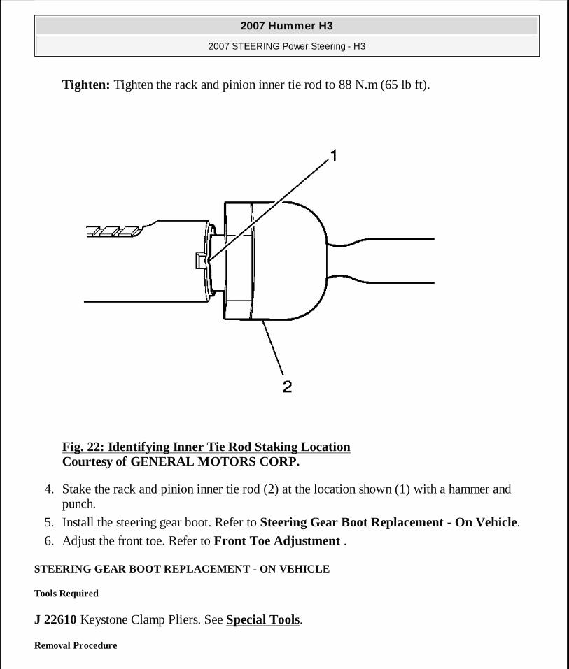
Tighten: Tighten the rack and pinion inner tie rod to 88 N.m (65 lb ft).
Fig. 22: Identifying Inner Tie Rod Staking Location Courtesy of GENERAL MOTORS CORP.
4. Stake the rack and pinion inner tie rod (2) at the location shown (1) with a hammer and punch.
5. Install the steering gear boot. Refer to Steering Gear Boot Replacement - On Vehicle.
6. Adjust the front toe. Refer to Front Toe Adjustment .
STEERING GEAR BOOT REPLACEMENT - ON VEHICLE
Tools Required
J 22610 Keystone Clamp Pliers. See Special Tools.
Removal Procedure
2007 Hummer H3
2007 STEERING Power Steering - H3
MY
Sunday, March 29, 2009 9:33:35 PM Page 42 © 2005 Mitchell Repair Information Company, LLC.
1. Remove the rack and pinion outer tie rod end. Refer to Rack and Pinion Outer Tie Rod End Replacement.
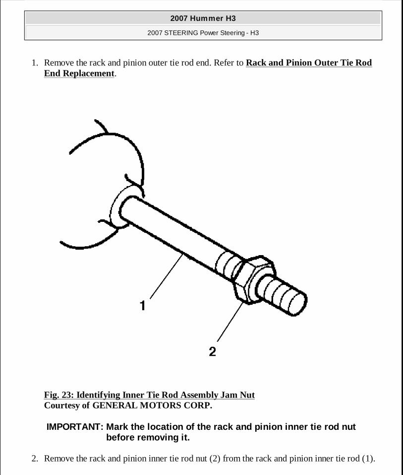
Fig. 23: Identifying Inner Tie Rod Assembly Jam Nut Courtesy of GENERAL MOTORS CORP.
2. Remove the rack and pinion inner tie rod nut (2) from the rack and pinion inner tie rod (1).
IMPORTANT: Mark the location of the rack and pinion inner tie rod nut before removing it.
2007 Hummer H3
2007 STEERING Power Steering - H3
MY
Sunday, March 29, 2009 9:33:35 PM Page 43 © 2005 Mitchell Repair Information Company, LLC.
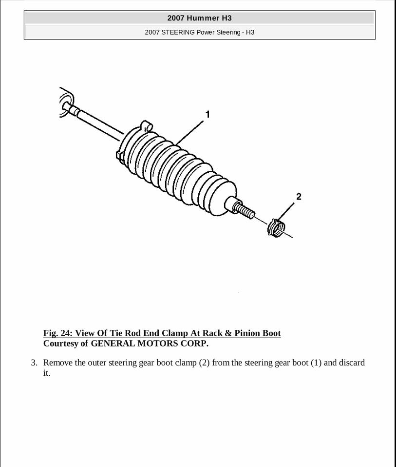
Fig. 24: View Of Tie Rod End Clamp At Rack & Pinion Boot Courtesy of GENERAL MOTORS CORP.
3. Remove the outer steering gear boot clamp (2) from the steering gear boot (1) and discard it.
2007 Hummer H3
2007 STEERING Power Steering - H3
MY
Sunday, March 29, 2009 9:33:35 PM Page 44 © 2005 Mitchell Repair Information Company, LLC.
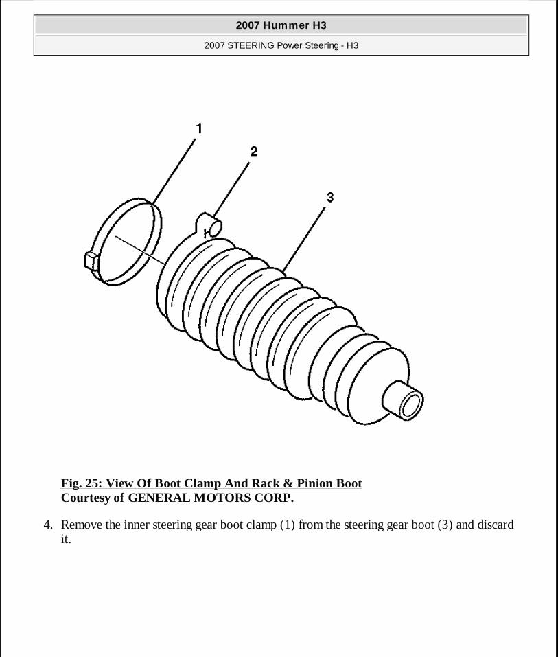
Fig. 25: View Of Boot Clamp And Rack & Pinion Boot Courtesy of GENERAL MOTORS CORP.
4. Remove the inner steering gear boot clamp (1) from the steering gear boot (3) and discard it.
2007 Hummer H3
2007 STEERING Power Steering - H3
MY
Sunday, March 29, 2009 9:33:35 PM Page 45 © 2005 Mitchell Repair Information Company, LLC.
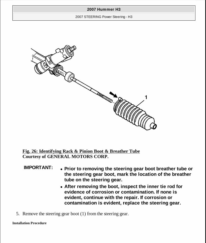
Fig. 26: Identifying Rack & Pinion Boot & Breather Tube Courtesy of GENERAL MOTORS CORP.
5. Remove the steering gear boot (1) from the steering gear.
Installation Procedure
IMPORTANT:� Prior to removing the steering gear boot breather tube or
the steering gear boot, mark the location of the breather tube on the steering gear.
� After removing the boot, inspect the inner tie rod for evidence of corrosion or contamination. If none is evident, continue with the repair. If corrosion or contamination is evident, replace the steering gear.
2007 Hummer H3
2007 STEERING Power Steering - H3
MY
Sunday, March 29, 2009 9:33:35 PM Page 46 © 2005 Mitchell Repair Information Company, LLC.
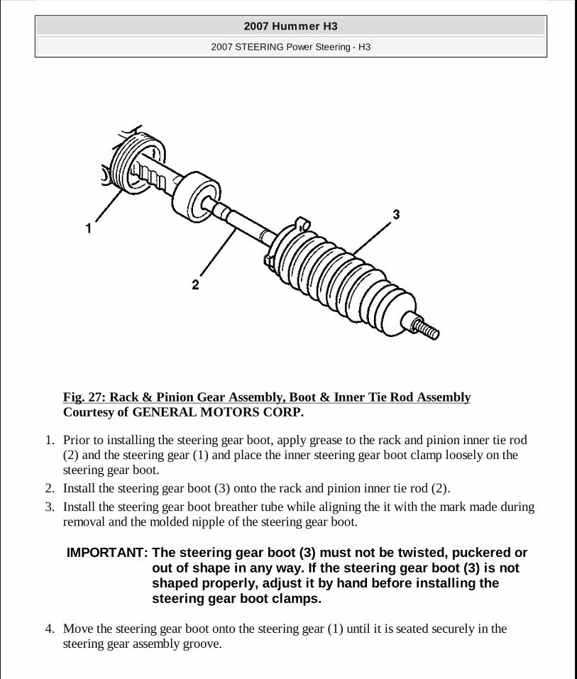
Fig. 27: Rack & Pinion Gear Assembly, Boot & Inner Tie Rod Assembly Courtesy of GENERAL MOTORS CORP.
1. Prior to installing the steering gear boot, apply grease to the rack and pinion inner tie rod (2) and the steering gear (1) and place the inner steering gear boot clamp loosely on the steering gear boot.
2. Install the steering gear boot (3) onto the rack and pinion inner tie rod (2). 3. Install the steering gear boot breather tube while aligning the it with the mark made during
removal and the molded nipple of the steering gear boot.
4. Move the steering gear boot onto the steering gear (1) until it is seated securely in the steering gear assembly groove.
IMPORTANT: The steering gear boot (3) must not be twisted, puckered or out of shape in any way. If the steering gear boot (3) is not shaped properly, adjust it by hand before installing the steering gear boot clamps.
2007 Hummer H3
2007 STEERING Power Steering - H3
MY
Sunday, March 29, 2009 9:33:35 PM Page 47 © 2005 Mitchell Repair Information Company, LLC.
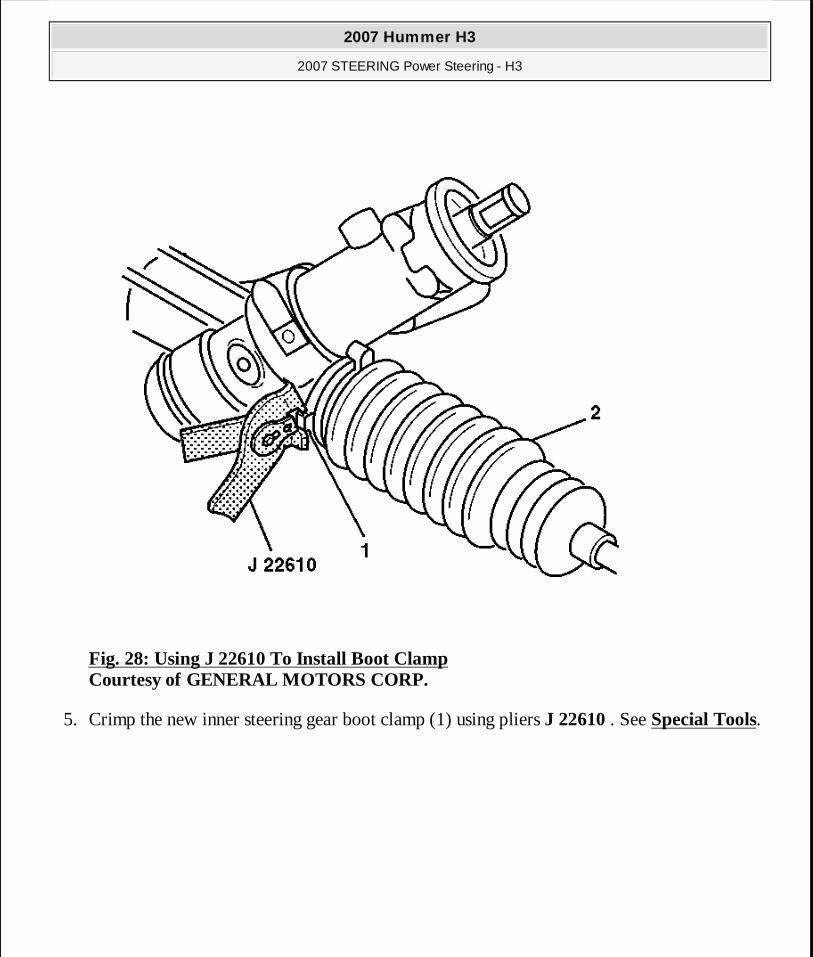
Fig. 28: Using J 22610 To Install Boot Clamp Courtesy of GENERAL MOTORS CORP.
5. Crimp the new inner steering gear boot clamp (1) using pliers J 22610 . See Special Tools.
2007 Hummer H3
2007 STEERING Power Steering - H3
MY
Sunday, March 29, 2009 9:33:35 PM Page 48 © 2005 Mitchell Repair Information Company, LLC.
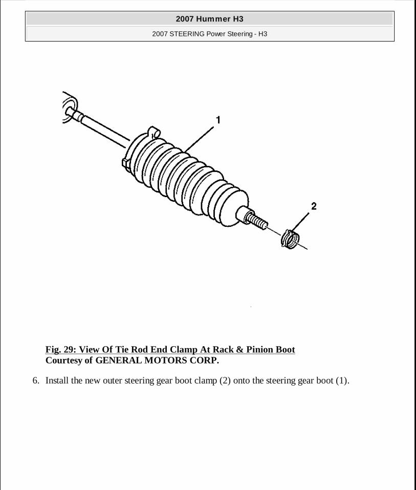
Fig. 29: View Of Tie Rod End Clamp At Rack & Pinion Boot Courtesy of GENERAL MOTORS CORP.
6. Install the new outer steering gear boot clamp (2) onto the steering gear boot (1).
2007 Hummer H3
2007 STEERING Power Steering - H3
MY
Sunday, March 29, 2009 9:33:35 PM Page 49 © 2005 Mitchell Repair Information Company, LLC.
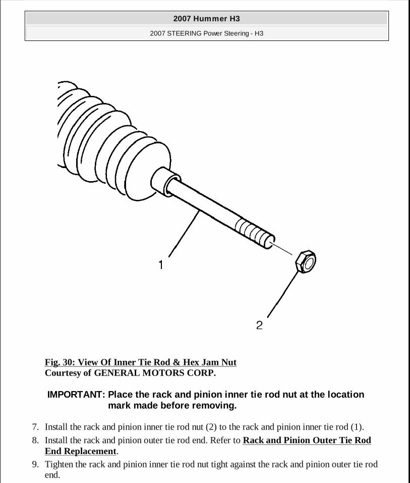
Fig. 30: View Of Inner Tie Rod & Hex Jam Nut Courtesy of GENERAL MOTORS CORP.
7. Install the rack and pinion inner tie rod nut (2) to the rack and pinion inner tie rod (1).
8. Install the rack and pinion outer tie rod end. Refer to Rack and Pinion Outer Tie Rod End Replacement.
9. Tighten the rack and pinion inner tie rod nut tight against the rack and pinion outer tie rod end.
IMPORTANT: Place the rack and pinion inner tie rod nut at the location mark made before removing.
2007 Hummer H3
2007 STEERING Power Steering - H3
MY
Sunday, March 29, 2009 9:33:35 PM Page 50 © 2005 Mitchell Repair Information Company, LLC.
10. Adjust the front toe. Refer to Front Toe Adjustment .
POWER STEERING GEAR INLET AND OUTLET HOSE REPLACEMENT
Tools Required
J 44586 Power Steering Gear Oil Seal Remover/Installer. See Special Tools.
Removal Procedure
1. Remove as much power steering fluid from the power steering fluid reservoir as possible. 2. Place drain pans under the vehicle as needed.
NOTE: Refer to POWER STEERING HOSE DISCONNECTED NOTICE .
2007 Hummer H3
2007 STEERING Power Steering - H3
MY
Sunday, March 29, 2009 9:33:35 PM Page 51 © 2005 Mitchell Repair Information Company, LLC.
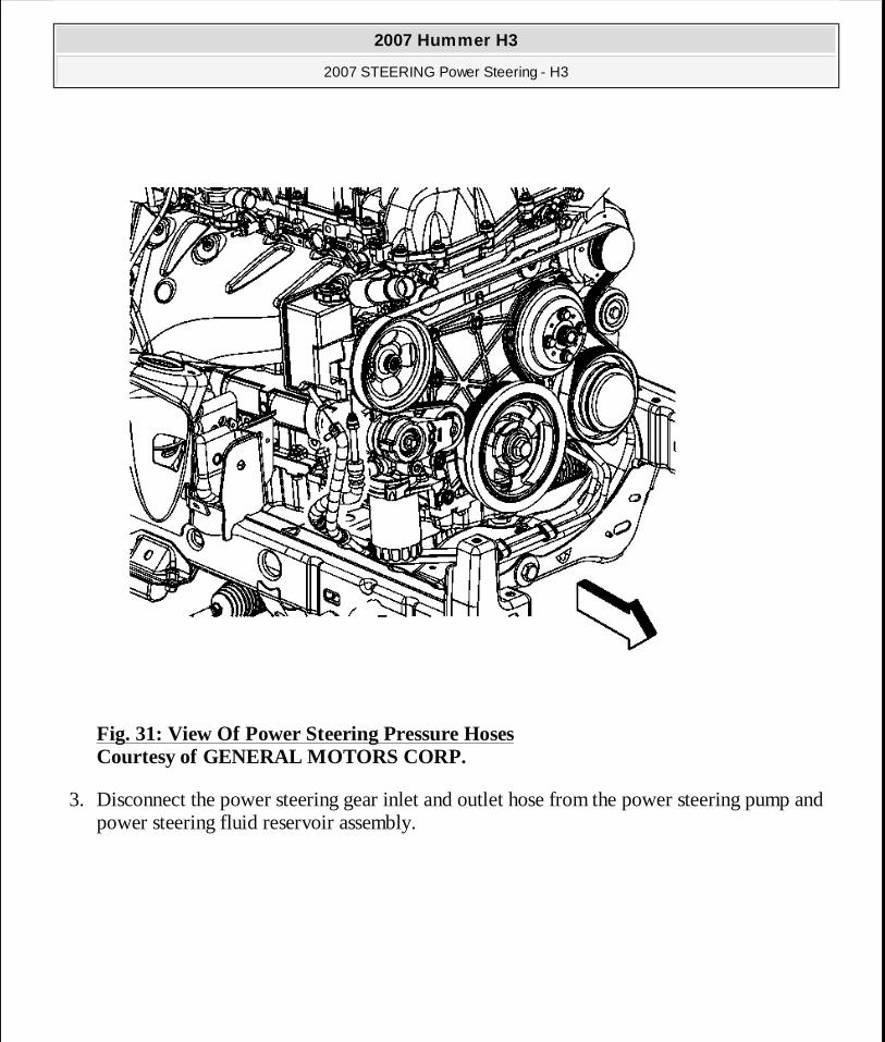
Fig. 31: View Of Power Steering Pressure Hoses Courtesy of GENERAL MOTORS CORP.
3. Disconnect the power steering gear inlet and outlet hose from the power steering pump and power steering fluid reservoir assembly.
2007 Hummer H3
2007 STEERING Power Steering - H3
MY
Sunday, March 29, 2009 9:33:35 PM Page 52 © 2005 Mitchell Repair Information Company, LLC.
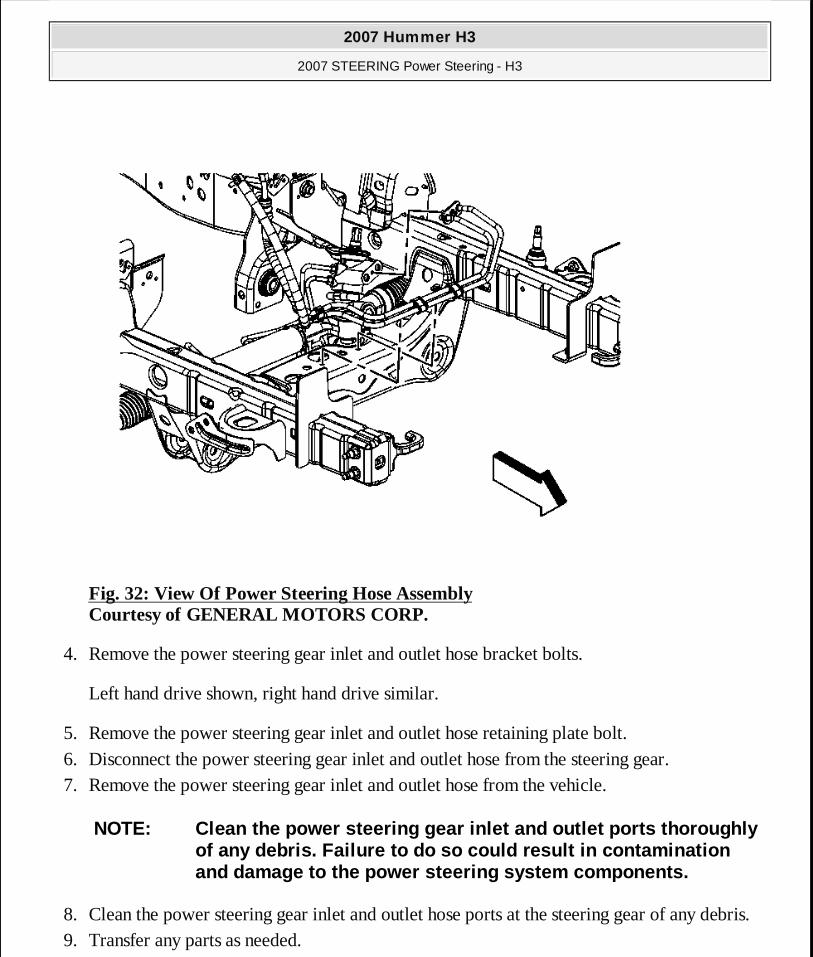
Fig. 32: View Of Power Steering Hose Assembly Courtesy of GENERAL MOTORS CORP.
4. Remove the power steering gear inlet and outlet hose bracket bolts.
Left hand drive shown, right hand drive similar.
5. Remove the power steering gear inlet and outlet hose retaining plate bolt. 6. Disconnect the power steering gear inlet and outlet hose from the steering gear. 7. Remove the power steering gear inlet and outlet hose from the vehicle.
8. Clean the power steering gear inlet and outlet hose ports at the steering gear of any debris. 9. Transfer any parts as needed.
NOTE: Clean the power steering gear inlet and outlet ports thoroughly of any debris. Failure to do so could result in contamination and damage to the power steering system components.
2007 Hummer H3
2007 STEERING Power Steering - H3
MY
Sunday, March 29, 2009 9:33:35 PM Page 53 © 2005 Mitchell Repair Information Company, LLC.
Installation Procedure
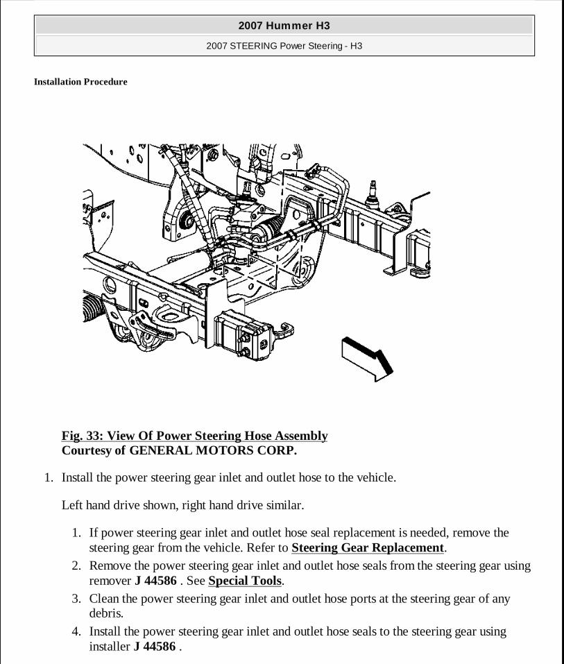
Fig. 33: View Of Power Steering Hose Assembly Courtesy of GENERAL MOTORS CORP.
1. Install the power steering gear inlet and outlet hose to the vehicle.
Left hand drive shown, right hand drive similar.
1. If power steering gear inlet and outlet hose seal replacement is needed, remove the steering gear from the vehicle. Refer to Steering Gear Replacement.
2. Remove the power steering gear inlet and outlet hose seals from the steering gear using remover J 44586 . See Special Tools.
3. Clean the power steering gear inlet and outlet hose ports at the steering gear of any debris.
4. Install the power steering gear inlet and outlet hose seals to the steering gear using installer J 44586 .
2007 Hummer H3
2007 STEERING Power Steering - H3
MY
Sunday, March 29, 2009 9:33:35 PM Page 54 © 2005 Mitchell Repair Information Company, LLC.
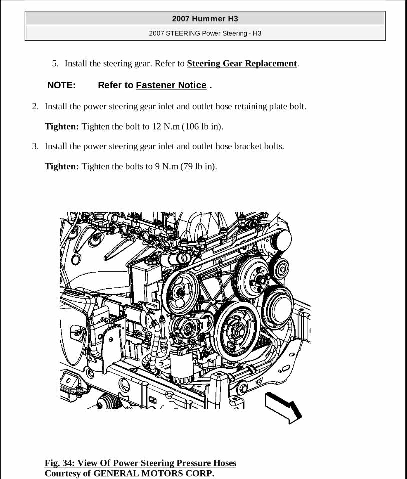
5. Install the steering gear. Refer to Steering Gear Replacement.
2. Install the power steering gear inlet and outlet hose retaining plate bolt.
Tighten: Tighten the bolt to 12 N.m (106 lb in).
3. Install the power steering gear inlet and outlet hose bracket bolts.
Tighten: Tighten the bolts to 9 N.m (79 lb in).
Fig. 34: View Of Power Steering Pressure Hoses Courtesy of GENERAL MOTORS CORP.
NOTE: Refer to Fastener Notice .
2007 Hummer H3
2007 STEERING Power Steering - H3
MY
Sunday, March 29, 2009 9:33:35 PM Page 55 © 2005 Mitchell Repair Information Company, LLC.
4. Connect the power steering gear inlet and outlet hose to the power steering pump and power steering fluid reservoir assembly.
Tighten: Tighten the fitting to 25 N.m (18 lb ft).
5. Clean any excess power steering fluid from the vehicle and remove the drain pans.
6. Fill and bleed the power steering system. Refer to Power Steering System Bleeding.
STEERING GEAR REPLACEMENT
Removal Procedure
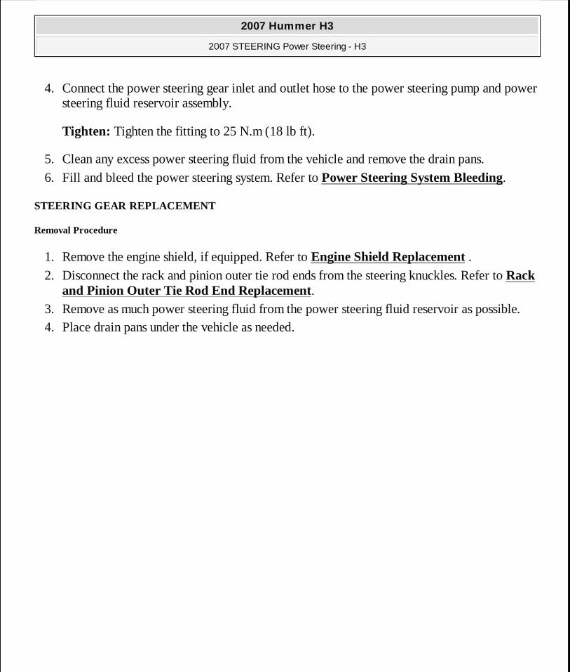
1. Remove the engine shield, if equipped. Refer to Engine Shield Replacement . 2. Disconnect the rack and pinion outer tie rod ends from the steering knuckles. Refer to Rack
and Pinion Outer Tie Rod End Replacement. 3. Remove as much power steering fluid from the power steering fluid reservoir as possible. 4. Place drain pans under the vehicle as needed.
2007 Hummer H3
2007 STEERING Power Steering - H3
MY
Sunday, March 29, 2009 9:33:35 PM Page 56 © 2005 Mitchell Repair Information Company, LLC.
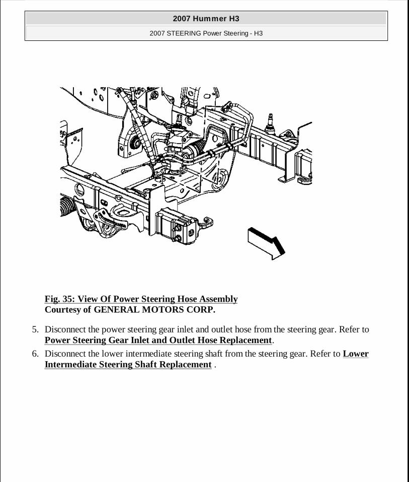
Fig. 35: View Of Power Steering Hose Assembly Courtesy of GENERAL MOTORS CORP.
5. Disconnect the power steering gear inlet and outlet hose from the steering gear. Refer to Power Steering Gear Inlet and Outlet Hose Replacement.
6. Disconnect the lower intermediate steering shaft from the steering gear. Refer to Lower Intermediate Steering Shaft Replacement .
2007 Hummer H3
2007 STEERING Power Steering - H3
MY
Sunday, March 29, 2009 9:33:35 PM Page 57 © 2005 Mitchell Repair Information Company, LLC.
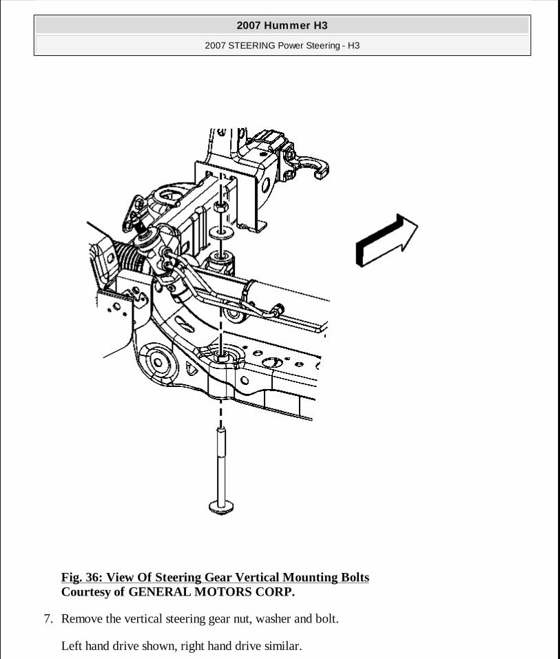
Fig. 36: View Of Steering Gear Vertical Mounting Bolts Courtesy of GENERAL MOTORS CORP.
7. Remove the vertical steering gear nut, washer and bolt.
Left hand drive shown, right hand drive similar.
2007 Hummer H3
2007 STEERING Power Steering - H3
MY
Sunday, March 29, 2009 9:33:35 PM Page 58 © 2005 Mitchell Repair Information Company, LLC.
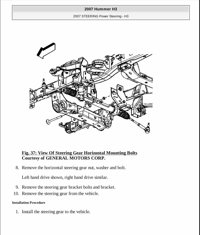
Fig. 37: View Of Steering Gear Horizontal Mounting Bolts Courtesy of GENERAL MOTORS CORP.
8. Remove the horizontal steering gear nut, washer and bolt.
Left hand drive shown, right hand drive similar.
9. Remove the steering gear bracket bolts and bracket. 10. Remove the steering gear from the vehicle.
Installation Procedure
1. Install the steering gear to the vehicle.
2007 Hummer H3
2007 STEERING Power Steering - H3
MY
Sunday, March 29, 2009 9:33:35 PM Page 59 © 2005 Mitchell Repair Information Company, LLC.
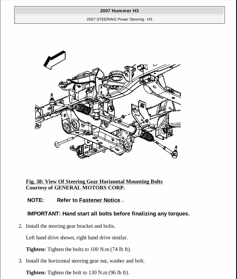
Fig. 38: View Of Steering Gear Horizontal Mounting Bolts Courtesy of GENERAL MOTORS CORP.
2. Install the steering gear bracket and bolts.
Left hand drive shown, right hand drive similar.
Tighten: Tighten the bolts to 100 N.m (74 lb ft).
3. Install the horizontal steering gear nut, washer and bolt.
Tighten: Tighten the bolt to 130 N.m (96 lb ft).
NOTE: Refer to Fastener Notice .
IMPORTANT: Hand start all bolts before finalizing any torques.
2007 Hummer H3
2007 STEERING Power Steering - H3
MY
Sunday, March 29, 2009 9:33:35 PM Page 60 © 2005 Mitchell Repair Information Company, LLC.

Fig. 39: View Of Steering Gear Vertical Mounting Bolts Courtesy of GENERAL MOTORS CORP.
4. Install the vertical steering gear nut, washer and bolt.
Left hand drive shown, right hand drive similar.
2007 Hummer H3
2007 STEERING Power Steering - H3
MY
Sunday, March 29, 2009 9:33:35 PM Page 61 © 2005 Mitchell Repair Information Company, LLC.
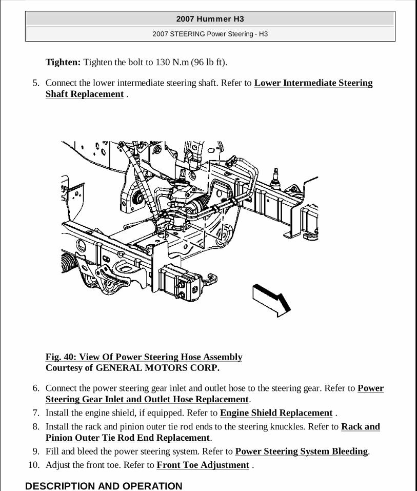
Tighten: Tighten the bolt to 130 N.m (96 lb ft).
5. Connect the lower intermediate steering shaft. Refer to Lower Intermediate Steering Shaft Replacement .
Fig. 40: View Of Power Steering Hose Assembly Courtesy of GENERAL MOTORS CORP.
6. Connect the power steering gear inlet and outlet hose to the steering gear. Refer to Power Steering Gear Inlet and Outlet Hose Replacement.
7. Install the engine shield, if equipped. Refer to Engine Shield Replacement . 8. Install the rack and pinion outer tie rod ends to the steering knuckles. Refer to Rack and
Pinion Outer Tie Rod End Replacement. 9. Fill and bleed the power steering system. Refer to Power Steering System Bleeding.
10. Adjust the front toe. Refer to Front Toe Adjustment .
DESCRIPTION AND OPERATION
2007 Hummer H3
2007 STEERING Power Steering - H3
MY
Sunday, March 29, 2009 9:33:35 PM Page 62 © 2005 Mitchell Repair Information Company, LLC.
POWER STEERING SYSTEM DESCRIPTION AND OPERATION
The hydraulic power steering pump is a constant displacement vane-type pump that provides hydraulic pressure and flow for the power steering gear. The hydraulic power steering pump is belt-driven.
The power steering fluid reservoir holds the power steering fluid and is integral with the power steering pump. The reservoir can be serviced separately from the pump.
This vehicle uses a rack and pinion system.
In the rack and pinion system, the rack and the pinion are the 2 components that convert steering wheel rotation to lateral movement. The steering shaft is attached to the pinion in the steering gear. The pinion rotates with the steering wheel. Gear teeth on the pinion mesh with the gear teeth on the rack. The rotating pinion moves the rack from side to side. The lateral action of the rack pushes and pulls the tie rods in order to change the direction of the vehicle's front wheels.
The power steering pressure hose connects the power steering pump fitting to the power steering gear and allows pressurized power steering fluid to flow from the pump to the gear.
The power steering return hose returns fluid from the power steering gear back to the power steering fluid reservoir. The power steering return line may contain an integral fin-type or line-type power steering fluid cooler.
In a typical power steering system, a pump generates hydraulic pressure, causing fluid to flow, via the pressure hose, to the steering gear valve assembly. The steering gear valve assembly regulates the incoming fluid to the right and left chambers in order to assist in right and left turns.
Turning the steering wheel activates the valve assembly, which applies greater fluid pressure and flow to 1 side of the steering gear piston and lower pressure and flow to the other side of the piston. The pressure assists the movement of the gear piston. Tie rods transfer this force to the front wheels, which turn the vehicle right or left.
SPECIAL TOOLS AND EQUIPMENT
SPECIAL TOOLS
Special Tools Illustration Tool Number/Description
2007 Hummer H3
2007 STEERING Power Steering - H3
MY
Sunday, March 29, 2009 9:33:35 PM Page 63 © 2005 Mitchell Repair Information Company, LLC.
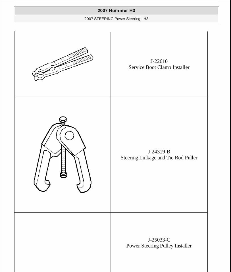
J-22610 Service Boot Clamp Installer
J-24319-B Steering Linkage and Tie Rod Puller
J-25033-C Power Steering Pulley Installer
2007 Hummer H3
2007 STEERING Power Steering - H3
MY
Sunday, March 29, 2009 9:33:35 PM Page 64 © 2005 Mitchell Repair Information Company, LLC.
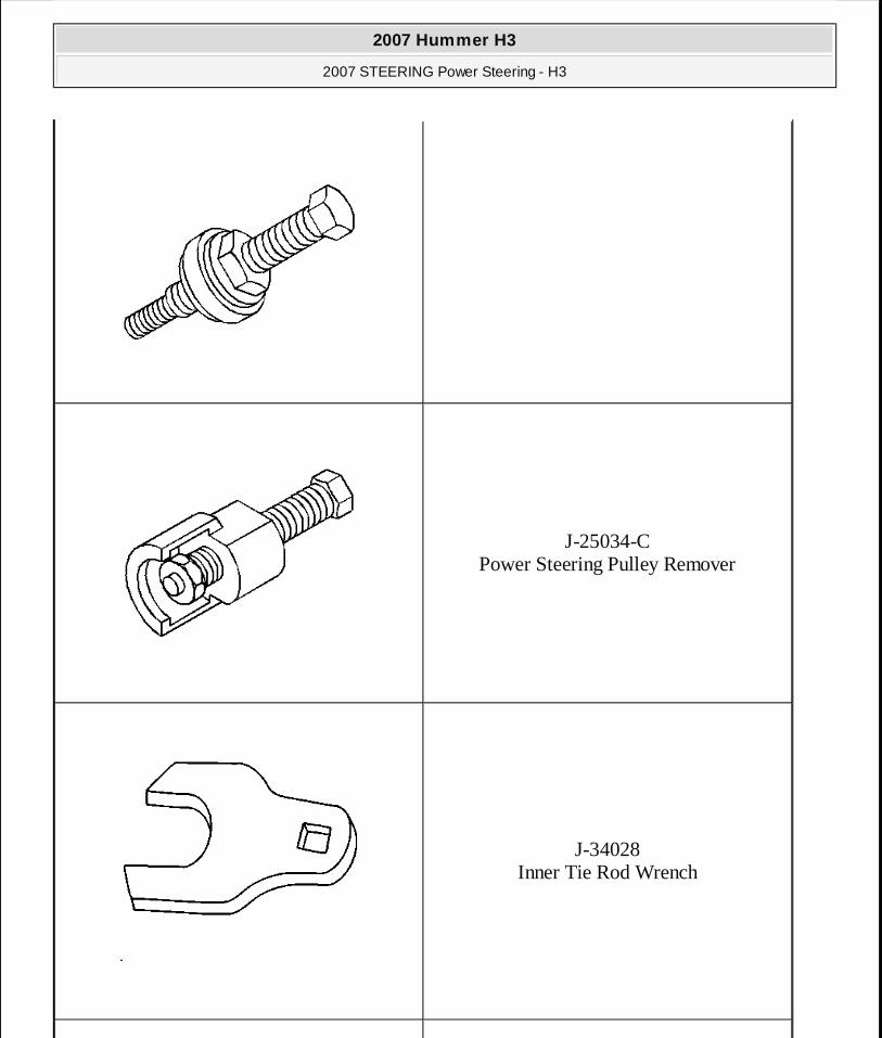
J-25034-C Power Steering Pulley Remover
J-34028 Inner Tie Rod Wrench
2007 Hummer H3
2007 STEERING Power Steering - H3
MY
Sunday, March 29, 2009 9:33:35 PM Page 65 © 2005 Mitchell Repair Information Company, LLC.
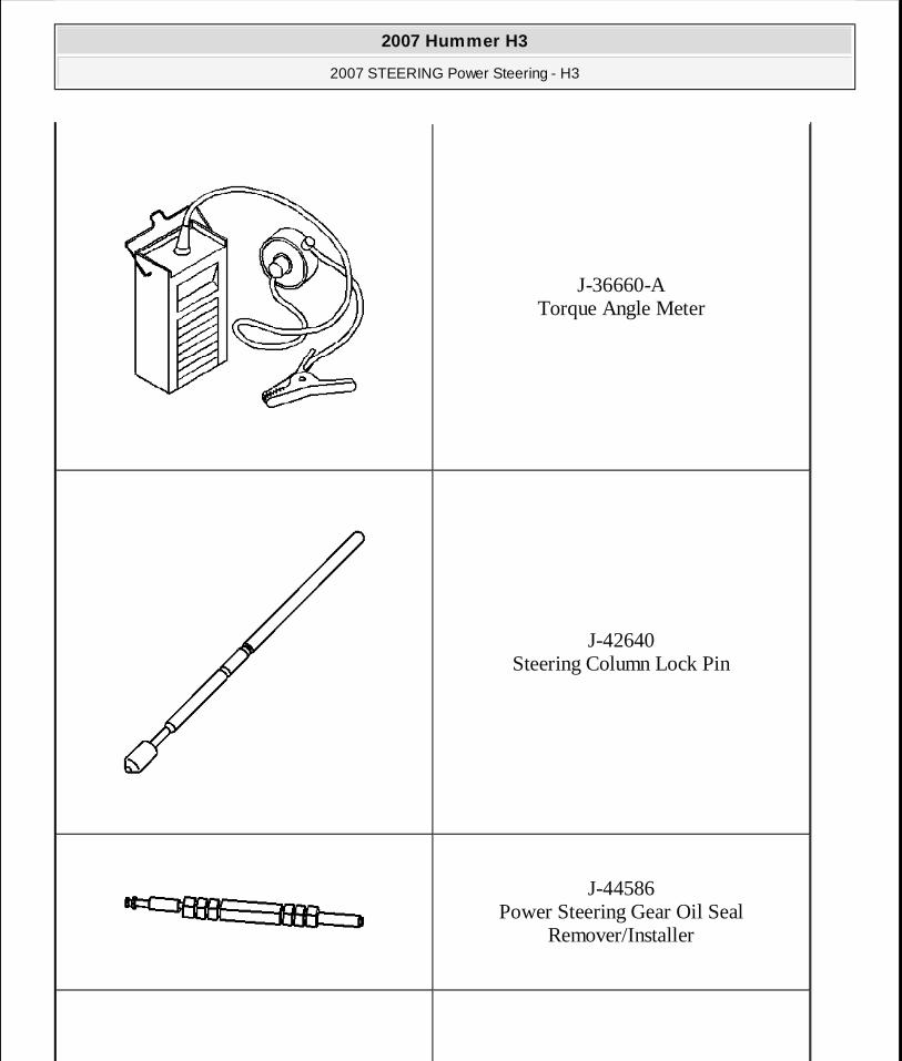
J-36660-A Torque Angle Meter
J-42640 Steering Column Lock Pin
J-44586 Power Steering Gear Oil Seal
Remover/Installer
2007 Hummer H3
2007 STEERING Power Steering - H3
MY
Sunday, March 29, 2009 9:33:35 PM Page 66 © 2005 Mitchell Repair Information Company, LLC.
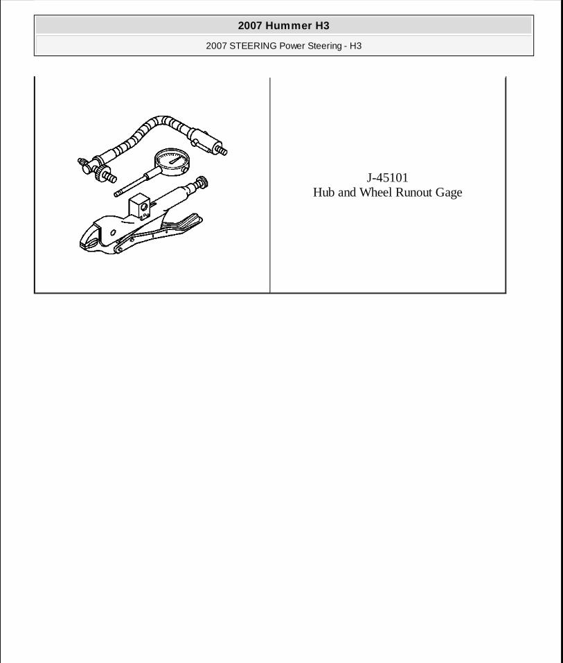
J-45101 Hub and Wheel Runout Gage
2007 Hummer H3
2007 STEERING Power Steering - H3
MY
Sunday, March 29, 2009 9:33:36 PM Page 67 © 2005 Mitchell Repair Information Company, LLC.