2007 ASME Power Conference Troubleshooting Condenser Vacuum Issues At North Omaha Station Unit 1...
26
-
Upload
komandur-sunder-raj-pe -
Category
Presentations & Public Speaking
-
view
207 -
download
0
Transcript of 2007 ASME Power Conference Troubleshooting Condenser Vacuum Issues At North Omaha Station Unit 1...
∗Examine Background/Operating History of Low Vacuum Issues at North Omaha Station Unit 1 (NOS 1) During 2004-2006
∗Describe Troubleshooting Methodology & Proposed Remedies
∗Discuss Implemented/Follow-Up Actions

∗NOS 1 – 60 Mwe Nominal Rating @ 1.0 in.HgA ∗GE Turbine Generator – 1400 Psig,
1000 F/1000 F ∗Foster-Wheeler Condenser – Once-
Through Cooling - Missouri River ∗Retubed in 70s with SS ∗Hogging/Holding SJAEs


∗Each First Stage Element Designed to Handle (12.5 Scfm) 179 lb/hr of Air/Water Vapor Mixture – 56 lb/hr of Dry Air & 123 lb/hr of Water Vapor at 71.5 F & 1.0 in.HgA ∗Design Motive Steam Pressure 400
Psig (Main Steam Reduced from 1400 Psig) ∗Expected Operating Air Inleakage
at Full Load 2 to 3 Scfm & DO Level < 7 PPB
∗Designed to Handle (200 Scfm) 900 lb/hr of Dry Air 10.0 in.HgA for Initial Evacuation of Condenser Shell (~ 30 Mins.) ∗Design Motive Steam Pressure
400 Psig (Auxiliary Steam)

∗Intercondenser ~ 290 Tubes ∗Aftercondenser ~ 101 Tubes ∗Main Condensate Used for
Cooling ∗Split in Flow 74%/26%

∗2003 ∗Low Vacuum – Calcium Carbonate Deposits ∗Scale Removed to Improve Performance
∗2004 ∗High Air Inleakages, Low Vacuum,
Instabilities ∗Several Condenser Upsets, Unit Trip ∗Leakage Immeasurable (Exceeded Scale of
20 Scfm) ∗Leakage Locations - Bearing Vent, Rupture
Disc, Manway Covers

∗2005 ∗N2 Bearing Water Seals Repaired During
Outage (Major Source of Leakage) ∗ Leaking Intercondenser Tubes Plugged ∗Main Condenser Tubes Scraped ∗ Post-Outage Data Showed Marked
Improvement ∗ Following Vacuum Upset in June, Hogging
Ejector Placed in Service to Stabilize Unit ∗Helium Testing in July Indicated High Inleakage
at N2 Bearing ∗ Leakage Fixed - Unit Continued to Operate
with Degraded Vacuum

∗2006 ∗Unit Trip in February – Low Vacuum ∗Motive Steam Pressure >800 Psig, 58
Mwe ∗Unit Load Maintained at 40 Mwe with
Hogging Ejector, One Set of First Stage & Second Stage Holding Ejector Elements in Service
∗Motive Steam Pressure at 600 Psig ∗Attempt to Remove Hogging SJAE from
Service Unsuccessful – Rapid Decrease of Air-Removal Capability of Holding SJAE
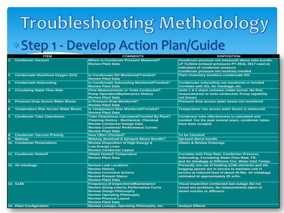
∗Step 1 - Develop Action Plan/Guide 1. Condenser Vacuum Where is Condenser Pressure Measured? Condenser pressure not measured above tube bundle.
Review Plant Data LP Turbine exhaust pressures PT-3516, 3517 used asindicators of condenser pressureCondenser pressure not routinely trended
2. Condensate Dissolved Oxygen (DO) Is Condensate DO Monitored/Trended? Plant chemistry monitors condensate DO.Review Plant Data
3. Condensate Subcooling Is Condensate Subcooling Monitored/Trended? Condensate subcooling not monitored or trendedReview Plant Data Correlate with DO, Air Inleakage, etc.
4. Circulating Water Flow Rate Flow Measurements or Tests Conducted? Units 1 & 2 share common intake tunnel. No flowPump Operation/Maintenance History measurements or tests conducted. Pump capabilityReview Plant Data not known
5. Pressure Drop Across Water Boxes Is Pressure Drop Monitored? Pressure drop across water boxes not monitoredReview Plant Data
6. Temperature Rise Across Water Boxes Is Temperature Rise Monitored/Trended? Temperature rise across water boxes is measured.Review Plant Data
7. Condenser Tube Cleanliness Tube Cleanliness Calculated/Trended By Plant? Condenser tube effectiveness is calculated andCleaning History - Mechanical, Chemical trended. For the past several years, condenser tubesReview Condenser Design Data have been scraped.Review Condenser Performance CurvesReview Plant Data
8. Condenser Vacuum Priming How Often Checked? To be Checked9. Makeup Makeup Atomized & Sprayed Above Bundle? Sprayed above bundle10. Condenser Penetrations Review Disposition of High-Energy & Obtain & Review Drawings
Low-Energy LinesReview Condenser Layout
11. Condenser Hotwell Obtain Hotwell Temperature Correlate with Flow Rate, Condenser Pressure,Review Plant Data Subcooling, Circulating Water Flow Rate, TR,
and Air Inleakage at Different Circ. Water Inlet Temps.12. Air Inleakage Review Leak Locations Presently one set of holding SJAE elements and the
Review History hogging ejector are in service to maintain unit inReview Corrective Actions service at reduced load of about 40 Mw. Air inleakageReview Present Status estimated at approximately 25 scfm.Review Plant Data
13. SJAE Frequency of Inspections/Maintenance Visual inspection conducted last outage did notReview Sizing criteria, Performance Curve reveal any problems. No measurements taken ofReview Design Philosophy steam nozzles or diffusers.Review Operating PhilosophyReview Physical LayoutReview Plant Data
14. Plant Configuration Review Lineups, Operating Philosophy, etc. Analyze Effects
COMMENTS DISPOSITIONITEM

∗Step 2 - Predict Condenser Performance at Different Loads, CF

∗Step 3 – Analyze 2004-2006 Condenser Data ∗September 2004 Data ∗Condenser Pressure 2.0 in.HgA at 69.0 F and
60 Mwe ∗Expected Pressure 1.5 in.HgA for 85% CF and
1.6 in.HgA for 60% CF ∗Due to High Air Inleakage, Estimate of Tube
Fouling 0.1 – 0.2 in.HgA and Air Inleakage/Blanketing 0.4 – 0.5 in.HgA
∗March 2005 Data ∗Condenser Pressure 2.0 in.HgA at 69.0 F and
60 Mwe

∗Step 3 – Analyze 2004-2006 Condenser Data ∗March 2005 Data ∗Condenser Pressure of 1.0 in.HgA at 45.0 F
and 60 Mwe ∗Expected Condenser Pressure 0.74 in.HgA for
85% CF and 0.88 in.HgA for 60% CF ∗Since Condenser Tubes Had Been Scraped in
Jan. 2005, Tube Fouling Estimate – 0.1 in.HgA, Air Inleakage/Blanketing 0.1 – 0.2 in.HgA
∗February 16, 2006 Data ∗Condenser Pressure of 2.0 in.HgA at 51.0 F
and 60 Mwe

∗Step 3 – Analyze 2004-2006 Condenser Data ∗February 16, 2006 Data ∗Expected Condenser Pressure of 0.8 in.HgA
for 85% CF and 0.9 in.HgA at 60% CF ∗Due to Excessive Air Inleakage, Estimate of
Tube Fouling 0.1 – 0.2 in.HgA and Up to 1.0 in.HgA due to Air Inleakage/Blanketing
∗March 2-3, 2006 Data ∗Condenser Pressure of 1.4 in.HgA at 51.0 F
and 60 Mwe ∗Expected Condenser Pressure of 0.8 in.HgA
for 85% CF and 0.9 in.HgA at 60% CF

∗Step 3 – Analyze 2004-2006 Condenser Data ∗March 2-3, 2006 Data ∗With Unit Still Operating with High Air
Inleakage, Estimate of Tube Fouling 0.1 – 0.2 in.HgA, Up to 0.5 in.HgA due to Air Inleakage/Blanketing
∗Step 4 – Prepare Findings/Conclusions ∗Unit Trip on Feb. 16, 2006 Suggested Air
Inleakage > 25 Scfm
∗Step 4 – Prepare Findings/Conclusions ∗Reduction in Load from 60 Mwe to 40 Mwe
Increased Potential for Air Inleakage/DO ∗Combination of Hogging/Holding SJAE
Created Instabilities ∗Motive Steam Pressures up to Double
Design Pressures Resulted in up to Double Steam Consumption/Water Vapor Loadings
∗Possible Compromise of Intercondenser/Aftercondenser Performance

∗Locate & Fix All Sources of Leakage – Comprehensive Leakage Monitoring Program
∗Scrape Condenser Tubes to Restore Tube Cleanliness
∗Inspect SJAE System for Wear/Tear ∗Replace Steam Nozzles, Ejector Bodies
if Throat Areas Exceed 110% of Design ∗Retube Intercondenser/Aftercondenser
if Plugged Tubes Exceed 10%

∗Operate with Only One Set of First Stage/Second Stage Elements Under Normal Conditions
∗Maintain Motive Steam Pressures at Design Value of 400 Psig
∗Do Not Operate with Both Holding/Hogging Ejectors in Service for Continuous/Extended Periods
∗Instrument Condenser/SJAE System to Monitor Critical Parameters

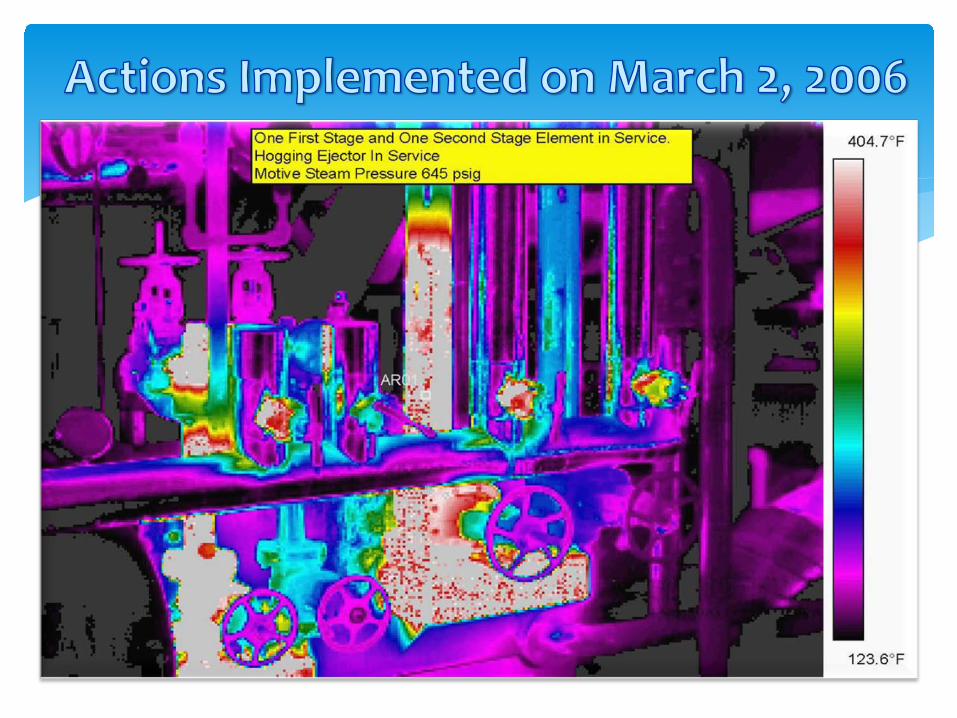
∗At 60 Mwe and Motive Steam Pressure of 645 Psig, Second Stage Spare SJAE Element Placed in Service
∗Hogging Ejector Removed from Service ∗Load Raised to 43 Mwe and
Subsequently to 60 Mwe ∗Motive Steam Pressure Lowered to 400
Psig ∗Loop Seal from Intercondenser Re-
Established


∗ Intercondenser/Aftercondenser Tube Bundles Eddy-Current Tested
∗ Large Scale Tube Wall Reduction – 13 Tubes Plugged
∗ Leakage Across Partition Plate – Exact Location Could Not be Identified
∗N2 Bearing Vent Line Flange Sealed ∗ Pinhole Leaks in Extraction Steam Line Repaired ∗Main Condenser Tubes Scraped ∗ Leak in Main Steam Stop Valve After-Seat Drain
Line Fixed (Estimated Air Inleakage of 7-8 Scfm)