2007-2011 MULTIPLE AKES AND ODELS E LECTRONIC RUISE …
12
2007-2011 MULTIPLE MAKES AND MODELS ELECTRONIC CRUISE CONTROL KIT MIXED TRANSMISSION COMPATIBILITY PART NUMBER: 250-1855 Form #5221, Rev. H, 06-15-12 General Applicability Kit Contents Contents of Hardware Bag Qty Description 8 Wire Zip Ties This cruise control was tested and verified on: 07-11 Honda Fit, Civic with ABS (AT/MT) 09-Nissan Cube with ABS (AT/MT) This cruise control may not function correctly on unverified vehicles. See www.rostra.com for vehicle compatibility. Safety Tools Gloves, Safety Glasses Special Tools Volt-Ohm Meter Installation Tools Trim Removal Tool Side cutter To cut wire ties Drill Bit or Knockout Punch 9.5mm or 3/8” (for switch) 10mm wrench Soldering Tool Special Chemicals Item Qty Description Service Part # 1 1 Cruise Control Module 250-2786 2 1 Switch Harness 250-2760 3 1 Main Wiring Harness 250-2759 4 1 Pedal Interface Harness 250-2771/ 250-2815 5 1 Hardware Kit 250-2767 6 1 Control Switch 250-3742 Note: Vehicles without ABS are not compatible with this cruise control. Conflicts Legend STOP STOP: Damage to the vehicle may occur. Do not proceed until process has been complied with. OPERATOR SAFETY: Use caution to avoid risk of injury CRITICAL PROCESS: Proceed with caution to ensure a quality installation. GENERAL PROCESS: This highlights specific processes to ensure a quality installation. TOOLS & EQUIPMENT: This calls out the specific tools and equipment required for this process Recommended Tools 1 3 2 4 5 6 WARNING: DO NOT USE HAND-HELD 2-WAY TRANSCEIVERS INSIDE YOUR VEHICLE WHILE DRIVING WITH CRUISE CONTROL ENGAGED. WHEN TRANSMITTING FROM INSIDE THE CAR, 2-WAY RADIOS THAT OPERATE IN THE 25 MHz - 700 MHz FREQUENCY RANGE WITH MORE THAN 2.0 WATTS OF POWER CAN PRODUCE ELECTROMAGNETIC INTERFERENCE THAT COULD INTERFERE WITH THE OPERATION OF CRUISE AND THROTTLE CONTROLS RESULTING IN VEHICLE "LIMP MODE". Use of cell phones will not interfere with these controls. DUE TO SENSITIVE NATURE OF SIGNALS USED FOR THIS PRODUCT ALL NON PLUG AND PLAY CONNECTIONS MUST BE SOLDERED. FAILURE TO COMPLY WITH THIS REQUIREMENT WILL VOID WARRANTY.
Transcript of 2007-2011 MULTIPLE AKES AND ODELS E LECTRONIC RUISE …

2007-2011 MULTIPLE MAKES AND MODELS ELECTRONIC CRUISE CONTROL KIT MIXED TRANSMISSION COMPATIBILITY PART NUMBER: 250-1855
Form #5221, Rev. H, 06-15-12
General Applicability
Kit Contents
Contents of Hardware Bag Qty Description
8 Wire Zip Ties
This cruise control was tested and verified on: 07-11 Honda Fit, Civic with ABS (AT/MT) 09-Nissan Cube with ABS (AT/MT) This cruise control may not function correctly on unverified vehicles. See www.rostra.com for vehicle compatibility.
Safety Tools
Gloves, Safety Glasses
Special Tools
Volt-Ohm Meter
Installation Tools
Trim Removal Tool Side cutter To cut wire ties Drill Bit or Knockout Punch 9.5mm or 3/8” (for switch) 10mm wrench Soldering Tool
Special Chemicals
Item Qty Description Service Part # 1 1 Cruise Control Module 250-2786 2 1 Switch Harness 250-2760 3 1 Main Wiring Harness 250-2759 4 1 Pedal Interface Harness 250-2771/ 250-2815 5 1 Hardware Kit 250-2767 6 1 Control Switch 250-3742
Note: Vehicles without ABS are not compatible with this cruise control.
Conflicts
Legend
STOPSTOP: Damage to the vehicle may occur. Do not proceed until process has been complied with.
OPERATOR SAFETY: Use caution to avoid risk of injury
CRITICAL PROCESS: Proceed with caution to ensure a quality installation.
GENERAL PROCESS: This highlights specific processes to ensure a quality installation.
TOOLS & EQUIPMENT: This calls out the specific tools and equipment required for this process
Recommended Tools
1
3 2 4
5
6
WARNING: DO NOT USE HAND-HELD 2-WAY TRANSCEIVERS INSIDE YOUR VEHICLE WHILE
DRIVING WITH CRUISE CONTROL ENGAGED. WHEN TRANSMITTING FROM INSIDE THE CAR, 2-WAY RADIOS THAT OPERATE IN THE 25 MHz - 700 MHz FREQUENCY RANGE WITH MORE THAN 2.0 WATTS OF POWER CAN PRODUCE ELECTROMAGNETIC INTERFERENCE THAT COULD INTERFERE WITH THE OPERATION OF CRUISE AND THROTTLE CONTROLS RESULTING IN VEHICLE "LIMP MODE". Use of cell phones will not interfere with these controls. DUE TO SENSITIVE NATURE OF SIGNALS USED FOR THIS PRODUCT ALL NON PLUG AND PLAY CONNECTIONS MUST BE SOLDERED. FAILURE TO COMPLY WITH THIS REQUIREMENT WILL VOID WARRANTY.

2007-2011 MULTIPLE MAKES AND MODELS ELECTRONIC CRUISE CONTROL KIT MIXED TRANSMISSION COMPATIBILITY PART NUMBER: 250-1855
Form #5221, Rev. H, 06-15-12
Connect to the accelerator pedal
VSS PIN 6 WHITE
Behind Junction Box
PUR
VSS
07-11 HONDA CIVIC

2007-2011 MULTIPLE MAKES AND MODELS ELECTRONIC CRUISE CONTROL KIT MIXED TRANSMISSION COMPATIBILITY PART NUMBER: 250-1855
Form #5221, Rev. H, 06-15-12
Connect to the accelerator pedal
PUR
VSS
07-08 HONDA FIT
Junction Box
PIN 7 GRAY/ RED

2007-2011 MULTIPLE MAKES AND MODELS ELECTRONIC CRUISE CONTROL KIT MIXED TRANSMISSION COMPATIBILITY PART NUMBER: 250-1855
Form #5221, Rev. H, 06-15-12
Splice & Solder Direction
Cruise Harness Color Vehicle Wire
CONNECTOR RED LIGHT BLUE PIN6
CONNECTOR WHITE ORANGE PIN 3
HARNESS YELLOW LIGHT BLUE PIN 6
HARNESS GREEN ORANGE PIN 3
09- FIT CONNECTIONS
WHT
RED
GRN
YEL
PUR
Cut wires at pins 3 and 6 of the accelerator pedal harness and solder connections using the chart below:
09- HONDA FIT
VSS
PIN 38 GRAY
Junction Box
Pin 6
Pin 3
Connect to the accelerator pedal

2007-2011 MULTIPLE MAKES AND MODELS ELECTRONIC CRUISE CONTROL KIT MIXED TRANSMISSION COMPATIBILITY PART NUMBER: 250-1855
Form #5221, Rev. H, 06-15-12
Splice & Solder Direction
Cruise Harness Color Vehicle Wire
CONNECTOR RED GREEN PIN 6
CONNECTOR WHITE BROWN PIN 3
HARNESS YELLOW GREEN PIN 6
HARNESS GREEN BROWN PIN 3
CUBE CONNECTIONS
WHT
RED
GRN
YEL
PUR
09- NISSAN CUBE
Pin 6
Pin 3
Cut wires at pins 3 and 6 of the accelerator pedal harness and solder connections using the chart below:
Connect to the accelerator pedal
VSS
Antilock Brake Module
YELLOW
NOTE: YELLOW WIRE WILL BE ENTWINED WITH A BROWN WIRE
2007-2011 MULTIPLE MAKES AND MODELS ELECTRONIC CRUISE CONTROL KIT MIXED TRANSMISSION COMPATIBILITY PART NUMBER: 250-1855
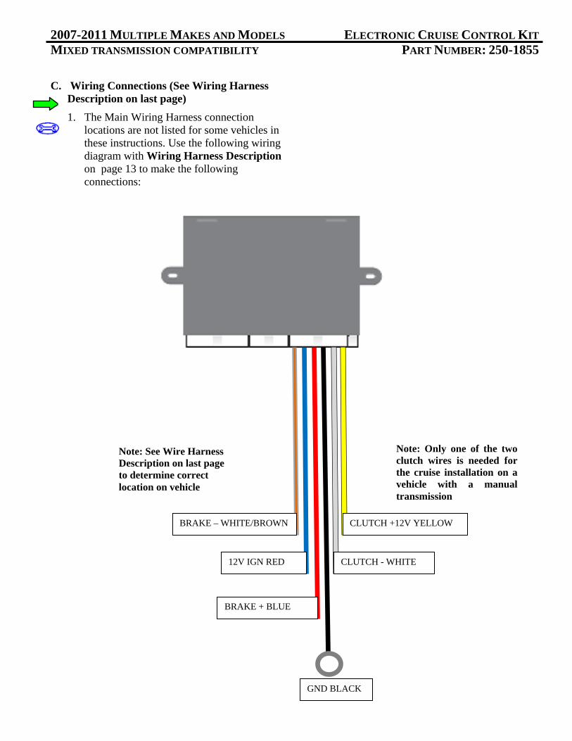
C. Wiring Connections (See Wiring Harness Description on last page)
1. The Main Wiring Harness connection locations are not listed for some vehicles in these instructions. Use the following wiring diagram with Wiring Harness Description on page 13 to make the following connections:
Note: Only one of the two clutch wires is needed for the cruise installation on a vehicle with a manual transmission
Cruise Module
12V IGN RED
BRAKE + BLUE
BRAKE – WHITE/BROWN
GND BLACK
Note: See Wire Harness Description on last page to determine correct location on vehicle
CLUTCH +12V YELLOW
CLUTCH - WHITE
2007-2011 MULTIPLE MAKES AND MODELS ELECTRONIC CRUISE CONTROL KIT MIXED TRANSMISSION COMPATIBILITY PART NUMBER: 250-1855
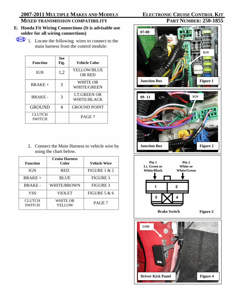
E. Honda Fit Wiring Connections (It is advisable use solder for all wiring connections)
1. Locate the following wires to connect to the main harness from the control module:
2. Connect the Main Harness to vehicle wire by using the chart below.
Function Cruise Harness
Color Vehicle Wire
IGN RED FIGURE 1 & 2
BRAKE + BLUE FIGURE 3
BRAKE - WHITE/BROWN FIGURE 3
VSS VIOLET FIGURE 5 & 6
CLUTCH SWITCH
WHITE OR YELLOW PAGE 7
Function See Fig. Vehicle Color
IGN 1,2 YELLOW/BLUE
OR RED
BRAKE + 3 WHITE OR
WHITE/GREEN
BRAKE - 3 LT.GREEN OR WHITE/BLACK
GROUND 4 GROUND POINT
CLUTCH SWITCH PAGE 7
GND
Driver Kick Panel Figure 4
Brake Switch
Pin 1 Lt. Green or White/Black
Figure 3
Pin 2 White or
White/Green
IGN
Figure 2 Junction Box
09- 11
07-08
IGN
Figure 1 Junction Box

2007-2011 MULTIPLE MAKES AND MODELS ELECTRONIC CRUISE CONTROL KIT MIXED TRANSMISSION COMPATIBILITY PART NUMBER: 250-1855
F. 07-11 Honda Civic Wiring Connections (It is advisable use solder for all wiring connections)
1. Locate the following wires to connect to the main harness from the control module:
2. Connect the Main Harness to vehicle wire by using the chart below:
Function See Fig. Vehicle Color
IGN 1 RED
BRAKE + 2 WHITE
BRAKE - 2 LT. GREEN
GROUND 3 GROUND POINT
CLUTCH SWITCH PAGE 5
Function Cruise Harness
Color Vehicle Wire
IGN RED RED
BRAKE + BLUE WHITE
BRAKE - WHITE/BROWN LT. GREEN
GROUND BLACK GROUND
POINT
CLUTCH SWITCH
WHITE OR YELLOW PAGE 5
IGN
Figure 1
Brake Switch
Pin 1 Lt. Green
Figure 2
Pin 2 White
GND
Driver Kick Panel Figure 3
Junction Box

2007-2011 MULTIPLE MAKES AND MODELS ELECTRONIC CRUISE CONTROL KIT MIXED TRANSMISSION COMPATIBILITY PART NUMBER: 250-1855
G. Install Control Switch
1. Use the lever wedges on the Control Switch at an angle template to drill a 3/8” or 9.5mm hole in the lower shroud of the steering column cover. Position lock-washers as shown. Figure 1
2. Apply nut and position Control Switch for driver’s best view.
3. Assemble (2) 3-pin connectors from the sack parts to the mating wire colors on the Control Switch Harness. Use the diagram to mate the module harness to switch harness. Figure 2
4. Route the assembled Control Switch Harness to the mating connector of the Cruise Control module.
5. Secure the Control Switch Harness with zip ties away from moving parts.
H. Testing
1. Reconnect negative battery cable and torque to 35 in*lbs. Reenter anti-theft radio codes.
2. Turn ignition on. Apply the on/off button of Cruise Control Switch.
K. Reassembly
1. Reinstall all removed pieces taking care to ensure harnesses and wiring connections are properly secured.
2. Make sure all harnesses are not pinched or bound by trim pieces
Figure 1
From Module From Switch
Figure 2
Switch Installed
Figure 3

2007-2011 MULTIPLE MAKES AND MODELS ELECTRONIC CRUISE CONTROL KIT MIXED TRANSMISSION COMPATIBILITY PART NUMBER: 250-1855
Section II - Wiring Diagram
Green 4 volts Ignition
White 4 volts Ignition
Yellow 2 volts Ignition
Red 2 volts Ignition
-
Pedal Interface Harness Voltages with pedal fully depressed
.75 volts Ignition
.35 volts Ignition
Pedal Interface Harness Voltages with pedal not depressed

2007-2010 MULTIPLE MAKES AND MODELS ELECTRONIC CRUISE CONTROL KIT MIXED TRANSMISSION COMPATIBILITY PART NUMBER: 250-1855
Function Color Results Fault Conditions
Ignition Red +12V when switched on and +0V when switched off. Ignition must be greater than +10V while cranking vehicle.
No power, voltage drop, or intermittent connection will cause Loss of pedal or “Limp Mode” condition.
Brake positive +
Blue “Hot” side of brake switch. +12V all the time.
Cruise will not function if this connection is not installed correctly.
Brake negative -
Brown/White “Cold” side of Brake switch. Zero (0) resistance to ground when brake is not pressed. +12V when brake is pressed.
Cruise will not function if this connection is not installed correctly. If connection is good, and there is a high resistance to ground, a 5 terminal relay will be required to complete installation. See diagram below.
Ground Black Lowest resistance to ground closest to zero (0) ohms as possible. Use a vehicle ground point where other ground wires are connected to.
A bad ground connection will cause the following conditions: Cruise will not function; Loss of pedal or “Limp Mode” condition.
Clutch (GND triggered)
White Ground active wire at switch when clutch is depressed.
Cruise will not function if wrong wire is connected –OR– Cruise will not disengage when clutch is depressed.
Clutch (+12V triggered)
Yellow +12V active wire at switch when clutch is depressed.
Cruise will not function if wrong wire is connected –OR– Cruise will not disengage when clutch is depressed.
5 Terminal Relay for Brake Switch
86
85
87
87a
30
Ground
Brake -
Not Used
Brown/White of Cruise Harness
Ground

TECHNICAL TIPS
Control Switch Test
1. Be sure terminals are fully inserted a white and black 3pin connectors before performing switch
test.
Yellow/Green wire at control module On/Off: +12 volts press on, O volts press off
Purple/Red wire at control module Set/Coast: +12 volts press and hold set
Purple/Black wire at control module Resume/Acc: +12 volts press and hold resume
Red & Blue wire at black 3pin connector +10‐12 volts
Black wire at black 3pin connector Less than 5 ohms resistance to ground