2007 - 2008 Titan™ Z4800 & Z5200
172
Residential Products 2007 - 2008 Titan™ Z4800 & Z5200 Service Manual
Transcript of 2007 - 2008 Titan™ Z4800 & Z5200

Residential Products
2007 - 2008Titan™ Z4800 & Z5200
Service Manual

This service manual was written expressly for Toro service technicians. The Toro company has made every effort to make the information in this manual complete and correct.
Basic shop safety knowledge and mechanical/electrical skills are assumed. The Table of Contents lists the systems and the related topics covered in this manual.
manufacturer’s service and repair instructions.
The hydrostatic transaxle is a sophisticated piece of machinery. Maintain strict cleanliness control during all stages of
other contamination can severely damage the system.
comments regarding this manual, please contact us at the following address:
The Toro CompanyResidential and Landscape Contractor Service Training Department8111 Lyndale Avenue SouthBloomington, MN 55420
ABOUT THIS MANUAL
Copyright© All Rights Reserved

ABOUT THIS MANUAL
THIS PAGE INTENTIONALLY LEFT BLANK.
i
TABLE OF CONTENTS
SAFETY INFORMATION ........................................................................................................................
............................................................................................................................
SPECIFICATIONS .....................................................................................................................
RPM ......................................................................................................................................... ............................................................................................................................
..................................................................................................Cutting Deck ...................................................................................................................................Dimensions .....................................................................................................................................
.....................................................................................................................
CHASSIS .............................................................................................
......................................................................................................................................Front Caster Fork Bearing Replacement ........................................................................................
Front Caster Fork Bearing Removal ........................................................................................ .....................................................................................
Caster Wheel Assembly Replacement ...........................................................................................Caster Wheel Assembly Removal ............................................................................................
......................................................................................... ................................................................................. ..................................................................................
............................................................................. ................................................................................................. .................................................................................................
.............................................................................................. ................................................................................................................. .................................................................................................................
.............................................................................................................. ...........................
..................................................... ..................................................
ELECTRICAL ............................................................................................................................
..................................................................................................................................... .............................................................................................................
Purpose .................................................................................................................................... ...................................................................................................................................
............................................................................................................................Testing ......................................................................................................................................
..........................................................................................................................................Purpose ....................................................................................................................................
................................................................................................................................... ............................................................................................................................
Testing ......................................................................................................................................

ii
TABLE OF CONTENTSELECTRICAL cont.
................................................................................................................................Purpose ....................................................................................................................................
................................................................................................................................... ............................................................................................................................
Testing ...................................................................................................................................... .....................................................................................................................................
Purpose .................................................................................................................................... ...................................................................................................................................
............................................................................................................................Testing ......................................................................................................................................
......................................................................................................................Purpose ....................................................................................................................................
................................................................................................................................... ............................................................................................................................
Testing ......................................................................................................................................Coil Resistance Measurement .................................................................................................Measuring Clutch Current Draw ...............................................................................................
..........................................................................................................................Purpose ....................................................................................................................................
................................................................................................................................... ............................................................................................................................
Testing .........................................................................................................................................................................................................................................................................
Purpose .................................................................................................................................. .................................................................................................................................
..........................................................................................................................Testing ....................................................................................................................................
..............................................................................................................................Purpose ..................................................................................................................................
................................................................................................................................. ..........................................................................................................................
Testing ........................................................................................................................................................................................................................................................................
Purpose .................................................................................................................................. .................................................................................................................................
..........................................................................................................................Testing ....................................................................................................................................
Fuse Block ....................................................................................................................................Purpose ..................................................................................................................................
................................................................................................................................. ..........................................................................................................................
....................................................................Purpose ..................................................................................................................................
................................................................................................................................. ..........................................................................................................................
Testing .................................................................................................................................... ...................................................................................................................
........................................................................................................ ...............................................................................................
........................................................................................................................ ................................................................................................................
iii
TABLE OF CONTENTSMOWER DECK
................................................................................................ .................................................................................................
................................................................................................................................................................................................. ...................................................................................................
.............................................................................................. .................................................................................................... ....................................................................................................
................................................................................................. .................................................................................................................................................................................................
..............................................................................................Mower Deck Replacement ...........................................................................................................
Mower Deck Removal ............................................................................................................ .........................................................................................................
............................................................................................................. ............................................................................................................
Mower Belt Maintenance .............................................................................................................. ............................................................................................................
Mower Belt Replacement .............................................................................................................Mower Belt Removal ..............................................................................................................
...........................................................................................................
ENGINEEngine Replacement ......................................................................................................................
Engine Removal ....................................................................................................................... ....................................................................................................................
.................................................................................................................... .....................................................................................................................
..................................................................................................................
HYDROSTATIC DRIVE SYSTEM ....................................................................................................... ........................................................................................................
.....................................................................................................Motion Control Damper Replacement ............................................................................................
Motion Control Damper Removal ............................................................................................. ..........................................................................................
Motion Control Pivot Assembly Replacement.................................................................................Motion Control Pivot Removal .................................................................................................Motion Control Pivot Disassembly .........................................................................................Motion Control Pivot Assembly ..............................................................................................
............................................................................ .............................................................. ..............................................................
...........................................................Transaxle Replacement ................................................................................................................
Transaxle Removal ................................................................................................................ .............................................................................................................

iv
TABLE OF CONTENTSHYDROSTATIC DRIVE SYSTEM cont.
.......................................................................................................................Tracking Adjustment .....................................................................................................................
................................................................................................. ....................................................................................................
........................................................................................... ......................................................................................
Troubleshooting ............................................................................................................................

1-12007 - 2008 Titan Z Service Manual
1
SAFETY INFORMATION
General Information
This symbol means WARNING or PERSONAL SAFETY INSTRUCTION - read the instruction because it has to do with your safety. Failure to comply with the instruction may result in personal injury or even death.
This manual is intended as a service and repair manual only. The safety instructions provided herein are for troubleshooting, service and repair of the Titan™ Z4800 and Z5200.
The Titan™ Z4800 and Z5200 operator’s manuals contain safety information and operating tips for safe operating practices. Operator’s manuals are available online, through your Toro parts source, or:
The Toro CompanyPublications Department8111 Lyndale Avenue SouthBloomington, MN 55420
Think Safety First
Avoid unexpected starting of engine...
Always turn off the engine and disconnect the spark plug wire(s) before cleaning, adjusting, or repair.
Avoid lacerations and amputations...
Stay clear of all moving parts whenever the engine is running. Treat all normally moving parts as if they were moving whenever the engine is running or has the potential to start.
Avoid burns...
which may increase in temperature during operation, while the unit is running or shortly after it has been running.
Avoid spilling fuel and never smoke while working with any type of fuel or lubricant. Wipe up any spilled fuel or oil immediately. Never remove the fuel cap or add fuel when the engine is running. Always use approved, labeled containers for storing or transporting fuel and lubricants.
Avoid asphyxiation...
proper ventilation.
Avoid injury from batteries...
Battery acid is poisonous and can cause burns. Avoid contact with skin, eyes and clothing. Battery gases can
the battery.
Avoid injury due to inferior parts...
Use only original equipment parts to ensure that important safety criteria are met.
Avoid injury to bystanders...
Always clear the area of bystanders before starting or testing powered equipment.
Avoid injury due to projectiles...
Always clear the area of sticks, rocks or any other debris that could be picked up and thrown by the powered equipment.
Never alter or modify any part unless it is a factory approved procedure.
Avoid unsafe operation...
Always test the safety interlock system after making adjustments or repairs on the machine. Refer to the Electrical section in this manual for more information.
!

1-2 2007 - 2008 Titan Z Service Manual
1
SAFETY INFORMATION
THIS PAGE INTENTIONALLY LEFT BLANK.
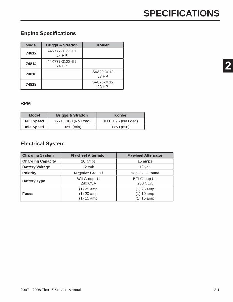
SPECIFICATIONS
2-12007 - 2008 Titan Z Service Manual
2
Model Briggs & Stratton Kohler
74812 44K777-0123-E124 HP
74814 44K777-0123-E124 HP
74816 SV820-001223 HP
74818 SV820-001223 HP
RPM
Model Briggs & Stratton KohlerFull Speed 3650 ± 100 (No Load) 3600 ± 75 (No Load)Idle Speed 1650 (min) 1750 (min)
Electrical System
Charging System Flywheel Alternator Flywheel AlternatorCharging Capacity 16 amps 15 ampsBattery Voltage 12 volt 12 voltPolarity Negative Ground Negative Ground
Battery Type BCI Group U1280 CCA
BCI Group U1260 CCA
Fuses(1) 25 amp(1) 20 amp(1) 15 amp
(1) 25 amp(1) 10 amp(1) 15 amp
SPECIFICATIONS
2-2 2007 - 2008 Titan Z Service Manual
2
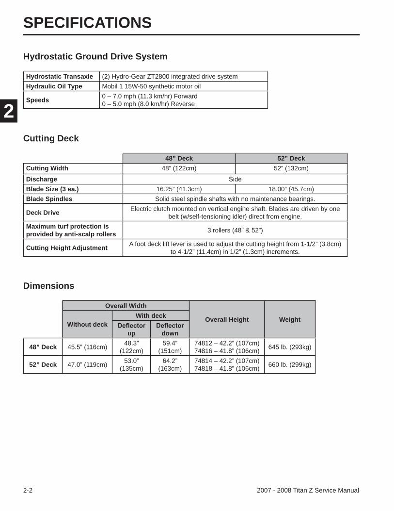
Hydrostatic Ground Drive System
Dimensions
Overall Width
Overall Height WeightWithout deck
With deck
up down
48” Deck 45.5” (116cm) 48.3”(122cm)
59.4”(151cm)
74812 – 42.2” (107cm)74816 – 41.8” (106cm) 645 lb. (293kg)
52” Deck 47.0” (119cm) 53.0”(135cm)
64.2”(163cm)
74814 – 42.2” (107cm)74818 – 41.8” (106cm) 660 lb. (299kg)
Hydrostatic Transaxle (2) Hydro-Gear ZT2800 integrated drive systemHydraulic Oil Type Mobil 1 15W-50 synthetic motor oil
Speeds 0 – 7.0 mph (11.3 km/hr) Forward0 – 5.0 mph (8.0 km/hr) Reverse
Cutting Deck
48” Deck 52” DeckCutting Width 48” (122cm) 52” (132cm)
Discharge SideBlade Size (3 ea.) 16.25” (41.3cm) 18.00” (45.7cm)Blade Spindles Solid steel spindle shafts with no maintenance bearings.
Deck Drive Electric clutch mounted on vertical engine shaft. Blades are driven by one belt (w/self-tensioning idler) direct from engine.
Maximum turf protection is provided by anti-scalp rollers 3 rollers (48” & 52”)
Cutting Height Adjustment A foot deck lift lever is used to adjust the cutting height from 1-1/2” (3.8cm) to 4-1/2” (11.4cm) in 1/2” (1.3cm) increments.
SPECIFICATIONS
2-32007 - 2008 Titan Z Service Manual
2
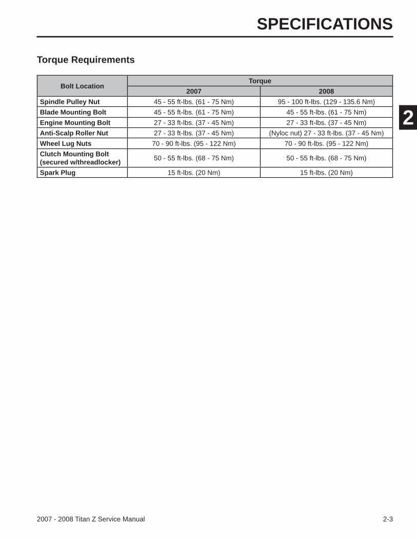
Torque Requirements
Bolt LocationTorque
2007 2008Spindle Pulley Nut 45 - 55 ft-lbs. (61 - 75 Nm) 95 - 100 ft-lbs. (129 - 135.6 Nm)Blade Mounting Bolt 45 - 55 ft-lbs. (61 - 75 Nm) 45 - 55 ft-lbs. (61 - 75 Nm)Engine Mounting Bolt 27 - 33 ft-lbs. (37 - 45 Nm) 27 - 33 ft-lbs. (37 - 45 Nm)Anti-Scalp Roller Nut 27 - 33 ft-lbs. (37 - 45 Nm) (Nyloc nut) 27 - 33 ft-lbs. (37 - 45 Nm)Wheel Lug Nuts 70 - 90 ft-lbs. (95 - 122 Nm) 70 - 90 ft-lbs. (95 - 122 Nm)Clutch Mounting Bolt(secured w/threadlocker) 50 - 55 ft-lbs. (68 - 75 Nm) 50 - 55 ft-lbs. (68 - 75 Nm)
Spark Plug 15 ft-lbs. (20 Nm) 15 ft-lbs. (20 Nm)

SPECIFICATIONS
2-4 2007 - 2008 Titan Z Service Manual
2
THIS PAGE INTENTIONALLY LEFT BLANK.

CHASSIS
3-12007 - 2008 Titan Z Service Manual
3
The unit model and serial number plate is located on the frame behind the seat on the left side (Fig. 001).
A. Read the instructions before servicing or performing maintenance.
B. Time interval.
C. Check oil level.
D. Refer to Operator’s Manual for grease instructions.
E. Check hydraulic oil level and refer to Operator’s manual for further instructions.
F. Check tire pressure.
Fig. 001 IMG-0162
The unit should be greased every 25 hours, or more often when operated in dusty, dirty, or sandy conditions.
Located under the seat is a diagram showing mainten-ance points (Fig. 002).
Fig. 002 grease points line art
Note: Grease Type: NGLI grade #2 multi-purpose gun grease.
pivots.
CHASSIS
3-2 2007 - 2008 Titan Z Service Manual
3
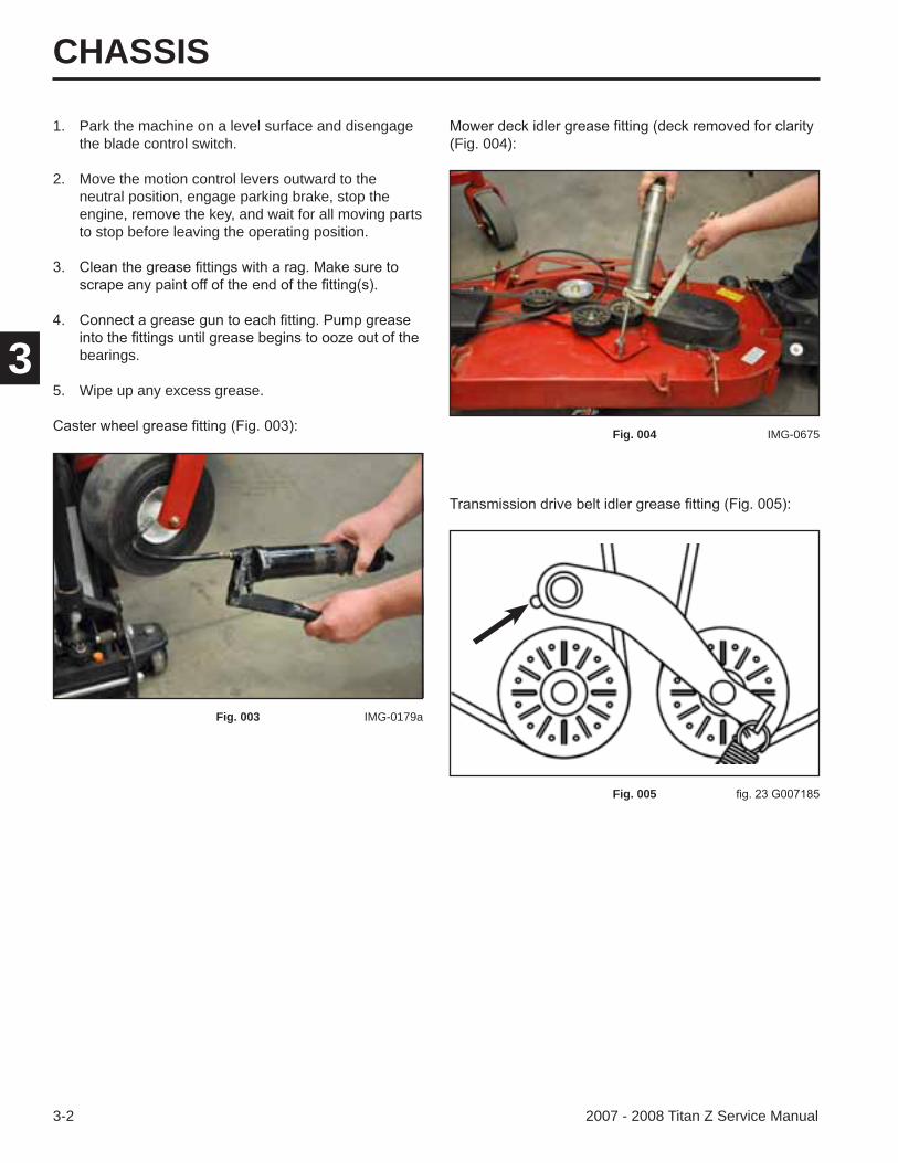
(Fig. 004):1. Park the machine on a level surface and disengage
the blade control switch.
2. Move the motion control levers outward to the neutral position, engage parking brake, stop the engine, remove the key, and wait for all moving parts to stop before leaving the operating position.
bearings.
5. Wipe up any excess grease.
Fig. 003 IMG-0179a
Fig. 004 IMG-0675
Fig. 005
CHASSIS
3-32007 - 2008 Titan Z Service Manual
3
Front Caster Fork Bearing
Front Caster Fork Bearing Removal
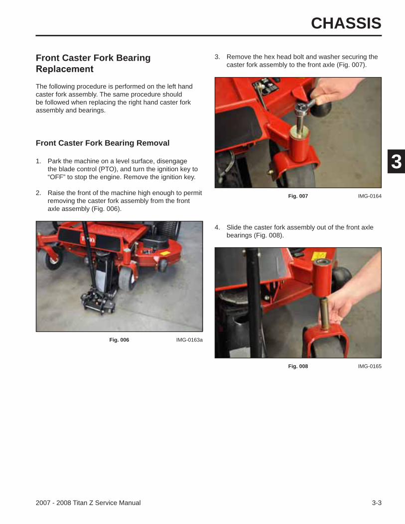
4. Slide the caster fork assembly out of the front axle bearings (Fig. 008).
The following procedure is performed on the left hand caster fork assembly. The same procedure should be followed when replacing the right hand caster fork assembly and bearings.
3. Remove the hex head bolt and washer securing the caster fork assembly to the front axle (Fig. 007).
1. Park the machine on a level surface, disengage the blade control (PTO), and turn the ignition key to “OFF” to stop the engine. Remove the ignition key.
2. Raise the front of the machine high enough to permit removing the caster fork assembly from the front axle assembly (Fig. 006).
Fig. 006 IMG-0163a
Fig. 007 IMG-0164
Fig. 008 IMG-0165
CHASSIS
3-4 2007 - 2008 Titan Z Service Manual
3
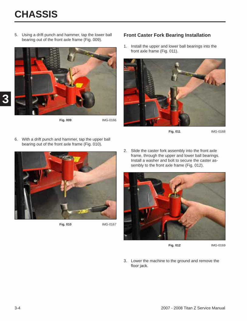
Front Caster Fork Bearing Installation
3. Lower the machine to the ground and remove the
5. Using a drift punch and hammer, tap the lower ball bearing out of the front axle frame (Fig. 009).
6. With a drift punch and hammer, tap the upper ball bearing out of the front axle frame (Fig. 010).
1. Install the upper and lower ball bearings into the front axle frame (Fig. 011).
Fig. 009 IMG-0166
Fig. 010 IMG-0167
Fig. 011 IMG-0168
2. Slide the caster fork assembly into the front axle frame, through the upper and lower ball bearings. Install a washer and bolt to secure the caster as-sembly to the front axle frame (Fig. 012).
Fig. 012 IMG-0169
CHASSIS
3-52007 - 2008 Titan Z Service Manual
3
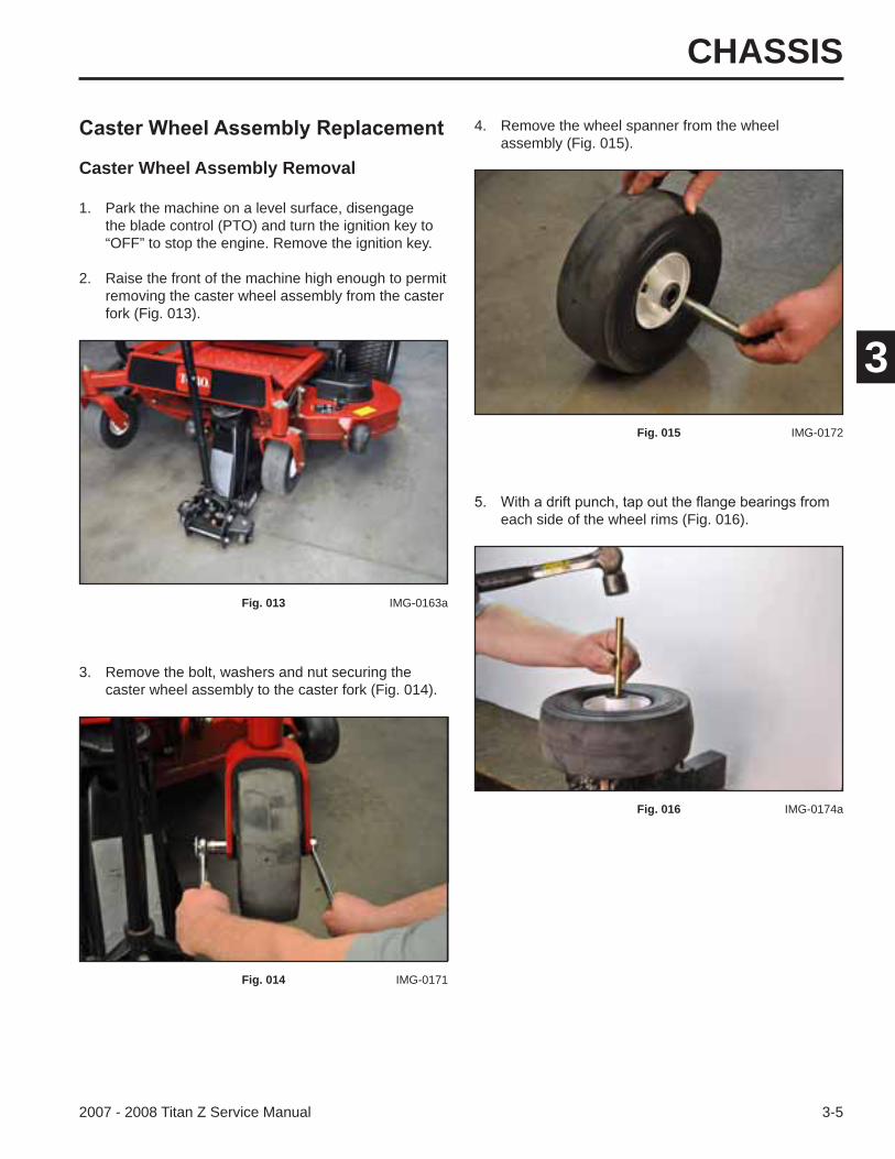
Caster Wheel Assembly Removal
each side of the wheel rims (Fig. 016).
4. Remove the wheel spanner from the wheel assembly (Fig. 015).
1. Park the machine on a level surface, disengage the blade control (PTO) and turn the ignition key to “OFF” to stop the engine. Remove the ignition key.
2. Raise the front of the machine high enough to permit removing the caster wheel assembly from the caster fork (Fig. 013).
Fig. 013 IMG-0163a
3. Remove the bolt, washers and nut securing the caster wheel assembly to the caster fork (Fig. 014).
Fig. 014 IMG-0171
Fig. 015 IMG-0172
Fig. 016 IMG-0174a
CHASSIS
3-6 2007 - 2008 Titan Z Service Manual
3
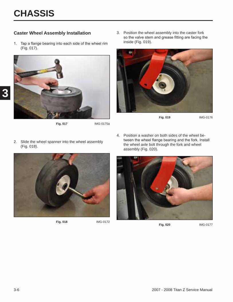
Caster Wheel Assembly Installation
(Fig. 017).
2. Slide the wheel spanner into the wheel assembly (Fig. 018).
3. Position the wheel assembly into the caster fork
inside (Fig. 019).
Fig. 017 IMG-0175a
Fig. 018 IMG-0172
Fig. 019 IMG-0176
4. Position a washer on both sides of the wheel be-
the wheel axle bolt through the fork and wheel assembly (Fig. 020).
Fig. 020 IMG-0177
CHASSIS
3-72007 - 2008 Titan Z Service Manual
3
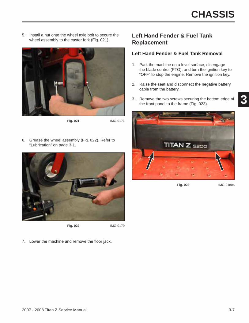
Left Hand Fender & Fuel Tank
Left Hand Fender & Fuel Tank Removal
6. Grease the wheel assembly (Fig. 022). Refer to “Lubrication” on page 3-1.
5. Install a nut onto the wheel axle bolt to secure the wheel assembly to the caster fork (Fig. 021).
1. Park the machine on a level surface, disengage the blade control (PTO), and turn the ignition key to “OFF” to stop the engine. Remove the ignition key.
2. Raise the seat and disconnect the negative battery cable from the battery.
3. Remove the two screws securing the bottom edge of the front panel to the frame (Fig. 023).
Fig. 021 IMG-0171
Fig. 022 IMG-0179
Fig. 023 IMG-0180a
CHASSIS
3-8 2007 - 2008 Titan Z Service Manual
3
4. Lift up on the front panel and pull the panel out of the slots in the seat box to remove the panel (Fig. 024).
5. Remove the two screws securing the left side fender to the front of the seat box (Fig. 025).
A. Bolt and nut B. Screw
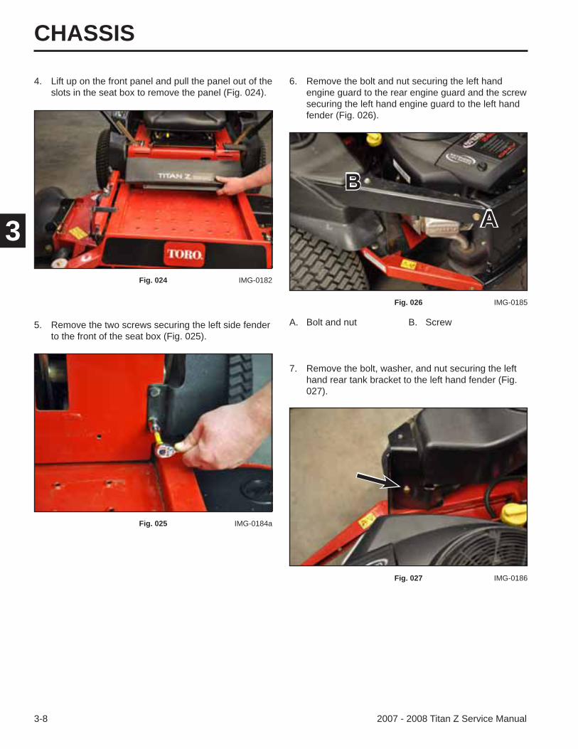
6. Remove the bolt and nut securing the left hand engine guard to the rear engine guard and the screw securing the left hand engine guard to the left hand fender (Fig. 026).
Fig. 024 IMG-0182
Fig. 025 IMG-0184a
Fig. 026 IMG-0185
7. Remove the bolt, washer, and nut securing the left hand rear tank bracket to the left hand fender (Fig. 027).
Fig. 027 IMG-0186
AB
CHASSIS
3-92007 - 2008 Titan Z Service Manual
3
9. Lift the left hand fender off of the gas tank (Fig. 029).
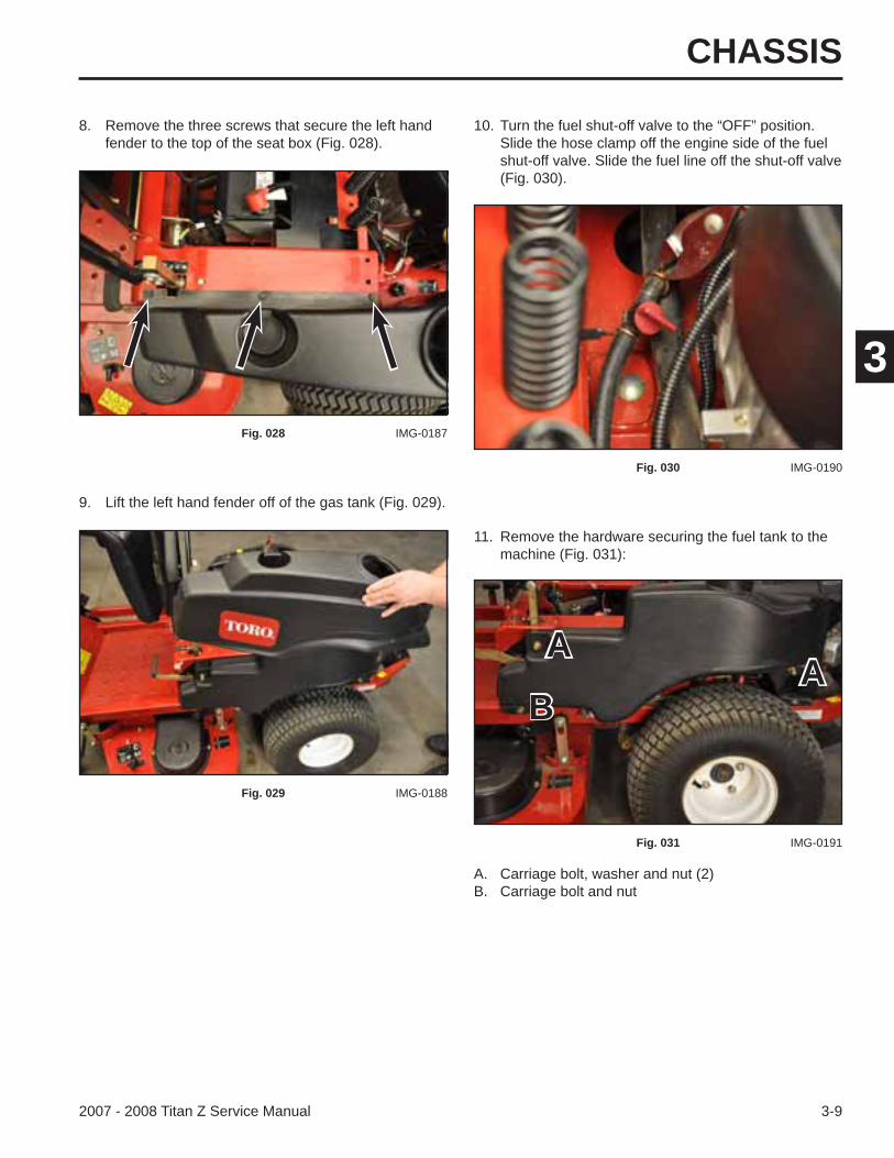
11. Remove the hardware securing the fuel tank to the machine (Fig. 031):
8. Remove the three screws that secure the left hand fender to the top of the seat box (Fig. 028).
10. Turn the fuel shut-off valve to the “OFF” position. Slide the hose clamp off the engine side of the fuel shut-off valve. Slide the fuel line off the shut-off valve (Fig. 030).
Fig. 028 IMG-0187
Fig. 029 IMG-0188
Fig. 030 IMG-0190
Fig. 031 IMG-0191
A. Carriage bolt, washer and nut (2)B. Carriage bolt and nut
AA
B
CHASSIS
3-10 2007 - 2008 Titan Z Service Manual
3
Left Hand Fender & Fuel Tank Installation12. The fuel line coming from the fuel tank is held in place by a clamp located on the side of the seat box assembly. Open the clamp to release the fuel line (Fig. 032).
13. Remove the fuel tank from the machine (Fig. 033).
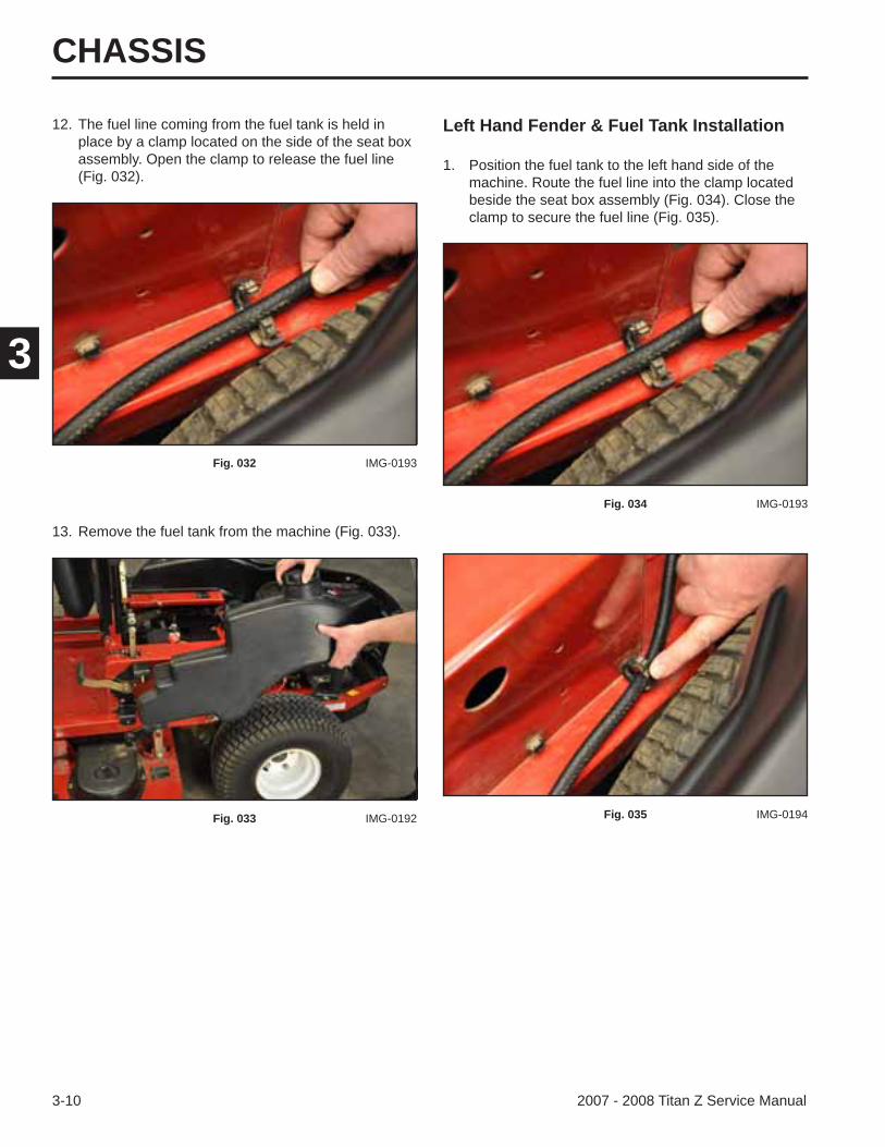
1. Position the fuel tank to the left hand side of the machine. Route the fuel line into the clamp located beside the seat box assembly (Fig. 034). Close the clamp to secure the fuel line (Fig. 035).
Fig. 032 IMG-0193
Fig. 033 IMG-0192
Fig. 034 IMG-0193
Fig. 035 IMG-0194
CHASSIS
3-112007 - 2008 Titan Z Service Manual
3
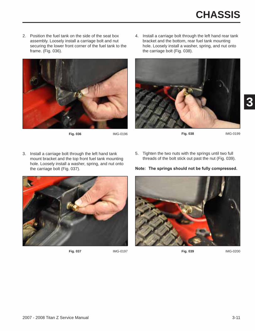
2. Position the fuel tank on the side of the seat box assembly. Loosely install a carriage bolt and nut securing the lower front corner of the fuel tank to the frame. (Fig. 036).
4. Install a carriage bolt through the left hand rear tank bracket and the bottom, rear fuel tank mounting hole. Loosely install a washer, spring, and nut onto the carriage bolt (Fig. 038).
Fig. 036 IMG-0196
3. Install a carriage bolt through the left hand tank mount bracket and the top front fuel tank mounting hole. Loosely install a washer, spring, and nut onto the carriage bolt (Fig. 037).
Fig. 037 IMG-0197
Fig. 038 IMG-0199
5. Tighten the two nuts with the springs until two full threads of the bolt stick out past the nut (Fig. 039).
Fig. 039 IMG-0200
CHASSIS
3-12 2007 - 2008 Titan Z Service Manual
3
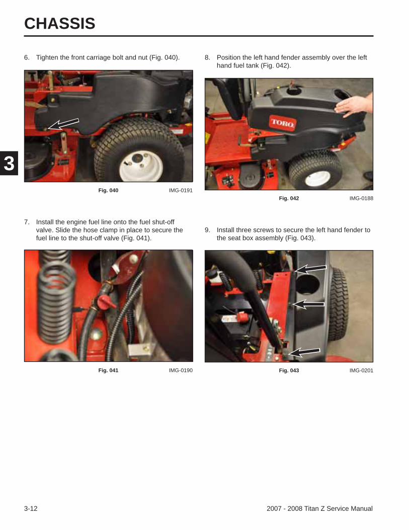
6. Tighten the front carriage bolt and nut (Fig. 040).
7. Install the engine fuel line onto the fuel shut-off valve. Slide the hose clamp in place to secure the fuel line to the shut-off valve (Fig. 041).
9. Install three screws to secure the left hand fender to the seat box assembly (Fig. 043).
8. Position the left hand fender assembly over the left hand fuel tank (Fig. 042).
Fig. 040 IMG-0191
Fig. 041 IMG-0190
Fig. 042 IMG-0188
Fig. 043 IMG-0201
CHASSIS
3-132007 - 2008 Titan Z Service Manual
3
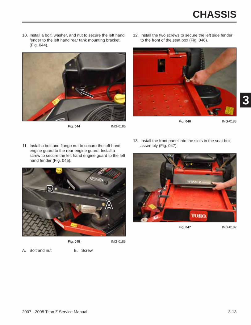
13. Install the front panel into the slots in the seat box assembly (Fig. 047).
10. Install a bolt, washer, and nut to secure the left hand fender to the left hand rear tank mounting bracket (Fig. 044).
12. Install the two screws to secure the left side fender to the front of the seat box (Fig. 046).
A. Bolt and nut B. Screw
Fig. 044 IMG-0186Fig. 046 IMG-0183
Fig. 047 IMG-0182
engine guard to the rear engine guard. Install a screw to secure the left hand engine guard to the left hand fender (Fig. 045).
Fig. 045 IMG-0185
AB
CHASSIS
3-14 2007 - 2008 Titan Z Service Manual
3
Right Hand Fender Removal
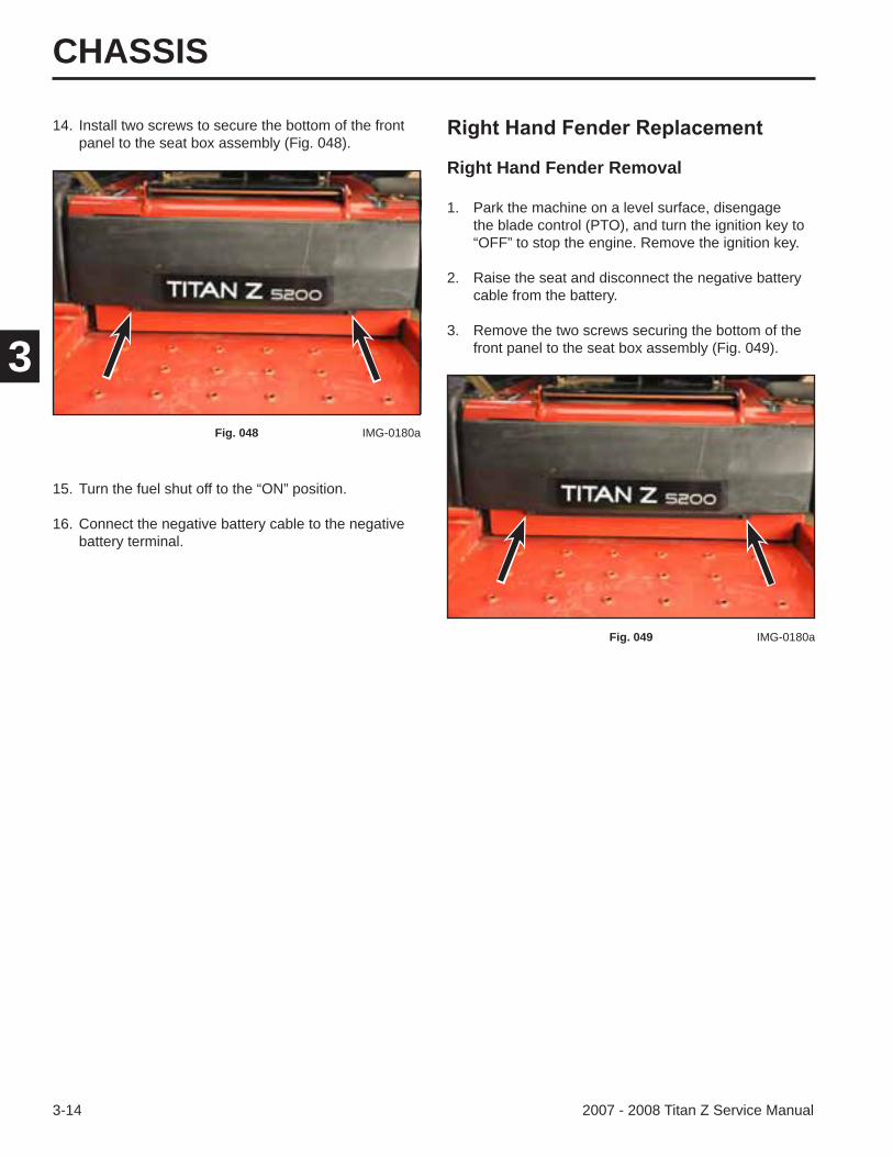
14. Install two screws to secure the bottom of the front panel to the seat box assembly (Fig. 048).
15. Turn the fuel shut off to the “ON” position.
16. Connect the negative battery cable to the negative battery terminal.
1. Park the machine on a level surface, disengage the blade control (PTO), and turn the ignition key to “OFF” to stop the engine. Remove the ignition key.
2. Raise the seat and disconnect the negative battery cable from the battery.
3. Remove the two screws securing the bottom of the front panel to the seat box assembly (Fig. 049).
Fig. 048 IMG-0180a
Fig. 049 IMG-0180a
CHASSIS
3-152007 - 2008 Titan Z Service Manual
3
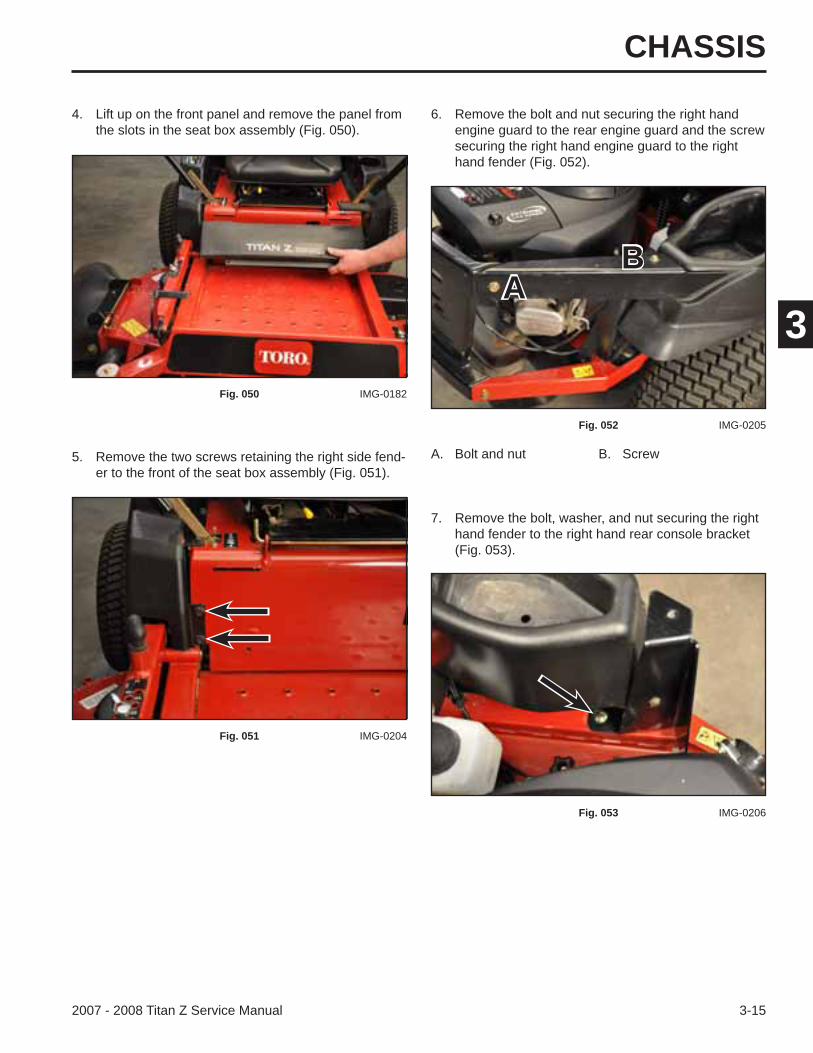
5. Remove the two screws retaining the right side fend-er to the front of the seat box assembly (Fig. 051).
A. Bolt and nut B. Screw
4. Lift up on the front panel and remove the panel from the slots in the seat box assembly (Fig. 050).
6. Remove the bolt and nut securing the right hand engine guard to the rear engine guard and the screw securing the right hand engine guard to the right hand fender (Fig. 052).
Fig. 050 IMG-0182
Fig. 051 IMG-0204
Fig. 052 IMG-0205
7. Remove the bolt, washer, and nut securing the right hand fender to the right hand rear console bracket (Fig. 053).
Fig. 053 IMG-0206
AB
CHASSIS
3-16 2007 - 2008 Titan Z Service Manual
3
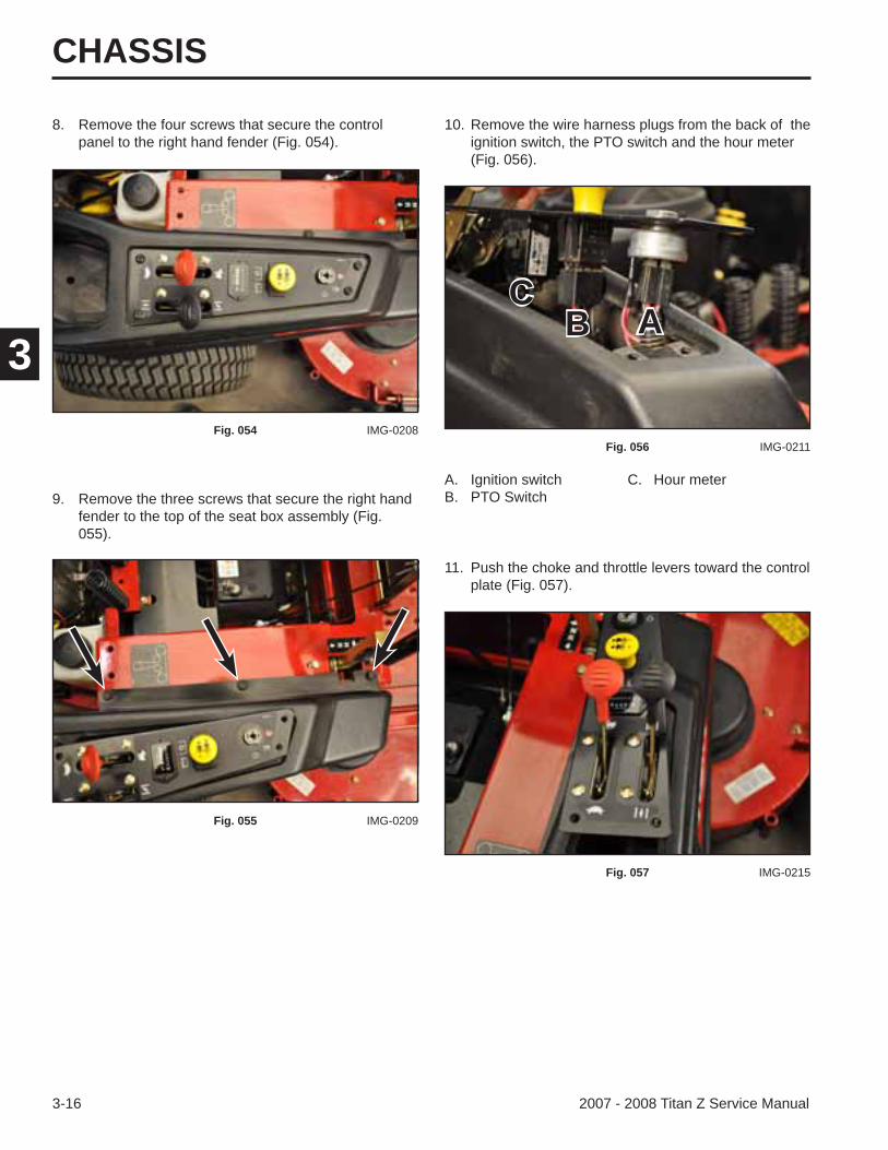
8. Remove the four screws that secure the control panel to the right hand fender (Fig. 054).
9. Remove the three screws that secure the right hand fender to the top of the seat box assembly (Fig. 055).
A. Ignition switch C. Hour meterB. PTO Switch
10. Remove the wire harness plugs from the back of the ignition switch, the PTO switch and the hour meter (Fig. 056).
Fig. 054 IMG-0208
Fig. 055 IMG-0209
Fig. 056 IMG-0211
11. Push the choke and throttle levers toward the control plate (Fig. 057).
Fig. 057 IMG-0215
ABC
CHASSIS
3-172007 - 2008 Titan Z Service Manual
3
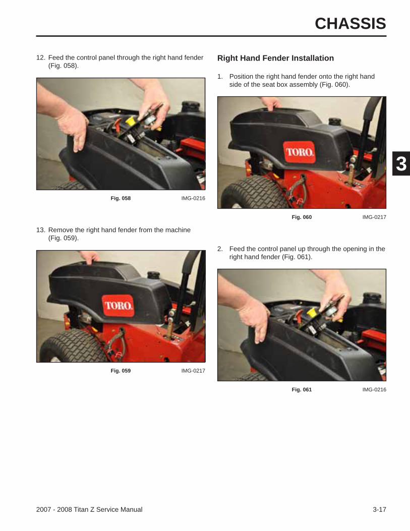
Right Hand Fender Installation
13. Remove the right hand fender from the machine (Fig. 059).
2. Feed the control panel up through the opening in the right hand fender (Fig. 061).
12. Feed the control panel through the right hand fender (Fig. 058).
1. Position the right hand fender onto the right hand side of the seat box assembly (Fig. 060).
Fig. 058 IMG-0216
Fig. 059 IMG-0217
Fig. 060 IMG-0217
Fig. 061 IMG-0216
CHASSIS
3-18 2007 - 2008 Titan Z Service Manual
3
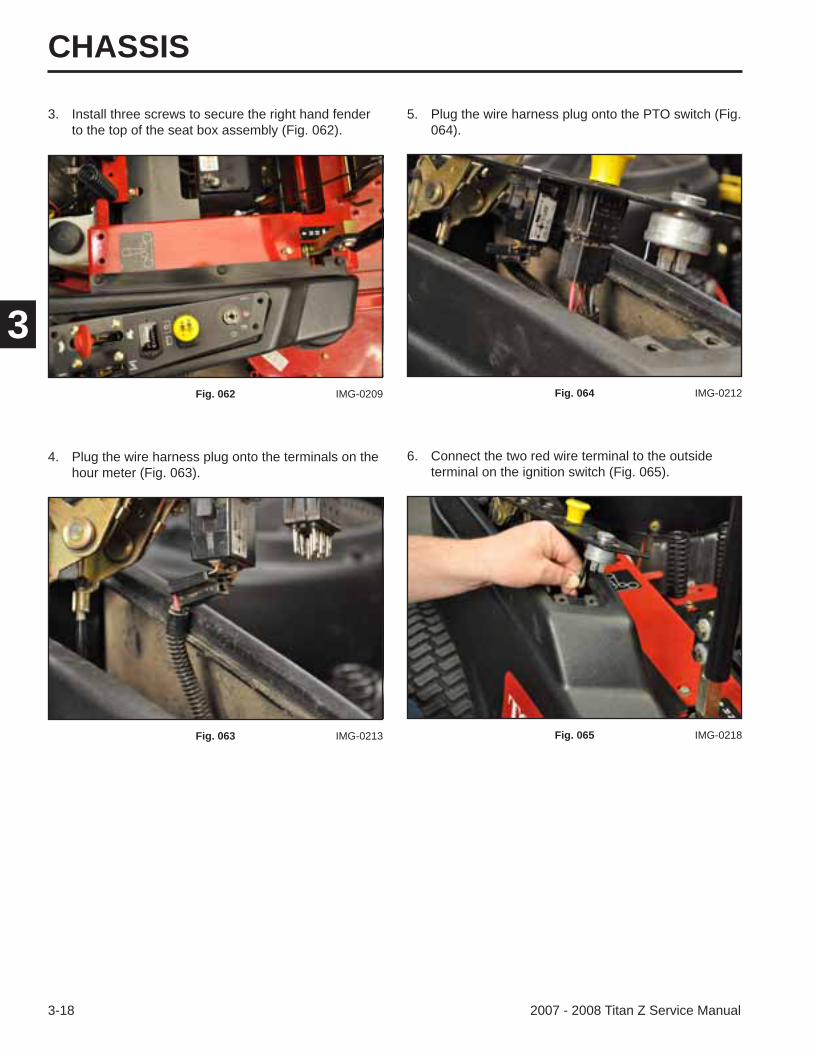
3. Install three screws to secure the right hand fender to the top of the seat box assembly (Fig. 062).
4. Plug the wire harness plug onto the terminals on the hour meter (Fig. 063).
6. Connect the two red wire terminal to the outside terminal on the ignition switch (Fig. 065).
5. Plug the wire harness plug onto the PTO switch (Fig. 064).
Fig. 062 IMG-0209
Fig. 063 IMG-0213
Fig. 064 IMG-0212
Fig. 065 IMG-0218
CHASSIS
3-192007 - 2008 Titan Z Service Manual
3
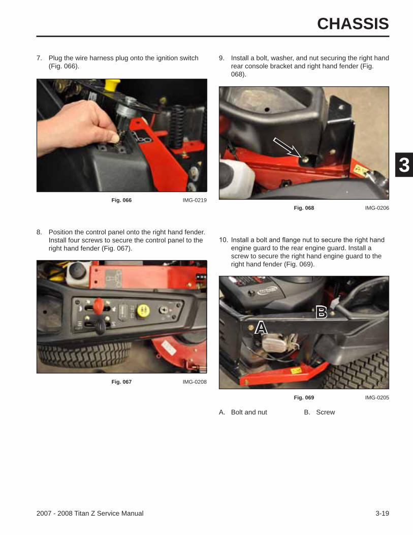
8. Position the control panel onto the right hand fender. Install four screws to secure the control panel to the right hand fender (Fig. 067).
7. Plug the wire harness plug onto the ignition switch (Fig. 066).
9. Install a bolt, washer, and nut securing the right hand rear console bracket and right hand fender (Fig. 068).
Fig. 066 IMG-0219
Fig. 067 IMG-0208
Fig. 068 IMG-0206
engine guard to the rear engine guard. Install a screw to secure the right hand engine guard to the right hand fender (Fig. 069).
Fig. 069 IMG-0205
A. Bolt and nut B. Screw
AB

CHASSIS
3-20 2007 - 2008 Titan Z Service Manual
3
11. Install two screws to secure the right hand fender to the front of the seat box assembly (Fig. 070).
12. Install the front panel into the slots in the seat box assembly (Fig. 071).
14. Connect the negative battery cable to the negative battery terminal.
13. Install two screws to secure the bottom of the front panel to the seat box assembly (Fig. 072).
Fig. 070 IMG-0204
Fig. 071 IMG-0182
Fig. 072 IMG-0180a
CHASSIS
3-212007 - 2008 Titan Z Service Manual
3
Seat Box Removal
5. Remove the wire harness from the wire clamp located on the seat plate (Fig. 075).
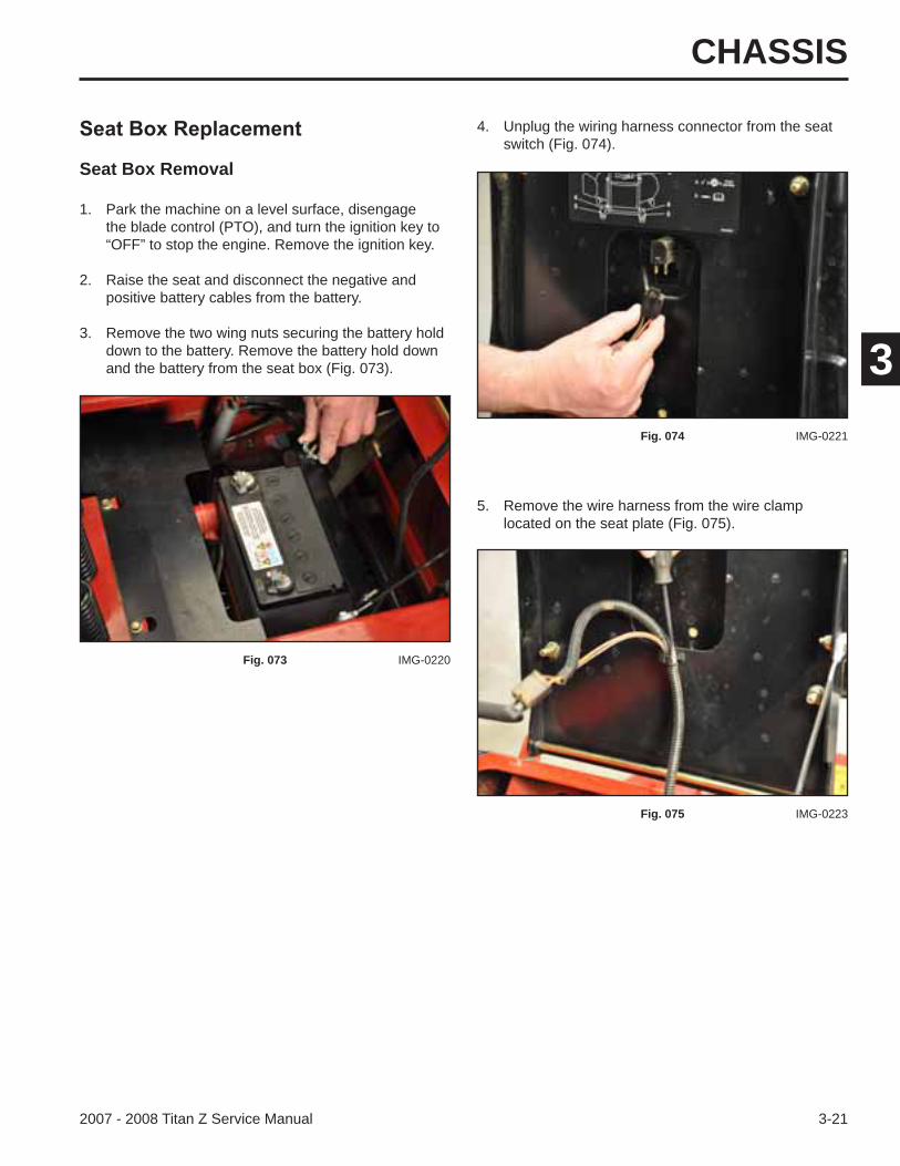
1. Park the machine on a level surface, disengage the blade control (PTO), and turn the ignition key to “OFF” to stop the engine. Remove the ignition key.
2. Raise the seat and disconnect the negative and positive battery cables from the battery.
3. Remove the two wing nuts securing the battery hold down to the battery. Remove the battery hold down and the battery from the seat box (Fig. 073).
4. Unplug the wiring harness connector from the seat switch (Fig. 074).
Fig. 073 IMG-0220
Fig. 074 IMG-0221
Fig. 075 IMG-0223
CHASSIS
3-22 2007 - 2008 Titan Z Service Manual
3
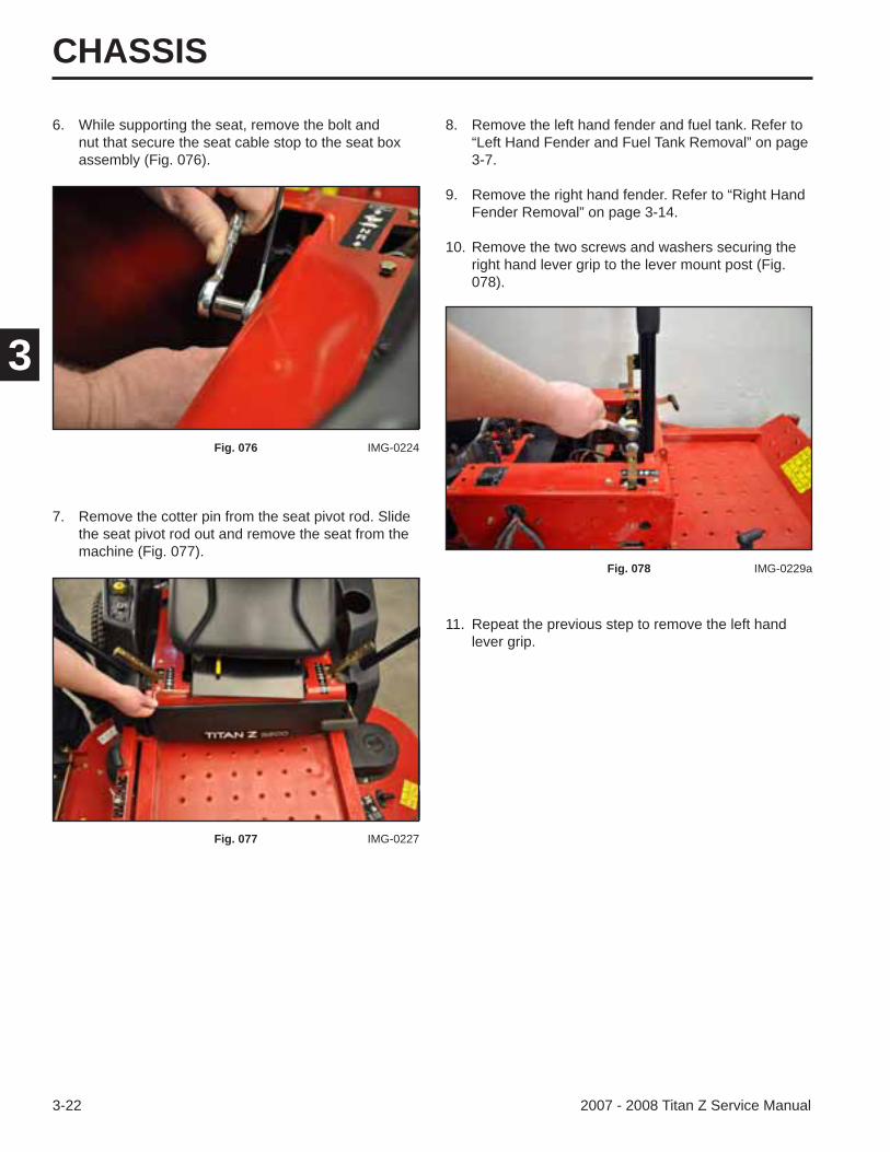
6. While supporting the seat, remove the bolt and nut that secure the seat cable stop to the seat box assembly (Fig. 076).
7. Remove the cotter pin from the seat pivot rod. Slide the seat pivot rod out and remove the seat from the machine (Fig. 077).
11. Repeat the previous step to remove the left hand lever grip.
8. Remove the left hand fender and fuel tank. Refer to “Left Hand Fender and Fuel Tank Removal” on page 3-7.
9. Remove the right hand fender. Refer to “Right Hand Fender Removal” on page 3-14.
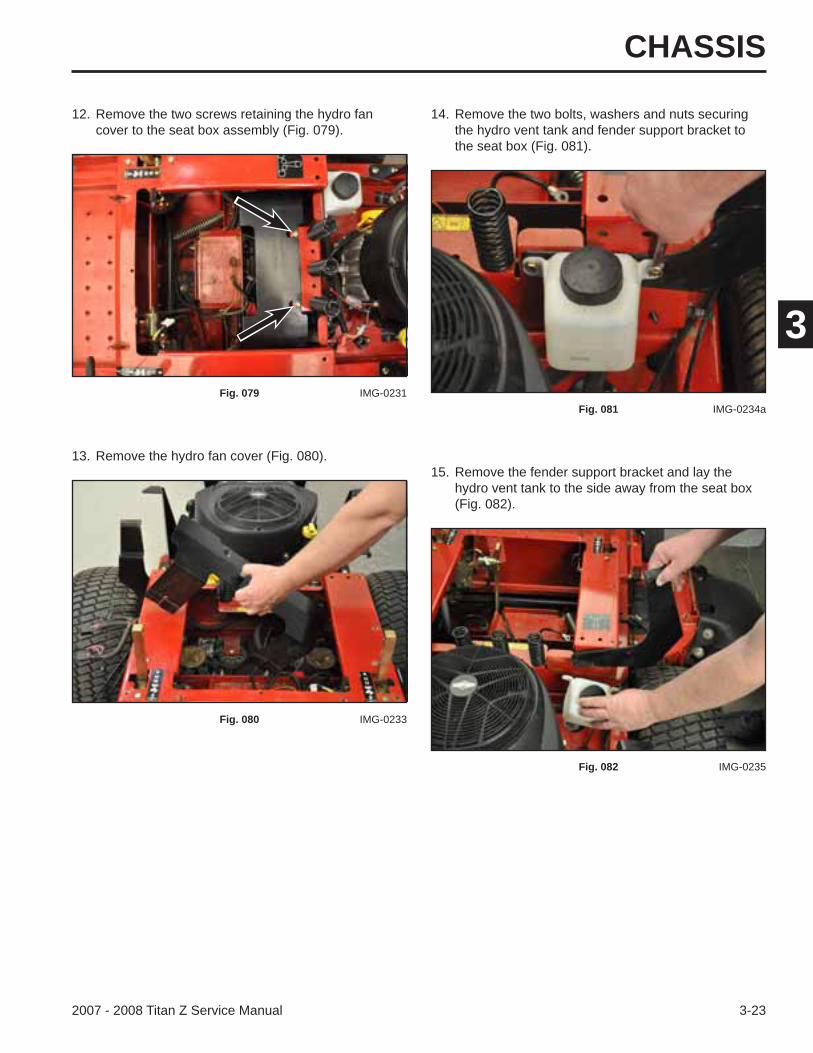
10. Remove the two screws and washers securing the right hand lever grip to the lever mount post (Fig. 078).
Fig. 076 IMG-0224
Fig. 077 IMG-0227
Fig. 078 IMG-0229a
CHASSIS
3-232007 - 2008 Titan Z Service Manual
3
13. Remove the hydro fan cover (Fig. 080).15. Remove the fender support bracket and lay the
hydro vent tank to the side away from the seat box (Fig. 082).
12. Remove the two screws retaining the hydro fan cover to the seat box assembly (Fig. 079).
14. Remove the two bolts, washers and nuts securing the hydro vent tank and fender support bracket to the seat box (Fig. 081).
Fig. 079 IMG-0231
Fig. 080 IMG-0233
Fig. 081 IMG-0234a
Fig. 082 IMG-0235
CHASSIS
3-24 2007 - 2008 Titan Z Service Manual
3
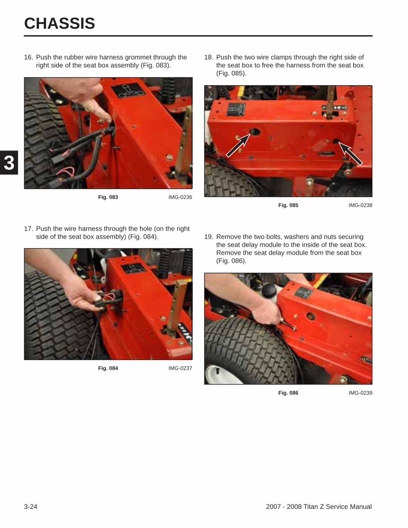
16. Push the rubber wire harness grommet through the right side of the seat box assembly (Fig. 083).
17. Push the wire harness through the hole (on the right side of the seat box assembly) (Fig. 084).
18. Push the two wire clamps through the right side of the seat box to free the harness from the seat box (Fig. 085).
Fig. 083 IMG-0236
Fig. 084 IMG-0237
Fig. 085 IMG-0238
19. Remove the two bolts, washers and nuts securing the seat delay module to the inside of the seat box.Remove the seat delay module from the seat box (Fig. 086).
Fig. 086 IMG-0239
CHASSIS
3-252007 - 2008 Titan Z Service Manual
3
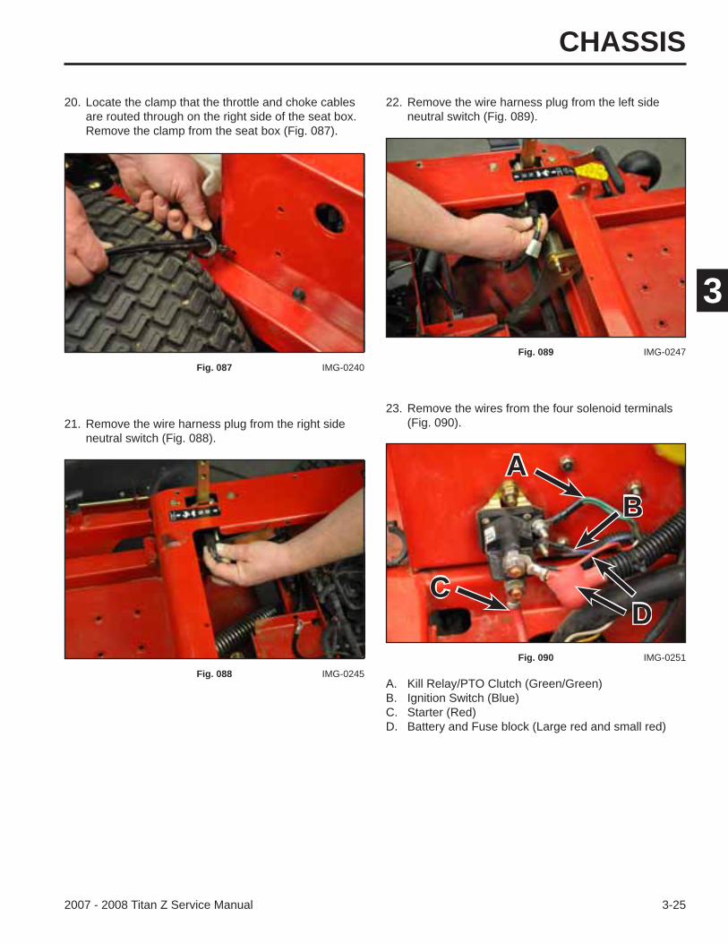
21. Remove the wire harness plug from the right side neutral switch (Fig. 088).
23. Remove the wires from the four solenoid terminals (Fig. 090).
20. Locate the clamp that the throttle and choke cables are routed through on the right side of the seat box. Remove the clamp from the seat box (Fig. 087).
22. Remove the wire harness plug from the left side neutral switch (Fig. 089).
Fig. 087 IMG-0240
Fig. 088 IMG-0245
Fig. 089 IMG-0247
Fig. 090 IMG-0251
A. Kill Relay/PTO Clutch (Green/Green)B. Ignition Switch (Blue)C. Starter (Red)D. Battery and Fuse block (Large red and small red)
A
C
B
D
CHASSIS
3-26 2007 - 2008 Titan Z Service Manual
3
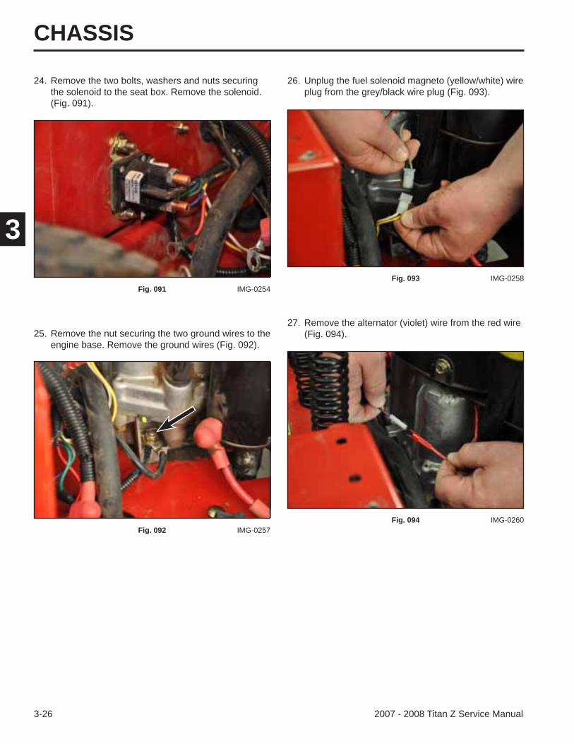
24. Remove the two bolts, washers and nuts securing the solenoid to the seat box. Remove the solenoid. (Fig. 091).
25. Remove the nut securing the two ground wires to the engine base. Remove the ground wires (Fig. 092).
27. Remove the alternator (violet) wire from the red wire (Fig. 094).
26. Unplug the fuel solenoid magneto (yellow/white) wire plug from the grey/black wire plug (Fig. 093).
Fig. 091 IMG-0254
Fig. 092 IMG-0257
Fig. 093 IMG-0258
Fig. 094 IMG-0260
CHASSIS
3-272007 - 2008 Titan Z Service Manual
3
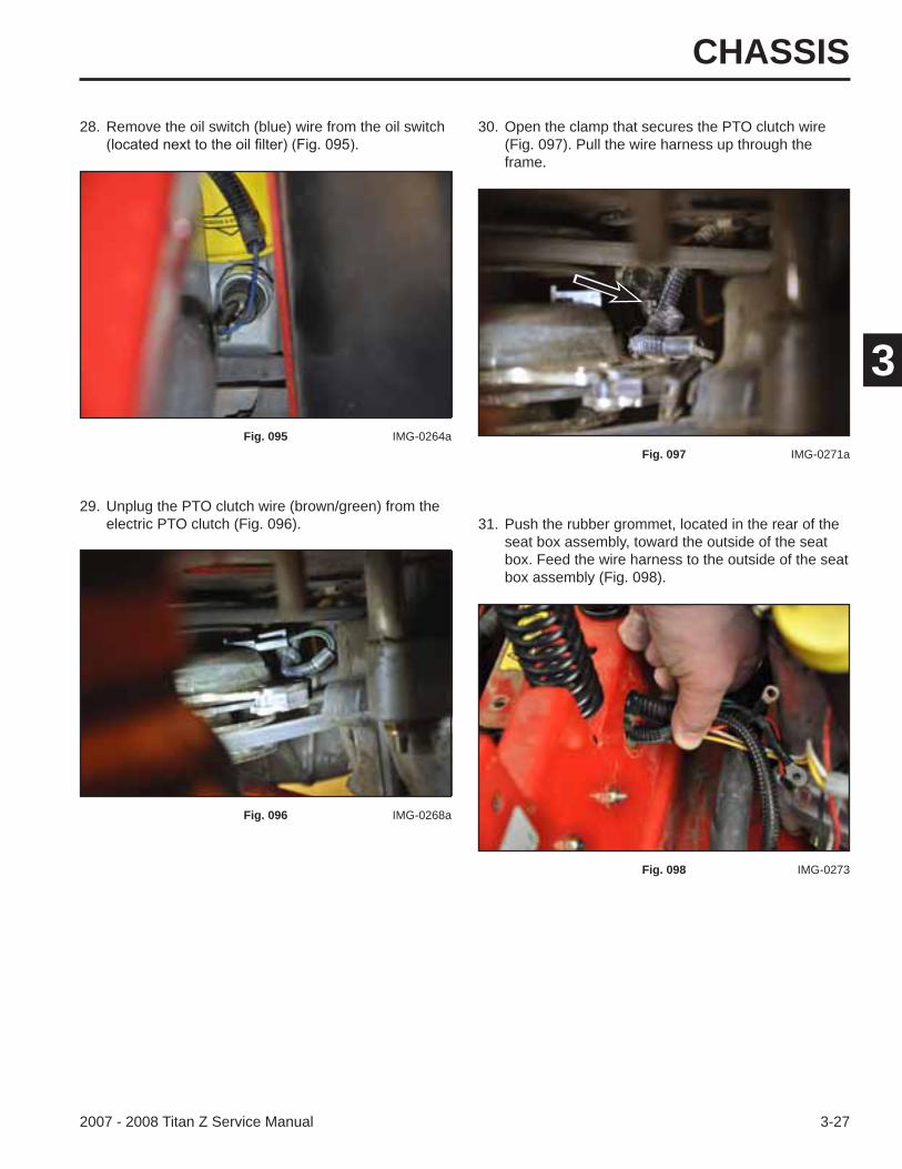
29. Unplug the PTO clutch wire (brown/green) from the electric PTO clutch (Fig. 096).
28. Remove the oil switch (blue) wire from the oil switch 30. Open the clamp that secures the PTO clutch wire (Fig. 097). Pull the wire harness up through the frame.
Fig. 095 IMG-0264a
Fig. 096 IMG-0268a
Fig. 097 IMG-0271a
31. Push the rubber grommet, located in the rear of the seat box assembly, toward the outside of the seat box. Feed the wire harness to the outside of the seat box assembly (Fig. 098).
Fig. 098 IMG-0273
CHASSIS
3-28 2007 - 2008 Titan Z Service Manual
3
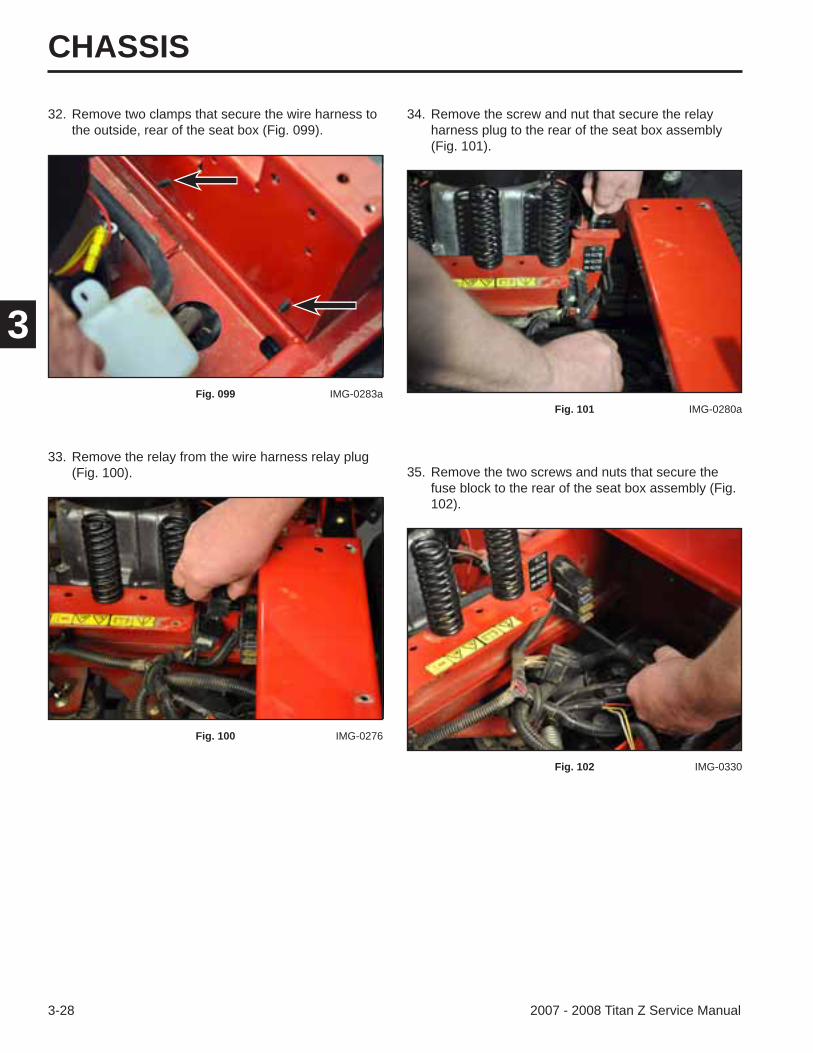
32. Remove two clamps that secure the wire harness to the outside, rear of the seat box (Fig. 099).
33. Remove the relay from the wire harness relay plug (Fig. 100). 35. Remove the two screws and nuts that secure the
fuse block to the rear of the seat box assembly (Fig. 102).
34. Remove the screw and nut that secure the relay harness plug to the rear of the seat box assembly (Fig. 101).
Fig. 099 IMG-0283a
Fig. 100 IMG-0276
Fig. 101 IMG-0280a
Fig. 102 IMG-0330

CHASSIS
3-292007 - 2008 Titan Z Service Manual
3
37. Remove the clamp retaining the wire harness to the left side of the seat box assembly (Fig. 104).
39. Remove the brake assembly carriage bolt (Fig. 106).
36. Remove the clamp for the fuel hose, located on the left rear side of the seat box assembly (Fig. 103).
38. Remove the nut from the brake assembly carriage bolt (Fig. 105).
Fig. 103 IMG-0284
Fig. 104 IMG-0285
Fig. 105 IMG-0287a
Fig. 106 IMG-0288
CHASSIS
3-30 2007 - 2008 Titan Z Service Manual
3
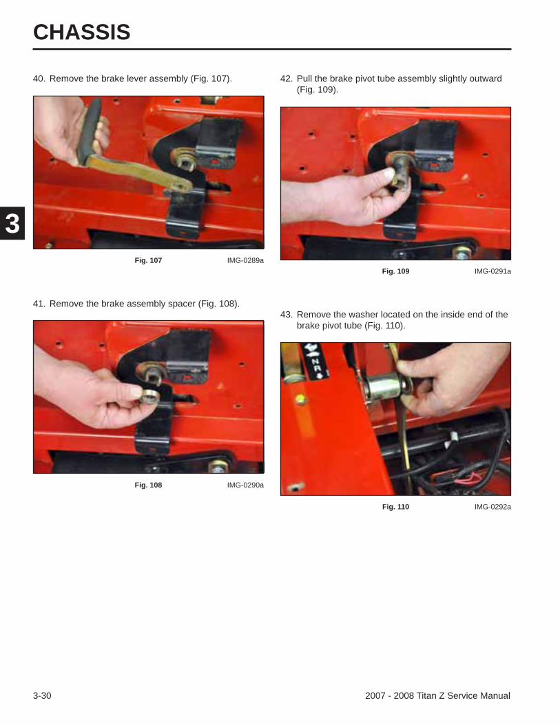
40. Remove the brake lever assembly (Fig. 107).
41. Remove the brake assembly spacer (Fig. 108).43. Remove the washer located on the inside end of the
brake pivot tube (Fig. 110).
42. Pull the brake pivot tube assembly slightly outward (Fig. 109).
Fig. 107 IMG-0289a
Fig. 108 IMG-0290a
Fig. 109 IMG-0291a
Fig. 110 IMG-0292a
CHASSIS
3-312007 - 2008 Titan Z Service Manual
3
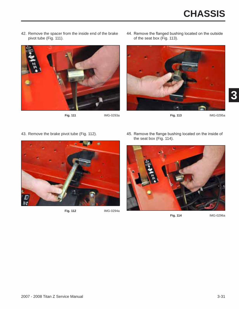
43. Remove the brake pivot tube (Fig. 112).the seat box (Fig. 114).
42. Remove the spacer from the inside end of the brake pivot tube (Fig. 111). of the seat box (Fig. 113).
Fig. 111 IMG-0293a
Fig. 112 IMG-0294a
Fig. 113 IMG-0295a
Fig. 114 IMG-0296a
CHASSIS
3-32 2007 - 2008 Titan Z Service Manual
3
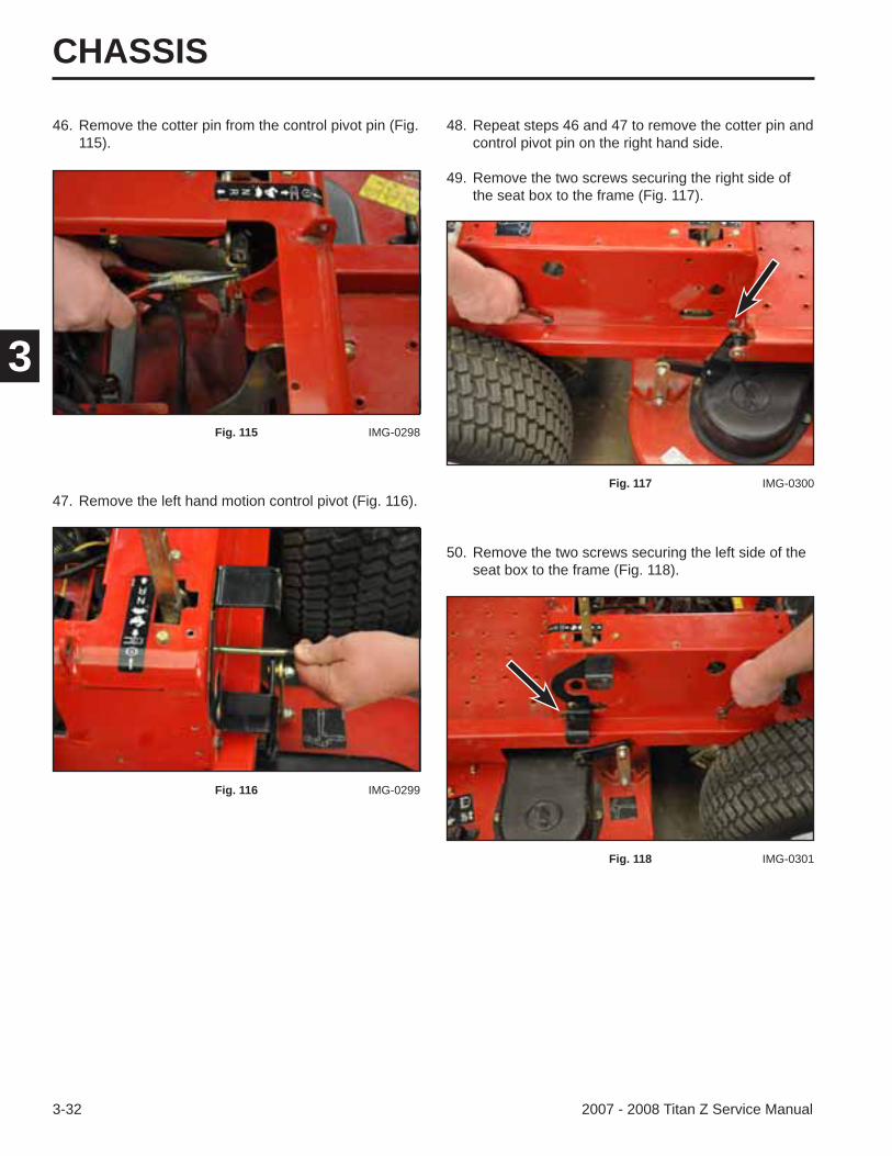
46. Remove the cotter pin from the control pivot pin (Fig. 115).
50. Remove the two screws securing the left side of the seat box to the frame (Fig. 118).
48. Repeat steps 46 and 47 to remove the cotter pin and control pivot pin on the right hand side.
49. Remove the two screws securing the right side of the seat box to the frame (Fig. 117).
Fig. 115 IMG-0298
47. Remove the left hand motion control pivot (Fig. 116).
Fig. 116 IMG-0299
Fig. 117 IMG-0300
Fig. 118 IMG-0301
CHASSIS
3-332007 - 2008 Titan Z Service Manual
3
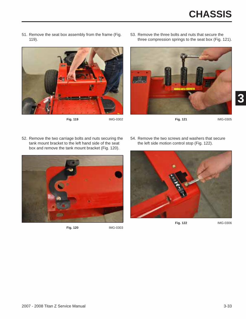
52. Remove the two carriage bolts and nuts securing the tank mount bracket to the left hand side of the seat box and remove the tank mount bracket (Fig. 120).
54. Remove the two screws and washers that secure the left side motion control stop (Fig. 122).
51. Remove the seat box assembly from the frame (Fig. 119).
53. Remove the three bolts and nuts that secure the three compression springs to the seat box (Fig. 121).
Fig. 119 IMG-0302
Fig. 120 IMG-0303
Fig. 121 IMG-0305
Fig. 122 IMG-0306
CHASSIS
3-34 2007 - 2008 Titan Z Service Manual
3
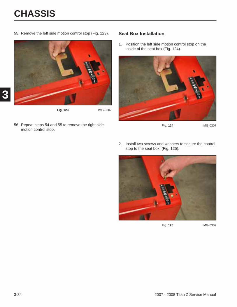
Seat Box Installation55. Remove the left side motion control stop (Fig. 123).
56. Repeat steps 54 and 55 to remove the right side motion control stop.
2. Install two screws and washers to secure the control stop to the seat box. (Fig. 125).
1. Position the left side motion control stop on the inside of the seat box (Fig. 124).
Fig. 123 IMG-0307
Fig. 124 IMG-0307
Fig. 125 IMG-0309
CHASSIS
3-352007 - 2008 Titan Z Service Manual
3
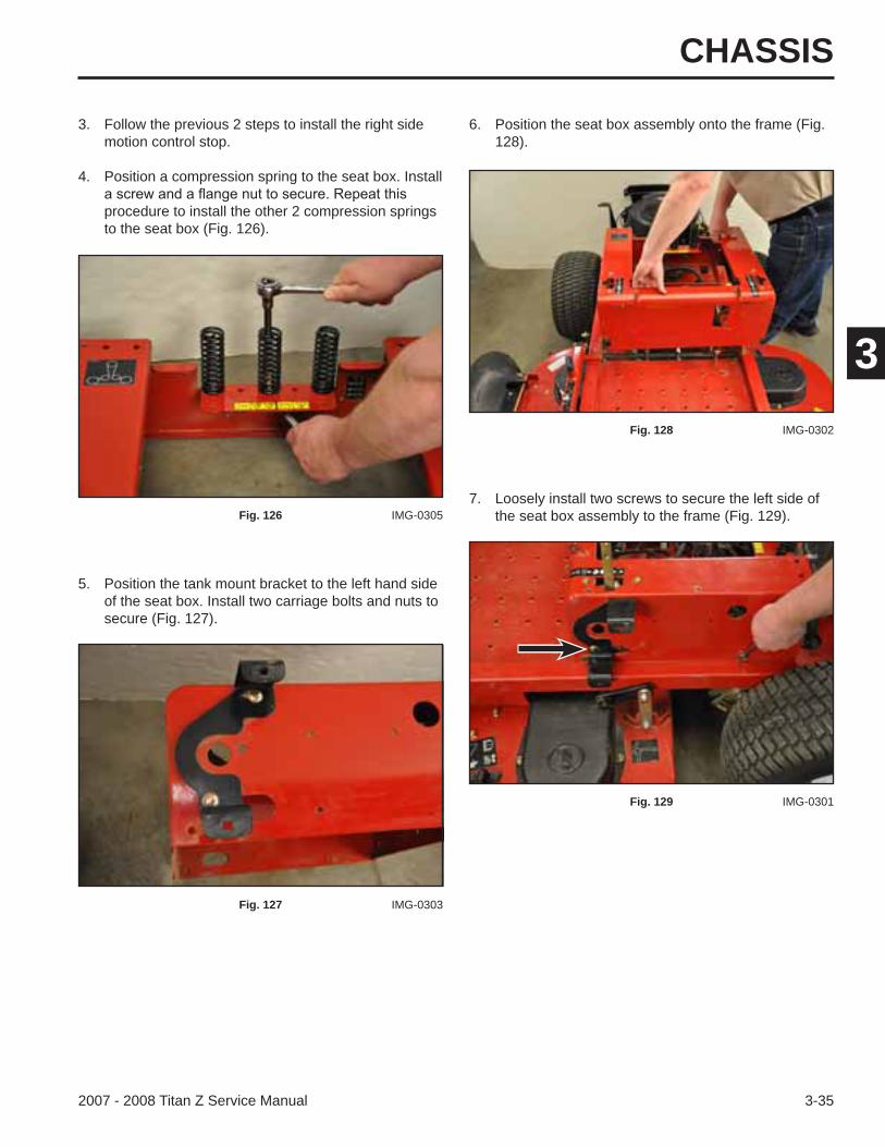
5. Position the tank mount bracket to the left hand side of the seat box. Install two carriage bolts and nuts to secure (Fig. 127).
7. Loosely install two screws to secure the left side of the seat box assembly to the frame (Fig. 129).
3. Follow the previous 2 steps to install the right side motion control stop.
4. Position a compression spring to the seat box. Install
procedure to install the other 2 compression springs to the seat box (Fig. 126).
6. Position the seat box assembly onto the frame (Fig. 128).
Fig. 126 IMG-0305
Fig. 127 IMG-0303
Fig. 128 IMG-0302
Fig. 129 IMG-0301
CHASSIS
3-36 2007 - 2008 Titan Z Service Manual
3
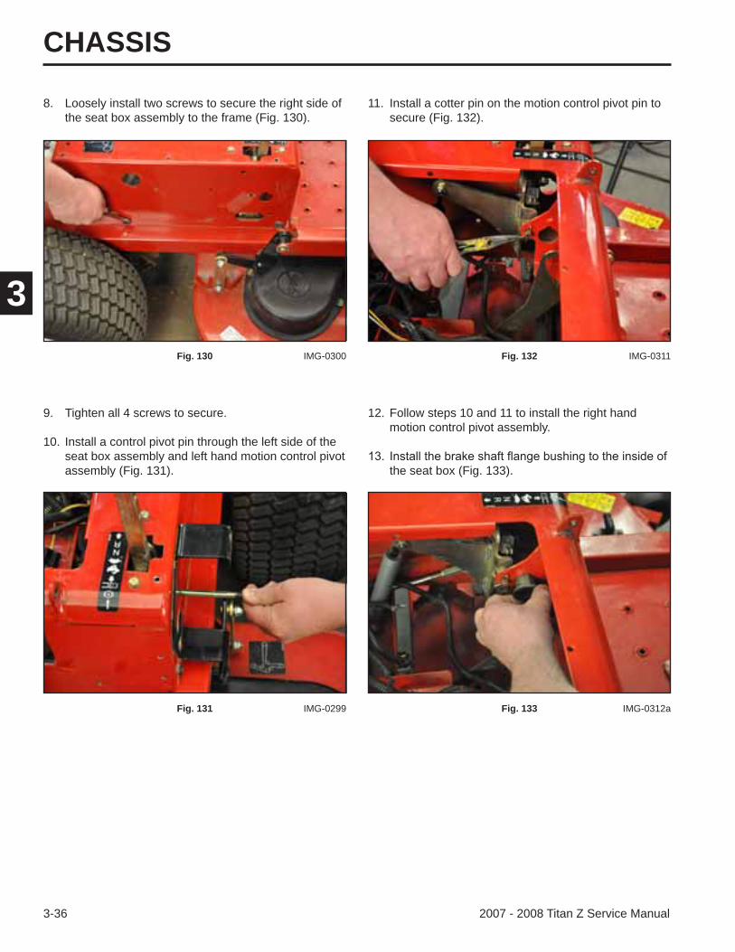
8. Loosely install two screws to secure the right side of the seat box assembly to the frame (Fig. 130).
11. Install a cotter pin on the motion control pivot pin to secure (Fig. 132).
Fig. 130 IMG-0300
9. Tighten all 4 screws to secure.
10. Install a control pivot pin through the left side of the seat box assembly and left hand motion control pivot assembly (Fig. 131).
Fig. 131 IMG-0299
Fig. 132 IMG-0311
12. Follow steps 10 and 11 to install the right hand motion control pivot assembly.
the seat box (Fig. 133).
Fig. 133 IMG-0312a
CHASSIS
3-372007 - 2008 Titan Z Service Manual
3
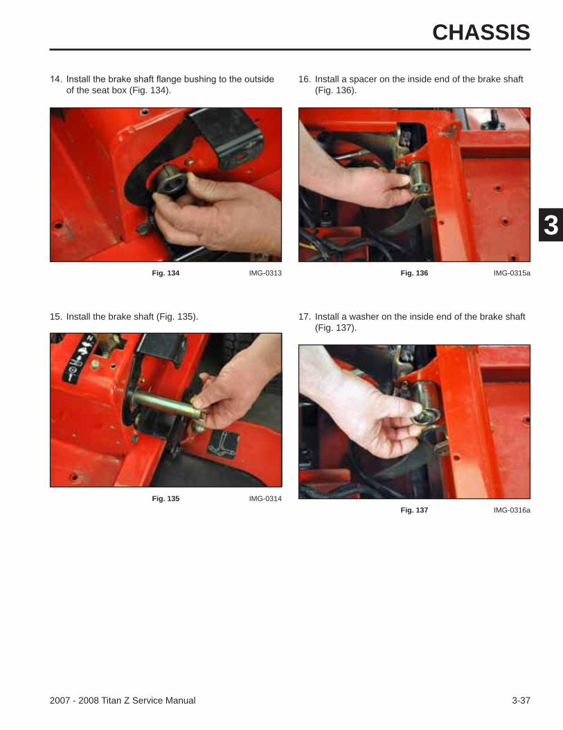
15. Install the brake shaft (Fig. 135). 17. Install a washer on the inside end of the brake shaft (Fig. 137).
of the seat box (Fig. 134).16. Install a spacer on the inside end of the brake shaft
(Fig. 136).
Fig. 134 IMG-0313
Fig. 135 IMG-0314
Fig. 136 IMG-0315a
Fig. 137 IMG-0316a
CHASSIS
3-38 2007 - 2008 Titan Z Service Manual
3
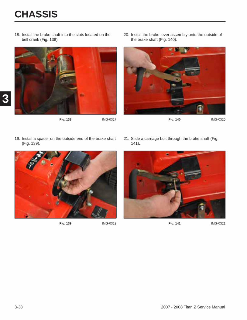
18. Install the brake shaft into the slots located on the bell crank (Fig. 138).
19. Install a spacer on the outside end of the brake shaft (Fig. 139).
21. Slide a carriage bolt through the brake shaft (Fig. 141).
20. Install the brake lever assembly onto the outside of the brake shaft (Fig. 140).
Fig. 138 IMG-0317
Fig. 139 IMG-0319
Fig. 140 IMG-0320
Fig. 141 IMG-0321
CHASSIS
3-392007 - 2008 Titan Z Service Manual
3
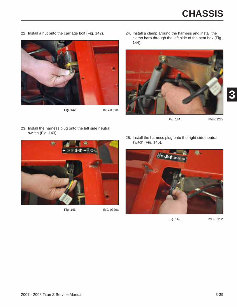
23. Install the harness plug onto the left side neutral switch (Fig. 143).
25. Install the harness plug onto the right side neutral switch (Fig. 145).
22. Install a nut onto the carriage bolt (Fig. 142). 24. Install a clamp around the harness and install the clamp barb through the left side of the seat box (Fig. 144).
Fig. 142 IMG-0323a
Fig. 143 IMG-0326a
Fig. 144 IMG-0327a
Fig. 145 IMG-0328a
CHASSIS
3-40 2007 - 2008 Titan Z Service Manual
3
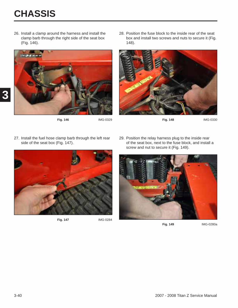
26. Install a clamp around the harness and install the clamp barb through the right side of the seat box (Fig. 146).
27. Install the fuel hose clamp barb through the left rear side of the seat box (Fig. 147).
29. Position the relay harness plug to the inside rear of the seat box, next to the fuse block, and install a screw and nut to secure it (Fig. 149).
28. Position the fuse block to the inside rear of the seat box and install two screws and nuts to secure it (Fig. 148).
Fig. 146 IMG-0329
Fig. 147 IMG-0284
Fig. 148 IMG-0330
Fig. 149 IMG-0280a

CHASSIS
3-412007 - 2008 Titan Z Service Manual
3
33. Route the PTO clutch wire through the hole in the frame in front of the engine (Fig. 153).
30. Install the relay into the harness plug (Fig. 150). 32. Pull the wire harness from inside the rear of the seat box assembly toward the outside through the thru hole. Install the rubber grommet into the thru hole to protect the wire harness (Fig. 152).
Fig. 150 IMG-0331
Fig. 152 IMG-0332a
Fig. 153 IMG-0338
31. Install two wire harness clamps that secure the wiring harness to the inside, rear of the seat box (Fig. 151).
Fig. 151 IMG-0283a

CHASSIS
3-42 2007 - 2008 Titan Z Service Manual
3
34. Plug the PTO clutch wire into the electric PTO clutch (Fig. 154).
35. Install a clamp securing the PTO clutch wire harness to the clutch anchor bracket (Fig. 155).
37. Install the violet wire connector to the alternator (red) wire (Fig. 157).
36. Install the blue harness wire to the oil sending
Fig. 154 IMG-0268a
Fig. 155 IMG-0342a
Fig. 156 IMG-0264a
Fig. 157 IMG-0260
CHASSIS
3-432007 - 2008 Titan Z Service Manual
3
39. Install the two ground wires to the engine base and install a nut to secure (Fig. 159).
38. Install the yellow/white wire plug into the grey/black wire plug that goes to the fuel solenoid and engine magneto (Fig. 158).
40. Position the solenoid to the back side of the seat box assembly. Install two bolts, washers, and nuts to secure it to the seat box assembly (Fig. 160).
Fig. 158 IMG-0258
Fig. 159 IMG-0257
Fig. 160 IMG-0254a
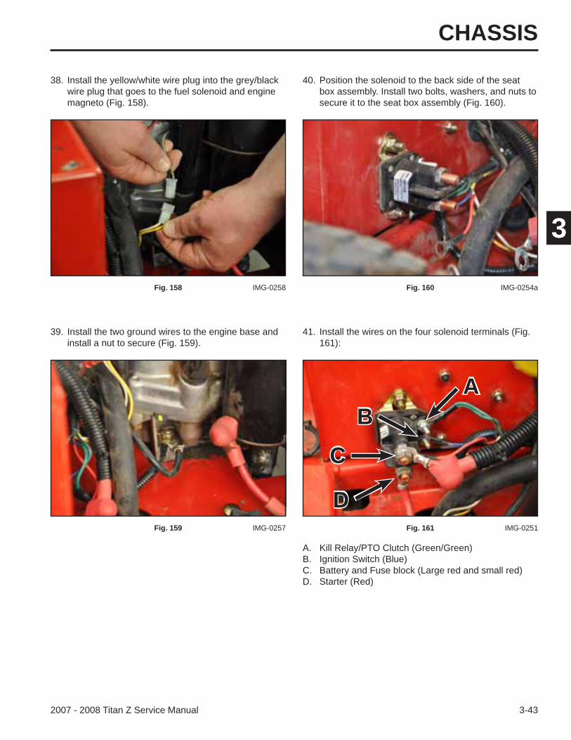
41. Install the wires on the four solenoid terminals (Fig. 161):
Fig. 161 IMG-0251
A. Kill Relay/PTO Clutch (Green/Green)B. Ignition Switch (Blue)C. Battery and Fuse block (Large red and small red)D. Starter (Red)
AB
C
D
CHASSIS
3-44 2007 - 2008 Titan Z Service Manual
3
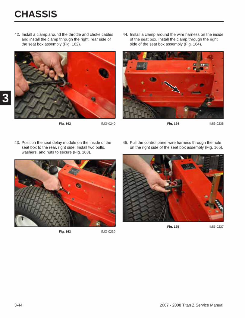
42. Install a clamp around the throttle and choke cables and install the clamp through the right, rear side of the seat box assembly (Fig. 162).
43. Position the seat delay module on the inside of the seat box to the rear, right side. Install two bolts, washers, and nuts to secure (Fig. 163).
45. Pull the control panel wire harness through the hole on the right side of the seat box assembly (Fig. 165).
44. Install a clamp around the wire harness on the inside of the seat box. Install the clamp through the right side of the seat box assembly (Fig. 164).
Fig. 162 IMG-0240
Fig. 163 IMG-0239
Fig. 164 IMG-0238
Fig. 165 IMG-0237
CHASSIS
3-452007 - 2008 Titan Z Service Manual
3
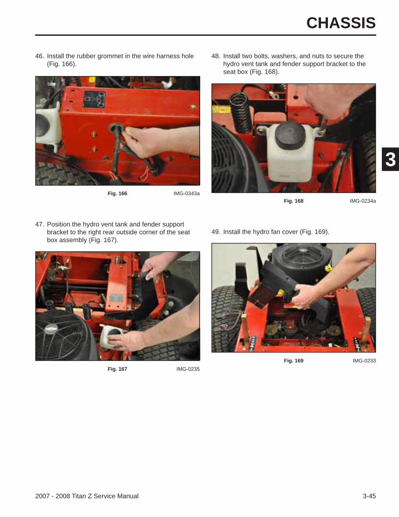
47. Position the hydro vent tank and fender support bracket to the right rear outside corner of the seat box assembly (Fig. 167).
49. Install the hydro fan cover (Fig. 169).
46. Install the rubber grommet in the wire harness hole (Fig. 166).
48. Install two bolts, washers, and nuts to secure the hydro vent tank and fender support bracket to the seat box (Fig. 168).
Fig. 166 IMG-0343a
Fig. 167 IMG-0235
Fig. 168 IMG-0234a
Fig. 169 IMG-0233
CHASSIS
3-46 2007 - 2008 Titan Z Service Manual
3
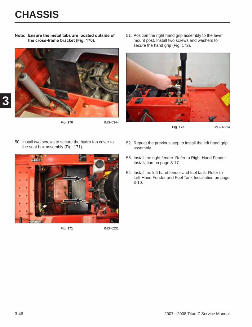
50. Install two screws to secure the hydro fan cover to the seat box assembly (Fig. 171).
52. Repeat the previous step to install the left hand grip assembly.
53. Install the right fender. Refer to Right Hand Fender Installation on page 3-17.
54. Install the left hand fender and fuel tank. Refer to Left Hand Fender and Fuel Tank Installation on page 3-10.
51. Position the right hand grip assembly to the lever mount post. Install two screws and washers to secure the hand grip (Fig. 172).
Fig. 170 IMG-0344
Fig. 171 IMG-0231
Fig. 172 IMG-0229a
CHASSIS
3-472007 - 2008 Titan Z Service Manual
3
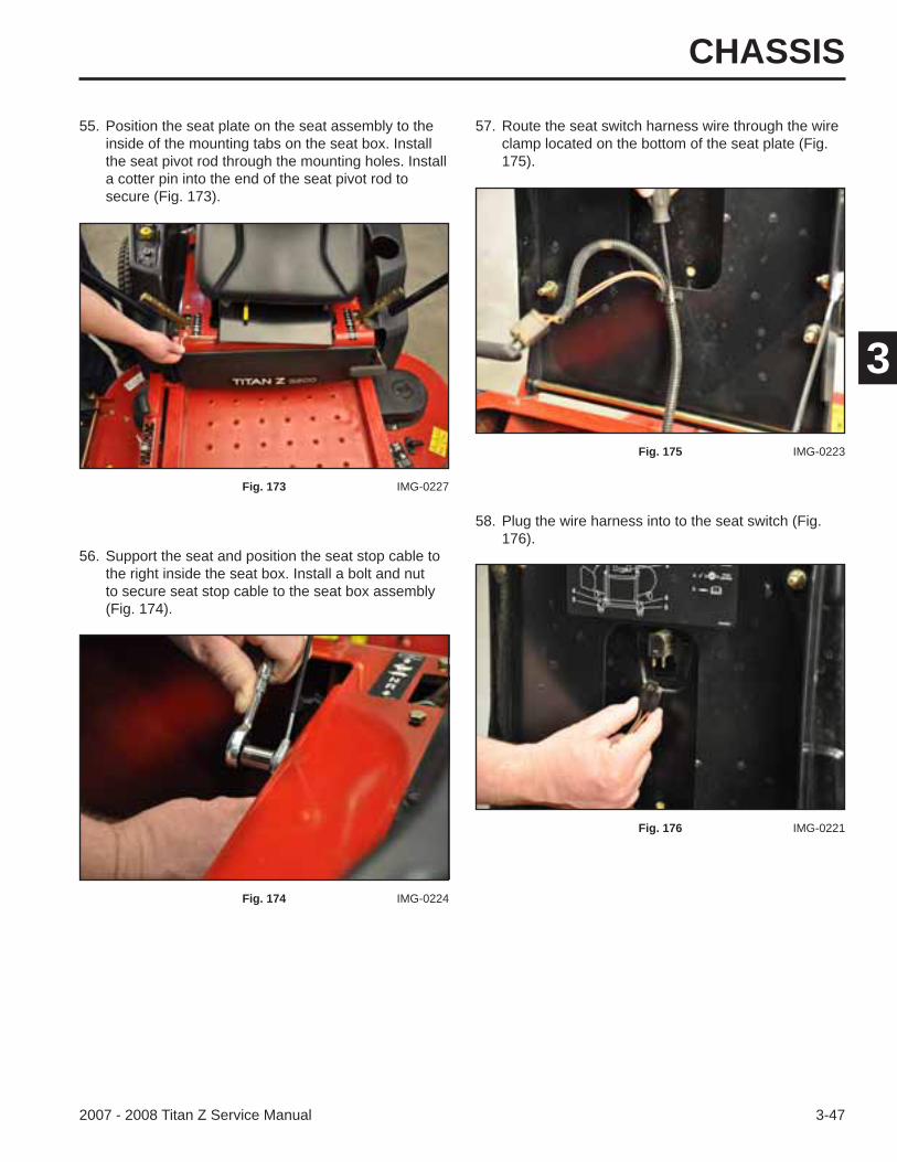
55. Position the seat plate on the seat assembly to the inside of the mounting tabs on the seat box. Install the seat pivot rod through the mounting holes. Install a cotter pin into the end of the seat pivot rod to secure (Fig. 173).
57. Route the seat switch harness wire through the wire clamp located on the bottom of the seat plate (Fig. 175).
Fig. 173 IMG-0227
56. Support the seat and position the seat stop cable to the right inside the seat box. Install a bolt and nut to secure seat stop cable to the seat box assembly (Fig. 174).
Fig. 174 IMG-0224
Fig. 175 IMG-0223
58. Plug the wire harness into to the seat switch (Fig. 176).
Fig. 176 IMG-0221
CHASSIS
3-48 2007 - 2008 Titan Z Service Manual
3
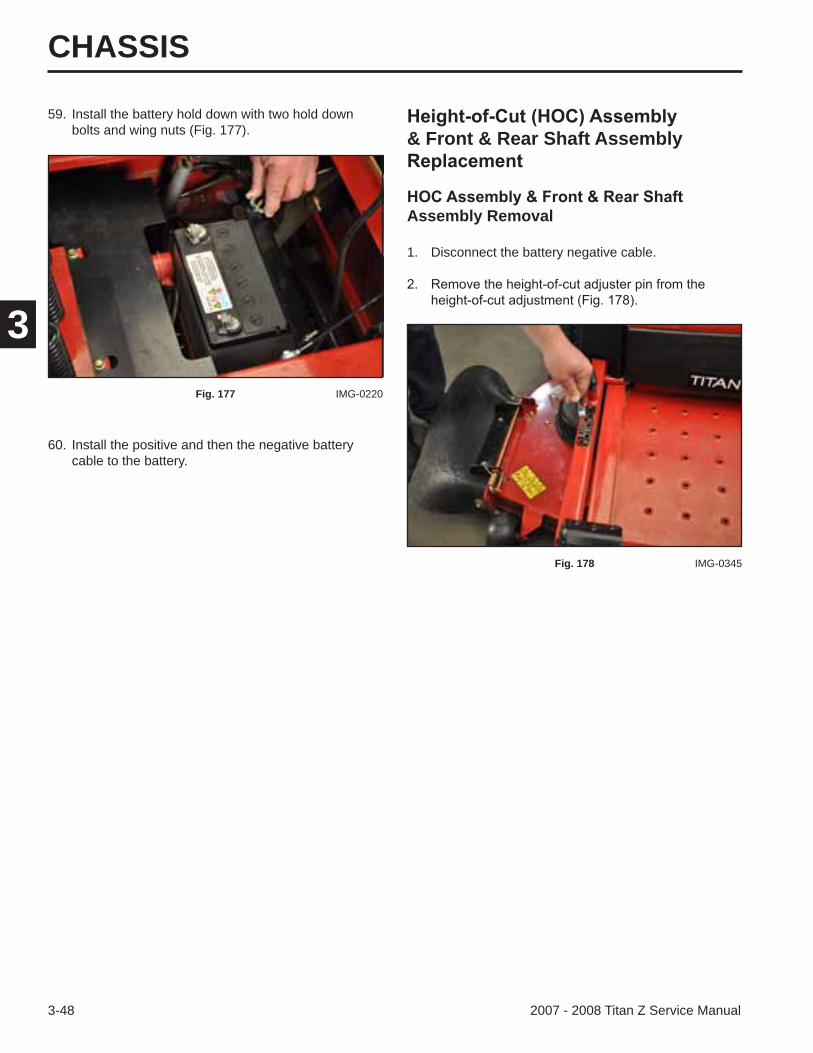
59. Install the battery hold down with two hold down bolts and wing nuts (Fig. 177).
60. Install the positive and then the negative battery cable to the battery.
Fig. 177 IMG-0220
& Front & Rear Shaft Assembly
Assembly Removal
1. Disconnect the battery negative cable.
Fig. 178 IMG-0345
CHASSIS
3-492007 - 2008 Titan Z Service Manual
3
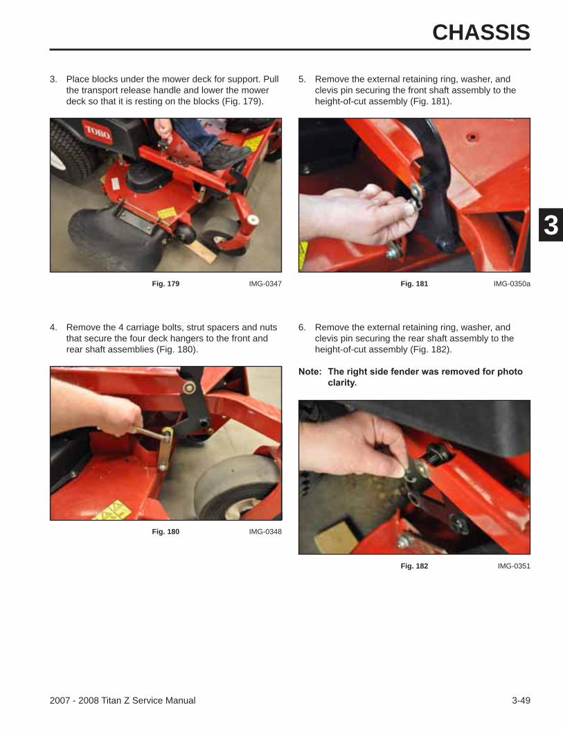
4. Remove the 4 carriage bolts, strut spacers and nuts that secure the four deck hangers to the front and rear shaft assemblies (Fig. 180).
3. Place blocks under the mower deck for support. Pull the transport release handle and lower the mower deck so that it is resting on the blocks (Fig. 179).
Fig. 179 IMG-0347
Fig. 180 IMG-0348
5. Remove the external retaining ring, washer, and clevis pin securing the front shaft assembly to the height-of-cut assembly (Fig. 181).
Fig. 181 IMG-0350a
6. Remove the external retaining ring, washer, and clevis pin securing the rear shaft assembly to the height-of-cut assembly (Fig. 182).
Fig. 182 IMG-0351
CHASSIS
3-50 2007 - 2008 Titan Z Service Manual
3
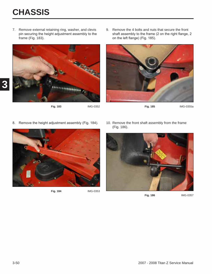
10. Remove the front shaft assembly from the frame (Fig. 186).
9. Remove the 4 bolts and nuts that secure the front
Fig. 185 IMG-0355a
Fig. 186 IMG-0357
7. Remove external retaining ring, washer, and clevis
frame (Fig. 183).
Fig. 183 IMG-0352
Fig. 184 IMG-0353
CHASSIS
3-512007 - 2008 Titan Z Service Manual
3
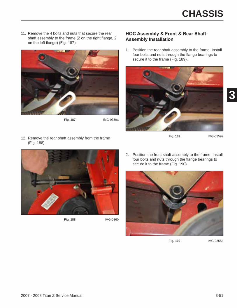
12. Remove the rear shaft assembly from the frame (Fig. 188).
11. Remove the 4 bolts and nuts that secure the rear
Fig. 187 IMG-0359a
Fig. 188 IMG-0360
Assembly Installation
1. Position the rear shaft assembly to the frame. Install
secure it to the frame (Fig. 189).
2. Position the front shaft assembly to the frame. Install
secure it to the frame (Fig. 190).
Fig. 189 IMG-0359a
Fig. 190 IMG-0355a
CHASSIS
3-52 2007 - 2008 Titan Z Service Manual
3
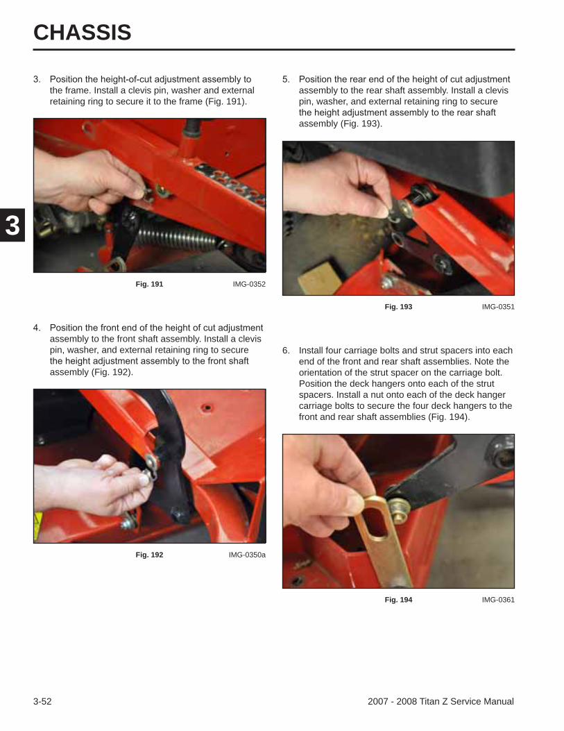
assembly to the rear shaft assembly. Install a clevis pin, washer, and external retaining ring to secure
assembly (Fig. 193).
Fig. 193 IMG-0351
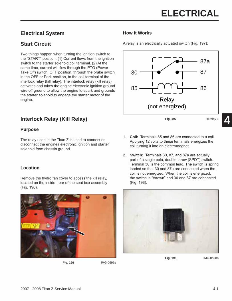
6. Install four carriage bolts and strut spacers into each end of the front and rear shaft assemblies. Note the orientation of the strut spacer on the carriage bolt. Position the deck hangers onto each of the strut spacers. Install a nut onto each of the deck hanger carriage bolts to secure the four deck hangers to the front and rear shaft assemblies (Fig. 194).
Fig. 194 IMG-0361
the frame. Install a clevis pin, washer and external retaining ring to secure it to the frame (Fig. 191).
Fig. 191 IMG-0352
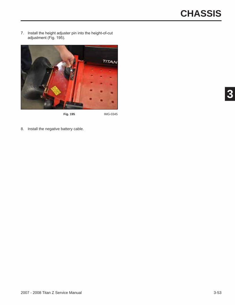
assembly to the front shaft assembly. Install a clevis pin, washer, and external retaining ring to secure
assembly (Fig. 192).
Fig. 192 IMG-0350a
CHASSIS
3-532007 - 2008 Titan Z Service Manual
3
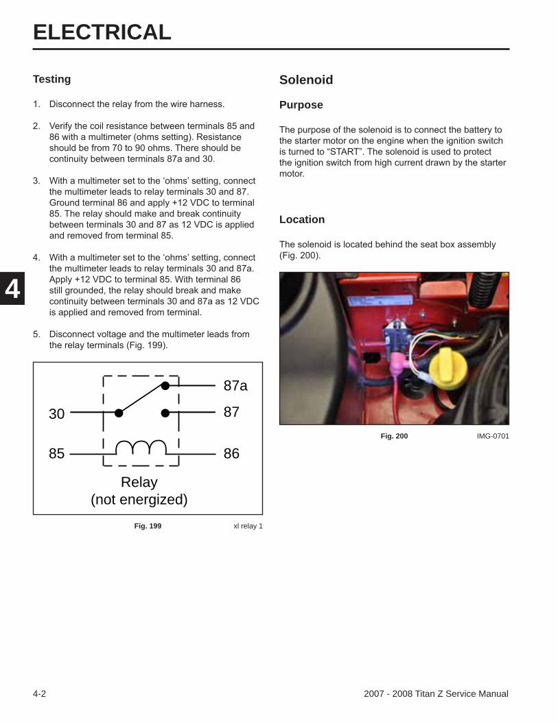
8. Install the negative battery cable.
Fig. 195 IMG-0345

CHASSIS
3-54 2007 - 2008 Titan Z Service Manual
3
ELECTRICAL
4-12007 - 2008 Titan Z Service Manual
4
Electrical System
Start Circuit
How It Works
Two things happen when turning the ignition switch to
activates and takes the engine electronic ignition ground
Interlock Relay (Kill Relay)
Purpose
The relay used in the Titan Z is used to connect or disconnect the engines electronic ignition and starter
30
85 86
87
87a
Relay(not energized)
Fig. 197 xl relay 1
Coil:
Switch:
Fig. 198
Location
Fig. 196
ELECTRICAL
4-2 2007 - 2008 Titan Z Service Manual
4
SolenoidTesting
Purpose
30
85 86
87
87a
Relay(not energized)
Fig. 199 xl relay 1
Location
Fig. 200 IMG-0701
ELECTRICAL
2007 - 2008 Titan Z Service Manual
4
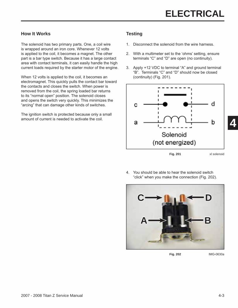
How It Works Testing
Fig. 201 xl solenoid
Fig. 202
A
C
B
D
ELECTRICAL
4-4 2007 - 2008 Titan Z Service Manual
4
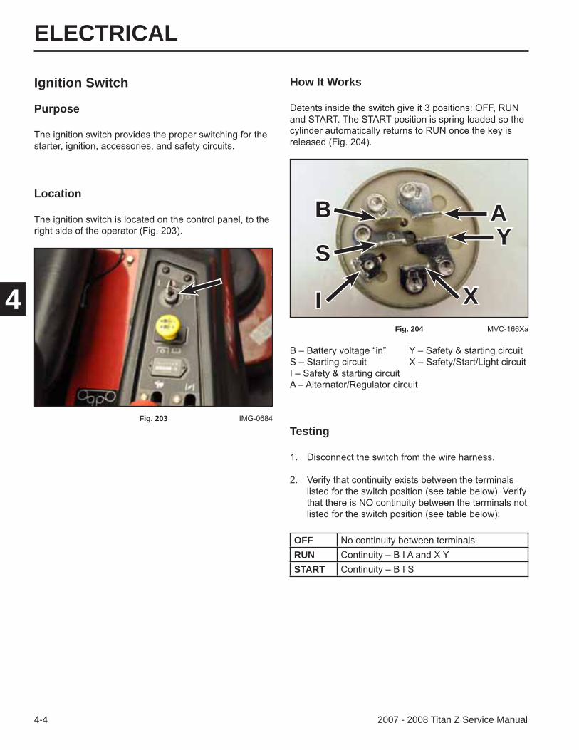
Ignition Switch
Purpose
How It Works
Testing
OFFRUNSTART
Fig. 204
Location
Fig. 203
AB
S
I
Y
X
ELECTRICAL
2007 - 2008 Titan Z Service Manual
4
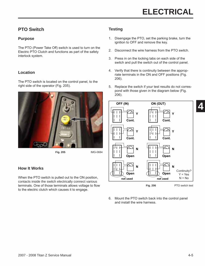
PTO Switch
Purpose
How It Works
contacts inside the switch electrically connect various
Testing
Fig. 206
Location
Fig. 205
Cont.
OFF (IN) ON (OUT)
not used
Cont.
Open
Open
Cont.
Cont.
Open
Opennot used
Y
Y
Y
Y
N
N
N
NContinuity?
ELECTRICAL
2007 - 2008 Titan Z Service Manual
4
Electric (PTO) Clutch How It Works
Purpose
so that it is not in contact with the clutch plate and is
Testing
Location
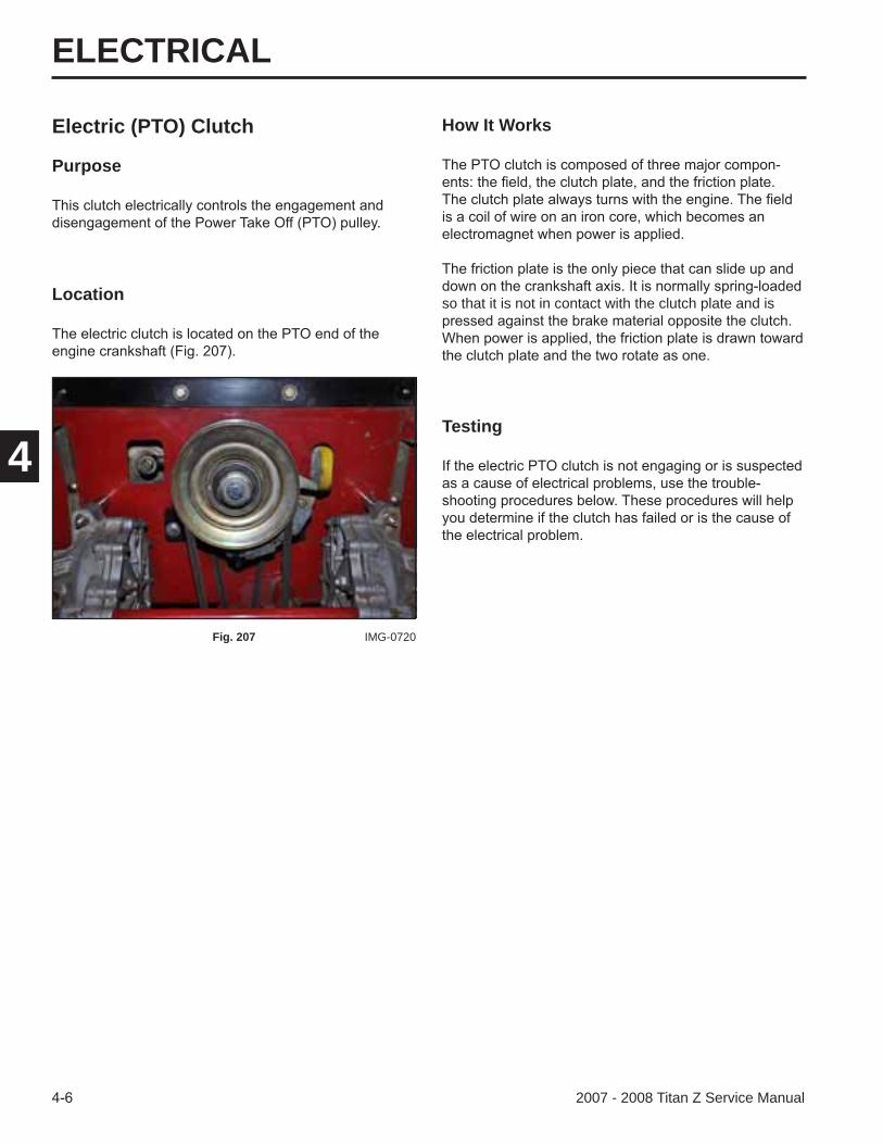
Fig. 207 IMG-0720
ELECTRICAL
4-72007 - 2008 Titan Z Service Manual
4
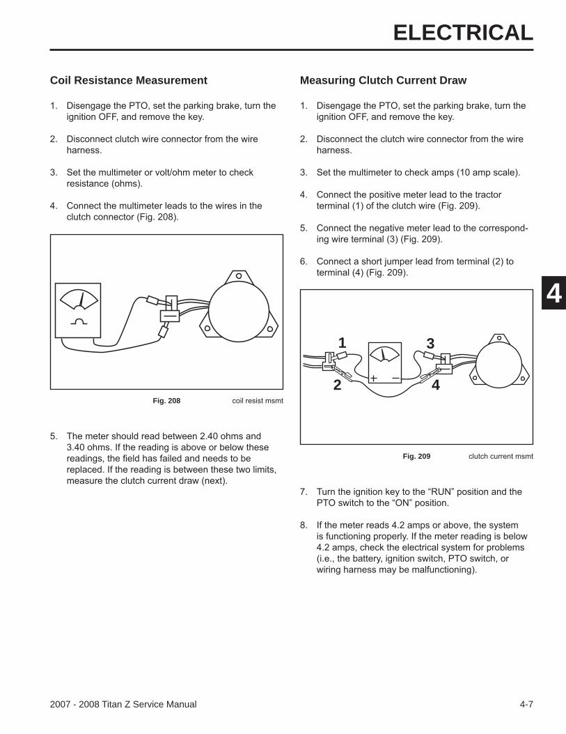
Coil Resistance Measurement Measuring Clutch Current Draw
1 3
42Fig. 208
Fig. 209
ELECTRICAL
4-8 2007 - 2008 Titan Z Service Manual
4
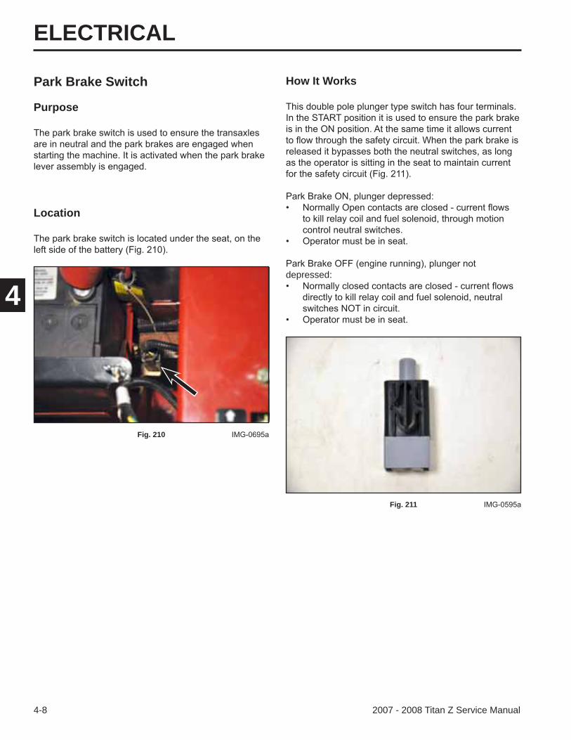
Park Brake Switch
Purpose
How It Works
depressed:
Fig. 211
Location
Fig. 210
ELECTRICAL
2007 - 2008 Titan Z Service Manual
4
Testing
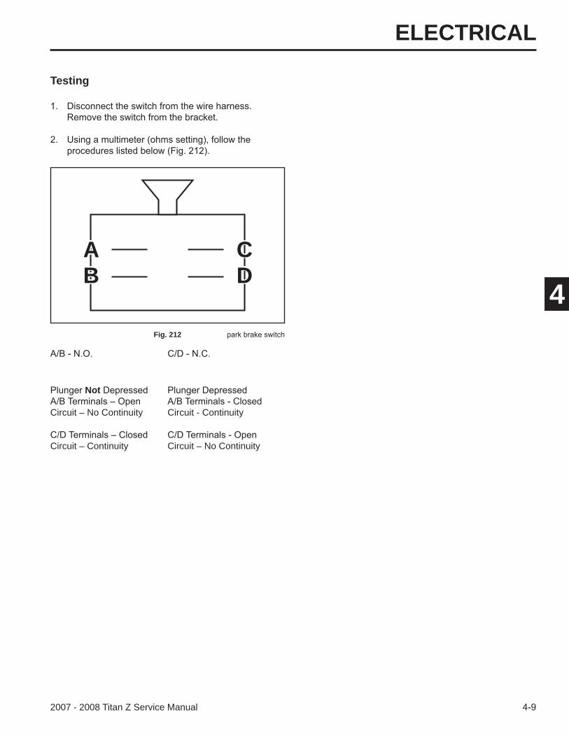
Fig. 212
Not
Circuit – No Continuity Circuit - Continuity
Circuit – Continuity Circuit – No Continuity
A CB D

ELECTRICAL
4-10 2007 - 2008 Titan Z Service Manual
4
How It Works
Testing
Fig. 214
Seat Switch
Purpose
running and the operator vacates the seat with either
Note: There is a delay module in the system (Briggs & Stratton Engines only) that causes a slight delay between the moment the operator vacates the seat and the engine shuts down.
Location
Fig. 213
ELECTRICAL
4-112007 - 2008 Titan Z Service Manual
4
How It Works
Testing
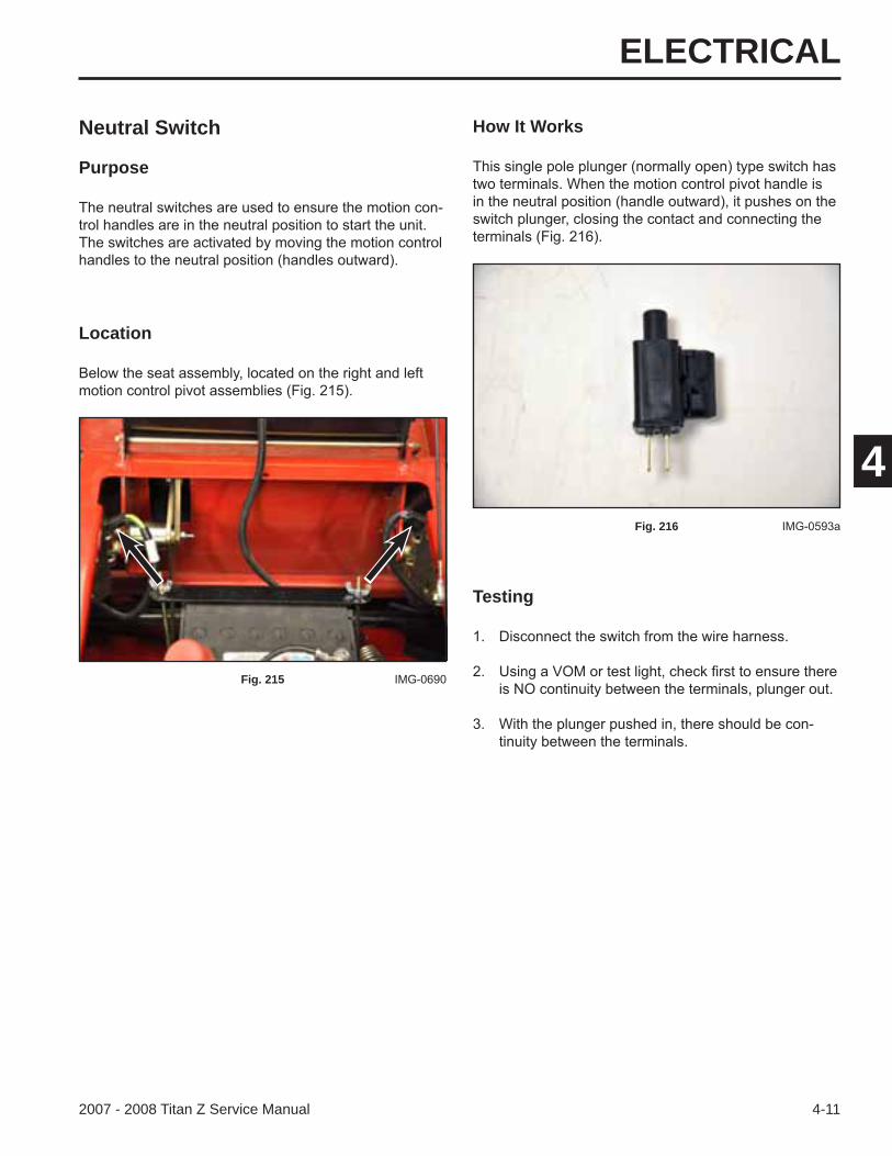
Neutral Switch
Purpose
Fig. 216
Location
Fig. 215
ELECTRICAL
4-12 2007 - 2008 Titan Z Service Manual
4
How It Works
Testing
Fig. 218
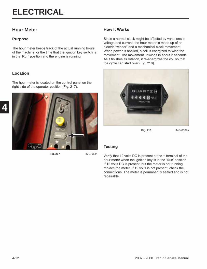
Hour Meter
Purpose
Location
Fig. 217
ELECTRICAL
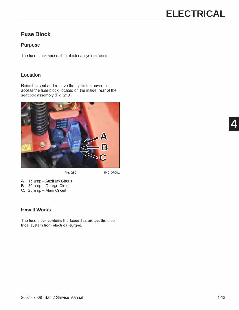
2007 - 2008 Titan Z Service Manual
4
Fuse Block
Purpose
How It Works
Fig. 219 IMG-0700a
Location
ABC
ELECTRICAL
4-14 2007 - 2008 Titan Z Service Manual
4
Seat Delay Module (Briggs & Stratton models only)
Purpose
How It Works
the seat switch circuit to keep the engine running in case
Location
Fig. 220
Fig. 221
ELECTRICAL
2007 - 2008 Titan Z Service Manual
4
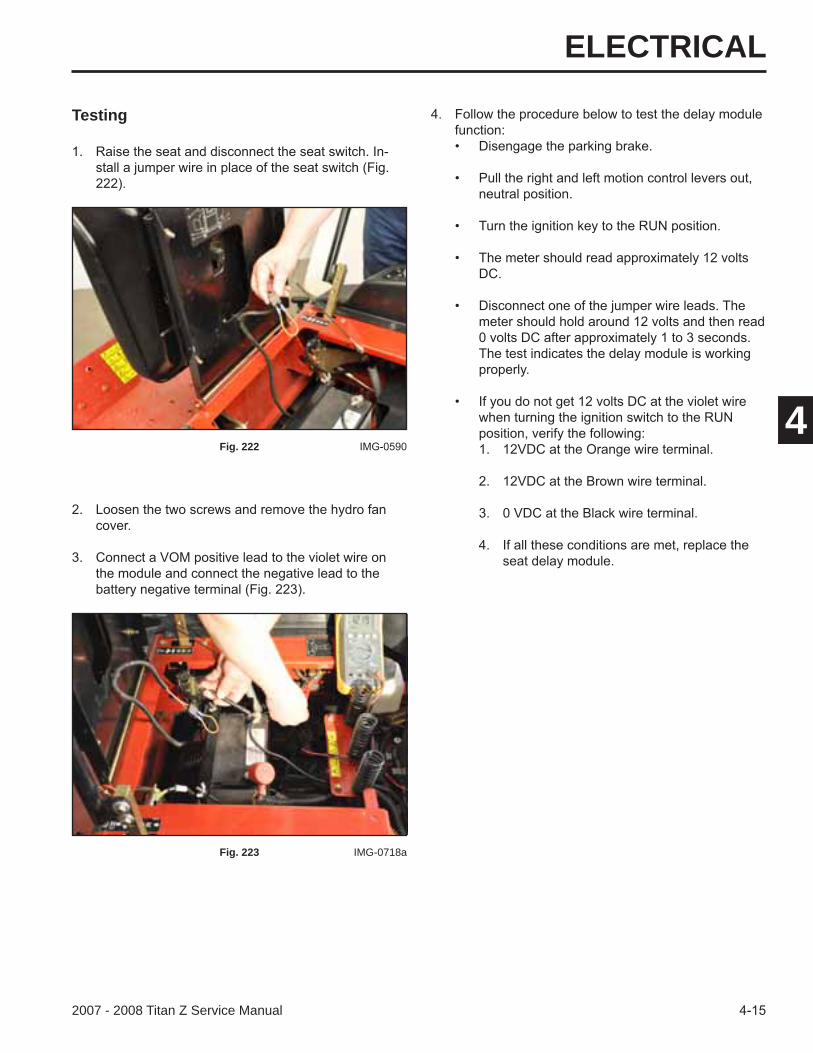
Testing
Fig. 222
Fig. 223 IMG-0718a
ELECTRICAL
2007 - 2008 Titan Z Service Manual
4
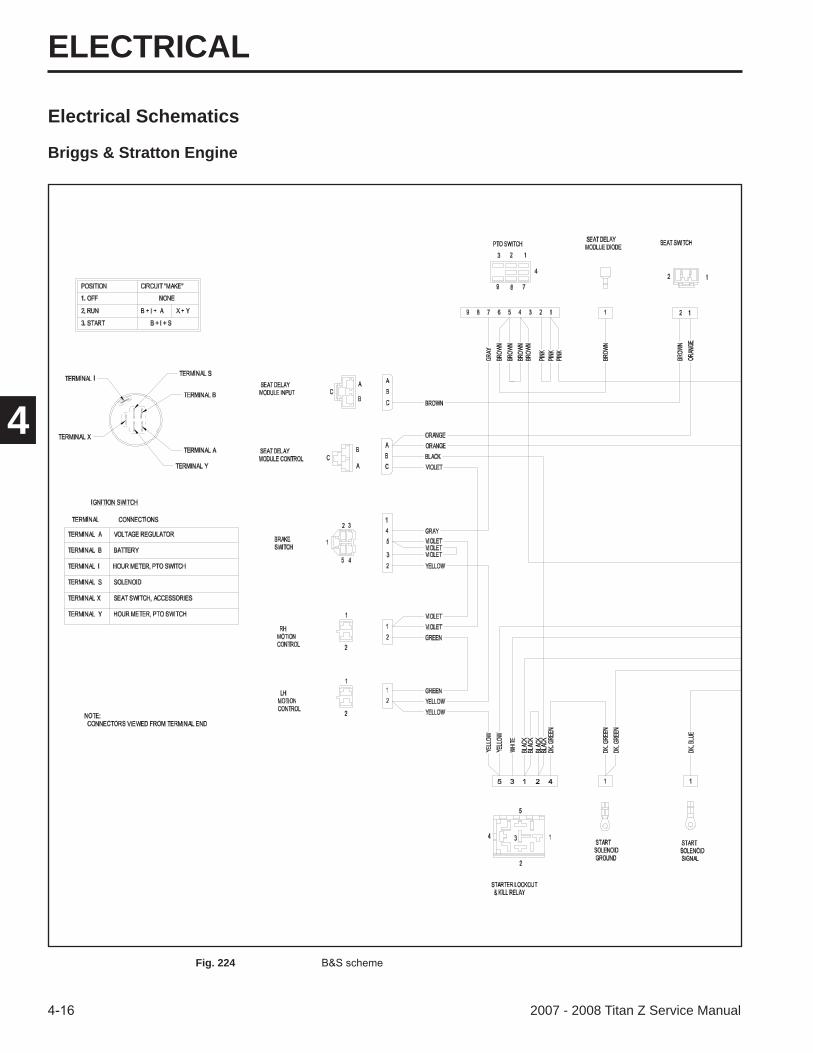
Electrical Schematics
Briggs & Stratton Engine
Fig. 224
ELECTRICAL
4-172007 - 2008 Titan Z Service Manual
4
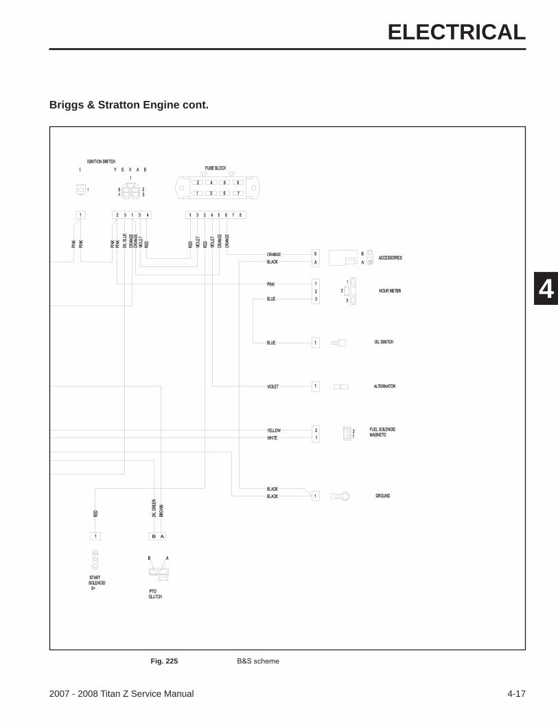
Briggs & Stratton Engine cont.
Fig. 225
ELECTRICAL
4-18 2007 - 2008 Titan Z Service Manual
4
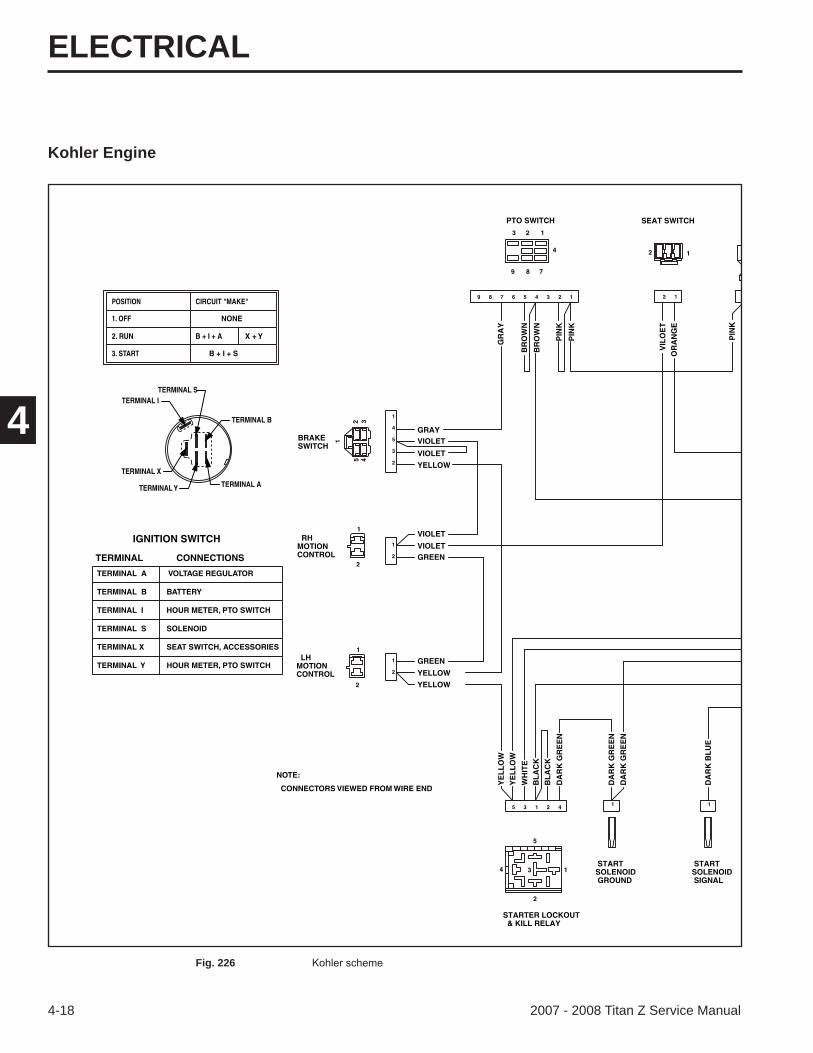
Kohler Engine
TERMINAL ITERMINAL S
TERMINAL X
TERMINAL Y
TERMINAL B
TERMINAL A
3. START
POSITION
1. OFF
2. RUN
B + I + S
CIRCUIT "MAKE"
X + Y
NONE
B + I + A
IGNITION SWITCH
TERMINAL CONNECTIONS
TERMINAL A VOLTAGE REGULATOR
TERMINAL B BATTERY
TERMINAL I HOUR METER, PTO SWITCH
TERMINAL S SOLENOID
TERMINAL X SEAT SWITCH, ACCESSORIES
TERMINAL Y HOUR METER, PTO SWITCH
CONNECTORS VIEWED FROM WIRE END
NOTE:
BRAKESWITCH
RHMOTIONCONTROL
LHMOTIONCONTROL
STARTER LOCKOUT & KILL RELAY
STARTSOLENOID GROUND
STARTSOLENOID SIGNAL
SEAT SWITCHPTO SWITCH
OR
AN
GE
PIN
K
PIN
K
PIN
K
PIN
K
DA
RK
BL
UE
BL
AC
K
BL
AC
K
DA
RK
GR
EE
N
DA
RK
GR
EE
N
DA
RK
GR
EE
N
BR
OW
N
GR
AY
BR
OW
N
YELLOW
YELLOW
YELLOW
GREEN
GREEN
VIOLET
VIOLET
VIOLET
VIOLET
GRAY
VIL
OE
T
2
3
5
4
1
2
1
2
1
42135 1 1
2 19 8 7 6 5 4 3 2 1
1
2 345
2
1
2 1
4
9 8 7
3
12
2
1
1
2
34
5
YE
LL
OW
WH
ITE
YE
LL
OW
Fig. 226
ELECTRICAL
2007 - 2008 Titan Z Service Manual
4
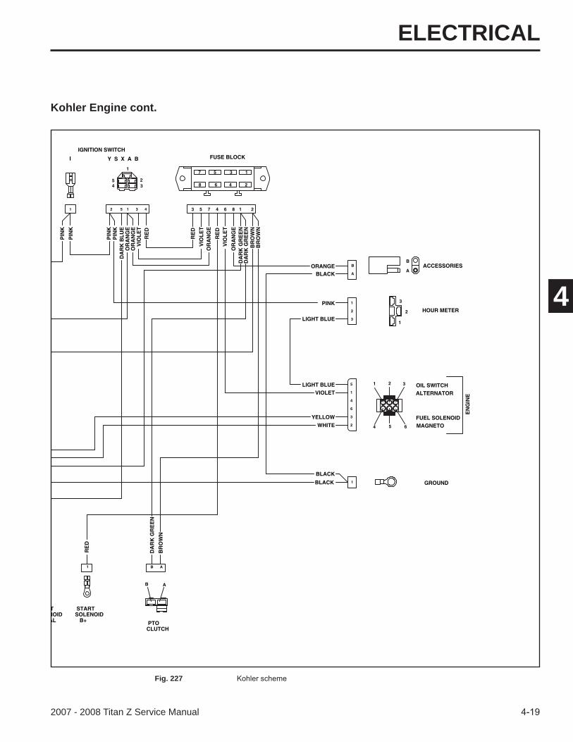
Kohler Engine cont.
FUEL SOLENOID
TNOIDAL
STARTSOLENOID B+ PTO
CLUTCH
GROUND
ALTERNATOROIL SWITCH
HOUR METER
ACCESSORIES
FUSE BLOCKIGNITION SWITCH
OR
AN
GE
OR
AN
GE
OR
AN
GE
OR
AN
GE
DA
RK
GR
EE
ND
AR
K G
RE
EN
BR
OW
NB
RO
WN
VIO
LE
T
VIO
LE
T
VIO
LE
T
RE
D
RE
D
RE
D
Y S X A BI
ORANGEBLACK
PINK
LIGHT BLUE
LIGHT BLUE
PIN
K
PIN
K
PIN
KP
INK
RE
D
VIOLET
YELLOWWHITE MAGNETO
EN
GIN
E
BR
OW
N
DA
RK
GR
EE
N
1 AB
1
1
2
3
3 5 7 4 6 8 1 22 5 1 3 41
B
A
5
1
4
6
3
2
B A
4 5 6
1 2 3
1
2
3
A
B
1
2
3
4
5
6
7
8
1
234
5
BLACK
BLACK
DA
RK
BL
UE
Fig. 227

ELECTRICAL
4-20 2007 - 2008 Titan Z Service Manual
4 THIS PAGE INTENTIONALLY LEFT BLANK.
MOWER DECK
5-12007 - 2008 Titan Z Service Manual
5
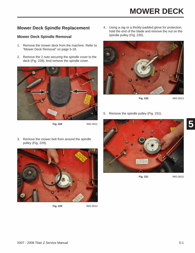
Mower Deck Spindle Replacement
Mower Deck Spindle Removal
3. Remove the mower belt from around the spindle pulley (Fig. 229).
1. Remove the mower deck from the machine. Refer to “Mower Deck Removal” on page 5-18.
2. Remove the 2 nuts securing the spindle cover to the deck (Fig. 228). And remove the spindle cover.
4. Using a rag or a thickly-padded glove for protection, hold the end of the blade and remove the nut on the spindle pulley (Fig. 230).
Fig. 228 IMG-0611
Fig. 229 IMG-0612
Fig. 230 IMG-0613
5. Remove the spindle pulley (Fig. 231).
Fig. 231 IMG-0615
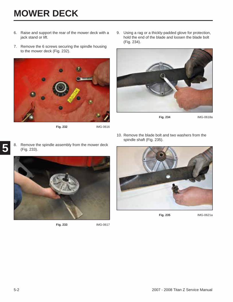
MOWER DECK
5-2 2007 - 2008 Titan Z Service Manual
5 8. Remove the spindle assembly from the mower deck (Fig. 233).
10. Remove the blade bolt and two washers from the spindle shaft (Fig. 235).
9. Using a rag or a thickly-padded glove for protection, hold the end of the blade and loosen the blade bolt (Fig. 234).
Fig. 232 IMG-0616
Fig. 233 IMG-0617
Fig. 234 IMG-0618a
Fig. 235 IMG-0621a
6. Raise and support the rear of the mower deck with a jack stand or lift.
7. Remove the 6 screws securing the spindle housing to the mower deck (Fig. 232).
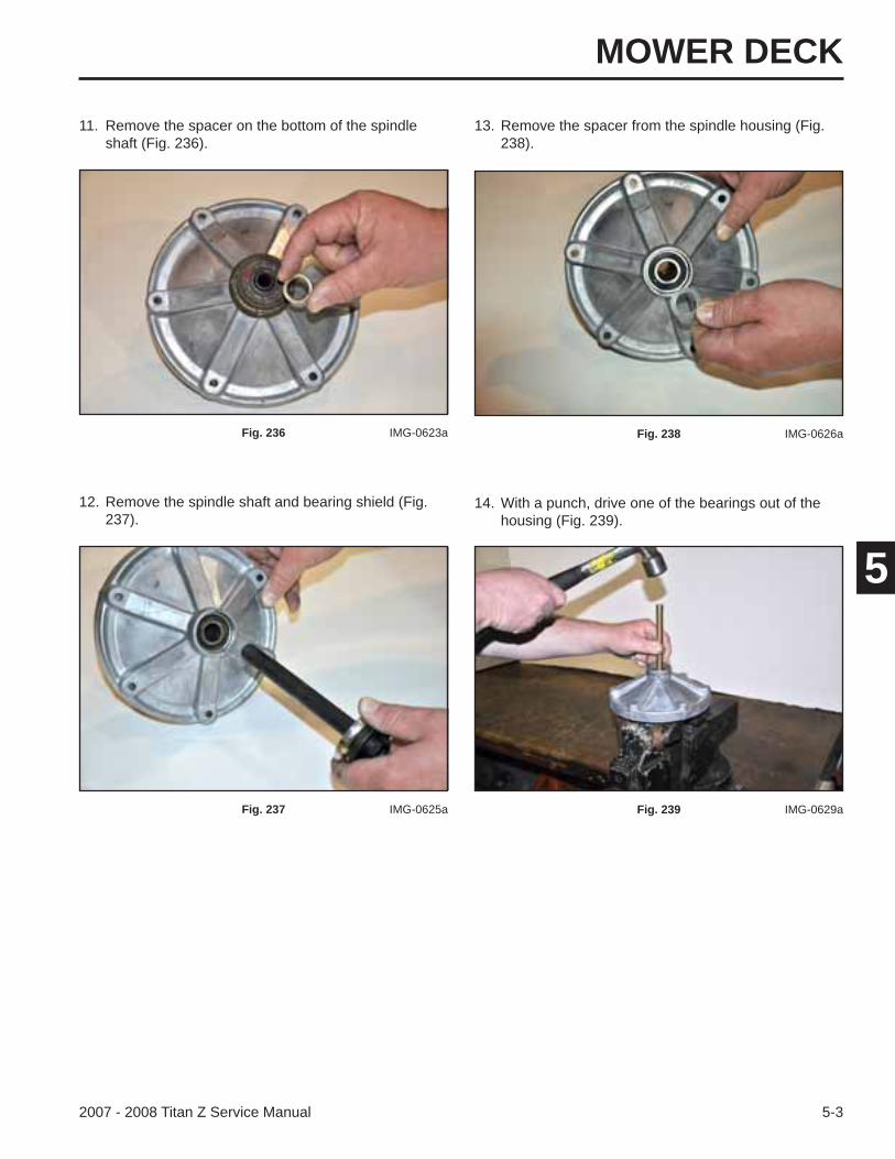
MOWER DECK
5-32007 - 2008 Titan Z Service Manual
5
12. Remove the spindle shaft and bearing shield (Fig. 237).
14. With a punch, drive one of the bearings out of the housing (Fig. 239).
11. Remove the spacer on the bottom of the spindle shaft (Fig. 236).
13. Remove the spacer from the spindle housing (Fig. 238).
Fig. 236 IMG-0623a
Fig. 237 IMG-0625a
Fig. 238 IMG-0626a
Fig. 239 IMG-0629a
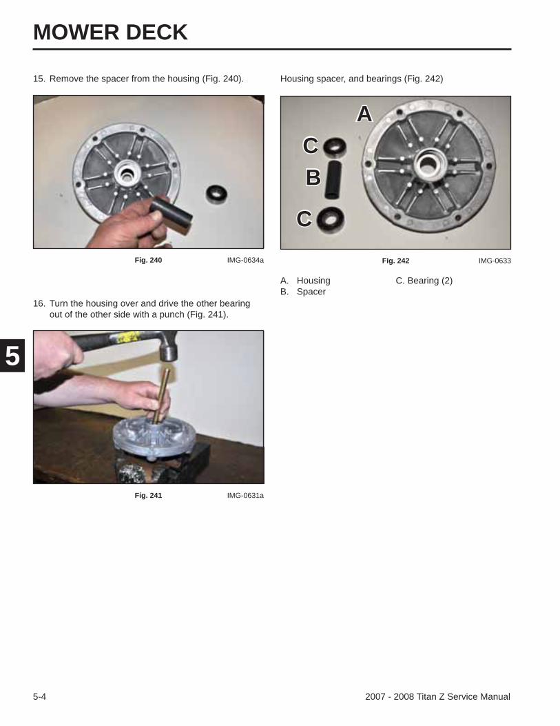
MOWER DECK
5-4 2007 - 2008 Titan Z Service Manual
5
15. Remove the spacer from the housing (Fig. 240).
16. Turn the housing over and drive the other bearing out of the other side with a punch (Fig. 241).
A. Housing C. Bearing (2)B. Spacer
Housing spacer, and bearings (Fig. 242)
Fig. 240 IMG-0634a
Fig. 241 IMG-0631a
Fig. 242 IMG-0633
AC
C
B
MOWER DECK
5-52007 - 2008 Titan Z Service Manual
5
Mower Deck Spindle Installation
2. Turn the spindle housing over and install the spacer into the housing (Fig. 244).
1. Tap a bearing into the blade end of the housing until it seats (Fig. 243).
3. Tap the second bearing into the pulley side of the spindle housing until it seats (Fig. 245).
Fig. 243 IMG-0636a
Fig. 244 IMG-0637a
Fig. 245 IMG-0638a
4. With the bearing shield and spacer installed on the spindle shaft, install the spindle shaft into the spindle housing (Fig. 246).
Fig. 246 IMG-0639a
MOWER DECK
5-6 2007 - 2008 Titan Z Service Manual
5
5. Place a spacer onto the spindle shaft (Fig. 247).
6. Position the mower blade onto the spindle shaft and spacer (Fig. 248).
7. With two washers on the blade bolt, install the blade bolt and two washers into the spindle shaft (Fig. 249).
Fig. 247 IMG-0650a
Fig. 248 IMG-0647a
Fig. 249 IMG-0648
8. Torque the blade bolt to 37 ± 5 ft-lbs. (50 + 6.8 Nm) to secure the blade.
9. Position the spindle assembly to the inside of the mower deck (Fig. 250).
Fig. 250 IMG-0617
MOWER DECK
5-72007 - 2008 Titan Z Service Manual
513. Route the mower deck belt around the spindle pulley
(Fig. 254).
10. Install 6 screws to secure the spindle assembly to the mower deck. Torque the 6 screws to 200 – 250 in-lbs. (16.7 – 20.8 Nm) (Fig. 251).
12. Install the spindle pulley nut. Torque the spindle pulley nut to 50 ft-lbs (67.8 Nm) (Fig. 253).
Fig. 251 IMG-0651aFig. 253 IMG-0653
Fig. 254 IMG-0654
11. Install the spindle pulley onto the spindle shaft. The side of the pulley with the large hub should face toward the spindle housing (Fig. 252).
Fig. 252 IMG-0652a
MOWER DECK
5-8 2007 - 2008 Titan Z Service Manual
5
Idler Arm Assembly Replacement
Idler Arm Assembly Removal
3. Remove the other end of the spring extension from the idler arm (Fig. 258).
Fig. 258 IMG-0656a
14. Check that the mower deck belt is routed properly. Refer to the belt routing decal (Fig. 255):
16. Install the mower deck to the machine. Refer to “Mower Deck Installation” on page 5-19.
1. Remove the mower deck from the machine. Refer to “Mower Deck Removal” on page 5-18.
2. With a spring tool (Toro part number 92-5771) remove the extension spring from the spring post located at the rear of the mower deck (Fig. 257).
Fig. 255 109-6035
Fig. 257 IMG-0655
15. Position the belt cover onto the mower deck. Install two nuts to secure (Fig. 256).
Fig. 256 IMG-0611
MOWER DECK
5-92007 - 2008 Titan Z Service Manual
5
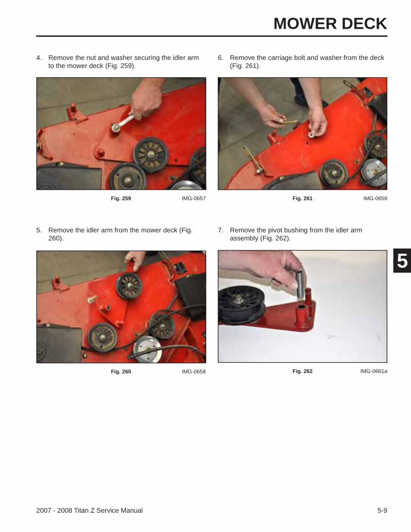
4. Remove the nut and washer securing the idler arm to the mower deck (Fig. 259).
6. Remove the carriage bolt and washer from the deck (Fig. 261).
Fig. 259 IMG-0657
5. Remove the idler arm from the mower deck (Fig. 260).
Fig. 260 IMG-0658
Fig. 261 IMG-0659
7. Remove the pivot bushing from the idler arm assembly (Fig. 262).
Fig. 262 IMG-0661a
MOWER DECK
5-10 2007 - 2008 Titan Z Service Manual
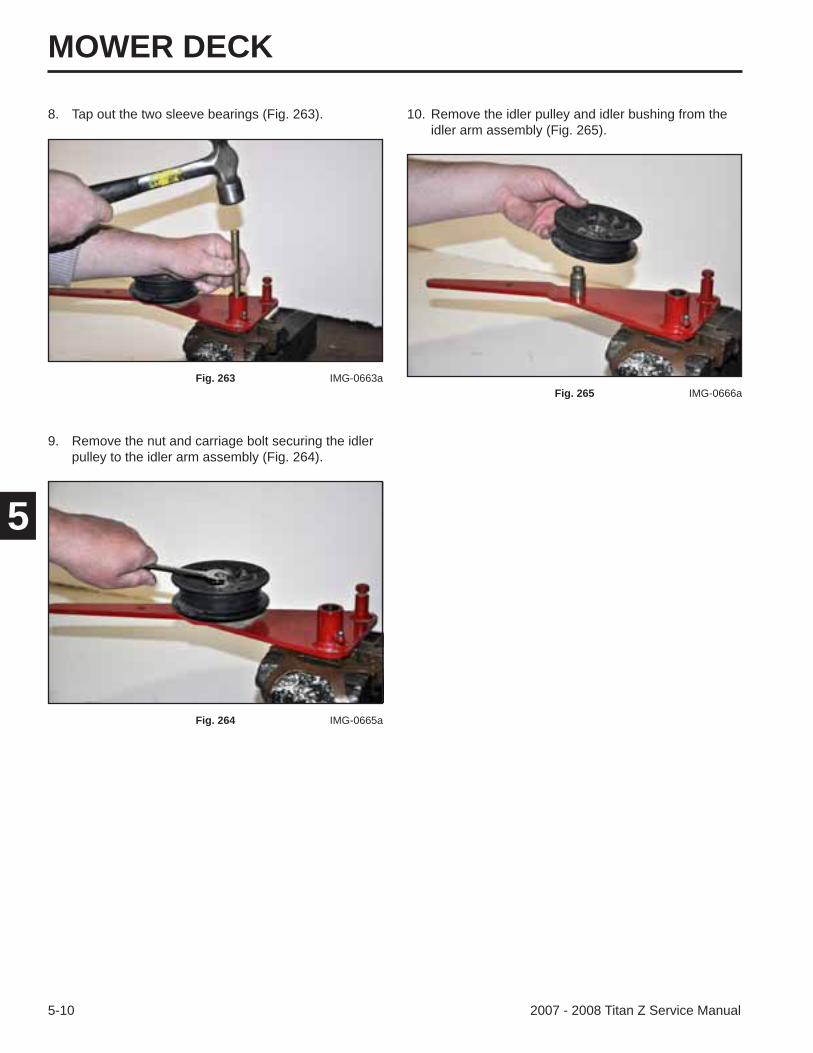
5
10. Remove the idler pulley and idler bushing from the idler arm assembly (Fig. 265).
Fig. 265 IMG-0666a
9. Remove the nut and carriage bolt securing the idler pulley to the idler arm assembly (Fig. 264).
8. Tap out the two sleeve bearings (Fig. 263).
Fig. 263 IMG-0663a
Fig. 264 IMG-0665a
MOWER DECK
5-112007 - 2008 Titan Z Service Manual
5
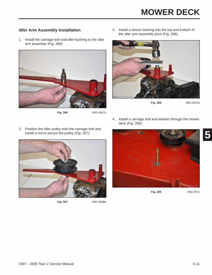
Idler Arm Assembly Installation
2. Position the idler pulley onto the carriage bolt and install a nut to secure the pulley (Fig. 267).
1. Install the carriage bolt and idler bushing to the idler arm assembly (Fig. 266).
Fig. 266 IMG-0667a
Fig. 267 IMG-0668a
3. Install a sleeve bearing into the top and bottom of the idler arm assembly pivot (Fig. 268).
4. Install a carriage bolt and washer through the mower deck (Fig. 269).
Fig. 268 IMG-0670a
Fig. 269 IMG-0671
MOWER DECK
5-12 2007 - 2008 Titan Z Service Manual
5273).
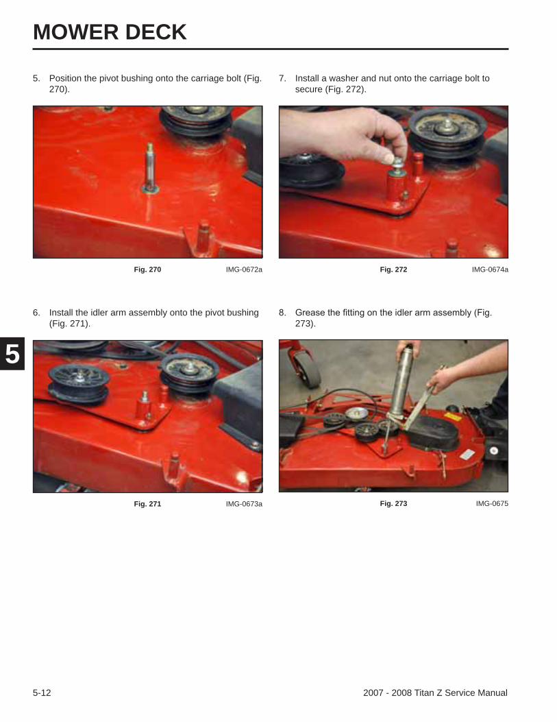
7. Install a washer and nut onto the carriage bolt to secure (Fig. 272).
Fig. 272 IMG-0674a
Fig. 273 IMG-0675
5. Position the pivot bushing onto the carriage bolt (Fig. 270).
Fig. 270 IMG-0672a
6. Install the idler arm assembly onto the pivot bushing (Fig. 271).
Fig. 271 IMG-0673a
MOWER DECK
5-132007 - 2008 Titan Z Service Manual
5
9. Install the extension spring on the idler arm as-sembly post (Fig. 274).
Fig. 274 IMG-0656a
10. Using a spring tool (Toro part number 92-5771), install the other end of the extension spring onto the spring post located at the rear of the mower deck (Fig. 275).
Fig. 275 IMG-0655
11. Install the mower deck onto the machine. Refer to “Mower Deck Installation” on page 5-19.
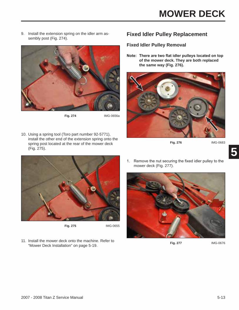
Fixed Idler Pulley Replacement
Fixed Idler Pulley Removal
of the mower deck. They are both replaced the same way (Fig. 276).
mower deck (Fig. 277).
Fig. 276 IMG-0683
Fig. 277 IMG-0676
MOWER DECK
5-14 2007 - 2008 Titan Z Service Manual
5
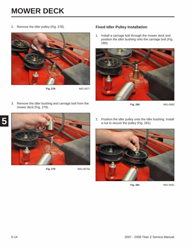
Fixed Idler Pulley Installation
1. Install a carriage bolt through the mower deck and position the idler bushing onto the carriage bolt (Fig. 280).
Fig. 280 IMG-0680
2. Position the idler pulley onto the idler bushing. Install a nut to secure the pulley (Fig. 281).
Fig. 281 IMG-0681
3. Remove the idler bushing and carriage bolt from the mower deck (Fig. 279).
2. Remove the idler pulley (Fig. 278).
Fig. 278 IMG-0677
Fig. 279 IMG-0679a
MOWER DECK
5-152007 - 2008 Titan Z Service Manual
5
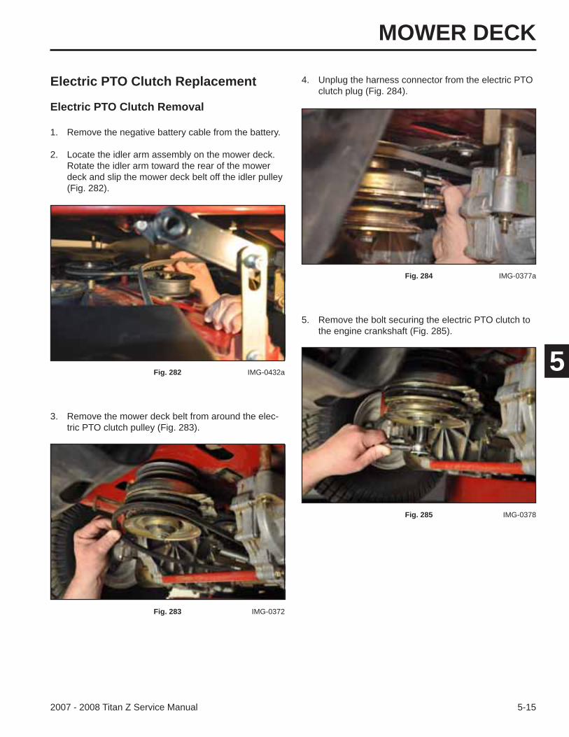
1. Remove the negative battery cable from the battery.
2. Locate the idler arm assembly on the mower deck. Rotate the idler arm toward the rear of the mower deck and slip the mower deck belt off the idler pulley (Fig. 282).
Fig. 282 IMG-0432a
3. Remove the mower deck belt from around the elec-tric PTO clutch pulley (Fig. 283).
Fig. 283 IMG-0372
Electric PTO Clutch Replacement
Electric PTO Clutch Removal
4. Unplug the harness connector from the electric PTO clutch plug (Fig. 284).
5. Remove the bolt securing the electric PTO clutch to the engine crankshaft (Fig. 285).
Fig. 284 IMG-0377a
Fig. 285 IMG-0378
MOWER DECK
5-16 2007 - 2008 Titan Z Service Manual
5
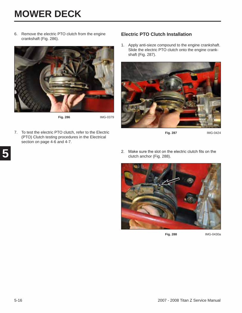
Electric PTO Clutch Installation
1. Apply anti-sieze compound to the engine crankshaft.Slide the electric PTO clutch onto the engine crank-shaft (Fig. 287).
Fig. 287 IMG-0424
clutch anchor (Fig. 288).
Fig. 288 IMG-0430a
7. To test the electric PTO clutch, refer to the Electric (PTO) Clutch testing procedures in the Electrical section on page 4-6 and 4-7.
6. Remove the electric PTO clutch from the engine crankshaft (Fig. 286).
Fig. 286 IMG-0379
MOWER DECK
5-172007 - 2008 Titan Z Service Manual
5
3. With 3 washers installed on the electric PTO clutch bolt, apply thread locking compound to the threads of the clutch bolt (Fig. 289).
Fig. 289 IMG-0429a
4. Install the clutch bolt, 2 spring washers, and washer to the crankshaft. Torque the clutch bolt to 55 ft-lbs. (74.6 Nm).
5. Plug the harness plug into the electric PTO clutch plug (Fig. 290).
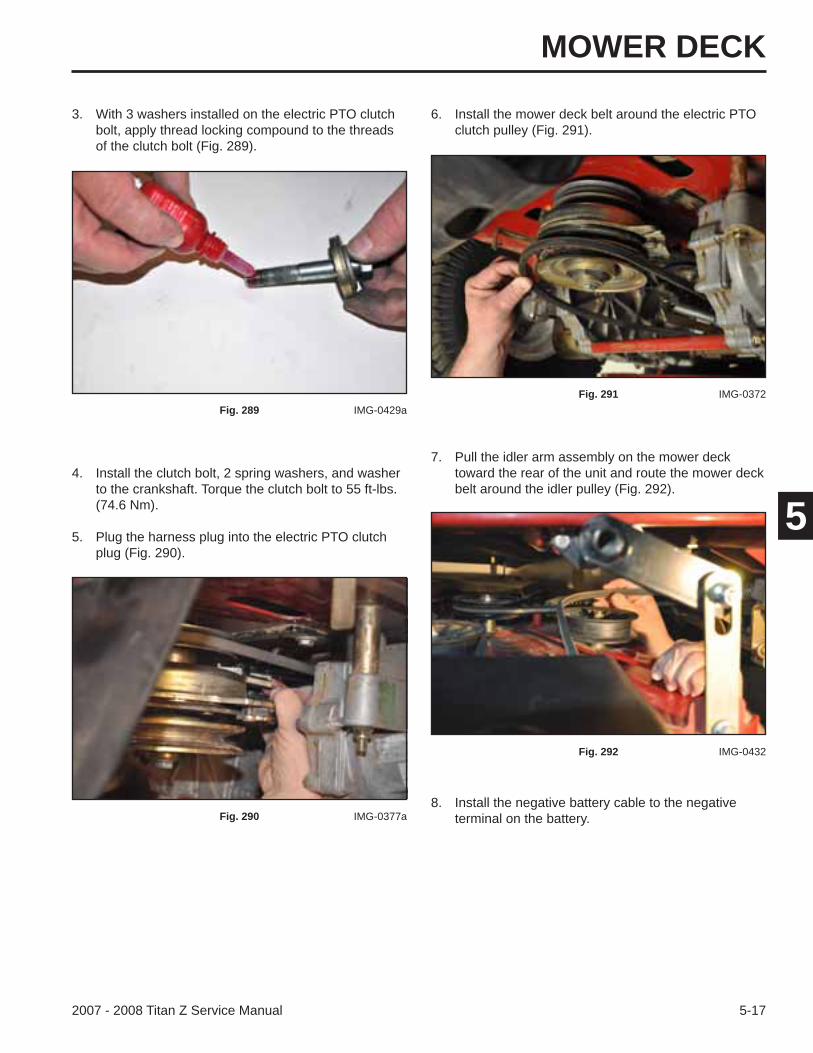
Fig. 290 IMG-0377a
6. Install the mower deck belt around the electric PTO clutch pulley (Fig. 291).
7. Pull the idler arm assembly on the mower deck toward the rear of the unit and route the mower deck belt around the idler pulley (Fig. 292).
Fig. 291 IMG-0372
Fig. 292 IMG-0432
8. Install the negative battery cable to the negative terminal on the battery.
MOWER DECK
5-18 2007 - 2008 Titan Z Service Manual
5
Mower Deck Replacement
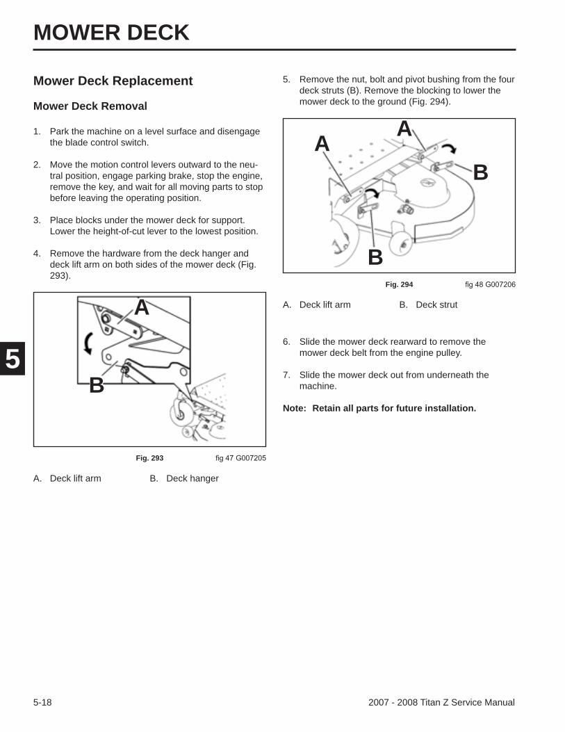
Mower Deck Removal
6. Slide the mower deck rearward to remove the mower deck belt from the engine pulley.
7. Slide the mower deck out from underneath the machine.
Note: Retain all parts for future installation.
A. Deck lift arm B. Deck strut
5. Remove the nut, bolt and pivot bushing from the four deck struts (B). Remove the blocking to lower the mower deck to the ground (Fig. 294).
A. Deck lift arm B. Deck hanger
Fig. 294
1. Park the machine on a level surface and disengage the blade control switch.
2. Move the motion control levers outward to the neu-tral position, engage parking brake, stop the engine, remove the key, and wait for all moving parts to stop before leaving the operating position.
3. Place blocks under the mower deck for support. Lower the height-of-cut lever to the lowest position.
4. Remove the hardware from the deck hanger and deck lift arm on both sides of the mower deck (Fig. 293).
Fig. 293
A
B
AA
B
B

MOWER DECK
5-192007 - 2008 Titan Z Service Manual
5
Mower Deck Installation
A. Deck lift arm B. Deck strut
1. Park the machine on a level surface and disengage the blade control switch.
2. Move the motion control levers outward to the neutral position, engage parking brake, stop the engine, remove the key, and wait for all moving parts to stop before leaving the operation position.
3. Slide the mower deck under the machine.
4. Lower the height-of-cut lever to the lowest position.
5. Use the existing hardware to attach the rear deck strut of the mower to the deck lift arm (Fig. 295).
Fig. 295
AA
B
B
6. Attach the hardware from the deck hanger and deck lift arm on both sides of the deck (Fig. 296).
8. Make sure the mower deck is level side-to-side, and front-to-back. Refer to “Leveling the Mower Deck” and “Adjusting the Blade Slope” (next).
A. Deck lift arm B. Deck hanger
Fig. 296
A
B
7. Route the mower deck belt around the engine pulley and check the routing of the mower deck belt on the mower deck (Fig. 297):
Fig. 297 109-6035
MOWER DECK
5-20 2007 - 2008 Titan Z Service Manual
5
6. Check the front-to-rear blade level any time you install the mower. If the front blade tip is not 1/16 – 5/16” (1.6 – 7.9mm) lower than the rear blade tip, adjust the blade level. Refer to “Adjusting the Blade Slope” next.
7. Set the anti-scalp rollers to top holes or remove them completely for this adjustment.
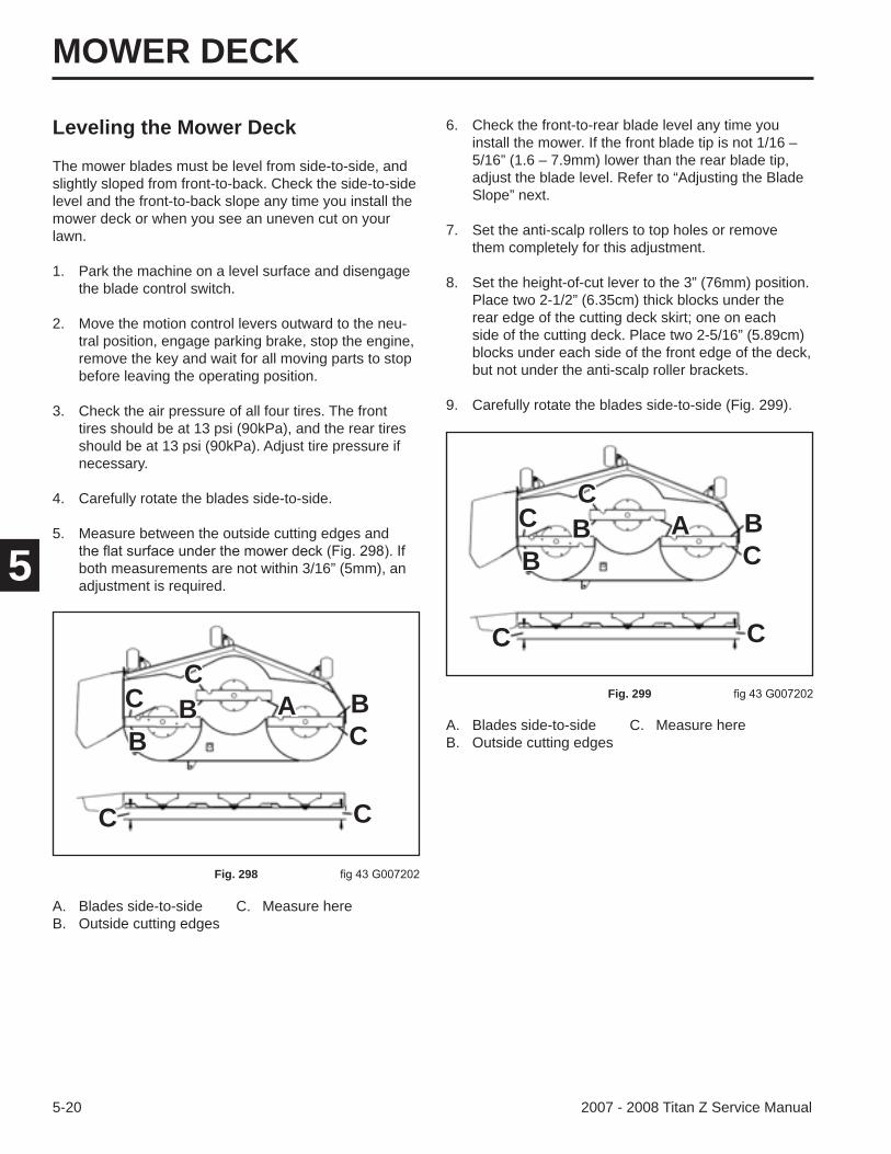
8. Set the height-of-cut lever to the 3” (76mm) position. Place two 2-1/2” (6.35cm) thick blocks under the rear edge of the cutting deck skirt; one on each side of the cutting deck. Place two 2-5/16” (5.89cm) blocks under each side of the front edge of the deck, but not under the anti-scalp roller brackets.
9. Carefully rotate the blades side-to-side (Fig. 299).
A. Blades side-to-side C. Measure hereB. Outside cutting edges
A. Blades side-to-side C. Measure hereB. Outside cutting edges
Fig. 299
Leveling the Mower Deck
The mower blades must be level from side-to-side, and slightly sloped from front-to-back. Check the side-to-side level and the front-to-back slope any time you install the mower deck or when you see an uneven cut on your lawn.
1. Park the machine on a level surface and disengage the blade control switch.
2. Move the motion control levers outward to the neu-tral position, engage parking brake, stop the engine, remove the key and wait for all moving parts to stop before leaving the operating position.
3. Check the air pressure of all four tires. The front tires should be at 13 psi (90kPa), and the rear tires should be at 13 psi (90kPa). Adjust tire pressure if necessary.
4. Carefully rotate the blades side-to-side.
5. Measure between the outside cutting edges and
both measurements are not within 3/16” (5mm), an adjustment is required.
Fig. 298
A BBB
C
C
C
CC
A BBB
C
C
C
CC
MOWER DECK
5-212007 - 2008 Titan Z Service Manual
5
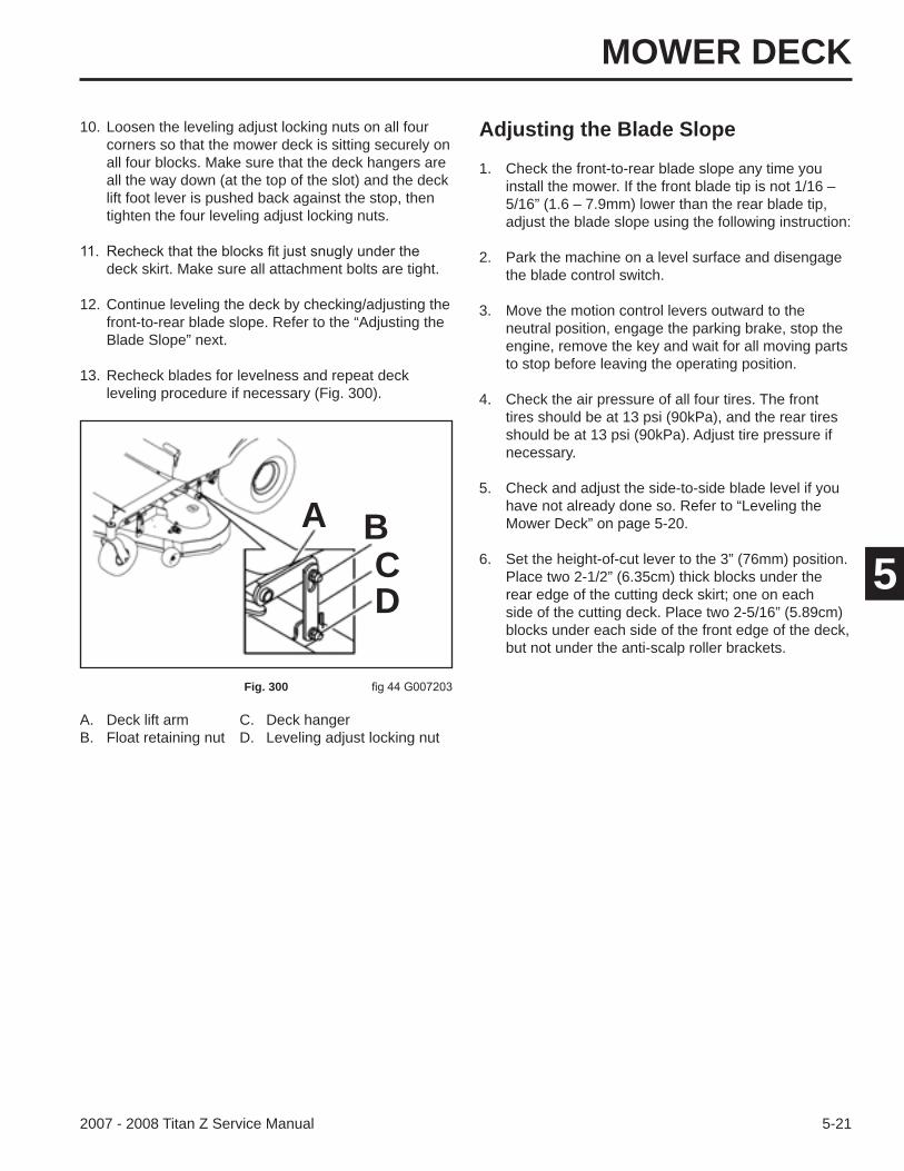
10. Loosen the leveling adjust locking nuts on all four corners so that the mower deck is sitting securely on all four blocks. Make sure that the deck hangers are all the way down (at the top of the slot) and the deck lift foot lever is pushed back against the stop, then tighten the four leveling adjust locking nuts.
deck skirt. Make sure all attachment bolts are tight.
12. Continue leveling the deck by checking/adjusting the front-to-rear blade slope. Refer to the “Adjusting the Blade Slope” next.
13. Recheck blades for levelness and repeat deck leveling procedure if necessary (Fig. 300).
Fig. 300
A BCD
A. Deck lift arm C. Deck hangerB. Float retaining nut D. Leveling adjust locking nut
Adjusting the Blade Slope
1. Check the front-to-rear blade slope any time you install the mower. If the front blade tip is not 1/16 – 5/16” (1.6 – 7.9mm) lower than the rear blade tip, adjust the blade slope using the following instruction:
2. Park the machine on a level surface and disengage the blade control switch.
3. Move the motion control levers outward to the neutral position, engage the parking brake, stop the engine, remove the key and wait for all moving parts to stop before leaving the operating position.
4. Check the air pressure of all four tires. The front tires should be at 13 psi (90kPa), and the rear tires should be at 13 psi (90kPa). Adjust tire pressure if necessary.
5. Check and adjust the side-to-side blade level if you have not already done so. Refer to “Leveling the Mower Deck” on page 5-20.
6. Set the height-of-cut lever to the 3” (76mm) position. Place two 2-1/2” (6.35cm) thick blocks under the rear edge of the cutting deck skirt; one on each side of the cutting deck. Place two 2-5/16” (5.89cm) blocks under each side of the front edge of the deck, but not under the anti-scalp roller brackets.
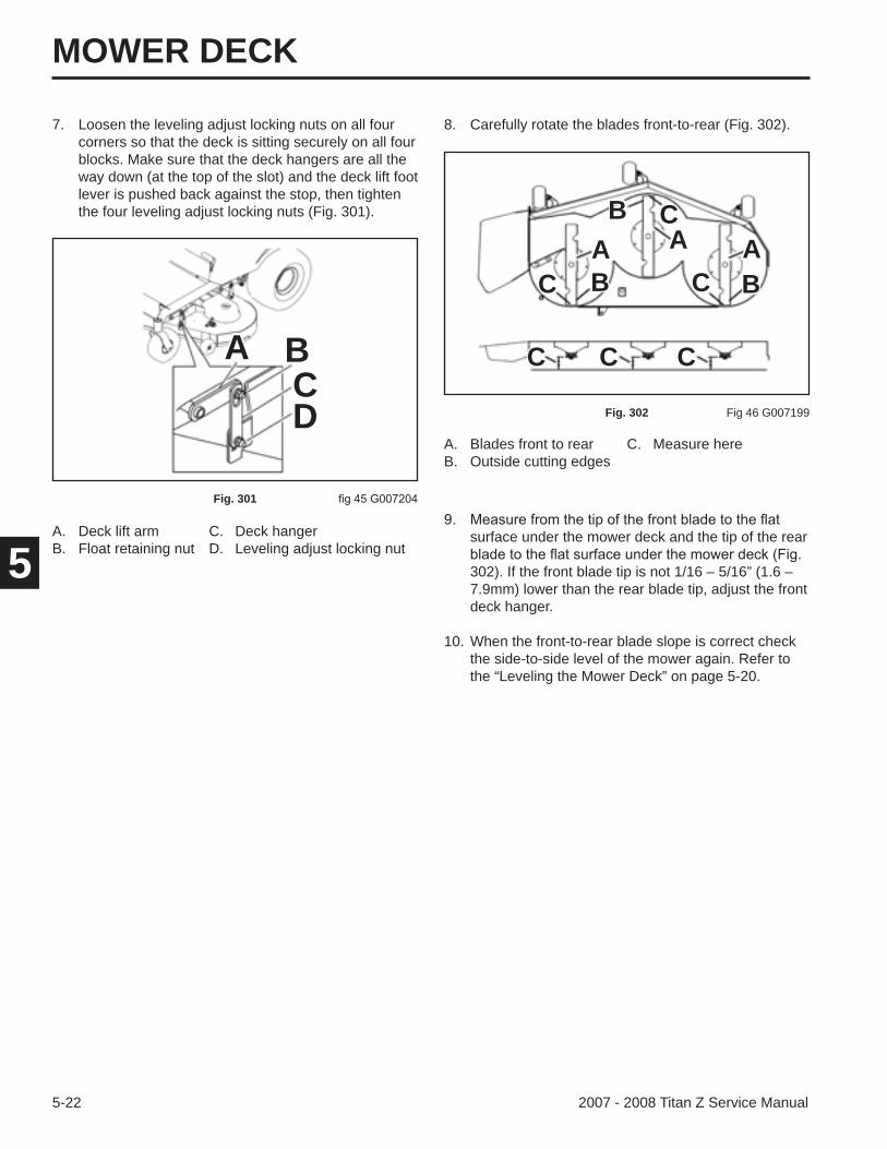
MOWER DECK
5-22 2007 - 2008 Titan Z Service Manual
5surface under the mower deck and the tip of the rear
302). If the front blade tip is not 1/16 – 5/16” (1.6 – 7.9mm) lower than the rear blade tip, adjust the front deck hanger.
10. When the front-to-rear blade slope is correct check the side-to-side level of the mower again. Refer to the “Leveling the Mower Deck” on page 5-20.
A. Blades front to rear C. Measure hereB. Outside cutting edges
8. Carefully rotate the blades front-to-rear (Fig. 302).
Fig. 302 Fig 46 G007199
A. Deck lift arm C. Deck hangerB. Float retaining nut D. Leveling adjust locking nut
7. Loosen the leveling adjust locking nuts on all four corners so that the deck is sitting securely on all four blocks. Make sure that the deck hangers are all the way down (at the top of the slot) and the deck lift foot lever is pushed back against the stop, then tighten the four leveling adjust locking nuts (Fig. 301).
Fig. 301
A BCD
A A AB
B
B C
C
C
C C C
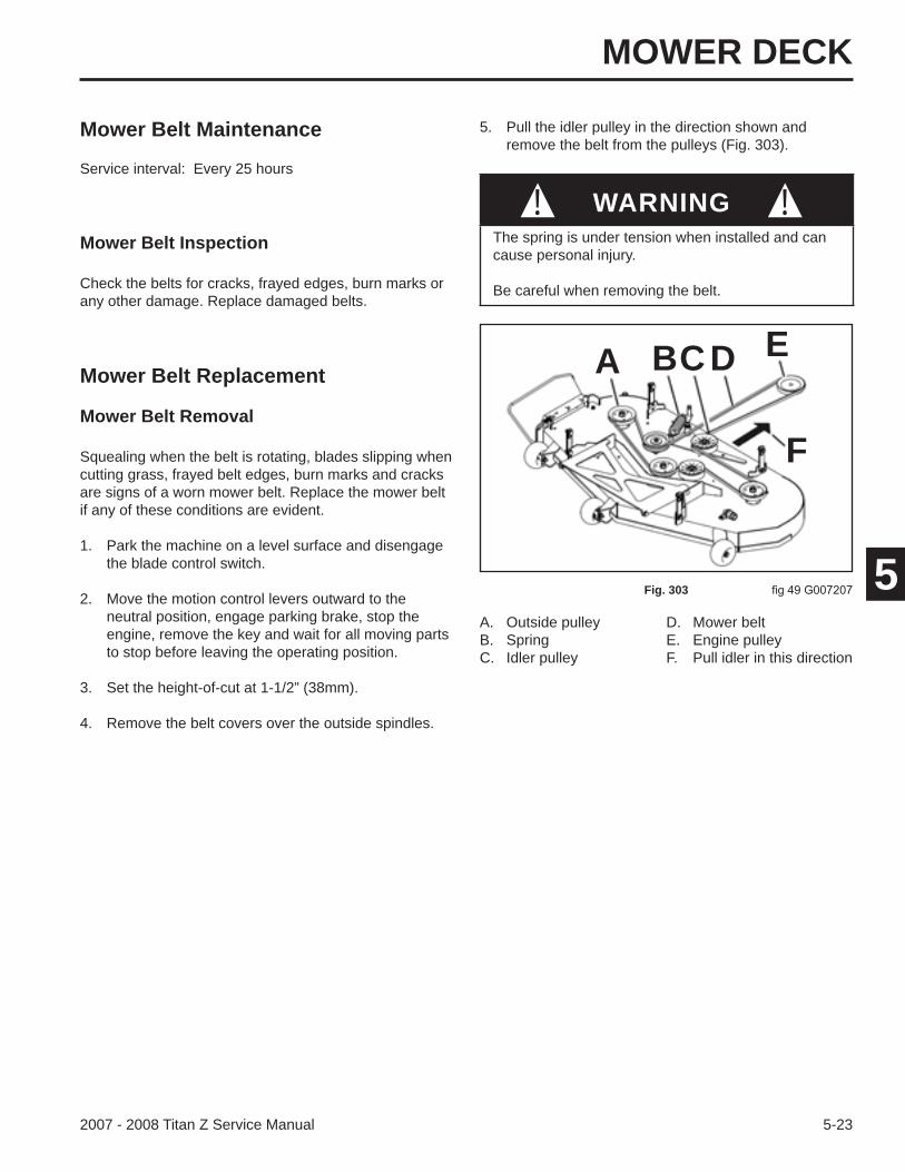
MOWER DECK
5-232007 - 2008 Titan Z Service Manual
5
Mower Belt Maintenance
Mower Belt Inspection
Mower Belt Replacement
Mower Belt Removal
Squealing when the belt is rotating, blades slipping when cutting grass, frayed belt edges, burn marks and cracks are signs of a worn mower belt. Replace the mower belt if any of these conditions are evident.
1. Park the machine on a level surface and disengage the blade control switch.
2. Move the motion control levers outward to the neutral position, engage parking brake, stop the engine, remove the key and wait for all moving parts to stop before leaving the operating position.
3. Set the height-of-cut at 1-1/2” (38mm).
4. Remove the belt covers over the outside spindles.
Check the belts for cracks, frayed edges, burn marks or any other damage. Replace damaged belts.
Service interval: Every 25 hours
A. Outside pulley D. Mower beltB. Spring E. Engine pulleyC. Idler pulley F. Pull idler in this direction
Fig. 303
5. Pull the idler pulley in the direction shown and remove the belt from the pulleys (Fig. 303).
The spring is under tension when installed and can cause personal injury.
Be careful when removing the belt.
! !WARNING
A BCD E
F
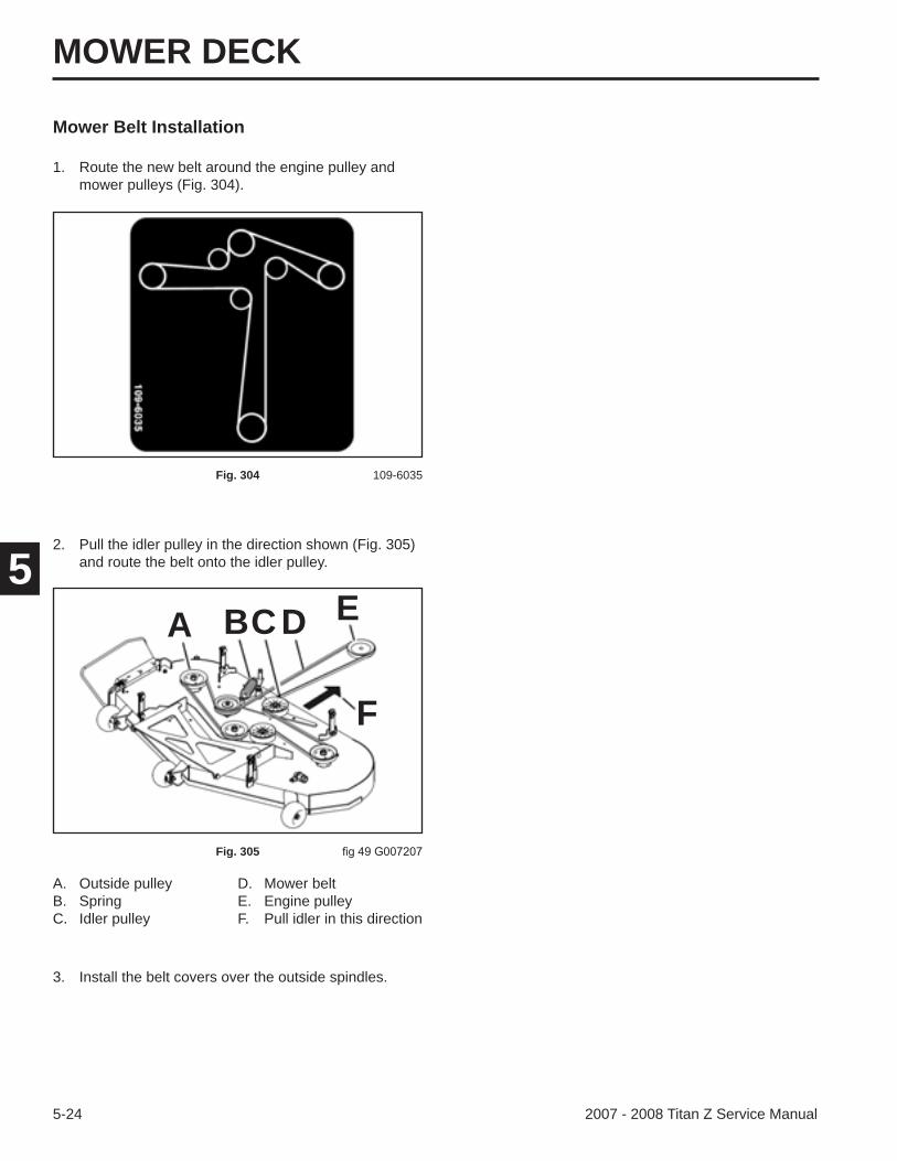
MOWER DECK
5-24 2007 - 2008 Titan Z Service Manual
5
Mower Belt Installation
1. Route the new belt around the engine pulley and mower pulleys (Fig. 304).
Fig. 304 109-6035
A. Outside pulley D. Mower beltB. Spring E. Engine pulleyC. Idler pulley F. Pull idler in this direction
Fig. 305
2. Pull the idler pulley in the direction shown (Fig. 305)and route the belt onto the idler pulley.
A BCD E
F
3. Install the belt covers over the outside spindles.
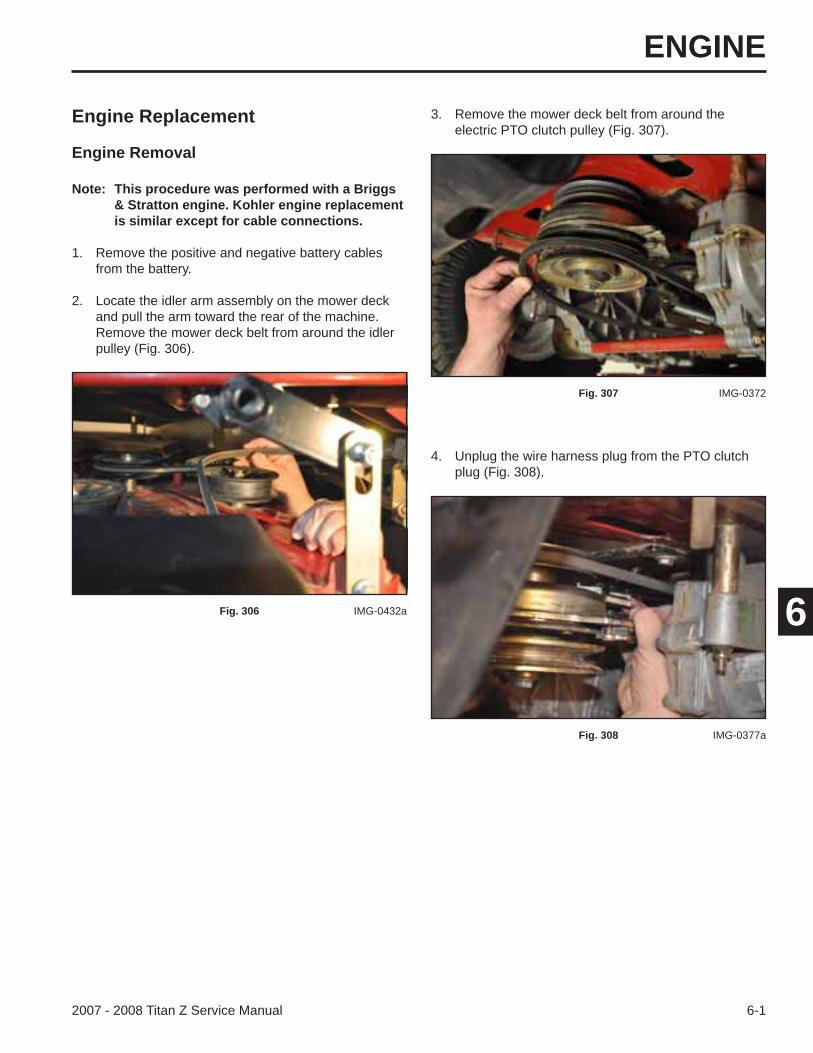
ENGINE
6-12007 - 2008 Titan Z Service Manual
6
Engine Replacement
Engine Removal
Note: This procedure was performed with a Briggs & Stratton engine. Kohler engine replacement is similar except for cable connections.
1. Remove the positive and negative battery cables from the battery.
2. Locate the idler arm assembly on the mower deck and pull the arm toward the rear of the machine. Remove the mower deck belt from around the idler pulley (Fig. 306).
Fig. 306 IMG-0432a
3. Remove the mower deck belt from around the electric PTO clutch pulley (Fig. 307).
Fig. 307 IMG-0372
4. Unplug the wire harness plug from the PTO clutch plug (Fig. 308).
Fig. 308 IMG-0377a
ENGINE
6-2 2007 - 2008 Titan Z Service Manual
6
6. Remove the electric PTO clutch from the engine crankshaft (Fig. 310).
Fig. 310 IMG-0379
7. Using a spring tool (Toro part number 92-5771), rotate the transmission drive belt idler arm to release tension from the transmission drive belt. Remove the transmission drive belt from the idler pulley (Fig. 311).
Fig. 311 IMG-0423a
8. Remove the transmission drive belt from the engine pulley (Fig. 312).
Fig. 312 IMG-0419
5. Remove the clutch bolt securing the electric PTO clutch to the engine crankshaft (Fig. 309).
Fig. 309 IMG-0378
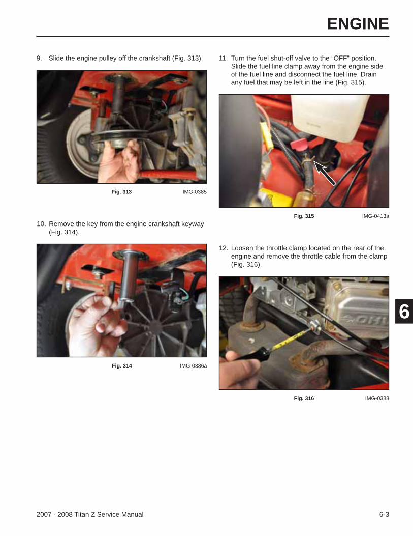
ENGINE
6-32007 - 2008 Titan Z Service Manual
6
10. Remove the key from the engine crankshaft keyway (Fig. 314).
Fig. 314 IMG-0386a
12. Loosen the throttle clamp located on the rear of the engine and remove the throttle cable from the clamp (Fig. 316).
Fig. 316 IMG-0388
9. Slide the engine pulley off the crankshaft (Fig. 313).
Fig. 313 IMG-0385
11. Turn the fuel shut-off valve to the “OFF” position. Slide the fuel line clamp away from the engine side of the fuel line and disconnect the fuel line. Drain any fuel that may be left in the line (Fig. 315).
Fig. 315 IMG-0413a
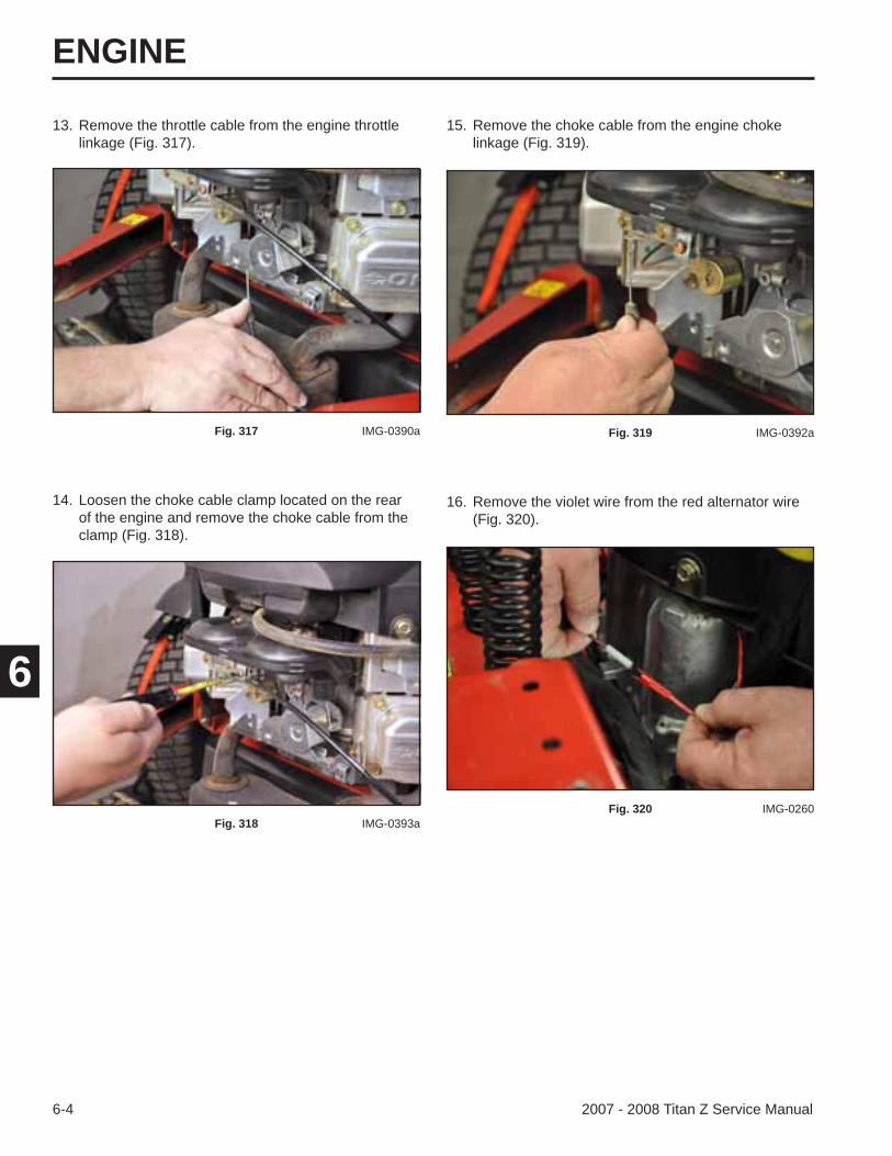
ENGINE
6-4 2007 - 2008 Titan Z Service Manual
6
14. Loosen the choke cable clamp located on the rear of the engine and remove the choke cable from the clamp (Fig. 318).
Fig. 318 IMG-0393a
15. Remove the choke cable from the engine choke linkage (Fig. 319).
Fig. 319 IMG-0392a
16. Remove the violet wire from the red alternator wire (Fig. 320).
Fig. 320 IMG-0260
13. Remove the throttle cable from the engine throttle linkage (Fig. 317).
Fig. 317 IMG-0390a
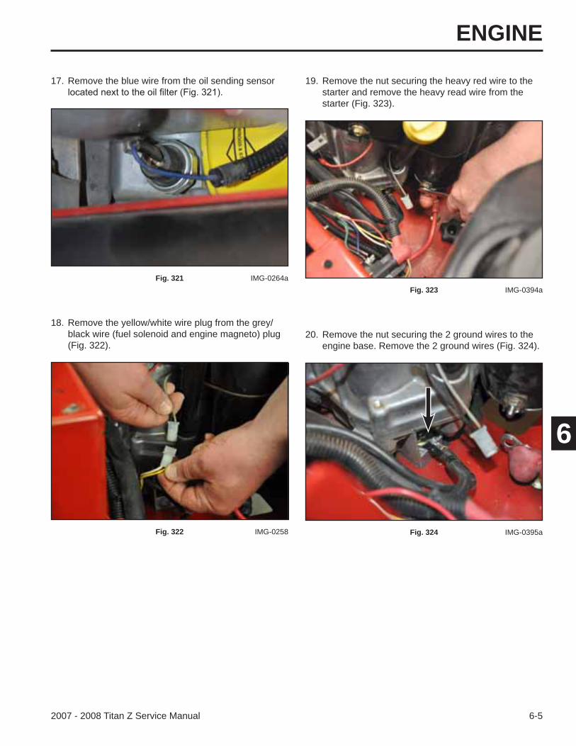
ENGINE
6-52007 - 2008 Titan Z Service Manual
6
18. Remove the yellow/white wire plug from the grey/black wire (fuel solenoid and engine magneto) plug (Fig. 322).
Fig. 322 IMG-0258
19. Remove the nut securing the heavy red wire to the starter and remove the heavy read wire from the starter (Fig. 323).
Fig. 323 IMG-0394a
17. Remove the blue wire from the oil sending sensor
Fig. 321 IMG-0264a
20. Remove the nut securing the 2 ground wires to the engine base. Remove the 2 ground wires (Fig. 324).
Fig. 324 IMG-0395a
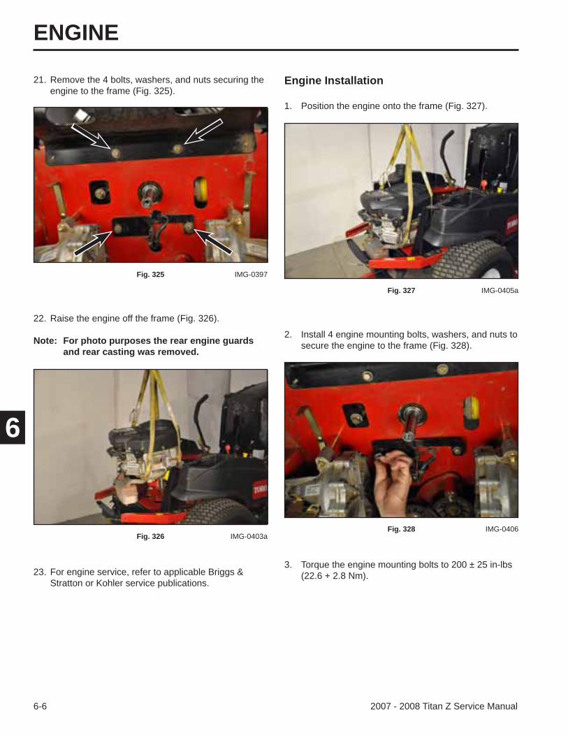
ENGINE
6-6 2007 - 2008 Titan Z Service Manual
6
Engine Installation
2. Install 4 engine mounting bolts, washers, and nuts to secure the engine to the frame (Fig. 328).
1. Position the engine onto the frame (Fig. 327).
Fig. 327 IMG-0405a
Fig. 328 IMG-0406
22. Raise the engine off the frame (Fig. 326).
Note: For photo purposes the rear engine guards and rear casting was removed.
Fig. 326 IMG-0403a
23. For engine service, refer to applicable Briggs & Stratton or Kohler service publications.
3. Torque the engine mounting bolts to 200 ± 25 in-lbs (22.6 + 2.8 Nm).
21. Remove the 4 bolts, washers, and nuts securing the engine to the frame (Fig. 325).
Fig. 325 IMG-0397
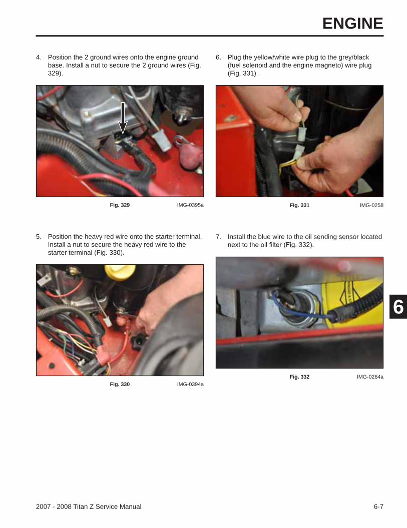
ENGINE
6-72007 - 2008 Titan Z Service Manual
6
7. Install the blue wire to the oil sending sensor located
4. Position the 2 ground wires onto the engine ground base. Install a nut to secure the 2 ground wires (Fig. 329).
6. Plug the yellow/white wire plug to the grey/black (fuel solenoid and the engine magneto) wire plug (Fig. 331).
Fig. 329 IMG-0395a
5. Position the heavy red wire onto the starter terminal. Install a nut to secure the heavy red wire to the starter terminal (Fig. 330).
Fig. 330 IMG-0394a
Fig. 331 IMG-0258
Fig. 332 IMG-0264a
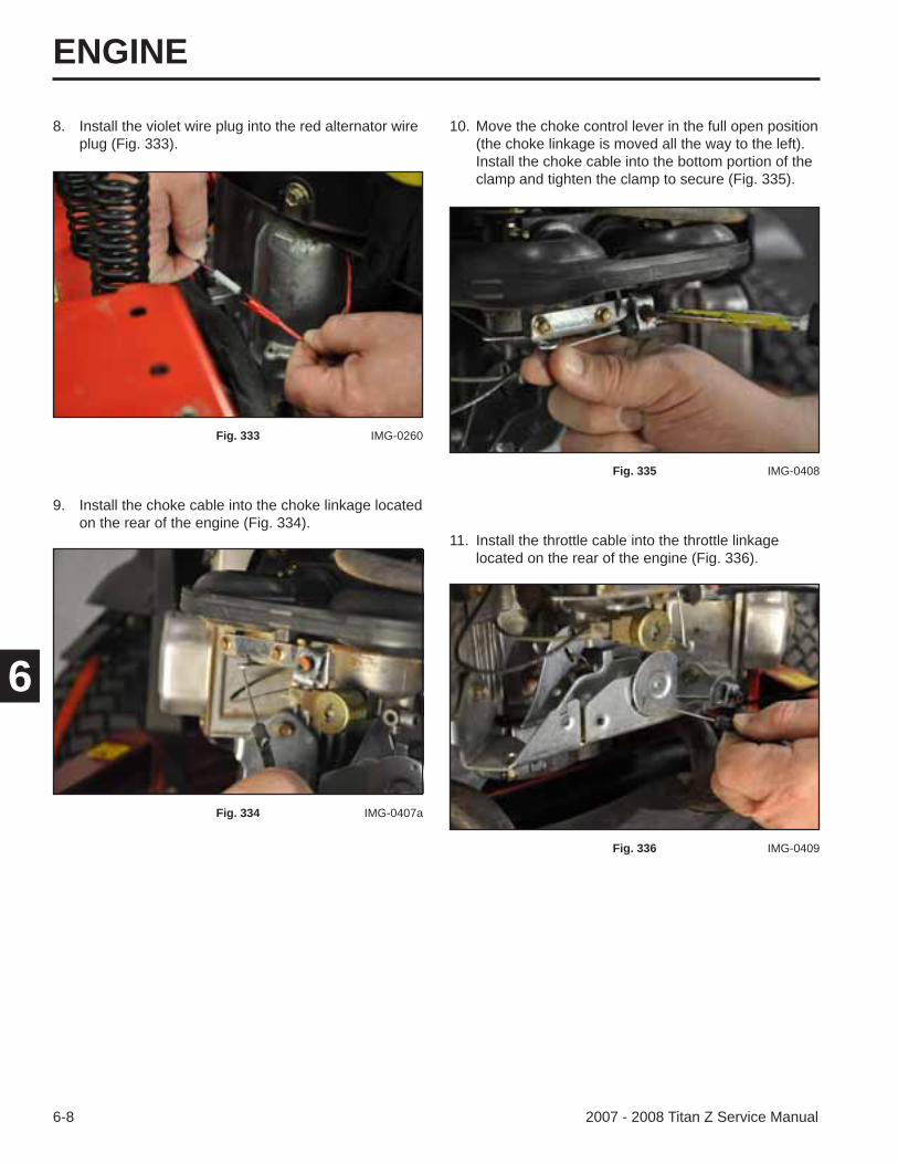
ENGINE
6-8 2007 - 2008 Titan Z Service Manual
6
8. Install the violet wire plug into the red alternator wire plug (Fig. 333).
9. Install the choke cable into the choke linkage located on the rear of the engine (Fig. 334).
11. Install the throttle cable into the throttle linkage located on the rear of the engine (Fig. 336).
10. Move the choke control lever in the full open position (the choke linkage is moved all the way to the left). Install the choke cable into the bottom portion of the clamp and tighten the clamp to secure (Fig. 335).
Fig. 333 IMG-0260
Fig. 334 IMG-0407a
Fig. 335 IMG-0408
Fig. 336 IMG-0409
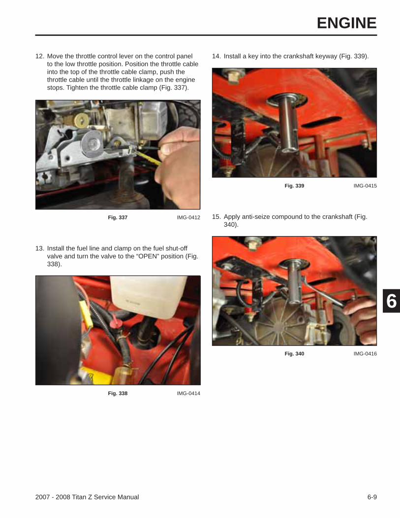
ENGINE
6-92007 - 2008 Titan Z Service Manual
6
13. Install the fuel line and clamp on the fuel shut-off valve and turn the valve to the “OPEN” position (Fig. 338).
12. Move the throttle control lever on the control panel to the low throttle position. Position the throttle cable into the top of the throttle cable clamp, push the throttle cable until the throttle linkage on the engine stops. Tighten the throttle cable clamp (Fig. 337).
14. Install a key into the crankshaft keyway (Fig. 339).
Fig. 337 IMG-0412
Fig. 338 IMG-0414
Fig. 339 IMG-0415
15. Apply anti-seize compound to the crankshaft (Fig. 340).
Fig. 340 IMG-0416
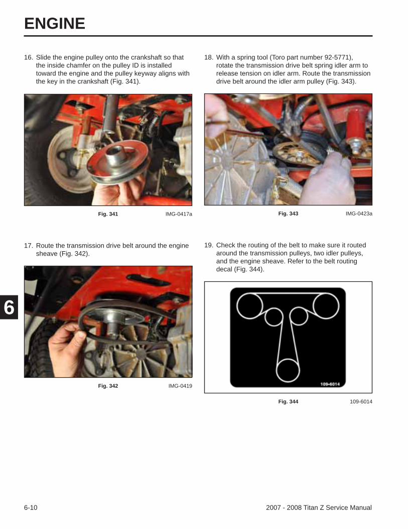
ENGINE
6-10 2007 - 2008 Titan Z Service Manual
6
16. Slide the engine pulley onto the crankshaft so that the inside chamfer on the pulley ID is installed toward the engine and the pulley keyway aligns with the key in the crankshaft (Fig. 341).
18. With a spring tool (Toro part number 92-5771), rotate the transmission drive belt spring idler arm to release tension on idler arm. Route the transmission drive belt around the idler arm pulley (Fig. 343).
Fig. 341 IMG-0417a
17. Route the transmission drive belt around the engine sheave (Fig. 342).
Fig. 342 IMG-0419
Fig. 343 IMG-0423a
19. Check the routing of the belt to make sure it routed around the transmission pulleys, two idler pulleys, and the engine sheave. Refer to the belt routing decal (Fig. 344).
Fig. 344 109-6014
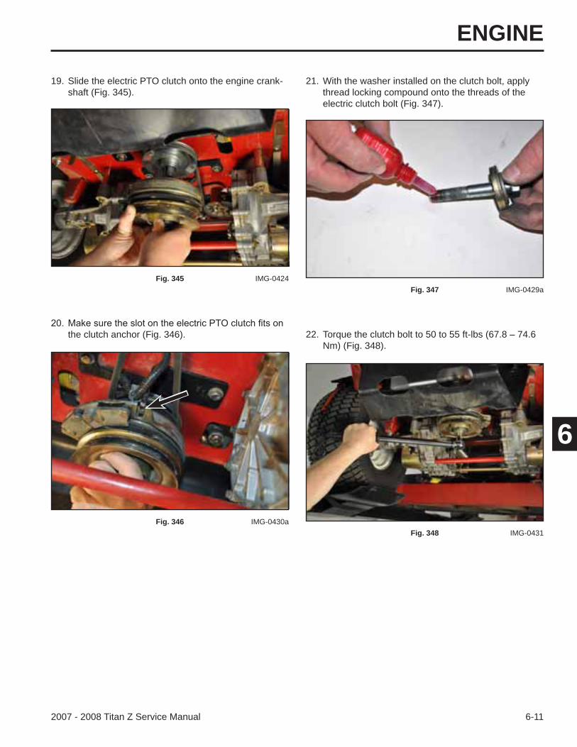
ENGINE
6-112007 - 2008 Titan Z Service Manual
6
21. With the washer installed on the clutch bolt, apply thread locking compound onto the threads of the electric clutch bolt (Fig. 347).
the clutch anchor (Fig. 346).
Fig. 346 IMG-0430a
Fig. 347 IMG-0429a
22. Torque the clutch bolt to 50 to 55 ft-lbs (67.8 – 74.6 Nm) (Fig. 348).
Fig. 348 IMG-0431
19. Slide the electric PTO clutch onto the engine crank-shaft (Fig. 345).
Fig. 345 IMG-0424

ENGINE
6-12 2007 - 2008 Titan Z Service Manual
6
25. Pull the mower deck idler arm assembly toward the rear of the machine and route the mower belt around the idler pulley (Fig. 351).
24. Route the mower deck belt around the electric PTO clutch (Fig. 350).
Fig. 350 IMG-0372
Fig. 351 IMG-0432a
27. Install the positive and then the negative battery cable to the battery.
23. Plug the wire harness connector to the electric PTO clutch connector (Fig. 349).
Fig. 349 IMG-0377a
26. Check the mower deck belt routing (Fig. 352).
Fig. 352 109-6035
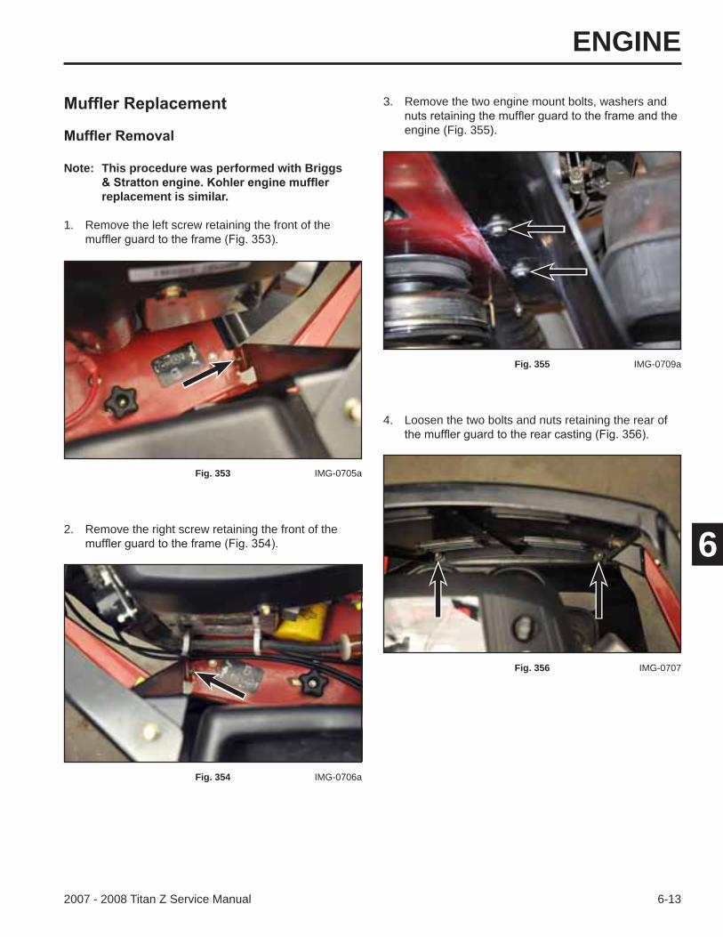
ENGINE
6-132007 - 2008 Titan Z Service Manual
6
4. Loosen the two bolts and nuts retaining the rear of
3. Remove the two engine mount bolts, washers and
engine (Fig. 355).
Fig. 355 IMG-0709a
Fig. 356 IMG-0707
Note: This procedure was performed with Briggs
replacement is similar.
1. Remove the left screw retaining the front of the
Fig. 353 IMG-0705a
2. Remove the right screw retaining the front of the
Fig. 354 IMG-0706a
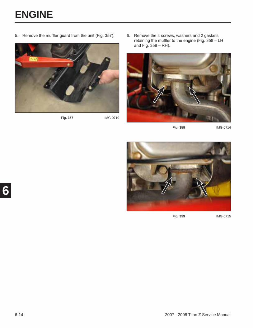
ENGINE
6-14 2007 - 2008 Titan Z Service Manual
6
6. Remove the 4 screws, washers and 2 gaskets
Fig. 358 IMG-0714
Fig. 359 IMG-0715
Fig. 357 IMG-0710
ENGINE
6-152007 - 2008 Titan Z Service Manual
6Torque the engine mounting bolts to 200 ±
Fig. 360 IMG-0717

ENGINE
6-16 2007 - 2008 Titan Z Service Manual
6
THIS PAGE INTENTIONALLY LEFT BLANK.
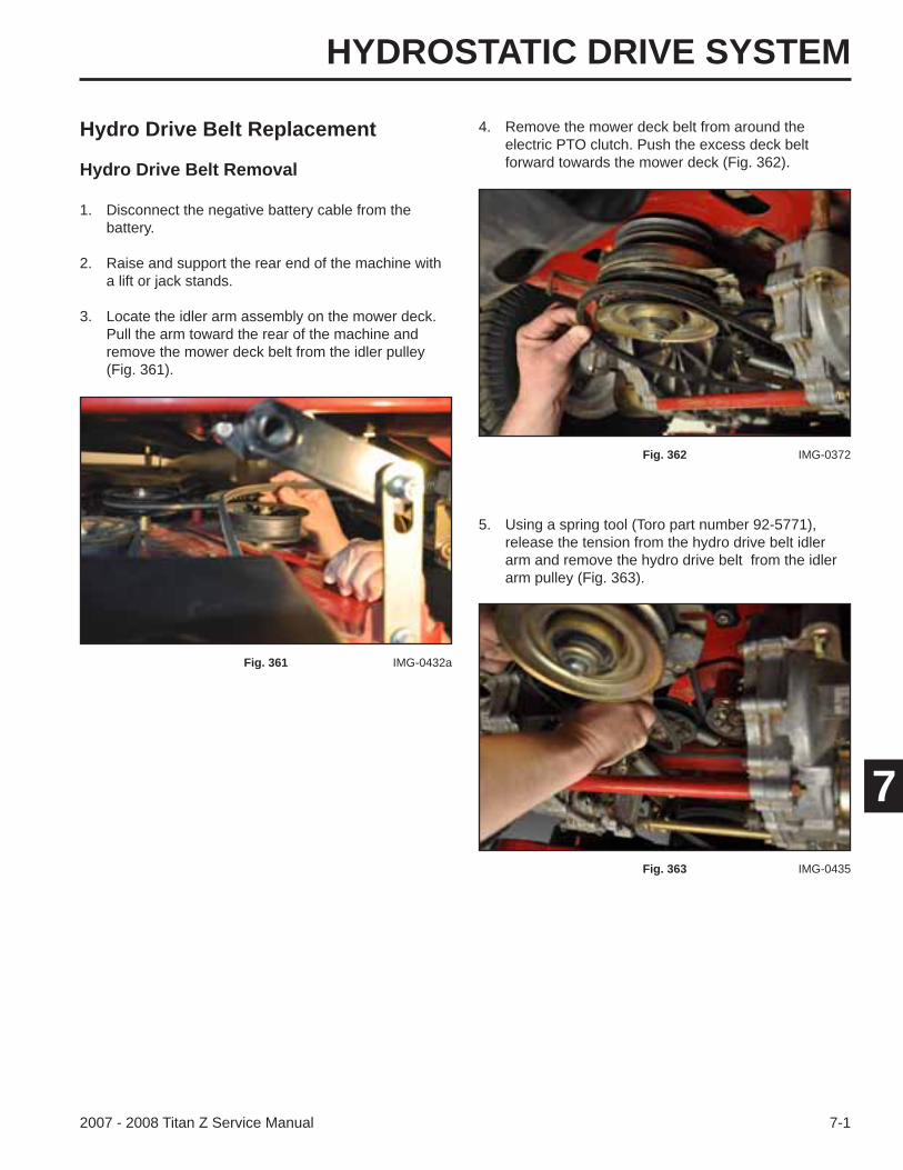
HYDROSTATIC DRIVE SYSTEM
7-12007 - 2008 Titan Z Service Manual
7
Hydro Drive Belt Replacement
Hydro Drive Belt Removal
1. Disconnect the negative battery cable from the battery.
2. Raise and support the rear end of the machine with a lift or jack stands.
3. Locate the idler arm assembly on the mower deck. Pull the arm toward the rear of the machine and remove the mower deck belt from the idler pulley (Fig. 361).
4. Remove the mower deck belt from around the electric PTO clutch. Push the excess deck belt forward towards the mower deck (Fig. 362).
Fig. 361 IMG-0432a
Fig. 362 IMG-0372
5. Using a spring tool (Toro part number 92-5771), release the tension from the hydro drive belt idler arm and remove the hydro drive belt from the idler arm pulley (Fig. 363).
Fig. 363 IMG-0435
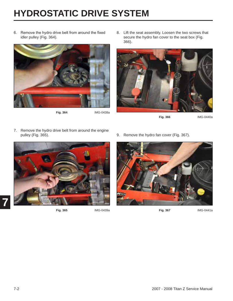
HYDROSTATIC DRIVE SYSTEM
7-2 2007 - 2008 Titan Z Service Manual
7
idler pulley (Fig. 364).
7. Remove the hydro drive belt from around the engine pulley (Fig. 365). 9. Remove the hydro fan cover (Fig. 367).
8. Lift the seat assembly. Loosen the two screws that secure the hydro fan cover to the seat box (Fig. 366).
Fig. 364 IMG-0438a
Fig. 365 IMG-0439a
Fig. 366 IMG-0440a
Fig. 367 IMG-0441a
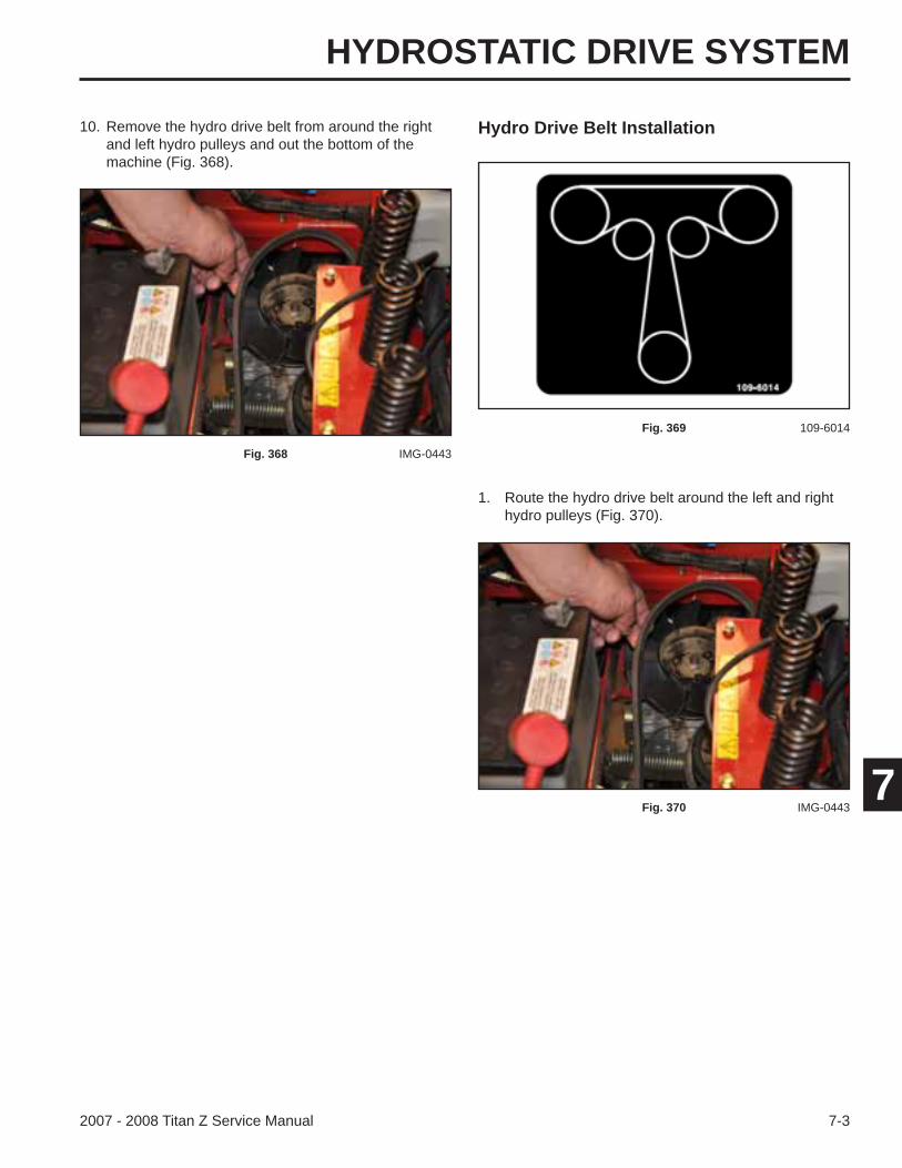
HYDROSTATIC DRIVE SYSTEM
7-32007 - 2008 Titan Z Service Manual
7
Hydro Drive Belt Installation
1. Route the hydro drive belt around the left and right hydro pulleys (Fig. 370).
10. Remove the hydro drive belt from around the right and left hydro pulleys and out the bottom of the machine (Fig. 368).
Fig. 368 IMG-0443
Fig. 369 109-6014
Fig. 370 IMG-0443
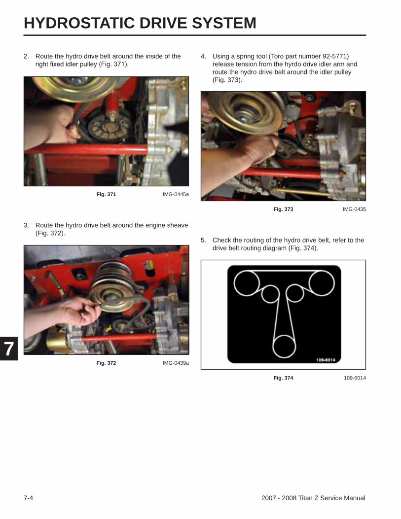
HYDROSTATIC DRIVE SYSTEM
7-4 2007 - 2008 Titan Z Service Manual
7
2. Route the hydro drive belt around the inside of the
3. Route the hydro drive belt around the engine sheave (Fig. 372).
4. Using a spring tool (Toro part number 92-5771) release tension from the hyrdo drive idler arm and route the hydro drive belt around the idler pulley (Fig. 373).
Fig. 371 IMG-0445a
Fig. 372 IMG-0439a
Fig. 373 IMG-0435
5. Check the routing of the hydro drive belt, refer to the drive belt routing diagram (Fig. 374).
Fig. 374 109-6014
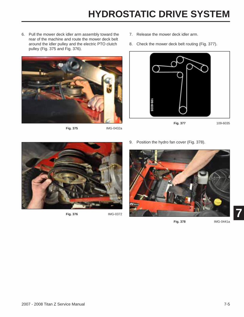
HYDROSTATIC DRIVE SYSTEM
7-52007 - 2008 Titan Z Service Manual
7
6. Pull the mower deck idler arm assembly toward the rear of the machine and route the mower deck belt around the idler pulley and the electric PTO clutch pulley (Fig. 375 and Fig. 376).
Fig. 375 IMG-0432a
Fig. 376 IMG-0372
9. Position the hydro fan cover (Fig. 378).
Fig. 378 IMG-0441a
7. Release the mower deck idler arm.
8. Check the mower deck belt routing (Fig. 377).
Fig. 377 109-6035
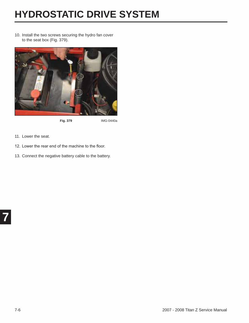
HYDROSTATIC DRIVE SYSTEM
7-6 2007 - 2008 Titan Z Service Manual
7
10. Install the two screws securing the hydro fan cover to the seat box (Fig. 379).
Fig. 379 IMG-0440a
11. Lower the seat.
13. Connect the negative battery cable to the battery.
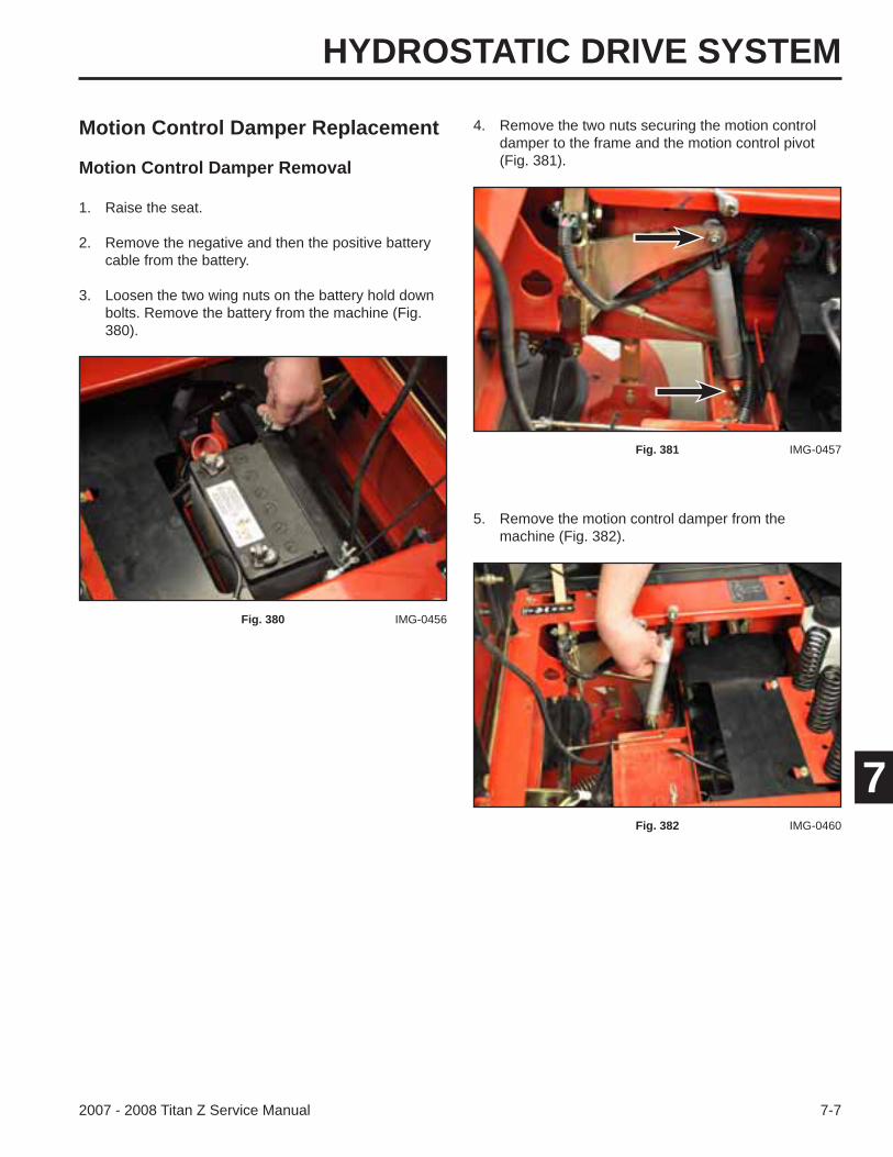
HYDROSTATIC DRIVE SYSTEM
7-72007 - 2008 Titan Z Service Manual
7
Motion Control Damper Replacement
Motion Control Damper Removal
1. Raise the seat.
2. Remove the negative and then the positive battery cable from the battery.
3. Loosen the two wing nuts on the battery hold down bolts. Remove the battery from the machine (Fig. 380).
5. Remove the motion control damper from the machine (Fig. 382).
4. Remove the two nuts securing the motion control damper to the frame and the motion control pivot (Fig. 381).
Fig. 380 IMG-0456
Fig. 381 IMG-0457
Fig. 382 IMG-0460
HYDROSTATIC DRIVE SYSTEM
7-8 2007 - 2008 Titan Z Service Manual
7
Motion Control Damper Installation
1. Install two nuts on each screw of the motion control damper (Fig. 383).
3. Install a nut on each end of the damper to secure (Fig. 385).
Fig. 383 IMG-0468a
Install the rod end of the damper to the motion control pivot (Fig. 384).
Fig. 384 IMG-0476
Fig. 385 IMG-0477
4. Position the battery into the machine. Install the battery hold down to secure (Fig. 386).
Fig. 386 IMG-0456
5. Install the positive and then the negative battery cable to the battery.
6. Lower the seat.
HYDROSTATIC DRIVE SYSTEM
7-92007 - 2008 Titan Z Service Manual
7
Motion Control Pivot Assembly Replacement
The following procedures show replacing and servicing the left hand motion control pivot assembly. The same procedures can be followed to replace and service the right hand motion control pivot assembly. Exceptions are noted within the procedures.
6. Unplug the left neutral switch from the harness (Fig. 389).
5. Remove the two screws and washers retaining the left hand lever grip assembly from the lever mount post (Fig. 388).
Motion Control Pivot Removal
1. Raise the seat.
2. Remove the negative and then the positive battery cable from the battery.
3. Loosen the two wing nuts on the battery hold down bolts and remove the battery from the unit (Fig. 387).
4. Left Hand Motion Control Pivot: Remove the left hand fender and fuel tank. Refer to “Left Hand Fender and Fuel Tank Removal” on page 3-7.
Right hand Motion Control Pivot: Remove the right hand fender. Refer to “Right Hand Fender Removal” on page 3-14.
Fig. 387 IMG-0456
Fig. 388 IMG-0523a
Fig. 389 IMG-0522a
HYDROSTATIC DRIVE SYSTEM
7-10 2007 - 2008 Titan Z Service Manual
7
8. Remove the bolt and nut securing the steering rod to the left hand motion control pivot assembly (Fig. 391).
10. Remove the control pivot pin from the motion control pivot assembly (Fig. 393).
7. Remove the nut from the top of the left hand motion control damper and move the damper out of the motion control pivot (Fig. 390).
9. Remove the cotter pin located on the control pivot pin (Fig. 392).
Fig. 390 IMG-0480
Fig. 391 IMG-0482a
Fig. 392 IMG-0483a
Fig. 393 IMG-0484a
HYDROSTATIC DRIVE SYSTEM
7-112007 - 2008 Titan Z Service Manual
7
11. Remove the motion control pivot assembly from the seat box assembly (Fig. 394).
Fig. 394 IMG-0485

HYDROSTATIC DRIVE SYSTEM
7-12 2007 - 2008 Titan Z Service Manual
7
Motion Control Pivot Disassembly 3. With a long punch and hammer, remove the two bearings in the motion control pivot (Fig. 397).
Fig. 397 IMG-0494a
2. Remove the two bolts, metal washers, (2) plastic washers, and nuts retaining the lever mount post to the motion control pivot (Fig. 396).
1. Remove the neutral switch from the motion control pivot assembly (Fig. 395).
Fig. 395 IMG-0516a
Fig. 396 IMG-0489a
HYDROSTATIC DRIVE SYSTEM
7-132007 - 2008 Titan Z Service Manual
7
Motion Control Pivot Assembly
2. Install the bolts, metal washers, plastic washers, lever mount post, and nuts to the motion control pivot (Fig. 399).
1. Tap two new bearings into the motion control pivot assembly (Fig. 398).
Fig. 398 IMG-0502a
Fig. 399 IMG-0506a
A. Nuts D. Motion Control PivotB. Lever Mount Post E. Metal WashersC. Plastic Washers (4) F. Bolts
A
BC C
D
E F
3. Tighten the bolts and nuts until you feel resistance on the lever mount post - Do Not over-tighten (Fig. 400).
4. Install the neutral switch into the motion control pivot assembly (Fig. 401).
Fig. 400 IMG-0489a
Fig. 401 IMG-0516a
HYDROSTATIC DRIVE SYSTEM
7-14 2007 - 2008 Titan Z Service Manual
7
Motion Control Pivot Assembly Installation
4. Install a bolt and nut securing the steering rod to the left hand motion control pivot assembly (Fig. 405).
3. Install a cotter pin on the end of the control pivot pin (Fig. 404).
Fig. 404 IMG-0521
Fig. 405 IMG-0482a
1. Install the left hand motion control pivot assembly between the seat box assembly and the motion control bracket (Fig. 402).
Fig. 402 IMG-0519
2. Install the control pivot pin from the outside of the seat box assembly through the left hand motion control pivot assembly into the motion control bracket (Fig. 403).
Fig. 403 IMG-0484a
HYDROSTATIC DRIVE SYSTEM
7-152007 - 2008 Titan Z Service Manual
7
6. Plug the wire harness plug onto the left neutral switch (Fig. 407).
5. Install the motion control damper screw through the left hand motion control pivot assembly. Install a nut to secure (Fig. 406).
Fig. 406 IMG-0480a
Fig. 407 IMG-0522a
7. Install two screws and washers retaining the left hand lever grip assembly to the lever mount post (Fig. 408).
Fig. 408 IMG-0523a
8. Left Hand Motion Control Pivot: Install the left hand fender and fuel tank. Refer to “Left Hand Fender and Fuel Tank Installation” on page 3-10
Right Hand Motion Control Pivot: Install the right hand fender. Refer to “Right Hand Fender Install-ation” on page 3-17.
HYDROSTATIC DRIVE SYSTEM
7-16 2007 - 2008 Titan Z Service Manual
7
Brake Linkage & Brake Handle Assembly Replacement
Brake Linkage & Brake Handle Assembly Removal
1. Raise the seat.
2. Remove the negative and then the positive battery cable from the battery.
3. Loosen the two wing nuts on the battery hold down bolts and remove the battery from the machine (Fig. 410).
Fig. 410 IMG-0456
10. Install the positive and then the negative battery cable to the battery.
11. Start the machine and allow it warm up. Check the forward, reverse and neutral operation. If the machine needs neutral adjustment, refer to “Neutral Adjustment” on page 7-39.
9. Position the battery into the machine. Install the battery hold down bracket to secure (Fig. 409).
Fig. 409 IMG-0456
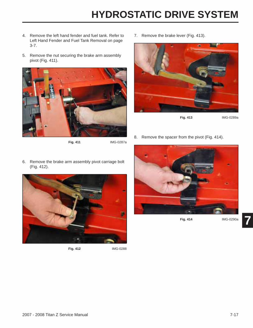
HYDROSTATIC DRIVE SYSTEM
7-172007 - 2008 Titan Z Service Manual
7
4. Remove the left hand fender and fuel tank. Refer to Left Hand Fender and Fuel Tank Removal on page 3-7.
5. Remove the nut securing the brake arm assembly pivot (Fig. 411).
Fig. 411 IMG-0287a
6. Remove the brake arm assembly pivot carriage bolt (Fig. 412).
Fig. 412 IMG-0288
7. Remove the brake lever (Fig. 413).
Fig. 413 IMG-0289a
8. Remove the spacer from the pivot (Fig. 414).
Fig. 414 IMG-0290a

HYDROSTATIC DRIVE SYSTEM
7-18 2007 - 2008 Titan Z Service Manual
7
12. Remove the brake pivot tube (Fig. 418).
11. Remove the spacer from the inside end of the brake pivot tube (Fig. 417).
Fig. 417 IMG-0293a
Fig. 418 IMG-0294a
10. Remove the washer located on the inside end of the brake pivot tube (Fig. 416).
9. Pull the brake pivot tube assembly out slightly from the frame (Fig. 415).
Fig. 415 IMG-0291a
Fig. 416 IMG-0292a
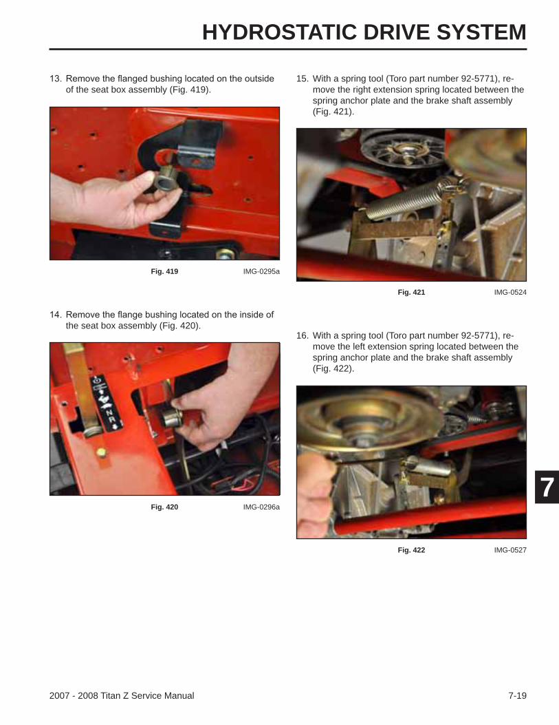
HYDROSTATIC DRIVE SYSTEM
7-192007 - 2008 Titan Z Service Manual
7
the seat box assembly (Fig. 420).
of the seat box assembly (Fig. 419).
Fig. 419 IMG-0295a
Fig. 420 IMG-0296a
15. With a spring tool (Toro part number 92-5771), re-move the right extension spring located between the spring anchor plate and the brake shaft assembly (Fig. 421).
Fig. 421 IMG-0524
16. With a spring tool (Toro part number 92-5771), re-move the left extension spring located between the spring anchor plate and the brake shaft assembly (Fig. 422).
Fig. 422 IMG-0527
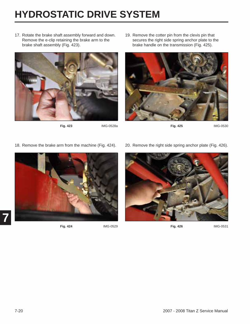
HYDROSTATIC DRIVE SYSTEM
7-20 2007 - 2008 Titan Z Service Manual
7
20. Remove the right side spring anchor plate (Fig. 426).
19. Remove the cotter pin from the clevis pin that secures the right side spring anchor plate to the brake handle on the transmission (Fig. 425).
Fig. 425 IMG-0530
Fig. 426 IMG-0531
18. Remove the brake arm from the machine (Fig. 424).
17. Rotate the brake shaft assembly forward and down. Remove the e-clip retaining the brake arm to the brake shaft assembly (Fig. 423).
Fig. 423 IMG-0528a
Fig. 424 IMG-0529
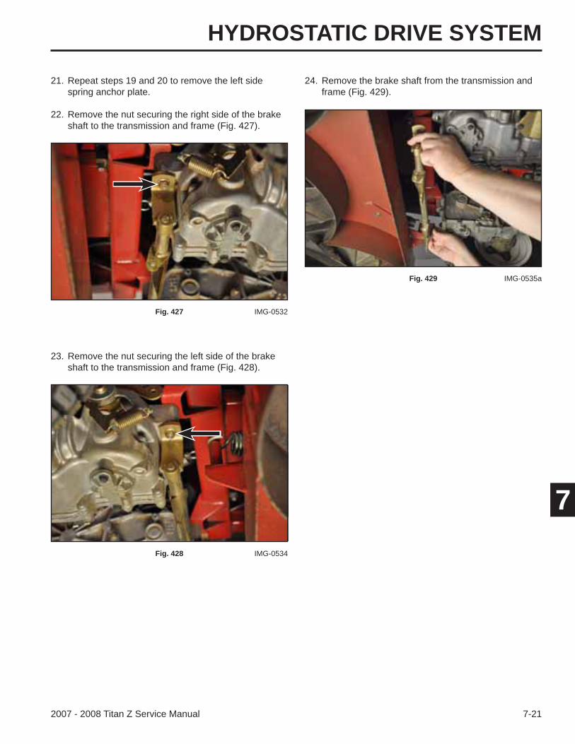
HYDROSTATIC DRIVE SYSTEM
7-212007 - 2008 Titan Z Service Manual
7
23. Remove the nut securing the left side of the brake shaft to the transmission and frame (Fig. 428).
21. Repeat steps 19 and 20 to remove the left side spring anchor plate.
22. Remove the nut securing the right side of the brake shaft to the transmission and frame (Fig. 427).
Fig. 427 IMG-0532
Fig. 428 IMG-0534
24. Remove the brake shaft from the transmission and frame (Fig. 429).
Fig. 429 IMG-0535a
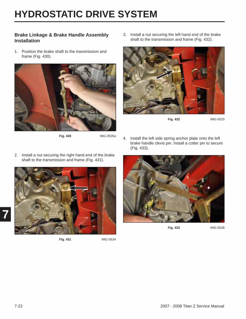
HYDROSTATIC DRIVE SYSTEM
7-22 2007 - 2008 Titan Z Service Manual
7
Brake Linkage & Brake Handle Assembly Installation
3. Install a nut securing the left hand end of the brake shaft to the transmission and frame (Fig. 432).
Fig. 432 IMG-0533
4. Install the left side spring anchor plate onto the left brake handle clevis pin. Install a cotter pin to secure (Fig. 433).
Fig. 433 IMG-0538
1. Position the brake shaft to the transmission and frame (Fig. 430).
Fig. 430 IMG-0535a
2. Install a nut securing the right hand end of the brake shaft to the transmission and frame (Fig. 431).
Fig. 431 IMG-0534
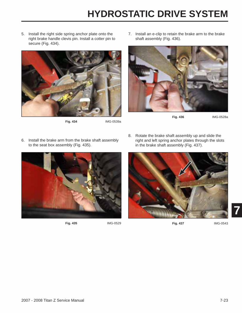
HYDROSTATIC DRIVE SYSTEM
7-232007 - 2008 Titan Z Service Manual
7
5. Install the right side spring anchor plate onto the right brake handle clevis pin. Install a cotter pin to secure (Fig. 434).
7. Install an e-clip to retain the brake arm to the brake shaft assembly (Fig. 436).
Fig. 434 IMG-0539a
6. Install the brake arm from the brake shaft assembly to the seat box assembly (Fig. 435).
Fig. 435 IMG-0529
Fig. 436 IMG-0528a
8. Rotate the brake shaft assembly up and slide the right and left spring anchor plates through the slots in the brake shaft assembly (Fig. 437).
Fig. 437 IMG-0543
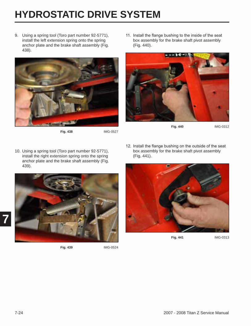
HYDROSTATIC DRIVE SYSTEM
7-24 2007 - 2008 Titan Z Service Manual
7
box assembly for the brake shaft pivot assembly (Fig. 441).
Fig. 441 IMG-0313
9. Using a spring tool (Toro part number 92-5771), install the left extension spring onto the spring anchor plate and the brake shaft assembly (Fig. 438).
box assembly for the brake shaft pivot assembly (Fig. 440).
Fig. 438 IMG-0527
10. Using a spring tool (Toro part number 92-5771), install the right extension spring onto the spring anchor plate and the brake shaft assembly (Fig. 439).
Fig. 439 IMG-0524
Fig. 440 IMG-0312
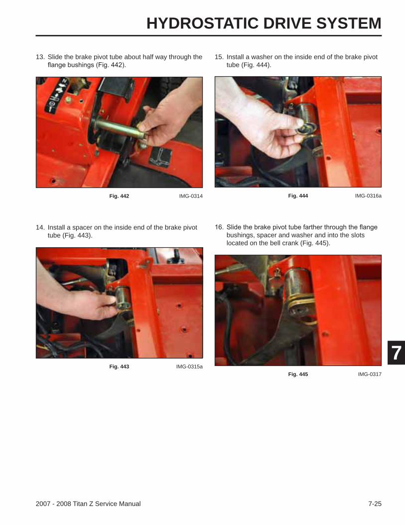
HYDROSTATIC DRIVE SYSTEM
7-252007 - 2008 Titan Z Service Manual
7
13. Slide the brake pivot tube about half way through the 15. Install a washer on the inside end of the brake pivot tube (Fig. 444).
Fig. 442 IMG-0314
14. Install a spacer on the inside end of the brake pivot tube (Fig. 443).
Fig. 443 IMG-0315a
Fig. 444 IMG-0316a
bushings, spacer and washer and into the slots located on the bell crank (Fig. 445).
Fig. 445 IMG-0317

HYDROSTATIC DRIVE SYSTEM
7-26 2007 - 2008 Titan Z Service Manual
7
20. Install a nut on the end of the carriage bolt to secure (Fig. 449).
Fig. 449 IMG-0323a
17. Install a spacer on the outside end of the brake pivot tube (Fig. 446).
19. Slide a carriage bolt through the brake pivot tube (Fig. 448).
Fig. 446 IMG-0319
18. Install the brake lever assembly on the outside end of the brake pivot tube (Fig. 447).
Fig. 447 IMG-0289a
Fig. 448 IMG-0288
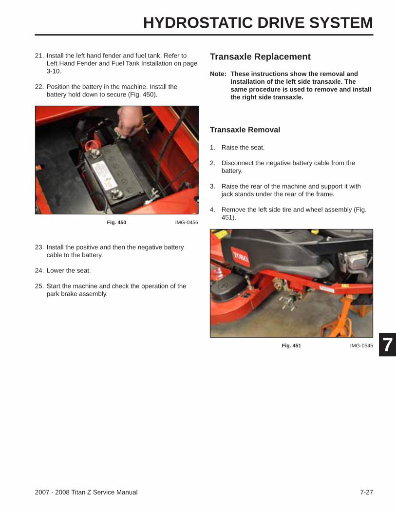
HYDROSTATIC DRIVE SYSTEM
7-272007 - 2008 Titan Z Service Manual
7
23. Install the positive and then the negative battery cable to the battery.
24. Lower the seat.
25. Start the machine and check the operation of the park brake assembly.
21. Install the left hand fender and fuel tank. Refer to Left Hand Fender and Fuel Tank Installation on page 3-10.
22. Position the battery in the machine. Install the battery hold down to secure (Fig. 450).
Fig. 450 IMG-0456
Transaxle Replacement
Transaxle Removal
Note: These instructions show the removal and Installation of the left side transaxle. The same procedure is used to remove and install the right side transaxle.
1. Raise the seat.
2. Disconnect the negative battery cable from the battery.
3. Raise the rear of the machine and support it with jack stands under the rear of the frame.
4. Remove the left side tire and wheel assembly (Fig. 451).
Fig. 451 IMG-0545
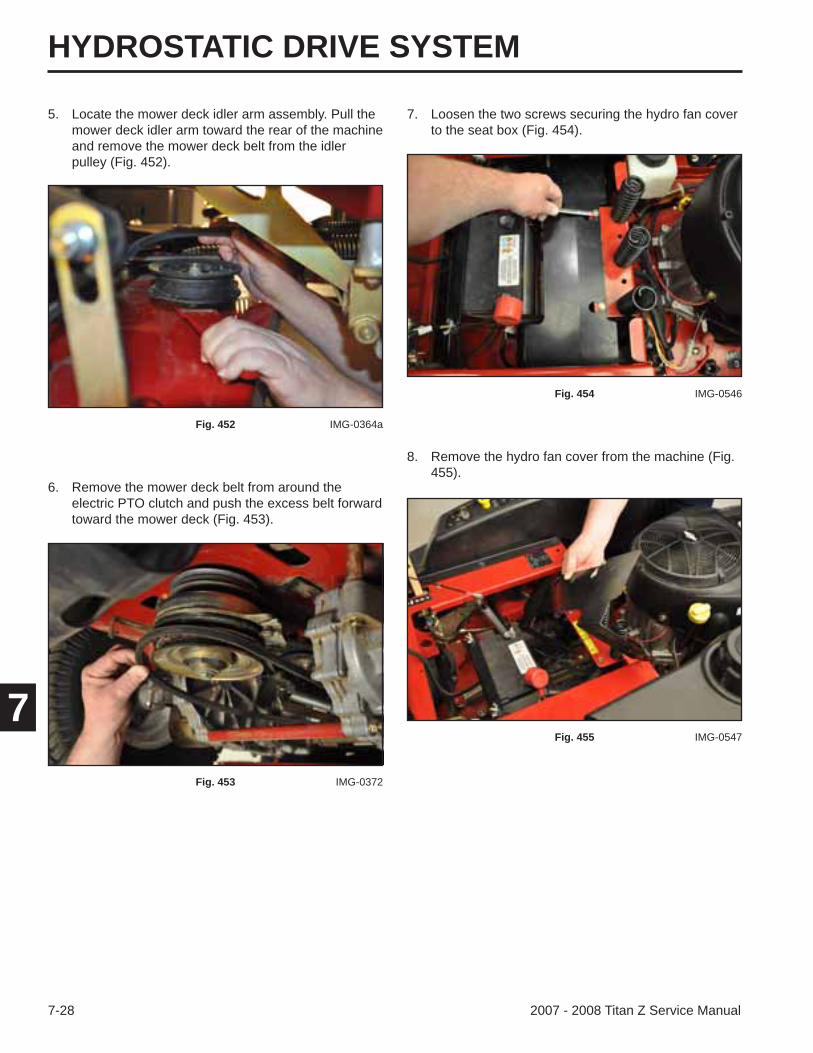
HYDROSTATIC DRIVE SYSTEM
7-28 2007 - 2008 Titan Z Service Manual
7
7. Loosen the two screws securing the hydro fan cover to the seat box (Fig. 454).
Fig. 454 IMG-0546
8. Remove the hydro fan cover from the machine (Fig. 455).
Fig. 455 IMG-0547
6. Remove the mower deck belt from around the electric PTO clutch and push the excess belt forward toward the mower deck (Fig. 453).
5. Locate the mower deck idler arm assembly. Pull the mower deck idler arm toward the rear of the machine and remove the mower deck belt from the idler pulley (Fig. 452).
Fig. 452 IMG-0364a
Fig. 453 IMG-0372
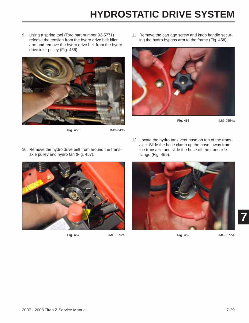
HYDROSTATIC DRIVE SYSTEM
7-292007 - 2008 Titan Z Service Manual
7
10. Remove the hydro drive belt from around the trans-axle pulley and hydro fan (Fig. 457).
9. Using a spring tool (Toro part number 92-5771) release the tension from the hydro drive belt idler arm and remove the hydro drive belt from the hydro drive idler pulley (Fig. 456).
Fig. 456 IMG-0435
Fig. 457 IMG-0552a
11. Remove the carriage screw and knob handle secur-ing the hydro bypass arm to the frame (Fig. 458).
Fig. 458 IMG-0554a
12. Locate the hydro tank vent hose on top of the trans-axle. Slide the hose clamp up the hose, away from the transaxle and slide the hose off the transaxle
Fig. 459 IMG-0555a
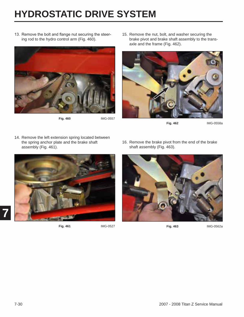
HYDROSTATIC DRIVE SYSTEM
7-30 2007 - 2008 Titan Z Service Manual
7
16. Remove the brake pivot from the end of the brake shaft assembly (Fig. 463).
15. Remove the nut, bolt, and washer securing the brake pivot and brake shaft assembly to the trans-axle and the frame (Fig. 462).
Fig. 462 IMG-0558a
Fig. 463 IMG-0562a
14. Remove the left extension spring located between the spring anchor plate and the brake shaft assembly (Fig. 461).
ing rod to the hydro control arm (Fig. 460).
Fig. 460 IMG-0557
Fig. 461 IMG-0527
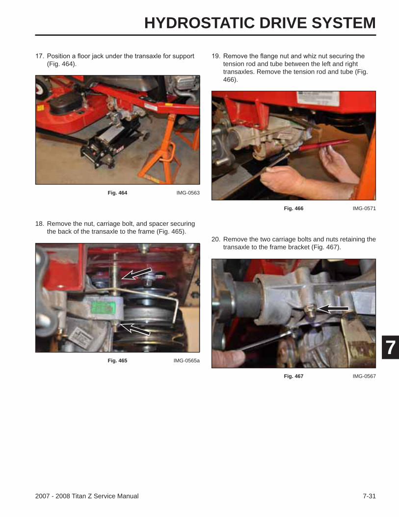
HYDROSTATIC DRIVE SYSTEM
7-312007 - 2008 Titan Z Service Manual
7
18. Remove the nut, carriage bolt, and spacer securing the back of the transaxle to the frame (Fig. 465).
(Fig. 464).
Fig. 464 IMG-0563
Fig. 465 IMG-0565a
tension rod and tube between the left and right transaxles. Remove the tension rod and tube (Fig. 466).
20. Remove the two carriage bolts and nuts retaining the transaxle to the frame bracket (Fig. 467).
Fig. 466 IMG-0571
Fig. 467 IMG-0567
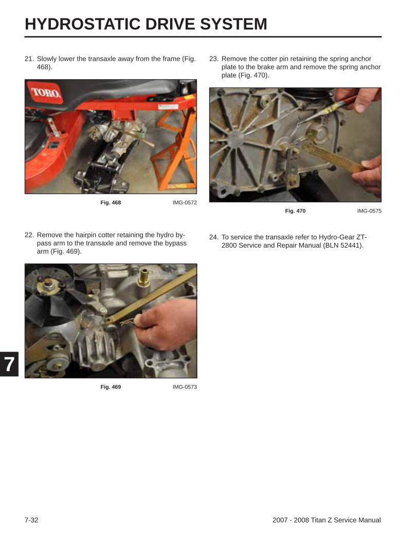
HYDROSTATIC DRIVE SYSTEM
7-32 2007 - 2008 Titan Z Service Manual
7
23. Remove the cotter pin retaining the spring anchor plate to the brake arm and remove the spring anchor plate (Fig. 470).
Fig. 470 IMG-0575
21. Slowly lower the transaxle away from the frame (Fig. 468).
Fig. 468 IMG-0572
22. Remove the hairpin cotter retaining the hydro by-pass arm to the transaxle and remove the bypass arm (Fig. 469).
Fig. 469 IMG-0573
24. To service the transaxle refer to Hydro-Gear ZT-2800 Service and Repair Manual (BLN 52441).
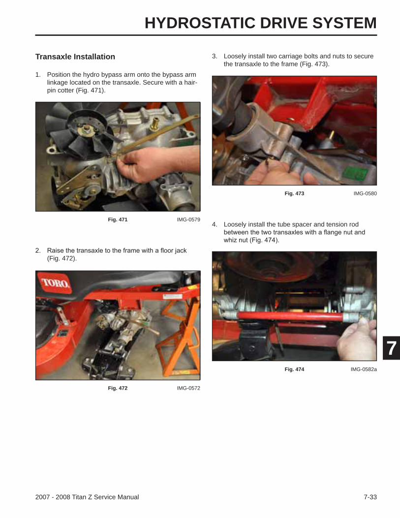
HYDROSTATIC DRIVE SYSTEM
7-332007 - 2008 Titan Z Service Manual
7
Transaxle Installation
(Fig. 472).
1. Position the hydro bypass arm onto the bypass arm linkage located on the transaxle. Secure with a hair-pin cotter (Fig. 471).
Fig. 471 IMG-0579
Fig. 472 IMG-0572
3. Loosely install two carriage bolts and nuts to secure the transaxle to the frame (Fig. 473).
Fig. 473 IMG-0580
4. Loosely install the tube spacer and tension rod
Fig. 474 IMG-0582a
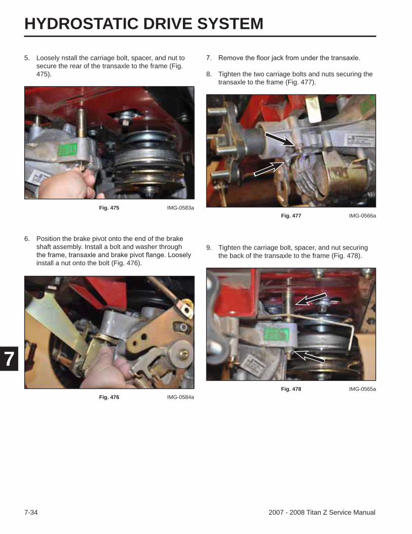
HYDROSTATIC DRIVE SYSTEM
7-34 2007 - 2008 Titan Z Service Manual
7
9. Tighten the carriage bolt, spacer, and nut securing the back of the transaxle to the frame (Fig. 478).
8. Tighten the two carriage bolts and nuts securing the transaxle to the frame (Fig. 477).
Fig. 477 IMG-0566a
Fig. 478 IMG-0565a
5. Loosely nstall the carriage bolt, spacer, and nut to secure the rear of the transaxle to the frame (Fig. 475).
Fig. 475 IMG-0583a
6. Position the brake pivot onto the end of the brake shaft assembly. Install a bolt and washer through
install a nut onto the bolt (Fig. 476).
Fig. 476 IMG-0584a
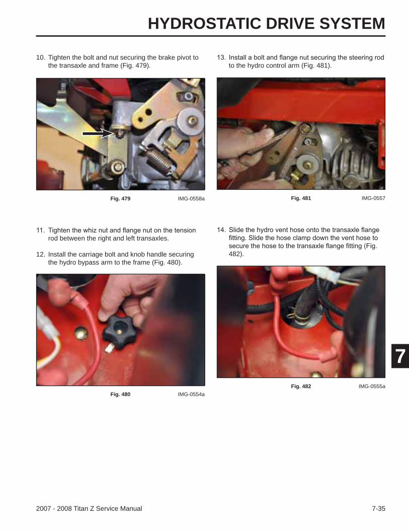
HYDROSTATIC DRIVE SYSTEM
7-352007 - 2008 Titan Z Service Manual
7
10. Tighten the bolt and nut securing the brake pivot to the transaxle and frame (Fig. 479).
Fig. 479 IMG-0558a
rod between the right and left transaxles.
12. Install the carriage bolt and knob handle securing the hydro bypass arm to the frame (Fig. 480).
Fig. 480 IMG-0554a
to the hydro control arm (Fig. 481).
Fig. 481 IMG-0557
482).
Fig. 482 IMG-0555a
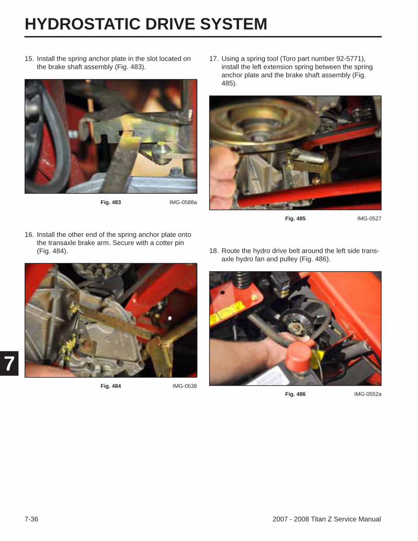
HYDROSTATIC DRIVE SYSTEM
7-36 2007 - 2008 Titan Z Service Manual
7
18. Route the hydro drive belt around the left side trans-axle hydro fan and pulley (Fig. 486).
17. Using a spring tool (Toro part number 92-5771), install the left extension spring between the spring anchor plate and the brake shaft assembly (Fig. 485).
Fig. 485 IMG-0527
Fig. 486 IMG-0552a
15. Install the spring anchor plate in the slot located on the brake shaft assembly (Fig. 483).
Fig. 483 IMG-0588a
16. Install the other end of the spring anchor plate onto the transaxle brake arm. Secure with a cotter pin (Fig. 484).
Fig. 484 IMG-0538

HYDROSTATIC DRIVE SYSTEM
7-372007 - 2008 Titan Z Service Manual
7
21. Check the routing of the hydro drive belt. Refer to the hydro drive belt routing decal (Fig. 489).
19. Route the hydro drive belt around the engine drive pulley (Fig. 487).
20. Using a spring tool (Toro part number 92-5771), release the tension on the hydro drive belt idler arm. Route the belt around the idler pulley (Fig. 488).
Fig. 488 IMG-0435
Fig. 487 IMG-0439a Fig. 489 109-6014
22. Route the mower deck drive belt around the electric PTO clutch pulley (Fig. 490).
Fig. 490 IMG-0372
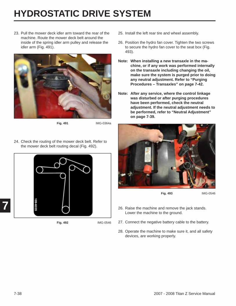
HYDROSTATIC DRIVE SYSTEM
7-38 2007 - 2008 Titan Z Service Manual
7
23. Pull the mower deck idler arm toward the rear of the machine. Route the mower deck belt around the inside of the spring idler arm pulley and release the idler arm (Fig. 491).
25. Install the left rear tire and wheel assembly.
26. Position the hydro fan cover. Tighten the two screws to secure the hydro fan cover to the seat box (Fig. 493).
Note: When installing a new transaxle in the ma-chine, or if any work was performed internally on the transaxle including changing the oil, make sure the system is purged prior to doing any neutral adjustment. Refer to “Purging Procedures – Transaxles” on page 7-42.
Note: After any service, where the control linkage was disturbed or after purging procedures have been performed, check the neutral adjustment. If the neutral adjustment needs to be performed, refer to “Neutral Adjustment” on page 7-39.
Fig. 491 IMG-0364a
Fig. 493 IMG-0546
24. Check the routing of the mower deck belt. Refer to the mower deck belt routing decal (Fig. 492).
Fig. 492 IMG-0546
26. Raise the machine and remove the jack stands. Lower the machine to the ground.
27. Connect the negative battery cable to the battery.
28. Operate the machine to make sure it, and all safety devices, are working properly.
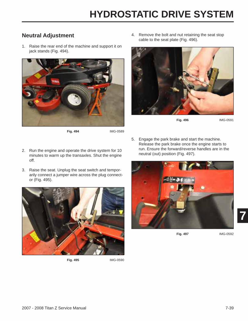
HYDROSTATIC DRIVE SYSTEM
7-392007 - 2008 Titan Z Service Manual
7
Neutral Adjustment
1. Raise the rear end of the machine and support it on jack stands (Fig. 494).
4. Remove the bolt and nut retaining the seat stop cable to the seat plate (Fig. 496).
Fig. 494 IMG-0589
2. Run the engine and operate the drive system for 10 minutes to warm up the transaxles. Shut the engine off.
3. Raise the seat. Unplug the seat switch and tempor-arily connect a jumper wire across the plug connect-or (Fig. 495).
Fig. 495 IMG-0590
Fig. 496 IMG-0591
5. Engage the park brake and start the machine. Release the park brake once the engine starts to run. Ensure the forward/reverse handles are in the neutral (out) position (Fig. 497).
Fig. 497 IMG-0592
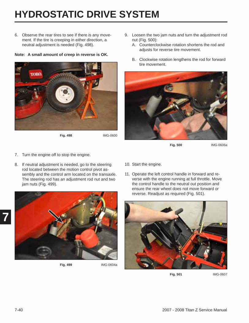
HYDROSTATIC DRIVE SYSTEM
7-40 2007 - 2008 Titan Z Service Manual
7
6. Observe the rear tires to see if there is any move-ment. If the tire is creeping in either direction, a neutral adjustment is needed (Fig. 498).
Note: A small amount of creep in reverse is OK.
9. Loosen the two jam nuts and turn the adjustment rod nut (Fig. 500):A. Counterclockwise rotation shortens the rod and
adjusts for reverse tire movement.
B. Clockwise rotation lengthens the rod for forward tire movement.
Fig. 498 IMG-0600
Fig. 500 IMG-0606a
10. Start the engine.
11. Operate the left control handle in forward and re-verse with the engine running at full throttle. Move the control handle to the neutral out position and ensure the rear wheel does not move forward or reverse. Readjust as required (Fig. 501).
Fig. 501 IMG-0607
7. Turn the engine off to stop the engine.
8. If neutral adjustment is needed, go to the steering rod located between the motion control pivot as-sembly and the control arm located on the transaxle. The steering rod has an adjustment rod nut and two jam nuts (Fig. 499).
Fig. 499 IMG-0604a
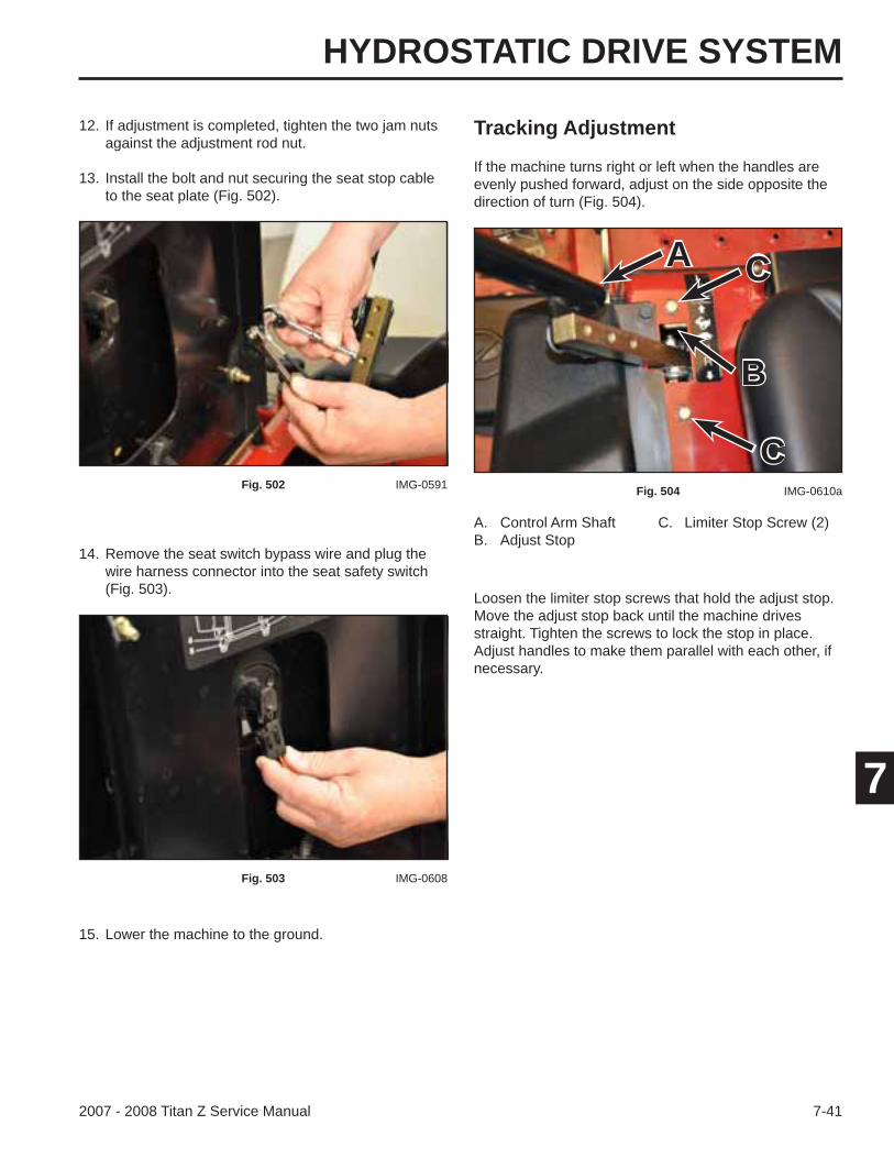
HYDROSTATIC DRIVE SYSTEM
7-412007 - 2008 Titan Z Service Manual
7
Loosen the limiter stop screws that hold the adjust stop. Move the adjust stop back until the machine drives straight. Tighten the screws to lock the stop in place. Adjust handles to make them parallel with each other, if necessary.
A. Control Arm Shaft C. Limiter Stop Screw (2)B. Adjust Stop
12. If adjustment is completed, tighten the two jam nuts against the adjustment rod nut.
13. Install the bolt and nut securing the seat stop cable to the seat plate (Fig. 502).
If the machine turns right or left when the handles are evenly pushed forward, adjust on the side opposite the direction of turn (Fig. 504).
Fig. 502 IMG-0591 Fig. 504 IMG-0610a
14. Remove the seat switch bypass wire and plug the wire harness connector into the seat safety switch (Fig. 503).
Fig. 503 IMG-0608
15. Lower the machine to the ground.
Tracking Adjustment
A
B
C
C
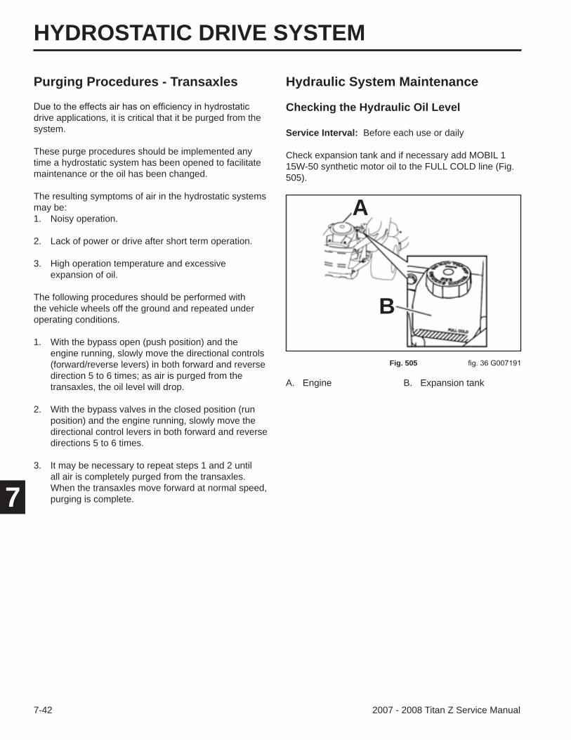
HYDROSTATIC DRIVE SYSTEM
7-42 2007 - 2008 Titan Z Service Manual
7
Purging Procedures - Transaxles Hydraulic System Maintenance
Checking the Hydraulic Oil Leveldrive applications, it is critical that it be purged from the system.
These purge procedures should be implemented any time a hydrostatic system has been opened to facilitate maintenance or the oil has been changed.
The resulting symptoms of air in the hydrostatic systems may be:1. Noisy operation.
2. Lack of power or drive after short term operation.
3. High operation temperature and excessive expansion of oil.
The following procedures should be performed with the vehicle wheels off the ground and repeated under operating conditions.
1. With the bypass open (push position) and the engine running, slowly move the directional controls (forward/reverse levers) in both forward and reverse direction 5 to 6 times; as air is purged from the transaxles, the oil level will drop.
2. With the bypass valves in the closed position (run position) and the engine running, slowly move the directional control levers in both forward and reverse directions 5 to 6 times.
3. It may be necessary to repeat steps 1 and 2 until all air is completely purged from the transaxles. When the transaxles move forward at normal speed, purging is complete.
A. Engine B. Expansion tank
Service Interval: Before each use or daily
Check expansion tank and if necessary add MOBIL 1 15W-50 synthetic motor oil to the FULL COLD line (Fig. 505).
Fig. 505
A
B
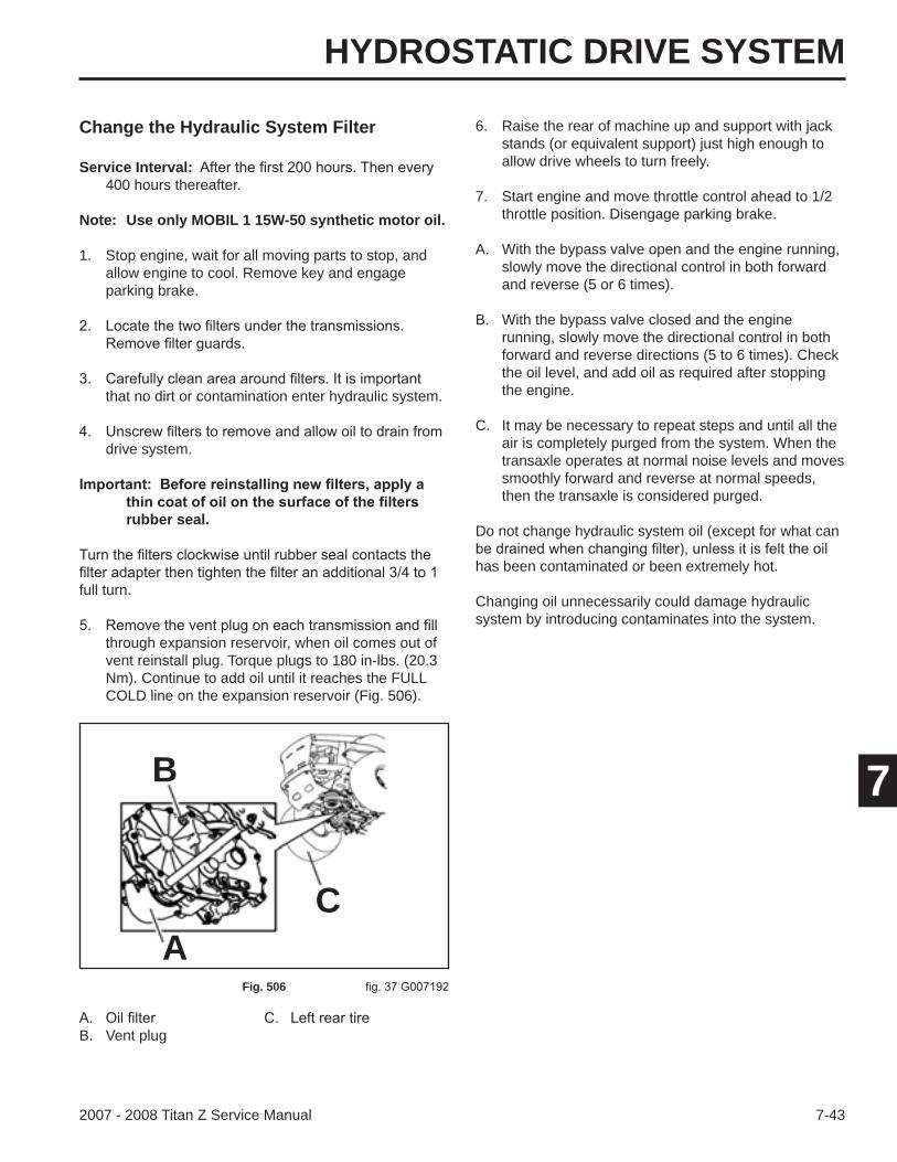
HYDROSTATIC DRIVE SYSTEM
7-432007 - 2008 Titan Z Service Manual
7
Change the Hydraulic System Filter
B. Vent plug
Service Interval:400 hours thereafter.
Note: Use only MOBIL 1 15W-50 synthetic motor oil.
1. Stop engine, wait for all moving parts to stop, and allow engine to cool. Remove key and engage parking brake.
that no dirt or contamination enter hydraulic system.
drive system.
rubber seal.
full turn.
through expansion reservoir, when oil comes out of vent reinstall plug. Torque plugs to 180 in-lbs. (20.3 Nm). Continue to add oil until it reaches the FULL COLD line on the expansion reservoir (Fig. 506).
Fig. 506
A
B
C
6. Raise the rear of machine up and support with jack stands (or equivalent support) just high enough to allow drive wheels to turn freely.
7. Start engine and move throttle control ahead to 1/2 throttle position. Disengage parking brake.
A. With the bypass valve open and the engine running, slowly move the directional control in both forward and reverse (5 or 6 times).
B. With the bypass valve closed and the engine running, slowly move the directional control in both forward and reverse directions (5 to 6 times). Check the oil level, and add oil as required after stopping the engine.
C. It may be necessary to repeat steps and until all the air is completely purged from the system. When the transaxle operates at normal noise levels and moves smoothly forward and reverse at normal speeds, then the transaxle is considered purged.
Do not change hydraulic system oil (except for what can
has been contaminated or been extremely hot.
Changing oil unnecessarily could damage hydraulic system by introducing contaminates into the system.
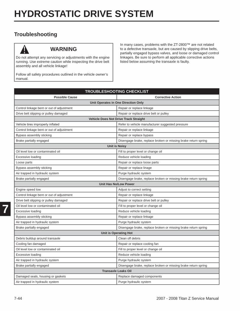
HYDROSTATIC DRIVE SYSTEM
7-44 2007 - 2008 Titan Z Service Manual
7
Troubleshooting
WARNINGDo not attempt any servicing or adjustments with the engine running. Use extreme caution while inspecting the drive belt assembly and all vehicle linkage!
Follow all safety procedures outlined in the vehicle owner’s manual.
In many cases, problems with the ZT-2800™ are not related to a defective transaxle, but are caused by slipping drive belts, partially engaged bypass valves, and loose or damaged control linkages. Be sure to perform all applicable corrective actions listed below assuming the transaxle is faulty.
TROUBLESHOOTING CHECKLISTPossible Cause Corrective Action
Unit Operates in One Direction OnlyControl linkage bent or out of adjustment Repair or replace linkage
Drive belt slipping or pulley damaged Repair or replace drive belt or pulley
Vehicle Does Not Drive Track StraightRefer to vehicle manufacturer suggested pressure
Control linkage bent or out of adjustment Repair or replace linkage
Bypass assembly sticking Repair or replace bypass
Brake partially engaged Disengage brake, replace broken or missing brake return spring
Unit is NoisyOil level low or contaminated oil Fill to proper level or change oil
Excessive loading Reduce vehicle loading
Loose parts Repair or replace loose parts
Bypass assembly sticking Repair or replace linage
Air trapped in hydraulic system Purge hydraulic system
Brake partially engaged Disengage brake, replace broken or missing brake return spring
Unit Has No/Low PowerEngine speed low Adjust to correct setting
Control linkage bent or out of adjustment Repair or replace linkage
Drive belt slipping or pulley damaged Repair or replace drive belt or pulley
Oil level low or contaminated oil Fill to proper level or change oil
Excessive loading Reduce vehicle loading
Bypass assembly sticking Repair or replace linkage
Air trapped in hydraulic system Purge hydraulic system
Brake partially engaged Disengage brake, replace broken or missing brake return spring
Unit is Operating HotDebris buildup around transaxle Clean off debris
Cooling fan damaged Repair or replace cooling fan
Oil level low or contaminated oil Fill to proper level or change oil
Excessive loading Reduce vehicle loading
Air trapped in hydraulic system Purge hydraulic system
Brake partially engaged Disengage brake, replace broken or missing brake return spring
Transaxle Leaks OilDamaged seals, housing or gaskets Replace damaged components
Air trapped in hydraulic system Purge hydraulic system
!
2007 - 2008Titan™ Z4800 & Z5200
Service Manual
Form No. 492-9207