2006/2007 CHIONG CHUNG ENG - Universiti Teknologi...
29
STRENGTHENING OF BOLTED SHEAR JOINT IN FERROCEMENT CONSTRUCTION 2006/2007 CHIONG CHUNG ENG 70F, Lorong 14, Jalan Nanas Barat, 93400 Kuching, Sarawak. PROF. DR. M. A. MANSUR 2 JULY 2007 2 JULY 2007
Transcript of 2006/2007 CHIONG CHUNG ENG - Universiti Teknologi...
STRENGTHENING OF BOLTED SHEAR JOINT IN FERROCEMENT CONSTRUCTION
2006/2007
CHIONG CHUNG ENG
70F, Lorong 14, Jalan Nanas Barat, 93400 Kuching, Sarawak.
PROF. DR. M. A. MANSUR
2 JULY 2007 2 JULY 2007
“We hereby declare that we have read through this project report and to our opinion
this report is adequate in terms of scope and quality for the purpose of awarding the
degree of Master of Engineering (Civil - Structure)”
Signature : ....................................................
Name of Supervisor I : PROF. DR. M. A. MANSUR
Date : 2 JULY 2007
Signature : ....................................................
Name of Supervisor II : PM. DR. MOHD. ISMAIL
Date : 2 JULY 2007

STRENGTHENING OF BOLTED SHEAR JOINT IN FERROCEMENT
CONSTRUCTION
CHIONG CHUNG ENG
A project report submitted in a partial fulfillment of the
requirement for the award of degree of
Master of Engineering (Civil – Structure)
Faculty of Civil Engineering
Universiti Teknologi Malaysia
JULY, 2007

ii
“I declare that this project report entitled “Strengthening of Bolted Shear Joint in
Ferrocement Construction” is the result of my own study except as cited in the
references. This thesis has not been accepted for any degree and is not concurrently
submitted in candidature of any other degree.”
Signature : ………………………………….
Author : CHIONG CHUNG ENG
Date : 2 JULY 2007
iii
To my beloved father and mother, family and dear friends.
iv
ACKNOWLEDGEMENTS
Firstly, the author wishes to express utmost gratitude to his project supervisor,
Professor Dr. M. A. Mansur for his patient guidance and valuable advice given
throughout the planning and execution of the research. With his encouragement and
help, the author even has the chance to publish a paper in the international journal. This
is a special achievement that the author never thinks of before in his life.
Secondly, the author also greatly appreciates his co-supervisor, Associate
Professor Dr. Mohd. Ismail for his valuable comments and advice given throughout the
process of writing this report. His care and help to the author will not be forgotten.
Besides that, the author would also like to express his gratefulness to his PHD
senior, Mr. Noor Ahmed for his advice and supplying of tools throughout the laboratory
work of the research. His help has caused the author to save lots of time and money and
most important prevent the author from making mistake during laboratory work.
The friendly and helpful technical staffs of the structural and material laboratory
of Universiti Teknologi Malaysia, especially Mr. Jaafar and Mr. Razale also deserve a
note of appreciation from the author. With their helps and supervisions, the author
managed to operate very delicate machinery smoothly during testing.
Then, the author wishes to show his appreciation to Ms. Angela bt. Mohd Sabah,
Sales Manager of BASF Construction Chemical Malaysia Sdn. Bhd. for showing her
kind and generosity in providing the author with concrete admixtures free of charge.
With due respects, the author remembers her parents and friends on their
countless blessings and supports which have always been a source of inspiration in
achieving success to this level.

v
ABSTRACT
This study deals with strengthening of bolted shear joint in thin-walled
ferrocement construction. Such a joint is attractive because it provides faster and neat
means of assembling precast elements into a complete structure. Steel wires, bent into
O-Shape and U-shape with or without extra straight wire, are considered as simple
inserts around the bolt hole to enhance the joint strength. The parameters investigated
include the number of layers of wire mesh (or volume fraction of reinforcement), edge
distance of bolt hole and the effectiveness of different types of the steel inserts. Test
results have shown that for small edge distance, failure occurs either in cleavage or
shearing mode, and the strength of the joint increases with an increase in the edge
distance. This continues up to an upper limit set by either tension or bearing failure. For
a given edge distance and details of connected members, the strength of a joint can be
significantly enhanced by using steel insert, while U-insert is most cost-effective.
Available equations for predicting the joint strength in ferrocement composites can be
slightly modified to include the effects of these inserts with a good level of accuracy.
Since the cleavage failure equation is quite conservative, removing it from consideration
or modifying it to reflect test data can improve the accuracy of the predictions of joint
strength. As an alternative, strut-and-tie model, herein can predict the joint strength in
ferrocement composite as proposed. However it does not perform that well if steel insert
is included in the ferrocement plate, as the process to determine volume fraction of
reinforcement becomes more complex.

vi
ABSTRAK
Kajian ini adalah berkenaan sambungan ricih bolt dalam pembinaan dinding
nipis ferrocement. Sambungan bolt sesuai kerana ia adalah cepat dan tersusun semasa
menyambungkan elemen precast kepada suatu struktur yang menyeluruh. Dawai besi,
yang dibengkokkan kepada bentuk O dan U yang ditambah atau tidak ditambah dengan
dawai lurus, telah digunakan sebagai tetulang tambahan disekeliling bolt untuk
meningkatkan kekuatan sambungan. Parameter yang dikaji termasuk bilangan lapisan
jejaring dawai (atau peratus isipadu tetulang), jarak ke tepi dari lubang bolt dan
kesesuaian tetulang tambahan besi yang berlainan. Keputusan ujian menunjukkan untuk
jarak tepi yang kecil, kegagalan dalam “cleavage” atau rich berlaku. Kekuatan
sambungan meningkat apabila jarak tepi bertambah. Ini berterusan sehingga satu tahap
apabila kegagalan tegangan atau galas berlaku. Untuk jarak tepi dan keadaan
sambungan yang ditetapkan, kekuatan sambungan boleh ditingkatkan keberkesannya
dengan penggunaan tetulang tambahan besi, manakala tetulang tambahan bentuk U
adalah paling kos-efektif. Formula yang ada untuk menjangka kekuatan komposit
ferrocement boleh diubah sedikit untuk menambahkan kesan tetulang tambahan dengan
ketepatan yang baik. Oleh kerana formula untuk kegagalan “cleavage” sangat
konservatif, pengeluaran formula “cleavage” dalam pertimbangan atau pengubahsuaian
formula tersebut dapat meningkatkan ketepatan jangkaan kekuatan sambungan. Modal
strut-and-tie merupakan satu cara lain untuk menjangka kekuatan sambungan komposit
ferrocement. Tetapi keputusannya menjadi kurang tepat jika tetulang tambahan
digunakan dalam komposit ferrocement. Ini disebabkan pengiraan peratus isipadu
tetulang untuknya adalah sukar.
vii
TABLE OF CONTENTS
CHAPTER TITLE PAGE
AUTHOR DECLARATION ii
DEDICATION iii
ACKNOWLEDGEMENTS iv
ABSTRACT v
ABSTRAK vi
TABLE OF CONTENTS vii
LIST OF TABLES x
LIST OF FIGURES xi
LIST OF APPENDICES xv
1 INTRODUCTION 1 1.1 Research Problem 2
1.2 Objective 2
1.3 Scope of Project 3
2 LITERATURE REVIEW 4 2.1 Ferrocement and Its Application 4
2.2 Industrialized Ferrocement Housing System 5
2.3 Basic Failure Modes and Equations in Bolted Shear Joint 6

viii
2.3.1 Shear Failure Mode 6
2.3.2 Tension Failure Mode 7
2.3.3 Cleavage Failure Mode 7
2.3.4 Bearing Failure Mode 8
2.4 Strengthening of Bolted Shear Joint 8
2.5 Strut-and-Tie Model 9
3 METHODOLOGI 16 3.1 Detail of Test Program 17
3.1.1 Materials 18
3.1.2 Preparation of Specimens 20
3.1.3 Test Setup, Instrumentation and Test Procedure 21
3.2 Predict Failure Loads of Test Program by Equations 22
3.3 Strut-and-Tie Model for Bolted Shear Joint 24
3.3.1 Compressive Strut Width, b 25
3.3.2 Effectiveness Factor of Concrete, v 26
3.4 Verification of Data from Available Journal 26
3.5 Modification of Cleavage Failure Equation 27
4 DATA COLLECTION AND ANALYSIS 35 4.1 Introduction 35
4.2 Yield Strength of Wire Mesh and Steel Bar 36
4.3 Test Program Results 36
4.3.1 Prediction of results by Failure Mode Equations 36
4.3.2 Prediction of results by Strut-and-Tie Model 37
4.3.3 Experimental Results 37
4.4 Analysis of Test Data from Available Journal 37
4.5 Modification of Cleavage Failure Equation 38
5 DISCUSSION OF RESULTS 47 5.1 Introduction 47

ix
5.2 Test Program Results 47
5.2.1 General Behavior 48
5.2.2 Effects of Volume Fraction of Reinforcement, Vf 49
5.2.3 Effect of Edge Distance, e 50
5.2.4 Effect of Steel Insert in Shear Joint of Ferrocement
Plate 51
5.2.5 Comparison of Experimental Results with
Theoretical Predictions 52
5.3 Analysis of Test Data Available 55
5.4 Effects of Using Modified Cleavage Equation 56
6 CONCLUSIONS AND RECOMMENDATIONS 66 6.1 Conclusions 66
6.2 Recommendations for Further Research 68
REFERENCES 69
Appendices 71 - 102
x
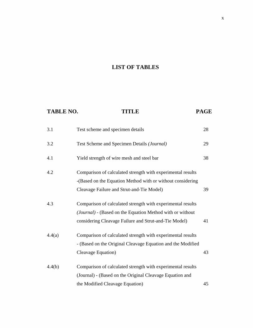
LIST OF TABLES
TABLE NO. TITLE PAGE
3.1 Test scheme and specimen details 28
3.2 Test Scheme and Specimen Details (Journal) 29
4.1 Yield strength of wire mesh and steel bar 38
4.2 Comparison of calculated strength with experimental results
-(Based on the Equation Method with or without considering
Cleavage Failure and Strut-and-Tie Model) 39
4.3 Comparison of calculated strength with experimental results
(Journal) - (Based on the Equation Method with or without
considering Cleavage Failure and Strut-and-Tie Model) 41
4.4(a) Comparison of calculated strength with experimental results
- (Based on the Original Cleavage Equation and the Modified
Cleavage Equation) 43
4.4(b) Comparison of calculated strength with experimental results
(Journal) - (Based on the Original Cleavage Equation and
the Modified Cleavage Equation) 45
xi
LISTS OF FIGURES
FIGURE NO. TITLE PAGE
2.1 Production of ferrocement 11
2.2 Original 1848 boat in Brignoles Museum 11
2.3 Innovative use of ferrocement 12
2.4 Ferrocement sunscreens in Singapore 12
2.5 Precast ferrocement panels 13
2.6 Assembly of ferrocement panels 13
2.7 Bolted joints at different location 14
2.8 Components acting on bolted joint 14
2.9 Four basic modes of failure 15
2.10 Strut-and-tie model for a deep beam 15
xii
2.11 Compression struts 15
3.1 Dimensions of sample 30
3.2 Diagram of test setup 30
3.3 Detail of specimen series 30
3.4 Mesh sample and steel bar under testing 31
3.5 Moulds with wire mesh bundle within 31
3.6 Freshly-cast specimens and final specimens 32
3.7 Dartec machine 32
3.8 Test setup of the specimen 32
3.9 Strut-and-tie Model for ferrocement shear joint 33
3.10 Strut-and-tie model at Staad Pro to get ratio of P 33
3.11 Compression struts for ferrocement shear joint 34
5.1 Effect of volume fraction of reinforcement on the strength
of the joint 57
5.2(a) Effect of Type A insert on the strength of the joint 57
5.2(b) Effect of Type B insert and Type C insert on the strength
of the joint 58
xiii
5.3(a) Comparison of experimental results with predicted results
for V2-E 58
5.3(b) Comparison of experimental results with predicted results
for V5-E 59
5.3(c) Comparison of experimental results with predicted results for
V2-D4-E 59
5.3(d) Comparison of experimental results with predicted results
for V1-E 60
5.3(e) Comparison of experimental results with predicted results
for V3-E 60
5.3(f) Comparison of experimental results with predicted results
for V1-D3-E 61
5.3(g) Comparison of Experimental Results with Predicted Results
for V1-D3-T-E 61
5.4 Comparison between experimental and calculated ultimate
strengths by Equation Method (Considering
Cleavage Failure) 62
5.5 Comparison between experimental and calculated ultimate
strengths by Equation Method (Without Considering
Cleavage Failure) 63
5.6 Comparison between experimental and calculated ultimate
strengths by Strut-and-Tie Model (Without Steel Insert) 64

xiv
5.7 Comparison between experimental and calculated ultimate
strengths by Modified Cleavage Failure Equation 65
xv
LISTS OF APPENDICES
APPENDIX TITLE PAGE
A1 Yield strength of 1.60 mm diameter wire mesh 72
(Specimen 1)
A2 Yield strength of 1.60 mm diameter wire mesh 72
(Specimen 2)
A3 Yield strength of 1.60 mm diameter wire mesh 73
(Specimen 3)
A4 Yield strength of 1.42 mm diameter wire mesh 73
(Specimen 1)
A5 Yield strength of 1.42 mm diameter wire mesh 74
(Specimen 2)
A6 Yield strength of 1.42 mm diameter wire mesh 74
(Specimen 3)
A7 Yield strength of 3.60 mm diameter steel wire 75
(Specimen 1)
xvi
A8 Yield strength of 3.60 mm diameter steel wire 75
(Specimen 2)
A9 Yield strength of 3.60 mm diameter steel wire 76
(Specimen 3)
A10 Yield strength of 4.00 mm diameter steel wire 76
(Specimen 1)
A11 Yield strength of 4.00 mm diameter steel wire 77
(Specimen 2)
A12 Yield strength of 4.00 mm diameter steel wire 77
(Specimen 3)
B1 Design Mix for Mortar A 79
B2 Design Mix for Mortar B 80
C1 Load – displacement curves of Series V2- E 83
C2 Load – displacement curves of Series V5- E 84
C3 Load – displacement curves of Series V2-D4-E 85
C4 Load – displacement curves of Series V1- E 86
C5 Load – displacement curves of Series V3- E 87
C6 Load – displacement curves of Series V1-D3-E 88
C7 Load – displacement curves of Series V1-D3-T-E 89
D1 Failure mode for Series V2-E 91
xvii
D2 Failure mode for Series V5-E 91
D3 Failure mode for Series V2-D4-E 91
D4 Failure mode for Series V1-E 92
D5 Failure mode for Series V3-E 92
D6 Failure mode for Series V1-D3-E 93
D7 Failure mode for Series V1-D3-T-E 93
E1(a) Predicted Results by Failure Mode Equations
(With Considering Cleavage Failure) 95
E1(b) Predicted Results by Failure Mode Equations
(Without Considering Cleavage Failure) 96
E2 Predicted Results by Strut-and-Tie Model 97
E3(a) Predicted Results by Failure Mode Equations (Journal)
(With Considering Cleavage Failure) 98
E3(b) Predicted Results by Failure Mode Equations (Journal)
(Without Considering Cleavage Failure) 99
E4 Predicted Results by Strut-and-Tie Model (Journal) 100
E5(a) Predicted Results by Failure Mode Equations
(Modified Cleavage Failure Equation) 101
E5(b) Predicted Results by Failure Mode Equations (Journal)
(Modified Cleavage Failure Equation) 102

1
CHAPTER 1
INTRODUCTION
Ferrocement is a type of thin reinforced-concrete construction where instead
of reinforcing bars, larger amount of smaller diameter wire meshes are used
uniformly throughout the cross section and, instead of concrete, mortar is used
(Surendra & Naaman, 1978). The ferrocement technique was invented about 160
years ago by Joseph Lambot when he constructed the first ferrocement boat at
Brignoles, France in 1848.
Recently, due to increasing labour cost and the need for producing high
quality construction material, Industrialized Building System (IBS) is introduced.
The system encourages structural components to be manufactured in the factory in
mass quantity and assemble them on site by using suitable connections. Ferrocement
can be fabricated into any desired shape and, being a thin-walled composite, the
components will be lighter for handling and transportation. Assembling these
components by using bolted joints will eliminate the requirement for messy wet
connection on site and greatly expedite the construction process. The ACI
Committee 549 had provided design guide for the fabrication of ferrocement, but
there is still a lack of information on bolted connections in precast ferrocement
panels.
2
Since 1994, a number of research programs on the behaviour and strength of
bolted joint in ferrocement has been conducted at the National University of
Singapore (Mansur et. al., 1994, 2001, Abdullah and Mansur, 1995, Tan, 1999).
These investigations identified four different modes of failure for a shear joint and
attempted to develop analytical models for predicting the ultimate strength of such a
joint. A careful review of the resulting expressions reveal that, for a given geometry
and connected member details, joint strength may be enhanced significantly by
incorporating simple steel insert of desired shape at suitable location. The focus of
this study has therefore been directed toward strengthening of bolted shear joint in
ferrocement construction.
1.1 Research Problem
This study concentrates mainly on the problem of identifying the effect of
steel inserts on bolted shear joint and their effectiveness in strengthening bolted shear
joint.
1.2 Objectives
The objectives of the study are:-
a) To propose suitable ways to strengthen bolted shear joint using steel insert by
investigating the available mechanistic models and modifying the models for
incorporation of inserts.

3
b) To verify experimentally the effectiveness of the strengthening method by
designing and conducting a series of tests and comparing with the analytical
predictions.
1.3 Scope of Project
This research was aimed to propose suitable way to strengthen bolted shear
joint. To archive that, some literature study had been done and the equations of four
mode of failure were analyzed to see the relationship of the parameters involved. A
strut-and-tie model was also constructed to achieve that purpose. From the analysis,
steel inserts could significantly increase the strength of the joint. Furthermore, tests
on the steel inserts on bolted shear were conducted to verify its effectiveness.
4
CHAPTER 2
LITERATURE REVIEW
2.1 Ferrocement and Its Application
Ferrocement is a type of thin-wall reinforced concrete commonly constructed
of cement-sand mortar with closely spaced layers of continuous and small diameter
mesh bound together. The ferrocement technique was first used by Joseph Lambot
when he constructed his first ferrocement boat at Brignoles, France in 1848. Fig. 2.1
showed the production of ferrocement. Fig. 2.2 showed the first ferrocement boat
constructed by Joseph Lambot.
Ferrocement was used for boat building in Bangladesh, China, India,
Indonesia and Thailand due to timber shortages and the availability of cheap labour
(Shah and Naaman, 1978). Being efficient in the crack arresting property,
ferrocement was suitable to be used in water resource applications, such as water
tank, casing for well and sedimentation tank. Besides, ferrocement was considered
as a suitable construction material for housing in developing countries (Naaman,
1998). It was used as precast elements for roofing, wall panels, fences and
sunshades. These precast elements were chosen for its low self-weight, avoidance of
5
formwork and availability of cheap labour. In 1987, large scale application of
ferrocement was held in Singapore (Mansur et. al., 1987). Ferrocement was used to
build sunscreens for modern multi-storey apartment blocks. Fig. 2.3 shows
innovative application of ferrocement while Fig. 2.4 shows ferrocement sunscreens
for apartment block in Singapore.
2.2 Industrialized Ferrocement Housing System
An industrialized two-storey housing system proposed in the literature
consists of precast ferrocement panels of different sizes (Naaman, 2000). They are
wall panel, corner panel, window panel, floor panel, ceiling panel and window panel.
These panels can be easily manufactured in a precasting yard under strict quality
control and sent to the site for assembling. In order to avoid messy and slow wet
connection on site, bolted joints was proposed to assemble the precast panels into
complete structure. Fig. 2.5 showed diagram of the precast ferrocement panels.
Assembly of panels using bolted joints are shown in Fig. 2.6 and Fig. 2.7.
A careful review of joints in such a housing system reveals that the forces
transmitted through the joints consists of shear force, axial force and bending
moment, and accordingly, the joint are classified as shear joint, axial joint and
moment joint, as shown in Fig.2.8. This study deals with shear joints only as it is one
of the most common type of joints in such a structural system.
6
2.3 Basic Failure Modes and Equations in Bolted Shear Joint
When a bolted shear joint is subjected to tensile load, four modes of failure
have been identified by previous researchers (Mansur et. al., 1994, 2001, Abdullah
and Mansur, 1995, Tan, 1999). These are (refer to Fig. 2.9):-
a) Shear Failure
b) Tension Failure
c) Cleavage Failure
d) Bearing Failure
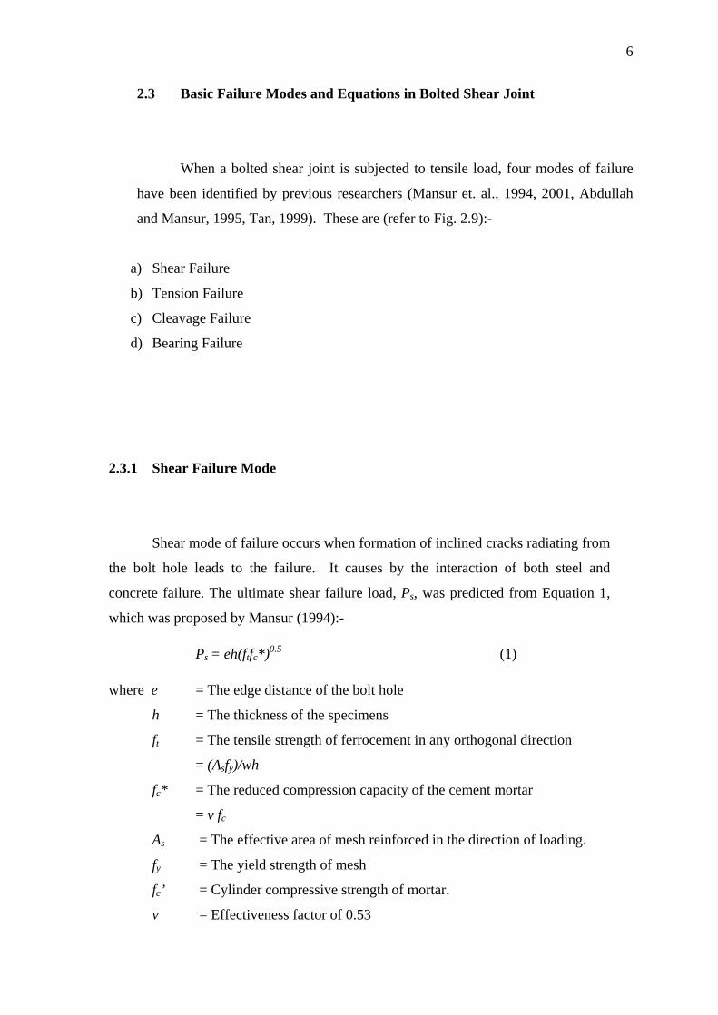
2.3.1 Shear Failure Mode
Shear mode of failure occurs when formation of inclined cracks radiating from
the bolt hole leads to the failure. It causes by the interaction of both steel and
concrete failure. The ultimate shear failure load, Ps, was predicted from Equation 1,
which was proposed by Mansur (1994):-
Ps = eh(ftfc*)0.5 (1) where e = The edge distance of the bolt hole
h = The thickness of the specimens
ft = The tensile strength of ferrocement in any orthogonal direction
= (Asfy)/wh
fc* = The reduced compression capacity of the cement mortar
= v fc
As = The effective area of mesh reinforced in the direction of loading.
fy = The yield strength of mesh
fc’ = Cylinder compressive strength of mortar.
v = Effectiveness factor of 0.53
7
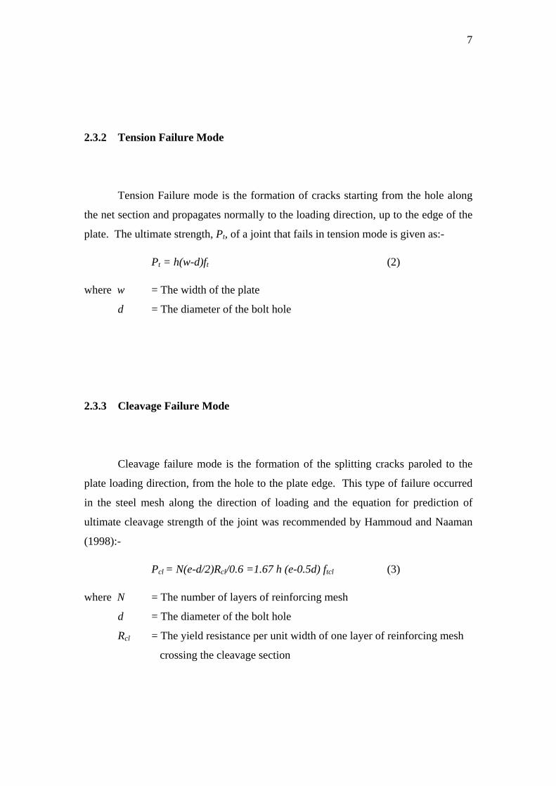
2.3.2 Tension Failure Mode
Tension Failure mode is the formation of cracks starting from the hole along
the net section and propagates normally to the loading direction, up to the edge of the
plate. The ultimate strength, Pt, of a joint that fails in tension mode is given as:-
Pt = h(w-d)ft (2)
where w = The width of the plate
d = The diameter of the bolt hole
2.3.3 Cleavage Failure Mode
Cleavage failure mode is the formation of the splitting cracks paroled to the
plate loading direction, from the hole to the plate edge. This type of failure occurred
in the steel mesh along the direction of loading and the equation for prediction of
ultimate cleavage strength of the joint was recommended by Hammoud and Naaman
(1998):-
Pcl = N(e-d/2)Rcl/0.6 =1.67 h (e-0.5d) ftcl (3)
where N = The number of layers of reinforcing mesh
d = The diameter of the bolt hole
Rcl = The yield resistance per unit width of one layer of reinforcing mesh
crossing the cleavage section
8
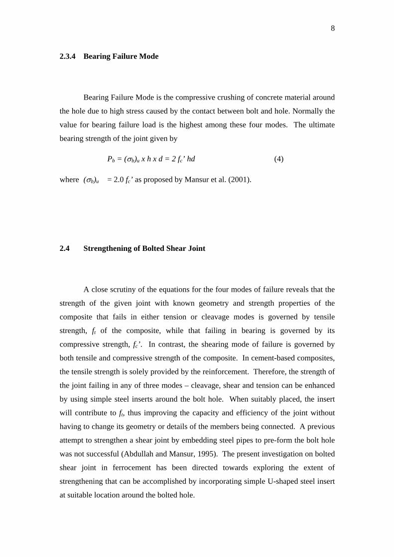
2.3.4 Bearing Failure Mode
Bearing Failure Mode is the compressive crushing of concrete material around
the hole due to high stress caused by the contact between bolt and hole. Normally the
value for bearing failure load is the highest among these four modes. The ultimate
bearing strength of the joint given by
Pb = (σb)u x h x d = 2 fc’ hd (4)
where (σb)u = 2.0 fc’ as proposed by Mansur et al. (2001).
2.4 Strengthening of Bolted Shear Joint
A close scrutiny of the equations for the four modes of failure reveals that the
strength of the given joint with known geometry and strength properties of the
composite that fails in either tension or cleavage modes is governed by tensile
strength, ft of the composite, while that failing in bearing is governed by its
compressive strength, fc’. In contrast, the shearing mode of failure is governed by
both tensile and compressive strength of the composite. In cement-based composites,
the tensile strength is solely provided by the reinforcement. Therefore, the strength of
the joint failing in any of three modes – cleavage, shear and tension can be enhanced
by using simple steel inserts around the bolt hole. When suitably placed, the insert
will contribute to ft, thus improving the capacity and efficiency of the joint without
having to change its geometry or details of the members being connected. A previous
attempt to strengthen a shear joint by embedding steel pipes to pre-form the bolt hole
was not successful (Abdullah and Mansur, 1995). The present investigation on bolted
shear joint in ferrocement has been directed towards exploring the extent of
strengthening that can be accomplished by incorporating simple U-shaped steel insert
at suitable location around the bolted hole.
9
2.5 Strut-and-Tie Model
Besides using equations, strut-and-tie model is an alternative model for
estimating the tensile stress resultant for a concrete structure. This model assumes
that in a cracked member, concrete in between the cracks carries direct compression
and steel carries axial tension. The load-carrying mechanism of the member can then
be idealized as that of a truss comprising a series of concrete struts and steel ties.
Known as the strut-and-tie model, this concept of idealization has been found to be a
simple, but powerful tool dealing with disturbed or discontinuous regions of a
concrete structure (MacGregor, 1997).
Strut-and-tie model is a system of forces in equilibrium with a given set of
loads. The lower bound theorem of plasticity states that the capacity of such a system
of forces is the lower bound on the strength of the structure, provided that no element
is loaded beyond its capacity. This assumes that deformation capacity is not exceeded
at any point before the assumed system of forces is reached. For this reason, the
resultant forces in the members of the strut-and-tie model should be close to the final
set of the internal forces.
A simple strut-and-tie model for a deep beam is shown in Fig. 2.10. It consists
of concrete compressive struts, reinforcing bars as tension ties, and joints and nodal
zones.
(a) Compression Strut
In a strut-and-tie model the strut represent concrete compression stress fields
with the prevailing compression in the direction of the strut. Struts are frequently
idealized as prismatic or uniformly tampering members, but often vary in cross

10
section along their lengths (Fig. 2.11) because the concrete is wider at midlength of
the strut than at the ends.
(b) Tension Ties
The spreading of the compression forces gives rise to transverse tensions,
which may cause the strut to crack longitudinally. If the strut has no transverse
reinforcement, it may fail after this cracking occurs. If adequate transverse
reinforcement is provided, the strut will fail by crushing,
Tension ties represent one or several layers of steel reinforcement which resist
these tension forces. Tension ties may fail due to lack of end anchorage. The
anchorage of the ties in the nodal zone is a major part of the design of D-region using
a strut-and-tie model.
(c) Nodal Zones
Nodal zones are the joints in strut-and-ties model. Here three or more forces
meet at a node and these forces must be in equilibrium.