20060108 Product Technology...
64
TECHNICAL TRAINING PRODUCT TECHNOLOGY - HANDHELD PRODUCTS
Transcript of 20060108 Product Technology...

TECHNICAL TRAININGPRODUCT TECHNOLOGY - HANDHELD PRODUCTS

2

1
Product Technology
Engine techniques...........................................................................3
Crankcase..........................................................................................7
Crankshaft........................................................................................9
Cylinder..........................................................................................15
Piston..............................................................................................19
Fuel systems...................................................................................27
Lubrication systems......................................................................35
Ignition systems.............................................................................41
Drive systems.................................................................................47
Protective equipment....................................................................49
Personal protective equipment.....................................................55
Ergonomics....................................................................................57
Environment..................................................................................59

2
3
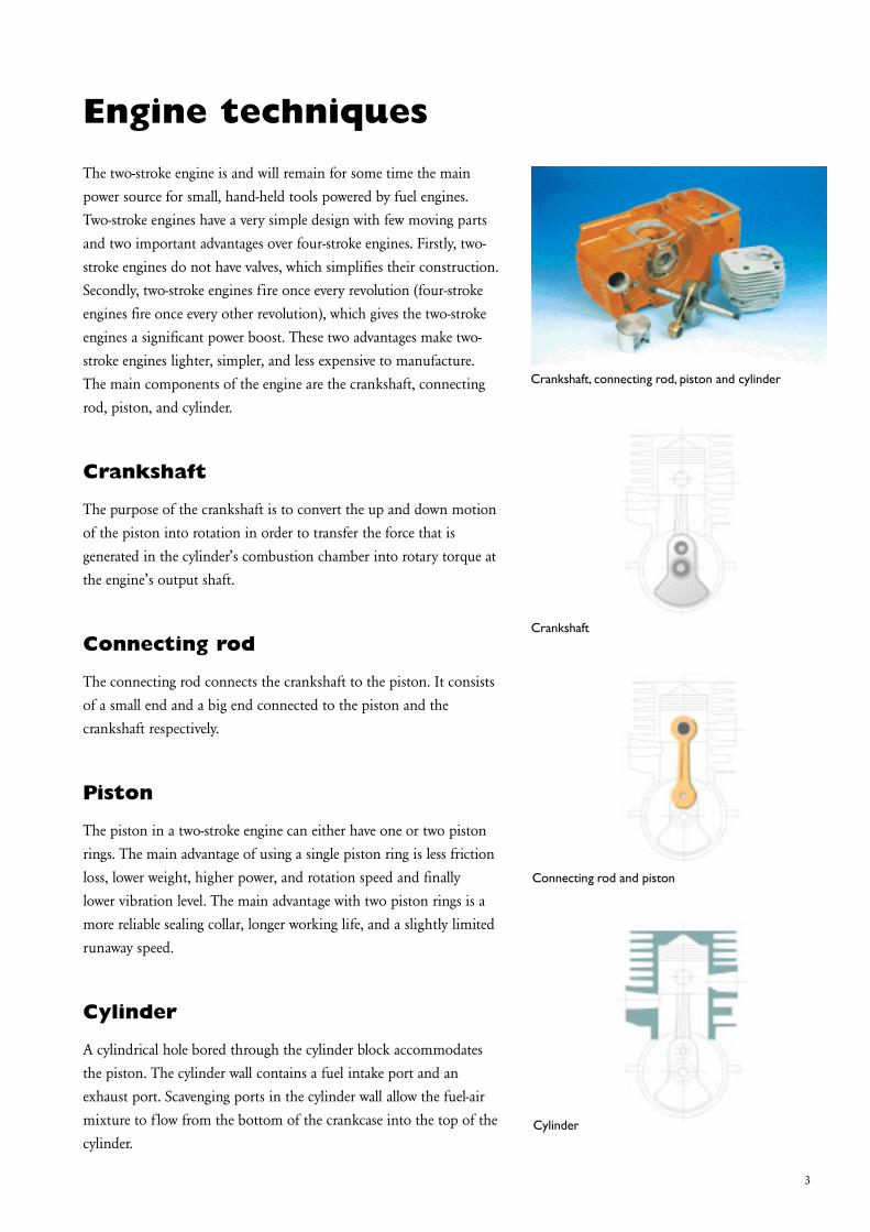
Crankshaft, connecting rod, piston and cylinder
Crankshaft
Connecting rod and piston
Cylinder
Engine techniquesThe two-stroke engine is and will remain for some time the main power source for small, hand-held tools powered by fuel engines. Two-stroke engines have a very simple design with few moving parts and two important advantages over four-stroke engines. Firstly, two-stroke engines do not have valves, which simplifies their construction. Secondly, two-stroke engines fire once every revolution (four-stroke engines fire once every other revolution), which gives the two-stroke engines a significant power boost. These two advantages make two-stroke engines lighter, simpler, and less expensive to manufacture. The main components of the engine are the crankshaft, connecting rod, piston, and cylinder.
Crankshaft
The purpose of the crankshaft is to convert the up and down motion of the piston into rotation in order to transfer the force that is generated in the cylinder’s combustion chamber into rotary torque at the engine’s output shaft.
Connecting rod
The connecting rod connects the crankshaft to the piston. It consists of a small end and a big end connected to the piston and the crankshaft respectively.
Piston
The piston in a two-stroke engine can either have one or two piston rings. The main advantage of using a single piston ring is less friction loss, lower weight, higher power, and rotation speed and finally lower vibration level. The main advantage with two piston rings is a more reliable sealing collar, longer working life, and a slightly limited runaway speed.
Cylinder
A cylindrical hole bored through the cylinder block accommodates the piston. The cylinder wall contains a fuel intake port and an exhaust port. Scavenging ports in the cylinder wall allow the fuel-air mixture to flow from the bottom of the crankcase into the top of the cylinder.

4
Two-stroke engine cycle
As the name indicates, the two-stroke engine comprises two strokes, the up-stroke and the down-stroke. The two-stroke engine can operate according to two principles: cross-flow scavenging or loop scavenging. Scavenging according to the loop scavenging principle is now the most common. The top of the piston in this case is completely flat or slightly convex. Normally the cylinder has two transfer ducts, one on each side of the exhaust port. The function is in principle the same as for cross-flow scavenging, with the exception of the alteration of the direction of the gas flow.
The up-strokes
The piston moves upwards in the cylinder after passing the lower dead centre. A vacuum forms in the crankcase, and when the piston uncovers the intake port, a fresh charge from the carburettor is drawn into the crankcase. This continues for as long as the piston is on its way upwards in the cylinder, and even for a while after it has passed the upper dead centre, because of the inertia of the new charge rushing in. Shortly before the piston reaches the upper dead centre, the existing new gas above the piston is ignited by the spark, between the electrodes of the spark plug. The resulting combustion pressure forces the piston downwards in the cylinder.
The down-strokes
On its way down, the piston opens the exhaust port, and the burnt gases flow out through the exhaust port. As the piston continues down it compresses the fuel-air mixture. The scavenging ports are then opened, and the fuel-air mixture flows up into the combustion chamber above the piston. After passing bottom dead centre, the piston moves back up the cylinder, closing the scavenging ports and the exhaust port. As it continues to rise, the piston compresses the fuel-air mixture above it. The cycle is then repeated.
Induction stroke
Compression stroke
Combustion stroke
Exhaust stroke
Engine techniques

5
A = RotorB = Carbon brushC = Brake
D = Interference suppression deviceE = Winding
Engine techniques
Electric hedge trimmer
Electric motor is a powerful motor, here with replaceable carbon brush
Electric motors
The electric motor has its main applications as a power source in applications that are used indoors or outdoors in situations where it is unsuitable to use an internal combustion engine for safety or environmental reasons.
The advantages of electrical motor power lie mainly in the low noise level and the absence of noxious exhaust emissions. In addition, the vibrations are small because the electrical engine lacks reciprocating parts. Mechanical and electronic overload protection spares the motor in the event of the chain sticking.
The electric motor is a universal motor (seriemotor), which gives a smooth start and a good adjustability of the rotation speed. A universal motor develops greater power in relation to its weight, compared to other alternating current motors, because of its higher rotation speed. The power supply is delivered from a earthed wall socket (110V or 220V).

6

7
Crankcase from the middle of 1960
Crankcase The crankcase is the component around which the entire engine is built. A crankcase of a two-stroke engine has three main functions.
• It provides stable bearing mountings for the crankshaft. • It acts as a scavenging pump for two-stroke engines (the fuel-air mixture is drawn into the crankcase and forced through the scavenging ports up into the combustion chamber). • It provides mountings for the components of the chain saw, e.g. chain gear and handles.
Crankcase designs through the years
There have been several different design solutions for the crankcase throughout the years. The shape and construction of the crankcase have a great influence on the durability and power of the chain saw. The cooling air vortex in the crankcase must be given the correct shape for the fan to function at maximum efficiency, thereby attain the desired cooling of the cylinder, and enable higher engine performance. The bearing housings have to be strongly proportioned and reinforced with steel rings so as to cope with the high stress levels that they are faced with.
Crankcase construction from the 60´s till the 90´s
In the early days of chain saw design, the oil and fuel tanks were built into the crankcase. This construction produced a very rugged saw but with a number of drawbacks, such an undesirable heating of the fuel. This saw also had the front and rear handles bolted directly to the crankcase. That meant that all the vibration was transmitted straight to hands and arms, which had to act as vibration dampers.
In the beginning of the 1970’s, the oil and fuel tanks were separated from the crankcase and placed in a separate tank and handle unit. Connection to the crankcase was via six vibration dampers. This step in development resulted in very good absorption of vibrations. The tank unit combined with the handle in relation to the crankcase constituted a proportionately large vibration damping bulk. The vibration stress on the user became substantially less.
Crankcase from the beginning of 1970

8
Oil tank is back in the crankcase
More effective vibration damping
Crankcase
Aluminium reinforcement gives extra stability
Crankcase from 1990´s in composite material
This saw from the 80´s is perceived as more modern and solidly built. The reason for it is that the fuel tank has been combined with the handles in a separate unit, while the oil tank has been moved back into the crankcase. The advantages of this construction are:
•The front section of the crankcase has been made stronger where the guide bar is attached.•It allows preheating of the oil, which is important in cold climates.•It provides simple oil supply to the bar and chain through drilled channels, instead of hoses.
Another important advantage of having the oil tank placed in the front part of the crankcase is that the guide bar can be securely fixed to a very strong area of the saw. The reason why the oil tank could again be placed in the crankcase is that it made other design features easier to implement. Development has progressed towards engines with shorter piston travel and ventilated pistons. The reciprocating forces are reduced and therefore the vibration level of the crankcase has been lowered. The possibility of creating a more effective vibration damping of the tank unit with front and rear handles has increased.
During the 90´s progress in polymer technology has made the manufacture of crankcases in composite materials possible. In this construction the crankshaft bearings are mounted either directly in the crankcase or in a special composite seat that is mounted in the crankcase. Because this material is a poor conductor of heat, it has once again been possible to integrate the fuel tank in the crankcase without causing leakage problems due to heating of the fuel.
Aluminium reinforcement has been cast into the crankcase in order to provide extra stability in the composite material. This reinforcement also prevents the crankcase from becoming deformed when the long bolts which, secure the cylinder are tightened.

9
Crankshaft
Crankshaft rotation
Built-up crankshaft
Counterweights
The main purpose of the crankshaft is to convert the up-and-down movement of the piston into rotation, and hence transfer the force that is generated in the cylinder’s combustion chamber into rotary torque at the engine’s output shaft.
The crankshaft can be constructed in a variety of ways depending on the intended application of the engine, production factors, etc. The most common method nowadays, is to make it from several components, this is therefore known as a built-up crankshaft. The source materials for such a crankshaft are forged blanks that are machined in various ways to give the right shape, dimensions, and tolerances. The various parts of the crankshaft have the same names whether the crankshaft is built-up or cast.
Counterweights
The counterweights, of which there are usually two, are designed to counterbalance the piston, gudgeon pin, piston rings, circlips, gudgeon pin bearing and part of the weight of the connecting rod. In other words, they have to balance the reciprocating parts, although only around 60 percent of their weight.
Main journals
The counterweights are fitted with main journals. These may be pressed into place or machined from the same blanks as the counterweights. The main journals provide bearing surfaces for mounting the crankshaft in the crankcase, but are also designed to allow attachment of the flywheel, chain sprocket, centrifugal clutch, etc.
Crank pin
The crank pin connects the two counterweights. The crank pin rotates inside the connecting rod and a needle bearing generally separates the two.

10
Two-piece crankshaft
Three-piece crankshaft
One-piece crankshaft
A small counterweight allows the connecting rod to be slid over
CrankshaftThe crankshaft may have a one-piece, two-piece, three-piece, or built-up (more than three-pieces) construction. The one-piece crankshaft is made from a single casting. This type of crankshaft is used mainly in low-speed engines with lower demands for precision and vibration level.
One-piece crankshaft
A one-piece crankshaft generally requires a connecting rod with a split big end and a bearing that is made up of separate bearing rollers or bearing shells fitted to the connecting rod and bearing cap. The exception is where the connecting rod has a one-piece big end, despite the fact that the crankshaft is a single casting. In this case, one of the counterweights is made so small that the connecting rod can be slid over it.
Two-piece crankshaft
A two-piece crankshaft consists of two halves. One half consists of a counterweight, main journal and crank pin, and the other half of a counterweight and main journal. The two counterweights usually have different shapes and the connecting rod has a one-piece big end.
Three-piece crankshaft
A three-piece crankshaft consists of a separate crank pin and two halves comprising counterweights and main journals. Once again, the connecting rod has a one-piece big end. This is the most common construction method and it offers certain advantages for production.

11
Crankshaft
Individual needle bearings
Cage needle bearing.
The small end of the crankshaft
Individual needle bearing
The bearing between the crank pin and connecting rod must be designed to suit the type of crankshaft and the power output and working speed of the engine. Cast crankshafts usually have individual needle bearings, since the connecting rod generally has a split big end. Individual needle bearings are used in engines that run at fairly moderate speed. The reason for this is that the needles rotate in opposite directions where they touch each other. This leads to friction heating at the contact surfaces, which can cause bearing failure at high speeds.
Bearing cage
To prevent contact between the needles in a high-speed engine the individual needles are held in a bearing cage. This reduces friction heating and lowers the temperature of the bearing. The bearing cage may have a variety of designs and surface finish, and may be made of metal or plastic depending on the application. The surface finishing of the bearing cage is important for the temperature of the bearing. The most common surface coatings are phosphate, copper, and silver.
Lubrication of the bearings
Due to the high speeds modern chain saws work at, it is vital that the crank bearing is properly lubricated. In addition to choosing the right lubricant, it is important that the bearing is correctly designed to allow the oil to penetrate. The little end of the connecting rod may have a drilled hole or bevelled edges on the upper part of the bearing. The design of the bearing cage has some influence on the lubrication efficiency, but it should primarily be designed to withstand the high inertial forces and resist the centrifugal forces on the bearing needles. The cage should also give a large total area of contact with the connecting rod.

12
Crankshaft
The connecting rod
The connecting rod must be controlled laterally. There are two different principles for this:
A. Control between the crank halves was previously the most common method of controlling the connecting rod. The disadvantage of this was above all the generation of friction and heat between the crank half and the side of the connecting rod. The friction became greater through the rotating movement of the big end compared with the oscillating movement of the small end.
B. Control by the wrist pin bearings in the piston is now the most common method used. The reason for this is mainly that the movement in the small end of the connecting rod is less (only oscillating) than in the big end. The friction, and therefore the generation of heat, is less. This is especially important at high rotation speeds. A piston-guided connecting rod makes greater axial play possible at the big end, and by that, better lubrication of the bearing.
The crankshaft must be centred axially in the crankcase in order to avoid the chance of the connecting rod and the piston seizing up.
Rotational stress
With the introduction of the chain brake, the amount of torsional stress on the crankshaft increased. When the chain brake is applied the rotation of the crankshaft is stopped instantaneously. As a result, the flywheel attempts to continue rotating and the torsional stress on the crankpin becomes extreme. In adverse cases, the crank halves can become twisted round the crankpin.
Control of the connecting rod
The introduction of the chain brake caused increased torsional stress on the crankshaft

13
Heat treatment
In order to improve the press-fit between the crank pin and the crank half so that a higher torque is necessary before torsion occurs, heat treatment round the hole of the crank pin has been applied. The heat treatment can be seen as a light blue colouring on the crank half round the crankpin.
Chemical surface treatment
Another method of improving the torque stability round the crank pin is to specially treat the surface. These crankshafts are easily recognizable because the crank pin is completely black.
Heat treatment
Chemical surface treatment
Crankshaft

14

15
The cylinder and piston, in conjunction with the crankcase and crankshaft are the main components of a combustion engine. The cylinder can be compared with a container in which fuel-air mixture is ignited by a spark generated from the spark plug. The ignited fuel-air mixture forces the piston down the cylinder, a force that in turn also drives the engine’s output shaft.
Chainsaw cylinder placement
Depending on the type of engine the cylinder may be cast as a single unit with the crankcase, or be attached in different ways to the crankcase. Each approach has its pros and cons. One way is to place the cylinder horizontally behind the crankcase. One of the drawbacks of this arrangement is the restriction on the size and placement of the silencer.
Vertical cylinder placement
Another method is to place the cylinder vertically, directly above the crankcase. This provides maximum space for the silencer and the carburettor assembly. This has been one of Husqvarna’s most important design principles since the sixties, when the company began making chain saws.
Horizontal cylinder placement
In order to meet market requirements for a small and lightweight chain saw that could be used when working, for example up in a tree, Husqvarna launched the 335 XPT chain saw. For the first time this marked a departure from the traditional, vertical cylinder placement. Instead the cylinder was horizontal, partly so that the rear handle could be placed above the engine block to give the saw the balance and manoeuvrability that is required when working in a tree.
Vertical cylinder placement
Horizontal cylinder placement
Cylinder
A horizontally placed cylinder saw is good when working up in a tree

16
Silencer construction
The silencer is designed to reduce the noise level and to direct the exhaust gases away from the operator. The exhaust gases are hot and can contain sparks, which may cause fire if directed against dry and combustible material. The silencer has a completely different appearance depending on the placement of the cylinder. A horizontal cylinder requires a complicated silencer and in many cases a broader saw. A vertical cylinder permits the design of a compact silencer with a large volume, which is also mechanically strong.
Cooling fins
The cylinder cooling fins vary in size in order to gives as uniform cooling effect as possible. The cooling fins are larger on the side that is furthest away from the fan (lee side). The cooling air that passes over this side is warmer than that which meets the cylinder as soon as it leaves the fan. In order to compensate for this the cooling fins the lee side are made longer in order to give a larger heat dissipation area and the temperature is therefore more uniform around the entire cylinder.
The number and size of the cooling fins is of great importance concerning the effectiveness of the cooling system. Moreover, the distance between the cooling fins must be spaced so as to obtain sufficient passage of air and prevent the accumulation of debris. Cooling round the exhaust port is especially important. In order to improve cooling here, a conductor for the cooling air flow can be placed between the silencer and the cylinder. In addition, the conductor prevents heat radiation from the silencer to the cylinder.
There is thick insulation between the cylinder and the carburettor in order to prevent heat from the cylinder transferring to the carburettor. If the carburettor becomes too hot, pockets of vaporized fuel will form which in turn will result in starting difficulties when the engine is hot. It is also important that hot cooling air is prevented from forcing its way into the carburettor compartment.
Silencer construction
Cylinder cooling fins
Conductor
Insulation prevents heat from reaching the carburettor
Cylinder

17
Induction manifold
An induction manifold in combination with a flexible rubber connection immediately before the carburettor ensures that only a small amount of heat is transferred to the carburettor. This results in less carburettor failure, improved idling characteristics and a greater possibility to achieve maximum tuning in combination with a catalytic converter-silencer. This results in improved combustion and cleaner exhaust fumes.
Transfer ports
The transfer ports can be of different shapes in the cylinder, depending on how the chain saw is to be used. On part-time use chain saws, where the demand for high performance is not so great, straight and often open transfer ports facing the piston are commonly used.
Professional use chain saws usually have curved transfer ports. It is now common practice to place them in the cylinder wall, together with both intake and exhaust ports. Cylinders with curved transfer ports, and both intake and exhaust located in the cylinder wall, have a very narrow cylinder pedestal base. Consequently, the crankcase can even be made narrower. The shape of the ports can be compared to the handle of a coffee cup. Combined with these ports, a piston with vents round the wrist pin is also used. This solution produces effective cooling of the piston, as the new gas can pass through whilst lubrication of the wrist pin bearing is simultaneously very good. From a manufacturing point of view the cheapest and simplest design of the transfer ports is the completely open form.
Aluminium
The cylinder is normally manufactured from aluminium. Therefore the cylinder surface requires a hard-wearing surface. There are two main types of surface coating: hard chromium plating and coating with a layer of nickel alloy. The latter type of coating is somewhat harder and leads to greater wear and tear on the piston, but withstands wear better than hard chromium plating. Nickel alloy coating is pale golden brown in colour, whilst hard chromium plating is grey-white.
Curved transfer port
Open transfer port
Induction manifold
Cylinder
Nickel alloy coating versus hard chromium plating

18
Decompression valve
A well known device which has come into favour again is the decompression valve. On chain saws with large cylinder volume, a relatively large amount of power is required to rotate and start the engine. In addition, powerful kick back can occur which in adverse cases could pull the starter handle out of the hand. In order to reduce these difficulties, a decompression valve (Smart Start) has been placed in the upper part of the cylinder. When the valve is pushed in, a duct into the combustion chamber is opened. By this, the compression is reduced, and the engine becomes easier to rotate by means of the starter. In addition the strain on the starter’s components is reduced. The decompression valve has started to be used on smaller engines to increase comfort and make starting easier.
Automatic decompression valve
A chainsaw with an automatic decompression valve makes the saw even easier to start as 30-50% less force is needed because of low compression when starting. The decompression valve is always open when the engine is not running. When engine starts, the suction in the crankcase closes the decompression valve. . A one-way valve connected to the crankcase gives just enough suction to the decompression valve to close it and keep it closed. The pressure in the combustion chamber also helps to keep the decompression valve closed during running.
Decompression valve
Automatic decompression valve open
Automatic decompression valve closed
Cylinder

19
Piston construction
The piston can have either one or two piston rings. The advantages of one piston ring are primarily:
•Less friction loss•Lower weight•Higher power and rotation speed•Lower vibration level
These advantages can only be achieved if the piston ring is perfectly sealed, which in turn places certain demands on the user’s knowledge about fuel and oil qualities as well as servicing.
A piston with two piston rings has the following advantages:
•More reliable sealing collar•Longer working life•Limits runaway speed slightly
A piston with two piston rings requires less servicing, lower grades of fuel and oil, and is more tolerant to incorrect operation.
One piston ring
Two piston rings
Piston

20
Analysis and reasons for piston failure
The piston is often said to be the heart of the engine. By analysing the piston after an engine failure one can in most cases pinpoint the factors that caused the failure. The following pictures of piston failures should be used as a basis when forming a judgement of the cause of cylinder and piston failure. Due to tight quality control process’s defects or errors in today’s modern manufacturing are a very rare occurance.
Use this guide to help explain the cause to the customer and avoid repeated failures.
In the majority of cases there are other factors which result in failures, such as:
1. Insufficient or no 2T oil mixed with the fuel.2. Incorrect grade or type of oil.3. Insufficient maintenance. Clogged silencer and screen. Clogged, broken or incorrect type of air filter. Dirty or clogged air intake on the starter cover. Dirty cooling fins on the cylinder. Dirty fins on the flywheel.4. Incorrectly adjusted carburettor.5. Insufficient fuel feed depending on: Clogged fuel filter. Clogged tank ventilation. Cracked or deformed fuel hose. Worn, aged or dirty carburettor components. Clogged or leaking impulse channel. Loose or damaged mounting.
The first two pictures show what new pistons looks like, one from the inlet side and the other from the exhaust side. Note the clearly visible machining marks from manufacturing.
The second two pictures show two pistons with normal wear and normal discolouring based on using a high quality 2-stroke oil.
New piston from the inlet side
New piston from the exhaust side
Piston
Piston from the inlet side with normal wear and normal discolouring
Piston from the exhaust side with normal wear and normal discolouring

21
Lean seizure
A damaged piston due to insufficient lubrication is commonly referred to as lean seizure. Lean seizures are usually caused by some type of lubrication breakdown. Lubrication breakdown occurs when the engine overheats, this can occur when the carburettor is set too lean, or when there is insufficient lubrication from the wrong fuel-oil mixing ratio, wrong type of oil or simply no oil at all.
Small to medium scoring within the exhaust port area
The piston in the picture has small to medium size score marks, usually shown around the exhaust port area or on the opposite side to the flywheel. In extreme cases, heat development can be so great that material from the piston smears along the piston skirt and in the cylinder bore. Scuffmarks may appear on the intake side opposite of the heaviest exhaust scoring due to the rapid heat expansion of the exhaust side of the piston. Generally the piston ring is undamaged and moves freely in the ring groove.
Reason:•Incorrect carburettor setting. •Recommended max. speed has been exceeded.•Incorrect oil mixture in the fuel.•Fuel is stale or too old.
Action:•Check and change the carburettor setting.•Change to fresh fuel.
Small to medium scoring within the exhaust port area
Piston

22
Medium to deep scoring
Medium to deep scoring along the entire piston skirt is caused when the piston ring has begun to stick or is completely stuck in its groove and has therefore not been able to seal against the cylinder wall, this results in further, intensive temperature increases on the piston and cylinder wall.
Vertical seizure scores are visible across the entire piston skirt on both the exhaust and inlet sides.
Reason:•Incorrect oil mixture in the fuel.•Fuel is stale or too old.•Air leaks. Cracked fuel hose. Leaking inlet gaskets. Cracked manifold or inlet manifold.•Air leakage in engine body. Leaking crankshaft seals. Leaking cylinder and crankcase gaskets.•Bad maintenance. Dirty cooling fins on the cylinder. Blocked air intake on the starter. Blocked spark arrest screen on the silencer.
Action:•Change to a fuel with the correct oil mixture.•Change to fresh fuel.•Replace damaged parts.•Replace leaking gaskets and shaft seals.•Clean the cooling fins and air intake.•Clean or replace the spark arrest screen.
Medium to deep scoring
Deep scoring
Piston

23
Medium to deep scores on the exhaust side. The piston ring is stuck in the groove. Dark discoloration under the piston ring due to compression blow-by
The piston ring (seen from the inlet side) is stuck in the groove and the dark discoloration under the piston ring is due to compression blow-by
Carbon seizure
Piston damage from excessive carbon build up can at first appear to be a lean seizure. The piston will be scored on the exhaust side and the piston ring will most likely be stuck in the ring groove. However, unlike a lean seizure, carbon deposits will be present on top of the piston and in the combustion chamber of the cylinder. Heavy carbon deposits are usually present in the exhaust port. These deposits can break loose and become lodged between the piston and the cylinder wall. However, the piston skirt has a darker colour caused by the hot combustion gases that are blown past the piston ring. The top two pictures illustrate typical carbon seizures and the main causes.
Reason:•Wrong type of two-stroke oil or petrol.•Incorrect oil mixture in the fuel.•Incorrect carburettor setting.
Action:•Change the fuel.•Change to a fuel with the correct oil mixture.•Correct the carburettor setting.
Damage by excessive engine speed
Typical damage associated with a too high an engine speed is, broken piston rings, broken circlips on the gudgeon pin or the guide pin for the piston ring coming loose. The following picture illustrate typical over speed damages and the main causes.
Piston ring breakage
When the carburettor setting is too lean this results in too high an engine speed and a high piston temperature. The engine may not be running lean enough to cause a lean seizure but the abnormal operating temperature causes the ring to stick in the ring groove. The edges of the piston ring can then hit the top edge of the exhaust port and will be broken and can also cause piston damage. Excessive engine rpm can also cause rapid ring wear and contribute to ring breakage.
Piston
Exhaust side damaged by a broken piston ring. The piston ring parts damage the top section and cause score marks

24
Piston ring locating pin loose
A too high engine speed can also cause the ends of the piston ring to hammer against the guide pin when the piston ring moves in its groove. The intensive hammering can loosen the pin which will then exit through the top of the piston causing serious damage to the cylinder and piston.
Damage caused by loose gudgeon pin circlips
A too high engine speed can cause the gudgeon pin circlips to vibrate. The circlips are drawn out of their groove due to the vibrations, which in turn reduces the circlips’ tensioning power. The rings can then become loose and damage the piston.
Bearing failure
A failure on the crankshaft bearing or on the connecting rod bearing is usually caused by a too high an engine speed, resulting in the bearing being overloaded or over heating. This in turn can cause the bearing rollers or balls to glide instead of rotate, which can mean that the roller or ball retainer breaks. The broken debris can be trapped between the piston and cylinder wall, damaging the piston skirt. Debris can also pass up through the cylinder’s transfer ports and cause damage to the top and sides of the piston as well as the cylinder’s combustion chamber. To avoid excessive engine rpm always use a tachometer when adjusting the carburettor. The maximum speed recommended must not be exceeded.
The locating pin for the piston ring has been pushed up through the top of piston
Piston
Irregular grooves on the piston’s inlet side caused by a broken roller retainer
Deep, irregular grooves caused by a loose circlips shown here on the piston’s inlet side

25
Piston
Small score marks and a matt, grey surface on the piston’s inlet side caused by fine dust particles
Particles of dust and dirt from carbon-like deposits onthe top of the piston and in the piston ring groove
The piston scored and worn from the piston ring down on the inlet side
Damage caused by foreign objects
Anything other than clean air and fuel entering the engine through the intake port will cause some type of abnormal wear and damage to the piston. Abnormal wear and damage of this type is always evident on the intake side of the piston starting at the lower section of the piston skirt where it passes the intake port. Abnormal piston wear is the result of improperly filtered air passing through the carburettor into the engine. Larger foreign objects entering the engine can cause severe lower intake skirt damage to the piston. Of course, if the engine is operated with a damaged air filter or without an air filter, rapid piston wear or damage is a certainty. The following four pictures demonstrate various types of foreign object damage. The first three examples are easily prevented with routine air filter maintenance and replacement as instructed in the Operator’s Manual. The last example can be avoided with good service techniques.
Fine dust particles
Intake side shown, exhibiting small scratches and a dull grey appearance.
Cause:•Incorrect air filter for application.•Faulty air filter. Small dust particles pass through the filter.•The filter is worn out due to too much cleaning, whereby small holes have appeared in the material. •Unsuitable filter maintenance, e.g. wrong method or wrong cleaning agent.
Flock material comes loose and holes appear. •Air filter incorrectly fitted.•Air filter damaged or missing.
Action:•Fit a finer grade filter. Check the filter carefully for holes and damage after cleaning. Replace the filter if necessary. •Clean more carefully and use the right cleaning agent (e.g. warm soapy water or Husqvarna Active Cleaning). •Change the filter. Fit the filter correctly. Fit a new air filter.

26
Piston
Larger dust and dirt particles
Large, softer particles that penetrate into the engine cause damage to the piston skirt under the piston ring as the photograph shows.
Cause:•Air filter incorrectly fitted.•Air filter damaged or missing.
Action:•Fit the air filter correctly.•Fit a new air filter.
Large hard particles
Larger, harder particles that enter the engine cause serious damage to the underside of the piston skirt.
Cause:•Air filter damaged or missing.•Parts from the carburettor or intake system have become loose and entered the engine.
Action:•Fit a new air filter.•Regular service and inspection.
Extensive damage to the lower part of the piston’s inlet side

27
All Husqvarna fuel driven engines have a carburettor, which has the purpose of mixing fuel and air so that the engine runs properly. It is very important that this mix is precise. If there is not enough fuel mixed with the air, the engine runs lean and either will not run or potentially damages the engine. If there is too much fuel mixed with the air, the engine runs rich and either will not run (it floods), runs very smoky, runs poorly (bogs down, stalls easily), or at the very least wastes fuel.
Diaphragm carburettor
The big difference between the float type carburettor and the diaphragm carburettor is that the latter lacks floats and float chamber. Because of this, the diaphragm carburettor works in all positions, which is an absolute necessity for chain saws. The diaphragm carburettor has been developed and become even smaller and lighter, whilst at the same time becoming more operationally reliable. The diaphragm carburettor can be divided into three main functions:
A. Metering functionB. Mixing functionC. Pump function
Pump function
The carburettor contains a fuel pump, the purpose of which is to pump fuel from the chain saw’s tank to the carburettor. The pump is a diaphragm pump and as the name indicates, it consists of a diaphragm (A) which divides a chamber (the pump chamber) into two halves. Fuel is on the one side of the diaphragm, whilst on the other there is air of alternating positive and negative pressure. The pressure variations come from the engine’s crankcase, where the piston causes positive and negative pressure by its movement in the cylinder. The pressure is conducted via a duct (B) (the impulse duct) to the carburettor’s pump chamber.
The pump diaphragm is drawn downwards when there is negative pressure in the chamber. The fuel compartment on the other side of the diaphragm is enlarged and the outlet valve closes. Fuel is sucked from the tank past the pump diaphragm’s inlet valve which opens automatically.
Fuel systems
Diaphragm carburettors
Diaphragm carburettor´s three main functions
Negative pressure. Arrow (C) to the left shows inlet valve and arrow (D) shows the outlet valve

28
When the piston travel has reversed in the cylinder and is on the way downward, positive pressure is built up in the crankcase and pump chamber. The pump diaphragm is then pushed upwards and the inlet valve is closed. The outlet valve opens, the fuel streams through a strainer and continues on to the metering function which in this way is kept full of fuel the entire time.
Metering function
The most important components in this function are the metering chamber, the control diaphragm and the needle valve with lever. The metering chamber is bordered on one side by a diaphragm (the control diaphragm) which is equipped with a metal disc and a pin. The diaphragm is protected by a cover which is equipped with an air hole so that atmospheric pressure always prevails between the diaphragm and the cover. The chamber on the other side of the diaphragm is always filled with fuel. When the fuel is used by the engine via the carburettor’s delivery system, a vacuum develops in the chamber and the diaphragm is sucked downwards. Then the needle valve’s lever which lies close to the control diaphragm’s pin is filted, the needle valve opens and fuel fills the metering chamber.
Mixing function
There are two main ducts leading from the metering function. One leads into the main jet nozzle (A), and the other into three low speed jets (B). There are two adjustable needle nozzles in order to regulate the quantity of fuel to the jet systems. One regulates the low speed capacity (C), and the other the high speed capacity (D). In addition the mixing chamber is equipped with a venturi tube as well as throttle and choke valves.
Fuel systems
Metering function
Mixing function
Positive pressure. Arrow (C) shows the inlet valve andarrow (D) shows the outlet valve

29
The jets are located in different places in the mixing chamber so as to obtain good carburettor function at different engine speeds. The main jet is in the centre of the venturi tube while the low speed jet is placed next to the throttle valve. During start-up the choke flap is completely closed and the throttle flap almost completely open. When the piston moves upwards in the cylinder vacuum is formed in the crankcase, in the mixing chamber. Fuel is drawn up from all the jets and mixed with the small amount of air which passes the choke valve. A rich fuel-air mixture is drawn into the cylinder.
During idling the choke flap is completely open. The throttle flap is almost completely closed and in a position just in front of or immediately in front of the primary jet. The air speed past the flap is high and the fuel is effectively sucked out of the first jet. Air goes through the back of the remaining low speed jets and results in air and petrol mixing inside the fuel chamber next to jets. The air speed is lower in the venturi tube than at the throttle flap (larger cross-section area than the throttle flap), and the pressure is normal. This means that the high speed nozzle does not deliver any fuel.
On acceleration and partial throttle, the throttle flap opens further and fuel is delivered by the secondary low speed jet as well. The third jet still takes in air through the rear and the high speed nozzle is closed.
When the throttle flap is fully open, all the jets are functioning. The largest negative pressure is in the centre of the venturi tube where the high speed nozzle is located. Approximately 90% of the fuel at full throttle is delivered through the high speed nozzle.
Closed choke and open throttle flap during start-up
Fuel systems
Choke is open during idling
Throttle flap fully open
Throttle flap opens further on acceleration

30
Preventions
For a trouble free carburettor function, it is also necessary for the rest of the fuel system to be in impeccable condition. It is important that the tank’s air vent opens as it should, that the fuel filter (original Husqvarna) is clean and that the fuel line is undamaged so that the pump does not draw in air. If these components are damaged in any way, the engine will receive too little fuel, as the fuel pump output will be reduced.
Leakage at the manifold, nipple for the fuel line or at the pump gasket results in the fuel pump being partially or completely put out of operation. The engine is receiving too little fuel. A worn and leaky needle valve leads to the carburettor flooding. This results in the engine becoming difficult to start immediately after a stoppage, as well as rough idling. Flooding can also occur in an engine that is switched off.
Wear of the needle valve in the lever groove results in irregular idling of the engine. Irregular idling will also occur if the diaphragm is worn on the section (pin or groove) which operates the needle valve’s lever. The lever of the needle valve is subject to great wear at both the diaphragm end and the needle valve end. The wear results in irregular idling. The needle valve’s lever must be correctly adjusted. For Walbro carburettors, the lever’s outer end must be level with the carburettor body’s packing level.
Needle valve wear
Walbro carburettor
Needle valve lever wear
Fuel systems
Pump gaskets

31
Fuel systems
Tillotson carburettor
Adjusted upwards or downwards
For Tillotson carburettors, the lever must be adjusted so that its outer end lies on a level with the bottom surface of the diaphragm chamber. The lever can easily be adjusted to the right height by carefully bending it either upwards or downwards. If the lever is set too high the engine will receive a richer fuel-air mixture. If the lever is set too low the engine will receive a leaner fuel-air mixture.
For the carburettor to function well, regular and proper cleaning of the air filter is essential. The needle nozzles should accordingly not be adjusted when the air filter starts to become clogged, when the engine receives a richer fuel-air mixture. Carburettor adjustment with a clogged filter can cause engine failure. The filter should instead be cleaned or replaced.
Carburettor adjustment
The carburettor normally only needs adjusting 2-4 times annually. Adjustment should be carried out by a qualified technician using a revolution counter in order to easily check that the recommended maximum is not exceeded.
The setting of the carburettor to a large extent affects the engine’s working temperature. If the engine’s maximum speed is increased by setting the carburettor too lean, the temperature of the cylinder will rise rapidly. The high temperature leads to a great risk of the engine seizing up due to overheating. If the cylinder has not been properly cleaned, the critical temperature limit will be reached even more quickly.
Carburettor nozzle
With the adjustable carburettor nozzle there is always the risk that it could be adjusted incorrectly and thereby give a too lean fuel-air mixture, with serious engine damage as a consequence. In order to avoid this, carburettors where the adjustable main nozzle has been replaced with a fixed nozzle are sometimes available. The low speed nozzle remains adjustable. Using this type of carburettor reduces engine damages caused by too lean setting of the high speed nozzle. The engine always receives sufficient fuel even at maximum speed. The disadvantage with this type of carburettor is that it cannot be finely adjusted for variations in air pressure, fuel, humidity and temperature.
Fixed H nozzle carburettor

32
With a so-called Semi-Fix carburettor, the main nozzle can be adjusted to a certain extent. The main body of fuel passes through a fixed nozzle (A), while a smaller amount (10-15%) is channeled through an adjustable nozzle (B). Through this method, excessive revving and starvation of the fuel-air mixture is largely avoided. Only minor adjustments can be made for variations in air pressure, humidity and temperature.
One cause of engine malfunction, particularly in hot weather, is disruption of the fuel supply caused by vapour bubbles in the carburettor’s fuel ducts. One way of coming to grips with this problem is to allow the fuel to flow continuously through the carburettor. As the fuel pump has a certain over-capacity, some of the fuel can flow back into the tank whilst simultaneously carrying possible vapour bubbles with it.
Air filter
After some usage, a gradual blocking of the air filter occurs. The fuel-air mixture thereby becomes richer, which eventually means that the carburettor setting must be changed in order to achieve unaltered performance. One way to counteract this throttle effect is to let the carburettor’s diaphragm sense the change in pressure inside the filter’s cubic capacity via a pipe which is connected to the air hole in the cover of the diaphragm. By this means, the diaphragm supplies the correct amount of fuel. If the air pressure reduces, so does the amount of fuel.
The cause of piston wear and tear and that the cylinder barrel’s coating being worn out is almost exclusively due to an inadequately-cleaned air filter. It is therefore of the utmost importance that the air filter is handled in the correct way in order to achieve the longest possible working life of the cylinder. Different demands are placed on the efficiency of the air filter, depending on the type of surroundings where the chain saw is to be used. Washable nylon filters with different mesh sizes, as well as felt filters in different sizes are used for normal operating conditions. These filters can be washed in soapy water. Compressed air should not be used on paper- and felt filters. The filtration material could be damaged. In extremely dusty conditions, an oil-impregnated air filter is necessary. It is often combined with a paper filter, which is not washable. This takes care of the small particles which could pass through the so-called pre-filter.
A Semi-Fix carburettor can only be adjusted to a certain extent
Vapour bubbles in the carburettor’s fuel ducts
Fuel systems
Inadequately-cleaned air filter
The surrounding decides the type of air filter

33
Centrifugal force
Using centrifugal force during cleaning of the intake air is very effective. The larger pollutants that are sucked in through the air intake are flung out by the centrifugal force against the periphery of the air vortex and further upwards towards and past the cooling fins of the cylinder. By placing the nozzle immediately next to the outside edge of the flywheel fins, comparatively clean air can be trapped and conducted to the carburettor’s air filter. The air is cleaned there once again before being channeled into the carburettor. This arrangement enables the period between each cleaning of the air filter to be considerably extended.
Speed limiter
Some diaphragm carburettors fitted to chain saws or power cutters are equipped with speed limiters. This device consists of a spring-loaded ball that seals against a seat in a valve housing. An extra fuel channel is drilled through the seat and runs into the carburettor’s venturi. The force of the spring that presses the ball against the seat is carefully tested. When the engine speed exceeds that permitted, the spring starts to resonance vibrate to such an extent that the pressure on the ball decreases and the extra fuel channel opens. The engine then receives more fuel than it needs and starts to burble (four-stroke). The increase in speed stops.
Using centrifugal force for cleaning is very effective
Speed limiter
Fuel systems

34

35
Lubrication systemsThe lubrication of moving parts in a two-stroke is taken care of by the oil mixed in the fuel. The oil is mixed effectively with the fuel. When the fuel-air mixture is sucked into the engine it also contains very small drops of oil, which effectively lubricate the bearings on the connecting rod and gudgeon pin as well as the cylinder bore. The high quality, special two-stroke oils can withstand both high pressure and temperatures despite only a 2% mixture in the fuel. With insufficient oil or usage of wrong type oil type, will the engine suffer great damage. Remember never to use four-stroke oil in a two-stroke engine as the two types of engine require completely different oil compositions.
Husqvarna’s approach is to use the perfect blend of synthetic and highly refined mineral oils. The very best available additives together with a synthetic lubrication booster give you a cleaner engine with all the seizure protection of any fully synthetic oil. Husqvarna XP oil is a special high quality two-stroke oil that has been carefully tested to withstand the extreme conditions of high temperature and pressure that oil is subjected to in a two-stroke engine.
Husqvarna XP oil
Husqvarna XP oil is the obvious choice for mixing oil with petrol (2% or 1:50). This oil has extremely good lubrication qualities on high load engine details like for instance the connecting rod bearing. Large reciprocating masses (piston and connecting rod) in combination with high speeds and high loads demands special lubricating qualities in the oil. The Husqvarna XP oil meets these demands. The XP oil also gives a cleaner engine and less coating on the piston and in the crankcase compared to competing oils. In markets where Husqvarna XP oil is not available Husqvarna High Performance oil is recommended instead.
Husqvarna XP oil
Fuel and oil is mixed

36
Chain lubrication
As well as lubricating the moving parts of the engine, the chain on the chain saw also needs lubrication. With a well working chain lubrication system and the use of high quality lubricants the life of both the chain and the guide bar is prolonged. The chain lubrication system comprises the oil tank and pipes, the filter and the oil pump. The lubrication system must be designed so that it can lubricate the saw chain at varying chain speeds and with different lengths of chain. The oil tank must be dimensioned so that oil almost runs out when the fuel tank is empty, this is to avoid running the saw without chain lubrication.
Chain oil pump
Older chain saws can be equipped with either manual or automatic chain lubrication. In addition the automatic chain lubrication can also be complemented with a manual chain oil pump, where an extremely long bar requires additional lubrication.
Modern Husqvarna chain saws are equipped with the automatic chain oil pumps. Operation of the pump is either via the clutch drum or directly via the crankshaft. In the first instance the pump remains stationary during idling, and in the latter it operates continuously.
Crankcase pressure variation
Apart from gear-wheel oil pumps, lubrication systems where the crankcase pressure variations are utilized for the operation of the oil pump also exist. A diaphragm is influenced by pressure variations and gives forward and return movement to a pump piston.
Yet another method which builds on pressure variations in the crankcase is used on certain part-time use saws. The pressure variations here are channeled through a non-return valve inside the oil tank where excess pressure consequently builds up. This pressure pushes the oil out to the chain via ducts in the crankcase and bar. A disadvantage with this system is that it takes a certain time before excess pressure builds up in the oil tank and lubrication begins, and also lubrication continues after the engine has been switched off, as long as there is excess pressure remaining in the tank.
Old chain saw with manual chain oil pump
Automatic chain oil pump
Pressure variations
Pipe leading to the pump from the oil tank
Lubrication systems

37
Oil pump
The most important component of the lubrication system is the oil pump which is usually placed on or in the crankcase. There is a pipe leading to the pump from the oil tank, and from the pump there is a pipe to the bar. To prevent dirt from entering the pump, there is a filter connected to the suction pipe.
Husqvarna oil pump construction
All Husqvarna oil pumps for different saw models are built in a similar way; a pump piston equipped with a gear-wheel operates in the pump chamber. One end of the pump piston is shaped like a cam and it is located by a pin in the pump chamber. The piston is turned by means of a worm gear which is either fixed to the crankshaft or clutch drum. Most oil pumps are equipped with an adjusting screw for regulating the delivery of oil. The screw increases or decreases the pump piston’s stroke by which means the amount of oil delivered by the pump can be increased or decreased.
Pump piston
The pump piston is turned by the worm gear via the clutch drum or directly from the crankshaft. Since the piston is equipped at one end with a cam, it also attains reciprocating movement. At the other end of the pump piston there is a slot which is placed in a particular way in relation to the cam. When the slot exposes the inlet port, the pump piston is in the lower position. When the piston moves from the lower position, vacuum forms in the inlet duct and oil is sucked into the pump cylinder. When the piston moves to the other end position, it turns and the slot exposes the outlet port. From the end position the pump piston again moves axially and the oil in the pump cylinder is pushed out through the outlet port. This movement occurs once every 7th turn of the crankshaft. This means that the quantity of oil delivered from the pump is directly proportional to the number of engine revolutions. If the revolution count is doubled, the oil pump will deliver double the quantity of oil.
Adjusting screw for regulating the delivery of oil
The pump piston is turned by the worm gear
Lubrication systems

38
Adjustable chain oil pump
Most of Husqvarna chain saws have an adjustable chain oil pump so that the quantity of oil can be varied for different bar lengths. Adjustment is done by means of a screw equipped with an eccentric. The eccentric affects the pump piston’s axial movement (piston stroke). By turning the screw to different positions, the piston stroke is altered and the pump consequently delivers different quantities of oil on each stroke.
Continuously variable oil pump
In order to be able to adjust the oil pump’s capacity beyond the fixed position, certain models have a continuously variable oil pump. The principle for this type of adjusting is that a conical screw limits the movement of the pump piston. The further in the screw is turned, the shorter the movement of the piston pump becomes, and the quantity of oil reduces.
Chain life expectancy
The working life of the saw chain largely depends on how effective the lubrication is. In order to improve lubrication, certain of the longer bar types have a diagonal oil duct. These bars have the additional designation Jet Lube. The duct is bored at a 45° angle forwards from the oil hole in the bar mount.
This gives the following advantages:
• The slope of the duct in the direction of the chain’s rotation means that it does not become clogged with dirt so easily. The drive link pulls the oil out of the duct.• The outlet hole in the bar groove is oval, which means a larger contact surface (about 500%) for the oil against the drive link.
Continuously variable oil pump with conical screw
Longer bar types have a diagonal oil duct
Lubrication systems
Adjustable chain oil pump

39
Lubrication systems
H-marked chain
To make the lubrication of the chain on the saw and the bearing surfaces even more effective, all Husqvarna’s H-marked chains have a special side link. These links have a depression on the inside between the bearing pins. The depression acts as an oil reservoir and distributes oil to the drive links’ sides as well as lubricating the bearing pins. This improved lubrication results in:
• Longer working life of bar and chain.• Improved cutting capacity.
Pump spindle
Damage to the pump spindle is prevented by using plastic material for the oil pump’s gear wheel. The plastic material causes the gear to break before the spindle is damaged in the event of pump failure. The same function as the shearpin on a boat propeller.
Stationary during idling
To reduce the consumption of chain oil, the oil pump is stationary during idling on most of Husqvarna’s chain saws. Another advantage is that oil spillage on and round the chain saw is avoided. Better for the environment.
Dirt in the oil ducts
The most common fault if all other parts are perfect is that dirt collects in the oil ducts. On the suction side, dirt can collect in the filter, and on the delivery side, dirt can for example be pressed into the hole in the bar mount. It is important that the sides and groove of the bar are cleaned before installation. The air tightness of the lubrication system must be correct throughout, otherwise the pump will suck in air and output will be reduced. The oil pump must be able to produce a certain positive or negative pressure. If this is the case, the oil pump is functioning correctly.
Oil pump is stationary during idling
Dirt in the oil ducts is a common problem
Plastic material prevent damage on the pump spindle
Husqvarna’s H-marked chains have a special side link

40

41
Purpose of ignition system
The purpose of the ignition system is to produce a high voltage pulse that generates a spark between the spark plug electrodes at exactly the right moment, i.e. just before the piston reaches top dead centre (TDC), the pre-ignition position (A). In order to make the engine easy to start, and to operate satisfactorily at high speed, the ignition setting must be correct.
The spark ignites the fuel-air mixture, which results in a sharp rise in pressure in the combustion chamber of the cylinder, which forces the piston down. In order to exploit this rise of pressure as effectively as possible, the mixture must be ignited before the piston reaches top dead centre (TDC). The reason is that the combustion begins around the spark plug electrodes where the flame front then advances at a speed of 10-25 m/s (33-82 f/s) and ignites the rest of the fuel-air mixture.
In order to get the greatest amount of power from the engine, attempts are made to reach the highest combustion pressure immediately after the piston has passed top dead centre (TDC) and is on the way down. Both too early and too late ignition results in power losses, temperature rise in the cylinder and increased bearing stress (with premature ignition). This primarily applies to breaker systems where the pre-ignition is easily changed, for example, when the breaker contacts are worn and the contact gap increases.
Right timing
Curve A: The combustion pressure reaches maximum before the piston reaches top dead centre (TDC) with too much pre-ignition (approximately 40°). The pressure counteracts the piston’s upward travel. The result is a loss in power.
Curve B: Correct pre-ignition (approximately 26°). The combustion pressure reaches its maximum immediately after the piston has passed TDC. Maximum power is attained.
Curve C: The combustion pressure reaches its maximum long after the piston has passed TDC as the fuel-air mixture was ignited immediately after top dead centre. The result is a loss in power.
Pre-ignition position
Fuel-air mixture forces the piston down
Combustion pressure versus ignition
Ignition systems

42
The Contact Breaker System
A contact breaker ignition system consists of the following components:
•Flywheel with built-in magnet•Ignition coil•Breaker mechanism•Condenser
In addition there is also a short circuit switch and a lubrication cloth which lubricates and keeps the cam profile clean. The contact breaker ignition system can theoretically be divided into the following main parts:
•Generator•Breaker mechanism with condenser•High tension transformer (ignition coil)
When the flywheel with its built-in permanent magnet rotates, a current is induced in the ignition coil. This is connected to the ignition coil’s primary winding coil and breaker mechanism. The current will move within the closed circuit as long as the breaker points are closed.
When the current has reached its maximum value, the breaker points are opened by the cam. Through this change in the magnetic field which then occurs in the iron core of the ignition coil, very high tension is induced in the ignition coil’s secondary winding. The secondary winding is connected to the sparking plug and a spark arises between its electrodes. The tension in the secondary winding is approximately 12.000 - 15.000 volts. In order to avoid the formation of sparks between the contact breaker points and achieve a rapid break in the flow of current in the primary circuit, there is a condenser connected parallel to the breaker points.
This is what the current curve looks like in the ignition coil’s primary winding at a particular engine speed and without the contact breaker points being connected. The height of each block corresponds here to 2 amperes and their length to 2 milli-seconds. The current curve shows the course during three consecutive revolutions.
Ignition system components
Rotation of the flywheel creates a current
Breaker points are opened by the cam
Current curve during three consecutive revolutions
Ignition systems

43
Condenser ignition system components
Transistor Ignition System
A transistor ignition system consists of the following components:
•Flywheel with built-in permanent magnet•Ignition coil•Electronic unit (ET box)•Short circuit switch
The electronic unit consists of a circuit card with a number of soldered components. The entire circuit card is encased in plastic to protect it from damp and dirt.
Thyristor Ignition System (Condenser Ignition System)
A condenser ignition system consists of the following components:
•Flywheel with built-in permanent magnet•Ignition coil•Electronic module•Short circuit switch
There are two different types of electronic module. One type, which is mounted with the ignition coil on the crankcase under the flywheel, and one type which is mounted outside the flywheel. Both types operate in the same way. It is only the overall design of the chain saw that determines which type is the most suitable.
Transistor ignition system components
Circuit card
Two types of electronic module
Ignition systems

44
Cables
If the cable from the electronic unit to the ignition coil is earthed by mistake, for example by being trapped during the installation of the starter assembly, the thyristor will be damaged. Similar damage will be incurred if electrical contact occurs between the primary cable and the short circuit cable. It is therefore important that the cables are correctly fitted during servicing. The ignition cable must always be connected to the sparking plug or the short circuit switch must be on when the flywheel rotates, otherwise the thyristor will be damaged.
Flywheel
When the flywheel is delivered as a spare part, it is supplied with a metal plate covering the magnet. The purpose of this metal plate is to short circuit the magnet so that it does not lose its magnetism, which could be the case if several flywheels were to lie against one another in a spare parts storage area. To fix the flywheel in the right position on the crankshaft, a separate Woodruff key has traditionally come into use. As an alternative to the separate key, a flywheel with a moulded key is now also available. Installation of the flywheel is simplified, and one spare part is eliminated. It is still necessary however to carefully centre the key and keyway during installation.
A metal plate covers the magnet during transport
The thyristor will be damaged if the ignition cable is earthed by mistake
A flywheel with a moulded key
Ignition systems

45
Spark plug
The purpose of the spark plug is to ignite the fuel-air mixture in the cylinder with a spark. The spark is generated when electricity travels across the electrode gap. In order for this to work properly, the electricity must be at a very high voltage when travelling across the electrode gap. Voltage at the spark plug can be anywhere from 40.000 to 100.000 volts. The spark plug must have an insulated passageway for this high voltage to travel down to the electrode, where it can jump the gap and, from there, be conducted into the engine block and grounded. The plug also has to withstand the extreme heat and pressure inside the cylinder, and must be designed so that deposits from fuel additives do not build up on the plug. For the engine to work properly, it is important that the correct spark plug with the right properties is used. The most important properties to consider are the electrode gap, the heat range and the thread length.
Electrode gap
The electrode gap (A) of a two-stroke engine spark plug should be 0.5 mm (0.02 inch). If the gap is too large it puts unnecessary stress on the other components of the ignition system, and if it is too small it produces a weak spark, which leads to slower ignition of the fuel-air mixture. If the electrodes are worn down by more than 50% the spark plug should be replaced.
Heat Range
In order for the engine to work properly, the spark plug must have the correct heat range. Under normal conditions the spark plug’s insulator nose adopts a specific temperature that can vary within a limited range. When the upper limit (A) is exceeded (the auto ignition limit) auto ignition occurs (knocking). This phenomenon can start to occur at approximately 900°C. The ideal working temperature (the temperature of the insulator nose) lies around 500 – 900°C. When the lower level is not reached during normal operations, oil and soot deposits are not burnt off of the insulator nose, and an electrically conductive deposit can form resulting in faulty ignition. The lower temperature limit (B) is usually called the self-cleaning temperature and lies with regard to oil and soot at 400 – 500°C.
The electrode gap (A) of a two-stroke engine spark plug should be 0.5 mm (0.02 inch).
Correct heat range
Ignition systems

46
The length of the insulator nose determines whether a spark plug has a low thermal rating (hot or soft) or a high thermal rating (cold or hard). A spark plug with a low thermal rating has a long insulator nose (A) with a large heat-absorbing surface. When the thermal rating is high the insulator nose (B) is short with a small heat-absorbing surface. The higher the thermal rating the greater the plug’s resistance to auto ignition and the less the resistance to soot and oil build-up.
Thread length
The spark plug must have the correct thread length. If the thread is too short it will not fill the full threaded length of the hole in the cylinder head. The unused thread will be coated in soot, which will prevent a spark plug with the correct thread length from being tightened properly. This means that the spark plug gasket will not have sufficient contact area, which will reduce heat dissipation from the spark plug. The result is that the spark plug will overheat and cause pre-ignition. If the spark plug thread is too long it will project into the combustion chamber and this again will result in pre-ignition.
When the spark plug seal is missing the risk of auto ignition is high resulting in inferior heat transfer from the spark plug to the cylinder head. Besides, it can also be difficult to unscrew the spark plug when used for a period of time.
The spark plug must have the correct thread length
A = Large heat-absorbing surfaceB = Small heat-absorbing surface
Ignition systems
47
Drive systemsAll Husqvarna engine powered applications have a system for transmitting the power generated by the engine to movement on one or more attached components such as a lawn mower knife, chain saw chain, wheels on a tractor etc. Depending on an application’s engine type and area of use the method for transmitting power differs.
Sliding clutch
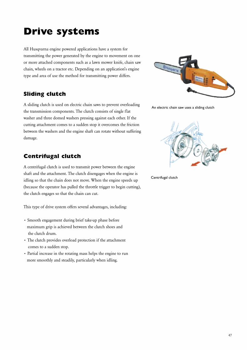
A sliding clutch is used on electric chain saws to prevent overloading the transmission components. The clutch consists of single flat washer and three domed washers pressing against each other. If the cutting attachment comes to a sudden stop it overcomes the friction between the washers and the engine shaft can rotate without suffering damage.
Centrifugal clutch
A centrifugal clutch is used to transmit power between the engine shaft and the attachment. The clutch disengages when the engine is idling so that the chain does not move. When the engine speeds up (because the operator has pulled the throttle trigger to begin cutting), the clutch engages so that the chain can cut. This type of drive system offers several advantages, including:
• Smooth engagement during brief take-up phase before maximum grip is achieved between the clutch shoes and the clutch drum.• The clutch provides overload protection if the attachment comes to a sudden stop.• Partial increase in the rotating mass helps the engine to run more smoothly and steadily, particularly when idling.
An electric chain saw uses a sliding clutch
Centrifugal clutch

48
The centrifugal clutch has centrifugal weights (clutch shoes) that are mounted on a hub so that they are free to slide outwards. The clutch hub is threaded onto the engine drive shaft. There may be two or three clutch shoes, which are held together by springs.
As the speed of the engine increases, the clutch shoes are pushed outwards by centrifugal force. When this is sufficiently high it overcomes the spring force, and the shoes engage the clutch drum and drive it round, and once the drum starts turning, so does the chain. This takes place at an engine speed of around 3600–4600 rpm.
The clutch shoes are manufactured of sintered metal and on some models are fitted with a friction lining. In principle there are two different ways to support the clutch shoes on the hub:
1. One end of the shoe is supported around a pivot pin on the clutch hub. Type 1 is often used on, for example, clearing saws and trimmers that have a relatively low engine output.
2. The shoe may then slide between two guide plates that are either: 2 A is completely straight and run perpendicularly to the centre of the axle. 2 B is curved and angled to the centre of the axle. Type 2 A is used on large clearing saws, small and medium chain saws. Type 2 B is used on large chain saws with a high output. This design also gives a specific servo-effect on the clutch and in doing so increases the pressure against the clutch drum.
Clutch shoe type 1
Drive systems
Clutch shoe type 2A
Clutch shoe type 2B

49
Kickback
In the early sixties, as chain saws were getting lighter and more manageable, the use of chain saws changed from felling trees to also including limbing. This change of use dramatically increased the number of kickback accidents. Kickback is caused when the teeth on the saw chain do not cut into the timber as normal, but jam and start to climb. The upward and backward forces at the tip of the bar result in the chain saw being thrown upwards and backwards at the same time as it turns around its own centre of gravity. This leads to the saw’s guide bar and chain is thrown backwards in a rotational movement towards the logger causing severe injuries on the logger’s face, arms or upper body. Husqvarna looked very seriously at this trend and have taken several safety measures to prevent injuries caused by kickback accidents.
Kickback causes
Chain saws from the sexties completely lacked vibration dampening devices. Vibrations and forces during kickback propagated directly out to the operator’s hands. The forces on the saw’s handle became so great that the operator could no longer hold the saw in position. Another contributing factor to this was the operators did not hold the handle so firmly in order to reduce the unpleasant vibrations.
Kickback solutions
Towards the end of the sixties different solutions started to emerge to prevent the effects of kickback accidents. Initially protection consisted of a fending loop placed in front of the chain saw’s loop handle. In the event of kickback the loop hit the operator’s wrist and the bars upward swing was stopped.
Kickback situation
The teeth of the chainsaw jams
Fending loop
Protective equipment

50
The introduction of vibration dampened chain saws with a separate engine and tank unit have also helped to reduce the number of kickback accidents. Vibration dampening results in the forces generated during kickback being gradually and not instantaneously transferred to the handle section, as a large part of the kickback energy is taken up by the vibration dampening rubber element. The characteristics of the rubber element and its position at the time of kickback are very important.
The forces in the operator’s hands become smaller the heavier the handle section is in relation to the bar and the engine unit, as a specific part of the engine unit’s kinetic energy from the kickback is used to put the heavier handle section in motion. Another contributing cause to the number of accidents falling in connection with the introduction of vibration dampened chain saws was due to the operator being able to hold the handle more firmly without being irritated by the vibrations from the engine.
Chain brake development
The main purpose of the chain brake is to stop the chain as fast as possible in the case of a kickback accident. At the beginning of the 1970’s the first chain brakes were introduced. These acted on the clutch drum via a link system and were released when the operator’s hand contacted the hand guard. Today there are several different types of chain brakes on the market.
In 1971 Jonsered presented the world’s first mass-produced chain brake. A brake-block which was pressed against the clutch drum by a spring, which in its turn was released by a link system, was used.
Brake band
To avoid point loading and bending of the crankshaft, modern saws use a brake band around the clutch drum. Once again this construction uses a pre-tensioned spring to supply the force. The brake band is tightened by a linkage system that is activated when the hand guard is pushed forwards. The brake band principle is used on most modern chainsaws.
Vibration dampened chain saws with a separate engine and tank unit
Chain brake principle
Brake band around the clutch drum
Protective equipment

51
The release impulse for the chain brake previously came from the operator’s hand when it contacted the hand guard. The hand therefore had to be in a certain position on the front handle in order for the chain brake to be released. So that the chain brake can be released in all operating positions, we now have an automatic release system.
Swed-o-Matic
The first automatic release mechanism was named Swed-o-Matic. This system used the slight movement which occurred between the engine and the tank unit at the initiation of kickback. This design was made possible by the introduction of vibration damping using elastic dampers. The engine and chain brake moved upwards during the first hundredths of a second, while because of inertia the tank remains in the original position. This resulted in the release mechanism on the chain brake contacting the handle and the brake being released. Braking took place very quickly and the operator normally did not have time to recognize the kickback before the chain has stopped.
The Swed-o-Matic also helped to reduce the angle of kickback i.e. the angle between the work piece and the saw’s highest position during a kickback. A free moving chain saw without the Swed-o-Matic swings up to 90°, while the kickback angle for a saw with the Swed-o-Matic is only one third of that - about 30°. One contributing factor to the angle of kickback being so small is that the flywheel’s rotation energy helps to subdue it, as it moves in the opposite direction to the upward angle.
The Swed-o-Matic was a big step forward when it came to reducing the number of kickback accidents. The design could be improved further, it could be more operationally dependable and with more reliable adjustments. The next step therefore was to make the brake fully automatic.
Automatic release system
Swed-o-Matic reduced the angle of kickback
Protective equipment

52
Inertia-release chain brake
In 1981 the first inertia-release chain brake was introduced on model 133. The principle was simple. In case of a swift momentary movement (e.g. kickback), a weight attempts to remain in its position. This fact was used for construction of the new brakes which were fitted with a weight placed near the release mechanism. In its method of operation, it can be compared with the trigger mechanism of a gun.
The further development of the inertia-release brake lead to the weight, which was previously placed near the release mechanism, being moved right to the top on the hand guard. By this means it could be made lighter by retained release energy. The strain on the hand guard’s bearing was reduced, which resulted in a longer working life. The release mechanism was shaped like a knee. The release time for the chain brake is currently the same as when the first chain brake was introduced.
Right hand guard
To protect the loggers’ right hand, the lower part of the rear handle has been widened with a streamlined design. In this way injuries to the right hand are prevented, especially when the chain breaks, but also during limbing work when the hand can easily come into contact with branches. The underside of the handle is completely smooth so that the chain saw can easily slide along the tree-trunk.
Chain catcher
The chain on the chain saw seldom breaks. If this happens all the same, the chain is effectively stopped by the chain catcher. This is located on the front part of the crankcase under the bar mount.
First inertia-release chain brake was introduced 1981
Release mechanism
Right hand guard
Chain catcher
Protective equipment

53
Throttle lock
The throttle lock has the task of preventing accidents caused by activating the throttle unintentionally. The mechanism is designed so that the throttle cannot be moved if the hand does not have a firm grip around the rear handle.
Guard, safety stop
A blade on a power cutter rotates at a periphery speed of 80 – 100 m/s (262-328 f/s). At these high speeds a large number of personal injuries can occur if the blade for some reason should become damaged. For this reason a solid guard is fitted over the blade and loose, flying objects can be caught. A safety pin is placed in the cutting arm to prevent the guard from rotating with the blade during a failure. The pin enters a countersink in the guard and limits its movement.
The arrow shows the safety pin
Throttle lock
Protective equipment

54

55
Personal protective equipmentProtective clothing should be in highly visible colours. Protective equipment must be tested in accordance with applicable EU directives and standards (CE approved). Countries outside the EU may require tests in accordance with other national standards. These requirements may vary between different countries. More information is available from your Husqvarna servicing dealer.
Helmet with hearing protector and visor
The helmet is designed to protect you from falling branches and impact. The visor should cover your entire face in order to protect against scrapes and flying chips and saw dust. Hearing protection guards against harmful loud noises. The inserts in the hearing protector become worn out with time. It is important that you replace them on a regular basis.
Jacket
The jacket should be full coverage, ventilated and in highly visible colours.
Protective trousers
The protective trousers should be fitted with saw protection that satisfies the EU directive (CE approved) or other national directives. The trousers should be discarded if the protective layers have been damaged by a saw. The textile fibres in the protective trousers are designed to stop the motion of the chain.
Helmet with hearing protector and visor
Jacket
Protective trousers
The textile fibres in the protective trousers are designed to stop the motion of the chain.

56
Personal protective equipment
Protective boots
Boots and ankle boots should be equipped with protective toecaps, saw protection and non-slip soles in accordance with the EU directive (CE approved) or other national directives.
Protective gloves
Protective gloves should always be worn for protection against cuts and scrapes, oils and fuel.
First aid kit
You should always have a first aid kit available and accessible. A first aid box must always be on-site in the felling area. Gloves with saw protection on the left glove also protect you against the saw chain.
Communication in event of accident
In the event of an accident, you must be able to call for help quickly. Always have a whistle and a mobile phone/communication radio at the felling site.
For your own sake, never omit any part of the protective equipment!
Protective boots
Protective gloves
First aid kit

57
Vibration damping did not appear on hand-held machines until the mid-sixties. By then machines were becoming increasingly lighter, which meant that vibration became more noticeable to the user since the damping mass of the machines was reduced.
Occupational injury white fingers
As chainsaws became lighter the vibration from the saw was more and more absorbed by the person holding the saw instead of the saw itself. This led to a dramatic increase of vibration injuries. It was soon concluded that the vibration from chainsaws was directly related to the so-called white fingers injury. This is an injury where the chain saw operator’s fingers turn white due to poor blood circulation. This leads to a sensation of numbness in the hands and arms.
Husqvarna’s LowVib system
Husqvarna’s chain saws are developed to insulate the handlebars from the engine. The engine’s moving parts are produced of low weight material that results in minimal gyro forces, which also decreases the saw’s vibration. Husqvarna’s two-mass, anti-vibration construction uses springs or rubber to separate the engine from the handles, a system called LowVib. The user’s hands and arms experience significantly reduced vibrations from the engine, bar or chain.
Ergonomics
Occupational injury white fingers
LowVib system - Engine unit and handle unit isolated from each other by vibration dampers

58
Husqvarna LowVib chain
As of the introduction of model 394 XP in 1992, the traditional rubber dampers have been replaced in favour of springs. Through careful testing of the placing of the four springs, not only were lower vibration values obtained, but also a longer working life. The rubber dampers are inclined to be affected by petrol and oil, which results in varied vibration damping and a shorter working life.
Reciprocating counterweights
Several engine manufacturers have succeeded in reducing engine vibration by using rotating or reciprocating counterweights. The principle is to make the counterweight move in the opposite direction to the piston so that the reciprocating forces are cancelled out.
Chain vibration
During development work on damping engine vibration, Husqvarna’s technicians also turned their attention towards the chain and how this generates vibrations during cutting. A traditional chain has a relatively large contact surface against the bar. Each time a cutting link cuts wood, it hammers against the bar. The resulting vibrations vary in intensity, depending on the type of wood and if the timber is frozen or not.
Husqvarna LowVib chain
In order to reduce the cutting link’s hammering against the bar, a new link with a new profile and a smaller bar contact surface was constructed. The shape of the new cutting link causes the power which arises when the link meets the wood to be directed into the length of the chain instead of going down into the bar. With this type of chain, which has been named the Husqvarna LowVib, chain vibration during sawing in soft wood has been reduced by up to 30%.
Traditional chain has a relatively large contact surface against the bar causing vibrations
Ergonomics
LowVib chain

59
Husqvarna E-TECH
In 1996 Husqvarna presented a new, improved two-stroke engine as a part of the company’s efforts to produce engines that emit smaller amounts of hazardous substances. The new engine was given the designation E-TECH and was first used in new trimmer and brush cutter models. More stringent environment regulations in the USA, which primarily involve a lowering of the hydrocarbons, nitrous oxides and carbon monoxide content, brought about the new engine design. Environment degradation is reduced through decreasing the amount of unburned gases (flushing losses) in the exhaust fumes. Comparison between an E-TECH engine model and the three year older engine design model 125 show that the CO content has been halved and the hydrocarbons and nitrous oxide contents have been reduced by close to 70%. In addition a powerful increase in output is gained.
A = Air consisting of: 21% oxygen, 78% nitrogen, 1% othersB = Fuel consisting of: hydrocarbons (petrol), two-stroke oil (2%)C = Exhaust fumes consisting of: hydrocarbons (HC), nitrogen oxides (NOx), carbon monoxide (CO), carbon dioxide (CO2), particles (PM)D = Fuel-air mixture consisting of: 92% air, 8% petrol
Catalytic exhaust emission control
A catalytic converter has the task of facilitating chemical reactions between other substances without actually taking part in the process. This fact is utilised for example to clean exhaust fumes from combustion engines. The engine’s fuel consists primarily of carbon and hydrogen, which is mixed with air in the carburettor. The intake air consists to 1/5 of oxygen (O2) and 4/5 nitrogen (N2). The nitrogen does not normally take part in the combustion, but goes straight through the engine without being affected. The oxygen is mainly used in the engine’s combustion process. Only a small part remains for afterburning in the catalytic converter. Nitrogen oxides (NOx) are formed with the combustion of nitrogen at very high pressures and temperatures. When the combustion is incomplete (deficit of oxygen) poisonous carbon monoxide (CO) is formed. With the right amount of oxygen, carbon dioxide (CO2) is formed, which is not poisonous.
Muffler with catalytic converter
E-TECH engine
Environment

60
When exhaust emission control demands are discussed it is primarily carbon monoxide, hydrocarbons and nitrogen oxide that are included. The catalytic converter has been designed to reduce the amounts of these substances in the exhaust fumes. In this carbon monoxide and hydrocarbons are combusted into carbon dioxide and water. The amount of carbon dioxide can not be affected in any other way than by lowering fuel consumption or the use of fuel with a lower carbon content. Nitrogen does not normally affect the catalytic converter’s combustion process. The oxygen that remains after combustion in the engine is consumed in the catalytic converter.
Environmental Provisions
In tandem with the impaired environment and the increase in environmental awareness (not least on account of the sorting of waste in many countries) environmental provisions on a number of fronts have come about. California has been a forerunner when it concerns legislation regarding exhaust emissions from combustion engines.
CARB 1
CARB is an abbreviation for California Air Resources Board, which is an agency that has established the regulations which prescribe that the discharge of hydrocarbons shall be reduced by 30%. In addition, limit values have been stated for nitrogen oxides (NOx) and carbon dioxide (CO2). These regulations only apply in California from August 1, 1995 but do not apply to chain saws above 45 cm3 and clearing saws above 40 cm3.
EPA 1
EPA is an abbreviation for the Environmental Protection Agency. These regulations regulate exhaust emissions from combustion engines smaller than 25 hp and came into force on January 1, 1998. In principle the regulations involve the same limitations as in CARB 1.
Catalytic converter
Environment

61
EU 1
All products placed on the EU market after February 11, 2005 must fulfil the EU 1 exhaust requirements, which correspond to EPA 1.
CARB 2
From January 1, 2000 the CARB 1 regulations have been tightened yet further. New to these regulations is that limitations have also been introduced for the particle content (PM) in exhaust fumes. In addition, the amounts of HC and NOx have been combined into one limit value and at the same time been reduced significantly. The limits apply to the average level of the product range from a manufacturer. EPA is expected to follow suit with its regulations by introducing a second stage.
EPA 2
Beginning January 1, 2002 EPA has introduced a phase-in programme for below 50 cc engines to reach much stricter emission limits by 1 January, 2005. The limits apply to the manufacturer’s product range average. The same applies for engines above 50 cc, but with the phase-in period delayed by 2 years, i.e. 2004-2007. Engine families below 5000 units per year may remain certified according to EPA 1 three years after the last phase-in year, i.e. until end of 2007 and 2009 respectively.
EU 2
New tighter limits according to EPA 2 will be introduced in the EU starting in August 2007 for certain products below 50cc. By August 2011 virtually all products must fulfil the EU 2 requirements.
CARB 3
From January 1, 2005, CARB is expected to further reduce the HC+NOx exhaust limits, which means harmonisation with the EPA. From 2007 CARB is expected to introduce regulations for fuel tank permeation and, for non-handheld products, also evaporation.
Environment
The regulations above will continue until new come into force
The regulations above will continue until new come into force
The regulations above will continue until new come into force

www.husqvarna.com
Copyright © 2011 Husqvarna AB (publ.) All rights reserved. Husqvarna is a registered trademark of Husqvarna AB (publ.)
115
01 4
9-26
G
B
2011
-05