2006 ASME Rayleigh Lecture The Cost of Silencefiles.asme.org/Divisions/NCAD/16128.pdf · 2006 ASME...
77
2006 ASME Rayleigh Lecture The Cost of Silence Donald E. Thompson Alion Science and Technology Mystic, Connecticut
Transcript of 2006 ASME Rayleigh Lecture The Cost of Silencefiles.asme.org/Divisions/NCAD/16128.pdf · 2006 ASME...

2006 ASME Rayleigh Lecture
The Cost of Silence
Donald E. ThompsonAlion Science and Technology
Mystic, Connecticut

6/20/2007
Slide 2
Introduction
• Cost has Always been a Major Driver in the Commercial World• Cost has Become a Major Driver in Military Applications
• Advanced Propulsion Systems Symposium – American Society of Naval Engineers
• Acoustic Requirements Can be a Major Cost Driver• Implementation of Acoustic Mitigation Methods for a System
Component Does Affect Other Components in the System• Acoustic Design and Optimization of a Component Must Occur
in Context of a Systems Approach• Concept and Mitigation Method Innovation Required

6/20/2007
Slide 3
Scope of Presentation
• System Design and Optimization• Focusing on System Approach
• Innovative Concepts• A Select Few
• Innovative Components / Methods• A Select Few

6/20/2007
Slide 4
System Design and Optimization

6/20/2007
Slide 5
Overall Objective
• Reduce Cost by Improving Design Process• Especially at the Early Stages of Assessment of Alternatives
(AOA) and Preliminary Design
• Reduce Cost by Rapid Response to Requirements / Mission Changes
• Eliminate Stovepipes in Design Community• Reduce Cost by Rapid Solution of Design Mods Due to
Test Feedback
Vibration and Radiated Noise are a Very Important Considerationfor Both Commercial and Military Applications

6/20/2007
Slide 6
Design Space Exploration
Index of Attention and
Influence
Manufac
turin
g
Ramp-U
p
Source:"Leading Product Development”Wheelwright & ClarkHarvard Business School
Low
Phases
Knowledge
Acquisi
tion
Concept
Investi
gatio
n
Basic D
esign
Proto
type
Building Pilo
t
Producti
on
ABILITYTO INFLUENCEOUTCOME
High
ACTUAL MANAGEMENT ACTIVITY PROFILE
Design Space
Exploration
Owner
TOC/ROI
TLR

6/20/2007
Slide 7
Rational Unified ProcessApplied to FlagShip Designer Development
Each phase is broken into multiple iterations
Development PhasesW
orkf
low
s Requirements

6/20/2007
Slide 8
Overall Approach
• Consider All Systems in an Integrated / Interactive Manner• For Each System, Employ State-of-the-Art Design / Performance
Tools• AOA• Preliminary Design• Final Design
• Link the Tools with a Robust Framework• Allows Rapid Data Exchange• System and Subsystem Toolboxes Easily Exchangeable• Expandable
• Employ Optimizer• Several Approaches Available

6/20/2007
Slide 9
AOA, Preliminary Design, and Final Design
AOA• Define Best Combination of Systems to Perform Specified Mission(s) with Given
Constraints and Goals• Simple, Fast, but Accurate• Numerous Iterations• Tradeoff System Concepts• Determine Gross Characteristics (size, arrangements, speed, etc.)• Downselect
Preliminary Design• Tune Subsystem Characteristics
• Higher-fidelity Tools• Limited Iterations
Final Design• Define Subsystem and System Details
• Predict Final Performance• Precise Tools• No Iterations (hopefully)
Cost is a Big Driver

6/20/2007
Slide 10
Typical Systems (unmanned underwater vehicle)
• Guidance and Control• Energy• Payload• Navigation• Propulsion• Communication• Shell
6/20/2007
Slide 11
Propulsion Subsystems
• Prime Mover• Gears (?)• Shaft• Propeller
6/20/2007
Slide 12
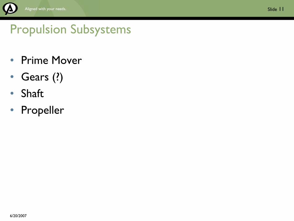
Framework
Mission Goals
Constraints Weighting
Prime Mover Module
Acoustics Electromagnetics
Efficiency
Propulsor Module
Acoustics Hydrodynamics
Structures Maneuvering
Shell Module
Acoustics Maneuvering
Structures Hydrodynamics
Propulsion Module
Other System Modules Other System Modules

6/20/2007
Slide 13
Several Approaches are Being Developed
Consider Two of Those Approaches as Examples• Synthesis of Naval Architecture Concepts (SNARC)
• Being Developed by NUWCDIVNPT• Part of Multidisciplinary Design Optimization (MSDO) Program• Sponsored by K. Ng, ONR 332• Focused on Weapons and UUVs
• FlagShip Designer• Developed but Being Expanded by Proteus Division, Alion Science and
Technology• Legacy Code Developed with Internal Funds (commercial applications)• Expansions Sponsored by NAVSEA and ONR (military applications)

6/20/2007
Slide 14
MSDO
• Objective• Develop Capabilities for Design Analyses, Evaluation, and Optimization• Reduce Total Ownership Cost
• Approach• Implement and Integrate Computational and Design Tools• Develop Distributed Design and Virtual Environment for Prototyping• Incorporate Silencing and Propulsion Efforts
• Payoff• Design Infrastructure, Analysis Tools, and Concepts That Support
Affordable Undersea Weapons

6/20/2007
Slide 15
MSDO (Cont’d)
• Major Performers• NUWCDIVNPT• ARL / PSU• NSWC-CD• NSWC-IH• SAIC• Alion Science and Technology• CDI• Barber-Nichols• Fuel Cell Energy• University of Maryland• Georgia Tech• Wright State University• MIT• University of Vermont

6/20/2007
Slide 16
MSDO Impact / Metrics
• Quantify Cost Effectiveness• Support Affordable Undersea Weapon Acquisition
• 30% Reduction in Development Time• 50% Reduction in Total Ownership Cost• 80% Reduction in Paper Process
6/20/2007
Slide 17
SNARCNUWCDIVNPT
Reference2006 ONR Supercavitating Torpedoand Multidisciplinary Systems Design
and Optimization Workshop
20–22 June 2006Whispering Pines Conference Center
West Greenwich, Rhode Island

6/20/2007
Slide 18

6/20/2007
Slide 19
6/20/2007
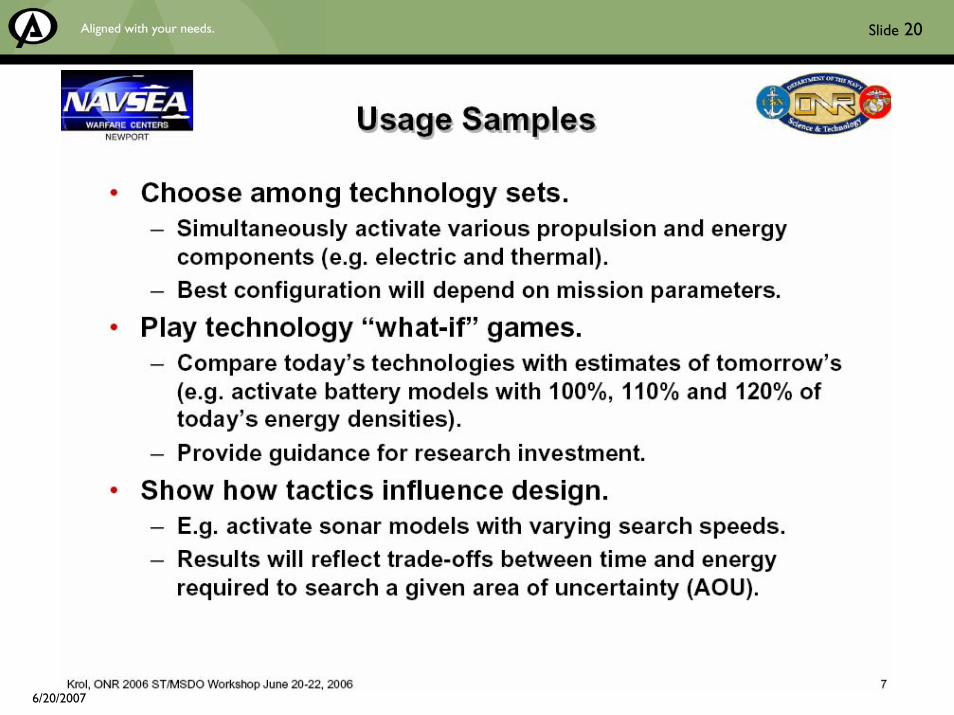
Slide 20

6/20/2007
Slide 21

6/20/2007
Slide 22

6/20/2007
Slide 23

6/20/2007
Slide 24
FlagShip Designer
ProteusAlion Science and Technology

6/20/2007
Slide 25
FlagShip Designer Smart Product Model Vision• A Legacy Commercial Code for Surface Ship Naval Architecture
Design• Optimization Capabilities Currently Being Included
• An Extensible and Scalable Framework in Which to Integrate Naval Architecture and Related Disciplines
• A Smart Product Model (SPM) Implementation Within the Larger Context of an Integrated Data Environment (IDE)• Integration with the U.S. Navy’s LEAPS
• Open Architecture to Allow Users to Extend Designer with Their Own Applications and Components• Allow and Encourage Third-party Components by Providing a well-defined
API• Focus on Early-stage Design and Analysis
• Bias Architecture and Implementation Toward Engineering Performance Rather than Toward High Levels of Concurrency
• Cost Component Included

6/20/2007
Slide 26
Design Integration Through FlagShip Designer
• FlagShip Designer Provides a Computer-based “Toolset” to Accurately, Simultaneously, and Efficiently Explore the Full Range of:• Mission Requirements• Design Options• Candidate Technologies
MissionRequirements
Acquisitionand TotalOwnership
Cost
ProgramManagement
Advanced,First-Principles
Design
• Enables effective Design Space exploration using first principles
• Generates real-time, accurate cost estimates
• Shortens design/cost iteration cycle time
• Improves design/cost iteration accuracy
• Implements design spiral process evolving from concept through preliminary, contract, and detail design phases

6/20/2007
Slide 27
FlagShip Designer’s Advanced Engineering Infrastructure Enables Multidisciplinary Optimization
Tier ASystem-level and Mission Based
Analysis Tools Integration
Tier BFlagShip Designer Framework
Tier CSystems Engineering
Optimization Technology
Existing FlagShip Designer Components

6/20/2007
Slide 28
Design Integration Through FlagShip Designer
~~~~~~
~~~~~~
FlagShip DesignerConceptual Modeling & Integrated Design
CostEstimating
GeneralArrangements
Non-StructuralSystems Craft Concept Engineering
Applications
Resistance & Powering
Discipline-Specific Supporting Tools
Weight Estimating& Tracking
Hullform Design& Fairing
Signatures
Maneuvering
Hydrostatics & Stability
Seakeeping
Structural Design& Analysis
Acoustics

6/20/2007
Slide 29
Acoustics in Commercial World
• Cruise Ships – Habitability• Machinery Vibration• Propulsor-induced Aft Hull Vibration
• General• Fatigue Due to Vibration• Cavitation Damage – Propellers, Rudders, et al.

6/20/2007
Slide 30
Acoustic Implications of Cost-driven Design and Optimization• Viable Tools for AOA-level Studies – Near Term
• Robust• Fast, Inexpensive to Implement and Execute• Verification, Validation
• Integrated with Other Performance Areas at the Component Level, i.e., for a Propulsor• Hydrodynamics• Shock / Structures• Materials
• Integrated at the System Level, i.e., for a Propulsion System• Hull• Shafting• Prime Mover
• Integrated at the System-of-Systems Level, i.e., the Entire Vehicle

6/20/2007
Slide 31
Innovative Concepts

6/20/2007
Slide 32
Advanced Podded Propulsor ConceptsCommercial Cruise Ships

6/20/2007
Slide 33
Typical Podded PropulsorsMounted on a Commercial Cruise Ship

6/20/2007
Slide 34
Features Compared to Internal Motor with Shaft
• Motor, Shaft, Bearings, etc., in Hub External to Hull• Eliminates External Shaft and Strut Drag and Wakes• Eliminates Shaft, Bearings in Hull
• Pods Azimuth for Thrust Vectoring• Eliminates Rudder and Ancillaries• Better Low Speed Control• Allows Docking without Tugs• Improved Backing Performance
• Location and Type of Propulsor Flexible• Tractor (Puller)• Pusher• Single vs. Co-rotating vs. Counter-rotating Propellers

6/20/2007
Slide 35
Why Pods?• Reduced Construction Time / Cost
• Pod and Hull Independently / Simultaneously Fabricated
• Hull Internal Arrangement• Moving Motor and Shaft to Pod Allows More Cabins Aft
• Improved Efficiency Reduces Operating Costs• Higher Speeds Possible; Therefore, More Trips Possible• Easier, Faster Repair• Improved Cavitation Performance; Therefore, Less
Damage• Reduced Hull Vibration; Therefore, Less Fatigue
Pods are Cost Effective

6/20/2007
Slide 36
Pod Issues
• Initial Issues with Bearings, Seals, and Stress Cracks Have Apparently Been Solved
• Weight Aft : Ship Balance OK• Propeller / Support Strut Interaction : Cavitation and
Vibration Affected
Pods are Cost Effective

6/20/2007
Slide 37
Next Generation Podsfor Commercial Cruise Ships?

6/20/2007
Slide 38
EB Rim Drive Pods for Commercial Cruise Ships
References
1. Van Blarcom, Bill, et al., “The Commercial Rim-Driven Permanent Magnet Motor Propulsor Pod,”ShipTech 2003 Proceedings, Biloxi, MS, January 2003.
2. Lea, M., et al., “Scale Model Testing of a Commercial Rim-Driven Propulsor Pod,” SNAME J Ship Production, Vol. 19, No. 2, May 2003.

6/20/2007
Slide 39
Features Compared to Existing Pods
• Integrated Motor and Propulsor• Permanent Magnet Motor• Ducted Propulsor• Motor Stator Integral Part of Duct• Motor Rotor on Rim Attached to Rotating Blade Tips• Stationary Blades Remove Flow Swirl and Provide
Structural Support
• Pods Azimuth

6/20/2007
Slide 40
Why Rim Drive Pods?
• Gain All Benefits of Existing Pods with Further Improvements in:• Efficiency• Speed• Cavitation (ahead and in turns)• Hull Vibration
• Eliminates Motor Cooling Requirements• Smaller
• Diameter About the Same as Existing Propeller• Much Shorter
• Reduced Weight• No Propeller / Strut Interaction• Hydrodynamic Benefits of Duct• Duct Shielding of Rotor / Hull Unsteady Pressures

6/20/2007
Slide 41
Typical ~20MW Commercial Pod vs. ~18.5MWCRDPShown in Relative Size (CRDP ~1/3 length)
Typical Twin-Screw Panamax Cruise Ship –Hub-Drive Pod vs. CRDP Arrangement Comparison

6/20/2007
Slide 42
Behind Hull Powering Results,CRDP vs. Good Representative Hub-Drive Pod
CRDP Operating for 26 Knots at 0°
CRDP Operating for 26 Knots at 8°
Hull Unsteady Pressures(at least 1/5 the levels of existing pods)

6/20/2007
Slide 43
Flexible Composite Propeller
AIR Fertigung-Technologie GmbHHohen Luckow, Germany
1. Internet2. Company Brochures3. Personal Communications

6/20/2007
Slide 44
Objective and Approach
Objective• Provide a Commercial Propeller with Improved
Efficiency and Cavitation, Thereby Reducing Operating Cost and Ship Vibrations
Approach• Employ a Composite Material for the Blades• Exploit the Tailorability of Composite Materials• Design the Blades to Flex, so That They Operate on or
Closer to Design
Straightforward, Simple Idea

6/20/2007
Slide 45
Design Strategy
• A Surface Ship Propeller Typically Operates in a Non-uniform Flow Field due to:• Shaft Angle Circumferential Velocity Non-uniformities• Partial Ingestion of Hull Boundary Layer Axial Velocity Non-uniformities
• Due to Surface Ship Hull vs. Wave Drag, Propeller Operating Point is not Constant• Standard Metal Propeller Design Approach
• Design to Spatially Averaged Inflow Field• At the Ship Speed Having Most Resident Time
• As Blades Operate in the Non-uniform Flow Fields and at Varying Operating Points, the Blade Angle of Attack Varies, Resulting in Blade Unsteady Pressures (lift)
• Adverse Impact on Cavitation Performance (aft hull vibration)• Adverse Impact on Efficiency (operating cost)
• Flexible Composite Propeller Design Approach• Design to Spatially Averaged Inflow Field at Target Ship Speed• But Design Blades to Bend and Twist due to Varying Lift so That Varying Lift is Mitigated• Average and Varying Lift on Blade is Provided by Hydrodynamic Design• Blade Material Tailoring Used to Provide Required Bend and Twist
• Specifics• Carbon Fiber Composite Material• Blades Fabricated Individually, Then Mounted to Metal Hub

6/20/2007
Slide 46
Sample At-sea Installations
Contur® Carbon Fiber Propellers Fitted on a Mine Hunter of Netherlands Navy
M/Y “Calisto” –The Sister Vessel of Jacques Cousteau's “Calypso” Fitted with Contur®Propellers
M/Y “Red Sapphire” –Dubai During Survey in
Dubai Dry Dock
Contur® is the trade name for AIR’s composite propeller.

6/20/2007
Slide 47
Flexible Composite Propeller BenefitsOther Cost-saving Attributes• If Damaged, Individual Blades can be Replaced
(even underwater)• No Drydocking
• Weight Reduction (25% to 35% of metal propeller)
• Less Stress on Shaft, Bearings, and Stern• Improved Acceleration (on design operation)
• Less Fuel• Reduced Stern Vibration
• Less Fatigue Damage• Fabricated Using High-precision Mold
(“identical blades”)• Less Effort in Balancing
• Corrosion Resistant (material characteristic)• Less Corrosion Protection• No Cleaning, Repair, Replacement
• Anti-fouling Coating• No Paint• No Cleaning
• Impact Resistant (material tailoring)• Less Damage, Repair, Replacement
• Improved Cavitation Performance• Less Cavitation Damage, Repair, Replacement
Benefit of Improved Efficiency (reduced cost)
Per-unit Cost Comparable to Metalbut Depends on Total Number Made
(mold amortizement)
3% to 10% Improvement in Efficiency

6/20/2007
Slide 48
Acoustic Implications of Cost-driven Concepts
• Innovation Required• Completely New Concepts
• Modified or New Acoustic Tools for New Concepts• Acoustic Tools Should be Integrated with Other Design
Tools• Hydrodynamics• Materials• Shock• etc.
• Systems Approach Should be Taken• Design and Optimization Codes Should be Used

6/20/2007
Slide 49
Innovative Components / Methods

6/20/2007
Slide 50
Jonson, M.L.
Sound Power Reduction of Structures with Nearly Degenerate Modes by Material Tailoring
Ph.D. Thesis, Mechanical EngineeringPennsylvania State University
December, 1998
6/20/2007
Slide 51
Scope– Objectives
• Consider the case of a propeller with a central hub surrounded by identical blades
• Understand natural frequencies and mode shapes• Investigate possible radiated noise reduction by
material tailoring
– Approach• Develop a simple analytical model of propeller for
first set of modes.• Confirm with computational and experimental
studies.

6/20/2007
Slide 52
Computational Configurations
• To verify radiated sound power reduction observed from analytical study, an existing five-bladed propeller will be analyzed
– In-vacuo with no trim masses (no sound power)
– In water with no trim masses– In water with even trim masses– In water with uneven trim masses

6/20/2007
Slide 53
EvenTrim Masses
> 4.00e+01< 4.00e+01< 3.33e+01< 2.00e+01< 1.33e+01< 6.67e+00< 00e+00

6/20/2007
Slide 54
UnevenTrim Masses
> 4.00e+01< 4.00e+01< 3.33e+01< 2.00e+01< 1.33e+01< 6.67e+00< 00e+00

6/20/2007
Slide 55
Admittance for Uniform Mass Loading
•All blades respond identically.•Resonance frequencies scale as inversely as mass loading
102 1032 3 4 5 6 7 8 9
Frequency (Hz)
-110-100
-90-80-70-60-50-40-30-20
Adm
ittan
ce A
mpl
itude
(dB
re 1
m/s
*N)
In-vacuo, No trim massesIn Water, No Trim MassesIn water, Even Trim Masses
102 1032 3 4 5 6 7 8 9
Frequency (Hz)
0
90
180
270
360A
dmitt
ance
Pha
se

6/20/2007
Slide 56
Admittance for Non-Uniform Trim-Mass Loading
•Response of every blade is different. •Phases of different bladescan be 180 degrees out of phase.
102 1032 3 4 5 6 7 8 9
Frequency (Hz)
-110-100-90-80-70-60-50-40-30-20
Admi
ttanc
e Amp
litud
e (dB
re 1m
/s*N)
Blade 1Blade 2Blade 3Blade 4Blade 5
102 1032 3 4 5 6 7 8 9
Frequency (Hz)
0
90
180
270
360
Admi
ttanc
e Pha
se
Blade 1Blade 2Blade 3Blade 4Blade 5

6/20/2007
Slide 57
Effect of Mass Loading on Radiated Power
0 100 200 300 400 500 600 700 800 900 1000
Frequency (Hz)
70
80
90
100
110
Radi
ated
Pow
er d
B re
1pW
No Trim MassesEven Trim MassesUneven Trim MassesSignificant
Reduction for Uneven Trim-Mass Distribution
6/20/2007
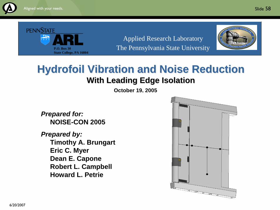
Slide 58
Prepared for:NOISE-CON 2005
Prepared by:Timothy A. BrungartEric C. MyerDean E. CaponeRobert L. CampbellHoward L. Petrie
Hydrofoil Vibration and Noise ReductionHydrofoil Vibration and Noise ReductionWith Leading Edge IsolationWith Leading Edge Isolation
Applied Research LaboratoryThe Pennsylvania State UniversityP.O. Box 30
State College, PA 16804
October 19, 2005

6/20/2007
Slide 59
Introduction
Basic Physics – Unsteady Lift
• Foil unsteady lift dominated by pressure differential in leading edge vicinity- Expression for pressure jump given by Sears and others
*1
*1
11
xx
+−
*1x
0
3
6
9
12
15
-1 -0.5 0 0.5 1
)()(11
2),( *1
*1*
1
*1
0*1
*1 kSkv
xx
Ukxp+−
=′Δ ∞ρ
L.E.

6/20/2007
Slide 60
Introduction
Opportunity for Noise Control
• Reduction of 7 dB by eliminating unsteady lift contribution of initial 20% chord
• Noise control can be achieved by inhibiting transmission of L.E. unsteady lift to remainder of foil- Incorporate vibration isolation mount into foil *
1*1
*1
1
1
*1
*1
*1
1
),(
),(~/)(~
dxkxp
dxkxpLL Total
∫
∫
−
−
′Δ
′Δ=
ξ
ξ
0.0
10.0
20.0
30.0
40.0
50.0
60.0
70.0
80.0
0.0 20.0 40.0 60.0 80.0 100.0
1002
1 xξ+
⎥⎦
⎤⎢⎣
⎡−
TotalLL~
)(~1log20 ξ
(Percent Chord)
7 dB

6/20/2007
Slide 61
Experimental Set-up
A1 A2A3
A4
A5
TrailingEdge
Elliptical Leading Edge
Ground BoltFairings
Bottom “Arm”
Top “Arm”
Gap
Elastomer
Elastomer
A1 A2A3
A4
A5
TrailingEdge
Elliptical Leading Edge
Ground BoltFairings
Bottom “Arm”
Top “Arm”
Gap
Elastomer
Elastomer
A1 A2A3
A4
A5
TrailingEdge
Elliptical Leading Edge
Ground BoltFairings
Bottom “Arm”
Top “Arm”
Gap
Elastomer
Elastomer
• Designed, fabricated and tested mock-up stator with isolated L.E.- Layer of elastomer at 20% chord
- Acts as single stage vibration isolation mount
• Instrumented with 5 accels.- A1 through A5
Prototype Quiet Stator Vane

6/20/2007
Slide 62
N USMC/MEWSS PIP N i C t l/TAB
Experimental Set-up
• Prototype vane at zero angle of incidence on center-line of 305 mm W.T. test section
• Prototype vane isolated from tunnel with “boot” assemblies- Recessed cavities 25 mm deep and lined with soft elastomer
- Arms fit into cavities and edge of isolated L. E. fits flush with tunnel walls
• Prototype vane 50 mm downstream from wake generator- 17% wake generator chord
Prototype Quiet Stator Vane in W.T. Facility
Upper “boot” assembly
Prototype vane
Wake generator

6/20/2007
Slide 63
Results
Surface Averaged Vibration Levels – Isolated Portion of Vane
• Isolated steel L.E. reduces vibration levels 5 to 10 dB at frequencies above 45 Hz
• Isolated L.E. with increased density expected to reduce vibration levels approx.10 to 20 dB at frequencies above 30 Hz- Lumped parameter pred.- Resonance shifted to 24 Hz
• All comp. attached to isolated portion of vane expected to be excited with up to 20 dB less force using vane with more dense isolated L. E.- Reduce vibration of components that cause discomfort and radiate noise
0 20 40 60 80 100 120 140-70
-60
-50
-40
-30
-20
-10
Frequency (Hz)
Vibr
atio
n Sp
ectr
um L
evel
(dB
re 1
m /
s2 p
er H
z)
Measured Steel Rigid
Measured Steel Isolated
Estimated Tungsten Isolated
Acc
el. S
pect
rum
Lev
el (d
B re
1 m
/s2
in 1
Hz
Ban
ds)
10 dB

6/20/2007
Slide 64
Quackenbush, T.R., B.F. Carpenter, and S. Gowing
Design and Testing of a Variable Geometry Ducted Propulsor Using Shape Memory Alloy Actuation
49th Aerospace Sciences MeetingReno, NevadaJanuary, 2005

6/20/2007
Slide 65
Objective, Approach, and Payoff
Objective• Develop and Demonstrate a Thrust Vectoring Ducted PropulsorApproach• Employ Shape Memory Alloy (SMA) Technology on Aft Portion of Duct to Direct
Propulsor Exhaust Flow• Design Model Scale Demonstrator
• Hydrodynamics of Distorted Duct and Effect on Propulsive Performance• Shape Memory Alloy and Actuation Sufficient to Provide Desired Duct Deformation
• Fabricate and Test Model• NSWC-CD 36-inch Water Tunnel
Payoff• Assuming Less Expensive SMAs due to Maturation and Large Orders, Potentially Less
Expensive Than Rudders or Azimuthing• Supports All-electric Approach• Enhanced Low-speed Control• Improved Cavitation Performance (no rudder cavitation)• Eliminates Rudder Actuation Noise• Reduced Weight

6/20/2007
Slide 66
Side View of a Notional Smart Duct Propulsor, Showing the Undeflected (top) and Deflected (bottom) Duct Shape. Propeller Wake is Indicated by the System of Vortex Filaments Trailing from the Ducted Propeller (not shown).

6/20/2007
Slide 67
Representative Snapshots of In-water Testingof the 30-cm-diameter Smart Duct Model(without trailing edge fairing and sheathing)

6/20/2007
Slide 68
Side View (left) of Installed Propeller + Duct Combination; Top / Oblique View of Propeller in Duct with Deformable Sections at 0.75-inch Deflection (right)

6/20/2007
Slide 69
Non-dimensional Side Force vs. Duct Deflectionat 2.5-fps Tunnel Speed and 867 RPM
Side Force Coefficients Measured as a Function of Deflectionfor Three RPM Levels with a Tunnel Speed of 14 fps
Demonstration of High Authority Control Successful

6/20/2007
Slide 70
Rogers, E.O. and J. Abramson
Selected Topics Related to Operational Applications of Circulation Control
Circulation Control WorkshopNSWC-CD, Bethesda, Maryland
March, 2004

6/20/2007
Slide 71
Objectives
• Consider Various Potential Applications of Circulation Control and Prediction Capabilities for Thrust Vectoring• Ducted Propulsor Case Considered Here
• Approach• Use 3-D Inviscid Panel Methods for Design and Performance Predictions• Circulation Control Modeled by Relocating Shed Wake• Test at Small Scale
• Payoff• Potentially Less Expensive Than Rudders or Azimuthing• Supports All-electric Approach• Enhanced Low-speed Control• Improved Cavitation Performance (no rudder cavitation)• Eliminates Rudder Actuation Noise• Reduced Weight

6/20/2007
Slide 72

6/20/2007
Slide 73

6/20/2007
Slide 74

6/20/2007
Slide 75
Results Summary
• Concept Viability Demonstrated at Fundamental Level• Further Model Scale Work Required (with rotor in duct)
• Practical Issues Need to be Addressed• Marine Growth• Corrosion
• Initial Computational Approach Verified• Must Continue with Rotor in Duct

6/20/2007
Slide 76
Acoustic Implications of Cost-driven Innovative Components / Methods• Modified or New Acoustic Tools for New
Components / Methods• Acoustic Tools Should be Integrated with Other Design
Tools• Systems Approach Should be Taken• Design and Optimization Codes Should be Used

6/20/2007
Slide 77
Final Summary
• Cost has Become and Will Continue to be a Major Driver in Acoustic Design
• Acoustic Design Needs to Focus More on Cost Reduction• While Maintaining or Improving Performance
• Several Approaches to Help with Cost Reduction have been Discussed• System Design and Optimization• Innovative Concepts• Innovative Components / Methods
• Others Must be Considered• Impact of Acoustic Design on Fabrication Costs• Reduce Model Scale Testing Using Improved / Verified Preliminary and
Final Design Tools