2006 Academic Challenge - Illinois Academic Challenge ENGINEERING GRAPHICS ... E. auxiliary view...
12
2006 Academic Challenge ENGINEERING GRAPHICS TEST - STATE FINALS – This Test Consists of 50 Questions – Engineering Graphics Test Production Team Ryan Brown, Illinois State University – Author/Team Coordinator Kevin Devine, Illinois State University – Author Jacob Borgerson, University of Illinois at Urbana - Champaign – Reviewer Don Wayman, WYSE – Coordinator of Test Production GENERAL DIRECTIONS Please read the following instructions carefully. This is a timed test; any instructions from the test supervisor should be followed promptly. The test supervisor will give instructions for filling in any necessary information on the answer sheet. Be sure you understand and correctly follow these instructions. You are to indicate your answer to each question by marking an oval that corresponds to the correct answer for that question. Only one oval should be marked to answer each question. Multiple ovals will automatically be graded as an incorrect answer. Be sure ovals are marked as . Not as , , etc. , If you wish to change an answer, erase your first mark completely before marking your new choice. You are advised to use your time effectively and to work as rapidly as you can without losing accuracy. Do not waste your time on questions that are too difficult for you. Go on to the other questions and come back to the difficult ones later if you can. *** TIME: 40 MINUTES *** DO NOT OPEN TEST BOOKLET UNTIL YOU ARE TOLD TO DO SO! © 2006 Worldwide Youth in Science and Engineering “WYSE”, “Worldwide Youth in Science and Engineering” and the “WYSE Design” are service marks of and this work is Copyright © 2006 Board of Trustees of the University of Illinois at Urbana - Champaign. All rights reserved.
Transcript of 2006 Academic Challenge - Illinois Academic Challenge ENGINEERING GRAPHICS ... E. auxiliary view...
2006 Academic Challenge
ENGINEERING GRAPHICS TEST - STATE FINALS
– This Test Consists of 50 Questions –
Engineering Graphics Test Production Team
Ryan Brown, Illinois State University – Author/Team Coordinator Kevin Devine, Illinois State University – Author
Jacob Borgerson, University of Illinois at Urbana - Champaign – Reviewer Don Wayman, WYSE – Coordinator of Test Production
GENERAL DIRECTIONS Please read the following instructions carefully. This is a timed test; any instructions from the test supervisor should be followed promptly. The test supervisor will give instructions for filling in any necessary information on the answer sheet. Be sure you understand and correctly follow these instructions. You are to indicate your answer to each question by marking an oval that corresponds to the correct answer for that question. Only one oval should be marked to answer each question. Multiple ovals will automatically be graded as an incorrect answer. Be sure ovals are marked as . Not as , , etc.
, If you wish to change an answer, erase your first mark completely before marking your new choice. You are advised to use your time effectively and to work as rapidly as you can without losing accuracy. Do not waste your time on questions that are too difficult for you. Go on to the other questions and come back to the difficult ones later if you can.
*** TIME: 40 MINUTES ***
DO NOT OPEN TEST BOOKLET UNTIL YOU ARE TOLD TO DO SO!
© 2006 Worldwide Youth in Science and Engineering “WYSE”, “Worldwide Youth in Science and Engineering” and the “WYSE Design” are service marks of and this work is
Copyright © 2006 Board of Trustees of the University of Illinois at Urbana - Champaign. All rights reserved.
WYSE – Academic Challenge Engineering Graphics Test (State Finals) – 2006
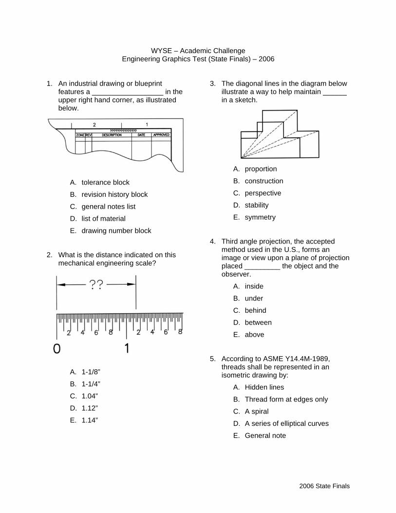
1. An industrial drawing or blueprint
features a __________________ in the upper right hand corner, as illustrated below.
A. tolerance block
B. revision history block
C. general notes list
D. list of material
E. drawing number block
2. What is the distance indicated on this mechanical engineering scale?
A. 1-1/8”
B. 1-1/4”
C. 1.04”
D. 1.12”
E. 1.14”
3. The diagonal lines in the diagram below
illustrate a way to help maintain ______ in a sketch.
A. proportion
B. construction
C. perspective
D. stability
E. symmetry
4. Third angle projection, the accepted method used in the U.S., forms an image or view upon a plane of projection placed _________ the object and the observer.
A. inside
B. under
C. behind
D. between
E. above
5. According to ASME Y14.4M-1989, threads shall be represented in an isometric drawing by:
A. Hidden lines
B. Thread form at edges only
C. A spiral
D. A series of elliptical curves
E. General note
2006 State Finals
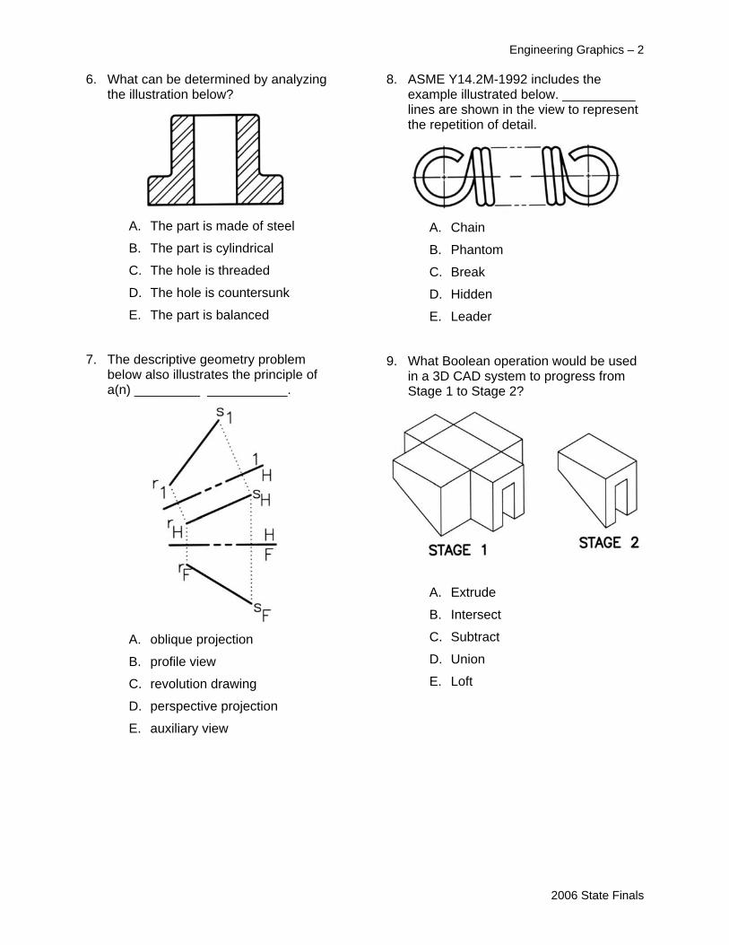
6. What can be determined by analyzing
the illustration below?
A. The part is made of steel
B. The part is cylindrical
C. The hole is threaded
D. The hole is countersunk
E. The part is balanced
7. The descriptive geometry problem below also illustrates the principle of a(n) _________ ___________.
A. oblique projection
B. profile view
C. revolution drawing
D. perspective projection
E. auxiliary view
Engineering Graphics – 2 8. ASME Y14.2M-1992 includes the
example illustrated below. __________ lines are shown in the view to represent the repetition of detail.
A. Chain
B. Phantom
C. Break
D. Hidden
E. Leader
9. What Boolean operation would be used in a 3D CAD system to progress from Stage 1 to Stage 2?
A. Extrude
B. Intersect
C. Subtract
D. Union
E. Loft
2006 State Finals
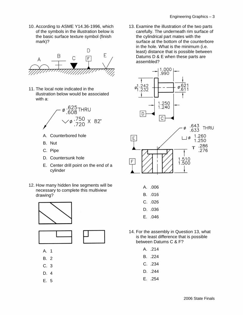
10. According to ASME Y14.36-1996, which of the symbols in the illustration below is the basic surface texture symbol (finish mark)?
11. The local note indicated in the illustration below would be associated with a:
A. Counterbored hole
B. Nut
C. Pipe
D. Countersunk hole
E. Center drill point on the end of a cylinder
12. How many hidden line segments will be necessary to complete this multiview drawing?
A. 1
B. 2
C. 3
D. 4
E. 5
Engineering Graphics – 3 13. Examine the illustration of the two parts
carefully. The underneath rim surface of the cylindrical part mates with the surface at the bottom of the counterbore in the hole. What is the minimum (i.e. least) distance that is possible between Datums D & E when these parts are assembled?
A. .006
B. .016
C. .026
D. .036
E. .046
14. For the assembly in Question 13, what is the least difference that is possible between Datums C & F?
A. .214
B. .224
C. .234
D. .244
E. .254
2006 State Finals
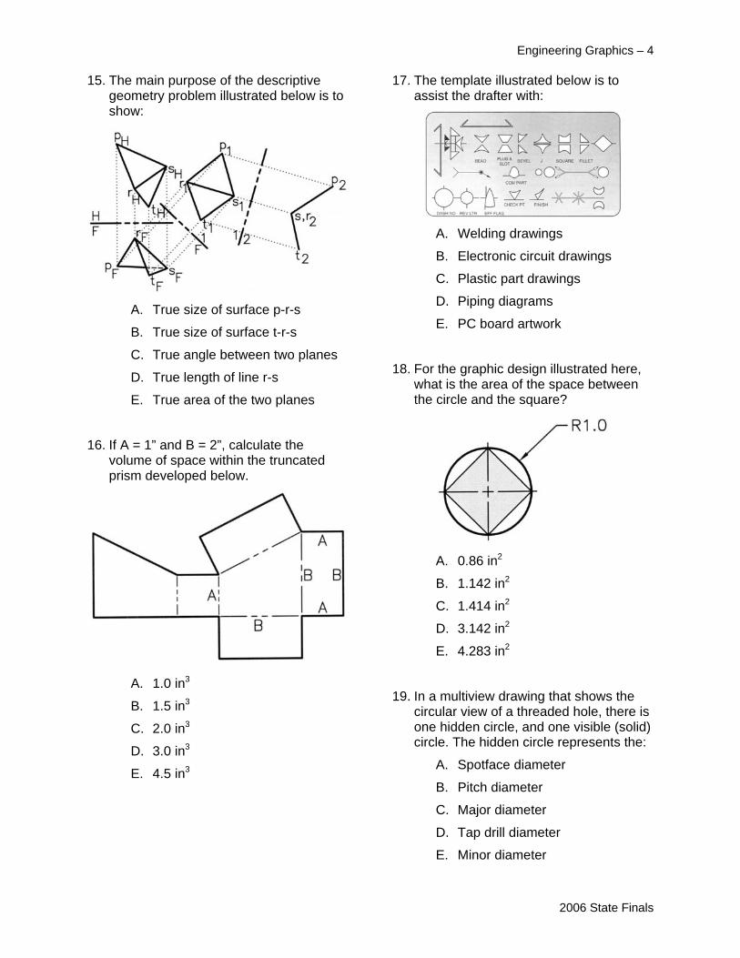
15. The main purpose of the descriptive
geometry problem illustrated below is to show:
A. True size of surface p-r-s
B. True size of surface t-r-s
C. True angle between two planes
D. True length of line r-s
E. True area of the two planes
16. If A = 1” and B = 2”, calculate the volume of space within the truncated prism developed below.
A. 1.0 in3
B. 1.5 in3
C. 2.0 in3
D. 3.0 in3
E. 4.5 in3
Engineering Graphics – 4 17. The template illustrated below is to
assist the drafter with:
A. Welding drawings
B. Electronic circuit drawings
C. Plastic part drawings
D. Piping diagrams
E. PC board artwork
18. For the graphic design illustrated here, what is the area of the space between the circle and the square?
A. 0.86 in2
B. 1.142 in2
C. 1.414 in2
D. 3.142 in2
E. 4.283 in2
19. In a multiview drawing that shows the circular view of a threaded hole, there is one hidden circle, and one visible (solid) circle. The hidden circle represents the:
A. Spotface diameter
B. Pitch diameter
C. Major diameter
D. Tap drill diameter
E. Minor diameter
2006 State Finals

20. Given normal surface “A” parallel with a frontal plane, how many normal surfaces of this object (counting ALL surfaces) are parallel with a right side profile plane?
A. 2
B. 3
C. 4
D. 5
E. 6
21. The purpose of a pictorial drawing is to show:
A. The true size and shape of an inclined surface
B. The internal detail of a feature
C. A cut view of an object
D. A picture-like view of an object
E. A multiview of an object
22. Machining processes are only specified in notes under special conditions that necessitate that process. The note below would most likely be associated with a:
A. Spotweld
B. Thread
C. Bolt
D. Hole
E. Spotface
Engineering Graphics – 5 23. What practice is illustrated in the figure
below?
A. Outline sectioning
B. Surface finish specification
C. Plating callout
D. Broken out section
E. Case hardening specification
24. All auxiliary views projected adjacent to the top view are referred to as _______ auxiliaries because this dimension is always present.
A. length
B. depth
C. height
D. width
E. breadth
25. According to ASME standards, what material is represented by this break?
A. Plastic
B. Wood
C. Metal
D. Glass
E. Ceramic
2006 State Finals
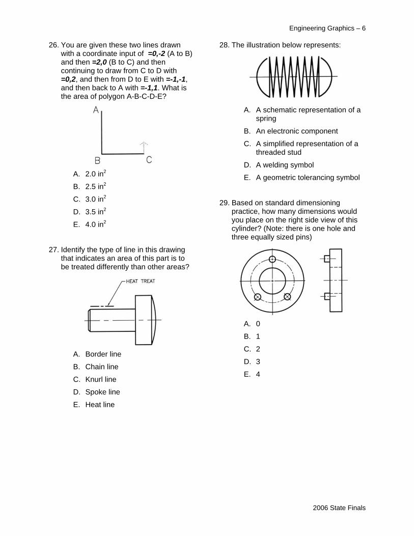
26. You are given these two lines drawn
with a coordinate input of =0,-2 (A to B) and then =2,0 (B to C) and then continuing to draw from C to D with =0,2, and then from D to E with =-1,-1, and then back to A with =-1,1. What is the area of polygon A-B-C-D-E?
A. 2.0 in2
B. 2.5 in2
C. 3.0 in2
D. 3.5 in2
E. 4.0 in2
27. Identify the type of line in this drawing that indicates an area of this part is to be treated differently than other areas?
A. Border line
B. Chain line
C. Knurl line
D. Spoke line
E. Heat line
Engineering Graphics – 6 28. The illustration below represents:
A. A schematic representation of a
spring
B. An electronic component
C. A simplified representation of a threaded stud
D. A welding symbol
E. A geometric tolerancing symbol
29. Based on standard dimensioning practice, how many dimensions would you place on the right side view of this cylinder? (Note: there is one hole and three equally sized pins)
A. 0
B. 1
C. 2
D. 3
E. 4
2006 State Finals
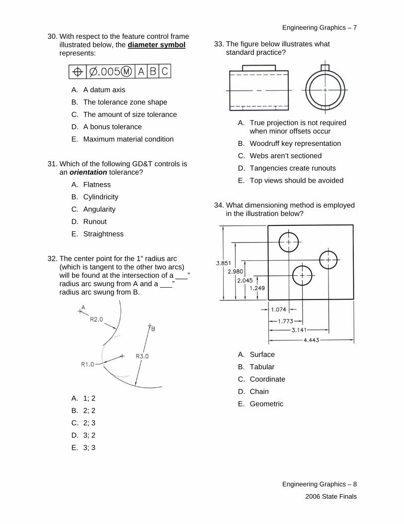
Engineering Graphics – 7 30. With respect to the feature control frame
illustrated below, the diameter symbol represents:
33. The figure below illustrates what standard practice?
A. A datum axis
B. The tolerance zone shape
C. The amount of size tolerance A. True projection is not required
when minor offsets occur D. A bonus tolerance
E. Maximum material condition B. Woodruff key representation C. Webs aren’t sectioned
31. Which of the following GD&T controls is an orientation tolerance? D. Tangencies create runouts
E. Top views should be avoided A. Flatness B. Cylindricity
34. What dimensioning method is employed in the illustration below? C. Angularity
D. Runout
E. Straightness
32. The center point for the 1” radius arc (which is tangent to the other two arcs) will be found at the intersection of a ___” radius arc swung from A and a ___” radius arc swung from B.
A. Surface
B. Tabular
C. Coordinate
D. Chain A. 1; 2
E. Geometric B. 2; 2
C. 2; 3
D. 3; 2
E. 3; 3
Engineering Graphics – 8
2006 State Finals
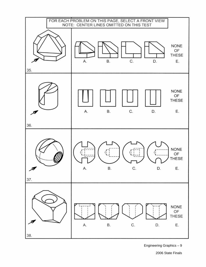
Engineering Graphics – 9
2006 State Finals

Engineering Graphics – 10 2006 State Finals
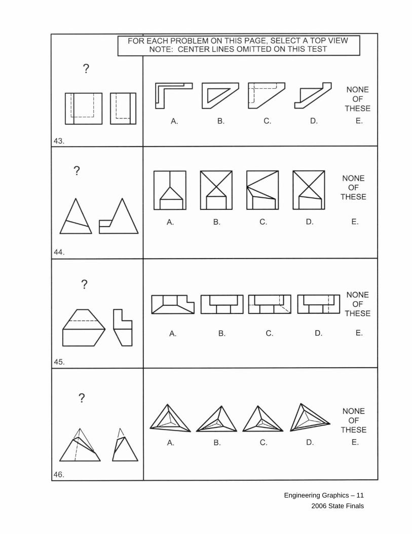
Engineering Graphics – 11 2006 State Finals
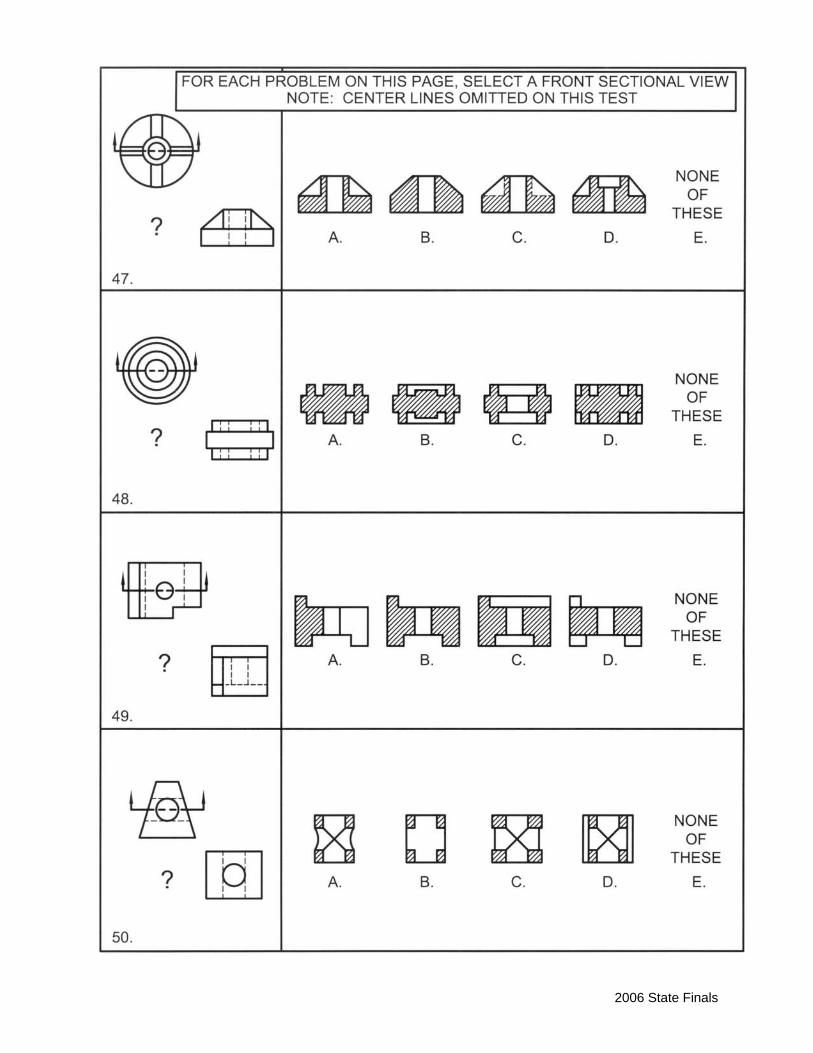
2006 State Finals