2006-2007 Suzuki LTR450
3
i329-411 www.powercommander.com 2006-2007 Suzuki LTR450 - PCIII USB - 1 2006-2007 Suzuki LTR450 Installation Instructions Dynojet Research 2191 Mendenhall Drive North Las Vegas, NV 89081 (800) 992-4993 www.powercommander.com Parts List 1 Power Commander 1 USB Cable 1 CD-ROM 1 Installation Guide 1 Power Adapter 2 Power Commander Decals 2 Dynojet Decals 2 Velcro ® Strip 1 Alcohol Swab 1 Wire tap 1 Rev Extension Plug You can also download the Power Commander software and latest maps from our web site at: www.powercommander.com The ignition MUST be turned OFF before installation! PLEASE READ ALL DIRECTIONS BEFORE STARTING INSTALLATION Button Adjustment Display Faceplate Buttons USB Port Expansion Port
Transcript of 2006-2007 Suzuki LTR450

i329-411 www.powercommander.com 2006-2007 Suzuki LTR450 - PCIII USB - 1
2006-2007 Suzuki LTR450Installation Instructions
Dynojet Research 2191 Mendenhall Drive North Las Vegas, NV 89081 (800) 992-4993 www.powercommander.com
Parts List1 Power Commander1 USB Cable1 CD-ROM1 Installation Guide1 Power Adapter2 Power Commander Decals2 Dynojet Decals2 Velcro® Strip1 Alcohol Swab1 Wire tap1 Rev Extension Plug
You can also download the PowerCommander software and latest mapsfrom our web site at:
www.powercommander.com
The ignition MUST be turnedOFF before installation!
PLEASE READ ALL DIRECTIONS BEFORE STARTING INSTALLATION
Button Adjustment Display
Faceplate Buttons
USB PortExpansion Port

1 Remove the seat.
2 Remove the plastic shroud around thefuel tank.
3 Lay the PCIII in the tail section.
4 Route the wiring harness from thePCIII towards the throttle body.
5 Unplug the stock wiring harness fromthe injector and the Throttle PositionSensor (Fig. A).
6 Plug the connectors from the PCIII in-line of the stock wiring harness andfuel injector (Fig. B).
7 Crimp the supplied wire tap to theYELLOW wire of the stock TPS con-nector (Fig C).
8 Plug the GREY wire from the PCIIIinto the wire tap (Fig. C).
It is recommended to use dielectricgrease on these connections.
9 Plug the TPS connector back onto thethrottle body.
Fig.
AFi
g. B
Fig.
C
i329-411 www.powercommander.com 2006-2007 Suzuki LTR450 - PCIII USB - 2
PCIII connectors
Grey wire from PCIII
Unplug this connector
Unplug the TPSconnector
Stock connector
Stock TPS connector
Wire tap
10 Attach the ground wire from the PCIIIto the common ground on the lefthand side of the engine (Fig. D).
Follow the stock wiring harness.
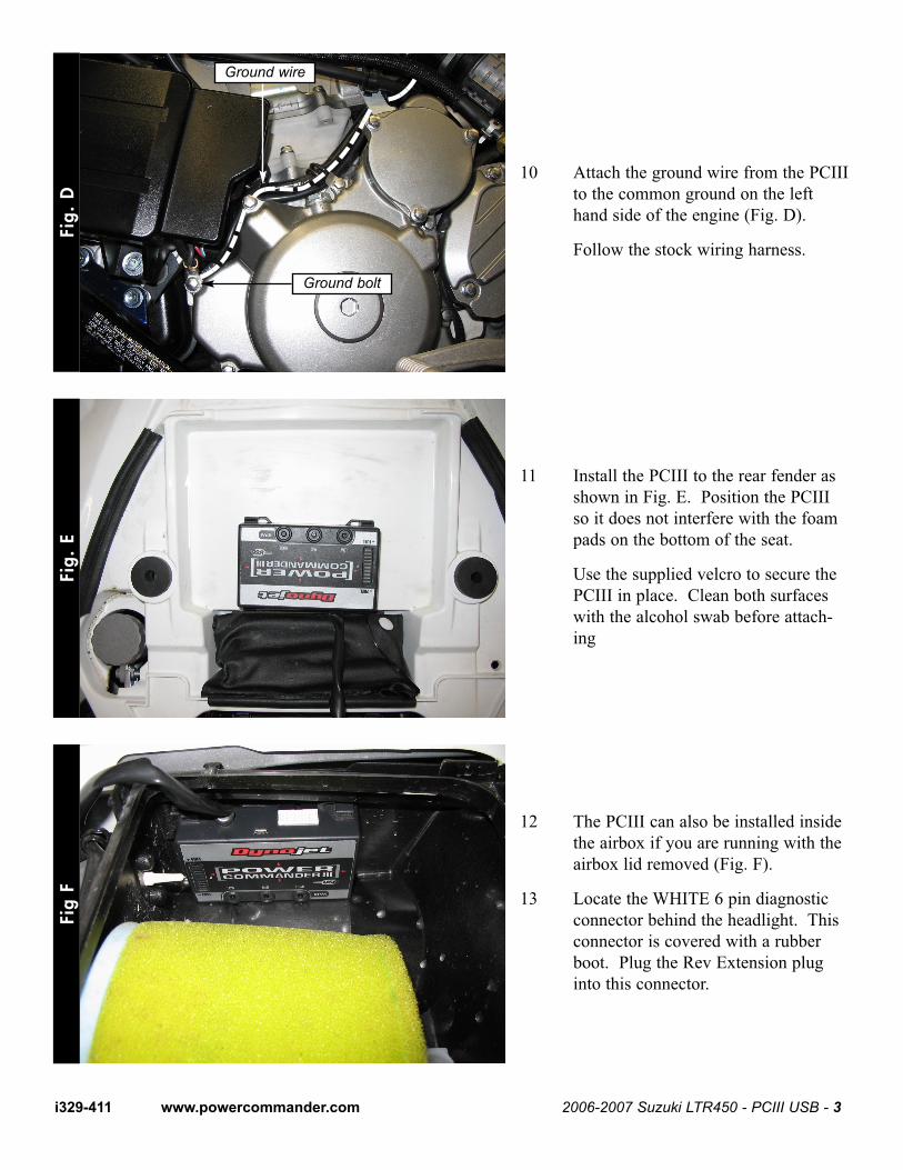
11 Install the PCIII to the rear fender asshown in Fig. E. Position the PCIIIso it does not interfere with the foampads on the bottom of the seat.
Use the supplied velcro to secure thePCIII in place. Clean both surfaceswith the alcohol swab before attach-ing
12 The PCIII can also be installed insidethe airbox if you are running with theairbox lid removed (Fig. F).
13 Locate the WHITE 6 pin diagnosticconnector behind the headlight. Thisconnector is covered with a rubberboot. Plug the Rev Extension pluginto this connector.
Fig.
DFi
g. E
Fig
F
i329-411 www.powercommander.com 2006-2007 Suzuki LTR450 - PCIII USB - 3
Ground wire
Ground bolt