2005 RS Chassis
86
TABLE OF CONTENTS 1. 0 INTRODUCTI ON . . . . . . . . . . . . . . . . . . . . . . . . . . . . . . . . . . . . . . . . . . . . . . . . . . . . . . . . . 1 1.1 SYSTEM COVERAGE . . . . . . . . . . . . . . . . . . . . . . . . . . . . . . . . . . . . . . . . . . . . . . . 1 1.2 SIX-STEP TROU BLESHOOTING PROCEDURE . . . . . . . . . . . . . . . . . . . . . . . . . .1 2. 0 IDENTIFI CA TI ON OF SYSTEM . . . . . . . . . . . . . . . . . . . . . . . . . . . . . . . . . . . . . . . . . . . . . 1 3.0 SYSTEM DESCRIPT ION AND FUNCTIONAL OPERA TION. . . . . . . . . . . . . . . . . . . . . . 1 3.1 TEVES MARK 20e SYSTEM DESCRIPTION . . . . . . . . . . . . . . . . . . . . . . . . . . . . .1 3.2 TRACTI ON CONTR OL SYSTEM (TC S) DESCRIPTION (IF EQUI PPED) . . . . . . .1 3.3 SYSTEM COMPONENTS. . . . . . . . . . . . . . . . . . . . . . . . . . . . . . . . . . . . . . . . . . . . . 2 3.3.1 ABS AND BRAKE WARNING INDICATORS. . . . . . . . . . . . . . . . . . . . . .2 3.3.2 CONTROLLER ANTILOCK BRAKE (CAB) . . . . . . . . . . . . . . . . . . . . . . .2 3.3.3 HYDRAULIC CONTROL UNIT . . . . . . . . . . . . . . . . . . . . . . . . . . . . . . . . . 2 3.3.4 ABS SWITCHES/SENSOR S. . . . . . . . . . . . . . . . . . . . . . . . . . . . . . . . . . . 3 3.3.5 ABS INITIALIZATION . . . . . . . . . . . . . . . . . . . . . . . . . . . . . . . . . . . . . . . . 3 3.3.6 ABS DIAGNOSTIC MODE . . . . . . . . . . . . . . . . . . . . . . . . . . . . . . . . . . . . 3 3.3.7 TRACTION CONTROL OPERA TION (IF EQU IPPED) . . . . . . . . . . . . . .4 3.4 DIAGNOSTIC TROU BLE CODES . . . . . . . . . . . . . . . . . . . . . . . . . . . . . . . . . . . . . .4 3.5 FREEZE FRAME . . . . . . . . . . . . . . . . . . . . . . . . . . . . . . . . . . . . . . . . . . . . . . . . . . . . 4 3.6 DRBIII ERROR MESSAGES AND BLANK SCREEN . . . . . . . . . . . . . . . . . . . . . . 4 3.6.1 DRBIII DOES NOT POWER UP . . . . . . . . . . . . . . . . . . . . . . . . . . . . . . .4 3.6.2 DISPL AY IS NOT VISI BLE . . . . . . . . . . . . . . . . . . . . . . . . . . . . . . . . . . . .4 4. 0 DISCLAIMERS, SAF ETY , WARNINGS . . . . . . . . . . . . . . . . . . . . . . . . . . . . . . . . . . . . . . . 4 4.1 DISCLAIMERS. . . . . . . . . . . . . . . . . . . . . . . . . . . . . . . . . . . . . . . . . . . . . . . . . . . . . . 4 4.2 SAFETY . . . . . . . . . . . . . . . . . . . . . . . . . . . . . . . . . . . . . . . . . . . . . . . . . . . . . . . . . . . 5 4.2.1 T ECHNICIAN SAFETY INFORMATION . . . . . . . . . . . . . . . . . . . . . . . . . . 5 4.2.2 VEHICLE PREPARATION FOR T ESTING. . . . . . . . . . . . . . . . . . . . . . . . 5 4.2.3 SERVICING SUB-ASSEMBLIES . . . . . . . . . . . . . . . . . . . . . . . . . . . . . . . 5 4.2.4 DRBIII SAFETY INFORMATION . . . . . . . . . . . . . . . . . . . . . . . . . . . . . .5 4.3 WARNINGS . . . . . . . . . . . . . . . . . . . . . . . . . . . . . . . . . . . . . . . . . . . . . . . . . . . . . . . . 6 4.3.1 VEHIC LE DAMAGE WARNIN GS . . . . . . . . . . . . . . . . . . . . . . . . . . . . . . . 6 4.3.2 ROAD T ESTING A COMP LAINT V EHICLE . . . . . . . . . . . . . . . . . . . . . . . 6 4.4 DIAGNOSIS . . . . . . . . . . . . . . . . . . . . . . . . . . . . . . . . . . . . . . . . . . . . . . . . . . . . . . . . 6 5. 0 REQUIRED TOOLS AND EQUIPMENT . . . . . . . . . . . . . . . . . . . . . . . . . . . . . . . . . . . . . . 7 6. 0 GLOSSARY OF TERMS. . . . . . . . . . . . . . . . . . . . . . . . . . . . . . . . . . . . . . . . . . . . . . . . . . . 7 7.0 DIAGNOSTIC INFORMA TION AND PROCEDURES . . . . . . . . . . . . . . . . . . . . . . . . . . . . 9 ADJUSTABLE PEDALS INTERNAL CONTROLLER ERROR. . . . . . . . . . . . . . . . . . . . . . . . . . . . . . . . . . . . . . . . .10 PEDAL SENSOR OPEN/SHORTED TO GROUND . . . . . . . . . . . . . . . . . . . . . . . . . . . . .11 PEDAL SENSOR SHORTED TO BATTERY . . . . . . . . . . . . . . . . . . . . . . . . . . . . . . . . . .14 PEDAL SW STUCK FORWARD. . . . . . . . . . . . . . . . . . . . . . . . . . . . . . . . . . . . . . . . . . . .16 PEDAL SW STUCK REARWARD . . . . . . . . . . . . . . . . . . . . . . . . . . . . . . . . . . . . . . . . . .18 SYSTEM OVER VOLTAGE. . . . . . . . . . . . . . . . . . . . . . . . . . . . . . . . . . . . . . . . . . . . . . . .20 SYSTEM UNDER VOLTAGE . . . . . . . . . . . . . . . . . . . . . . . . . . . . . . . . . . . . . . . . . . . . . .22 *CAN’T ADJUST PEDALS . . . . . . . . . . . . . . . . . . . . . . . . . . . . . . . . . . . . . . . . . . . . . . . .24 *CAN’T SET/RECALL MEMORY POSITIONS . . . . . . . . . . . . . . . . . . . . . . . . . . . . . . . . .29 i
-
Upload
orangewedge32 -
Category
Documents
-
view
216 -
download
0
description
2005 rs chasis
Transcript of 2005 RS Chassis

7/21/2019 2005 RS Chassis
http://slidepdf.com/reader/full/2005-rs-chassis 1/86
TABLE OF CONTENTS
1.0 INTRODUCTION . . . . . . . . . . . . . . . . . . . . . . . . . . . . . . . . . . . . . . . . . . . . . . . . . . . . . . . . .1
1.1 SYSTEM COVERAGE . . . . . . . . . . . . . . . . . . . . . . . . . . . . . . . . . . . . . . . . . . . . . . .11.2 SIX-STEP TROUBLESHOOTING PROCEDURE . . . . . . . . . . . . . . . . . . . . . . . . . .1
2.0 IDENTIFICATION OF SYSTEM . . . . . . . . . . . . . . . . . . . . . . . . . . . . . . . . . . . . . . . . . . . . .1
3.0 SYSTEM DESCRIPTION AND FUNCTIONAL OPERATION . . . . . . . . . . . . . . . . . . . . . .1
3.1 TEVES MARK 20e SYSTEM DESCRIPTION . . . . . . . . . . . . . . . . . . . . . . . . . . . . .13.2 TRACTION CONTROL SYSTEM (TCS) DESCRIPTION (IF EQUIPPED) . . . . . . .13.3 SYSTEM COMPONENTS. . . . . . . . . . . . . . . . . . . . . . . . . . . . . . . . . . . . . . . . . . . . .2
3.3.1 ABS AND BRAKE WARNING INDICATORS. . . . . . . . . . . . . . . . . . . . . .23.3.2 CONTROLLER ANTILOCK BRAKE (CAB) . . . . . . . . . . . . . . . . . . . . . . .23.3.3 HYDRAULIC CONTROL UNIT . . . . . . . . . . . . . . . . . . . . . . . . . . . . . . . . .23.3.4 ABS SWITCHES/SENSORS. . . . . . . . . . . . . . . . . . . . . . . . . . . . . . . . . . .33.3.5 ABS INITIALIZATION . . . . . . . . . . . . . . . . . . . . . . . . . . . . . . . . . . . . . . . .33.3.6 ABS DIAGNOSTIC MODE . . . . . . . . . . . . . . . . . . . . . . . . . . . . . . . . . . . .33.3.7 TRACTION CONTROL OPERATION (IF EQUIPPED) . . . . . . . . . . . . . .4
3.4 DIAGNOSTIC TROUBLE CODES . . . . . . . . . . . . . . . . . . . . . . . . . . . . . . . . . . . . . .43.5 FREEZE FRAME. . . . . . . . . . . . . . . . . . . . . . . . . . . . . . . . . . . . . . . . . . . . . . . . . . . .43.6 DRBIII ERROR MESSAGES AND BLANK SCREEN . . . . . . . . . . . . . . . . . . . . . .4
3.6.1 DRBIII DOES NOT POWER UP. . . . . . . . . . . . . . . . . . . . . . . . . . . . . . .43.6.2 DISPLAY IS NOT VISIBLE . . . . . . . . . . . . . . . . . . . . . . . . . . . . . . . . . . . .4
4.0 DISCLAIMERS, SAFETY, WARNINGS . . . . . . . . . . . . . . . . . . . . . . . . . . . . . . . . . . . . . . .4
4.1 DISCLAIMERS. . . . . . . . . . . . . . . . . . . . . . . . . . . . . . . . . . . . . . . . . . . . . . . . . . . . . .44.2 SAFETY . . . . . . . . . . . . . . . . . . . . . . . . . . . . . . . . . . . . . . . . . . . . . . . . . . . . . . . . . . .5
4.2.1 TECHNICIAN SAFETY INFORMATION . . . . . . . . . . . . . . . . . . . . . . . . . .54.2.2 VEHICLE PREPARATION FOR TESTING. . . . . . . . . . . . . . . . . . . . . . . .5
4.2.3 SERVICING SUB-ASSEMBLIES . . . . . . . . . . . . . . . . . . . . . . . . . . . . . . .54.2.4 DRBIII SAFETY INFORMATION . . . . . . . . . . . . . . . . . . . . . . . . . . . . . .5
4.3 WARNINGS . . . . . . . . . . . . . . . . . . . . . . . . . . . . . . . . . . . . . . . . . . . . . . . . . . . . . . . .64.3.1 VEHICLE DAMAGE WARNINGS . . . . . . . . . . . . . . . . . . . . . . . . . . . . . . .64.3.2 ROAD TESTING A COMPLAINT VEHICLE . . . . . . . . . . . . . . . . . . . . . . .6
4.4 DIAGNOSIS . . . . . . . . . . . . . . . . . . . . . . . . . . . . . . . . . . . . . . . . . . . . . . . . . . . . . . . .6
5.0 REQUIRED TOOLS AND EQUIPMENT . . . . . . . . . . . . . . . . . . . . . . . . . . . . . . . . . . . . . .7
6.0 GLOSSARY OF TERMS. . . . . . . . . . . . . . . . . . . . . . . . . . . . . . . . . . . . . . . . . . . . . . . . . . .7
7.0 DIAGNOSTIC INFORMATION AND PROCEDURES . . . . . . . . . . . . . . . . . . . . . . . . . . . .9
ADJUSTABLE PEDALSINTERNAL CONTROLLER ERROR. . . . . . . . . . . . . . . . . . . . . . . . . . . . . . . . . . . . . . . . .10PEDAL SENSOR OPEN/SHORTED TO GROUND . . . . . . . . . . . . . . . . . . . . . . . . . . . . .11PEDAL SENSOR SHORTED TO BATTERY . . . . . . . . . . . . . . . . . . . . . . . . . . . . . . . . . .14PEDAL SW STUCK FORWARD. . . . . . . . . . . . . . . . . . . . . . . . . . . . . . . . . . . . . . . . . . . .16PEDAL SW STUCK REARWARD . . . . . . . . . . . . . . . . . . . . . . . . . . . . . . . . . . . . . . . . . .18SYSTEM OVER VOLTAGE. . . . . . . . . . . . . . . . . . . . . . . . . . . . . . . . . . . . . . . . . . . . . . . .20SYSTEM UNDER VOLTAGE . . . . . . . . . . . . . . . . . . . . . . . . . . . . . . . . . . . . . . . . . . . . . .22*CAN’T ADJUST PEDALS . . . . . . . . . . . . . . . . . . . . . . . . . . . . . . . . . . . . . . . . . . . . . . . .24*CAN’T SET/RECALL MEMORY POSITIONS . . . . . . . . . . . . . . . . . . . . . . . . . . . . . . . . .29
i

7/21/2019 2005 RS Chassis
http://slidepdf.com/reader/full/2005-rs-chassis 2/86
TABLE OF CONTENTS - Continued
BRAKES (CAB)BUS SYSTEM COMMUNICATION FAILURE . . . . . . . . . . . . . . . . . . . . . . . . . . . . . . . . .31CAB INTERNAL FAILURE . . . . . . . . . . . . . . . . . . . . . . . . . . . . . . . . . . . . . . . . . . . . . . . .33CLUSTER LAMP FAILURE. . . . . . . . . . . . . . . . . . . . . . . . . . . . . . . . . . . . . . . . . . . . . . . .35INCORRECT TONE WHEEL FAILURE . . . . . . . . . . . . . . . . . . . . . . . . . . . . . . . . . . . . . .37LEFT FRONT SENSOR CIRCUIT FAILURE . . . . . . . . . . . . . . . . . . . . . . . . . . . . . . . . . .38LEFT REAR SENSOR CIRCUIT FAILURE . . . . . . . . . . . . . . . . . . . . . . . . . . . . . . . . . . .38
RIGHT FRONT SENSOR CIRCUIT FAILURE . . . . . . . . . . . . . . . . . . . . . . . . . . . . . . . . .38RIGHT REAR SENSOR CIRCUIT FAILURE . . . . . . . . . . . . . . . . . . . . . . . . . . . . . . . . . .38LEFT FRONT WHEEL SPEED SIGNAL FAILURE . . . . . . . . . . . . . . . . . . . . . . . . . . . . .43LEFT REAR WHEEL SPEED SIGNAL FAILURE . . . . . . . . . . . . . . . . . . . . . . . . . . . . . .43RIGHT FRONT WHEEL SPEED SIGNAL FAILURE . . . . . . . . . . . . . . . . . . . . . . . . . . . .43RIGHT REAR WHEEL SPEED SIGNAL FAILURE . . . . . . . . . . . . . . . . . . . . . . . . . . . . .43PUMP CIRCUIT FAILURE . . . . . . . . . . . . . . . . . . . . . . . . . . . . . . . . . . . . . . . . . . . . . . . .46SYSTEM OVER VOLTAGE. . . . . . . . . . . . . . . . . . . . . . . . . . . . . . . . . . . . . . . . . . . . . . . .50SYSTEM UNDER VOLTAGE . . . . . . . . . . . . . . . . . . . . . . . . . . . . . . . . . . . . . . . . . . . . . .53VALVE POWER FEED FAILURE . . . . . . . . . . . . . . . . . . . . . . . . . . . . . . . . . . . . . . . . . . .55*BRAKE LAMP SWITCH INOPERATIVE . . . . . . . . . . . . . . . . . . . . . . . . . . . . . . . . . . . . .58*TRAC OFF INDICATOR NEVER/ALWAYS ON . . . . . . . . . . . . . . . . . . . . . . . . . . . . . . .59
*TRAC ON INDICATOR NEVER/ALWAYS ON . . . . . . . . . . . . . . . . . . . . . . . . . . . . . . . .62
COMMUNICATION*NO RESPONSE FROM ADJUSTABLE PEDALS ASSEMBLY . . . . . . . . . . . . . . . . . . .63*NO RESPONSE FROM CONTROLLER ANTILOCK BRAKE . . . . . . . . . . . . . . . . . . . .65
VERIFICATION TESTSVERIFICATION TESTS . . . . . . . . . . . . . . . . . . . . . . . . . . . . . . . . . . . . . . . . . . . . . . . . . . .67
8.0 COMPONENT LOCATIONS . . . . . . . . . . . . . . . . . . . . . . . . . . . . . . . . . . . . . . . . . . . . . . .69
8.1 CONTROLLER ANTILOCK BRAKE (CAB) . . . . . . . . . . . . . . . . . . . . . . . . . . . . . .69
8.2 DATA LINK CONNECTOR . . . . . . . . . . . . . . . . . . . . . . . . . . . . . . . . . . . . . . . . . . .698.3 FUSES . . . . . . . . . . . . . . . . . . . . . . . . . . . . . . . . . . . . . . . . . . . . . . . . . . . . . . . . . . .698.4 TRACTION CONTROL SWITCH . . . . . . . . . . . . . . . . . . . . . . . . . . . . . . . . . . . . . .70
8.4.1 TRACTION CONTROL INDICATORS . . . . . . . . . . . . . . . . . . . . . . . . . .708.5 WHEEL SPEED SENSORS . . . . . . . . . . . . . . . . . . . . . . . . . . . . . . . . . . . . . . . . . .70
8.5.1 FRONT. . . . . . . . . . . . . . . . . . . . . . . . . . . . . . . . . . . . . . . . . . . . . . . . . . .708.5.2 REAR . . . . . . . . . . . . . . . . . . . . . . . . . . . . . . . . . . . . . . . . . . . . . . . . . . . .71
8.5A WHEEL SPEED SENSOR CONNECTORS. . . . . . . . . . . . . . . . . . . . . . . . . . . . . .718.5A.1 FRONT. . . . . . . . . . . . . . . . . . . . . . . . . . . . . . . . . . . . . . . . . . . . . . . . . . .718.5A.2 REAR . . . . . . . . . . . . . . . . . . . . . . . . . . . . . . . . . . . . . . . . . . . . . . . . . . . .71
8.6 BRAKE LAMP SWITCH . . . . . . . . . . . . . . . . . . . . . . . . . . . . . . . . . . . . . . . . . . . . .72
9.0 CONNECTOR PINOUTS . . . . . . . . . . . . . . . . . . . . . . . . . . . . . . . . . . . . . . . . . . . . . . . . .73
ABS PUMP MOTOR (COMPONENT SIDE) - 2 WAY . . . . . . . . . . . . . . . . . . . . . . . . . . .73BRAKE LAMP SWITCH - BLACK 6 WAY . . . . . . . . . . . . . . . . . . . . . . . . . . . . . . . . . . . .73CONTROLLER ANTILOCK BRAKE - BLACK 24 WAY . . . . . . . . . . . . . . . . . . . . . . . . . .74DATA LINK CONNECTOR - BLACK 16 WAY . . . . . . . . . . . . . . . . . . . . . . . . . . . . . . . . .74FUSES (IPM) . . . . . . . . . . . . . . . . . . . . . . . . . . . . . . . . . . . . . . . . . . . . . . . . . . . . . . . . . . .76LEFT FRONT WHEEL SPEED SENSOR - GRAY 2 WAY . . . . . . . . . . . . . . . . . . . . . . .76LEFT REAR WHEEL SPEED SENSOR - BLACK 2 WAY. . . . . . . . . . . . . . . . . . . . . . . .77RIGHT FRONT WHEEL SPEED SENSOR - GRAY 2 WAY . . . . . . . . . . . . . . . . . . . . . .77RIGHT REAR WHEEL SPEED SENSOR - BLACK 2 WAY . . . . . . . . . . . . . . . . . . . . . .77
ii

7/21/2019 2005 RS Chassis
http://slidepdf.com/reader/full/2005-rs-chassis 3/86
TABLE OF CONTENTS - Continued
10.0 SCHEMATIC DIAGRAMS. . . . . . . . . . . . . . . . . . . . . . . . . . . . . . . . . . . . . . . . . . . . . . . . .79
10.1 TEVES MARK 20E ANTILOCK BRAKE SYSTEM – ABS . . . . . . . . . . . . . . . . . . .79
iii

7/21/2019 2005 RS Chassis
http://slidepdf.com/reader/full/2005-rs-chassis 4/86
NOTES
iv
7/21/2019 2005 RS Chassis
http://slidepdf.com/reader/full/2005-rs-chassis 5/86
1.0 INTRODUCTION
The procedures contained in this manual include
a ll t h e sp ecif ica t io n s, in st r u ct ion s, a n d g r a p h ics
n ee de d t o d i a g nos e t h e 2005 C h r y s le r Tow n &
C ou n t r y, D od g e C a r a v a n , a n d C h r y s le r Voy a g er
M a r k 20e An t i lock B r a k in g S y s t em (AB S ) , a n d
Mark 20e Antilocke Bra king S ystem with Traction
Control. The diagnostics in this manual are basedon the failure condition or symptom being present
at t ime of diagnosis.
Please follow the recommendations below when
choosing your diagn ostic path.
1. F i r st m a k e su r e t h e D R B I I I is communicating
w i t h t h e C A B . I f t h e D R B I I I d is pl a y s a “ N o
Re spon se” con d it ion , y ou m u st d ia g n ose t h a t
first .
2. Read DTC’s (diagnostic trouble codes) with the
D R B I I I.
3 . I f n o D TC ’s a r e p r esen t , id en t i f y t h e cu st om e r
complaint.4. Once the DTC or customer complaint is identi-
f ie d , loca t e t h e m a t ch in g t e st in t h e Ta b le o f
Contents and begin to diagnose the symptom.
All component location views are in Section 8.0.
All connector pinouts are in Section 9.0. All sche-
ma tics a re in S ection 10.0.
An a sterisk (*) placed before t he sym ptom descrip-
tion indicat es a concern with no associat ed DTC.
When repairs are required, refer to the appropri-
a t e s er v ice m a n u a l f or t h e p rop er r em ov a l a n d
repair procedure.
Dia gnostic procedures cha nge every year. New
d ia g n o st ic sy st e m s m a y b e a d d e d ; ca r r y o ve r sy s-
t e ms m a y b e e n h a n ce d. R E AD TH I S M AN U AL
B E F O R E TR YI N G TO D I AG N O S E A VE H I C L E
C O D E . I t i s r e com m en d ed t h a t y ou r ev iew t h e
e n t ir e m a n u a l t o b e com e f a m ilia r w it h a l l n e w a n d
changed diagnostic procedures.
After using t his book, if you ha ve an y comments
or r ecommenda tions, please fill out the form a t the
back of the book and mail it back to us.
1. 1 SYSTEM COVERAGE
This dia gnostic procedure ma nua l covers th e a n-
tilock braking system (ABS), and the traction con-
trol system found on: C hrysler Town a nd Country,
Dodge Caravan, and Chrysler Voyager.
1. 2 SIX-STEP TROUBLESHOOTINGPROCEDURE
Diagnosis of the controller antilock brake module
is done in six ba sic steps:
• verification of complaint
• verificat ion of any related symptoms
• sy m p t om a n a ly sis
• problem isolation
• repair of isolated problem
• verifica tion of proper operat ion
2.0 IDENTIFICATION OFSYSTEM
Vehicles equipped with the Teves Mark 20e a n-
tilock brake system can be identified by the pres-
ence of th e contr oller a ntilock brake m odule locat ed
beneath the master cylinder.
The presence of the Traction Control syst em is
in d ica t e d b y t h e T RA C O F F sw it ch o n t o p o f t h e
steering column shroud.
3.0 SYSTEM DESCRIPTION ANDFUNCTIONAL OPERATION
3. 1 TEVES M ARK 20e SYSTEMDESCRIPTION
The controller antilock brake module is used to
m on it or w h e e l sp e ed s a n d t o m od u la t e (con t r o l)
h y d ra u l ic p re ss u r e i n e a ch b r a k e ch a n n el . Th e
m o d u la t e d h y d r a u lic p r e ssu r e is u se d t o p r e ve n t
wheel lock-up during braking.
The Teves Mar k 20e system uses a dia gonal s plit
h y dr a u li c b r a k e s ys t em . I n t h e s t a n da r d b ra k e
mode the master cylinder primary circuit supplies
p res s ur e t o t h e r i gh t f r on t a n d l ef t r ea r w h e el
brakes, and the secondary master cylinder circuit
su p p lie s p r e ssu r e t o t h e le f t f r o n t a n d r ig h t r e a r
wheel brakes.
All vehicles equipped with AB S use E lectronic
Va r ia b le B r a k e P r op or t ion in g (EV PB ) t o b a la n ce
f r o n t - t o - r e a r b r a k in g w h e n b r a k e s a r e a p p lie d in
t h e p a r t ia l b r a k in g r a n g e .
3. 2 TRACTION CONTROL SYSTEM (TCS)
DESCRIPTION (I F EQUIPPED)The main purpose of traction control is to reduce
w h eel s li p a n d m a i nt a i n t r a ct ion a t t h e d ri ven
wheels when road surfaces are slippery. The trac-
tion control system reduces wheel slip by braking
t h e w h e el t h a t i s l os in g t r a c t ion . Th e s y s t em i s
designed to operate at speeds below 56 km/h (35
mph).
1
GENERAL INFORMATION

7/21/2019 2005 RS Chassis
http://slidepdf.com/reader/full/2005-rs-chassis 6/86
3. 3 SYSTEM COMPONENTS
ABS
• controller antilock brake (CAB)
• vacuum booster
• master cylinder
• AB S i nt eg ra t e d el ect r on ic con t r ol m od u le/
hydra ulic control unit (HC U), valve block a ssem-b ly : 8 va lve solen oid s (4 in le t va lves, 4 ou t let
valves, 2 accumulators) 1 pump.
• 4 w heel speed sensor/tone w heel a ssemblies
• AB S w a r n in g in d ica t or
• f u se s a n d w ir in g h a r n e ss
• fluid reservoir
ABS With Traction Control
• CAB with Traction Control program ming
• HC U w it h t w o a d d it ion a l con t r o l va lve s
•
TRAC ON /OFF S w itch• TRAC /TRAC OF F in dica t ors
3. 3. 1 ABS AND BRAKE WARNING
INDICATORS
Th e a m b er A B S w a r n in g in d ica t o r is lo ca t e d in
t h e i n st r u m en t cl us t er. I t i s u s e d t o i n f or m t h e
d r ive r t h a t t h e a n t i lo ck f u n ct io n h a s b e e n t u r n e d
off. The AB S wa rning indicat or is controlled by the
CAB. The CAB controls the lamp with a command
over t h e P C I b u s.
The AB S Wa rning I ndicat or will remain lit du ring
every key cycle until a circuit or component fault isr e pa ir e d a n d t h e C AB n o lon g er d e t ect s t h e f a u lt .
After repair of a sensor signa l fault or a pum p motor
f a u lt , t h e C A B m u s t s e n se a l l f ou r w h ee ls a t 25
km/h (15 mph) before it wi ll extingu ish t he AB S a nd
TRAC OFF Indicators.
The Instrument Cluster will illuminate the ABS
Warn ing I ndicator if it loses communication w ith
t h e C A B .
The red B RAKE wa rning indicator is a lso locat ed
i n t h e i n st r u m en t cl us t er. I t ca n b e a ct i va t e d i n
severa l w ays. Application of the par king brake or a
low fluid signa l from the fluid level swit ch locat ed in
the ma ster cylinder reservoir w ill cause t he indica-tor to come on.
3. 3. 2 CONTROLLER ANTILOCK BRAKE
(CAB)
Th e C on t r ol ler An t il ock B r a k e (C AB ) i s a
microprocessor-based device tha t monitors wheel
sp ee d s a n d con t r o ls t h e a n t i lock f u n ct ion s. Th e
C AB con t a in s t w o m icr op r ocessor s t h a t r e ce ive
id en t ica l se n sor sig n a ls a n d t h e n in d ep en d e n t ly
process the informa tion. The results ar e th en com-
pared to make sure that they agree. Otherwise, the
CAB w ill turn off the ant ilock and t urn on the AB S
amber warning indicator.
The primary functions of the C AB are to:
• detect wheel locking tendencies
• control f luid pressure modulation to the brakes
during a ntilock stop
• monitor the system for proper operation
• m an age t ra ction control functions
• provide communication to the DRBIII while in
diagnostic mode
• store diagn ostic informa tion in non-volatile mem-
or y
The CAB cont inuously monitors t he speed of each
wheel. When a wheel locking tendency is detected,
t h e C AB w i l l c om m a n d t h e a p pr op ri a t e v a l ve t o
modulat e brake fluid pressure in its h ydra ulic unit .
B r a k e p e d a l p o sit io n is m a in t a in e d d u r in g a n a n -
t i lock st op b y b ein g a close d sy st e m . Th e C A Bcontinues to control pressure in individua l hydr au-
lic cir cu it s u n t i l a w h e el lockin g t e n d en cy is n o
longer present. The CAB turns on the pump motor
during an antilock stop.
Th e a n t i lock b r a k e sy st e m is con st a n t ly m on i-
tored by t he C AB for proper opera tion. If t he C AB
d et e ct s a s y s t em m a l fu n ct i on , i t ca n d is a b le t h e
a n t i lock s ys t em a n d t u rn on t h e AB S w a r n in g
in d ica t or . I f t h e a n t i lock f u n ct ion is d isa b le d , t h e
sy st e m w il l r e ve r t t o st a n d a r d b a se b r a k e sy st e m
operation.
The CAB inputs include the following:
• diagnostic communication
• four wheel speed sensors
• th ree pow er feeds: va lve, pump, and m icroproces-
sor
• b r a k e sw it ch
• t ra ction control sw itch
The CAB outputs include the following:
• AB S w a r n in g in d ica t or a ct u a t ion
• 12 volts power to wheel speed sensors
• eight valves
• ten valves with traction control
• diagnostic communication
• PCI bus communication
• t ra ction control lam p illumination
3. 3. 3 HYDRAULIC CONTROL UNIT
Th e h y d r a u lic con t r o l u n it (HC U ) con t a in s t h e
valve block assembly, an d pump/motor assembly.
Th e HC U is a t t a ch ed t o t h e C A B .
Valve Block Assembly: The valve block assem-
bly contains valves with four inlet valves and four
2
GENERAL INFORMATION

7/21/2019 2005 RS Chassis
http://slidepdf.com/reader/full/2005-rs-chassis 7/86
outlet valves. The inlet valves are spring-loaded in
the open posit ion and the outlet valves are spring
lo a d e d in t h e clo se d p o sit io n . D u r in g a n a n t i lo ck
stop, th ese valves are cycled to ma inta in t he proper
slip rat io for ea ch wheel. I f a wheel detects slip, the
inlet valve is closed to prevent and further pressure
increase. Then the outlet valve is opened to release
the pressure to the a ccumulat ors until the w heel is
n o lon g e r sl ip pin g . O n ce t h e w h e el is n o lon g ersl ip pin g , t h e ou t let va lve is close d a n d t h e in le t
valve is opened to rea pply pressure. If th e wh eel is
d ecel er a t in g w i t hi n i t s p red et er m in ed l im it s
(proper slip ratio), the inlet valve will close to hold
t h e pr es su r e con s t a nt . O n v eh icl es w h ich a r e
equipped with a traction control system, there are
t w o a d d it ion a l va lves t h a t isola t e t h e m a st e r cy lin -
der and rear wheels. During a traction control event
the bra kes are applied t o reduce wh eel slippage.
Pump Motor Assembly: The pump motor as-
sembly provides the extra amount of f luid needed
during a nt ilock braking . The pump is supplied fluid
tha t is released to the accumulat ors when the outletvalve is opened during an an tilock stop. The pump
is also used to drain the accumulator circuits after
the a ntilock stop is complete. The pump is operat ed
b y a n in t e gr a l e le ct r ic m o t o r. Th is m ot o r is con -
trolled by the CAB. The CAB ma y tur n on the pump
motor when an antilock stop is detected. The pump
co n t in u e s t o r u n d u r in g t h e a n t i lo ck st o p a n d is
turned off after the stop is complete. Under some
co n d it io n s, t h e p u m p m o t o r w il l r u n t o d r a in t h e
accumulators during the next drive off . The CAB
monitors the pump motor operat ion internally.
3. 3. 4 ABS SWITCHES/SENSORSMaster Cylinder: The mast er cylinder is a sta n-
dard ta ndem compensating port design for AB S a nd
non AB S systems. Traction control vehicles use a
dual center port master cylinder. For proper trac-
tion control operation th e sta nda rd m ast er cylinder
must not be used.
A f lu id l ev el s w i t ch i s l oca t e d i n t h e m a s t e r
cylinder fluid reservoir . The switch closes when a
low fluid level is detected. The fluid level sw itch
turns on the brake warning indicator by grounding
the indicator circuit . This switch does not disable
t h e AB S sy st e m .Wheel Speed Sensors and Tone Wheels: On e
active wheel speed sensor (WSS) is located at each
w h e e l a n d se n d s a sm a ll D C sig n a l t o t h e co n t r o l
m od u le (C A B ). Th is sig na l is g en e r a t e d w h e n a
toothed sensor ring (tone wheel)passes by a station-
a r y w h e e l sp ee d se n sor. Th e C AB con ver t s t h e
signals for each w heel.
Because of internal circuitry, correct wheel speed
sensor function cannot be determined by a continu-
ity or resistance check t hrough th e sensor.
The front w heel speed sensor is at ta ched to a boss
i n t h e s t ee ri n g k n uck le . Th e t on e w h e el i s a n
integral pa rt of the front axle sha ft . The rear speed
sensor is mounted though the bearing cover and the
r ea r t on e w h e el i s a n i nt eg ra l pa r t of t h e r e a r
bearing hub. The w heel speed sensor a ir ga p is n ot
a d ju st a b le . Re f e r t o t h e se r vice m a n u a l f o r w h e e l
speed sensor a ir ga p a nd resistance specificat ions.
The four wheel speed sensors are serviced indi-vidually. The front tone wheels are serviced as an
a sse m b ly w it h t h e ou t e r con st a n t velocit y (C .V.)
joint housing. The rear tone wheels are serviced as
an assembly.
Correct antilock system operation is dependent
on tone wheel speed signals from the wheel speed
sensors. The vehicle’s w heels an d t ires should a ll be
the sam e size and t ype to generat e accura te signals.
I n a d d i t ion , t h e t i r es s h ou ld b e i n fl a t e d t o t h e
recommended pressure for optimum system opera-
tion. Varia t ion in w heel and t ire size or significan t
variations in inflation pressure can produce inaccu-
rate wheel speed signals; however, the system willcontinue to function when using the correct factory
mini-spare.
3. 3. 5 ABS INITIALIZATION
S y s t em i ni t ia l iz a t ion s t a r t s w h en t h e k ey i s
turned to “run”. At this point , the CAB performs a
complete self-check of all electrical components in
the antilock systems.
B etw een 8-17 km/h (5-10 mph), a d yn a mic t est i s
performed. This will momenta rily cycle t he inlet
a n d ou t let va lves, ch eck w h e el sp ee d se n sor cir -
cu it r y, a n d r u n t h e p u m p m o t or a t 25 k m /h (15mph). The CAB will try to test the pump motor. If
the bra ke pedal is a pplied the test w ill be run a t 40
km/h (24 mph) regard less of brake s wit ch sta te. I f,
during the dyna mic test , the bra ke pedal is a pplied,
t h e d r ive r m a y f e e l t h e t e st t h r o u g h b r a k e p e d a l
pulsations. This is a normal condition.
I f a n y com p on e n t e xh ib it s a t r o ub le con d it ion
during system init ialization or dynamic check, the
CAB will illuminat e the AB S w ar ning indicat or and
TRAC OFF lamp if equipped.
3.3. 6 ABS DIAGNOSTIC MODE
To enter dia gnostic mode, a vehicle speed must beb elow 10 k m /h (6 m p h ) a n d n o A B S con d it ion
p r ese n t . I f veh icle sp ee d is n ot b elow 10 k m /h
(6 m p h ), a “N o Re spon se” m e ssa g e cou ld b e d is-
p la y e d b y t h e D R B I I I. The following are charac-
teristics of diagnostic mode:
– T h e a m b e r A B S w a r n in g in d ica t o r w il l b l in k
rapidly. If a hard trouble code, such as Valve
Power Feed Failure code is present, the indi-
cator will be illuminat ed without blinking un-
til t he t rouble condition is cleared.
3
GENERAL INFORMATION

7/21/2019 2005 RS Chassis
http://slidepdf.com/reader/full/2005-rs-chassis 8/86
– Antilock opera tion is disa bled.
– Th e HC U va lves ca n n ot b e a ct u a t e d w h e n t h e
vehicle speed is a bove 8 km/h (5 mph). If v a lve
a ctua tion is a tt empt ed ab ove 8 km/h (5 mph ), a
“No Response” message will be displayed on
t h e D R B I I I.
3. 3. 7 TRACTION CONTROL OPERATION
(IF EQUIPPED)
The Controller Antilock B ra ke (CAB) monitors
wheel speeds. If , during acceleration, the module
detects front (drive) wheel slip and the brakes are
n ot a p p lied , t h e C A B w il l e n t e r t r a ct ion con t r o l
mode. Tra ction contr ol works in the following order
when drive wheel slip is detected.
1. Close the (norma lly open) isolat ion valves.
2. St a rt pump/motor a nd supply volume/pressure
to front hydraulic circuits (pump runs continu-
ously during traction control).
3. Open a nd close build and d ecay valves to main-t a i n m i n i m u m w h e e l s l i p a n d m a x i m u m t r a c -
tion.
Th e cy cl in g of t h e b u il d a n d d eca y v a l ve s i s
similar t o the AB S except th at they w ork to control
wheel spin by applying brakes. ABS function is to
control w heel skid by releasing brakes.
Tw o pressure relief va lves a llow excess fluid vol-
ume to return to the reservoir when not used by the
build/decay cycles. These a re r equired because the
pump supplies more volume tha n the t raction con-
trol system requires.
If at an y t ime the brake pedal is a pplied during a
t r a ct ion con t r o l cy cle, t h e b r a k e la m p sw it ch w il ltr igger the C AB to swit ch off the t ra ction control.
T h e t r a ct io n co n t r o l sy st e m w il l b e e n a b le d a t
each ignition cycle. It may be turned off by depress-
ing t he Traction C ontrol S witch. The t raction con-
t r o l sy st e m f u n ct ion la m p w il l i llu m in a t e “TRAC
O F F ” im m ed ia t e ly u p on d e pr e ssin g t h e t r a ct ion
control sw itch butt on. Only t he “TRAC” portion of
the “TRAC OFF” indicat or will illuminate during a
traction control event.
I f t h e C A B ca l cu la t e s t h a t t h e b r a k e t e m pe ra -
t u r es a r e h i gh , t h e t r a c t ion con t r ol s y st e m w i l l
b ecom e in op er a t ive u n t i l a t im e -ou t p er iod h a s
elapsed. When in this thermal protection mode, the
tra ction control “TRAC OFF” lamp w ill illuminat e;
however, a fa ult w ill not be registered.
3. 4 DIAGNOSTIC TROUBLE CODES
The Controller Antilock Brake may report any of
several Dia gnostic Trouble Codes (DTC)s. For a list
of the DTCs diagnosed in this manual, refer to the
Ta ble of Cont ents.
3.5 FREEZE FRAME
Freeze Frame ta kes a “snapshot” of specific vehi-
cle informa tion the insta nt an ABS failure is recog-
n i ze d a n d s t or es t h i s i n for m a t i on i n t o t h e C AB
memory. This informa tion can be accessed using th e
D R B I I I t o h e lp d ia g n ose t h e f a u lt . F r e e z e F r a m e
w i l l c a pt u r e t h e f ir s t t i m e f a i lu r e o r o n ly a n ew
failur e tha t occurs during th e current ign ition cycle.
3.6 DRBI II ERROR MESSAGES ANDBLANK SCREEN
U n d e r n o r m a l o p e r a t io n , t h e D RB I I I w il l d is-
play one of only t wo error messages:
– U s er -R eq ues t ed WAR M B oot or U s er -
Requested COLD Boot.
I f t h e D R B I I I sh ou ld d ispla y a n y ot h e r e r r or
m es s a g e, r ecor d t h e en t i r e d i s pl a y a n d ca l l t h e
S TAR C e n t e r. Th is is a sa m p le o f su ch a n e r r or
message display:ver: 2.14da te: 26 J ul93file: key_itf.ccdate: J ul 26 1993line: 548err. 0x1User-Requested COLD boot P ress MORE t oswitch between this display
and the application screen.P ress F4 w hen done noting informa tion.
3.6.1 DRBI II DOES NOT POWER UP
If the LED’s do not light or no sound is emitted atstart up, check for loose cable connections or a bad
cable. Check the vehicle battery voltage (data link
con n e ct o r ca vit y 16). A m in im u m of 11 volt s is
r e q u ir e d t o a d e q u a t e ly p ow e r t h e D RB I I I.
I f a l l con n ect i on s a r e p rop er a n d t h e v eh i cl e
b a t t e ry i s f ul ly ch a r g ed , a n i n op er a t i v e D R B I I I
ma y be t he result of faulty cable or vehicle wiring.
3.6. 2 DISPLAY IS NOT VISIBLE
Low temperatures will affect the visibility of the
display. Adjust t he contra st to compensate for this
condition.
4.0 DISCLAIMERS, SAFETY,WARNINGS
4.1 DISCLAIMERS
All information, illustrations, and specifications
con t a i n ed i n t h i s m a n u a l a r e b a s e d o n t h e l a t e s t
4
GENERAL INFORMATION
7/21/2019 2005 RS Chassis
http://slidepdf.com/reader/full/2005-rs-chassis 9/86
in for m a t ion a va ila b le a t t h e t im e o f p u b lica t ion .
The right is reserved to make changes at any t ime
without notice.
4.2 SAFETY
4. 2. 1 TECHNICIAN SAFETY INFORM ATION
WARNING: ENGINES PRODUCE CARBONMONOXIDE THAT IS ODORLESS, CAUSESSLOWER REACTION TIME, AND CAN LEADTO SERIOUS INJURY. WHEN THE ENGINE ISOPERATING, KEEP SERVICE AREAS WELLVENTILATED OR ATTACH THE VEHICLEEXHAUST SYSTEM TO THE SHOP EXHAUSTREMOVAL SYSTEM.
Set t he parking bra ke and block the wh eels beforet e st in g o r r e pa ir in g t h e veh icle. I t is e spe cia l ly
importa nt to block t he w heels on front-wh eel drive
vehicles; the parking brake does not hold the drive
wheels.
When servicing a vehicle, always wear eye pro-
t e ct i on , a n d r em ov e a n y m et a l je w el r y s u c h a s
r in g s, w a t ch ba n d s o r b r a celet s t h a t m ig h t m a k e a n
inadvertent electrical conta ct .
When dia gnosing a chassis problem, it is impor-
ta nt to follow approved procedures where applica-
ble. These procedures can be found in the service
ma nua l. Following these procedures is very impor-
t a n t t o t h e sa f e t y o f in d ivid u a ls p e r f o r m in g d ia g -
nostic tests.
4. 2. 2 VEHICLE PREPARATION FOR
TESTING
M a k e su r e t h e ve h icle b e in g t e st e d h a s a f u l ly
char ged bat tery. If is does not, fa lse diagn ostic codes
or error messages may occur.
4. 2. 3 SERVICING SUB-ASSEM BLIES
S o m e com p on e n t s of t h e ch a ssis sy st e m a r e in -
tended to be serviced as an assembly only. Attempt-
in g t o r em ov e or r epa i r cer t a in s ys t em s ub -
components ma y result in personal injury and /or
improper sys tem operat ion. Only th ose component s
with approved repair an d insta llat ion procedures in
the s ervice ma nual should be serviced.
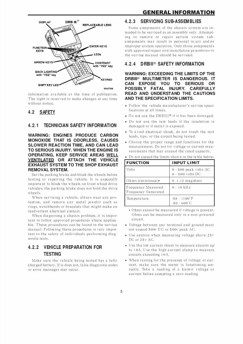
4.2.4 DRBI II SAFETY INFORMATION
WARNING: EXCEEDING THE LIMITS OF THEDRBIII MULTIMETER IS DANGEROUS. ITCAN EXPOSE YOU TO SERIOUS ORPOSSIBLY FATAL INJURY. CAREFULLYREAD AND UNDERSTAND THE CAUTIONSAND THE SPECIFICATION LIMITS.
• Follow the vehicle ma nufacturer’s service speci-
fications at all t imes.
• D o n ot u se t h e D RB I I I
i f i t h a s b ee n d a m a g e d.• D o n ot u s e t h e t e st l ea d s i f t h e i n su la t i on i s
dam aged or if meta l is exposed.
• To a void electrical shock, do not touch the test
leads, t ips, or t he circuit being t ested.
• C h o o se t h e p r o p e r r a n g e a n d f u n ct io n s f o r t h e
measurement. Do not try voltage or current m ea-
surements that may exceed the rated capacity.
• Do not exceed the limits show n in the ta ble below:
FUNCTION INPUT LIMIT
Volt s 0 - 500 pea k volt s AC
0 - 500 volts DC
O h m s (r es is t a n ce )* 0 -1. 12 m eg oh m s
Frequency Measured
Frequency Generated
0 - 10 kH z
Tem pera ture -58 - 1100° F
-50 - 600° C
* Ohms cannot be mea sured if volta ge is present.
Ohms can be measured only in a non-powered
circuit.
• Volt a g e b e t w e en a n y t e r m in a l a n d g r ou n d m u st
not exceed 500v D C or 500v pea k AC.
• Use caution when measuring voltage above 25v
DC or 25v AC.
• Use th e low current shunt to measure circuits up
t o 10A. U se t h e h ig h cu r r en t cla m p t o m e a su r e
circuits exceeding 10A.
• When t esting for t he presence of voltage or cur-
r e n t , m a k e su r e t h e m e t er is f u n ct ion in g cor -
r ect l y. Ta k e a r ea d i n g of a k n ow n v ol t a g e o r
current before a ccepting a zero reading.
5
GENERAL INFORMATION

7/21/2019 2005 RS Chassis
http://slidepdf.com/reader/full/2005-rs-chassis 10/86
• When measuring current, connect the meter in
series with the load.
• Disconnect the live test lead before disconnecting
the common test lead.
• Wh en u sin g t h e m et er f un ct ion , keep t h e
D R B I I I a w a y f r o m sp a r k p lu g o r co il w ir e s t o
avoid measuring error from outside interference.
4.3 WARNINGS
4. 3. 1 VEHICLE DAMAGE WARNINGS
Before disconnecting any control module, make
su r e t h e ig n it ion is ‘‘of f ’’. F a i lu r e t o d o so cou ld
damage the module.
When testing voltage or continuity at any control
module, use the terminal side (not th e w ire end) of
t h e con n e ct o r. D o n o t p r ob e a w ir e t h r o ug h t h e
insulation, this will dama ge it a nd eventua lly cause
it to fail because of corrosion.
B e careful when performing electrical t ests so a st o p r even t a ccid en t a l sh or t in g of t e r m in a ls . S u ch
mista kes can dam age fuses or components. Also, a
second code could be set , making diagnosis of the
original problem more difficult.
4. 3. 2 ROAD TESTING A COMPLAINT
VEHICLE
Some complaints w ill require a t est drive as par t
of the repair verifica tion procedure. The purpose of
t h e t e st d r ive is t o t r y t o d u p lica t e t h e d ia g n o st ic
code or sympt om condition.
WARNING: BEFORE ROAD TESTING AVEHICLE, BE SURE THAT ALLCOMPONENTS ARE REASSEMBLED.DURING THE TEST DRIVE, DO NOT TRY TOREAD THE DRB SCREEN WHILE IN MOTION.DO NOT HANG THE DRBIII FROM THEREAR VIEW MIRROR OR OPERATE ITYOURSELF. HAVE AN ASSISTANTAVAILABLE TO OPERATE THE DRBIII.
4.4 DIAGNOSIS
1. Your diagnostic test procedure must begin with a
th orough visua l inspection of the syst em in ques-
tion for da ma ged components or disconnected
co n n e ct o r s. F o r A B S t h e b r a k e la m p s m u st b e
operational prior to continuing.
2. C o n n ect t h e D RB I I I to t he da ta link connector,
which is located under th e dash to the left of the
st e er in g colu m n . I f t h e D RB I I I does n ot power
up, check the power a nd ground supplies t o the
connector.
3. Turn t he ignit ion on. Select the syst em in q ues-
t ion . I f t h e D R B I I I d ispla y s “N o Re spon se”
condition you must diagnose that f irst .
4. Rea d an d record a ll diagnostic trouble codes. For
ABS if the “Valve Power Feed Circuit” diagnostic
trouble code is present, it must be repaired prior
to addressing a ny other DTC’s. If a ny a ddit iona l
DTC’s are present, proceed to the appropriate
test by locating t he ma tching test in the Ta ble ofContents and begin to diagnose the symptom.
5. For AB S if there are n o diagnostic trouble codes
present, identify the customer complaint. Select
“Inputs/Outputs” a nd rea d t he brake sw itch in-
put as you press and release the brake pedal. I f
the display does not ma tch the sta te of the pedal,
perform the proper test by locating the matching
test in the Table of Contents a nd begin to diag-
nose the symptom. If a problem exists with the
y el low “ AB S ” w a r n in g i nd ica t or or t h e r ed
“Brake” indicator exists, refer to the proper tests
b y l oca t i n g t h e m a t c h in g t e st i n t h e Ta b l e o fC o n t e n t s a n d b e g in t o d ia g n o se t h e sy m p t o m .
Re a d t h e t r a ct io n co n t r o l sw it ch in p u t a s y o u
press and release the switch. If the display does
not ma tch the st at e of the indicator perform t he
proper test by locating the matching test in the
Ta b l e o f C on t en t s a n d b eg in t o d ia g n os e t h e
symptom.
6. If no other problems a re found, it will be neces-
sa r y t o r o a d t e st t h e ve h icle. P e r for m se ve r a l
a nt ilock st ops from a bove 50 Km /h (30 mph) a nd
t h en r ep ea t s t ep 4. I f a n y d i a g nos t ic t r ou b le
cod e s a r e p r ese n t , p r ocee d t o t h e a p p r op r ia t e
t e st .
7. The following conditions should be considered
“NORMAL” operation, a nd no repairs should be
at tempted to correct them.
– B r a k e ped a l f eed ba c k d ur in g a n AB S s t op
(clicking, vibra ting).
– Clicking, groaning or buzzing a t 25 Km/h (15
mph) or 40 K m/h (24 mph ) (driv e off self tes t).
– G r o a n in g n o ise d u r in g a n A B S st op .
– S l ig h t b r a k e p e d a l d r o p a n d p op n o ise w h e n
ignit ion is init ially t urned on.
– B r a k e p ed a l r a t ch et in g d ow n a t t h e e n d of a nABS stop.
8. If th e complaint is AB S “cycling” at the end of a
s t op a t low s peed s, it m a y b e c a us ed b y a
ma rginal wheel speed sensor signal. The sensor
a ir g a p , t o n e w h e el con d it ion , a n d /or b r a k e s
hanging up are possible causes of this condition.
9. Af t er a r oa d t e st i n w h i ch n o p r ob le ms w e r e
found, refer to any Technical Service B ulletins
t h a t m a y a p ply.
6
GENERAL INFORMATION

7/21/2019 2005 RS Chassis
http://slidepdf.com/reader/full/2005-rs-chassis 11/86
5.0 REQUIRED TOOLS ANDEQUIPMENT
D R B I I I (dia gnostic r ead-out box)
jumper wires
ohmmeter
voltmeter
test light
6.0 GLOSSARY OF TERMS
ABS an tilock brake system
CAB cont roller an tilock bra ke
DC direct current
DLC dat a link connector
DRB dia gnostic rea d-out box
DTC diagnostic test code
EVBP electr onic va ria ble bra ke proportion-
in g
HCU hydra ulic control unit
IC U integrat ed control unit
IPM integrat ed power module
J BL K junction block
PCI program ma ble communication inter-
face
P/M pump motor
WSS wh eel speed sensor
7
GENERAL INFORMATION

7/21/2019 2005 RS Chassis
http://slidepdf.com/reader/full/2005-rs-chassis 12/86
NOTES
8
7/21/2019 2005 RS Chassis
http://slidepdf.com/reader/full/2005-rs-chassis 13/86
7.0
DIAGNOSTIC INFORMATION AND
PROCEDURES
9
7/21/2019 2005 RS Chassis
http://slidepdf.com/reader/full/2005-rs-chassis 14/86
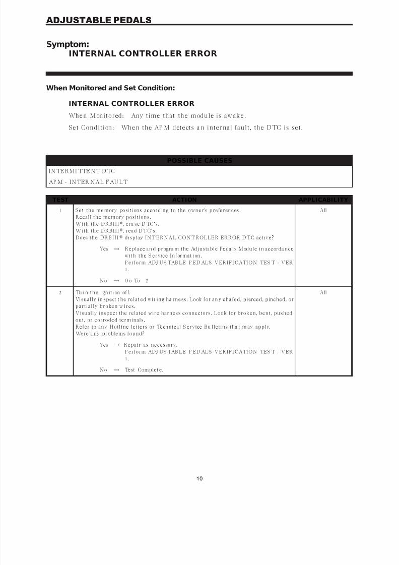
Symptom:INTERNAL CONTROLLER ERROR
When Monitored and Set Condition:
INTERNAL CONTROLLER ERROR
When Monitored: Any t ime that the module is aw ake.
Set Condit ion: When the AP M detects a n internal fault , the DTC is set .
POSSIBLE CAUSES
IN TE RMI TTE NT D TC
AP M - INTER NAL FAU LT
TEST ACTION APPLICABILITY
1 Set t h e memor y posit ion s a ccor din g t o t h e ow n er ’s p r efer en ces .
Recall the memory positions.
W it h t h e DR B I I I, era se D TC’s.
W it h t h e DR B I I I, read DTC’s.
D o es t h e D R B I I I display INTERNAL CONTROLLER ERROR DTC active?
All
Yes → Replace an d progra m the Adjustable Peda ls Module in accorda nce
w it h t h e S er v ice I n for ma t ion .
P erform ADJ US TAB LE P ED ALS VERIFI CATION TES T - VER
1.
No → G o To 2
2 Tu r n t h e i gn it i on of f.
Visually in spect t he relat ed wir ing ha rness. Look for an y cha fed, pierced, pinched, or
p a r t ia lly br oken w ir es.
Visually inspect the related wire harness connectors. Look for broken, bent, pushed
out, or corroded terminals.
Refer to any Hotline letters or Technical S ervice Bu lletins tha t m ay apply.
Were a ny problems found?
All
Yes → Repair as necessary.
P erform ADJ US TAB LE P ED ALS VERIFI CATION TES T - VER
1.
No → Test Complet e.
10
ADJUSTABLE PEDALS

7/21/2019 2005 RS Chassis
http://slidepdf.com/reader/full/2005-rs-chassis 15/86
Symptom:PEDAL SENSOR OPEN/SHORTED TO GROUND
When Monitored and Set Condition:
PEDAL SENSOR OPEN/SHORTED TO GROUND
When Monitored: Continuously.
Set Condit ion: When the Adjusta ble Pedals Module detects a ground condit ion on t he
Adjusta ble P edal Sensor Signa l c ircuit .
POSSIBLE CAUSES
IN TE RMI TTE NT D TC
AD J U S TAB L E P ED A L S S E N S O R F EE D C I RC U I T O PE N
AD J U S TAB L E P ED A L S S EN S O R RETU RN C I RC U I T O PE N
AD J U S TAB L E P ED A L S S E N S O R S I G N A L C I RC U I T O PE N
ADJ US TAB LE P ED ALS SE NSOR FAULT
AP M - INTER NAL FAU LT
TEST ACTION APPLICABILITY
1 Wit h t he D RB I II, era se D TC’s.
W it h t h e DR B I I I, read DTC’s.
D o es t h e D R B I I I dis pla y P E DA L SE NS OR OP E N/SH OR TE D TO G R OU ND DTC
active?
All
Yes → G o To 2
No → G o To 8
2 Tu r n t h e i gn it i on of f.
E n s u r e t h e Adju s t a ble P eda ls S en s or is fu lly s ea t ed a n d locked.
Turn the ignition on.
W it h t h e DR B I I I, read the active DTC’s.
D o es t h e D R B I I I dis pla y P E DA L SE NS OR OP E N/SH OR TE D TO G R OU ND DTC
active?
All
Yes → G o To 3
No → G o To 8
3 Tu r n t h e i gn it i on of f.
Disconnect the Adjustable Pedals Sensor harness connector.
Turn the ignition on.
M ea s u r e t h e v olt a ge bet w een t h e A dju s t a ble P eda ls Sen s or Feed cir cu it a n d t h e
Adjustable Pedals Sensor Return circuit .
I s t h e v olt a ge bet w een 4 a n d 5. 2 v olt s ?
All
Yes → G o To 4
No → G o To 6
11
ADJUSTABLE PEDALS

7/21/2019 2005 RS Chassis
http://slidepdf.com/reader/full/2005-rs-chassis 16/86
TEST ACTION APPLICABILITY
4 Tu r n t h e i gn it i on of f.
Disconnect the Adjustable Pedals Sensor harness connector.
Disconnect the Adjustable Pedals Module harness connector.
M ea s u r e t h e r es is t a n ce of t h e A dju s t a ble P eda ls S en s or Sign a l cir cu it bet w een t h eAdjustable Pedals Sensor connector and the Adjustable Pedals Module connector.
Is the resistance below 1.0 ohm?
All
Yes → G o To 5
No → Repair the Adjustable Peda ls Sensor Signal circuit for an open.
P erform ADJ US TAB LE P ED ALS VERIFI CATION TES T - VER
1.
5 Tu r n t h e i gn it i on of f.
Disconnect the Adjustable Pedals Sensor harness connector.
Measure the resistance between the Adjustable Pedals Sensor Signal circuit and the
A dju s t a ble P eda ls Sen s or R et u r n cir cu it a t t h e A dju s t a ble P eda ls Sen s or h a r n es s
connector.
Is the resistance below 100.0 ohms?
All
Yes → Replace an d progra m the Adjustable Peda ls Module in accorda nce
w it h t h e S er v ice I n for ma t ion . .
P erform ADJ US TAB LE P ED ALS VERIFI CATION TES T - VER
1.
No → R e pl a ce t h e A dju s t a b l e P e d a l s S e n so r i n a c cor d a n c e w i t h t h e
Service Information.
P erform ADJ US TAB LE P ED ALS VERIFI CATION TES T - VER
1.
6 Tu r n t h e i gn it i on of f.
Disconnect the Adjustable Pedals Sensor harness connector.
Disconnect the Adjustable Pedals Module harness connector.
M ea s u r e t h e r es is t a n ce of t h e A dju s t a ble P eda ls Sen s or Feed cir cu it bet w een t h eAdjustable Pedals Sensor connector and the Adjustable Pedals Module connector.
Is the resistance below 1.0 ohm?
All
Yes → G o To 7
No → Repair the Adjustable P edals S ensor Feed circuit for an open.
P erform ADJ US TAB LE P ED ALS VERIFI CATION TES T - VER
1.
7 Tu r n t h e i gn it i on of f.
Disconnect the Adjustable Pedals Sensor harness connector.
Disconnect the Adjustable Pedals Module harness connector.
M ea s u r e t h e r es is t a n ce of t h e A dju s t a ble P eda ls S en s or R et u r n cir cu it bet w een t h e
Adjustable Pedals Sensor connector and the Adjustable Pedals Module connector.
Is the resistance below 1.0 ohm?
All
Yes → Replace an d progra m the Adjustable Peda ls Module in accorda nce
w it h t h e S er v ice I n for ma t ion . .
P erform ADJ US TAB LE P ED ALS VERIFI CATION TES T - VER
1.
No → Repair the Adjustable P edals S ensor Return circuit for a n open.
P erform ADJ US TAB LE P ED ALS VERIFI CATION TES T - VER
1.
12
ADJUSTABLE PEDALS
PEDAL SENSOR OPEN/SHORTED TO GROUND — Continued

7/21/2019 2005 RS Chassis
http://slidepdf.com/reader/full/2005-rs-chassis 17/86
TEST ACTION APPLICABILITY
8 Tu r n t h e i gn it i on of f.
Visually in spect t he relat ed wir ing ha rness. Look for an y cha fed, pierced, pinched, or
p a r t ia lly br oken w ir es.
Visually inspect the related wire harness connectors. Look for broken, bent, pushedout, or corroded terminals.
Refer to any Hotline letters or Technical S ervice Bulletins t ha t m ay apply.
Were a ny problems found?
All
Yes → Repair as necessary.
P erform ADJ US TAB LE P ED ALS VERIFI CATION TES T - VER
1.
No → Test Complet e.
13
ADJUSTABLE PEDALS
PEDAL SENSOR OPEN/SHORTED TO GROUND — Continued
7/21/2019 2005 RS Chassis
http://slidepdf.com/reader/full/2005-rs-chassis 18/86
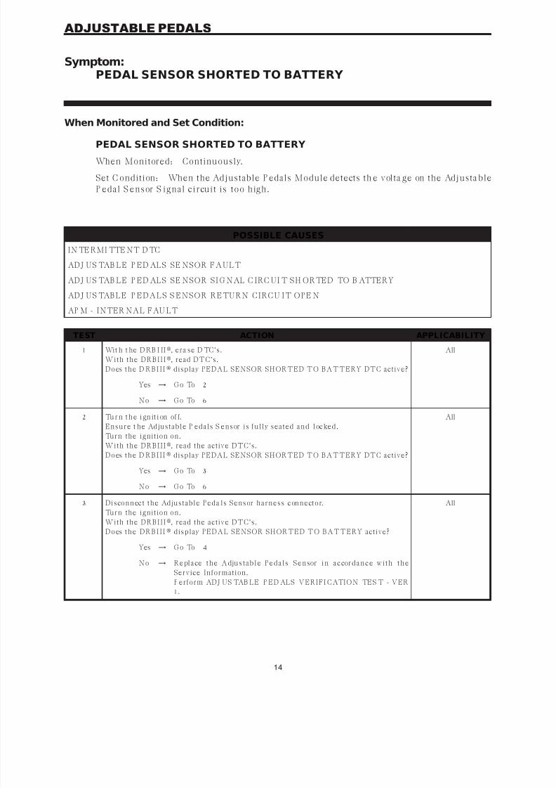
Symptom:PEDAL SENSOR SHORTED TO BATTERY
When Monitored and Set Condition:
PEDAL SENSOR SHORTED TO BATTERY
When Monitored: Continuously.
Set C ondition: When the Adjustable P edals Module detects th e volta ge on the Adjusta ble
P edal S ensor S ignal c ircuit is too high.
POSSIBLE CAUSES
IN TE RMI TTE NT D TC
ADJ US TAB LE P ED ALS SE NSOR FAULT
ADJ US TAB LE P ED ALS SE NSOR SI G NAL C IRC UI T SH ORTED TO B ATTERY
AD J U S TAB L E P ED A L S S EN S O R RETU RN C I RC U I T O PE N
AP M - INTER NAL FAU LT
TEST ACTION APPLICABILITY
1 Wit h t he D RB I II, era se D TC’s.
W it h t h e DR B I I I, read DTC’s.
D o es t h e D R B I I I display PEDAL SENSOR SHORTED TO BATTERY DTC active?
All
Yes → G o To 2
No → G o To 6
2 Tu r n t h e i gn it i on of f.
E n s u r e t h e Adju s t a ble P eda ls S en s or is fu lly s ea t ed a n d locked.
Turn the ignition on.
W it h t h e DR B I I I, read the active DTC’s.
D o es t h e D R B I I I display PEDAL SENSOR SHORTED TO BATTERY DTC active?
All
Yes → G o To 3
No → G o To 6
3 Dis con n ect t h e Adju s t a ble P eda ls Sen s or h a r n es s con n ect or.
Turn the ignition on.
W it h t h e DR B I I I, read the active DTC’s.
D o es t h e D R B I I I
display PEDAL SENSOR SHORTED TO BATTERY active?
All
Yes → G o To 4
No → R e pl a ce t h e A dju s t a b l e P e d a l s S e n sor i n a c cor d a n c e w i t h t h e
Service Information.
P erform ADJ US TAB LE P ED ALS VERIFI CATION TES T - VER
1.
14
ADJUSTABLE PEDALS

7/21/2019 2005 RS Chassis
http://slidepdf.com/reader/full/2005-rs-chassis 19/86
TEST ACTION APPLICABILITY
4 Tu r n t h e i gn it i on of f.
Disconnect the Adjustable Pedals Sensor harness connector.
Disconnect the Adjustable Pedals Module harness connector.
Note: Check connector - Clean/repair as necessary.Turn the ignition on.
M ea s u r e t h e v olt a ge of t h e Adjus t a ble P eda ls S en s or Sign a l cir cu it .
I s t h er e a n y v olt a ge p r es en t ?
All
Yes → R epa ir t h e Adju s t a ble P eda ls Sen s or Sign a l cir cu it for a s h or t t o
voltage.
P erform ADJ US TAB LE P ED ALS VERIFI CATION TES T - VER
1.
No → G o To 5
5 Tu r n t h e i gn it i on of f.
Disconnect the Adjustable Pedals Sensor harness connector.
Disconnect the Adjustable Pedals Module harness connector.
Note: Check connector - Clean/repair as necessary.M ea s u r e t h e r es is t a n ce of t h e A dju s t a ble P eda ls S en s or R et u r n cir cu it bet w een t h e
Adjustable Pedals Sensor connector and the APM connector.
Is the resistance below 1 ohm?
All
Yes → Replace an d progra m the Adjustable Peda ls Module in accorda nce
w it h t h e S er v ice I n for ma t ion . .
P erform ADJ US TAB LE P ED ALS VERIFI CATION TES T - VER
1.
No → Repair the Adjustable P edals Sensor Return circuit for an open.
P erform ADJ US TAB LE P ED ALS VERIFI CATION TES T - VER
1.
6 Tu r n t h e i gn it i on of f.
Visually inspect th e relat ed w iring ha rness. Look for an y cha fed, pierced, pinched, orp a r t ia lly br oken w ir es.
Visually inspect the related wire harness connectors. Look for broken, bent, pushed
out, or corroded terminals.
M ov e t h e p e da l s a l l t h e w a y f o r w a r d a n d r e a r w a r d t o s ee i f t h e D TC i s r e la t e d t o
position.
Refer to any Hotline letters or Technical S ervice Bu lletins tha t m ay apply.
Were a ny problems found?
All
Yes → Repair as necessary.
P erform ADJ US TAB LE P ED ALS VERIFI CATION TES T - VER
1.
No → Test Complet e.
15
ADJUSTABLE PEDALS
PEDAL SENSOR SHORTED TO BATTERY — Continued
7/21/2019 2005 RS Chassis
http://slidepdf.com/reader/full/2005-rs-chassis 20/86
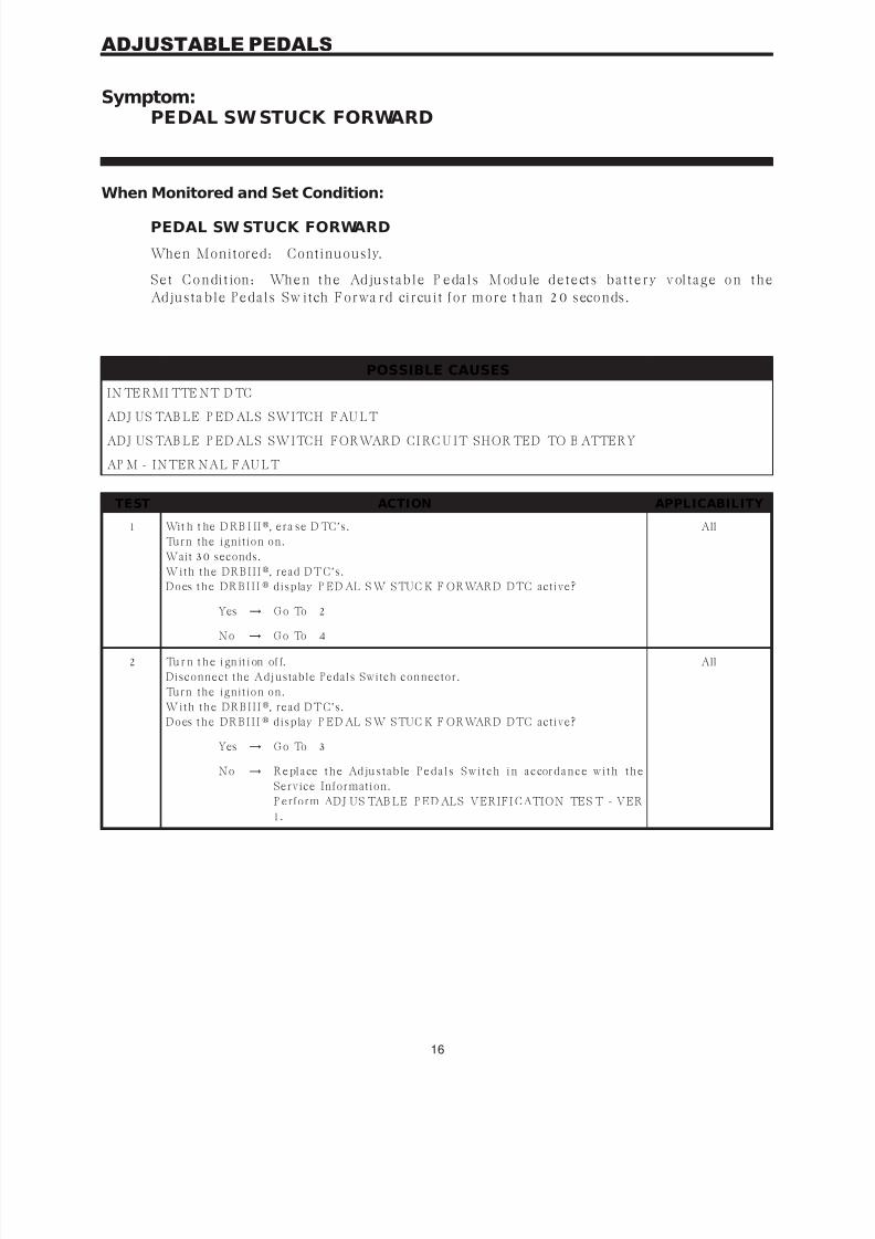
Symptom:PEDAL SW STUCK FORWARD
When Monitored and Set Condition:
PEDAL SW STUCK FORWARD
When Monitored: Continuously.
S e t C o n di t ion : Wh e n t h e Ad ju s t a b l e P e da l s M od u le d e t e ct s b a t t e r y v ol t a g e o n t h e
Adjusta ble Pedals Sw itch Forwa rd circuit for more t han 20 seconds.
POSSIBLE CAUSES
IN TE RMI TTE NT D TC
ADJ US TAB LE P ED ALS SWITCH FAU LT
ADJ US TAB LE P ED ALS SWITCH FORWARD CI RC U IT SHOR TED TO B ATTERY
AP M - INTER NAL FAU LT
TEST ACTION APPLICABILITY
1 Wit h t he D RB I II, era se D TC’s.
Turn the ignition on.
Wait 30 seconds.
W it h t h e DR B I I I, read DTC’s.
D o es t h e D R B I I I display P ED AL S W STUC K F ORWARD DTC active?
All
Yes → G o To 2
No → G o To 4
2 Tu r n t h e i gn it i on of f.
Disconnect the Adjustable Pedals Switch connector.
Turn the ignition on.
W it h t h e DR B I I I, read DTC’s.
D o es t h e D R B I I I display P ED AL S W STUC K F ORWARD DTC active?
All
Yes → G o To 3
No → R e pl a ce t h e Ad ju s t a b le P e d a l s S w i t c h i n a c cor d a n c e w i t h t h e
Service Information.
P erform ADJ US TAB LE P ED ALS VERIFI CATION TES T - VER
1.
16
ADJUSTABLE PEDALS

7/21/2019 2005 RS Chassis
http://slidepdf.com/reader/full/2005-rs-chassis 21/86
TEST ACTION APPLICABILITY
3 Tu r n t h e i gn it i on of f.
Disconnect the Adjustable Pedals Module harness connector.
Disconnect the Adjustable Pedals Switch connector.
Turn the ignition ON.M ea s u r e t h e v olt a ge of t h e Adjus t a ble P eda ls Sw it ch For w a r d cir cu it .
I s t h er e a n y v olt a ge p r es en t ?
All
Yes → Repair the Adjustable Peda ls Switch Forwa rd circuit for a short to
voltage.
P erform ADJ US TAB LE P ED ALS VERIFI CATION TES T - VER
1.
No → Replace an d progra m the Adjustable Peda ls Module in accorda nce
w it h t h e S er v ice I n for ma t ion .
P erform ADJ US TAB LE P ED ALS VERIFI CATION TES T - VER
1.
4 Tu r n t h e i gn it i on of f.
Visually in spect t he relat ed w iring ha rness. Look for an y cha fed, pierced, pinched, orp a r t ia lly br oken w ir es.
Visually inspect the related wire harness connectors. Look for broken, bent, pushed
out, or corroded terminals.
Refer to any Hotline letters or Technical S ervice Bu lletins tha t m ay apply.
Were a ny problems found?
All
Yes → Repair as necessary.
P erform ADJ US TAB LE P ED ALS VERIFI CATION TES T - VER
1.
No → Test Complet e.
17
ADJUSTABLE PEDALS
PEDAL SW STUCK FORWARD — Continued

7/21/2019 2005 RS Chassis
http://slidepdf.com/reader/full/2005-rs-chassis 22/86
Symptom:PEDAL SW STUCK REARWARD
When Monitored and Set Condition:
PEDAL SW STUCK REARWARD
When Monitored: Continuously.
S e t C o n di t ion : Wh e n t h e Ad ju s t a b l e P e da l s M od u le d e t e ct s b a t t e r y v ol t a g e o n t h e
Adjusta ble Pedals Sw itch R earw ar d circuit for more tha n 20 seconds.
POSSIBLE CAUSES
IN TE RMI TTE NT D TC
ADJ US TAB LE P ED ALS SWITCH FAU LT
ADJ US TAB LE P ED ALS SWITCH RE ARWARD CI RC U IT SHOR TED TO B ATTERY
AP M - INTER NAL FAU LT
TEST ACTION APPLICABILITY
1 Wit h t he D RB I II, era se D TC’s.
Turn the ignition on.
Wait 30 seconds.
W it h t h e DR B I I I, read DTC’s.
D o es t h e D R B I I I display P ED AL S W STUC K R EARWARD DTC a ctive?
All
Yes → G o To 2
No → G o To 4
2 Tu r n t h e i gn it i on of f.
Disconnect the Adjustable Pedals Switch connector.
Turn the ignition on.
W it h t h e DR B I I I, read DTC’s.
D o es t h e D R B I I I display P ED AL S W STUC K R EARWARD DTC a ctive?
All
Yes → G o To 3
No → R e pl a ce t h e Ad ju s t a b le P e d a l s S w i t c h i n a c cor d a n c e w i t h t h e
Service Information.
P erform ADJ US TAB LE P ED ALS VERIFI CATION TES T - VER
1.
18
ADJUSTABLE PEDALS

7/21/2019 2005 RS Chassis
http://slidepdf.com/reader/full/2005-rs-chassis 23/86
TEST ACTION APPLICABILITY
3 Tu r n t h e i gn it i on of f.
Disconnect the Adjustable Pedals Module harness connector.
Disconnect the Adjustable Pedals Switch connector.
Turn the ignition ON.M ea s u r e t h e v olt a ge of t h e Adjus t a ble P eda ls Sw it ch R ea r w a r d cir cu it .
I s t h er e a n y v olt a ge p r es en t ?
All
Yes → R epa ir t h e Adju s t a ble P eda ls S w it ch R ea r w a r d cir cu it for a s h or t
to voltage.
P erform ADJ US TAB LE P ED ALS VERIFI CATION TES T - VER
1.
No → Replace an d progra m the Adjustable Peda ls Module in accorda nce
w it h t h e S er v ice I n for ma t ion .
P erform ADJ US TAB LE P ED ALS VERIFI CATION TES T - VER
1.
4 Tu r n t h e i gn it i on of f.
Visually in spect t he relat ed w iring ha rness. Look for an y cha fed, pierced, pinched, orp a r t ia lly br oken w ir es.
Visually inspect the related wire harness connectors. Look for broken, bent, pushed
out, or corroded terminals.
Refer to any Hotline letters or Technical S ervice Bu lletins tha t m ay apply.
Were a ny problems found?
All
Yes → Repair as necessary.
P erform ADJ US TAB LE P ED ALS VERIFI CATION TES T - VER
1.
No → Test Complet e.
19
ADJUSTABLE PEDALS
PEDAL SW STUCK REARWARD — Continued
7/21/2019 2005 RS Chassis
http://slidepdf.com/reader/full/2005-rs-chassis 24/86
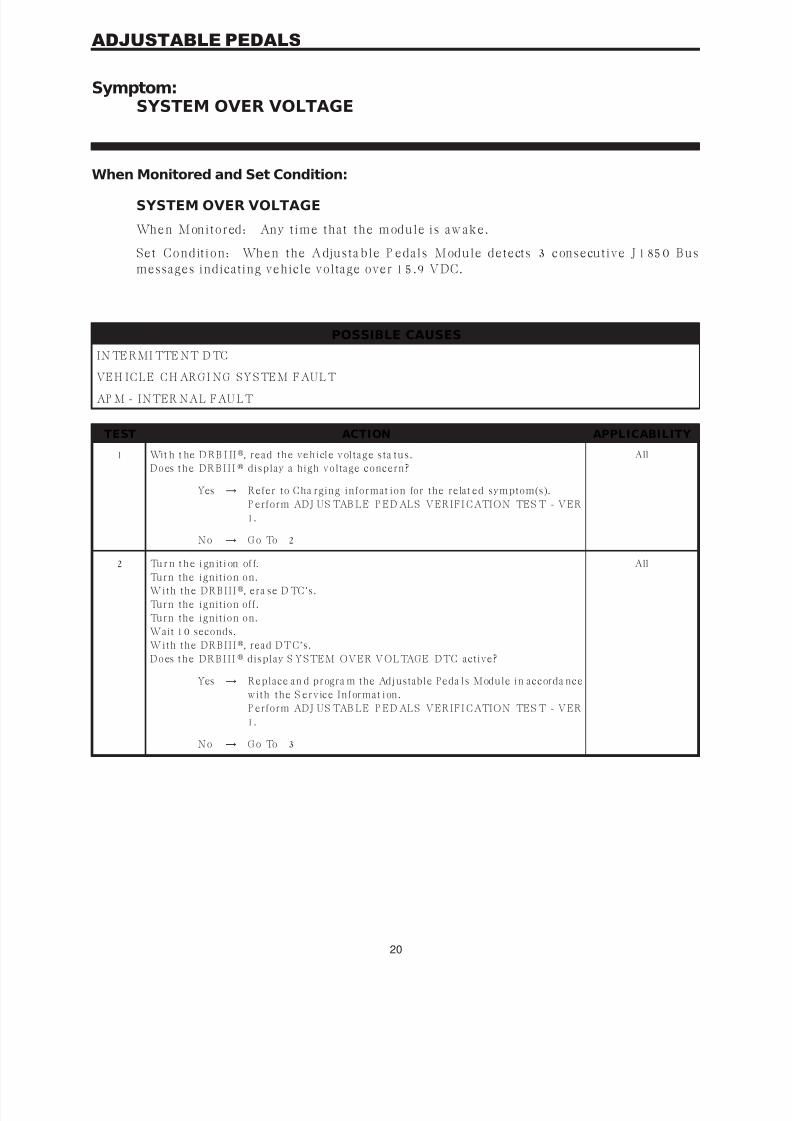
Symptom:SYSTEM OVER VOLTAGE
When Monitored and Set Condition:
SYSTEM OVER VOLTAGE
When Monitored: Any t ime that the module is aw ake.
Set Condit ion: When the Adjusta ble P edals Module detects 3 consecutive J 1850 Bus
messages indicating vehicle voltage over 15.9 VDC.
POSSIBLE CAUSES
IN TE RMI TTE NT D TC
VEH I C L E C H ARG I N G S YS TEM F AU L T
AP M - INTER NAL FAU LT
TEST ACTION APPLICABILITY
1 Wit h t he D RB I II, r ea d t h e v eh icle v olt a ge s t a t u s .
D o es t h e D R B I I I display a high voltage concern?
All
Yes → Refer to Cha rging informat ion for the relat ed symptom(s).
P erform ADJ US TAB LE P ED ALS VERIFI CATION TES T - VER
1.
No → G o To 2
2 Tu r n t h e i gn it i on of f.Turn the ignition on.
W it h t h e DR B I I I, era se D TC’s.
Turn the ignition off.
Turn the ignition on.
Wait 10 seconds.
W it h t h e DR B I I I, read DTC’s.
D o es t h e D R B I I I display S YSTEM OVER VOLTAGE DTC active?
All
Yes → Replace an d progra m the Adjustable Peda ls Module in accorda nce
w it h t h e S er v ice I n for ma t ion .
P erform ADJ US TAB LE P ED ALS VERIFI CATION TES T - VER
1.
No → G o To 3
20
ADJUSTABLE PEDALS

7/21/2019 2005 RS Chassis
http://slidepdf.com/reader/full/2005-rs-chassis 25/86
TEST ACTION APPLICABILITY
3 Tu r n t h e i gn it i on of f.
NOTE: Ensure the battery is fully charged.Visually in spect t he relat ed wir ing ha rness. Look for an y cha fed, pierced, pinched, or
p a r t ia lly br oken w ir es.Visually inspect the related wire harness connectors. Look for broken, bent, pushed
out, or corroded terminals.
Refer to any Hotline letters or Technical S ervice Bulletins t ha t m ay apply.
I n s pe ct t h e v eh i cl e f o r a f t e r m a r k et a c ce ss or i es t h a t m a y e xce ed t h e G e n e r a t or
Sys t em ou t p u t .
Were a ny problems found?
All
Yes → Repair as necessary.
P erform ADJ US TAB LE P ED ALS VERIFI CATION TES T - VER
1.
No → Test Complet e.
21
ADJUSTABLE PEDALS
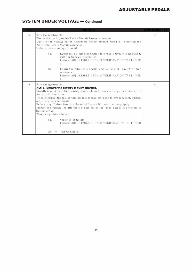
SYSTEM OVER VOLTAGE — Continued
7/21/2019 2005 RS Chassis
http://slidepdf.com/reader/full/2005-rs-chassis 26/86
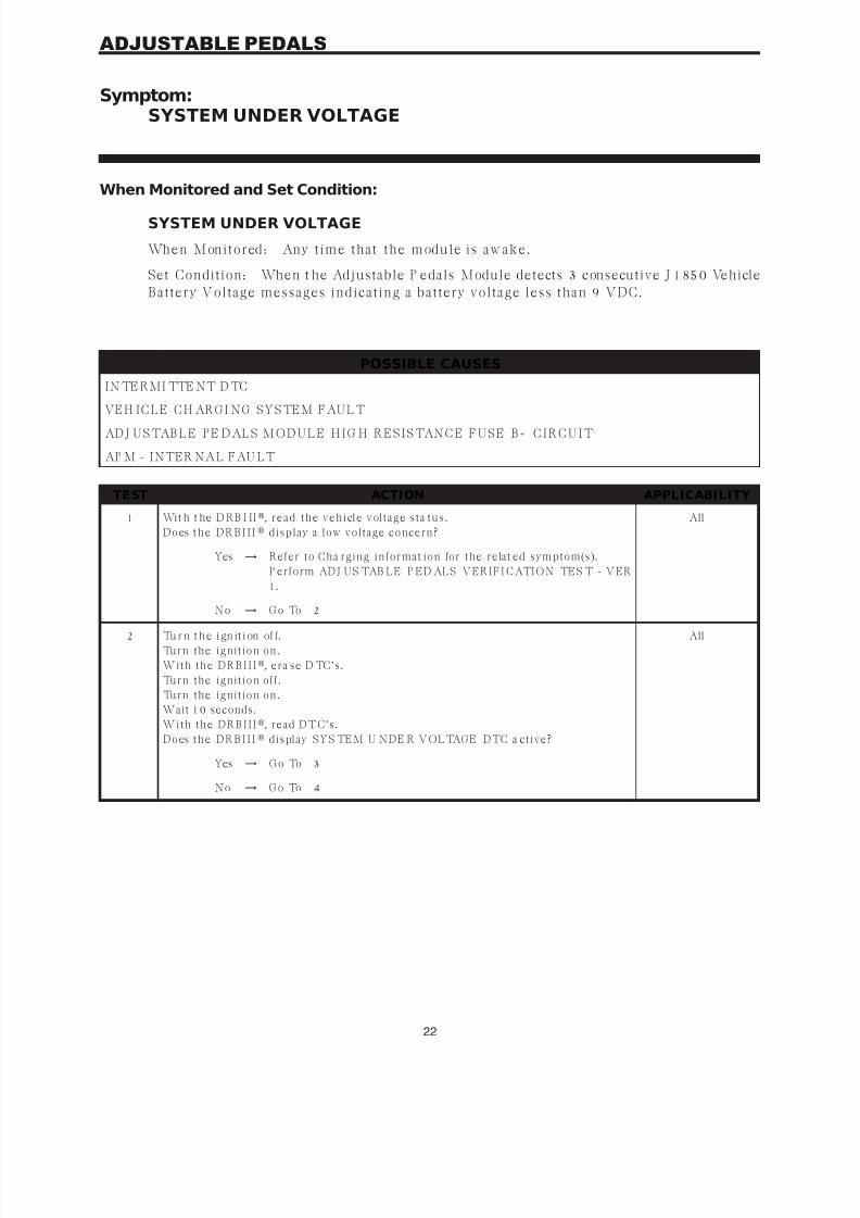
Symptom:SYSTEM UNDER VOLTAGE
When Monitored and Set Condition:
SYSTEM UNDER VOLTAGE
When Monitored: Any t ime that the module is aw ake.
Set Condition: When t he Adjustable P edals Module detects 3 consecutive J 1850 Vehicle
Battery V oltage messages indicat ing a bat tery voltage less than 9 V DC.
POSSIBLE CAUSES
IN TE RMI TTE NT D TC
VEH I C L E C H ARG I N G S YS TEM F AU L T
AD J U S TAB L E P E D AL S M O D U L E H I G H R E S I S TAN C E F U S E B + C I R C U I T
AP M - INTER NAL FAU LT
TEST ACTION APPLICABILITY
1 Wit h t he D RB I II, r ea d t h e v eh icle v olt a ge s t a t u s .
D o es t h e D R B I I I display a low voltage concern?
All
Yes → Refer to Cha rging informat ion for the relat ed symptom(s).
P erform ADJ US TAB LE P ED ALS VERIFI CATION TES T - VER
1.
No → G o To 2
2 Tu r n t h e i gn it i on of f.
Turn the ignition on.
W it h t h e DR B I I I, era se D TC’s.
Turn the ignition off.
Turn the ignition on.
Wait 10 seconds.
W it h t h e DR B I I I, read DTC’s.
D o es t h e D R B I I I display SYS TEM U NDE R VOLTAGE DTC a ctive?
All
Yes → G o To 3
No → G o To 4
22
ADJUSTABLE PEDALS
7/21/2019 2005 RS Chassis
http://slidepdf.com/reader/full/2005-rs-chassis 27/86
TEST ACTION APPLICABILITY
3 Tu r n t h e i gn it i on of f.
Disconnect the Adjustable Pedals Module harness connector.
M ea s u r e t h e v ol t a g e o f t h e A dju s t a b le P e d a l s M od u le F u s ed B + ci r cu i t i n t h e
Adjustable P edals Module connector.I s t h er e ba t t er y v olt a ge p r es en t ?
All
Yes → Replace an d progra m the Adjustable Peda ls Module in accorda nce
w it h t h e S er v ice I n for ma t ion .
P erform ADJ US TAB LE P ED ALS VERIFI CATION TES T - VER
1.
No → R epa ir t h e Adjus t a ble P eda ls M odu le Fu s ed B + cir cu it for h igh
resistance.
P erform ADJ US TAB LE P ED ALS VERIFI CATION TES T - VER
1.
4 Tu r n t h e i gn it i on of f.
NOTE: Ensure the battery is fully charged.
Visually in spect t he relat ed w iring ha rness. Look for an y cha fed, pierced, pinched, orp a r t ia lly br oken w ir es.
Visually inspect the related wire harness connectors. Look for broken, bent, pushed
out, or corroded terminals.
Refer to any Hotline letters or Technical S ervice Bu lletins tha t m ay apply.
I n s pe ct t h e v eh i cl e f o r a f t e r m a r k et a c ce ss or i es t h a t m a y e xce ed t h e G e n e r a t or
Sys t em ou t p u t .
Were a ny problems found?
All
Yes → Repair as necessary.
P erform ADJ US TAB LE P ED ALS VERIFI CATION TES T - VER
1.
No → Test Complet e.
23
ADJUSTABLE PEDALS
SYSTEM UNDER VOLTAGE — Continued
7/21/2019 2005 RS Chassis
http://slidepdf.com/reader/full/2005-rs-chassis 28/86
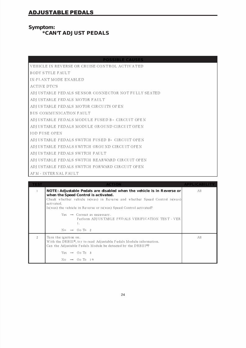
Symptom:*CAN’T ADJ UST PEDALS
POSSIBLE CAUSES
VEHICLE IN REVERSE OR CRUISE CONTROL ACTIVATED
B ODY S TYLE FAULT
IN-P LANT MODE ENABLE D
ACTIVE DTC’S
ADJ USTAB LE P ED ALS SE NSOR CONNE CTOR NOT FU LLY SEATED
ADJ USTAB LE P ED ALS MOTOR FAULT
ADJ US TAB LE P ED ALS MOTOR CIR CU ITS OP EN
B US COMMUNI CATION FAULT
AD J U S TAB L E P E D AL S M O D U L E F U S E D B + C I R C U I T OP E N
AD J U S TAB L E P ED A L S M O D U L E G R O U N D C I RC U I T O PE N
I O D F U S E O P E N
AD J U S TAB L E P ED A L S S WI TC H F U S ED B + C I RC U I T O PE N
AD J U S TAB L E P ED A L S S WI TC H G RO U N D C I RC U I T O PE N
ADJ US TAB LE P ED ALS SWITCH FAU LT
ADJ USTAB LE P ED ALS SWITCH REARWARD CIR CU IT OP EN
ADJ USTAB LE P ED ALS SWITCH FORWARD CIR CU IT OP EN
AP M - INTER NAL FAU LT
TEST ACTION APPLICABILITY
1 NOTE : Adjustable Pedals are disabled when the vehicle is in R everse orwhen the Speed Control is activated.C h e ck w h e t h er v eh i cl e i s(w a s ) i n R e ve r se a n d w h e t h er S p ee d C o n t r ol i s(w a s )
a ct iv a t ed.
Is(was) the vehicle in Reverse or is(was) Speed Control activated?
All
Yes → Correct as necessary.
P erform ADJ US TAB LE P ED ALS VERIFI CATION TES T - VER
1.
No → G o To 2
2 Tu rn t h e ig ni ti on on .
W it h t h e DR B I I I, t r y t o r ea d Adjus t a ble P eda ls M odu le in for ma t ion .
C a n t h e Adjus t a ble P eda ls M odu le be det ect ed by t h e D R B I I I?
All
Yes → G o To 3
No → G o To 1 9
24
ADJUSTABLE PEDALS

7/21/2019 2005 RS Chassis
http://slidepdf.com/reader/full/2005-rs-chassis 29/86
TEST ACTION APPLICABILITY
3 Tu rn t h e ig ni ti on on .
W it h t h e DR B I I I, go to Module Display.
D o es t h e D R B I I I disp la y R S B OD Y STYL E ?
All
Yes → G o To 4
No → R epla ce t h e Adju s t a ble P eda ls M odu le in a ccor da n ce w it h t h e
Service Information.
P erform ADJ US TAB LE P ED ALS VERIFI CATION TES T - VER
1.
4 Wit h t he D RB I II, r ea d t h e s t a t u s of t h e I n -P la n t M ode.
I s t h e I n -P la n t M ode E n a bled?
All
Yes → Dis a ble t h e I n -P la n t mode.
P erform ADJ US TAB LE P ED ALS VERIFI CATION TES T - VER
1.
No → G o To 5
5 Tu rn t h e i gn it ion on .
W it h t h e DR B I I I, era se D TC’s.
W it h t h e DR B I I I, read DTC’s.
D o es t h e D R B I I I display any DTC’s active?
All
Yes → Refer to symptom list for problems relat ed to the active DTC’s.
P erform ADJ US TAB LE P ED ALS VERIFI CATION TES T - VER
1.
No → G o To 6
6 Tu rn t h e i gn it ion on .
W it h t h e DR B I I I in I n p u t s /Ou t p u t s , r ea d t h e for w a r d a n d r ea r w a r d s w it ch es .
A ct u a t e t h e A dju s t a ble P eda ls Sw it ch in t h e for w a r d a n d r ea r w a r d p os it ion s .
D o e s t h e D R B I I I
display FORWARD/REARWARD SW C LOSE D wh en switch isa ct iv a t ed?
All
Yes → G o To 7
No → G o To 11
7 Tu rn t h e i gn it ion on .
W it h t h e DR B I I I, a c t u a t e t h e p e d a l f or w a r d a n d p ed a l r e a r w a r d .
Do the Adjustable Pedals move?
All
Yes → Replace an d progra m the Adjustable Peda ls Module in accorda nce
w it h t h e S er v ice I n for ma t ion .
P erform ADJ US TAB LE P ED ALS VERIFI CATION TES T - VER
1.
No → G o To 8
8 Tu r n t h e i gn it i on of f.
E n s u r e t h e Adju s t a ble P eda ls S en s or is fu lly s ea t ed a n d locked.
I n s pe ct Ad ju s t a b le P e d a l s M od u l e con n e ct o r a n d t h e Ad ju s t a b le P e d a l s M ot o r
connector.
Are the connectors FULLY seated and properly plugged in?
All
Yes → G o To 9
No → Repair as necessary.
P erform ADJ US TAB LE P ED ALS VERIFI CATION TES T - VER
1.
25
ADJUSTABLE PEDALS
*CAN’T ADJ UST PEDALS — Continued
7/21/2019 2005 RS Chassis
http://slidepdf.com/reader/full/2005-rs-chassis 30/86
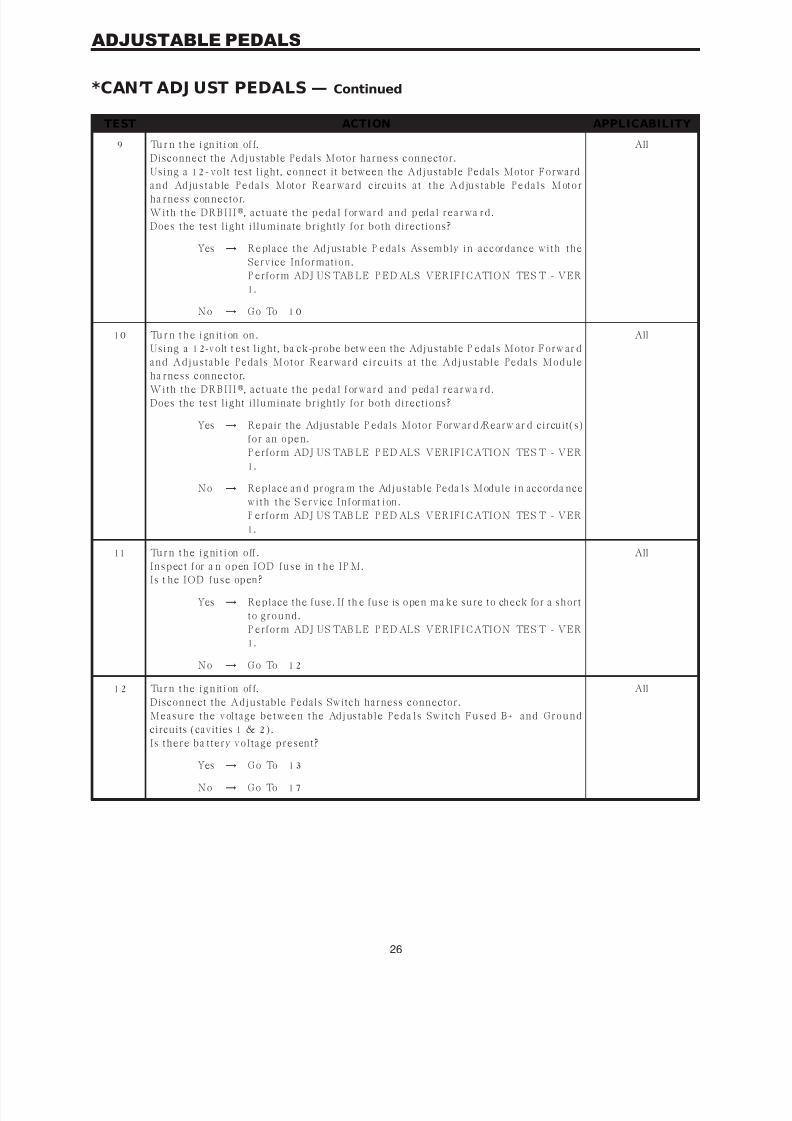
TEST ACTION APPLICABILITY
9 Tu r n t h e i gn it i on of f.
Disconnect the Adjustable Pedals Motor harness connector.
Using a 12-volt test light, connect it between the Adjustable Pedals Motor Forward
a n d Ad ju s t a b le P e d a l s M ot o r R e a r w a r d c ir cu i t s a t t h e A d ju s t a b le P e d a l s M ot o rha rness connector.
W it h t h e DR B I I I, a c t u a t e t h e p e d a l f or w a r d a n d p ed a l r e a r w a r d .
Does the test light illuminate brightly for both directions?
All
Yes → R epla ce t h e Adjus t a ble P eda ls As s embly in a ccor da n ce w it h t h e
Service Information.
P erform ADJ US TAB LE P ED ALS VERIFI CATION TES T - VER
1.
No → G o To 1 0
10 Tu r n t h e i gn it i on on .
Using a 12-volt t est light, ba ck-probe betw een the Adjustable P edals Motor Forw ar d
a n d A dju s t a ble P eda ls M ot or R ea r w a r d cir cu it s a t t h e A dju s t a ble P eda ls M odu le
ha rness connector.W it h t h e DR B I I I, a c t u a t e t h e p e d a l f or w a r d a n d p ed a l r e a r w a r d .
Does the test light illuminate brightly for both directions?
All
Yes → Repair the Adjustable P edals Motor Forw ar d/Rearw ar d circuit(s)
for an open.
P erform ADJ US TAB LE P ED ALS VERIFI CATION TES T - VER
1.
No → Replace an d progra m the Adjustable Peda ls Module in accorda nce
w it h t h e S er v ice I n for ma t ion .
P erform ADJ US TAB LE P ED ALS VERIFI CATION TES T - VER
1.
11 Tu r n t h e i g ni t i on o ff .
I n s p ect for a n op en I OD fu s e in t h e I P M .I s t h e I OD fu s e op en ?
All
Yes → Replace the fuse. If th e fuse is open ma ke sure to check for a short
t o gr ou n d.
P erform ADJ US TAB LE P ED ALS VERIFI CATION TES T - VER
1.
No → G o To 1 2
1 2 Tu r n t h e i g n it i on of f.
Disconnect the Adjustable Pedals Switch harness connector.
M ea s u r e t h e v olt a ge bet w een t h e Adjus t a ble P eda ls Sw it ch Fu s ed B + a n d G r ou n d
circuits (cavities 1 & 2).
I s t h er e ba t t er y v olt a ge p r es en t ?
All
Yes → G o To 1 3
No → G o To 1 7
26
ADJUSTABLE PEDALS
*CAN’T ADJ UST PEDALS — Continued
7/21/2019 2005 RS Chassis
http://slidepdf.com/reader/full/2005-rs-chassis 31/86
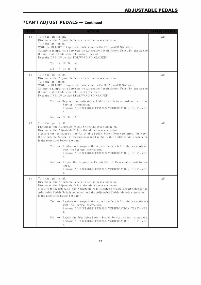
TEST ACTION APPLICABILITY
1 3 Tu r n t h e i g ni t i on o ff .
Disconnect the Adjustable Pedals Switch harness connector.
Turn the ignition on.
W it h t h e DR B I I I
in I nputs/Outputs, monitor t he F ORWARD SW sta te.C on n ect a jump er w ir e bet w een t h e Adjus t a ble P eda ls Sw it ch Fu s ed B + cir cu it a n d
t h e Adjus t a ble P eda ls Sw it ch For w a r d cir cu it .
D o es t h e D R B I I I display FORWARD SW CLOS ED ?
All
Yes → G o To 1 4
No → G o To 1 6
1 4 Tu r n t h e i g ni t i on o ff .
Disconnect the Adjustable Pedals Switch harness connector.
Turn the ignition on.
W it h t h e DR B I I I in Inputs/Outputs, monitor t he R EARWARD SW sta te.
C on n ect a ju mp er w ir e bet w een t h e Adjus t a ble P eda ls Sw it ch Fu s ed B + cir cu it a n d
t h e Adjus t a ble P eda ls Sw it ch R ea r w a r d cir cu it .
D o es t h e D R B I I I
display REARWARD SW CLOS ED ?
All
Yes → R e p l a c e t h e A d j u s t a b l e P e d a l s S w i t c h i n a c c o r d a n c e w i t h t h e
Service Information.
P erform ADJ US TAB LE P ED ALS VERIFI CATION TES T - VER
1.
No → G o To 1 5
1 5 Tu r n t h e i g ni t i on o ff .
Disconnect the Adjustable Pedals Switch harness connector.
Disconnect the Adjustable Pedals Module harness connector.
M ea s u r e t h e r es is t a n ce of t h e A dju s t a ble P eda ls Sw it ch R ea r w a r d cir cu it bet w een
the Adjustable P edals S wit ch connector an d t he Adjustable P edals Module connector.
Is the resistance below 1.0 ohm?
All
Yes → Replace an d progra m the Adjustable Peda ls Module in accorda nce
w it h t h e S er v ice I n for ma t ion .
P erform ADJ US TAB LE P ED ALS VERIFI CATION TES T - VER
1.
No → R e pa i r t h e Ad ju s t a b le P e d a l s S w i t ch R e a r w a r d ci r cu i t f o r a n
open.
P erform ADJ US TAB LE P ED ALS VERIFI CATION TES T - VER
1.
1 6 Tu r n t h e i g ni t i on o ff .
Disconnect the Adjustable Pedals Switch harness connector.
Disconnect the Adjustable Pedals Module harness connector.
Measure the resistance of the Adjustable Pedals Switch Forward circuit between the
Adjustable Pedals Switch connector and the Adjustable Pedals Module connector.Is the resistance below 1.0 ohm?
All
Yes → Replace an d progra m the Adjustable Peda ls Module in accorda nce
w it h t h e S er v ice I n for ma t ion .
P erform ADJ US TAB LE P ED ALS VERIFI CATION TES T - VER
1.
No → Repair the Adjustable Peda ls Swit ch Forw ar d circuit for an open.
P erform ADJ US TAB LE P ED ALS VERIFI CATION TES T - VER
1.
27
ADJUSTABLE PEDALS
*CAN’T ADJ UST PEDALS — Continued

7/21/2019 2005 RS Chassis
http://slidepdf.com/reader/full/2005-rs-chassis 32/86
TEST ACTION APPLICABILITY
1 7 Tu r n t h e i g ni t i on o ff .
Disconnect the Adjustable Pedals Switch harness connector.
Measure the voltage between Adjustable Pedals Switch Fused B+ circuit and vehicle
body ground.I s t h er e ba t t er y v olt a ge p r es en t ?
All
Yes → G o To 1 8
No → Repair the Adjustable Peda ls Switch Fused B+ circuit for an open.
P erform ADJ US TAB LE P ED ALS VERIFI CATION TES T - VER
1.
1 8 Tu r n t h e i g ni t i on o ff .
Disconnect the Adjustable Pedals Switch harness connector.
M ea s u r e t h e r es is t a n ce bet w een t h e A dju s t a ble P eda ls Sw it ch G r ou n d cir cu it a n d
vehicle body g round.
Is the resistance below 1.0 ohm?
All
Yes → R e p l a c e t h e A d j u s t a b l e P e d a l s S w i t c h i n a c c o r d a n c e w i t h t h e
Service Information.
P erform ADJ US TAB LE P ED ALS VERIFI CATION TES T - VER
1.
No → R epa ir t h e Adju s t a ble P eda ls Sw it ch G r ou n d cir cu it for a n open .
P erform ADJ US TAB LE P ED ALS VERIFI CATION TES T - VER
1.
1 9 Tu r n t h e i g n it i on o ff .
Disconnect the Adjustable Pedals Module harness connector.
Measure the volta ge between the Adjustable Peda ls Module Fused B+ circuit an d the
Ground circuit at the Adjustable Pedals Module harness connector.
I s t h er e ba t t er y v olt a ge p r es en t ?
All
Yes → R efer t o s ymp t om * NO R E SP ONSE FR OM ADJ U S TAB L E P E D-
ALS ASSEMBLY in the BODY COMMUNICATION category.
P erform ADJ US TAB LE P ED ALS VERIFI CATION TES T - VER
1.
No → G o To 2 0
2 0 Tu r n t h e i g n it i on of f.
Disconnect the Adjustable Pedals Module harness connector.
M ea s u r e t h e v olt a ge bet w een t h e Adjus t a ble P eda ls M odu le Fu s ed B + cir cu it a n d
vehicle body g round.
I s t h er e ba t t er y v olt a ge p r es en t ?
All
Yes → Repair th e Adjustable P edals Module Ground circuit for an open.
P erform ADJ US TAB LE P ED ALS VERIFI CATION TES T - VER
1.No → R e pa i r t h e Ad ju s t a b le P e d a ls M od u le F u s e d B + c ir cu i t f o r a n
open.
P erform ADJ US TAB LE P ED ALS VERIFI CATION TES T - VER
1.
28
ADJUSTABLE PEDALS
*CAN’T ADJ UST PEDALS — Continued
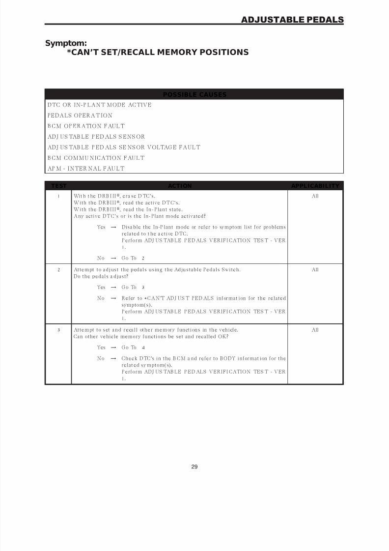
7/21/2019 2005 RS Chassis
http://slidepdf.com/reader/full/2005-rs-chassis 33/86
Symptom:*CAN’T SET/RECALL MEMORY POSITIONS
POSSIBLE CAUSES
DTC OR IN-P LANT MODE ACTIVE
PEDALS OPERATION
B CM OP ERATION FAULT
ADJ US TAB LE P ED ALS S ENS OR
ADJ US TAB LE P ED ALS SE NS OR VOLTAG E FAULT
B CM COMMU NICATION FAULT
AP M - INTER NAL FAU LT
TEST ACTION APPLICABILITY
1 Wit h t he D RB I II, era se D TC’s.
W it h t h e DR B I I I, read the active DTC’s.
W it h t h e DR B I I I, r ea d t h e I n -P la n t s t a t e.
Any active DTC’s or is the In-Plant mode activated?
All
Yes → Disa ble the In-P lant mode or refer to symptom list for problems
r ela t ed t o t h e a ct ive DTC .
P erform ADJ US TAB LE P ED ALS VERIFI CATION TES T - VER
1.
No → G o To 2
2 At t e m pt t o a d j us t t h e p ed a l s u s in g t h e Ad ju s t a b l e P e d a l s S w i t c h .
Do t h e p eda ls a dju s t ?
All
Yes → G o To 3
No → R efer t o * C A N’T ADJ U S T P E D AL S in for ma t ion for t h e r ela t ed
symptom(s).
P erform ADJ US TAB LE P ED ALS VERIFI CATION TES T - VER
1.
3 At t e m pt t o s et a n d r e ca l l ot h e r m e m or y f un ct i on s in t h e v eh i cl e.
Can other vehicle memory functions be set and recalled OK?
All
Yes → G o To 4
No → C h eck DTC ’s in t h e B C M a n d r efer t o B ODY in for ma t ion for t h e
relat ed sy mptom(s).
P erform ADJ US TAB LE P ED ALS VERIFI CATION TES T - VER1.
29
ADJUSTABLE PEDALS
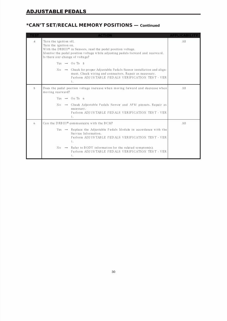
7/21/2019 2005 RS Chassis
http://slidepdf.com/reader/full/2005-rs-chassis 34/86
TEST ACTION APPLICABILITY
4 Tu r n t h e i gn it i on of f.
Turn the ignition on.
W it h t h e DR B I I I in Sensors, read the pedal position voltage.
M on it or t h e p eda l p osit ion v olt a ge w h ile a dju st in g p eda ls for w a r d a n d r ea r w a r d.I s t h er e a n y ch a n ge of v olt a ge?
All
Yes → G o To 5
No → Check for proper Adjustable Peda ls Sensor installa tion and align-
ment. Check wiring and connectors. Repair as necessary.
P erform ADJ US TAB LE P ED ALS VERIFI CATION TES T - VER
1.
5 D o es t h e p ed a l pos i t ion v ol t a g e i n cr e a s e w h e n m ov in g f or w a r d a n d d e cr e a s e w h e n
mov in g r ea r w a r d?
All
Yes → G o To 6
No → C h e ck A d ju s t a b l e P e d a ls S e n s or a n d AP M p in ou t s . R e pa i r a s
necessary.P erform ADJ US TAB LE P ED ALS VERIFI CATION TES T - VER
1.
6 C a n t h e D RB II I com m un ica t e w it h t h e B C M? All
Yes → R epla ce t h e Adju s t a ble P eda ls M odu le in a ccor da n ce w it h t h e
Service Information.
P erform ADJ US TAB LE P ED ALS VERIFI CATION TES T - VER
1.
No → Refer to B ODY informat ion for the relat ed symptom(s).
P erform ADJ US TAB LE P ED ALS VERIFI CATION TES T - VER
1.
30
ADJUSTABLE PEDALS
*CAN’T SET/RECALL MEMORY POSITIONS — Continued

7/21/2019 2005 RS Chassis
http://slidepdf.com/reader/full/2005-rs-chassis 35/86
Symptom:BUS SYSTEM COMMUNICATION FAILURE
When Monitored and Set Condition:
BUS SYSTEM COMMUNICATION FAILURE
When Monitored: Ignit ion ON, continuously.
Set Condition: When the CAB does not receive a messa ge from the inst rument cluster for
10 seconds.
POSSIBLE CAUSES
INTERMITTENT CONDITION
ELECTRO-MECHANICAL INSTRUMENT CLUSTER DTC PRESENT
B U S C I R C U I T O P E N
CAB - INTERNAL FAILURE
TEST ACTION APPLICABILITY
1 Tu rn t h e ig ni ti on on .
W it h t h e DR B I I I, r ea d DTC s .
W it h t h e DR B I I I, r ea d Fr eeze Fr a me in for ma t ion .
W it h t h e DR B I I I, erase DTCs.
Turn the ignition off.
Turn the ignition on.
W it h t h e DR B I I I, r ea d DTC s .
D o es t h e D R B I I I dis pla y B U S SYSTE M C OM M U NI C ATI ON FAI L U R E ?
All
Yes → G o To 2
No → G o To 4
2 Tu rn t h e ig ni ti on on .
W it h t h e DR B I I I, r ea d E M I C DTC s .
D o es t h e D R B I I I dis p la y NO A B S M E SSA G E R E C E I V E D?
All
Yes → R efer t o s ympt om NO AB S M E SS AG E R E C E I V E D in t h e B ODY/
INSTRUMENT CLUSTER category.
P erform AB S VERIFI CATION TES T - VER 1.
No → G o To 3
31
BRAKES (CAB)

7/21/2019 2005 RS Chassis
http://slidepdf.com/reader/full/2005-rs-chassis 36/86
TEST ACTION APPLICABILITY
3 Tu r n t h e i gn it i on of f.
Disconnect the negative (-) battery cable.
Disconnect the CAB harness connector.
NOTE : check connector - Clean/repair as necessary.M ea s u r e t h e r es ist a n ce of t h e B u s cir cu it bet w een t h e C A B con n ect or a n d t h e D a t a
Link C onnector (DLC ).
Is the resistance below 5.0 ohms?
All
Yes → R epla ce t h e C on t r oller A n t ilock B r a k e in a ccor da n ce w it h t h e
Service Information.
P erform AB S VERIFI CATION TES T - VER 1.
No → Repair the B us circuit for an open.
P erform AB S VERIFI CATION TES T - VER 1.
4 Tu r n t h e i gn it i on of f.
Visually in spect t he relat ed w iring ha rness. Look for an y cha fed, pierced, pinched, or
p a r t ia lly br oken w ir es.
Visually inspect the related wire harness connectors. Look for broken, bent, pushedout, or corroded terminals.
Were a ny problems found?
All
Yes → Repair as necessary.
P erform AB S VERIFI CATION TES T - VER 1.
No → Test Complet e.
32
BRAKES (CAB)
BUS SYSTEM COMMUNICATION FAIL URE — Continued

7/21/2019 2005 RS Chassis
http://slidepdf.com/reader/full/2005-rs-chassis 37/86
Symptom:CAB INTERNAL FAILURE
When Monitored and Set Condition:
CAB INTERNAL FAILURE
When Monitored: Ignit ion on. The CAB m onitors its interna l microprocessors for correct
operation.
S e t C o n di t i on : I f t h e C AB d et e ct s a n i n t e r na l f a u l t , t h e D TC i s s e t .
POSSIBLE CAUSES
IN TE RMI TTE NT D TC
DAMAG ED CAB/CAB HARNESS CONNEC TOR
C AB - G R O U N D C I R C U I T OP E N
ABS VALVE FUSED B(+ ) CIRCUIT OPEN
AB S P U M P F U S E D B ( + ) C I R C U I T O P E N
CAB - INTER NAL FAU LT
TEST ACTION APPLICABILITY
1 Tu rn t h e ig ni ti on on .
W it h t h e DR B I I I, r ea d DTC s .
W it h t h e DR B I I I, erase DTCs.
Turn the ignition off.
Turn the ignition on.
W it h t h e DR B I I I, r ea d DTC s .
D o es t h e D R B I I I display CAB INTERNAL FAILURE?
All
Yes → G o To 2
No → G o To 6
2 Tu r n t h e i gn it i on of f.
Disconnect the CAB harness connector.
Inspect the CAB/CAB h ar ness connector for da ma ge.
Is there any broken, bent, pushed out, corroded or spread terminals?
All
Yes → Repair as necessary.
P erform AB S VERIFI CATION TES T - VER 1.
No → G o To 3
3 Tu r n t h e i gn it i on of f.
Disconnect the CAB harness connector.
Using a 12-volt test light connected to 12-volts, probe the CAB harness connector
ground circuits.
Did t h e t es t l igh t i l lu min a t e?
All
Yes → G o To 4
No → Repair the CAB G round circuit for an open.
P erform AB S VERIFI CATION TES T - VER 1.
33
BRAKES (CAB)
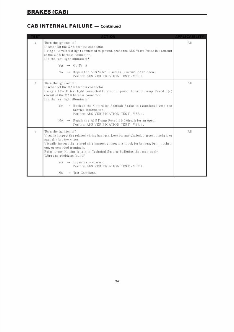
7/21/2019 2005 RS Chassis
http://slidepdf.com/reader/full/2005-rs-chassis 38/86
TEST ACTION APPLICABILITY
4 Tu r n t h e i gn it i on of f.
Disconnect the CAB harness connector.
Us ing a 12-volt test ligh t connected to ground, probe the AB S Va lve Fused B (+ ) circuit
at the CAB harness connector.Did t h e t es t l igh t i l lu min a t e?
All
Yes → G o To 5
No → Repair t he AB S Valve Fused B (+ ) circuit for an open.
P erform AB S VERIFI CATION TES T - VER 1.
5 Tu r n t h e i gn it i on of f.
Disconnect the CAB harness connector.
U s in g a 12-v olt t es t l igh t con n ect ed t o gr ou n d, p r obe t h e A B S P u mp Fu s ed B (+ )
circuit at the CAB harness connector.
Did t h e t es t l igh t i l lu min a t e?
All
Yes → R epla ce t h e C on t r oller A n t ilock B r a k e in a ccor da n ce w it h t h e
Service Information.
P erform AB S VERIFI CATION TES T - VER 1.
No → Repair th e AB S P ump Fused B (+ ) circuit for an open.
P erform AB S VERIFI CATION TES T - VER 1.
6 Tu r n t h e i gn it i on of f.
Visually inspect th e relat ed w iring ha rness. Look for an y cha fed, pierced, pinched, or
p a r t ia lly br oken w ir es.
Visually inspect the related wire harness connectors. Look for broken, bent, pushed
out, or corroded terminals.
Refer to any Hotline letters or Technical S ervice Bu lletins tha t m ay apply.
Were a ny problems found?
All
Yes → Repair as necessary.
P erform AB S VERIFI CATION TES T - VER 1.
No → Test Complet e.
34
BRAKES (CAB)
CAB INTERNAL FAILURE — Continued

7/21/2019 2005 RS Chassis
http://slidepdf.com/reader/full/2005-rs-chassis 39/86
Symptom:CLUSTER LAMP FAILURE
When Monitored and Set Condition:
CLUSTER LAMP FAILURE
When Monitored: Key ON. After K ey-ON bulb check.
S e t C on d i t ion : Wh e n t h e i n s t r u m en t cl u st e r i n f or m s t h e C AB t h a t t h e c lu s t er ca n n o t
t u r n o n t h e AB S L a m p .
POSSIBLE CAUSES
I N S TRU M EN T C L U S TER O R AB S D TC P RES EN T
INSTRUMENT CLUSTER
CAB - NO D TC SIG NAL TO THE INSTRU MENT CLUS TER
C A B - N O K EY-O N B U L B C H EC K S I G N AL
CAB - PE RMANENT FAULT SIG NAL
TEST ACTION APPLICABILITY
1 Tu rn t h e ig ni ti on on .
W it h t h e DR B I I I, r ea d DTC s .
Ar e t h er e a n y I n s t r u men t C lu s t er or AB S DTC s p r es en t ?
All
Yes → Refer to the a ppropriat e cat egory for the relat ed symptom(s).
P erform AB S VERIFI CATION TES T - VER 1.
No → G o To 2
2 Tu r n t h e i gn it i on of f.
Perform the Key-on Bulb Check.
Does t h e A B S Wa r n in g I n dica t or l igh t a n d t h en go ou t a f t er a few s econ ds?
All
Yes → G o To 3
No. Light remains after bulb check.
R epla ce t h e C on t r oller A n t ilock B r a k e in a ccor da n ce w it h t h e
Service Information.
P erform ABS VERIFI CATION TES T - VER 1.
No. Indicator never comes on.
G o To 4
35
BRAKES (CAB)

7/21/2019 2005 RS Chassis
http://slidepdf.com/reader/full/2005-rs-chassis 40/86
TEST ACTION APPLICABILITY
3 NOTE: The DRBIII communication with the CAB must be operational forthe result of this test to be valid.Turn the ignition off.
Remove AB S Valve fuse.Perform the Key-on Bulb Check.
Does t h e AB S I n dica t or r ema in on a f t er t h e bu lb ch eck ?
All
Yes → Test Complete.
No → R epla ce t h e C on t r oller A n t ilock B r a k e in a ccor da n ce w it h t h e
Service Information.
P erform AB S VERIFI CATION TES T - VER 1.
4 NOTE: The following steps will initiate the Instrument Cluster self test.Turn the ignition off.
P r es s a n d h old t h e odomet er r es et bu t t on .
Turn t he ignition to RU N.
Obs er v e t h e I n s t r u men t C lu s t er in dica t or s.
Release the odometer reset button.Did t h e AB S I n dica t or i llu min a t e du r in g t h e I n s t r u men t C lu s t er s elf t es t ?
All
Yes → R epla ce t h e C on t r oller A n t ilock B r a k e in a ccor da n ce w it h t h e
Service Information.
P erform AB S VERIFI CATION TES T - VER 1.
No → R epla ce t h e I n s t r u men t C lu s t er in a ccor da n ce w it h t h e S er v ice
I n for ma t ion .
P erform AB S VERIFI CATION TES T - VER 1.
36
BRAKES (CAB)
CLUSTER LAMP FAILURE — Continued

7/21/2019 2005 RS Chassis
http://slidepdf.com/reader/full/2005-rs-chassis 41/86
Symptom:INCORRECT TONE WHEEL FAILURE
When Monitored and Set Condition:
INCORRECT TONE WHEEL FAILURE
When Monit ored: Ign ition ON. Vehicle speed above 40 km/h (25 mph) for 2 minut es.
Set C ondition: When the CAB detects a n unexpected w heel speed condition ca used by a
tire size that does not meet vehicle specification.
37
BRAKES (CAB)

7/21/2019 2005 RS Chassis
http://slidepdf.com/reader/full/2005-rs-chassis 42/86
Symptom List:LEFT FRONT SENSOR CIRCUIT FAILURELEFT REAR SENSOR CIRCUIT FAILURERIGHT FRONT SENSOR CIRCUIT FAILURERIGHT REAR SENSOR CIRCUIT FAILURE
Test Note: All symptoms listed above are diagnosed using thesame tests.Thetitle for the tests will be LEFT FRONT SENSOR CIRCUI TFAILURE.
When Monitored and Set Condition:
LEFT FRONT SENSOR CIRCUIT FAILURE
When Monitored: Ignit ion on. The CAB m onitors t he w heel speed circuit continuously.
S e t C on d i t ion : I f t h e C AB d et e ct s a n op en or s h or t e d w h e el s p ee d s e n sor ci r cu i t , t h e
Dia gnost ic Trouble Code (DTC) w ill set.
LEFT REAR SENSOR CIRCUIT FAILURE
When Monitored: Ignit ion on. The CAB m onitors t he w heel speed circuit continuously.
S e t C on d i t ion : I f t h e C AB d et e ct s a n op en or s h or t e d w h e el s p ee d s e n sor ci r cu i t , t h e
Dia gnost ic Trouble Code (DTC) w ill set.
RIGHT FRONT SENSOR CIRCUIT FAILURE
When Monitored: Ignit ion on. The CAB m onitors t he w heel speed circuit continuously.
S e t C on d i t ion : I f t h e C AB d et e ct s a n op en or s h or t e d w h e el s p ee d s e n sor ci r cu i t , t h e
Dia gnost ic Trouble Code (DTC) w ill set.
RIGHT REAR SENSOR CIRCUIT FAILURE
When Monitored: Ignit ion on. The CAB m onitors t he w heel speed circuit continuously.
S e t C on d i t ion : I f t h e C AB d et e ct s a n op en or s h or t e d w h e el s p ee d s e n sor ci r cu i t , t h e
Dia gnost ic Trouble Code (DTC) w ill set.
POSSIBLE CAUSESINTERMITTENT CONDITION
W HEEL S PEED S EN S O R O R C O N N EC T O R D A M A G E
WH E E L S P E E D S E N S O R S I G N AL C I R C U I T FAU L T
WHE EL S P EE D S E N S O R 12 VO LT S U P P LY C I RC U I T S HO RT TO G RO U N D
WH E E L S P E E D S E N S O R 1 2 VO LT S U P P L Y C I R C U I T OP E N
WH E E L S P E E D S E N S O R S I G N AL C I R C U I T S H O R T TO G R O U N D
WH E E L S P E E D S E N S O R S I G N AL C I R C U I T O P E N
38
BRAKES (CAB)
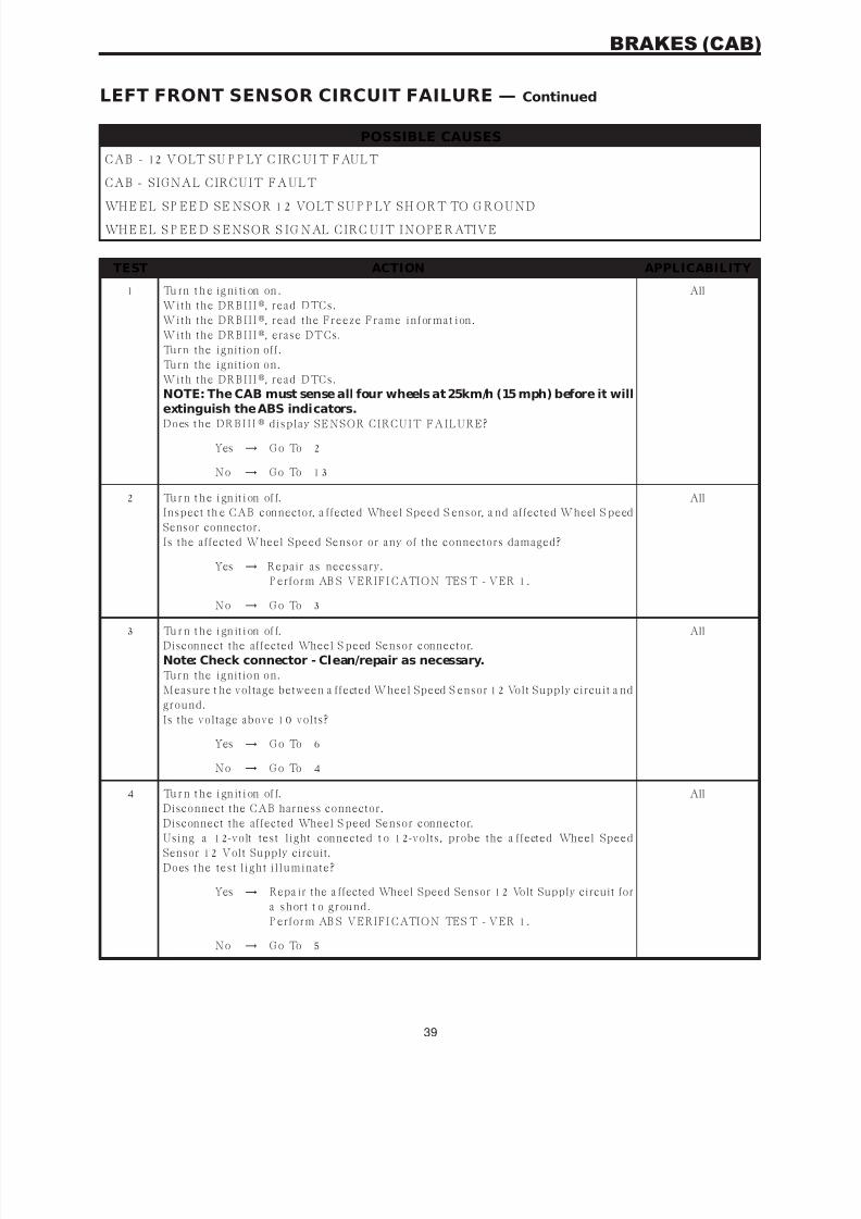
7/21/2019 2005 RS Chassis
http://slidepdf.com/reader/full/2005-rs-chassis 43/86
POSSIBLE CAUSES
CAB - 12 VOLT SU P P LY C IRC UI T FAULT
CAB - SIGNAL CIRCUIT FAULT
WHE EL S P EE D S E N S O R 12 VO LT S U P P LY S H O RT TO G RO U N D
WHE EL S P EE D S EN S O R S I G N AL C I RC U I T I N O PE RATI V E
TEST ACTION APPLICABILITY
1 Tu rn t h e ig ni ti on on .
W it h t h e DR B I I I, r ea d DTC s .
W it h t h e DR B I I I, r ea d t h e Fr eez e Fr a me in for ma t ion .
W it h t h e DR B I I I, erase DTCs.
Turn the ignition off.
Turn the ignition on.
W it h t h e DR B I I I, r ea d DTC s .
NOTE: The CAB must sense all four wheels at 25km/h (15 mph) before it will
extinguish the ABS indicators.D o es t h e D R B I I I dis p la y SE NSOR C I R C U I T FA I L U R E ?
All
Yes → G o To 2
No → G o To 1 3
2 Tu r n t h e i gn it i on of f.
Inspect th e CAB connector, a ffected Wheel Speed S ensor, a nd affected Wheel S peed
Sensor connector.
Is the affected Wheel Speed Sensor or any of the connectors damaged?
All
Yes → Repair as necessary.
P erform AB S VERIFI CATION TES T - VER 1.
No → G o To 3
3 Tu r n t h e i gn it i on of f.
Disconnect the affected Wheel S peed Sensor connector.
Note: Check connector - Clean/repair as necessary.Turn the ignition on.
Measure t he voltage between a ffected Wheel Speed S ensor 12 Volt Supply circuit a nd
ground.
Is the voltage above 10 volts?
All
Yes → G o To 6
No → G o To 4
4 Tu r n t h e i gn it i on of f.
Disconnect the CAB harness connector.
Disconnect the affected Wheel S peed Sensor connector.Using a 12-volt test light connected t o 12-volts, probe the a ffected Wheel Speed
Sensor 12 Volt Supply circuit.
Does t h e t es t l igh t i l lu min a t e?
All
Yes → Repa ir the a ffected Wheel Speed Sensor 12 Volt Supply circuit for
a s h or t t o gr ou n d.
P erform AB S VERIFI CATION TES T - VER 1.
No → G o To 5
39
BRAKES (CAB)
LEFT FRONT SENSOR CIRCUIT FAILURE — Continued

7/21/2019 2005 RS Chassis
http://slidepdf.com/reader/full/2005-rs-chassis 44/86
TEST ACTION APPLICABILITY
5 Tu r n t h e i gn it i on of f.
Disconnect the CAB harness connector.
Disconnect the affected Wheel S peed Sensor connector.
Connect a jumper w ire betw een a ffected Wheel Speed S ensor 12 Volt Supply circuita n d gr ou n d.
Using a 12-volt test light connected t o 12-volts, probe the a ffected Wheel Speed
Sensor 12 Volt Supply circuit.
Does t h e t es t l igh t i l lu min a t e?
All
Yes → G o To 6
No → Repa ir the a ffected Wheel Speed Sens or 12 Volt Supply circuit for
an open.
P erform AB S VERIFI CATION TES T - VER 1.
6 Tu r n t h e i gn it i on of f.
Disconnect the affected Wheel S peed Sensor connector.
NOTE : Check connector - Clean/repair as necessary.
Turn the ignition on.Measure th e volta ge between a ffected Wheel Speed Sensor Signa l circuit an d ground.
I s t h e v olt a ge a bov e 1 v olt ?
All
Yes → Repair the a ffected Wheel Speed Sensor Signa l circuit for a short
to voltage.
P erform AB S VERIFI CATION TES T - VER 1.
No → G o To 7
7 Tu r n t h e i gn it i on of f.
Disconnect the CAB harness connector.
Disconnect the affected Wheel S peed Sensor connector.
Using a 12-volt test light connected t o 12-volts, probe the a ffected Wheel Speed
Sensor Signal circuit .
Does t h e t es t l igh t i l lu min a t e?
All
Yes → Repair the a ffected Wheel Speed Sensor Signa l circuit for a short
t o gr ou n d.
P erform AB S VERIFI CATION TES T - VER 1.
No → G o To 8
8 Tu r n t h e i gn it i on of f.
Disconnect the CAB harness connector.
Disconnect the affected Wheel S peed Sensor connector.
C on n ect a ju mp er w ir e bet w een a f fect ed Wh eel S p eed S en s or Sign a l cir cu it a n d
ground.
Using a 12-volt test light connected t o 12-volts, probe the a ffected Wheel Speed
Sensor Signal circuit .
Does t h e t es t l igh t i l lu min a t e?
All
Yes → G o To 9
No → Repair th e affected Wheel Speed Sensor Signa l circuit for an open.
P erform AB S VERIFI CATION TES T - VER 1.
40
BRAKES (CAB)
LEFT FRONT SENSOR CIRCUIT FAILURE — Continued

7/21/2019 2005 RS Chassis
http://slidepdf.com/reader/full/2005-rs-chassis 45/86
TEST ACTION APPLICABILITY
9 Tu r n t h e i gn it i on of f.
R emov e t h e C AB h a r n es s s t r a in r elief t o a cces s w ir es .
Reconnect t he C AB ha rness connector.
Turn the ignition on.Measure t he voltage between a ffected Wheel Speed S ensor 12 Volt Supply circuit a nd
ground.
I s t h e v olt a ge a bov e 10 v olt s ?
All
Yes → G o To 1 0
No → R epla ce t h e C on t r oller A n t ilock B r a k e in a ccor da n ce w it h t h e
Service Information.
P erform AB S VERIFI CATION TES T - VER 1.
1 0 Tu r n t h e i g ni t i on o ff .
R emov e t h e C AB h a r n es s s t r a in r elief t o a cces s w ir es .
Reconnect t he C AB ha rness connector.
Turn the ignition on.
Measure t he voltage between a ffected Wheel Speed S ensor 12 Volt Supply circuit a ndaffected Wheel Speed Sensor Signal circuit .
Is the voltage above 10 volts?
All
Yes → G o To 11
No → R epla ce t h e C on t r oller A n t ilock B r a k e in a ccor da n ce w it h t h e
Service Information.
P erform AB S VERIFI CATION TES T - VER 1.
11 Tu r n t h e i g ni t i on o ff .
Reconnect ALL affected Wheel Speed Sensor circuit connectors.
Disconnect the affected Wheel S peed Sensor connector.
Turn the ignition on.
Measure t he voltage of th e affected Wheel Speed Sensor 12 Volt Supply circuit in t he
affected Wheel S peed Sensor connector while reconnecting the sensor connector.Did t h e a f fect ed W h eel Sp eed Sen s or 12 V olt Su p p ly cir cu it dr op v olt a ge t o 0 DC
volts?
All
Yes → Replace the affected Wheel Speed Sensor in accorda nce with th e
Service Information.
P erform AB S VERIFI CATION TES T - VER 1.
No → G o To 1 2
1 2 Tu r n t h e i g n it i on of f.
Reconnect ALL affected Wheel Speed Sensor circuit connectors.
Turn the ignition on.
M ea s u r e t h e DC v olt a ge of t h e W h eel Sp eed Sen s or Sign a l cir cu it in t h e a f fect ed
Wheel Speed Sensor connector.
Slow ly r ot a t e t h e w h eel.Does the DC voltage toggle between 1.6 volts to .8 volts?
All
Yes → G o To 1 3
No → Replace the affected Wheel Speed Sensor in accorda nce with t he
Service Information.
P erform AB S VERIFI CATION TES T - VER 1.
41
BRAKES (CAB)
LEFT FRONT SENSOR CIRCUIT FAILURE — Continued
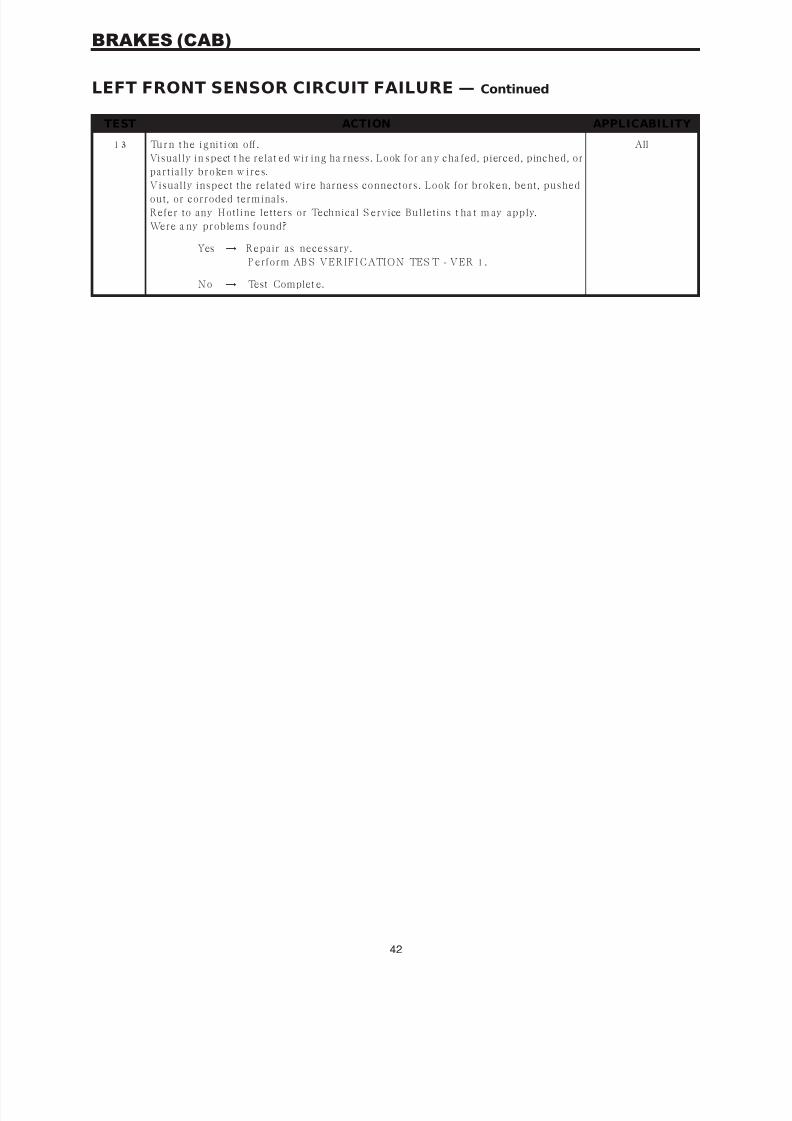
7/21/2019 2005 RS Chassis
http://slidepdf.com/reader/full/2005-rs-chassis 46/86
TEST ACTION APPLICABILITY
1 3 Tu r n t h e i g ni t i on o ff .
Visually in spect t he relat ed wir ing ha rness. Look for an y cha fed, pierced, pinched, or
p a r t ia lly br oken w ir es.
Visually inspect the related wire harness connectors. Look for broken, bent, pushedout, or corroded terminals.
Refer to any Hotline letters or Technical S ervice Bulletins t ha t m ay apply.
Were a ny problems found?
All
Yes → Repair as necessary.
P erform AB S VERIFI CATION TES T - VER 1.
No → Test Complet e.
42
BRAKES (CAB)
LEFT FRONT SENSOR CIRCUIT FAILURE — Continued

7/21/2019 2005 RS Chassis
http://slidepdf.com/reader/full/2005-rs-chassis 47/86
Symptom List:LEFT FRONT WHEEL SPEED SIGNAL FAILURELEFT REAR WHEEL SPEED SIGNAL FAILURERIGHT FRONT WHEEL SPEED SIGNAL FAILURERIGHT REAR WHEEL SPEED SIGNAL FAILURE
Test Note: All symptoms listed above are diagnosed using thesame tests.The title for the tests will be LEFT FRONT WHEEL SPEEDSIGNAL FAILURE.
When Monitored and Set Condition:
LEFT FRONT WHEEL SPEED SIGNAL FAILURE
When Monitored: Wheel speed are checked and verified a t drive off a nd continuously
thereafter.
Set Condit ion: I f , during an AB S stop, the CAB comma nds any valve solenoid on for a n
e xt e n de d l en g t h of t i m e, a n d d oe s n ot s ee a cor r e sp on d in g w h e e l s p ee d ch a n g e , t h e
Diagnostic Trouble Code (DTC) is set . The DTC can also set i f t he signal is m issing or
errat ic .
LEFT REAR WHEEL SPEED SIGNAL FAILURE
When Monitored: Wheel speed are checked and verified a t drive off a nd continuously
thereafter.
Set Condit ion: I f , during an AB S stop, the CAB comma nds any valve solenoid on for a n
e xt e n de d l en g t h of t i m e, a n d d oe s n ot s ee a cor r e sp on d in g w h e e l s p ee d ch a n g e , t h eDiagnostic Trouble Code (DTC) is set . The DTC can also set i f t he signal is m issing or
errat ic .
RIGHT FRONT WHEEL SPEED SIGNAL FAILURE
When Monitored: Wheel speed are checked and verified a t drive off a nd continuously
thereafter.
Set Condit ion: I f , during an AB S stop, the CAB comma nds any valve solenoid on for a n
e xt e n de d l en g t h of t i m e, a n d d oe s n ot s ee a cor r e sp on d in g w h e e l s p ee d ch a n g e , t h e
Diagnostic Trouble Code (DTC) is set . The DTC can also set i f t he signal is m issing or
errat ic .
RIGHT REAR WHEEL SPEED SIGNAL FAILURE
When Monitored: Wheel speed are checked and verified a t drive off a nd continuously
thereafter.
Set Condit ion: I f , during an AB S stop, the CAB comma nds any valve solenoid on for a n
e xt e n de d l en g t h of t i m e, a n d d oe s n ot s ee a cor r e sp on d in g w h e e l s p ee d ch a n g e , t h e
Diagnostic Trouble Code (DTC) is set . The DTC can also set i f t he signal is m issing or
errat ic .
43
BRAKES (CAB)

7/21/2019 2005 RS Chassis
http://slidepdf.com/reader/full/2005-rs-chassis 48/86
POSSIBLE CAUSES
WH E E L S P E E D S I G N AL F AI L U R E D TC P R E S E N T
AF F E C TED WHE EL S P EE D S EN S O R S I G N AL I N O P ERATI V E
AF F E C TED WHE EL S P EE D S EN S O R C O N N EC TO R D AM AG E D
AF F E C TED WHE EL S P EE D S EN S O R TO N E WHE EL D AM AG ED
AF F E C TED WHE EL S P EE D S EN S O R AI R G AP F AU L T
WHE EL B E ARI N G F AU L T
B R AK E L I N I N G F AU L T
AF F E C TED WHE EL S P EE D S EN S O R C I RC U I T EL EC TRI C A L FAU L T
TEST ACTION APPLICABILITY
1 Tu rn t h e ig ni ti on on .
W it h t h e DR B I I I, r ea d DTC s .
W it h t h e DR B I I I, r ea d Fr eeze Fr a me in for ma t ion .
NOTE: The CAB must sense ALL 4 wheels at 25 km/h (15 mph) before it willextinguish the ABS indicators.D oe s t h e D R B I I I di sp la y WH E E L S P E E D S I G N AL F AI L U R E a n d S E N S O R
C I R C U I T FAI L U R E ?
All
Yes → Refer to the a ffected Wheel Speed SE NSOR C IRCU IT FAILU RE
for the related symptom(s).
P erform AB S VERIFI CATION TES T - VER 1.
No → G o To 2
2 Tu rn t h e ig ni ti on on .
Wit h t h e D R B I I I in Sensors, monitor ALL t he Wheel Speed Sensor Signa ls wh ile an
a s s is t a n t dr iv es t h e v eh icle.
Slowly accelera te a s str aigh t a s possible from a stop to 24 km/h (15 mph).
Is t he a ffected Wheel Speed S ignal showing 0 km/h (0 mph)?
All
Yes → G o To 3
No → Th e c on d i t ion i s n o t p r es en t a t t h i s t i m e . M o ni t or D R B I I I
p a r a met er s w h ile w igglin g t h e r ela t ed w ir in g h a r n es s . R efer t o
a n y Tech n ica l Ser v ice B u llet in s (TSB ) t h a t ma y a p p ly. Vis u a lly
in s pect t h e r ela t ed w ir in g h a r n es s a n d con n ect or t er min a ls .
P erform AB S VERIFI CATION TES T - VER 1.
3 Tu r n t h e i gn it i on of f.Inspect th e CAB connector, a ffected Wheel Speed S ensor, a nd affected Wheel Speed
Sensor connector.
Is the Wheel Speed Sensor or any connector damaged?
All
Yes → Repair as necessary.
P erform AB S VERIFI CATION TES T - VER 1.
No → G o To 4
44
BRAKES (CAB)
LEFT FRONT WHEEL SPEED SIGNAL FAILURE — Continued

7/21/2019 2005 RS Chassis
http://slidepdf.com/reader/full/2005-rs-chassis 49/86
TEST ACTION APPLICABILITY
4 Tu r n i gn it i on of f.
Inspect th e a ffected Tone Wheel for da ma ged, missing teeth, cracks, or looseness.
NOTE :The Tone Wheel teeth should beperfectly square,not bent,or nicked.
Is the affected Tone Wheel OK?
All
Yes → G o To 5
No → Replace the Tone Wheel in accorda nce with t he Service Informa-
tion.
P erform AB S VERIFI CATION TES T - VER 1.
5 Tu r n t h e i gn it i on of f.
U s in g a Feeler G a u ge, mea s u r e t h e a f fect ed W h eel Sp eed S en s or A ir G a p .
NOTE : Refer to the appropriate service information, if necessary, forprocedures or specifications.I s t h e A ir G a p OK?
All
Yes → G o To 6
No → Repair as necessary.P erform AB S VERIFI CATION TES T - VER 1.
6 Tu r n t h e i gn it i on of f.
Inspect the wheel bearings for excessive runout or clearance.
NOTE : Refer to the appropriate service information, if necessary, forprocedures or specifications.I s t h e bea r in g clea r a n ce OK ?
All
Yes → G o To 7
No → Repair as necessary.
P erform AB S VERIFI CATION TES T - VER 1.
7 Tu r n t h e i gn it i on of f.
Visually inspect brakes for locking up due to lining contamination or overheating.Inspect all components for defects which may cause a Signal DTC to set.
I s a n y compon en t da ma ged?
All
Yes → Repair as necessary.
P erform AB S VERIFI CATION TES T - VER 1.
No → R ef er t o s y mp tom S E N S O R C I R C U I T FAI L U R E f or f ur t h er
diagnostics.
P erform AB S VERIFI CATION TES T - VER 1.
45
BRAKES (CAB)
LEFT FRONT WHEEL SPEED SIGNAL FAILURE — Continued

7/21/2019 2005 RS Chassis
http://slidepdf.com/reader/full/2005-rs-chassis 50/86
Symptom:PUMP CIRCUIT FAILURE
When Monitored and Set Condition:
PUMP CIRCUIT FAILURE
When Monitored: Ignit ion on. The CAB comma nds t he pump on at 20 km/h (12 mph) to
check its operation, if the brake switch is not applied. If the brake is applied, the test will
ru n a t 40 km/h (25 mph).
Set Condition: The DTC is stored w hen the CAB d etects: 1) Improper volta ge decay a fter
the pump w a s tur ned off. 2) P ump not energized by the CAB, but volta ge is present for 3.5
seconds. 3) Pump is turned on by t he CAB, but without sufficient voltage to operate it .
POSSIBLE CAUSES
CAB - PUMP MOTOR RUNNING CONTINUOUSLY
AB S P U M P F U S E
ABS PUMP MOTOR INTERMITTENT DTC
DAMAG ED CAB/CAB HARNESS CONNEC TOR
AB S P UMP FU SE D B (+ ) CIRCU IT INTERMI TTENT SHORT TO G ROUND
AB S P U M P F U S ED B ( + ) C I RC U I T S HO RT TO G RO U N D
CAB - INTER NAL FAU LT
AB S P UMP MOTOR INOP ERATIVE
A B S PU M P M O T O R O PEN
AB S P U M P M O TO R B (+ ) C I RC U I T O PE N
AB S P U M P M OTO R G R O U N D C I R C U I T OP E N
CAB - INTER NAL FAU LT
TEST ACTION APPLICABILITY
1 Tu r n t h e i gn it i on of f.
Turn the ignition on.
Monitor the ABS Pump Motor for continuous operation.
NOTE: The CAB must sense ALL wheels at 25 km/h (15 mph) before it will
extinguish the ABS indicators.I s t h e AB S P u m p M ot or r u n n in g con t in u ou s ly?
All
Yes → R epla ce t h e C on t r oller A n t ilock B r a k e in a ccor da n ce w it h t h e
Service Information.
P erform AB S VERIFI CATION TES T - VER 1.
No → G o To 2
46
BRAKES (CAB)
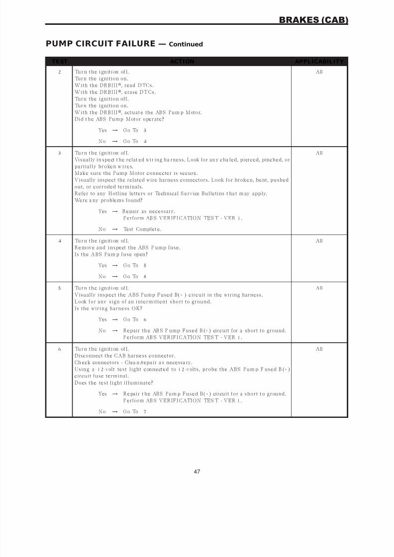
7/21/2019 2005 RS Chassis
http://slidepdf.com/reader/full/2005-rs-chassis 51/86
TEST ACTION APPLICABILITY
2 Tu r n t h e i gn it i on of f.
Turn the ignition on.
W it h t h e DR B I I I, r ea d DTC s .
W it h t h e DR B I I I
, erase DTCs.Turn the ignition off.
Turn the ignition on.
W it h t h e DR B I I I, a ct u a t e t h e AB S P u m p M ot or.
Did t h e AB S P u mp M ot or oper a t e?
All
Yes → G o To 3
No → G o To 4
3 Tu r n t h e i gn it i on of f.
Visually in spect t he relat ed wir ing ha rness. Look for an y cha fed, pierced, pinched, or
p a r t ia lly br oken w ir es.
Make sure the Pump Motor connecter is secure.
Visually inspect the related wire harness connectors. Look for broken, bent, pushed
out, or corroded terminals.Refer to any Hotline letters or Technical S ervice Bulletins t ha t m ay apply.
Were a ny problems found?
All
Yes → Repair as necessary.
P erform AB S VERIFI CATION TES T - VER 1.
No → Test Complet e.
4 Tu r n t h e i gn it i on of f.
R emov e a n d in s pect t h e AB S P u mp fu s e.
I s t h e A B S P u m p fu s e op en ?
All
Yes → G o To 5
No → G o To 8
5 Tu r n t h e i gn it i on of f.
Visually inspect the ABS Pump Fused B(+ ) circuit in the wiring harness.
L ook for a n y s ign of a n in t er mit t en t s h or t t o gr ou n d.
I s t h e w ir in g h a r n es s OK?
All
Yes → G o To 6
No → Repair th e AB S P ump Fused B (+ ) circuit for a short to ground.
P erform AB S VERIFI CATION TES T - VER 1.
6 Tu r n t h e i gn it i on of f.
Disconnect the CAB harness connector.
Ch eck connectors - Clea n/repa ir a s necessa ry.
U s in g a 12-v olt t es t l igh t con n ect ed t o 12-v olt s , p r obe t h e A B S P u m p F u s ed B (+ )
circuit fuse terminal.Does t h e t es t l igh t i l lu min a t e?
All
Yes → R epa ir t h e AB S P u m p Fu s ed B (+ ) cir cu it for a s h or t t o gr ou n d.
P erform AB S VERIFI CATION TES T - VER 1.
No → G o To 7
47
BRAKES (CAB)
PUMP CIRCUIT FAILURE — Continued
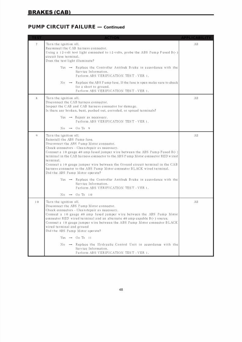
7/21/2019 2005 RS Chassis
http://slidepdf.com/reader/full/2005-rs-chassis 52/86
TEST ACTION APPLICABILITY
7 Tu r n t h e i gn it i on of f.
Reconnect t he C AB ha rness connector.
U s in g a 12-v olt t es t l igh t con n ect ed t o 12-v olt s , p r obe t h e A B S P u m p F u s ed B (+ )
circuit fuse terminal.Does t h e t es t l igh t i l lu min a t e?
All
Yes → R epla ce t h e C on t r oller A n t ilock B r a k e in a ccor da n ce w it h t h e
Service Information.
P erform AB S VERIFI CATION TES T - VER 1.
No → Replace the AB S P ump fuse. If the fuse is open ma ke sure to check
for a short to ground.
P erform AB S VERIFI CATION TES T - VER 1.
8 Tu r n t h e i gn it i on of f.
Disconnect the CAB harness connector.
I n s p ect t h e C AB a n d C AB h a r n es s con n ect or for da ma ge.
Is there any broken, bent, pushed out, corroded, or spread terminals?
All
Yes → Repair as necessary.
P erform AB S VERIFI CATION TES T - VER 1.
No → G o To 9
9 Tu r n t h e i gn it i on of f.
R ein s t a ll t h e AB S P u mp fu s e.
Disconnect t he ABS P ump Motor connector.
Ch eck connectors - Clea n/repa ir a s necessa ry.
C on n ect a 10 ga u ge 40 a mp fu s ed ju mper w ir e bet w een t h e AB S P u m p Fu s ed B (+ )
termina l in the CAB ha rness connector to the AB S P ump Motor connector RED w ired
t er min a l.
C on n ect a 10 ga u ge ju mp er w ir e bet w een t h e G r ou n d cir cu it t er min a l in t h e C A B
h a r n es s con n ect or t o t h e A B S P u mp M ot or con n ect or B L AC K w ir ed t er min a l.
Did t h e AB S P u mp M ot or oper a t e?
All
Yes → R epla ce t h e C on t r oller A n t ilock B r a k e in a ccor da n ce w it h t h e
Service Information.
P erform AB S VERIFI CATION TES T - VER 1.
No → G o To 1 0
1 0 Tu r n t h e i g n it i on of f.
Disconnect t he ABS P ump Motor connector.
Ch eck connectors - Clea n/repa ir a s necessa ry.
C o nn e ct a 1 0 g a u g e 4 0 a m p f u se d j u m pe r w i r e b e t w ee n t h e AB S P u m p M ot or
con n ect or R E D w ir ed t er min a l a n d a n a lt er n a t e 40 a mp ca p a ble B (+ ) s ou r ce.
C on n ect a 10 ga u ge ju mper w ir e bet w een t h e A B S P u mp M ot or con n ect or B L AC K
w ir ed t er min a l a n d gr ou n d
Did t h e AB S P u mp M ot or oper a t e?
All
Yes → G o To 11
No → R ep la c e t h e H y d r a u li c C o n t rol U n i t i n a c cor d a n ce w i t h t h e
Service Information.
P erform AB S VERIFI CATION TES T - VER 1.
48
BRAKES (CAB)
PUMP CIRCUIT FAILURE — Continued

7/21/2019 2005 RS Chassis
http://slidepdf.com/reader/full/2005-rs-chassis 53/86
TEST ACTION APPLICABILITY
11 Tu r n t h e i g ni t i on of f .
Disconnect t he ABS P ump Motor connector.
Ch eck connectors - Clea n/repa ir a s necessa ry.
C on n ect a 10 ga u ge 40 a mp fu s ed ju mper w ir e bet w een t h e AB S P u m p Fu s ed B (+ )termina l in the CAB ha rness connector to the AB S P ump Motor connector RED w ired
t er min a l.
C on n ect a 10 ga u ge ju mper w ir e bet w een t h e A B S P u mp M ot or con n ect or B L AC K
w ir ed t er min a l a n d gr ou n d.
Did t h e AB S P u mp M ot or oper a t e?
All
Yes → Repair th e ABS P ump Motor Fused B(+ ) circuit for an open.
P erform AB S VERIFI CATION TES T - VER 1.
No → Repair the AB S P ump Motor Ground circuit for an open.
P erform AB S VERIFI CATION TES T - VER 1.
49
BRAKES (CAB)
PUMP CIRCUIT FAILURE — Continued

7/21/2019 2005 RS Chassis
http://slidepdf.com/reader/full/2005-rs-chassis 54/86
Symptom:SYSTEM OVER VOLTAGE
When Monitored and Set Condition:
SYSTEM OVER VOLTAGE
When Monitored: Ignit ion on. The CAB monitors th e Fused B (+ ) circuit at all t imes for
proper system voltage.
Set Condit ion: I f t he volta ge is a bove 16.5 volts for great er tha n 420 milliseconds (ms),
the Dia gnostic Trouble Code (DTC) is set.
POSSIBLE CAUSES
IN TE RMI TTE NT D TC
B ATTERY CH ARG ER CONNEC TED
F U S ED I G N I TI O N S WI TC H O U TP U T (RU N ) C I RC U I T HI G H
DAMAG ED CAB/CAB HARNESS CONNEC TOR
C AB - G R O U N D C I R C U I T OP E N
CAB - INTER NAL FAU LT
TEST ACTION APPLICABILITY
1 Tu rn t h e ig ni ti on on .
W it h t h e DR B I I I, read DTC’s.
W it h t h e DR B I I I
, era se D TC’s.Turn the ignition off.
Turn the ignition on.
S t a r t t h e e n g in e .
W it h t h e DR B I I I, read DTC’s.
D o es t h e D R B I I I display SYS TEM OVER VOLTAGE ?
All
Yes → G o To 2
No → G o To 7
2 I s a ba t t er y ch a r ger con n ect ed t o t h e veh icle? All
Yes → E n s u r e t h e ba t t er y is fu lly ch a r ged.
P erform AB S VERIFI CATION TES T - VER 1.
No → G o To 3
50
BRAKES (CAB)
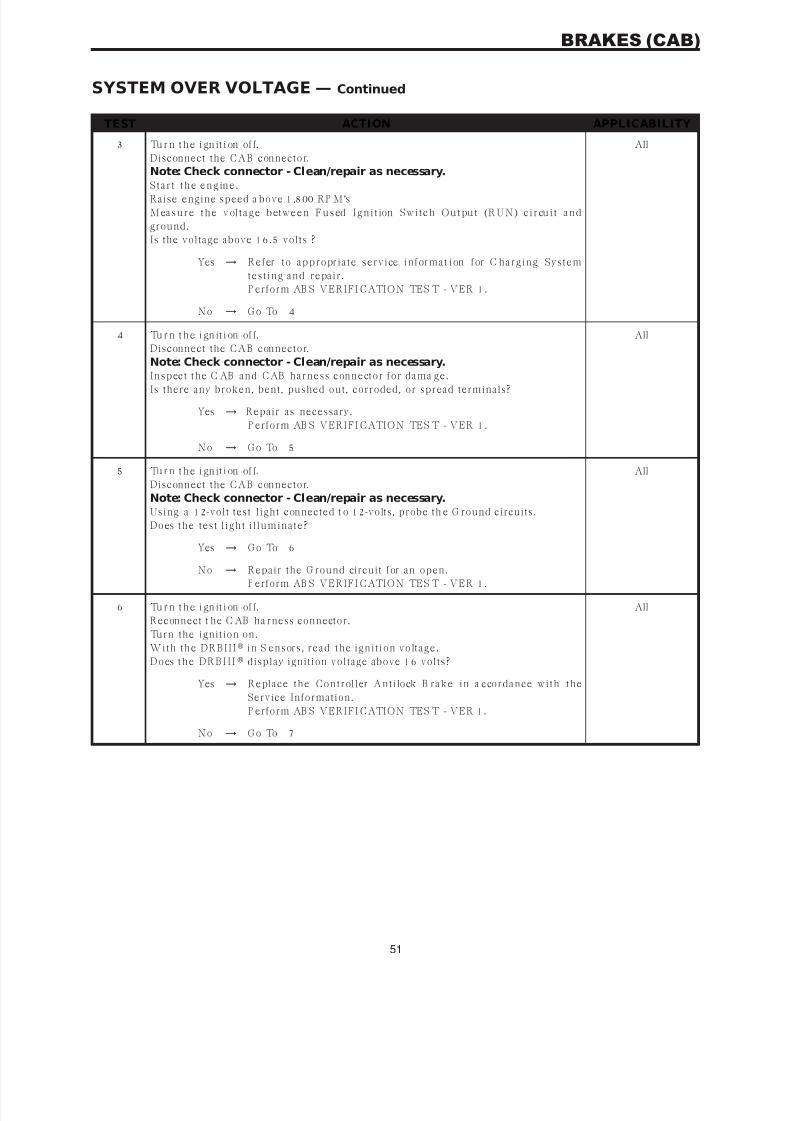
7/21/2019 2005 RS Chassis
http://slidepdf.com/reader/full/2005-rs-chassis 55/86
TEST ACTION APPLICABILITY
3 Tu r n t h e i gn it i on of f.
Disconnect the CAB connector.
Note: Check connector - Clean/repair as necessary.
S t a r t t h e e n g in e .Raise engine speed a bove 1,800 RP M’s
M ea s u r e t h e v ol t a g e b et w e e n F u s ed I g n i t ion S w i t c h O u t pu t (R U N ) c i r cu i t a n d
ground.
Is the voltage above 16.5 volts ?
All
Yes → R efer t o a p p r opr ia t e s er v ice in for ma t ion for C h a r gin g Sys t em
t es t in g a n d r epa ir .
P erform AB S VERIFI CATION TES T - VER 1.
No → G o To 4
4 Tu r n t h e i gn it i on of f.
Disconnect the CAB connector.
Note: Check connector - Clean/repair as necessary.
I n s p ect t h e C AB a n d C AB h a r n es s con n ect or for da ma ge.Is there any broken, bent, pushed out, corroded, or spread terminals?
All
Yes → Repair as necessary.
P erform AB S VERIFI CATION TES T - VER 1.
No → G o To 5
5 Tu r n t h e i gn it i on of f.
Disconnect the CAB connector.
Note: Check connector - Clean/repair as necessary.Using a 12-volt test light connected t o 12-volts, probe th e G round circuits.
Does t h e t es t l igh t i l lu min a t e?
All
Yes → G o To 6
No → Repair the G round circuit for an open.P erform AB S VERIFI CATION TES T - VER 1.
6 Tu r n t h e i gn it i on of f.
Reconnect t he C AB ha rness connector.
Turn the ignition on.
W it h t h e DR B I I I in S en s or s , r ea d t h e ign it ion v olt a ge.
D o es t h e D R B I I I display ignition voltage above 16 volts?
All
Yes → R epla ce t h e C on t r oller A n t ilock B r a k e in a ccor da n ce w it h t h e
Service Information.
P erform AB S VERIFI CATION TES T - VER 1.
No → G o To 7
51
BRAKES (CAB)
SYSTEM OVER VOLTAGE — Continued

7/21/2019 2005 RS Chassis
http://slidepdf.com/reader/full/2005-rs-chassis 56/86
TEST ACTION APPLICABILITY
7 Tu r n t h e i gn it i on of f.
Visually in spect t he relat ed wir ing ha rness. Look for an y cha fed, pierced, pinched, or
p a r t ia lly br oken w ir es.
Visually inspect the related wire harness connectors. Look for broken, bent, pushedout, or corroded terminals.
Refer to any Hotline letters or Technical S ervice Bulletins t ha t m ay apply.
E n s u r e t h e ba t t er y is fu lly ch a r ged.
I n s pe ct t h e v eh i cl e f o r a f t e r m a r k et a c ce ss or i es t h a t m a y e xce ed t h e G e n e r a t or
Sys t em ou t p u t .
U s in g t h e w ir in g dia gr a m/s ch ema t ic a s a gu ide, in s p ect t h e w ir in g a n d con n ect or s .
Were a ny problems found?
All
Yes → Repair as necessary.
P erform AB S VERIFI CATION TES T - VER 1.
No → Test Complet e.
52
BRAKES (CAB)
SYSTEM OVER VOLTAGE — Continued

7/21/2019 2005 RS Chassis
http://slidepdf.com/reader/full/2005-rs-chassis 57/86
Symptom:SYSTEM UNDER VOLTAGE
When Monitored and Set Condition:
SYSTEM UNDER VOLTAGE
Wh e n M o n it o r ed : I g n i t ion on . Th e C AB m on i t or s t h e F u s ed I g n i t ion S w i t ch O u t pu t
circuit volta ge a bove 10 km/h (6 mph) for pr oper s yst em volta ge.
Set C ondition: If th e volta ge is below 9.5 volts, th e Diag nostic Trouble Code (DTC) is set.
POSSIBLE CAUSES
IN TE RMI TTE NT D TC
DAMAG ED CAB/CAB HARNESS CONNEC TOR
RU NNIN G B ATTERY VOLTAG E LOW
C AB - G R O U N D C I R C U I T OP E N
F U S ED I G N I TI O N S WI TC H O U TP U T (RU N ) C I RC U I T O PEN
CAB - INTER NAL FAU LT
TEST ACTION APPLICABILITY
1 Tu rn t h e ig ni ti on on .
W it h t h e DR B I I I, read DTC’s.
W it h t h e DR B I I I, era se D TC’s.
Turn the ignition off.
Turn the ignition on.
S t a r t t h e e n g in e .
Drive the vehicle a bove 16 km/h (10 mph) for a t least 20 seconds.
Stop the vehicle
W it h t h e DR B I I I, read DTC’s.
D o es t h e D R B I I I display SYS TEM U NDE R VOLTAGE ?
All
Yes → G o To 2
No → G o To 6
2 E ngin e R un nin g.
M ea s u r e t h e ba t t er y v olt a ge.
I s t h e ba t t er y v olt a ge below 10 v olt s ?
All
Yes → R efer t o a p pr opr ia t e s er v ice in for ma t ion for ch a r gin g s ys t emt es t in g a n d r epa ir .
P erform AB S VERIFI CATION TES T - VER 1.
No → G o To 3
53
BRAKES (CAB)
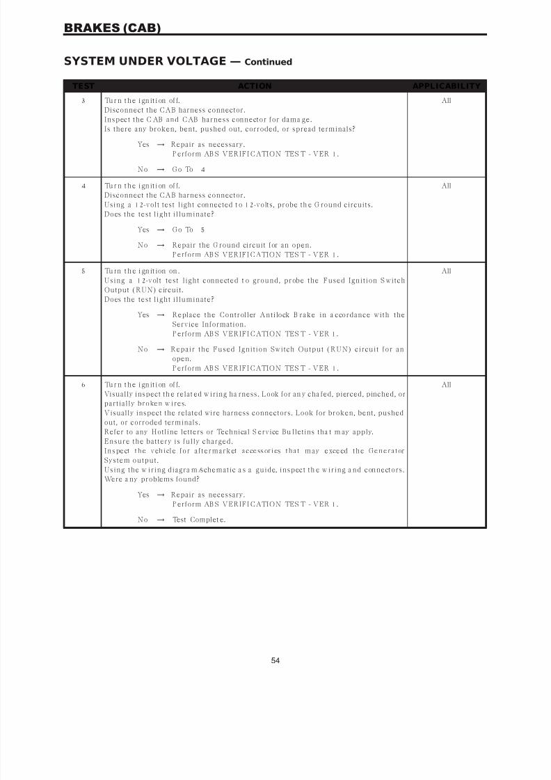
7/21/2019 2005 RS Chassis
http://slidepdf.com/reader/full/2005-rs-chassis 58/86
TEST ACTION APPLICABILITY
3 Tu r n t h e i gn it i on of f.
Disconnect the CAB harness connector.
I n s p ect t h e C AB a n d C AB h a r n es s con n ect or for da ma ge.
Is there any broken, bent, pushed out, corroded, or spread terminals?
All
Yes → Repair as necessary.
P erform AB S VERIFI CATION TES T - VER 1.
No → G o To 4
4 Tu r n t h e i gn it i on of f.
Disconnect the CAB harness connector.
Using a 12-volt test light connected t o 12-volts, probe th e G round circuits.
Does t h e t es t l igh t i l lu min a t e?
All
Yes → G o To 5
No → Repair the G round circuit for an open.
P erform AB S VERIFI CATION TES T - VER 1.
5 Tu rn t h e i gn it ion on .
U s in g a 12-v olt t es t l igh t con n ect ed t o gr ou n d, p r obe t h e Fu s ed I gn it ion S w it ch
Output (RUN) circuit .
Does t h e t es t l igh t i l lu min a t e?
All
Yes → R epla ce t h e C on t r oller A n t ilock B r a k e in a ccor da n ce w it h t h e
Service Information.
P erform AB S VERIFI CATION TES T - VER 1.
No → R ep a ir t h e Fu s ed I gn it ion Sw it ch Ou t p u t (R U N) cir cu it for a n
open.
P erform AB S VERIFI CATION TES T - VER 1.
6 Tu r n t h e i gn it i on of f.
Visually inspect th e relat ed w iring ha rness. Look for an y cha fed, pierced, pinched, orp a r t ia lly br oken w ir es.
Visually inspect the related wire harness connectors. Look for broken, bent, pushed
out, or corroded terminals.
Refer to any Hotline letters or Technical S ervice Bu lletins tha t m ay apply.
E n s u r e t h e ba t t er y is fu lly ch a r ged.
I n s pe ct t h e v eh i cl e f o r a f t e r m a r k et a c ce ss or i es t h a t m a y e xce ed t h e G e n e r a t or
Sys t em ou t p u t .
U s in g t h e w ir in g dia gr a m/s ch ema t ic a s a gu ide, in s p ect t h e w ir in g a n d con n ect or s .
Were a ny problems found?
All
Yes → Repair as necessary.
P erform AB S VERIFI CATION TES T - VER 1.
No → Test Complet e.
54
BRAKES (CAB)
SYSTEM UNDER VOLTAGE — Continued

7/21/2019 2005 RS Chassis
http://slidepdf.com/reader/full/2005-rs-chassis 59/86
Symptom:VALVE POWER FEED FAILURE
When Monitored and Set Condition:
VALVE POWER FEED FAILURE
When Monitored: Ignit ion ON. AB S P ower Relay closed. Va lve comma nd for a pa rt icular
solenoid not present.
Set C ondit ion: Low feedback voltage from the low side of a ll the solenoids.
POSSIBLE CAUSES
IN TE RMI TTE NT D TC
ABS VALVE FUSE
AB S VALVE F U S ED B ( + ) S U P P LY C I RC U I T OP EN
ABS VALVE FUSED B(+ ) CIRCUIT OPEN
AB S VALVE FU SE D B (+ ) CIRCU IT INTERMI TTENT SH ORT TO G ROUND
AB S VALVE FU SE D B (+ ) CIRC UI T SH ORT TO G ROUND
DAMAG ED CAB/CAB HARNESS CONNEC TOR
C AB - G R O U N D C I R C U I T OP E N
CAB - INTER NAL FAU LT
TEST ACTION APPLICABILITY 1 Tu rn t h e ig ni ti on on .
W it h t h e DR B I I I, read DTC’s.
W it h t h e DR B I I I, era se D TC’s.
Turn the ignition off.
Turn the ignition on.
W it h t h e DR B I I I, read DTC’s.
D o es t h e D R B I I I display VALVE POWER FEED FAILURE?
All
Yes → G o To 2
No → G o To 1 0
2 Tu r n t h e i gn it i on of f.
Remove and Inspect the ABS Valve fuse.
Is the ABS Valve fuse open?
All
Yes → G o To 3
No → G o To 6
55
BRAKES (CAB)

7/21/2019 2005 RS Chassis
http://slidepdf.com/reader/full/2005-rs-chassis 60/86
TEST ACTION APPLICABILITY
3 Tu r n t h e i gn it i on of f.
Visually in spect t he AB S Valve Fused B (+ ) circuit in t he w iring ha rness. Look for an y
s ign of a n in t er mit t en t s h or t t o gr ou n d.
I s t h e w ir in g h a r n es s OK?
All
Yes → G o To 4
No → Repair t he AB S Valve Fused B (+ ) circuit for a short to ground.
P erform AB S VERIFI CATION TES T - VER 1.
4 Tu r n t h e i gn it i on of f.
Disconnect the CAB harness connector.
Note: Check connector - Clean/repair as necessary.Using a test light connected to 12 volts, probe th e AB S Valve F used B (+ ) circuit fuse
t er min a l.
Did t h e t es t l igh t i l lu min a t e?
All
Yes → Repair t he ABS Valve Fused B (+ ) circuit for a short t o ground.
P erform AB S VERIFI CATION TES T - VER 1.
No → G o To 5
5 Tu r n t h e i gn it i on of f.
Reconnect t he C AB ha rness connector.
NOTE: The CAB harness connector must be reconnected for the results of this test to be valid.Using a test light connected to 12 volts, probe th e AB S Valve F used B (+ ) circuit fuse
t er min a l.
Did t h e t es t l igh t i l lu min a t e?
All
Yes → R epla ce t h e C on t r oller A n t ilock B r a k e in a ccor da n ce w it h t h e
Service Information.
P erform AB S VERIFI CATION TES T - VER 1.
No → Replace the AB S Valve Fused B (+ ) fuse. If the fuse is open ma kesure to check for a short to ground.
P erform AB S VERIFI CATION TES T - VER 1.
6 Tu r n t h e i gn it i on of f.
Disconnect the CAB harness connector.
I n s p ect t h e C AB a n d C AB h a r n es s con n ect or for da ma ge.
Is there any broken, bent, pushed out, corroded or spread terminals?
All
Yes → Repair as necessary.
P erform AB S VERIFI CATION TES T - VER 1.
No → G o To 7
7 Tu r n t h e i gn it i on of f.
Using a 12-volt test light connected to ground, probe the B(+ ) supply at the ABS Valvefu s e t er min a l.
Did t h e t es t l igh t i l lumin a t e?
All
Yes → G o To 8
No → Repair t he AB S Valve Fused B (+ ) supply circuit for a n open.
P erform AB S VERIFI CATION TES T - VER 1.
56
BRAKES (CAB)
VALVE POWER FEED FAILURE — Continued

7/21/2019 2005 RS Chassis
http://slidepdf.com/reader/full/2005-rs-chassis 61/86
TEST ACTION APPLICABILITY
8 R ei n st a l l t h e AB S Va l ve f us e.
Disconnect the CAB harness connector.
Us ing a 12-volt test ligh t connected to ground, probe the AB S Va lve Fused B (+ ) circuit
at the CAB harness connector.Did t h e t es t l igh t i l lu min a t e?
All
Yes → G o To 9
No → Repair t he AB S Valve Fused B (+ ) circuit for an open.
P erform AB S VERIFI CATION TES T - VER 1.
9 Tu r n t h e i gn it i on of f.
Using a 12-volt test light connected to 12-volts, probe the ground circuits at the CAB
ha rness connector.
Did t h e t es t l igh t i l lu min a t e?
All
Yes → R epla ce t h e C on t r oller A n t ilock B r a k e in a ccor da n ce w it h t h e
Service Information.
P erform AB S VERIFI CATION TES T - VER 1.
No → Repair the CAB G round circuit for an open.
P erform AB S VERIFI CATION TES T - VER 1.
1 0 Tu r n t h e i g n it i on of f.
Visually inspect th e relat ed w iring ha rness. Look for an y cha fed, pierced, pinched, or
p a r t ia lly br oken w ir es.
Visually inspect the related wire harness connectors. Look for broken, bent, pushed
out, or corroded terminals.
Refer to any Hotline letters or Technical S ervice Bu lletins tha t m ay apply.
Were a ny problems found?
All
Yes → Repair as necessary.
P erform AB S VERIFI CATION TES T - VER 1.
No → Test Complet e.
57
BRAKES (CAB)
VALVE POWER FEED FAILURE — Continued
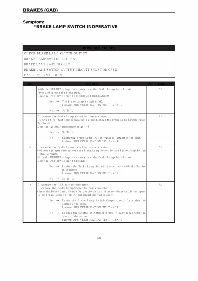
7/21/2019 2005 RS Chassis
http://slidepdf.com/reader/full/2005-rs-chassis 62/86
Symptom:*BRAKE LAMP SWITCH INOPERATIVE
POSSIBLE CAUSES
C H EC K B RA K E L A MP S WI TC H O U TP U T
B RA K E L A M P S W I T C H B + O PEN
BRAKE LAMP SWITCH OPEN
B R AK E L AM P S WI TC H O U TP U T C I RC U I T S HO RT O R O P EN
CAB -- INTERNAL OPEN
TEST ACTION APPLICABILITY
1 Wit h t he D RB I II in I n p u t s /Ou t p u t s , r ea d t h e B r a k e L a mp Sw it ch s t a t e.
P r es s a n d r elea s e t h e br a k e p eda l.
D o es t h e D R B I I I d is pl a y P R E S S E D a n d R E L E A S E D ?
All
Yes → Th e B r a k e L a mp Sw it ch is OK.
P erform AB S VERIFI CATION TES T - VER 1.
No → G o To 2
2 D i s con n e ct t h e B r a k e L a m p S w i t c h h a r n e s s con n e ct o r.
Using a 12-volt test light connected to ground, check the Brake Lamp Switch Fused
B + cir cu it .
Does t h e t es t l igh t i l lu min a t e br igh t ly ?
All
Yes → G o To 3
No → R epa ir t h e B r a k e L a mp Sw it ch Fu s ed B + cir cu it for a n open .
P erform AB S VERIFI CATION TES T - VER 1.
3 D i s con n e ct t h e B r a k e L a m p S w i t c h h a r n e s s con n e ct o r.
C on n ect a ju mper w ir e bet w een t h e B r a k e L a mp Sw it ch B + a n d B r a k e L a mp Sw it ch
Output circuits.
W it h t h e DR B I I I in I n p u t s /Ou t p u t s , r ea d t h e B r a k e L a mp Sw it ch s t a t e.
D o es t h e D R B I I I d is pl a y P R E S S E D ?
All
Yes → R epla ce t h e B r a k e L a mp Sw it ch in a ccor da n ce w it h t h e Ser v ice
I n for ma t ion .
P erform AB S VERIFI CATION TES T - VER 1.
No → G o To 4
4 D i s con n e ct t h e C AB h a r n e s s c on n e ct o r.
Dis con n ect t h e B r a k e L a mp S w it ch h a r n es s con n ect or .
C h eck t h e B r a k e L a mp Sw it ch Ou t p u t cir cu it for a s h or t t o v olt a ge a n d for a n open .
I s t h e B r a k e L a mp S w it ch Ou t p u t cir cu it s h or t ed or open ?
All
Yes → R e pa i r t h e B r a k e L a m p S w i t ch O u t p u t c ir cu i t f or a s h or t t o
voltage or an open.
P erform AB S VERIFI CATION TES T - VER 1.
No → R epla ce t h e C on t r oller A n t ilock B r a k e in a ccor da n ce w it h t h e
Service Information.
P erform AB S VERIFI CATION TES T - VER 1.
58
BRAKES (CAB)

7/21/2019 2005 RS Chassis
http://slidepdf.com/reader/full/2005-rs-chassis 63/86
Symptom:*TRAC OFF INDICATOR NEVER/ALWAYS ON
POSSIBLE CAUSES
TRAC O F F S W G RO U N D O PE N
TRAC OFF SWITCH OPE N
TRAC O F F S WI TC H S E N S E C I RC U I T S HO RT TO B + O R O PE N
B CM -- NO TRAC OFF MES SAGE
CL U S TE R I NTE RNAL FAULT-- TRAC OF F I ND IC ATOR I NOP E RATIVE
CLUSTER-PERMANENT TRAC OFF INDICATOR
TRAC OFF SWITCH INTERNAL SHORT
TRAC OFF SWITCH SENSE CIRCUIT SHORT TO GROUND
B CM -- P ERMANENT TRAC OFF MES SAGE
TEST ACTION APPLICABILITY
1 Note: If any DTC’s are present, they must be repaired prior to performingthis test.Turn the ignition off.
Turn the ignition on.
Observe the TRAC OFF indicator.
Did the TRAC OFF indicator come on for several seconds then go out?
All
Yes → G o To 2
No. TRAC OFF Indicat or does not come on.
G o To 5
No. TRAC OFF Indicator does not go out.
G o To 6
2 D i s con n e ct t h e TR AC OF F S w i t ch h a r n es s con n e ct or .
Using a 12-volt test light connected to 12-volts, check the TRAC OFF Switch Ground
circuit.
Does t h e t es t l igh t i l lu min a t e?
All
Yes → G o To 3
No → Repair the TRAC OFF Sw itch Ground circuit for an open.
P erform AB S VERIFI CATION TES T - VER 1.
3 Tu r n t h e i gn it i on of f.
Disconnect the TRAC OFF Switch harness connector.
Turn the ignition on.
C on n e ct a n d d i sc on n e ct a ju m p er w i r e b e t w e en TR AC O F F S w i t c h G r ou n d a n d
TRAC OFF Switch Sense circuits.
Does t h e TR AC OFF I n dica t or l igh t a n d t h en go ou t ?
All
Yes → Replace the TRAC OFF sw itch.
P erform AB S VERIFI CATION TES T - VER 1.
No → G o To 4
59
BRAKES (CAB)

7/21/2019 2005 RS Chassis
http://slidepdf.com/reader/full/2005-rs-chassis 64/86
TEST ACTION APPLICABILITY
4 Tu r n t h e i gn it i on of f.
Disconnect the TRAC OFF Switch harness connector.
Disconnect the CAB harness connector.
Turn the ignition on.C h eck t h e TR AC OFF Sw it ch Sen s e cir cu it for s h or t t o B + a n d for a n op en .
Is the Sense circuit shorted or open?
All
Yes → Repair the TRAC OFF Sw itch Sense circuit for a short to bat tery
or for an open.
P erform AB S VERIFI CATION TES T - VER 1.
No → Replace the B ody Control Module in accorda nce wit h the Service
I n for ma t ion .
P erform AB S VERIFI CATION TES T - VER 1.
5 Tu r n t h e i gn it i on of f.
NOTE : The purpose of this test is to perform the I nstrument Cluster self test.
Dep r es s a n d h old t h e Odomet er R es et B u t t on .Tu r n t h e Key fr om OFF t o ON a n d t h en ba ck t o OFF.
R elea s e t h e Odomet er R es et B u t t on .
Do t h e I n s t r u men t C lu s t er I n dica t or s a n d G a u ges a ct iv a t e a n d dea ct iv a t e?
All
Yes → Replace the B ody Control Module in accorda nce wit h the Service
I n for ma t ion .
P erform AB S VERIFI CATION TES T - VER 1.
No → R epla ce t h e I n s t r u men t C lu s t er in a ccor da n ce w it h t h e S er v ice
I n for ma t ion .
P erform AB S VERIFI CATION TES T - VER 1.
6 NOTE : The purpose of this test is to perform the Instrument Cluster self test.
Dep r es s a n d h old t h e Odomet er R es et B u t t on .Tu r n t h e Key fr om OFF t o ON a n d t h en ba ck t o OFF.
R elea s e t h e Odomet er R es et B u t t on .
Do t h e I n s t r u men t C lu s t er I n dica t or s a n d G a u ges a ct iv a t e a n d dea ct iv a t e?
All
Yes → G o To 7
No → R epla ce t h e I n s t r u men t C lu s t er in a ccor da n ce w it h t h e S er v ice
I n for ma t ion .
P erform AB S VERIFI CATION TES T - VER 1.
7 Tu r n t h e i gn it i on of f.
Disconnect the TRAC OFF Switch harness connector.
Turn the ignition on.
Does t h e TR AC OFF I n dica t or l igh t a n d t h en go ou t ?
All
Yes → Replace the TRAC OFF sw itch.
P erform AB S VERIFI CATION TES T - VER 1.
No → G o To 8
60
BRAKES (CAB)
*TRAC OFF INDICATOR NEVER/ALWAYS ON — Continued
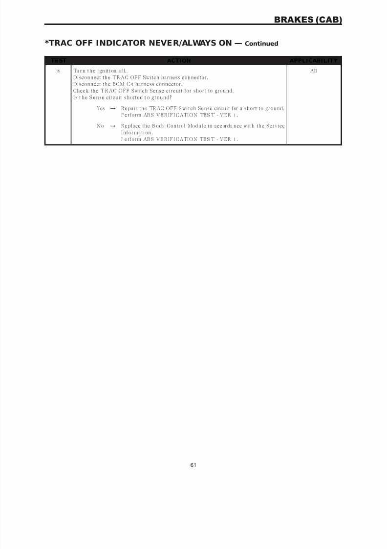
7/21/2019 2005 RS Chassis
http://slidepdf.com/reader/full/2005-rs-chassis 65/86
TEST ACTION APPLICABILITY
8 Tu r n t h e i gn it i on of f.
Disconnect the TRAC OFF Switch harness connector.
Disconnect the BCM C4 harness connector.
Check the TRAC OFF Switch Sense circuit for short to ground.I s t h e S en s e cir cu it s h or t ed t o gr ou n d?
All
Yes → Repair the TRAC OFF S wit ch Sense circuit for a short to ground.
P erform AB S VERIFI CATION TES T - VER 1.
No → Replace the B ody Control Module in accorda nce wit h the Service
I n for ma t ion .
P erform AB S VERIFI CATION TES T - VER 1.
61
BRAKES (CAB)
*TRAC OFF INDICATOR NEVER/ALWAYS ON — Continued
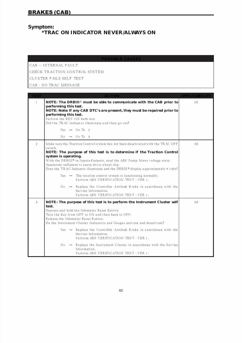
7/21/2019 2005 RS Chassis
http://slidepdf.com/reader/full/2005-rs-chassis 66/86
Symptom:*TRAC ON INDICATOR NEVER/ALWAYS ON
POSSIBLE CAUSES
CAB -- INTERNAL FAULT
CHECK TRACTION CONTROL SYSTEM
C L U S TER F AI L S S EL F TES T
CAB - NO TRAC MES SAGE
TEST ACTION APPLICABILITY
1 NOTE: The DRBIII must be able to communicate with the CAB prior toperforming this test.NOTE: Note: If any CAB DTC’s are present, they must be repaired prior to
performing this test.Perform the KEY-ON bulb test .
Did t h e TR AC I n dica t or i l lu min a t e a n d t h en go ou t ?
All
Yes → G o To 2
No → G o To 3
2 M a k e s u r e t h e Tr a ct ion C on t r ol s ys t em h a s n ot been dea ct iva t ed w it h t h e TR AC OFF
s w it ch .
NOTE: The purpose of this test is to determine if the Traction Controlsystem is operating.W it h t h e DR B I I I in I n p u t s /Ou t p u t s , r ea d t h e AB S P u mp M ot or v olt a ge s t a t e.
Accelerate sufficient t o cause dr ive wh eel slip.
Does the TRAC Indicator illuminate and the DRBIII display a pproximat ely 9 volts?
All
Yes → The tra ction control system is functioning normally.
P erform AB S VERIFI CATION TES T - VER 1.
No → R epla ce t h e C on t r oller A n t ilock B r a k e in a ccor da n ce w it h t h e
Service Information.
P erform AB S VERIFI CATION TES T - VER 1.
3 NOTE : The purpose of this test is to perform the Instrument Cluster self test.Dep r es s a n d h old t h e Odomet er R es et B u t t on .
Tu r n t h e Key fr om OFF t o ON a n d t h en ba ck t o OFF.
R elea s e t h e Odomet er R es et B u t t on .
Do t h e I n s t r u men t C lu s t er I n dica t or s a n d G a u ges a ct iv a t e a n d dea ct iv a t e?
All
Yes → R epla ce t h e C on t r oller A n t ilock B r a k e in a ccor da n ce w it h t h e
Service Information.
P erform AB S VERIFI CATION TES T - VER 1.
No → R epla ce t h e I n s t r u men t C lu s t er in a ccor da n ce w it h t h e S er v ice
I n for ma t ion .
P erform AB S VERIFI CATION TES T - VER 1.
62
BRAKES (CAB)
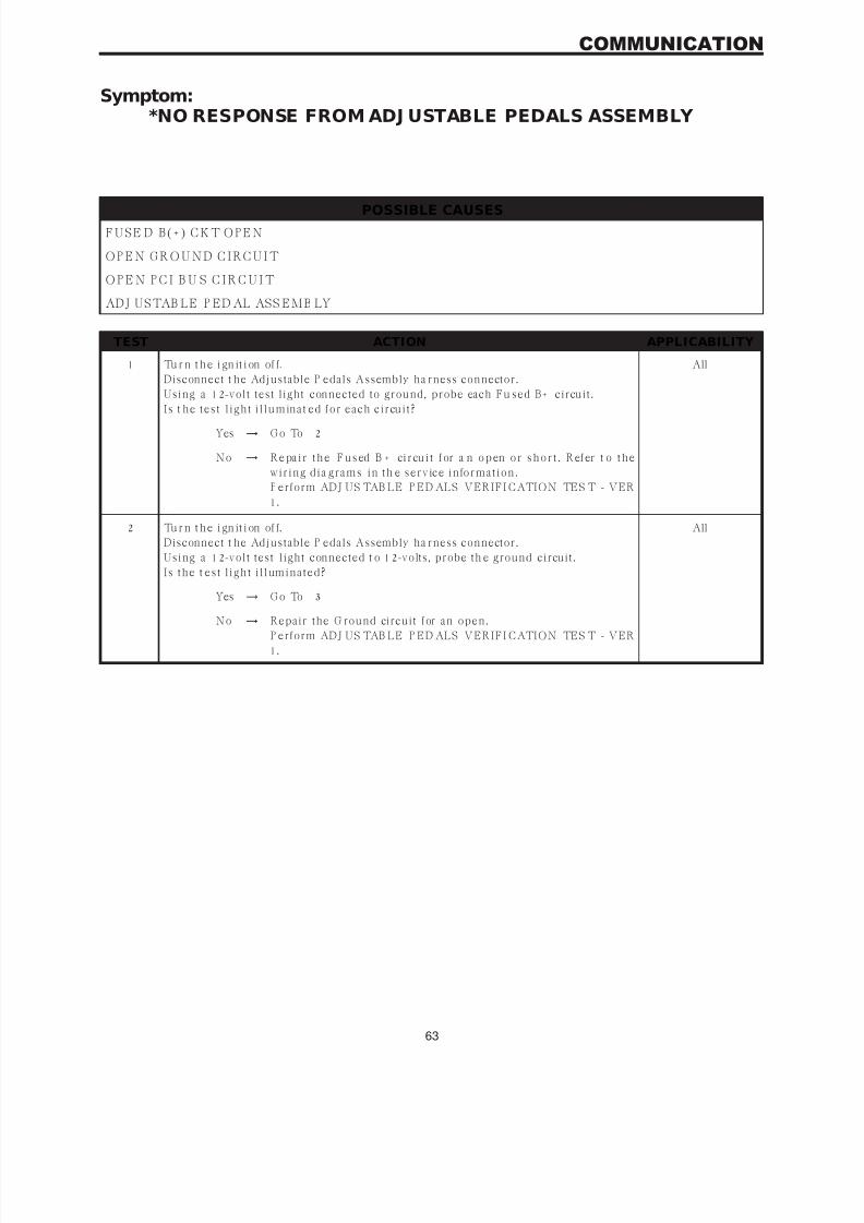
7/21/2019 2005 RS Chassis
http://slidepdf.com/reader/full/2005-rs-chassis 67/86
Symptom:*NO RESPONSE FROM ADJ USTABLE PEDALS ASSEMBLY
POSSIBLE CAUSES
F U S E D B ( + ) C K T O P E N
O P E N G R O U N D C I R C U I T
O P E N P C I B U S C I R C U I T
ADJ USTAB LE P ED AL ASS EMB LY
TEST ACTION APPLICABILITY
1 Tu r n t h e i gn it i on of f.
Disconnect t he Adjustable P edals Assembly ha rness connector.
Using a 12-volt test light connected to ground, probe each Fu sed B+ circuit .
I s t h e t es t l igh t i l lu min a t ed for ea ch cir cu it ?
All
Yes → G o To 2
No → R e pa i r t h e F u s ed B + ci r cu i t f or a n o p en o r s h o r t . R ef er t o t h e
w ir in g dia gr a ms in t h e s er v ice in for ma t ion .
P erform ADJ US TAB LE P ED ALS VERIFI CATION TES T - VER
1.
2 Tu r n t h e i gn it i on of f.
Disconnect t he Adjustable P edals Assembly ha rness connector.
Using a 12-volt test light connected t o 12-volts, probe th e ground circuit .
I s t h e t es t l igh t i l lumin a t ed?
All
Yes → G o To 3
No → Repair the G round circuit for an open.P erform ADJ US TAB LE P ED ALS VERIFI CATION TES T - VER
1.
63
COMMUNICATION

7/21/2019 2005 RS Chassis
http://slidepdf.com/reader/full/2005-rs-chassis 68/86
TEST ACTION APPLICABILITY
3 Note: Ensure there is PCI Bus communication with other modules on thevehicle before proceeding. If not, refer to the symptom list from the menuand repair as necessary.
Disconnect t he Adjustable P edals Assembly ha rness connector.U s e Scop e in p u t ca ble C H7058, C a ble t o P r obe a da p t er C H7062, a n d t h e r ed a n d
black test probes.
Connect the scope input cable to the channel one connector on the DRB. Attach the
r ed a n d bla ck lea ds a n d t h e ca ble t o p r obe a da p t er t o t h e s cop e in pu t ca ble.
W it h t h e DR B I I I select P ep Module Tools.
Select la b scope.
Select L iv e Da t a .
Select 12 v olt s qu a r e w a v e.
Press F2 for Scope.
P r e s s F 2 a n d u s e t h e d ow n a r r o w t o s et v ol t a g e r a n g e t o 2 0 v ol t s . P r e s s F 2 a g a i n
when complete.
C on n ect t h e B la ck lea d t o t h e ch a s s is gr ou n d. C on n ect t h e R ed lea d t o t h e P C I B u s
circuit in t he Adjustable P edals Assembly connector.
Turn the ignition on.Obs er v e t h e v olt a ge dis pla y on t h e D R B L a b Scop e.
Does the voltage pulse from 0 to approximately 7.5 volts?
All
Yes → R epla ce t h e Adjus t a ble P eda ls As s embly in a ccor da n ce w it h t h e
service informa tion.
P erform ADJ US TAB LE P ED ALS VERIFI CATION TES T - VER
1.
No → R epa ir t h e P C I B u s cir cu it for a n open .
P erform ADJ US TAB LE P ED ALS VERIFI CATION TES T - VER
1.
64
COMMUNICATION
*NO RE SPONSE FROM ADJ USTABLE PEDALS ASSEMBLY — Continued

7/21/2019 2005 RS Chassis
http://slidepdf.com/reader/full/2005-rs-chassis 69/86
Symptom:*NO RESPONSE FROM CONTROLLER ANTILOCK BRAKE
POSSIBLE CAUSES
N O RES PO N S E F RO M C A B
G R O U N D C I R C U I T O P E N
O PE N F U S E D I G N I TI O N S WI TC H O U TP U T C I RC U I T
O P E N P C I B U S C I R C U I T
CONTROLLER ANTILOCK BRAKE
TEST ACTION APPLICABILITY
1 Tu rn t h e ig ni ti on on .
Note: As soon as one or more module communicates with the DRB, answer
the question.With the DRB, attempt to communicate with the Airbag Control Module (ACM).
Wit h t h e DR B , a t t emp t t o commu n ica t e w it h t h e B ody C on t r ol M odu le (B C M ).
Was the D RB able t o I/D or establish communicat ions with either of the m odules?
All
Yes → G o To 2
No → Refer to the Communicat ions category and perform the symptom
P C I B u s C ommu n ica t ion Fa ilu r e.
P erform AB S VERIFI CATION TES T - VER 1.
2 Tu r n t h e i gn it i on of f.
Disconnect the CAB harness connector.
Using a 12-volt test light connected t o 12-volts, probe both ground circuits.
I s t h e t es t l igh t i l lu min a t ed for ea ch cir cu it ?
All
Yes → G o To 3
No → Repair th e ground circuit(s) for an open.
P erform AB S VERIFI CATION TES T - VER 1.
3 Tu r n t h e i gn it i on of f.
Disconnect the CAB harness connector.
Turn the ignition on.
U s in g a 12-v olt t es t l igh t con n ect ed t o gr ou n d, p r obe t h e Fu s ed I gn it ion S w it ch
Output circuit .
I s t h e t es t l igh t i l lumin a t ed?
All
Yes → G o To 4
No →
R epa ir t h e Fu s ed I gn it ion S w it ch Ou t p u t cir cu it for a n open .P erform AB S VERIFI CATION TES T - VER 1.
65
COMMUNICATION
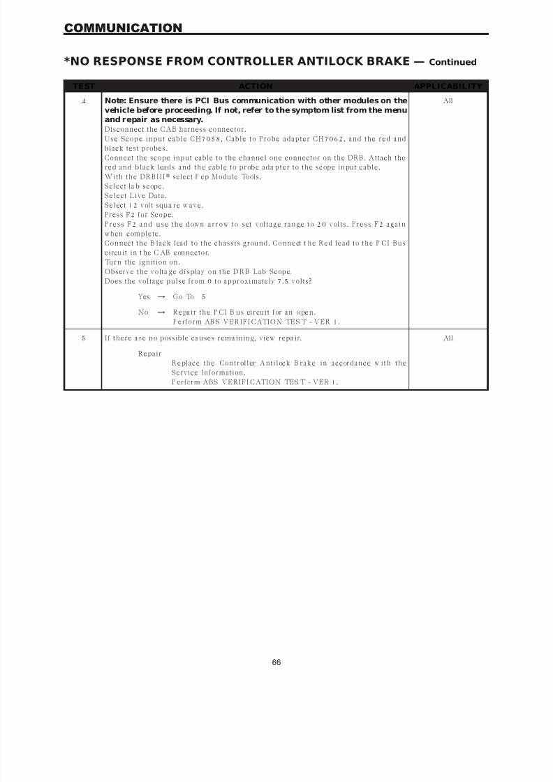
7/21/2019 2005 RS Chassis
http://slidepdf.com/reader/full/2005-rs-chassis 70/86
TEST ACTION APPLICABILITY
4 Note: Ensure there is PCI Bus communication with other modules on thevehicle before proceeding. If not, refer to the symptom list from the menuand repair as necessary.
Disconnect the CAB harness connector.U s e Scop e in p u t ca ble C H7058, C a ble t o P r obe a da p t er C H7062, a n d t h e r ed a n d
black test probes.
Connect the scope input cable to the channel one connector on the DRB. Attach the
r ed a n d bla ck lea ds a n d t h e ca ble t o p r obe a da p t er t o t h e s cop e in pu t ca ble.
W it h t h e DR B I I I select P ep Module Tools.
Select la b scope.
Select L iv e Da t a .
Select 12 v olt s qu a r e w a v e.
Press F2 for Scope.
P r e s s F 2 a n d u s e t h e d ow n a r r o w t o s et v ol t a g e r a n g e t o 2 0 v ol t s . P r e s s F 2 a g a i n
when complete.
C on n ect t h e B la ck lea d t o t h e ch a s s is gr ou n d. C on n ect t h e R ed lea d t o t h e P C I B u s
circuit in t he C AB connector.
Turn the ignition on.Obs er v e t h e v olt a ge dis pla y on t h e D R B L a b Scop e.
Does the voltage pulse from 0 to approximately 7.5 volts?
All
Yes → G o To 5
No → R epa ir t h e P C I B u s cir cu it for a n open .
P erform AB S VERIFI CATION TES T - VER 1.
5 I f t h er e a r e n o possible ca u ses r em a in in g, view r epa ir. All
Repair
R epla ce t h e C on t r oller A n t ilock B r a k e in a ccor da n ce w it h t h e
Service Information.
P erform ABS VERIFI CATION TES T - VER 1.
66
COMMUNICATION
*NO RESPONSE FROM CONTROLLER ANTILOCK BRAKE — Continued

7/21/2019 2005 RS Chassis
http://slidepdf.com/reader/full/2005-rs-chassis 71/86
Verification Tests
ABS VERIFICATION TEST - VER 1 APPLICABILITY
1. Turn th e ignit ion off.
2. Connect a ll previously disconnected components an d connectors.
3. E n s u r e a ll a cces sor ies a r e t u r n ed off a n d t h e ba t t er y is fu lly ch a r ged.
4. Ensur e tha t the Ign ition is on, an d wit h the DRB III , erase all Dia gnostic Trouble Codes from
AL L modu les . St a r t t h e en gin e a n d a llow it t o r u n for 2 min u t es a n d fu lly oper a t e t h e s ys t em
t h a t w a s ma lfu n ct ion in g.
5. Tu r n t h e ign it ion off a n d w a it 5 s econ ds . Tu r n t h e ign it ion on a n d u s in g t h e DR B I I I , r ea d
DTC’s from ALL modules.
6. If any Dia gnostic Trouble Codes ar e present, ret urn t o Symptom list a nd t roubleshoot new
or recurring symptom.
7. NOTE: For Sensor Signal and Pump Motor faults, the CAB must sense all 4 wheelsat 25 km/h (15 mph) before it will extinguish the ABS Indicator.8. I f t h er e a r e n o DTC ’s p r es en t a f t er t u r n in g ign it ion on , r oa d t es t t h e v eh icle for a t lea s t 5
minutes. Perform several antilock braking stops.
9. Caution: Ensure braking capability is available before road testing.10. Aga in , w it h t h e DR B I I I r ea d DTC ’ s. I f a n y DTC ’s a r e p r es en t , r et u r n t o Symp t om lis t .
11. If there a re no Dia gnost ic Trouble Codes (DTC’s) present , an d th e customer’s concern can n o
longer be duplicated, the repair is complete.Are any DTC’s present or is the original concern still present?
All
Yes → Repair is not complete, refer to appropriate symptom.
No → Repair is complete.
ADJ USTABL E PE DAL S VE RI FI CAT ION T EST - VE R 1 APPL I CABI LI TY
1. If the Adjustable P edals Module wa s replaced, progra m t wo pedal positions if equipped with
memory function.
2. Act iva t e t h e A dju s t a ble P eda ls t h r ou gh t h e fu ll r a n ge of mov emen t .
3. Verify that the Adjustable Pedals system is disabled with the vehicle in Reverse.
4. Ver ify t h a t t h e Adju s t a ble P eda ls s ys t em is dis a bled w it h S p eed C on t r ol a ct iv a t ed.
5. Wit h t h e DR B I I I, erase DTCs.
6. Wit h t h e DR B I I I, r ea d DTC s .Are any DTC’s present or is the original complaint still present?
All
Yes → Repair is not complete, refer to appropriate symptom.
No → Repair is complete.
67
VERIFICATION TESTS

7/21/2019 2005 RS Chassis
http://slidepdf.com/reader/full/2005-rs-chassis 72/86
NOTES
68

7/21/2019 2005 RS Chassis
http://slidepdf.com/reader/full/2005-rs-chassis 73/86
8.0 COMPONENT LOCATIONS
8. 1 CONTROLLER ANTILOCK BRAKE (CAB)
8. 2 DATA LINK CONNECTOR
8.3 FUSES
C
O
M
P
O
N
E
N
T
L
O
C
A
T
O
N
S
69
COMPONENT LOCATIONS

7/21/2019 2005 RS Chassis
http://slidepdf.com/reader/full/2005-rs-chassis 74/86
8. 4 TRACTION CONTROL SWITCH
8. 4. 1 TRACTION CONTROL INDICATORS
8. 5 WHEEL SPEED SENSORS
8.5.1 FRONT
C
O
M
P
O
N
E
N
T
L
O
C
A
T
I
O
N
S
70
COMPONENT LOCATIONS

7/21/2019 2005 RS Chassis
http://slidepdf.com/reader/full/2005-rs-chassis 75/86
8.5.2 REAR
8. 5A WHEEL SPEED SENSOR CONNECTORS
8.5A.1 FRONT
8.5A.2 REAR
C
O
M
P
O
N
E
N
T
L
O
C
A
T
O
N
S
71
COMPONENT LOCATIONS

7/21/2019 2005 RS Chassis
http://slidepdf.com/reader/full/2005-rs-chassis 76/86
8. 6 BRAKE LAM P SWITCHC
O
M
P
O
N
E
N
T
L
O
C
A
T
I
O
N
S
72
COMPONENT LOCATIONS
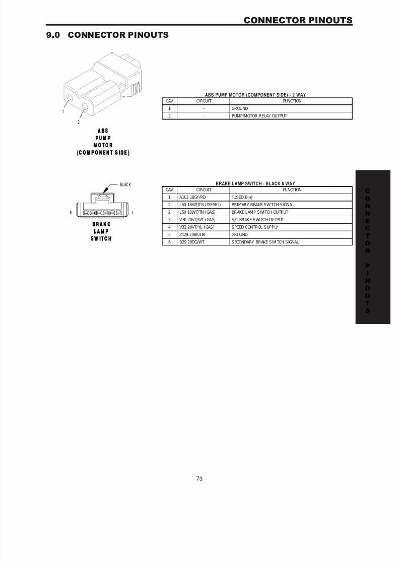
7/21/2019 2005 RS Chassis
http://slidepdf.com/reader/full/2005-rs-chassis 77/86
9.0 CONNECTOR PINOUTS
ABS PUMP MOTOR (COMPONENT SIDE) - 2 WAYCAV CIRCUIT FUNCTION
1 - GROUND
2 - PUMP/MOTOR RELAY OUTPUT
BRAKE LAMP SWITCH - BLACK 6 WAY
CAV CIRCUIT FUNCTION1 A103 18GY/RD FUSED B(+)
2 L50 18WT/TN (DIESEL) PRIMARY BRAKE SWITCH SIGNAL
2 L50 18WT/TN (GAS) BRAKE LAMP SWITCH OUTPUT
3 V30 20VT/WT (GAS) S/C BRAKE SWITCH OUTPUT
4 V32 20VT/YL (GAS) SPEED CONTROL SUPPLY
5 Z429 20BK/OR GROUND
6 B29 20DG/WT SECONDARY BRAKE SWITCH SIGNAL
CO
N
N
E
C
T
O
R
P
N
OU
T
S
73
CONNECTOR PINOUTS

7/21/2019 2005 RS Chassis
http://slidepdf.com/reader/full/2005-rs-chassis 78/86
CONTROLLER ANTILOCK BRAKE - BLACK 24 WAY
CAV CIRCUIT FUNCTION
1 Z107 12BK/DG GROUND
2 B1 18DG/OR RIGHT REAR WHEEL SPEED SENSOR SIGNAL
3 B2 18DG/LB RIGHT REAR WHEEL SPEED SENSOR 12 VOLT SUPPLY
4 - -
5 D25 18WT/VT PCI BUS
6 B6 18DG/WT RIGHT FRONT WHEEL SPEED SENSOR SIGNAL
7 B7 18DG/VT RIGHT FRONT WHEEL SPEED SENSOR 12 VOLT SUPPLY
8 - -
9 A111 12DG/RD FUSED B(+)
10 F500 18DG/PK FUSED IGNITION SWITCH OUTPUT (RUN)
11 - -
12 - -
13 - -
14 - -
15 - -
16 Z127 12BK/DG GROUND
17 - -
18 L50 18WT/TN (DIESEL) PRIMARY BRAKE SWITCH SIGNAL
18 L50 18WT/TN (GAS) BRAKE LAMP SWITCH OUTPUT
19 B3 18DG/YL LEFT REAR WHEEL SPEED SENSOR SIGNAL20 B4 18DG/GY LEFT REAR WHEEL SPEED SENSOR 12 VOLT SUPPLY
21 - -
22 B8 18DG/TN LEFT FRONT WHEEL SPEED SENSOR SIGNAL
23 B9 18DG/WT (3.3L/3.8L) LEFT FRONT WHEEL SPEED SENSOR 12 VOLT SUPPLY
23 B9 18DG/LG (EXCEPT
3.3L/3.8L)
LEFT FRONT WHEEL SPEED SENSOR 12 VOLT SUPPLY
24 A107 12TN/RD FUSED B(+)
DATA LINK CONNECTOR - BLACK 16 WAY
CAV CIRCUIT FUNCTION
1 - -
2 D25 20WT/VT PCI BUS
3 - -4 Z11 20BK/LG GROUND
5 Z111 20BK/WT GROUND
6 - -
7 D21 20WT/DG (DIESEL) SCI TRANSMIT (ECM)
7 D21 20WT/DG (GAS) SCI TRANSMIT (PCM)
8 - -
9 D123 20WT/BR FLASH PROGRAM ENABLE
10 - -
11 - -
12 D20 20WT/LG (GAS) SCI RECEIVE (PCM)
13 - -
14 - -
15 D15 20DG/YL (EATX) SCI TRANSMIT (TCM)
16 A105 20DB/RD FUSED B(+)
CO
N
N
E
C
T
O
R
P
I
N
OU
T
S
74
CONNECTOR PINOUTS

7/21/2019 2005 RS Chassis
http://slidepdf.com/reader/full/2005-rs-chassis 79/86
CO
N
N
E
C
T
O
R
P
N
OU
T
S
75
CONNECTOR PINOUTS

7/21/2019 2005 RS Chassis
http://slidepdf.com/reader/full/2005-rs-chassis 80/86
FUSES (IPM)FUSE
NO.
AMPS FUSED CIRCUIT FUNCTION
1 20A INTERNAL FUSED B(+)
2 15A INTERNAL FUSED PARK LAMP RELAY OUTPUT
3 15A INTERNAL FUSED PARK LAMP RELAY OUTPUT
4 30A INTERNAL FUSED B(+)
5 20A F306 16DB/PK FUSED ACCESSORY RELAY OUTPUT
6 20A F307 16LB/PK (ACCESSORY RELAY P OSITION) FUSED ACCESSORY RELAY OUTP UT
6 20A F307 16LB/PK (BATTERY POSITION) FUSED B(+)
8 20A INTERNAL FUSED B(+)
9 40A INTERNAL FUSED B(+)
10 40A C7 12DB FUSED FRONT BLOWER MOTOR RELAY OUTPUT
11 20A F302 18GY/PK FUSED ACCESSORY RELAY OUTPUT
12 25A C51 12LB/BR FUSED REAR BLOWER MOTOR RELAY OUTPUT
13 40A C15 12DB/WT FUSED DEFOGGER RELAY OUTPUT
14 20A INTERNAL FUSED B(+) (I.O.D.)
15 20A INTERNAL (DIESEL) FUSED B(+)
15 20A INTERNAL (EATX) FUSED B(+)
16 25A INTERNAL FUSED B(+)
17 20A INTERNAL FUSED B(+)
18 15A INTERNAL FUSED B(+)
19 40A A101 12VT/RD FUSED B(+)
20 30A A102 12WT/RD FUSED B(+)
21 25A A111 12DG/RD FUSED B(+)
22 40A A110 12OR/RD FUSED B(+)
23 10A A106 20LB/RD FUSED B(+)
24 20A A701 16BR/RD FUSED B(+) (HAZARD)
26 20A A103 18GY/RD FUSED B(+)
27 40A A112 12OR/RD FUSED B(+)
28 40A F30 12PK/YL FUSED IGNITION SWITCH OUTPUT (RUN-ACC)
30 40A INTERNAL (EXPORT) FUSED B(+)
31 40A A113 12WT/RD FUSED B(+)
32 40A A115 12YL/RD FUSED B(+)33 15A INTERNAL FUSED ACCESSORY RELAY OUTPUT
LEFT FRONT WHEEL SPEED SENSOR - GRAY 2 WAY
CAV CIRCUIT FUNCTION
1 B9 18DG/WT (3.3L/3.8L) LEFT FRONT WHEEL SPEED SENSOR 12 VOLT SUPPLY
1 B9 18DG/LG (EXCEPT
3.3L/3.8L)
LEFT FRONT WHEEL SPEED SENSOR 12 VOLT SUPPLY
2 B8 18DG/TN LEFT FRONT WHEEL SPEED SENSOR SIGNAL
CO
N
N
E
C
T
O
R
P
I
N
OU
T
S
76
CONNECTOR PINOUTS
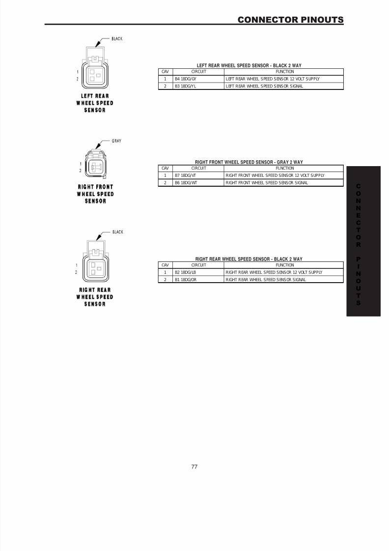
7/21/2019 2005 RS Chassis
http://slidepdf.com/reader/full/2005-rs-chassis 81/86
LEFT REAR WHEEL SPEED SENSOR - BLACK 2 WAY
CAV CIRCUIT FUNCTION
1 B4 18DG/GY LEFT REAR WHEEL SPEED SENSOR 12 VOLT SUPPLY
2 B3 18DG/YL LEFT REAR WHEEL SPEED SENSOR SIGNAL
RIGHT FRONT WHEEL SPEED SENSOR - GRAY 2 WAY
CAV CIRCUIT FUNCTION
1 B7 18DG/VT RIGHT FRONT WHEEL SPEED SENSOR 12 VOLT SUPPLY
2 B6 18DG/WT RIGHT FRONT WHEEL SPEED SENSOR SIGNAL
RIGHT REAR WHEEL SPEED SENSOR - BLACK 2 WAY
CAV CIRCUIT FUNCTION
1 B2 18DG/LB RIGHT REAR WHEEL SPEED SENSOR 12 VOLT SUPPLY
2 B1 18DG/OR RIGHT REAR WHEEL SPEED SENSOR SIGNAL
CO
N
N
E
C
T
O
R
P
N
OU
T
S
77
CONNECTOR PINOUTS

7/21/2019 2005 RS Chassis
http://slidepdf.com/reader/full/2005-rs-chassis 82/86
NOTES
78
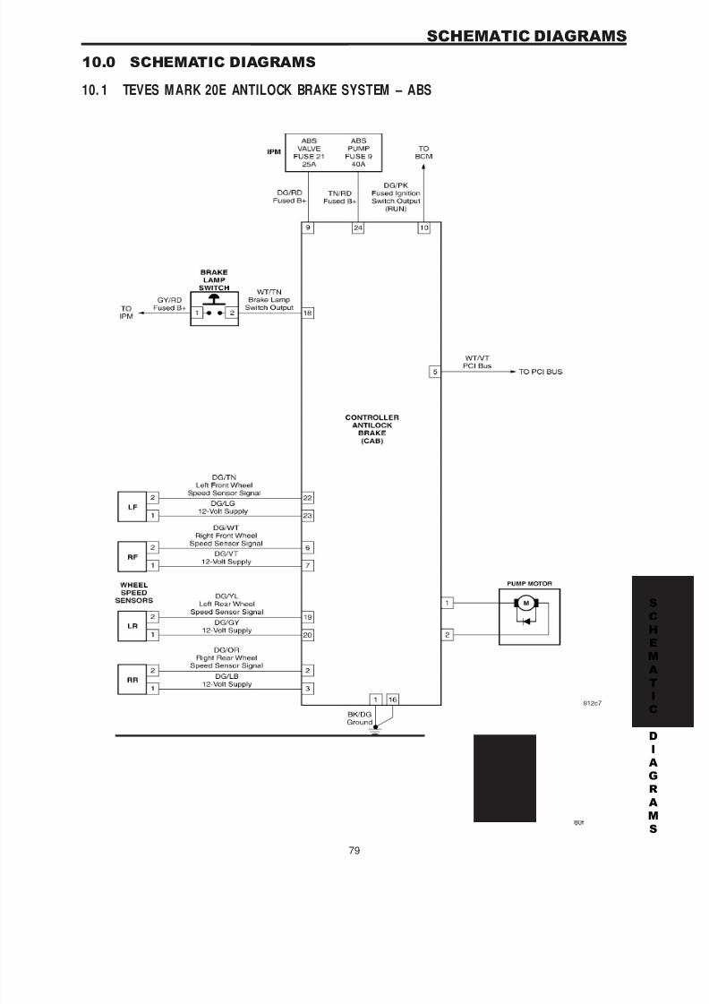
7/21/2019 2005 RS Chassis
http://slidepdf.com/reader/full/2005-rs-chassis 83/86
10.0 SCHEMATIC DIAGRAMS
10. 1 TEVES M ARK 20E ANTILOCK BRAKE SYSTEM – ABS
S
C
H
E
M
A
T
C
D
A
G
R
A
M
S
79
SCHEMATIC DIAGRAMS

7/21/2019 2005 RS Chassis
http://slidepdf.com/reader/full/2005-rs-chassis 84/86
NOTES
80
7/21/2019 2005 RS Chassis
http://slidepdf.com/reader/full/2005-rs-chassis 85/86
DIAGNOSTIC TEST PROCEDURES — TELL US!
DaimlerChrysler Corporation is constantly working to provide the technician the best diagnostic manuals possible.Your comments and recommendations regarding the diagnostic manuals and procedures are appreciated.
To best understand your suggestion, please complete the form giving us as much detail as possible.
Model Year Body Type Engine
Transmission Vehicle Mileage MDH
Diagnostic Procedure Book No. Page
Comments/recommendations (if necessary, draw sketch)
Name
Submitted by:
Address
City/State/Zip
Business Phone #
All comments become property of DaimlerChrysler Corporation and may be used without compensation.

7/21/2019 2005 RS Chassis
http://slidepdf.com/reader/full/2005-rs-chassis 86/86
Dealer Technical Operations800 Chrysler DriveCIMS 486-02-76Auburn Hills, MI 48326-2757


![Lg Tv 29fu6rsd[Rs] Chassis Cw62d, Service Manual](https://static.fdocuments.in/doc/165x107/55cf8e8e550346703b935c7e/lg-tv-29fu6rsdrs-chassis-cw62d-service-manual.jpg)