2005 CAT Engine Progrramming
184
description
the Ebook instruct user program CAT engine system
Transcript of 2005 CAT Engine Progrramming
Page 1Page 1Page 1Page 1Page 1
ContentsContentsContentsContentsContents
ContentsContentsContentsContentsContents
IntroductionIntroductionIntroductionIntroductionIntroduction ............................................................................................................................................................................................................................................................................................................................................................................................ 44444What’s New ............................................................................................. 5Understanding the Electronic Controls ........................................... 6Factory Specified Parameters and Features ................................. 8Customer Programmable Parameters and Specifications ......... 9Feature Comparison by Model ......................................................... 10Data Book and Optional Parameters .............................................. 13
Identification ParametersIdentification ParametersIdentification ParametersIdentification ParametersIdentification Parameters ............................................................................................................................................................................................................................................................... 1 51 51 51 51 5Vehicle ID ............................................................................................... 16
Vehicle Speed ParametersVehicle Speed ParametersVehicle Speed ParametersVehicle Speed ParametersVehicle Speed Parameters .......................................................................................................................................................................................................................................................... 1 71 71 71 71 7Vehicle Speed Calibration ................................................................. 18Vehicle Speed Calibration (J1939 Trans) ....................................... 20Vehicle Speed Calibration (J1939 ABS) .......................................... 21Vehicle Speed Limit (VSL) ................................................................... 22VSL Protection ...................................................................................... 24Tachometer Calibration ..................................................................... 25Soft Vehicle Speed Limit ..................................................................... 26Two-Speed Range Axle Ratio ........................................................... 28
Cruise Control ParametersCruise Control ParametersCruise Control ParametersCruise Control ParametersCruise Control Parameters .......................................................................................................................................................................................................................................................... 2 92 92 92 92 9Low Cruise Control Speed Set Limit ................................................. 31High Cruise Control Speed Set Limit ................................................ 32Engine Retarder ................................................................................... 33Engine Retarder Delay ....................................................................... 35Engine Retarder Minimum Vehicle Speed Limit Type ................. 36Engine Retarder Minimum Vehicle Speed .................................... 37Smart Idle Parameters ....................................................................... 38Auto Retarder in Cruise ...................................................................... 39Auto Retarder in Cruise Increment ................................................. 41Cruise/Idle/PTO Switch Configuration ............................................ 43SoftCruise Control ................................................................................ 44
Idle ParametersIdle ParametersIdle ParametersIdle ParametersIdle Parameters ............................................................................................................................................................................................................................................................................................................................................... 4 54 54 54 54 5Idle Vehicle Speed Limit ..................................................................... 46Idle RPM Limit ........................................................................................ 47Idle/PTO RPM Ramp Rate ................................................................... 48Idle/PTO Bump RPM ............................................................................ 49Fast Idle Engine #1 RPM ..................................................................... 50Fast Idle Engine #2 RPM ..................................................................... 50Warm Up Mode Idle Speed ............................................................... 51
Dedicated PTO ParametersDedicated PTO ParametersDedicated PTO ParametersDedicated PTO ParametersDedicated PTO Parameters ..................................................................................................................................................................................................................................................... 5 25 25 25 25 2PTO Configuration ............................................................................... 53PTO Top Engine Limit ........................................................................... 54PTO Engine RPM Set Speed .............................................................. 55PTO to Set Speed ................................................................................. 56PTO Cab Throttle RPM Limit ............................................................... 57PTO Kickout Vehicle Speed Limit ...................................................... 58Torque Limit ........................................................................................... 59PTO Shutdown Time ............................................................................ 60PTO Shutdown Timer Maximum RPM .............................................. 61PTO Activates Cooling Fan ................................................................ 62
Engine/Gear ParametersEngine/Gear ParametersEngine/Gear ParametersEngine/Gear ParametersEngine/Gear Parameters ......................................................................................................................................................................................................................................................................... 6 36 36 36 36 3Lower Gears Engine RPM Limit ........................................................ 64Lower Gears Turn Off Speed ............................................................ 64Intermediate Gears Engine RPM Limit ............................................ 64Intermediate Gears Turn Off Speed ................................................ 64Gear Down Protection RPM Limit ..................................................... 67

Page
2Pa
ge 2
Page
2Pa
ge 2
Page
2Co
nten
tsCo
nten
tsCo
nten
tsCo
nten
tsCo
nten
tsGear Down Protection Turn On Speed .......................................... 67Top Engine Limiting (TEL) ................................................................... 69Low Idle Engine RPM .......................................................................... 70Transmission Style ............................................................................... 71Eaton Top 2 Override with Cruise Switch ....................................... 72Eaton Top 2 Gear Ratios ..................................................................... 73GFRS/GFRSS .......................................................................................... 75AT/MT/HT Part Throttle Shift Speed ................................................ 77Governor Type ...................................................................................... 78
TTTTTimer Parametersimer Parametersimer Parametersimer Parametersimer Parameters ..................................................................................................................................................................................................................................................................................................................................... 8 08 08 08 08 0Idle Shutdown Timer ........................................................................... 81Allow Idle Shutdown Override .......................................................... 83Minimum Idle Shutdown Outside Temperature ........................... 85Maximum Idle Shutdown Outside Temperature .......................... 85A/C Pressure Switch Fan-On Time ................................................... 86Fan with Engine Retarder in High Mode ........................................ 87
Exhaust Brake ParametersExhaust Brake ParametersExhaust Brake ParametersExhaust Brake ParametersExhaust Brake Parameters ..................................................................................................................................................................................................................................................... 8 88 88 88 88 8Exhaust Brake Configuration ........................................................... 89
Engine Monitoring ParametersEngine Monitoring ParametersEngine Monitoring ParametersEngine Monitoring ParametersEngine Monitoring Parameters ....................................................................................................................................................................................................................... 9 09 09 09 09 0Engine Monitoring Mode ................................................................... 91Engine Monitoring Lamps .................................................................. 94Coolant Level Sensor .......................................................................... 95Coolant Temperature Derate ........................................................... 96Engine Oil Pressure Sensor .............................................................. 97Oil Level Switch Installation Status .................................................. 98Primary Fuel Tank Capacity ............................................................... 99Secondary Fuel Tank Capacity ...................................................... 100
Maintenance ParametersMaintenance ParametersMaintenance ParametersMaintenance ParametersMaintenance Parameters .......................................................................................................................................................................................................................................................... 101101101101101Maintenance Indicator Mode ........................................................ 102PM1 Interval ........................................................................................ 104Engine Oil Capacity ............................................................................ 105
TTTTTrip Parameters/Cat ID/Cat Messenger Accessrip Parameters/Cat ID/Cat Messenger Accessrip Parameters/Cat ID/Cat Messenger Accessrip Parameters/Cat ID/Cat Messenger Accessrip Parameters/Cat ID/Cat Messenger Access ............................................................ 107107107107107Fuel Correction Factor ..................................................................... 108Change Fuel Correction Factor ...................................................... 110PM1 Reset ............................................................................................ 111Fleet Trip Reset ................................................................................... 112Customer Parameters ...................................................................... 113State Selection ................................................................................... 114Quick Stop Rate .................................................................................. 115Theft Deterrent .................................................................................. 116Theft Deterrent Password .............................................................. 117
Input SelectionInput SelectionInput SelectionInput SelectionInput Selection ............................................................................................................................................................................................................................................................................................................................................... 118118118118118Transmission Neutral Switch .......................................................... 119Exhaust Brake Switch ...................................................................... 120Torque Limit Switch ........................................................................... 121Ignore Brake/Clutch Switch ........................................................... 122Two-Speed Axle Switch ................................................................... 123Diagnostic Enable Switch ................................................................ 124PTO On/Off Switch ............................................................................. 125PTO Engine Shutdown Switch ........................................................ 126PTO Engine RPM Set Speed Input A ............................................. 127PTO Engine RPM Set Speed Input B ............................................. 128Remote PTO Set Switch .................................................................... 129Remote PTO Resume Switch ........................................................... 130Cruise Control On/Off Switch ........................................................... 131Cruise Control Set/Resume Switch ................................................ 132Cruise Control Pause Switch ........................................................... 133A/C High Pressure Switch ................................................................ 134A/C Fan Request Switch ................................................................... 135Vehicle Speed Input .......................................................................... 136Fan Override Switch .......................................................................... 137Service Brake Pedal Position Switch #1 ....................................... 138
Page 3Page 3Page 3Page 3Page 3
Clutch Pedal Position Switch ........................................................... 139Starting Aid On/Off Switch ............................................................... 140Retarder Off/Low/Med/High Switch .............................................. 141
Output SelectionOutput SelectionOutput SelectionOutput SelectionOutput Selection ................................................................................................................................................................................................................................................................................................................................ 142142142142142Fast Idle Enabled Lamp .................................................................... 143Wait to Start Lamp ............................................................................. 144Fan Control Type ................................................................................ 145Change Oil Lamp ................................................................................ 146PTO Active Configuration Output ................................................... 147PTO Switch On Lamp ......................................................................... 148Engine Running Output .................................................................... 149Starting Aid Output ............................................................................ 150Engine Shutdown Output ................................................................ 151Auxiliary Brake ................................................................................... 152Air Inlet Shutoff Control Relay ......................................................... 153
Customer PasswordsCustomer PasswordsCustomer PasswordsCustomer PasswordsCustomer Passwords ........................................................................................................................................................................................................................................................................................ 154154154154154Customer Password #1 ..................................................................... 155Customer Password #2 ..................................................................... 155
Data Link ParametersData Link ParametersData Link ParametersData Link ParametersData Link Parameters ........................................................................................................................................................................................................................................................................................ 156156156156156Powertrain Data Link ........................................................................ 157
Special ParametersSpecial ParametersSpecial ParametersSpecial ParametersSpecial Parameters ....................................................................................................................................................................................................................................................................................................... 158158158158158Customer Parameter Lockout ........................................................ 159
TTTTTrip Datarip Datarip Datarip Datarip Data ................................................................................................................................................................................................................................................................................................................................................................................................. 160160160160160Current Totals ..................................................................................... 161Fleet Trip Totals ................................................................................... 162Driver Trip Totals ................................................................................ 163Histograms .......................................................................................... 164Custom Data ........................................................................................ 165
Miscellaneous InformationMiscellaneous InformationMiscellaneous InformationMiscellaneous InformationMiscellaneous Information ........................................................................................................................................................................................................................................... 167167167167167Multi-Torque Ratings ........................................................................ 168Triggering Snapshots ....................................................................... 170Cat ID/Messenger ............................................................................. 171Fleet Information Software .............................................................. 172Cat® Design Pro .................................................................................. 173Driver Reward .................................................................................... 174
Improving Fuel EconomyImproving Fuel EconomyImproving Fuel EconomyImproving Fuel EconomyImproving Fuel Economy ............................................................................................................................................................................................................................................................... 175175175175175Trip Preparation Tips ......................................................................... 176Driving Tips .......................................................................................... 177Spec’ing Recommendations ........................................................... 178
IndexIndexIndexIndexIndex ............................................................................................................................................................................................................................................................................................................................................................................................................................... 179179179179179
ContentsContentsContentsContentsContents

Page
4Pa
ge 4
Page
4Pa
ge 4
Page
4IntroductionIntroductionIntroductionIntroductionIntroduction
By the early 1980’s, it had become evident that newengine technologies would have to be brought to bearif Caterpillar, or any other diesel engine manufacturer,was to prosper in the rapidly evolving market environ-ment. A combination of increased governmentregulation, prompted by legitimate environmentalconcerns, stronger competition and more demandingmarket expectations dictated totally new approachesto diesel engine design.
In order to meet these challenges, Caterpillar em-barked on an ambitious development program tocreate totally new diesel engines. That programresulted in the 3176 and the 3406B PEEC. Since 1987,the use of electronics on Caterpillar On-HighwayEngines © has grown Engine models such as the C-10, C-12, C15, C-16, and 3126E have been introduced.Most recently, the model year 2004 electronic engineline includes the C7, C9, C11, C13, and C15 withACERT © Technology (Cat manufactures a widevariety of electronic engines for applications as variedas locomotives and very large earth movers. Thisbooklet covers On-Highway Engines only).
Today, electronics do much more than control thecombustion process to meet ever-toughening emissionstandards and customer fuel economy expectations.They allow the engine to talk to and coordinate withdriveline components. They allow monitoring andcontrol of driving habits to meet business objectives.Remote programming and monitoring ability allows realtime fleet control from an office location. In today’schanging economic environment, a fleet managermust juggle economy and driver satisfaction. Caterpil-lar electronically controlled engines allow a fleetmanager to spec a driveline free from the usualcompromises and then program the engines to reflectdesired driving habits. In addition, the Driver Rewardfeature allows the manager to automatically rewarddrivers who meet preset fleet objectives.
Incorporation of the latest, most powerful ECM,ADEM2000, has equipped Caterpillar On-HighwayEngines with numerous electronic features. This bookoutlines Caterpillar electronic features that have theability to change the way fleets operate. It is nowpossible to program fleet truck engines and sit backand let the electronics take over.
IntroductionIntroductionIntroductionIntroductionIntroductionIn
trod
uctio
nIn
trod
uctio
nIn
trod
uctio
nIn
trod
uctio
nIn
trod
uctio
n

Page 5Page 5Page 5Page 5Page 5
What’s NewWhat’s NewWhat’s NewWhat’s NewWhat’s New
A lot has changed with Caterpillar’s on-highwayengine technology since the last revision of this bookin January 2000. Perhaps the biggest change in Cat’son-highway engine technology has been the introduc-tion and perfection of ACERT © Technology. Thisbook essentially picks up where the January 2000revision left off, covering all on-highway engines from2001 to 2005. The Recommendations, Advantages, andDisadvantages sections have all been updated toreflect the most current line of Caterpillar on-highwayengines as well. What follows is a brief list of themajor additions and changes that have been made tothis book.
✔ All of the electronic parameters have beenmodified to reflect programming requirements foron-highway engines from 2001 up to 2005 includ-ing all necessary ACERT© Technology consider-ations.
✔ An Input Selection section had been added toprovide information on all available selectionoptions.
✔ The Output Selection section has been expandedto include more available outputs.
✔ Information on Gear Fast/Run Slow and Gear Fast/Run Super Slow has been added.
✔ Design Pro has replaced Truck Engine Pro.
✔ Cat Messenger has been referenced along withCat ID, since although Messenger is the newerdevice, both are in use today.
✔ Driver Reward information has been added.
✔ A section on Improving Fuel Economy has beenadded to provide helpful trip preparation, driving,and spec’ing recommendations for trucks pow-ered with Caterpillar on-highway engines withACERT© Technology.
IntroductionIntroductionIntroductionIntroductionIntroduction

Page
6Pa
ge 6
Page
6Pa
ge 6
Page
6In
trod
uctio
nIn
trod
uctio
nIn
trod
uctio
nIn
trod
uctio
nIn
trod
uctio
nUnderstanding the Electronic ControlsUnderstanding the Electronic ControlsUnderstanding the Electronic ControlsUnderstanding the Electronic ControlsUnderstanding the Electronic Controls
This booklet is to aid you in choosing appropriateprogrammable values. Some features fall into a “non-programmable” or “programmable only by yourauthorized Cat dealer” category. While you may notneed to be concerned about programming theseparameters, we have included them in this booklet soyou can have a greater understanding of the Caterpil-lar electronic system.
Cat electronic truck engines offer a wide range offeatures, these include but are not limited to:
✔ Maximum Vehicle Speed Limiting
✔ Maximum Engine RPM Limiting
✔ Progressive Shift prompts
✔ Idle-Shutdown Timer
✔ Wide variety of Cruise Control features
✔ Retarder control
✔ Dedicated PTO control features
✔ Engine Monitoring System
✔ Engine Diagnostics w/fault logging including“snapshot” recording
✔ Numerous Trip Recording options
✔ Powertrain (J1922 or J1939) Interface
✔ ATA (J1587) Data Link
✔ Cooling fan control including A/C high pressure
Not all of these features fall into the “customerprogrammable” category. Some features, like the ATAData Link, have to do with the way the engine elec-tronics are integrated into the truck and drive trainelectronics. Another example is the setting fortachometer calibration, which comes preset from thetruck factory and should not be changed. (In fact,most features come with a preset value from thefactory.)
Other features, like password protection, can only beset by a customer.
Page 7Page 7Page 7Page 7Page 7
IntroductionIntroductionIntroductionIntroductionIntroduction
In short, the programmable features fall into two basiccategories:
Factory specified parameters and featureswhich include both;1 – Caterpillar Standard FeaturesCaterpillar Standard FeaturesCaterpillar Standard FeaturesCaterpillar Standard FeaturesCaterpillar Standard Features2 – Truck Manufacturers’ (OEM) StandardTruck Manufacturers’ (OEM) StandardTruck Manufacturers’ (OEM) StandardTruck Manufacturers’ (OEM) StandardTruck Manufacturers’ (OEM) Standard
FeaturesFeaturesFeaturesFeaturesFeatures
Customer specified parameters and specifica-tions which include both;1 – OEM Databook Features OEM Databook Features OEM Databook Features OEM Databook Features OEM Databook Features (the ones
chosen as the truck is spec’d and ordered)
2 – Optional Programmable Features Optional Programmable Features Optional Programmable Features Optional Programmable Features Optional Programmable Features (parameters unique to the application
and normally set after the truck is delivered)
Customer programmable features with a icon inthe title bar can be locked for additional security. (SeeCustomer Parameter Lockout, page 159 for details.)
Note: Since the introduction of the 3176B and 3406Eengines in 1993, Caterpillar has continued to add andenhance the features available to both the FleetOwner and the Owner Operator. These additions andenhancements are made by changing the software inthe Personality Module, which is in the ElectronicControl Module (ECM) on the engine. New PersonalityModule Software can be installed by an authorizedCaterpillar dealer. Throughout this booklet referencesare made to software release dates to define when aparticular feature became available. Listed below arethe dates of the major Personality Module Softwareupdates.
These dates may or may not correspond to model yearchanges.
emaN etaD
00VON 0002rebmevoN
10TCO 1002rebotcO
20NAJ 2002yraunaJ
20TCO 2002rebotcO
30RAM 3002hcraM
40RAM 4002hcraM

Page
8Pa
ge 8
Page
8Pa
ge 8
Page
8Factory Specified Parameters andFactory Specified Parameters andFactory Specified Parameters andFactory Specified Parameters andFactory Specified Parameters andFeaturesFeaturesFeaturesFeaturesFeatures
Each new engine will come with several features setat factory default settings. Some of these, like the oilsump capacity, are set at the engine factory. Others,like the tachometer calibration, are set by the truckmanufacturer. All of these default settings fall intoone of three categories.
11111 – A specific value required by the engine or truckelectronics for proper operation (example - oilsump capacity, tachometer calibration)
22222 – A standard value set for convenience (example -PTO Ramp Rate is set at 50 rpm/sec)
33333 – A value set at the upper limit of the possible rangeto ensure that the specific feature does not takeeffect until reset by the customer (example -Vehicle Speed Limiting is set at 127 mph)
Intr
oduc
tion
Intr
oduc
tion
Intr
oduc
tion
Intr
oduc
tion
Intr
oduc
tion

Page 9Page 9Page 9Page 9Page 9
Customer Programmable Parameters andCustomer Programmable Parameters andCustomer Programmable Parameters andCustomer Programmable Parameters andCustomer Programmable Parameters andSpecificationsSpecificationsSpecificationsSpecificationsSpecifications
Determining Parameters and SpecificationsDetermining Parameters and SpecificationsDetermining Parameters and SpecificationsDetermining Parameters and SpecificationsDetermining Parameters and SpecificationsOn the following pages you will see a explanation ofeach electronic parameter. Along with the explana-tions are helpful recommendations and in some cases,split chart examples to help in specification develop-ment. Another aid in determining Parameters andSpecifications is Cat® Design Pro (See page 173).
Customer specified parameters are divided into twosections; OEM Data Book Programmable FeaturesOEM Data Book Programmable FeaturesOEM Data Book Programmable FeaturesOEM Data Book Programmable FeaturesOEM Data Book Programmable Features areused to spec and order a truck and the OptionalOptionalOptionalOptionalOptionalProgrammable FeaturesProgrammable FeaturesProgrammable FeaturesProgrammable FeaturesProgrammable Features are used to customize theengine for your operation.
Some OEM Data Book Programmable FeaturesSome OEM Data Book Programmable FeaturesSome OEM Data Book Programmable FeaturesSome OEM Data Book Programmable FeaturesSome OEM Data Book Programmable Featurescovered are: (see page 13 for complete listing)covered are: (see page 13 for complete listing)covered are: (see page 13 for complete listing)covered are: (see page 13 for complete listing)covered are: (see page 13 for complete listing)
❑ Vehicle Speed Limit (VSL)
❑ Cruise Control Parameters
❑ Engine/Gear Parameters
❑ PTO/Fast Idle Features
❑ Idle Shutdown Timer
❑ Retarder Control
❑ Tamper Resistance
❑ Password Protection
❑ Engine Monitoring System
Optional Programmable Specifications coveredOptional Programmable Specifications coveredOptional Programmable Specifications coveredOptional Programmable Specifications coveredOptional Programmable Specifications coveredinclude, bit are not limited to: (see page 13 forinclude, bit are not limited to: (see page 13 forinclude, bit are not limited to: (see page 13 forinclude, bit are not limited to: (see page 13 forinclude, bit are not limited to: (see page 13 forcomplete listing)complete listing)complete listing)complete listing)complete listing)
❑ Vehicle ID (required for Caterpillar fleet manage-ment software)
❑ Dedicated PTO Features
❑ Fuel Usage Correction Factor (ECM vs measured)
❑ Oil Capacity Adjustment for Maintenance Indica-tor
❑ Customer Specified PM Interval for MaintenanceIndicator
❑ Programmable Low Idle RPM
IntroductionIntroductionIntroductionIntroductionIntroduction

Page
10
Page
10
Page
10
Page
10
Page
10
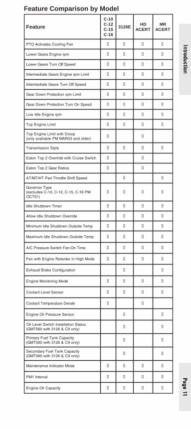
Feature Comparison by ModelIn
trod
uctio
nIn
trod
uctio
nIn
trod
uctio
nIn
trod
uctio
nIn
trod
uctio
n
erutaeF
01-C21-C51-C61-C
E6213DH
TRECARM
TRECA
DIelciheV � � � �
noitarbilaCdeepSelciheV � � � �
timiLdeepSelciheV � � � �
noitcetorPLSV � � � �
noitarbilaCretemohcaT � � � �
timiLdeepSelciheVtfoS � � � �
oitaRelxAegnaRdeepS-owT � � � �
timiLdeepSteSlortnoCesiurCwoL � � � �
timiLdeepSteSlortnoCesiurChgiH � � � �
redrateRenignE � � � �
yaleDredrateRenignE � �
muminiMredrateRenignEepyTtimiLdeepSelciheV
� �
deepSelihceVmuminiMredrateRenignE � �
sretemaraPeldItramS � � � �
esiurCniredrateRotuA � � � �
tnemercnIesiurCniredrateRotuA � � � �
noitarugifnoChctiwSOTP/eldI/esiurC � � � �
lortnoCesiurCtfoS � � � �
timiLdeepSelciheVeldI � � � �
timiLmpreldI � � � �
etaRpmaRmprOTP/eldI � � � �
etaRpmuBmprOTP/eldI � � � �
1#mprenignEeldItsaF � �
2#mprenignEeldItsaF � �
deepSeldIedoMpUmraW � �
noitarugifnoCOTP � � � �
timiLenignEpoTOTP � � � �
deepSteSmprenignEOTP � � � �
deepSteSotOTP � � � �
timiLmprelttorhTbaCOTP � � � �
timiLdeepSelciheVOTP � � � �
timiLeuqroT � � � �
remiTnwodtuhSOTP � � � �
Page 11Page 11Page 11Page 11Page 11
Feature Comparison by ModelIntroductionIntroductionIntroductionIntroductionIntroduction
erutaeF
01-C21-C51-C61-C
E6213DH
TRECARM
TRECA
naFgnilooCsetavitcAOTP � � � �
mprenignEsraeGrewoL � � � �
deepSffOnruTsraeGrewoL � � � �
timiLmprenignEsraeGetaidemretnI � � � �
deepSffOnruTsraeGetaidemretnI � � � �
timiLmprnoitcetorPnwoDraeG � � � �
deepSnOnruTnoitcetorPnwoDraeG � � � �
mprenignEeldIwoL � � � �
timiLenignEpoT � � � �
poorDhtiwtimiLenignEpoT)redlodna30RAMMPelbaliavaylno(
� �
elytSnoissimsnarT � � � �
hctiwSesiurChtiwedirrevO2poTnotaE � �
soitaRraeG2poTnotaE � �
deepStfihSelttorhTtraPTH/TM/TA � �
epyTronrevoGMP61-C,51-C,21-C,01-Csedulcxe(
)10TCO� � � �
remiTnwodtuhSeldI � � � �
edirrevOnwodtuhSeldIwollA � � � �
pmeTedistuOnwodtuhSeldImuminiM � � � �
pmeTedistuOnwodtuhSeldImumixaM � � � �
emiTnO-naFhctiwSerusserPC/A � � � �
edoMhgiHniredrateRenignEhtiwnaF � � � �
noitarugifnoCekarBtsuahxE � �
edoMgnirotinoMenignE � � � �
rosneSleveLtnalooC � � � �
etareDerutarepmeTtnalooC � �
rosneSerusserPliOenignE � �
sutatSnoitallatsnIhctiwSleveLliO)ylno9C&6213htiw065TMG(
� �
yticapaCknaTleuFyramirP)ylno9C&6213htiw065TMG(
� �
yticapaCknaTleuFyradnoceS)ylno9C&6213htiw065TMG(
� �
edoMrotacidnIecnanetniaM � � � �
lavretnI1MP � � � �
yticapaCliOenignE � � � �

Page
12
Page
12
Page
12
Page
12
Page
12
Intr
oduc
tion
Intr
oduc
tion
Intr
oduc
tion
Intr
oduc
tion
Intr
oduc
tion
Feature Comparison by Model
erutaeF
01-C21-C51-C61-C
E6213DH
TRECARM
TRECA
)sseccAhsaD(teseR1MP � � � ��
)sseccAhsaD(teseRpirTteelF � �
tnerreteDtfehT � � � �
drowssaPtnerreteDtfehT � � � �
etaRpotSkciuQ � � � �
)sseccAhsaD(sretemaraPremotsuC � �
)sseccAhsaD(noitceleSetatS � �
rotcaFnoitcerroCleuF � �
rotcaFnoitcerroCleuFegnahC)sseccAhsaD(
� �
Page 13Page 13Page 13Page 13Page 13
Data Book and Optional ParametersData Book and Optional ParametersData Book and Optional ParametersData Book and Optional ParametersData Book and Optional Parameters
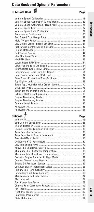
OEM Data BookOEM Data BookOEM Data BookOEM Data BookOEM Data Book PagePagePagePagePage
Vehicle Speed Calibration ................................................................. 18Vehicle Speed Calibration (J1939 Trans) ....................................... 20Vehicle Speed Calibration (J1939 ABS) .......................................... 21Vehicle Speed Limit ............................................................................. 22Vehicle Speed Limit Protection ........................................................ 24Tachometer Calibration ..................................................................... 25Two Speed Axle Range Ratio ............................................................ 28Multi-Torque Ratios ........................................................................... 168Low Cruise Control Speed Set Limit ................................................. 31High Cruise Control Speed Set Limit ................................................ 32Engine Retarder ................................................................................... 33Soft Cruise Control ............................................................................... 44Idle Shutdown Timer ........................................................................... 81Idle RPM Limit ........................................................................................ 47Lower Gears RPM Limit ....................................................................... 64Lower Gears Turn-Off Speed ........................................................... 64Intermediate Gears RPM Limit .......................................................... 64Intermediate Gears Turn-Off Speed ............................................... 64Gear Down Protection RPM Limit ..................................................... 67Gear Down Protection Turn-On Speed ......................................... 67Top Engine Limit .................................................................................... 69Eaton Top 2 Override with Cruise Switch ....................................... 72Governor Type ...................................................................................... 78Warm Up Mode Idle Speed ............................................................... 51Exhaust Brake Configuration ........................................................... 89Engine Monitoring Mode ................................................................... 91Engine Monitoring Lamps .................................................................. 94Coolant Level Sensor .......................................................................... 95Password #1 ........................................................................................ 155Password #2 ........................................................................................ 155
OptionalOptionalOptionalOptionalOptional PagePagePagePagePageVehicle ID ............................................................................................... 16Soft Vehicle Speed Limit ..................................................................... 26Engine Retarder Delay ....................................................................... 35Engine Retarder Minimum VSL Type ............................................... 36Auto Retarder in Cruise ...................................................................... 39Auto Retarder in Cruise Increment ................................................. 41Fast Idle RPM #1 & #2 ........................................................................... 50Dedicated PTO Parameters .............................................................. 52Low Idle Engine RPM .......................................................................... 70Allow Idle Shutdown Override .......................................................... 83Minimum Idle Shutdown Temperature ........................................... 85Maximum Idle Shutdown Temperature ......................................... 85Fan with Engine Retarder in High Mode ........................................ 87Coolant Temperature Derate ........................................................... 96Engine Oil Pressure Sensor .............................................................. 97Oil Level Switch Installation Status .................................................. 98Primary Fuel Tank Capacity ............................................................... 99Secondary Fuel Tank Capacity ...................................................... 100Maintenance Indicator Mode ........................................................ 102PM1 Interval ........................................................................................ 104Fuel Correction Factor ..................................................................... 108Change Fuel Correction Factor ...................................................... 110PM1 Reset ............................................................................................ 111Fleet Trip Reset ................................................................................... 112Customer Parameters ...................................................................... 113State Selection ................................................................................... 114
IntroductionIntroductionIntroductionIntroductionIntroduction
Page
14
Page
14
Page
14
Page
14
Page
14
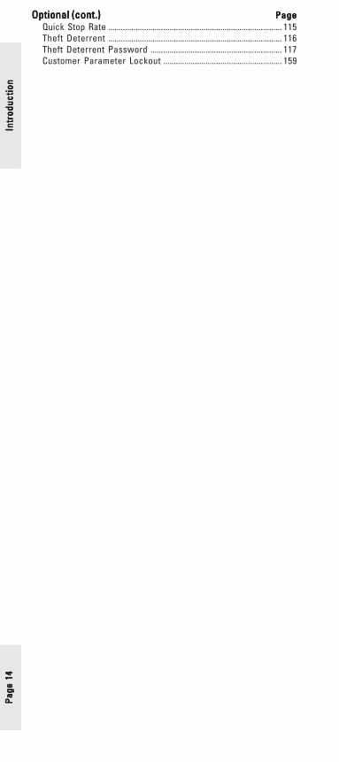
Optional (cont.)Optional (cont.)Optional (cont.)Optional (cont.)Optional (cont.) PagePagePagePagePageQuick Stop Rate .................................................................................. 115Theft Deterrent .................................................................................. 116Theft Deterrent Password .............................................................. 117Customer Parameter Lockout ........................................................ 159
Intr
oduc
tion
Intr
oduc
tion
Intr
oduc
tion
Intr
oduc
tion
Intr
oduc
tion

Page 15Page 15Page 15Page 15Page 15
Identification Parameters
Factory Databook Optional
• Vehicle ID .................................. ✔
IdentificationIdentificationIdentificationIdentificationIdentification
Page
16
Page
16
Page
16
Page
16
Page
16
Vehicle ID
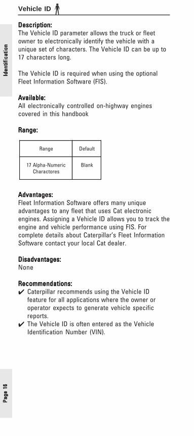
Description:Description:Description:Description:Description:The Vehicle ID parameter allows the truck or fleetowner to electronically identify the vehicle with aunique set of characters. The Vehicle ID can be up to17 characters long.
The Vehicle ID is required when using the optionalFleet Information Software (FIS).
Available:Available:Available:Available:Available:All electronically controlled on-highway enginescovered in this handbook
Range:Range:Range:Range:Range:
Advantages:Advantages:Advantages:Advantages:Advantages:Fleet Information Software offers many uniqueadvantages to any fleet that uses Cat electronicengines. Assigning a Vehicle ID allows you to track theengine and vehicle performance using FIS. Forcomplete details about Caterpillar’s Fleet InformationSoftware contact your local Cat dealer.
Disadvantages:Disadvantages:Disadvantages:Disadvantages:Disadvantages:None
Recommendations:Recommendations:Recommendations:Recommendations:Recommendations:✔ Caterpillar recommends using the Vehicle ID
feature for all applications where the owner oroperator expects to generate vehicle specificreports.
✔ The Vehicle ID is often entered as the VehicleIdentification Number (VIN).
Iden
tific
atio
nId
entif
icat
ion
Iden
tific
atio
nId
entif
icat
ion
Iden
tific
atio
n
egnaR tluafeD
ciremuN-ahplA71serotcarahC
knalB
Page 17Page 17Page 17Page 17Page 17
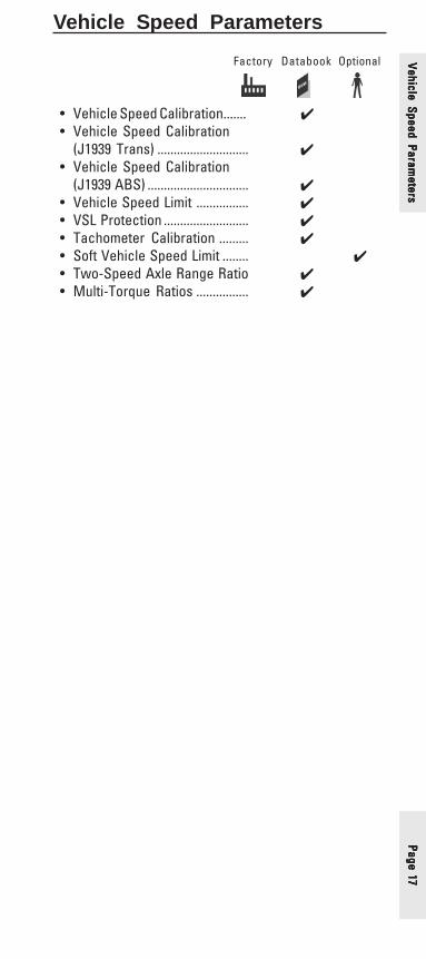
Vehicle Speed Parameters
Factory Databook Optional
• Vehicle Speed Calibration....... ✔• Vehicle Speed Calibration
(J1939 Trans) ............................ ✔• Vehicle Speed Calibration
(J1939 ABS) ............................... ✔• Vehicle Speed Limit ................ ✔• VSL Protection .......................... ✔• Tachometer Calibration ......... ✔• Soft Vehicle Speed Limit ........ ✔• Two-Speed Axle Range Ratio ✔• Multi-Torque Ratios ................ ✔
Vehicle Speed Parameters
Vehicle Speed Parameters
Vehicle Speed Parameters
Vehicle Speed Parameters
Vehicle Speed Parameters

Page
18
Page
18
Page
18
Page
18
Page
18
Vehicle Speed Calibration
Description:Description:Description:Description:Description:The value (Pulses per Mile, PPM) of this parameter isused by the ECM to convert the vehicle speed signalinto miles per hour (or kilometers per hour). The valueis calculated using tire revolutions per mile, rear axleratio and the number of teeth on the transmissionchopper wheel. This parameter is programmed by theOEM.
PPM = M x Ra x NExample: 31,200 = 502 x 3.90 x 16
M = Tire revolutions per mile. This information isavailable from the tire manufacturer.
Ra = Rear Axle Ratio. This is typically found on thehousing of the rear axle, or on the specificationsheet for the vehicle
N = Number of chopper teeth on the transmissiondrive shaft where the magnetic pickup is mounted.The value is typically 16, but may be 11.
Available:Available:Available:Available:Available:All electronically controlled on-highway engines
Range:Range:Range:Range:Range:
Advantages:Advantages:Advantages:Advantages:Advantages:Proper calculation of the Vehicle Speed Calibrationparameter is essential for proper cruise control andspeedometer (if controlled by the ECM) operation, andaccurate Fleet and Driver Trip Data.
Disadvantages:Disadvantages:Disadvantages:Disadvantages:Disadvantages:Miscalculation of the Vehicle Speed Calibrationparameter will cause all values calculated by the ECMusing the Vehicle Speed value to be in error (e.g.vehicle miles, fuel economy, etc.). Precise calculationPrecise calculationPrecise calculationPrecise calculationPrecise calculationis critical to provide accurate calculated values fromis critical to provide accurate calculated values fromis critical to provide accurate calculated values fromis critical to provide accurate calculated values fromis critical to provide accurate calculated values fromthe ECM.the ECM.the ECM.the ECM.the ECM.
Vehi
cle
Spee
d Pa
ram
eter
sVe
hicl
e Sp
eed
Para
met
ers
Vehi
cle
Spee
d Pa
ram
eter
sVe
hicl
e Sp
eed
Para
met
ers
Vehi
cle
Spee
d Pa
ram
eter
s
enignE
egnaR taCtluafeDmuminiM mumixaM
9C,E6213MG
MPP0004)mkpp5842(
MPP000483)mkpp080832(
MPP00023)mkpp48891(
9C,7C,E6213REHTO
MPP0004)mkpp5842(
MPP000483)mkpp080832(
toNdemmargorP
,21-C,01-C61-C,51-C
MPP0004)mkpp5842(
MPP000051)mkpp62239(
MPP00041)mkpp6968(
51C,31C,11C MPP0004)mkpp5842(
MPP000051)mkpp62239(
toNdemmargorP
Page 19Page 19Page 19Page 19Page 19
Recommendations:Recommendations:Recommendations:Recommendations:Recommendations:✔ Let the OEM calculate and program Vehicle Speed
Calibration parameter based on the truck specs.
✔ Recalculate and program the Vehicle SpeedCalibration parameter if any changes are made tothe driveline components, such as a different rearaxle ratio or a tire size change.
Vehicle Speed Parameters
Vehicle Speed Parameters
Vehicle Speed Parameters
Vehicle Speed Parameters
Vehicle Speed Parameters

Page
20
Page
20
Page
20
Page
20
Page
20
Vehicle Speed Calibration (J1939-Trans)
Description:Description:Description:Description:Description:By setting the Vehicle Speed Input parameter to theJ1939-Trans option, the ECM will be calibrated toreceive vehicle speed information over the J1939datalink. The Vehicle Speed Cal (J1939-Trans)parameter value represents the Transmission OutputShaft revolutions per mile, and is used with the outputshaft speed signal (received over the J1939 datalink)to calculate vehicle speed.
When the ECM is configured to receive Vehicle Speedinformation from an Electronic Transmission ControlUnit via the J1939 datalink, the attached transmissionmust be capable of supporting the J1939 ETC1Broadcast Message that provides the transmissionoutput shaft speed.
OEM Responsibilities:OEM Responsibilities:OEM Responsibilities:OEM Responsibilities:OEM Responsibilities:• Determine if the transmission is capable ofsupporting the required ETC1 message protocol.• Determine the parameter value to be pro-grammed for a given chassis by one of themethods listed below.
Parameter Calculation Methods:Parameter Calculation Methods:Parameter Calculation Methods:Parameter Calculation Methods:Parameter Calculation Methods:Method 1Method 1Method 1Method 1Method 1Vehicle Speed Cal (J1939-Trans) =
Transmission Output Shaft revolutions permile
Method 2Method 2Method 2Method 2Method 2Vehicle Speed Cal (J1939-Trans) =
Transmission Speed Sensor pulse per mileNumber of teeth on the output shaft chopper wheel
Method 3Method 3Method 3Method 3Method 3Vehicle Speed Cal (J1939-Trans) =
Tire revolutions per mile x Axle ratio
Available:Available:Available:Available:Available:All electronically controlled on-highway enginescovered in this handbook
Range:Range:Range:Range:Range:
enignE
egnaR taCtluafeDmuminiM mumixaM
,9C,7C,E6213,21-C,01-C,61-C,51-C51C,31C,11C
elimrepsver0)mkrepver0(
elimrepsver00056)mkrepsver00034(
toNdemmargorP
Vehi
cle
Spee
d Pa
ram
eter
sVe
hicl
e Sp
eed
Para
met
ers
Vehi
cle
Spee
d Pa
ram
eter
sVe
hicl
e Sp
eed
Para
met
ers
Vehi
cle
Spee
d Pa
ram
eter
s
Page 21Page 21Page 21Page 21Page 21
Vehicle Speed Calibration (J1939-ABS)
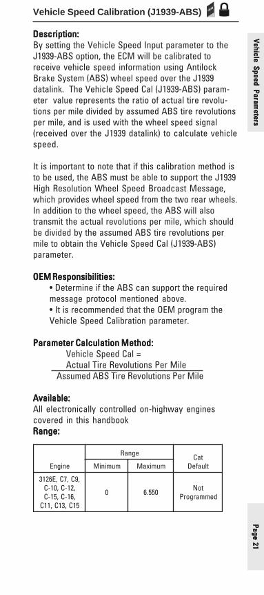
Description:Description:Description:Description:Description:By setting the Vehicle Speed Input parameter to theJ1939-ABS option, the ECM will be calibrated toreceive vehicle speed information using AntilockBrake System (ABS) wheel speed over the J1939datalink. The Vehicle Speed Cal (J1939-ABS) param-eter value represents the ratio of actual tire revolu-tions per mile divided by assumed ABS tire revolutionsper mile, and is used with the wheel speed signal(received over the J1939 datalink) to calculate vehiclespeed.
It is important to note that if this calibration method isto be used, the ABS must be able to support the J1939High Resolution Wheel Speed Broadcast Message,which provides wheel speed from the two rear wheels.In addition to the wheel speed, the ABS will alsotransmit the actual revolutions per mile, which shouldbe divided by the assumed ABS tire revolutions permile to obtain the Vehicle Speed Cal (J1939-ABS)parameter.
OEM Responsibilities:OEM Responsibilities:OEM Responsibilities:OEM Responsibilities:OEM Responsibilities:• Determine if the ABS can support the requiredmessage protocol mentioned above.• It is recommended that the OEM program theVehicle Speed Calibration parameter.
Parameter Calculation Method:Parameter Calculation Method:Parameter Calculation Method:Parameter Calculation Method:Parameter Calculation Method:Vehicle Speed Cal =Actual Tire Revolutions Per Mile
Assumed ABS Tire Revolutions Per Mile
Available:Available:Available:Available:Available:All electronically controlled on-highway enginescovered in this handbookRange:Range:Range:Range:Range:
enignE
egnaR taCtluafeDmuminiM mumixaM
,9C,7C,E6213,21-C,01-C,61-C,51-C51C,31C,11C
0 055.6 toNdemmargorP
Vehicle Speed Parameters
Vehicle Speed Parameters
Vehicle Speed Parameters
Vehicle Speed Parameters
Vehicle Speed Parameters

Page
22
Page
22
Page
22
Page
22
Page
22
Vehi
cle
Spee
d Pa
ram
eter
sVe
hicl
e Sp
eed
Para
met
ers
Vehi
cle
Spee
d Pa
ram
eter
sVe
hicl
e Sp
eed
Para
met
ers
Vehi
cle
Spee
d Pa
ram
eter
sVehicle Speed Limit (VSL)
Description:Description:Description:Description:Description:Vehicle speed limiting sets the maximum speed of thetruck. Vehicle Speed Limiting cuts off the fuel to theinjectors when the truck exceeds the programmedspeed. With the release of NOV95 Personality ModuleSoftware, VSL can be exceeded using cruise control ifthe High Cruise Control (HCC) Set Limit parameter isprogrammed higher than the Vehicle Speed Limitparameter (See page 32).
Available:Available:Available:Available:Available:All electronically controlled on-highway enginescovered in this handbook. The ability to program HCCSet Limit above VSL is available on heavy duty enginesonly.
Range:Range:Range:Range:Range:
Advantages:Advantages:Advantages:Advantages:Advantages:Using the VSL feature allows you to “gear fast - runslow” to optimize the balance between fuel economyand performance or simply specify for the best fueleconomy. Setting VSL allows the truck operator toconsistently operate the engine and truck at fuelefficient and safe vehicle speeds. Without VSL, mosttrucks can be capable of very high vehicle speeds,due to GFRS/GFRSS spec’ing methods.
Disadvantages:Disadvantages:Disadvantages:Disadvantages:Disadvantages:VSL can be a hard limit that allows no fuel until the
enignE
egnaR taCtluafeDmuminiM mumixaM
,7C,E6213MG9C
HPM03)h/mk84(
HPM57)h/mk121(
HPM57)h/mk121(
,7C,E6213rehtO9C
HPM03)h/mk84(
HPM721)h/mk402(
HPM721)h/mk402(
,21-C,01-C,61-C,51-C
,31C,11C51C
HPM03)h/mk84(
HPM721)h/mk402(
HPM721)h/mk402(

Page 23Page 23Page 23Page 23Page 23
vehicle slows to a speed below the programmed limit.This makes the common practice of “running at hills”very difficult. Soft VSL (See page 26) may alleviate thisproblem if the driver expects to operate at or aboveVSL on downhill runs.
Recommendations:Recommendations:Recommendations:Recommendations:Recommendations:✔ Gearing for best fuel economy.
✔ If engine RPM at Vehicle Speed Limit is less than orequal to Peak Toque RPM + 100, select anotheraxle ratio or transmission to increase engine RPM.Otherwise driveability may be adversely affected.Use Design Pro to check for gradeability at cruisespeed to ensure it is 1.0% or greater. Also, useDesign Pro to check for gradeability at peak torqueto ensure it is 1.8% (1.5% minimum).
enignE MPR HPM etoN
E62130002 06 sbl000,05<WCG
0022 06 sbl+000,05=WCG
01-C 0061 56htiwsnoitacilppaluaheniL
sselrosbl000,08
21-C
0551 56elgnisdeeps51ro,01,9
noissimsnartevirdrevo
-05410051
56lauddeeps81ro31
noissimsnartevirdrevo
51-C61-C
0551 56 wolebdnaph014
0051 56 evobadnaph534
7C
0002 06 sselroWCG000,05
0022 06roytilibatratseromsedivorP
ecnamrofrepdeepsdaol
9C 0561 56 sselroWCG000,06
11C 0541 56 sselroWCG000,06
31C 0541 56 sselroWCG000,08
51C0041 56 tf-bl0571nahtsseL
5231 56 evobadnatf-bl0571
Vehicle Speed Parameters
Vehicle Speed Parameters
Vehicle Speed Parameters
Vehicle Speed Parameters
Vehicle Speed Parameters

Page
24
Page
24
Page
24
Page
24
Page
24
Vehi
cle
Spee
d Pa
ram
eter
sVe
hicl
e Sp
eed
Para
met
ers
Vehi
cle
Spee
d Pa
ram
eter
sVe
hicl
e Sp
eed
Para
met
ers
Vehi
cle
Spee
d Pa
ram
eter
sVSL Protection
Description:Description:Description:Description:Description:This tamper -resistant feature is a programmed engineRPM limit that the engine will not exceed if the ECMshould lose the vehicle speed signal. In other words, ifthe vehicle speed signal is lost the truck will notexceed the Vehicle Speed Limit (VSL). The VSLProtection parameter should be set high enough thatthe vehicle can limp home, but low enough that it willnot be capable of exceeding the VSL.
Available:Available:Available:Available:Available:All electronically controlled on-highway enginescovered in this handbook
Range:Range:Range:Range:Range:
Advantages:Advantages:Advantages:Advantages:Advantages:The tamper resistance feature helps deter those whomay be tempted to try and circumvent the vehiclespeed signal. If the ECM were to lose the vehiclespeed signal for any reason, the engine rpm would belimited to the programmed RPM value of the VSLProtection parameter.
Disadvantages:Disadvantages:Disadvantages:Disadvantages:Disadvantages:None
Recommendations:Recommendations:Recommendations:Recommendations:Recommendations:✔ Caterpillar recommends electronic engines be
protected by setting this feature to an RPM valueequal to:
VSL Protection (rpm) = VSL x Rax Rt x M
_____________
60
where;VSL = Vehicle Speed LimitRa = Rear Axle RatioRt = Transmission Ratio in the highest gearM = Tire revolutions per mile
enignE
egnaR taCtluafeDmuminiM mumixaM
-C,21-C,01-C,11C,61-C,51
51C,31CMPR0001 MPRLET MPRLET
E6213MG MPR0071 MPR0071 MPR0071
rehtOE62139C,7C MPR0071 MPRLET MPRLET

Page 25Page 25Page 25Page 25Page 25
Tachometer Calibration
Description:Description:Description:Description:Description:Programmed by the OEM, this parameter is used by theECM to convert the engine speed signal into revolu-tions per minute for a tachometer.
Available:Available:Available:Available:Available:All electronically controlled on-highway enginescovered in this handbook
Range:Range:Range:Range:Range:
Advantages:Advantages:Advantages:Advantages:Advantages:By using the ECM Output to drive the in-dash tachom-eter the need for a separate sensor for the tachometeris eliminated.
Recommendations:Recommendations:Recommendations:Recommendations:Recommendations:✔ For most applications the factory default is correct.
✔ For ECM driven tachometer applications the in-dash tachometer must be set to the same pulsesper revolution (PPR) setting as the ECM.
✔ To verify that the ECM is driving the tachometer,perform the tachometer special test in Cat ET.When running the special test, the tachometerreading should sweep to approximately 1500 rpm. Ifnot, use the following calculation to correct theTachometer Calibration parameter value.
PPRPPRPPRPPRPPR = X X X X XTachTachTachTachTach 15001500150015001500
PPR =current Tachometer Calibrationvalue
Tach =value displayed on the tachometerduring the test
X =the desired Tachometer Calibrationvalue
1500 =value that should be displayed onthe tachometer during the test
enignE
egnaR taCtluafeDmuminiM mumixaM
,61-C,51-C,21-C,01-C51C,31C,11C RPP0.21 RPP0.005 RPP0.311
9C,7C,MGE6213045/035MG RPP0.2 RPP0.005 RPP5.71
9C,7C065TMG RPP0.2 RPP0.005 RPP0.2
rehtO6213 RPP0.2 RPP0.005 RPP0.431
Vehicle Speed Parameters
Vehicle Speed Parameters
Vehicle Speed Parameters
Vehicle Speed Parameters
Vehicle Speed Parameters
Page
26
Page
26
Page
26
Page
26
Page
26
Soft Vehicle Speed Limit
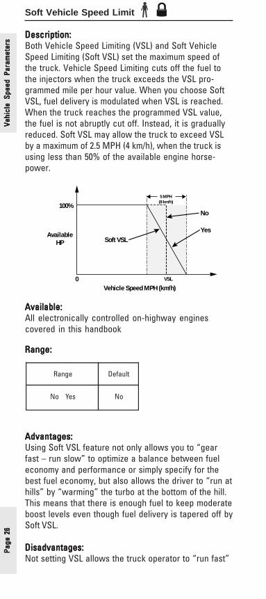
Description:Description:Description:Description:Description:Both Vehicle Speed Limiting (VSL) and Soft VehicleSpeed Limiting (Soft VSL) set the maximum speed ofthe truck. Vehicle Speed Limiting cuts off the fuel tothe injectors when the truck exceeds the VSL pro-grammed mile per hour value. When you choose SoftVSL, fuel delivery is modulated when VSL is reached.When the truck reaches the programmed VSL value,the fuel is not abruptly cut off. Instead, it is graduallyreduced. Soft VSL may allow the truck to exceed VSLby a maximum of 2.5 MPH (4 km/h), when the truck isusing less than 50% of the available engine horse-power.
100%
Vehicle Speed MPH (km/h)0
AvailableHP
VSL
5 MPH(8 km/h)
No
YesSoft VSL
Available:Available:Available:Available:Available:All electronically controlled on-highway enginescovered in this handbook
Range:Range:Range:Range:Range:
Advantages:Advantages:Advantages:Advantages:Advantages:Using Soft VSL feature not only allows you to “gearfast – run slow” to optimize a balance between fueleconomy and performance or simply specify for thebest fuel economy, but also allows the driver to “run athills” by “warming” the turbo at the bottom of the hill.This means that there is enough fuel to keep moderateboost levels even though fuel delivery is tapered off bySoft VSL.
Disadvantages:Disadvantages:Disadvantages:Disadvantages:Disadvantages:Not setting VSL allows the truck operator to “run fast”
Vehi
cle
Spee
d Pa
ram
eter
sVe
hicl
e Sp
eed
Para
met
ers
Vehi
cle
Spee
d Pa
ram
eter
sVe
hicl
e Sp
eed
Para
met
ers
Vehi
cle
Spee
d Pa
ram
eter
s
egnaR tluafeD
seYoN oN

Page 27Page 27Page 27Page 27Page 27
and as a result get poor fuel economy. Also, somedrivers may not like driving with Soft VSL enabled.Some common complaints are that there seems to belower power and the truck may not feel like it can holda constant speed. However, these effects are due tothe modulated fuel delivery, and once a driver getsused to them, will still result in the advantages listedpreviously. This perceived power loss can be evenmore noticeable on trucks that are spec’ed nearminimum gradeability requirements.
Recommendations:Recommendations:Recommendations:Recommendations:Recommendations:✔ Do not use Soft VSL unless you expect the truck to
operate at or above VSL in uneven or flat terrain.
Vehicle Speed Parameters
Vehicle Speed Parameters
Vehicle Speed Parameters
Vehicle Speed Parameters
Vehicle Speed Parameters

Page
28
Page
28
Page
28
Page
28
Page
28
Two-Speed Range Axle Ratio
Description:Description:Description:Description:Description:This parameter must be programmed when a Two-Speed Axle On/Off Switch is used by the ECM in orderto adjust the vehicle speed calibration. When a two-speed axle is used, the change in gear ratios from thehigh speed range to the low speed range alters thecalibration of the Vehicle Speed Limit and VehicleSpeed Calibration, which require a calibration adjust-ment to ensure the ECM-driven speedometer and ECM-stored information correctly reflect the actual vehiclespeed.
Available:Available:Available:Available:Available:All electronically controlled on-highway enginescovered in this handbook
Range:Range:Range:Range:Range:
Advantages:Advantages:Advantages:Advantages:Advantages:Proper calculation of the Low Speed Range Axle Ratioand High Speed Range Axle Ratio parameters isessential for proper cruise control and speedometer (ifcontrolled by the ECM) operation, and accurate fleetand driver trip data.
Disadvantages:Disadvantages:Disadvantages:Disadvantages:Disadvantages:None
Recommendations:Recommendations:Recommendations:Recommendations:Recommendations:✔ Let the OEM calculate the Low Speed Range Axle
Ratio and High Speed Range Axle Ratio parametersbased on the truck specifications.
✔ Recalculate and program the Low Speed RangeAxle Ratio and High Speed Range Axle Ratioparameters if any changes are made to the rearaxle ratios. Note that repairing or replacing theNote that repairing or replacing theNote that repairing or replacing theNote that repairing or replacing theNote that repairing or replacing therearend with the same axle ratio will not cause arearend with the same axle ratio will not cause arearend with the same axle ratio will not cause arearend with the same axle ratio will not cause arearend with the same axle ratio will not cause aproblem or require any recalculation for thisproblem or require any recalculation for thisproblem or require any recalculation for thisproblem or require any recalculation for thisproblem or require any recalculation for thisparameter.parameter.parameter.parameter.parameter.
enignE
egnaR
taCtluafeD
muminiM mumixaM
deepSwoLegnaR
deepShgiHegnaR
deepSwoLegnaR
deepShgiHegnaR
9C,7C,E6213 00.0 00.0 99.91 99.9 00.0
,51-C,21-C,01-C,31C,11C,61-C
51C00.1 00.1 99.91 99.9 00.1
Vehi
cle
Spee
d Pa
ram
eter
sVe
hicl
e Sp
eed
Para
met
ers
Vehi
cle
Spee
d Pa
ram
eter
sVe
hicl
e Sp
eed
Para
met
ers
Vehi
cle
Spee
d Pa
ram
eter
s

Page 29Page 29Page 29Page 29Page 29
Cruise Control Parameters
Factory Databook Optional
• Low Cruise ControlSpeed Set Limit ........................ ✔
• High Cruise ControlSpeed Set Limit ........................ ✔
• Engine Retarder ....................... ✔• Engine Retarder Delay ........... ✔• Engine Retarder Minimum
VSL Type .................................... ✔• Engine Retarder Minimum
Vehicle Speed .......................... ✔• Smart Idle Parameters ...........✔• Auto Retarder In Cruise .......... ✔• Auto Retarder In Cruise
Increment .................................. ✔• Cruise/Idle/PTO Switch
Configuration ...........................✔• Soft Cruise Control .................. ✔
Description:Description:Description:Description:Description:Cruise control allows the comfort and convenience ofautomotive type cruise control, complete with “bump”speed settings (“Bump Cruise” allows the operator tochange the vehicle speed in 1 MPH (1.6 km/h) incre-ments by “bumping” the Accel or Decel switch). Whilein cruise mode, the ECM monitors and maintainsvehicle speed at a set value. Additionally, the use ofan engine retarder while the cruise control is “On” hasthree programmable modes to match your brakingmethod. The retarder can also be programmed toautomatically turn on when the truck exceeds thecruise set speed while going down hill.
Advantages:Advantages:Advantages:Advantages:Advantages:Using cruise control can reduce driver fatigue andimprove fuel economy when used correctly.Caterpillar’s SoftCruise speed control can provide asmoother ride and additional fuel economy. TheSoftCruise feature is most beneficial in rolling terrain.
Disadvantages:Disadvantages:Disadvantages:Disadvantages:Disadvantages:Cruise control offers few disadvantages. If the LowCruise Control setting is set too low it may allow driversto operate the cruise in slower city traffic which may
Cruise Control Parameters
Cruise Control Parameters
Cruise Control Parameters
Cruise Control Parameters
Cruise Control Parameters

Page
30
Page
30
Page
30
Page
30
Page
30
Crui
se C
ontr
ol P
aram
eter
sCr
uise
Con
trol
Par
amet
ers
Crui
se C
ontr
ol P
aram
eter
sCr
uise
Con
trol
Par
amet
ers
Crui
se C
ontr
ol P
aram
eter
snot be desirable. However, if Low Cruise Control is settoo high the driver will not be able to use it whenclimbing long grades.
Using the standard cruise (by setting Caterpillar’sSoftCruise speed control to “off”) can cause the driverto sense uneven fueling - rapid fuel on/fuel off. Thismay discourage the use of cruise control and nega-tively effect fuel economy and driver comfort.
Recommendations:Recommendations:Recommendations:Recommendations:Recommendations:✔ Use cruise control by setting both the upper and
lower cruise control speed limits (HCC and LCC).
✔ Set the HCC at the highest speed you intend thevehicle to cruise. This may be above the VehicleSpeed Limit parameter setting.
✔ Do not set the cruise control limit right on top of ashift point. Driveability may be adversely affected.Check your settings against a split chart for yourdriveline.
RPM
MPH
Do not set CruiseControl Limits ontop of shift points
Incorrect Correct
✔ To take full advantage of SoftCruise, set the HighCruise (HCC) parameter to at least 3 mph below theVehicle Speed Limit Parameter (VSL).
Example: VSL = 65, HCC = 62 or less
✔ On the other hand, to encourage the use of cruisecontrol, set HCC to 3 mph above the recommendedVSL. This will result in the truck being operated incruise, with the HCC speed reached by “bumping”up the cruise.

Page 31Page 31Page 31Page 31Page 31
Low Cruise Control Set Speed Limit
Description:Description:Description:Description:Description:Low Cruise Control Set Speed Limit (LCC) sets theminimum vehicle speed for which cruise control maybe activated.
Available:Available:Available:Available:Available:All electronically controlled on-highway enginescovered in this handbook
Range:Range:Range:Range:Range:
Advantages:Advantages:Advantages:Advantages:Advantages:Programming of this parameter can restrict the use ofcruise control to those places where it is proper.
Disadvantages:Disadvantages:Disadvantages:Disadvantages:Disadvantages:If the Low Cruise Control Speed Set Limit is set too lowit may allow drivers to operate the cruise in slower citytraffic, which may not be desirable. However, if LCC isset too high, the driver will not be able to use it whenclimbing long grades.
Recommendations:Recommendations:Recommendations:Recommendations:Recommendations:✔ A typical value for Low Cruise Control Set Limit is 20
MPH (32 km/h).
enignE
egnaR taCtluafeDmuminiM mumixaM
MGE6213 HPM03)h/mk84(
HPM57)h/mk121(
HPM03)h/mk84(
rehtOE6213 HPM51)h/mk42(
HPM721)h/mk402(
HPM721)h/mk402(
MG9C,7C HPM52)h/mk04(
HPM57)h/mk121(
HPM52)h/mk04(
9C,7CrehtO
HPM51)h/mk42(
HPM721)h/mk402(
HPM721)h/mk402(
,21-C,01-C,61-C,51-C
,31C,11C51C
HPM51)h/mk42(
HPM721)h/mk402(
HPM721)h/mk402(
Cruise Control Parameters
Cruise Control Parameters
Cruise Control Parameters
Cruise Control Parameters
Cruise Control Parameters

Page
32
Page
32
Page
32
Page
32
Page
32
Crui
se C
ontr
ol P
aram
eter
sCr
uise
Con
trol
Par
amet
ers
Crui
se C
ontr
ol P
aram
eter
sCr
uise
Con
trol
Par
amet
ers
Crui
se C
ontr
ol P
aram
eter
sHigh Cruise Control Speed Set Limit
Description:Description:Description:Description:Description:High Cruise Control Speed Set Limit sets the maximumvehicle speed for which cruise control may be used. Ifthe driver attempts to set a vehicle speed higher thanthe programmed value of High Cruise Control SpeedSet Limit, the programmed value will become the cruiseset speed.
It is possible to program High Cruise Control Speed Setabove the programmed Vehicle Speed Limit. However,the driver can only attain speeds higher than VSL byusing the ACCEL switch and “bumping” up the vehiclespeed.
Available:Available:Available:Available:Available:All electronically controlled on-highway enginescovered in this handbook
Range:Range:Range:Range:Range:
Advantages:Advantages:Advantages:Advantages:Advantages:Using cruise control can reduce driver fatigue andimprove fuel economy. Fleets may want to set HCCabove VSL to encourage use of cruise control.
Disadvantages (possible):Disadvantages (possible):Disadvantages (possible):Disadvantages (possible):Disadvantages (possible):If High Cruise Control Speed Set is programmed to avalue above the Vehicle Speed Limit (VSL) the truckmost likely will be driven at higher speeds, thereforereducing fuel economy.
Recommendations:Recommendations:Recommendations:Recommendations:Recommendations:✔ Set the High Cruise Control Speed Set Limit at the
highest speed you intend the vehicle to cruise.
✔ Set the High Cruise Control Speed Set Limit 3 to 5MPH (5 to 13 km/h) below the Vehicle Speed Limit(VSL). This allows the driver to “run at hills” inrolling terrain and allows some reserve speed forpassing.
✔ If increased security is needed, this parameter canbe “locked” using the Customer Parameter Lockout(See page 159).
enignE
egnaR taCtluafeDmuminiM mumixaM
,7C,E6213MG9C
HPM03)h/mk84(
HPM57)h/mk121(
HPM57)h/mk121(
,7C,E6213rehtO9C
HPM02)h/mk23(
HPM721)h/mk402(
HPM721)h/mk402(
,21-C,01-C,61-C,51-C
,31C,11C51C
HPM03)h/mk84(
HPM721)h/mk402(
HPM721)h/mk402(

Page 33Page 33Page 33Page 33Page 33
Engine Retarder
Description:Description:Description:Description:Description:When the driver is operating an engine retarder withthe cruise control switch “On” and steps on theservice brake, two customer selectable modes ofoperation are available, Coast and Latch. One addi-tional Manual mode is available, which does notrequire the cruise switch to be in the “On” positionand operates like a retarder on a mechanicallygoverned engine.
Coast Mode:Coast Mode:Coast Mode:Coast Mode:Coast Mode:
On
Applied
Off
ReleasedServiceBrake
EngineRetarder
Coast Mode engages the engine retarder when thedriver presses (applies) the service brake pedal. Whenthe pedal is released, the retarder disengages.
Latch Mode:Latch Mode:Latch Mode:Latch Mode:Latch Mode:
On
Applied
ReleasedServiceBrake
EngineRetarder
Latch Mode engages the retarder when the driverpresses (applies) the service brake. The driver canthen release the service brake and the retarder willremain engaged until another input, such as depress-ing the throttle or clutch, engine RPM drops below 800RPM, or the retarder is turned off, is supplied.
Manual ModeManual ModeManual ModeManual ModeManual Mode does not require the Cruise ControlSwitch to be in the “On” position. In Manual Mode theengine retarder will activate anytime the RetarderSwitch is “On”, engine RPM is above 800 RPM and theengine is not being fueled.
Available:Available:Available:Available:Available:All electronically controlled on-highway enginescovered in this handbook
Cruise Control Parameters
Cruise Control Parameters
Cruise Control Parameters
Cruise Control Parameters
Cruise Control Parameters

Page
34
Page
34
Page
34
Page
34
Page
34
Range:Range:Range:Range:Range:
Advantages:Advantages:Advantages:Advantages:Advantages:The Coast and Latch settings of the Engine RetarderMode can offer increased driver comfort and reducedriver fatigue.
Disadvantages:Disadvantages:Disadvantages:Disadvantages:Disadvantages:None
Recommendations:Recommendations:Recommendations:Recommendations:Recommendations:✔ This is a driver preference feature. Program to the
setting the driver prefers.
enignE egnaR tluafeD
,7C,E6213,01-C,9C,51-C,21-C,11C,61-C
51C,31C
tsaoChctaL
launaMlaunaM
Crui
se C
ontr
ol P
aram
eter
sCr
uise
Con
trol
Par
amet
ers
Crui
se C
ontr
ol P
aram
eter
sCr
uise
Con
trol
Par
amet
ers
Crui
se C
ontr
ol P
aram
eter
s

Page 35Page 35Page 35Page 35Page 35
Engine Retarder Delay
Description:Description:Description:Description:Description:The Engine Retarder Delay parameter provides aprogrammable delay to assist shifting of some Euro-pean transmissions. The delay occurs after the basicretarder conditions have been met.
Available:Available:Available:Available:Available:C-10, C-12, C-15, C-16, C11, C13, C15 heavy duty engines
Range:Range:Range:Range:Range:
Advantages:Advantages:Advantages:Advantages:Advantages:Allows the use of a wider range of transmissions.
Disadvantages:Disadvantages:Disadvantages:Disadvantages:Disadvantages:None
Recommendations:Recommendations:Recommendations:Recommendations:Recommendations:✔ Engine Retarder Delay should be programmed to
zero except when required by the transmission.
enignE
egnaR taCtluafeDmuminiM mumixaM
,21-C,01-C,61-C,51-C
,31C,11C51C
sdnoces0 sdnoces3 sdnoces0
Cruise Control Parameters
Cruise Control Parameters
Cruise Control Parameters
Cruise Control Parameters
Cruise Control Parameters

Page
36
Page
36
Page
36
Page
36
Page
36
Crui
se C
ontr
ol P
aram
eter
sCr
uise
Con
trol
Par
amet
ers
Crui
se C
ontr
ol P
aram
eter
sCr
uise
Con
trol
Par
amet
ers
Crui
se C
ontr
ol P
aram
eter
sEngine Retarder Minimum VSL Type
Description:Description:Description:Description:Description:Engine Retarder Minimum Vehicle Speed Limit Typedefines how the Engine Retarder Minimum VehicleSpeed parameter will be used.
If the Engine Retarder Minimum Vehicle Speed LimitType is programmed to the “soft” setting, the engineretarder will remain ON below the value programmed inthe Engine Retarder Minimum Vehicle Speed until thenormal engine retarder turn-off parameters are met.
If the Engine Retarder Minimum Vehicle Speed LimitType is programmed to the “hard” setting, the engineretarder will turn off when the value programmed in theEngine Retarder Minimum Vehicle Speed is reached.
In both cases the engine retarder will remain off untilvehicle speed is higher than the programmed value ofthe Engine Retarder Minimum Vehicle Speed and theretarder has been re-engaged.
Available:Available:Available:Available:Available:C-10, C-12, C-15, C-16, C11, C13, C15 heavy duty engines
Range:Range:Range:Range:Range:
Advantages:Advantages:Advantages:Advantages:Advantages:Provides flexibility for driver comfort while complyingto local restrictions.
Disadvantages:Disadvantages:Disadvantages:Disadvantages:Disadvantages:None
Recommendations:Recommendations:Recommendations:Recommendations:Recommendations:✔ This is a driver preference feature. Program to the
setting the driver prefers.
enignE egnaR tluafeDtaC
,21-C,01-C,61-C,51-C
,31C,11C51C
timiLtfoStimiLdraH timiLdraH
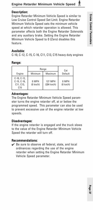
Page 37Page 37Page 37Page 37Page 37
Engine Retarder Minimum Vehicle Speed
Description:Description:Description:Description:Description:Engine Retarder Minimum Vehicle Speed is similar toLow Cruise Control Speed Set Limit. Engine RetarderMinimum Vehicle Speed sets the minimum vehiclespeed at which retarder operation is allowed. Thisparameter affects both the Engine Retarder Solenoidsand any auxiliary brake. Setting the Engine RetarderMinimum Vehicle Speed to 0 (Zero) disables thisfeature.
Available:Available:Available:Available:Available:C-10, C-12, C-15, C-16, C11, C13, C15 heavy duty engines
Range:Range:Range:Range:Range:
Advantages:Advantages:Advantages:Advantages:Advantages:The Engine Retarder Minimum Vehicle Speed param-eter turns the engine retarder off, at or below theprogrammed speed. This parameter can also be usedto prevent excessive use of the engine retarder at lowspeeds.
Disadvantages:Disadvantages:Disadvantages:Disadvantages:Disadvantages:If the engine retarder is engaged and the truck slowsto the value of the Engine Retarder Minimum VehicleSpeed the retarder will turn off.
Recommendations:Recommendations:Recommendations:Recommendations:Recommendations:✔ Be sure to observe all federal, state, and local
ordinances regarding the use of the engineretarder when setting the Engine Retarder MinimumVehicle Speed parameter.
enignE
egnaR taCtluafeDmuminiM mumixaM
,21-C,01-C,61-C,51-C
,31C,11C51C
HPM0)h/mk0(
HPM721)h/mk402(
HPM0)h/mk0(
Cruise Control Parameters
Cruise Control Parameters
Cruise Control Parameters
Cruise Control Parameters
Cruise Control Parameters
Page
38
Page
38
Page
38
Page
38
Page
38
Smart Idle Parameters
Description:Description:Description:Description:Description:This parameter is used to determine the voltage trippoint below which the Battery Monitor and EngineSpeed Control System will automatically elevateengine idle in order to maintain ideal battery systemvoltage. The engine idle will only be increased if thevehicle is stopped and the transmission is out of gear.If these conditions are not met, the engine idle will notbe adjusted.
The engine idle will be increased to 1000 RPM, or willbe increased by an amount less than 1000 RPM if theIdle RPM Limit parameter is programmed less than 1000RPM (see page 47).
Note:Note:Note:Note:Note:This feature requires the installation of a NeutralSwitch on J1/P1 terminal-62 (Input #12). Engine speedwill only be elevated when the transmission is inneutral.
Available:Available:Available:Available:Available:All electronically controlled on-highway enginescovered in this handbook
Range:Range:Range:Range:Range:
Advantages:Advantages:Advantages:Advantages:Advantages:Promotes additional battery life.
Disadvantages:Disadvantages:Disadvantages:Disadvantages:Disadvantages:Slight effect on fuel economy if the engine idle iselevated too often.
Recommendations:Recommendations:Recommendations:Recommendations:Recommendations:✔ Set to 12.2 V for a 12 V system, and 24.5 V for a 24 V
system.
egnaR taCtluafeDmuminiM mumixaM
stlov0 stlov5.52 stlov0
Crui
se C
ontr
ol P
aram
eter
sCr
uise
Con
trol
Par
amet
ers
Crui
se C
ontr
ol P
aram
eter
sCr
uise
Con
trol
Par
amet
ers
Crui
se C
ontr
ol P
aram
eter
s
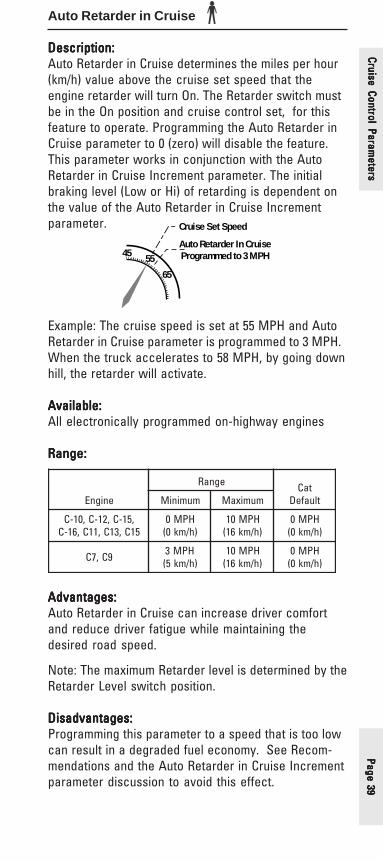
Page 39Page 39Page 39Page 39Page 39
Cruise Control Parameters
Cruise Control Parameters
Cruise Control Parameters
Cruise Control Parameters
Cruise Control Parameters
Auto Retarder in Cruise
Description:Description:Description:Description:Description:Auto Retarder in Cruise determines the miles per hour(km/h) value above the cruise set speed that theengine retarder will turn On. The Retarder switch mustbe in the On position and cruise control set, for thisfeature to operate. Programming the Auto Retarder inCruise parameter to 0 (zero) will disable the feature.This parameter works in conjunction with the AutoRetarder in Cruise Increment parameter. The initialbraking level (Low or Hi) of retarding is dependent onthe value of the Auto Retarder in Cruise Incrementparameter.
45 55
65
Auto Retarder In CruiseProgrammed to 3 MPH
Cruise Set Speed
Example: The cruise speed is set at 55 MPH and AutoRetarder in Cruise parameter is programmed to 3 MPH.When the truck accelerates to 58 MPH, by going downhill, the retarder will activate.
Available:Available:Available:Available:Available:All electronically programmed on-highway engines
Range:Range:Range:Range:Range:
Advantages:Advantages:Advantages:Advantages:Advantages:Auto Retarder in Cruise can increase driver comfortand reduce driver fatigue while maintaining thedesired road speed.
Note: The maximum Retarder level is determined by theRetarder Level switch position.
Disadvantages:Disadvantages:Disadvantages:Disadvantages:Disadvantages:Programming this parameter to a speed that is too lowcan result in a degraded fuel economy. See Recom-mendations and the Auto Retarder in Cruise Incrementparameter discussion to avoid this effect.
enignE
egnaR taCtluafeDmuminiM mumixaM
,51-C,21-C,01-C51C,31C,11C,61-C
HPM0)h/mk0(
HPM01)h/mk61(
HPM0)h/mk0(
9C,7C HPM3)h/mk5(
HPM01)h/mk61(
HPM0)h/mk0(

Page
40
Page
40
Page
40
Page
40
Page
40
Crui
se C
ontr
ol P
aram
eter
sCr
uise
Con
trol
Par
amet
ers
Crui
se C
ontr
ol P
aram
eter
sCr
uise
Con
trol
Par
amet
ers
Crui
se C
ontr
ol P
aram
eter
sRecommendations:Recommendations:Recommendations:Recommendations:Recommendations:✔ If Auto Retarder in Cruise is desired, program the
parameter to 3 – 5 MPH (5 – 8 km/h) to take advan-tage of SoftCruise. The minimum setting with SoftCruise is 3 MPH due to the fact that Soft Cruiserequires 2.5 MPH to work correctly.

Page 41Page 41Page 41Page 41Page 41
Auto Retarder in Cruise Increment
Description:Description:Description:Description:Description:The Auto Retarder in Cruise Increment parameterworks in conjunction with the Auto Retarder in Cruiseparameter and controls the retarder level. It requiresthat Auto Retarder in Cruise parameter to be pro-grammed to a value other than 0 (Zero).
45 55
65
Auto Retarder In Cruise Programmed to 3 MPH
Auto Retarder In Cruise IncrementProgrammed to 2 MPH
Low 58 MPHMedium 60 MPH
High 62 MPH
Cruise Set Speed
Example: The cruise speed is set to 55 MPH and AutoRetarder in Cruise parameter is programmed to 3 MPHand Auto Retarder in Cruise Increment is programmedto 2 MPH. When the truck accelerates to 58 MPH, bygoing down hill, the Low retarder level will activate. Ifthe truck continues to accelerate, Medium levelretarding would activate at 60 MPH. High level ofretarding will activate if the truck reaches 62 MPH.
Available:Available:Available:Available:Available:All electronically controlled on-highway enginescovered in this handbook
Range:Range:Range:Range:Range:
Advantages:Advantages:Advantages:Advantages:Advantages:Auto Retarder in Cruise Increment allows the driver tocustomize the Auto Retarder in Cruise feature to matchhis/her driving style.
The Auto Retarder in Cruise feature provides driverswho are “graded” for incentive purposes, an auto-matic method to control the amount of time above VSL.
Disadvantages:Disadvantages:Disadvantages:Disadvantages:Disadvantages:Programming the Auto Retarder in Cruise Incrementparameter too tightly can result in a degraded fueleconomy. For instance, if it is set to zero, and the AutoRetarder in Cruise parameter is set to 1 MPH, then allsix cylinders will retard when the vehicle exceedscruising speed by just 1 MPH. This can result in lessdesirable fuel economy.
enignE
egnaR taCtluafeDmuminiM mumixaM
,51-C,21-C,01-C,31C,11C,61-C
51C
HPM0)h/mk0(
HPM5)h/mk8(
HPM2)h/mk3(
Cruise Control Parameters
Cruise Control Parameters
Cruise Control Parameters
Cruise Control Parameters
Cruise Control Parameters

Page
42
Page
42
Page
42
Page
42
Page
42
Recommendations:Recommendations:Recommendations:Recommendations:Recommendations:✔ Program the Auto Retarder in Cruise Increment to 2
MPH. This will allow for all three levels of braking tobe used for smoother decel on moderate grades
✔ If High level of retarding is required, program theAuto Retarder in Cruise Increment to 0 (Zero). Ifthis is done, Soft Cruise should not be used (seepage 44 for details on Soft Cruise), since it requires2.5 MPH to work properly.
✔ Set the Auto Retarder in Cruise Increment param-eter to the preference of the driver, bearing in mindthe potentially negative affect on fuel economy ifthe increment is set too tightly.
Crui
se C
ontr
ol P
aram
eter
sCr
uise
Con
trol
Par
amet
ers
Crui
se C
ontr
ol P
aram
eter
sCr
uise
Con
trol
Par
amet
ers
Crui
se C
ontr
ol P
aram
eter
s

Page 43Page 43Page 43Page 43Page 43
Cruise Control Parameters
Cruise Control Parameters
Cruise Control Parameters
Cruise Control Parameters
Cruise Control Parameters
Cruise/Idle/PTO Switch Configuration
Description:Description:Description:Description:Description:Generally there are two accepted combinations ofcruise control switches. The specific combination ofswitches is a driver convenience feature.
Available:Available:Available:Available:Available:All electronically controlled on-highway enginescovered in this handbook
Range:Range:Range:Range:Range:
Advantages:Advantages:Advantages:Advantages:Advantages:The switch setting can be changed to meet driverpreferences.
Disadvantages:Disadvantages:Disadvantages:Disadvantages:Disadvantages:None
Recommendations:Recommendations:Recommendations:Recommendations:Recommendations:✔ None, this feature should be changed based on
driver preference.
enignE egnaR tluafeD
9C,7C,E6213MG
,21-C,01-C,61-C,51-C
,31C,11C51C
-/emuseR-leccA/teS-leceD/teSleceD
leccA/emuseR
leceD/emuseR-leccA/teS
9C,7C,E6213rehtO
leccA/emuseR-leceD/teS
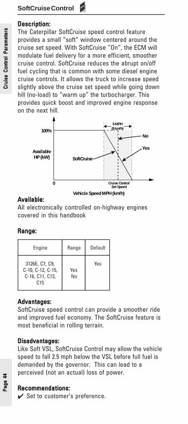
Page
44
Page
44
Page
44
Page
44
Page
44
Crui
se C
ontr
ol P
aram
eter
sCr
uise
Con
trol
Par
amet
ers
Crui
se C
ontr
ol P
aram
eter
sCr
uise
Con
trol
Par
amet
ers
Crui
se C
ontr
ol P
aram
eter
sSoftCruise Control
Description:Description:Description:Description:Description:The Caterpillar SoftCruise speed control featureprovides a small “soft” window centered around thecruise set speed. With SoftCruise “On”, the ECM willmodulate fuel delivery for a more efficient, smoothercruise control. SoftCruise reduces the abrupt on/offfuel cycling that is common with some diesel enginecruise controls. It allows the truck to increase speedslightly above the cruise set speed while going downhill (no-load) to “warm up” the turbocharger. Thisprovides quick boost and improved engine responseon the next hill.
100%
Vehicle Speed MPH (km/h)
0
AvailableHP (kW)
Cruise ControlSet Speed
5 MPH(8 km/h)
No
Yes
SoftCruise
Available:Available:Available:Available:Available:All electronically controlled on-highway enginescovered in this handbook
Range:Range:Range:Range:Range:
Advantages:Advantages:Advantages:Advantages:Advantages:SoftCruise speed control can provide a smoother rideand improved fuel economy. The SoftCruise feature ismost beneficial in rolling terrain.
Disadvantages:Disadvantages:Disadvantages:Disadvantages:Disadvantages:Like Soft VSL, SoftCruise Control may allow the vehiclespeed to fall 2.5 mph below the VSL before full fuel isdemanded by the governor. This can lead to aperceived (not an actual) loss of power.
Recommendations:Recommendations:Recommendations:Recommendations:Recommendations:✔ Set to customer’s preference.
enignE egnaR tluafeD
,9C,7C,E6213,51-C,21-C,01-C
,31C,11C,61-C51C
seYoN
seY

Page 45Page 45Page 45Page 45Page 45
Idle ParametersFORMERLY - OLD PTO
PTO GOVERNOR PARAMETERS
Factory Databook Optional
• Idle Vehicle Speed Limit ........ ✔• Idle RPM Limit ........................... ✔• Idle/PTO RPM Ramp Rate ......✔• Idle/PTO Bump RPM ...............✔• Fast Idle RPM #1 & #2 ............. ✔• Warm Up Mode Idle Speed ... ✔
Idle Parameters
Idle Parameters
Idle Parameters
Idle Parameters
Idle Parameters

Page
46
Page
46
Page
46
Page
46
Page
46
Idle
Par
amet
ers
Idle
Par
amet
ers
Idle
Par
amet
ers
Idle
Par
amet
ers
Idle
Par
amet
ers
Idle Vehicle Speed LimitFORMERLY - IDLE/PTO VEHICLE SPEED LIMIT OR
PTO/EXTENDED IDLE VEHICLE SPEED LIMIT OR
PTO MODE VEHICLE SPEED LIMIT
Description:Description:Description:Description:Description:Idle Vehicle Speed Limit is the maximum vehicle speedallowed when the engine is in the Idle Mode. (IdleMode is entered if the engine RPM is set by the cruisecontrol Set/Resume switch, when the cruise controlOn/Off switch is in the On position.) If the valueprogrammed in the Idle Vehicle Speed Limit parameteris exceeded, the set engine rpm will not be main-tained.
Available:Available:Available:Available:Available:All electronically controlled on-highway enginescovered in this handbook
Range:Range:Range:Range:Range:
Advantages:Advantages:Advantages:Advantages:Advantages:None
Disadvantages:Disadvantages:Disadvantages:Disadvantages:Disadvantages:None
Recommendations:Recommendations:Recommendations:Recommendations:Recommendations:✔ For non-PTO operations where overnight idling is
the primary usage of this feature, set the Idle/PTOVehicle Speed Limit to 2 MPH.
✔ For PTO Operation use the Dedicated PTO featureand related parameters (see page 52)
egnaR taCtluafeDmuminiM mumixaM
HPM1)h/mk2(
HPM51)h/mk42(
HPM1)h/mk2(
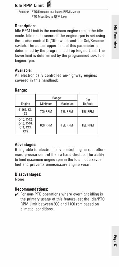
Page 47Page 47Page 47Page 47Page 47
Idle RPM LimitFORMERLY - PTO/EXTENDED IDLE ENGINE RPM LIMIT OR
PTO MODE ENGINE RPM LIMIT
Description:Description:Description:Description:Description:Idle RPM Limit is the maximum engine rpm in the idlemode. Idle mode occurs if the engine rpm is set usingthe cruise control On/Off switch and the Set/Resumeswitch. The actual upper limit of this parameter isdetermined by the programmed Top Engine Limit. Thelower limit is determined by the programmed Low IdleEngine rpm.
Available:Available:Available:Available:Available:All electronically controlled on-highway enginescovered in this handbook
Range:Range:Range:Range:Range:
Advantages:Advantages:Advantages:Advantages:Advantages:Being able to electronically control engine rpm offersmore precise control than a hand throttle. The abilityto limit maximum engine rpm in the Idle mode savesfuel and prevents unnecessary engine wear.
Disadvantages:Disadvantages:Disadvantages:Disadvantages:Disadvantages:None
Recommendations:Recommendations:Recommendations:Recommendations:Recommendations:✔ For non-PTO operations where overnight idling is
the primary usage of this feature, set the Idle/PTORPM Limit between 900 and 1100 rpm based onclimatic conditions.
Idle Parameters
Idle Parameters
Idle Parameters
Idle Parameters
Idle Parameters
enignE
egnaR taCtluafeDmuminiM mumixaM
,7C,E62139C MPR007 MPRLET MPRLET
,21-C,01-C,61-C,51-C
,31C,11C51C
MPR006 MPRLET MPRLET
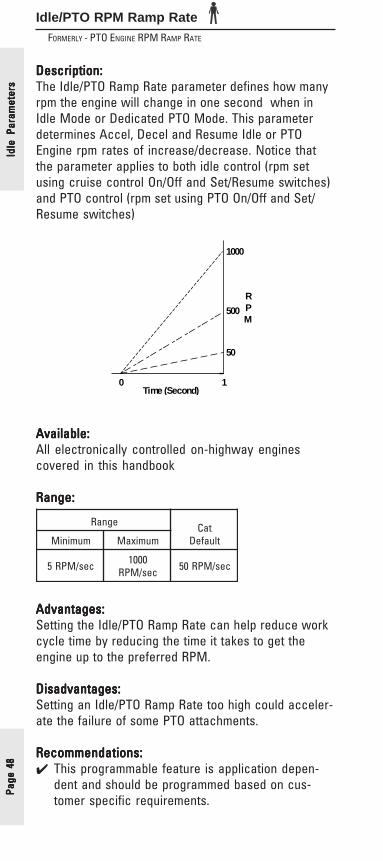
Page
48
Page
48
Page
48
Page
48
Page
48
Idle/PTO RPM Ramp RateFORMERLY - PTO ENGINE RPM RAMP RATE
Description:Description:Description:Description:Description:The Idle/PTO Ramp Rate parameter defines how manyrpm the engine will change in one second when inIdle Mode or Dedicated PTO Mode. This parameterdetermines Accel, Decel and Resume Idle or PTOEngine rpm rates of increase/decrease. Notice thatthe parameter applies to both idle control (rpm setusing cruise control On/Off and Set/Resume switches)and PTO control (rpm set using PTO On/Off and Set/Resume switches)
0 1Time (Second)
50
500
1000
RPM
Available:Available:Available:Available:Available:All electronically controlled on-highway enginescovered in this handbook
Range:Range:Range:Range:Range:
Advantages:Advantages:Advantages:Advantages:Advantages:Setting the Idle/PTO Ramp Rate can help reduce workcycle time by reducing the time it takes to get theengine up to the preferred RPM.
Disadvantages:Disadvantages:Disadvantages:Disadvantages:Disadvantages:Setting an Idle/PTO Ramp Rate too high could acceler-ate the failure of some PTO attachments.
Recommendations:Recommendations:Recommendations:Recommendations:Recommendations:✔ This programmable feature is application depen-
dent and should be programmed based on cus-tomer specific requirements.
Idle
Par
amet
ers
Idle
Par
amet
ers
Idle
Par
amet
ers
Idle
Par
amet
ers
Idle
Par
amet
ers
egnaR taCtluafeDmuminiM mumixaM
ces/MPR5 0001ces/MPR ces/MPR05

Page 49Page 49Page 49Page 49Page 49
Idle/PTO Bump RPM
Description:Description:Description:Description:Description:The Idle/PTO RPM Bump determines the rpm incre-ment/decrement when the Accel/Decel switches arebriefly “bumped”. It applies to both Dedicated PTOand Idle modes of operation.
Available:Available:Available:Available:Available:All electronically controlled engines covered in thishandbook
Range:Range:Range:Range:Range:
Advantages:Advantages:Advantages:Advantages:Advantages:Setting the Idle/PTO RPM Bump can help reduce workcycle time by reducing the time it takes to get theengine up to the preferred RPM.
Disadvantages:Disadvantages:Disadvantages:Disadvantages:Disadvantages:None
Recommendations:Recommendations:Recommendations:Recommendations:Recommendations:✔ This programmable feature is application depen-
dent and should be programmed based on cus-tomer specific requirements.
Idle Parameters
Idle Parameters
Idle Parameters
Idle Parameters
Idle Parameters
egnaR taCtluafeDmuminiM mumixaM
MPR5 MPR005 MPR02
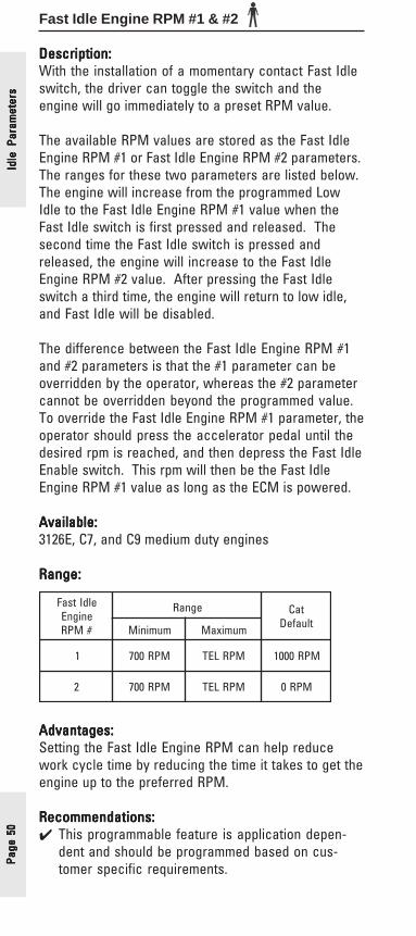
Page
50
Page
50
Page
50
Page
50
Page
50
Idle
Par
amet
ers
Idle
Par
amet
ers
Idle
Par
amet
ers
Idle
Par
amet
ers
Idle
Par
amet
ers
Fast Idle Engine RPM #1 & #2
Description:Description:Description:Description:Description:With the installation of a momentary contact Fast Idleswitch, the driver can toggle the switch and theengine will go immediately to a preset RPM value.
The available RPM values are stored as the Fast IdleEngine RPM #1 or Fast Idle Engine RPM #2 parameters.The ranges for these two parameters are listed below.The engine will increase from the programmed LowIdle to the Fast Idle Engine RPM #1 value when theFast Idle switch is first pressed and released. Thesecond time the Fast Idle switch is pressed andreleased, the engine will increase to the Fast IdleEngine RPM #2 value. After pressing the Fast Idleswitch a third time, the engine will return to low idle,and Fast Idle will be disabled.
The difference between the Fast Idle Engine RPM #1and #2 parameters is that the #1 parameter can beoverridden by the operator, whereas the #2 parametercannot be overridden beyond the programmed value.To override the Fast Idle Engine RPM #1 parameter, theoperator should press the accelerator pedal until thedesired rpm is reached, and then depress the Fast IdleEnable switch. This rpm will then be the Fast IdleEngine RPM #1 value as long as the ECM is powered.
Available:Available:Available:Available:Available:3126E, C7, and C9 medium duty engines
Range:Range:Range:Range:Range:
Advantages:Advantages:Advantages:Advantages:Advantages:Setting the Fast Idle Engine RPM can help reducework cycle time by reducing the time it takes to get theengine up to the preferred RPM.
Recommendations:Recommendations:Recommendations:Recommendations:Recommendations:✔ This programmable feature is application depen-
dent and should be programmed based on cus-tomer specific requirements.
eldItsaFenignE#MPR
egnaR taCtluafeDmuminiM mumixaM
1 MPR007 MPRLET MPR0001
2 MPR007 MPRLET MPR0

Page 51Page 51Page 51Page 51Page 51
Warm Up Mode Idle Speed
Description:Description:Description:Description:Description:The Warm Up Mode Idle Speed parameter determinesengine speed while the engine is in the warm up mode.The Warm Up Mode Idle Speed parameter will beactivated when the sum of coolant temperature andintake manifold air temperature is less than 86 o F(30 o C).
While the engine is in the warm up mode, the enginewill return to low idle if either the service brake or theclutch pedal is depressed, an automatic transmissionis put in gear, or the ECM detects vehicle speed. Afterreturning to low idle, the engine can then return toWarm Up Mode Idle Speed if the sum of coolanttemperature and intake manifold temperature 86 o F(30 o C) as mentioned above.
Note:Note:Note:Note:Note:Heavy duty warm up speed is non-programmable andis fixed at 1000 rpm.
Available:Available:Available:Available:Available:Medium duty on-highway engines
Range:Range:Range:Range:Range:
Advantages:Advantages:Advantages:Advantages:Advantages:This parameter allows the driver a flexible rpm rangefor the Warm Up Mode Idle Speed depending upon thespecific application.
Disadvantages:Disadvantages:Disadvantages:Disadvantages:Disadvantages:None
enignE
egnaR taCtluafeDmuminiM mumixaM
9C,7C,E6213 mpr007 mpr0041 mpr0001
Idle Parameters
Idle Parameters
Idle Parameters
Idle Parameters
Idle Parameters
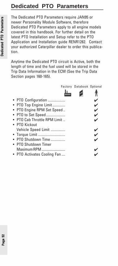
Page
52
Page
52
Page
52
Page
52
Page
52
Ded
icat
ed P
TO P
aram
eter
sD
edic
ated
PTO
Par
amet
ers
Ded
icat
ed P
TO P
aram
eter
sD
edic
ated
PTO
Par
amet
ers
Ded
icat
ed P
TO P
aram
eter
s
Dedicated PTO Parameters
The Dedicated PTO Parameters require JAN95 ornewer Personality Module Software, thereforeDedicated PTO Parameters apply to all engine modelscovered in this handbook. For further detail on thelatest PTO Installation and Setup refer to the PTOApplication and Installation guide RENR1282. Contactyour authorized Caterpillar dealer to order this publica-tion.
Anytime the Dedicated PTO circuit is Active, both thelength of time and the fuel used will be stored in theTrip Data Information in the ECM (See the Trip DataSection pages 160-165).
Factory Databook Optional
• PTO Configuration ................... ✔• PTO Top Engine Limit .............. ✔• PTO Engine RPM Set Speed .. ✔• PTO to Set Speed..................... ✔• PTO Cab Throttle RPM Limit .. ✔• PTO Kickout
Vehicle Speed Limit ................ ✔• Torque Limit .............................. ✔• PTO Shutdown Time ................ ✔• PTO Shutdown Timer
Maximum RPM .......................... ✔• PTO Activates Cooling Fan .... ✔
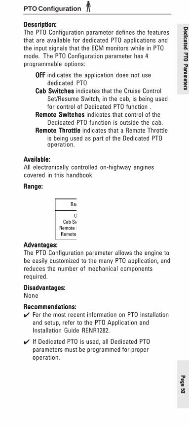
Page 53Page 53Page 53Page 53Page 53
PTO Configuration
Description:Description:Description:Description:Description:The PTO Configuration parameter defines the featuresthat are available for dedicated PTO applications andthe input signals that the ECM monitors while in PTOmode. The PTO Configuration parameter has 4programmable options:
OFFOFFOFFOFFOFF indicates the application does not usededicated PTO
Cab SwitchesCab SwitchesCab SwitchesCab SwitchesCab Switches indicates that the Cruise ControlSet/Resume Switch, in the cab, is being usedfor control of Dedicated PTO function .
Remote SwitchesRemote SwitchesRemote SwitchesRemote SwitchesRemote Switches indicates that control of theDedicated PTO function is outside the cab.
Remote ThrottleRemote ThrottleRemote ThrottleRemote ThrottleRemote Throttle indicates that a Remote Throttleis being used as part of the Dedicated PTOoperation.
Available:Available:Available:Available:Available:All electronically controlled on-highway enginescovered in this handbook
Range:Range:Range:Range:Range:
Ran
OCab Sw
Remote SRemote
Advantages:Advantages:Advantages:Advantages:Advantages:The PTO Configuration parameter allows the engine tobe easily customized to the many PTO application, andreduces the number of mechanical componentsrequired.
Disadvantages:Disadvantages:Disadvantages:Disadvantages:Disadvantages:None
Recommendations:Recommendations:Recommendations:Recommendations:Recommendations:✔ For the most recent information on PTO installation
and setup, refer to the PTO Application andInstallation Guide RENR1282.
✔ If Dedicated PTO is used, all Dedicated PTOparameters must be programmed for properoperation.
Dedicated PTO
Parameters
Dedicated PTO
Parameters
Dedicated PTO
Parameters
Dedicated PTO
Parameters
Dedicated PTO
Parameters

Page
54
Page
54
Page
54
Page
54
Page
54
Ded
icat
ed P
TO P
aram
eter
sD
edic
ated
PTO
Par
amet
ers
Ded
icat
ed P
TO P
aram
eter
sD
edic
ated
PTO
Par
amet
ers
Ded
icat
ed P
TO P
aram
eter
sPTO Top Engine Limit
Description:Description:Description:Description:Description:If the engine has been wired to work in the dedicatedPTO mode, the PTO Top Engine Limit parameter can beprogrammed to a value up to the maximum rpm of theengine. This parameter is only in effect when theengine is in the Dedicated PTO mode. The valueprogrammed can exceed the programmed Top EngineLimit RPM (see page 69).
Available:Available:Available:Available:Available:All electronically controlled on-highway enginescovered in this handbook
Range:Range:Range:Range:Range:
Advantages:Advantages:Advantages:Advantages:Advantages:PTO Top Engine Limit allows the flexibility to work inPTO applications where additional RPM above theengine Top Engine Limit RPM is required, or whereRPM must be limited to prevent damage to the PTOdevice.
Disadvantages:Disadvantages:Disadvantages:Disadvantages:Disadvantages:None
Recommendations:Recommendations:Recommendations:Recommendations:Recommendations:✔ Refer to RENR1282 for specific details.
enignE
egnaR taCtluafeDmuminiM mumixaM
,21-C,01-C,61-C,51-C
,31C,11C51C
MPR006 MPRLET MPRLET
,7C,E6213MP9C
dna30RAMreilraE
MPR007 MPRLET MPRLET
MP9C,7Cdna40RAM
retaL
eldIwoLMPR MPRLET MPRLET

Page 55Page 55Page 55Page 55Page 55
PTO Engine RPM Set Speed
Description:Description:Description:Description:Description:PTO Engine RPM Set Speed is the engine RPM theengine will proceed to when the PTO On/Off circuit isOn and the Cruise/PTO Set switch is toggled. If thePTO to Set Speed parameter (see page 56) is pro-grammed to Yes, the engine will go to the PTO EngineRPM Set Speed whenever the PTO On/Off circuit is On.PTO Configuration must be programmed to CabSwitches or Remote Switches before this parametercan be programmed.
Available:Available:Available:Available:Available:All electronically controlled on-highway enginescovered in this handbook
Range:Range:Range:Range:Range:
Advantages:Advantages:Advantages:Advantages:Advantages:Allows the flexibility to go to a specific engine rpmevery time when in Dedicated PTO operation.
Disadvantages:Disadvantages:Disadvantages:Disadvantages:Disadvantages:None
Recommendations:Recommendations:Recommendations:Recommendations:Recommendations:✔ Refer to RENR1282 for further details.
egnaR taCtluafeDmuminiM mumixaM
eldIwoLMPR LETOTP MPR0
Dedicated PTO
Parameters
Dedicated PTO
Parameters
Dedicated PTO
Parameters
Dedicated PTO
Parameters
Dedicated PTO
Parameters

Page
56
Page
56
Page
56
Page
56
Page
56
Ded
icat
ed P
TO P
aram
eter
sD
edic
ated
PTO
Par
amet
ers
Ded
icat
ed P
TO P
aram
eter
sD
edic
ated
PTO
Par
amet
ers
Ded
icat
ed P
TO P
aram
eter
sPTO to Set Speed
Description:Description:Description:Description:Description:When the PTO to Set Speed parameter is programmedto Yes, the engine rpm will go directly to the valueprogrammed in the PTO Engine RPM Set Speedparameter (see page 55) when Dedicated PTO is On .PTO Configuration must be programmed to CabSwitches or Remote Switches before this parametercan be programmed.
Available:Available:Available:Available:Available:All electronically controlled on-highway enginescovered in this handbook
Range:Range:Range:Range:Range:
Advantages:Advantages:Advantages:Advantages:Advantages:By automatically going to a programmed engine RPMevery time Dedicated PTO is engaged, cycle time canbe reduced and precise control of engine rpm ispossible for specialized PTO applications.
Disadvantages:Disadvantages:Disadvantages:Disadvantages:Disadvantages:None
Recommendations:Recommendations:Recommendations:Recommendations:Recommendations:✔ Set the PTO to Set Speed Parameter to YES if the
application requires the engine to go to a specifiedRPM every time the Dedicated PTO feature is On.
✔ For further details, refer to RENR1282.

Page 57Page 57Page 57Page 57Page 57
PTO Cab Throttle RPM Limit
(Also knows as “PTO Cab Controls RPM Limit”)
Description:Description:Description:Description:Description:The PTO Cab Throttle RPM Limit parameter determinesthe engine rpm limit of the Cab Throttle Position Sensorwhen the PTO Configuration parameter is programmedto Cab Switches and the engine is in the DedicatedPTO mode.
• If Programmed to Low IdleLow IdleLow IdleLow IdleLow Idle, the Cab ThrottlePosition Sensor is ignored.
• If programmed to TELTELTELTELTEL, the engine will operate tothe programmed Top Engine Limit rpm.
• If Programmed to PTO TELPTO TELPTO TELPTO TELPTO TEL, the engine will operateto the programmed PTO Top Engine Limit rpm.
If PTO Configuration is programmed to RemoteSwitches or Remote Throttle, the ECM will alwaysignore the Cab Throttle Position Sensor when theengine is in the Dedicated PTO mode.
Available:Available:Available:Available:Available:All electronically controlled on-highway enginescovered in this handbook
Range:Range:Range:Range:Range:
Range
Low IdleTEL
PTO TEL
Advantages:Advantages:Advantages:Advantages:Advantages:Prevents the use of the cab throttle to override PTOsettings and overspeeding the PTO device.
Disadvantages:Disadvantages:Disadvantages:Disadvantages:Disadvantages:None
Recommendations:Recommendations:Recommendations:Recommendations:Recommendations:✔Refer to RENR1282 for more specific details.
Dedicated PTO
Parameters
Dedicated PTO
Parameters
Dedicated PTO
Parameters
Dedicated PTO
Parameters
Dedicated PTO
Parameters

Page
58
Page
58
Page
58
Page
58
Page
58
Ded
icat
ed P
TO P
aram
eter
sD
edic
ated
PTO
Par
amet
ers
Ded
icat
ed P
TO P
aram
eter
sD
edic
ated
PTO
Par
amet
ers
Ded
icat
ed P
TO P
aram
eter
sPTO Kickout Vehicle Speed Limit
Description:Description:Description:Description:Description:Similar in operation to Vehicle Speed Limit, but it onlyapplies when the engine is in Dedicated PTO Mode.PTO mode is entered if the PTO On/Off circuit is On. Ifthe PTO Vehicle Speed limit is exceeded, the enginewill “kick out” of the Dedicated PTO mode and nolonger maintain the set engine rpm.
Available:Available:Available:Available:Available:All electronically controlled on-highway enginescovered in this handbook
*Note: For model year 2001 HD engines this parameterwas referred to as “PTO Vehicle Speed Limit”, thename was changed for HD engines afterwards.
Range:Range:Range:Range:Range:
Advantages:Advantages:Advantages:Advantages:Advantages:Some Dedicated PTO applications use transmissiondriven PTO’s. In some cases the vehicle is required totravel at speeds in excess of the 15 MPH limit. Thatwas not possible with the combined Idle/PTO VehicleSpeed Limit parameter. The customer now has theflexibility to limit vehicle speed in both Idle andDedicated PTO operation.
Disadvantages:Disadvantages:Disadvantages:Disadvantages:Disadvantages:None
Recommendations:Recommendations:Recommendations:Recommendations:Recommendations:✔ Refer to RENR1282 for more specific details
egnaR taCtluafeDmuminiM mumixaM
HPM1)h/mk2(
HPM721)h/mk402(
HPM1)h/mk2(

Page 59Page 59Page 59Page 59Page 59
Torque Limit
Description:Description:Description:Description:Description:The Torque Limit parameter defines the maximumtorque output of the engine during Dedicated PTOoperation. The maximum value is the Rated Torque ofthe engine. If the Torque Limit is Programmed to avalue higher than the rated torque of the engine, thetorque limit is ignored.
Torque
Engine Speed (RPM)
Engine Torque Curve
Programmed EngineTorque Limit
Available:Available:Available:Available:Available:All electronically controlled on-highway enginescovered in this handbook
Range:Range:Range:Range:Range:
* Actual Maximum is based on engine rating
Advantages:Advantages:Advantages:Advantages:Advantages:By programming a Torque Limit the ECM can helpprevent damage to engine driven PTO devices due toover-torque from the engine.
Disadvantages:Disadvantages:Disadvantages:Disadvantages:Disadvantages:None
Recommendations:Recommendations:Recommendations:Recommendations:Recommendations:✔ Refer to RENR1282 for additional information.
enignE
egnaR taCtluafeDmuminiM mumixaM
,21-C,01-C,61-C,51-C
,31C,11C51C
tfbl002)mN072(
*tfbl0052)mN9833(
tfbl0052)mN0043(
,7C,E62139C
tfbl001)mN531(
*tfbl0002)mN0072(
tfbl0002)mN0072(
Dedicated PTO
Parameters
Dedicated PTO
Parameters
Dedicated PTO
Parameters
Dedicated PTO
Parameters
Dedicated PTO
Parameters
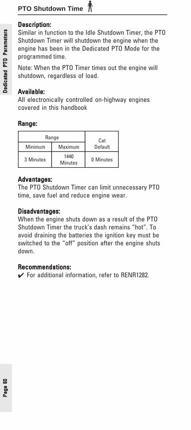
Page
60
Page
60
Page
60
Page
60
Page
60
PTO Shutdown Time
Description:Description:Description:Description:Description:Similar in function to the Idle Shutdown Timer, the PTOShutdown Timer will shutdown the engine when theengine has been in the Dedicated PTO Mode for theprogrammed time.
Note: When the PTO Timer times out the engine willshutdown, regardless of load.
Available:Available:Available:Available:Available:All electronically controlled on-highway enginescovered in this handbook
Range:Range:Range:Range:Range:
Advantages:Advantages:Advantages:Advantages:Advantages:The PTO Shutdown Timer can limit unnecessary PTOtime, save fuel and reduce engine wear.
Disadvantages:Disadvantages:Disadvantages:Disadvantages:Disadvantages:When the engine shuts down as a result of the PTOShutdown Timer the truck’s dash remains “hot”. Toavoid draining the batteries the ignition key must beswitched to the “off” position after the engine shutsdown.
Recommendations:Recommendations:Recommendations:Recommendations:Recommendations:✔ For additional information, refer to RENR1282.
egnaR taCtluafeDmuminiM mumixaM
setuniM3 0441setuniM setuniM0
Ded
icat
ed P
TO P
aram
eter
sD
edic
ated
PTO
Par
amet
ers
Ded
icat
ed P
TO P
aram
eter
sD
edic
ated
PTO
Par
amet
ers
Ded
icat
ed P
TO P
aram
eter
s

Page 61Page 61Page 61Page 61Page 61
PTO Shutdown Timer Maximum RPM
Description:Description:Description:Description:Description:PTO Shutdown Timer Maximum RPM can be used toreset the PTO Shutdown Timer. Programming thisparameter to 2120 rpm disables this feature and willnot allow the PTO Shutdown Timer to be overriddenby increasing engine rpm. If programmed to a valuebelow 2120 rpm, the timer will be reset wheneverengine RPM exceeds this programmed value.
Available:Available:Available:Available:Available:All heavy-duty on-highway engines covered in thishandbook
Range:Range:Range:Range:Range:
muminiM mumixaM tluafeD
mpr006 mpr0212 mpr0212
Dedicated PTO
Parameters
Dedicated PTO
Parameters
Dedicated PTO
Parameters
Dedicated PTO
Parameters
Dedicated PTO
Parameters
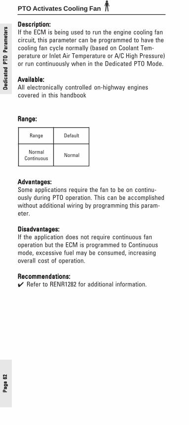
Page
62
Page
62
Page
62
Page
62
Page
62
PTO Activates Cooling Fan
Description:Description:Description:Description:Description:If the ECM is being used to run the engine cooling fancircuit, this parameter can be programmed to have thecooling fan cycle normally (based on Coolant Tem-perature or Inlet Air Temperature or A/C High Pressure)or run continuously when in the Dedicated PTO Mode.
Available:Available:Available:Available:Available:All electronically controlled on-highway enginescovered in this handbook
Range:Range:Range:Range:Range:
Advantages:Advantages:Advantages:Advantages:Advantages:Some applications require the fan to be on continu-ously during PTO operation. This can be accomplishedwithout additional wiring by programming this param-eter.
Disadvantages:Disadvantages:Disadvantages:Disadvantages:Disadvantages:If the application does not require continuous fanoperation but the ECM is programmed to Continuousmode, excessive fuel may be consumed, increasingoverall cost of operation.
Recommendations:Recommendations:Recommendations:Recommendations:Recommendations:✔ Refer to RENR1282 for additional information.
Ded
icat
ed P
TO P
aram
eter
sD
edic
ated
PTO
Par
amet
ers
Ded
icat
ed P
TO P
aram
eter
sD
edic
ated
PTO
Par
amet
ers
Ded
icat
ed P
TO P
aram
eter
s
egnaR tluafeD
lamroNsuounitnoC lamroN
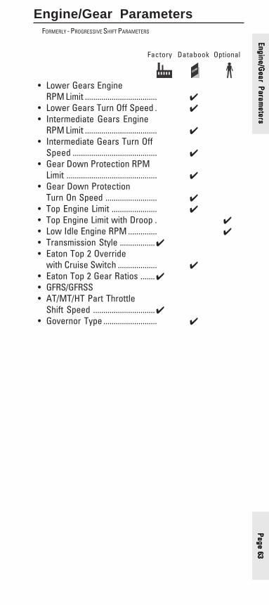
Page 63Page 63Page 63Page 63Page 63
Engine/Gear ParametersFORMERLY - PROGRESSIVE SHIFT PARAMETERS
Factory Databook Optional
• Lower Gears EngineRPM Limit ................................... ✔
• Lower Gears Turn Off Speed . ✔• Intermediate Gears Engine
RPM Limit ................................... ✔• Intermediate Gears Turn Off
Speed ......................................... ✔• Gear Down Protection RPM
Limit ............................................ ✔• Gear Down Protection
Turn On Speed ......................... ✔• Top Engine Limit ...................... ✔• Top Engine Limit with Droop . ✔• Low Idle Engine RPM .............. ✔• Transmission Style .................✔• Eaton Top 2 Override
with Cruise Switch ................... ✔• Eaton Top 2 Gear Ratios .......✔• GFRS/GFRSS• AT/MT/HT Part Throttle
Shift Speed ..............................✔• Governor Type .......................... ✔
Engine/Gear Param
etersEngine/G
ear Parameters
Engine/Gear Param
etersEngine/G
ear Parameters
Engine/Gear Param
eters
Page
64
Page
64
Page
64
Page
64
Page
64
Lower Gears Engine RPM LimitFORMERLY - LOW GEARS #1 ENGINE RPM LIMIT
Lower Gears Turn Off SpeedFORMERLY - LOW GEARS #1 TURN OFF SPEED
Intermediate Gears Engine RPM LimitFORMERLY - LOW GEARS #2 ENGINE RPM LIMIT
Intermediate Gears Turn Off SpeedFORMERLY - LOW GEARS #2 TURN OFF SPEED
Description:Description:Description:Description:Description:Lower Gears Engine RPM Limit and Intermediate GearsEngine RPM Limit are meant to approximate idealprogressive shifting. Lower Gear Engine RPM Limitingshould be used in conjunction with Intermediate GearsEngine RPM Limiting. However, you can choose to useonly Lower Gears Engine RPM Limit if that is bestsuited to your operation.
Both Lower and Intermediate Gears RPM Limiting have“soft” rpm limits. This means if you are in a heavilyloaded condition or starting on an especially steepgrade and do not want to shift until the enginereaches higher rpm, the limit will not stop you. If notheavily loaded, it simply slows the acceleration rate ofthe engine when you pass the programmed setting,prompting the driver to shift for the most “normal”operations.
The maximum engine acceleration rate above theLower Gears Engine RPM Limit is 33 rpm/sec and 25rpm/sec for Intermediate Gears Engine RPM Limiting.
The engine can accelerate all the way to yourprogrammed Top Engine limit (TEL) when necessaryand will not be noticed by most drivers if properlyprogrammed to fit your application.
Once the Lower Gears Engine RPM Limit has beendetermined, the Lower Gears Turn Off Speed isselected as the mean vehicle speed between wherethe Lower Gears Engine RPM Limit intersects the lineof gear to be limited and the line of the next highestgear. Next, Intermediate Gear Engine RPM Limit andIntermediate Gears Turn Off Speed are selected inmuch the same way. The values for all four parametersare automatically calculated when using Cat® DesignPro.
Available:Available:Available:Available:Available:All electronically controlled on-highway enginescovered in this handbook
Engi
ne/G
ear
Para
met
ers
Engi
ne/G
ear
Para
met
ers
Engi
ne/G
ear
Para
met
ers
Engi
ne/G
ear
Para
met
ers
Engi
ne/G
ear
Para
met
ers

Page 65Page 65Page 65Page 65Page 65
Range:Range:Range:Range:Range:Lower Gears Engine RPM Limit
Lower Gears Turn Off Speed
Intermediate Gears Engine RPM Limit
Intermediate Gears Turn Off Speed
Advantages:Advantages:Advantages:Advantages:Advantages:Lower Gears Engine RPM Limiting and IntermediateGears Engine RPM Limiting improve fuel economy bypromoting progressive shifting. Needlessly “windingup” the engine to higher rpms before up shiftingwastes both fuel and time while failing to take advan-tage of Caterpillar’s exceptional low rpm torque.
Disadvantages:Disadvantages:Disadvantages:Disadvantages:Disadvantages:This setting provides minimal fuel savings for long hauloperations unless the driver stops frequently andregularly tries to “wind it up”.
Engine/Gear Param
etersEngine/G
ear Parameters
Engine/Gear Param
etersEngine/G
ear Parameters
Engine/Gear Param
eters
enignE
egnaR taCtluafeDmuminiM mumixaM
-C,51-C,21-C,01-C51C,31C,11C,61
HPM3)h/mk5(
HPM03)h/mk84(
HPM3)h/mk5(
9C,7C,E6213 HPM1)h/mk2(
HPM51)h/mk42(
HPM1)h/mk2(
enignE
egnaR taCtluafeDmuminiM mumixaM
,61-C,51-C,21-C,01-C51C,31C,11C MPR0011 LET LET
9C,7C,E6213 MPR0051 LET LET
enignE
egnaR taCtluafeDmuminiM mumixaM
,61-C,51-C,21-C,01-C51C,31C,11C MPR0011 LET LET
0C,7C,E6213 MPR0051 LET LET
enignE
egnaR taCtluafeDmuminiM mumixaM
,51-C,21-C,01-C51C,31C,11C,61-C
HPM5)h/mk8(
HPM05)h/mk08(
HPM5)h/mk8(
9C,7C,E6213 HPM01)h/mk61(
HPM05)h/mk08(
HPM01)h/mk61(
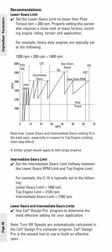
Page
66
Page
66
Page
66
Page
66
Page
66
Recommendations:Recommendations:Recommendations:Recommendations:Recommendations:Lower Gears LimitLower Gears LimitLower Gears LimitLower Gears LimitLower Gears Limit✔ Set the Lower Gears Limit no lower than Peak
Torque rpm + 200 rpm. Properly setting this param-eter requires a close look at many factors, includ-ing engine rating, terrain and application.
For example, heavy-duty engines are typically setat the following:
1200 rpm + 200 rpm = 1400 rpm
Note how Lower Gears and Intermediate Gears setting fit inthe total spec, especially in respect to Top Engine Limiting(stair step effect).
A similar graph would apply to mid-range engines.
Intermediate Gears LimitIntermediate Gears LimitIntermediate Gears LimitIntermediate Gears LimitIntermediate Gears Limit✔ Set the Intermediate Gears Limit halfway between
the Lower Gears RPM Limit and Top Engine Limit.
For example, the C-15 is typically set to the follow-ing:Lower Gears Limit = 1400 rpmTop Engine Limit = 2120 rpmIntermediate Gears Limit = 1760 rpm
Lower Gears and Intermediate Gears LimitsLower Gears and Intermediate Gears LimitsLower Gears and Intermediate Gears LimitsLower Gears and Intermediate Gears LimitsLower Gears and Intermediate Gears Limits✔ Use Cat® Design Pro program to determine the
most effective setting for your application.
Note: Turn Off Speeds are automatically calculated inthe Cat® Design Pro computer program. Cat® DesignPro is the easiest tool to use to build an effectivespec.
Engi
ne/G
ear
Para
met
ers
Engi
ne/G
ear
Para
met
ers
Engi
ne/G
ear
Para
met
ers
Engi
ne/G
ear
Para
met
ers
Engi
ne/G
ear
Para
met
ers
0 10 20 30 40 50 60 70
1000
1200
1400
1600
1800
2000
PeakTorque
VSL
HCC
Gear Down RPM
TEL
LCC
IntermediateGears
LowerGears
PTOVSL
MPH
RP
M
Gear DownSpeed
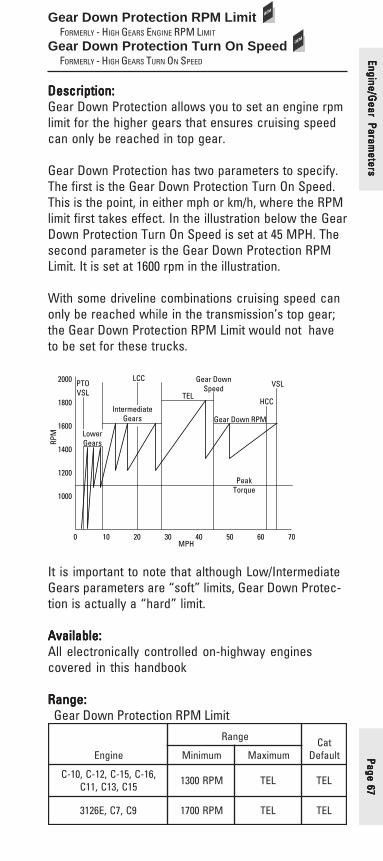
Page 67Page 67Page 67Page 67Page 67
Gear Down Protection RPM LimitFORMERLY - HIGH GEARS ENGINE RPM LIMIT
Gear Down Protection Turn On SpeedFORMERLY - HIGH GEARS TURN ON SPEED
Description:Description:Description:Description:Description:Gear Down Protection allows you to set an engine rpmlimit for the higher gears that ensures cruising speedcan only be reached in top gear.
Gear Down Protection has two parameters to specify.The first is the Gear Down Protection Turn On Speed.This is the point, in either mph or km/h, where the RPMlimit first takes effect. In the illustration below the GearDown Protection Turn On Speed is set at 45 MPH. Thesecond parameter is the Gear Down Protection RPMLimit. It is set at 1600 rpm in the illustration.
With some driveline combinations cruising speed canonly be reached while in the transmission’s top gear;the Gear Down Protection RPM Limit would not haveto be set for these trucks.
0 10 20 30 40 50 60 70
1000
1200
1400
1600
1800
2000
PeakTorque
VSL
HCC
Gear Down RPM
TEL
LCC
IntermediateGears
LowerGears
PTOVSL
MPH
RPM
Gear DownSpeed
It is important to note that although Low/IntermediateGears parameters are “soft” limits, Gear Down Protec-tion is actually a “hard” limit.
Available:Available:Available:Available:Available:All electronically controlled on-highway enginescovered in this handbook
Range:Range:Range:Range:Range:Gear Down Protection RPM Limit
Engine/Gear Param
etersEngine/G
ear Parameters
Engine/Gear Param
etersEngine/G
ear Parameters
Engine/Gear Param
eters
enignE
egnaR taCtluafeDmuminiM mumixaM
,61-C,51-C,21-C,01-C51C,31C,11C MPR0031 LET LET
9C,7C,E6213 MPR0071 LET LET

Page
68
Page
68
Page
68
Page
68
Page
68
Gear Down Protection Turn On Speed
Advantages:Advantages:Advantages:Advantages:Advantages:Gear Down Protection helps ensure that the truck isrun in the correct (highest possible) gear at cruisingspeed. Properly setting these parameters will keep theengine in the most fuel efficient rpm range to achievethe best fuel economy at cruising speed.
Disadvantages (possible):Disadvantages (possible):Disadvantages (possible):Disadvantages (possible):Disadvantages (possible):Some driveline combination can allow a driver to reachcruising speed in more than one gear even with thisfeature properly set. However, gear down protection isstill moderately effective in these situations andshould be used.
If the Gear Down Protection RPM Limit is set too low,the driver may have to wait too long to downshift whenclimbing steep grades with heavy loads. This maycause the driver to drop two transmission gears, whenone would have been adequate.
Recommendations:Recommendations:Recommendations:Recommendations:Recommendations:✔ Set the Gear Down Protection RPM Limit such that
highway cruising speeds can only be reached intop gear (Use Cat® Design Pro).
✔ Set Gear Down Protection RPM Limit high enoughthat engine rpm does not drop below peak torqueplus 100 rpm during upshift.
✔ Set the Gear Down Protection Turn On Speed wellbelow the cruise speed. As with all electronic shiftstrategies, do not set “gear-on” speeds on top ofshift points.
Engi
ne/G
ear
Para
met
ers
Engi
ne/G
ear
Para
met
ers
Engi
ne/G
ear
Para
met
ers
Engi
ne/G
ear
Para
met
ers
Engi
ne/G
ear
Para
met
ers enignE
egnaR taCtluafeDmuminiM mumixaM
9C,7C,E6213)rehtO(
,51-C,21-C,01-C51C,31C,11C,61-C
HPM03)h/mk84(
HPM721)h/mk402(
HPM721)h/mk402(
9C,7C,E6213)MG(
HPM03)h/mk84(
HPM57)h/mk121(
HPM57)h/mk121(

Page 69Page 69Page 69Page 69Page 69
Engine/Gear Param
etersEngine/G
ear Parameters
Engine/Gear Param
etersEngine/G
ear Parameters
Engine/Gear Param
etersTop Engine Limiting (TEL)
Description:Description:Description:Description:Description:Top Engine Limit (TEL) sets the maximum engine rpmvalue.
Available:Available:Available:Available:Available:All electronically controlled engines covered in thishandbook.
Important Note:Important Note:Important Note:Important Note:Important Note:Due to EPA emissions regulations, the ability toprogram TEL has been removed as of 1999. Therefore,nonononono engines in this handbook offer the ability toprogram TEL.

Page
70
Page
70
Page
70
Page
70
Page
70
Engi
ne/G
ear
Para
met
ers
Engi
ne/G
ear
Para
met
ers
Engi
ne/G
ear
Para
met
ers
Engi
ne/G
ear
Para
met
ers
Engi
ne/G
ear
Para
met
ers
Low Idle Engine RPM
Description:Description:Description:Description:Description:The programmable Low Idle Engine RPM feature setsthe minimum engine speed according to driverpreferences.
Available:Available:Available:Available:Available:All electronically controlled on-highway enginescovered in this handbook
Range:Range:Range:Range:Range:
Advantages:Advantages:Advantages:Advantages:Advantages:The ability to specify the low idle rpm can be veryhelpful if a different low idle rpm is needed, either tosuit unique operating conditions or if there is resonantvibration at a specific rpm ( mirrors, rattles, etc. ).Lower idle rpm in conjunction with the proper loadstarting technique (“no throttle” starts) also reducesclutch wear.
Disadvantages:Disadvantages:Disadvantages:Disadvantages:Disadvantages:Idling at higher speed increases fuel consumption andengine wear. Every effort should be made to stay aslow as possible.
Recommendations:Recommendations:Recommendations:Recommendations:Recommendations:✔ This adjustment is rarely required and should be
done on a case by case basis.
enignE
egnaR taCtluafeDmuminiM mumixaM
,61-C,51-C,21-C,01-C51C,31C,11C MPR006 MPR057 MPR006
9C,7C,E6213 MPR007 MPR008 MPR007

Page 71Page 71Page 71Page 71Page 71
Transmission Style
Description:Description:Description:Description:Description:This parameter allows the ECM to work with automatictransmissions that require additional inputs to theECM.
Available:Available:Available:Available:Available:All electronically controlled on-highway enginescovered in this handbook
Range:Range:Range:Range:Range:
Advantages:Advantages:Advantages:Advantages:Advantages:This parameter allows the engine and transmission towork together for proper operation.
Disadvantages:Disadvantages:Disadvantages:Disadvantages:Disadvantages:None
Recommendations:Recommendations:Recommendations:Recommendations:Recommendations:✔ This parameter will be programmed by the truck
manufacturer and should not be changed unlessthe type of transmission is changed.
enignE egnaR taCtluafeD
,21-C,01-C,61-C,51-C
,31C,11C51C
launaM,1noitpOcitamotuA,2noitpOcitamotuA,3noitpOcitamotuA,4noitpOcitamotuA
2poTnotaE
launaMdna10TCOMP(
)redlo1noitpOlaunaM
dna20NAJMP()rewen
,7C,E62139C
)MG(
,1noitpOcitamotuA,2noitpOcitamotuA,3noitpOcitamotuA,4noitpOcitamotuA,1noitpOTH/TM/TA,2noitpOTH/TM/TA,3noitpOTH/TM/TA,4noitpOTH/TM/TA
launaM,1noitpOlaunaM2noitpO
2noitpOlaunaM)065TMG(lasrevinU
)045/035MG(
,7CE62139C
)rehtO(
launaM,1noitpOcitamotuA,2noitpOcitamotuA,3noitpOcitamotuA,4noitpOcitamotuA,1noitpOTH/TM/TA,2noitpOTH/TM/TA,3noitpOTH/TM/TA
4noitpOTH/TM/TA
1noitpOlaunaM
Engine/Gear Param
etersEngine/G
ear Parameters
Engine/Gear Param
etersEngine/G
ear Parameters
Engine/Gear Param
eters
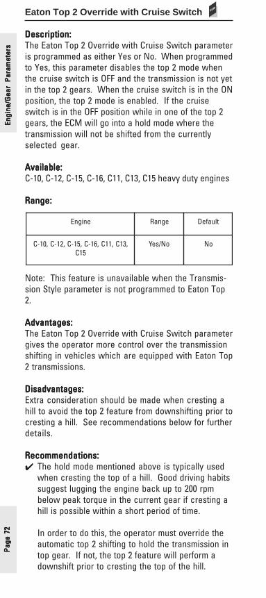
Page
72
Page
72
Page
72
Page
72
Page
72
Eaton Top 2 Override with Cruise Switch
Description:Description:Description:Description:Description:The Eaton Top 2 Override with Cruise Switch parameteris programmed as either Yes or No. When programmedto Yes, this parameter disables the top 2 mode whenthe cruise switch is OFF and the transmission is not yetin the top 2 gears. When the cruise switch is in the ONposition, the top 2 mode is enabled. If the cruiseswitch is in the OFF position while in one of the top 2gears, the ECM will go into a hold mode where thetransmission will not be shifted from the currentlyselected gear.
Available:Available:Available:Available:Available:C-10, C-12, C-15, C-16, C11, C13, C15 heavy duty engines
Range:Range:Range:Range:Range:
Note: This feature is unavailable when the Transmis-sion Style parameter is not programmed to Eaton Top2.
Advantages:Advantages:Advantages:Advantages:Advantages:The Eaton Top 2 Override with Cruise Switch parametergives the operator more control over the transmissionshifting in vehicles which are equipped with Eaton Top2 transmissions.
Disadvantages:Disadvantages:Disadvantages:Disadvantages:Disadvantages:Extra consideration should be made when cresting ahill to avoid the top 2 feature from downshifting prior tocresting a hill. See recommendations below for furtherdetails.
Recommendations:Recommendations:Recommendations:Recommendations:Recommendations:✔ The hold mode mentioned above is typically used
when cresting the top of a hill. Good driving habitssuggest lugging the engine back up to 200 rpmbelow peak torque in the current gear if cresting ahill is possible within a short period of time.
In order to do this, the operator must override theautomatic top 2 shifting to hold the transmission intop gear. If not, the top 2 feature will perform adownshift prior to cresting the top of the hill.
enignE egnaR tluafeD
,31C,11C,61-C,51-C,21-C,01-C51C
oN/seY oN
Engi
ne/G
ear
Para
met
ers
Engi
ne/G
ear
Para
met
ers
Engi
ne/G
ear
Para
met
ers
Engi
ne/G
ear
Para
met
ers
Engi
ne/G
ear
Para
met
ers
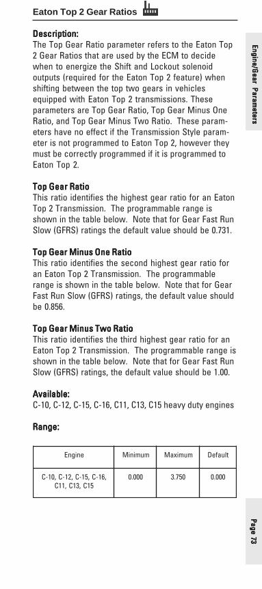
Page 73Page 73Page 73Page 73Page 73
Eaton Top 2 Gear Ratios
Description:Description:Description:Description:Description:The Top Gear Ratio parameter refers to the Eaton Top2 Gear Ratios that are used by the ECM to decidewhen to energize the Shift and Lockout solenoidoutputs (required for the Eaton Top 2 feature) whenshifting between the top two gears in vehiclesequipped with Eaton Top 2 transmissions. Theseparameters are Top Gear Ratio, Top Gear Minus OneRatio, and Top Gear Minus Two Ratio. These param-eters have no effect if the Transmission Style param-eter is not programmed to Eaton Top 2, however theymust be correctly programmed if it is programmed toEaton Top 2.
Top Gear RatioTop Gear RatioTop Gear RatioTop Gear RatioTop Gear RatioThis ratio identifies the highest gear ratio for an EatonTop 2 Transmission. The programmable range isshown in the table below. Note that for Gear Fast RunSlow (GFRS) ratings the default value should be 0.731.
Top Gear Minus One RatioTop Gear Minus One RatioTop Gear Minus One RatioTop Gear Minus One RatioTop Gear Minus One RatioThis ratio identifies the second highest gear ratio foran Eaton Top 2 Transmission. The programmablerange is shown in the table below. Note that for GearFast Run Slow (GFRS) ratings, the default value shouldbe 0.856.
Top Gear Minus Two RatioTop Gear Minus Two RatioTop Gear Minus Two RatioTop Gear Minus Two RatioTop Gear Minus Two RatioThis ratio identifies the third highest gear ratio for anEaton Top 2 Transmission. The programmable range isshown in the table below. Note that for Gear Fast RunSlow (GFRS) ratings, the default value should be 1.00.
Available:Available:Available:Available:Available:C-10, C-12, C-15, C-16, C11, C13, C15 heavy duty engines
Range:Range:Range:Range:Range:
enignE muminiM mumixaM tluafeD
,61-C,51-C,21-C,01-C51C,31C,11C
000.0 057.3 000.0
Engine/Gear Param
etersEngine/G
ear Parameters
Engine/Gear Param
etersEngine/G
ear Parameters
Engine/Gear Param
eters

Page
74
Page
74
Page
74
Page
74
Page
74
Note: The XX appearing in the transmission modelnumber refers to (x) 100=Nominal Torque Capacity. Forexample, RTLO-14613A has a Nominal Torque capacityof 14 (x) 100 or 1400 lb ft. The transmission modeldesignation and other transmission identificationinformation are stamped on the transmission tag onthe lower left side near the front of the transmission.
Advantages:Advantages:Advantages:Advantages:Advantages:When properly programmed, these parameters allowthe Eaton Top 2 Transmission to effectively controlautomatic shifting in the top 2 gears.
Disadvantages:Disadvantages:Disadvantages:Disadvantages:Disadvantages:None
Recommendations:Recommendations:Recommendations:Recommendations:Recommendations:✔ These parameters must be precisely programmed
to three decimal places to ensure proper operationof the Eaton Top 2 transmission and the engine inthe top 2 gears. Not programming this parameterprecisely may result in a 253-11 Check TransmissionCustomer Parameters diagnostic code.
Engi
ne/G
ear
Para
met
ers
Engi
ne/G
ear
Para
met
ers
Engi
ne/G
ear
Para
met
ers
Engi
ne/G
ear
Para
met
ers
Engi
ne/G
ear
Para
met
ers
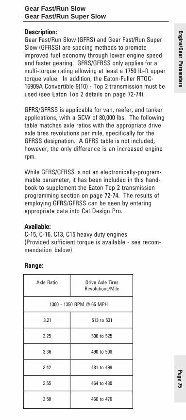
Page 75Page 75Page 75Page 75Page 75
Gear Fast/Run SlowGear Fast/Run Super Slow
Description:Description:Description:Description:Description:Gear Fast/Run Slow (GFRS) and Gear Fast/Run SuperSlow (GFRSS) are specing methods to promoteimproved fuel economy through lower engine speedand faster gearing. GFRS/GFRSS only applies for amulti-torque rating allowing at least a 1750 lb-ft uppertorque value. In addition, the Eaton-Fuller RTOC-16909A Convertible 9(10) - Top 2 transmission must beused (see Eaton Top 2 details on page 72-74).
GFRS/GFRSS is applicable for van, reefer, and tankerapplications, with a GCW of 80,000 lbs. The followingtable matches axle ratios with the appropriate driveaxle tires revolutions per mile, specifically for theGFRSS designation. A GFRS table is not included,however, the only difference is an increased enginerpm.
While GFRS/GFRSS is not an electronically-program-mable parameter, it has been included in this hand-book to supplement the Eaton Top 2 transmissionprogramming section on page 72-74. The results ofemploying GFRS/GFRSS can be seen by enteringappropriate data into Cat Design Pro.
Available:Available:Available:Available:Available:C-15, C-16, C13, C15 heavy duty engines(Provided sufficient torque is available - see recom-mendation below)
Range:Range:Range:Range:Range:
oitaRelxA seriTelxAevirDeliM/snoituloveR
HPM56@MPR0531-0031
12.3 135ot315
52.3 525ot605
63.3 805ot094
24.3 994ot184
55.3 084ot464
85.3 674ot064
Engine/Gear Param
etersEngine/G
ear Parameters
Engine/Gear Param
etersEngine/G
ear Parameters
Engine/Gear Param
eters

Page
76
Page
76
Page
76
Page
76
Page
76
Recommendations:Recommendations:Recommendations:Recommendations:Recommendations:✔ Caterpillar recommends that the engine have at
least 1650 lb-ft of torque available for GFRS✔ Caterpillar recommends that the engine have at
least 1750 lb-ft of torque available for GFRSS
Engi
ne/G
ear
Para
met
ers
Engi
ne/G
ear
Para
met
ers
Engi
ne/G
ear
Para
met
ers
Engi
ne/G
ear
Para
met
ers
Engi
ne/G
ear
Para
met
ers

Page 77Page 77Page 77Page 77Page 77
AT/MT/HT Part Throttle Shift Speed
Description:Description:Description:Description:Description:The AT/MT/HT Part Throttle Shift Speed parameterprovides the ability to change the shifting characteris-tics in vehicles equipped with non-data link capableAllison transmissions. The Allison AT/MT/HT (nonelec-tronic) transmissions require an input from the engineECM to regulate transmission shifting. The ECMmonitors accelerator pedal position, engine speed,load, and cruise control status to determine if thetransmission should use closed throttle or full throttleshift modulation.
Programming the Transmission Style parameter to oneof the AT/MT/HT options activates ECM Output #7 (J1/P1:20) to control a shift interface relay connected tothe transmission. The ECM can then energize theoutput when the transmission should use full throttlemodulation (performance mode) or disable the outputwhen the transmission should use closed throttlemodulation (economy mode).
Available:Available:Available:Available:Available:3126E, C7, and C9 medium duty engines
Range:Range:Range:Range:Range:
Advantages:Advantages:Advantages:Advantages:Advantages:This parameter provides additional control overshifting characteristics of the non-data link capableAllison transmissions. This additional control enablesa driver to optimize the transmission’s behaviordepending upon the specific application.
Disadvantages:Disadvantages:Disadvantages:Disadvantages:Disadvantages:None
sevitanretlA tluafeD
)elbasiD%56/elbanE%08(woL)elbasiD%55/lbanE%07(muideM
%54/elbanE%06(hgiH)elbasiD
Engine/Gear Param
etersEngine/G
ear Parameters
Engine/Gear Param
etersEngine/G
ear Parameters
Engine/Gear Param
eters

Page
78
Page
78
Page
78
Page
78
Page
78
Governor Type
Description:Description:Description:Description:Description:Caterpillar offers three governor options, selectablewith the Governor Type parameter. These threeoptions are the Full Range Governor, and two types ofthe Min/Max Governor.
Full Range GovernorFull Range GovernorFull Range GovernorFull Range GovernorFull Range GovernorThis governor type allows the engine to maintainengine speed for a given throttle position. The FullRange Governor is capable of injecting the maximumamount of fuel for a given desired engine speed.
The Full Range Governor is very sensitive to changesin engine speed, and is therefore not the preferredand is therefore not the preferredand is therefore not the preferredand is therefore not the preferredand is therefore not the preferredgovernor type for vehicles using automatic transmis-governor type for vehicles using automatic transmis-governor type for vehicles using automatic transmis-governor type for vehicles using automatic transmis-governor type for vehicles using automatic transmis-sions.sions.sions.sions.sions. For example, if the ECM wants to maintain 1500rpm, the governor will try to maintain the desiredspeed. When an automatic transmission performs anupshift, the actual engine speed will fall below thedesired engine speed of 1500 rpm. The Full RangeGovernor would then inject a large amount of fuel inan attempt to increase the engine speed back up tothe desired engine speed of 1500 rpm. This causesundesirable, harsh shifting with an automatic transmis-sion.
Min/Max GovernorMin/Max GovernorMin/Max GovernorMin/Max GovernorMin/Max GovernorThe Min/Max Governor, however, is well-suited forvehicles with automatic transmissions. The Min/Maxgovernor will only control engine speed when at theminimum (low idle) or maximum (top engine limit)allowed engine speed. When in between these twoextremes, the engine will produce the power propor-tional to the throttle position. This results in smoothershifting with automatic/automated transmissions.
The Min/Max Governor optimizes automatic transmis-sion shift quality and power modulation, allowing theoperator to adjust the engine power output to matchtypical vehicle operating conditions. The enginespeed will vary to find a vehicle load level which willmatch the engine power output specified by thethrottle. If the throttle is commanding more powerthan the vehicle load will offer, the engine willaccelerate to the top engine limit. This makes it verydifficult to maintain a constant engine speed when thevehicle is parked. Slightly depressing the throttlepedal with the vehicle parked will cause the engine togo to the top engine limit, which may be undesirable
Engi
ne/G
ear
Para
met
ers
Engi
ne/G
ear
Para
met
ers
Engi
ne/G
ear
Para
met
ers
Engi
ne/G
ear
Para
met
ers
Engi
ne/G
ear
Para
met
ers

Page 79Page 79Page 79Page 79Page 79
for applications that require precise engine speedcontrol while parked. This problem can be solved bythe third governor type.
Min/Max Governor with Speed ControlMin/Max Governor with Speed ControlMin/Max Governor with Speed ControlMin/Max Governor with Speed ControlMin/Max Governor with Speed ControlThe Min/Max Governor with Speed Control offers thebest combination of the Full Range Governor and theMin/Max Governor. It provides smooth shifting withautomatic/automated transmissions while driving, andprecise engine speed control when the vehicle isparked.
Available:Available:Available:Available:Available:All electronically controlled on-highway enginescovered in this handbook(Note: Excludes C-10, C-12, C-15, C-16 PM OCT01)
Range:Range:Range:Range:Range:
Advantages:Advantages:Advantages:Advantages:Advantages:The Governor Type parameter allows the operator tocustomize engine speed control by specifying theappropriate governor for the selected transmissiontype. When the Governor Type is properly set asrecommended below, optimum engine speed control isachieved.
Disadvantages:Disadvantages:Disadvantages:Disadvantages:Disadvantages:None
Recommendations:Recommendations:Recommendations:Recommendations:Recommendations:✔ The Full Range Governor is recommended for
vehicles with manual transmissions.✔ The Min/Max Governor is recommended for
vehicles with automatic/automated transmissions.✔ The Min/Max Governor with Speed Control is
recommended for all automatic/automated trans-mission-equipped vehicles with that requireprecise engine speed control when parked.
enignE egnaR tluafeD
9C,7C,E6213)erofebdna30RAMMP(
61-C,51-C,21-C,01-C)20TCOMP-20NAJMP(
xaM/niM egnaRlluF
9C,7C,E6213)retfadna40RAMMP(
51C,31C,11C
htiwxaM/niM,lortnoCdeepS
xaM/niM
egnaRlluF
Engine/Gear Param
etersEngine/G
ear Parameters
Engine/Gear Param
etersEngine/G
ear Parameters
Engine/Gear Param
eters
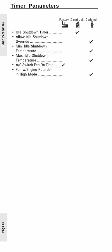
Page
80
Page
80
Page
80
Page
80
Page
80
Tim
er P
aram
eter
sTi
mer
Par
amet
ers
Tim
er P
aram
eter
sTi
mer
Par
amet
ers
Tim
er P
aram
eter
sTimer Parameters
Factory Databook Optional
• Idle Shutdown Timer ............... ✔• Allow Idle Shutdown
Override ..................................... ✔• Min. Idle Shutdown
Temperature ............................. ✔• Max. Idle Shutdown
Temperature ............................. ✔• A/C Switch Fan On Time ........✔• Fan w/Engine Retarder
in High Mode ............................ ✔
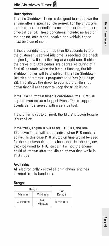
Page 81Page 81Page 81Page 81Page 81
Idle Shutdown Timer
Description:Description:Description:Description:Description:The Idle Shutdown Timer is designed to shut down theengine after a specified idle period. For the shutdownto occur, certain conditions must be met for the entiretime-out period. These conditions include: no load onthe engine, cold mode inactive and vehicle speedmust be 0 (zero) mph.
If these conditions are met, then 90 seconds beforethe customer specified idle time is reached, the checkengine light will start flashing at a rapid rate. If eitherthe brake or clutch pedals are depressed during thisfinal 90 seconds when the lamp is flashing, the idleshutdown timer will be disabled, if the Idle ShutdownOverride parameter is programmed to Yes (see page83). This allows the driver to override the idle shut-down timer if necessary to keep the truck idling.
If the idle shutdown timer is overridden, the ECM willlog the override as a Logged Event. These LoggedEvents can be viewed with a service tool.
If the timer is set to 0 (zero), the Idle Shutdown featureis turned off.
If the truck/engine is wired for PTO use, the IdleShutdown Timer will not be active when PTO mode isactive. In this case PTO shutdown time would be usedfor the shutdown time. It is important that the engine/truck be wired for PTO, since if it is not, the enginecould shutdown after the idle shutdown time while inPTO mode
Available:Available:Available:Available:Available:All electronically controlled on-highway enginescovered in this handbook.
Range:Range:Range:Range:Range:
egnaR taCtluafeDmuminiM mumixaM
setuniM3 0441setuniM setuniM0
Timer Param
etersTim
er Parameters
Timer Param
etersTim
er Parameters
Timer Param
eters
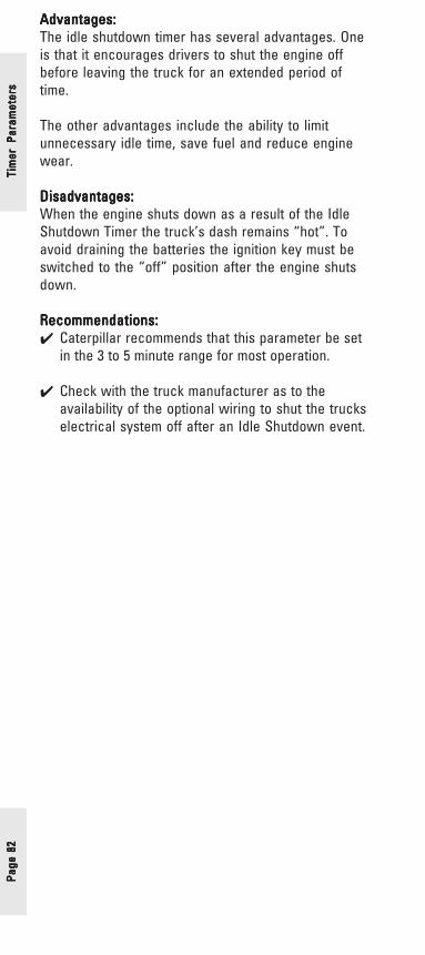
Page
82
Page
82
Page
82
Page
82
Page
82
Tim
er P
aram
eter
sTi
mer
Par
amet
ers
Tim
er P
aram
eter
sTi
mer
Par
amet
ers
Tim
er P
aram
eter
sAdvantages:Advantages:Advantages:Advantages:Advantages:The idle shutdown timer has several advantages. Oneis that it encourages drivers to shut the engine offbefore leaving the truck for an extended period oftime.
The other advantages include the ability to limitunnecessary idle time, save fuel and reduce enginewear.
Disadvantages:Disadvantages:Disadvantages:Disadvantages:Disadvantages:When the engine shuts down as a result of the IdleShutdown Timer the truck’s dash remains “hot”. Toavoid draining the batteries the ignition key must beswitched to the “off” position after the engine shutsdown.
Recommendations:Recommendations:Recommendations:Recommendations:Recommendations:✔ Caterpillar recommends that this parameter be set
in the 3 to 5 minute range for most operation.
✔ Check with the truck manufacturer as to theavailability of the optional wiring to shut the truckselectrical system off after an Idle Shutdown event.

Page 83Page 83Page 83Page 83Page 83
Allow Idle Shutdown Override
Description:Description:Description:Description:Description:The Allow Idle Shutdown Override parameter deter-mines whether the clutch or service brake can beused to override the Idle Shutdown Timer during thelast 90 seconds of timing. The Idle Shutdown Timerparameter must be programmed to a value other than 0(zero). The Allow Idle Shutdown Override parameterhas three different settings.
YesYesYesYesYes - Allows the driver to override the Idle ShutdownTimer during the last 90 seconds of timing. (Ifthe driver does override the timer an IdleShutdown Override Event will be logged in theECM memory)
NoNoNoNoNo - The driver can notnotnotnotnot override the Idle ShutdownTimer during the last 90 seconds of timing. Inother words, the truck will always shutdown.(When the engine does shutdown at the endof the Idle Shutdown Time period an IdleShutdown Occurrence event will be logged inthe ECM memory).
Outside Temperature BasedOutside Temperature BasedOutside Temperature BasedOutside Temperature BasedOutside Temperature Based - If the truck has theoptional Outside Air Temperature Sensorinstalled (see authorized Cat Dealer or truckOEM for part number) and the Minimum andMaximum Idle Shutdown Outside Temperatureparameters are properly programmed (seepage 85), then Idle Shutdown will be based onthe Outside Air Temperature.
Available:Available:Available:Available:Available:All electronically controlled on-highway enginescovered in this handbook
Range:Range:Range:Range:Range:
enignE sevitanretlA tluafeD
,7C,E62139C oN seY
,21-C,01-C,61-C,51-C
,31C,11C51C
.pmeTedistuO,oNedistuO7851J,desaB
desaB.pmeTseY
Timer Param
etersTim
er Parameters
Timer Param
etersTim
er Parameters
Timer Param
eters
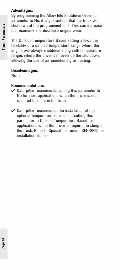
Page
84
Page
84
Page
84
Page
84
Page
84
Tim
er P
aram
eter
sTi
mer
Par
amet
ers
Tim
er P
aram
eter
sTi
mer
Par
amet
ers
Tim
er P
aram
eter
s
Advantages:Advantages:Advantages:Advantages:Advantages:By programming the Allow Idle Shutdown Overrideparameter to No, it is guaranteed that the truck willshutdown at the programmed time. This can increasefuel economy and decrease engine wear.
The Outside Temperature Based setting allows theflexibility of a defined temperature range where theengine will always shutdown along with temperatureranges where the driver can override the shutdown,allowing the use of air conditioning or heating.
Disadvantages:Disadvantages:Disadvantages:Disadvantages:Disadvantages:None
Recommendations:Recommendations:Recommendations:Recommendations:Recommendations:✔ Caterpillar recommends setting this parameter to
No for most applications when the driver is notrequired to sleep in the truck.
✔ Caterpillar recommends the installation of theoptional temperature sensor and setting thisparameter to Outside Temperature Based forapplications when the driver is required to sleep inthe truck. Refer to Special Instruction SEHS9920 forinstallation details.

Page 85Page 85Page 85Page 85Page 85
Minimum Idle Shutdown Outside TemperatureMaximum Idle Shutdown Outside Temperature
Description:Description:Description:Description:Description:The Minimum and Maximum Idle Shutdown Tempera-ture settings allow the flexibility of a defined tempera-ture range where the engine will always shutdownalong with temperature ranges where the driver canoverride the shutdown, allowing the use of air condi-tioning or heating. The Allow Idle Shutdown Overrideparameter must be programmed to “Outside Tempera-ture Based” for these parameters to be programmed(See page 83).
Available:Available:Available:Available:Available:All on-highway engines covered in this handbook.
Range:Range:Range:Range:Range:
Advantages:Advantages:Advantages:Advantages:Advantages:The Outside Temperature Based Shutdown saves fuelby allowing idle only when necessary for drivercomfort.
Disadvantages:Disadvantages:Disadvantages:Disadvantages:Disadvantages:If the Idle Shutdown time is programmed for a longtime (more than an hour) and the temperature drops into the “Always Shutdown” range the engine wouldshutdown and could wake the driver.
Recommendations:Recommendations:Recommendations:Recommendations:Recommendations:✔ Program the Minimum setting to a value where it
would be necessary to use the heater to becomfortable and the Maximum setting to a valuewhere it would be necessary to use the air condi-tioner to be comfortable.
egnaR taCtluafeDmuminiM mumixaM
F°04-)C°04-(
F°021)C°94(
F°021)C°94(
Timer Param
etersTim
er Parameters
Timer Param
etersTim
er Parameters
Timer Param
eters
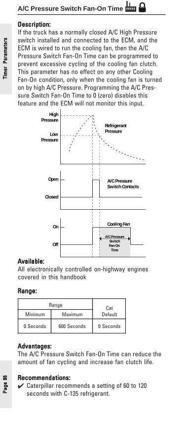
Page
86
Page
86
Page
86
Page
86
Page
86
Tim
er P
aram
eter
sTi
mer
Par
amet
ers
Tim
er P
aram
eter
sTi
mer
Par
amet
ers
Tim
er P
aram
eter
sA/C Pressure Switch Fan-On Time
Description:Description:Description:Description:Description:If the truck has a normally closed A/C High Pressureswitch installed and connected to the ECM, and theECM is wired to run the cooling fan, then the A/CPressure Switch Fan-On Time can be programmed toprevent excessive cycling of the cooling fan clutch.This parameter has no effect on any other CoolingFan-On condition, only when the cooling fan is turnedon by high A/C Pressure. Programming the A/C Pres-sure Switch Fan-On Time to 0 (zero) disables thisfeature and the ECM will not monitor this input.
Open
Closed
On
Off
LowPressure
HighPressure
RefrigerantPressure
A/C PressureSwitch Contacts
Cooling Fan
A/C PressureSwitchFan-On
Time
Available:Available:Available:Available:Available:All electronically controlled on-highway enginescovered in this handbook
Range:Range:Range:Range:Range:
Advantages:Advantages:Advantages:Advantages:Advantages:The A/C Pressure Switch Fan-On Time can reduce theamount of fan cycling and increase fan clutch life.
Recommendations:Recommendations:Recommendations:Recommendations:Recommendations:✔ Caterpillar recommends a setting of 60 to 120
seconds with C-135 refrigerant.
egnaR taCtluafeDmuminiM mumixaM
sdnoceS0 sdnoceS006 sdnoceS0
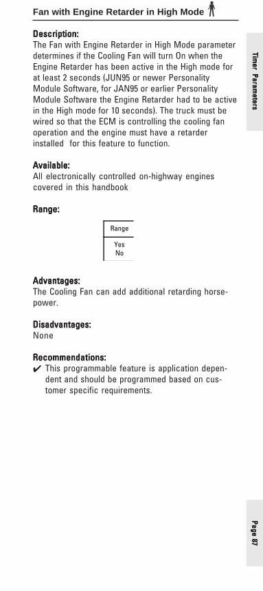
Page 87Page 87Page 87Page 87Page 87
Fan with Engine Retarder in High Mode
Description:Description:Description:Description:Description:The Fan with Engine Retarder in High Mode parameterdetermines if the Cooling Fan will turn On when theEngine Retarder has been active in the High mode forat least 2 seconds (JUN95 or newer PersonalityModule Software, for JAN95 or earlier PersonalityModule Software the Engine Retarder had to be activein the High mode for 10 seconds). The truck must bewired so that the ECM is controlling the cooling fanoperation and the engine must have a retarderinstalled for this feature to function.
Available:Available:Available:Available:Available:All electronically controlled on-highway enginescovered in this handbook
Range:Range:Range:Range:Range:
Range
YesNo
Advantages:Advantages:Advantages:Advantages:Advantages:The Cooling Fan can add additional retarding horse-power.
Disadvantages:Disadvantages:Disadvantages:Disadvantages:Disadvantages:None
Recommendations:Recommendations:Recommendations:Recommendations:Recommendations:✔ This programmable feature is application depen-
dent and should be programmed based on cus-tomer specific requirements.
Timer Param
etersTim
er Parameters
Timer Param
etersTim
er Parameters
Timer Param
eters

Page
88
Page
88
Page
88
Page
88
Page
88
Exhaust Brake Parameters
Factory Databook Optional
• Exhaust Brake Configuration ✔
Exha
ust
Bra
ke P
aram
eter
sEx
haus
t B
rake
Par
amet
ers
Exha
ust
Bra
ke P
aram
eter
sEx
haus
t B
rake
Par
amet
ers
Exha
ust
Bra
ke P
aram
eter
s

Page 89Page 89Page 89Page 89Page 89
Exhaust Brake Configuration
Description:Description:Description:Description:Description:The Exhaust Brake Configuration parameter deter-mines the functionality of the exhaust brake. Thisparameter can be programmed to one of the followingoptions: None, Warm Up Device Only, Exhaust BrakeOnly, or Exhaust Brake & Warm Up Device.
The exhaust brake can be used to apply a parasiticload to the engine in order to aid engine warm up toachieve normal operating temperature quicker. To usethis feature, the Exhaust Brake Configuration param-eter must be set to either Warm Up Device Only orExhaust Brake and Warm Up Device. Also, the WarmUp Mode Idle Speed parameter must be programmedto an engine speed between 700 rpm and 1400 rpm. Ifthese preceding conditions are met, then the enginewill ramp up to the programmed Warm Up Mode IdleSpeed parameter value when the intake air tempera-ture is below 50 degrees Fahrenheit and the coolanttemperature is below 160 degrees Fahrenheit.
Available:Available:Available:Available:Available:3126E, C7, and C9 medium duty engines
Range:Range:Range:Range:Range:
Advantages:Advantages:Advantages:Advantages:Advantages:This parameter allows an operator to use the installedexhaust brake on his/her vehicle to act as an exhaustbrake, a warm up device to help the engine achieveoperating temperature quicker, or a combination of thetwo. This allows flexibility in the use of the exhaustbrake depending upon the specific application.
Disadvantages:Disadvantages:Disadvantages:Disadvantages:Disadvantages:None
enignE sevitanretlA tluafeD
9C,7C,E6213rehtO
pUmraW,enoNekarBtsuahxE,ylnO
pUmraW&
tsuahxEylnOekarB
9C,7C)retfadna40RAMMP(
065TMG
,ylnOpUmraW&ekarBtsuahxE
tsuahxE,pUmraWylnOekarB
enoN
Exhaust Brake Param
etersExhaust B
rake Parameters
Exhaust Brake Param
etersExhaust B
rake Parameters
Exhaust Brake Param
eters
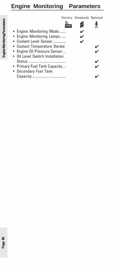
Page
90
Page
90
Page
90
Page
90
Page
90
Engine Monitoring Parameters
Factory Databook Optional
• Engine Monitoring Mode ....... ✔• Engine Monitoring Lamps...... ✔• Coolant Level Sensor .............. ✔• Coolant Temperature Derate ✔• Engine Oil Pressure Sensor ... ✔• Oil Level Switch Installation
Status ......................................... ✔• Primary Fuel Tank Capacity ... ✔• Secondary Fuel Tank
Capacity ..................................... ✔
Engi
ne M
onito
ring P
aram
eter
sEn
gine
Mon
itorin
g Par
amet
ers
Engi
ne M
onito
ring P
aram
eter
sEn
gine
Mon
itorin
g Par
amet
ers
Engi
ne M
onito
ring P
aram
eter
s
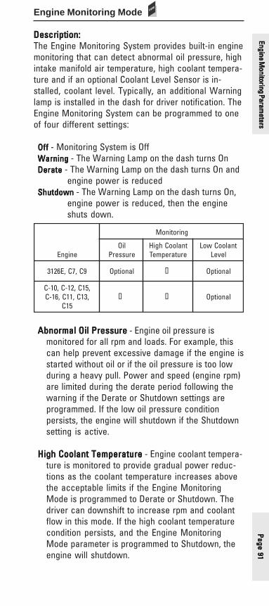
Page 91Page 91Page 91Page 91Page 91
Engine Monitoring Mode
Description:Description:Description:Description:Description:The Engine Monitoring System provides built-in enginemonitoring that can detect abnormal oil pressure, highintake manifold air temperature, high coolant tempera-ture and if an optional Coolant Level Sensor is in-stalled, coolant level. Typically, an additional Warninglamp is installed in the dash for driver notification. TheEngine Monitoring System can be programmed to oneof four different settings:
OffOffOffOffOff - Monitoring System is OffWarningWarningWarningWarningWarning - The Warning Lamp on the dash turns OnDerateDerateDerateDerateDerate - The Warning Lamp on the dash turns On and
engine power is reducedShutdownShutdownShutdownShutdownShutdown - The Warning Lamp on the dash turns On,
engine power is reduced, then the engineshuts down.
Abnormal Oil PressureAbnormal Oil PressureAbnormal Oil PressureAbnormal Oil PressureAbnormal Oil Pressure - Engine oil pressure ismonitored for all rpm and loads. For example, thiscan help prevent excessive damage if the engine isstarted without oil or if the oil pressure is too lowduring a heavy pull. Power and speed (engine rpm)are limited during the derate period following thewarning if the Derate or Shutdown settings areprogrammed. If the low oil pressure conditionpersists, the engine will shutdown if the Shutdownsetting is active.
High Coolant TemperatureHigh Coolant TemperatureHigh Coolant TemperatureHigh Coolant TemperatureHigh Coolant Temperature - Engine coolant tempera-ture is monitored to provide gradual power reduc-tions as the coolant temperature increases abovethe acceptable limits if the Engine MonitoringMode is programmed to Derate or Shutdown. Thedriver can downshift to increase rpm and coolantflow in this mode. If the high coolant temperaturecondition persists, and the Engine MonitoringMode parameter is programmed to Shutdown, theengine will shutdown.
enignE
gnirotinoM
liOerusserP
tnalooChgiHerutarepmeT
tnalooCwoLleveL
9C,7C,E6213 lanoitpO � lanoitpO
,51C,21-C,01-C,31C,11C,61-C
51C� � lanoitpO
Engine Monitoring Param
etersEngine M
onitoring Parameters
Engine Monitoring Param
etersEngine M
onitoring Parameters
Engine Monitoring Param
eters

Page
92
Page
92
Page
92
Page
92
Page
92
Example: Coolant Temperature Derate/ ShutdownRated Hp = 400 HpRated Hp = 400 HpRated Hp = 400 HpRated Hp = 400 HpRated Hp = 400 HpDelta Hp = 240 Hp = 400 Hp - 160 HpDelta Hp = 240 Hp = 400 Hp - 160 HpDelta Hp = 240 Hp = 400 Hp - 160 HpDelta Hp = 240 Hp = 400 Hp - 160 HpDelta Hp = 240 Hp = 400 Hp - 160 Hp
As Coolant temperature rises to 217°F (103°C) theengine is derated by 25% of the Delta Hp. In thisexample 240 Hp x .25 = 60 Hp. The driver wouldhave 340 Hp available. If the driver reacted bydownshifting, for example, and the temperaturedid not rise, the power would stay at this level.
However, if the coolant temperature continued toincrease, to 219°F (104°C) the driver would loseanother 25% or 60 Hp and have 280 Hp in thisexample.
If the temperature continues to rise to 223°F(106°C) the maximum derate would occur. In thisexample 100% of the Delta Hp or 240 Hp. The truckwould be limited to 160 Hp or 45 MPH (72.5 km/h)which ever occurs first.
If Shutdown has been selected as the EngineMonitoring Mode, and the temperature remainedabove 223°F (106°C) the engine would shutdown20 seconds after the maximum derate had beenreached. (Shutdown Mode is not available forBrakeSaver equipped engines.)
Low Coolant LevelLow Coolant LevelLow Coolant LevelLow Coolant LevelLow Coolant Level - Coolant level is monitored if anOEM sensor is installed and the coolant leveloption is activated (See page 95). To avoid “falsealarms” a warning delay or “debounce” periodprevents the system from warning the driver if thecoolant level fluctuates rapidly, such as it couldwhile traversing bumpy terrain. Vehicle speed islimited during the derate period following thewarning if Derate or Shutdown settings areprogrammed. If the low coolant level persists theengine will shutdown if the Shutdown mode hasbeen selected.
Engi
ne M
onito
ring P
aram
eter
sEn
gine
Mon
itorin
g Par
amet
ers
Engi
ne M
onito
ring P
aram
eter
sEn
gine
Mon
itorin
g Par
amet
ers
Engi
ne M
onito
ring P
aram
eter
s
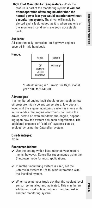
Page 93Page 93Page 93Page 93Page 93
High Inlet Manifold Air TemperatureHigh Inlet Manifold Air TemperatureHigh Inlet Manifold Air TemperatureHigh Inlet Manifold Air TemperatureHigh Inlet Manifold Air Temperature - While thisfeature is part of the monitoring system it will notit will notit will notit will notit will notaffect operation of the engine other than theaffect operation of the engine other than theaffect operation of the engine other than theaffect operation of the engine other than theaffect operation of the engine other than thenormal power loss you would experience withoutnormal power loss you would experience withoutnormal power loss you would experience withoutnormal power loss you would experience withoutnormal power loss you would experience withouta monitoring system. a monitoring system. a monitoring system. a monitoring system. a monitoring system. The driver will simply bealerted and a fault logged as it is when any one ofthe monitored conditions exceeds acceptablelimits.
Available:Available:Available:Available:Available:All electronically controlled on-highway enginescovered in this handbook
Range:Range:Range:Range:Range:
*Default setting is “Derate” for C7,C9 modelyear 2003 for GMT560
Advantages:Advantages:Advantages:Advantages:Advantages:If a monitored engine fault should occur, such as lowoil pressure, high coolant temperature, low coolantlevel, and the engine monitoring system is in one of itsactive modes, the engine electronics can warn thedriver, derate or even shutdown the engine, depend-ing upon how the system has been programmed. Theadditional expense of “add-on” systems can beavoided by using the Caterpillar system.
Disadvantages:Disadvantages:Disadvantages:Disadvantages:Disadvantages:None
Recommendations:Recommendations:Recommendations:Recommendations:Recommendations:✔ Use the setting which best matches your require-
ments, however, Caterpillar recommends using theShutdown mode for most applications.
✔ If another monitoring system is used, set theCaterpillar system to Off to avoid interaction withthe installed system.
✔ When specing your truck ask that the coolant levelsensor be installed and activated. This may be anadditional cost option, but less than the cost ofanother monitoring system.
egnaR tluafeD
ffOgninraW
etareDnwodtuhS
*gninraW
Engine Monitoring Param
etersEngine M
onitoring Parameters
Engine Monitoring Param
etersEngine M
onitoring Parameters
Engine Monitoring Param
eters

Page
94
Page
94
Page
94
Page
94
Page
94
Engine Monitoring Lamps
Description:Description:Description:Description:Description:This parameter determines the lamp requirements forthe Engine Monitoring System. When programmed tothe Warning Lamp option, one lamp connected to J1/P1:29, is used to indicate potentially damaging engineconditions.
When programmed to Option 1, up to three discretelamp outputs are available to indicate specific engineproblems. Option 1 configures J1/P1:29 for connectionof a Low Oil Pressure Warning Lamp, J1/P1:31 forconnection of a High Coolant Temperature WarningLamp. J1/P1:30 may used to connect a Low CoolantLevel Warning Lamp if the Coolant Level Sensor isprogrammed to other “No”. If the Coolant Level Sensorparameter is programmed to No, then J1/P1:30 can beused to connect a PTO Switch On Lamp.
For GMT530 trucks, this parameter may be programmedto High Coolant Temp Warning Lamp. The optionalsetting configures the ECM to provide an indicationwhen engine coolant temperature is abnormally high.This circuit is used to interface the GM VehicleShutdown System. When programmed to the HighCoolant Temp Warning Lamp setting, J1/P1:29 is notavailable for use as a Warning Lamp for the CaterpillarEngine Monitoring System.
Available:Available:Available:Available:Available:All electronically controlled on-highway enginescovered in this handbook
Range:Range:Range:Range:Range:
enignE sevitanretlA tluafeD
E6213MG
pmettnaloochgiHpmalgninraw
gninraWpmal
rehtOE6213065TMG9C/7C
AN AN
9C/7C045/035MG
pmettnaloochgiHpmalgninraw
gninraWpmal
DHrehtO9C/7C
1noitpO gninraWpmaL
Engi
ne M
onito
ring P
aram
eter
sEn
gine
Mon
itorin
g Par
amet
ers
Engi
ne M
onito
ring P
aram
eter
sEn
gine
Mon
itorin
g Par
amet
ers
Engi
ne M
onito
ring P
aram
eter
s
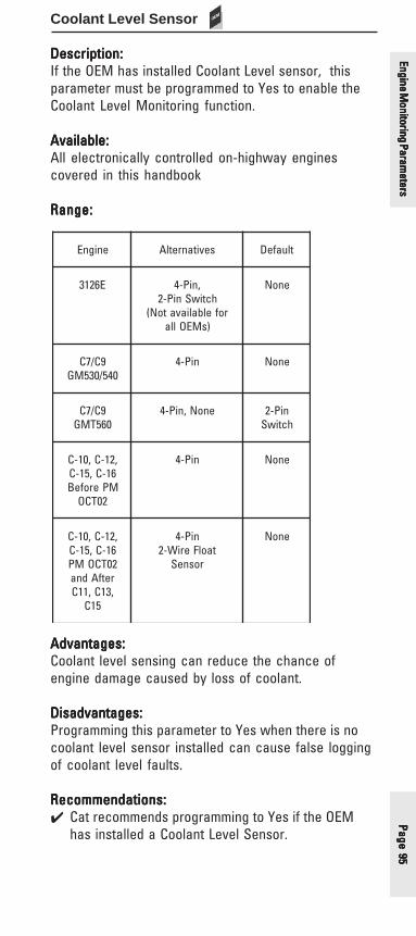
Page 95Page 95Page 95Page 95Page 95
Coolant Level Sensor
Description:Description:Description:Description:Description:If the OEM has installed Coolant Level sensor, thisparameter must be programmed to Yes to enable theCoolant Level Monitoring function.
Available:Available:Available:Available:Available:All electronically controlled on-highway enginescovered in this handbook
Range:Range:Range:Range:Range:
Advantages:Advantages:Advantages:Advantages:Advantages:Coolant level sensing can reduce the chance ofengine damage caused by loss of coolant.
Disadvantages:Disadvantages:Disadvantages:Disadvantages:Disadvantages:Programming this parameter to Yes when there is nocoolant level sensor installed can cause false loggingof coolant level faults.
Recommendations:Recommendations:Recommendations:Recommendations:Recommendations:✔ Cat recommends programming to Yes if the OEM
has installed a Coolant Level Sensor.
enignE sevitanretlA tluafeD
E6213 ,niP-4hctiwSniP-2
rofelbaliavatoN()sMEOlla
enoN
9C/7C045/035MG
niP-4 enoN
9C/7C065TMG
enoN,niP-4 niP-2hctiwS
,21-C,01-C61-C,51-CMPerofeB
20TCO
niP-4 enoN
,21-C,01-C61-C,51-C20TCOMPretfAdna,31C,11C
51C
niP-4taolFeriW-2
rosneS
enoN
Engine Monitoring Param
etersEngine M
onitoring Parameters
Engine Monitoring Param
etersEngine M
onitoring Parameters
Engine Monitoring Param
eters

Page
96
Page
96
Page
96
Page
96
Page
96
Coolant Temperature Derate
Description:Description:Description:Description:Description:The Coolant Temperature Derate parameter allows theOEM the ability to derate the engine based on coolanttemperature. Specifically, the engine power is deratedby 3% at 103 degrees Celsius and 6% at 104 degreesCelsius. This helps to prevent the engine coolant fromover heating during high engine load conditions.
Available:Available:Available:Available:Available:C11,C13, C15 heavy duty engines
Range:Range:Range:Range:Range:
Advantages:Advantages:Advantages:Advantages:Advantages:By programming the Coolant Temperature Derateparameter to Enabled, the coolant temperature can bekept from over heating in the event of high engine loadconditions.
egnaR tluafeD
delbanE delbasiD
Engi
ne M
onito
ring P
aram
eter
sEn
gine
Mon
itorin
g Par
amet
ers
Engi
ne M
onito
ring P
aram
eter
sEn
gine
Mon
itorin
g Par
amet
ers
Engi
ne M
onito
ring P
aram
eter
s

Page 97Page 97Page 97Page 97Page 97
Engine Oil Pressure Sensor
Description:Description:Description:Description:Description:The oil pressure sensor is standard on all heavy dutyon-highway engines and is an integral part of theengine monitoring system. However, the Engine OilPressure Sensor is optional on medium duty enginesand is not required for engine monitoring.
Medium duty engines have a HEUI (Hydraulicallyactuated Electronically controlled Unit Injector) fuelsystem that uses high pressure oil to inject fuel. If theengine oil pressure is too low, the fuel system cannotsupply fuel to the engine. Therefore, by the design ofthe fuel system, it is impossible to run the enginewithout sufficient engine oil pressure.
The optional Engine Oil Pressure Sensor is typicallyused to provide oil pressure information to a vehicleinstrument cluster equipped with an oil pressuregauge.
Available:Available:Available:Available:Available:3126E, C7, C9 medium duty engines
Range:Range:Range:Range:Range:
Advantages:Advantages:Advantages:Advantages:Advantages:This parameter provides the operator with engine oilpressure information via a vehicle instrument clusteroil pressure gauge, enabling the operator to moreclosely monitor the engine oil pressure status.
Disadvantages:Disadvantages:Disadvantages:Disadvantages:Disadvantages:None
enignE sevitanretlA tluafeD
045/035MG enoN enoN
065TMG enoN dellatsnI
rehtO dellatsnI enoN
Engine Monitoring Param
etersEngine M
onitoring Parameters
Engine Monitoring Param
etersEngine M
onitoring Parameters
Engine Monitoring Param
eters

Page
98
Page
98
Page
98
Page
98
Page
98
Oil Level Switch Installation Status
Description:Description:Description:Description:Description:The Oil Level Switch Installation Status parameter isonly available on medium duty on-highway engineswhen the Truck Manufacturer parameter is pro-grammed to GM and the Truck Model parameter isprogrammed to GMT-560.
This parameter configures the ECM to monitor anormally-opened OEM-installed oil level switchmounted in the oil pan and wired to the ECM’s engineconnector (J2). Proper oil level keeps this switchclosed, but if the oil level is too low, the switch will beopened. The ECM reads the status of the switch oneach power-up. If three sequential engine starts showan open switch, low oil level is indicated.
Available:Available:Available:Available:Available:3126E, C7, C9 medium duty engines (GMT560 only)
Range:Range:Range:Range:Range:
Advantages:Advantages:Advantages:Advantages:Advantages:This parameter enables the operator of a GMT-560truck with a medium duty engine the ability to moreclosely monitor the engine oil level via an OEM-installed oil level switch.
Disadvantages:Disadvantages:Disadvantages:Disadvantages:Disadvantages:None
egnaR tluafeD
delbanE delbasiD
Engi
ne M
onito
ring P
aram
eter
sEn
gine
Mon
itorin
g Par
amet
ers
Engi
ne M
onito
ring P
aram
eter
sEn
gine
Mon
itorin
g Par
amet
ers
Engi
ne M
onito
ring P
aram
eter
s

Page 99Page 99Page 99Page 99Page 99
Primary Fuel Tank Capacity
Description:Description:Description:Description:Description:The Primary Fuel Tank Capacity parameter is pro-grammed to determine the size of the primary fuel tankin gallons. This parameter is only applicable toGMT560 trucks.
Available:Available:Available:Available:Available:3126E, C7, C9 medium duty engines (GMT560 only)
Range:Range:Range:Range:Range:
egnaR tluafeD
,53,52enoN
05
Engine Monitoring Param
etersEngine M
onitoring Parameters
Engine Monitoring Param
etersEngine M
onitoring Parameters
Engine Monitoring Param
eters

Page
100
Page
100
Page
100
Page
100
Page
100
Secondary Fuel Tank Capacity
Description:Description:Description:Description:Description:The Secondary Fuel Tank Capacity parameter isprogrammed to determine the size of the secondaryfuel tank in gallons. This parameter is only applicableto GMT560 trucks.
Available:Available:Available:Available:Available:3126E, C7, C9 medium-duty engines (GMT560 only)
Range:Range:Range:Range:Range:
egnaR tluafeD
05,53,52 enoN
Engi
ne M
onito
ring P
aram
eter
sEn
gine
Mon
itorin
g Par
amet
ers
Engi
ne M
onito
ring P
aram
eter
sEn
gine
Mon
itorin
g Par
amet
ers
Engi
ne M
onito
ring P
aram
eter
s

Page 101Page 101Page 101Page 101Page 101
Maintenance Parameters
Factory Databook Optional
• Maintenance Indicator Mode ✔• PM1 Interval ............................. ✔• Engine Oil Capacity ................✔
Maintenance Param
etersM
aintenance Parameters
Maintenance Param
etersM
aintenance Parameters
Maintenance Param
eters
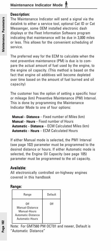
Page
102
Page
102
Page
102
Page
102
Page
102
Mai
nten
ance
Par
amet
ers
Mai
nten
ance
Par
amet
ers
Mai
nten
ance
Par
amet
ers
Mai
nten
ance
Par
amet
ers
Mai
nten
ance
Par
amet
ers
Maintenance Indicator Mode
Description:Description:Description:Description:Description:The Maintenance Indicator will send a signal via thedatalink to either a service tool, optional Cat ID or CatMessenger, some OEM installed electronic dashdisplays or the Fleet Information Software programindicating that maintenance will be due in 3,000 milesor less. This allows for the convenient scheduling ofservice.
The preferred way for the ECM to calculate when thenext preventive maintenance (PM) is due is to com-pare the actual amount of fuel used by the engine, tothe engine oil capacity. (This method is based on thefact that engine oil additives will become depletedover time based on the amount of fuel burned and oilcapacity)
The customer has the option of setting a specific houror mileage (km) Preventive Maintenance (PM) Interval.This is done by programming the MaintenanceIndicator Mode to one of four options:
Manual - Distance Manual - Distance Manual - Distance Manual - Distance Manual - Distance – Fixed number of Miles (km)Manual - HoursManual - HoursManual - HoursManual - HoursManual - Hours – Fixed number of HoursAutomatic - DistanceAutomatic - DistanceAutomatic - DistanceAutomatic - DistanceAutomatic - Distance – ECM Calculated Miles (km)Automatic - HoursAutomatic - HoursAutomatic - HoursAutomatic - HoursAutomatic - Hours – ECM Calculated Hours
If either Manual mode is selected, the PM1 Interval(see page 102) parameter must be programmed to thedesired distance or hours. If either Automatic mode isselected, the Engine Oil Capacity (see page 105)parameter must be programmed to the oil capacity.
Available:Available:Available:Available:Available:All electronically controlled on-highway enginescovered in this handbook
Range:Range:Range:Range:Range:
Note: For GMT560 PM OCT01 and newer, Default is“Automatic Distance”
egnaR tluafeD
ffOecnatsiD-launaM
sruoH-launaMecnatsiD-citamotuA
sruoH-citamotuA
ffO

Page 103Page 103Page 103Page 103Page 103
Advantages:Advantages:Advantages:Advantages:Advantages:This feature allows the customer to take advantage ofthe built-in “maintenance due” reminder feature of theengine electronics while maintaining PM intervalstailored to specific operation. For instance, anextended oil change interval may have been devel-oped with the careful use of Scheduled Oil Sampling.The ECM can then be programmed to the extendedinterval.
Disadvantages:Disadvantages:Disadvantages:Disadvantages:Disadvantages:The customer specified PM interval may not be theoptimum maintenance interval. Maintenance intervalsbased on older technology engines may be too shortand can raise the total cost of ownership.
Recommendations:Recommendations:Recommendations:Recommendations:Recommendations:✔ For most on-highway applications use of the
Automatic-Distance mode is the most effectivemeans to mange preventative maintenance.
Maintenance Param
etersM
aintenance Parameters
Maintenance Param
etersM
aintenance Parameters
Maintenance Param
eters

Page
104
Page
104
Page
104
Page
104
Page
104
Mai
nten
ance
Par
amet
ers
Mai
nten
ance
Par
amet
ers
Mai
nten
ance
Par
amet
ers
Mai
nten
ance
Par
amet
ers
Mai
nten
ance
Par
amet
ers
PM1 Interval
Description:Description:Description:Description:Description:If the Maintenance Indicator Mode (see page 102)parameter has been programmed for either manualmode; Manual-Distance or Manual - Hours, then thePM1 Interval parameter must be programmed to thedesired miles or hours.
Available:Available:Available:Available:Available:All electronically controlled on-highway enginescovered in this handbook
Range:Range:Range:Range:Range:Manual - Distance
Manual - Hours
Advantages:Advantages:Advantages:Advantages:Advantages:By using either manual mode the owner will be notifiedof an upcoming PM interval based on his/her standardinterval.
Disadvantages:Disadvantages:Disadvantages:Disadvantages:Disadvantages:The customer specified PM interval may not be theoptimum maintenance interval. Maintenance intervalsbased on older technology engines may be too shortand can raise the total cost of ownership.
Recommendations:Recommendations:Recommendations:Recommendations:Recommendations:✔ Contact your authorized dealer for help in creating
customized PM intervals.
egnaR taCtluafeDmuminiM mumixaM
seliM0005)mk0508(
seliM00053)mk52365(
seliM00051)mk04142(
enignE
egnaR taCtluafeDmuminiM mumixaM
,21-C,01-C,61-C,51-C
,31C,11C51C
sruoH001 sruoH057 sruoH003
,7C,E62139C sruoH001 sruoH057 sruoH052

Page 105Page 105Page 105Page 105Page 105
Engine Oil Capacity
Description:Description:Description:Description:Description:If the Maintenance Indicator Mode parameter hasbeen programmed for either automatic mode; Auto-matic-Distance or Automatic - Hours, then the EngineOil Capacity parameter must be programmed to theproper amount of oil in the engine.
If a device that increase oil capacity, like a remotemounted bypass filter, is added the ECM could berecommending oil changes more often than warrantedunless the new oil capacity is programmed into theECM.
With the amount of oil programmed, the ECM can thencalculate when the next Preventive Maintenance (PM)is due is to compare the actual amount of fuel used tothe engine oil capacity. (This method is based on thefact that engine oil additives will become depletedover time based on the amount of fuel burned and oilcapacity.)
Available:Available:Available:Available:Available:All electronically controlled on-highway enginescovered in this handbook
Range:Range:Range:Range:Range:
egnaR
tluafeDtaCmuminiM mumixaM
strauQ02)sretiL91(
strauQ06)sretiL75(
noelbateeSegapgniwollof
Maintenance Param
etersM
aintenance Parameters
Maintenance Param
etersM
aintenance Parameters
Maintenance Param
eters

Page
106
Page
106
Page
106
Page
106
Page
106
egnaR tluafeD
9C,7C,E6213 )sretiL13(strauQ33
MG9C,7C,E6213 )sretiL12(strauQ22
,21-C,01-C*31C,11C
)sretiL43(strauQ63
-peeD31C,11CpmuSliOdradnatS
)sretiL04(strauQ24
51C,61-C,51-C )sretiL83(strauQ04
raeR/w51C,61-C,51-CrevaSekarBpmuS
)sretiL83(strauQ04
51C,61-C,51-CpmuStnorF/w
revaSekarB
)sretiL83(**strauQ04
* C11 & C13 shallow oil sump**C-15 & C-16 w/Front Sump BrakeSaver engines shouldbe programmed to 52 quarts (49 liters).
Advantages:Advantages:Advantages:Advantages:Advantages:Additional oil capacity may be added to an engineafter it is installed in the truck and the user cancontinue to effectively use the Maintenance Indicatorby simply adjusting the oil sump capacity parameter.
Disadvantages:Disadvantages:Disadvantages:Disadvantages:Disadvantages:None
Recommendations:Recommendations:Recommendations:Recommendations:Recommendations:✔ In most cases, the factory default value is correct.
This default value would only need to be changedif additional oil capacity was added to the engine.
✔ Caterpillar recommends this correction be madewith the help of an authorized dealer.
Mai
nten
ance
Par
amet
ers
Mai
nten
ance
Par
amet
ers
Mai
nten
ance
Par
amet
ers
Mai
nten
ance
Par
amet
ers
Mai
nten
ance
Par
amet
ers

Page 107Page 107Page 107Page 107Page 107
Trip Parameters/Cat ID(Messenger) Access
Factory Databook Optional
• Fuel Correction Factor ............ ✔Cat ID (Messenger)
Access Parameters• Change Fuel Correction
Factor ..................................... ✔• PM1 Reset ............................. ✔• Fleet Trip Reset .................... ✔• Customer Parameters ......... ✔• State Selection .................... ✔
• Quick Stop Rate ....................... ✔• Theft Deterrent ........................ ✔• Theft Deterrent Password ..... ✔
Trip Parameters
Trip Parameters
Trip Parameters
Trip Parameters
Trip Parameters
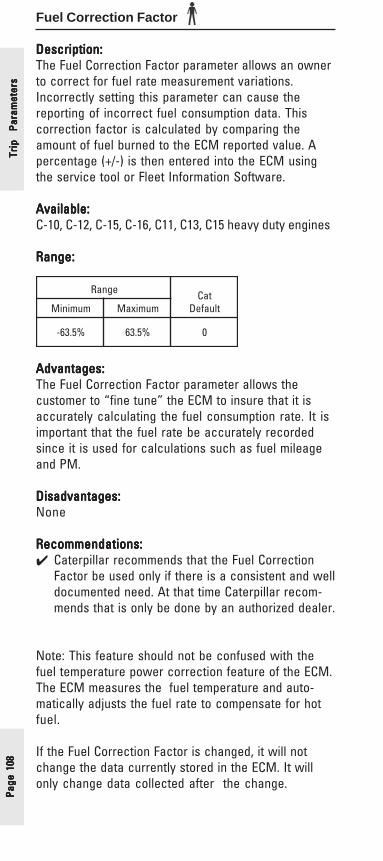
Page
108
Page
108
Page
108
Page
108
Page
108
Trip
Pa
ram
eter
sTr
ip
Para
met
ers
Trip
Pa
ram
eter
sTr
ip
Para
met
ers
Trip
Pa
ram
eter
sFuel Correction Factor
Description:Description:Description:Description:Description:The Fuel Correction Factor parameter allows an ownerto correct for fuel rate measurement variations.Incorrectly setting this parameter can cause thereporting of incorrect fuel consumption data. Thiscorrection factor is calculated by comparing theamount of fuel burned to the ECM reported value. Apercentage (+/-) is then entered into the ECM usingthe service tool or Fleet Information Software.
Available:Available:Available:Available:Available:C-10, C-12, C-15, C-16, C11, C13, C15 heavy duty engines
Range:Range:Range:Range:Range:
Advantages:Advantages:Advantages:Advantages:Advantages:The Fuel Correction Factor parameter allows thecustomer to “fine tune” the ECM to insure that it isaccurately calculating the fuel consumption rate. It isimportant that the fuel rate be accurately recordedsince it is used for calculations such as fuel mileageand PM.
Disadvantages:Disadvantages:Disadvantages:Disadvantages:Disadvantages:None
Recommendations:Recommendations:Recommendations:Recommendations:Recommendations:✔ Caterpillar recommends that the Fuel Correction
Factor be used only if there is a consistent and welldocumented need. At that time Caterpillar recom-mends that is only be done by an authorized dealer.
Note: This feature should not be confused with thefuel temperature power correction feature of the ECM.The ECM measures the fuel temperature and auto-matically adjusts the fuel rate to compensate for hotfuel.
If the Fuel Correction Factor is changed, it will notchange the data currently stored in the ECM. It willonly change data collected after the change.
egnaR taCtluafeDmuminiM mumixaM
%5.36- %5.36 0

Page 109Page 109Page 109Page 109Page 109
Example:Example:Example:Example:Example:
New FCF = New Fuel Correction FactorOld FCF = Old Fuel Correction Factor (the value currently
programmed in the Fuel Correction Factorparameter)
ECM = Fuel Mileage as calculated by the ECMTank = Actual Fuel Mileage as calculated using pump
receipts
The -3.8748 is rounded off the nearest 0.5%.
The New Fuel Correction Factor is -4.0%
Trip Parameters
Trip Parameters
Trip Parameters
Trip Parameters
Trip Parameters

Page
110
Page
110
Page
110
Page
110
Page
110
Trip
Pa
ram
eter
sTr
ip
Para
met
ers
Trip
Pa
ram
eter
sTr
ip
Para
met
ers
Trip
Pa
ram
eter
sDash Display Access Parameter
Change Fuel Correction Factor
Description:Description:Description:Description:Description:The Change Fuel Correction Factor parameter allowsthe Fuel Correction Factor parameter to be pro-grammed from the Caterpillar Driver InformationDisplay (Cat ID) or Cat Messenger. A properly installedCat ID or Cat Messenger is required.
Options are:NoNoNoNoNo - Can not change Fuel Correction Factor from
Cat ID or Cat MessengerYesYesYesYesYes - May change Fuel Correction Factor from Cat ID
or Cat Messenger
Available:Available:Available:Available:Available:C-10, C-12, C-15, C-16, C11, C13, C15 heavy duty engines
Range:Range:Range:Range:Range:
Advantages:Advantages:Advantages:Advantages:Advantages:An owner-operator may want driver access to thisparameter, a fleet operation may not.
Disadvantages:Disadvantages:Disadvantages:Disadvantages:Disadvantages:Unnecessary changing of the Fuel Correction Factorcould adversely affect the data stored in the ECM.
Recommendations:Recommendations:Recommendations:Recommendations:Recommendations:✔ Set the Dash Display Access to Change the Fuel
Correction parameter to No. This will eliminate thepossibility of inadvertent changing of the FuelCorrection Factor parameter.
✔ Contact your authorized dealer for help in program-ming the Fuel Correction Factor.
egnaR tluafeD
seYoN oN

Page 111Page 111Page 111Page 111Page 111
Dash Display Access ParameterPM1 Reset
Description:Description:Description:Description:Description:This parameter allows the reset of the PM1 Mainte-nance via the Caterpillar Driver Information Display(Cat ID) or Cat Messenger. A properly installed Cat IDor Cat Messenger is required and the MaintenanceIndicator Mode parameter must be programmed toeither of the Manual or Automatic Modes.
Options are:NoNoNoNoNo - Can not reset Maintenance Indicator from
Cat ID or Cat MessengerYesYesYesYesYes - May reset Maintenance Indicator from Cat ID or
Cat Messenger
Available:Available:Available:Available:Available:All electronically-controlled engines covered in thishandbook
Range:Range:Range:Range:Range:
Advantages:Advantages:Advantages:Advantages:Advantages:For those who have a Caterpillar Driver InformationDisplay or Cat Messenger and are using one of theMaintenance Indicator Modes this feature allows theresetting of the Maintenance Indicator without aservice tool.
Disadvantages:Disadvantages:Disadvantages:Disadvantages:Disadvantages:If the PM is accidently reset from the Dash Display, theoil change interval could be exceeded.
Recommendations:Recommendations:Recommendations:Recommendations:Recommendations:✔ Program this parameter to No unless this feature is
desired by the driver or fleet owner.
✔ This programmable feature is application depen-dant and should be programmed based on cus-tomer specific requirements.
Trip Parameters
Trip Parameters
Trip Parameters
Trip Parameters
Trip Parameters
egnaR tluafeD
seYoN oN
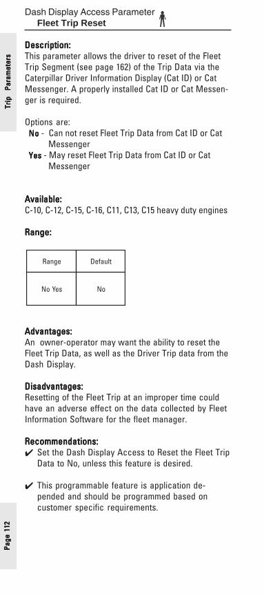
Page
112
Page
112
Page
112
Page
112
Page
112
Trip
Pa
ram
eter
sTr
ip
Para
met
ers
Trip
Pa
ram
eter
sTr
ip
Para
met
ers
Trip
Pa
ram
eter
sDash Display Access Parameter
Fleet Trip Reset
Description:Description:Description:Description:Description:This parameter allows the driver to reset of the FleetTrip Segment (see page 162) of the Trip Data via theCaterpillar Driver Information Display (Cat ID) or CatMessenger. A properly installed Cat ID or Cat Messen-ger is required.
Options are:NoNoNoNoNo - Can not reset Fleet Trip Data from Cat ID or Cat
MessengerYesYesYesYesYes - May reset Fleet Trip Data from Cat ID or Cat Messenger
Available:Available:Available:Available:Available:C-10, C-12, C-15, C-16, C11, C13, C15 heavy duty engines
Range:Range:Range:Range:Range:
Advantages:Advantages:Advantages:Advantages:Advantages:An owner-operator may want the ability to reset theFleet Trip Data, as well as the Driver Trip data from theDash Display.
Disadvantages:Disadvantages:Disadvantages:Disadvantages:Disadvantages:Resetting of the Fleet Trip at an improper time couldhave an adverse effect on the data collected by FleetInformation Software for the fleet manager.
Recommendations:Recommendations:Recommendations:Recommendations:Recommendations:✔ Set the Dash Display Access to Reset the Fleet Trip
Data to No, unless this feature is desired.
✔ This programmable feature is application de-pended and should be programmed based oncustomer specific requirements.
egnaR tluafeD
seYoN oN

Page 113Page 113Page 113Page 113Page 113
Dash Display Access ParameterCustomer Parameters
Description:Description:Description:Description:Description:The Dash Display Access Parameter - CustomerParameters is a medium duty feature only. It allowsthe operator to change the following customerprogrammable parameters via a Caterpillar dashdisplay:
• Soft Cruise ControlSoft Cruise ControlSoft Cruise ControlSoft Cruise ControlSoft Cruise Control• Fast Idle RPM #1Fast Idle RPM #1Fast Idle RPM #1Fast Idle RPM #1Fast Idle RPM #1• Fast Idle RPM #2Fast Idle RPM #2Fast Idle RPM #2Fast Idle RPM #2Fast Idle RPM #2• Low Idle Engine RPMLow Idle Engine RPMLow Idle Engine RPMLow Idle Engine RPMLow Idle Engine RPM
Available:Available:Available:Available:Available:3126E, C7, C9 medium duty engines
Range:Range:Range:Range:Range:
Advantages:Advantages:Advantages:Advantages:Advantages:Programming this parameter to Yes allows the operatorthe ability to change the customer parameters listedabove easily from the cab of the truck.
Disadvantages:Disadvantages:Disadvantages:Disadvantages:Disadvantages:None
sevitanretlA tluafeD
seY oN
Trip Parameters
Trip Parameters
Trip Parameters
Trip Parameters
Trip Parameters
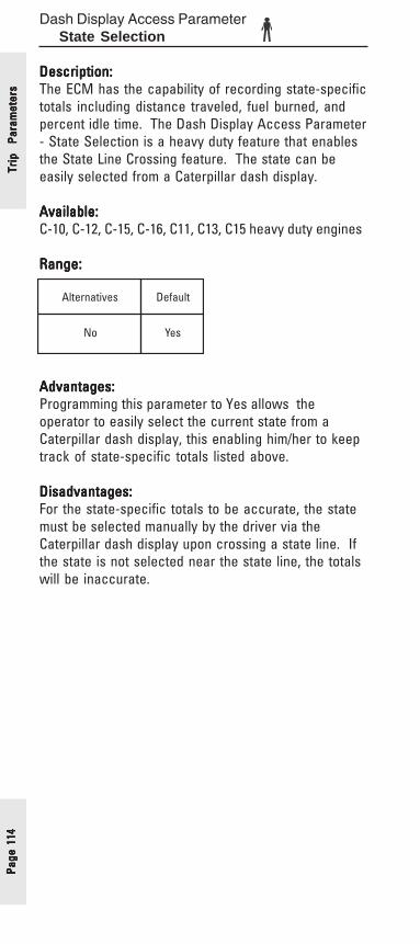
Page
114
Page
114
Page
114
Page
114
Page
114
Trip
Pa
ram
eter
sTr
ip
Para
met
ers
Trip
Pa
ram
eter
sTr
ip
Para
met
ers
Trip
Pa
ram
eter
sDash Display Access Parameter
State Selection
Description:Description:Description:Description:Description:The ECM has the capability of recording state-specifictotals including distance traveled, fuel burned, andpercent idle time. The Dash Display Access Parameter- State Selection is a heavy duty feature that enablesthe State Line Crossing feature. The state can beeasily selected from a Caterpillar dash display.
Available:Available:Available:Available:Available:C-10, C-12, C-15, C-16, C11, C13, C15 heavy duty engines
Range:Range:Range:Range:Range:
Advantages:Advantages:Advantages:Advantages:Advantages:Programming this parameter to Yes allows theoperator to easily select the current state from aCaterpillar dash display, this enabling him/her to keeptrack of state-specific totals listed above.
Disadvantages:Disadvantages:Disadvantages:Disadvantages:Disadvantages:For the state-specific totals to be accurate, the statemust be selected manually by the driver via theCaterpillar dash display upon crossing a state line. Ifthe state is not selected near the state line, the totalswill be inaccurate.
sevitanretlA tluafeD
oN seY

Page 115Page 115Page 115Page 115Page 115
Quick Stop Rate
Description:Description:Description:Description:Description:The Quick Stop Rate parameter value is the thresholdat which a Quick Stop Event (Date, time and snapshot)will be logged in the ECM memory. The ECM monitorsthe rate of change of vehicle speed. If the rate ofchange is greater than or equal to the value pro-grammed into the Quick Stop Rate parameter a QuickStop Event will be logged. Quick Stop Rate value isapplication sensitive, light loads may require a highervalue and heavy loads a smaller value. If the QuickStop Rate parameter is programmed to 0 (zero) thefeature is disabled and no Quick Stop Events will belogged.
Available:Available:Available:Available:Available:All electronically controlled on-highway enginescovered in this handbook
Range:Range:Range:Range:Range:
Advantages:Advantages:Advantages:Advantages:Advantages:All ECM recorded vehicle and engine conditions canbe replayed for 44 seconds before and 15 secondsafter the Quick Stop Event. This data may providevaluable information on drivetrain component wear.
Disadvantages:Disadvantages:Disadvantages:Disadvantages:Disadvantages:None
Recommendations:Recommendations:Recommendations:Recommendations:Recommendations:✔ Program a value of 7 MPH/Sec as a starting point.
enignEegnaR taC
tluafeDmuminiM mumixaM
9C,7C,E6213 ceS/HPM0)ceS/h/mk0(
ceS/HPM821)ceS/h/mk502(
0
-C,21-C,01-C,11C,61-C,51
51C,31C
ceS/HPM0)ceS/h/mk0(
ceS/HPM51)ceS/h/mk42(
0
Trip Parameters
Trip Parameters
Trip Parameters
Trip Parameters
Trip Parameters

Page
116
Page
116
Page
116
Page
116
Page
116
Theft Deterrent
Description:Description:Description:Description:Description:When used with the Theft Deterrent Passwordparameter (see page 117), the Theft Deterrent systemprevents the engine from starting unless the passwordhas been entered via the Caterpillar Driver InformationDisplay (Cat ID) or Cat Messenger.
Before the operator can use the Theft Deterrentfeature of the Cat ID or Cat Messenger, the systemmust be turned On. To turn the Theft Deterrent systemOn, a service tool must be used to program the TheftDeterrent parameter to Yes.
NoNoNoNoNo -Theft Deterrent capability turned Off
YesYesYesYesYes -Theft Deterrent capability turned On
Auto Enable Auto Enable Auto Enable Auto Enable Auto Enable -Operator must must must must must enter a password to start, regardlessof how engine was shut-off
Once the Theft Deterrent parameter has been turnedOn, the operator must enter the password before before before before before theengine shuts off or the key is turned to the off position.The engine will not restart without reentering thepassword. For further detail on Cat ID or Cat Messen-ger operation, including the Theft Deterrent featurerefer to the Operation and Maintenance Manual.
Available:Available:Available:Available:Available:All electronically controlled on-highway enginescovered in this handbook
Range:Range:Range:Range:Range:
Advantages:Advantages:Advantages:Advantages:Advantages:The Theft Deterrent can be an effective method tocontrol unauthorized operation of the vehicle.
Disadvantages:Disadvantages:Disadvantages:Disadvantages:Disadvantages:If the password is forgotten, the truck will be out ofservice. The password can be obtained using aservice tool.
Recommendations:Recommendations:Recommendations:Recommendations:Recommendations:✔ Caterpillar recommends the use of the Theft
Deterrent feature.
sevitanretlA tluafeD
elbanE-otuA,seY oN
Trip
Pa
ram
eter
sTr
ip
Para
met
ers
Trip
Pa
ram
eter
sTr
ip
Para
met
ers
Trip
Pa
ram
eter
s

Page 117Page 117Page 117Page 117Page 117
Theft Deterrent Password
Description:Description:Description:Description:Description:The Theft Deterrent password is required if the TheftDeterrent parameter (see previous page) is pro-grammed to Yes. This password is then required torestart the engine if the Theft Deterrent feature hasbeen enabled before the engine was shutdown. If theTheft Deterrent Password is lost or forgotten a servicetool is required to start the engine.
Available:Available:Available:Available:Available:All electronically controlled on-highway enginescovered in this handbook
Range:Range:Range:Range:Range:
Advantages:Advantages:Advantages:Advantages:Advantages:The Theft Deterrent can be an effective method tocontrol unauthorized operation of the vehicle.
Disadvantages:Disadvantages:Disadvantages:Disadvantages:Disadvantages:If the password is forgotten, the truck will be out ofservice. The password can be obtained using aservice tool.
Recommendations:Recommendations:Recommendations:Recommendations:Recommendations:✔ Caterpillar recommends using the Theft Deterrent
System.
✔ With a choice of all alphanumeric characters apassword can be selected that is easily remem-bered.
egnaR tluafeD
ruoFAsretcarahC
,Zurht9urht0
0000)soreZllA(
Trip Parameters
Trip Parameters
Trip Parameters
Trip Parameters
Trip Parameters
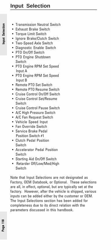
Page
118
Page
118
Page
118
Page
118
Page
118
Input Selection
• Transmission Neutral Switch• Exhaust Brake Switch• Torque Limit Switch• Ignore Brake/Clutch Switch• Two-Speed Axle Switch• Diagnostic Enable Switch• PTO On/Off Switch• PTO Engine Shutdown Switch• PTO Engine RPM Set Speed Input A• PTO Engine RPM Set Speed Input B• Remote PTO Set Switch• Remote PTO Resume Switch• Cruise Control On/Off Switch• Cruise Control Set/Resume Switch• Cruise Control Pause Switch• A/C High Pressure Switch• A/C Fan Request Switch• Vehicle Speed Input• Fan Override Switch• Service Brake Pedal Position Switch #1• Clutch Pedal Position Switch• Accelerator Pedal Position Switch• Starting Aid On/Off Switch• Retarder Off/Low/Med/High Switch
Note that Input Selections are not designated asFactory, OEM Databook, or Optional. These selectionsare all, in effect, optional, but are typically set at thefactory. However, after the vehicle is shipped, variousinputs can be added either by the customer or OEM.The Input Selections section has been added forcompleteness due to its direct relation with theparameters discussed in this handbook.
Inpu
t Se
lect
ion
Inpu
t Se
lect
ion
Inpu
t Se
lect
ion
Inpu
t Se
lect
ion
Inpu
t Se
lect
ion
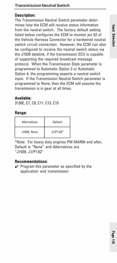
Page 119Page 119Page 119Page 119Page 119
Transmission Neutral Switch
Description:Description:Description:Description:Description:The Transmission Neutral Switch parameter deter-mines how the ECM will receive status informationfrom the neutral switch. The factory default settinglisted below configures the ECM to monitor pin 62 ofthe Vehicle Harness Connector for a hardwired neutralswitch circuit connection. However, the ECM can alsobe configured to receive the neutral switch status viathe J1939 datalink, if the transmission ECU is capableof supporting the required broadcast messageprotocol. When the Transmission Style parameter isprogrammed to Automatic Option 3 or AutomaticOption 4, the programming expects a neutral switchinput. If the Transmission Neutral Switch parameter isprogrammed to None, then the ECM will assume thetransmission is in gear at all times.
Available:Available:Available:Available:Available:3126E, C7, C9, C11, C13, C15
Range:Range:Range:Range:Range:
*Note: For heavy duty engines PM MAR04 and after,Default is “None” and Alternatives are“J1939, J1/P1:62”
Recommendations:Recommendations:Recommendations:Recommendations:Recommendations:✔ Program this parameter as specified by the
application and transmission
sevitanretlA tluafeD
enoN,9391J *26:1P/1J
Input SelectionInput SelectionInput SelectionInput SelectionInput Selection

Page
120
Page
120
Page
120
Page
120
Page
120
Exhaust Brake Switch
Description:Description:Description:Description:Description:The Exhaust Brake Switch parameter is used todetermine the nature of the Exhaust Brake Switchconnection to the ECM. See recommendations belowfor appropriate parameter programming based onswitch connection.
Available:Available:Available:Available:Available:3126E, C7, C9 medium-duty engines
Range:Range:Range:Range:Range:
Recommendations:Recommendations:Recommendations:Recommendations:Recommendations:✔ If the Exhaust Brake Switch is installed in the ECM
Exhaust Brake Output circuit to disable the brakeby opening the output circuit, the Exhaust BrakeSwitch parameter should be programmed to None.
✔ If the Exhaust Brake Switch is connected to thededicated ECM Exhaust Brake Switch Input, thenthe Exhaust Brake Switch parameter should beprogrammed to one of the Alternatives.
sevitanretlA tluafeD
,rellortnoCydoB9391J,61:1P/1J9391J,rellortnoCbaC9391J
retsulCtnemurtsnI
enoN
Inpu
t Se
lect
ion
Inpu
t Se
lect
ion
Inpu
t Se
lect
ion
Inpu
t Se
lect
ion
Inpu
t Se
lect
ion

Page 121Page 121Page 121Page 121Page 121
Torque Limit Switch
Description:Description:Description:Description:Description:The Torque Limit Switch parameter is programmed toselect the input connection for the programmabletorque limit. The Torque Limit Switch should only beused for temporary PTO equipment protection, andshould not be used continuously. Please refer to theTorque Limit parameter, discussed in detail on page59.
Available:Available:Available:Available:Available:All electronically programmable on-highway enginescovered in this handbook
Range:Range:Range:Range:Range:
*Note: J1/P1:23 only applicable for 3126E, C7, C9medium-duty engines
Advantages:Advantages:Advantages:Advantages:Advantages:Programming this parameter allows the operator theability to make use of the Torque Limit parameter’sability to limit torque in PTO applications and protectPTO equipment when necessary.
Disadvantages:Disadvantages:Disadvantages:Disadvantages:Disadvantages:None
Recommendations:Recommendations:Recommendations:Recommendations:Recommendations:✔ The Torque Limit Switch should only be used to
temporarily protect PTO equipment and should notbe used continuously.
sevitanretlA tluafeD
*7:1P/1J,32:1P/1J enoN
Input SelectionInput SelectionInput SelectionInput SelectionInput Selection
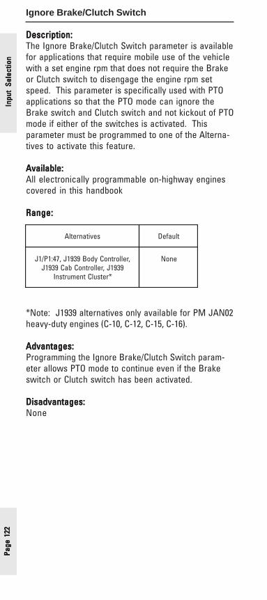
Page
122
Page
122
Page
122
Page
122
Page
122
Ignore Brake/Clutch Switch
Description:Description:Description:Description:Description:The Ignore Brake/Clutch Switch parameter is availablefor applications that require mobile use of the vehiclewith a set engine rpm that does not require the Brakeor Clutch switch to disengage the engine rpm setspeed. This parameter is specifically used with PTOapplications so that the PTO mode can ignore theBrake switch and Clutch switch and not kickout of PTOmode if either of the switches is activated. Thisparameter must be programmed to one of the Alterna-tives to activate this feature.
Available:Available:Available:Available:Available:All electronically programmable on-highway enginescovered in this handbook
Range:Range:Range:Range:Range:
*Note: J1939 alternatives only available for PM JAN02heavy-duty engines (C-10, C-12, C-15, C-16).
Advantages:Advantages:Advantages:Advantages:Advantages:Programming the Ignore Brake/Clutch Switch param-eter allows PTO mode to continue even if the Brakeswitch or Clutch switch has been activated.
Disadvantages:Disadvantages:Disadvantages:Disadvantages:Disadvantages:None
sevitanretlA tluafeD
,rellortnoCydoB9391J,74:1P/1J9391J,rellortnoCbaC9391J
*retsulCtnemurtsnI
enoN
Inpu
t Se
lect
ion
Inpu
t Se
lect
ion
Inpu
t Se
lect
ion
Inpu
t Se
lect
ion
Inpu
t Se
lect
ion
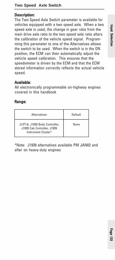
Page 123Page 123Page 123Page 123Page 123
Two Speed Axle Switch
Description:Description:Description:Description:Description:The Two Speed Axle Switch parameter is available forvehicles equipped with a two speed axle. When a twospeed axle is used, the change in gear ratio from themain drive axle ratio to the two speed axle ratio altersthe calibration of the vehicle speed signal. Program-ming this parameter to one of the Alternatives allowsthe switch to be used. When the switch is in the ONposition, the ECM can then automatically adjust thevehicle speed calibration. This ensures that thespeedometer is driven by the ECM and that the ECMstored information correctly reflects the actual vehiclespeed.
Available:Available:Available:Available:Available:All electronically programmable on-highway enginescovered in this handbook
Range:Range:Range:Range:Range:
*Note: J1939 alternatives available PM JAN02 andafter on heavy-duty engines
sevitanretlA tluafeD
,rellortnoCydoB9391J,6:1P/1J9391J,rellortnoCbaC9391J
*retsulCtnemurtsnI
enoN
Input SelectionInput SelectionInput SelectionInput SelectionInput Selection

Page
124
Page
124
Page
124
Page
124
Page
124
Diagnostic Enable Switch
Description:Description:Description:Description:Description:The Diagnostic Enable Switch can be used by anoperator or technician to prompt for diagnostic flashcodes. The input can be programmed to be hard wiredto the ECM or connected via the J1939 data link.
Available:Available:Available:Available:Available:All electronically programmable on-highway enginescovered in this handbook
Range:Range:Range:Range:Range:
*Note: J1939 alternatives NOT available on PM OCT01heavy-duty engines (C-10, C-12, C-15, C-16)
sevitanretlA tluafeD
,rellortnoCydoB9391J,64:1P/1J9391J,rellortnoCbaC9391J
*retsulCtnemurtsnI
enoN
Inpu
t Se
lect
ion
Inpu
t Se
lect
ion
Inpu
t Se
lect
ion
Inpu
t Se
lect
ion
Inpu
t Se
lect
ion

Page 125Page 125Page 125Page 125Page 125
PTO On/Off Switch
Description:Description:Description:Description:Description:The PTO On/Off Switch parameter is available tospecify the PTO On/Off Switch connection to the ECM.The switch itself can only be used when the PTOConfiguration parameter is set to Cab Switches,Remote Switches, or Remote Throttle.
Available:Available:Available:Available:Available:C7, C9 medium-duty engines (PM MAR04 and after)
Range:Range:Range:Range:Range:
Advantages:Advantages:Advantages:Advantages:Advantages:When programmed properly, this parameter allows theuse of the PTO On/Off Switch to control PTO operation.
Disadvantages:Disadvantages:Disadvantages:Disadvantages:Disadvantages:None
Recommendations:Recommendations:Recommendations:Recommendations:Recommendations:✔ If J1939 sources are not available on the vehicle,
make sure that the PTO On/Off Switch parameter isnot programmed to one of the J1939 Alternatives.Even if the PTO Configuration parameter is set toOff, this will result in a diagnostic code event
sevitanretlA tluafeD
baC9391J,rellortnoCydoB9391JtnemurtsnI9391J,rellortnoC
retsulC
65:1P/1J
Input SelectionInput SelectionInput SelectionInput SelectionInput Selection

Page
126
Page
126
Page
126
Page
126
Page
126
PTO Engine Shutdown Switch
Description:Description:Description:Description:Description:The PTO Engine Shutdown Switch can be used to shutthe engine down while in PTO mode with no vehiclespeed present. This is an emergency feature, andtherefore the ECM will log an Emergency PTO Shut-down Event.
Available:Available:Available:Available:Available:3126E, C7, C9 medium-duty engines
Range:Range:Range:Range:Range:
Advantages:Advantages:Advantages:Advantages:Advantages:The PTO Engine Shutdown Switch parameter allows anemergency engine shutdown while in PTO modeprovided there is no vehicle speed present.
Disadvantages:Disadvantages:Disadvantages:Disadvantages:Disadvantages:None
sevitanretlA tluafeD
7:1P/1J,32:1P/1J enoN
Inpu
t Se
lect
ion
Inpu
t Se
lect
ion
Inpu
t Se
lect
ion
Inpu
t Se
lect
ion
Inpu
t Se
lect
ion
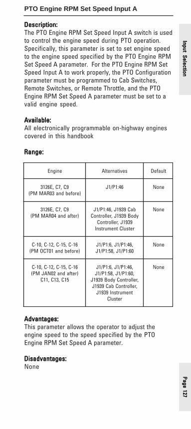
Page 127Page 127Page 127Page 127Page 127
PTO Engine RPM Set Speed Input A
Description:Description:Description:Description:Description:The PTO Engine RPM Set Speed Input A switch is usedto control the engine speed during PTO operation.Specifically, this parameter is set to set engine speedto the engine speed specified by the PTO Engine RPMSet Speed A parameter. For the PTO Engine RPM SetSpeed Input A to work properly, the PTO Configurationparameter must be programmed to Cab Switches,Remote Switches, or Remote Throttle, and the PTOEngine RPM Set Speed A parameter must be set to avalid engine speed.
Available:Available:Available:Available:Available:All electronically programmable on-highway enginescovered in this handbook
Range:Range:Range:Range:Range:
Advantages:Advantages:Advantages:Advantages:Advantages:This parameter allows the operator to adjust theengine speed to the speed specified by the PTOEngine RPM Set Speed A parameter.
Disadvantages:Disadvantages:Disadvantages:Disadvantages:Disadvantages:None
enignE sevitanretlA tluafeD
9C,7C,E6213)erofebdna30RAMMP(
64:1P/1J enoN
9C,7C,E6213)retfadna40RAMMP(
baC9391J,64:1P/1JydoB9391J,rellortnoC
9391J,rellortnoCretsulCtnemurtsnI
enoN
61-C,51-C,21-C,01-C)erofebdna10TCOMP(
,64:1P/1J,6:1P/1J06:1P/1J,85:1P/1J
enoN
61-C,51-C,21-C,01-C)retfadna20NAJMP(
51C,31C,11C
,64:1P/1J,6:1P/1J,06:1P/1J,85:1P/1J
,rellortnoCydoB9391J,rellortnoCbaC9391J
tnemurtsnI9391JretsulC
enoN
Input SelectionInput SelectionInput SelectionInput SelectionInput Selection
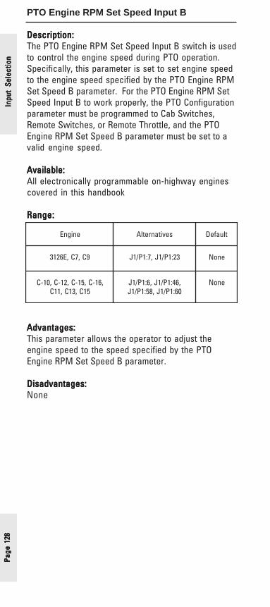
Page
128
Page
128
Page
128
Page
128
Page
128
PTO Engine RPM Set Speed Input B
Description:Description:Description:Description:Description:The PTO Engine RPM Set Speed Input B switch is usedto control the engine speed during PTO operation.Specifically, this parameter is set to set engine speedto the engine speed specified by the PTO Engine RPMSet Speed B parameter. For the PTO Engine RPM SetSpeed Input B to work properly, the PTO Configurationparameter must be programmed to Cab Switches,Remote Switches, or Remote Throttle, and the PTOEngine RPM Set Speed B parameter must be set to avalid engine speed.
Available:Available:Available:Available:Available:All electronically programmable on-highway enginescovered in this handbook
Range:Range:Range:Range:Range:
Advantages:Advantages:Advantages:Advantages:Advantages:This parameter allows the operator to adjust theengine speed to the speed specified by the PTOEngine RPM Set Speed B parameter.
Disadvantages:Disadvantages:Disadvantages:Disadvantages:Disadvantages:None
enignE sevitanretlA tluafeD
9C,7C,E6213 32:1P/1J,7:1P/1J enoN
,61-C,51-C,21-C,01-C51C,31C,11C
,64:1P/1J,6:1P/1J06:1P/1J,85:1P/1J
enoN
Inpu
t Se
lect
ion
Inpu
t Se
lect
ion
Inpu
t Se
lect
ion
Inpu
t Se
lect
ion
Inpu
t Se
lect
ion
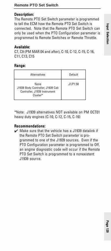
Page 129Page 129Page 129Page 129Page 129
Remote PTO Set Switch
Description:Description:Description:Description:Description:The Remote PTO Set Switch parameter is programmedto tell the ECM how the Remote PTO Set Switch isconnected. Note that the Remote PTO Set Switch canonly be used when the PTO Configuration parameter isprogrammed to Remote Switches or Remote Throttle.
Available:Available:Available:Available:Available:C7, C9 (PM MAR 04 and after), C-10, C-12, C-15, C-16,C11, C13, C15
Range:Range:Range:Range:Range:
*Note: J1939 alternatives NOT available on PM OCT01heavy duty engines (C-10, C-12, C-15, C-16)
Recommendations:Recommendations:Recommendations:Recommendations:Recommendations:✔ Make sure that the vehicle has a J1939 datalink if
the Remote PTO Set Switch parameter is pro-grammed to one of the J1939 sources. Even if thePTO Configuration parameter is programmed to Off,an engine diagnostic code will occur if the RemotePTO Set Switch is programmed to a nonexistentJ1939 source.
sevitanretlA tluafeD
enoNbaC9391J,rellortnoCydoB9391J
tnemurtsnI9391J,rellortnoC*retsulC
85:1P/1J
Input SelectionInput SelectionInput SelectionInput SelectionInput Selection

Page
130
Page
130
Page
130
Page
130
Page
130
Remote PTO Resume Switch
Description:Description:Description:Description:Description:The Remote PTO Resume Switch parameter is pro-grammed to tell the ECM how the Remote PTO ResumeSwitch is connected. Note that the Remote PTOResume Switch can only be used when the PTOConfiguration parameter is programmed to RemoteSwitches or Remote Throttle.
Available:Available:Available:Available:Available:C7, C9 (PM MAR 04 and after), C-10, C-12, C-15, C-16,C11, C13, C15
Range:Range:Range:Range:Range:
*Note: J1939 alternatives NOT available on PM OCT01heavy duty engines (C-10, C-12, C-15, C-16)
Recommendations:Recommendations:Recommendations:Recommendations:Recommendations:✔ Make sure that the vehicle has a J1939 datalink if
the Remote PTO Set Switch parameter is pro-grammed to one of the J1939 sources. Even if thePTO Configuration parameter is programmed to Off,an engine diagnostic code will occur if the RemotePTO Set Switch is programmed to a nonexistentJ1939 source.
sevitanretlA tluafeD
enoNbaC9391J,rellortnoCydoB9391J
tnemurtsnI9391J,rellortnoC*retsulC
06:1P/1J
Inpu
t Se
lect
ion
Inpu
t Se
lect
ion
Inpu
t Se
lect
ion
Inpu
t Se
lect
ion
Inpu
t Se
lect
ion

Page 131Page 131Page 131Page 131Page 131
Cruise Control On/Off Switch
Description:Description:Description:Description:Description:The Cruise Control On/Off Switch input parameteridentifies the Cruise Control On/Off Switch connectionto the ECM. The switch itself is used to enable cruisecontrol when the vehicle is moving, or to controlengine idle rpm when the vehicle is stationary.
Available:Available:Available:Available:Available:All electronically programmable on-highway enginescovered in this handbook
Range:Range:Range:Range:Range:
*Note: J1939 alternatives NOT available on PM OCT01heavy duty engines (C-10, C-12, C-15, C-16)
Recommendations:Recommendations:Recommendations:Recommendations:Recommendations:✔ Make sure that the J1939 data link is available if
this parameter is programmed to one of the J1939source Alternatives. Failure to do so will result in adiagnostic code.
sevitanretlA tluafeD
baC9391J,rellortnoCydoB9391JtnemurtsnI9391J,rellortnoC
*retsulC
95:1P/1J
Input SelectionInput SelectionInput SelectionInput SelectionInput Selection

Page
132
Page
132
Page
132
Page
132
Page
132
Cruise Control Set/Resume Switch
Description:Description:Description:Description:Description:The Cruise Control Set/Resume Switch parameter isprogrammed to identify the Cruise Control Set/ResumeSwitch connection to the ECM. The switch itself isused in conjunction with the Cruise Control On/OffSwitch to control cruise control operation when thevehicle is moving, to adjust engine idle rpm when thevehicle is stationary, to adjust engine rpm when thePTO Configuration parameter is set to Cab Switches,and to enable diagnostic flash codes on the CheckEngine Lamp.
Available:Available:Available:Available:Available:All electronically programmable on-highway enginescovered in this handbook
Range:Range:Range:Range:Range:
*Note: J1939 alternatives NOT available on PM OCT01heavy duty engines (C-10, C-12, C-15, C-16)
Recommendations:Recommendations:Recommendations:Recommendations:Recommendations:✔ Make sure that the J1939 data link is available if
this parameter is programmed to one of the J1939source Alternatives. Failure to do so will result in adiagnostic code.
enignE sevitanretlA tluafeD
9C,7C,E6213)retfadna40RAMMP(
,rellortnoCydoB9391J,rellortnoCbaC9391J
tnemurtsnI9391J*retsulC
53:1P/1J33&
9C,7C,E6213)erofebdna30RAMMP(
,61-C,51-C,21-C,01-C51C,31C,11C
,rellortnoCydoB9391J,rellortnoCbaC9391J
tnemurtsnI9391J*retsulC
53:1P/1J44&
Inpu
t Se
lect
ion
Inpu
t Se
lect
ion
Inpu
t Se
lect
ion
Inpu
t Se
lect
ion
Inpu
t Se
lect
ion

Page 133Page 133Page 133Page 133Page 133
Cruise Control Pause Switch
Description:Description:Description:Description:Description:The Cruise Control Pause Switch parameter is pro-grammed to identify the Cruise Control Pause Switchconnection to the ECM. If this parameter is pro-grammed to J1939 Body Controller, Instrument Cluster,or Cab Controller, the Cruise Control Pause Switch willact like the service brake or clutch switch by causingthe PTO mode to kickout. If in the On position, theswitch will prevent the engine from entering PTOmode, and there is no programmable parameter forignoring this switch.
Available:Available:Available:Available:Available:3126E, C7, C9C-10, C-12, C-15, C-16 (PM JAN02 and after)C11, C13, C15
Range:Range:Range:Range:Range:
Recommendations:Recommendations:Recommendations:Recommendations:Recommendations:✔ Make sure that the vehicle is equipped with a
J1939 data link if programming this parameter toone of the J1939 source Alternatives. Failure to doso will generate a diagnostic code.
sevitanretlA tluafeD
baC9391J,rellortnoCydoB9391JtnemurtsnI9391J,rellortnoC
retsulC
enoN
Input SelectionInput SelectionInput SelectionInput SelectionInput Selection
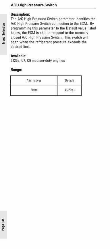
Page
134
Page
134
Page
134
Page
134
Page
134
A/C High Pressure Switch
Description:Description:Description:Description:Description:The A/C High Pressure Switch parameter identifies theA/C High Pressure Switch connection to the ECM. Byprogramming this parameter to the Default value listedbelow, the ECM is able to respond to the normallyclosed A/C High Pressure Switch. This switch willopen when the refrigerant pressure exceeds thedesired limit.
Available:Available:Available:Available:Available:3126E, C7, C9 medium-duty engines
Range:Range:Range:Range:Range:
sevitanretlA tluafeD
enoN 14:1P/1J
Inpu
t Se
lect
ion
Inpu
t Se
lect
ion
Inpu
t Se
lect
ion
Inpu
t Se
lect
ion
Inpu
t Se
lect
ion
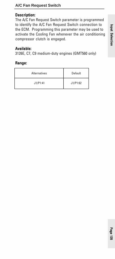
Page 135Page 135Page 135Page 135Page 135
A/C Fan Request Switch
Description:Description:Description:Description:Description:The A/C Fan Request Switch parameter is programmedto identify the A/C Fan Request Switch connection tothe ECM. Programming this parameter may be used toactivate the Cooling Fan whenever the air conditioningcompressor clutch is engaged.
Available:Available:Available:Available:Available:3126E, C7, C9 medium-duty engines (GMT560 only)
Range:Range:Range:Range:Range:
sevitanretlA tluafeD
14:1P/1J 26:1P/1J
Input SelectionInput SelectionInput SelectionInput SelectionInput Selection

Page
136
Page
136
Page
136
Page
136
Page
136
Vehicle Speed Input
Description:Description:Description:Description:Description:The ECM has an input circuit that can be used toconnect a hardwired vehicle speed sensor producinga differential input signal, or a single ended signalfrom an electronic control. To make use of thisfeature, the Vehicle Speed Input parameter must beprogrammed to the Default option listed below. TheECM can also be configured to receive vehicle speedinformation from an Electronic Transmission ControlUnit via the J1939 datalink, provided that the transmis-sion is capable of supporting the J1939 ETC1 Broad-cast Message protocol. Note that if this method is tobe used, the J1939 Trans option must be selected aswell.
Available:Available:Available:Available:Available:All electronically programmable on-highway enginescovered in this handbook
Range:Range:Range:Range:Range:
*Note: J1939 ABS alternative not available on PMOCT01 heavy-duty engines (C-10, C-12, C-15, C-16)**Note: Default value is “None” for C7 and C9medium-duty engines (PM MAR04 and after)
sevitanretlA tluafeD
snarT9391J*SBA9391J
**33&23:1P/1J
Inpu
t Se
lect
ion
Inpu
t Se
lect
ion
Inpu
t Se
lect
ion
Inpu
t Se
lect
ion
Inpu
t Se
lect
ion

Page 137Page 137Page 137Page 137Page 137
Fan Override Switch
Description:Description:Description:Description:Description:The Fan Override Switch parameter is programmed toidentify the Fan Override Switch connection to theECM. This parameter can be programmed to one ofthe available hard wired options or J1939 datalinksource inputs. The switch itself allows the operator toturn on the cooling fan at any time, resulting inimproved retarding/braking and engine cooling.
Available:Available:Available:Available:Available:All electronically programmable on-highway enginescovered in this handbook
Range:Range:Range:Range:Range:
*Note: J1939 alternatives NOT available on PM OCT01heavy-duty engines (C-10, C-12, C-15, C-16)
Advantages:Advantages:Advantages:Advantages:Advantages:When programmed to one of the input Alternatives,this parameter allows the use of the Fan OverrideSwitch, which results in improved engine retarding/braking and engine cooling.
enignE sevitanretlA tluafeD
9C,7C,E6213 9391J,rellortnoCbaC9391J9391J,rellortnoCydoB
retsulCtnemurtsnI
enoN
,51-C,21-C,01-C51C,31C,11C,61-C
,64:1P/1J,7:1P/1J,6:1P/1JbaC9391J,74:1P/1J
ydoB9391J,rellortnoCtnemurtsnI9391J,rellortnoC
*retsulC
enoN
Input SelectionInput SelectionInput SelectionInput SelectionInput Selection

Page
138
Page
138
Page
138
Page
138
Page
138
Service Brake Pedal Position Switch #1
Description:Description:Description:Description:Description:The Service Brake Pedal Position Switch #1 parameteris programmed to identify the Service Brake Pedalconnection to the ECM. The switch itself is used tocommunicate the Service Brake Pedal’s position,which can affect Cruise, Idle, PTO, and Idle Shutdownoperation. When the Service Brake Pedal is de-pressed it will deactivate either Cruise Control, Idle, orPTO (depending on PTO programming). Changing thepedal position (depressing a released pedal orreleasing a depressed pedal) in the last 90 secondswhile the Idle Shutdown Timer is counting will overridethe Idle Shutdown Timer if the Customer ParameterAllow Idle Shutdown Override is programmed to Yes.
Available:Available:Available:Available:Available:All electronically programmable on-highway enginescovered in this handbook
Range:Range:Range:Range:Range:
*Note: J1939 alternatives NOT available on PM OCT01heavy-duty engines (C-10, C-12, C-15, C-16)
sevitanretlA tluafeD
ydoB9391J,rellortnoCbaC9391JtnemurtsnI9391J,rellortnoC
*retsulC
54:1P/1J
Inpu
t Se
lect
ion
Inpu
t Se
lect
ion
Inpu
t Se
lect
ion
Inpu
t Se
lect
ion
Inpu
t Se
lect
ion
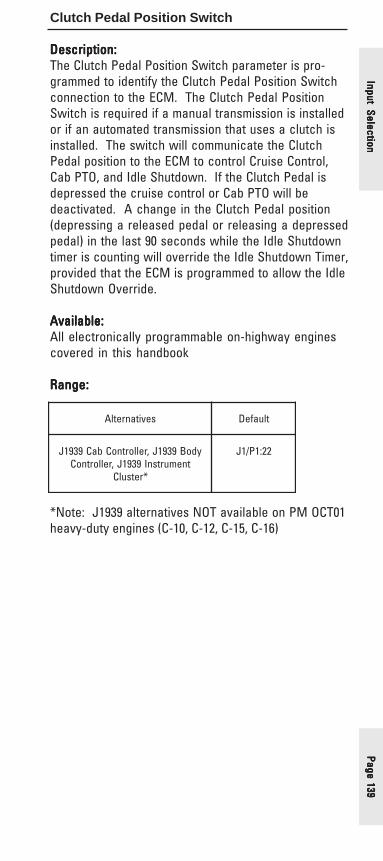
Page 139Page 139Page 139Page 139Page 139
Clutch Pedal Position Switch
Description:Description:Description:Description:Description:The Clutch Pedal Position Switch parameter is pro-grammed to identify the Clutch Pedal Position Switchconnection to the ECM. The Clutch Pedal PositionSwitch is required if a manual transmission is installedor if an automated transmission that uses a clutch isinstalled. The switch will communicate the ClutchPedal position to the ECM to control Cruise Control,Cab PTO, and Idle Shutdown. If the Clutch Pedal isdepressed the cruise control or Cab PTO will bedeactivated. A change in the Clutch Pedal position(depressing a released pedal or releasing a depressedpedal) in the last 90 seconds while the Idle Shutdowntimer is counting will override the Idle Shutdown Timer,provided that the ECM is programmed to allow the IdleShutdown Override.
Available:Available:Available:Available:Available:All electronically programmable on-highway enginescovered in this handbook
Range:Range:Range:Range:Range:
*Note: J1939 alternatives NOT available on PM OCT01heavy-duty engines (C-10, C-12, C-15, C-16)
sevitanretlA tluafeD
ydoB9391J,rellortnoCbaC9391JtnemurtsnI9391J,rellortnoC
*retsulC
22:1P/1J
Input SelectionInput SelectionInput SelectionInput SelectionInput Selection

Page
140
Page
140
Page
140
Page
140
Page
140
Starting Aid On/Off Switch
Description:Description:Description:Description:Description:The Starting Aid On/Off Switch parameter is pro-grammed to identify the type of connection theStarting Aid On/Off Switch has with the ECM. TheStarting Aid On/Off Switch is used to allow the opera-tor to enable or disable the ECM controlled StartingAid Output. If the switch is in the On position, the ECMwill automatically enable the Starting Aid Output whenconditions require the use of a starting aid. When theswitch is in the Off position, the Starting Aid systemwill not function.
Available:Available:Available:Available:Available:C-10, C-12, C-15, C-16, C11, C13, C15 heavy duty engines
Range:Range:Range:Range:Range:
sevitanretlA tluafeD
,64:1P/1J,7:1P/1J,6:1P/1J74:1P/1J
enoN
Inpu
t Se
lect
ion
Inpu
t Se
lect
ion
Inpu
t Se
lect
ion
Inpu
t Se
lect
ion
Inpu
t Se
lect
ion

Page 141Page 141Page 141Page 141Page 141
Retarder Off/Low/Med/High Switch
Description:Description:Description:Description:Description:The Retarder Off/Low/Med/High Switch parameteridentifies how the Retarder Off/Low/Med/High Switchis connected to the ECM. The switch itself controlsthe operation of the Engine Retarder Solenoids. If theswitch is to be hardwired to the ECM, the Low/HighInput should be wired to the ECM connector J1/P1terminal 23, and the Med/High Input to J1/P1 terminal40.
Available:Available:Available:Available:Available:C-10, C-12, C-15, C-16, C11, C13, C15 heavy duty engines
Range:Range:Range:Range:Range:
*Note: J1939 alternatives NOT available on PM OCT01heavy-duty engines (C-10, C-12, C-15, C-16)
sevitanretlA tluafeD
baC9391J,rellortnoCydoB9391JtnemurtsnI9391J,rellortnoC
*retsulC
04&32:1P/1J
Input SelectionInput SelectionInput SelectionInput SelectionInput Selection

Page
142
Page
142
Page
142
Page
142
Page
142
Out
put
Sele
ctio
nO
utpu
t Se
lect
ion
Out
put
Sele
ctio
nO
utpu
t Se
lect
ion
Out
put
Sele
ctio
nOutput Selection
• Fast Idle Enabled Lamp• Wait to Start Lamp• Fan Control Type• Change Oil Lamp• PTO Active Configuration Output• PTO Switch On Lamp• Engine Running Output• Starting Aid Output• Engine Shutdown Output• Auxiliary Brake• Air Inlet Shutoff Control Relay
Note that the Output Selections listed are not desig-nated as Factory, OEM Databook, or Optional. Outputselection connections are all options that are speci-fied at the factory. However, if features are addedoutside the factory, output selections can be speci-fied at that time. This section is included for com-pleteness due to its direct relation to the parametersdiscussed in this handbook.

Page 143Page 143Page 143Page 143Page 143
Fast Idle Enabled Lamp
Description:Description:Description:Description:Description:The Fast Idle Enabled Lamp parameter is available toindicate to the driver when the Fast Idle #1 or Fast Idle#2 operations are active. This parameter is pro-grammed as shown below, but requires that a momen-tary Fast Idle Switch is installed and the Fast Idle #1parameter is programmed to a valid speed above lowidle.
Available:Available:Available:Available:Available:3126E, C7, C9 medium-duty engines
Range:Range:Range:Range:Range:
sevitanretlA tluafeD
enoN,12:1P/1J 13:1P/1J
Output Selection
Output Selection
Output Selection
Output Selection
Output Selection

Page
144
Page
144
Page
144
Page
144
Page
144
Out
put
Sele
ctio
nO
utpu
t Se
lect
ion
Out
put
Sele
ctio
nO
utpu
t Se
lect
ion
Out
put
Sele
ctio
nWait to Start Lamp
Description:Description:Description:Description:Description:The Wait to Start Lamp parameter is programmed toconfigure the ECM to either turn on output J1/P1:31 orto send a message over the J1939 datalink to turn onthe attached lamp when the inlet air heater is on andthe engine is not running. This feature is differentfrom the Inlet Air Heater Lamp that will turn on when-ever the Inlet Air Heater is operating (with or withoutengine speed).
Available:Available:Available:Available:Available:3126E, C7, C9 medium-duty engines
Range:Range:Range:Range:Range:
*PM MAR04 and after
sevitanretlA tluafeD
*9391J,13:1P/1J enoN
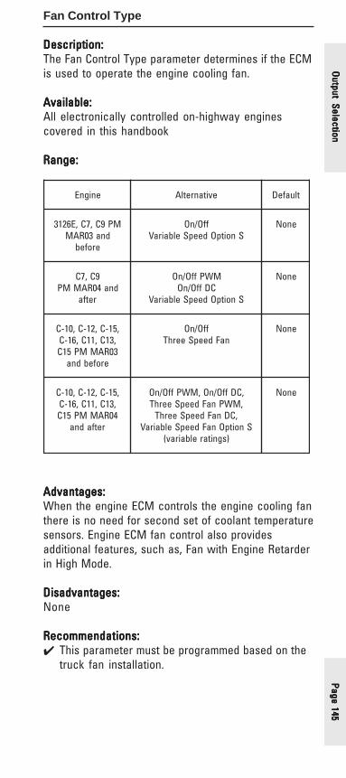
Page 145Page 145Page 145Page 145Page 145
Fan Control Type
Description:Description:Description:Description:Description:The Fan Control Type parameter determines if the ECMis used to operate the engine cooling fan.
Available:Available:Available:Available:Available:All electronically controlled on-highway enginescovered in this handbook
Range:Range:Range:Range:Range:
Advantages:Advantages:Advantages:Advantages:Advantages:When the engine ECM controls the engine cooling fanthere is no need for second set of coolant temperaturesensors. Engine ECM fan control also providesadditional features, such as, Fan with Engine Retarderin High Mode.
Disadvantages:Disadvantages:Disadvantages:Disadvantages:Disadvantages:None
Recommendations:Recommendations:Recommendations:Recommendations:Recommendations:✔ This parameter must be programmed based on the
truck fan installation.
enignE evitanretlA tluafeD
MP9C,7C,E6213dna30RAM
erofeb
ffO/nOSnoitpOdeepSelbairaV
enoN
9C,7Cdna40RAMMP
retfa
MWPffO/nOCDffO/nO
SnoitpOdeepSelbairaV
enoN
,51-C,21-C,01-C,31C,11C,61-C30RAMMP51C
erofebdna
ffO/nOnaFdeepSeerhT
enoN
,51-C,21-C,01-C,31C,11C,61-C40RAMMP51C
retfadna
,CDffO/nO,MWPffO/nO,MWPnaFdeepSeerhT
,CDnaFdeepSeerhTSnoitpOnaFdeepSelbairaV
)sgnitarelbairav(
enoN
Output Selection
Output Selection
Output Selection
Output Selection
Output Selection

Page
146
Page
146
Page
146
Page
146
Page
146
Change Oil Lamp
Description:Description:Description:Description:Description:The Change Oil Lamp parameter is used to turn on theChange Oil Lamp when, according to programmedmaintenance parameters, the engine is in need of anoil change. The Change Oil Lamp parameter must beprogrammed to the Default setting listed below inorder for this feature to work.
Available:Available:Available:Available:Available:3126E, C7, C9 medium-duty engines
Range:Range:Range:Range:Range:
sevitanretlA tluafeD
enoN 03:1P/1J
Out
put
Sele
ctio
nO
utpu
t Se
lect
ion
Out
put
Sele
ctio
nO
utpu
t Se
lect
ion
Out
put
Sele
ctio
n

Page 147Page 147Page 147Page 147Page 147
PTO Active Output Configuration
Description:Description:Description:Description:Description:The PTO Active Output Configuration parameter isactivated whenever the engine is actively in PTOmode.
Available:Available:Available:Available:Available:C7, C9 medium-duty engines
Range:Range:Range:Range:Range:
MP sevitanretlA tluafeD
30RAMMP 91:1P/1J enoN
40RAMMP enoN 91:1P/1J
Output Selection
Output Selection
Output Selection
Output Selection
Output Selection

Page
148
Page
148
Page
148
Page
148
Page
148
PTO Switch On Lamp
Description:Description:Description:Description:Description:The PTO Switch On Lamp parameter is used to enablea lamp output when programmed to the Default valuelisted below. This lamp is enabled whenever the PTOswitch is closed, but is not available when theWarning Lamp parameter is programmed to Option 1.
Available:Available:Available:Available:Available:3126E, C7, C9 medium-duty engines
Range:Range:Range:Range:Range:
Advantages:Advantages:Advantages:Advantages:Advantages:This parameter provides enables a lamp that will notifythe truck operator when the engine is in PTO mode.
sevitanretlA tluafeD
enoN 03:1P/1J
Out
put
Sele
ctio
nO
utpu
t Se
lect
ion
Out
put
Sele
ctio
nO
utpu
t Se
lect
ion
Out
put
Sele
ctio
n

Page 149Page 149Page 149Page 149Page 149
Engine Running Output
Description:Description:Description:Description:Description:The Engine Running Output is used to allow the ECMto drive a solenoid or relay to prevent the starter frombeing engaged while the engine is running. TheEngine Running Output enables when the enginespeed reaches 50 rpm below the programmed Low Idlerpm, and then disables when the engine speed falls100 rpm below the programmed Low Idle rpm.
Available:Available:Available:Available:Available:All on-highway engines covered in this handbook (notavailable to all OEMs)
Range:Range:Range:Range:Range:
Advantages:Advantages:Advantages:Advantages:Advantages:Programming this parameter prevents unnecessarywear on the starter.
enignE sevitanretlA tluafeD
9C,7C,E6213 13:1P/1J enoN
,61-C,51-C,21-C,01-C51C,31C,11C
,01:1P/1J31:1P/1J,21:1P/1J
enoN
Output Selection
Output Selection
Output Selection
Output Selection
Output Selection

Page
150
Page
150
Page
150
Page
150
Page
150
Starting Aid Output
Description:Description:Description:Description:Description:The Starting Aid Output parameter is programmed tospecify the type of control used for the Starting AidOutput. The output can be either automaticallycontrolled by the ECM, or a manual switch can beinstalled and connected to the ECM for operatorcontrol, as specified below.
Available:Available:Available:Available:Available:3126E, C7, C9 (before PM MAR04), C-10, C-12, C-15, C-16,C11, C13, C15
Range:Range:Range:Range:Range:
enignE sevitanretlA tluafeD
erofeb(9C,7C,E6213)40RAMMP
citamotuA ffO
,61-C,51-C,21-C,01-C51C,31C,11C
,01:1P/1J31:1P/1J,21:1P/1J
enoN
Out
put
Sele
ctio
nO
utpu
t Se
lect
ion
Out
put
Sele
ctio
nO
utpu
t Se
lect
ion
Out
put
Sele
ctio
n

Page 151Page 151Page 151Page 151Page 151
Engine Shutdown Output
Description:Description:Description:Description:Description:The Engine Shutdown Output parameter is used tospecify the ECM output pin for the Engine ShutdownOutput. This feature is used to shutdown the vehicleelectrical system after the idle timer has expired. TheEngine Shutdown Output comes on after the enginehas been running for more than 3 seconds, and thenturns off when the engine rpm is at least 100 rpm belowlow idle for more than 3 seconds.
Available:Available:Available:Available:Available:C-10, C-12, C-15, C-16, C11, C13, C15 heavy duty engines
Range:Range:Range:Range:Range:
sevitanretlA tluafeD
,01:1P/1J31:1P/1J,21:1P/1J
enoN
Output Selection
Output Selection
Output Selection
Output Selection
Output Selection
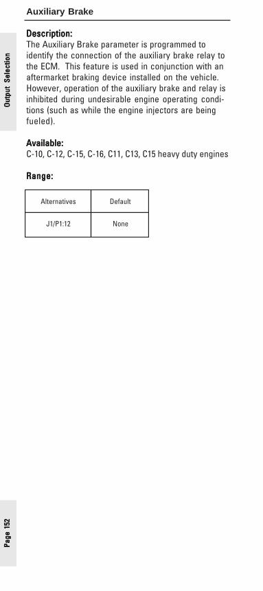
Page
152
Page
152
Page
152
Page
152
Page
152
Auxiliary Brake
Description:Description:Description:Description:Description:The Auxiliary Brake parameter is programmed toidentify the connection of the auxiliary brake relay tothe ECM. This feature is used in conjunction with anaftermarket braking device installed on the vehicle.However, operation of the auxiliary brake and relay isinhibited during undesirable engine operating condi-tions (such as while the engine injectors are beingfueled).
Available:Available:Available:Available:Available:C-10, C-12, C-15, C-16, C11, C13, C15 heavy duty engines
Range:Range:Range:Range:Range:
sevitanretlA tluafeD
21:1P/1J enoN
Out
put
Sele
ctio
nO
utpu
t Se
lect
ion
Out
put
Sele
ctio
nO
utpu
t Se
lect
ion
Out
put
Sele
ctio
n

Page 153Page 153Page 153Page 153Page 153
Air Inlet Shutoff Control Relay
Description:Description:Description:Description:Description:The Air Inlet Shutoff Control Relay parameter is used toidentify the Air Inlet Shutoff Control Relay to the ECM.Programming this parameter will enable the ECM tocontrol the relay via the J2/P2:13 connection specifiedbelow.
The Air Inlet Shutoff device is used to prevent theengine from over-speeding due to ingesting combus-tible gas present in the ambient air. This feature shutsoff the inlet air to the engine by closing a spring-loaded flap on the air inlet when the conditions aremet to energize the relay. These conditions are zerovehicle speed, battery voltage on the Neutral Switchinput, throttle at minimum, and engine speed over 2500rpm.
Available:Available:Available:Available:Available:C11, C13, C15 PM MAR04 and after (specific ratingsonly)
Range:Range:Range:Range:Range:
Advantages:Advantages:Advantages:Advantages:Advantages:Programming this parameter to the Alternative listedabove will give over-speed protection to an Air InletShutoff-equipped engine.
Disadvantages:Disadvantages:Disadvantages:Disadvantages:Disadvantages:If the Air Inlet Shutoff Relay is energized too long,serious damage to the relay can occur.
Recommendations:Recommendations:Recommendations:Recommendations:Recommendations:✔ Only allow the Air Inlet Shutoff Relay to be ener-
gized for between 1 and 2 seconds to preventdamage to the relay.
sevitanretlA tluafeD
enoN 31:2P/2J
Output Selection
Output Selection
Output Selection
Output Selection
Output Selection
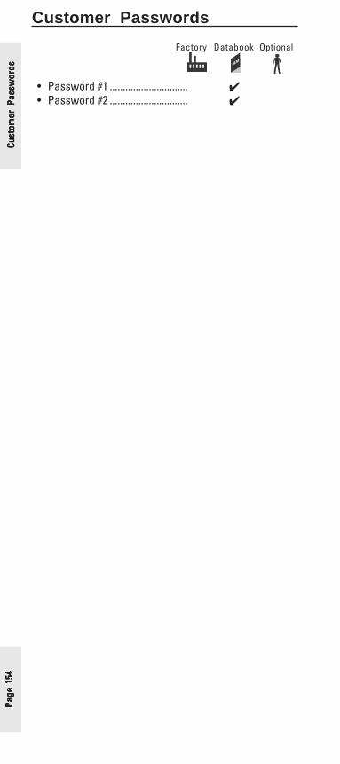
Page
154
Page
154
Page
154
Page
154
Page
154
Cust
omer
Pas
swor
dsCu
stom
er P
assw
ords
Cust
omer
Pas
swor
dsCu
stom
er P
assw
ords
Cust
omer
Pas
swor
dsCustomer Passwords
Factory Databook Optional
• Password #1 .............................. ✔• Password #2 .............................. ✔
Page 155Page 155Page 155Page 155Page 155
Customer Password #1Customer Password #2
Description:Description:Description:Description:Description:To protect the engine against unauthorized repro-gramming once the parameters are set, the customercan specify either one or two passwords to controlaccess to the parameters stored in the electroniccontrol module (ECM). However, the use of passwordsis not required for Cat electronic engines to operate.Both passwords can be up to eight alphanumericcharacters in length.
Once these passwords are programmed, they arerequired to gain access to the customer specifiedparameters. No one can change the pre-programmedCruise Control parameter for instance, even if theywere to have access to a service tool, without alsoknowing the correct password(s).
If the password is misplaced or forgotten the customerwill have to contact either his Caterpillar dealer orauthorized truck dealer to view the passwords. Thisrequires a higher level of security called a factorypassword.
Available:Available:Available:Available:Available:All Electronically Controlled Engines
Range:Range:Range:Range:Range:
Advantages:Advantages:Advantages:Advantages:Advantages:Programming in a password or words help make thecustomer’s electronics specifications more secureand resistant to tampering.
Disadvantages:Disadvantages:Disadvantages:Disadvantages:Disadvantages:If the password(s) is(are) forgotten, arrangementsmust be made with an authorized dealer to obtain afactory password.
Recommendations:Recommendations:Recommendations:Recommendations:Recommendations:✔ Caterpillar recommends that electronic engines be
protected by passwords and that those passwordsbe kept secure.
Customer Passw
ordsCustom
er Passwords
Customer Passw
ordsCustom
er Passwords
Customer Passw
ords

Page
156
Page
156
Page
156
Page
156
Page
156
Dat
a Li
nk P
aram
eter
sD
ata
Link
Par
amet
ers
Dat
a Li
nk P
aram
eter
sD
ata
Link
Par
amet
ers
Dat
a Li
nk P
aram
eter
sData Link Parameters
Factory Databook Optional
• Powertrain Data Link .............✔
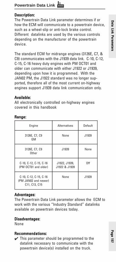
Page 157Page 157Page 157Page 157Page 157
Powertrain Data Link
Description:Description:Description:Description:Description:The Powertrain Data Link parameter determines if orhow the ECM will communicate to a powertrain device,such as a wheel-slip or anti-lock brake control.Different datalinks are used by the various controlsdepending on the manufacturer of the powertraindevice.
The standard ECM for midrange engines (3126E, C7, &C9) communicates with the J1939 data link. C-10, C-12,C-15, C-16 heavy duty engines with PM OCT01 andolder can communicate with either J1922 or J1939,depending upon how it is programmed. With theJAN02 PM, the J1922 standard was no longer sup-ported, therefore all of the most current on-highwayengines support J1939 data link communication only.
Available:Available:Available:Available:Available:All electronically controlled on-highway enginescovered in this handbook
Range:Range:Range:Range:Range:
Advantages:Advantages:Advantages:Advantages:Advantages:The Powertrain Data Link parameter allows the ECM towork with the various “Industry Standard” datalinksavailable on powertrain devices today.
Disadvantages:Disadvantages:Disadvantages:Disadvantages:Disadvantages:None
Recommendations:Recommendations:Recommendations:Recommendations:Recommendations:✔ This parameter should be programmed to the
datalink necessary to communicate with thepowertrain device(s) installed on the truck.
enignE sevitanretlA tluafeD
9C,7C,E6213MG
enoN 9391J
9C,7C,E6213rehtO
9391J enoN
61-C,51-C,21-C,01-C)redlodna10TCOMP(
,9391J,2291J9391J&2291J
ffO
61-C,51-C,21-C,01-C)rewendna20NAJMP(
51C,31C,11C
enoN 9391J
Data Link Param
etersD
ata Link Parameters
Data Link Param
etersD
ata Link Parameters
Data Link Param
eters

Page
158
Page
158
Page
158
Page
158
Page
158
Special Parameters
Factory Databook Optional
• Customer ParameterLockout .....................................✔ ✔
Spec
ial
Para
met
ers
Spec
ial
Para
met
ers
Spec
ial
Para
met
ers
Spec
ial
Para
met
ers
Spec
ial
Para
met
ers

Page 159Page 159Page 159Page 159Page 159
Customer Parameter Lockout
Description:Description:Description:Description:Description:If a security level higher than a customer password(s)(see page 154) is required, either by the customer orlocal laws, the following parameters can be ”lockedout”.
• Vehicle Speed Limit• Vehicle Speed Calibration• High Cruise Control Speed Set Limit• Top Engine Limit• Soft Vehicle Speed Limit• A/C Pressure Switch Fan-On Time• Driver Reward Enable• Engine Monitoring Lamps• Engine Retarder Delay• Fan Control Type• High Speed Range Axle Ratio• Low Speed Range Axle Ratio• Multi-Torque Ratio• Top Gear Minus One Ratio• Top Gear Minus Two Ratio• Top Gear Ratio• Transmission Style• Vehicle Overspeed Protection
These parameters have been labeled throughout thisbook with the icon in the title bar.
Available:Available:Available:Available:Available:All electronically controlled on-highway enginescovered in this handbook
Range:Range:Range:Range:Range:
Advantages:Advantages:Advantages:Advantages:Advantages:The ability to lock certain critical parameters tocomply with either local laws or customer requests.
Disadvantages:Disadvantages:Disadvantages:Disadvantages:Disadvantages:None
Recommendations:Recommendations:Recommendations:Recommendations:Recommendations:✔ Lock only those parameters that either required by
local laws or customer request.
Customer Param
eter LockoutCustom
er Parameter Lockout
Customer Param
eter LockoutCustom
er Parameter Lockout
Customer Param
eter Lockout
egnaR tluafeD
dekcolnUdekcoL
dekcolnU

Page
160
Page
160
Page
160
Page
160
Page
160
Trip
Dat
aTr
ip D
ata
Trip
Dat
aTr
ip D
ata
Trip
Dat
aTrip Data
• Current Totals .......................................... page 161• Fleet Trip ................................................... page 162• Driver Trip ................................................. page 163• Histograms ............................................... page 164• Custom Data ............................................ page 165
Various totals are stored in the ECM memory on on-highway engines. This data is called Trip Data Trip Data Trip Data Trip Data Trip Data. Thisdata is divided into three major categories; CurrentTotals, Fleet Trip and Driver Trip. The ECM also usesthis data to create Histograms that show engineoperation and driving habits. The ECM can also beindividually programmed to record data based onvarious parameters, as requested by an owner or fleet,by using the Custom Data feature.
The Trip Data can be viewed various ways:Cat ID (Cat Messenger) Dash Display - The Cat ID or
Cat Messenger can view the Current Totals, FleetTrip and Driver Trip data.
Fleet Information Software (FIS) - Can view, analyzeand create custom reports of all the Trip Data (Seepage 169).
ECAP & ET - These Service Tools can view all thevarious Trip Data.

Page 161Page 161Page 161Page 161Page 161
Current Totals
Description:Description:Description:Description:Description:The ECM calculates and stores lifetime information.
This information includes:• Total Engine Hours - Engine Running Hours• Total Distance• Total Fuel Used - Including Idle and PTO Fuel Used• PTO Hours• PTO Fuel• Idle Hours• Idle Fuel• Engine Load Factor
This information is available through the service tools,FIS and Cat Driver Information Display (Cat ID)/CatMessenger.
If an ECM needs to be replaced, the Current Totalscan be programmed into the replacement ECM.
Available:Available:Available:Available:Available:All electronically controlled on-highway enginescovered in this handbook
Trip Data
Trip Data
Trip Data
Trip Data
Trip Data

Page
162
Page
162
Page
162
Page
162
Page
162
Trip
Dat
aTr
ip D
ata
Trip
Dat
aTr
ip D
ata
Trip
Dat
aFleet Trip Totals
Description:Description:Description:Description:Description:The ECM can store certain information in a Fleet TripTotal. The length of this data is user dependent. TheFleet Trip Reset can be performed by a service tool,Fleet Information Software (FIS) or the CaterpillarDriver Information Display Cat ID or Cat Messenger, ifprogrammed to do so (see page 107).
This information includes:• Hours • Distance• Fuel Used • Average Load Factor• Fuel Economy • Average Vehicle Speed• Max. Engine Speed • Max. Vehicle Speed• Idle Hours • PTO Hours• Idle Fuel • PTO Fuel• % Idle Hours • % PTO Hours
Available:Available:Available:Available:Available:All electronically controlled on-highway enginescovered in this handbook

Page 163Page 163Page 163Page 163Page 163
Driver Trip Totals
Description:Description:Description:Description:Description:The ECM can store certain information in a Driver TripTotal. The length of this data is user dependent. TheDriver Trip Reset can be performed by a service tool,Fleet Information Software (FIS) or the CaterpillarDriver Information Display (Cat ID)/Cat Messenger.
This information includes:• Hours • Distance• Fuel Used • Average Load Factor• Fuel Economy • Average Vehicle Speed• Max. Engine Speed • Max. Vehicle Speed• Idle Hours • PTO Hours• Idle Fuel • PTO Fuel• % Idle Hours • % PTO Hours
Since this data can be reset by the driver at anytime, itcan be a subset of the Fleet Trip Totals.
An example can be the Fleet Trip and Driver Trip datacould be reset at the same time at the beginning of thetrip. The driver could then manually record the DriverTrip Data when he/she reached their first destination.After recording the data, the driver would reset theDriver Trip Data and proceed on with the next leg ofthe trip, manually recording and resetting after eachleg. Upon arriving back at home base the driver wouldhave the various segments written down and the ECMwould have the data for the entire trip stored in theFleet Trip Data. An evaluation could then be made,using the overall Fleet Trip Totals and the variousDriver Trip Totals of each leg.
Available:Available:Available:Available:Available:C-10, C-12, C-15, C-16, C11, C13, & C15 heavy dutyengines
Trip Data
Trip Data
Trip Data
Trip Data
Trip Data

Page
164
Page
164
Page
164
Page
164
Page
164
Trip
Dat
aTr
ip D
ata
Trip
Dat
aTr
ip D
ata
Trip
Dat
aHistograms
Description:Description:Description:Description:Description:The ECM records the amount of time that the truck hasbeen operated at various RPM and MPH. This timeinformation is stored in “buckets”. The RPM bucketsare 100 RPM segments. The MPH are in 5 MPH seg-ments. This information is displayed on the service toolor Fleet Information Software (FIS) as a bar chartcalled a histogram. FIS also displays a 3 dimensionalhistogram to evaluate engine operation and drivereffectiveness.
The histogram time period is the same as the Fleet Tripdata.
Available:Available:Available:Available:Available:All electronically controlled on-highway enginescovered in this handbook
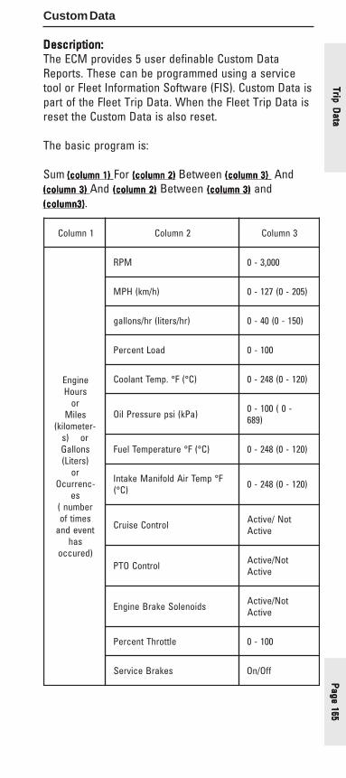
Page 165Page 165Page 165Page 165Page 165
Custom Data
Description:Description:Description:Description:Description:The ECM provides 5 user definable Custom DataReports. These can be programmed using a servicetool or Fleet Information Software (FIS). Custom Data ispart of the Fleet Trip Data. When the Fleet Trip Data isreset the Custom Data is also reset.
The basic program is:
Sum (column 1)(column 1)(column 1)(column 1)(column 1) For (column 2)(column 2)(column 2)(column 2)(column 2) Between (column 3)(column 3)(column 3)(column 3)(column 3) And(column 3) (column 3) (column 3) (column 3) (column 3) And (column 2)(column 2)(column 2)(column 2)(column 2) Between (column 3)(column 3)(column 3)(column 3)(column 3) and(column3)(column3)(column3)(column3)(column3).
1nmuloC 2nmuloC 3nmuloC
enignEsruoH
roseliM
-retemolik(ro)ssnollaG)sretiL(
ro-cnerrucO
serebmun(
semitfotnevedna
sah)derucco
MPR 000,3-0
)h/mk(HPM )502-0(721-0
)rh/sretil(rh/snollag )051-0(04-0
daoLtnecreP 001-0
)C°(F°.pmeTtnalooC )021-0(842-0
)aPk(isperusserPliO -0(001-0)986
)C°(F°erutarepmeTleuF )021-0(842-0
F°pmeTriAdlofinaMekatnI)C°( )021-0(842-0
lortnoCesiurC toN/evitcAevitcA
lortnoCOTP toN/evitcAevitcA
sdioneloSekarBenignE toN/evitcAevitcA
elttorhTtnecreP 001-0
sekarBecivreS ffO/nO
Trip Data
Trip Data
Trip Data
Trip Data
Trip Data

Page
166
Page
166
Page
166
Page
166
Page
166
Example:To find the number of gallons of fuel used when thetruck was traveling between 55 and 65 MPH.
Sum GallonsGallonsGallonsGallonsGallons for MPHMPHMPHMPHMPH between 5555555555 and 6565656565
This would store the number of gallons of fuel usedduring the current Fleet Trip Segment when the truckwas traveling between 55 and 65 MPH.
Available:Available:Available:Available:Available:All electronically controlled on-highway enginescovered in this handbook
Trip
Dat
aTr
ip D
ata
Trip
Dat
aTr
ip D
ata
Trip
Dat
a
Page 167Page 167Page 167Page 167Page 167
Miscellaneous Information
• Multi-Torque Ratings• Multi-Torque Ratios• Triggering Snapshots• Cat ID (Cat Messenger)• Fleet Information Software (FIS)• Cat® Design Pro
Miscellaneous Inform
ationM
iscellaneous Information
Miscellaneous Inform
ationM
iscellaneous Information
Miscellaneous Inform
ation
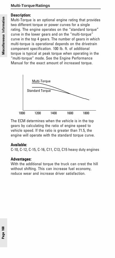
Page
168
Page
168
Page
168
Page
168
Page
168
Multi-Torque Ratings
Description:Description:Description:Description:Description:Multi-Torque is an optional engine rating that providestwo different torque or power curves for a singlerating. The engine operates on the “standard torque”curve in the lower gears and on the “multi-torque”curve in the top 4 gears. The number of gears in whichmulti-torque is operational depends on the drivetraincomponent specification. 100 lb. ft. of additionaltorque is typical at peak torque when operating in the“multi-torque” mode. See the Engine PerformanceManual for the exact amount of increased torque.
1000 1200 1400 1600 1800
Multi-Torque
Standard Torque
The ECM determines when the vehicle is in the topgears by calculating the ratio of engine speed tovehicle speed. If the ratio is greater than 71.5, theengine will operate with the standard torque curve.
Available:Available:Available:Available:Available:C-10, C-12, C-15, C-16, C11, C13, C15 heavy duty engines
Advantages:Advantages:Advantages:Advantages:Advantages:With the additional torque the truck can crest the hillwithout shifting. This can increase fuel economy,reduce wear and increase driver satisfaction.
Mis
cella
neou
s In
form
atio
nM
isce
llane
ous
Info
rmat
ion
Mis
cella
neou
s In
form
atio
nM
isce
llane
ous
Info
rmat
ion
Mis
cella
neou
s In
form
atio
n

Page 169Page 169Page 169Page 169Page 169
enignE egnaR tluafeD
ytuDyvaeH40RAMMP-erP 1-TM,2-TM 4-TM
ytuDyvaeHretfA&40RAMMP C-TM,B-TM A-TM
Multi-Torque Ratios
Description:Description:Description:Description:Description:This parameter is used to select the desired Multi-Torque trip point. Multi-Torque ratings allow theengine to provide additional torque or additionalhorsepower and torque when the transmission isoperating in higher gears. The trip point is determinedby a ratio of engine speed versus vehicle speed. Thethree programmable options represent the differenttrip point values listed below:
Pre-PM MAR04Pre-PM MAR04Pre-PM MAR04Pre-PM MAR04Pre-PM MAR04MT-4: MT-4: MT-4: MT-4: MT-4: Turn on ratio is 71.5 rpm/mph & below(Top 4 Gears)MT-2: MT-2: MT-2: MT-2: MT-2: Turn on ratio is 37.6 rpm/mph & below(Top 2 Gears)MT-1: MT-1: MT-1: MT-1: MT-1: Turn on ratio is 27.9 rpm/mph & below(Top 1 Gear)
PM MAR04 and AfterPM MAR04 and AfterPM MAR04 and AfterPM MAR04 and AfterPM MAR04 and AfterMT-C: MT-C: MT-C: MT-C: MT-C: Turn on ratio is 38 rpm/mph & below(Top 4 Gears)MT-B: MT-B: MT-B: MT-B: MT-B: Turn on ratio is 33 rpm/mph & below(Top 2 Gears)MT-A: MT-A: MT-A: MT-A: MT-A: Turn on ratio is 27.9 rpm/mph & below(Top 1 Gear)
NOTE: NOTE: NOTE: NOTE: NOTE: This feature is not used with standard engineratings, it is only available for Multi-Torque ratings.
Available:Available:Available:Available:Available:Heavy duty electronically controlled on-highwayengines covered in this handbook
Range:Range:Range:Range:Range:
Miscellaneous Inform
ationM
iscellaneous Information
Miscellaneous Inform
ationM
iscellaneous Information
Miscellaneous Inform
ation

Page
170
Page
170
Page
170
Page
170
Page
170
Mis
cella
neou
s In
form
atio
nM
isce
llane
ous
Info
rmat
ion
Mis
cella
neou
s In
form
atio
nM
isce
llane
ous
Info
rmat
ion
Mis
cella
neou
s In
form
atio
nTriggering Snapshots
Description:Description:Description:Description:Description:The Engine ECM saves certain information for use introubleshooting any time a fault code is logged. Thereis also a method to manually trigger snapshots usingthe Set/Resume cruise control switch. By toggling theswitch from the “center-off” position, up to the Setposition and down to the Resume position and back tothe “center-off” position (or vice-versa) within a onesecond time period, a snapshot of the engine param-eters will be taken. Only the 4 most recent manuallytriggered snapshots can be stored at anytime.
Set
Resume
Available:Available:Available:Available:Available:All electronically controlled on-highway enginescovered in this handbook
Advantages:Advantages:Advantages:Advantages:Advantages:The driver who is experiencing an intermittent problemcan aid in the troubleshooting of the problem by takinga “snapshot” when experiencing the problem. Asnapshot records 13 seconds of engine data, 9seconds before the trigger and 4 seconds after thetrigger. This snapshot information can then be viewedby a technician using a service tool.
Disadvantages:Disadvantages:Disadvantages:Disadvantages:Disadvantages:None
Page 171Page 171Page 171Page 171Page 171
Cat ID/ Cat Messenger
Description:Description:Description:Description:Description:The Cat Messenger has replaced the CaterpillarInformation Display (ID), but existing Cat IDs are still inuse today. The Cat Messenger or Cat ID is a cabmounted display device. It can be ordered as anoption from the truck manufacturer or retro fitted inany appropriately equipped on-highway vehicle. Itcan display a wide variety of information; DiagnosticData, Engine Operating Information, Vehicle TripInformation, Trip Information and is an integral part ofthe Theft Deterrent system. Cat Messenger or Cat IDcan display the information in both English and Metricunits as well as in English , Spanish or French Lan-guages.
For a complete description of the Caterpillar Messen-ger or the Caterpillar Information Display (ID), refer tothe Operation and Maintenance Manual for yourengine.
Available:Available:Available:Available:Available:All electronically controlled on-highway enginescovered in this handbook
Miscellaneous Inform
ationM
iscellaneous Information
Miscellaneous Inform
ationM
iscellaneous Information
Miscellaneous Inform
ation

Page
172
Page
172
Page
172
Page
172
Page
172
Mis
cella
neou
s In
form
atio
nM
isce
llane
ous
Info
rmat
ion
Mis
cella
neou
s In
form
atio
nM
isce
llane
ous
Info
rmat
ion
Mis
cella
neou
s In
form
atio
nFleet Information Software
Description:Description:Description:Description:Description:The Caterpillar Fleet Information Software is a platformfor extraction, analysis and historical file storage ofinformation generated for Caterpillar truck engines.Additional information is available in Product NewsLEXT4442.
Available:Available:Available:Available:Available:All electronically controlled on-highway enginescovered in this handbook
Advantages:Advantages:Advantages:Advantages:Advantages:The Caterpillar Fleet Information Software wasdeveloped to assist fleet managers in monitoring andimproving the overall performance of their fleet. This isaccomplished through analysis of daily, weekly andannual performance of vehicles and drivers. Inaddition to providing a platform for extraction, analysisand historical file storage of information generated bytruck engines, the Fleet Information Software can alsobe used to upload information and various parametersinto the engine’s electronic control module (ECM). ThePC Windows (3.1) based application is menu drivenand focuses on the following major categories:Information DownloadInformation DownloadInformation DownloadInformation DownloadInformation Download - Three quick, straightforward andreliable methods for downloading are provided. Allengine electronic control module Trip data is down-loaded and reset automatically.Information UploadInformation UploadInformation UploadInformation UploadInformation Upload - Information such as maintenanceparameters, custom report definitions, Vehicle ID, andfuel correction factor, may be modified using FIS, andautomatically uploaded to the ECM during the nextgeneration of data.Information AnalysisInformation AnalysisInformation AnalysisInformation AnalysisInformation Analysis - FIS offers the user a flexible toolfor analyzing data from one to an entire fleet ofengines. Data may be sorted by specific driver,vehicle, route, state or province. Sorted data can beused for generating a wide variety of reports.Customer Parameter Cross-CheckingCustomer Parameter Cross-CheckingCustomer Parameter Cross-CheckingCustomer Parameter Cross-CheckingCustomer Parameter Cross-Checking - FIS records theCustomer Programmable features of each truck andthen verifies that those parameters have not beenchanged.
Important Note:Important Note:Important Note:Important Note:Important Note:FIS is in the process of being revitalized to a web-based software system. This “next generation” FISwill feature additional reports in the form of servicepackages, effortless updates, and improved capabili-ties. Look for the new FIS in 2006.

Page 173Page 173Page 173Page 173Page 173
Cat Design Pro
Formerly Cat Truck Engine Pro, Cat Design Pro featuresimproved navigation tools, updated options, step-by-step spec’ing instructions, International units ofmeasure, redesigned route simulations, and real-time,current engine information including legacy supportback to 2001.
The secret to a “good” truck spec is through analysisof a customer’s performance requirements and thecorrect selection of driveline components to maximizeperformance and fuel economy. Cat Design Pro is aWeb-based software program that provides the abilityto compare performance of specific driveline compo-nent combinations. It also includes an industry-exclusive route simulation program where selectedspecifications can be run on more than 30,000 miles ofU.S. and Canadian interstate routes to more accuratelyevaluate vehicle performance.
• Route Simulation• Compare up to 4 different driveline specifications
at one time• Operational Analysis providing life cycle costs• Dealer Locator• Presentation Generation• Proposal Generation• Specification Summaries
For more information order LEDT3882 from the Caterpil-lar Literature System
Packed with the latest enhancements in spec’ingsoftware, Design Pro accomplishes much more than itspredecessors. Design Pro is an inexpensive invest-ment to ensure that new vehicles are spec’ed prop-erly, and that your customers receive the accuratebalance between fuel economy and performance fortheir unique applications.
Experience spec’ing on a whole new level by orderingCat Design Pro today. For details or to see a demo ofDesign Pro on-line, contact your Cat Truck EngineAccount Manager.
Miscellaneous Inform
ationM
iscellaneous Information
Miscellaneous Inform
ationM
iscellaneous Information
Miscellaneous Inform
ation
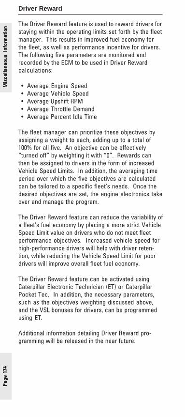
Page
174
Page
174
Page
174
Page
174
Page
174
Driver Reward
The Driver Reward feature is used to reward drivers forstaying within the operating limits set forth by the fleetmanager. This results in improved fuel economy forthe fleet, as well as performance incentive for drivers.The following five parameters are monitored andrecorded by the ECM to be used in Driver Rewardcalculations:
• Average Engine Speed• Average Vehicle Speed• Average Upshift RPM• Average Throttle Demand• Average Percent Idle Time
The fleet manager can prioritize these objectives byassigning a weight to each, adding up to a total of100% for all five. An objective can be effectively“turned off” by weighting it with “0”. Rewards canthen be assigned to drivers in the form of increasedVehicle Speed Limits. In addition, the averaging timeperiod over which the five objectives are calculatedcan be tailored to a specific fleet’s needs. Once thedesired objectives are set, the engine electronics takeover and manage the program.
The Driver Reward feature can reduce the variability ofa fleet’s fuel economy by placing a more strict VehicleSpeed Limit value on drivers who do not meet fleetperformance objectives. Increased vehicle speed forhigh-performance drivers will help with driver reten-tion, while reducing the Vehicle Speed Limit for poordrivers will improve overall fleet fuel economy.
The Driver Reward feature can be activated usingCaterpillar Electronic Technician (ET) or CaterpillarPocket Tec. In addition, the necessary parameters,such as the objectives weighting discussed above,and the VSL bonuses for drivers, can be programmedusing ET.
Additional information detailing Driver Reward pro-gramming will be released in the near future.
Mis
cella
neou
s In
form
atio
nM
isce
llane
ous
Info
rmat
ion
Mis
cella
neou
s In
form
atio
nM
isce
llane
ous
Info
rmat
ion
Mis
cella
neou
s In
form
atio
n
Page 175Page 175Page 175Page 175Page 175
Improving Fuel Economy
• Trip Preparation Tips• Driving Tips• Spec’ing Recommendations
Improving Fuel Econom
yIm
proving Fuel Economy
Improving Fuel Econom
yIm
proving Fuel Economy
Improving Fuel Econom
y

Page
176
Page
176
Page
176
Page
176
Page
176
Trip Preparation
Achieving improved fuel economy begins even beforethe engine is started. Trip preparation is fundamentalto ensuring efficient fuel economy once your vehicleis on the road. The following are Caterpillar recom-mendations for trip preparation that are sure to bringabout improved fuel economy.
Check Tire PressureCheck Tire PressureCheck Tire PressureCheck Tire PressureCheck Tire PressureImproperly inflated tires can drastically reduce fueleconomy as well as diminish the life expectancy of thetires themselves.
Limit “Warm - Up” Time:Limit “Warm - Up” Time:Limit “Warm - Up” Time:Limit “Warm - Up” Time:Limit “Warm - Up” Time:Excessive idling wastes fuel, adds contaminates to theoil, and adds carbons to the combustion chamber ofyour engine. Allow the engine to warm up during thenormal walk-around inspection. The engine willapproach operating temperature while driving at lowrpm and low power as you begin your trip.
Avoid Rapid Starts:Avoid Rapid Starts:Avoid Rapid Starts:Avoid Rapid Starts:Avoid Rapid Starts:Rapid starts burn excessive fuel because the engine iswinding to high a high rpm. Instead, utilize theprogressive shifting technique (outlined on thefollowing page).
Impr
ovin
g Fu
el E
cono
my
Impr
ovin
g Fu
el E
cono
my
Impr
ovin
g Fu
el E
cono
my
Impr
ovin
g Fu
el E
cono
my
Impr
ovin
g Fu
el E
cono
my

Page 177Page 177Page 177Page 177Page 177
Driving Tips
Keep Vehicle Speed Down:Keep Vehicle Speed Down:Keep Vehicle Speed Down:Keep Vehicle Speed Down:Keep Vehicle Speed Down:Fuel economy drops by 0.10 mpg for every 1 mph over55 mph.
Cruise in Top Gear:Cruise in Top Gear:Cruise in Top Gear:Cruise in Top Gear:Cruise in Top Gear:For maximum fuel economy, utilize the following shiftparameters:
1. Operate highest gear possible/do not run one gear down2. Keep the engine below 1500 rpm3. Downshift around 1100 rpm4. Use progressive shifting techniques
-Upshift around 1400-1500 rpm in upper gears-Upshift around 1100-1300 rpm in lower gears
Use Cruise Control Whenever Possible:Use Cruise Control Whenever Possible:Use Cruise Control Whenever Possible:Use Cruise Control Whenever Possible:Use Cruise Control Whenever Possible:Using cruise control helps maintain average speedand good fuel economy.
Avoid Downshifting too Early When Climbing GradesAvoid Downshifting too Early When Climbing GradesAvoid Downshifting too Early When Climbing GradesAvoid Downshifting too Early When Climbing GradesAvoid Downshifting too Early When Climbing GradesCaterpillar engines allow you to “lug the engine” (i.e.operate at 1000-1200 rpm), as long as the enginemaintains road speed while climbing a grade in the1000-1200 rpm range. In this situation, there is no needto downshift.
Do Not Run with “Fan On” Unless RequiredDo Not Run with “Fan On” Unless RequiredDo Not Run with “Fan On” Unless RequiredDo Not Run with “Fan On” Unless RequiredDo Not Run with “Fan On” Unless RequiredThe fan draws horsepower and reduces fuel economy.Under normal operating conditions, leave the fanswitch in the automatic mode while driving, whichallows the fan to activate only when needed.
Stay Alert to Changing Road ConditionsStay Alert to Changing Road ConditionsStay Alert to Changing Road ConditionsStay Alert to Changing Road ConditionsStay Alert to Changing Road ConditionsAnticipate possible slowdowns and stops, and coastin gear to improve overall fuel economy.
Eliminate Idle TimeEliminate Idle TimeEliminate Idle TimeEliminate Idle TimeEliminate Idle TimeCaterpillar engines with ACERT©©©©© Technology do notrequire long cool-down periods. Therefore, do not idlefor long periods of time.
-If the vehicle is to parked for more than 5 minutes, shut it down-If idling for heating or cooling, idle between 800-1000 rpm
Please note that a reduction in idle time from 50% to25% can improve mpg by 2-4%
Improving Fuel Econom
yIm
proving Fuel Economy
Improving Fuel Econom
yIm
proving Fuel Economy
Improving Fuel Econom
y
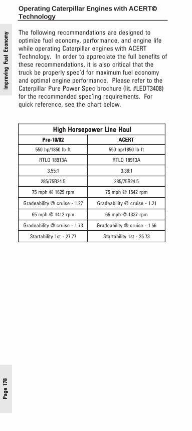
Page
178
Page
178
Page
178
Page
178
Page
178
Operating Caterpillar Engines with ACERT©©©©©Technology
The following recommendations are designed tooptimize fuel economy, performance, and engine lifewhile operating Caterpillar engines with ACERTTechnology. In order to appreciate the full benefits ofthese recommendations, it is also critical that thetruck be properly spec’d for maximum fuel economyand optimal engine performance. Please refer to theCaterpillar Pure Power Spec brochure (lit. #LEDT3408)for the recommended spec’ing requirements. Forquick reference, see the chart below.
luaHeniLrewopesroHhgiH luaHeniLrewopesroHhgiH luaHeniLrewopesroHhgiH luaHeniLrewopesroHhgiH luaHeniLrewopesroHhgiH20/01-erP 20/01-erP 20/01-erP 20/01-erP 20/01-erP TRECA TRECA TRECA TRECA TRECA
tf-bl0581/ph055 tf-bl0581/ph055
A31981OLTR A31981OLTR
1:55.3 1:63.3
5.42R57/582 5.42R57/582
mpr9261@hpm57 mpr2451@hpm57
72.1-esiurc@ytilibaedarG 12.1-esiurc@ytilibaedarG
mpr2141@hpm56 mpr7331@hpm56
37.1-esiurc@ytilibaedarG 65.1-esiurc@ytilibaedarG
77.72-ts1ytilibatratS 37.52-ts1ytilibatratS
Impr
ovin
g Fu
el E
cono
my
Impr
ovin
g Fu
el E
cono
my
Impr
ovin
g Fu
el E
cono
my
Impr
ovin
g Fu
el E
cono
my
Impr
ovin
g Fu
el E
cono
my

Page 179Page 179Page 179Page 179Page 179
IndexIndexIndexIndexIndex
AAAAAA/C Fan Request Switch 135A/C High Pressure Switch 134A/C Pressure Switch Fan-On Time 86Allison Transmission 77Allow Idle Shutdown Override 83, 85, 138, 139AT/MT/HT Part Throttle Shift Speed 77Auto Retarder in Cruise 39Auto Retarder in Cruise Increment 41. See also Auto Retarder in
CruiseAutomatic - Distance 102Automatic - Hours 102, 105Automatic-Distance 105Auxiliary Brake 37, 152
BBBBBBump Cruise 29Bump Rate 49
CCCCCCab Switches 53. See also PTO ConfigurationCab Throttle Position Sensor 57Cat Design Pro 173Cat ID 102, 110, 111, 112, 116, 161, 163, 171Cat Messenger 110, 111Cat Truck Engine Pro 23, 64, 68, 173Change Fuel Correction Factor 110Change Oil Lamp 146Clutch Pedal Position Switch 139Coast Mode: 33Coolant Level Sensor 94, 95Coolant Temperature Derate 96Cruise Control On/Off Switch 131, 132Cruise Control Parameters 29Cruise Control Pause Switch 133Cruise Control Set/Resume Switch 132Cruise/Idle/PTO Switch Configuration 43Current Totals 161Custom Data 165Customer Parameter Lockout 159Customer Parameters 113Customer Password #1 155Customer Password #2 155Customer Programmable Parameters 9
DDDDDData Link Parameters 156Dedicated PTO Parameters 52Derate 91. See also Engine Monitoring ParametersDeterming Parameters and Specifications 9
IndexIndexIndexIndexIndex
Page
180
Page
180
Page
180
Page
180
Page
180
Diagnostic Enable Switch 124Driver Trip Data 112Driver Trip Totals 18, 163
EEEEEEaton Top 2 Gear Ratios 73, 75Eaton Top 2 Transmission 72, 73, 74ECM Identification Parameters 15Engine Monitoring Parameters 90Engine Monitoring Mode 91Engine Oil Capacity 102, 105Engine Oil Pressure Sensor 97Engine Retarder 33Engine Retarder Delay 35Engine Retarder Minimum Vehicle Speed 37Engine Retarder Minimum Vehicle Speed Limit Type 36Engine RPM at Vehicle Speed Limit. See VSL ProtectionEngine Running Output 149Engine Shutdown Output 151Engine/Gear Parameters 63Exhaust Brake Configuration 89Exhaust Brake Parameters 88Exhaust Brake Switch 120
FFFFFFactory specified parameters 7Factory Specified Parameters and Features 7Fan Control Type 145Fan Override Switch 137Fan with Engine Retarder in High Mode 87Fast Idle Enabled Lamp 143Fast Idle Engine RPM 50Fast Idle RPM #1 113Fast Idle RPM #2 113Fleet Information Software
16, 102, 108, 112, 162, 163, 164, 165, 172Fleet Trip Data 112Fleet Trip Reset 112Fleet Trip Totals 18, 162Fuel Correction Factor 108Full Range Governor 78
GGGGGGear Down protection RPM Limit 67Gear Down Protection Turn On Speed 67gear fast - run Slow 22, 26, 73Governor Type 78
HHHHHHCC 30High Cruise Control Speed Set Limit 32High Gears Engine RPM Limit. See Gear Down protection RPM
LimitHigh Gears Turn On Speed. See Gear Down Protection Turn On
Inde
xIn
dex
Inde
xIn
dex
Inde
x

Page 181Page 181Page 181Page 181Page 181
SpeedHigh Inlet manifold Air Temperature 93Histograms 164
IIIIIIdle Parameters 45Idle RPM Limit 47Idle Shutdown Timer 81Idle/PTO RPM Bump Rate 49Idle/PTO RPM Ramp Rate 48Idle/PTO Vehicle Speed Limit 46Ignore Brake/Clutch Switch 122Input Selection 118Intermediate Gears Engine RPM Limit 64, 65Intermediate Gears Turn Off Speed 64, 65
LLLLLLatch Mode: 33LCC 30Low Coolant Level 92Low Cruise Control Set Speed Limit 31Low Gears #1 Engine RPM Limit. See Lower Gears Engine RPM
LimitLow Gears #1 Turn Off Speed. See Lower Gears Turn Off SpeedLow Gears #2 Engine RPM Limit. See Intermediate Gears Engine
RPM LimitLow Gears #2 Turn Off Speed. See Intermediate Gears Turn Off
SpeedLow Idle Engine RPM 70, 113Lower Gears Engine RPM Limit 64, 65Lower Gears Turn Off Speed 64, 65
MMMMMMaintenance Indicator Mode 102, 104Maintenance Parameters 101Manual - Distance 102Manual - Hours 102Manual Mode 33Maximum Idle Shutdown Outside Temperature 85Min/Max Governor 78Min/Max Governor with Speed Control 79Minimum Idle Shutdown Outside Temperature 85Miscellaneous Information 167Monitoring. See Engine Monitoring ParametersMulti-Torque Ratings 168Multi-Torque Ratios 169
OOOOOOEM Data Book Programmable Features 9OEM Databook Features 7Oil Level Switch Installation Status 98Old PTO. See Idle ParametersOptional Programmable Feature 7Optional Programmable Features 9Optional Programmable Specifications 9Output Selection 142
IndexIndexIndexIndexIndex

Page
182
Page
182
Page
182
Page
182
Page
182
Outside Temperature Based 83, 85. See also Allow IdleShutdown Override; Idle Shutdown Timer
PPPPPPasswords. See Customer PasswordsPM1 Interval 104PM1 Reset 111Powertrain Data Link 157PPM 18Primary Fuel Tank Capacity 99Progressive Shift Parameters. See Engine/Gear ParametersPTO Activates Cooling Fan 62PTO Active Output Configuration 147PTO Cab Throttle RPM Limit 57PTO Configuration 53, 57, 125, 127, 128, 129, 130PTO Engine RPM Ramp Rate. See Idle/PTO RPM Ramp RatePTO Engine RPM Set Speed 55PTO Engine RPM Set Speed Input A 127PTO Engine RPM Set Speed Input B 128PTO Engine Shutdown Switch 126PTO Mode Engine RPM Limit. See Idle RPM LimitPTO Mode Vehicle Speed Limit. See Idle/PTO Vehicle Speed LimitPTO On/Off Switch 125PTO Shutdown Time 60, 61PTO Switch On Lamp 148PTO to Set Speed 56PTO Top Engine Limit 54PTO Vehicle Speed Limit 58PTO/Extended Idle Engine RPM Limit. See Idle RPM LimitPTO/Extended Idle Vehicle Speed Limit. See Idle/PTO Vehicle
Speed Limit
QQQQQQuick Stop Rate 115
RRRRRRemote PTO Resume Switch 130Remote PTO Set Switch 129Remote Switches 53. See also PTO ConfigurationRemote Throttle 53. See also PTO ConfigurationRetarder 33. See also Engine RetarderRetarder Off/Low/Med/High Switch 141
SSSSSScheduled Oil Sampling 103Secondary Fuel Tank Capacity 100Service Brake Pedal Position Switch #1 138Shutdown 91. See also Engine Monitoring ParametersSmart Idle Parameters 38Soft Vehicle Speed Limit 26SoftCruise 29SoftCruise Control 44, 113Special Parameters 158Starting Aid On/Off Switch 140Starting Aid Output 150State Selection 114
TTTTTTachometer Calibration 25TEL 47. See also Top Engine LimitingTheft Deterrent 116
Inde
xIn
dex
Inde
xIn
dex
Inde
x

CAT, CATERPILLAR, their respective logos and "Caterpillar Yellow," as well as corporate and product identity used herein, are trademarks of Caterpillar and may not be used without permission.
LEXT0023-01 Printed in the U.S.A. © 2005 Caterpillar All Rights Reserved