2004 Technical & Maintenance Conference - · PDF file2004 Technical & Maintenance Conference...
21
2004 Technical & Maintenance 2004 Technical & Maintenance Conference Conference A High Productivity Urban Rigid Truck Delivered Through Performance Based Standards (PBS) Martin Leary PhD Candidate University Of Melbourne
Transcript of 2004 Technical & Maintenance Conference - · PDF file2004 Technical & Maintenance Conference...

2004 Technical & Maintenance2004 Technical & Maintenance
ConferenceConference
A High Productivity Urban Rigid Truck
Delivered Through
Performance Based Standards (PBS)
Martin Leary
PhD Candidate
University Of Melbourne
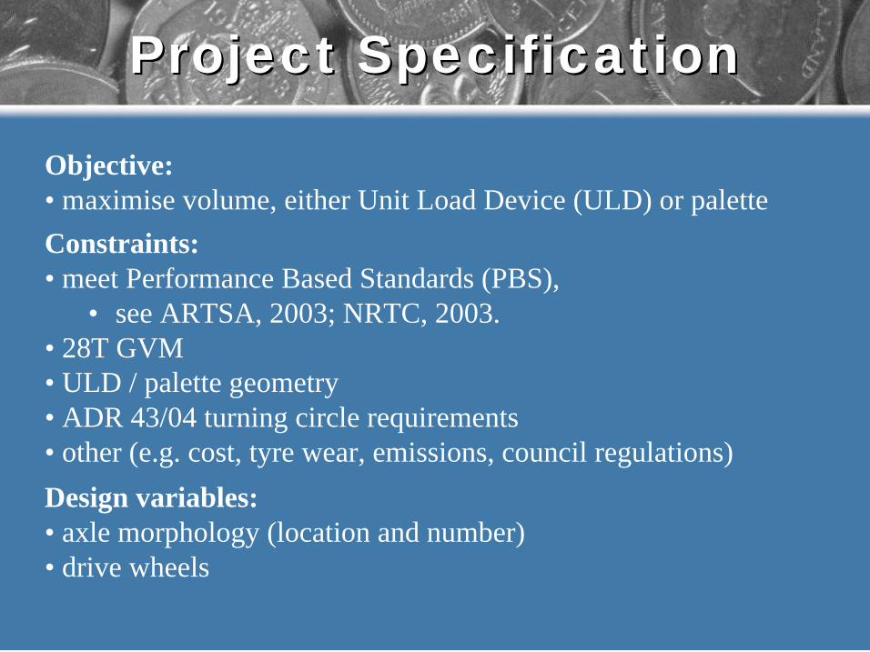
Project SpecificationProject Specification
Objective:
• maximise volume, either Unit Load Device (ULD) or palette
Constraints:
• meet Performance Based Standards (PBS),
• see ARTSA, 2003; NRTC, 2003.
• 28T GVM
• ULD / palette geometry
• ADR 43/04 turning circle requirements
• other (e.g. cost, tyre wear, emissions, council regulations)
Design variables:
• axle morphology (location and number)
• drive wheels
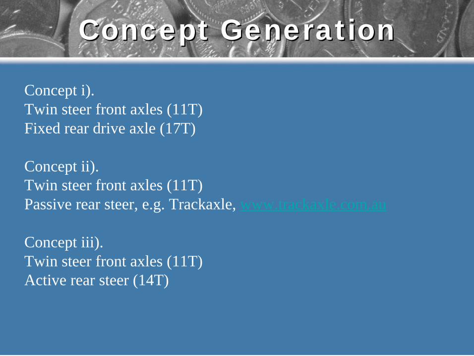
Concept GenerationConcept Generation
Concept i).
Twin steer front axles (11T)
Fixed rear drive axle (17T)
Concept ii).
Twin steer front axles (11T)
Passive rear steer, e.g. Trackaxle, www.trackaxle.com.au
Concept iii).
Twin steer front axles (11T)
Active rear steer (14T)
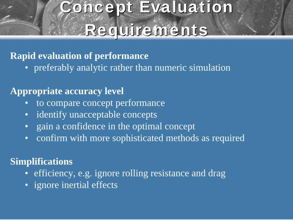
Concept EvaluationConcept Evaluation
RequirementsRequirements
Rapid evaluation of performance
• preferably analytic rather than numeric simulation
Appropriate accuracy level
• to compare concept performance
• identify unacceptable concepts
• gain a confidence in the optimal concept
• confirm with more sophisticated methods as required
Simplifications
• efficiency, e.g. ignore rolling resistance and drag
• ignore inertial effects

PBS Evaluation (1/5)PBS Evaluation (1/5)
PBS evaluation categories
• power transmission
• static loading
• low speed tracking
• high speed handling
Evaluation requirements
Performance measures Power
transmission
Static
loading
Low speed
manoeuvre
Transient
handling
1. Startability
2. Gradability
3. Acceleration
4. Overtaking provision
5. TASP
6. Low speed offtracking
7. Frontal swing
8. Tail swing
9. Steer tyre friction demand
10. Static rollover threshold
11. Rearward amplification
12. High -speed transient off tracking
13. Yaw damping
14. Pavement vertical loading
15. Pavement horizontal loading
16. Bridge loading
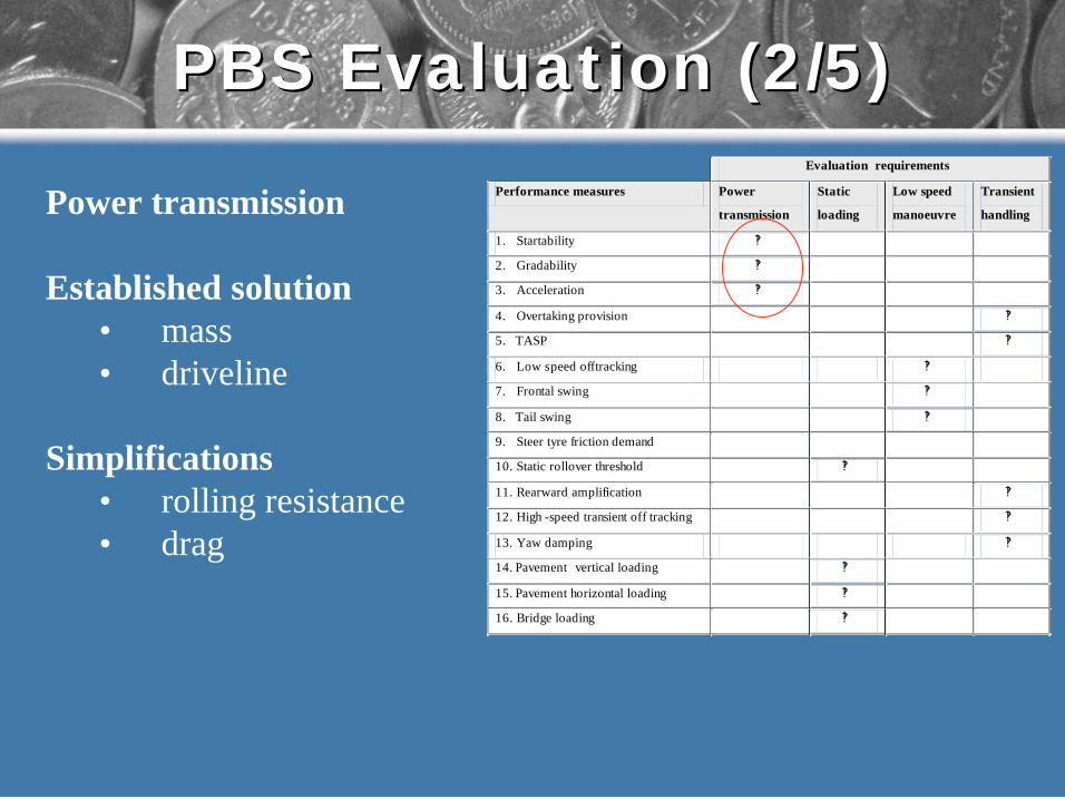
PBS Evaluation (2/5)PBS Evaluation (2/5)
Power transmission
Established solution
• mass
• driveline
Simplifications
• rolling resistance
• drag
Evaluation requirements
Performance measures Power
transmission
Static
loading
Low speed
manoeuvre
Transient
handling
1. Startability
2. Gradability
3. Acceleration
4. Overtaking provision
5. TASP
6. Low speed offtracking
7. Frontal swing
8. Tail swing
9. Steer tyre friction demand
10. Static rollover threshold
11. Rearward amplification
12. High -speed transient off tracking
13. Yaw damping
14. Pavement vertical loading
15. Pavement horizontal loading
16. Bridge loading

PBS Evaluation (3/5)PBS Evaluation (3/5)
Static loading
Established solution
• mass
• geometry
• axle conditions
Simplifications
• tyre contact
• bridge load
Static loading limits the allowable mass for a given axle configuration
Evaluation requirements
Performance measures Power
transmission
Static
loading
Low speed
manoeuvre
Transient
handling
1. Startability
2. Gradability
3. Acceleration
4. Overtaking provision
5. TASP
6. Low speed offtracking
7. Frontal swing
8. Tail swing
9. Steer tyre friction demand
10. Static rollover threshold
11. Rearward amplification
12. High -speed transient off tracking
13. Yaw damping
14. Pavement vertical loading
15. Pavement horizontal loading
16. Bridge loading
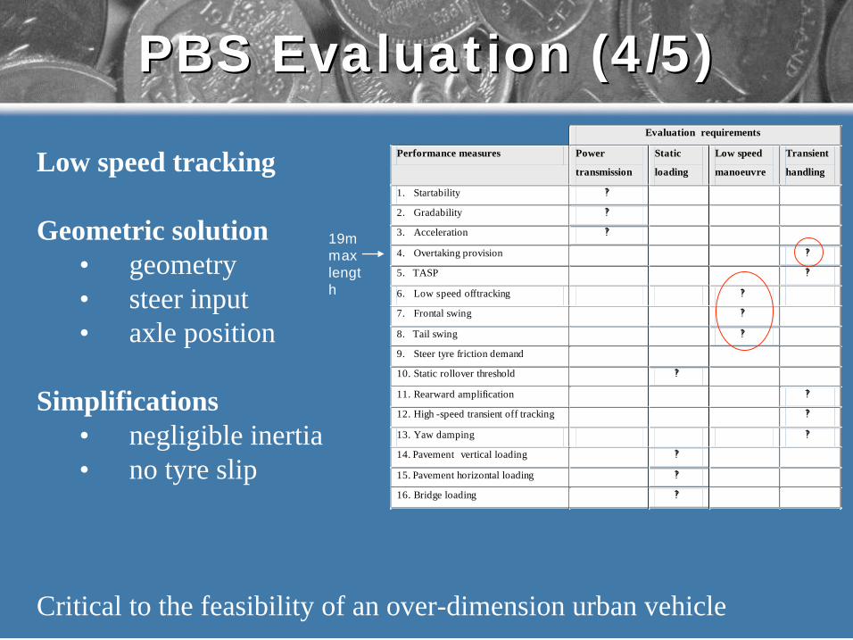
PBS Evaluation (4/5)PBS Evaluation (4/5)
Low speed tracking
Geometric solution
• geometry
• steer input
• axle position
Simplifications
• negligible inertia
• no tyre slip
Critical to the feasibility of an over-dimension urban vehicle
Evaluation requirements
Performance measures Power
transmission
Static
loading
Low speed
manoeuvre
Transient
handling
1. Startability
2. Gradability
3. Acceleration
4. Overtaking provision
5. TASP
6. Low speed offtracking
7. Frontal swing
8. Tail swing
9. Steer tyre friction demand
10. Static rollover threshold
11. Rearward amplification
12. High -speed transient off tracking
13. Yaw damping
14. Pavement vertical loading
15. Pavement horizontal loading
16. Bridge loading
19m
max
lengt
h
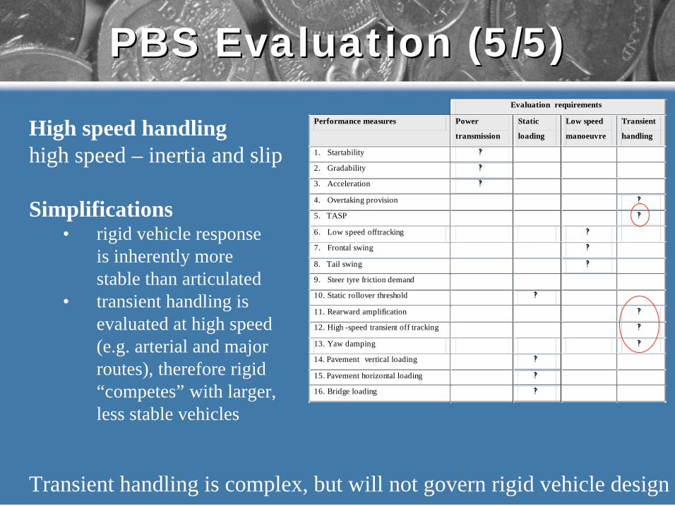
PBS Evaluation (5/5)PBS Evaluation (5/5)
High speed handling
high speed – inertia and slip
Simplifications• rigid vehicle response
is inherently more
stable than articulated
• transient handling is
evaluated at high speed
(e.g. arterial and major
routes), therefore rigid
“competes” with larger,
less stable vehicles
Transient handling is complex, but will not govern rigid vehicle design
Evaluation requirements
Performance measures Power
transmission
Static
loading
Low speed
manoeuvre
Transient
handling
1. Startability
2. Gradability
3. Acceleration
4. Overtaking provision
5. TASP
6. Low speed offtracking
7. Frontal swing
8. Tail swing
9. Steer tyre friction demand
10. Static rollover threshold
11. Rearward amplification
12. High -speed transient off tracking
13. Yaw damping
14. Pavement vertical loading
15. Pavement horizontal loading
16. Bridge loading
PBS Rigid Vehicle DesignPBS Rigid Vehicle Design
• The design of a PBS vehicle is governed by (NRTC, 2003):
• Low Speed Swept Path
• Frontal Swing
• Tail Swing
•Australian Vehicle Standards Rules (AVSR) must be met:
• e.g. ADR 43/04 “must have a turning circle …
not exceeding 25m”

Low Speed Swept PathLow Speed Swept Path
Low Speed Swept Path:
“Maximum distance that the rear axle tracks inside the
path taken of the steering axle in an 11.25m, 90º turn at
low speed”.
Performance standard:
Maximum Swept Path:
Level 1: 7.4 m
Level 1: 8.7 m
Level 1: 10.1m
Level 1: 13.7mSwept path in a 90° intersection turn (NRTC, 2003)
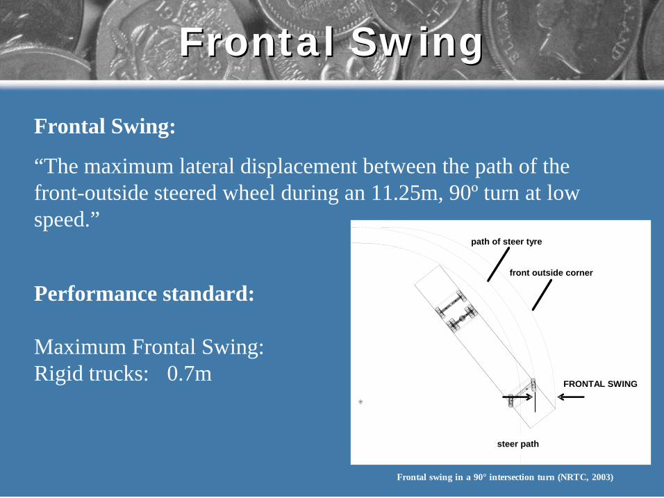
Frontal Swing:
“The maximum lateral displacement between the path of the
front-outside steered wheel during an 11.25m, 90º turn at low
speed.”
Performance standard:
Maximum Frontal Swing:
Rigid trucks: 0.7m
Frontal SwingFrontal Swing
FRONTAL SWING
steer path
front outside corner
path of steer tyre
Frontal swing in a 90° intersection turn (NRTC, 2003)

Tail SwingTail Swing
Tail swing:
“The maximum lateral distance that the outer rearmost point on
a vehicle moves outwards, during an 11.25m, 90º turn at low
speed”
Performance standard:
Maximum Tail Swing:
Level 1: 0.30 m
Level 2: 0.35 m
Level 3: 0.35 m
Level 4 : 0.50 m
TAIL SWING
Tail swing in a 90° intersection turn (NRTC,
2003)
ADR 43/04ADR 43/04
ADR 43/04 :
“Every vehicle must have a turning circle in either
direction, as determined by reference to the extreme
outer edge of the tyre track at ground level, not exceeding
25 metres in diameter.”
Performance standard:
Limit on maximum steer angle of the forward-inside wheel for
a given wheelbase.

Evaluating PerformanceEvaluating Performance
The performance measures of importance to rigid
vehicle design can be evaluated from the vehicle
Swept Path during two maneuvers:
Maneuver 1. PBS: prescribed 90 degree turn
Maneuver 2. ADR: prescribed 25m diameter turn
Analytic software was developed to rapidly assess the
Swept Path of a vehicle in these maneuvers.

Swept Path Analysis (PBS)Swept Path Analysis (PBS)
Maneuver 1. PBS: prescribed 90 degree turn
Swept Path Software rapidly
assesses the Low Speed
Swept Path, Frontal Swing
and Tail Swing for the
prescribed 90 degree turn
Outside front bumper
Front outside wheelOutside rear wheel
Tail swing in a 90° intersection turn (Leary and Burvill,
2003)

Swept Path Analysis (ADR)Swept Path Analysis (ADR)
Maneuver 2. ADR: prescribed 25m diameter turn
Steady state case:
Provides an initial estimate of
the required steering angle
based on steady state conditions:
857412
635310
48408
35296
23194
Inside wheel
(deg)
Outside wheel
(deg)
Wheel Base
(m)
Steady state turn geometry for a twin steer rigid vehicle
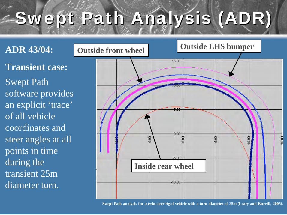
Swept Path Analysis (ADR)Swept Path Analysis (ADR)
ADR 43/04:
Transient case:
Swept Path
software provides
an explicit ‘trace’
of all vehicle
coordinates and
steer angles at all
points in time
during the
transient 25m
diameter turn.
Outside LHS bumper
Inside rear wheel
Swept Path analysis for a twin steer rigid vehicle with a turn diameter of 25m (Leary and Burvill, 2005).
Outside front wheel

Concept GenerationConcept Generation
Concept i).
Twin steer front axles (11T)
Fixed rear drive axle (17T)
Concept ii).
Twin steer front axles (11T)
Passive rear steer
(e.g Trackaxle type)
Concept iii).
Twin steer front axles (11T)
Active rear steer (14T)
Concept i).
Viable for Level 2 network access
Conditionally viable for Level 1
network access
Concept ii).
Viable for Level 1 network access
Reduced tyre wear
Increased rear overhang
Increased cost
Concept iii).
Conditionally as for Concept ii).
Significantly increased cost
ReferencesReferences
References:
• ARTSA (2003), PBS Explained: Performance Based Standards for
Road Transport Vehicles, Issue 1 September 2003, Australian Road
Transport Suppliers Association, Melbourne.
Available at www.artsa.com.au/PBS_Explained_Sept_03.pdf
• NRTC (2003), Performance-Based Standards Phase A – Standards
and Measures Regulatory Impact Statement, National Road
Transport Commission, December 2003, Australia.
• Leary and Burvill (2005), Performance Based Standards
Assessment of a Rigid Urban Transport Vehicle, ICED, Melbourne.
Available at www.sweptpath.com
2004 Technical & Maintenance2004 Technical & Maintenance
ConferenceConference
A High Productivity Urban Rigid Truck
Delivered Through
Performance Based Standards (PBS)
Martin Leary
PhD Candidate
University Of Melbourne