2004 S/T SMALL TRUCK AGE i - GM UPFITTER · S/T Small Truck 2004 2004 S/T SMALL TRUCK AGE 3 Section...
35
S/T Small Truck 2004 2004 S/T SMALL TRUCK i PAGE BODY BUILDERS INSTRUCTIONS ......................................................................................................................................................... 1 Section 0 – General Instructions ..................................................................................................................................................... 1 Section 1 – Body ................................................................................................................................................................................ 2 Air Conditioning .......................................................................................................................................................................... 2 Section 2 – Frame ............................................................................................................................................................................. 3 Flanges ....................................................................................................................................................................................... 3 Holes ........................................................................................................................................................................................... 3 Welding ....................................................................................................................................................................................... 3 Alterations ................................................................................................................................................................................... 4 Shear Plate Attachments ............................................................................................................................................................ 4 Section 3 – Front Suspension .......................................................................................................................................................... 4 Section 4 – Rear Suspension ........................................................................................................................................................... 5 Section 5 – Brakes ............................................................................................................................................................................ 5 Section 6 – Engine ............................................................................................................................................................................. 6 Section 7 – Transmission .................................................................................................................................................................. 7 Section 8 – Fuel and Exhaust ........................................................................................................................................................... 8 Fuel Systems .............................................................................................................................................................................. 8 Fuel Lines .................................................................................................................................................................................... 8 Fuel Tank ..................................................................................................................................................................................... 9 Exhaust System .......................................................................................................................................................................... 9 Section 9 – Steering ........................................................................................................................................................................ 10 Section 10 – Tires ............................................................................................................................................................................ 11 Section 12 – Electrical Battery and Battery Cables ..................................................................................................................... 11 Accessory Power Supply Feed: ................................................................................................................................................ 12 Section 13 – Cooling ....................................................................................................................................................................... 13
Transcript of 2004 S/T SMALL TRUCK AGE i - GM UPFITTER · S/T Small Truck 2004 2004 S/T SMALL TRUCK AGE 3 Section...

S/T Small Truck 2004
2004 S/T SMALL TRUCK iPA
GE
BODY BUILDERS INSTRUCTIONS ......................................................................................................................................................... 1
Section 0 – General Instructions ..................................................................................................................................................... 1
Section 1 – Body................................................................................................................................................................................ 2
Air Conditioning .......................................................................................................................................................................... 2
Section 2 – Frame ............................................................................................................................................................................. 3
Flanges ....................................................................................................................................................................................... 3
Holes ........................................................................................................................................................................................... 3
Welding ....................................................................................................................................................................................... 3
Alterations ................................................................................................................................................................................... 4
Shear Plate Attachments ............................................................................................................................................................ 4
Section 3 – Front Suspension .......................................................................................................................................................... 4
Section 4 – Rear Suspension ........................................................................................................................................................... 5
Section 5 – Brakes ............................................................................................................................................................................ 5
Section 6 – Engine............................................................................................................................................................................. 6
Section 7 – Transmission.................................................................................................................................................................. 7
Section 8 – Fuel and Exhaust ........................................................................................................................................................... 8
Fuel Systems .............................................................................................................................................................................. 8
Fuel Lines .................................................................................................................................................................................... 8
Fuel Tank ..................................................................................................................................................................................... 9
Exhaust System .......................................................................................................................................................................... 9
Section 9 – Steering ........................................................................................................................................................................ 10
Section 10 – Tires ............................................................................................................................................................................ 11
Section 12 – Electrical Battery and Battery Cables ..................................................................................................................... 11
Accessory Power Supply Feed: ................................................................................................................................................ 12
Section 13 – Cooling ....................................................................................................................................................................... 13

S/T Small Truck 2004
2004 S/T SMALL TRUCK iiPA
GE
CHASSIS
GENERAL CHASSIS ARRANGEMENT
Pickup, General Arrangement – T 10643 .............................................................................................................................. 14
BODY
EXTERIOR GENERAL ARRANGEMENT
Pickup, Crew Cab with Short Box – T 10643 ........................................................................................................................ 15
PICKUP CAB EXTERIOR
Crew Cab Exterior – T 10643.................................................................................................................................................. 16
Outside Mirror Options – T 10643 .......................................................................................................................................... 17
Door Swings – T 10643 ........................................................................................................................................................... 18
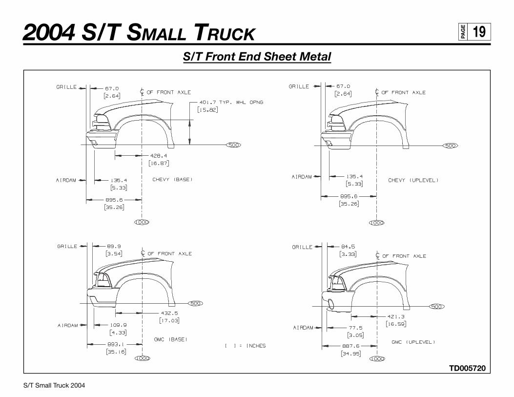
S/T Front End Sheet Metal ..................................................................................................................................................... 19
Cab Profile – T 10643 .............................................................................................................................................................. 20
PICKUP BOX
Pickup Box – T 10643.............................................................................................................................................................. 21
Pickup Box, Top Rail – T 10643 .............................................................................................................................................. 22
Pickup Box, Interior – T 10643 ............................................................................................................................................... 23
INTERIOR SEATING
Crew Cab, Interior – T 10643.................................................................................................................................................. 24
Interior Seating – T 10643....................................................................................................................................................... 25
FRAME
FRAME RAIL AND CROSSMEMBER ARRANGEMENT
Rail and Crossmember Arrangement – T 10643 w/Z85 ....................................................................................................... 26
SPARE TIRE CARRIER
Spare Tire Carrier – T 10643................................................................................................................................................... 27
AXLE/SUSPENSION
Front Axle / Tire Data Chart – T 10000 .......................................................................................................................................... 28

S/T Small Truck 2004
2004 S/T SMALL TRUCK iiiPA
GE
AXLE/SUSPENSION (Continued)
Pickup, Rear Axle / Tire Data Chart – S/T 10003.......................................................................................................................... 29
FUEL TANK
Fuel Tank – T 10643 ......................................................................................................................................................................... 30
EXHAUST
S/T Tail Pipe Locations ................................................................................................................................................................... 31
ELECTRICAL
Ordering Information ...................................................................................................................................................................... 32

S/T Small Truck 2004
2004 S/T SMALL TRUCK 1PA
GE
BODY BUILDERS INSTRUCTIONS
The Incomplete Vehicle Document (IVD) is supplied with each incomplete vehicle, and provides information that should be used byintermediate and final stage manufacturers in determining conformity to applicable Federal Motor Vehicle Safety Standards (FMVSS). TheIVD also includes information which must be followed in order to ensure that Environmental Protection Agency (EPA) andCalifornia emissions certification requirements and NHTSA Fuel Regulations are met.
The Body Builders Manual contains information that may be used in addition to the IVD for any manufacturer making alterations to a GMcomplete/incomplete vehicle. No alteration should be made to the incomplete vehicle which either directly or indirectly results in anycomponent, assembly or system being in nonconformance with any applicable Federal Motor Vehicle Safety Standard or EmissionRegulation. Intermediate and final stage manufacturers should be familiar with all Federal Motor Vehicle Safety Standards andEmission Regulations and aware of their specific responsibilities as manufacturers.
For further assistance contact Upfitter Integration at: 1 (800) 875-4742, or go to our Web site at “http://www.gmupfitter.com.”
Section 0 — General Instructions
Check for proper clearance between body members and chassis components which may in any way affect the reliability andperformance of the vehicle by developing abrasion and wear points from moving parts or degradation from extreme environment or thermalexposure or may increase interior noise.
Check headlamp aim and all vehicle illumination systems for proper operation when the vehicle has been completed. Re-aim headlampswhen necessary. Check for proper operation of windshield washer, wipers and defroster system.
Extreme care must be taken when working on vehicles equipped with Powertrain Control Module (PCM), Vehicle Control Module (VCM) orany electronic unit associated with an inflatable restraint system. (See Owner’s Manual).
If arc-welding is employed on the chassis, precautions must be taken to protect all vehicle components, especially brake, fuel lines and fueltank assembly, electrical wiring and ECM/PCM/TCM or VCM. To avoid electronic component damage, disconnect battery (batteries);disconnect the negative cable first, followed by the positive. To reconnect cables; connect the positive first, then the negative.
When welding components to the frame assembly, remove the wax coating in the area of the weld in order to obtain secure welds. Aftercompletion of the weld, a compatible corrosion protection should be applied to the affected weld areas.
All labels on the vehicle (any message applied to the vehicle or vehicle component that informs, instructs, or warns) must appear on thecompleted vehicle so the user can read them easily and without obstruction.
(Section 0 — continued on next page)

S/T Small Truck 2004
2004 S/T SMALL TRUCK 2PA
GE
(Section 0 — continued from previous page)
Service and service replacement parts for your add-on systems may not be available from a GM dealer. Those installing aftermarket systemsshould provide information as to where and how to obtain service.
Section 1 — Body
Body structures, interior and accessory arrangements must be designed into the vehicle to provide for proper load distribution on both axlesand not to exceed any gross axle weight ratings. Lateral load equalization must also be maintained. The resultant Center of Gravity of theunladen vehicle must be within the limits tabulated in the FMVSS 105 section of the Incomplete Vehicle Document.
Body insulation provided by General Motors should not be removed. This includes any thermal or underbody heat shields. This insulation isprovided to protect the vehicle body and occupants from excessive heat and/or provide noise attenuation. Any replacement material internalto the occupant compartment must be certified for MVSS standard on flammability. Areas of specific concern, but not limited to, are:
• Underbody exhaust, muffler and tail pipe shields and insulators.
• Rear load floor interior insulation.
• Front floor interior insulation.
• Dash mat insulation.
• Engine cowl insulation – interior and exterior.
• Engine cover insulation.
If body builder installs seating other than that supplied with vehicle, it is the body builder’s responsibility to ensure that the seating andrestraint systems comply with FMVSS requirements. The restraint systems supplied with the vehicle were designed to accommodate theseating reference points and seat travel of the original equipment seats only.
Air Conditioning
For additional information refer to Engine – Section 6.
NOTE: Air conditioning systems using R-134A refrigerant are equipped with metric fittings to prevent interchange with R-12 refrigerantcomponents. Do not interchange R-134A components, refrigerant oil or service equipment with R-12 components, refrigerant oil orservice equipment.

S/T Small Truck 2004
2004 S/T SMALL TRUCK 3PA
GE
Section 2 — Frame
Hole drilling, welding, modifications, or alterations to the frame assembly are the responsibility of persons performing these operations.These same individuals assume complete responsibility for frame assembly reliability, performance after alterations and compliance toapplicable FMVSS requirements.
The following procedures and specific precautionary instructions are recommended for proper installation of special bodies and/orequipment on GM frames. Failure to follow these recommendations could result in serious damage to the basic vehicle.
Flanges
Do not drill holes in frame flanges.
Holes
Holes to mount brackets, supports, and out-riggers must be drilled in the vertical side rail web with the following restrictions:
• Material between edge of hole and inside of upper or lower flange must not be less than 37 mm (1.50 in.) for low carbon steel(36,000 PSI yield).
• The minimum edge distance between any two (2) holes must be larger than twice the diameter of the larger hole.
• No holes should exceed 20 mm (0.75 in.) in diameter.
• All holes should be drilled in the frame using appropriate drilling practice and safety precautions.
Welding
CAUTION: Fuel tank and fuel lines must be drained and all vapors purged to ensure noncombustible mixture before any welding, brazing orsoldering.
When welding low carbon steel side rails, crossmembers and brackets (32,000 or 36,000 PSI yield strength), emphasis is placed upon weldapplication techniques to avoid stress risers that may adversely affect frame operating stresses.
When welding is performed anywhere on the vehicle, precautionary measures should be taken to prevent damage to electricalsystem wiring or components. Prior to any welding, parts or components which could be damaged by excessive temperatures must beremoved or adequately shielded; the battery cables should be disconnected at the battery. Also prior to welding, the area to be welded andsurrounding area must be cleaned of all frame protective coating. After welding, when parts are cool, carefully inspect wiring and electrical
(Section 2 — continued on next page)

S/T Small Truck 2004
2004 S/T SMALL TRUCK 4PA
GE
(Section 2 — continued from previous page)
components for shorts or other damage which could draw excessive currents and possibly cause an electrical system short when thebattery is reconnected. Apply protective coating to areas where coating was removed.
Alterations
If the wheelbase is modified the alterer must take responsibility for compliance with affected motor vehicle safety standards and for warrantyon items such as driveshafts, universal joints, center bearings and rear transmission tailshaft, transfer case and transmission case fractures,output shaft bushings, bearings, brakes, fuel systems and any other related component failures. Additionally, the customer must be alertedin the modifier’s owner’s manual that parts for the reworked area are not available through the General Motors service parts system.
Shear Plate Attachments
Attachments of shear plates should be accomplished by using existing manufacturing holes already available in the frame side rails. Manu-facturing holes, normally 16 mm in diameter, are consistently placed along the frame side member in the center of the web on each frame.
When additional holes are required for shear plate attachment, they should be no larger than 20 mm (0.75 in.) in diameter. Holes are to bedrilled no closer than 63.5 mm (2.5 in.) apart. For holes drilled forward of the rear axle, centers are to be no closer than 63.5 mm (2.5 in.) fromthe top or bottom flanges and no closer than 89 mm (3.5 in.) from any suspension attachments. For frame holes drilled rearward of the rearaxle, hole centers are to be no closer than 51 mm (2.0 in.) from the top or bottom flange and no closer than 89 mm (3.5 in.) from suspensionattachments.
No additional holes or notching of either top or bottom frame flanges is allowed.
Rear bodies or platforms added to the vehicle must utilize the released attachment points used by the pick-up box, along withfasteners of the same diameter. These are minimum requirements; additional fasteners are permissible.
Section 3 — Front Suspension
See chassis data information for clearances and assistance in calculating trim heights.
Since there is a large variation in completed vehicle front weight due to differences in body weight and equipment, the frontsuspension alignment must be checked and reset if necessary after the vehicle is completed. Caster and camber should be set withreference to the “A” dimensions.
See Truck Service Manual for complete alignment procedure, specifications and measurement of the “A” dimension under “Diagnosis andFront Alignment” section.

S/T Small Truck 2004
2004 S/T SMALL TRUCK 5PA
GE
Section 4 — Rear Suspension
Clearance to body should be provided for the suspension, axle, driveshaft and tires under the following conditions: (1) Axle in full jounceagainst the metal-to-metal stop, (2) Axle at 4.5˚ roll with one side of axle in full jounce at the metal-to-metal stop and (3) Axle at designposition. Allowance for the tire chain clearance shown on a maximum grown tire must allow for (1.66 in.) clearance to the sides of the tire and(2.5 in.) to the top of the tire. Be sure sufficient clearance is provided for suspension, axle and tire and wheel in full vertical travel (up anddown).
NOTE: Notification to the consumer may be required in certain states if tire chains cannot be used.
Pipes, wiring, conduits and any other related components must not be placed where they cross the path of motion of the rear axle,driveshaft, axle brake pipes, hoses, spring or tires. Such crossing could result in rupture, wear through, or separation due to normal axlemotion.
See chassis data information for additional clearances and for assistance in calculating trim heights.
Section 5 — Brakes
See Truck Service Manual for brake specifications.
Due to the critical nature of brake systems, anyone making modifications or alterations must assume complete responsibility forsystem reliability, performance and certification to FMVSS 105 or FMVSS 121.
It is mandatory that no change be made to the brake main cylinder location, brake pedal push rod length or pedal position.
Ensure that hydraulic brake system is free of air and hydraulic leaks. Bleed brakes if required, following procedures as outlined in truckchassis service manual. Ensure that vacuum booster system or hydroboost system is functional and free of leaks.
Check master cylinder fluid level and fill as necessary. (Refer to Owner’s Manual).
Check power steering fluid level for models equipped with hydroboost brake. (Refer to Owner’s Manual).
Added floor covering or carpeting must not restrict service or parking brake pedal travel from released position to full pedal travel.
No body part or chassis-mounted component may be located within 2.0 in. of brake hose routing in all wheel and axle positions. All exhaustsystem components must also have a minimum of 2.0 in. clearance to brake hoses in closest positions. (Be sure to account for brake hosetravel with suspension).
(Section 5 — continued on next page)
S/T Small Truck 2004
2004 S/T SMALL TRUCK 6PA
GE
(Section 5 — continued from previous page)
Body builder is to verify that the brake warning switch is operative. The brake warning switch on models equipped with vacuum-hydraulicbrakes is located adjacent to the master cylinder vacuum unit. This includes both the brake system differential pressure and parking brakeactuator switch.
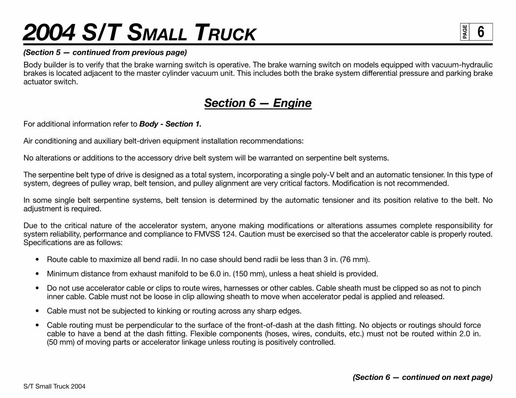
Section 6 — Engine
For additional information refer to Body - Section 1.
Air conditioning and auxiliary belt-driven equipment installation recommendations:
No alterations or additions to the accessory drive belt system will be warranted on serpentine belt systems.
The serpentine belt type of drive is designed as a total system, incorporating a single poly-V belt and an automatic tensioner. In this type ofsystem, degrees of pulley wrap, belt tension, and pulley alignment are very critical factors. Modification is not recommended.
In some single belt serpentine systems, belt tension is determined by the automatic tensioner and its position relative to the belt. Noadjustment is required.
Due to the critical nature of the accelerator system, anyone making modifications or alterations assumes complete responsibility forsystem reliability, performance and compliance to FMVSS 124. Caution must be exercised so that the accelerator cable is properly routed.Specifications are as follows:
• Route cable to maximize all bend radii. In no case should bend radii be less than 3 in. (76 mm).
• Minimum distance from exhaust manifold to be 6.0 in. (150 mm), unless a heat shield is provided.
• Do not use accelerator cable or clips to route wires, harnesses or other cables. Cable sheath must be clipped so as not to pinchinner cable. Cable must not be loose in clip allowing sheath to move when accelerator pedal is applied and released.
• Cable must not be subjected to kinking or routing across any sharp edges.
• Cable routing must be perpendicular to the surface of the front-of-dash at the dash fitting. No objects or routings should forcecable to have a bend at the dash fitting. Flexible components (hoses, wires, conduits, etc.) must not be routed within 2.0 in.(50 mm) of moving parts or accelerator linkage unless routing is positively controlled.
(Section 6 — continued on next page)

S/T Small Truck 2004
2004 S/T SMALL TRUCK 7PA
GE
(Section 6 — continued from previous page)
• Caution must be taken so that the accelerator pedal remains properly located. Guidelines for accelerator pedal locations are asfollows:
— Ensure that the accelerator can freely operate from idle to wide-open throttle position and return. Make sure that the pedal willnot hang up on any nearby items such as carpets, floor, screws, wiring harnesses, etc. Engine cover should have at least oneinch (25 mm) clearance to side of accelerator pedal with the carpet mat installed.
— Accelerator to brake pedal relationship has been designed to provide minimum driver movement and should not be altered inany way.
Gasoline engine induction and/or ignition system is certified in compliance with the Federal Vehicle Emission Standards. Any alterations tothe systems or components could void compliance and render the vehicle illegal. System includes:
• Fuel system – throttle body and port fuel injection (PFI) or sequential central port injector (SCPI) and associated tubes, hoses andpipes, air cleaner outside air hose, mass air flow sensor, fuel pump and inlet manifold, fuel vapor canister.
• Exhaust system.
• Ignition system distributor and initial spark timing setting, spark plugs, spark plug wires.
• Crankcase ventilation system.
Section 7 — Transmission
Light duty models equipped with manual transmission have a clutch-operated start safety switch. Starter should operate whenever theignition is turned to start and the clutch is fully depressed. Readjust if necessary as outlined in the Truck Service Manual.
Models equipped with automatic transmissions have a steering column mounted or a transmission mounted neutral/park start safetymechanical lockout feature, which interfaces with the steering column ignition switch. Starter should operate only when gear shift lever is inneutral or park position. Readjust the shift linkage or neutral start backup switch if necessary as outlined in the Truck Service Manual.
Models equipped with manual transmission use a hydraulic clutch actuator. Check fluid level as outlined in the vehicle owner’s manual.
It is mandatory that no change be made to the clutch master cylinder location, clutch master or slave cylinder push rod length, or pedalposition.

S/T Small Truck 2004
2004 S/T SMALL TRUCK 8PA
GE
S/T 1003 Pickup, General Arrangement
Section 8 — Fuel and Exhaust
Fuel Systems
Due to the critical nature of sealing the fuel system, anyone making modifications or alterations to the existing system must assumecomplete responsibility for the system reliability, performance and compliance to FMVSS 301.
The fuel evaporative emission control equipment is certified to be in compliance with the Federal and California Vehicle Emission Standards.Any alterations to systems or components and their location could void compliance. System includes:
• Fuel tank, metering unit, lines including purge control solenoids and canister or canisters.
For these reasons, NO ALTERATION OF THE FUEL SYSTEM IS RECOMMENDED.
Fuel Lines
Fuel line routing precautions:
• 12 in. minimum clearance to exhaust system is required or a metal shield must be provided.
• Fuel lines should be clipped to chassis to prevent chafing. Metal clips must have rubber or plastic liners.
• Use corrosion resistant steel tubing with short sections of approved hose to connect components. Hose-to-tube connectionsshould be clamped for diesel systems. Steel tube ends should be beaded for hose retention. Fuel supply is pressurized byan in-tank pump for PFI and SCPI systems. Coupled hose or nylon quick-connects must be used. Clamped hose is not accept-able for PFI and SCPI systems.
All engines require a fuel return system which returns excess fuel from the injection pump and injector nozzles back to fuel tanks. Careshould be taken that these lines are not blocked nor their hoses pinched. The engine may run poorly or stall if these lines are restricted orblocked.
All gasoline engine vehicles are equipped with fuel evaporative emission control equipment which is certified to be in compliance with theFederal or applicable California vehicle emission standards. Alterations to fuel tank and metering unit, lines, canister or canisters, canisterfilters, canister purge control valves, relay switches, tank auxiliary vent valve, engine speed controller, or other devices/systems aretherefore not allowable since vehicle adherence to C.A.R.B. and Federal regulations may be affected.
Diesel powered vehicles incorporate water drain provisions in the fuel system. These valves are only to be opened when siphoning water andcontaminants from the fuel system.
(Section 8 — continued on next page)

S/T Small Truck 2004
2004 S/T SMALL TRUCK 9PA
GE
S/T 10516—2 Door Utility, General Arrangement
(Section 8 — continued from previous page)
Fuel Tank
For vehicles with full frames, the tank must have a minimum clearance of 2 in. top, front, rear and sides to body and other supports.
Tank may be pressurized to 1.25 PSI maximum to check for final line leakage or for forcing fuel through the system. Pressures greater thanthis amount may be detrimental and affect tank durability.
The use of auxiliary fuel tanks is not recommended. If an auxiliary fuel tank is added, the alterer must take responsibility for compliancewith affected motor vehicle safety standards. Also, if an auxiliary fuel tank is added to a gasoline-powered vehicle, the fuel must be drawnthrough a pipe at the top of the tank (balance line between tanks is not permitted).
Gasoline fueled vehicles are now equipped with a fuel pump return line. If an auxiliary tank is added, the tank selector valve must include areturn port which returns fuel to the tank from which the fuel is being drawn.
In gasoline engines the fuel pump is located in the fuel tank. The battery must be disconnected before starting any work on the fuel system.
In the use of dual fuel systems, the vehicle operator should strictly adhere to the manufacturer’s procedures for switching from gasoline togaseous fuel operation. Improper switching procedures may result in overheating and damage to the exhaust system and the vehicle. Thegaseous fuel tank should not be mounted in an enclosed area of the vehicle, such as the passenger compartment, trunk, etc., and thesystem should be vented to the outside of the vehicle. In addition, vehicles converted to gaseous fuels should not be stored inenclosed places such as garages. Further, General Motors cautions purchasers that the design, location and installation of any type of fuelstorage system involves significant technical and engineering considerations and that these statements on gaseous fuel conversions shouldnot be interpreted to be an approval by General Motors of any modification to the original equipment fuel system.
Conversions to gaseous fuel should be made in conformance with applicable Federal and State regulations. Removal of emission-controlcomponents, or the addition of gaseous fuel systems which could damage or reduce the longevity of those components and could alsocause the mechanical and emission performance warranty to be voided.
Exhaust System
Particular care should be taken to prevent the possibility of exhaust fumes and carbon monoxide exposure to vehicle occupants in unitscompleted by body builders. Holes and openings through the floor and alI other parts of the body must be permanently and adequatelysealed by the body builder to avoid exhaust intrusion into any occupant area. If it is necessary to change the exhaust outlet location, theexhaust discharge must be unobstructed and directed away from occupant areas. Alteration of the exhaust outlet or its position mayincrease exhaust noise and render the vehicle illegal in those areas with pass-by noise regulations. All vehicles > 10,000 lbs. GVWR comeunder Federal noise regulations, vehicles: < 10,000 lbs. GVWR are regulated by various state and local regulations of the EnvironmentalProtection Agency; see those regulations for rules, test procedure and noise levels permitted.
(Section 8 — continued on next page)

S/T Small Truck 2004
2004 S/T SMALL TRUCK 10PA
GE
S/T 10506–4 Door Utility, General Arrangement
(Section 8 — continued from previous page)
Tail pipe outlet location must be tested statically and with the vehicle in motion to ensure that exhaust gases do not penetrate side or rearwindows or underbody seams and holes. Auxiliary power plants should also be tested under the same conditions. Tail pipe exit ahead of rearwheels is not recommended.
Check for leaks in exhaust systems and repair as required.
Any exhaust joint which has been disassembled must have the exhaust gasket replaced and the fasteners torqued to specifications.Re-check exhaust system for leaks.
Exhaust temperatures can exceed 1600ºF under extreme operating conditions, with pipe surface temperatures slightly less than this.Extreme care must be used when placing body components in the proximity of the exhaust system so as not to exceed the ratedtemperature limits of the components. Due to variants in underbody configurations of the vehicles, we are not in a position to makerecommendations on how to insulate or design components in the proximity of the exhaust system.
Each manufacturer must make temperature checks of critical areas of his vehicle and adjust his design accordingly, or provide shielding toensure safe operation of his body components.
The same can be said for the engine compartment. Obviously there will be additional heat radiated from the engine. How much is retainedin the area will depend on how well this area is ventilated in your individual designs. Here again, temperature checks ofinterior areas surrounding the engine should be made to determine if your insulation is adequate. This is the same engineering practice wehave followed on our complete vehicles incorporating these exhaust systems.
Exhaust system materials are selected and tested to withstand the operating environment of the vehicle. Do not modify the exhaustsystem in any way. The tail pipes are made of 409 aluminized stainless steel.
Heatshields are mounted to the underbody and/or exhaust system components (catalytic converter, muffler and tail pipe). Shields for thepropshaft hanger bearings are also provided in some vehicles.
Section 9 — Steering
Check power steering fluid level and system operations. (Refer to Owner’s Manual).
The power steering hydraulic system should not be used to drive any other accessories.
Steering wheel and horn pad must not be altered or replaced.
The steering column mast jacket must not be altered.

S/T Small Truck 2004 – Revised – 06/2009
2004 S/T SMALL TRUCK 11EG
AP
PICKUP WEIGHT DISTRUBUTION
Section 10 — Tires
Check wheel lug nuts for proper torque; specifications are provided in the Owner’s Manual.
Substitution of tires of greater capacity than those offered as original equipment by vehicle manufacturer is not approved for use on originalequipment wheels. Any usage of higher capacity tires must be accompanied by higher capacity wheels. However, the wheel offset anddistance from centerline of rim to wheel mounting face must be the same as the replaced original equipment wheel to ensure proper wheelbearing loading and clearance of tires to body and chassis components.
Increasing tire and wheel capacity does not necessarily increase vehicle GVW ratings. It is recommended that tire chain clearance guideline,J683, from the Society of Automotive Engineers be adhered to in designing rear wheelhouse clearance.
Check tires and inflate to recommended tire pressure according to the tire pressure information provided in Owner’s Manual and tire inflationlabel provided with vehicle.
Any substitution of tires may affect Speedometer/Odometer accuracy.
Section 12 — Electrical Battery and Battery Cables
The vehicle battery should be located and positioned to make use of the existing battery cables. If the battery requires relocation and longercables are required, a proportionately larger gauge wire must be used. If in relocating the battery the negative ground cable is attached toframe rail, a cable of similar gauge be provided between the frame rail and the engine. This is required due to the heavy electrical loadsimposed by the starting circuit. To ensure proper operation of the battery cables the following chart on length, gauge and materials must bestrictly adhered to:
Combined length of positive and negative)reppoC( sehcnI ni elbaCeguaG elbaC
4
2 107
170
If the battery is remotely mounted (other than in the engine compartment) the ‘sense’ circuit in the generator regulator shall be used. Thesense circuit consists of a 7.76 OHM 1/4 watt resistor connected in series between the ‘S’ terminal of the generator and the B+ terminal ofthe battery.
(Section 12 — continued on next page)
0
66
S/T Small Truck 2004
2004 S/T SMALL TRUCK 12PA
GE
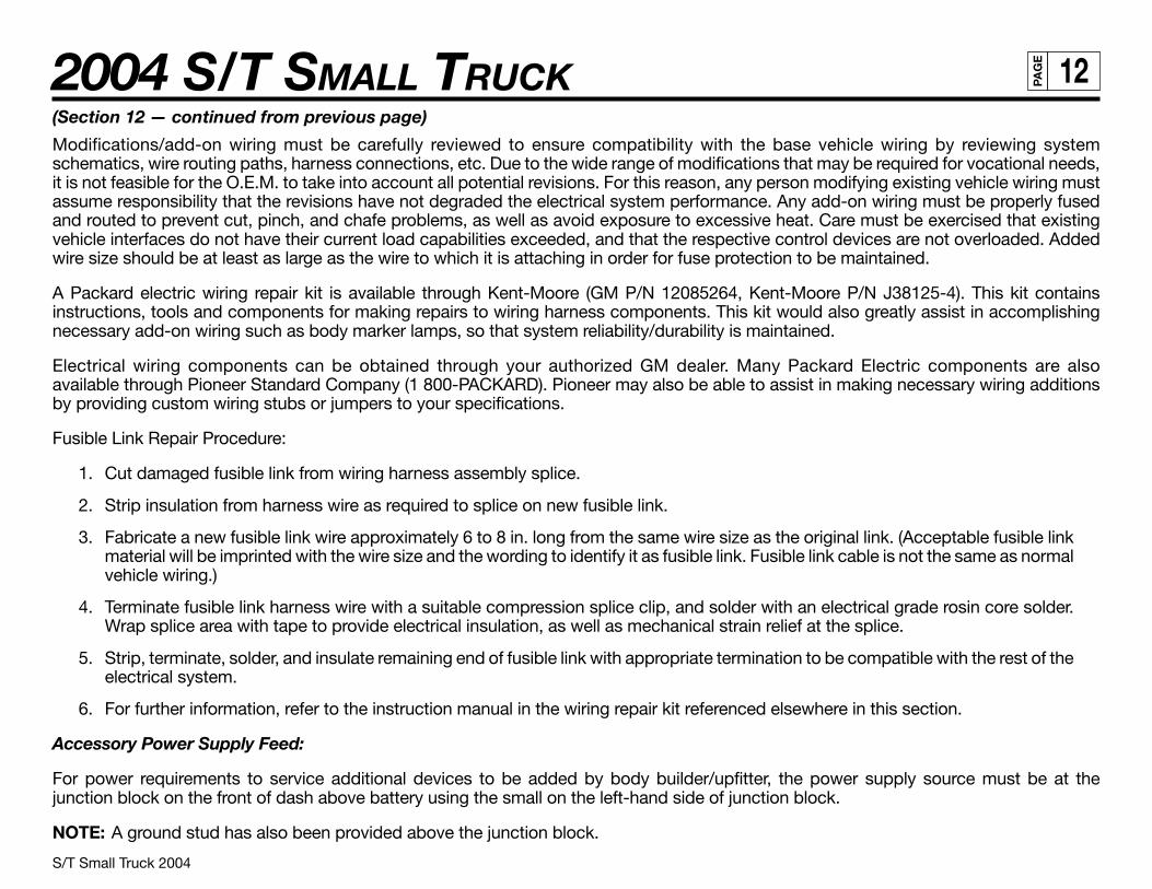
(Section 12 — continued from previous page)
Modifications/add-on wiring must be carefully reviewed to ensure compatibility with the base vehicle wiring by reviewing systemschematics, wire routing paths, harness connections, etc. Due to the wide range of modifications that may be required for vocational needs,it is not feasible for the O.E.M. to take into account all potential revisions. For this reason, any person modifying existing vehicle wiring mustassume responsibility that the revisions have not degraded the electrical system performance. Any add-on wiring must be properly fusedand routed to prevent cut, pinch, and chafe problems, as well as avoid exposure to excessive heat. Care must be exercised that existingvehicle interfaces do not have their current load capabilities exceeded, and that the respective control devices are not overloaded. Addedwire size should be at least as large as the wire to which it is attaching in order for fuse protection to be maintained.
A Packard electric wiring repair kit is available through Kent-Moore (GM P/N 12085264, Kent-Moore P/N J38125-4). This kit containsinstructions, tools and components for making repairs to wiring harness components. This kit would also greatly assist in accomplishingnecessary add-on wiring such as body marker lamps, so that system reliability/durability is maintained.
Electrical wiring components can be obtained through your authorized GM dealer. Many Packard Electric components are alsoavailable through Pioneer Standard Company (1 800-PACKARD). Pioneer may also be able to assist in making necessary wiring additionsby providing custom wiring stubs or jumpers to your specifications.
Fusible Link Repair Procedure:
1. Cut damaged fusible link from wiring harness assembly splice.
2. Strip insulation from harness wire as required to splice on new fusible link.
3. Fabricate a new fusible link wire approximately 6 to 8 in. long from the same wire size as the original link. (Acceptable fusible linkmaterial will be imprinted with the wire size and the wording to identify it as fusible link. Fusible link cable is not the same as normalvehicle wiring.)
4. Terminate fusible link harness wire with a suitable compression splice clip, and solder with an electrical grade rosin core solder.Wrap splice area with tape to provide electrical insulation, as well as mechanical strain relief at the splice.
5. Strip, terminate, solder, and insulate remaining end of fusible link with appropriate termination to be compatible with the rest of theelectrical system.
6. For further information, refer to the instruction manual in the wiring repair kit referenced elsewhere in this section.
Accessory Power Supply Feed:
For power requirements to service additional devices to be added by body builder/upfitter, the power supply source must be at thejunction block on the front of dash above battery using the small on the left-hand side of junction block.
NOTE: A ground stud has also been provided above the junction block.

S/T Small Truck 2004
2004 S/T SMALL TRUCK 13PA
GE
S/T 10603 Pickup, Regular Cab with Short Box. Hi-Wider, General Arrangement
Section 13 — Cooling
To provide satisfactory engine cooling, the following conditions must be met:
1. Do not locate any large objects in front of the radiator core or grille such as batteries, spare tires, lights/sirens, etc. They restrict airflow into the radiator core and influence fan blade stress.
2. Grille opening, size configuration and the external baffles provided should not be altered in any manner. Any reduction in coolingability may adversely affect engine/transmission performance.
3. Fan clutches not conforming to the original equipment specifications may not operate correctly and may stay “on” continuously,never come on, or cycle on and off excessively. This will result in a reduction of fuel economy, engine overheat at times, andannoying cycling respectively.
4. Continuous coolant flow is necessary from heater connection on engine-to-heater connection on radiator to control transmissionoil temperatures during closed thermostat (warm-up) operation. Do not alter this flow as it may result in premature engine ortransmission failure.
5. If a heater unit is not installed in the vehicle or a heater shut-off-valve is required, a line connecting the heater connection on theengine to the heater connection on the radiator must be installed. When a shut-off valve is required in heating system, it must beteed into the system in such a manner as to maintain continuous flow between engine heater connection-radiator heater connec-tion at all times.
6. Use GM 6277M Long Life Coolant only.
Do not install any internal flow restrictors.
• Heater hose: 3-way or 4-way valves must be used to provide constant water flow through the intake manifold pad area.
• If in-line shut-off valve is used in combination with 3-way valves, shut-off valve must not be closed until 3-way valve at engineis in the proper position.
Valve Sources
3Red-White Valve Corp., Carson, CA (213) 549-1010
Ranco Controls Div., Delaware, OH (614) 876-8022
4 Ranco Controls Div., Delaware, OH (614) 876-8022
Be sure to add coolant to system after adding capacity to system (heaters).

S/T Small Truck 2004
2004 S/T SMALL TRUCK 14PA
GE
S/T 10003 Pickup, General Arrangement
T 10643 Pickup, General Arrangement
TD005119

S/T Small Truck 2004
2004 S/T SMALL TRUCK 15PA
GE
TD005743
T 10643 Pickup, Crew Cab with Short Box

S/T Small Truck 2004
2004 S/T SMALL TRUCK 16PA
GE
TD005721
T 10643 Crew Cab Exterior

S/T Small Truck 2004
2004 S/T SMALL TRUCK 17PA
GE
TD005723
T 10643 Outside Mirror Options

S/T Small Truck 2004
2004 S/T SMALL TRUCK 18PA
GE
TD005722
T 10643 Door Swings
S/T Small Truck 2004
2004 S/T SMALL TRUCK 19PA
GE
TD005720
S/T Front End Sheet Metal

S/T Small Truck 2004
2004 S/T SMALL TRUCK 20PA
GE
TD005724
T 10643 Cab Profile

S/T Small Truck 2004
2004 S/T SMALL TRUCK 21PA
GE
TD005725
T 10643 Pickup Box

S/T Small Truck 2004
2004 S/T SMALL TRUCK 22PA
GE
TD005726
T 10643 Pickup Box, Top Rail

S/T Small Truck 2004
2004 S/T SMALL TRUCK 23PA
GE
TD005727
T 10643 Pickup Box, Interior

S/T Small Truck 2004
2004 S/T SMALL TRUCK 24PA
GE
TD005739
T 10643 Crew Cab, Interior

S/T Small Truck 2004
2004 S/T SMALL TRUCK 25PA
GE
TD005729
T 10643 Interior Seating

S/T Small Truck 2004
2004 S/T SMALL TRUCK 26PA
GE
T 10643 w/Z85 Rail and Crossmember Arrangement
TD005960f

S/T Small Truck 2004
2004 S/T SMALL TRUCK 27PA
GE
TD005731
T 10643 Spare Tire Carrier

S/T Small Truck 2004
2004 S/T SMALL TRUCK 28PA
GE
TD005813
T 10000 Front Axle / Tire Data Chart

S/T Small Truck 2004
2004 S/T SMALL TRUCK 29PA
GE
TD005814
S/T 10003 Pickup, Rear Axle / Tire Data Chart

S/T Small Truck 2004
2004 S/T SMALL TRUCK 30PA
GE
T 10643 Fuel Tank
TD005957c

S/T Small Truck 2004
2004 S/T SMALL TRUCK 31PA
GE
TD005736
S/T Tail Pipe Locations

S/T Small Truck 2004
2004 S/T SMALL TRUCK 32PA
GE
Ordering Information
Electrical diagrams are available from Chevrolet and GMC through service publications. They have contracted the following companies tohandle the ordering and shipping of the manuals.
Helm Inc.P.O. Box 07130Detroit, Michigan 48207
1 (313) 865-5000 for information and inquiries1 (800) 782-4356 for credit card orders
Routine orders will be shipped within 10 days of receipt. Rush orders will be accommodated for an additional charge.
Order forms are available upon request and orders can be paid by check or money order, made payable to the mentioned companies. CreditCard orders can be made by phone on the listed toll free phone numbers.