2004 CHECKING FOR DIAGNOSTIC TROUBLE CODES 2 · 2004 Touring: Instruments 2-3 HOME CODE TYPES There...
48
2004 Touring: Instruments 2-1 HOME 2004 CHECKING FOR DIAGNOSTIC TROUBLE CODES 2.1 CHECK ENGINE LAMP To diagnose electronic control module (ECM) or ignition con- trol module (ICM) system problems, start by observing the behavior of the check engine lamp. NOTES ● See Figure 2-2. “Key ON” means that the ignition key is turned to ON and the engine stop switch is set to RUN (although the engine is not running). ● When the ignition switch is turned ON, the check engine lamp will illuminate for approximately four seconds and then turn off. ● If the check engine lamp is not illuminated at Key ON. See 2.2 INITIAL DIAGNOSTIC CHECK: SPEEDOME- TER. ● If the check engine lamp comes on late (after 20 sec- onds). See 2.2 INITIAL DIAGNOSTIC CHECK: SPEED- OMETER. ● If the check engine lamp fails to turn OFF after the initial four second period. See 2.2 INITIAL DIAGNOSTIC CHECK: SPEEDOMETER. 1. See Figure 2-3. After lamp turns off after being illumi- nated for the first four second period, one of three situa- tions may occur. a. The lamp remains off. This indicates there are no current fault conditions or stored diagnostic trouble codes (DTC) currently detected by the ignition con- trol module (ICM) or electronic control module (ECM). b. The lamp stays off for only four seconds and then comes back on for an eight second period. This indi- cates an diagnostic trouble code is stored, but no current diagnostic trouble code exists. c. If the lamp remains on beyond the eight second period, then a current diagnostic trouble code exists. 2. See CODE TYPES which follows for a complete descrip- tion of diagnostic trouble code formats. NOTES Some diagnostic trouble codes can only be fully diagnosed during actuation. For example, a problem with the ignition coil will be considered a current fault even after the problem is corrected, since the ECM/ICM will not know of its resolution until after the coil is exercised by vehicle start sequence. In this manner, there may sometimes be a false indication of the current diagnostic trouble code. Figure 2-2. Ignition Switch (FLTR, FLHT/C/U) Figure 2-1. Speedometer f1240x2x 0 10 30 20 50 40 110 120 60 70 80 90 100 0 20 30 40 50 10 MPH H A R L E Y -D A V I D S O N C E R T IF I E D RPM x100 H A R L E Y -D A V I D S O N f2160x8x Check Engine Lamp 2
Transcript of 2004 CHECKING FOR DIAGNOSTIC TROUBLE CODES 2 · 2004 Touring: Instruments 2-3 HOME CODE TYPES There...
HOME
2
2004 CHECKING FOR DIAGNOSTIC TROUBLE CODES 2.1
CHECK ENGINE LAMP
To diagnose electronic control module (ECM) or ignition con-trol module (ICM) system problems, start by observing thebehavior of the check engine lamp.
NOTES
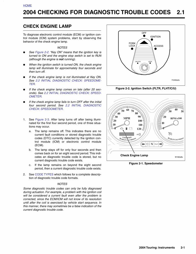
● See Figure 2-2. “Key ON” means that the ignition key isturned to ON and the engine stop switch is set to RUN(although the engine is not running).
● When the ignition switch is turned ON, the check enginelamp will illuminate for approximately four seconds andthen turn off.
● If the check engine lamp is not illuminated at Key ON.See 2.2 INITIAL DIAGNOSTIC CHECK: SPEEDOME-TER.
● If the check engine lamp comes on late (after 20 sec-onds). See 2.2 INITIAL DIAGNOSTIC CHECK: SPEED-OMETER.
● If the check engine lamp fails to turn OFF after the initialfour second period. See 2.2 INITIAL DIAGNOSTICCHECK: SPEEDOMETER.
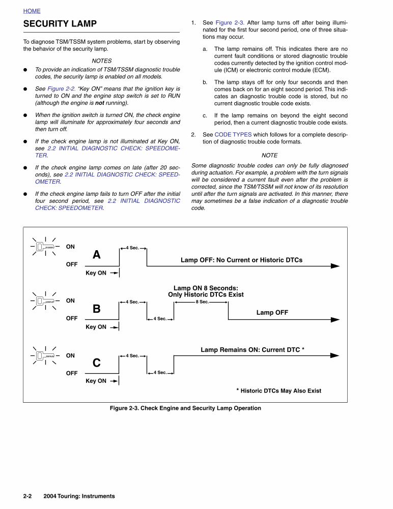
1. See Figure 2-3. After lamp turns off after being illumi-nated for the first four second period, one of three situa-tions may occur.
a. The lamp remains off. This indicates there are nocurrent fault conditions or stored diagnostic troublecodes (DTC) currently detected by the ignition con-trol module (ICM) or electronic control module(ECM).
b. The lamp stays off for only four seconds and thencomes back on for an eight second period. This indi-cates an diagnostic trouble code is stored, but nocurrent diagnostic trouble code exists.
c. If the lamp remains on beyond the eight secondperiod, then a current diagnostic trouble code exists.
2. See CODE TYPES which follows for a complete descrip-tion of diagnostic trouble code formats.
NOTES
Some diagnostic trouble codes can only be fully diagnosedduring actuation. For example, a problem with the ignition coilwill be considered a current fault even after the problem iscorrected, since the ECM/ICM will not know of its resolutionuntil after the coil is exercised by vehicle start sequence. Inthis manner, there may sometimes be a false indication of thecurrent diagnostic trouble code.
Figure 2-2. Ignition Switch (FLTR, FLHT/C/U)
Figure 2-1. Speedometer
f1240x2x
010
3020
5040
110120
60 7080
90100
0
20
3040
50
10
MPH
HARLEY-DAVIDSONCERTIFIED
RPMx100
HARLEY-DAVIDSON
f2160x8xCheck Engine Lamp
2004 Touring: Instruments 2-1
HOME
SECURITY LAMP
To diagnose TSM/TSSM system problems, start by observingthe behavior of the security lamp.
NOTES
● To provide an indication of TSM/TSSM diagnostic troublecodes, the security lamp is enabled on all models.
● See Figure 2-2. “Key ON” means that the ignition key isturned to ON and the engine stop switch is set to RUN(although the engine is not running).
● When the ignition switch is turned ON, the check enginelamp will illuminate for approximately four seconds andthen turn off.
● If the check engine lamp is not illuminated at Key ON,see 2.2 INITIAL DIAGNOSTIC CHECK: SPEEDOME-TER.
● If the check engine lamp comes on late (after 20 sec-onds), see 2.2 INITIAL DIAGNOSTIC CHECK: SPEED-OMETER.
● If the check engine lamp fails to turn OFF after the initialfour second period, see 2.2 INITIAL DIAGNOSTICCHECK: SPEEDOMETER.
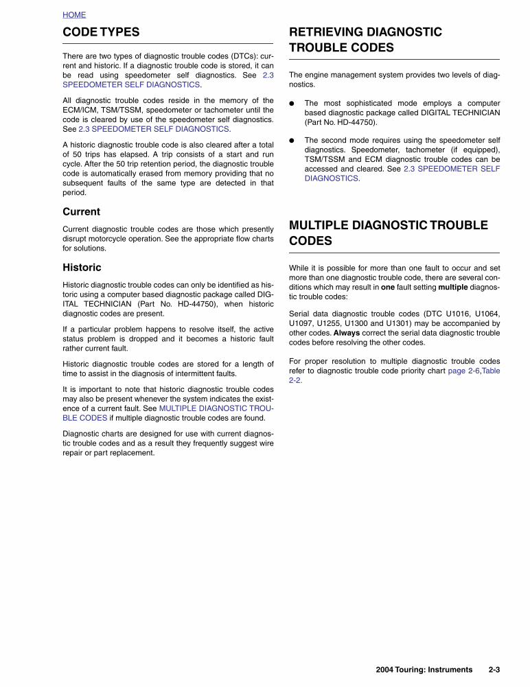
1. See Figure 2-3. After lamp turns off after being illumi-nated for the first four second period, one of three situa-tions may occur.
a. The lamp remains off. This indicates there are nocurrent fault conditions or stored diagnostic troublecodes currently detected by the ignition control mod-ule (ICM) or electronic control module (ECM).
b. The lamp stays off for only four seconds and thencomes back on for an eight second period. This indi-cates an diagnostic trouble code is stored, but nocurrent diagnostic trouble code exists.
c. If the lamp remains on beyond the eight secondperiod, then a current diagnostic trouble code exists.
2. See CODE TYPES which follows for a complete descrip-tion of diagnostic trouble code formats.
NOTE
Some diagnostic trouble codes can only be fully diagnosedduring actuation. For example, a problem with the turn signalswill be considered a current fault even after the problem iscorrected, since the TSM/TSSM will not know of its resolutionuntil after the turn signals are activated. In this manner, theremay sometimes be a false indication of a diagnostic troublecode.
Figure 2-3. Check Engine and Security Lamp Operation
ON
OFF
ON
OFF
ON
OFF
Key ON
Key ON
A
B
C
Lamp ON 8 Seconds:Only Historic DTCs Exist
Lamp OFF: No Current or Historic DTCs
Lamp Remains ON: Current DTC *
Lamp OFF
* Historic DTCs May Also Exist
4 Sec.
4 Sec.
8 Sec.
Key ON
4 Sec.
4 Sec.
4 Sec.
2-2 2004 Touring: Instruments
HOME
CODE TYPES
There are two types of diagnostic trouble codes (DTCs): cur-rent and historic. If a diagnostic trouble code is stored, it canbe read using speedometer self diagnostics. See 2.3SPEEDOMETER SELF DIAGNOSTICS.
All diagnostic trouble codes reside in the memory of theECM/ICM, TSM/TSSM, speedometer or tachometer until thecode is cleared by use of the speedometer self diagnostics.See 2.3 SPEEDOMETER SELF DIAGNOSTICS.
A historic diagnostic trouble code is also cleared after a totalof 50 trips has elapsed. A trip consists of a start and runcycle. After the 50 trip retention period, the diagnostic troublecode is automatically erased from memory providing that nosubsequent faults of the same type are detected in thatperiod.
Current
Current diagnostic trouble codes are those which presentlydisrupt motorcycle operation. See the appropriate flow chartsfor solutions.
Historic
Historic diagnostic trouble codes can only be identified as his-toric using a computer based diagnostic package called DIG-ITAL TECHNICIAN (Part No. HD-44750), when historicdiagnostic codes are present.
If a particular problem happens to resolve itself, the activestatus problem is dropped and it becomes a historic faultrather current fault.
Historic diagnostic trouble codes are stored for a length oftime to assist in the diagnosis of intermittent faults.
It is important to note that historic diagnostic trouble codesmay also be present whenever the system indicates the exist-ence of a current fault. See MULTIPLE DIAGNOSTIC TROU-BLE CODES if multiple diagnostic trouble codes are found.
Diagnostic charts are designed for use with current diagnos-tic trouble codes and as a result they frequently suggest wirerepair or part replacement.
RETRIEVING DIAGNOSTIC TROUBLE CODES
The engine management system provides two levels of diag-nostics.
● The most sophisticated mode employs a computerbased diagnostic package called DIGITAL TECHNICIAN(Part No. HD-44750).
● The second mode requires using the speedometer selfdiagnostics. Speedometer, tachometer (if equipped),TSM/TSSM and ECM diagnostic trouble codes can beaccessed and cleared. See 2.3 SPEEDOMETER SELFDIAGNOSTICS.
MULTIPLE DIAGNOSTIC TROUBLE CODES
While it is possible for more than one fault to occur and setmore than one diagnostic trouble code, there are several con-ditions which may result in one fault setting multiple diagnos-tic trouble codes:
Serial data diagnostic trouble codes (DTC U1016, U1064,U1097, U1255, U1300 and U1301) may be accompanied byother codes. Always correct the serial data diagnostic troublecodes before resolving the other codes.
For proper resolution to multiple diagnostic trouble codesrefer to diagnostic trouble code priority chart page 2-6,Table2-2.
2004 Touring: Instruments 2-3

HOME
INITIAL DIAGNOSTIC CHECK: SPEEDOMETER 2.2
GENERAL
● Constant power is supplied to the speedometer throughterminal 5 of connector [39]. The speedometer turns onwhen power is applied to terminal 1 of connector [39].The speedometer goes through an initializationsequence every time power is removed and re-applied toterminal 6. The visible part of this sequence is the checkengine lamp (in “run” mode), security lamp (models withsecurity only), backlighting, odometer and fuel level (EFIonly). Upon key ON, the check engine lamp and securitylamp will illuminate for 4 seconds and then (if parametersare normal) go out.
● To locate faulty circuits or other system problems, followthe diagnostic flow charts and tests in this section. For asystematic approach, always begin with INITIAL DIAG-NOSTICS which follows. Read the general informationand then work your way through the flow chart box bybox.
● Loss of power on any of the four power inputs willchange speedometer behavior. Refer to Table 2-1.Speedometer Function Chart-Loss Of Input.
Diagnostic Notes
If a numbered circle appears adjacent to a flow chart box,then more information is offered in the diagnostic notes. Manydiagnostic notes contain supplemental information, descrip-tions of various diagnostic tools or references to other partsof the manual where information on the location and removalof components may be obtained.
Circuit Diagram/Wire HarnessConnector Table
When working through a flow chart, refer to the illustrations,the associated circuit diagram and the wire harness connec-tor table as necessary. The wire harness connector table foreach circuit diagram identifies the connector number, descrip-tion, type and general location.
In order to perform most diagnostic routines, a Breakout Boxand a digital volt/ohm meter (DVOM) are required. See 2.5BREAKOUT BOX: SPEEDOMETER.
To perform the circuit checks with any degree of efficiency, afamiliarity with the various wire connectors is also necessary.
Figure 2-4. Remove Left Side Cover
Figure 2-5. Remove Maxi-Fuse Cover
Maxi-FuseCover
Fuse Block
f2206x8x
Maxi-Fusef2207x8x
2-4 2004 Touring: Instruments
HOME
INITIAL DIAGNOSTICS
Diagnostic Tips
● If Speedometer reads “BUS Er” with the ignition keyturned ON (engine stop switch at RUN with the engineoff), check data bus for an open or short to ground.between data link connector [91A] terminal 3 and ICMconnector [10B] terminal 12 (carbureted models), ECMconnector [78B] terminal 5 (EFI models), TSSM connec-tor [30B] terminal 3, Speedometer connector [39B] termi-nal 2 or tachometer (if equipped) connector [108B]terminal 2.
● Check for an open data test terminal between data linkconnector [91A] terminal 3 and TSM/TSSM connector[30B] terminal 3. With ignition key turned ON, serial databus voltage should be typically 0.6-0.8 volts. The rangeof acceptable voltage is greater than 0 and less than 7.0volts.
● To identify intermittents, wiggle instrument and/or vehicleharness while performing steps in the Diagnostic Checkcharts.
Diagnostic Notes
The reference numbers below correlate with the circled num-bers on the diagnostic check flow charts. See page 2-11.
1. Connect BREAKOUT BOX (Part No. HD-42682) andINSTRUMENT HARNESS ADAPTERS (Part No. HD-46601) between wire harness and speedometer.
All Speedometer diagnostic trouble codes are listed on page2-6 in Table 2-2.
Other Codes
See 3.9 INITIAL DIAGNOSTIC CHECK: TSM/TSSM for anydiagnostic trouble codes related to the turn signal module(TSM) or turn signal security module (TSSM).
See 4.4 INITIAL DIAGNOSTIC CHECK: ICM for any diagnos-tic trouble codes related to the ignition control module (ICM).
See 5.5 INITIAL DIAGNOSTIC CHECK: EFI for any diagnos-tic trouble codes related to the electronic control module(ECM).
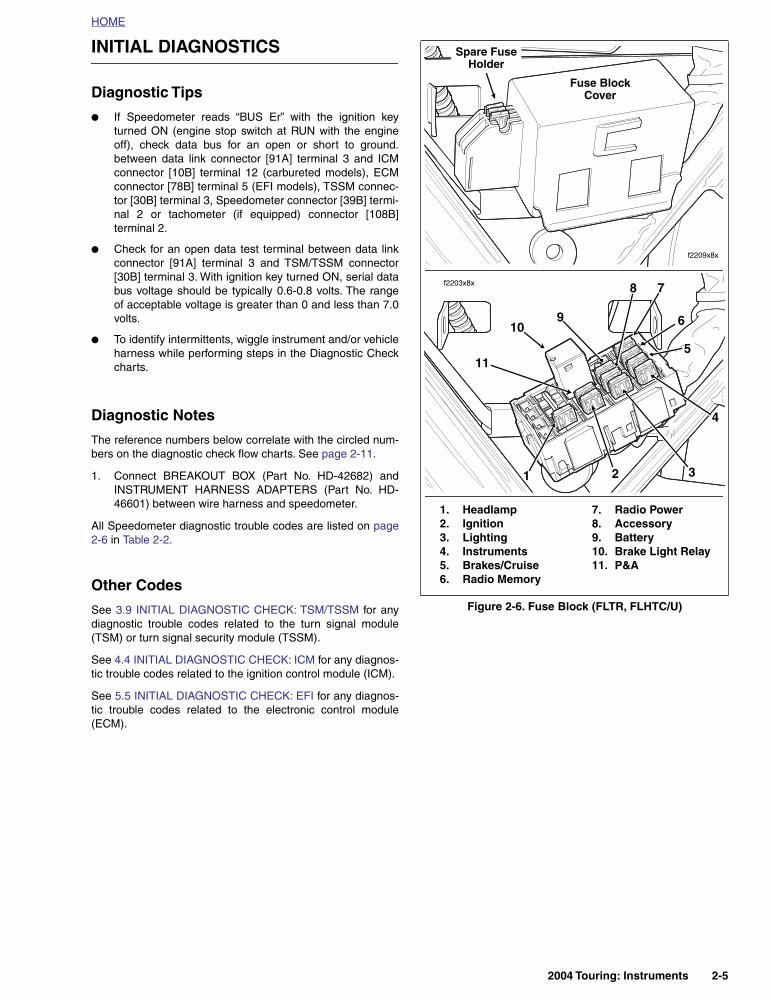
Figure 2-6. Fuse Block (FLTR, FLHTC/U)
1. Headlamp 2. Ignition3. Lighting4. Instruments5. Brakes/Cruise6. Radio Memory
7. Radio Power8. Accessory9. Battery10. Brake Light Relay11. P&A
Fuse BlockCover
Spare Fuse Holder
f2209x8x
f2203x8x
11
109
1
8 7
6
5
4
32
2004 T
ouring: Instruments 2-5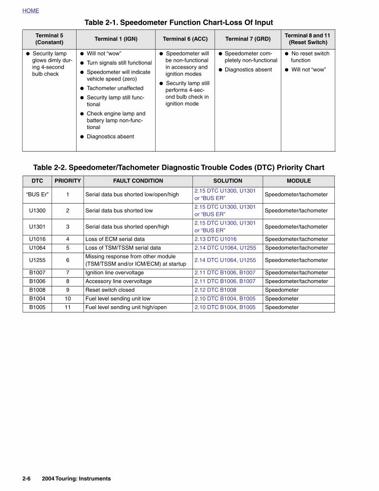
HOME
Table 2-1. Speedometer Function Chart-Loss Of Input
Terminal 5 (Constant)
Terminal 1 (IGN) Terminal 6 (ACC) Terminal 7 (GRD)Terminal 8 and 11
(Reset Switch)
● Security lamp glows dimly dur-ing 4-second bulb check
● Will not “wow”
● Turn signals still functional
● Speedometer will indicate vehicle speed (zero)
● Tachometer unaffected
● Security lamp still func-tional
● Check engine lamp and battery lamp non-func-tional
● Diagnostics absent
● Speedometer will be non-functional in accessory and ignition modes
● Security lamp still performs 4-sec-ond bulb check in ignition mode
● Speedometer com-pletely non-functional
● Diagnostics absent
● No reset switch function
● Will not “wow”
Table 2-2. Speedometer/Tachometer Diagnostic Trouble Codes (DTC) Priority Chart
DTC PRIORITY FAULT CONDITION SOLUTION MODULE
“BUS Er” 1 Serial data bus shorted low/open/high 2.15 DTC U1300, U1301 or “BUS ER”
Speedometer/tachometer
U1300 2 Serial data bus shorted low2.15 DTC U1300, U1301 or “BUS ER”
Speedometer/tachometer
U1301 3 Serial data bus shorted open/high2.15 DTC U1300, U1301 or “BUS ER”
Speedometer/tachometer
U1016 4 Loss of ECM serial data 2.13 DTC U1016 Speedometer/tachometer
U1064 5 Loss of TSM/TSSM serial data 2.14 DTC U1064, U1255 Speedometer/tachometer
U1255 6Missing response from other module (TSM/TSSM and/or ICM/ECM) at startup
2.14 DTC U1064, U1255 Speedometer/tachometer
B1007 7 Ignition line overvoltage 2.11 DTC B1006, B1007 Speedometer/tachometer
B1006 8 Accessory line overvoltage 2.11 DTC B1006, B1007 Speedometer/tachometer
B1008 9 Reset switch closed 2.12 DTC B1008 Speedometer
B1004 10 Fuel level sending unit low 2.10 DTC B1004, B1005 Speedometer
B1005 11 Fuel level sending unit high/open 2.10 DTC B1004, B1005 Speedometer
2-6 2004 Touring: Instruments
HOME
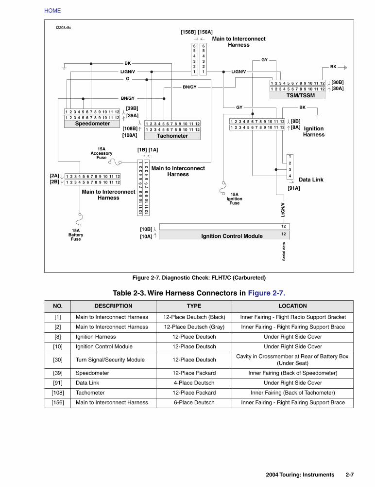
Figure 2-7. Diagnostic Check: FLHT/C (Carbureted)
Table 2-3. Wire Harness Connectors in Figure 2-7.
NO. DESCRIPTION TYPE LOCATION
[1] Main to Interconnect Harness 12-Place Deutsch (Black) Inner Fairing - Right Radio Support Bracket
[2] Main to Interconnect Harness 12-Place Deutsch (Gray) Inner Fairing - Right Fairing Support Brace
[8] Ignition Harness 12-Place Deutsch Under Right Side Cover
[10] Ignition Control Module 12-Place Deutsch Under Right Side Cover
[30] Turn Signal/Security Module 12-Place DeutschCavity in Crossmember at Rear of Battery Box
(Under Seat)
[39] Speedometer 12-Place Packard Inner Fairing (Back of Speedometer)
[91] Data Link 4-Place Deutsch Under Right Side Cover
[108] Tachometer 12-Place Packard Inner Fairing (Back of Tachometer)
[156] Main to Interconnect Harness 6-Place Deutsch Inner Fairing - Right Fairing Support Brace
12
12
3
1
2
4
321 654 987 121110321 654 987 121110
321 654 987 121110321 654 987 121110
321 654 987 121110321 654 987 121110
1011
127
89
45
61
23
1011
127
89
45
61
23
321 654 987 121110321 654 987 121110
2
43
1
56
2
43
1
56
321 654 987 121110321 654 987 121110
Ignition Control Module
Data Link
TSM/TSSM
LtG
N/V
15AIgnition
Fuse
GY
[8B][8A]
[91A]
LtGN/V
BK
LtGN/V
[39B][39A]
[10B][10A]
Speedometer
O
BK
Ser
ial d
ata
[108B][108A] Tachometer
BN/GY
[156B] [156A]
[30B][30A]
15AAccessory
Fuse
[1B] [1A]
Main to InterconnectHarness
Ignition Harness
Main to InterconnectHarness
f2208z8x
15ABattery
Fuse
[2A][2B]
Main to InterconnectHarness
BK
GY
BN/GY
2004 Touring: Instruments 2-7

HOME
Figure 2-8. Diagnostic Check: FLHR/S (Carbureted)
Table 2-4. Wire Harness Connectors in Figure 2-8.
NO. DESCRIPTION TYPE LOCATION
[8] Ignition Harness 12-Place Deutsch Under Right Side Cover
[10] Ignition Control Module 12-Place Deutsch Under Right Side Cover
[30] Turn Signal/Security Module 12-Place DeutschCavity in Crossmember at Rear of
Battery Box (Under Seat)
[39] Speedometer 12-Place Packard Under Console (Back of Speedometer)
[91] Data Link 4-Place Deutsch Under Right Side Cover
321 654 987 121110321 654 987 121110
321 654 987 121110321 654 987 121110
321 654 987 121110321 654 987 121110
3
1
2
4
12
12
Data Link
TSM/TSSM
LtG
N/V
GY
[30B][30A]
[91A]
LtGN/V
BK[39B][39A]
[10B][10A]
Speedometer
O
BK
Ser
ial d
ata
Ignition Control Module
BN/GY
15AIgnition
Fuse
15AAccessory
Fuse
LtGN/V
[8B][8A]
Ignition Harness
15ABattery
Fuse
f2208y8x
BK
BN/GY
GY
2-8 2004 Touring: Instruments
HOME
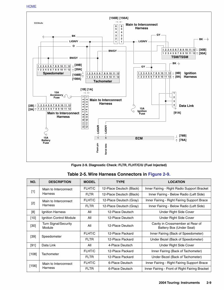
Figure 2-9. Diagnostic Check: FLTR, FLHT/C/U (Fuel Injected)
Table 2-5. Wire Harness Connectors in Figure 2-9.
NO. DESCRIPTION MODEL TYPE LOCATION
[1]Main to Interconnect Harness
FLHT/C 12-Place Deutsch (Black) Inner Fairing - Right Radio Support Bracket
FLTR 12-Place Deutsch (Black) Inner Fairing - Below Radio (Left Side)
[2]Main to Interconnect Harness
FLHT/C 12-Place Deutsch (Gray) Inner Fairing - Right Fairing Support Brace
FLTR 12-Place Deutsch (Gray) Inner Fairing - Below Radio (Left Side)
[8] Ignition Harness All 12-Place Deutsch Under Right Side Cover
[10] Ignition Control Module All 12-Place Deutsch Under Right Side Cover
[30]Turn Signal/Security Module
All 12-Place DeutschCavity in Crossmember at Rear of
Battery Box (Under Seat)
[39] SpeedometerFLHT/C 12-Place Packard Inner Fairing (Back of Speedometer)
FLTR 12-Place Packard Under Bezel (Back of Speedometer)
[91] Data Link All 4-Place Deutsch Under Right Side Cover
[108] TachometerFLHT/C 12-Place Packard Inner Fairing (Back of Tachometer)
FLTR 12-Place Packard Under Bezel (Back of Tachometer)
[156]Main to Interconnect Harness
FLHT/C 6-Place Deutsch Inner Fairing - Right Fairing Support Brace
FLTR 6-Place Deutsch Inner Fairing - Front of Right Fairing Bracket
51
3
1
2
4
321 654 987 121110321 654 987 121110
321 654 987 121110321 654 987 121110
321 654 987 121110321 654 987 121110
1011
127
89
45
61
23
1011
127
89
45
61
23
321 654 987 121110321 654 987 121110
321 654 987 121110321 654 987 121110
2
43
1
56
2
43
1
56
ECM
Data Link
TSM/TSSM
LtG
N/V
15AIgnition
Fuse
GY
[8B][8A]
[91A]
LtGN/V
BK
LtGN/V
[39B][39A]
[78B][78A]
Speedometer
O
BK
Ser
ial d
ata
[108B][108A]
Tachometer
BN/GY
[156B] [156A]
[30B][30A]
15AAccessory
Fuse
[1B] [1A]
Main to InterconnectHarness
Ignition Harness
Main to InterconnectHarness
f2208u8x
15ABattery
Fuse
[2B][2A]
Main to InterconnectHarness
LtG
N/R
BK
BN/GY
GY
Fla
sh p
in
2004 Touring: Instruments 2-9
HOME
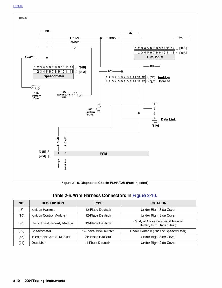
Figure 2-10. Diagnostic Check: FLHR/C/S (Fuel Injected)
Table 2-6. Wire Harness Connectors in Figure 2-10.
NO. DESCRIPTION TYPE LOCATION
[8] Ignition Harness 12-Place Deutsch Under Right Side Cover
[10] Ignition Control Module 12-Place Deutsch Under Right Side Cover
[30] Turn Signal/Security Module 12-Place DeutschCavity in Crossmember at Rear of
Battery Box (Under Seat)
[39] Speedometer 12-Place Mini-Deutsch Under Console (Back of Speedometer)
[78] Electronic Control Module 36-Place Packard Under Right Side Cover
[91] Data Link 4-Place Deutsch Under Right Side Cover
51
321 654 987 121110321 654 987 121110
321 654 987 121110321 654 987 121110
321 654 987 121110321 654 987 121110
3
1
2
4
f2208t8x
Data Link
TSM/TSSM
LtG
N/V
GY
[30B][30A]
[91A]
LtGN/V
BK[39B][39A]
[78B][78A]
Speedometer
O
BK
Ser
ial d
ata
ECM
BN/GY
15AIgnition
Fuse
15AAccessory
Fuse
LtGN/V
[8B][8A]
Ignition Harness
15ABattery
Fuse
LtG
N/R
BK
BN/GY
GY
Fla
sh p
in
2-10 2004 Touring: Instruments

HOME
Diagnostic Check (Part 1 of 2)
YES.Starts and
runs.
For carbureted models, see 4.10 STARTS, THEN STALLS.
For EFI models, see 5.12 STARTS, THEN STALLS.
See 1.2 STARTING SYSTEM DIAGNOSIS.
YES.Starts, then
stalls.
NO.Cranks, but will not start.
NO. Engine will not
crank.
For carbureted models, see 4.9 ENGINE CRANKS, BUT WILL NOT START. For EFI models, see 5.10 ENGINE CRANKS,
BUT WILL NOT START.
NO
Check for continuity to ground on terminal 7 of speedometer. Wiggle harness during con-
tinuity check. Continuity present?
YES
YES NO
YES NO
Check for battery voltage at terminal 5 of speedometer
while wiggling harness. Bat-tery voltage continuously
present?
Replace speedometer. Replace speedometer reset switch.
1
Check for diagnostic trouble codes. See 2.3 SPEEDOMETER SELF
DIAGNOSTICSCodes found?
Refer to applicable diagnostic trouble code priority chart. All diagnostic codes
are listed on page 2-6 in Table 2-2. Codes are listed by priority.
STOP
Go to Diagnostic Check (Part 2 of 2).
Locate and repair open between terminal 5 and
battery fuse.
Locate and repair open between terminal 7
and ground.
NO
Unable to enter diagnostic mode. With ignition switch OFF, press and
release odometer reset switch. Does odometer display appear with
display backlighting?
NO
No codes displayed. For symptoms that may not set diagnostic trouble codes,
refer to Table 2-1.
NOYES
YES
With connector [39] disconnected from speedometer, check continuity (with ignition switch OFF) between terminals 8 and 11 on
Breakout Box. Continuity present when speedometer reset switch is depressed and
infinity when released?
Does enginestart?
2004 Touring: Instruments 2-11

HOME
Diagnostic Check (Part 2 of 2)
YES
Remove and inspect vehi-cle speed sensor. Debris
present?
Remove debris. Reinstall vehicle speed sensor.
NO
YES
Continued from Diagnostic Check (Part 1 of 2).Perform “wow” test. See 2.3 SPEEDOMETER SELF DIAGNOSTICS.
The following features should be functional1) backlight should illuminate2) needle should sweep its full range of motion3) LED’s that should illuminate:
• check engine• battery• security (all models)
4) LED’s that may illuminate: • low fuel (EFI models)• cruise (although not cruise equipped on some models)
Are all features functional?
Turn key to ACC. Is backlight present?
YES NO
Is instrument fuse blown?
Replace Speedometer.
YES NO
Locate and repair source of fault. Replace fuse.
Locate and repair open between terminal 1 of
connector [39] and instrument fuse.
Is problem intermittent?
YES
NO
Check for battery voltage at breakout box terminal 6. Battery voltage present?
Replace speedometer.
YES
1
NO
Tachometer Inoperative (no engine speed).
See Test 2.4 (Part 1 of 2).
YES
YESIntermittent vehicle speed
indication.
NO
With ignition switch turned to IGN, check for battery voltage at terminal 1 of Breakout Box.
Battery voltage present?
Is accessory fuse blown?
YES
Locate and repair source of fault. Replace fuse.
NO
Locate and repair open on O/W wire between termin al 6 of con-nector [39] and accessory fuse.
Repeat Diagnostic Check while wiggling harnesses.
Intermittent present?
Locate and repair intermittent.
YES NO
No trouble found.
NO
Check for damaged wiring/loose connection between
vehicle speed sensor and ICM/ECM. Is wiring damage/loose
connection present?
YES NO
Replace Speedometer.Locate and repair source of fault.
2-12 2004 Touring: Instruments
HOME
SPEEDOMETER SELF DIAGNOSTICS 2.3
GENERAL
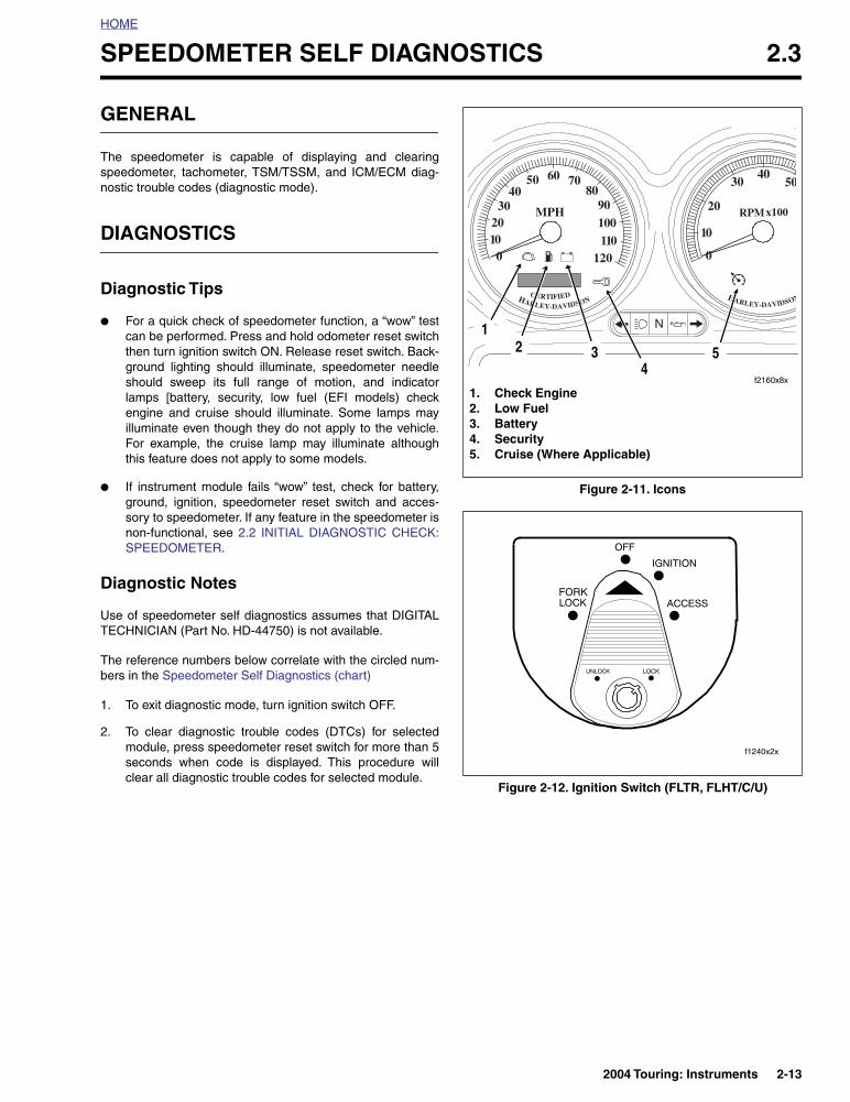
The speedometer is capable of displaying and clearingspeedometer, tachometer, TSM/TSSM, and ICM/ECM diag-nostic trouble codes (diagnostic mode).
DIAGNOSTICS
Diagnostic Tips
● For a quick check of speedometer function, a “wow” testcan be performed. Press and hold odometer reset switchthen turn ignition switch ON. Release reset switch. Back-ground lighting should illuminate, speedometer needleshould sweep its full range of motion, and indicatorlamps [battery, security, low fuel (EFI models) checkengine and cruise should illuminate. Some lamps mayilluminate even though they do not apply to the vehicle.For example, the cruise lamp may illuminate althoughthis feature does not apply to some models.
● If instrument module fails “wow” test, check for battery,ground, ignition, speedometer reset switch and acces-sory to speedometer. If any feature in the speedometer isnon-functional, see 2.2 INITIAL DIAGNOSTIC CHECK:SPEEDOMETER.
Diagnostic Notes
Use of speedometer self diagnostics assumes that DIGITALTECHNICIAN (Part No. HD-44750) is not available.
The reference numbers below correlate with the circled num-bers in the Speedometer Self Diagnostics (chart)
1. To exit diagnostic mode, turn ignition switch OFF.
2. To clear diagnostic trouble codes (DTCs) for selectedmodule, press speedometer reset switch for more than 5seconds when code is displayed. This procedure willclear all diagnostic trouble codes for selected module.
Figure 2-11. Icons
Figure 2-12. Ignition Switch (FLTR, FLHT/C/U)
010
3020
5040
110120
60 7080
90100
0
20
3040
50
10
MPH
HARLEY-DAVIDSONCERTIFIED
RPMx100
HARLEY-DAVIDSON
f2160x8x
1. Check Engine2. Low Fuel3. Battery4. Security5. Cruise (Where Applicable)
12 3
45
f1240x2x
2004 Touring: Instruments 2-13

HOME
Speedometer Self Diagnostics (chart)
Figure 2-13. Speedometer Self Diagnostics
”P” flashing.
”S” flashing.
”SP” flashing.
To choose TSM/TSSM, press and
release reset switch.
YESTo choose ICM, press and
release reset switch.
“none” displayed.
To display DTCs for speedometer, press and
hold reset switch for more than 5 seconds.
To display DTCs for the ECM/ICM, press and hold reset switch for
more than 5 seconds.
To display DTCs for TSM/TSSM, press and
hold reset switch for more than 5 seconds.
To choose Speedometer, press and release reset
switch.
NO
YES
2
”T” flashing.
To choose Tachometer, press and release reset
switch.
To display DTCs for tachometer, press and
hold reset switch for more than 5 seconds.
Press and release reset switch. Part num-ber of module will be
displayed.
Press and release reset switch again to continue to
next module.
Device response?
“no rsp” displayed.* Tachometer malfunction. See 2.4 SPEEDOMETER/
TACHOMETER.
* Models not equippedwith a tachometer willdisplay “no rsp” nor-mally.
DTC displayed.
NO
Press and release reset switch.
Are more DTCs displayed?
1
While holding odometer reset switch in, turn ignition switch to IGN. Make sure Run/Stop switch is in RUN position.
Release reset switch. Does “diag” appear?
YES NO
“end” displayed.To clear all DTCs for
selected module hold reset switch for more than 5 sec-onds. If DTCs are not to be cleared, Press and release reset switch. Part number of
module will be displayed.
See 2.2 INITIAL DIAGNOSTIC CHECK: SPEEDOMETER.
Press and release reset switch.
“PSSPT” appears.
2-14 2004 Touring: Instruments
HOME
SPEEDOMETER/TACHOMETER 2.4
GENERAL
NOTE
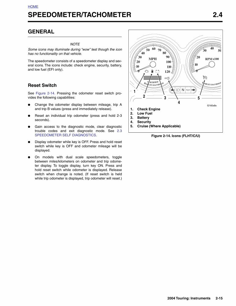
Some icons may illuminate during “wow” test though the iconhas no functionality on that vehicle.
The speedometer consists of a speedometer display and sev-eral icons. The icons include: check engine, security, battery,and low fuel (EFI only).
Reset Switch
See Figure 2-14. Pressing the odometer reset switch pro-vides the following capabilities:
● Change the odometer display between mileage, trip Aand trip B values (press and immediately release).
● Reset an individual trip odometer (press and hold 2-3seconds).
● Gain access to the diagnostic mode, clear diagnostictrouble codes and exit diagnostic mode. See 2.3SPEEDOMETER SELF DIAGNOSTICS.
● Display odometer while key is OFF. Press and hold resetswitch while key is OFF and odometer mileage will bedisplayed.
● On models with dual scale speedometers, togglebetween miles/kilometers on odometer and trip odome-ter display. To toggle display, turn key ON. Press andhold reset switch while odometer is displayed. Releaseswitch when change is noted. (If reset switch is heldwhile trip odometer is displayed, trip odometer will reset.)
Figure 2-14. Icons (FLHT/C/U)
010
3020
5040
110120
60 7080
90100
0
20
3040
50
10
MPH
HARLEY-DAVIDSONCERTIFIED
RPMx100
HARLEY-DAVIDSON
f2160x8x
1. Check Engine2. Low Fuel3. Battery4. Security5. Cruise (Where Applicable)
12 3
45
2004 Touring: Instruments 2-15
HOME
SPEEDOMETER THEORYOF OPERATION
The speedometer consists of a vehicle speed sensor, ICM/ECM, odometer reset switch and the speedometer. The vehi-cle speed sensor is mounted on the right side of transmissioncase below the starter. The sensor circuitry is that of a Hall-Effect sensor that is triggered by the gear teeth of 4th gear onthe transmission mainshaft.
The output from the sensor is a series of pulses that are inter-preted by ICM/ECM circuitry, converted into serial data insidethe ICM/ECM then sent to the speedometer to control theposition of the speedometer needle and the liquid crystal(LCD) odometer display. The vehicle speed serial data is alsotransmitted to the TSM/TSSM for turn signal cancellation.
The odometer mileage is permanently stored and will not belost when electrical power is turned off or disconnected. Theodometer reset switch allows switching between the odome-ter, trip odometer A and trip odometer B displays.
To zero the trip odometer, have the desired trip odometer dis-play visible, press and keep the reset switch depressed. Thetrip odometer mileage will be displayed for 2-3 seconds andthen the trip mileage will return to zero miles.
The odometer can display six numbers to indicate a maxi-mum of 999999 miles/kilometers. The trip odometers can dis-play six numbers with a tenth of a mile accuracy for amaximum of 99999.9 miles/kilometers.
Job/Time Code Values
Dealership technicians filing warranty claims should use thejob/time code values in Digital Technician.
TACHOMETER THEORYOF OPERATION
The tachometer receives serial data from the ICM/ECM. Thetachometer interprets the serial data and converts it intotachometer needle movement.
DIAGNOSTICS
Diagnostic Notes
The reference numbers below correlate with circled numberson the tachometer diagnostic flow chart.
1. If problems are intermittent, wiggle harness while per-forming tests.
2. Connect BREAKOUT BOX (Part No. HD-42682) andINSTRUMENT HARNESS ADAPTERS (Part No. HD-46601) between wire harness and tachometer.
3. Use HARNESS CONNECTOR TEST KIT (Part No. HD-41404), black pin probe and patch cord.
2-16 2004 Touring: Instruments

HOME
Test 2.4 (Part 1 of 2)TACHOMETER INOPERATIVE
Perform “wow” test. See 2.3 SPEEDOMETER SELF DIAGNOSTICS.
The following features should be functional1) backlight should illuminate2) needle should sweep its full range of motion3) LED’s may illuminate:
cruise (although not cruise equipped on some models)pursuit (although may not be a police vehicle)
Are all features functional?
YES NO
Locate and repair source of fault. Replace fuse.
Locate and repair open in orange wire
between terminal 1 of connector [108] and
instrument fuse.
STOP
Go to Test 2.4 (Part 2 of 2).
YES
Check for battery voltage at terminal 1 of breakout box. Is battery voltage
present?
NO
NO
Is instrument fuse blown?
YES
Repeat Diagnostic Check while wiggling
harnesses.
NO
No trouble found.
Is problem intermittent?
YES
NO
Locate and repair open on LGN/V wire.
Check for continuity between breakout box terminal 2 and terminal 7 of connector [20].
Is continuity present?
YES
2004 Touring: Instruments 2-17
HOME
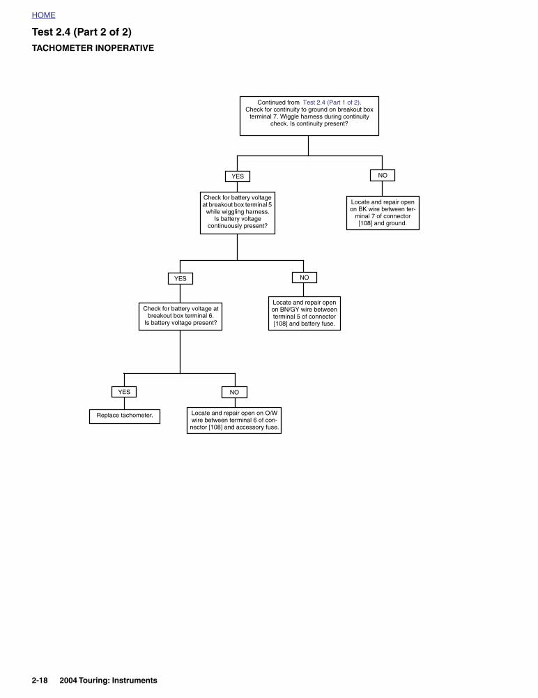
Test 2.4 (Part 2 of 2)TACHOMETER INOPERATIVE
Check for battery voltage at breakout box terminal 6.
Is battery voltage present?
Check for battery voltage at breakout box terminal 5
while wiggling harness. Is battery voltage
continuously present?
Replace tachometer. Locate and repair open on O/W wire between terminal 6 of con-
nector [108] and accessory fuse.
Continued from Test 2.4 (Part 1 of 2).Check for continuity to ground on breakout box
terminal 7. Wiggle harness during continuity check. Is continuity present?
YES NO
YES NO
Locate and repair open on BK wire between ter-
minal 7 of connector [108] and ground.
NO
Locate and repair open on BN/GY wire between terminal 5 of connector [108] and battery fuse.
YES
2-18 2004 Touring: Instruments
HOME
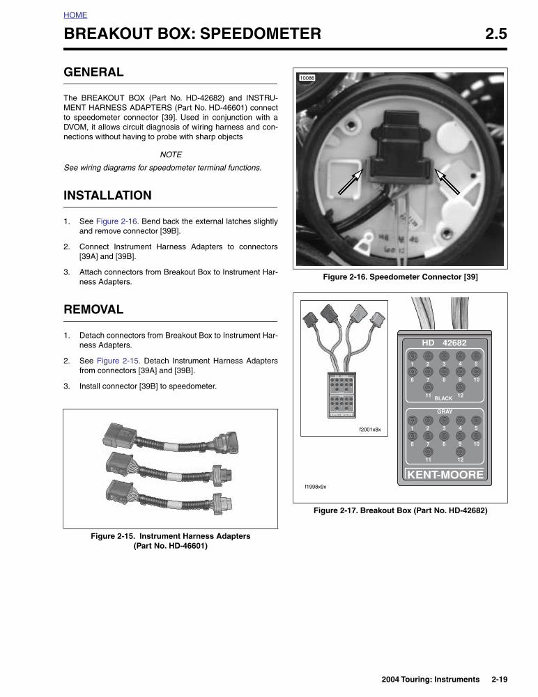
BREAKOUT BOX: SPEEDOMETER 2.5
GENERAL
The BREAKOUT BOX (Part No. HD-42682) and INSTRU-MENT HARNESS ADAPTERS (Part No. HD-46601) connectto speedometer connector [39]. Used in conjunction with aDVOM, it allows circuit diagnosis of wiring harness and con-nections without having to probe with sharp objects
NOTE
See wiring diagrams for speedometer terminal functions.
INSTALLATION
1. See Figure 2-16. Bend back the external latches slightlyand remove connector [39B].
2. Connect Instrument Harness Adapters to connectors[39A] and [39B].
3. Attach connectors from Breakout Box to Instrument Har-ness Adapters.
REMOVAL
1. Detach connectors from Breakout Box to Instrument Har-ness Adapters.
2. See Figure 2-15. Detach Instrument Harness Adaptersfrom connectors [39A] and [39B].
3. Install connector [39B] to speedometer.
Figure 2-15. Instrument Harness Adapters (Part No. HD-46601)
Figure 2-16. Speedometer Connector [39]
Figure 2-17. Breakout Box (Part No. HD-42682)
10086
f2001x8x
f1998x9x
2004 Touring: Instruments 2-19
HOME
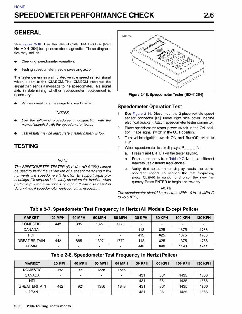
SPEEDOMETER PERFORMANCE CHECK 2.6
GENERAL
See Figure 2-18. Use the SPEEDOMETER TESTER (PartNo. HD-41354) for speedometer diagnostics. These diagnos-tics may include:
● Checking speedometer operation.
● Testing speedometer needle sweeping action.
The tester generates a simulated vehicle speed sensor signalwhich is sent to the ICM/ECM. The ICM/ECM interprets thesignal then sends a message to the speedometer. This signalaids in determining whether speedometer replacement isnecessary.
● Verifies serial data message to speedometer.
NOTES
● Use the following procedures in conjunction with themanual supplied with the speedometer tester.
● Test results may be inaccurate if tester battery is low.
TESTING
NOTE
The SPEEDOMETER TESTER (Part No. HD-41354) cannotbe used to verify the calibration of a speedometer and it willnot verify the speedometer’s function to support legal pro-ceedings. It’s purpose is to verify speedometer function whenperforming service diagnosis or repair. It can also assist indetermining if speedometer replacement is necessary.
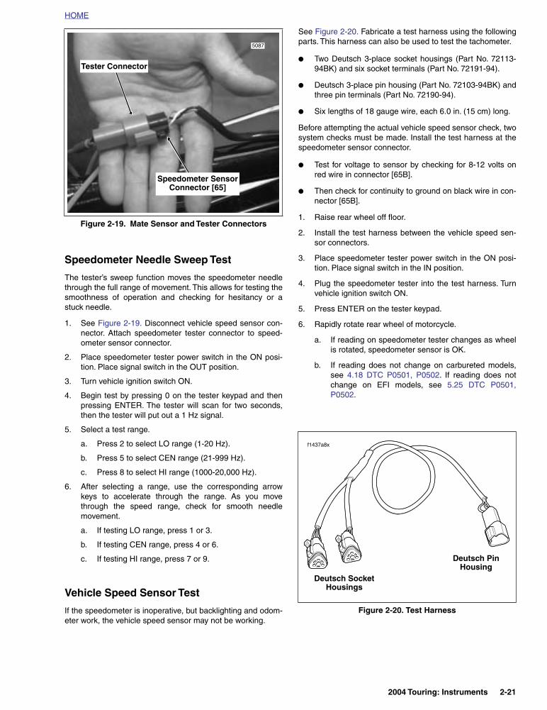
Speedometer Operation Test1. See Figure 2-19. Disconnect the 3-place vehicle speed
sensor connector [65] under right side cover (behindelectrical bracket). Attach speedometer tester connector.
2. Place speedometer tester power switch in the ON posi-tion. Place signal switch in the OUT position.
3. Turn vehicle ignition switch ON and Run/Off switch toRun.
4. When speedometer tester displays “P_ _ _ _1”:
a. Press 1 and ENTER on the tester keypad.
b. Enter a frequency from Table 2-7. Note that differentmarkets use different frequencies.
c. Verify that speedometer display reads the corre-sponding speed. To change the test frequency,press CLEAR to cancel and enter the new fre-quency. Press ENTER to begin and reverify.
NOTEThe speedometer should be accurate within -0 to +4 MPH (0to +6.5 KPH).
Figure 2-18. Speedometer Tester (HD-41354)
hd41354
Table 2-7. Speedometer Test Frequency in Hertz (All Models Except Police)
MARKET 20 MPH 40 MPH 60 MPH 80 MPH 30 KPH 60 KPH 100 KPH 130 KPH
DOMESTIC 442 885 1327 1770 - - - -
CANADA - - - - 413 825 1375 1788
HDI - - - - 413 825 1375 1788
GREAT BRITAIN 442 885 1327 1770 413 825 1375 1788
JAPAN - - - - 448 896 1493 1941
Table 2-8. Speedometer Test Frequency in Hertz (Police)
MARKET 20 MPH 40 MPH 60 MPH 80 MPH 30 KPH 60 KPH 100 KPH 130 KPH
DOMESTIC 462 924 1386 1848 - - - -
CANADA - - - - 431 861 1435 1866
HDI - - - - 431 861 1435 1866
GREAT BRITAIN 462 924 1386 1848 431 861 1435 1866
JAPAN - - - - 431 861 1435 1866
2-20 2004 Touring: Instruments
HOME
Speedometer Needle Sweep Test
The tester’s sweep function moves the speedometer needlethrough the full range of movement. This allows for testing thesmoothness of operation and checking for hesitancy or astuck needle.
1. See Figure 2-19. Disconnect vehicle speed sensor con-nector. Attach speedometer tester connector to speed-ometer sensor connector.
2. Place speedometer tester power switch in the ON posi-tion. Place signal switch in the OUT position.
3. Turn vehicle ignition switch ON.
4. Begin test by pressing 0 on the tester keypad and thenpressing ENTER. The tester will scan for two seconds,then the tester will put out a 1 Hz signal.
5. Select a test range.
a. Press 2 to select LO range (1-20 Hz).
b. Press 5 to select CEN range (21-999 Hz).
c. Press 8 to select HI range (1000-20,000 Hz).
6. After selecting a range, use the corresponding arrowkeys to accelerate through the range. As you movethrough the speed range, check for smooth needlemovement.
a. If testing LO range, press 1 or 3.
b. If testing CEN range, press 4 or 6.
c. If testing HI range, press 7 or 9.
Vehicle Speed Sensor Test
If the speedometer is inoperative, but backlighting and odom-eter work, the vehicle speed sensor may not be working.
See Figure 2-20. Fabricate a test harness using the followingparts. This harness can also be used to test the tachometer.
● Two Deutsch 3-place socket housings (Part No. 72113-94BK) and six socket terminals (Part No. 72191-94).
● Deutsch 3-place pin housing (Part No. 72103-94BK) andthree pin terminals (Part No. 72190-94).
● Six lengths of 18 gauge wire, each 6.0 in. (15 cm) long.
Before attempting the actual vehicle speed sensor check, twosystem checks must be made. Install the test harness at thespeedometer sensor connector.
● Test for voltage to sensor by checking for 8-12 volts onred wire in connector [65B].
● Then check for continuity to ground on black wire in con-nector [65B].
1. Raise rear wheel off floor.
2. Install the test harness between the vehicle speed sen-sor connectors.
3. Place speedometer tester power switch in the ON posi-tion. Place signal switch in the IN position.
4. Plug the speedometer tester into the test harness. Turnvehicle ignition switch ON.
5. Press ENTER on the tester keypad.
6. Rapidly rotate rear wheel of motorcycle.
a. If reading on speedometer tester changes as wheelis rotated, speedometer sensor is OK.
b. If reading does not change on carbureted models,see 4.18 DTC P0501, P0502. If reading does notchange on EFI models, see 5.25 DTC P0501,P0502.
Figure 2-19. Mate Sensor and Tester Connectors
5087
Speedometer SensorConnector [65]
Tester Connector
Figure 2-20. Test Harness
Deutsch Socket Housings
Deutsch PinHousing
f1437a8x
2004 Touring: Instruments 2-21
HOME
FUEL GAUGE OPERATION 2.7
THEORY OF OPERATION
With ignition switch ON, the fuel gauge is connected to +12volts. Current flows through the gauge and variable resistor inthe fuel gauge sending unit to ground. The sending unit floatcontrols the amount of resistance in the variable resistor.
Inoperative gauges may be caused by three circumstances.
● Sender or fuel gauge not grounded.
● Malfunction in sender or fuel gauge.
● Broken or disconnected wire from ignition switch to fuelgauge.
Use the FUEL GAUGE AND SENDER TEST to test suspectcomponents.
FUEL GAUGE AND SENDER TEST
NOTE
Always refer to the applicable wiring diagram (at the rear ofthis manual) when troubleshooting instruments or gauges.
1. Remove gauge. Ground Y/W wire of fuel gauge senderlocated at bottom of gauge. Turn ignition switch ON.
a. Fuel gauge must indicate FULL. If gauge indicatedFULL, gauge is functioning correctly. Proceed tostep 2.
b. If gauge did not indicate FULL, proceed to step 3.
2. Set MULTI-METER (Part No. HD-35500) to RXI scale tomeasure the resistance of the sending unit. Place oneprobe on Y/W and the other probe on a good ground.
FLHT/C/U, FLTR:
If fuel tank is full, the reading should be 7-14 ohms. Anempty tank should have a 74-95 ohm resistance. A halffull tank will be approximately 30-38 ohms.
FLHR/C/S:
If fuel tank is full, the reading should be 27-40 ohms. Anempty tank should have a 240-264 ohm resistance. Ahalf full tank will be approximately 97-118 ohms.
ALL MODELS:
If a very high resistance or infinity is indicated on themeter, the sender may be “open” or not grounded. Checkthat sender and fuel tank are grounded by placing oneprobe of Multi-Meter on sender flange and the otherprobe on crankcase. Meter must indicate one ohm orless. Replace sender if one ohm or less was present. If ahigher resistance is present, check for poor connectionon ground wire.
3. Check voltage to O/W (+) and BK (-) wire of fuel gaugeconnector [117] if gauge did not indicate FULL.
a. Correct reading is equivalent to battery voltage.
b. If battery voltage is not present check for broken ordisconnected wire. Replace gauge if wiring problemis not found.
2-22 2004 Touring: Instruments

HOME
INDICATOR LAMPS: FLTR, FLHT/C/U 2.8
GENERAL
See Figure 2-21. All models except FLHR/C/S are equippedwith incandescent indicator lamps which may be replacedindividually. See the Touring Models Service Manual for lampreplacement procedure. See DIAGNOSTICS which followsfor troubleshooting procedures.
Job/Time Code Values
Dealership technicians filing warranty claims should use thejob/time code values printed in bold text underneath theappropriate repair.
Diagnostic Notes
The reference number below correlates with the circled num-ber on the Diagnostics flow charts on the next page.
1. Connect BREAKOUT BOX (Part No. HD-42682) (black)between wire harness connector [20A] and instrumentsconnector [20B].
Table 2-9. Indicator Lamp Connector [20]
TERMINAL WIRE
COLORFUNCTION
3 Brown Right Turn
4 White High Beam
5 Violet Left Turn
6 Orange Neutral/Oil Pressure Power
8 Tan Neutral Lamp To Switch
9 Green/Yellow Oil Pressure Lamp To Switch
12 BlackTurn Signal/High Beam
Ground
Table 2-10. Indicator Lamp Wiring
INDICATOR LAMP CONNECTION
Oil pressure Ground Through Switch
Neutral Ground Through Switch
High beam 12 VDC When Active
Right/left turn 12 VDC When Active
Figure 2-21. Indicator Lamp Assembly(FLTR, FLHT/C/U)
N
f1346x2x
RubberBoot
BulbHousing
PaddleLense
Indicator LampConnector [21]
2004 Touring: Instruments 2-23

HOME
DIAGNOSTICS
Oil Pressure or Neutral Indicator Will Not Function
High Beam or R/L Turn Signal Indicator Will Not Function
Turn on ignition switch. Check for 12 VDC at Breakout Box terminal 6.
Turn off ignition switch.Was 12 VDC present?
Check for continuity to ground at Breakout Box terminal 8 (neutral) and terminal 9 (oil pressure).
Is continuity present?
YES
5048
Replace indicator lamp.
YES
Check for blown fuses or locate open.
NO
Check each terminal for continuity to ground through switch.
Is continuity present?
NO
Repair open in GN/Y wire (oil pressure) or
TN wire (neutral).
YES
Replace oilpressure switch.
NO
Replace neutral switch.
NO
5048
5161 5157
5191
1
Check for ground at Breakout Box terminal 12.
Is ground present?
Check for 12 VDC when circuit is active: Breakout Box terminal 5 (left turn), terminal 3
(right turn) or terminal 4 (high beam). Is voltage present?
YES
5048
Replace indicator lamp.
YES
Locate and repair open in circuit.
NO
Locate and repairopen in circuit.
NO
5191
5048
1
2-24 2004 Touring: Instruments
HOME
INDICATOR LAMPS: FLHR/C/S 2.9
GENERAL
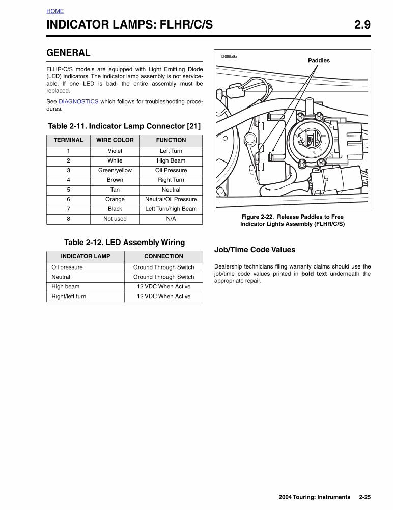
FLHR/C/S models are equipped with Light Emitting Diode(LED) indicators. The indicator lamp assembly is not service-able. If one LED is bad, the entire assembly must bereplaced.
See DIAGNOSTICS which follows for troubleshooting proce-dures.
Job/Time Code Values
Dealership technicians filing warranty claims should use thejob/time code values printed in bold text underneath theappropriate repair.
Table 2-11. Indicator Lamp Connector [21]
TERMINAL WIRE COLOR FUNCTION
1 Violet Left Turn
2 White High Beam
3 Green/yellow Oil Pressure
4 Brown Right Turn
5 Tan Neutral
6 Orange Neutral/Oil Pressure
7 Black Left Turn/high Beam
8 Not used N/A
Table 2-12. LED Assembly Wiring
INDICATOR LAMP CONNECTION
Oil pressure Ground Through Switch
Neutral Ground Through Switch
High beam 12 VDC When Active
Right/left turn 12 VDC When Active
Figure 2-22. Release Paddles to Free Indicator Lights Assembly (FLHR/C/S)
f2095x8xPaddles
2004 Touring: Instruments 2-25

HOME
DIAGNOSTICS
Oil Pressure or Neutral Indicator Will Not Function
High Beam or R/L Turn Signal Indicator Will Not Function
Check for 12 VDC at terminal 6 of connector [21A]. Is 12 VDC present?
Check for continuity to ground on connector [21] at terminal 5 (neutral) and ter-
minal 3 (oil pressure). Is continuity present?
YES
5048
Replace indicator lamp assembly.
YES
Check for blown fuses or find open.
NO
Check each terminal for continuity to ground through switch.
Is continuity present?
NO
Repair open in GN/Y wire (oil pressure) or
TN wire (neutral).
YES
Replace oilpressure switch.
NO
Replace neutral switch.
NO
5048
5161 5157
5191
Check for ground at terminal 2 of connector [21A]. Is ground present?
Check for 12 VDC when circuit is active. Use terminal 1 (left turn), ter-minal 4 (right turn) and terminal 2
(high beam). Voltage present?
YES
5048
Replace indicator lamp assembly.
YES
Locate and repair open in circuit.
NO
Locate and repairopen in circuit.
NO
5191 5048
2-26 2004 Touring: Instruments

HOME
DTC B1004, B1005 2.10
GENERAL
The fuel level is monitored by the speedometer pin 9 of con-nector [39] (Y/W).
● If the voltage on pin 9 of connector [39] exceeds thelower limit for greater than or equall to 15 seconds a DTCB1004 will set.
● If the voltage on pin 9 of connector [39] exceeds theupper limit (or is open) for greater than or equall to 15seconds a DTC B1005 will set.
DIAGNOSTICS
Diagnostic Tips
If fuel gauge is performing erratically (possible false diagnos-tic trouble codes), inspect for unobstructed movement ofsending unit arm. Repair or align as necessary.
Diagnostic Notes
The reference numbers below correlate with the circled num-bers on the 2.10 flow chart.
1. Use HARNESS CONNECTOR TEST KIT (Part No. HD-41404), brown pin probe and patch cord.
2. Connect BREAKOUT BOX (Part No. HD-42682) andINSTRUMENT HARNESS ADAPTERS (Part No. HD-46601) between wire harness and speedometer.
Table 2-13. Code Description
DTC DESCRIPTION
B1004 Fuel level sending unit low.
B1005 Fuel level sending unit high/open.
Figure 2-23. Instrument Harness Adapters (Part No. HD-46601)
Figure 2-24. Speedometer Connector [39]
Figure 2-25. Breakout Box (Part No. HD-42682)
10086
f2001x8x
f1998x9x
2004 Touring: Instruments 2-27
HOME
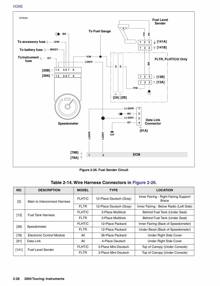
Figure 2-26. Fuel Sender Circuit
Table 2-14. Wire Harness Connectors in Figure 2-26.
NO. DESCRIPTION MODEL TYPE LOCATION
[2] Main to Interconnect HarnessFLHT/C 12-Place Deutsch (Gray)
Inner Fairing - Right Fairing Support Brace
FLTR 12-Place Deutsch (Gray) Inner Fairing - Below Radio (Left Side)
[13] Fuel Tank HarnessFLHT/C 3-Place Multilock Behind Fuel Tank (Under Seat)
FLTR 3-Place Multilock Behind Fuel Tank (Under Seat)
[39] SpeedometerFLHT/C 12-Place Packard Inner Fairing (Back of Speedometer)
FLTR 12-Place Packard Under Bezel (Back of Speedometer)
[78] Electronic Control Module All 36-Place Packard Under Right Side Cover
[91] Data Link All 4-Place Deutsch Under Right Side Cover
[141] Fuel Level SenderFLHT/C 3-Place Mini-Deutsch Top of Canopy (Under Console)
FLTR 3-Place Mini-Deutsch Top of Canopy (Under Console)
1 5
2
2
6
6
9
9
1
1
7
7
5
5
1 2 3
1 2 3
3
1
2
4
1 2 3
1 2 3
5 5
ECM
Data LinkConnector
LG
N/V 12V
GY
[91A]
[78B]
[78A]
LGN/V
BK
Lt GN/V
Lt GN/R
[39B]
[39A]
Speedometer
BK
Fuel Level Sender
BK
To accessory fuse
To Instrument fuse
GY
O/W
LG
N/R
BK
Y/W
To battery fuse BN/GY[141B]
[141A]
Y/W
[13B]
[13A]
To Fuel Gauge
FLTR, FLHT/C/U Only
[2B][2A]
f2208s8x
Y/W
2-28 2004 Touring: Instruments
HOME
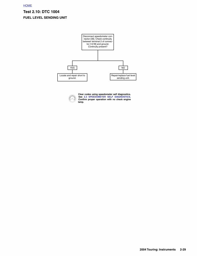
Test 2.10: DTC 1004FUEL LEVEL SENDING UNIT
Disconnect speedometer con-nector [39]. Check continuity
between terminal 2 of connec-tor [141B] and ground.
Continuity present?
Locate and repair short to ground.
Repair/replace fuel level sending unit.
YES NO
Clear codes using speedometer self diagnostics.See 2.3 SPEEDOMETER SELF DIAGNOSTICS.Confirm proper operation with no check enginelamp.
2004 Touring: Instruments 2-29
HOME
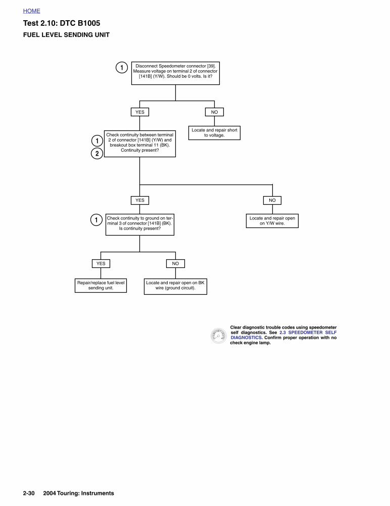
Test 2.10: DTC B1005FUEL LEVEL SENDING UNIT
Check continuity to ground on ter-minal 3 of connector [141B] (BK).
Is continuity present?
YES
Locate and repair open on BK wire (ground circuit).
NO
Repair/replace fuel level sending unit.
1
Disconnect Speedometer connector [39]. Measure voltage on terminal 2 of connector
[141B] (Y/W). Should be 0 volts. Is it?
YES
YES
Locate and repair short to voltage.
NO
Check continuity between terminal 2 of connector [141B] (Y/W) and breakout box terminal 11 (BK).
Continuity present?2
1
Locate and repair open on Y/W wire.
NO
1
Clear diagnostic trouble codes using speedometerself diagnostics. See 2.3 SPEEDOMETER SELFDIAGNOSTICS. Confirm proper operation with nocheck engine lamp.
2-30 2004 Touring: Instruments
HOME
DTC B1006, B1007 2.11
GENERAL
Accessory Or Ignition Line Overvoltage
Ignition and accessory voltage is constantly monitored by thespeedometer (terminal 1-ignition and terminal 6-accessory).If the battery voltage fails to meet normal operating parame-ters, a diagnostic trouble code is set.
● DTC B1006 is displayed when accessory line voltage isgreater than 16.0 volts for longer than 5 seconds.
● DTC B1007 is displayed when ignition line voltage isgreater than 16.0 volts for longer than 5 seconds.
NOTEICM/ECM or TSM/TSSM may also set a battery voltage diag-nostic trouble codes.
Table 2-15. Code Description
DTC DESCRIPTION
B1006 Accessory line overvoltage
B1007 Ignition line overvoltage
2004 Touring: Instruments 2-31
HOME
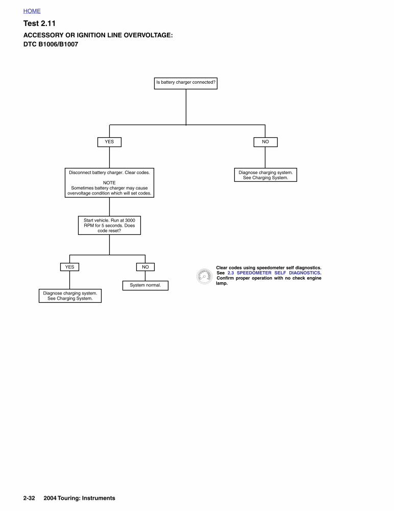
Test 2.11ACCESSORY OR IGNITION LINE OVERVOLTAGE: DTC B1006/B1007
Is battery charger connected?
YES
System normal.
NO
Diagnose charging system. See Charging System.
YES NO
Disconnect battery charger. Clear codes.
NOTESometimes battery charger may cause
overvoltage condition which will set codes.
Start vehicle. Run at 3000 RPM for 5 seconds. Does
code reset?
Diagnose charging system. See Charging System.
Clear codes using speedometer self diagnostics.See 2.3 SPEEDOMETER SELF DIAGNOSTICS.Confirm proper operation with no check enginelamp.
2-32 2004 Touring: Instruments
HOME
DTC B1008 2.12
GENERAL
Reset Switch Closed
DTC B1008 will be set if switch terminals are in a constantshorted state.
DIAGNOSTICS
Diagnostic Notes
The reference numbers below correlate with the circled num-bers on the 2.12 flow chart.
1. Connect BREAKOUT BOX (Part No. HD-42682) andINSTRUMENT HARNESS ADAPTERS (Part No. HD-46601) between wire harness and speedometer, leavingspeedometer disconnected.
Table 2-16. Code Description
DTC DESCRIPTION
B1008 Reset switch closed
2004 Touring: Instruments 2-33

HOME
Figure 2-27. Reset Switch Circuit
Table 2-17. Wire Harness Connectors in Figure 2-27.
NO. DESCRIPTION MODEL TYPE LOCATION
[39] SpeedometerFLHT/C 12-Place Packard Inner Fairing (Back of Speedometer)
FLTR 12-Place Packard Under Bezel (Back of Speedometer)
123456789
101112
d0723x2x
[39B][39A]
BK
Speedometer
Reset Switch
BK
2-34 2004 Touring: Instruments
HOME
Test 2.12
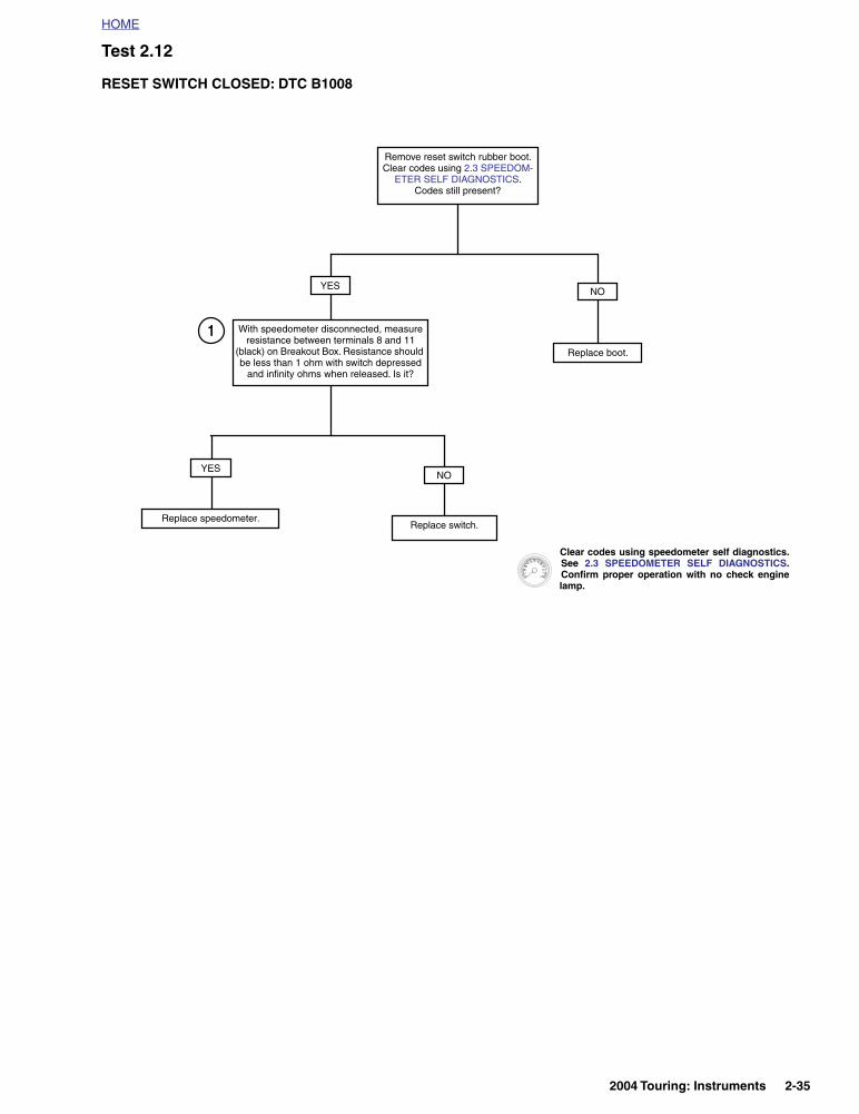
RESET SWITCH CLOSED: DTC B1008
Remove reset switch rubber boot. Clear codes using 2.3 SPEEDOM-
ETER SELF DIAGNOSTICS. Codes still present?
YES
NO
Replace switch.
NO
Replace boot.
YES
Replace speedometer.
1
Clear codes using speedometer self diagnostics.See 2.3 SPEEDOMETER SELF DIAGNOSTICS.Confirm proper operation with no check enginelamp.
With speedometer disconnected, measure resistance between terminals 8 and 11
(black) on Breakout Box. Resistance should be less than 1 ohm with switch depressed
and infinity ohms when released. Is it?
2004 Touring: Instruments 2-35

HOME
DTC U1016 2.13
GENERAL
Loss of ICM/ECM Serial Data
The serial data connector provides a means for the ignitioncontrol module (ICM) or electronic control module (ECM),TSM/TSSM and speedometer to communicate their currentstatus. When all operating parameters on the serial data busare within specifications, a state of health message is sentbetween the components. A DTC U1016 indicates that theICM/ECM is not capable of sending this state of health mes-sage.
DIAGNOSTICS
Diagnostic Notes
The reference numbers below correlate with the circled num-bers on the Test 2.13 flow chart.
1. Connect BREAKOUT BOX (Part No. HD-42682) (gray)between TSM/TSSM connector [30A] and wire harnessconnector [30B]. See 3.11 BREAKOUT BOX: TSM/TSSM.
2. Connect BREAKOUT BOX (Part No. HD-42682) (black)between ICM connector [10A] and wiring harness con-nector [10B]. See 4.6 BREAKOUT BOX: ICM
3. Connect BREAKOUT BOX (Part No. HD-43876)between wire harness and ICM/ECM. See 5.7 BREAK-OUT BOX: EFI.
Table 2-18. Code Description
DTC DESCRIPTION
U1016
Loss of all ICM/ECM serial data (state of health)
Loss of vehicle speed
Loss of vehicle inhibit motion
Loss of powertrain security status
Figure 2-28. Data Link Connector
692414
32
5
1. Terminal 1: flash pin-EFI models (Lt GN/R)2. Terminal 2: ground (BK)3. Terminal 3: serial data (Lt GN/V)4. Terminal 4: power (GY)5. Protective cap
Figure 2-29. Electrical Bracket (Under Right Side Cover)
f2191x8x
Ignition Control ModuleConnector [10]
f1917x9x
Electronic ControlModule Connector [78]Fuel Injected
Carbureted
2-36 2004 Touring: Instruments

HOME
Figure 2-30. Serial Data Circuit: FLHT/C (Carbureted)
Table 2-19. Wire Harness Connectors in Figure 2-30.
NO. DESCRIPTION TYPE LOCATION
[1] Main to Interconnect Harness 12-Place Deutsch (Black) Inner Fairing - Right Radio Support Bracket
[2] Main to Interconnect Harness 12-Place Deutsch (Gray) Inner Fairing - Right Fairing Support Brace
[8] Ignition Harness 12-Place Deutsch Under Right Side Cover
[10] Ignition Control Module 12-Place Deutsch Under Right Side Cover
[30] Turn Signal/Security Module 12-Place DeutschCavity in Crossmember at Rear of
Battery Box (Under Seat)
[39] Speedometer 12-Place Packard Inner Fairing (Back of Speedometer)
[91] Data Link 4-Place Deutsch Under Right Side Cover
[108] Tachometer 12-Place Packard Inner Fairing (Back of Tachometer)
[156] Main to Interconnect Harness 6-Place Deutsch Inner Fairing - Right Fairing Support Brace
12
12
3
1
2
4
321 654 987 121110321 654 987 121110
321 654 987 121110321 654 987 121110
321 654 987 121110321 654 987 121110
1011
127
89
45
61
23
1011
127
89
45
61
23
321 654 987 121110321 654 987 121110
2
43
1
56
2
43
1
56
321 654 987 121110321 654 987 121110
Ignition Control Module
Data Link
TSM/TSSM
LtG
N/V
15AIgnition
Fuse
GY
[8B][8A]
[91A]
LtGN/V
BK
LtGN/V
[39B][39A]
[10B][10A]
Speedometer
O
BK
Ser
ial d
ata
[108B][108A] Tachometer
BN/GY
[156B] [156A]
[30B][30A]
15AAccessory
Fuse
[1B] [1A]
Main to InterconnectHarness
Ignition Harness
Main to InterconnectHarness
f2208z8x
15ABattery
Fuse
[2A][2B]
Main to InterconnectHarness
BK
GY
BN/GY
2004 Touring: Instruments 2-37

HOME
Figure 2-31. Serial Data Circuit: FLHR/S (Carbureted)
Table 2-20. Wire Harness Connectors in Figure 2-31.
NO. DESCRIPTION TYPE LOCATION
[8] Ignition Harness 12-Place Deutsch Under Right Side Cover
[10] Ignition Control Module 12-Place Deutsch Under Right Side Cover
[30] Turn Signal/Security Module 12-Place DeutschCavity in Crossmember at Rear of
Battery Box (Under Seat)
[39] Speedometer 12-Place Packard Under Console (Back of Speedometer)
[91] Data Link 4-Place Deutsch Under Right Side Cover
321 654 987 121110321 654 987 121110
321 654 987 121110321 654 987 121110
321 654 987 121110321 654 987 121110
3
1
2
4
12
12
Data Link
TSM/TSSM
LtG
N/V
GY
[30B][30A]
[91A]
LtGN/V
BK[39B][39A]
[10B][10A]
Speedometer
O
BK
Ser
ial d
ata
Ignition Control Module
BN/GY
15AIgnition
Fuse
15AAccessory
Fuse
LtGN/V
[8B][8A]
Ignition Harness
15ABattery
Fuse
f2208y8x
BK
BN/GY
GY
2-38 2004 Touring: Instruments

HOME
Figure 2-32. Serial Data Circuit: FLTR, FLHT/C/U (Fuel Injected)
Table 2-21. Wire Harness Connectors in Figure 2-32.
NO. DESCRIPTION MODEL TYPE LOCATION
[1]Main to Interconnect Harness
FLHT/C 12-Place Deutsch (Black) Inner Fairing - Right Radio Support Bracket
FLTR 12-Place Deutsch (Black) Inner Fairing - Below Radio (Left Side)
[2]Main to Interconnect Harness
FLHT/C 12-Place Deutsch (Gray) Inner Fairing - Right Fairing Support Brace
FLTR 12-Place Deutsch (Gray) Inner Fairing - Below Radio (Left Side)
[8] Ignition Harness All 12-Place Deutsch Under Right Side Cover
[10] Ignition Control Module All 12-Place Deutsch Under Right Side Cover
[30]Turn Signal/Security Module
All 12-Place DeutschCavity in Crossmember at Rear of
Battery Box (Under Seat)
[39] SpeedometerFLHT/C 12-Place Packard Inner Fairing (Back of Speedometer)
FLTR 12-Place Packard Under Bezel (Back of Speedometer)
[91] Data Link All 4-Place Deutsch Under Right Side Cover
[108] TachometerFLHT/C 12-Place Packard Inner Fairing (Back of Tachometer)
FLTR 12-Place Packard Under Bezel (Back of Tachometer)
[156]Main to Interconnect Harness
FLHT/C 6-Place Deutsch Inner Fairing - Right Fairing Support Brace
FLTR 6-Place Deutsch Inner Fairing - Front of Right Fairing Bracket
51
3
1
2
4
321 654 987 121110321 654 987 121110
321 654 987 121110321 654 987 121110
321 654 987 121110321 654 987 121110
1011
127
89
45
61
23
1011
127
89
45
61
23
321 654 987 121110321 654 987 121110
321 654 987 121110321 654 987 121110
2
43
1
56
2
43
1
56
ECM
Data Link
TSM/TSSM
LtG
N/V
15AIgnition
Fuse
GY
[8B][8A]
[91A]
LtGN/V
BK
LtGN/V
[39B][39A]
[78B][78A]
Speedometer
O
BK
Ser
ial d
ata
[108B][108A]
Tachometer
BN/GY
[156B] [156A]
[30B][30A]
15AAccessory
Fuse
[1B] [1A]
Main to InterconnectHarness
Ignition Harness
Main to InterconnectHarness
f2208u8x
15ABattery
Fuse
[2B][2A]
Main to InterconnectHarness
LtG
N/R
BK
BN/GY
GY
Fla
sh p
in
2004 Touring: Instruments 2-39

HOME
Figure 2-33. Serial Data Circuit: FLHR/C/S (Fuel Injected)
Table 2-22. Wire Harness Connectors in Figure 2-33.
NO. DESCRIPTION TYPE LOCATION
[8] Ignition Harness 12-Place Deutsch Under Right Side Cover
[10] Ignition Control Module 12-Place Deutsch Under Right Side Cover
[30] Turn Signal/Security Module 12-Place DeutschCavity in Crossmember at Rear of
Battery Box (Under Seat)
[39] Speedometer 12-Place Mini-Deutsch Under Console (Back of Speedometer)
[78] Electronic Control Module 36-Place Packard Under Right Side Cover
[91] Data Link 4-Place Deutsch Under Right Side Cover
51
321 654 987 121110321 654 987 121110
321 654 987 121110321 654 987 121110
321 654 987 121110321 654 987 121110
3
1
2
4
f2208t8x
Data Link
TSM/TSSM
LtG
N/V
GY
[30B][30A]
[91A]
LtGN/V
BK[39B][39A]
[78B][78A]
Speedometer
O
BK
ECM
BN/GY
15AIgnition
Fuse
15AAccessory
Fuse
LtGN/V
[8B][8A]
Ignition Harness
15ABattery
Fuse
LtG
N/R
BK
BN/GY
GY
Ser
ial d
ata
Fla
sh p
in
2-40 2004 Touring: Instruments
HOME
Test 2.13
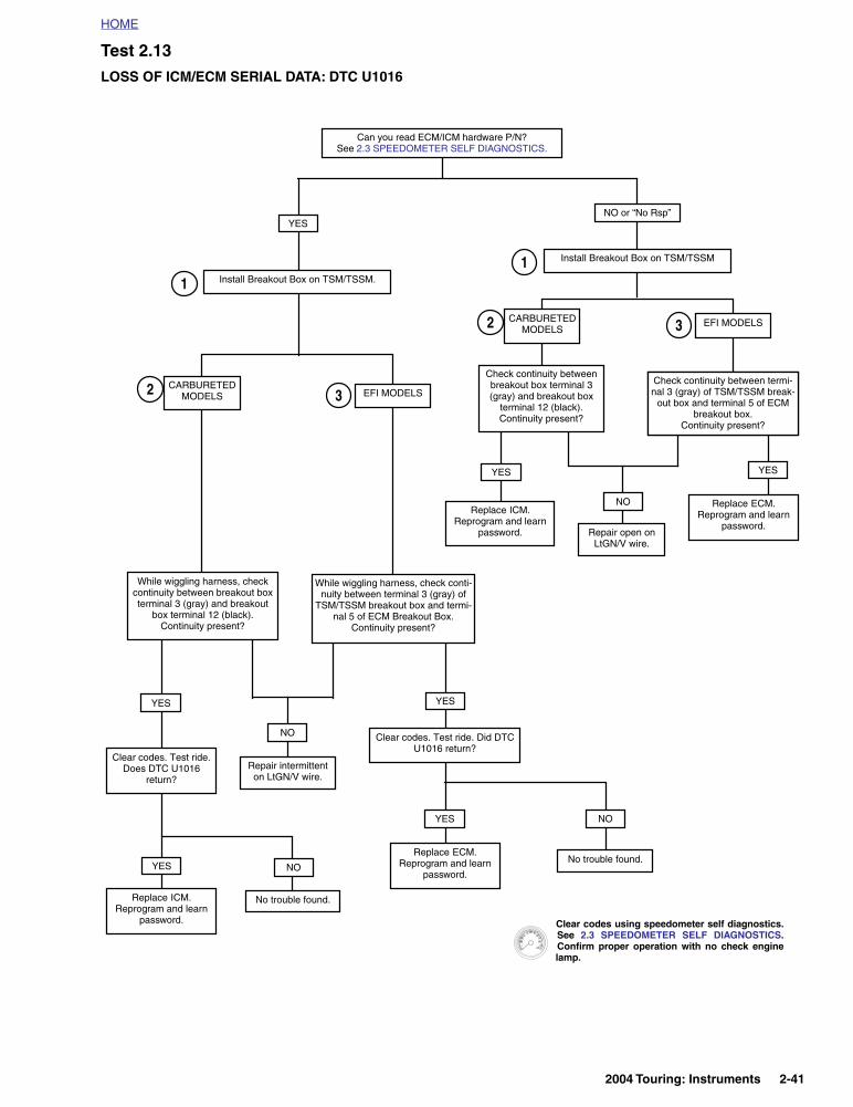
LOSS OF ICM/ECM SERIAL DATA: DTC U1016
Can you read ECM/ICM hardware P/N? See 2.3 SPEEDOMETER SELF DIAGNOSTICS.
NO or “No Rsp”YES
YES
NO
Repair open on LtGN/V wire.
Install Breakout Box on TSM/TSSM1
Replace ICM. Reprogram and learn
password.
CARBURETED MODELS
EFI MODELS
Check continuity between termi-nal 2 (black) of speedometer
Breakout Box and terminal 5 of ECM Breakout Box.Continuity present?
2 3
YES
Replace ECM. Reprogram and learn
password.
Check continuity between termi-nal 3 (gray) of TSM/TSSM break-
out box and terminal 5 of ECM breakout box.
Continuity present?
Install Breakout Box on TSM/TSSM.1
CARBURETED MODELS EFI MODELS2 3
YES
NO
While wiggling harness, check continuity between breakout box terminal 3 (gray) and breakout
box terminal 12 (black).Continuity present?
YES
While wiggling harness, check conti-nuity between terminal 3 (gray) of
TSM/TSSM breakout box and termi-nal 5 of ECM Breakout Box.
Continuity present?
Clear codes. Test ride. Does DTC U1016
return?Repair intermittent on LtGN/V wire.
YES
Replace ICM. Reprogram and learn
password.
NO
No trouble found.
Clear codes. Test ride. Did DTC U1016 return?
Replace ECM. Reprogram and learn
password.
YES NO
No trouble found.
Check continuity between breakout box terminal 3 (gray) and breakout box
terminal 12 (black).Continuity present?
Clear codes using speedometer self diagnostics.See 2.3 SPEEDOMETER SELF DIAGNOSTICS.Confirm proper operation with no check enginelamp.
2004 Touring: Instruments 2-41
HOME
DTC U1064, U1255 2.14
GENERAL
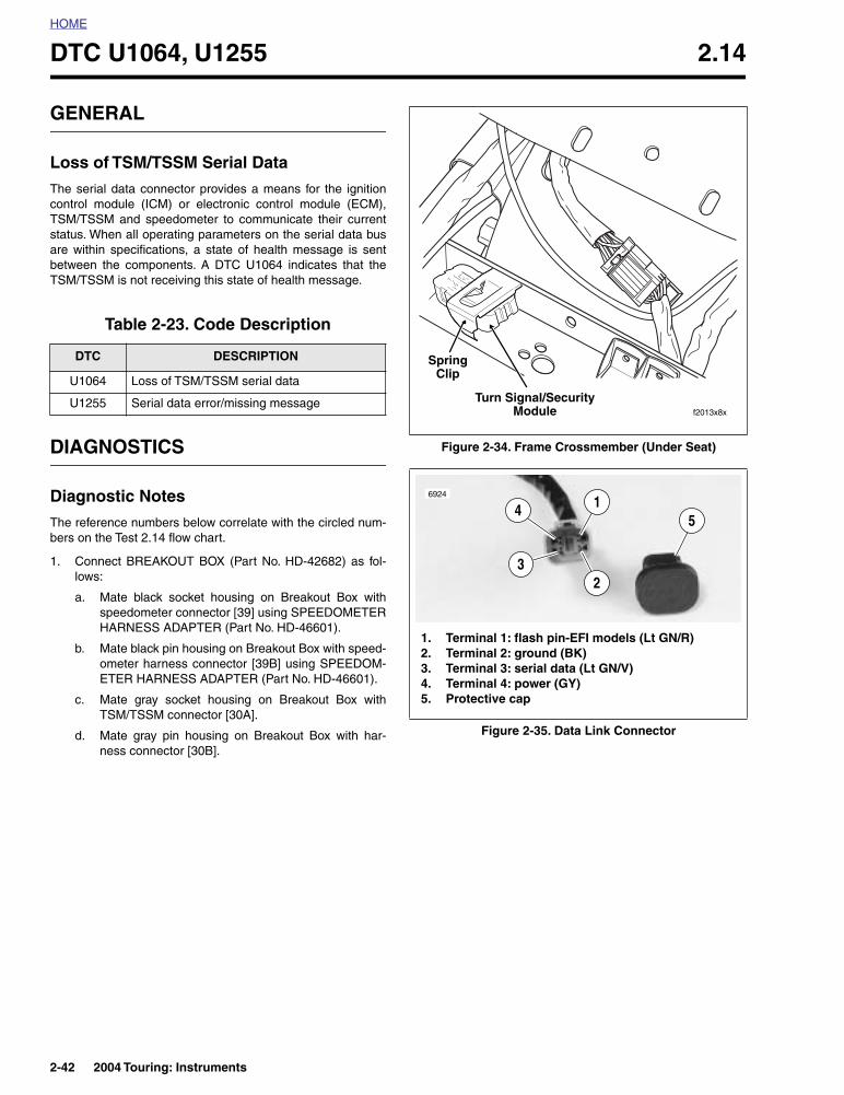
Loss of TSM/TSSM Serial Data
The serial data connector provides a means for the ignitioncontrol module (ICM) or electronic control module (ECM),TSM/TSSM and speedometer to communicate their currentstatus. When all operating parameters on the serial data busare within specifications, a state of health message is sentbetween the components. A DTC U1064 indicates that theTSM/TSSM is not receiving this state of health message.
DIAGNOSTICS
Diagnostic Notes
The reference numbers below correlate with the circled num-bers on the Test 2.14 flow chart.
1. Connect BREAKOUT BOX (Part No. HD-42682) as fol-lows:
a. Mate black socket housing on Breakout Box withspeedometer connector [39] using SPEEDOMETERHARNESS ADAPTER (Part No. HD-46601).
b. Mate black pin housing on Breakout Box with speed-ometer harness connector [39B] using SPEEDOM-ETER HARNESS ADAPTER (Part No. HD-46601).
c. Mate gray socket housing on Breakout Box withTSM/TSSM connector [30A].
d. Mate gray pin housing on Breakout Box with har-ness connector [30B].
Table 2-23. Code Description
DTC DESCRIPTION
U1064 Loss of TSM/TSSM serial data
U1255 Serial data error/missing message
Figure 2-34. Frame Crossmember (Under Seat)
Figure 2-35. Data Link Connector
f2013x8x
Turn Signal/SecurityModule
SpringClip
692414
32
5
1. Terminal 1: flash pin-EFI models (Lt GN/R)2. Terminal 2: ground (BK)3. Terminal 3: serial data (Lt GN/V)4. Terminal 4: power (GY)5. Protective cap
2-42 2004 Touring: Instruments

HOME
Figure 2-36. Serial Data Circuit: FLHT/C (Carbureted)
Table 2-24. Wire Harness Connectors in Figure 2-36.
NO. DESCRIPTION TYPE LOCATION
[1] Main to Interconnect Harness 12-Place Deutsch (Black) Inner Fairing - Right Radio Support Bracket
[2] Main to Interconnect Harness 12-Place Deutsch (Gray) Inner Fairing - Right Fairing Support Brace
[8] Ignition Harness 12-Place Deutsch Under Right Side Cover
[10] Ignition Control Module 12-Place Deutsch Under Right Side Cover
[30] Turn Signal/Security Module 12-Place DeutschCavity in Crossmember at Rear of
Battery Box (Under Seat)
[39] Speedometer 12-Place Packard Inner Fairing (Back of Speedometer)
[91] Data Link 4-Place Deutsch Under Right Side Cover
[108] Tachometer 12-Place Packard Inner Fairing (Back of Tachometer)
[156] Main to Interconnect Harness 6-Place Deutsch Inner Fairing - Right Fairing Support Brace
12
12
3
1
2
4
321 654 987 121110321 654 987 121110
321 654 987 121110321 654 987 121110
321 654 987 121110321 654 987 121110
1011
127
89
45
61
23
1011
127
89
45
61
23
321 654 987 121110321 654 987 121110
2
43
1
56
2
43
1
56
321 654 987 121110321 654 987 121110
Ignition Control Module
Data Link
TSM/TSSM
LtG
N/V
15AIgnition
Fuse
GY
[8B][8A]
[91A]
LtGN/V
BK
LtGN/V
[39B][39A]
[10B][10A]
Speedometer
O
BK
Ser
ial d
ata
[108B][108A] Tachometer
BN/GY
[156B] [156A]
[30B][30A]
15AAccessory
Fuse
[1B] [1A]
Main to InterconnectHarness
Ignition Harness
Main to InterconnectHarness
f2208z8x
15ABattery
Fuse
[2A][2B]
Main to InterconnectHarness
BK
GY
BN/GY
2004 Touring: Instruments 2-43
HOME
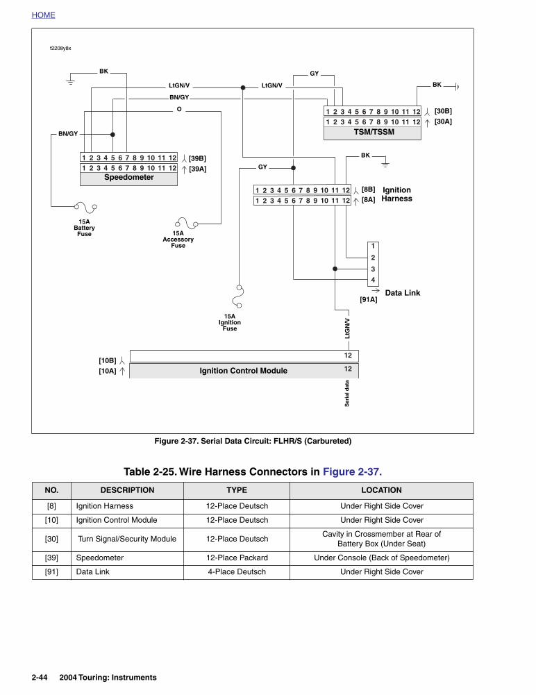
Figure 2-37. Serial Data Circuit: FLHR/S (Carbureted)
Table 2-25. Wire Harness Connectors in Figure 2-37.
NO. DESCRIPTION TYPE LOCATION
[8] Ignition Harness 12-Place Deutsch Under Right Side Cover
[10] Ignition Control Module 12-Place Deutsch Under Right Side Cover
[30] Turn Signal/Security Module 12-Place DeutschCavity in Crossmember at Rear of
Battery Box (Under Seat)
[39] Speedometer 12-Place Packard Under Console (Back of Speedometer)
[91] Data Link 4-Place Deutsch Under Right Side Cover
321 654 987 121110321 654 987 121110
321 654 987 121110321 654 987 121110
321 654 987 121110321 654 987 121110
3
1
2
4
12
12
Data Link
TSM/TSSM
LtG
N/V
GY
[30B][30A]
[91A]
LtGN/V
BK[39B][39A]
[10B][10A]
Speedometer
O
BK
Ser
ial d
ata
Ignition Control Module
BN/GY
15AIgnition
Fuse
15AAccessory
Fuse
LtGN/V
[8B][8A]
Ignition Harness
15ABattery
Fuse
f2208y8x
BK
BN/GY
GY
2-44 2004 Touring: Instruments

HOME
Figure 2-38. Serial Data Circuit: FLTR, FLHT/C/U (Fuel Injected)
Table 2-26. Wire Harness Connectors in Figure 2-38.
NO. DESCRIPTION MODEL TYPE LOCATION
[1]Main to Interconnect Harness
FLHT/C 12-Place Deutsch (Black) Inner Fairing - Right Radio Support Bracket
FLTR 12-Place Deutsch (Black) Inner Fairing - Below Radio (Left Side)
[2]Main to Interconnect Harness
FLHT/C 12-Place Deutsch (Gray) Inner Fairing - Right Fairing Support Brace
FLTR 12-Place Deutsch (Gray) Inner Fairing - Below Radio (Left Side)
[8] Ignition Harness All 12-Place Deutsch Under Right Side Cover
[10] Ignition Control Module All 12-Place Deutsch Under Right Side Cover
[30]Turn Signal/Security Module
All 12-Place DeutschCavity in Crossmember at Rear of
Battery Box (Under Seat)
[39] SpeedometerFLHT/C 12-Place Packard Inner Fairing (Back of Speedometer)
FLTR 12-Place Packard Under Bezel (Back of Speedometer)
[91] Data Link All 4-Place Deutsch Under Right Side Cover
[108] TachometerFLHT/C 12-Place Packard Inner Fairing (Back of Tachometer)
FLTR 12-Place Packard Under Bezel (Back of Tachometer)
[156]Main to Interconnect Harness
FLHT/C 6-Place Deutsch Inner Fairing - Right Fairing Support Brace
FLTR 6-Place Deutsch Inner Fairing - Front of Right Fairing Bracket
51
3
1
2
4
321 654 987 121110321 654 987 121110
321 654 987 121110321 654 987 121110
321 654 987 121110321 654 987 121110
1011
127
89
45
61
23
1011
127
89
45
61
23
321 654 987 121110321 654 987 121110
321 654 987 121110321 654 987 121110
2
43
1
56
2
43
1
56
ECM
Data Link
TSM/TSSM
LtG
N/V
15AIgnition
Fuse
GY
[8B][8A]
[91A]
LtGN/V
BK
LtGN/V
[39B][39A]
[78B][78A]
Speedometer
O
BK
[108B][108A]
Tachometer
BN/GY
[156B] [156A]
[30B][30A]
15AAccessory
Fuse
[1B] [1A]
Main to InterconnectHarness
Ignition Harness
Main to InterconnectHarness
f2208u8x
15ABattery
Fuse
[2B][2A]
Main to InterconnectHarness
LtG
N/R
BK
BN/GY
GY
Ser
ial d
ata
Fla
sh p
in
2004 Touring: Instruments 2-45

HOME
Figure 2-39. Serial Data Circuit: FLHR/C/S (Fuel Injected)
Table 2-27. Wire Harness Connectors in Figure 2-39.
NO. DESCRIPTION TYPE LOCATION
[8] Ignition Harness 12-Place Deutsch Under Right Side Cover
[10] Ignition Control Module 12-Place Deutsch Under Right Side Cover
[30] Turn Signal/Security Module 12-Place DeutschCavity in Crossmember at Rear of
Battery Box (Under Seat)
[39] Speedometer 12-Place Mini-Deutsch Under Console (Back of Speedometer)
[78] Electronic Control Module 36-Place Packard Under Right Side Cover
[91] Data Link 4-Place Deutsch Under Right Side Cover
51
321 654 987 121110321 654 987 121110
321 654 987 121110321 654 987 121110
321 654 987 121110321 654 987 121110
3
1
2
4
f2208t8x
Data Link
TSM/TSSM
LtG
N/V
GY
[30B][30A]
[91A]
LtGN/V
BK[39B][39A]
[78B][78A]
Speedometer
O
BK
ECM
BN/GY
15AIgnition
Fuse
15AAccessory
Fuse
LtGN/V
[8B][8A]
Ignition Harness
15ABattery
Fuse
LtG
N/R
BK
BN/GY
GY
Ser
ial d
ata
Fla
sh p
in
2-46 2004 Touring: Instruments
HOME
Test 2.14
LOSS OF TSM/TSSM SERIAL DATA: DTC U1064, U1255
Can you read TSM/TSSM hardware P/N? See 2.3 SPEEDOMETER SELF DIAGNOSTICS.
NO or “No Rsp”YES
YESNO
Repair open on LtGN/V wire.
Install Breakout Box on speedometer.Check for continuity between terminal 3 (gray) and terminal 2 (black) of Breakout
Box Continuity present?
1Install Breakout Box on speedometer.While wiggling harness, check for continuity
between terminal 3 (gray) and terminal 2 (black) of Breakout Box.
Continuity present?
YES
Repair intermittent on LtGN/V wire.
NO
1
Clear codes. Test ride. Does DTC U1064
return?
YES NO
No trouble found.
Replace TSM/TSSM. Learn password.
Replace TSM/TSSM. Learn password.
Clear codes using speedometer self diagnostics.See 2.3 SPEEDOMETER SELF DIAGNOSTICS.Confirm proper operation with no check enginelamp.
2004 Touring: Instruments 2-47
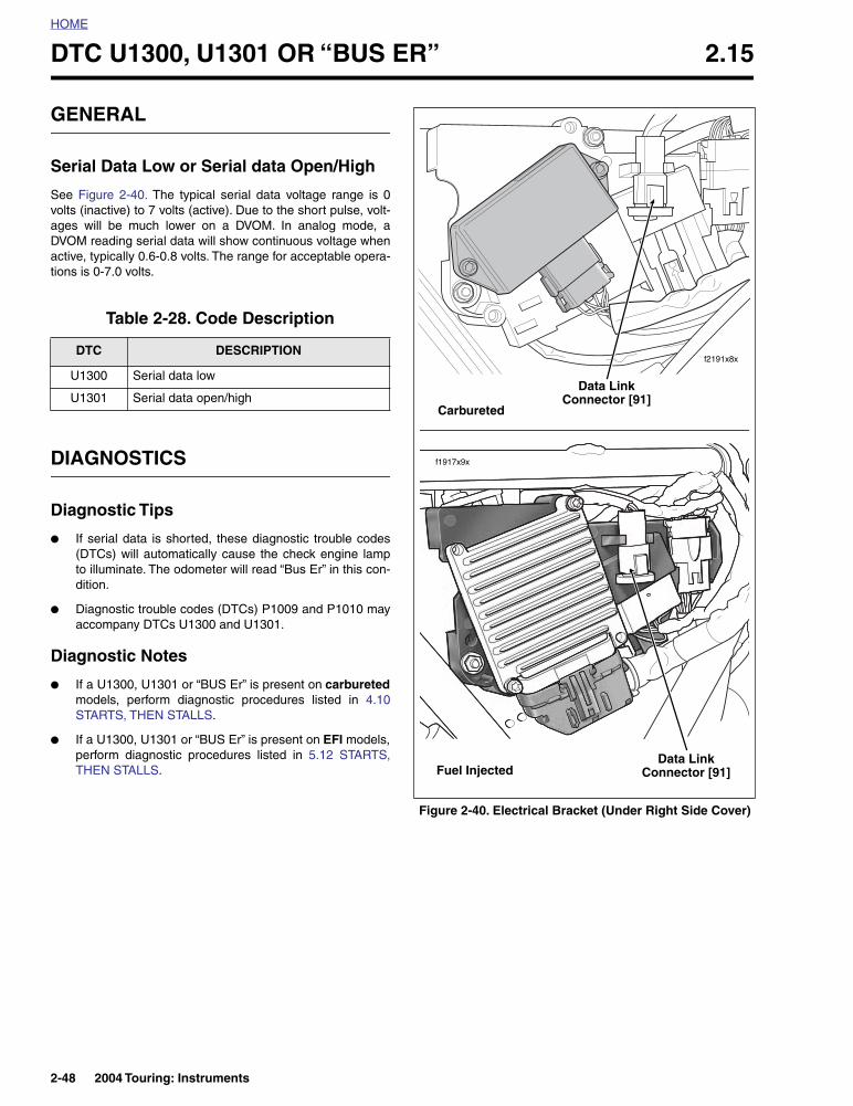
HOME
DTC U1300, U1301 OR “BUS ER” 2.15
GENERAL
Serial Data Low or Serial data Open/High
See Figure 2-40. The typical serial data voltage range is 0volts (inactive) to 7 volts (active). Due to the short pulse, volt-ages will be much lower on a DVOM. In analog mode, aDVOM reading serial data will show continuous voltage whenactive, typically 0.6-0.8 volts. The range for acceptable opera-tions is 0-7.0 volts.
DIAGNOSTICS
Diagnostic Tips
● If serial data is shorted, these diagnostic trouble codes(DTCs) will automatically cause the check engine lampto illuminate. The odometer will read “Bus Er” in this con-dition.
● Diagnostic trouble codes (DTCs) P1009 and P1010 mayaccompany DTCs U1300 and U1301.
Diagnostic Notes
● If a U1300, U1301 or “BUS Er” is present on carburetedmodels, perform diagnostic procedures listed in 4.10STARTS, THEN STALLS.
● If a U1300, U1301 or “BUS Er” is present on EFI models,perform diagnostic procedures listed in 5.12 STARTS,THEN STALLS.
Table 2-28. Code Description
DTC DESCRIPTION
U1300 Serial data low
U1301 Serial data open/high
Figure 2-40. Electrical Bracket (Under Right Side Cover)
f2191x8x
Data LinkConnector [91]
f1917x9x
Data LinkConnector [91]Fuel Injected
Carbureted
2-48 2004 Touring: Instruments