2003 Amendments to the Protocol of 1988 Relating to the ... · PDF fileTreaty Series No. 4...
60
Treaty Series No. 4 (2006) 2003 Amendments to the Protocol of 1988 Relating to the International Convention on Load Lines, 1966 London, 5 June 2003 [The Amendments entered into force on 1 January 2005] Presented to Parliament by the Secretary of State for Foreign and Commonwealth AVairs by Command of Her Majesty March 2006 Cm 6756 £10.50
Transcript of 2003 Amendments to the Protocol of 1988 Relating to the ... · PDF fileTreaty Series No. 4...

Treaty Series No. 4 (2006)
2003 Amendments to theProtocol of 1988 Relating to the
International Convention onLoad Lines, 1966
London, 5 June 2003
[The Amendments entered into force on 1 January 2005]
Presented to Parliamentby the Secretary of State for Foreign and Commonwealth AVairs
by Command of Her MajestyMarch 2006
Cm 6756 £10.50

A Crown Copyright 2006
The text in this document (excluding the Royal Arms and departmental logos) may be
reproduced free of charge in any format or medium providing it is reproduced accurately
and not used in a misleading context. The material must be acknowledged as Crown
copyright and the title of the document specified.
Any enquiries relating to the copyright in this document should be addressed to
The Licensing Division, HMSO, St Clements House, 2–16 Colegate, Norwich NR3 1BQ.
Fax: 01603 723000 or e-mail: licensingwcabinet-oYce.x.gsi.gov.uk

ANNEX
AMENDMENTS TO ANNEX B TO THE PROTOCOL OF 1988 RELATING TO THEINTERNATIONAL CONVENTION ON LOAD LINES, 1966
1 The existing text of Annex I to Annex B is replaced by the following:
“ANNEX IREGULATIONS FOR DETERMINING LOAD LINES
Chapter I
General
The regulations assume that the nature and stowage of the cargo, ballast, etc., are such asto secure suYcient stability of the ship and the avoidance of excessive structural stress.
The regulations also assume that where there are international requirements relating tostability or subdivision, these requirements have been complied with.
Regulation 1
Strength and intact stability of ships
(1) The Administration shall satisfy itself that the general structural strength of the shipis adequate for the draught corresponding to the freeboard assigned.
(2) A ship which is designed, constructed and maintained in compliance with theappropriate requirements of an organization, including a classification society, whichis recognized by the Administration or with applicable national standards of theAdministration in accordance with the provisions of regulation 2-1, may beconsidered to provide an acceptable level of strength. The above provisions shallapply to all structures, equipment and fittings covered by this annex for whichstandards for strength and construction are not expressly provided.
(3) Ships shall comply with an intact stability standard acceptable to the Administration.
Regulation 2
Application
(1) Ships with mechanical means of propulsion or lighters, barges or other ships withoutindependent means of propulsion, shall be assigned freeboards in accordance with theprovisions of regulations 1 to 40, inclusive.
(2) Ships carrying timber deck cargoes may be assigned, in addition to freeboardsprescribed in paragraph (1), timber freeboards in accordance with the provisions ofregulations 41 to 45.
(3) Ships designed to carry sail, whether as the sole means of propulsion or as asupplementary means, and tugs, shall be assigned freeboards in accordance with theprovisons of regulations 1 to 40, inclusive. Additional freeboard may be required asdetermined by the Administration.
(4) Ships of wood or of composite construction, or of other materials the use of whichthe Administration has approved, or ships whose constructional features are such asto render the application of the provisions of this Annex unreasonable orimpracticable, shall be assigned freeboards as determined by the Administration.
3

(5) Regulations 10 to 26, inclusive, shall apply to every ship to which a minimumfreeboard is assigned. Relaxations from these requirements may be granted to a shipto which a greater than minimum freeboard is assigned, on condition that theAdministration is satisfied with the safety conditions provided.
(6) Where the assigned summer freeboard is increased such that the resulting draught isnot more than that corresponding to a minimum summer freeboard for the same ship,but with an assumed freeboard deck located a distance below the actual freeboarddeck at least equal to the standard superstructure height, the conditions of assignmentin accordance with regulations 12, 14-1 through 20, 23, 24 and 25, as applicable, tothe actual freeboard deck may be as required for a superstructure deck.
(7) Unless expressly provided otherwise, the regulations of this Annex shall apply to shipsthe keels of which are laid or which are at a similar stage of construction on or after1 January 2005.
(8) For ships the keels of which are laid or which are at a similar stage of constructionbefore 1 January 2005, the Administration shall ensure that the requirements whichare applicable under the International Convention on Load Lines, 1966,1 as modifiedby the Protocol of 19882 relating thereto, adopted by the International Conference onHarmonized System of Survey and Certification, 1988, are complied with.
(9) High-speed craft which comply with the requirements of the International Code ofSafety for High-Speed Craft, 2000 (2000 HSC Code), adopted by the Maritime SafetyCommittee of the Organization by resolution MSC.97(73) and which have beensurveyed and certified as provided in the Code shall be deemed to have complied withthe requirements of this Annex. The certificates and permits issued under the 2000HSC Code shall have the same force and the same recognition as the certificates issuedunder this Annex.
Regulation 2-1
Authorization of recognized organizations
Organizations, including classification societies, referred to in article 13 of the Conventionand regulation 1(2) shall comply with the guidelines adopted by the Organization byresolution A.739(18), as may be amended by the Organization, and the specificationsadopted by the Organization by resolution A.789(19), as may be amended by theOrganization, provided that such amendments are adopted, brought into force and takeeVect in accordance with the provisions of article VI of the present Protocol.
Regulation 3
Definitions of terms used in the Annexes
(1) Length
(a) The length (L) shall be taken as 96% of the total length on a waterline at 85% ofthe least moulded depth measured from the top of the keel, or as the length fromthe fore-side of the stem to the axis of the rudder stock on that waterline, if that begreater.
(b) For ships without a rudder stock, the length (L) is to be taken as 96% of thewaterline at 85% of the least moulded depth.
(c) Where the stem contour is concave above the waterline at 85% of the least mouldeddepth, both the forward terminal of the total length and the fore-side of the stemrespectively shall be taken at the vertical projection to that waterline of theaftermost point to the stem contour (above that waterline) (see figure 3.1).
(d) In ships designed with a rake of keel the waterline on which this length is measured
1Treaty Series No. 58 (1968) Cmnd 37082Treaty Series No. 100 (2000) Cm 4829
4
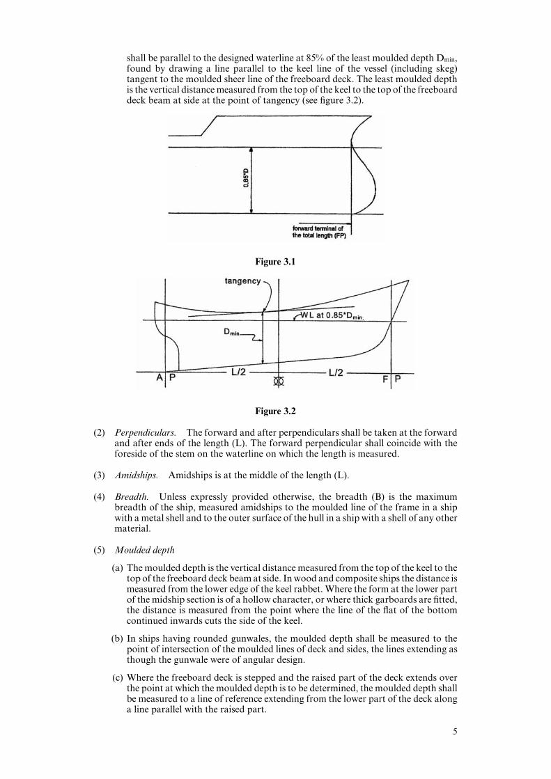
shall be parallel to the designed waterline at 85% of the least moulded depth Dmin,found by drawing a line parallel to the keel line of the vessel (including skeg)tangent to the moulded sheer line of the freeboard deck. The least moulded depthis the vertical distance measured from the top of the keel to the top of the freeboarddeck beam at side at the point of tangency (see figure 3.2).
Figure 3.1
Figure 3.2
(2) Perpendiculars. The forward and after perpendiculars shall be taken at the forwardand after ends of the length (L). The forward perpendicular shall coincide with theforeside of the stem on the waterline on which the length is measured.
(3) Amidships. Amidships is at the middle of the length (L).
(4) Breadth. Unless expressly provided otherwise, the breadth (B) is the maximumbreadth of the ship, measured amidships to the moulded line of the frame in a shipwith a metal shell and to the outer surface of the hull in a ship with a shell of any othermaterial.
(5) Moulded depth
(a) The moulded depth is the vertical distance measured from the top of the keel to thetop of the freeboard deck beam at side. In wood and composite ships the distance ismeasured from the lower edge of the keel rabbet. Where the form at the lower partof the midship section is of a hollow character, or where thick garboards are fitted,the distance is measured from the point where the line of the flat of the bottomcontinued inwards cuts the side of the keel.
(b) In ships having rounded gunwales, the moulded depth shall be measured to thepoint of intersection of the moulded lines of deck and sides, the lines extending asthough the gunwale were of angular design.
(c) Where the freeboard deck is stepped and the raised part of the deck extends overthe point at which the moulded depth is to be determined, the moulded depth shallbe measured to a line of reference extending from the lower part of the deck alonga line parallel with the raised part.
5

(6) Depth for freeboard (D)
(a) The depth for freeboard (D) is the moulded depth amidships, plus the freeboarddeck thickness at side.
(b) The depth for freeboard (D) in a ship having a rounded gunwale with a radiusgreater than 4% of the breadth (B) or having topsides of unusual form is the depthfor freeboard of a ship having a midship section with vertical topsides and with thesame round of beam and area of topside section equal to that provided by theactual midship section.
(7) Block coeYcient
(a) The block coeYcient (Cb) is given by:
nCb% ; where
L ·B · d1
n is the volume of the moulded displacement of the ship, excluding appendages,in a ship with a metal shell, and is the volume of displacement to the outer surfaceof the hull in a ship with a shell of any other material, both taken at a mouldeddraught of d1; and where
d1 is 85% of the least moulded depth.
(b) When calculating the block coeYcient of a multi-hull craft, the full breadth (B) asdefined in paragraph (4) is to be used and not the breadth of a single hull.
(8) Freeboard. The freeboard assigned is the distance measured vertically downwardsamidships from the upper edge of the deck line to the upper edge of the relatedload line.
(9) Freeboard deck
(a) The freeboard deck is normally the uppermost complete deck exposed to weatherand sea, which has permanent means of closing all openings in the weather partthereof, and below which all openings in the sides of the ship are fitted withpermanent means of watertight closing.
(b) Lower deck as a freeboard deck
At the option of the owner and subject to the approval of the Administration, alower deck may be designated as the freeboard deck provided it is a complete andpermanent deck continuous in a fore and aft direction at least between themachinery space and peak bulkheads and continuous athwartships.
(i) When this lower deck is stepped the lowest line of the deck and thecontinuation of that line parallel to the upper part of the deck is taken as thefreeboard deck.
(ii) When a lower deck is designated as the freeboard deck, that part of the hullwhich extends above the freeboard deck is treated as a superstructure so faras concerns the application of the conditions of assignment and thecalculation of freeboard. It is from this deck that the freeboard is calculated.
(iii) When a lower deck is designated as the freeboard deck, such deck as aminimum shall consist of suitably framed stringers at the ship sides andtransversely at each watertight bulkhead which extends to the upper deck,within cargo spaces. The width of these stringers shall not be less than can beconveniently fitted having regard to the structure and the operation of theship. Any arrangement of stringers shall be such that structural requirementscan also be met.
(c) Discontinuous freeboard deck, stepped freeboard deck
(i) Where a recess in the freeboard deck extends to the sides of the ship and isin excess of one metre in length, the lowest line of the exposed deck and thecontinuation of that line parallel to the upper part of the deck is taken as thefreeboard deck (see figure 3.3).
6
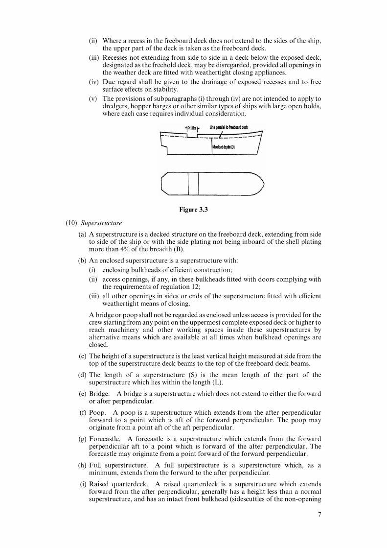
(ii) Where a recess in the freeboard deck does not extend to the sides of the ship,the upper part of the deck is taken as the freeboard deck.
(iii) Recesses not extending from side to side in a deck below the exposed deck,designated as the freehold deck, may be disregarded, provided all openings inthe weather deck are fitted with weathertight closing appliances.
(iv) Due regard shall be given to the drainage of exposed recesses and to freesurface eVects on stability.
(v) The provisions of subparagraphs (i) through (iv) are not intended to apply todredgers, hopper barges or other similar types of ships with large open holds,where each case requires individual consideration.
Figure 3.3
(10) Superstructure
(a) A superstructure is a decked structure on the freeboard deck, extending from sideto side of the ship or with the side plating not being inboard of the shell platingmore than 4% of the breadth (B).
(b) An enclosed superstructure is a superstructure with:
(i) enclosing bulkheads of eYcient construction;
(ii) access openings, if any, in these bulkheads fitted with doors complying withthe requirements of regulation 12;
(iii) all other openings in sides or ends of the superstructure fitted with eYcientweathertight means of closing.
A bridge or poop shall not be regarded as enclosed unless access is provided for thecrew starting from any point on the uppermost complete exposed deck or higher toreach machinery and other working spaces inside these superstructures byalternative means which are available at all times when bulkhead openings areclosed.
(c) The height of a superstructure is the least vertical height measured at side from thetop of the superstructure deck beams to the top of the freeboard deck beams.
(d) The length of a superstructure (S) is the mean length of the part of thesuperstructure which lies within the length (L).
(e) Bridge. A bridge is a superstructure which does not extend to either the forwardor after perpendicular.
(f) Poop. A poop is a superstructure which extends from the after perpendicularforward to a point which is aft of the forward perpendicular. The poop mayoriginate from a point aft of the aft perpendicular.
(g) Forecastle. A forecastle is a superstructure which extends from the forwardperpendicular aft to a point which is forward of the after perpendicular. Theforecastle may originate from a point forward of the forward perpendicular.
(h) Full superstructure. A full superstructure is a superstructure which, as aminimum, extends from the forward to the after perpendicular.
(i) Raised quarterdeck. A raised quarterdeck is a superstructure which extendsforward from the after perpendicular, generally has a height less than a normalsuperstructure, and has an intact front bulkhead (sidescuttles of the non-opening
7

type fitted with eYcient deadlights and bolted man hole covers) (see figure 3.4).Where the forward bulkhead is not intact due to doors and access openings, thesuperstructure is then to be considered as a poop.
Figure 3.4
(11) Superstructure deck. A superstructure deck is a deck forming the upper boundaryof a superstructure.
(12) Flush deck ship. A flush deck ship is a ship which has no superstructure on thefreeboard deck.
(13) Weathertight. Weathertight means that in any sea conditions water will notpenetrate into the ship.
(14) Watertight. Watertight means capable of preventing the passage of water throughthe structure in either direction with a proper margin of resistance under the pressuredue to the maximum head of water which it might have to sustain.
(15) Well. A well is any area on the deck exposed to the weather, where water may beentrapped. Wells are considered to be deck areas bounded on two or more sides bydeck structures.
Regulation 4
Deck line
The deck line is a horizontal line 300 mm in length and 25 mm in breadth. It shall be markedamidships on each side of the ship, and its upper edge shall normally pass through the pointwhere the continuation outwards of the upper surface of the freeboard deck intersects theouter surface of the shell (as illustrated in figure 4.1), provided that the deck line may beplaced with reference to another fixed point on the ship on condition that the freeboard iscorrespondingly corrected. The location of the reference point and the identification of thefreeboard deck shall in all cases be indicated on the International Load Line Certificate.
Figure 4.1 Deck line
8
Regulation 5
Load line mark
The load line mark shall consist of a ring 300 mm in outside diameter and 25 mm widewhich is intersected by a horizontal line 450 mm in length and 25 mm in breadth, the upperedge of which passes through the centre of the ring. The centre of the ring shall be placedamidships and at a distance equal to the assigned summer freeboard measure verticallybelow the upper edge of the deck line (as illustrated in figure 6.1).
Regulation 6
Lines to be used with the load line mark
(1) The lines which indicate the load line assigned in accordance with these regulationsshall be horizontal lines 230 mm in length and 25 mm in breadth which extend forwardof, unless expressly provided otherwise, and at right angles to, a vertical line 25 mmin breadth marked at a distance 540 mm forward of the centre of the ring (asillustrated in figure 6.1).
(2) The following load lines shall be used:
(a) The Summer Load Line indicated by the upper edge of the line which passesthrough the centre of the ring and also by a line marked S.
(b) The Winter Load Line indicated by the upper edge of a line marked W.
(c) The Winter North Atlantic Load Line indicated by the upper edge of a line markedWNA.
(d) The Tropical Load Line indicated by the upper edge of a line marked T.
(e) The Fresh Water Load Line in summer indicated by the upper edge of a linemarked F. The Fresh Water Load Line in summer is marked abaft the vertical line.The diVerence between the Fresh Water Load Line in summer and the SummerLoad Line is the allowance to be made for loading in fresh water at the other loadlines.
(f) The Tropical Fresh Water Load Line indicated by the upper edge of a line markedTF and marked abaft the vertical line.
(3) If timber freeboards are assigned in accordance with these regulations, the timber loadlines shall be marked in addition to ordinary load lines. These lines shall be horizontallines 230 mm in length and 25 mm in breadth which extended abaft, unless expresslyprovided otherwise, and are at right angles to a vertical line 25 mm in breadth markedat a distance 540 mm abaft the centre of the ring (as illustrated in figure 6.2).
(4) The following timber load lines shall be used:
(a) The Summer Timber Load Line indicated by the upper edge of a line marked LS.
(b) The Winter Timber Load Line indicated by the upper edge of a line marked LW.
(c) The Winter North Atlantic Timber Load Line indicated by the upper edge of a linemarked LWNA.
(d) The Tropical Timber Load Line indicated by the upper edge of a line marked LT.
(e) The Fresh Water Timber Load Line in summer indicated by the upper edge of aline marked LF and marked forward of the vertical line. The diVerence btween theFresh Water Timber Load Line in summer and the Summer Timber Load Line isthe allowance to be made for loading in fresh water at the other timber load lines.
(f) The Tropical Fresh Water Timber Load Line indicated by the upper edge of a linemarked LTF and marked forward of the vertical line.
9

(5) Where the characteristics of a ship or the nature of the ship’s service of navigationallimits make any of the seasonal lines inapplicable, these lines may be omitted.
(6) Where a ship is assigned a greater than minimum freeboard so that the load line ismarked at a position corresponding to, or lower than, the lowest seasonal load lineassigned at minimum freeboard in accordance with the present Protocol, only theFresh Water Load Line need be marked.
(7) Where a Winter North Atlantic Load Line is identical with the Winter Load Linecorresponding to the same vertical line, this load line shall be marked W.
(8) Alternative/additional load lines required by other international conventions in forcemay be marked at right angles to and abaft the vertical line specified in paragraph (1).
Figure 6.1 Load line mark and lines to be used with this mark
Figure 6.2 Timber load line mark and lines to be used with this mark
Regulation 7
Mark of assigning Authority
The mark of the Authority by whom the load lines are assigned may be indicated alongsidethe load line ring above the horizontal line which passes through the centre of the ring,or above and below it. This mark shall consist of not more than four initials to identifythe Authority’s name, each measuring approximately 115 mm in height and75 mm in width.
10
Regulation 8
Details of marking
The ring, lines and letters shall be painted in white or yellow on a dark ground or in blackon a light ground. They shall also be permanently marked on the sides of the ships to thesatisfaction of the Administration. The marks shall be plainly visible and, if necessary,special arrangements shall be made for this purpose.
Regulation 9
Verification of marks
The International Load Line Certificate shall not be delivered to the ship until the oYceror surveyor acting under the provisions of article 13 of the Convention has certified thatthe marks are correctly and permanently indicated on the ship’s sides.
CHAPTER II
Conditions of Assignment of Freeboard
Regulation 10
Information to be supplied to the master
(1) The master of every new ship shall be supplied with information to arrange for theloading and ballasting of his ship in such a way as to avoid the creation of anyunacceptable stresses in the ship’s structure, provided that this requirement need notapply to any particular length, design or class of ship where the Administrationconsiders it to be unnecessary.
(2) Information shall be provided to the master in a form that is approved by theAdministration or a recognised organization. Stability information, and loadinginformation also related to ship strength when required under paragraph (1), shall becarried on board at all times together with evidence that the information has beenapproved by the Administration.
(3) A ship which is not required under the International Convention for Safety of Life atSea1 in force to undergo an inclining test upon its completion shall:
(a) be so inclined and the actual displacement and position of the centre of gravityshall be determined for the lightship condition;
(b) if the Administration so approves, have its inclining test on completion dispensedwith, provided basic stability data are available from the inclining test of a sistership and it is shown to the satisfaction of the Administration that reliable stabilityinformation for the ship can be obtained from such basic data;
(c) if the Administration decides that the performance of an inclining test is notpracticable or safe or yields inaccurate results due to the specific proportions,arrangements, strength or hull form of a ship, have the ship’s lightshipcharacteristics determined by a detailed weight estimate confirmed by a lightweightsurvey;
(d) have such information supplied for the use of its master as is necessary to enablethe master, by rapid and simple processes, to obtain accurate guidance as to thestability of the ship under all conditions likely to be encountered in normal service;and
(e) carry on board at all times its approved stability information together withevidence that the information has been approved by the Administration.
1Treaty Series No. 46 (1980) Cmnd 7874.
11

(4) Where any alterations are made to a ship so as to materially aVect the loading orstability information supplied to the master, amended information shall be provided.If necessary the ship shall be re-inclined.
Regulation 11
Superstructure end bulkheads
Bulkheads at exposed ends of enclosed superstructures shall be of an acceptable level ofstrength.
Regulation 12
Doors
(1) All access openings in bulkheads at ends of enclosed superstructures shall be fittedwith doors of steel or other equivalent material, permanently and strongly attachedto the bulkhead, and framed, stiVened and fitted so that the whole structure is ofequivalent strength to the un-pierced bulkhead and weathertight when closed. Themeans for securing these doors weathertight shall consist of gaskets and clampingdevices or other equivalent means and shall be permanently attached to the bulkheador to the doors themselves, and the doors shall be so arranged that they can beoperated from both sides of the bulkhead.
(2) Unless otherwise permitted by the Administration, doors shall open outwards toprovide additional security against the impact of the sea.
(3) Except as otherwise provided in these regulations, the height of the sills of accessopenings in bulkheads at ends of enclosed superstructures shall be at least 380 mmabove the deck.
(4) Portable sills shall be avoided. However, in order to facilitate the loading/unloadingof heavy spare parts or similar, portable sills may be fitted on the following conditions:
(a) they shall be installed before the ship leaves port; and
(b) they shall be gasketed and fastened by closely spaced through bolts.
Regulation 13
Position of hatchways, doorways and ventilators
For the purpose of these regulations, two positions of hatchways, doorways and ventilatorsare defined as follows:
Position 1 — Upon exposed freeboard and raised quarter decks, and upon exposedsuperstructure decks situated forward of a point located a quarter of theship’s length from the forward perpendicular.
Position 2 — Upon exposed superstructure decks situated abaft a quarter of the ship’slength from the forward perpendicular and located at least one standardheight of superstructure above the freeboard deck.
Upon exposed superstructure decks situated forward of a point located aquarter of the ship’s length from the forward perpendicular and located atleast two standard heights of superstructure above the freeboard deck.
12
Regulation 14
Cargo and other hatchways
(1) The construction and means for securing the weathertightness of cargo and otherhatchways in position 1 and 2 shall be at least equivalent to the requirements ofregulation 16, unless the application of regulation 15 to such hatchways is granted bythe Administration.
(2) Coamings and hatchway covers to exposed hatchways on decks above thesuperstructure deck shall comply with the requirements of the Administration.
Regulation 14-1
Hatchway coamings
(1) The coamings of hatchways shall be of substantial construction in accordance withtheir position, and their height above the deck shall be at least as follows:
(a) 600 mm if in position 1; and
(b) 450 mm if in position 2.
(2) In the case of hatchways which comply with regulation 16(2) through (5), the heightof these coamings may be reduced, or the coamings omitted entirely, on condition thatthe Administration is satisfied that the safety of the ship is not thereby impaired inany sea conditions.
Regulation 15
Hatchways closed by portable covers and secured weathertight by tarpaulinsand battening devices
Hatchway covers
(1) The width of each bearing surface for hatchway covers shall be at least 65 mm.
(2) Where covers are made of wood, the finished thickness shall be at least 60 mm inassociation with a span of not more than 1.5 m.
(3) Where covers are made of mild steel the strength shall be calculated in accordancewith the requirement of regulation 16(2) to (4) and the product of the maximum stressthus calculated and the factor 1.25 shall not exceed the minimum upper yield pointstrength of the material. They shall be so designed as to limit the deflection to not morethan 0.0056 times the span under these loads.
Portable beams
(4) Where portable beams for supporting hatchway covers are made of mild steel, thestrength shall be calculated with assumed loads not less than 3.5 t/m2 on hatchwaysin position 1 and not less than 2.6 t/m2 on hatchways in position 2 and the product ofthe maximum stress thus calculated and the factor 1.47 shall not exceed the minimumupper yield point strength of the material. They shall be so designed as to limit thedeflection to not more than 0.0044 times the span under these loads.
(5) The assumed loads on hatchways in position 1 may be reduced to 2 t/m2 for ships24 m in length and shall be not less than 3.5 t/m2 for ships 100 m in length.The corresponding loads on hatchways in position 2 may be reduced to 1.5 t/m2 and2.6 t/m2, respectively. In all cases, values at intermediate lengths shall be obtained bylinear interpolation.
13
Pontoon covers
(6) Where pontoon covers used in place of portable beams and covers are made of mildsteel, the strength shall be calculated in accordance with the requirement of regulation16(2) to (4) and the product of the maximum stress thus calculated and the factor 1.47shall not exceed the minimum upper yield point strength of the material. They shallbe so designed as to limit the deflection to not more than 0.0044 times the span. Mildsteel plating forming the tops of covers shall be not less in thickness than 1% of thespacing of stiVeners of 6 mm if that be greater.
(7) The strength and stiVness of covers made of materials other than mild steel shall beequivalent to those of mild steel to the satisfaction of the Administration.
Carriers or sockets
(8) Carriers or sockets for portable beams shall be of substantial construction, and shallprovide means for the eYcient fitting and securing of the beams. Where rolling typesof beams are used, the arrangements shall ensure that the beams remain properly inposition when the hatchway is closed.
Cleats
(9) Cleats shall be set to fit the taper of the wedges. They shall be at least 65 mm wide andspaced not more than 600 mm centre to centre; the cleats along each side or end shallbe not more than 150 mm from the hatch corners.
Battens and wedges
(10) Battens and wedges shall be eYcient and in good condition. Wedges shall be of toughwood or other equivalent material. They shall have a taper of not more than 1 in 6and shall be not less than 13 mm thick at the toes.
Tarpaulins
(11) At least two layers of tarpaulin in good condition shall be provided for each hatchwayin position 1 or 2. The tarpaulins shall be waterproof and of ample strength. They shallbe of a material of at least an approved standard weight and quality.
Securing of hatchway covers
(12) For all hatchways in position 1 or 2 steel bars or other equivalent means shall beprovided in order eYciently and independently to secure each section of hatchwaycovers after the tarpaulins are battened down. Hatchway covers of more than 1.5 min length shall be secured by at least two such securing appliances.
Regulation 16
Hatchways closed by weathertight covers of steel or other equivalent materials
(1) All hatchways in position 1 and 2 shall be fitted with hatch covers of steel or otherequivalent material. Except as provided in regulation 14(2), such covers shall beweathertight and fitted with gaskets and clamping devices. The means for securingand maintaining weathertightness shall be to the satisfaction of the Administration.The arrangements shall ensure that the tightness can be maintained in any seaconditions, and for this purpose tests for tightness shall be required at the initialsurvey, and may be required at renewal and annual surveys or at more frequentintervals.
Hatch cover minimum design loads
(2) For ships of 100 m in length and above:
14

(a) Position 1 hatch covers located in the forward quarter of the ship’s length shall bedesigned for wave loads at the forward perpendicular, calculated from thefollowing equation:
Load % 5 ! (LH"100)a in t/m2
where:
LH is L for ships of not more than 340 m but not less than 100 m in lengthand equal to 340 m for ships of more than 340 m in length;
L is the length of the ship (meters), as defined in regulation 3;
a is given in table 16.1,
and reduced linearly to 3.5 t/m2 at the end of the forward quarter’s length, as shownin table 16.2. The design load used for each hatch cover panel shall be thatdetermined at its midpoint location.
(b) All other position 1 hatch covers shall be designed to 3.5 t/m2.
(c) Position 2 hatch covers shall be designed to 2.6 t/m2.
(d) Where a position 1 hatchway is located at least one superstructure standard heighthigher than the freeboard deck, it may be designed to 3.5 t/m2.
a
Type B freeboard ships 0.0074
Ships assigned reduced freeboard by regulation 27(9) or (10) 0.0363
Table 16.1
(3) For ships 24 m in length:
(a) Position 1 hatch covers located in the forward quarter of the ship’s length shall bedesigned for wave loads of 2.43 t/m2 at the forward perpendicular and reducedlinearly to 2 t/m2 at the end of the forward quarter’s length as shown in table 16.2.The design load used for each hatch cover panel shall be that determined at itsmidpoint location.
(b) All other position 1 hatch covers shall be designed to 2 t/m2.
(c) Position 2 hatch covers shall be designed to 1.5 t/m2.
(d) Where a position 1 hatchway is located at least one superstructure standard heighthigher than the freeboard deck, it may be designed to 2 t/m2.
(4) For ships between 24 m and 100 m in length, and for positions between FP and 0.25L,wave loads shall be obtained by linear interpolation of the values shown in table 16.2.
Longitudinal position
FP 0.25L Aft of 0.25L
L(100m
Freeboard deck Equation in 3.5 t/m2 3.5 t/m2
16(2)(a)
Superstructure deck 3.5 t/m2 2.6 t/m2
L%100 m
Freeboard deck 5 t/m2 3.5 t/m2 3.5 t/m2
Superstructure deck 3.5 t/m2 2.6 t/m2
L%24 m
Freeboard deck 2.43 t/m2 2 t/m2 2 t/m2
Superstructure deck 2 t/m2 1.5 t/m2
15
Table 16.2
(5) All hatch covers shall be designed such that:
(a) the product of the maximum stress determined in accordance with the above loadsand the factor of 1.25 does not exceed the minimum upper yield point strength ofthe material in tension and the critical buckling strength in compression;
(b) the deflection is limited to not more than 0.0056 times the span;
(c) steel plating forming the tops of covers is not less in thickness than 1% of thespacing of stiVeners or 6 mm if that be greater; and
(d) an appropriate corrosion margin is incorporated.
Securing arrangements
(6) The means for securing and maintaining weathertightness by other means thangaskets and clamping shall be to the satisfaction of the Administration.
(7) Hatch covers which rest on coamings shall be located in their closed position by meanscapable of withstanding horizontally acting loads in any sea conditions.
Regulation 17
Machinery space openings
(1) Machinery space openings in position 1 or 2 shall be properly framed and eYcientlyenclosed by steel casings of ample strength, and where the casings are not protected byother structures their strength shall be specially considered. Access openings in suchcasings shall be fitted with doors complying with the requirements of regulation 12(1),the sills of which shall be at least 600 mm above the deck if in position 1, and at least380 mm above the deck if in position 2. Other openings in such casings shall be fittedwith equivalent covers, permanently attached in their proper positions.
(2) Where machinery casings are not protected by other structures, double doors (i.e.inner and outer doors complying with the requirements of regulation 12(1)) shall berequired for ships assigned freeboards less than those based on table 28.2 of regulation28. An inner sill of 230 mm in conjunction with the outer sill of 600 mm shall beprovided.
(3) Coamings of any fiddly, funnel or machinery space ventilator in an exposed positionon the freeboard deck or superstructure deck shall be as high above the deck as isreasonable and practicable. In general, ventilators necessary to continuously supplythe machinery space shall have coamings of suYcient height to comply withregulation 19(3), without having to fit weathertight closing appliances. Ventilatorsnecessary to continuously supply the emergency generator room, if this is consideredbuoyant in the stability calculation or protecting opening leading below, shall havecoamings of suYcient height to comply with regulation 19(3), without having to fitweathertight closing appliances.
(4) Where due to ship size and arrangement this is not practicable, lesser heights formachinery space and emergency generator room ventilator coamings, fitted withweathertight closing appliances in accordance with regulation 19(4), may bepermitted by the Administration in combination with other suitable arrangements toensure an uninterrupted, adequate supply of ventilation to these spaces.
(5) Fiddly openings shall be fitted with strong covers of steel or other equivalent materialpermanently attached in their proper positions and capable of being securedweathertight.
16

Regulation 18
Miscellaneous openings in freeboard and superstructure decks
(1) Manholes and flush scuttles in position 1 or 2 or within superstructures other thanenclosed superstructures shall be closed by substantial covers capable of being madewatertight. Unless secured by closely spaced bolts, the covers shall be permanentlyattached.
(2) Openings in freeboard decks other than hatchways, machinery space openings,manholes and flush scuttles shall be protected by an enclosed superstructure, or by adeckhouse or companionway of equivalent strength and weathertightness. Similarly,any such opening in an exposed superstructure deck, in the top of a deckhouse on thefreeboard deck which gives access to a space below the freeboard deck or a spacewithin an enclosed superstructure shall be protected by an eYcient deckhouse orcompanionway. Doorways in such companionways or deckhouses that lead or giveaccess to stairways leading below, shall be fitted with doors in accordance withregulation 12(1). Alternatively, if stairways within a deckhouse are enclosed withinproperly constructed companionways fitted with doors complying with regulation12(1), the external door need not be weathertight.
(3) Openings in the top of a deckhouse on a raised quarterdeck or superstructure of lessthan standard height, having a height equal to or greater than the standardquarterdeck height, shall be provided with an acceptable means of closing but neednot be protected by an eYcient deckhouse or companionway as defined in theregulation, provided that the height of the deckhouse is at least the standard heightof a superstructure. Openings in the top of the deckhouse on a deckhouse of less thana standard superstructure height may be treated in a similar manner.
(4) In position 1 the height above the deck of sills to the doorways in companionwaysshall be at least 600 mm. In position 2 it shall be at least 380 mm.
(5) Where access is provided from the deck above as an alternative to access from thefreeboard deck in accordance with regulation 3(10)(b), the height of sills into a bridgeor poop shall be 380 mm. The same shall apply to deckhouses on the freeboard deck.
(6) Where access is not provided from above, the height of the sills to doorways indeckhouses on the freeboard deck shall be 600 mm.
(7) Where the closing appliances of access openings in superstructures and deckhousesare not in accordance with regulation 12(1), interior deck openings shall be consideredexposed (i.e. situated in the open deck).
Regulation 19
Ventilators
(1) Ventilators in position 1 or 2 to spaces below freeboard deck or decks of enclosedsuperstructures shall have coamings of steel or other equivalent material,substantially constructed and eYciently connected to the deck. Ventilators in position1 shall have coamings of a height of at least 900 mm above the deck; in position 2 thecoamings shall be of a height at least 760 mm above the deck. Where the coaming ofany ventilator exceeds 900 mm in height it shall be specially supported.
(2) Ventilators passing through superstructures other than enclosed superstructures shallhave substantially constructed coamings of steel or other equivalent material at thefreeboard deck.
(3) Ventilators in position 1 the coamings of which extend to more than 4.5 m above thedeck, and in position 2 the coamings of which extend to more than 2.3 m above thedeck, need not be fitted with closing arrangements unless specifically required by theAdministration.
17
(4) Except as provided in paragraph (3), ventilator openings shall be provided withweathertight closing appliances of steel or other equivalent material. In ships of notmore than 100 m in length the closing appliances shall be permanently attached; wherenot so provided in other ships, they shall be conveniently stowed near the ventilatorsto which they are to be fitted.
(5) In exposed locations, the height of coamings may be increased to the satisfaction ofthe Administration.
Regulation 20
Air pipes
(1) Where air pipes to ballast and other tanks extend above the freeboard orsuperstructure decks, the exposed parts of the pipes shall be of substantialconstruction; the height from the deck to the point where water may have access belowshall be at least 760 mm on the freeboard deck and 450 mm on the superstructure deck.
(2) Where these heights may interfere with the working of the ship, a lower height maybe approved, provided that the Administration is satisfied that the closingarrangements and other circumstances justify a lower height.
(3) Air pipes shall be provided with automatic closing devices.
(4) Pressure-vacuum valves (PV valves) may be accepted on tankers.
Regulation 21
Cargo ports and other similar openings
(1) Cargo ports and other similar openings in the sides of ships below the freeboard deckshall be fitted with doors so designed as to ensure the same watertightness andstructural integrity as the surrounding shell plating. Unless otherwise granted by theAdministration, these openings shall open outwards. The number of such openingsshall be the minimum compatible with the design and proper working of the ship.
(2) Unless otherwise permitted by the Administration, the lower edge of openingsreferred to in paragraph (1) shall not be below a line drawn parallel to the freeboarddeck at side, which is at its lowest point at least 230 mm above the upper edge of theuppermost load line.
(3) Where it is permitted to arrange cargo ports and other similar openings with theirlower edge below the line specified in paragraph (2), additional features shall be fittedto maintain the watertight integrity.
(4) The fitting of a second door of equivalent strength and watertightness is oneacceptable arrangement. A leakage detection device shall be provided in thecompartment between the two doors. Draining of this compartment to the bilges,controlled by a readily accessible screw down valve, shall be arranged. The outerdoors shall open outwards.
(5) Arrangements for bow doors and their inner doors, side doors and stern doors andtheir securings shall be in compliance with the requirements of a recognisedorganization, or with the applicable national standards of the Administration whichprovide an equivalent level of safety.
18

Regulation 22
Scuppers, inlets and discharges
(1) (a) Discharges led through the shell either from spaces below the freeboard deck orfrom within superstructures and deckhouses on the freeboard deck fitted withdoors complying with the requirements of regulation 12 shall, except as providedin paragraph (2), be fitted with eYcient and accessible means for preventing waterfrom passing inboard. Normally each separate discharge shall have oneautomatic non-return valve with a positive means of closing it from a positionabove the freeboard deck. Where the inboard end of the discharge pipe is locatedat least 0.01L above the Summer Load Line, the discharge may have twoautomatic non-return valves without positive means of closing. Where thatvertical distance exceeds 0.02L, a single automatic non-return vale withoutpositive means of closing may be accepted. The means for operating the positiveaction valve shall be readily accessible and provided with an indicator showingwhether the valve is open or closed.
(b) One automatic non-return valve and one sluice valve controlled from above thefreeboard deck instead of one automatic non-return valve with a positive meansof closing from a position above the freeboard deck, is acceptable.
(c) Where two automatic non-return valves are required, the inboard valve shallalways be accessible for examination under service conditions (i.e., the inboardvalve shall be above the level of the Tropical Load Line). If this is not practicable,the inboard valve need not be located above the Tropical Load Line, providedthat a locally controlled sluice valve is fitted between the two automatic non-return valves.
(d) Where sanitary discharges and scuppers lead overboard through the shell in wayof machinery spaces, a locally operated positive closing valve at the shell, togetherwith a non-return valve inboard, is acceptable. The controls of the valves shall bein an easily accessible position.
(e) The position of the inboard end of discharges shall be related to the SummerTimber Load Line when a timber freeboard is assigned.
(f) The requirements for non-return valves are applicable only to those dischargeswhich remain open during the normal operation of a ship. For discharges whichare to be kept closed at sea, a single screw down valve operated from the deck isacceptable.
(g) Table 22.1 provides the acceptable arrangements of scuppers, inlets anddischarges.
19
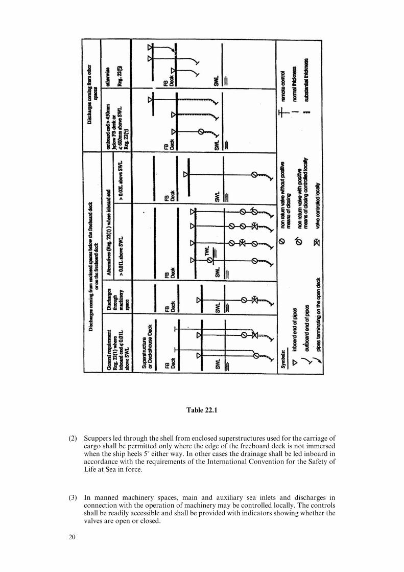
Table 22.1
(2) Scuppers led through the shell from enclosed superstructures used for the carriage ofcargo shall be permitted only where the edge of the freeboard deck is not immersedwhen the ship heels 5) either way. In other cases the drainage shall be led inboard inaccordance with the requirements of the International Convention for the Safety ofLife at Sea in force.
(3) In manned machinery spaces, main and auxiliary sea inlets and discharges inconnection with the operation of machinery may be controlled locally. The controlsshall be readily accessible and shall be provided with indicators showing whether thevalves are open or closed.
20
(4) Scuppers and discharge pipes originating at any level and penetrating the shell eithermore than 450 mm below the freeboard deck or less than 600 mm above the SummerLoad Line shall be provided with a non-return valve at the shell. This valve, unlessrequired by paragraph (2), may be omitted if the piping is of substantial thickness (seeparagraph (7) below).
(5) Scuppers leading from superstructures or deckhouses not fitted with doors complyingwith the requirements of regulation 12 shall be led overboard.
(6) All shell fittings and the valves required by this regulation shall be of steel, bronze orother approved ductile material. Valves of ordinary cast iron or similar material arenot acceptable. All pipes to which this regulation refers shall be of steel or otherequivalent material to the satisfaction of the Administration.
(7) Scupper and discharge pipes
(a) For scupper and discharge pipes, where substantial thickness is not required:
(i) for pipes having an external diameter equal to or less than 155 mm, thethickness shall not be less than 4.5 mm;
(ii) for pipes having an external diameter equal to or more than 230 mm, thethickness shall not be less than 6 mm.
Intermediate sizes shall be determined by linear interpolation.
(b) For scupper and discharge pipes, where substantial thickness is required:
(i) for pipes having an external diameter equal to or less than 80 mm, thethickness shall not be less than 7 mm;
(ii) for pipes having an external diameter of 180 mm, the thickness shall not beless than 10 mm;
(iii) for pipes having an external diameter equal to or more than 220 mm, thethickness shall not be less than 12.5 mm.
Intermediate sizes shall be determined by linear interpolation.
Regulation 22-1
Garbage chutes
(1) Two gate valves controlled from the working deck of the chute instead of the non-return valve with a positive means of closing from a position above the freeboard deckwhich comply with the following requirements are acceptable:
(a) the lower gate valve shall be controlled from a position above the freeboard deck.An interlock system between the two valves shall be arranged;
(b) the inboard end shall be located above the waterline formed by an 8.5) heel to portor starboard at a draft corresponding to the assigned summer freeboard, but notless than 1,000 mm above the summer waterline. Where the inboard end exceeds0.01L above the summer waterline, valve control from the freeboard deck is notrequired, provided the inboard gate valve is always accessible under serviceconditions; and
(c) alternatively, the upper and lower gate valves may be replaced by a hingedweathertight cover at the inboard end of the chute together with a discharge flap.The cover and flap shall be arranged with an interlock so that the discharge flapcannot be operated until the hopper cover is closed.
21

(2) The entire chute, including the cover, shall be contructed of material of substantialthickness.
(3) The controls for the gate valves and/or hinged covers shall be clearly marked: “Keepclosed when not in use”.
(4) Where the inboard end of the chute is below the freeboard deck of a passenger shipor the equilibrium waterlines of a cargo ship to which damage stability requirementsapply, then:
(a) the inboard and hinged cover/valve shall be watertight;
(b) the valve shall be a screw-down non-return valve fitted in an easily accessibleposition above the deepest load line; and
(c) the screw-down non-return valve shall be controlled from a position above thebulkhead deck and provided with open/closed indicators. The valve control shallbe clearly marked: “Keep closed when not in use”.
Regulation 22-2
Spurling pipes and cable lockers
(1) Spurling pipes and cable lockers shall be watertight up to the deck exposed to weather.
(2) Where means of access are provided, they shall be closed by a substantial cover andsecured by closely spaced bolts.
(3) Spurling pipes through which anchor cables are led shall be provided withpermanently attached closing appliances to minimize water ingress.
Regulation 23
Side scuttles, windows and skylights
(1) Side scuttles and windows, together with their glasses, deadlights and storm covers,1
if fitted, shall be of an approved design and substantial construction. Non-metallicframes are not acceptable.
(2) Side scuttles are defined as being round or oval openings with an area not exceeding0.16 m2. Round or oval openings having areas exceeding 0.6 m2 shall be treated aswindows.
(3) Windows are defined as being rectangular openings generally, having a radius at eachcorner relative to the window size and round or oval openings with an area exceeding0.16 m2.
(4) Side scuttles to the following spaces shall be fitted with hinged inside deadlights:
(a) spaces below freeboard deck;
(b) spaces within the first tier of enclosed superstructures; and
(c) first tier deckhouses on the freeboard deck protecting openings leading below orconsidered buoyant in stability calculations.
Deadlights shall be capable of being closed and secured watertight if fitted below thefreeboard deck and weathertight if fitted above.
(5) Side scuttles shall not be fitted in such a position that their sills are below a line drawnparallel to the freeboard deck at side and having its lowest point 2.5% of the breadth(B), or 500 mm, whichever is the greatest distance, above the Summer Load Line (orTimber Summer Load Line if assigned).
1Deadlights are fitted to the inside of windows and side scuttles, while storm covers are fitted to the outside of windows,where accessible, and may be hinged or portable.
22
(6) If the required damage stability calculations indicate that the side scuttles wouldbecome immersed at any intermediate stage of flooding or the final equilibriumwaterline, they shall be of the non-opening type.
(7) Windows shall not be fitted in the following locations:
(a) below the freeboard deck;
(b) in the first tier end bulkheads or sides of enclosed superstructures; or
(c) in the first tier deckhouses that are considered buoyant in the stability calculations.
(8) Side scuttles and windows at the side shell in the second tier shall be provided withhinged inside deadlights capable of being closed and secured weathertight if thesuperstructure protects direct access to an opening leading below or is consideredbuoyant in the stability calculations.
(9) Side scuttles and windows in side bulkheads set inboard from the side shell in thesecond tier which protect direct access below to spaces listed in paragraph (4) shall beprovided with either hinged inside deadlights or, where they are accessible,permanently attached external storm covers which are capable of being closed andsecured weathertight.
(10) Cabin bulkheads and doors in the second tier and above separating side scuttles andwindows from a direct access leading below or the second tier considered buoyant inthe stability calculations may be accepted in place of deadlights or storm covers fittedto the side scuttles and windows.
(11) Deckhouses situated on a raised quarter deck or on the deck of a superstructure ofless than standard height may be regarded as being in the second tier as far as therequirements for deadlights are concerned, provided that the height of the raisedquarter deck or superstructure is equal to or greater than the standard quarter deckheight.
(12) Fixed or opening skylights shall have a glass thickness appropriate to their size andposition as required for side scuttles and windows. Skylight glasses in any positionshall be protected from mechanical damage and, where fitted in position 1 or 2, shallbe provided with permanently attached deadlights or storm covers.
Regulation 24
Freeing ports
(1) (a) Where bulwarks on the weather portions of freeboard or superstructure decksform wells, ample provision shall be made for rapidly freeing the decks of waterand for draining them.
(b) Except as provided in paragraphs (1)(c) and (2), the minimum freeing port area(A) on each side of the ship for each well on the freeboard deck shall be that givenby the following formulae in cases where the sheer in way of the well is standardor greater than standard.
The minimum area for each well on superstructure decks shall be one-half of thearea given by the following formulae:
Where the length of bulwark (l) in the well is 20 m or less:
A % 0.7 ! 0.035 l(m2);
where l exceeds 20 m:
A % 0.07 l(m2).
l need in no case be taken as greater than 0.7L.
23
If the bulwark is more than 1.2 m in average height, the required area shall beincreased by 0.004 m2 per metre of length of well for each 0.1 m diVerence inheight. If the bulwark is less than 0.9 m in average height, the required area maybe decreased by 0.004 m2 per metre of length of well for each 0.1 m diVerence inheight.
(c) In ships with no sheer, the area calculated according to paragraph (b) shall beincreased by 50%. Where the sheer in less than the standard, the percentage shallbe obtained by linear interpolation.
(d) On a flush deck ship with a deckhouse amidships having a breadth of at least 80%of the beam of the ship and the passageways along the side of the ship not exceeding1.5 m in width, two wells are formed. Each shall be given the required freeing portarea based upon the length of each well.
(e) Where a screen bulkhead is fitted completely across the ship at the forward end ofa midship deckhouse, the exposed deck is divided into two wells and there is nolimitation on the breadth of the deckhouse.
(f) Wells on raised quarterdecks shall be treated as being on freeboard decks.
(g) Gutter bars greater than 300 mm in height fitted around the weather decks oftankers in way of cargo manifolds and cargo piping shall be treated as bulwarks.Freeing ports shall be arranged in accordance with this regulation. Closuresattached to the freeing ports for use during loading and discharge operations areto be arranged in such a way jamming cannot occur while at sea.
(2) Where a ship fitted with a trunk does not comply with the requirements of regulation36(1)(e) or where continuous or substantially continuous hatchway side coamings arefitted between detached superstructures, the minimum area of the freeing portopenings shall be calculated from the following table:
Breadth of hatchway or trunk in Area of freeing ports in relation torelation to the breadth of ship the total area of the bulwarks
40% or less 20%75% or more 10%
The area of freeing ports at intermediate breadths shall be obtained by linearinterpolation.
(3) The eVectiveness of the freeing area in bulwarks required by paragraph (1) dependson the free flow area across the deck of a ship.
The free flow area on deck is the net area of gaps between hatchways, and betweenhatchways and superstructures and deckhouses up to the actual height of thebulwark.
The freeing port area in bulwarks shall be assessed in relation to the net free flow areaas follows:
(a) If the free flow area is not less than the freeing area calculated from paragraph (2)as if the hatchway coamings were continuous, then the minimum freeing port areacalculated from paragraph (1) shall be deemed suYcient.
(b) If the free flow area is equal to, or less than the area calculated from paragraph (1),the minimum freeing area in the bulwarks shall be determined from paragraph (2).
(c) If the free flow area is smaller than calculated from paragraph (2), but greater thancalculated from paragraph (1), the minimum freeing area in the bulwark shall bedetermined from the following formula:
F % F1 ! F2 " fp (m2)
Where:
F1 is the minimum freeing area calculated from paragraph (1);
F2 is the minimum freeing area calculated from paragraph (2); and
24
fp is the total net area of passages and gaps between hatch ends andsuperstructures or deckhouses up to the actual height of bulwark.
(4) In ships having superstructures on the freeboard deck or superstructure decks, whichare open at either or both ends to wells formed by bulwarks on the open decks,adequate provision for freeing the open spaces within the superstructures shall beprovided.
The minimum freeing port area on each side of the ship for the open superstructure(As) and for the open well (Aw) shall be calculated in accordance with the followingprocedure:
(a) Determine the total well length (lt) equal to the sum of the length of the open deckenclosed by bulwarks (lw) and the length of the common space within the opensuperstructure (ls).
(b) To determine As:
(i) calculate the freeing port area (A) required for an open well of length lt inaccordance with paragraph (1) with standard height bulwark assumed;
(ii) multiply by a factor of 1.5 to correct for the absence of sheer, if applicable, inaccordance with paragraph (1)(c);
(iii) multiply by the factor (bo/lt) to adjust the freeing port area for the breadth (bo)of the openings in the end bulkhead of the enclosed superstructure;
(iv) to adjust the freeing port area for that part of the entire length of the wellwhich is enclosed by the open superstructure, multiply by the factor:
1 " (lw/lt)2
where lw and lt are defined in paragraph (4)(a);
(v) to adjust the freeing port area for the distance of the well deck above thefreeboard deck, for decks located more than 0.5 hs above the freeboard deck,multiply by the factor:
0.5 (hs/hw)
where hw is the distance of the well deck above the freeboard deck and hs isone standard superstructure height.
(c) to determine Aw:
(i) the freeing port area for the open well (Aw) shall be calculated in accordancewith paragraph (b)(i), using lw to calculate a nominal freeing port area (A'),and then adjusted for the actual height of the bulwark (hb) by the applicationof one of the following area corrections, whichever is applicable:
for bulwarks greater than 1.2 m in height:
Ac % lw((hb " 1.2)/0.10)(0.004) (m2);
for bulwarks less than 0.9 m in height:
Ac % lw((hb "0.9)/0.10)(0.004) (m2);
for bulwarks between 1.2 m and 0.9 m in height there is no correction(i.e. Ac % 0);
(ii) the corrected freeing port area (Aw % A' ! Ac) shall then be adjusted forabsence of sheer, if applicable, and height above freeboard deck as inparagraphs (b)(iii) and (b)(v), using hs and hw.
(d) The resulting freeing port areas for the open superstructure (As) and for the openwell (Aw) shall be provided along each side of the open space covered by the opensuperstructure and each side of the open well, respectively.
(e) The above relationships are summarised by the following equations, assuming lt,the sum of lw and ls, is greater than 20 m:
freeing port area Aw for the open well:
Aw % (0.07lw ! Ac) (sheer correction) (0.5hs/hw);
25
freeing port area As for the open superstructure:
As % (0.07lt) (sheer correction) (bo/lt) (l " (lw/lt)2) (0.5hs/hw);
where lt is 20 m or less, the basic freeing port area is A % 0.7 ! 0.035lt inaccordance with paragraph (1).
(5) The lower edges of freeing ports shall be as near the deck as practicable. Two-thirdsof the freeing port area required shall be provided in the half of the well nearest thelowest point of the sheer curve. One third of the freeing port area required shall beevenly spread along the remaining length of the well. With zero or little sheer on theexposed freeboard deck or an exposed superstructure deck the freeing port area shallbe evenly spread along the length of the well.
(6) All freeing port openings in the bulwarks shall be protected by rails or bars spacedapproximately 230 mm apart. If shutters are fitted to freeing ports, ample clearanceshall be provided to prevent jamming. Hinges shall have pins or bearings of non-corrodible material. Shutters shall not be fitted with securing appliances.
Regulation 25
Protection of the crew
(1) The deckhouses used for the accommodation of the crew shall be constructed to anacceptable level of strength.
(2) Guard rails or bulwarks shall be fitted around all exposed decks. The height of thebulwarks or guard rails shall be at least 1 m from the deck, provided that where thisheight would interfere with the normal operation of the ship, a lesser height may beapproved, if the Administration is satisfied that adequate protection is provided.
(3) Guard rails fitted on superstructure and freeboard decks shall have at least threecourse. The opening below the lowest course of the guard rails shall not exceed 230mm. The other courses shall be not more than 380 mm apart. In the case of ships withrounded gunwales the guard rail supports shall be placed on the flat of the deck. Inother locations, guardrails with at least two courses shall be fitted. Guard rails shallcomply with the following provisions:
(a) fixed, removable or hinged stanchions shall be fitted about 1.5 m apart. Removableor hinged stanchions shall be capable of being locked in the upright position;
(b) at least every third stanchion shall be supported by a bracket or stay;
(c) where necessary for the normal operation of the ship, steel wire ropes may beaccepted in lieu of guard rails. Wires shall be made taut by means of turnbuckles;and
(d) where necessary for the normal operation of the ship, chains fitted between twofixed stanchions and/or bulwarks are acceptable in lieu of guard rails.
(4) Satisfactory means for safe passage required by regulation 25-1 (in the form of guardrails, lifelines, gangways or underdeck passages, etc.) shall be provided for theprotection of the crew in getting to and from their quarters, the machinery space andany other spaces used in the essential operation of the ship.
(5) Deck cargo carried on any ship shall be so stowed that any opening which is in wayof the cargo and which gives access to and from the crew’s quarters, the machineryspace and all other parts used in the essential operation of the ship can be closed andsecured against water ingress. Protection for the crew in the form of guard rails orlifelines shall be provided above the deck cargo if there is no convenient passage onor below the deck of the ship.
26
Regulation 25-1
Means for safe passage of crew
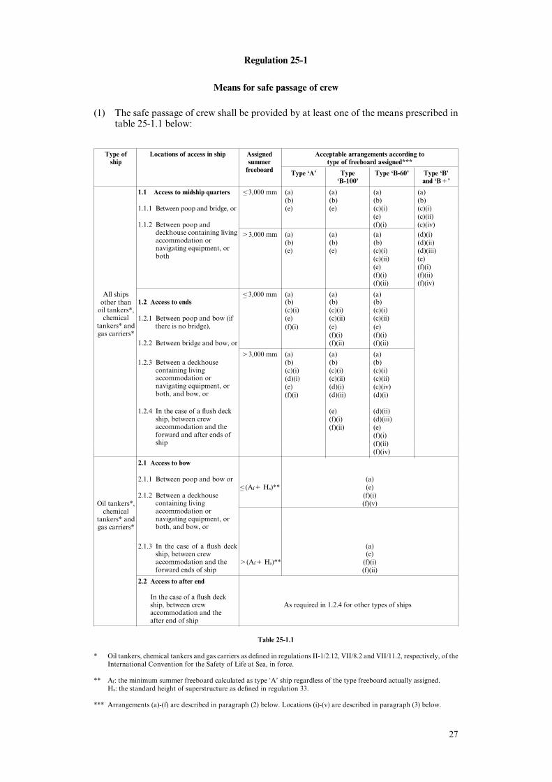
(1) The safe passage of crew shall be provided by at least one of the means prescribed intable 25-1.1 below:
Type of Locations of access in ship Assigned Acceptable arrangements according toship summer type of freeboard assigned***
freeboard Type ‘A’ Type Type ‘B-60’ Type ‘B’‘B-100’ and ‘B!’
1.1 Access to midship quarters '– 3,000 mm (a) (a) (a) (a)(b) (b) (b) (b)
1.1.1 Between poop and bridge, or (e) (e) (c)(i) (c)(i)(e) (c)(ii)
1.1.2 Between poop and (f)(i) (c)(iv)deckhouse containing livingaccommodation ornavigating equipment, orboth
(3,000 mm (a) (a) (a) (d)(i)(b) (b) (b) (d)(ii)(e) (e) (c)(i) (d)(iii)
(c)(ii) (e)(e) (f)(i)(f)(i) (f)(ii)(f)(ii) (f)(iv)
All ships '– 3,000 mm (a) (a) (a)other than
oil tankers*,chemical
tankers* andgas carriers*
1.2 Access to ends (b) (b) (b)(c)(i) (c)(i) (c)(i)
1.2.1 Between poop and bow (if (e) (c)(ii) (c)(ii)there is no bridge), (f)(i) (e) (e)
(f)(i) (f)(i)1.2.2 Between bridge and bow, or (f)(ii) (f)(ii)
(3,000 mm (a) (a) (a)1.2.3 Between a deckhouse (b) (b) (b)
containing livingaccommodation ornavigating equipment, orboth, and bow, or
(c)(i) (c)(i) (c)(i)(d)(i) (c)(ii) (c)(ii)(e) (d)(i) (c)(iv)(f)(i) (d)(ii) (d)(i)
1.2.4 In the case of a flush deck (e) (d)(ii)ship, between crewaccommodation and theforward and after ends ofship
(f)(i) (d)(iii)(f)(ii) (e)
(f)(i)(f)(ii)(f)(iv)
2.1 Access to bow
2.1.1 Between poop and bow or (a)'– (Af! Hs)** (e)
2.1.2 Between a deckhouse (f)(i)containing livingaccommodation ornavigating equipment, orboth, and bow, or
Oil tankers*, (f)(v)chemical
tankers* andgas carriers*
2.1.3 In the case of a flush deck (a)ship, between crewaccommodation and theforward ends of ship
(e)((Af! Hs)** (f)(i)
(f)(ii)
2.2 Access to after end
In the case of a flush deckship, between crew As required in 1.2.4 for other types of shipsaccommodation and theafter end of ship
Table 25-1.1
* Oil tankers, chemical tankers and gas carriers as defined in regulations II-1/2.12, VII/8.2 and VII/11.2, respectively, of theInternational Convention for the Safety of Life at Sea, in force.
** Af: the minimum summer freeboard calculated as type ‘A’ ship regardless of the type freeboard actually assigned.Hs: the standard height of superstructure as defined in regulation 33.
*** Arrangements (a)-(f) are described in paragraph (2) below. Locations (i)-(v) are described in paragraph (3) below.
27

(2) Acceptable arrangements referred to in table 25-1.1 are defined as follows:
(a) A well lighted and ventilated under-deck passageway (with a clear opening of atleast 0.8 m wide and 2 m high), as close as practicable to the freeboard deck,connecting and providing access to the locations in question.
(b) A permanent and eYciently constructed gangway, fitted at or above the level ofthe superstructure deck, on or as near as practicable to the centre line of the ship,providing a continuous platform at least 0.6 m in width and a non-slip surface andwith guard rails extending on each side throughout its length. Guard rails shall beat least 1 m high with three courses and constructed as required in regulation 25(3).A foot-stop shall be provided.
(c) A permanent walkway at least 0.6 m in width, fitted at freeboard deck level andconsisting of two rows of guard rails with stanchions spaced not more than 3 m.The number of courses of rails and their spacing shall be in accordance withregulation 25(3). On type ‘B’ ships, hatchway coamings not less than 0.6 m inheight may be accepted as forming one side of the walkway, provided that tworows of guard rails are fitted between the hatchways.
(d) A wire rope lifeline not less than 10 mm in diameter, supported by stanchions notmore than 10 m apart, or a single hand rail or wire rope attached to hatchcoamings, continued and supported between hatchways.
(e) A permanent gangway that is:
(i) located at or above the level of the superstructure deck;
(ii) located on or as near as practicable to the centre line of the ship;
(iii) located so as not to hinder easy access across the working areas of the deck;
(iv) providing a continuous platform at least 1 m in width;
(v) constructed of fire resistant and non-slip material;
(vi) fitted with guard rails extending on each side throughout its length; guard railsshall be at least 1 m high with courses as required by regulation 25(3) andsupported by stanchions spaced not more than 1.5 m apart;
(vii) provided with a foot-stop on each side;
(viii)having openings, with ladders where appropriate, to and from the deck.Openings shall not be more than 40 m apart; and
(ix) having shelters set in way of the gangway at intervals not exceeding 45 m ifthe length of the exposed deck to be traversed exceeds 70 m. Every such sheltershall be capable of accommodating at least one person and be so constructedas to aVord weather protection on the forward, port and starboard sides.
(f) A permanent walkway located at the freeboard deck level, on or as near aspracticable to the centre line of the ship, having the same specifications as those fora permanent gangway listed in (e), except for foot-stops. On type ‘B’ ships (certifiedfor the carriage of liquids in bulk) with a combined height of hatch coaming andfitted hatch cover of not less than 1 m in height, the hatchway coamings may beaccepted as forming one side of the walkway, provided that two rows of guard railsare fitted between the hatchways.
(3) Permitted transverse locations for arrangements in paragraphs (2)(c), (d) and (f)above, where appropriate:
(i) at or near the centre line of the ship; or fitted on hatchways at or near the centreline of the ship;
(ii) fitted on each side of the ship;
(iii) fitted on one side of the ship, provision being made for fitting on either side;
(iv) fitted on one side of the ship only;
(v) fitted on each side of the hatchways, as near to the centre line as practicable.
28
(4) (a) Where wire ropes are fitted, turnbuckles shall be provided to ensure theirtautness.
(b) Where necessary for the normal operation of the ship, steel wire ropes may beaccepted in lieu of guard rails.
(c) Where necessary for the normal operation of the ship, chains fitted between twofixed stanchions are acceptable in lieu of guard rails.
(d) Where stanchions are fitted, every third stanchion shall be supported by a bracketor stay.
(e) Removable or hinged stanchions shall be capable of being locked in the uprightposition.
(f) A means of passage over obstructions such as pipes or other fittings of apermanent nature, shall be provided.
(g) Generally, the width of the gangway or deck-level walkway should not exceed1.5 m.
(5) For tankers less than 100 m in length, the minimum width of the gangway platformor deck-level walkway fitted in accordance with paragraphs (2)(e) or (f) above,respectively, may be reduced to 0.6 m.
Regulation 26
Special conditions of assignment for type ‘A’ ships
Machinery casings
(1) Machinery casings on type ‘A’ ships, as defined in regulation 27, shall be protected byone of the following arrangements:
(a) an enclosed poop or bridge of at least standard height; or
(b) a deckhouse of equal height and equivalent strength.
(2) Machinery casings may, however, be exposed if there are no openings giving directaccess from the freeboard deck to the machinery space. A door complying with therequirements of regulation 12 is acceptable in the machinery casing, provided that itleads to a space or passageway which is as strongly constructed as the casing and isseparated from the stairway to the engine-room by a second weathertight door of steelor other equivalent material.
Gangway and access
(3) A fore and aft permanent gangway, constructed in accordance with the provisions ofregulation 25-1(2)(e), shall be fitted on type ‘A’ ships at the level of the superstructuredeck between the poop and the midship bridge or deckhouse where fitted. Thearrangement contained in regulation 25-1(2)(a) is considered an equivalent means ofaccess to carry out the purpose of the gangway.
29

(4) Safe access from the gangway level shall be available between separate crewaccommodations and also between crew accommodations and the machinery space.
Hatchways
(5) Exposed hatchways on the freeboard and forecastle decks or on the tops of expansiontrunks on type ‘A’ ships shall be provided with eYcient watertight covers of steel orother equivalent material.
Freeing arrangements
(6) Type ‘A’ ships with bulwarks shall have open rails fitted for at least half the length ofthe weather deck or other equivalent freeing arrangements. A freeing port area, in thelower part of the bulwarks, of 33% of the total area of the bulwarks, is an acceptableequivalent freeing arrangement. The upper edge of the sheer strake shall be kept aslow as practicable.
(7) Where superstructures are connected by trunks, open rails shall be fitted for the wholelength of the exposed parts of the freeboard deck.
Chapter III
Freeboards
Regulation 27
Types of ships
(1) For the purposes of freeboard computation, ships shall be divided into type ‘A’ andtype ‘B’.
Type ‘A’ ships
(2) A type ‘A’ ship is a ship which:
(a) is designed to carry only liquid cargoes in bulk;
(b) has a high integrity of the exposed deck with only small access openings to cargocompartments, closed by watertight gasketed covers of steel or equivalentmaterial; and
(c) has low permeability of loaded cargo compartments.
(3) A type ‘A’ ship, if over 150 m in length, to which a freeboard less than type ‘B’ hasbeen assigned, when loaded in accordance with the requirements of paragraph (11),shall be able to withstand the flooding of any compartment or compartments, withan assumed permeability of 0.95, consequent upon the damage assumptions specifiedin paragraph (12), and shall remain afloat in a satisfactory condition of equilibrium,as specified in paragraph (13). In such a ship, the machinery space shall be treated asa floodable compartment, but with a permeability of 0.85.
(4) A type ‘A’ ship shall be assigned a freeboard not less than that given in table 28.1.
Type ‘B’ ships
(5) All ships which do not come within the provisions regarding type ‘A’ ships inparagraphs (2) and (3) shall be considered as type ‘B’ ships.
(6) Type ‘B’ ships, which in position 1 have hatch covers which are permitted by theAdministration to comply with the requirements of regulation 15 (other thanparagraph (6)) or which are fitted with securing arrangements accepted under theprovisions of regulation 16(6), shall be assigned freeboards based upon the valuesgiven in table 28.2, increased by the values given in table 27.1:
30

Freeboard increase over tabular freeboard for type ‘B’ ships, for ships with hatch coverscomplying with the provisions of regulation 15 (other than paragraph (6))
Length Freeboard Length Freeboard Length Freeboardof ship increase of ship increase of ship increase
(m) (mm) (m) (mm) (m) (mm)
108 and below 50 139 175 170 290109 52 140 181 171 292110 55 141 186 172 294111 57 142 191 173 297112 59 143 196 174 299113 62 144 201 175 301114 64 145 206 176 304115 68 146 210 177 306116 70 147 215 178 308117 73 148 219 179 311118 76 149 224 180 313119 80 150 228 181 315120 84 151 232 182 318121 87 152 236 183 320122 91 153 240 184 322123 95 154 244 185 325124 99 155 247 186 327125 103 156 251 187 329126 108 157 254 188 332127 112 158 258 189 334128 116 159 261 190 336129 121 160 264 191 339130 126 161 267 192 341131 131 162 270 193 343132 136 163 273 194 346133 142 164 275 195 348134 147 165 278 196 350135 153 166 280 197 353136 159 167 283 198 355137 164 168 285 199 357138 170 169 287 200 358
Freeboards at intermediate lengths of ship shall be obtained by linear interpolation. Shipsabove 200 m in length shall be dealt with by the Administration.
Table 27.1(7) Type ‘B’ ships, which in position 1 have hatchways fitted with hatch covers complying
with the requirements of regulation 16(2) through (5), shall, except as provided inparagraphs (8) to (13) inclusive, be assigned freeboards based on table 28.2.
(8) Any type ‘B’ ship of over 100 m in length may be assigned freeboards less than thoserequired under paragraph (7), provided that, in relation to the amount of reductiongranted, the Administration is satisfied that:
the measures provided for the protection of the crew are adequate;(a)
the freeing arrangements are adequate;(b)
the covers in position 1 and 2 comply with the provisions of regulation 16(1)(c)through (5) and (7); and
the ship, when loaded in accordance with the requirements of paragraph (11), shall(d)be able to withstand the flooding of any compartment or compartments, with anassumed permeability of 0.95, consequent upon the damage assumptions specifiedin paragraph (12), and shall remain afloat in a satisfactory condition ofequilibrium, as specified in paragraph (13). In such a ship, if over 150 m in length,the machinery space shall be treated as a floodable compartment, but with apermeability of 0.85.
31

(9) In calculating the freeboards for type ‘B’ ships which comply with the requirementsof paragraphs (8), (11), (12) and (13), the values from table 28.2 shall not be reducedby more than 60% of the diVerence between the tabular values in tables 28.1 and 28.2for the appropriate ship lengths.
(10) (a) The reduction in tabular freeboard allowed under paragraph (9) may be increasedup to the total diVerence between the values in table 28.1 and those in table 28.2on condition that the ship complies with the requirements of:
(i) regulation 26, other than paragraph (5), as if it were a type ‘A’ ship;
(ii) paragraphs (8), (11) and (13); and
(iii) paragraph (12), provided that throughout the length of the ship any onetransverse bulkhead will be assumed to be damaged, such that two adjacentfore and aft compartments shall be flooded simultaneously, except that suchdamage will not apply to the boundary bulkheads of a machinery space.
(b) In such a ship, if over 150 m in length, the machinery space shall be treated as afloodable compartment, but with a permeability of 0.85.
Initial condition of loading
(11) The initial condition of loading before flooding shall be determined as follows:
(a) The ship is loaded to its Summer Load Waterline on an imaginary even keel.
(b) When calculating the vertical centre of gravity, the following principles apply:
(i) homogeneous cargo is carried;
(ii) all cargo compartments, except those referred to under subparagraph (iii), butincluding compartments intended to be partially filled, shall be consideredfully loaded except that in the case of fluid cargoes each compartment shall betreated as 98% full;
(iii) if the ship is intended to operate at its Summer Load Waterline with emptycompartments, such compartments shall be considered empty, provided theheight of the centre of gravity so calculated is not less than as calculated undersubparagraph (ii);
(iv) 50% of the individual total capacity of all tanks and spaces fitted to containconsumable liquids and stores is allowed for. It shall be assumed that for eachtype of liquid at least one transverse pair or a single centreline tank hasmaximum free surface, and the tank or combination of tanks to be taken intoaccount shall be those where the eVect of free surfaces is the greatest; in eachtank the centre of gravity of the contents shall be taken at the centre of volumeof the tank. The remaining tanks shall be assumed either completely emptyor completely filled, and the distribution of consumable liquids between thesetanks shall be eVected so as to obtain the greatest possible height above thekeel for the centre of gravity;
(v) at an angle of heel of not more than 5) in each compartment containingliquids, as prescribed in subparagraph (ii), except that in the case ofcompartments containing consumable fluids, as prescribed in subparagraph(iv), the maximum free surface eVect shall be taken into account.Alternatively, the actual free surface eVects may be used, provided themethods of calculation are acceptable to the Administration;
32
(vi) weights shall be calculated on the basis of the following values for specificgravities:
salt water 1.025
fresh water 1.000
oil fuel 0.950
diesel oil 0.900
lubricating oil 0.900.
Damage assumptions
(12) The following principles regarding the character of the assumed damage apply:
(a) The vertical extent of damage in all cases is assumed to be from the base lineupwards without limit.
(b) The transverse extent of damage is equal to B/5 or 11.5 m, whichever is the lesser,measured inboard from the side of the ship perpendicularly to the centreline at thelevel of the summer load waterline.
(c) If damage of a lesser extent than specified in subparagraphs (a) and (b) results ina more severe condition, such lesser extent shall be assumed.
(d) Except where otherwise required by paragraph (10)(a), the flooding shall beconfined to a single compartment between adjacent transverse bulkheads,provided that the inner longitudinal boundary of the compartment is not in aposition within the transverse extent of assumed damage. Transverse boundarybulkheads of wing tanks which do not extend over the full breadth of the ship shallbe assumed not to be damaged, provided that they extend beyond the transverseextent of assumed damage prescribed in subparagraph (b).
If in a transverse bulkhead there are steps or recesses of not more than 3 m inlength, located within the transverse extent of assumed damage as defined insubparagraph (b), such transverse bulkhead may be considered intact and theadjacent compartment may be floodable singly. If, however, within the transverseextent of assumed damage there is a step or recess of more than 3 m in length ina transverse bulkhead, the two compartments adjacent to this bulkhead shall beconsidered as flooded. The step formed by the afterpeak bulkhead and theafterpeak tank top shall not be regarded as a step for the purpose of this regulation.
(e) Where a main transverse bulkhead is located within the transverse extent ofassumed damage and is stepped in way of a double bottom or side tank by morethan 3 m, the double bottom or side tanks adjacent to the stepped portion of themain transverse bulkhead shall be considered as flooded simultaneously. If thisside tank has openings into one or several holds, such as grain feeding holes, suchhold or holds shall be considered as flooded simultaneously. Similarly, in a shipdesigned for the carriage of fluid cargoes, if a side tank has openings into adjacentcompartments, such adjacent compartments shall be considered as empty and asbeing flooded simultaneously. This provision is applicable even where suchopenings are fitted with closing appliances, except in the case of sluice valves fittedin bulkheads between tanks and where the valves are controlled from the deck.Manhole covers with closely spaced bolts are considered equivalent to theunpierced bulkhead, except in the case of openings in topside tanks making thetopside tanks common to the holds.
(f) Where the flooding of any two adjacent fore and aft compartments is envisaged,main transverse watertight bulkheads shall be spaced at least 1/3 L2/3 or 14.5 m,whichever is the lesser, in order to be considered eVective. Where transversebulkheads are spaced at a lesser distance, one or more of these bulkheads shall beassumed as non-existent in order to achieve the minimum spacing betweenbulkheads.
33

Condition of equilibrium
(13) The condition of equilibrium after flooding shall be regarded as satisfactoryprovided:
(a) The final waterline after flooding, taking into account sinkage, heel and trim, isbelow the lower edge of any opening through which progressive downflooding maytake place. Such openings shall include air pipes, ventilators (even if they complywith regulation 19(4)) and openings which are closed by means of weathertightdoors (even if they comply with regulation 12) or hatch covers (even if they complywith regulation 16(1) through (5)), and may exclude those openings closed bymeans of manhole covers and flush scuttles (which comply with regulation 18),cargo hatch covers of the type described in regulation 27(2), remotely operatedsliding watertight doors, and sidescuttles of the non-opening type (which complywith regulation 23). However, in the case of doors separating a main machineryspace from a steering gear compartment, watertight doors may be of a hinged,quick-acting type kept closed at sea whilst not in use, provided also that the lowersill of such doors is above the summer load waterline.
(b) If pipes, ducts or tunnels are situated within the assumed extent of damagepenetration as defined in paragraph (12)(b), arrangements shall be made so thatprogressive flooding cannot thereby extend to compartments other than thoseassumed to be floodable in the calculation for each case of damage.
(c) The angle of heel due to unsymmetrical flooding does not exceed 15). If no part ofthe deck is immersed, an angle of heel of up to 17) may be accepted.
(d) The metacentric height in the flooded condition is positive.
(e) When any part of the deck outside the compartment assumed flooded in aparticular case of damage is immersed, or in any case where the margin of stabilityin the flooded condition may be considered doubtful, the residual stability is to beinvestigated. It may be regarded as suYcient if the righting lever curve has aminimum range of 20) beyond the position of equilibrium with a maximumrighting lever of at least 0.1 m within this range. The area under the righting levercurve within this range shall be not less than 0.0175 m.rad. The Administrationshall give consideration to the potential hazard presented by protected orunprotected openings which may become temporarily immersed within the rangeof residual stability.
(f) The Administration is satisfied that the stability is suYcient during intermediatestages of flooding.
Ships without means of propulsion
(14) A lighter, barge or other ship without independent means of propulsion shall beassigned a freeboard in accordance with the provisions of these regulations. Bargeswhich meet the requirements of paragraphs (2) and (3) may be assigned type ‘A’freeboards:
(a) The Administration should especially consider the stability of barges with cargoon the weather deck. Deck cargo can only be carried on barges to which theordinary type ‘B’ freeboard is assigned.
(b) However, in the case of barges which are unmanned, the requirements ofregulations 25, 26(3), 26(4) and 39 shall not apply.
(c) Such unmanned barges which have on the freeboard deck only small accessopenings closed by watertight gasketed covers of steel or equivalent material maybe assigned a freeboard 25% less than those calculated in accordance with theseregulations.
34
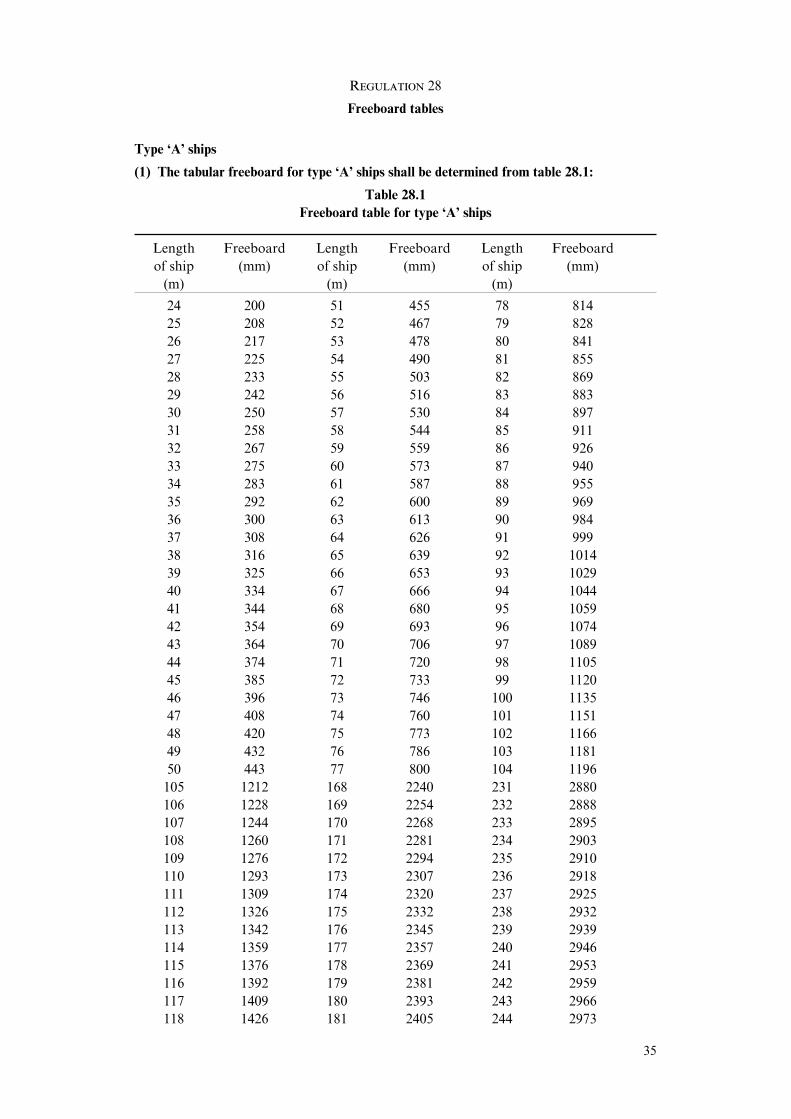
Regulation 28
Freeboard tables
Type ‘A’ ships
(1) The tabular freeboard for type ‘A’ ships shall be determined from table 28.1:
Table 28.1Freeboard table for type ‘A’ ships
Length Freeboard Length Freeboard Length Freeboard
of ship (mm) of ship (mm) of ship (mm)
(m) (m) (m)
24 200 51 455 78 814
25 208 52 467 79 828
26 217 53 478 80 841
27 225 54 490 81 855
28 233 55 503 82 869
29 242 56 516 83 883
30 250 57 530 84 897
31 258 58 544 85 911
32 267 59 559 86 926
33 275 60 573 87 940
34 283 61 587 88 955
35 292 62 600 89 969
36 300 63 613 90 984
37 308 64 626 91 999
38 316 65 639 92 1014
39 325 66 653 93 1029
40 334 67 666 94 1044
41 344 68 680 95 1059
42 354 69 693 96 1074
43 364 70 706 97 1089
44 374 71 720 98 1105
45 385 72 733 99 1120
46 396 73 746 100 1135
47 408 74 760 101 1151
48 420 75 773 102 1166
49 432 76 786 103 1181
50 443 77 800 104 1196
105 1212 168 2240 231 2880
106 1228 169 2254 232 2888
107 1244 170 2268 233 2895
108 1260 171 2281 234 2903
109 1276 172 2294 235 2910
110 1293 173 2307 236 2918
111 1309 174 2320 237 2925
112 1326 175 2332 238 2932
113 1342 176 2345 239 2939
114 1359 177 2357 240 2946
115 1376 178 2369 241 2953
116 1392 179 2381 242 2959
117 1409 180 2393 243 2966
118 1426 181 2405 244 2973
35

Length Freeboard Length Freeboard Length Freeboard
of ship (mm) of ship (mm) of ship (mm)
(m) (m) (m)
119 1442 182 2416 245 2979
120 1459 183 2428 246 2986
121 1476 184 2440 247 2993
122 1494 185 2451 248 3000
123 1511 186 2463 249 3006
124 1528 187 2474 250 3012
125 1546 188 2486 251 3018
126 1563 189 2497 252 3024
127 1580 190 2508 253 3030
128 1598 191 2519 254 3036
129 1615 192 2530 255 3042
130 1632 193 2541 256 3048
131 1650 194 2552 257 3054
132 1667 195 2562 258 3060
133 1684 196 2572 259 3066
134 1702 197 2582 260 3072
135 1719 198 2592 261 3078
136 1736 199 2602 262 3084
137 1753 200 2612 263 3089
138 1770 201 2622 264 3095
139 1787 202 2632 265 3101
140 1803 203 2641 266 3106
141 1820 204 2650 267 3112
142 1837 205 2659 268 3117
143 1853 206 2669 269 3123
144 1870 207 2678 270 3128
145 1886 208 2687 271 3133
146 1903 209 2696 272 3138
147 1919 210 2705 273 3143
148 1935 211 2714 274 3148
149 1952 212 2723 275 3153
150 1968 213 2732 276 3158
151 1984 214 2741 277 3163
152 2000 215 2749 278 3167
153 2016 216 2758 279 3172
154 2032 217 2767 280 3176
155 2048 218 2775 281 3181
156 2064 219 2784 282 3185
157 2080 220 2792 283 3189
158 2096 221 2801 284 3194
159 2111 222 2809 285 3198
160 2126 223 2817 286 3202
161 2141 224 2825 287 3207
162 2155 225 2833 288 3211
163 2169 226 2841 289 3215
164 2184 227 2849 290 3220
165 2198 228 2857 291 3224
166 2212 229 2865 292 3228
167 2226 230 2872 293 3233
36
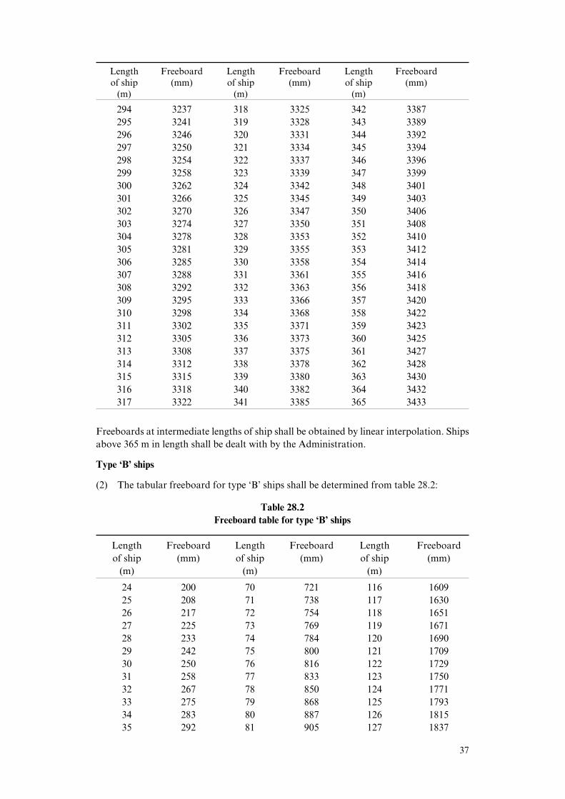
Length Freeboard Length Freeboard Length Freeboard
of ship (mm) of ship (mm) of ship (mm)
(m) (m) (m)
294 3237 318 3325 342 3387
295 3241 319 3328 343 3389
296 3246 320 3331 344 3392
297 3250 321 3334 345 3394
298 3254 322 3337 346 3396
299 3258 323 3339 347 3399
300 3262 324 3342 348 3401
301 3266 325 3345 349 3403
302 3270 326 3347 350 3406
303 3274 327 3350 351 3408
304 3278 328 3353 352 3410
305 3281 329 3355 353 3412
306 3285 330 3358 354 3414
307 3288 331 3361 355 3416
308 3292 332 3363 356 3418
309 3295 333 3366 357 3420
310 3298 334 3368 358 3422
311 3302 335 3371 359 3423
312 3305 336 3373 360 3425
313 3308 337 3375 361 3427
314 3312 338 3378 362 3428
315 3315 339 3380 363 3430
316 3318 340 3382 364 3432
317 3322 341 3385 365 3433
Freeboards at intermediate lengths of ship shall be obtained by linear interpolation. Ships
above 365 m in length shall be dealt with by the Administration.
Type ‘B’ ships
(2) The tabular freeboard for type ‘B’ ships shall be determined from table 28.2:
Table 28.2Freeboard table for type ‘B’ ships
Length Freeboard Length Freeboard Length Freeboard
of ship (mm) of ship (mm) of ship (mm)
(m) (m) (m)
24 200 70 721 116 1609
25 208 71 738 117 1630
26 217 72 754 118 1651
27 225 73 769 119 1671
28 233 74 784 120 1690
29 242 75 800 121 1709
30 250 76 816 122 1729
31 258 77 833 123 1750
32 267 78 850 124 1771
33 275 79 868 125 1793
34 283 80 887 126 1815
35 292 81 905 127 1837
37

Length Freeboard Length Freeboard Length Freeboard
of ship (mm) of ship (mm) of ship (mm)
(m) (m) (m)
36 300 82 923 128 1859
37 308 83 942 129 1880
38 316 84 960 130 1901
39 325 85 978 131 1921
40 334 86 996 132 1940
41 344 87 1015 133 1959
42 354 88 1034 134 1979
43 364 89 1054 135 2000
44 374 90 1075 136 2021
45 385 91 1096 137 2043
46 396 92 1116 138 2065
47 408 93 1135 139 2087
48 420 94 1154 140 2109
49 432 95 1172 141 2130
50 443 96 1190 142 2151
51 455 97 1209 143 2171
52 467 98 1229 144 2190
53 478 99 1250 145 2209
54 490 100 1271 146 2229
55 503 101 1293 147 2250
56 516 102 1315 148 2271
57 530 103 1337 149 2293
58 544 104 1359 150 2315
59 559 105 1380 151 2334
60 573 106 1401 152 2354
61 587 107 1421 153 2375
62 601 108 1440 154 2396
63 615 109 1459 155 2418
64 629 110 1479 156 2440
65 644 111 1500 157 2460
66 659 112 1521 158 2480
67 674 113 1543 159 2500
68 689 114 1565 160 2520
69 705 115 1587 161 2540
162 2560 225 3660 288 4490
163 2580 226 3675 289 4502
164 2600 227 3690 290 4513
165 2620 228 3705 291 4525
166 2640 229 3720 292 4537
167 2660 230 3735 293 4548
168 2680 231 3750 294 4560
169 2698 232 3765 295 4572
170 2716 233 3780 296 4583
171 2735 234 3795 297 4595
172 2754 235 3808 298 4607
173 2774 236 3821 299 4618
174 2795 237 3835 300 4630
175 2815 238 3849 301 4642
176 2835 239 3864 302 4654
38
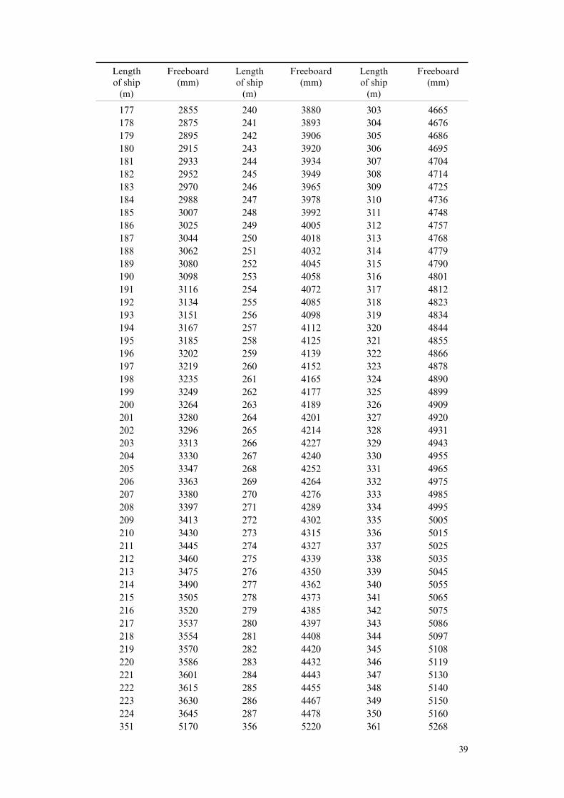
Length Freeboard Length Freeboard Length Freeboard
of ship (mm) of ship (mm) of ship (mm)
(m) (m) (m)
177 2855 240 3880 303 4665
178 2875 241 3893 304 4676
179 2895 242 3906 305 4686
180 2915 243 3920 306 4695
181 2933 244 3934 307 4704
182 2952 245 3949 308 4714
183 2970 246 3965 309 4725
184 2988 247 3978 310 4736
185 3007 248 3992 311 4748
186 3025 249 4005 312 4757
187 3044 250 4018 313 4768
188 3062 251 4032 314 4779
189 3080 252 4045 315 4790
190 3098 253 4058 316 4801
191 3116 254 4072 317 4812
192 3134 255 4085 318 4823
193 3151 256 4098 319 4834
194 3167 257 4112 320 4844
195 3185 258 4125 321 4855
196 3202 259 4139 322 4866
197 3219 260 4152 323 4878
198 3235 261 4165 324 4890
199 3249 262 4177 325 4899
200 3264 263 4189 326 4909
201 3280 264 4201 327 4920
202 3296 265 4214 328 4931
203 3313 266 4227 329 4943
204 3330 267 4240 330 4955
205 3347 268 4252 331 4965
206 3363 269 4264 332 4975
207 3380 270 4276 333 4985
208 3397 271 4289 334 4995
209 3413 272 4302 335 5005
210 3430 273 4315 336 5015
211 3445 274 4327 337 5025
212 3460 275 4339 338 5035
213 3475 276 4350 339 5045
214 3490 277 4362 340 5055
215 3505 278 4373 341 5065
216 3520 279 4385 342 5075
217 3537 280 4397 343 5086
218 3554 281 4408 344 5097
219 3570 282 4420 345 5108
220 3586 283 4432 346 5119
221 3601 284 4443 347 5130
222 3615 285 4455 348 5140
223 3630 286 4467 349 5150
224 3645 287 4478 350 5160
351 5170 356 5220 361 5268
39

Length Freeboard Length Freeboard Length Freeboard
of ship (mm) of ship (mm) of ship (mm)
(m) (m) (m)
352 5180 357 5230 362 5276
353 5190 358 5240 363 5285
354 5200 359 5250 364 5294
355 5210 360 5260 365 5303
Freeboards at intermediate lengths of ship shall be obtained by linear interpolation. Ships
above 365 m in length shall be dealt with by the Administration.
Regulation 29
Correction to the freeboard for ships under 100 m in length
The tabular freeboard for a type ‘B’ ship of between 24 m and 100 m in length havingenclosed superstructures with an eVective length of up to 35% of the length of the ship shallbe increased by:
` E1\
7.5 (100 – L) _ 0.35" _ (mm)Lb ^
where L is the length of the ship in m; and
E1 is the eVective length E of superstructure in m as defined in regulation 35, butexcluding the length of trunks.
Regulation 30
Correction for block coeYcient
Where the block coeYcient (Cb) exceeds 0.68, the tabular freeboard specified in regulation28 as modified, if applicable, by regulations 27(8), 27(10) and 29 shall be multiplied bythe factor:
Cb ! 0.68
1.36
The block coeYcient is not to be taken greater than 1.0.
Regulation 31
Correction for depth
(1) Where D exceedsL—15 the freeboard shall be increased by
`_b
D "L—
15\_^
R (mm), where
R isL—0.48 at lengths less than 120 m and 250 at 120 m length and above.
(2) Where D is less thanL—15 no reduction shall be made, except in a ship with an enclosed
superstructure covering at least 0.6L amidships, with a complete trunk, orcombination of detached enclosed superstructures and trunks which extend all foreand aft, where the freeboard shall be reduced at the rate prescribed in paragraph (1).
(3) Where the height of the superstructure or trunk is less than the correspondingstandard height, the calculated reduction shall be corrected in the ratio of the heightof the actual superstructure or trunk to the applicable standard height, as defined inregulation 33.
40
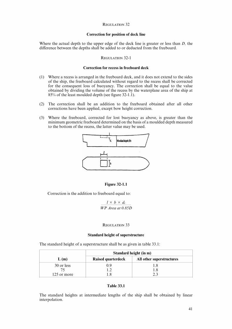
Regulation 32
Correction for position of deck line
Where the actual depth to the upper edge of the deck line is greater or less than D, thediVerence between the depths shall be added to or deducted from the freeboard.
Regulation 32-1
Correction for recess in freeboard deck
(1) Where a recess is arranged in the freeboard deck, and it does not extend to the sidesof the ship, the freeboard calculated without regard to the recess shall be correctedfor the consequent loss of buoyancy. The correction shall be equal to the valueobtained by dividing the volume of the recess by the waterplane area of the ship at85% of the least moulded depth (see figure 32-1.1).
(2) The correction shall be an addition to the freeboard obtained after all othercorrections have been applied, except bow height correction.
(3) Where the freeboard, corrected for lost buoyancy as above, is greater than theminimum geometric freeboard determined on the basis of a moulded depth measuredto the bottom of the recess, the latter value may be used.
Figure 32-1.1
Correction is the addition to freeboard equal to:
l # b # dr
WP Area at 0.85D
Regulation 33
Standard height of superstructure
The standard height of a superstructure shall be as given in table 33.1:
Standard height (in m)
L (m) Raised quarterdeck All other superstructures
30 or less 0.9 1.875 1.2 1.8
125 or more 1.8 2.3
Table 33.1
The standard heights at intermediate lengths of the ship shall be obtained by linearinterpolation.
41
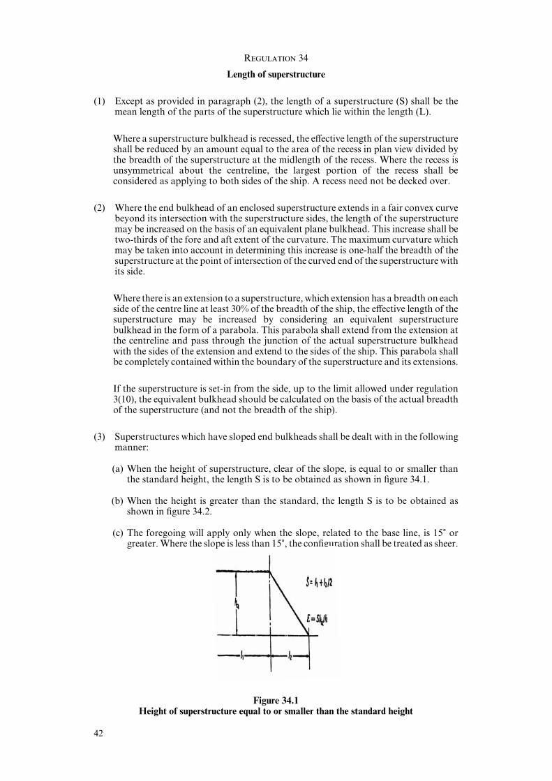
Regulation 34
Length of superstructure
(1) Except as provided in paragraph (2), the length of a superstructure (S) shall be themean length of the parts of the superstructure which lie within the length (L).
Where a superstructure bulkhead is recessed, the eVective length of the superstructureshall be reduced by an amount equal to the area of the recess in plan view divided bythe breadth of the superstructure at the midlength of the recess. Where the recess isunsymmetrical about the centreline, the largest portion of the recess shall beconsidered as applying to both sides of the ship. A recess need not be decked over.
(2) Where the end bulkhead of an enclosed superstructure extends in a fair convex curvebeyond its intersection with the superstructure sides, the length of the superstructuremay be increased on the basis of an equivalent plane bulkhead. This increase shall betwo-thirds of the fore and aft extent of the curvature. The maximum curvature whichmay be taken into account in determining this increase is one-half the breadth of thesuperstructure at the point of intersection of the curved end of the superstructure withits side.
Where there is an extension to a superstructure, which extension has a breadth on eachside of the centre line at least 30% of the breadth of the ship, the eVective length of thesuperstructure may be increased by considering an equivalent superstructurebulkhead in the form of a parabola. This parabola shall extend from the extension atthe centreline and pass through the junction of the actual superstructure bulkheadwith the sides of the extension and extend to the sides of the ship. This parabola shallbe completely contained within the boundary of the superstructure and its extensions.
If the superstructure is set-in from the side, up to the limit allowed under regulation3(10), the equivalent bulkhead should be calculated on the basis of the actual breadthof the superstructure (and not the breadth of the ship).
(3) Superstructures which have sloped end bulkheads shall be dealt with in the followingmanner:
(a) When the height of superstructure, clear of the slope, is equal to or smaller thanthe standard height, the length S is to be obtained as shown in figure 34.1.
(b) When the height is greater than the standard, the length S is to be obtained asshown in figure 34.2.
(c) The foregoing will apply only when the slope, related to the base line, is 15) orgreater. Where the slope is less than 15), the configuration shall be treated as sheer.
Figure 34.1Height of superstructure equal to or smaller than the standard height
42

Figure 34.2
Height of superstructure greater than the standard height
Regulation 35
EVective length of superstructure
(1) Except as provided for in paragraph (2), the eVective length (E) of an enclosedsuperstructure of standard height shall be its length.
(2) In all cases where an enclosed superstructure of standard height is set-in from the sidesof the ship as permitted in regulation 3(10), the eVective length shall be the lengthmodified by the ratio of b/Bs, where:
b is the breadth of the superstructure at the middle of its length; and
Bs is the breadth of the ship at the middle of the length of the superstructure.
Where a superstructure is set-in for a part of its length, this modification shall beapplied only to the set-in part.
(3) Where the height of an enclosed superstructure is less than the standard height, theeVective length shall be its length reduced in the ratio of the actual height to thestandard height. Where the height exceeds the standard, no increase shall be made tothe eVective length of the superstructure (see figures 34.1 and 34.2).
Where the height, clear of the slope, of a superstructure which has sloped endbulkheads is less than the standard height, its eVective length E shall be its length S asobtained from figure 34.1, reduced in the ratio of the actual height to the standardheight.
Where a poop or forecastle of less than standard height is fitted on a ship with excessivesheer but without any superstructure within 0.2L amidships, credit may be given tothe height of the poop or forecastle by increasing the actual height by the diVerencebetween the actual and the standard sheer profiles. The deduction for excess sheer inaccordance with regulation 38(16) is not to be granted.
(4) The eVective length of a raised quarter deck, if fitted with an intact front bulkhead,shall be its length up to a maximum of 0.6L. Where the bulkhead is not intact, theraised quarter deck shall be treated as a poop of less than standard height.
The maximum eVective length of 0.6L of a raised quarterdeck is to be measured fromthe after perpendicular, even where a poop is fitted in conjunction with the raisedquarterdeck.
(5) Superstructures which are not enclosed shall have no eVective length.
43

Regulation 36
Trunks(1) A trunk or similar structure which does not extend to the sides of the ship shall be
regarded as eYcient on the following conditions:
(a) the trunk is at least as strong as a superstructure;
(b) the hatchways are in the trunk deck, the hatchway coamings and covers complywith the requirements of regulations 13 to 16 inclusive and the width of the trunkdeck stringer provides a satisfactory gangway and suYcient lateral stiVness.However, small access openings with watertight covers may be permitted in thefreeboard deck;
(c) a permanent working platform fore and aft fitted with guard rails is provided bythe trunk deck, or by detached trunks connected to superstructures by eYcientpermanent gangways.
(d) ventilators are protected by the trunk, by watertight covers or by other equivalentmeans;
(e) open rails are fitted on the weather parts of the freeboard deck in way of the trunkfor at least half their length or, alternatively, freeing port area in the lower part ofthe bulwarks, subject to regulation 24(2), of 33% of the total area of the bulwarksis provided;
(f) the machinery casings are protected by the trunk, by a superstructure of at leaststandard height, or by a deckhouse of the same height and of equivalent strength;
(g) the breadth of the trunk is at least 60% of the breadth of the ship; and
(h) where there is no superstructure, the length of the trunk is at least 0.6L.
(2) The full length of an eYcient trunk reduced in the ratio of its mean breadth to B shallbe its eVective length.
(3) The standard height of a trunk is the standard height of a superstructure other thana raised quarter deck.
(4) Where the height of a trunk is less than the standard height, its eVective length shall bereduced in the ratio of the actual to the standard height. Where the height of hatchwaycoamings on the trunk deck is less than that required under regulation 14-1, areduction from the actual height of trunk shall be made which corresponds to thediVerence between the actual and the required height of coaming.
(5) Where the trunk height is less than standard and the trunk hatch coamings are alsoof less than standard height, or omitted entirely, the reduction from the actual heightof trunk on account of insuYcient hatch coaming height shall be taken as thediVerence between 600 mm and the actual height of coaming, or 600 mm if no hatchcoamings are fitted. Reduction in the actual height of trunk shall not be required incases where only small hatches with less than standard height are fitted in the trunkdeck for which dispensation from the requirement of standard coaming height maybe given.
(6) Continuous hatchways may be treated as a trunk in the freeboard computation,provided the provisions of this paragraph are complied with in all respects.
The trunk deck stringer referred to in paragraph (1)(b) may be fitted outboard of thetrunk side bulkhead in association with the following:
(a) the stringer so formed is to provide a clear walkway of at least 450 mm in widthon each side of the ship;
(b) the stringer is to be of solid plate, eYciently supported and stiVened;
(c) the stringer is to be as high above the freeboard deck as practicable. In thefreeboard calculation, the trunk height is to be reduced by at least 600 mm or bythe actual diVerence between the top of the trunk and the stringer, whichever isgreater;
44

(d) hatch cover securing appliances are to be accessible from the stringer or walkway;and
(e) the breadth of the trunk is to be measured between the trunk side bulkheads.
(7) Where the trunk adjoining the superstructures such as poop, bridge or forecastle isincluded in the calculation of freeboard, openings shall not be arranged in that partof the bulkhead which is common for the trunk and superstructure. A relaxation maybe made for small openings such as for piping, cable or manholes with covers attachedby means of bolts.
(8) The sides of a trunk included in the calculation of freeboard shall be intact. Sidescuttles of the non-opening type and bolted manhole covers may be allowed.
Regulation 37
Deduction for superstructures and trunks
(1) Where the eVective length of superstructures and trunks is l L, the deduction from thefreeboard shall be 350 mm at 24 m length of ship, 860 mm at 85 m length and 1,070mm at 122 m length and above. Deductions at intermediate lengths shall be obtainedby linear interpolation.
(2) Where the total eVective length of superstructures and trunks is less than 1L, thededuction shall be a percentage obtained from table 37.1:
Table 37.1
Percentage of deduction for type ‘A’ and ‘B’ ships
Total eVective length of superstructures and trunks
0 0.1 L 0.2 L 0.3 L 0.4 L 0.5 L 0.6 L 0.7 L 0.8 L 0.9 L 1 L
Percentage ofdeduction for 0 7 14 21 31 41 52 63 75.3 87.7 100all types ofsuperstructure
Percentages at intermediate lengths of superstructures and trunks shall be obtained by linear interpolation.
(3) For ships of type ‘B’ where the eVective length of a forecastle is less than 0.07L nodeduction is allowed.
Regulation 38
Sheer
General
(1) The sheer shall be measured from the deck at side to a line of reference drawn parallelto the keel through the sheer line amidships.
(2) In ships designed with a rake of keel, the sheer shall be measured in relation to areference line drawn parallel to the design load waterline.
(3) In flush deck ships and in ships with detached superstructures the sheer shall bemeasured at the freeboard deck.
(4) In ships with topsides of unusual form in which there is a step or break in the topsides,the sheer shall be considered in relation to the equivalent depth amidships.
(5) In ships with a superstructure of standard height which extends over the whole lengthof the freeboard deck, the sheer shall be measured at the superstructure deck. Wherethe height exceeds the standard, the least diVerence (Z) between the actual andstandard heights shall be added to each end ordinate. Similarly, the intermediate
45

ordinates at distances of 1/6L and 1/3L from each perpendicular shall be increased by0.444Z and 0.111Z, respectively. Where there is an enclosed poop or forecastlesuperimposed on the superstructure, sheer credit shall be allowed for such a poop orforecastle, according to the method of paragraph (12) as shown in figure 38.1.
Figure 38.1
(6) Where the deck of an enclosed superstructure has at least the same sheer as theexposed freeboard deck, the sheer of the enclosed portion of the freeboard deck shallnot be taken into account.
(7) Where an enclosed poop or forecastle is of standard height with greater sheer thanthat of the freeboard deck, or is of more than standard height, an addition to the sheerof the freeboard deck shall be made as provided in paragraph (12).
Where a poop or forecastle consists of two layers, the method shown in figure 38.2shall be used.
Figure 38.2
In figures 38.1 and 38.2, the following definitions apply:
Z is as defined in paragraph (5); and
Zv is the end ordinate of a virtual standard parabolic curve taken through thepoint “X”. If Zv is greater than (Z ! h), the end ordinate shall be (Z ! h),in which case point “X” shall be disregarded and curve (2) not taken intoaccount.
46

When the length of the first tier superstructure is greater than 0.5l, the virtual standardparabolic curve shall commence at amidships as indicated in figure 38.1.
Standard sheer profile
(8) The ordinates of the standard sheer profile are given in table 38.1:
Table 38.1
Standard sheer profile(where L is in m)
Station Ordinate Factor(in mm)
LAfter half After perpendicular 25 (— ! 10)3 1
L1/6 L from A.P. 311.1 (— ! 10)3
L1/3 L from A.P. 32.8 (— ! 10)3
Amidships 0 1
Forward half Amidships 0 1
L1/3 L from F.P. 35.6 (— ! 10)3L1/6 L from F.P. 322.2 (— ! 10)3
LForward perpendicular 150 (— ! 10)3
Measurement of variation from standard sheer profile
(9) Where the sheer profile diVers from the standard, the four ordinates of each profilein the forward or after half shall be multiplied by the appropriate factors given in theabove table of ordinates. The diVerence between the sums of the respective productsand those of the standard divided by 8 measures the deficiency or excess of sheer inthe forward or after half. The arithmetical mean of the excess or deficiency in theforward and after halves measures the excess or deficiency of sheer.
(10) Where the after half of the sheer profile is greater than the standard and the forwardhalf is less than the standard, no credit shall be allowed for the part in excess anddeficiency only shall be measured.
(11) Where the forward half of the sheer profile exceeds the standard, and the after portionof the sheer profile is not less than 75% of the standard, credit shall be allowed for thepart in excess. Where the after part is less than 50% of the standard no credit shall begiven for the excess sheer forward. Where the after sheer is between 50% and 75% ofthe standard, intermediate allowances may be granted for excess sheer forward.
(12) Where sheer credit is given for a poop or forecastle the following formula shall beused:
yL’s % ——
3L
where: s is the sheer credit, to be deducted from the deficiency, or added to theexcess of sheer;
Y is the diVerence between actual and standard height of superstructure atthe after or forward perpendicular;
47

L’ is the mean enclosed length of poop or forecastle up to a maximum lengthof 0.5 L; and
L is the length of the ship as defined in regulation 3(1).
The above formula provides a curve in the form of a parabola tangent to the actual sheercurve at the freeboard deck and intersecting the end ordinate at a point below thesuperstructure deck a distance equal to the standard height of a superstructure. Thesuperstructure deck shall not be less than standard height above this curve at any point.This curve shall be used in determining the sheer profile for forward and after halves ofthe ship.
(13) (a) Any excess in the height of a superstructure which does not extend to the afterperpendicular cannot be regarded as contributing to the sheer allowance.
(b) Where the height of a superstructure is less than standard, the superstructure deckshall not be less than the minimum height of the superstructure above the virtualshear curve at any point. For this purpose y shall be taken as the diVerencebetween the actual and minimum height of the superstructure at the after/forwardperpendicular.
(c) For a raised quarterdeck credit may be given only when the height of thisquarterdeck is greater than the standard height of ‘other superstructures’ asdefined in regulation 33, and only for the amount by which the actual height ofthe raised quarterdeck exceeds that standard height.
(d) When a poop or a forecastle has sloping end bulkheads, the sheer credit may beallowed on account of excess height. The formula given in paragraph (12) shallbe used, the values for y and L’ being as shown in figure 38.3.
Figure 38.3
Sheer credits for excess height
Correction for variations from standard sheer profile
(14) The correction for sheer shall be the deficiency or excess of sheer (see paragraphs (9)to (11) inclusive), multiplied by
S1
0.75 - ——2L
where S1 is the total length S of enclosed superstructures as defined in regulation 34without trunks.
Addition for deficiency in sheer
(15) Where the sheer is less than the standard, the correction for deficiency in sheer (seeparagraph (14)) shall be added to the freeboard.
Deduction for excess sheer
(16) In ships where an enclosed superstructure covers 0.1L before 0.1L abaft amidships,the correction for excess of sheer as calculated under the provisions of paragraph(14) shall be deducted from the freeboard; in ships where no enclosed superstructurecovers amidships, no deduction shall be made from the freeboard; where an enclosed
48

superstructure covers less than 0.1L before and 0.1L abaft amidships, the deductionshall be obtained by linear interpolation. The maximum deduction for excess sheershall be at the rate of 125 mm per 100 m of length.
In applying this paragraph, the height of the superstructure shall be related to itsstandard height. Where the height of the superstructure or raised quarterdeck is lessthan standard, the reduction shall be in the ratio of the actual to the standardheight thereof.
Regulation 39
Minimum bow height and reserve buoyancy
(1) The bow height (Fb), defined as the vertical distance at the forward perpendicularbetween the waterline corresponding to the assigned summer freeboard and thedesigned trim and the top of the exposed deck at side, shall be not less than:
Fb%(6075(L/100)"1875(L/100)2!200(L/100)3)X(2.08!0.609Cb"1.603Cwf"0.0129(L/d1))
where:
Fb is the calculated minimum bow height, in mm;
L is the length, as defined in regulation 3, in m;
B is the moulded breadth, as defined in regulation 3, in m;
d1 is the draught at 85% of the depth D, in m;
Cb is the block coeYcient, as defined in regulation 3;
Cwf is the waterplane area coeYcient forward of L/2: Cwf%Awf/a(L/2) x B];
Awf is the waterplane area forward of L/2 at draught d1, in m2.
For ships to which timber freeboards are assigned, the summer freeboard (and not thetimber summer freeboard) is to be assumed when applying paragraph (1).
(2) Where the bow height required in paragraph (1) is obtained by sheer, the sheer shallextend for at least 15% of the length of the ship measured from the forwardperpendicular. Where it is obtained by fitting a superstructure, such superstructureshall extend from the stem to a point at least 0.07L abaft the forward perpendicular,and shall be enclosed as defined in regulation 3(10).
(3) Ships which, to suit exceptional operational requirements, cannot meet therequirements of paragraphs (1) and (2) of this regulation may be given specialconsideration by the Administration.
(4) (a) The sheer of the forecastle deck may be taken into account, even if the length ofthe forecastle is less than 0.15L, but greater than 0.07L, provided that theforecastle height is not less than one half of standard height of superstructure asdefined in regulation 33 between 0.07L and the forward perpendicular.
(b) Where the forecastle height is less than one half of the standard height ofsuperstructure, as defined in regulation 33, the credited bow height may bedetermined as follows:
(i) Where the freeboard deck has sheer extending from abaft 0.15L, by aparabolic curve having its origin at 0.15L abaft the forward perpendicular ata height equal to the midship depth of the ship, extended through the point ofintersection of forecastle bulkhead and deck, and up to a point at the forwardperpendicular not higher than the level of the forecastle deck (as illustratedin figure 39.1). However, if the value of the height denoted ht in figure 39.1is smaller than the value of the height denoted hb then ht may be replaced byhb in the available bow height.
(ii) Where the freeboard deck has sheer extending for less than 0.15L or has nosheer, by a line from the forecastle deck at side at 0.07L extended parallel tothe base line to the forward perpendicular (as illustrated in figure 39.2).
49
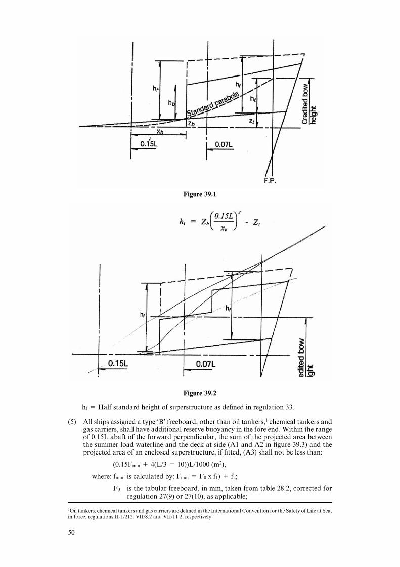
Figure 39.1
Figure 39.2
hf % Half standard height of superstructure as defined in regulation 33.
(5) All ships assigned a type ‘B’ freeboard, other than oil tankers,1 chemical tankers andgas carriers, shall have additional reserve buoyancy in the fore end. Within the rangeof 0.15L abaft of the forward perpendicular, the sum of the projected area betweenthe summer load waterline and the deck at side (A1 and A2 in figure 39.3) and theprojected area of an enclosed superstructure, if fitted, (A3) shall not be less than:
(0.15Fmin ! 4(L/3 % 10))L/1000 (m2),
where: fmin is calculated by: Fmin % F0 x f1) ! f2;
F0 is the tabular freeboard, in mm, taken from table 28.2, corrected forregulation 27(9) or 27(10), as applicable;
1Oil tankers, chemical tankers and gas carriers are defined in the International Convention for the Safety of Life at Sea,in force, regulations II-1/212. VII/8.2 and VII/11.2, respectively.
50
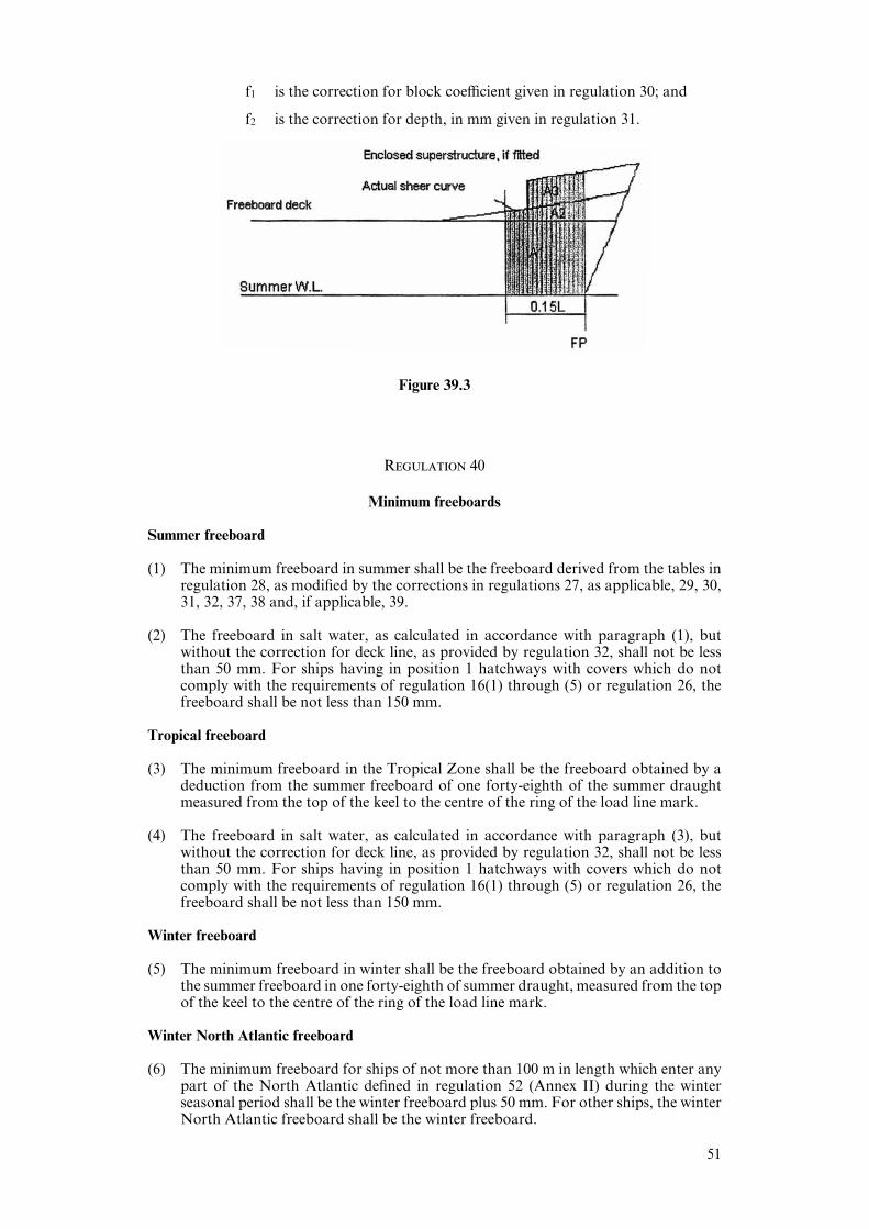
f1 is the correction for block coeYcient given in regulation 30; and
f2 is the correction for depth, in mm given in regulation 31.
Figure 39.3
Regulation 40
Minimum freeboards
Summer freeboard
(1) The minimum freeboard in summer shall be the freeboard derived from the tables inregulation 28, as modified by the corrections in regulations 27, as applicable, 29, 30,31, 32, 37, 38 and, if applicable, 39.
(2) The freeboard in salt water, as calculated in accordance with paragraph (1), butwithout the correction for deck line, as provided by regulation 32, shall not be lessthan 50 mm. For ships having in position 1 hatchways with covers which do notcomply with the requirements of regulation 16(1) through (5) or regulation 26, thefreeboard shall be not less than 150 mm.
Tropical freeboard
(3) The minimum freeboard in the Tropical Zone shall be the freeboard obtained by adeduction from the summer freeboard of one forty-eighth of the summer draughtmeasured from the top of the keel to the centre of the ring of the load line mark.
(4) The freeboard in salt water, as calculated in accordance with paragraph (3), butwithout the correction for deck line, as provided by regulation 32, shall not be lessthan 50 mm. For ships having in position 1 hatchways with covers which do notcomply with the requirements of regulation 16(1) through (5) or regulation 26, thefreeboard shall be not less than 150 mm.
Winter freeboard
(5) The minimum freeboard in winter shall be the freeboard obtained by an addition tothe summer freeboard in one forty-eighth of summer draught, measured from the topof the keel to the centre of the ring of the load line mark.
Winter North Atlantic freeboard
(6) The minimum freeboard for ships of not more than 100 m in length which enter anypart of the North Atlantic defined in regulation 52 (Annex II) during the winterseasonal period shall be the winter freeboard plus 50 mm. For other ships, the winterNorth Atlantic freeboard shall be the winter freeboard.
51

Fresh water freeboard
(7) The minimum freeboard in fresh water of unit density shall be obtained by deductingfrom the minimum freeboard in salt water:
Δ(cm)
40T
where: Δ is the displacement in salt water in tonnes at the summer loadwaterline; and
T is the tonnes per centimetre immersion in salt water at thesummer load waterline.
(8) Where the displacement at the summer load waterline cannot be certified, thededuction shall be one forty-eight of summer draught, measured from the top of thekeel to the centre of the ring of the load line mark.
Chapter IV
Special Requirements for Ships Assigned Timber Freeboard
Regulation 41
Application of this chapter
Regulations 42 to 45 inclusive apply only to ships to which timber load lines are assigned.
Regulation 42
Definitions
(1) Timber deck cargo. The term “timber deck cargo” means a cargo of timber carriedon an uncovered part of a freeboard deck. The term does not include wood pulp orsimilar cargo.
(2) Timber load line. A timber deck cargo may be regarded as giving a ship a certainadditional buoyancy and a greater degree of protection against the sea. For thatreason, ships carrying a timber deck cargo may be granted a reduction of freeboardcalculated according to the provisions of regulation 45 and marked on the ship’s sidein accordance with the provisions of regulations 6(3) and (4). However, in order thatsuch special freeboard may be granted and used, the timber deck cargo shall complywith certain conditions which are laid down in regulation 44, and the ship itself shallalso comply with certain conditions relating to its construction which are set out inregulation 43.
Regulation 43
Construction of the ship
Superstructure
(1) Ships shall have a forecastle of at least standard height and a length of at least 0.07L.In addition, if the ship is less than 100 m in length, a poop of at least standard height,or a raised quarterdeck with a deckhouse of at least the same total height shall befitted aft.
52

Double bottom tanks
(2) Double bottom tanks, where fitted within the midship half length of the ship, shallhave adequate watertight longitudinal subdivision.
Bulwarks
(3) The ship shall be fitted either with permanent bulwarks at least 1 m in height, speciallystiVened on the upper edge and supported by strong bulwark stays attached to thedeck and provided with necessary freeing ports, or with eYcient rails of the sameheight and of specially strong construction.
Regulation 44
Stowage
General
(1) Openings in the deck exposed to weather over which cargo is stowed shall be securelyclosed and battened down.
The ventilators and air pipes shall be eYciently protected.
(2) Timber deck cargoes shall extend over at least the entire available length which is thetotal length of the well or wells between supersructures.
Where there is no limiting supersructure at the after end, the timber shall extend atleast to the after end of the aftermost hatchway.
The timber deck cargo shall extend athwartships as close as possible to the ship’s side,due allowance being made for obstructions such as guard rails, bulwark stays,uptrights, pilot access, etc., provided that any gap thus created at the side of the shipshall not exceed a mean of 4% of the breadth. The timber shall be stowed as solidlyas possible to at least the standard height of the superstructure other than any raisedquarterdeck.
(3) On a ship within a seasonal winter zone in winter, the height of the deck cargo abovethe deck exposed to weather shall not exceed one third of the extreme breadth ofthe ship.
(4) The timber deck cargo shall be compactly stowed, lashed and secured. It shall notinterfere in any way with the navigation and necessary work of the ship.
Uprights
(5) Uprights, when required by the nature of the timber, shall be of adequate strengthconsidering the breadth of the ship; the strength of the uprights shall not exceed thestrength of the bulwark and the spacing shall be suitable for the length and characterof timber carried, but shall not exceed 3 m. Strong angles or metal sockets or equallyeYcient means shall be provided for securing the uprights.
Lashings
(6) Timer deck cargo shall be eVectively secured throughout its length by a lashing systemacceptable to the Administration for the character of the timber carried.
Stability
(7) Provision shall be made for a safe margin of stability at all stages of the voyage, regardbeing given to additions of weight, such as those arising from absorption of water oricing, if applicable, and to losses of weight such as those arising from consumption offuel and stores.
1Reference is made to the Code of Safe Practice for Ships Carrying Timber Deck Cargoes, adopted by the Organizationby resolution A.715(17), as amended.
53

Protection of crew, access to machinery spaces, etc.
(8) In addition to the requirements of regulation 25(5), guard-rails or lifelines not morethan 350 mm apart vertically shall be provided on each side of the cargo deck to aheight of at least 1 m above the cargo.
In addition a lifeline, preferably wire rope set up taut with a stretching screw, shall beprovided as near as practicable to the centreline of the ship. The stanchion supportsto all guard-rails and lifelines shall be so spaced as to prevent undue sagging. Wherethe cargo is uneven, a safe walking surface of not less than 600 mm in width shall befitted over the cargo and eVectively secured beneath or adjacent to the lifeline.
(9) Where the requirements prescribed in paragraph (8) are impracticable, alternativearrangements satisfactory to the Administration shall be used.
Steering arrangements
(10) Steering arrangements shall be eVectively protected from damage by cargo and, asfar as practicable, shall be accessible. EYcient provision shall be made for steeringin the event of a breakdown in the main steering arrangements.
Regulation 45
Computation for freeboard
(1) The minimum summer freeboards shall be computed in accordance with regulations27(5), 27(6), 27(14), 28, 29, 30, 31, 32, 37 and 38, except that regulation 37 is modifiedby substituting the following percentages for those given in regulation 37:
Total eVective length of superstructure0 0.1L 0.2L 0.3L 0.4L 0.5L 0.6L 0.7L 0.8L 0.9L 1.0L
Percentage ofdeduction for alltypes of 20 31 42 53 64 70 76 82 88 94 100superstructure
Percentages at intermediate lengths of superstructure shall be obtained by linearinterpolation.
Table 45.1
(2) The Winter Timber Freeboard shall be obtained by adding to the Summer TimberFreeboard one thirty-sixth of the moulded summer timber draught.
(3) The Winter North Atlantic Timber Freeboard shall be the same as the Winter NorthAtlantic Freeboard prescribed in regulation 40(6).
(4) The Tropical Timber Freeboard shall be obtained by deducing from the SummerTimber Freeboard one forty-eighth of the moulded summer timber draught.
(5) The Fresh Water Timber Freeboard shall be computed in accordance with regulation40(7), based on the summer timber load waterline or with regulation 40(8), based onthe summer timber draught measured from the top of the keel to the summer timberload line.
54
(6) Timber freeboards may be assigned to ships with reduced type ‘B’ freeboards,provided the timber freeboards are calculated on the basis of the ordinary type ‘B’freeboard.
(7) The Timber Winter mark and/or the Timber Winter North Atlantic mark shall beplaced at the same level as the reduced type ‘B’ Winter mark when the computedTimber Winter mark and/or the computed Timber Winter North Atlantic mark fallbelow the reduced type ‘B’ Winter mark.”
ANNEX II
ZONES, AREAS AND SEASONABLE PERIODS
Regulation 49
Seasonal tropical areas
2 The existing text of paragraph 7(b) is replaced by the following:
“(b) An area bounded:
on the north and east by the southern boundary of the Tropical Zone;
on the south by the parallel of latitude of 24)S from the east coast of Australiato longitude 154)E, thence by the meridian of longitude 154)E to the Tropicof Capricorn and thence by the Tropic of Capricorn to longitude 150)W,thence by the meridian of longitude 150)W to latitude 20)S and thence by theparallel of latitude 20)S to the point where it intersects the southern boundaryof the Tropical Zone; and
on the west by the boundaries of the area within the Great Barrier Reefincluded in the Tropical Zone and by the east coast of Australia.
Seasonal periods:
TROPICAL: 1 April to 30 November
SUMMER: 1 December to 31 March.”
Printed in the UK by The Stationery OYce Limited on behalf of
the Controller of Her Majesty’s Stationery OYce
ID184029 322705 3/06 19585
55

ISBN 0-10-167562-3
9 780101 675628

Published by TSO (The Stationery Office) and available from:
Onlinewww.tso.co.uk/bookshop
Mail, Telephone Fax & E-mailTSOPO Box 29, Norwich, NR3 1GNTelephone orders/General enquiries 0870 600 5522order though the Parliamentary Hotline Lo-Call 0845 7 023474Fax orders 0870 600 5533E-mail book.orderswtso.co.ukTextphone 0870 240 3701
TSO Shops123 Kingsway, London WC2B 6PQ020 7242 6393 Fax 020 7242 639468–69 Bull Street, Birmingham B4 6AD0121 236 9696 Fax 0121 236 96999–21 Princess Street, Manchester M60 8AS0161 834 7201 Fax 0161 833 063416 Arthur Street, Belfast BT1 4GD028 9023 8451 Fax 028 9023 540118–19 High Street, Cardiff CF10 1PT029 2039 5548 Fax 029 2038 434771 Lothian Road, Edinburgh EH3 9AZ0870 606 5566 Fax 0870 606 5588
TSO Accredited Agents(see Yellow Pages)
and through good booksellers
ISBN 0 10 167562 3