2003-09 Smart transport : a survey of tracking …Calhoun: The NPS Institutional Archive Theses and...
86
Calhoun: The NPS Institutional Archive Theses and Dissertations Thesis Collection 2003-09 Smart transport : a survey of tracking technologies for cargo containers & their transport platforms Williams, Jeffrey L. Monterey, California. Naval Postgraduate School http://hdl.handle.net/10945/6250
Transcript of 2003-09 Smart transport : a survey of tracking …Calhoun: The NPS Institutional Archive Theses and...
Calhoun: The NPS Institutional Archive
Theses and Dissertations Thesis Collection
2003-09
Smart transport : a survey of tracking
technologies for cargo containers &
their transport platforms
Williams, Jeffrey L.
Monterey, California. Naval Postgraduate School
http://hdl.handle.net/10945/6250

MONTEREY, CALIFORNIA
THESIS
SMART TRANSPORT-A SURVEY OF TRACKING TECHNOLOGIES FOR CARGO CONTAINERS AND
THEIR TRANSPORT PLATFORMS
by
Jeffrey L. Williams
September 2003 Thesis Advisor: Dan C. Boger Second Reader: J. L. Fobes
Approved for public release; distribution unlimited

THIS PAGE INTENTIONALLY LEFT BLANK

REPORT DOCUMENTATION PAGE Form Approved OMB No. 0704-0188 Public reporting burden for this collection of information is estimated to average 1 hour per response, including the time for reviewing instruction, searching existing data sources, gathering and maintaining the data needed, and completing and reviewing the collection of information. Send comments regarding this burden estimate or any other aspect of this collection of information, including suggestions for reducing this burden, to Washington headquarters Services, Directorate for Information Operations and Reports, 1215 Jefferson Davis Highway, Suite 1204, Arlington, VA 22202-4302, and to the Office of Management and Budget, Paperwork Reduction Project (0704-0188) Washington DC 20503. 1. AGENCY USE ONLY (Leave blank)
2. REPORT DATE September 2003
3. REPORT TYPE AND DATES COVERED Master’s Thesis
4. TITLE AND SUBTITLE: Smart Transport: A Survey of Tracking Technologies for Cargo Containers and Their Transport Platforms 6. AUTHOR(S) Jeffrey L. Williams
5. FUNDING NUMBERS
7. PERFORMING ORGANIZATION NAME(S) AND ADDRESS(ES) Naval Postgraduate School Monterey, CA 93943-5000
8. PERFORMING ORGANIZATION REPORT NUMBER
9. SPONSORING /MONITORING AGENCY NAME(S) AND ADDRESS(ES) National Security Agency, Applied Technology Division 9800 Savage Rd. Fort George G. Meade, MD 20755
10. SPONSORING/MONITORING AGENCY REPORT NUMBER
11. SUPPLEMENTARY NOTES The views expressed in this thesis are those of the author and do not reflect the official policy or position of the Department of Defense or the U.S. Government. 12a. DISTRIBUTION / AVAILABILITY STATEMENT Approved for public release; distribution is unlimited
12b. DISTRIBUTION CODE A
13. ABSTRACT (maximum 200 words)
As the threat of terrorism rises, nations seek solutions to secure their ports and lanes of commerce upon the world’s oceans and skies. The transport industry has taken the lead in developing new technologies to track cargo containers and the transport platforms, for billions of dollars are at stake. This thesis examines the present and future communication and tracking systems used by the transport industry. Furthermore, an investigation into the tracking methods for high value items such as diamonds will be disclosed. By analyzing the communication and tracking systems used by the transport industry, elements of the Homeland Security organization can mitigate terrorism on the lanes of commerce and ultimately prevent weapons of mass destruction from entering the United States.
15. NUMBER OF PAGES
85
14. SUBJECT TERMS Cargo Container Tracking, Radio Frequency Identification, E-Seals, Satellites, Diamonds
16. PRICE CODE
17. SECURTIY CLASSIFICATION OF REPORT
Unclassified
18. SECURITY CLASSIFICATION OF THIS PAGE
Unclassified
19. SECURITY CLASSIFICATION OF ABSTRACT
Unclassified
20. LIMITATION OF ABSTRACT
UL
NSN 7540-01-280-5500 Standard Form 298 (Rev. 2-89) Prescribed by ANSI Std. 239-18
i

THIS PAGE INTENTIONALLY LEFT BLANK
ii

Approved for public release, distribution is unlimited
SMART TRANSPORT A SURVEY OF TRACKING TECHNOLOGIES FOR CARGO CONTAINERS
AND THEIR TRANSPORT PLATFORMS
by
Jeffrey L. Williams Lieutenant, United States Navy
B.S., United States Naval Academy, 1994
Submitted in partial fulfillment of the requirement for the degree of
MASTER OF SCIENCE IN SYSTEMS ENGINEERING
from the
NAVAL POSTGRADUATE SCHOOL September 2003
Author: Jeffrey L. Williams
Approved by: Dan C. Boger
Thesis Advisor
J. L. Fobes Second Reader
Dan C. Boger Chairman, Department of Information Sciences
iii

THIS PAGE INTENTIONALLY LEFT BLANK
iv

ABSTRACT As the threat of terrorism rises, nations seek solutions to secure their ports and
lanes of commerce upon the world’s oceans and skies. The transport industry has taken
the lead in developing new technologies to track cargo containers and the transport
platforms, for billions of dollars are at stake. This thesis examines the present and future
communication and tracking systems used by the transport industry. Furthermore, an
investigation into the tracking methods for high-value items such as diamonds will be
disclosed. By analyzing the communication and tracking systems used by the transport
industry, elements of the Homeland Security organization can mitigate terrorism on the
lanes of commerce and ultimately prevent weapons of mass destruction from entering the
United States.
v

THIS PAGE INTENTIONALLY LEFT BLANK
vi

TABLE OF CONTENTS
I. INTRODUCTION........................................................................................................1 A. STRATEGIC CONTEXT ...............................................................................1 B. SUMMARY OF RESEARCH ........................................................................2
II. TRACKING SYSTEMS FOR CARGO.....................................................................5 A. SATELLITE SYSTEMS .................................................................................5
1. NAVSTAR GPS and GLONASS........................................................5 2. European Geostationary Navigation Overlay Service......................5 3. Galileo ...................................................................................................7 4. ORBCOMM .........................................................................................7 5. Argos ...................................................................................................10 6. Inmarsat..............................................................................................11
B. RADIO FREQUENCY IDENTIFICATION (RFID) SYSTEMS..............12 1. RFID Tags for Intermodal Containers ............................................12 2. E-Seals.................................................................................................15
C. TRACKING SYSTEMS FOR AIR CARGO ..............................................18 1. Web-Based Systems ...........................................................................18 2. RFID Tags on ULDs ..........................................................................19
D. PAPER TRAIL...............................................................................................19 1. Bill of Lading ......................................................................................19 2. Letter of Credit ..................................................................................22
E. DEFEATING TRACKING SYSTEMS AND E-SEALS............................25 1. GPS......................................................................................................25 2. Circumventing or Defeating E-Seals or Tracking Tags .................26 3. Automated Information Systems......................................................27
F. SUMMARY ....................................................................................................27
III. TRACKING SYSTEMS FOR SHIPS AND AIRCRAFT ......................................29 A. SATELLITE SYSTEMS ...............................................................................29
1. Inmarsat..............................................................................................29 2. Iridium ................................................................................................30 3. Eutelsat................................................................................................31 4. Globalstar ...........................................................................................32 5. Thuraya...............................................................................................34 6. New ICO .............................................................................................35 7. Ellipso..................................................................................................36
B. HUMAN AGENTS.........................................................................................37 C. AUTOMATIC IDENTIFICATION SYSTEM (AIS) .................................37 D. DIGITAL SELECTIVE SERVICE (DSC)..................................................39 E. SUMMARY ....................................................................................................39
IV. METHODS FOR TRACKING UNIQUE ITEMS..................................................41
viiA. DIAMONDS ...................................................................................................41

1. Illicit Trade of Diamonds ..................................................................41 2. Tracing Rough Diamonds .................................................................42 3. Tracing Polished Diamonds ..............................................................43 4. Kimberly Process ...............................................................................43
B. INTERNATIONAL BANK CHECKS.........................................................45 1. Telex ....................................................................................................45 2. SWIFTnet ...........................................................................................47
C. SUMMARY ....................................................................................................47
V. CONCLUSION ..........................................................................................................49 A. APPLICATIONS ...........................................................................................49
1. Maritime Tracking System ...............................................................49 2. Telex Coverage ...................................................................................50 3. Pushing E-Seals and RFID Development ........................................50
B. AREAS FOR FURTHER STUDY ...............................................................50 1. Relatively New Satellite Systems ......................................................50 2. More Spoofing Required ...................................................................51 3. Combination of Satellite and RFID Tracking System....................51
C. SUMMARY OF WORK................................................................................52
APPENDIX A. SATELLITE CHARACTERISTICS...............................................53
APPENDIX B. VENDOR LIST ..................................................................................55
LIST OF REFERENCES......................................................................................................63
INITIAL DISTRIBUTION LIST .........................................................................................69
viii

LIST OF FIGURES
Figure 1. Possible ORBCOMM Network Configuration (After: Ref 8)..........................9 Figure 2. Possible RFID Setup in a Container Terminal (After: Ref 15)......................14 Figure 3. Unique Placement of All Set E-Seal (From: Ref 21)......................................18 Figure 4. Bill of Lading (From: Ref 27).........................................................................21 Figure 5. Letter of Credit (From: Ref 29) ......................................................................24 Figure 6. Globalstar Coverage (From: Ref 39) ..............................................................33 Figure 7. Thuraya Coverage Map (From: Ref 42) .........................................................35 Figure 8. Snap Shot of the World Diamond Industry (From: Ref 50) ...........................42 Figure 9. Diamond Fingerprinting (From: Refs 52 and 53) ...........................................43
ix

THIS PAGE INTENTIONALLY LEFT BLANK
x

LIST OF TABLES
Table 1. Electronic Seals & RFID Frequencies (Ref 20)...............................................16
xi

THIS PAGE INTENTIONALLY LEFT BLANK
xii

ACKNOWLEDGMENTS The author would like to thank Prof. Boger and Prof. Fobes for their support and
guidance throughout this project. Thanks also goes to Nathan Beltz for his vital support
in the lab and to Nancy Sharrock for her most needed and appreciated MS Word template
skills. Finally, the author would like to express his humble thanks for the Lord’s blessing
of this work, and his deepest respect and love for Sheeba, Felix, and Dr. Mary Ring.
With their support, this mission was accomplished.
xiii

THIS PAGE INTENTIONALLY LEFT BLANK
xiv

I. INTRODUCTION
A. STRATEGIC CONTEXT In the wake of September 11, 2001 (9-11) the internal security of the United
States has again been thrust onto the national conscience. Like the infamous day of
December 7,1941, the Japanese attack on Pearl Harbor, 9-11 has reminded us how truly
vulnerable the country is to the evil of the world.
The nation’s response to prevent another attack such as Pearl Harbor was to
develop long-range radars that would provide plenty of warning of an attack from a
squadron of aircraft or missiles, which were headed for our shores. In addition, the
country developed an intelligence system that scours the world for information that
would determine which countries were hostile to the United States (US). These systems
enable us to find diplomatic solutions before tensions escalate to the level that another
country would attack and also provide us the lead time and knowledge to carry the war to
an aggressor state’s front door.
However, 9-11 has cast light on a new aggressor, the terrorist. Terrorist groups
are not nation states and do not possess the means of carrying out conventional warfare.
They study our weaknesses within the US borders. They look at the transportation
industry as a vehicle for terror to deliver a crushing blow to the US economy and national
psyche.
September 11th proved that the country’s airline industry was susceptible to
terrorism and measures have been taken to mitigate any weaknesses within the airline
system. In addition, 9-11 has brought about deep concerns for the security of the nation’s
ports. The most prevalent concern has been that a terrorist would attempt to smuggle a
Weapon of Mass Destruction (WMD) into the country through a cargo container shipped
from overseas. Knowing that drugs and illegal aliens are routinely smuggled into the
country amongst other legitimate cargo on large commercial ships, this concern becomes
very realistic and a potential nightmare for the nation.
Furthermore the General Accounting Office reports,
1

More than 95 percent of our non-North American foreign trade arrives by ship. In 2001, approximately 5400 ships carrying multinational crews and cargoes from around the globe made more than 60000 US port calls. More than 6 million containers enter the country annually [Ref 1].
These numbers indicate that terrorists have ample opportunity to deliver a WMD to one
of the nation’s ports.
If a WMD were detonated in one of the nation’s major ports, the economic effect
would be devastating. The nation got an early glimpse of the economic woes associated
with the closure of a port during the labor conflict at West Coast ports in early October
2002. During the 10-day strife between management and dockworkers, it was estimated
that the economy might have lost $19.4 billion. Furthermore, not only was the US
economy affected, but Asian manufacturers considered stopping production because their
products were stacking up on the docks in Asian ports [Ref 2]. Thus, due to the
interdependence of world trade, the longtime closure of American ports can have grave
effects upon the global economy.
Due to the potential grave economic losses, the United States government and the
maritime industry have taken significant steps to improve security of ports and cargo
containers. Programs such as the Smart & Secure Tradelanes Initiatives, US Customs
Service’s Container Security Initiative, and Operation Safe Commerce are government
and industry partnerships aimed at enhancing cargo security and efficiency along the
global supply chain. The emphasis of these programs is to use or develop technologies to
ensure that the cargo container is tamper proof and can be tracked from its place of origin
to its final destination.
B. SUMMARY OF RESEARCH The maritime and container industries worldwide have developed a number of
technologies to track intermodal cargo containers from the time the container enters a
terminal or dock to which transport platform it is loaded on and to its final destination.
Many of the tracking technologies have been developed in North America and Europe.
The tracking technologies being developed are broadly divided into two categories,
satellite- based and infrastructure-based. Satellite tracking systems use Global
Positioning Satellites (GPS), communications satellites, Global Standard for Mobile
2

telephony (GSM) and the Internet to relay information from containers, ships, or aircraft
to the shipper and the carrier. Infrastructure-based systems use radio tags, tag readers,
802.11b wireless technology, Bluetooth Lite, GSM and the Internet to relay data from a
service provider to the shipper and the carrier. Note that there are different combinations
for the makeup of a satellite or infrastructure-based system, thus all elements listed above
for the respective tracking system may not be present.
These technologies are implemented to improve efficiency, customer service, and
security. The technologies allow transport companies to identify containers that are in a
low use area and transfer them to a high use area. Idle containers or the transport of
empty containers cost the transport companies money. The transport company can
communicate directly with customers to relay the status of refrigerated or hazardous
containers or indicate whether the shipment will be delivered on time. Customers can be
alerted if the containers are damaged or compromised. The physical appearance of the
tracking devices mounted on the containers deters unauthorized entries that result in theft,
smuggling, and illegal immigration. As governments recognize the security benefits of
tracking technologies and as their cost to be implemented become less for transport
companies, the equipment will permeate throughout the market.
This thesis examines existing and future tracking and communication systems
used to track cargo platforms and the cargo containers. The methodology involves a
survey of the existing tracking systems and those planned for the future. In addition, the
thesis will attempt to report on the tracking schemes used in unique/high value shipments,
such as raw diamonds and international bank checks for clearance. Investigating the
tracking and communication systems used to trace cargo and transport platforms may
give elements of Homeland Security the ability to mitigate terrorism and prevent the
transport of WMD into the United States.
Chapter II is a presentation of tracking systems for shipboard and airborne cargo.
The technologies covered are satellite systems, radio identification systems, web-based
systems, and the administrative trail created by the elements of the bill of lading and
letter of credit. In addition, methods of how to defeat tracking systems, e-seals, and
RFID tags are discussed.
3

Chapter III details the tracking systems for ships and aircraft. Satellite systems,
radio systems, and human agent organizations are covered in this section.
Chapter IV depicts the methods for tracking unique or high value items. Tracking
technologies for these items will concentrate on methods and processes used to trace
items such as diamonds and international bank checks.
Chapter V covers areas in which the information within this thesis can be applied
and proposes areas in which further study should be explored.
4

II. TRACKING SYSTEMS FOR CARGO
A. SATELLITE SYSTEMS Satellite tracking systems are made up of two separate satellite networks used for
determining positions and communicating data. Thus, the systems are respectively called
Positioning and Communication Satellites.
1. NAVSTAR GPS and GLONASS
There are currently two positioning satellite systems that are operating today, the
Navigation Signaling and Timing Global Positioning System (NAVSTAR GPS) operated
by the United States Air Force and the Global Orbiting Navigation Satellite System
(GLONASS) operated by the Russian Space Forces. Both of these systems have a 24-
satellite network broken into 6 clusters (4 satellites per cluster) orbiting in a Medium
Earth Orbit (MEO) and each transmits in the L band. GPS transmits the Standard
Positioning Service (SPS) signal at 1572.4 MHz and GLONASS transmits the Standard
Precision signal (SP) at 1602 MHz. Both of the satellite navigation systems are capable
of transmitting signals which provide greater accuracy than SPS and SP. However, the
SPS and the SP signals are available to all GPS users on a continuous, worldwide basis as
were the GPS Precise Positioning Service (PPS) and the GLONASS High Precision (HP)
signals are limited to military use. To calculate position, commercial GPS receivers
capture the SPS or SP signals; the receiver multiplies the time it took for the signal to
reach the receiver by the speed of light to determine how far the signal traveled. This
calculation is completed four times for each satellite in a respective cluster and through a
process called trilateration in which the receiver uses to deduce its position [Refs 3 and
4].
2. European Geostationary Navigation Overlay Service
The position determined by the receiver is usually within 20 meters of the actual
position. To obtain a more accurate position an individual or entity may use a receiver
capable of receiving Differential GPS Signals (DGPS). A DGPS signal contains the true
position and measured position. The difference between these two measurements is
designated as the differential corrected distance. This corrected distance can be stored in
5

the base station or sent to the receiver. When the receiver obtains the SPS or SP signal
from each of the satellites, the receiver subtracts the differential correction from the
estimated distance to each satellite to improve position accuracy.
DGPS can be derived by a combination of satellite and land-based systems or two
different satellite constellations. Currently, DGPS is derived by using land-based and
systems. The GPS signal is received at a land station that knows its exact location. The
known location is compared with the received GPS signal, the corrected distance is
calculated and the corrected signal is forwarded from the land station to everyone within
the land station’s region. Nonetheless, the European Space Agency, European
Commission, and EUROCONTROL, the European Organization for the Safety of Air
Navigation, are developing a system called the European Geostationary Navigation
Overlay Service (EGNOS), which is based on a separate satellite system calculating
DGPS. EGNOS will be fully functional by 2004.
EGNOS is being developed to ensure better accuracy and service. The premise of
EGNOS is to provide uninterrupted reliable and accurate positioning data to safety
critical applications such as aviation navigation. The accuracy of positions will improve
from 20 meters to 5 meters. In addition, the signal from this system will carry the
accuracy of the position of each GPS and GLONASS satellite, the accuracy of atomic
clocks onboard the satellites, and information on disturbances within the ionosphere that
might affect the accuracy of positioning measurement. Thus, the EGNOS system
provides not only position data, but also a sense of reliability.
The EGNOS system is made up of three geostationary satellites and a network of
ground stations. The constellation will send out ranging signals worldwide like those
transmitted by GPS and GLONASS constellations via two Inmarsat-3 satellites, one over
the eastern part of the Atlantic, the other over the Indian Ocean, and ESA Artemis
satellite, which is above Africa. These birds do not have signal generators on board, thus
the system will depend on a ground processing station to up-link the finished signal.
Currently the EGNOS system depends on the positioning signals received from
GPS and GLONASS satellites. Through thirty Ranging and Integrity Monitoring
Stations (RIMS), the measured positions of EGNOS, GPS, and GLONASS satellite are
6

processed and sent to four master control centers that determine the accuracy of GPS and
GLONASS signals received at each station and determines position inaccuracies due to
disturbances in the ionosphere. After all the deviations are calculated and integrated into
the signal, the signal is sent via secure communications to six uplink stations throughout
Europe. The uplink stations send the signal to EGNOS satellites, which then transmits
the signal to users with EGNOS receivers [Ref 5].
3. Galileo
In the future EGNOS will get positioning data from a European owned global
navigation satellite system called Galileo. Galileo will be very similar to GPS and
GLONASS constellations. Thus, there will be 30 satellites in a MEO, in which three are
spares. The first launch is scheduled for 2004 and full operational capability is scheduled
for 2008 [Ref 6].
Currently, the aviation community does not sanction existing positioning satellites
for use in aviation navigation because both GPS and GLONASS is owned and operated
by the countries’ respective militaries. Because the militaries have control there is no
guarantee that the two systems will always be available to provide service. Thus, Europe
has set out to develop a civilian owned system. In addition, Galileo’s technology will
provide accuracies up to one meter and cover the latitudes up to 75 degrees North.
Having the capability of producing one meter accuracy and assuring the service is always
available makes the system suitable for aviation navigation, running trains, and guiding
cars on future automated highways [Ref 7].
4. ORBCOMM
As mentioned at the beginning of this chapter, a satellite tracking system consists
of a GPS satellite system and a communication satellite system. For the remainder of this
chapter the focus will be on communication satellite systems. One of the most popular
communication satellite systems used for tracing containers is the ORBCOMM system
which is based in Dulles, VA.
ORBCOMM is made up of 30 Low Earth Orbit (LEO) satellites and terrestrial
gateways deployed around the world. Using a Subscriber Communicator (SC), GPS
7

signals are read from positioning satellites and relayed along with other data such as
temperature, pressure, tank levels, alarms and flow rate into the ORBCOMM
communication network via its satellites. The data are then down linked to a Gateway
Earth Station (GES) if originated in the United States or through an international
Gateway Control Center (GCC) if the data originated outside of the US. The GES or
GCC then relays the message via satellite link or dedicated terrestrial line to a Network
Control Center (NCC). The NCC routes the message to the final addressee via e-mail,
dedicated telephone line or facsimile. Depending on the type of SC and location, the unit
may be able to talk to GSM, radio and satellite communication systems. Because the
system works in two directions it is possible to send data to the container via the Internet
and ORBCOMM constellation. Note data sent via the ORBCOMM system are not for
large data files or real-time interactive sessions. Figure 1 illustrates a possible
ORBCOMM network configuration [Ref 8].
ORBCOMM’s operations in Europe are spear headed by MCS Europe, based in
the Netherlands. MCS Europe is responsible for encouraging the use of ORBCOMM
services, managing terrestrial infrastructure, and assisting Value-Added Resellers (VAR).
There are 31 VARs listed on the ORBCOMM website that are the middlemen between
customers and ORBCOMM. The VARs provide industries with tailored expertise,
solutions, and customer support to end-users. VARs’ solutions have targeted customers
that have reefer trailers, reefer containers, tank containers, road tanks, rail wagons,
vessels, box containers and private cars. See a list of value added resellers and service
providers in Appendix B for ORBCOMM and other communication satellites. In
addition, Appendix A provides a listing of the characteristics for all of the
communication satellites discussed in this thesis [Ref 8].
8

Figure 1. Possible ORBCOMM Network Configuration (After: Ref 8)
9

5. Argos
The Argos system was established in 1978 under a Memorandum of
Understanding between the National Oceanic and Atmospheric Administration (NOAA),
NASA, and the French Space Agency. Collecte, Localisation, Satellites (CLS) in
Toulouse, France and Service Argos, Inc, a CLS subsidiary, in Largo, MD, manage the
system. The primary purpose of the system is to monitor and protect the environment.
To meet this goal the system has been employed to track and monitor hazardous cargo,
barges carrying hazardous cargo, shipping, animals and fishing vessels [Ref 9].
Argos is a payload flown on board the NOAA Polar Orbiting Environmental
Satellites (POES). There are currently two operational POES, NOAA-16, the morning
satellite and NOAA-17, the afternoon satellite. In the future, Argos systems will be
flown on satellites operated by the Japanese Space Agency and European Meteorological
Satellite organization. The satellites fly in near-polar sun-synchronous orbit. The orbital
period, 102 minutes, allows each satellite to view any point on the earth at least twice per
day.
Customers in the hazardous shipping business mount Argos transmitters on their
cargo units to maintain a trace of their hazardous material to ensure safe transit. These
transmitters are sometimes called Platform Transmitter Terminals (PTT). PTT transmit
to the Argos payload at 401.650 +/-4 KHz. Information transmitted by the PTT contains
a preliminary synchronization sequence, statement of message length (32 to 256 bits),
transmitter’s ID number, and sensor data attached to the PTT or other message data (32 to
256 bits) [Ref 10].
The satellite then transmits to all three main ground stations located at Wallops
Island, VA, Fairbanks, AL, and Lannion, France. There are regional receiving stations
placed throughout the world, as well. See page 5 of Argos User’s Manual for a list of
regional receiving stations at www.cls.fr/manuel/. The regional ground stations can
receive real-time data whenever a satellite is within station visibility. The information is
either immediately relayed or stored and then dumped once passing over a ground station.
10

The ground stations then forward the data to Global and Regional Processing Centers
(GPC and RPC). GPCs are located in Largo, MD and Toulouse, France. Both
processing stations ensure quality control, location calculation, and archiving.
Unlike the ORBCOMM system, Argos can provide location data without GPS.
Localization is calculated by measuring the Doppler shift from the platform
transmissions.
Each time the Argos instrument receives a message from a transmitter, it measures the frequency and time-tags the arrival. Using this information the processing center computes the locus of possible positions for the transmitter. The processing center calculates an initial estimate of the transmitter’s position from the first and last messages collected during the pass and the most recent calculated frequency. The intersection of the cones for these two messages with the terrestrial radius + the height declared for the transmitter gives two possible positions. For each position, least-squares analysis is used on the equations for refining the estimate of the transmitter’s position and transmit frequency. The position with better frequency continuity is chosen [Ref 10].
This method provides accuracy of 300 meters. If the customer chooses, PTT units can be
coupled with a GPS receiver and GPS data can be relayed, as well.
6. Inmarsat
In 1979 International Maritime Satellite system (Inmarsat) was launched to be the
first maritime tracking system. In addition to providing service for ships, Inmarsat also
provides service for the aviation community and the land mobile units. Inmarsat service
supports phone, fax, and data communications up to 64 kbits/s. The service is enabled by
four Inmarsat-3s, second generation satellites, in a geostationary orbit. These satellites
are backed up by a fifth Inmarsat-3 and four Inmarsat-2s that are all in geostationary
orbit. In 2005 Inmarsat expects to offer broadband service via Inmarsat-4 satellites.
According to Inmarsat, these satellites will be able to deliver Internet and intranet content
solutions, video on-demand, videoconferencing, fax, email, phone and LAN access at
speeds up to 432kbits/s [Ref 11].
Depending on the customers needs they have a choice amongst a number of
terminals, which can communicate with a satellite. For this chapter, focus is placed on
Inmarsat-D+ terminals. These terminals are about the “size of a personal cd-player” and 11

are able to provide two-way data communications. Thus, these features have enabled
Inmarsat to enter the container tracking and monitoring market. These terminals can be
placed between the grooves on containers which make them unobtrusive. Currently these
terminals are aimed at refrigerated containers, refrigerated and high-value road trailers
and rail wagons [Ref 12].
Inmarsat D+ terminals can store and display up to 40 messages of up to 128
characters each. Customers can receive tone, numeric and alphanumeric messages and
clear data. These terminals are integrated with GPS receivers, thus position data are
provided as well [Ref 12].
The ground segment of the Inmarsat system consists of 40 Land Earth Stations
(LES). Communications from the terminals placed on containers are relayed from the
satellites to the LESs. The LES is an entryway into the telecommunication networks
throughout the globe in which messages are routed to their respective customers. LES
provide support to service providers, which provide the direct interface with Inmarsat
customers [Ref 11]. See Appendix B for a list of Inmarsat service providers.
B. RADIO FREQUENCY IDENTIFICATION (RFID) SYSTEMS
1. RFID Tags for Intermodal Containers
Radio frequency identification technology has been around since World War II.
The British made the first major use of the technology by developing the earliest version
of an Identification Friend or Foe (IFF) system. The IFF system was developed whereby
a transponder was placed on Allied aircraft so that by giving the appropriate response to
an interrogating signal, a friendly aircraft could automatically be distinguished from a
foe. Not until the 1970s and 1980s were there other applications to utilize the
technology, which mostly included identification systems for animals. During the 1990s
RFID systems became apart of everyone’s life. If you were a commuter in metropolitan
area you may have placed a small device on your windshield called EZ Pass, E-Pass, or
Smart Pass to get you through a tollbooth. Or you may have walked through the security
terminals at the exit of a store or boutique after a purchase and have the alarm trigger
because the security tag was not removed [Ref 13].
12

RFID technology is becoming more and more prevalent in many aspects of our
daily lives and even more so in commercial and industrial arenas. Since 9-11, RFID has
become a hot topic for tracking cargo in container terminals and across oceans. The
above section discussed how satellite systems alone could track containers on ships
across oceans. This section will concentrate on container tracking within terminals with
RFID technology.
RFID technology in the container industry generally has five components: an
active or passive tag (transponder), an antenna, a transceiver, a reader, and an information
system to maintain and transport the data. Tags are programmed with data that identifies
the container to which the tag is attached. Other information within the tag may be where
the container originated, destination, goods within the container, and owner of the goods.
Active tags use a battery to run the microchip circuitry and broadcast a signal to a reader.
Passive tags are designed so that they reflect modulated RF energy back to the
transceiver. In addition, tags can be designed so they can be read only or read and
overwrite stored information. A reader retrieves and sometimes writes data to a tag. The
reader then relays the data to a database.
A typical RFID setup places an active or passive tag on a container. A reader is
placed in a strategic point such as an entranceway. When the tag passes the reader,
information on the tag is transmitted to the reader. That information along with the
position of the reader is then transmitted to the information system, which maintains the
information in a database. Depending on the service provider, that information is
accessible to the customer by the Internet with a web browser or emailed upon query or
sent at predetermined times. Figure 2 depicts a possible RFID setup at a container
terminal [Ref 14]. This figure assumes that tags are already on the containers coming off
the ship. The readers are placed at strategic positions throughout the yard to determine
the position of the container. In addition, this RFID system would be complemented by
802.11b technology to relay data from the readers to the information system maintaining
the database.
13

Figure 2. Possible RFID Setup in a Container Terminal (After: Ref 15)
Most tags and readers communicate at frequencies ranging from 50 KHz to 2.5
GHz. The system described above, a typical product of Intermec, communicates at 915
MHz and 2450 MHz [Ref 14]. 0Transcore, a global leader in supply chain management,
works with the same setup, however, most of their asset tracking solutions are applied in
rail yards for tracking rail cars or intelligent transportation systems, electronic toll ways
or Smart Pass, for toll collection. Transcore does provide service for container tracking.
The company’s products use the same frequency as Intermec [Refs 14 and 16].
Savi Technology, another global leader in asset management based in Sunnyvale,
CA, offers a slightly different architecture from that mentioned above. In addition to the
14

tag and reader architecture, Savi includes another element that they call a signpost. This
three-element architecture allows Savi to use multiple frequencies to communicate at
short ranges, four meters or less, and long ranges, 100 meters. The system works by
placing the signpost at strategic points within a container yard. The signpost transmits
location data to the tag at 132KHz and the tag transmits at 433.92 MHz or 868 MHz to a
reader, maybe at 100 meters away, the location data it received from the signpost. From
the reader the data are relayed to information system [Ref 17].
One of the information system products that Savi sells to international shipping
customers is the Asset Management System (AMS) for intermodal containers. As
described by Savi, “AMS is a web-based application that provides online tracking,
security monitoring, and management of cargo containers.” The system configuration
consists of a MS Windows 2000, Sun Solaris 8, HP 11, or RedHat Linux 7.2 web server.
An application server runs BEA WebLogic 6.1 SP2 and the database is run on Oracle 8I
[Ref 18].
WhereNet Corp. and SkyBitz have teamed up to provide tracking not only upon
the container’s arrival in a terminal but while in transit as well. WhereNet uses 802.11b
technology throughout its Constant Visibility Solution (CVS) in terminal yards. Teaming
with Skybitz allows WhereNet to take advantage of Skybitz’s Global Locating System
which uses existing satellites to track assets. Together the companies have produced
terminals, which contain two transmitters that take advantage of both solutions. The
transmitter provided by Skybitz is unique because it does not calculate location from
GPS. Instead, the GPS position data are forwarded to a service operation center to be
calculated. Not having the calculations done organically increases the life of the battery
used to power the unit [Ref 19].
2. E-Seals
Electronic seals (e-seals) are intelligent cargo seals that can automatically alert
terminal personnel or concerned customers via wireless communications in the event of
tampering. Alerts provide date, time, and position of the container when a seal is
breached. The primary purpose of e-seals is to provide physical security. The seals may
act as a sensor that provides an immediate alert upon a breach or behave as an indicator
15

that tells an official the seal was tampered with at a specified time. However, they can
also take on the secondary role of tracking if the transmitter within the seal is designed
with satellite GPS capability. Furthermore, e-seals have unique identification numbers
that are recorded on the bill of lading and kept in databases. Thus, the container can be
indirectly tracked by tracking the e-seal used to secure the container.
E-seals are made up of a two-element architecture, e-seal and a reader. The e-
seals communicate with the reader via RFID, infrared, direct contact, or long range
cellular or satellite. This paper will focus on e-seals that communicate via RFID, cellular
or satellite. E-seals consist of a type of housing for electronics, a cable or bolt seal, which
fastens the container doors, identification number, and for most, a power source.
Like the RFID tags described previously, e-seals are designed to be passive or
active. The range for an active seal is up to 100 meters. E-seals operate in five frequency
bands, which are determined by their geographical area. The International Standard
Organization is working with industry to determine standard frequencies. Table 1 lists
the frequencies used for e-seals in geographical regions around the world.
Frequency (MHz) Geographical Area
315 Much of Asia
433 Europe and North America; parts of Asia
915 North and South America
862-928 Awaiting Global Approval
2450 Japan
Table 1. Electronic Seals & RFID Frequencies (Ref 20) Readers are very much like the readers mentioned above when in the architectural
environment. For instance, the readers are placed at entrances or key zones within a
container terminal yard. However, some readers may be handheld which forces
personnel to visually check the seal due to the short range. Thus, these readers could be
personal digital assistants or laptop computers. In addition to the data mentioned earlier,
seals may contain contents of the container, shipper’s contact information, other manifest
details and destination.
16

An e-seal that lends itself to global tracking is a hybrid of an e-seal and a radio
tag. This combination allows the unit to communicate via satellite, GSM and the
Internet. All Set, a Swedish based company, manufacturers a product like this in which
the data passed to the reader are relayed to a global server via a satellite, GSM and the
Internet. Communication between the tag and readers is accomplished via Bluetooth Lite
technology, which operates at 2.45 GHz. Bluetooth Lite is a derivative of the personal
area wireless network protocol Bluetooth. Bluetooth is used to connect personal digital
assistants to cell phones, computers and other mobile devices wirelessly. All Set says the
difference is that Bluetooth Lite allows for even more efficient radio protocol and ultra
low power consumption. The readers are placed in strategic positions in ports so that
they can report the position of the containers as they pass. Customers’ computers are
integrated with All Set’s server so that they may receive updates without query.
Furthermore, All Set’s e-seals or tags can be integrated with sensors to monitor
temperature, humidity, pressure, shocks, and lights. More importantly, unlike other e-
seals, All Set’s unit can alert personnel if the container is being breached from the
sidewalls by detecting a change in the container’s pressure or the introduction of light.
The design of the seal aids in providing this capability. Note the placement of the seal as
illustrated in Figure 3. Most seals are placed on the door locks of the container and alert
personnel to when the door has been open [Refs 21 and 22]. All Set’s unique placement
provides partial concealment of the seal and the ability to incorporate sensory information
which overcomes some of the vulnerabilities associated with e-seals. Further discussion
of the vulnerabilities of e-seals can be found at the end of this chapter.
17

Figure 3. Unique Placement of All Set E-Seal (From: Ref 21)
NaviTag, a company based in North Quincy, MA, has designed e-seals that can be
tracked via satellite, as well. This technology allows the tracking of the container’s
integrity while in transit. The e-seal contains a low power, simplex (communicates one
way) satellite modem that allows it to communicate with existing satellites. The modem
is integrated with door and light sensors to provide alerts of when the doors of the
container open. Thus, this technology is similar to All Set except the unit is placed on the
front of the container doors where it is susceptible to manipulation or damage. The data
are relayed via satellite every one and half-hours to NaviTag’s Datacentre. At the
Datacentre the information is processed, stored, and sent to customers as required [Ref
23].
C. TRACKING SYSTEMS FOR AIR CARGO
1. Web-Based Systems
Information Builders, a software company based in New York, NY, developed a
software solution called WebFOCUS that is used to track Unit Load Devices (ULD) for
the airline industry. ULD is the name for a cargo container used in the airline industry.
Under the management and operation of the International Airline Transport Association
(IATA), sixty airlines funded the development of the WebFOCUS system. Essentially,
Information Builders took the legacy error-prone ULD Control system and upgraded it to
a web-based system. The web-based system works by having airlines enter ULD transfer
information in a form at a Website maintained by IATA. The software verifies data as it
is entered and prompts users to be accurate in their data entry. The data are stored in an
18

Oracle database running on a Windows server. The information is presented in HTML,
XML, PDF, or Excel format that can be downloaded. This is by no means a real-time
system; however, Information Builders foresees barcode or RFID technology being
coupled with its WebFOCUS architecture to provide a real-time system [Ref 24].
2. RFID Tags on ULDs
Envirotainer, based in Knivsat, Sweden, is the world’s largest provider of
temperature-controlled air cargo containers. These containers are used to ship perishable
pharmaceuticals, meat, seafood, produce, and semiconductors. The containers can
maintain temperatures between 20 degrees and minus 20 degrees Celsius. Recently,
Envirotainer teamed up with Savi Technology to develop a real time location system for
tracking their ULDs.
The system is currently under development and may include a tag device that uses
a global positioning system receiver attached to a cell phone modem. The tag would
transmit the location and temperature of the ULD via satellite. The data are processed
and stored using Savi’s Asset Management System. In addition, the system allows
Envirotainer to do online booking with clientele in order to track and better utilize their
containers [Ref 25].
D. PAPER TRAIL
1. Bill of Lading
There are two important documents which are used to establish contract terms
when moving containerized goods across international borders. These documents are the
bill of lading and letter of credit. These documents can be used to determine the owner of
the contained goods, destination of a cargo container, and what goods are in the
container. For this section, focus will be on the Bill of Lading (B/L).
The B/L is a contract for transportation and receipt for cargo that a carrier gives to
a seller when a carrier transports goods on behalf of a seller. The B/L certifies that the
carrier has received the goods mentioned in the B/L and it proves ownership of the goods
declared in the B/L.
19

A B/L can be bought, sold, or traded while the goods are in transport. In order for
such a transaction to take place there must be a negotiable B/L or “to order” B/L. If a
negotiable B/L is used then the carrier will not turn over the goods to the buyer until the
seller endorses the original bill of lading and the carrier receives it. Getting the original
bill of lading with seller’s endorsement keeps the carrier from being liable after releasing
the shipment. There is also a straight B/L or a waybill, which cannot be bartered. Upon
arrival at the destination the carrier will turn over the goods to the buyer when the buyer
presents identification [Ref 26].
Information that should be included in a B/L is as follows: the name and address
of the carrier (transport company); the shipper (the seller, sender, or his agent); the
consignee (the buyer or his agent); the name and nationality of the ship; the port of
departure and port of destination; description of goods; instructions of freight; place and
date B/L was issued; and the number of original B/Ls. Figure 4 illustrates how a B/L
would appear.
20

Figure 4. Bill of Lading (From: Ref 27)
21

2. Letter of Credit
A letter of credit is a document that guarantees financial terms between a seller
and buyer. On behalf of the buyer a bank will issue a letter of credit to pay a seller upon
presentation of specified documents representing the goods in question. The letter of
credit may stipulate the required documents to be the bill of lading, invoice, insurance or
a combination thereof. In addition, the letter of credit will denote a time expiration
clause. Thus, the seller is given so many days to acquire the documentation needed to
deliver to the bank for which payment will be surrendered before the letter of credit
expires. There can be more than one bank involved in this process especially in the realm
of international trade. Typically, the buyer will obtain the letter of credit from a bank in
which he or she is already a customer. The buyer’s bank is called the advising bank
which arranges transactions with the seller’s bank, the issuing bank. The following
details how a letter of credit is obtained:
- The buyer and seller agree to the terms and conditions of the transaction, including means of transport, period of credit offered, latest date of shipment and relevant international set of trade terms (Incoterm) to be used. These terms identify the exact responsibilities and liabilities of both the buyer and seller while the merchandise is in transit.
- The buyer submits a request to the bank for the letter of credit
- The bank evaluates the buyer’s credit rating, and may require a cash cover and/or reduction of other lending limits.
- The buyer’s bank issues the letter of credit and notifies the advising bank (seller’s bank) by airmail, teleprinter exchange (telex), Society for Worldwide Interbank Financial Telecommunications (SWIFT) or Financial Information Network (FIN).
- The advising bank establishes the authenticity of the letter of credit using signature books or test codes, then informs seller (beneficiary) and confirms the letter of credit.
- The letter of credit becomes the legal agreement between the issuing bank and the designated beneficiary (seller).
- The seller confirms that the letter of credit matches the commercial agreement, and that the terms and conditions can be satisfied in the allotted time period. If there is anything that may cause a problem, an amendment should be requested.
22

- The seller ships the goods and gathers all the documents requested in the letter of credit, such as the invoice, transport document, bill of lading, insurance, etc.
- The documents are presented to a bank, often the advising bank. The advising bank checks the documents against the letter of credit.
- If the documents comply with requirements, the bank pays the seller and forwards the documents to the issuing bank.
- The issuing bank also checks the documents. If they are in order, the issuing bank will reimburse the seller’s bank immediately.
- The issuing bank debits the buyer and releases the documents (including transport document), so that the buyer can claim the goods from the carrier [Ref 28].
Figure 5 is an example of a letter of credit.
23
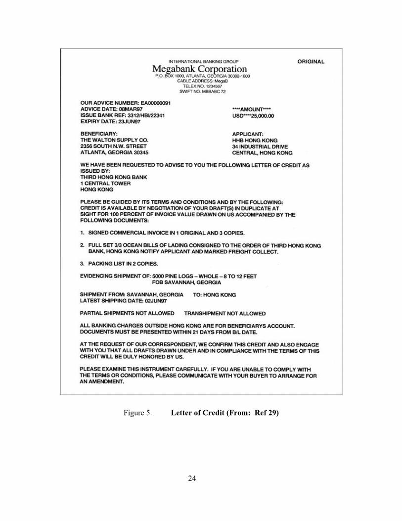
Figure 5. Letter of Credit (From: Ref 29)
24

E. DEFEATING TRACKING SYSTEMS AND E-SEALS
1. GPS
At the heart of the tracking system lays the positional data provided by GPS.
Without GPS the tracking system cannot perform its function. GPS has been found to be
very susceptible to jamming and spoofing. Spoofing is the ability of intercepting data
and sending false data to a recipient to produce misleading information. The John A.
Volpe National Transportation Systems Center published a report stating, “A 1 Watt
GPS-Like signal can prevent C/A code acquisition to more than 620 miles” [Ref 30].
C/A, course acquisition code, is the signal used by the civilian sector.
A spoofing experiment run by John S. Warner and Roger G. Johnston at the Los
Alamos National Laboratory demonstrated how easy it would be to spoof the GPS signal.
By using a modified GPS simulator, breaking the original signal to the GPS receiver with
a GPS jammer, and inserting the GPS signal from the simulator, the scientists were able
to submit false data to the receiver, which would be passed on to an unsuspecting service
provider or customer. The benefit of spoofing the GPS signal makes it easy for criminal
or terrorist organizations to “highjack” a container, truck, or railcar without bringing any
attention to the new course in which the vessel or container would be directed by its new
owner.
During the experiment, the scientists used two stationary trucks with one mounted
with a GPS receiver and the other acting as the attacker with the GPS simulator. After
the original GPS signal from the satellites was broken, a signal from the GPS simulator
was introduced to the receiver. The scientists noted that the spoofing signal could be
maintained up to 30 feet from the receiver, however, initial introduction of the simulated
signal had to be done within close range for 15 seconds to 3 minutes. After establishing
contact with the receiver the attacker could then move out to a maximum distance of 30
feet.
The GPS receivers attacked during the experiment were the handheld receivers
Delorme Earthmate and Magellan Meridian. These receivers may or may not contain the
same circuitry as the receivers used on cargo containers. Also, the scientists noted that
obtaining a GPS simulator was relatively easy. The units could be bought or rented at
reasonable prices. In addition, the units could be homemade using data from the Internet.
25

Lastly, the scientists believe that GPS spoofing could be countered by improving
the accuracy of the clocks within the GPS receivers. The scientists suggest improved
accuracy would not allow the clock error and drift to be exploited. Furthermore, the
scientists believe that if a timestamp was added to the transmission of the signal from the
GPS receiver that spoofing could be detected.
To obtain a copy of this report entitled, “A Simple Demonstration that Global
Positioning System (GPS) is Vulnerable to Spoofing”, the interested reader may contact
Dr. Warner via email at [email protected] [Ref 31].
2. Circumventing or Defeating E-Seals or Tracking Tags
Los Alamos National Labs Vulnerability Assessment Team (VAT) has declared,
“All of these seals, at least in the way they are conventionally used, can be defeated
quickly using only low-tech methods, tools, and supplies available to almost anyone at
low cost” [Ref 32]. This national lab has tested “tamper-indicating seals” for the last 12
years. This section of the paper will discuss the methods which may be used to
circumvent or defeat the security of an e-seal.
One of the problems that may exist for containers equipped with e-seals or tags
placed on container ships is the placement of the container itself on the ship. Containers
can be buried deep beneath the upper decks of a container ship. The burying of the
container may mean that the signal from the e-seal or tag is buried and unable to
communicate with a satellite. This may be overcome by developing an antenna system to
be coupled with the ship’s existing communication system so that the e-seal or tag signal
can be routed above decks and transmitted to the satellite.
A more intentional method of circumventing the function of an e-seal is to cut a
hole in the container or remove the doors of the container from the hinges without
disturbing the seal. Since most e-seals focus on deterring an individual from opening the
doors by sounding an alarm if tampered with, the thief might find a way to go around the
e-seals. Most e-seals are not capable of detecting other points of entry into a container
other than the door entrance.
26
Furthermore, if a thief does not care about his or her intrusion being detected after
the fact, the thief may defeat the seal by destroying it or using electronic jamming to
eliminate the alarm and/or keeping the seal to prevent an investigation from determining

when the break-in occurred. E-seals are often designed to indicate when and where they
were tampered with especially if they do not possess an alarm mechanism. Also, the
perpetrator may remove a tag and place it on another container depending on how secure
the tag is to the original host [Ref 31].
The VAT indicates education of e-seal use and vulnerabilities associated with
particular e-seals and tags is badly needed. Normally e-seal installers and inspectors are
not well trained on the vulnerabilities of e-seals and tags. In addition, vendors and
manufacturers make unreasonable claims about the products they provide. The lack of
education and overstatement of product capability aid sophisticated criminal and terrorist
organizations in exploiting the e-seal and tracking tags [Ref 31].
3. Automated Information Systems
All of the information provided by a tracking system is usually delivered from the
provider via the Internet to the customer. Since the provider is connected to the Internet
the data provided are susceptible to all of the computer and network security
vulnerabilities associated with the Internet. If a provider does not have information
assurance for the company’s network then the provider may be providing false data
injected by hackers working on behalf of a criminal or terrorist organization. Even
though a company has an outstanding information assurance program, if the program is
not extended to the customer an attacker could spoof the customer. Although the
company is sending good data the customer is getting altered data from an attacker,
which is intercepting the good data and resending bad without the company or customer
knowing.
F. SUMMARY Orbcomm, Argos, and Inmarsat satellite communication systems have been
evolving their services over the years and may find that demand for their tracking
services will increase as prices drop and the shipping and manufacturing industries try to
secure the global supply chain from manufacturer to retail. RFID and e-seal technology
will play a significant role in local tracking within a terminal yard and provide security
throughout the cargo containers transit. All of these technologies together, along with the
paper work exchanged to establish payment and a description of the goods being shipped
create an environment that can be examined by organizations of Homeland Security for 27

wrong doing or possible intelligence gathering. In addition, one should not be pulled in
by a false sense of security because there are vulnerabilities which limit the tracking and
security functions provided by GPS, e-seals, and RFID tags.
28

III. TRACKING SYSTEMS FOR SHIPS AND AIRCRAFT
A. SATELLITE SYSTEMS
1. Inmarsat
Inmarsat’s satellite capabilities were developed for ship management and distress
and safety applications. To provide these services Inmarsat has produced the Inmarsat-C
terminal, a two-way data communications device, which is used on road vehicles, trains,
fishing and merchant vessels and in aviation platforms. Once the Inmarsat-C is
operational it transmits to the satellites at frequencies between 1626.5-1645.5 MHz and
receives between 1530-1545 MHz.
Messages can be sent either to or from the terminal. Messages can be no bigger
than 32 kbytes. Messages are packetized upon transmission and reassembled at the Land
Earth Station, where they are sent to the customer via the respective countries
telecommunication system, telex, Internet, or telephone. Furthermore, Inmarsat-C
possesses the capability to be polled. Polling allows the customer base station to query
the Inmarsat-C terminal which causes information to be automatically transmitted back to
the customer. For instance, if a shipping company wanted to know where its vessel was
the company would send a signal from its base station to interrogate the Inmarsat-C
terminal for position data.
The Inmarsat-C terminal can be incorporated with the vessel’s existing navigation
systems, such as GPS or Loran-C receivers, to provide position reporting. In addition,
the terminal is integrated with the Global Maritime Distress and Safety System
(GMDSS). With the touch of a button on a Digital Selective Calling (DSC) radio, a
distress signal containing the name of the ship, the position, and nature of the distress is
sent to other ships, shore stations, and rescue organizations every four and a half minutes.
The signal travels via satellite, Inmarsat, VHF radio channel 70, HF and MF radio
terminals. The International Maritime Organization requires ships over 300 gross tons to
install Inmarsat-C terminals with the GMDSS [Ref 32].
GMDSS is composed of the Digital Selective Calling (DSC) radio, Navigational
Telex (Navtex) weather and navigation information dissemination system, and Inmarsat.
29

See Section D of this chapter for detail on DSC. Navtex is a digital broadcast of weather
forecasts, severe weather warnings, and navigational hazards. The broadcast is
transmitted at 424 and 518 KHz by coastal stations [Ref 33].
Also, Inmarsat-C terminals are capable of sending and receiving e-mail. This
capability largely depends on whether the service provider offers the service. Inmarsat-C
terminals are assigned with a nine-digit identifier called the terminal ID or Inmarsat
Mobile Number (IMN). The IMN allows the terminal to a have a “virtual email address”
when coupled with the domain name of the service provider. The format would be
IMN@domain name. Example of a domain name would be Comsat.com, thus,
[email protected] would be the e-mail address for an Inmarsat-C terminal. The
vessel’s email address and destination address are put in the body of the message. The
addresses are later extracted from the body and forwarded to the recipient via the
Internet. Because data are transmitted over the satellites Inmarsat charges a fee which is
paid via the vessel or terrestrial sender. The charges only apply when data are sent over
the satellites. Service providers that provide e-mail via Inmarsat-C are Comsat, EIK
Global Communications, France Telecom, Station 12, Stratos, T-Mobil, Telstra, and
Telia Mobile [Ref 33].
2. Iridium
Iridium, an Arlington, VA, based company, is composed of 66 low-earth orbiting
satellites which provide coverage over the entire world with the exceptions of Hungary,
Poland, N. Korea, and N. Sri Lanka. Iridium phone calls are not allowed to connect over
these countries’ local telephone systems. The satellites have the capability to cross-link
or relay information amongst them. Crossing-linking also means that the satellite which
received the initial data does not need a gateway to be in the satellite’s footprint which
contributes to fewer outages and relies less on landline networks. Satellite-to-satellite
communications are transmitted at 23.18 – 23.38 GHz [Ref 34].
Services provided by Iridium include data, short burst data, short message service,
voice and paging. Iridium provides services to the marine industry through a two way
voice and data terminal called SkyConnect Marine. Service partner SkyConnect LLC
from Takoma Park, MD, markets the unit and the unit is produced by Icarus Instruments,
30

a Herndon, VA, based company. The terminal can be a dedicated handset for use on the
bridge or multiple phones can share the dial tone. In addition, computers can be
connected to the terminal to access the Internet and send email.
SkyConnect Marine provides communication services only; however, NAL
Research Corporation based in Manassas, VA, provides a product called the 9522 L-Band
Transceiver with GPS. This unit provides position, velocity, and time in addition to the
other services previously mentioned. The terminals transmit and receive communications
at 1616 – 1626.5 MHz [Ref 35].
Iridium’s service partners also provide communication devices for aircraft. Icarus
Instruments also produces the SkyConnect Executive cordless handset. This device is a
satellite phone, which can be used in the cabin of a turbine or turbo-prop aircraft. The
unit is not compatible with GPS because GPS has not been approved for air navigation
purposes. This holds true for other Iridium compatible aircraft communication devices
produced by Iridium service partners Honeywell, Intcomqrp, and BlueSkyNetwork [Ref
35].
3. Eutelsat
Eutelsat is a Paris, France, based company, providing service fleet management
and communication services for the maritime community. The solutions for these
services are titled EutelTRACS and Emsat.
Emsat is predominantly a communication suite for vessels to communicate at sea.
The system provides mobile telephony and data services, SMS and positioning data. The
system is composed of a small central unit with fax, computer, and sensor ports. There is
a mobile handset with screen and an antenna. A GPS card is integrated into the system to
provide positioning data. Emsat transmissions are relayed via an Inmarsat satellite located
at 25.15 degrees East. The gateway for this system is located in Lario, Italy, and
managed by Telespazio. Through this gateway customer’s information is routed to
Public Switched Telephone Network. See Appendix A for communication frequencies
associated with Inmarsat satellites, and see Appendix B for a list of Eutelsat service
providers that offer Emsat or similar solutions.
31

EutelTRACS is a joint project between EutelSat and Qualcomm Incorporated to
bring efficient fleet management solution to maritime industry. EutelTRACS is
supported by two Eutelsat satellites. These satellites are called SESAT and W3, which
are located at 36 degrees East and 7 degrees West. Coverage is provided over Europe,
the Atlantic Islands, North Africa, Middle East and Central Asia, and steerable coverage
exists over the Aegean region and India. The gateway for this system is located near
Paris. The uplink and downlink for the terminals are described in Appendix A.
The EutelTRACS terminal consists of a keyboard, liquid crystal display and base
station. The unit can be connected to temperature sensors, leak and impact detectors via
a RS232 interface connection. Thus, this system could be used for monitoring cargo
containers as well. Software used to manage the link between the customer’s information
system and EutelTRACS Network Management Center is called QTRACS. This
software manages the dispatching, messaging, positioning and mapping capabilities. The
software can be run on personal computers, IBM AS/400 and System/36 midrange
systems, mainframes, and UNIX systems [Ref 36].
4. Globalstar
Globalstar, a San Jose, CA, based company, provides 48 LEO satellites covering
the earth from 70 degrees North to 70 degrees South for satellite phone communications.
The ground segment of the system is made up of gateways, a Ground Operations Control
Center (GOCC), Satellite Operations Control Center (SOCC), and Globalstar Data
Network (GDN).
Through the gateways, transmissions are sent from satellites to the customer. The
gateways are connected to local PSTN or public land mobile networks (PLMN) via T1
lines. Gateways are owned and managed by Globalstar service providers and are
responsible for servicing their countries and other nations depending on the geographical
location. The GOCC plans and controls the gateway terminals use of the satellites and
coordinates with the SOCC. The SOCC tracks satellites, controls their orbits, and
provides telemetry and command services. The GDN provides the connectivity amongst
all of the elements previously mentioned [Refs 37 and 38].
32

The company’s original mandate is to provide handheld satellite phone service
around the world. However, in recent years the company started to provide Internet and
private data network connectivity, position location, SMS, and call forwarding.
Globalstar does not advertise any of its services as being vessel-monitoring solutions or
asset management tracking services; however, they do provide the solutions needed for
aircraft and commercial and cargo ships to communicate position and other data while
deployed.
Communication devices made for ships and aircraft uplink to the satellites at 1610
– 1625.5 MHz and downlinks at 2483.5 – 2500 MHz. The coverage only extends a little
beyond 200 miles from the coastal areas around the world. This means that entire oceans
are not covered, causing dropped calls in those areas. Figure 6 depicts the coverage
provided by Globalstar. Within Figure 6 note that the orange color denotes the primary
service area, the yellow color indicates extended service area low signal strength and the
purple color represents areas with intermittent signal strength [Ref 34].
Although, Globalstar does not offer complete global coverage, the system assures
connectivity in the primary service areas through a process called “path diversity”. This
process enables two or more satellites that cast a footprint on the user to capture and
transmit the call simultaneously. If a user moves out of the satellite footprint, the call is
able to continue through another satellite without loss or disruption of the call [Ref 39].
Figure 6. Globalstar Coverage (From: Ref 39)
33

Position location is provided by the Globalstar constellation rather via the GPS
satellite system. The satellites calculate position using radio frequency (RF) time
difference of arrival (TDOA), frequency difference of arrival, angle of arrival or a
combination of the geolocation methodologies. Accuracy of the positions is up to 10 km.
Incidentally, this type of positional technology is similar to Radio Determination
Satellite Service (RDSS) created by GEOSTAR in the 1980s and currently owned by
Comtech Mobile Data Corporation (CMDC). RDSS establishes geolocation by radio
frequency TDOA using two or more satellites in geosynchronous orbit. CMDC currently
uses GPS along with the two-way communication capability of RDSS to provide location
data in its movement tracking system service, which is enabled by Inmarsat constellation.
Although GPS technology seems to be the favorite for geolocation, RDSS is worth
investigating. Major Darius M. White, class of 2002 from the Naval Postgraduate School
conducted thesis research on RDSS systems; thus, exploring his thesis would be an
excellent way to find a complete discussion on RDSS and the geolocation methodologies
mentioned previously [Ref 40].
Unlike others in the satellite service industry, Globalstar offers encryption to
secure the customers communications. The encryption algorithm used is either Harris
Citadel CCX or Triple Data Encryption Standard (DES). The encryption key is 128 bits
in length. There are three unit models produced by Qualcomm, Rainbow Mykotronix,
and Copytele Inc. See www.globalstar.com/view_page.jsp?page=encryption for more
information about the encryption units produced by the previously mentioned
manufacturers [Ref 41].
5. Thuraya
Commercial service for the Thuraya system commenced during July 2001.
Thuraya Satellite Telecommunications Company, based in United Arab Emirates, owns
the system. The system is made up of three geostationary satellites located at 44 degrees
East, 28.5 deg East, and 87 degrees East. These locations allow coverage for Western
Europe, Northern Africa, the Middle East, Central Asia and India. Figure 7 provides an
illustration of the Thuraya coverage map.
34

Figure 7. Thuraya Coverage Map (From: Ref 42)
Whether or not Thuraya offers location system solutions for cargo containers,
ships, or aircraft is unclear since its primary purpose is to offer satellite phone capability
throughout the coverage area. However, Thuraya’s handsets contain satellite, GSM, and
GPS technology. Thus, this system could provide customers with tracking capability but
without the automation provided by other systems mentioned earlier. This is definitely a
system that could cater to private individuals, small businesses, and criminal or terrorist
syndicates. These phones transmit and receive at 1626.5 –1660.5 MHz and 1525 – 1559
MHz, respectively. The headsets are dual mode, thus they can switch from GSM to the
Thuraya Satellite network when out of range of GSM cell towers [Refs 34 and 43].
6. New ICO
New ICO is a London, UK, based company that offers global coverage for
messaging, data transfer, telephone and Internet connectivity via handheld devices. To
launch this service the company will operate 10 satellites with 2 spares at MEO with
inclinations at 45 and 135 degrees. There will be 5 active satellites per orbital plane. The
ground segment of the system will consist of 12 earth stations or Satellite Access Nodes
(SAN) located throughout the world. Using the company’s high-bandwidth global
Internet Protocol network called ICONET the satellites will be able to communicate with
the SAN [Ref 44]. 35

Like the Thuraya system, the handsets will be dual mode capable. The handsets
will automatically switch from GSM network to the New ICO network depending on the
signal strength with a GSM tower or users can manually switch between networks. The
handsets will uplink at 2165 – 2200 MHz and downlink at 1990 – 2025 MHz.
Furthermore, the National Rural Telecommunications Cooperative (NRTC) reports that
New ICO proposed to the Federal Communication Commission to authorize the use of
satellite frequencies on the ground for all Mobile Satellite Service (MSS) providers. By
transmitting satellite frequencies on the ground amongst a MSS provider’s earth stations,
the user would not have to be in view of the satellite to connect to the MSS providers
network. Whether the FCC has ruled on this proposal is uncertain [Ref 45].
7. Ellipso
Satellites communication providers will continue to grow in numbers and expand
their services. New systems such as Ellipso, a Washington DC based company, which
comes online in the next couple of years will expand their services from personal
communications to asset management tracking to expand their market audience and
profitability.
Ellipso’s handsets and terminals are unique in the fact that they are capable of
providing global positioning data and look very similar to mobile cell phones carried
today. In addition, the handsets can act as modems for accessing the Internet. The
phones are dual mode, which allows them to access cellular phone networks and the
Ellipso network. Ellipso’s terminals will operate using second generation (2G) and third
generation (3G) technologies. The 2G terminals will transmit at 2165-2200 MHz and
receive at 1990-2025 MHz. The 3G terminals will transmit at 1610-1621.5 MHz and
receive at 2483.5-2500 MHz.
The difference between 2G and 3G technologies in the Ellipso network lies in the
bandwidth. The 3G technology uses wideband Code Division Multiple Access (CDMA)
and 2G is straight CDMA. Wideband indicates that the frequency band is four times
larger than the 2 GHz band used in 2G. This wider frequency band will allow more users
to carry on simultaneous conversations.
36
Ellipso’s satellite constellation will consist of four orbital planes covering the
world from 50 degrees South and upward. There will be two elliptical orbits consisting

of 5 birds each inclined at 116 degrees. The apogees are 7605 km and perigees are 633
km and the orbital period is 3 hours. There will be two circular orbits at 8050 km
consisting of four and three birds inclined at 50 degrees South and 50 degrees North.
The Ellipso system will start with 12 gateways and be connected to the local
telecommunication networks using an Internet protocol to talk on wireless or wireline
networks. The gateways are also designed to be the workhorses of the system leaving the
satellites to relay data only. The gateways will conduct hand-offs, signal modulation,
multiplexing and satellite tracking [Ref 46].
B. HUMAN AGENTS
Lloyd’s Marine Intelligence Unit (LMIU) a London, UK, based company has
established a network of human agents throughout 2000 ports around the world to
provide information on the movement of vessels. The network is comprised of 400
principal agents and supported by what the company calls subagents. The agents gather
their intelligence from Port Authorities, coast guards, pilots, customs, insurers, news
agencies, and other trusted sources.
Information provided by the agents includes owner, change of owner, flag
changes, operator, casualty reports, types of communications systems aboard the vessel,
Inmarsat communication identification number, origin and destination of the vessel,
characteristics of vessels such as engine type, fuel type, position and size of cargo hold,
type of lifting equipment on board and more. A complete list of items gathered by LMIU
agents can be found at www.lloydsmiu.com.
All the data are put into a database. LMIU boasts that the company has
movement and ownership data since 1976 and casualty data available since 1990. LMIU
allows customers to access the data via the Internet, CD-rom, or hard copy. For instance,
LMIU’s Vessel Tracker service provides arrived and sailed dates, expected sailing date,
next port of call, and estimated time of arrival. For more money the service will provide
name, flag and ownership changes. This service is fed directly by the agent network.
This service may be provided to the customer via email or LMIU website [Ref 47].
C. AUTOMATIC IDENTIFICATION SYSTEM (AIS) AIS is not a global tracking system, but serves more as a control and local
tracking technology for ships approaching port. AIS is a broadcast communication
37

system mandated by the International Maritime Organization (IMO) for the safety of
mariners. The purpose of the system is to provide collision avoidance while underway,
notice of arrival to ports, and traffic management coming into ports. By using VHF
transmitters, two VHF Time Division Multiple Access receivers, one VHF Digital
Selective Calling (DSC) receiver, GPS and DGPS receivers and a link to shipboard
display and sensor systems information such as the ship position, course and speed, rate
of turn, angle of heel, pitch and roll, Maritime Mobile Service Identifier (MMSI), IMO
number, radio call sign, name of ship, dimensions of ship, draught of ship and more are
passed to other AIS equipped ships or shore stations. Using this information ships and
shore stations can immediately identify an approaching ship and provide short messages
containing warnings or navigational hazards via email or radio [Ref 48].
AIS will be fitted to all ships as mandated by IMO’s Maritime Safety Committee
in Chapter V, Regulation 19.2.4 which applies to all ships of 300 gross tons and upwards
engaged on international waters voyages and cargo ships of 500 gross tons and upwards
engaged on international voyages and passenger ships irrespective of size. Further details
on this regulation concerning the dates in which the rules will apply to other vessels can
be found at www.navcen.uscg.gov/enav/ais/AIS_carriage_reqmts.htm [Ref 48].
In addition, the Maritime Transportation Security Act (MTSA) orders AIS on all
commercial vessels of at least 65 feet in length, certain passenger vessels (as determined
by the Secretary), and towing vessels over 8 meters and 600 hp; on all navigable waters
of the United States. The MTSA also grants the Secretary authority to expand carriage to
any other vessel it deems necessary for safe navigation, to issue exemptions or waivers
should it find that AIS or other navigation requirements are not necessary for the safe
navigation of a vessel or on a waterway, and, directs the Secretary to prescribe
regulations implementing these provisions. Secretary refers to the Secretary of the
Department of Homeland Security in which the Coast Guard operates [Ref 48].
There are five AIS types; however, Class A and Class B models are only relevant
for this discussion since the interest is in tracking ships. Class A is for the vessels
mention above in IMO regulation. Class B is for vessels that do not meet the
requirements for Class A. Class B systems do not transmit vessel’s IMO number or call
sign, estimated time of arrival or destination, rate of turn, static draught and navigational
38

status. Other AIS systems are located on search and rescue aircraft, shore stations
providing location of navigational aids and shore stations providing text messages.
The system transmits in the VHF band thus range of the signal is nominally good
out to 20 nautical miles. Frequencies used by the system are 161.975 and 162.025 MHz.
If repeaters are used the signal can be extended farther. Also, there is movement afoot to
have the signal relayed over Inmarsat satellites since ships of 300 gross tons and above
are required to be fitted with Inmarsat-C for GMDSS, which was mentioned earlier in
this document [Ref 48].
D. DIGITAL SELECTIVE SERVICE (DSC)
DSC is used with both AIS and GMDSS. DSC is digital technology incorporated
in the latest VHF, MF, and HF marine radios. Using what some mariners call the
“mayday button”, a preformatted distress message is transmitted in digital form. The
message will contain the MMSI and geolocation if integrated with GPS. DSC also
allows a vessel to selectively call a specific vessel without other vessels or stations in the
area receiving the message. Thus, the call-up of a vessel on channel 16 and switching to
a more private channel is not needed. DSC is set to channel 70 on VHF radios [Ref 49].
E. SUMMARY
All of the satellite systems mentioned above are communication systems that
offer geolocation service; however, they target different audiences for their products. In
general, Inmarsat, Iridium, Eutelsat, and Globalstar provide service for shipboard and
aviation use. Thuraya, New ICO, and Ellipso provide personal communication for those
in areas where conventional phone service is not available. In addition, the personal
phones provided for each of these systems could be used on established cellular networks
due to the dual modality designed into the handsets.
Because these units do offer global communication for personal use, terrorist and
criminal organizations are probably taking full advantage of this capability to manage
their enterprises. Elements of Homeland Security should explore these systems to gleam
any information that may provide indications and warnings of terrorist and criminal
activity. In addition, if AIS is transmitted over Inmarsat, this information and that data
produced by LMIU should be leveraged to diminish the threat against the sea lanes of
commerce.
39

THIS PAGE INTENTIONALLY LEFT BLANK
40

IV. METHODS FOR TRACKING UNIQUE ITEMS
A. DIAMONDS
1. Illicit Trade of Diamonds
Diamonds are a form of currency that can be moved in a moment’s notice and
with little trouble. Imagine carrying ten million dollars in your pocket without any
suspicion. Due to their ease of movement, they are very attractive to criminal and
terrorist organizations. They are used to pay debts, pay bribes, and buy arms due to the
ease of their liquidation. To thwart the illicit trade of diamonds often called “Blood
Diamonds” or “Conflict Diamonds” the international community has sought a process,
which depends on a chain of certificates to accompany the shipment of raw diamonds.
The world will depend on these chains of certificates called the Kimberly process to
enforce accountability and deterrence in the illegal trade of diamonds.
Before discussing the Kimberly process, take a look at the world diamond mining
industry in Figure 8. Most of the world’s diamond deposits are in Africa, Australia,
Canada, and Russia. Major diamond trade takes place in Antwerp, Tel Aviv, New York
and Mumbai. The hot spot for diamonds is in the African region due to civil wars taking
place in countries such as Sierra Leone, Angola, and the Democratic Republic of the
Congo. In these regions the sale of diamonds is used to finance the internal conflicts.
41

Figure 8. Snap Shot of the World Diamond Industry (From: Ref 50)
In addition, terrorists are able to cash in on the instability of the regions because
their movements go largely unnoticed, and they are able to launder money via buying
diamonds. Monrovia, Liberia, has reportedly become the place to launder money using
diamonds. To make the transaction, one would find a willing Monrovian diamond
salesman, offer to buy the diamonds a little over market value to make the transaction
appealing to the salesman, travel to either Switzerland, the United States, or Antwerp,
Belgium and sell the diamonds below market value to redeem the cash quickly [Ref 50].
2. Tracing Rough Diamonds
In illicit transactions such as this, rough diamonds are probably bartered. Rough
diamonds are virtually untraceable. However, the BBC reported early this year that
Belgian scientists have devised a way of determining the origin of individual diamonds.
Scientists have developed a technique, which can provide a chemical fingerprint of a
diamond that will reveal where the diamond was mined. The technique consists of
drilling a microscopic hole into a diamond and extracting a sample. Using chemical
analysis techniques the sample is compared to other samples to determine where the
diamond originated. The technique is still being perfected and scientists will have to
gather chemical composition fingerprints from diamond mines around the world to have a
basis to compare rough diamonds [Ref 51].
42

3. Tracing Polished Diamonds
Polished diamonds that are made ready for retail sale are often engraved with a
serial number using a laser or an ionic beam. The serial number is usually placed along
the girdle of the diamond. These high-tech engravings make polished diamonds easier to
track. Figure 9 reveals Canadian diamond companies fingerprinting techniques to allow
their diamonds to be tracked.
Figure 9. Diamond Fingerprinting (From: Refs 52 and 53)
4. Kimberly Process
The Kimberly Process also ensures that polished diamonds do not come from
conflict diamonds due to the controlled process in which rough diamonds are handled.
The Kimberly Process Certification Scheme (KPCS) was born May 2000 in Kimberly,
South Africa in response to the threat of conflict diamonds illicit trade undermining the
legitimate diamond market. The United Nations General Assembly Resolution 55/56
urged the international community to provide a solution to curb the trade of conflict
diamonds and KPCS was the answer from over 50 nations, which attended the
conference.
KPCS requires that a nation involved in the trade of rough diamonds provide a
certificate to accompany the shipment of the rough diamonds and the container to be
sealed. The certificate will travel with the diamonds all the way to the retail buyer. In
addition, a confirmation receipt is sent to the originating exporting authority. The
43

country from whose territory a shipment of rough diamonds is leaving and possesses the
authority to validate the Kimberly Process Certificate designates the exporting authority
[Ref 54].
Nations participating in the KPCS are responsible for developing their
certificates; however, they must contain specific elements to meet the minimum
requirements set by the Kimberly Process. Those standards are as follows:
- Each Certificate should bear the title “Kimberley Process Certificate” and the following statement:
- “The rough diamonds in this shipment have been handled in accordance with the provisions of the Kimberley Process Certification Scheme for rough diamonds”.
- Certificates may be issued in any language, provided that an English translation is incorporated;
- Unique numbering with the Alpha 2 country code, according to ISO 3166-1 - Tamper and forgery resistant - Date of issuance - Date of expiry - Issuing authority - Identification of exporter and importer - Carat weight/mass; Value in US$ - Number of parcels in shipment - Relevant Harmonised Commodity Description and Coding System - Validation of Certificate by the Exporting Authority Optional Elements - A Certificate may include the following optional features: - Characteristics of a Certificate (for example as to form, additional data or
security elements); - Quality characteristics of the rough diamonds in the shipment; - A recommended import confirmation part should have the following elements: - Country of destination; - Identification of importer; - Carat/weight and value in US$; - Relevant Harmonised Commodity Description and Coding System; - Date of receipt by importing Authority; - Authentication by Importing Authority [Ref 55].
Although the KPCS has the best intentions, it will only be as good as the
earnestness and commitment forged by each of the nations participating in the process.
44

B. INTERNATIONAL BANK CHECKS
There is no standard process in which foreign checks are handled by financial
institutions. The following is an email from a colleague describing how his institution
handled foreign transactions. Mr. Turner worked in the banking industry for nine years
and held the position for Regional Vice President before embarking on a new career.
Back when I used to negotiate checks drawn on foreign banks the procedure would be to provide our client a voucher for acceptance of the check drawn on the foreign bank. Then we would prepare an international draft requesting that the check be converted to one drawn on a US dollar account with a bank that uses the US Federal Reserve as a clearinghouse. We would then wait on a physical check to credit our client's account. In some cases the foreign bank would wire transfer the funds to our client's account. This scenario was especially true for banks in developing or third world countries, or those with unstable governments. Another scenario is that the check you were presented is actually drawn on a US dollar account with an American bank that the foreign bank uses for its dollar accounts. In this case your bank would simply take the check as deposit and credit your account as it would with any other check drawn on a US bank [Ref 56].
This process may be entirely different at other institutions, but they may use
common conduits to communicate the transaction of a foreign check. Some of the
communication systems used by banks are Telex and SWIFTnet.
1. Telex
Telex stands for teleprinter exchange. From the 1920’s until the 1980’s, a
network of mechanical and electronic teleprinters and telephone switching centers made
up the Telex system. The system operates with the international telegraph alphabet Nr. 2
and at a throughput speed of 50 baud. Telex allows real-time two-way text
communication between two users. Terminals used by each user display what is being
written by the sender and receiver. Industries that use the system are largely the financial
and shipping sectors. In the shipping industry Inmarsat-B terminals deliver Telex from
ships to Inmarsat LES via satellite. The LES has connectivity with the Telex network.
45

These industries use Telex because the system provides delivery receipt of a
message and requires authentication between sender and recipient. Due to this capability,
Telex was granted global document legal status. Documents sent via telex are considered
legally binding. Major banks do not use the Telex system anymore, but the system is still
used in developing countries [Refs 57 and 58].
Today, instead of using outdated teleprinter terminals Telex is accessed with
Personal Computers (PC) running Telex software or through an internet/Telex gateway.
Using Telex software such as TMData Services’ PCTelex on an IBM compatible PC
equipped with a Hayes modem, a user can dial into the TM Telex Network through a
PSTN. The software emulates the functionality of a Telex terminal to be able to send and
receive telex messages [Ref 58].
Telex accessed via an internet/Telex gateway may or may not require the addition
of software. A company called Plain Sailing based in the UK offers Telex services using
existing email. Email is prepared as usual; however, the recipient’s address is unique.
For instance, [email protected] indicates that there is a telex message
being sent (TX), to UK (country code is 51) and Telex number is 290899. The message
is then delivered via the Internet to the TelexByNet router, passed to the Telex gateway
where the message is entered on the Telex system and reports from the Telex gateway are
sent to the Telex delivery reporting system, and reports are sent to the originator. Reports
contain delivery confirmation, acknowledgement from the recipient that the message was
received; duration of the transaction, and date and time Telex was received [Ref 59].
This method is not real-time; however, Plain Sailing does offer real-time service
through a package called RealTelex. This package requires software that emulates a
Telex terminal. Connecting through the Internet to the RealTelex router, messages are
sent to the Telex gateway and directly to the recipient’s Telex machine. The RealTelex
software provides the functionality of Plain Sailing’s Telex delivery reporting system.
The software will log incoming and outgoing messages, as well [Ref 59].
Until 1973 banks, communicated with Telex. Since this time, Telex was
automated by the banking industry through an industry-owned cooperative called the
Society for Worldwide Interbank Financial Telecommunication (SWIFT). Today SWIFT
46

is composed of 7500 financial institutions from 199 countries that provides the
communication network for secure transactions between the institutions. In 1977, the
company introduced the Financial Information Network (FIN). FIN is a store and
forward financial messaging service that runs on the X.25 protocol.
X.25 is a packet switching protocol designed for sending data over a wide area
network. The protocol allows users to establish virtual paths between them. A subscriber
of the network will call another subscriber. As the call is placed, switches and circuits
are established to create the dedicated path. X.25 does not have Internet Protocol (IP)
addressing. X.25 addresses are noted as called address and calling address. The source
of the call must provide its address and the address of the subscriber being called to
establish a virtual calling session [Ref 60].
2. SWIFTnet
In addition, X.25 provides error detection and correction due to slow throughput
speeds. Coupled with encryption X.25 provided a suitable communication solution for
banks considering the importance of their communication transactions. Although FIN is
still being used today, the system is being replaced with SWIFTnet FIN. SWIFTnet FIN
provides secure real-time and store-and-forward messaging file transfer and browsing
capability. SWIFTnet FIN runs on the IP protocol and encrypts traffic with Public Key
Infrastructure (PKI) technology and uses secure IP protocol between networks. Secure IP
commonly called IPsec uses router gateways to provide an encrypted Virtual Private
Network (VPN). SWIFT is the certificate authority, registration authority, and certificate
directory for its PKI. Using proprietary software, SWIFTnet Link and SWIFTAlliance
interface products, SWIFT projects to have its members connected to SWIFTnet by the
end of 2004 [Ref 61].
C. SUMMARY SWIFTnet handles large transactions such as foreign exchange payments,
securities transaction and other large transactions between financial institutions. Thus,
due to the continuing use of Telex in Third World countries and the ability of Inmarsat-B
terminals to communicate Telex messages from sea to shore, the Telex system may be
47

used in communication efforts by terrorist or their financial transaction may be sent via
Telex since this system is sometimes the premiere communication standard in a
developing nation.
Furthermore, if the Belgian scientists are able to perfect a technique that can
match a diamond to its origin this may give the Kimberly Process real influence in
curtailing illegal diamond trading. Customs agents or other authorities would be able to
determine if the Kimberly Certificate was valid by comparing the scientific origins of the
diamonds to those origins alleged on the certificate. This type of validation process
would eventually make diamond trading for terrorist and criminal organizations an
uninviting venture.
48

V. CONCLUSION
A. APPLICATIONS
1. Maritime Tracking System
There have been discussions in the US government for creating a maritime
tracking system for ships, which approach the coastal waters of the United States. The
Chief of Naval Operations has exclaimed,
In conducting homeland defense, forward deployed naval forces will network with other assets of the Navy and the Coast Guard, as well as the intelligence agencies to identify, track and intercept threats long before they threaten this nation.
I said it before and I’ll say it again today, I’m convinced we need a NORAD for maritime forces. The effect of these operations will extend the security of the United States far seaward, taking advantage of the time and space purchased by forward deployed assets to protect the U. S. from impending threats [Ref 62].
This thesis contributes to a possible national maritime tracking effort by providing
information on tracking systems used by commercial sectors to track ships and aircraft
that could be monitored by Homeland Security and Defense organizations for terrorist
activity.
As described in Chapter III, the Automated Identification System (AIS) could be
transmitted via Inmarsat satellites. Instead of having the AIS signal transmitted 96 hours
before reaching US coastal waters, transmissions could be sent via Inmarsat and relayed
to maritime watch centers around the world whenever vessels set sail. Foreign and US
Coast Guards would be able to track vessels from port-to-port around the globe and share
their data on suspicious ships. The Maritime Security Act supports this general concept.
However, Maritime Information Service of North America (MISNA) proposes to
take advantage of the GMDSS and Inmarsat combination as opposed to AIS because
GMDSS is a more established system. GMDSS is currently used for emergency
situations, but MISNA recommends having authorized shore stations polling the system
for positional data and having that information relayed to a central watch floor [Refs 62
and 63]. Even though each system currently provides a unique service both can be
49

adapted to broadcast geolocational data of ships around the world over a satellite
network. Monitoring such a network will help to mitigate terrorist activity upon the lanes
of commerce.
2. Telex Coverage
In addition, this thesis raises the concern that terrorists may be using the Telex
system to communicate within their organizations due to the geographical locations in
which they operate. Terrorists are often operating in developing countries or third world
countries to keep a low profile. These countries may not have established cellular
networks or access to the Internet. However, a Telex system may be operational. In
addition to possible terrorists’ communiqués passing over these networks, terrorist
financial transactions may be passing over the Telex system. Telex was originally
developed to support banking transactions, and some poor countries may still be using
this system in their financial institutions. If the Telex system is not being monitored
Homeland Security and Defense Organizations should investigate these systems.
3. Pushing E-Seals and RFID Development
Lastly, this thesis points out the weaknesses associated with e-seals and RFID tag
systems. Knowing these weaknesses will give policy makers within the Homeland
Security Organization the ability to continue a push for the development of better e-seals
and RFID tags. In addition, education on the installation and inspection of these systems
may be brought to the forefront to enhance security not only from the product end but
from the user end, as well.
B. AREAS FOR FURTHER STUDY
1. Relatively New Satellite Systems
There are a number of new satellite systems that have recently come online or will
be coming online in the near future. Globalstar, New ICO, and Ellipso systems meet the
description of being new or relatively new, thus they require a more in-depth
investigation, which may lead to better collection efforts against these communication
systems. In addition, there needs to be a continuing lookout for existing satellite systems
that may initiate the offering of location services in their solution or product line.
Furthermore, satellite systems that provide digital television broadcasting should be 50

explored for tracking capability. In a report written November 2002 by EyeForTransport
called “Cargo Security Overview”, the organization lists the use of digital television
frequencies as an emerging technology for tracking mobile assets. Currently open
sources do not provide any insight into this technology, but it may be on the horizon [Ref
64].
2. More Spoofing Required
The GPS spoofing experiment conducted by Los Almos National Lab was an eye
opener to the vulnerability of the GPS system. Similar experiments aimed at actual GPS
receivers used in tags and e-seals presented in this paper and those in the near future
should be conducted to provide an even more realistic environment. Further exploration
should include the possibility of targeting GPS receivers on ships and planes. Targeting
GPS for ships and planes may stimulate debate for adding protections to the civilian GPS
signal. If success is found in spoofing or jamming the GPS receivers on ships and
aircraft, one must also study the protective measures being taken by the Europeans to
prevent spoofing and jamming against the Galileo project. The Galileo project is being
built for the sole purpose of assuring continuous civilian use and for aviation navigation.
For instance, if foreign aircraft entering European airspace are to use Galileo for air
navigation, what protective measures are the Europeans taking so that the signal cannot
be compromised which may cause an aviation accident?
3. Combination of Satellite and RFID Tracking System
In the near future there may be the possibility of marrying RFID technology with
satellite communication technology. This paper has already mentioned the relationship
that exists between 802.11b, Bluetooth Lite, GSM and satellite technology, which is used
to track containers. However, no company has presented a solution that uses RFID and
satellite technology to provide full-time tracking of a cargo unit. Generally, RFID
technology stops when the container unit is loaded on a vessel and picks up again when
the unit gets to its destination. Thus, there is no tracking provided while the container is
in transit except for maybe the tracking of the vessel.
NASA’s Jet Propulsion Laboratory in Pasadena, CA, proposes the development of
a system that would use an infrared transceiver for local communication and a microwave
51

transceiver for communication over longer distances. To accomplish this proposal, a tag
or transponder would work in unison with what the lab calls a retainer unit. The tag
would have the basic functions of being able to store data, providing self-power and
incorporating GPS. The tag would then be placed into the retainer. Through the retainer,
communication could be done via a satellite, microwave repeaters, infrared, and possibly
with RFID. This design allows for more information to be loaded on a tag and
communicated in local and transient environments [Ref 65].
The problem with developing such a device as proposed by NASA or other
systems like it is maintaining a power source and keeping the cost of the unit down.
After manufacturers are able to manage the power issue more systems will be developed
which are similar in concept proposed by NASA. Thus, the market needs to be
monitored for these new developments.
C. SUMMARY OF WORK The goal of this project was to explore the different tracking technologies used to
trace cargo containers, ships, and aircraft. In addition, an investigation of tracking unique
items such as diamonds and foreign bank checks was conducted to gain some insight on
how the diamond and financial industries could be examined to mitigate criminal and
terrorist exploitation in these areas. This study also alerts organizations in Homeland
Security and Homeland Defense of new communication signals that will be associated
with commercial shipping, which can be scrutinized for evidence of terrorist activity.
Lastly, the vulnerabilities associated with the deployment of GPS, e-seals and tags
were reiterated from the findings conducted by the VAT at Los Alamos National
Laboratories. Although e-seals and tags are developed with the intentions of improving
security, improper use may be undermining their effectiveness. In addition, authorities
should always be mindful that malicious computer attacks could be performed to spoof
the contents of a cargo unit. In other words, what a user sees on the screen may be what
the company intended to ship, but what was actually shipped in the designated cargo
container was something entirely different. The stroke of a few computer keys can
subvert state-of-the-art tracking technology unless a strong information assurance plan is
implemented and executed in concert with the tracking systems.
52

APPENDIX A. SATELLITE CHARACTERISTICS
Description ORBCOMM ARGO INMARSAT GLOBALSTAR IRIDIUM EUTELSAT
Orbit Type LEOPolar Sun Synch,
Circular GEO LEO LEO GEOOrbit Height (Km) 900 850 36000 1400 900 36000Number of Satellites 30 4 to 6 6 to 20 48 (8 spares) 66 3Frequency Uplink (MHz) G-S 148 - 149.9 PTT - S 401.65 T-S 1626.5 - 1646.5 G-S 5091 - 5250 G-S 29.1 - 29.3 GHz 13 - 14.5 GHz
Frequency Downlink (MHz)G-S 137 - 138, 400.05 -
400.15 unknown S-T 1530 - 1545 S-G 6875 - 7055 S-G 19.4 - 19.6 GHz 10.95 - 12.75 GHzMAC Method X.400 unknown FDMA CDMA FDMA/TDMAService Data, GPS and messaging Data, GPS Voice, data, fax, telex Voice, data, fax Voice, Data, FAX, GPS Voice, fax, data, sms, GPS
Coverage Global Global Global Global Global
W & E Europe, Mediterranean, Middle East, and Atlantic Oean
Inclination (degrees) 45 and 135 98.7 0 - 4.2 52 86.4 13.5Website orbcomm.com argosinc.com inmarsat.com globalstar.com iridium.com eutelsat.com
Description NEW ICO THURAYA ELLIPSO EGNOS GalileoOrbit Type MEO GEO Cir Equatorial & Elliptical GEO MEO
Orbit Height (Km) 10000 36000C - 8050, Ellipt A-7605, P-
633 36000 10000Number of Satellites 10 3 17 3 30Frequency Uplink (MHz) S-H 2165-2200 G-S 6425 - 6725 G-S 15400 - 15700 1.6 GHz C and L band Frequency Downlink (MHz) H-S 1990-2025 S-G 3400 - 3625 S-G 6775 - 7075 14 GHz uknownMAC Method TDMA FDMA W-CDMA CDMA CDMAService Voice, data,fax, GPS Voice, data, fax, GPS Voice, data, GPS, Internet GPS GPS
Coverage Global
Western Europe, N. Africa, Middle East, Central Asia, & India 55 degrees South and up Europe Global
Inclination (degrees) 45 6 0 and 116 0 56Website ico.com thuraya.com ellipso.com esa.int esa.int
Satellite Systems
53

THIS PAGE IS INTENTIONALLY LEFT BANK
54

APPENDIX B. VENDOR LIST
Satellite Resellers and Service Providers
1. ORBCOMM RESELLERS
Hansestar OHB Teledata GmbH Universitatsallee 29 28359 Bremen Germany Phone: +49/421/20 20-8 www.hanestar.com ADSI 1031 Bay Blvd. Suite F ChulaVista, CA, 91911 USA Phone: (619) 585-0435 www.satguard.com
OMNITRONIC SA Ing. Norberto Pesce, Director 5501 Godoy Cruz Avda. San Martin Sur 36 Mdza Argentina Phone: +(54) 261-422-0359 www.omnitronic-sa.com SkyTracSystems Ltd. Kathleen Wallace, 201-3590 Airport Road Penticton, British Columbia, V2A 7J6 Canada Phone (250) 492-5363 www.skytrac.ca Telespazio S.p.A. Guglielmo Mazzacano, Via Tiburtina, 965 Rome, 00156 Italy Phone: +(39) 06 4079 3365 www.telespazio.com
55

VEERS Elektronik + Meerestechnik GmbH & Co. KG Stephan Wenzke,Flugplatz Holtenau Sued Eekbrook 15Kiel, Germany, D-24159Europe Phone: +49 (0) 431 / 36 914 36 www.veers-kiel.de XR Communications Brian J Wilson, COO 404-12 High Street E Moose Jaw, Saskatchewan, S6H OB9 Canada Phone: (306) 693-3442 VascoTrack Ltd. Phil Vella, General Manager No. 2 Royal Mews Gadbrook Park Northwich, Cheshire, CW9 7UD UK Phone: +(44) (0) 1606-812-600 www.vascotrack.com 2. INMARSAT SUPPLIERS Arcom Telecom Services & Applications 40 Agiou Konstantinou, Aethrio Centre Maroussi 151 24 Athens Greece Phone: +30 (210) 6107379 DH-Intercom Felix-Wankel-Str 16 Oldenburg D-26125 Germany Phone: +49 (441) 9350320 7E Communications Swan House 203 Swan Road Middlesex TW136LL United Kingdom Phone: +44 (0) 20 8744 8500 www.7E.com
56

Marlink Communications Avenue Guillaume Herinckxlaan 80 Brussels 1180 Belgium Phone: +32 (2) 3717111 www.marlink.com VISTAR 2 Brewer Hunt Way Kanata, ON K2K 2B5 Canada Phone: 1-866-499-6199 www.vistardata.com 3. EUTELSAT SERVICE PROVIDERS Markland Group, Inc 108, Ivan Javakhishvili St Tbilisi 380064 Georgia Phone: +995 77 41 07 50 France Telecom Mobile Satellite Communications 16 Boulevard du Mont d’Est 93192 Noisy-le-Grand Cedex France Phone: +33 1 48 15 73 54 Telespazio Via Tiburtina 965 00156 Rome Italy Phone: +39 06 4079 3778 CTC 31-33, Smolenska St. Kiev 01680 Ukranine Phone: +380 44 490 8128 Applied Satellite Technology Burlingham House Hewett Road Gapton Hall Estate Great Yarmouth
57

Norfolk NR31 ONN United Kingdom Phone: +44 1245 275 581 SATKO Buyukere Cad. No: 121 Ercan Han II-Blok Kat: 4-80300 Gayrettepe Istanbul Turkey Phone: +90 212 212 8200 4. IRIDIUM SATELLITE SERVICE PARTNERS Electronic & Electrical Maintenance Co Shuwaikh-Industrial Area Area 1, Street 12 Block 99 Kuwait Phone: +965 482 0113 www.eemchkuwait.com East Satcom Telecommunications United Emirates Phone: +97114 2211211 European Datacomm NV Heidestraat 257 2070 Zwijndrecht Belgium Phone: +32 3 210 15 10 www.edchq.com Global Plus Limited Allied Building Francis Rachel Street P.O. Box 195 Mahe Seychelles Phone: +27 12 346 1444 www.global-plus.com
58

Xantic P.O. Box 153 Caboolture Qld 4510 Australia Phone: (71) 22432 Telcsc AA www.xantic.net Jembas Assistencia Tecnica Lda Rua Rainha Ginga 190 Luanda Angola Phone: +244 2 320629 www.jembas.com Singapore Telecommunications Ltd. Mobile Satellite Business 15 Hill Street #02-00 Telephone House 1 Singapore 179352 Phone +65 64169333 www.singtel.com 5. GLOBALSTAR REGIONAL PROVIDERS Saudi Globalstar Operations P.O. Box 25916 Riyadh 11476 Saudi Arabia Phone: 966 1 474-8848 Globalstar North Africa 4. Av d’Essaouira Rabat 1000 Tunisia Phone: 037 76 79 37/09 www.globalstarna.ma Mibo Trading d.o.o Azize Sacirbegovic 9 Sarajevo-Bosnia and Herzegovina Phone: +387 33 201333 Globalstar Egypt 1 Hassan Allam Street, Heliopolis Cairo 11341 Egypt Phone: +20 2 41878678
59

Apex Communications –Vancouver Globalstar 1-525 Seymour St. Vancouver, British Columbia V6B 3H7 Canada Phone: 604-689-3300 www.teamapex.net TE.SA.M. Venezuela Av. Principal de la Castellama con Av. San Felipe, Torre Centro Letonia, PB Local G1. Caracas. Venezuela Phone: +58 2121 286 9060 GloCall Satellite Telephones BV Jacques Perkstraat 3A 2274 GP Voorburg P.O. Box 95555, The Netherlands Phone: +31 (0)70-3001818 6. THURAYA SERVICE PROVIDERS 7E Communications Swan House 203 Swan Road Middlesex TW136LL United Kingdom Phone: +44 (0) 20 8744 8500 Algerie Telecom Mobile Centre de Gestion et de Facturation Thuraya 07 Chemin du Paradou Chalet N 23 16045 Hydra Alger Tel +21321712652/601940 Alkan Communication Thuraya Satellite Services 8 El Gazaaer St. New Maadi 11435 Cairo, Egypt Tel: +202 5169722 www.alkan.com/thuraya.htm
60

The Telecommunication Company of Iran TCI Building Dr. Shariati Ave Tehran, Iran Phone: +98 21 8780500 Danisat Ltd. P.O. Box 472 50 Town Range Gibraltar Phone: +45 73 425601 Partners Company Ltd. P O Box 4668 Sana'aYemen Phone: +967 1 420499
FARHAN COMMERCIAL COMPANY. LTD
P.O. Box 5887 Riyadh 11432, Saudi Arabia Phone: +966 1 2192000
Syrian Telecommunications Establishment Austrad Al Mazza P.O. Box 11774 Damascus Syria Phone: +963 11 612 2226 Tunisie Telecom Rue Asdrubal- 1002 Tunis Tunisia Phone: +216 1960414 IMTCL 216-Upper Mall Bawa Park Lahore, Pakistan Phone: 92-42-5877921
61

E-seals and RFID Providers All Set Gustavslundsvagen 147, Box 14112 S-167 14 Bromma, Sweden Phone: +46 (8) 801588 www.allset.se Intermec Corporate Headquarters 6001 36th Avenue West Everett, WA 98203-9280 Phone: (425) 348-2600 www.intermec.com NaviTag 221 West Squantum St. North Quincy, MA 02171 Phone: +01 781 210 0203 www.navitag.com Savi Technology 615 Tasman Drive Sunnyvale, CA 94089-1707 www.savi.com Transcore Marketing Communications 19111 Dallas Parkway, Suite 300 Dallas, Texas 75287-3106 Phone: (972) 733-6010 www.transcore.com Hi-G-Tek 16 Hacharoshet St Or-Yehuda 60375, Israel Phone: 972-3-5339359 www.higtek.com E.J. Brooks Company World Headquarters 8 Microlab Rd Livingston, NJ 07039 www.ejbrooks.com WhereNet 2858 De La Cruz Blvd. Santa Clara, CA 95050 www.wherenet.com
62

LIST OF REFERENCES
1. United States General Accounting Office. GAO-03-297T. “Container Security: Current Efforts to Detect Nuclear Materials, New Initiatives, and Challenges.” p. 2. Unclassified. November 2002.
2. Iritani, Evelyn and Dickerson, Marla. “Calculating Cost of West Coast Dock Strike is a Tough Act.” [http://www.iht.com/cgi-bin/generic.cgi?template=articleprint.tmplh&ArticleID=78167]. July 2003.
3. U. S. Naval Observatory. “NAVSTAR GPS Operations.” [http://tycho.usno.navy.mil/gpsinfo.html]. July 2003.
4. Russian Federation Ministry of Defense. “General Glonass.” [http://www.glonass-center.ru/frame.html]. July 2003.
5. European Space Agency. “News on Navigation Satellite Applications: How EGNOS Works.” [http://www.esa.int/export/esaSA/GGGQI950NDC_navigation_0.html]. July 2003.
6. European Space Agency. “News on Navigation Satellite Applications: What is Galileo.” [http://www.esa.int/export/esaSA/GGGMX650NDC_navigation_0.html]. July 2003.
7. European Space Agency. “News on Navigation Satellite Applications: What is Galileo.” [http://www.esa.int/export/esaSA/GGG0H750NDC_navigation_0.html]. July 2003.
8. ORBCOMM. “ORBCOMM: Technical.” [http://www.orbcomm.com/technical.htm]. July 2003.
9. Service Agros, Inc. “Welcome to Service Argos, Inc.” [http://www.argosinc.com]. July 2003.
10. Collecte, Localisation, Satellites. “Argos User’s Manual.” [http://www.cls.fr/manuel/]. July 2003
11. Inmarsat. “About Inmarsat.” [http://www.inmarsat.com/about_inm.cfm]. July 2003.
12. Inmarsat. “Inmarsat-D+.” [http://www.inmarsat.com/pdfs/inm-d.pdf]. July 2003.
63

13. SurfBest.net. “The Eagle’s Nest: RFID: The Early Years1980-1990.” [http://members.surfbest.net/eaglesnest/rfidhist.htm]. July 2003.
14. Intermec. “RFID Overview: Introduction to Radio Frequency Identification.” [http://epsfiles.intermec.com/eps_files/eps_wp/radiofrequency_wp.pdf]. July 2003
15. Oita Prefecture. “Container Terminal.” [http://www.pref.oita.jp/14980/Faz/Faz1/English/FAZ4_en.html]. August 2003.
16. Transcore. “Product Literature.” [http://www.transcore.com/technology/rfid_pdf.htm] February 2003.
17. Savi. “Savi Products: Savi Series 600 RFID System.” [http://www.savi.com/solutions/products/series_600_rfid.html]. February 2003
18. Savi. “Savi Products: “Savi Products: Asset Mangament System for Intermodal Containers.” [http://www.savi.com/solutions/products/ams.html]. February 2003.
19. RFID Journal. “Vendors to Offer Global Tracking.” [http://www.rfidjournal.com/article/articleprint/10/-1/1]. July 2003.
20. Wolfe, Michael. “Electronic Cargo Seals: Context, Technologies, and Marketplace.” [http://ops.fhwa.dot.gov/freight/E-Seal%20WP%20final%20Jul%2012.htm]. December 2003.
21. All Set Tracking. “Electronic Sealing of Freight Containers.” [http://www.allset.se/pdfs/ALLTrack_White_Paper-Electronic_Sealing_RevA.pdf]. April 2003.
22. Poropudas, Timo. “Global realtime tracking follows containers.” [http://www.mobile.commerce.net/story.php?story_id=1427]. June 2003.
23. NaviTag Technologies, Inc. “Products.” [http://www.navitag.com/product.php]. July 2003.
24. Information Builders. “Airlines Flying High With Advanced Cargo Container Tracking.” [http://www.informationbuilders.com/applications/pdf/iata.pdf]. June 2003.
25. Security Voice. “Savi to Provide Assest Tracking for Critical Air Cargo.” [www.securityvoice.co.uk/art.php?art=300&cat=marking]. June 2003.
26. Gatti & Associates, Attorneys at Law. “Miscellaneous Questions.” [http://www.gattiassociates.com/CM/FAQs/FAQs1245.asp]. August 2003.
64
27. AllSet. “AllTrack Demo.” [http://www.allset.se/tracking/demo/index.htm]. August 2003. B/L example
28. LatinTrade. “Letters of Credit: How to Obtain a Letter of Credit”.. [http://www.latintrade.com/newsite/content/finance/types/lchowto.cfm]. August 2003.
29. Unz & Company. “Sample Irrevocable Letter of Credit.” [www.unzco.com/basicguide/ figure13.html]. August 2003.
30. Los Alamos National Laboratory. LAUR-03-2384. “A Simple Demonstration that the Global Positioning System (GPS) is Vulnerable to Spoofing.” Warner, Jon and Johnston, Roger. p. 4. Unclassified. 2003.
31. Los Alamos National Laboratory. LAUR-03-0269. “Tamper-Indicating Seals: Practices, Problems, and Standards.” Johnston, Roger. p. 10. Unclassified. 2003.
32. Inmarsat. “Inmarsat-C.” [http://www.inmarsat.com/pdfs/inm-c.pdf]. July 2003.
33. AOR, LTD. “What is Navtex.” [http://www.aorja.com/pdf/navtex.pdf]. August 2003.
34. Alphatelecom. “Iridium.” [http://www.alphatelecom.ru/iridium/engindex.htm]. May 2003.
35. Iridium. “Using Iridium – Products and Services.” [http://www.iridium.com/product/iri_product-detail.asp?productid=468]. July 2003.
36. Eutelsat. “Mobile Communications>Fleet Management>EutelTRACS.” [http://www.eutelsat.com/products/2_4_1_3a.html]. July 2003.
37. Globalstar. “Satellite Constellation.” [http://www.globalstar.com/view_page.jsp?page=Satellite%20Constellation]. August 2003.
38. Globalstar. “Gateways.” [http://www.globalstar.com/view_page.jsp?page=Gateways]. August 2003.
39. Globalstar. “Coverage.” [http://www.globalstar.com/view_page.jsp?page=coverage]. August 2003.
40. White, Darius M. Overview and Vulnerability of Radio Determination Satellite Service (RDSS) Systems. Master’s Thesis. Naval Postgraduate School. Monterey, California. September 2002.
41. Globalstar. “Encryption.” [http://www.globalstar.com/view_page.jsp?page=2.5]. August 2003.
65

42. 7E Communications. “Thuraya: Coverage Area Map.” [http://www.7e.com/content/satphones/thuraya_coverage.htm]. August 2003.
43. Partners Company Ltd. “Thuraya Satellite Telecommunications.” [http://www.partnerscoltd.com/thuraya.htm]. August 2003.
44. Boeing. “New ICO: New ICO Global Mobile Satellite System.” [http://www.boeing.com/defense-space/space/bss/factsheets/601/ico/ico.html]. August 2003.
45. National Rural Telecommunication Communication. “New ICO Proposes Rural Telecom Competition Using Satellite Hybrid.” [http://www.nrtc.org/navigate.cfm?page=Technology%20Articles&doc=satellitehybrid.html]. May 2003.
46. Ellipso. “System Overview.” [http://www.ellipso.com/overview/index.html]. May 2003.
47. Lloyd’s Marine Intelligence Unit. “About Lloyds LMIU.” [http://www.lloydsmiu.com/About/]. July 2003.
48. U. S. Coast Guard Navigation Center. “Automatic ID System.” [http://www.navcen.uscg.gov/enav/ais/default.htm]. July 2003.
49. U. S. Coast Guard Navigation Center. “Maritime Telecomms: Digital Selective Calling.” [http://www.navcen.uscg.gov/marcomms/gmdss/dsc.htm]. July 2003.
50. Andrew Cockburn. “Diamonds: The Real Story.” [http://magma.nationalgeographic.com/programs/splat/cgi-bin/splat.pl?URL_TRANSLATE=%2Fngm%2Fdata%2F2002%2F03%2F01%2Fhtml%2Fft_20020301.1.html&DB_USER=splat_ngm&DB_PASS=splat_ngm&DB_NUM_PARAMS=2&TEMPLATE_NAME=/ngm/templates/output/feature.tmpl&DB_PARAM_0=20020301&DB_PARAM_1=1]. February 2003.
51. BBC News. “Diamond Origin’can Be Determined’.” [http://news.bbc.co.uk/2/hi/africa/3096515.stm]. July 2003.49. BHP Billiton Diamonds, Inc. “Aurias Diamonds.” [http://www.aurias.com/en/select/security.html]. January 2003.
52. Sirius Diamonds. “Sirius Diamonds: Polar Bear Diamonds.” [www.siriusdiamonds.com/pages/polarbear.html]. January 2003.
53. Kimberley Process. “Background.” [http://www.kimberleyprocess.com/background.asp]. April 2003.
54. Kimberley Process. “Kimberly Process Requirements for Participation.” [http://www.kimberleyprocess.com/news/info1.asp?Id=13]. April 2003.
66
55. Email Exchange with Kenneth Turner, former banker. 26 January 2003.
56. Teleprinter.net. “Telex Net.” [http://www.teleprinter.net/english/index.html]. July 2003.
57. Telekom Data Services. “PCTelex.” [http://www.tmdata.com.my/BANDWIDTH-pctelex.htm]. August 2003.
58. Plain Sailing Communications Ltd. “E-Telex Solutions.” [http://www.faxbynet.co.uk/down.html]. August 2003.
59. Tomasi, Wayne. Electronic Communications System: Fundamentals Through Advanced. 4th Edition. pp. 14-15. Prentice Hall, USA. 2001.
60. SWIFT. “SWIFT’s Secure IP Network.” [http://www.swift.com/index.cfm?Item_id=6709]. August 2003.
61. Thomas, Guy. “A NORAD for Ships?: “A Systems Concept for the Creation of a Maritime Analog to the FAA and NORAD.” Naval War College Review. 2003.
62. Page, Ed. “Maritime Information Service of North America’s Transponder System Talking Points Section 107 of the Senate Version of the Maritime Security Act: ‘Automatic Identification System’.” [http://www.maritimedelriv.com/Govaffairs/MISNA/asvts/ASVTS-17%20Jul%20Summary-1.pdf]. July 2003.
63. EyeForTransport. “Cargo Security Overview.” [http://www.eyefortransport.com/index.asp?pass=2&ch2=93&top=1]. July 2003.
64. NASA’s Jet Propulsion Laboratory. “Automate Cargo-Tracking Transponders.” [http://www.nasatech.com/Briefs/Sept98/NPO19769.html]. October 2002.
67

THIS PAGE INTENTIONALLY LEFT BLANK
68

INITIAL DISTRIBUTION LIST
1. Defense Technical Information Center Ft. Belvoir, Virginia
2. Dudley Knox Library Naval Postgraduate School Monterey, California
3. Professor Dan Boger, Code IS Department of Information Sciences Naval Postgraduate School Monterey, California
4. Director, National Security Agency
Attn: GRSO/ATD, Mr. Robert Eubank Fort George G. Meade, Maryland
5. Cryptologic Research Laboratory, Code EC Department of Electrical and Computer Engineering Naval Postgraduate School Monterey, California
6. LT Jeffrey L. Williams
Coeburn, Virginia 7. United States Coast Guard Research and Development Center
Attn: Don Cundy Groton, Connecticut
69