2002 GM/ISUZU TRUCK AGE i · 2002 gm/isuzu truck 2002 gm/isuzu age iv weight distribution...
292
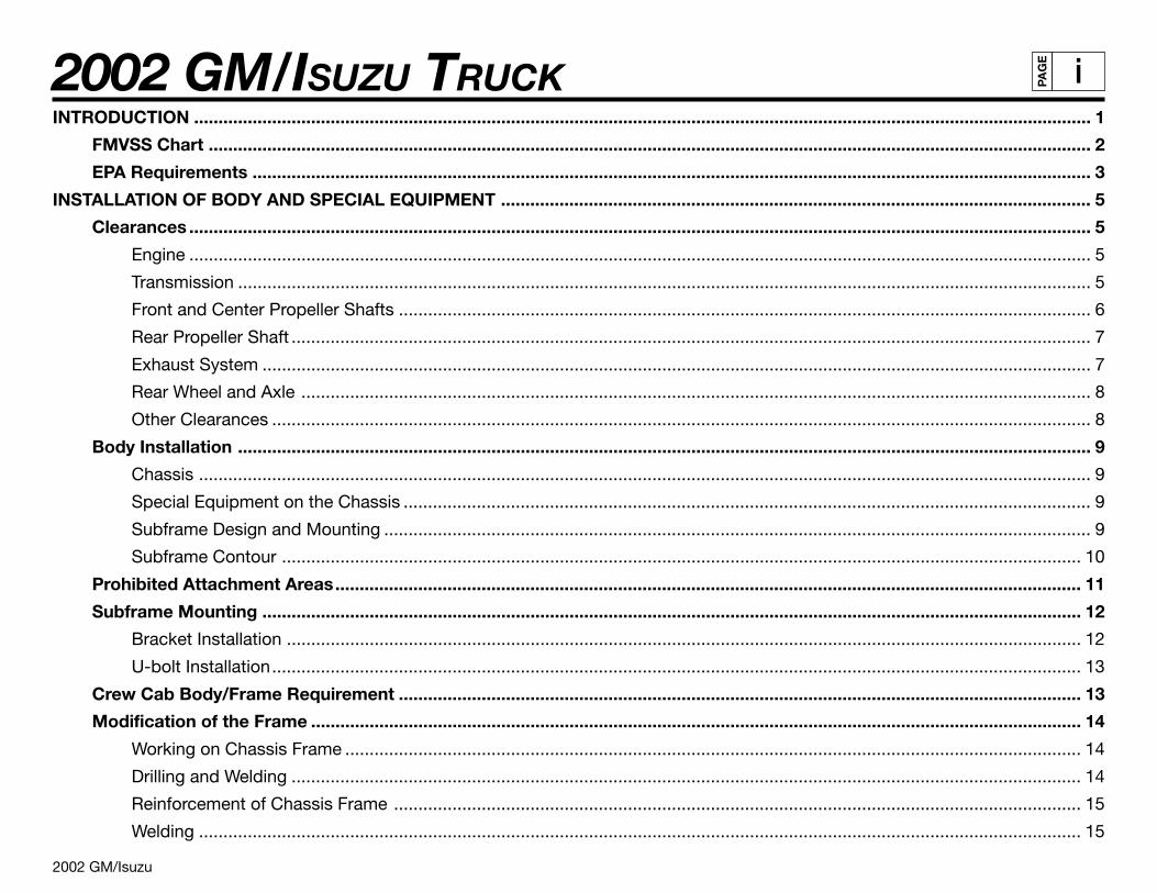
2002 GM/ISUZU TRUCK 2002 GM/Isuzu i PAGE INTRODUCTION ........................................................................................................................................................................................ 1 FMVSS Chart ..................................................................................................................................................................................... 2 EPA Requirements ............................................................................................................................................................................ 3 INSTALLATION OF BODY AND SPECIAL EQUIPMENT ......................................................................................................................... 5 Clearances ......................................................................................................................................................................................... 5 Engine ......................................................................................................................................................................................... 5 Transmission ............................................................................................................................................................................... 5 Front and Center Propeller Shafts .............................................................................................................................................. 6 Rear Propeller Shaft .................................................................................................................................................................... 7 Exhaust System .......................................................................................................................................................................... 7 Rear Wheel and Axle .................................................................................................................................................................. 8 Other Clearances ........................................................................................................................................................................ 8 Body Installation ............................................................................................................................................................................... 9 Chassis ....................................................................................................................................................................................... 9 Special Equipment on the Chassis ............................................................................................................................................. 9 Subframe Design and Mounting ................................................................................................................................................. 9 Subframe Contour .................................................................................................................................................................... 10 Prohibited Attachment Areas ......................................................................................................................................................... 11 Subframe Mounting ........................................................................................................................................................................ 12 Bracket Installation ................................................................................................................................................................... 12 U-bolt Installation ...................................................................................................................................................................... 13 Crew Cab Body/Frame Requirement ............................................................................................................................................ 13 Modification of the Frame .............................................................................................................................................................. 14 Working on Chassis Frame ....................................................................................................................................................... 14 Drilling and Welding .................................................................................................................................................................. 14 Reinforcement of Chassis Frame ............................................................................................................................................. 15 Welding ..................................................................................................................................................................................... 15
Transcript of 2002 GM/ISUZU TRUCK AGE i · 2002 gm/isuzu truck 2002 gm/isuzu age iv weight distribution...
2002 GM/ISUZU TRUCK
2002 GM/Isuzu
iPA
GE
INTRODUCTION ........................................................................................................................................................................................ 1
FMVSS Chart ..................................................................................................................................................................................... 2
EPA Requirements ............................................................................................................................................................................ 3
INSTALLATION OF BODY AND SPECIAL EQUIPMENT ......................................................................................................................... 5
Clearances ......................................................................................................................................................................................... 5
Engine ......................................................................................................................................................................................... 5
Transmission ............................................................................................................................................................................... 5
Front and Center Propeller Shafts .............................................................................................................................................. 6
Rear Propeller Shaft .................................................................................................................................................................... 7
Exhaust System .......................................................................................................................................................................... 7
Rear Wheel and Axle .................................................................................................................................................................. 8
Other Clearances ........................................................................................................................................................................ 8
Body Installation ............................................................................................................................................................................... 9
Chassis ....................................................................................................................................................................................... 9
Special Equipment on the Chassis ............................................................................................................................................. 9
Subframe Design and Mounting ................................................................................................................................................. 9
Subframe Contour .................................................................................................................................................................... 10
Prohibited Attachment Areas......................................................................................................................................................... 11
Subframe Mounting ........................................................................................................................................................................ 12
Bracket Installation ................................................................................................................................................................... 12
U-bolt Installation...................................................................................................................................................................... 13
Crew Cab Body/Frame Requirement ............................................................................................................................................ 13
Modification of the Frame .............................................................................................................................................................. 14
Working on Chassis Frame ....................................................................................................................................................... 14
Drilling and Welding .................................................................................................................................................................. 14
Reinforcement of Chassis Frame ............................................................................................................................................. 15
Welding ..................................................................................................................................................................................... 15
2002 GM/ISUZU TRUCK
2002 GM/Isuzu
iiPA
GE
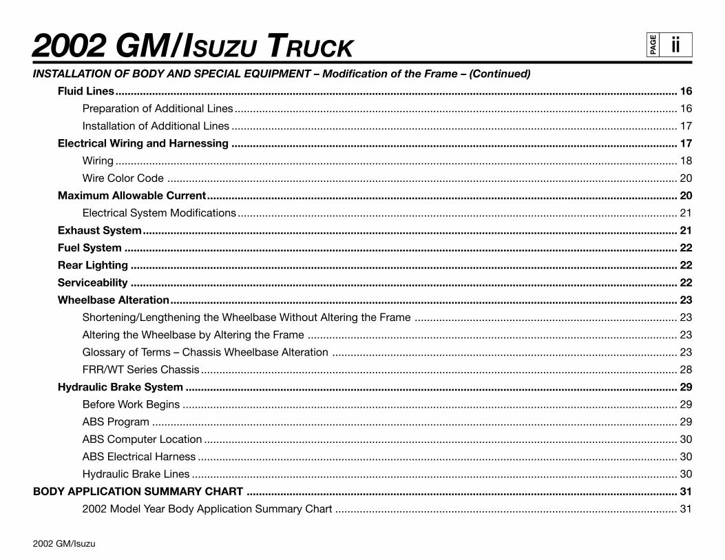
INSTALLATION OF BODY AND SPECIAL EQUIPMENT – Modification of the Frame – (Continued)
Fluid Lines........................................................................................................................................................................................ 16
Preparation of Additional Lines ................................................................................................................................................. 16
Installation of Additional Lines .................................................................................................................................................. 17
Electrical Wiring and Harnessing .................................................................................................................................................. 17
Wiring ........................................................................................................................................................................................ 18
Wire Color Code ....................................................................................................................................................................... 20
Maximum Allowable Current.......................................................................................................................................................... 20
Electrical System Modifications ................................................................................................................................................ 21
Exhaust System............................................................................................................................................................................... 21
Fuel System ..................................................................................................................................................................................... 22
Rear Lighting ................................................................................................................................................................................... 22
Serviceability ................................................................................................................................................................................... 22
Wheelbase Alteration...................................................................................................................................................................... 23
Shortening/Lengthening the Wheelbase Without Altering the Frame ...................................................................................... 23
Altering the Wheelbase by Altering the Frame ......................................................................................................................... 23
Glossary of Terms – Chassis Wheelbase Alteration ................................................................................................................. 23
FRR/WT Series Chassis ............................................................................................................................................................ 28
Hydraulic Brake System ................................................................................................................................................................. 29
Before Work Begins .................................................................................................................................................................. 29
ABS Program ............................................................................................................................................................................ 29
ABS Computer Location ........................................................................................................................................................... 30
ABS Electrical Harness ............................................................................................................................................................. 30
Hydraulic Brake Lines ............................................................................................................................................................... 30
BODY APPLICATION SUMMARY CHART ............................................................................................................................................. 31
2002 Model Year Body Application Summary Chart ................................................................................................................ 31
2002 GM/ISUZU TRUCK
2002 GM/Isuzu
iiiPA
GE
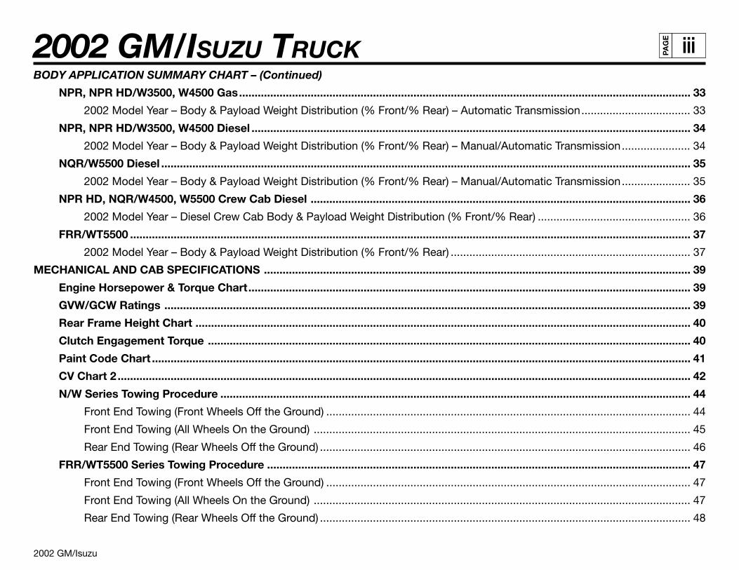
BODY APPLICATION SUMMARY CHART – (Continued)
NPR, NPR HD/W3500, W4500 Gas................................................................................................................................................. 33
2002 Model Year – Body & Payload Weight Distribution (% Front/% Rear) – Automatic Transmission................................... 33
NPR, NPR HD/W3500, W4500 Diesel ............................................................................................................................................. 34
2002 Model Year – Body & Payload Weight Distribution (% Front/% Rear) – Manual/Automatic Transmission...................... 34
NQR/W5500 Diesel .......................................................................................................................................................................... 35
2002 Model Year – Body & Payload Weight Distribution (% Front/% Rear) – Manual/Automatic Transmission...................... 35
NPR HD, NQR/W4500, W5500 Crew Cab Diesel .......................................................................................................................... 36
2002 Model Year – Diesel Crew Cab Body & Payload Weight Distribution (% Front/% Rear) ................................................. 36
FRR/WT5500 .................................................................................................................................................................................... 37
2002 Model Year – Body & Payload Weight Distribution (% Front/% Rear) ............................................................................. 37
MECHANICAL AND CAB SPECIFICATIONS ......................................................................................................................................... 39
Engine Horsepower & Torque Chart.............................................................................................................................................. 39
GVW/GCW Ratings ......................................................................................................................................................................... 39
Rear Frame Height Chart ............................................................................................................................................................... 40
Clutch Engagement Torque ........................................................................................................................................................... 40
Paint Code Chart ............................................................................................................................................................................. 41
CV Chart 2 ........................................................................................................................................................................................ 42
N/W Series Towing Procedure ....................................................................................................................................................... 44
Front End Towing (Front Wheels Off the Ground) ..................................................................................................................... 44
Front End Towing (All Wheels On the Ground) ......................................................................................................................... 45
Rear End Towing (Rear Wheels Off the Ground) ....................................................................................................................... 46
FRR/WT5500 Series Towing Procedure ........................................................................................................................................ 47
Front End Towing (Front Wheels Off the Ground) ..................................................................................................................... 47
Front End Towing (All Wheels On the Ground) ......................................................................................................................... 47
Rear End Towing (Rear Wheels Off the Ground) ....................................................................................................................... 48
2002 GM/ISUZU TRUCK
2002 GM/Isuzu
ivPA
GE
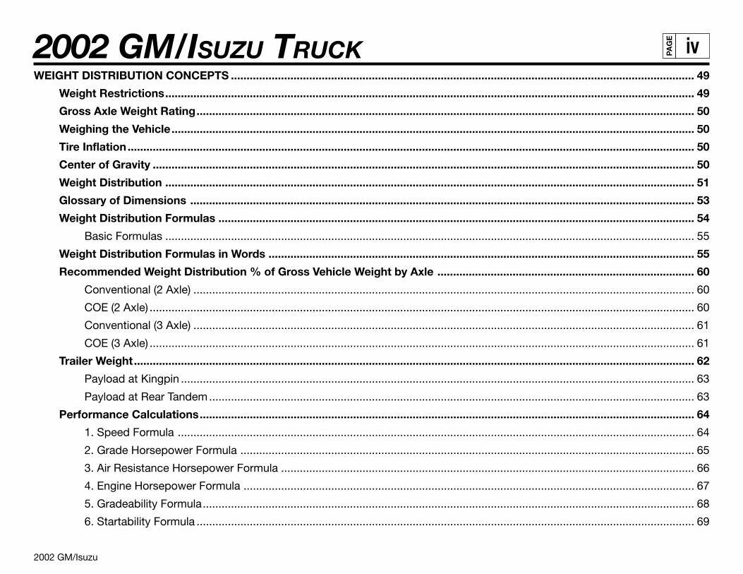
WEIGHT DISTRIBUTION CONCEPTS .................................................................................................................................................... 49
Weight Restrictions......................................................................................................................................................................... 49
Gross Axle Weight Rating............................................................................................................................................................... 50
Weighing the Vehicle....................................................................................................................................................................... 50
Tire Inflation..................................................................................................................................................................................... 50
Center of Gravity ............................................................................................................................................................................. 50
Weight Distribution ......................................................................................................................................................................... 51
Glossary of Dimensions ................................................................................................................................................................. 53
Weight Distribution Formulas ........................................................................................................................................................ 54
Basic Formulas ......................................................................................................................................................................... 55
Weight Distribution Formulas in Words ........................................................................................................................................ 55
Recommended Weight Distribution % of Gross Vehicle Weight by Axle .................................................................................. 60
Conventional (2 Axle) ................................................................................................................................................................ 60
COE (2 Axle) .............................................................................................................................................................................. 60
Conventional (3 Axle) ................................................................................................................................................................ 61
COE (3 Axle) .............................................................................................................................................................................. 61
Trailer Weight................................................................................................................................................................................... 62
Payload at Kingpin .................................................................................................................................................................... 63
Payload at Rear Tandem........................................................................................................................................................... 63
Performance Calculations.............................................................................................................................................................. 64
1. Speed Formula ..................................................................................................................................................................... 64
2. Grade Horsepower Formula ................................................................................................................................................. 65
3. Air Resistance Horsepower Formula .................................................................................................................................... 66
4. Engine Horsepower Formula ................................................................................................................................................ 67
5. Gradeability Formula............................................................................................................................................................. 68
6. Startability Formula ............................................................................................................................................................... 69
2002 GM/ISUZU TRUCK
2002 GM/Isuzu
vPA
GE
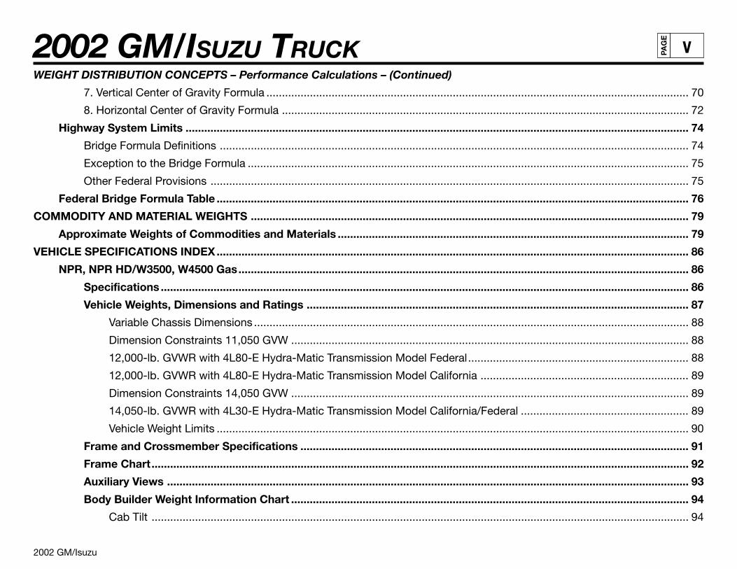
WEIGHT DISTRIBUTION CONCEPTS – Performance Calculations – (Continued)
7. Vertical Center of Gravity Formula ........................................................................................................................................ 70
8. Horizontal Center of Gravity Formula ................................................................................................................................... 72
Highway System Limits .................................................................................................................................................................. 74
Bridge Formula Definitions ....................................................................................................................................................... 74
Exception to the Bridge Formula .............................................................................................................................................. 75
Other Federal Provisions .......................................................................................................................................................... 75
Federal Bridge Formula Table ........................................................................................................................................................ 76
COMMODITY AND MATERIAL WEIGHTS ............................................................................................................................................. 79
Approximate Weights of Commodities and Materials ................................................................................................................. 79
VEHICLE SPECIFICATIONS INDEX........................................................................................................................................................ 86
NPR, NPR HD/W3500, W4500 Gas................................................................................................................................................. 86
Specifications .......................................................................................................................................................................... 86
Vehicle Weights, Dimensions and Ratings ........................................................................................................................... 87
Variable Chassis Dimensions ............................................................................................................................................ 88
Dimension Constraints 11,050 GVW ................................................................................................................................ 88
12,000-lb. GVWR with 4L80-E Hydra-Matic Transmission Model Federal....................................................................... 88
12,000-lb. GVWR with 4L80-E Hydra-Matic Transmission Model California ................................................................... 89
Dimension Constraints 14,050 GVW ................................................................................................................................ 89
14,050-lb. GVWR with 4L30-E Hydra-Matic Transmission Model California/Federal ...................................................... 89
Vehicle Weight Limits ........................................................................................................................................................ 90
Frame and Crossmember Specifications ............................................................................................................................. 91
Frame Chart............................................................................................................................................................................. 92
Auxiliary Views ........................................................................................................................................................................ 93
Body Builder Weight Information Chart ................................................................................................................................ 94
Cab Tilt ............................................................................................................................................................................. 94
2002 GM/ISUZU TRUCK
2002 GM/Isuzu
viPA
GE
VEHICLE SPECIFICATIONS INDEX – NPR, NPR HD/W3500, W4500 Gas – (Continued)
Center of Gravity ............................................................................................................................................................... 95
Front Axle Chart ...................................................................................................................................................................... 96
Rear Axle Chart ....................................................................................................................................................................... 97
Definitions ......................................................................................................................................................................... 98
Formulas for Calculating Rear Width and Height Dimensions ......................................................................................... 98
Suspension Deflection Charts – NPR/W3500 Gas ............................................................................................................... 99
Suspension Deflection Charts – NPR HD/W4500 Gas ....................................................................................................... 100
Tire and Disc Wheel Chart ................................................................................................................................................... 101
Tire .................................................................................................................................................................................. 101
Disc Wheel ...................................................................................................................................................................... 101
Propeller Shaft ...................................................................................................................................................................... 102
Brake System Schematic, 12,000 GVW............................................................................................................................... 104
Vacuum Over Hydraulic .................................................................................................................................................. 104
Brake System Schematic, 14,050 GVW............................................................................................................................... 105
Vacuum Over Hydraulic .................................................................................................................................................. 105
Through the Rail Fuel Fill...................................................................................................................................................... 106
Installation Instructions ................................................................................................................................................... 106
Rear View Fuel Fill ........................................................................................................................................................ 107
Top View Fuel Fill .......................................................................................................................................................... 108
Top View......................................................................................................................................................................... 109
Through the Rail Fuel Fill Frame Hole......................................................................................................................... 110
Fuel Fill Parts Illustration ............................................................................................................................................. 111
Fuel Fill Parts List ......................................................................................................................................................... 112
NPR, NPR HD/W3500, W4500 Diesel ........................................................................................................................................... 113
Specifications ........................................................................................................................................................................ 113
2002 GM/ISUZU TRUCK
2002 GM/Isuzu
viiPA
GE
VEHICLE SPECIFICATIONS INDEX – NPR, NPR HD/W3500, W4500 Diesel – (Continued)
Vehicle Weights, Dimensions and Ratings ......................................................................................................................... 114
Variable Chassis Dimensions .......................................................................................................................................... 115
Dimension Constants ..................................................................................................................................................... 115
In-Frame Tank 12,000-lb. GVWR Manual Transmission Model ...................................................................................... 115
In-Frame Tank 14,500-lb. GVWR Manual Transmission Model ...................................................................................... 116
In-Frame Tank 12,000-lb. GVWR Automatic Transmission Model ................................................................................. 116
In-Frame Tank 14,500-lb. GVWR Automatic Transmission Model ................................................................................. 116
Side-Mounted Tank 12,000-lb. GVWR Manual Transmission Model.............................................................................. 117
Side-Mounted Tank 14,500-lb. GVWR Manual Transmission Model.............................................................................. 117
Side-Mounted Tank 12,000-lb. GVWR Automatic Transmission Model ......................................................................... 117
Side-Mounted Tank 14,500-lb. GVWR Automatic Transmission Model ......................................................................... 118
Vehicle Weight Limits ...................................................................................................................................................... 118
Frame and Crossmember Specifications ........................................................................................................................... 119
Frame Chart........................................................................................................................................................................... 120
Auxiliary Views ...................................................................................................................................................................... 121
Body Builder Weight Information Chart .............................................................................................................................. 122
Cab Tilt ........................................................................................................................................................................... 122
Center of Gravity ............................................................................................................................................................. 123
Front Axle Chart .................................................................................................................................................................... 124
Rear Axle Chart ..................................................................................................................................................................... 125
Definitions ....................................................................................................................................................................... 126
Formulas for Calculating Rear Width and Height Dimensions ....................................................................................... 126
Suspension Deflection Charts ............................................................................................................................................. 127
Tire and Disc Wheel Chart ................................................................................................................................................... 128
Tire .................................................................................................................................................................................. 128
2002 GM/ISUZU TRUCK
2002 GM/Isuzu
viiiPA
GE
VEHICLE SPECIFICATIONS INDEX – NPR, NPR HD/W3500, W4500 Diesel – (Continued)
Disc Wheel ...................................................................................................................................................................... 128
Propeller Shaft ...................................................................................................................................................................... 129
PTO Location, Drive Gear and Opening Information ......................................................................................................... 131
Opening Diagram ............................................................................................................................................................ 132
Brake System Schematic, 12,000 GVW............................................................................................................................... 133
Vacuum Over Hydraulic .................................................................................................................................................. 133
Brake System Schematic, 14,500 GVW............................................................................................................................... 134
Vacuum Over Hydraulic .................................................................................................................................................. 134
In-Frame Diesel Fuel Filler ................................................................................................................................................... 135
Installation Instructions ................................................................................................................................................... 135
Rear View Fuel Fill ........................................................................................................................................................ 136
Top View Fuel Fill .......................................................................................................................................................... 137
Hose Modification for Various Width Bodies ............................................................................................................. 138
Through the Rail Fuel Fill Frame Hole......................................................................................................................... 139
Fuel Fill Parts Illustration ............................................................................................................................................. 140
Fuel Fill Parts List ......................................................................................................................................................... 141
NQR/W5500 Diesel ........................................................................................................................................................................ 142
Specifications ........................................................................................................................................................................ 142
Vehicle Weights, Dimensions and Ratings ......................................................................................................................... 143
Variable Chassis Dimensions .......................................................................................................................................... 144
Dimension Constraints ................................................................................................................................................... 144
In-Frame Tank 17,950-lb. GVWR Manual Transmission Model ...................................................................................... 144
In-Frame Tank 17,950-lb. GVWR Automatic Transmission Model ................................................................................. 145
Side-Mounted Tank 17,950-lb. GVWR Manual Transmission Model.............................................................................. 145
Side-Mounted Tank 17,950-lb. GVWR Automatic Transmission Model ......................................................................... 145
2002 GM/ISUZU TRUCK
2002 GM/Isuzu
ixPA
GE
VEHICLE SPECIFICATIONS INDEX – NQR/W5500 Diesel – (Continued)
Vehicle Weight Limits ...................................................................................................................................................... 146
Frame and Crossmember Specifications ........................................................................................................................... 147
Frame Chart........................................................................................................................................................................... 148
Auxiliary Views ...................................................................................................................................................................... 149
Body Builder Weight Information Chart .............................................................................................................................. 150
Cab Tilt ........................................................................................................................................................................... 150
Center of Gravity ............................................................................................................................................................. 151
Front Axle Chart .................................................................................................................................................................... 152
Rear Axle Chart ..................................................................................................................................................................... 153
Definitions ....................................................................................................................................................................... 154
Formulas for Calculating Rear Width and Height Dimensions ....................................................................................... 154
Suspension Deflection Charts ............................................................................................................................................. 155
Tire and Disc Wheel Chart ................................................................................................................................................... 156
Tire .................................................................................................................................................................................. 156
Disc Wheel ...................................................................................................................................................................... 156
Propeller Shaft ...................................................................................................................................................................... 157
PTO Location, Drive Gear and Opening Information ......................................................................................................... 159
Opening Diagram ............................................................................................................................................................ 160
Brake System Diagram......................................................................................................................................................... 161
Vacuum Over Hydraulic .................................................................................................................................................. 161
Diesel Fuel Fill ....................................................................................................................................................................... 162
Installation Instructions ................................................................................................................................................... 162
Rear View Fuel Fill ........................................................................................................................................................ 163
Top View Fuel Fill .......................................................................................................................................................... 164
Through the Rail Fuel Fill Frame Hole......................................................................................................................... 165
2002 GM/ISUZU TRUCK
2002 GM/Isuzu
xPA
GE
VEHICLE SPECIFICATIONS INDEX – NQR/W5500 Diesel – (Continued)
NQR/W5500 Diesel Fuel Fill Parts Illustration ............................................................................................................ 166
NQR/W5500 Diesel Fuel Fill Parts List ........................................................................................................................ 167
NPR HD, NQR/W4500, W5500 Crew Cab Diesel ........................................................................................................................ 168
Specifications ........................................................................................................................................................................ 168
Vehicle Weights, Dimensions and Ratings ......................................................................................................................... 169
NPR HD/W4500 Variable Chassis Dimensions............................................................................................................... 170
NPR HD/W4500 Dimension Constants .......................................................................................................................... 170
NPR HD/W4500 In-Frame Tank 14,500-lb. GVWR Automatic Transmission Model ...................................................... 170
NPR HD/W4500 Side-Mounted Tank 14,500-lb. GVWR Automatic Transmission Model .............................................. 170
NQR/W5500 Variable Chassis Dimensions .................................................................................................................... 171
NQR/W5500 Dimension Constraints .............................................................................................................................. 171
NQR/W5500 In-Frame Tank 17,950-lb. GVWR Automatic Transmission Model ............................................................ 171
NQR/W5500 Side-Mounted Tank 17,950-lb. GVWR Automatic Transmission Model .................................................... 171
Vehicle Weight Limits ...................................................................................................................................................... 172
Frame and Crossmember Specifications ........................................................................................................................... 173
Frame Chart........................................................................................................................................................................... 174
Auxiliary Views ...................................................................................................................................................................... 175
Body Builder Weight Information Chart .............................................................................................................................. 176
NPR HD/W4500 .............................................................................................................................................................. 176
Center of Gravity ............................................................................................................................................................. 176
NQR/W5500.................................................................................................................................................................... 177
Center of Gravity ............................................................................................................................................................. 177
Front Axle Chart NPR HD/W4500 ........................................................................................................................................ 178
Front Axle Chart NQR/W5500 .............................................................................................................................................. 179
Rear Axle Chart NPR HD/W4500 ......................................................................................................................................... 180
2002 GM/ISUZU TRUCK
2002 GM/Isuzu
xiPA
GE
VEHICLE SPECIFICATIONS INDEX – NPR HD, NQR/W4500, W5500 Crew Cab Diesel – (Continued)
Definitions ....................................................................................................................................................................... 181
Formulas for Calculating Rear Width and Height Dimensions ....................................................................................... 181
Rear Axle Chart NQR/W5500 ............................................................................................................................................... 182
Definitions ....................................................................................................................................................................... 183
Formulas for Calculating Rear Width and Height Dimensions ....................................................................................... 183
Suspension Deflection Charts NPR HD/W4500 ................................................................................................................. 184
Suspension Deflection Charts NQR/W5500 ....................................................................................................................... 185
Tire and Disc Wheel Chart NPR HD/W4500........................................................................................................................ 186
Tire .................................................................................................................................................................................. 186
Disc Wheel ...................................................................................................................................................................... 186
Tire and Disc Wheel Chart NQR/W5500.............................................................................................................................. 187
Tire .................................................................................................................................................................................. 187
Disc Wheel ...................................................................................................................................................................... 187
Propeller Shaft NPR HD/W4500 ........................................................................................................................................... 188
Propeller Shaft NQR/W5500 ................................................................................................................................................. 189
PTO Location, Drive Gear and Opening Information ......................................................................................................... 191
Opening Diagram ............................................................................................................................................................ 192
Brake System Diagram 14,500 GVW ................................................................................................................................... 193
Vacuum Over Hydraulic .................................................................................................................................................. 193
Brake System Diagram 17,950 GVW ................................................................................................................................... 194
Vacuum Over Hydraulic .................................................................................................................................................. 194
Diesel Fuel Fill ....................................................................................................................................................................... 195
Installation Instructions ................................................................................................................................................... 195
Rear View Fuel Fill ........................................................................................................................................................ 196
Top View Fuel Fill .......................................................................................................................................................... 197
2002 GM/ISUZU TRUCK
2002 GM/Isuzu
xiiPA
GE
VEHICLE SPECIFICATIONS INDEX – NPR HD, NQR/W4500, W5500 Crew Cab Diesel – (Continued)
Hose Modification for Various Width Bodies ............................................................................................................. 198
Through the Rail Fuel Fill Frame Hole......................................................................................................................... 199
Fuel Fill Parts Illustration ............................................................................................................................................. 200
Fuel Fill Parts List ......................................................................................................................................................... 201
FRR/WT5500 .................................................................................................................................................................................. 202
Specifications ........................................................................................................................................................................ 202
Vehicle Weights, Dimensions and Ratings ......................................................................................................................... 203
Variable Chassis Dimensions .......................................................................................................................................... 204
Dimension Constants ..................................................................................................................................................... 204
19,500-lb. GVW With 6-Speed Manual Transmission .................................................................................................... 204
18,000-lb. GVW With 6-Speed Manual Transmission .................................................................................................... 205
19,500-lb. GVW With Automatic Transmission ............................................................................................................... 205
18,000-lb. GVW With Automatic Transmission ............................................................................................................... 205
Truck Weight Limits......................................................................................................................................................... 206
Technical Notes .............................................................................................................................................................. 206
Frame and Crossmember Specifications ........................................................................................................................... 206
Frame Chart........................................................................................................................................................................... 208
Auxiliary Views ...................................................................................................................................................................... 209
Body Builder Weight Information Chart .............................................................................................................................. 210
Cab Tilt ........................................................................................................................................................................... 210
Center of Gravity ............................................................................................................................................................. 211
Front Axle Chart .................................................................................................................................................................... 212
Rear Axle Chart ..................................................................................................................................................................... 213
Definitions ....................................................................................................................................................................... 214
Formulas for Calculating Rear Width and Height Dimensions ....................................................................................... 214
2002 GM/ISUZU TRUCK
2002 GM/Isuzu
xiiiPA
GE
VEHICLE SPECIFICATIONS INDEX – FRR/WT5500 – (Continued)
Suspension Deflection Charts ............................................................................................................................................. 215
Tire and Disc Wheel Chart ................................................................................................................................................... 216
Tire .................................................................................................................................................................................. 216
Disc Wheel ...................................................................................................................................................................... 216
Propeller Shaft ...................................................................................................................................................................... 217
PTO Location, Drive Gear and Opening Information ......................................................................................................... 220
Opening Diagram ............................................................................................................................................................ 221
Brake System Schematic ..................................................................................................................................................... 222
Vacuum Over Hydraulic .................................................................................................................................................. 222
Allison Transmission Rating Guide...................................................................................................................................... 223
NPR, NPR HD/W3500, W4500 Gas Electrical.............................................................................................................................. 224
Symbols ................................................................................................................................................................................. 224
Abbreviations ........................................................................................................................................................................ 225
Wiring ..................................................................................................................................................................................... 226
Wire Color ....................................................................................................................................................................... 226
Distinction of Circuit by Wire Base Color ....................................................................................................................... 227
Wire Size ......................................................................................................................................................................... 227
Grounding Point Location (J-61).......................................................................................................................................... 229
Grounding Point Location (J-9) ........................................................................................................................................... 230
Grounding Point Location (E-54, E-53) ............................................................................................................................... 231
Grounding Point Location (E-56, E-55) ............................................................................................................................... 232
Grounding Point Location (E-39, E-38) ............................................................................................................................... 233
Reference Table of Grounding Point ................................................................................................................................... 234
NPR/W3500 Body Room Light, ID and Marker Lamp, and Back Up Lamp Connector Location .................................. 235
NPR/W3500 Body Connectors LH Frame ...................................................................................................................... 235
2002 GM/ISUZU TRUCK
2002 GM/Isuzu
xivPA
GE
VEHICLE SPECIFICATIONS INDEX – NPR, NPR HD/W3500, W4500 Gas Electrical – (Continued)
NPR/W3500 Body Connectors EOF ............................................................................................................................... 235
Dome and Interior Lights Circuit Diagram ......................................................................................................................... 236
Park, Tail, License and I.D. Lights Circuit Diagram ........................................................................................................... 237
Fuse Location ........................................................................................................................................................................ 238
Fuse Box ................................................................................................................................................................................ 239
Relay Location ...................................................................................................................................................................... 241
Cab Relay............................................................................................................................................................................... 242
Hidden Fuse Box ................................................................................................................................................................... 242
Relay Box Outside Cab......................................................................................................................................................... 243
Auxiliary Power Source Circuit Diagram ............................................................................................................................ 244
Sound System Circuit Diagram ........................................................................................................................................... 245
Horn Circuit Diagram............................................................................................................................................................ 246
Back-Up Lights Circuit Diagram ......................................................................................................................................... 247
Turn and Hazard Lights Circuit Diagram ............................................................................................................................ 248
Turn and Hazard Lights Circuit Diagram ............................................................................................................................ 249
Fuel Tank Sending Unit Resistance..................................................................................................................................... 250
NPR, NPR HD, NQR/W3500, W4500, W5500 Diesel Electrical .................................................................................................. 251
Symbols ................................................................................................................................................................................. 251
Abbreviations ........................................................................................................................................................................ 252
Wiring ..................................................................................................................................................................................... 253
Wire Color ....................................................................................................................................................................... 253
Distinction of Circuit by Wire Base Color ....................................................................................................................... 254
Wire Size ......................................................................................................................................................................... 254
Grounding Point Location (B-1) ........................................................................................................................................... 256
Grounding Point Location (B-7) ........................................................................................................................................... 257
2002 GM/ISUZU TRUCK
2002 GM/Isuzu
xvPA
GE
VEHICLE SPECIFICATIONS INDEX – NPR, NPR HD, NQR/W3500, W4500, W5500 Diesel Electrical – (Continued)
Grounding Point Location (J-9) ........................................................................................................................................... 258
Reference Table of Grounding Point ................................................................................................................................... 259
NPR, NQR/W3500, W5500 Body Room Light, ID and Marker Lamp, and Back Up Lamp Connector Location........... 260
NPR, NQR/W3500, W5500 Body Connectors LH Frame ............................................................................................... 260
NPR, NQR/W3500, W5500 Body Connectors EOF........................................................................................................ 260
Dome and Interior Lights Circuit Diagram ......................................................................................................................... 261
Park, Tail, License and I.D. Lights Circuit Diagram ........................................................................................................... 262
Fuse Location ........................................................................................................................................................................ 263
Fuse Box ................................................................................................................................................................................ 264
Relay Location ...................................................................................................................................................................... 266
Cab Relay............................................................................................................................................................................... 267
Hidden Fuse Box ................................................................................................................................................................... 267
Relay Box Outside Cab......................................................................................................................................................... 268
Auxiliary Power Source Circuit Diagram ............................................................................................................................ 269
Horn Circuit Diagram............................................................................................................................................................ 270
Back-Up Lights Circuit Diagram ......................................................................................................................................... 271
Sound System Circuit Diagram ........................................................................................................................................... 272
Engine Stop Motor Circuit Diagram .................................................................................................................................... 273
Turn and Hazard Lights Circuit Diagram ............................................................................................................................ 274
Fuel Tank Sending Unit Resistance (In-Frame Tank) ......................................................................................................... 275
Fuel Tank Sending Unit Resistance (Side-Mounted Tank) ................................................................................................ 276
FRR/WT5500 Electrical ................................................................................................................................................................. 277
FRR/WT5500 Series Taillight Connectors ........................................................................................................................... 277
FRR/WT5500 Body Room Light, I.D. and Marker Lamp, and Back Up Lamp Connector Location .............................. 277
2002 GM/Isuzu
2002 GM/ISUZU TRUCK 1PA
GE
INTRODUCTION
This guide has been provided as an aid to final stage manufacturers in determining conformity to the applicable Emission Control andFederal Motor Vehicle Safety Standards. Final stage manufacturers should maintain current knowledge of all Emission Regulations andFederal Motor Vehicle Safety Standards and be aware of their specific responsibility in regards to each standard.
Any manufacturer making material alterations to this incomplete vehicle during the process of manufacturing the complete vehicle should beconstantly alert to all effects, direct or indirect, on other components, assemblies or systems caused by such alterations. No alterationsshould be made to the incomplete vehicle that directly or indirectly results in any either component, assembly or system being in nonconfor-mance with applicable Emission Regulations or Federal Motor Vehicle Safety Standards.
GMICT will honor its warranty commitment (for the cab-chassis only), to the ultimate consumer, provided: (1) the final stage manufacturerhas not made any alterations or modifications which do not conform to any applicable laws, regulations or standards, or adversely affect theoperation of the cab-chassis; and (2) the final stage manufacturer complied with the instructions contained in this guide with respect to thecompletion of the vehicle. Otherwise, the warranty becomes the responsibility of the final stage manufacturer.
The final stage manufacturer is solely responsible for the final certification of the vehicle and for compliance with Emission Control andFederal Motor Vehicle Safety standards. The information contained in this guide has been provided for the final stage manufacturer’sinformation and guidance.
This guide contains information pertaining to the NPR/W3500 Gas, NPR/W3500 Diesel, NQR/W5500 Diesel, NPR HD, NQR/W4500, W5500Diesel Crew Cab and FRR/WT5500 Series Chassis Cab.
Following is a list of Federal Motor Vehicle Safety Standards applicable to those vehicles with a GVWR greater than 10,000 lbs. Please referto the chart on the next page.
2002 GM/Isuzu
2002 GM/ISUZU TRUCK 2PA
GE
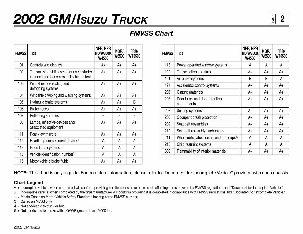
FMVSS Chart
NOTE: This chart is only a guide. For complete information, please refer to “Document for Incomplete Vehicle” provided with each chassis.
Chart LegendA = Incomplete vehicle; when completed will conform providing no alterations have been made affecting items covered by FMVSS regulations and “Document for Incomplete Vehicle.”B = Incomplete vehicle; when completed by the final manufacturer will conform providing it is completed in compliance with FMVSS regulations and “Document for Incomplete Vehicle.”+ = Meets Canadian Motor Vehicle Safety Standards bearing same FMVSS number.3 = Canadian MVSS only.4 = Not applicable to truck or bus.5 = Not applicable to trucks with a GVWR greater than 10,000 lbs.
NPR, NPRNQR/ FRR/FMVSS Title HD/W3500,
W5500 WT5500W4500101 Controls and displays A+ A+ A+
102 Transmission shift lever sequence, starter A+ A+ A+interlock and transmission braking effect
103 Windshield defrosting and A+ A+ A+defogging systems
104 Windshield wiping and washing systems A+ A+ A+
105 Hydraulic brake systems A+ A+ B
106 Brake hoses A+ A+ A+
107 Reflecting surfaces – – –
108 Lamps, reflective devices and A+ A+ A+associated equipment
111 Rear view mirrors A+ A+ A+
112 Headlamp concealment devices3 A A A
113 Hood latch systems A A A
115 Vehicle identification number3 A A A
116 Motor vehicle brake fluids A+ A+ A+
NPR, NPRNQR/ FRR/FMVSS Title HD/W3500,
W5500 WT5500W4500118 Power operated window systems5 A A A
120 Tire selection and rims A+ A+ A+
121 Air brake systems B B A
124 Accelerator control systems A+ A+ A+
205 Glazing materials A+ A+ A+
206 Door locks and door retention A+ A+ A+components
207 Seating systems A+ A+ A+
208 Occupant crash protection A+ A+ A+
209 Seat belt assemblies A+ A+ A+
210 Seat belt assembly anchorages A+ A+ A+
211 Wheel nuts, wheel discs, and hub caps4,3 A A A
213 Child restraint systems A A A
302 Flammability of interior materials A+ A+ A+
2002 GM/Isuzu
2002 GM/ISUZU TRUCK 3PA
GE
EPA Requirements
NPR/W3500 Gas, NPR/W3500 Diesel, NQR/W5500 Diesel, NPR HD, NQR/W4500, W5500 Diesel Crew Cab and FRR/WT5500 SeriesChassis Cab
To assure that U.S.A. and Canada Emission Requirements are met, this Incomplete Vehicle must be completed in strict accordance with allinstructions contained in this document, especially the following instructions which relate to:
A Exhaust emission related components
B Noise emission related components
C Labels
A. EXHAUST EMISSION RELATED COMPONENTS
Compliance of this vehicle with EPA, California and Canada requirements will be maintained providing no alterations are made to thecomponents or systems identified below:
1. DIESEL VEHICLES 2. GASOLINE VEHICLES
Injection Pump Vehicle Control Module (VCM)Injector and High Pressure Lines Fuel Management SystemTurbocharger Air Induction SystemCharge Air Cooler and Charge Air Cooler Hoses Ignition SystemEngine Control Module (ECM) Catalytic Converter SystemEngine Speed Sensor Positive Crankcase Ventilation SystemEngine Coolant Temperature Sensor Exhaust Gas Recirculation SystemIntake Manifold Evaporative Emission Control SystemCatalytic Converter and Its Location Miscellaneous Items Used in Above SystemsVariable Swirl SystemExhaust Gas Recirculation System
ADDITIONAL CANADA MOTOR VEHICLE SAFETY STANDARDCMVSS NO. 1101–EMISSION DEVICECMVSS NO. 1102–CRANKCASE EMISSION (GASOLINE ENGINE ONLY)CMVSS NO. 1103–EXHAUST EMISSIONSCMVSS NO. 1104–OPACITY (DIESEL ENGINE ONLY)CMVSS NO. 1105–EVAPORATIVE EMISSION (GASOLINE ENGINE ONLY)
(EPA Requirements – continued on next page)
2002 GM/Isuzu
2002 GM/ISUZU TRUCK 4PA
GE
(EPA Requirements – continued from previous page)
B. NOISE EMISSION RELATED COMPONENTS
Compliance of this vehicle with EPA and Canada requirements will be maintained providing no alterations are made to the compo-nents or systems.
CMVSS NO. 1106–NOISE
This incomplete vehicle, when completed, will conform to the above statements except CMVSS-1106 providing no alterations aremade which effect the function, physical or mechanical properties, environment, locations or vital spatial clearances of the compo-nents identified below:
* Engine assembly * AxleExhaust emission control system * TiresP.C.V. system (if equipped) * Fan and drive
* Intake system Diesel fuel injection controls (if equipped)* Exhaust system Turbocharger and associated controls (if equipped)
Fuel system (if equipped) * Catalytic converter and its location* Transmission assembly Variable swirl system (if equipped)
Conformity with CMVSS 1106 is not determined solely by the design of the incomplete vehicle. When completed, it should conformto CMVSS 1106 providing no alterations are made to the noise attenuation components identified thus * in the above list.
C. LABELS
The emission control related information labels which are permanently affixed are required by government regulation and must not beobstructed from view or defaced so as to impair its visibility or legibility.
PART 3: RADIO NOISE
CANADIAN RADIO INTERFERENCE REGULATIONS
A. The following statement is applicable to NPR/W Series Chassis-Cab (Gasoline Engine Only).
This incomplete vehicle, when completed, will conform to the above regulations providing no alterations or substitutions are madewhich affect any parts or components identified below:
A. Distributor C. Spark plug wires
B. Ignition Wires
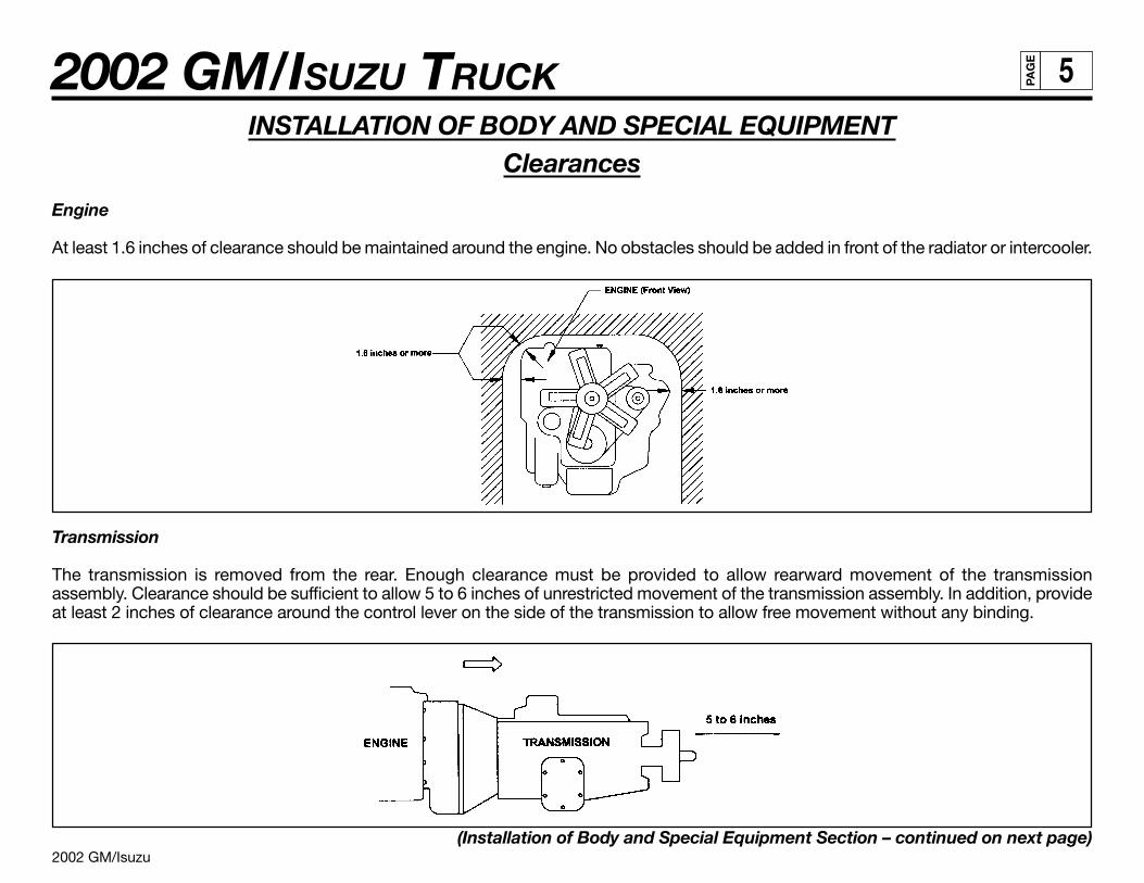
2002 GM/Isuzu
2002 GM/ISUZU TRUCK 5PA
GE
INSTALLATION OF BODY AND SPECIAL EQUIPMENTClearances
Engine
At least 1.6 inches of clearance should be maintained around the engine. No obstacles should be added in front of the radiator or intercooler.
Transmission
The transmission is removed from the rear. Enough clearance must be provided to allow rearward movement of the transmissionassembly. Clearance should be sufficient to allow 5 to 6 inches of unrestricted movement of the transmission assembly. In addition, provideat least 2 inches of clearance around the control lever on the side of the transmission to allow free movement without any binding.
(Installation of Body and Special Equipment Section – continued on next page)
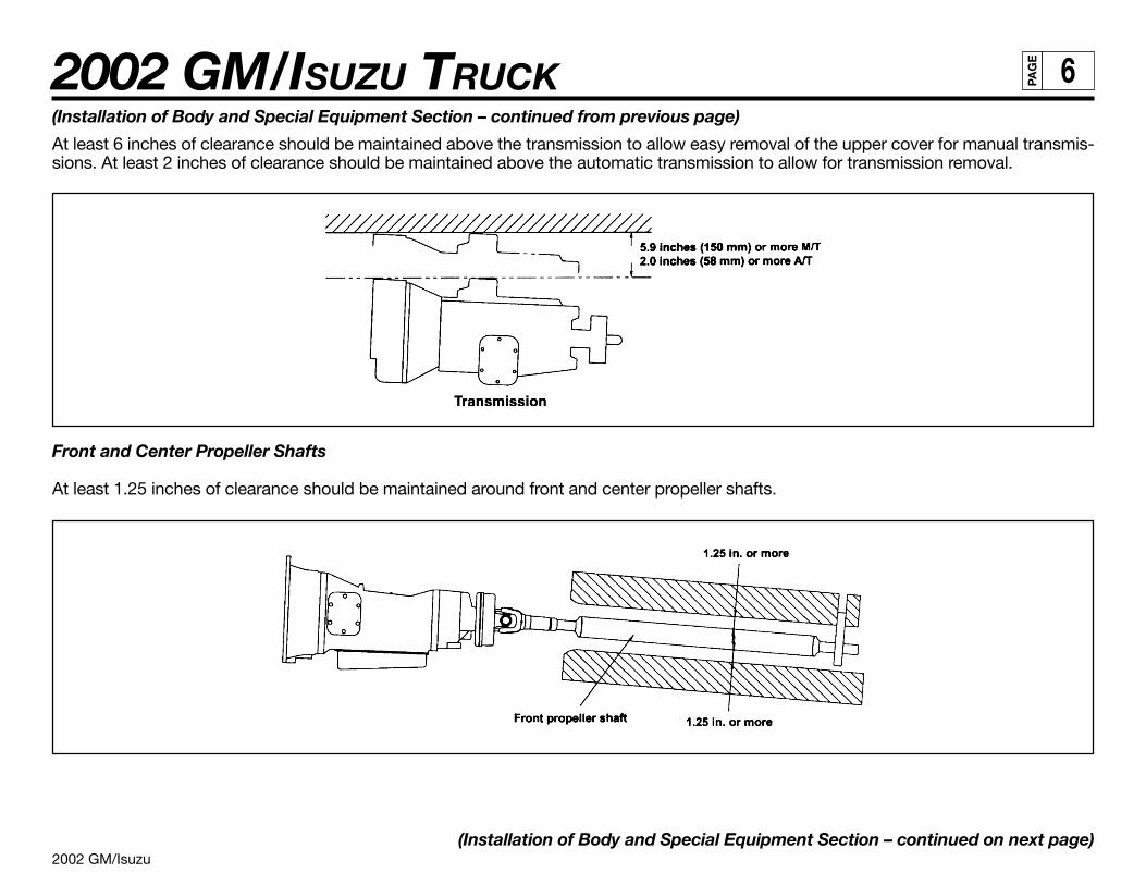
2002 GM/Isuzu
2002 GM/ISUZU TRUCK 6PA
GE
(Installation of Body and Special Equipment Section – continued from previous page)
At least 6 inches of clearance should be maintained above the transmission to allow easy removal of the upper cover for manual transmis-sions. At least 2 inches of clearance should be maintained above the automatic transmission to allow for transmission removal.
Front and Center Propeller Shafts
At least 1.25 inches of clearance should be maintained around front and center propeller shafts.
(Installation of Body and Special Equipment Section – continued on next page)
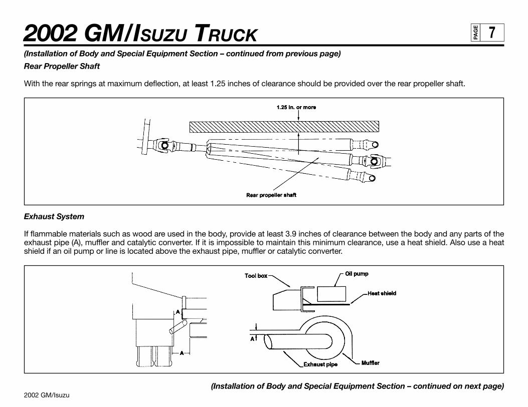
2002 GM/Isuzu
2002 GM/ISUZU TRUCK 7PA
GE
(Installation of Body and Special Equipment Section – continued from previous page)
Rear Propeller Shaft
With the rear springs at maximum deflection, at least 1.25 inches of clearance should be provided over the rear propeller shaft.
Exhaust System
If flammable materials such as wood are used in the body, provide at least 3.9 inches of clearance between the body and any parts of theexhaust pipe (A), muffler and catalytic converter. If it is impossible to maintain this minimum clearance, use a heat shield. Also use a heatshield if an oil pump or line is located above the exhaust pipe, muffler or catalytic converter.
(Installation of Body and Special Equipment Section – continued on next page)
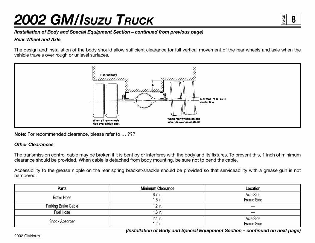
2002 GM/Isuzu
2002 GM/ISUZU TRUCK 8PA
GE
(Installation of Body and Special Equipment Section – continued from previous page)
Rear Wheel and Axle
The design and installation of the body should allow sufficient clearance for full vertical movement of the rear wheels and axle when thevehicle travels over rough or unlevel surfaces.
Note: For recommended clearance, please refer to … ???
Other Clearances
The transmission control cable may be broken if it is bent by or interferes with the body and its fixtures. To prevent this, 1 inch of minimumclearance should be provided. When cable is detached from body mounting, be sure not to bend the cable.
Accessibility to the grease nipple on the rear spring bracket/shackle should be provided so that serviceability with a grease gun is nothampered.
Parts Minimum Clearance Location
Brake Hose6.7 in. Axle Side1.6 in. Frame Side
Parking Brake Cable 1.2 in. —Fuel Hose 1.6 in. —
Shock Absorber2.4 in. Axle Side1.2 in. Frame Side
(Installation of Body and Special Equipment Section – continued on next page)
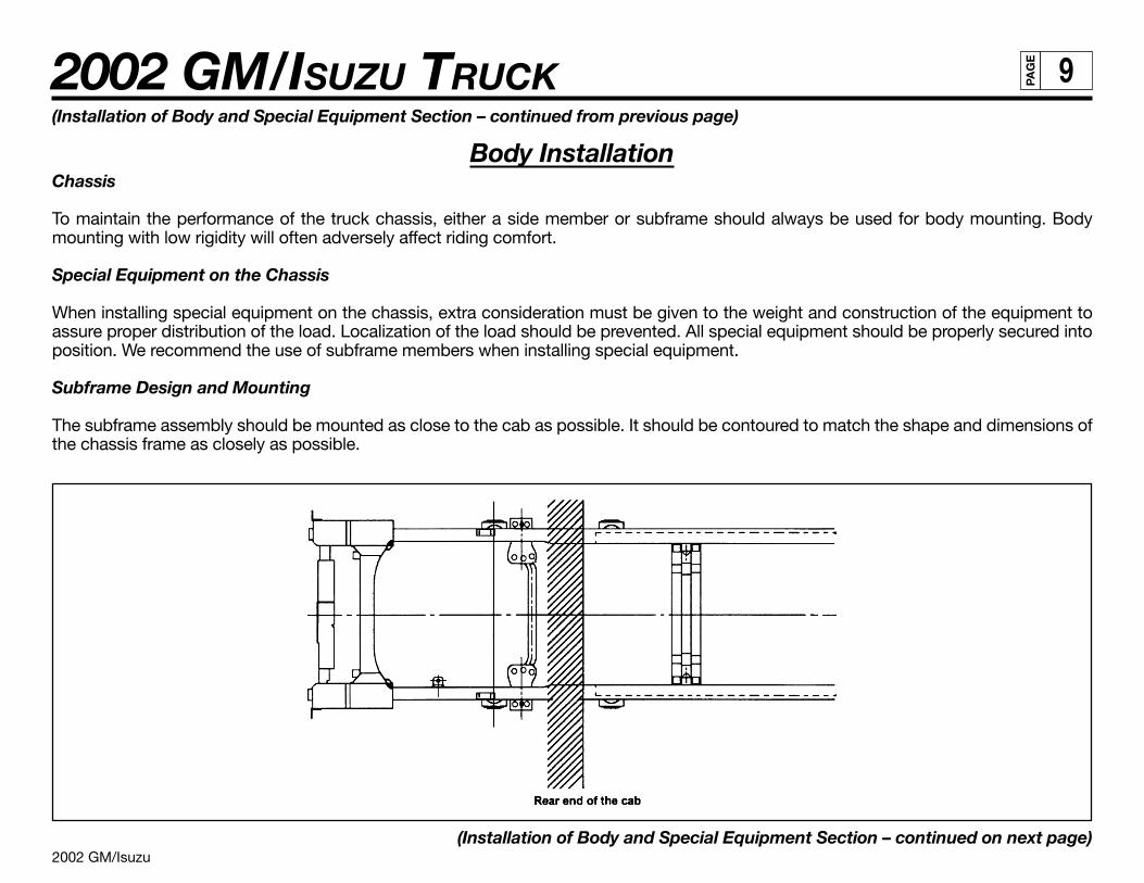
2002 GM/Isuzu
2002 GM/ISUZU TRUCK 9PA
GE
(Installation of Body and Special Equipment Section – continued from previous page)
Body InstallationChassis
To maintain the performance of the truck chassis, either a side member or subframe should always be used for body mounting. Bodymounting with low rigidity will often adversely affect riding comfort.
Special Equipment on the Chassis
When installing special equipment on the chassis, extra consideration must be given to the weight and construction of the equipment toassure proper distribution of the load. Localization of the load should be prevented. All special equipment should be properly secured intoposition. We recommend the use of subframe members when installing special equipment.
Subframe Design and Mounting
The subframe assembly should be mounted as close to the cab as possible. It should be contoured to match the shape and dimensions ofthe chassis frame as closely as possible.
(Installation of Body and Special Equipment Section – continued on next page)
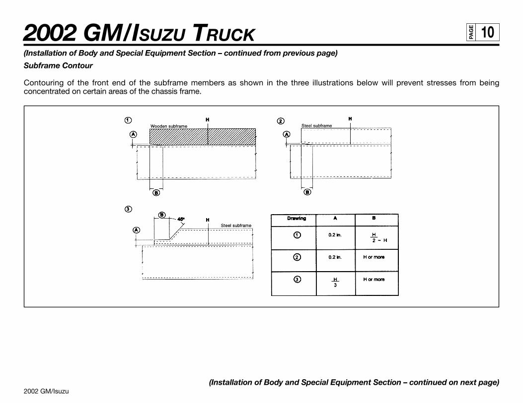
2002 GM/Isuzu
2002 GM/ISUZU TRUCK 10PA
GE
(Installation of Body and Special Equipment Section – continued from previous page)
Subframe Contour
Contouring of the front end of the subframe members as shown in the three illustrations below will prevent stresses from beingconcentrated on certain areas of the chassis frame.
(Installation of Body and Special Equipment Section – continued on next page)
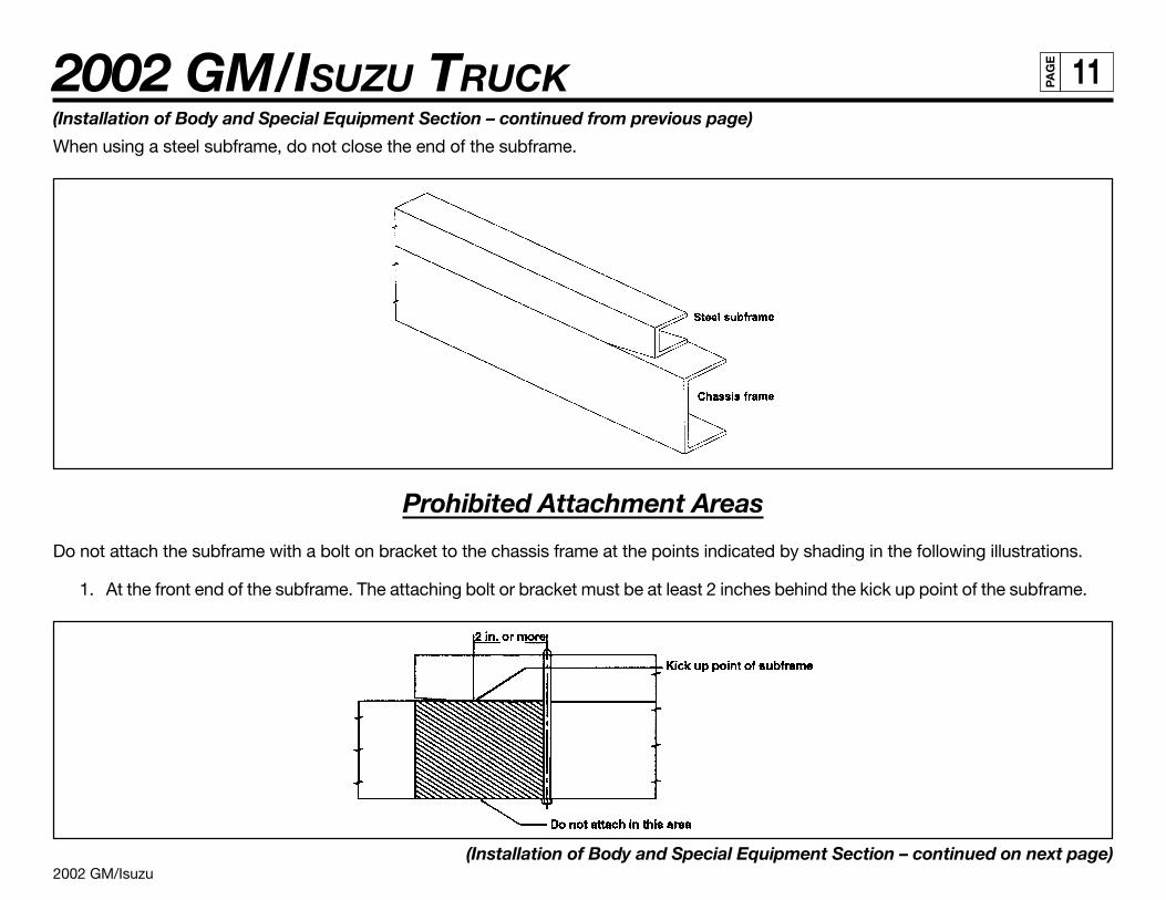
2002 GM/Isuzu
2002 GM/ISUZU TRUCK 11PA
GE
(Installation of Body and Special Equipment Section – continued from previous page)
When using a steel subframe, do not close the end of the subframe.
Prohibited Attachment Areas
Do not attach the subframe with a bolt on bracket to the chassis frame at the points indicated by shading in the following illustrations.
1. At the front end of the subframe. The attaching bolt or bracket must be at least 2 inches behind the kick up point of the subframe.
(Installation of Body and Special Equipment Section – continued on next page)
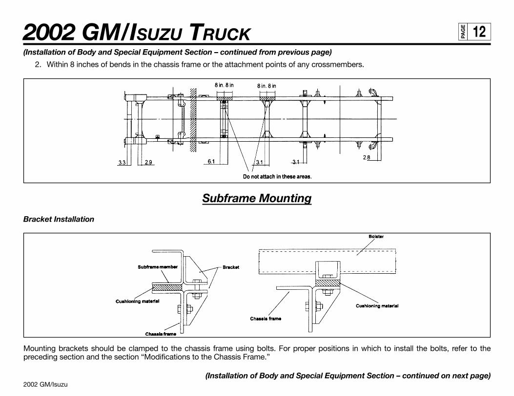
2002 GM/Isuzu
2002 GM/ISUZU TRUCK 12PA
GE
(Installation of Body and Special Equipment Section – continued from previous page)
2. Within 8 inches of bends in the chassis frame or the attachment points of any crossmembers.
Subframe Mounting
Bracket Installation
Mounting brackets should be clamped to the chassis frame using bolts. For proper positions in which to install the bolts, refer to thepreceding section and the section “Modifications to the Chassis Frame.”
(Installation of Body and Special Equipment Section – continued on next page)
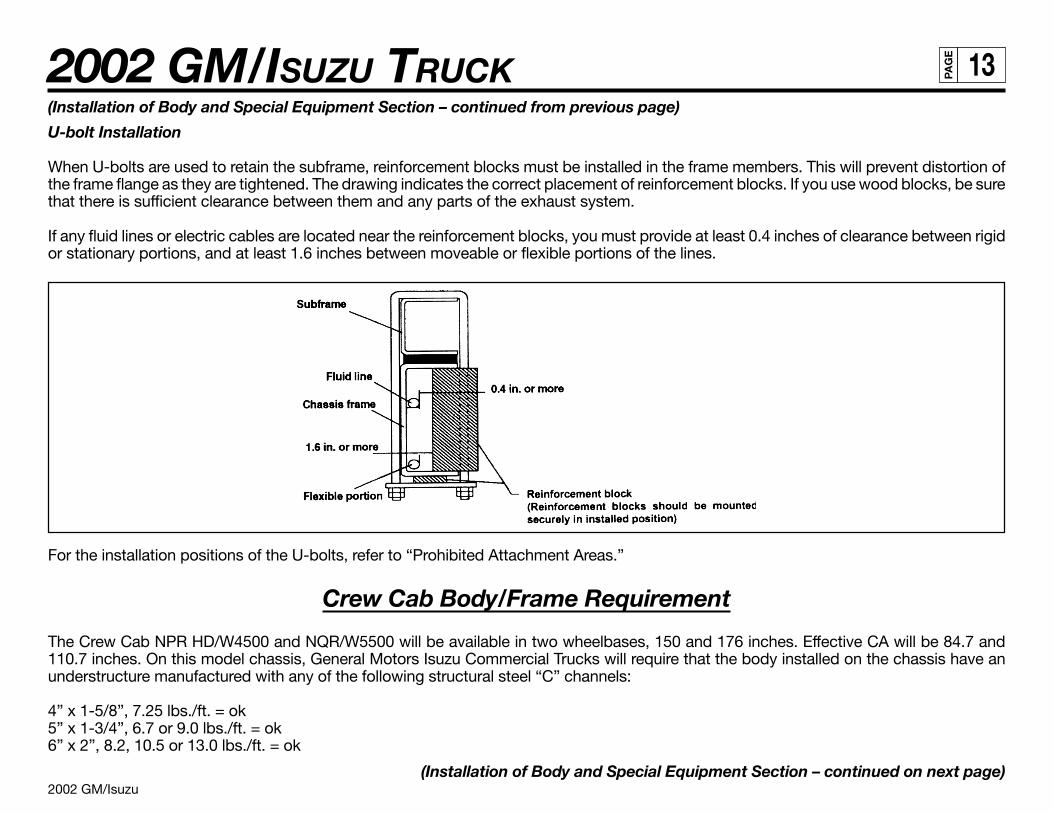
2002 GM/Isuzu
2002 GM/ISUZU TRUCK 13PA
GE
(Installation of Body and Special Equipment Section – continued from previous page)
U-bolt Installation
When U-bolts are used to retain the subframe, reinforcement blocks must be installed in the frame members. This will prevent distortion ofthe frame flange as they are tightened. The drawing indicates the correct placement of reinforcement blocks. If you use wood blocks, be surethat there is sufficient clearance between them and any parts of the exhaust system.
If any fluid lines or electric cables are located near the reinforcement blocks, you must provide at least 0.4 inches of clearance between rigidor stationary portions, and at least 1.6 inches between moveable or flexible portions of the lines.
For the installation positions of the U-bolts, refer to “Prohibited Attachment Areas.”
Crew Cab Body/Frame Requirement
The Crew Cab NPR HD/W4500 and NQR/W5500 will be available in two wheelbases, 150 and 176 inches. Effective CA will be 84.7 and110.7 inches. On this model chassis, General Motors Isuzu Commercial Trucks will require that the body installed on the chassis have anunderstructure manufactured with any of the following structural steel “C” channels:
4” x 1-5/8”, 7.25 lbs./ft. = ok5” x 1-3/4”, 6.7 or 9.0 lbs./ft. = ok6” x 2”, 8.2, 10.5 or 13.0 lbs./ft. = ok
(Installation of Body and Special Equipment Section – continued on next page)
2002 GM/Isuzu
2002 GM/ISUZU TRUCK 14PA
GE
(Installation of Body and Special Equipment Section – continued from previous page)
Modification of the Frame
Modifications of the chassis frame should be held to an absolute minimum. Modification work should be performed according to theinstructions in the following paragraphs.
When modification is complete, chassis frame members should be carefully inspected to eliminate the possibility of any safety-relateddefects.
NOTE: PLEASE REFER TO NOTES ON CHASSIS FRAME MODIFICATION WITH ANTILOCK BRAKES.
Working on Chassis frame
The chassis frame is designed and built with consideration for proper load distribution. Sufficient physical strength is provided when the loadis evenly distributed. Installation of special equipment on the chassis frame can cause variations in load distribution. If even distribution ofload is not kept in mind when the equipment is installed, localization of stresses on specific areas of the frame could cause cracking of thechassis frame members or other problems, even if the total weight of the equipment is within the design limit.
The chassis frame is designed as an integral unit. Therefore, we do not recommend cutting the chassis frame under any circumstances.
Drilling and Welding
IMPORTANT NOTE: For vehicles equipped with electronic or hydra-matic transmissions,electric arc welding must be done with the negative battery cable disconnected.
1. Do not drill or weld in the shaded portions of the chassis frame members. Do not weld within 0.8 inches from the edges of anyexisting holes.
2. Hold the length of any welding beads within 1.2-2.0 inches. Allow at least 1.6 inches between adjacent welding beads.
3. All holes must be drilled. Do not use a torch to make any holes.
4. All riveting must be done with cold rivets. Do not use hot rivets.
5. The flange of the chassis frame must not be cut under any circumstances.
6. The subframe must be attached to the chassis frame with bolts. Do not weld.
(Installation of Body and Special Equipment Section – continued on next page)
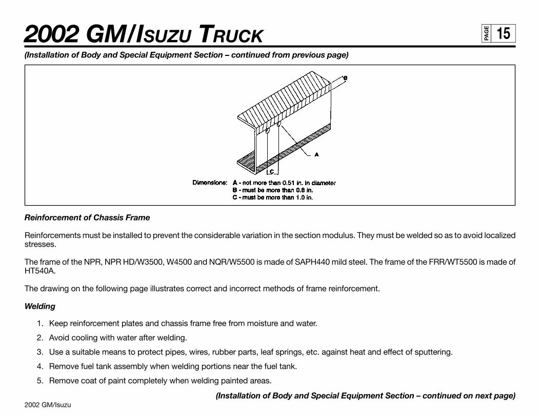
2002 GM/Isuzu
2002 GM/ISUZU TRUCK 15PA
GE
(Installation of Body and Special Equipment Section – continued from previous page)
Reinforcement of Chassis Frame
Reinforcements must be installed to prevent the considerable variation in the section modulus. They must be welded so as to avoid localizedstresses.
The frame of the NPR, NPR HD/W3500, W4500 and NQR/W5500 is made of SAPH440 mild steel. The frame of the FRR/WT5500 is made ofHT540A.
The drawing on the following page illustrates correct and incorrect methods of frame reinforcement.
Welding
1. Keep reinforcement plates and chassis frame free from moisture and water.
2. Avoid cooling with water after welding.
3. Use a suitable means to protect pipes, wires, rubber parts, leaf springs, etc. against heat and effect of sputtering.
4. Remove fuel tank assembly when welding portions near the fuel tank.
5. Remove coat of paint completely when welding painted areas.
(Installation of Body and Special Equipment Section – continued on next page)
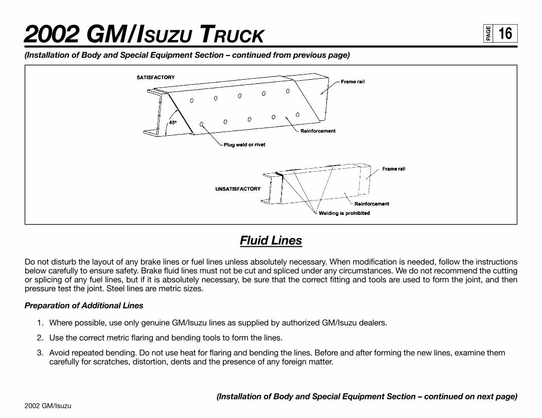
2002 GM/Isuzu
2002 GM/ISUZU TRUCK 16PA
GE
(Installation of Body and Special Equipment Section – continued from previous page)
Fluid Lines
Do not disturb the layout of any brake lines or fuel lines unless absolutely necessary. When modification is needed, follow the instructionsbelow carefully to ensure safety. Brake fluid lines must not be cut and spliced under any circumstances. We do not recommend the cuttingor splicing of any fuel lines, but if it is absolutely necessary, be sure that the correct fitting and tools are used to form the joint, and thenpressure test the joint. Steel lines are metric sizes.
Preparation of Additional Lines
1. Where possible, use only genuine GM/Isuzu lines as supplied by authorized GM/Isuzu dealers.
2. Use the correct metric flaring and bending tools to form the lines.
3. Avoid repeated bending. Do not use heat for flaring and bending the lines. Before and after forming the new lines, examine themcarefully for scratches, distortion, dents and the presence of any foreign matter.
(Installation of Body and Special Equipment Section – continued on next page)
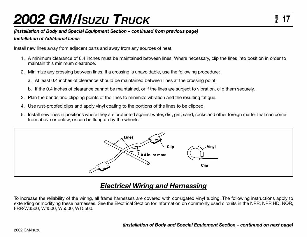
2002 GM/Isuzu
2002 GM/ISUZU TRUCK 17PA
GE
Electrical Wiring and Harnessing
To increase the reliability of the wiring, all frame harnesses are covered with corrugated vinyl tubing. The following instructions apply toextending or modifying these harnesses. See the Electrical Section for information on commonly used circuits in the NPR, NPR HD, NQR,FRR/W3500, W4500, W5500, WT5500.
(Installation of Body and Special Equipment Section – continued on next page)
(Installation of Body and Special Equipment Section – continued from previous page)
Installation of Additional Lines
Install new lines away from adjacent parts and away from any sources of heat.
1. A minimum clearance of 0.4 inches must be maintained between lines. Where necessary, clip the lines into position in order tomaintain this minimum clearance.
2. Minimize any crossing between lines. If a crossing is unavoidable, use the following procedure:
a. At least 0.4 inches of clearance should be maintained between lines at the crossing point.
b. If the 0.4 inches of clearance cannot be maintained, or if the lines are subject to vibration, clip them securely.
3. Plan the bends and clipping points of the lines to minimize vibration and the resulting fatigue.
4. Use rust-proofed clips and apply vinyl coating to the portions of the lines to be clipped.
5. Install new lines in positions where they are protected against water, dirt, grit, sand, rocks and other foreign matter that can comefrom above or below, or can be flung up by the wheels.
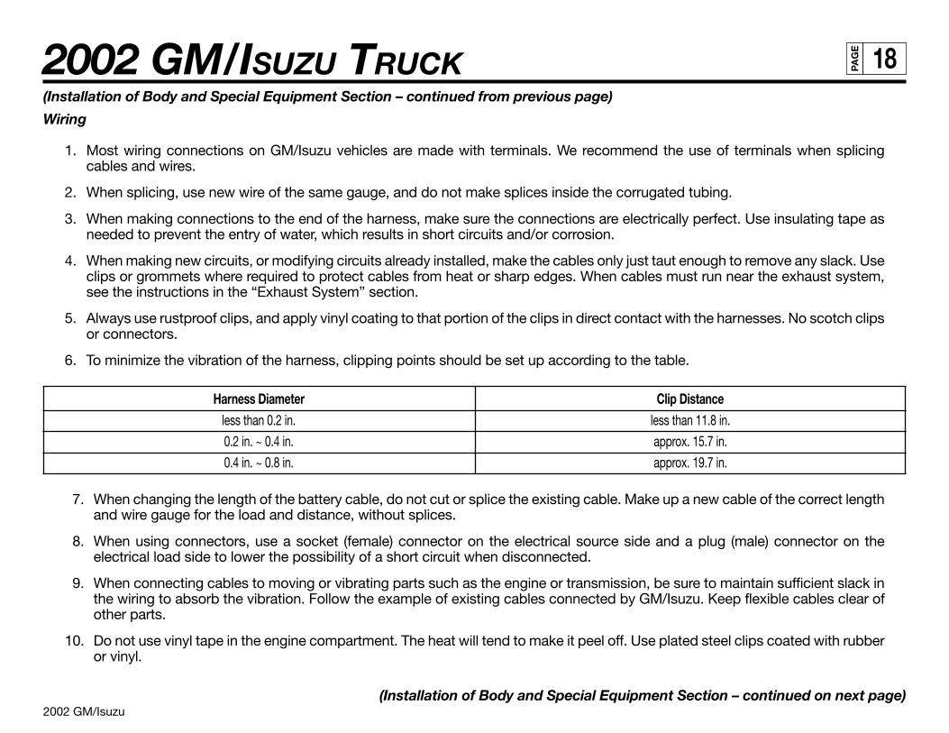
2002 GM/Isuzu
2002 GM/ISUZU TRUCK 18PA
GE
(Installation of Body and Special Equipment Section – continued from previous page)
Wiring
1. Most wiring connections on GM/Isuzu vehicles are made with terminals. We recommend the use of terminals when splicingcables and wires.
2. When splicing, use new wire of the same gauge, and do not make splices inside the corrugated tubing.
3. When making connections to the end of the harness, make sure the connections are electrically perfect. Use insulating tape asneeded to prevent the entry of water, which results in short circuits and/or corrosion.
4. When making new circuits, or modifying circuits already installed, make the cables only just taut enough to remove any slack. Useclips or grommets where required to protect cables from heat or sharp edges. When cables must run near the exhaust system,see the instructions in the “Exhaust System” section.
5. Always use rustproof clips, and apply vinyl coating to that portion of the clips in direct contact with the harnesses. No scotch clipsor connectors.
6. To minimize the vibration of the harness, clipping points should be set up according to the table.
Harness Diameter Clip Distanceless than 0.2 in. less than 11.8 in.
0.2 in. ~ 0.4 in. approx. 15.7 in.
0.4 in. ~ 0.8 in. approx. 19.7 in.
7. When changing the length of the battery cable, do not cut or splice the existing cable. Make up a new cable of the correct lengthand wire gauge for the load and distance, without splices.
8. When using connectors, use a socket (female) connector on the electrical source side and a plug (male) connector on theelectrical load side to lower the possibility of a short circuit when disconnected.
9. When connecting cables to moving or vibrating parts such as the engine or transmission, be sure to maintain sufficient slack inthe wiring to absorb the vibration. Follow the example of existing cables connected by GM/Isuzu. Keep flexible cables clear ofother parts.
10. Do not use vinyl tape in the engine compartment. The heat will tend to make it peel off. Use plated steel clips coated with rubberor vinyl.
(Installation of Body and Special Equipment Section – continued on next page)
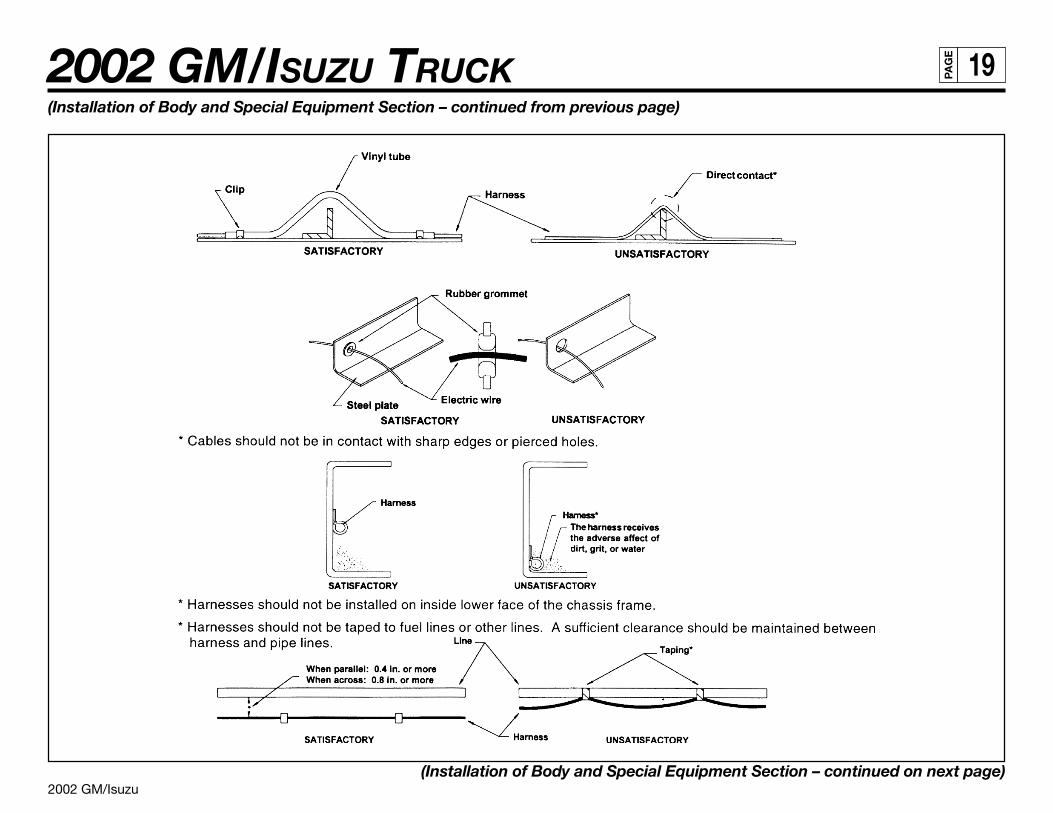
2002 GM/Isuzu
2002 GM/ISUZU TRUCK 19PA
GE
(Installation of Body and Special Equipment Section – continued from previous page)
(Installation of Body and Special Equipment Section – continued on next page)
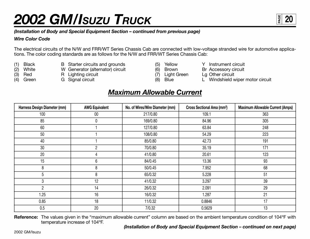
2002 GM/Isuzu
2002 GM/ISUZU TRUCK 20PA
GE
(Installation of Body and Special Equipment Section – continued from previous page)
Wire Color Code
The electrical circuits of the N/W and FRR/WT Series Chassis Cab are connected with low-voltage stranded wire for automotive applica-tions. The color coding standards are as follows for the N/W and FRR/WT Series Chassis Cab:
(1) Black B Starter circuits and grounds (5) Yellow Y Instrument circuit(2) White W Generator (alternator) circuit (6) Brown Br Accessory circuit(3) Red R Lighting circuit (7) Light Green Lg Other circuit(4) Green G Signal circuit (8) Blue L Windshield wiper motor circuit
Maximum Allowable Current
Harness Design Diameter (mm) AWG Equivalent No. of Wires/Wire Diameter (mm) Cross Sectional Area (mm2) Maximum Allowable Current (Amps)100 00 217/0.80 109.1 36385 0 169/0.80 84.96 30560 1 127/0.80 63.84 24850 1 108/0.80 54.29 22340 1 85/0.80 42.73 19130 2 70/0.80 35.19 17120 4 41/0.80 20.61 12315 6 84/0.45 13.36 93 8 8 50/0.45 7.952 68 5 8 65/0.32 5.228 51 3 12 41/0.32 3.297 39 2 14 26/0.32 2.091 29
1.25 16 16/0.32 1.287 210.85 18 11/0.32 0.8846 170.5 20 7/0.32 0.5629 13
Reference: The values given in the “maximum allowable current” column are based on the ambient temperature condition of 104ºF withtemperature increase of 104ºF.
(Installation of Body and Special Equipment Section – continued on next page)
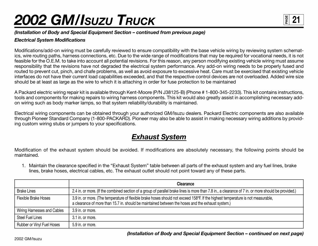
2002 GM/Isuzu
2002 GM/ISUZU TRUCK 21PA
GE
(Installation of Body and Special Equipment Section – continued from previous page)
Electrical System Modifications
Modifications/add-on wiring must be carefully reviewed to ensure compatibility with the base vehicle wiring by reviewing system schemat-ics, wire routing paths, harness connections, etc. Due to the wide range of modifications that may be required for vocational needs, it is notfeasible for the O.E.M. to take into account all potential revisions. For this reason, any person modifying existing vehicle wiring must assumeresponsibility that the revisions have not degraded the electrical system performance. Any add-on wiring needs to be properly fused androuted to prevent cut, pinch, and chafe problems, as well as avoid exposure to excessive heat. Care must be exercised that existing vehicleinterfaces do not have their current load capabilities exceeded, and that the respective control devices are not overloaded. Added wire sizeshould be at least as large as the wire to which it is attaching in order for fuse protection to be maintained
A Packard electric wiring repair kit is available through Kent-Moore (P/N J38125-B) (Phone # 1-800-345-2233). This kit contains instructions,tools and components for making repairs to wiring harness components. This kit would also greatly assist in accomplishing necessary add-on wiring such as body marker lamps, so that system reliability/durability is maintained.
Electrical wiring components can be obtained through your authorized GM/Isuzu dealers. Packard Electric components are also availablethrough Pioneer Standard Company (1-800-PACKARD). Pioneer may also be able to assist in making necessary wiring additions by provid-ing custom wiring stubs or jumpers to your specifications.
Exhaust System
Modification of the exhaust system should be avoided. If modifications are absolutely necessary, the following points should bemaintained.
1. Maintain the clearance specified in the “Exhaust System” table between all parts of the exhaust system and any fuel lines, brakelines, brake hoses, electrical cables, etc. The exhaust outlet should not point toward any of these parts.
ClearanceBrake Lines 2.4 in. or more. (If the combined section of a group of parallel brake lines is more than 7.8 in., a clearance of 7 in. or more should be provided.)
Flexible Brake Hoses 3.9 in. or more. (The temperature of flexible brake hoses should not exceed 158ºF. If the highest temperature is not measurable,a clearance of more than 15.7 in. should be maintained between the hoses and the exhaust system.)
Wiring Harnesses and Cables 3.9 in. or more.
Steel Fuel Lines 3.1 in. or more.
Rubber or Vinyl Fuel Hoses 5.9 in. or more.
(Installation of Body and Special Equipment Section – continued on next page)
2002 GM/Isuzu
2002 GM/ISUZU TRUCK 22PA
GE
(Installation of Body and Special Equipment Section – continued from previous page)
2. If a tool box is installed, it should preferably be made from steel. If a wooden tool box is installed, at least 7.8 inches of clearanceshould be maintained between the tool box and any parts of the exhaust system.
3. If the exhaust system is modified, it is the responsibility of those making the modification to ensure that the noise level meetsappropriate standards.
Fuel System
Relocation of the fuel tank, or installation of additional fuel tanks, is not recommended. If modifications to the fuel system are unavoidable,follow these recommendations:
1. Maintain adequate clearance between the fuel tank and any other device or structure.
2. Do not connect any additional fuel hose.
Rear Lighting
Brackets installed are temporary. Please do not use these brackets for body installation.
Serviceability
No matter what other modifications or changes are made, access to components requiring daily preventive maintenance or other routineservice must not be obstructed. This includes:
1. Inspection, filling and draining of engine oil and cooling water.
2. Inspection, filling and draining of transmission fluid.
3. Adjustment, removal and installation of the fan belts.
4. Inspection, filling and removal of the battery and battery cover.
5. Inspection and filling of brake fluid.
6. Inspection and bleeding of the brake system and servo unit.
7. Maintenance of clearance for tightening of check bolt on brake safety cylinder.
8. Operation of the spare tire carrier, including mounting and dismounting of the spare tire.
9. Adjustment, removal and installation of distributor and/or cover.(Installation of Body and Special Equipment Section – continued on next page)
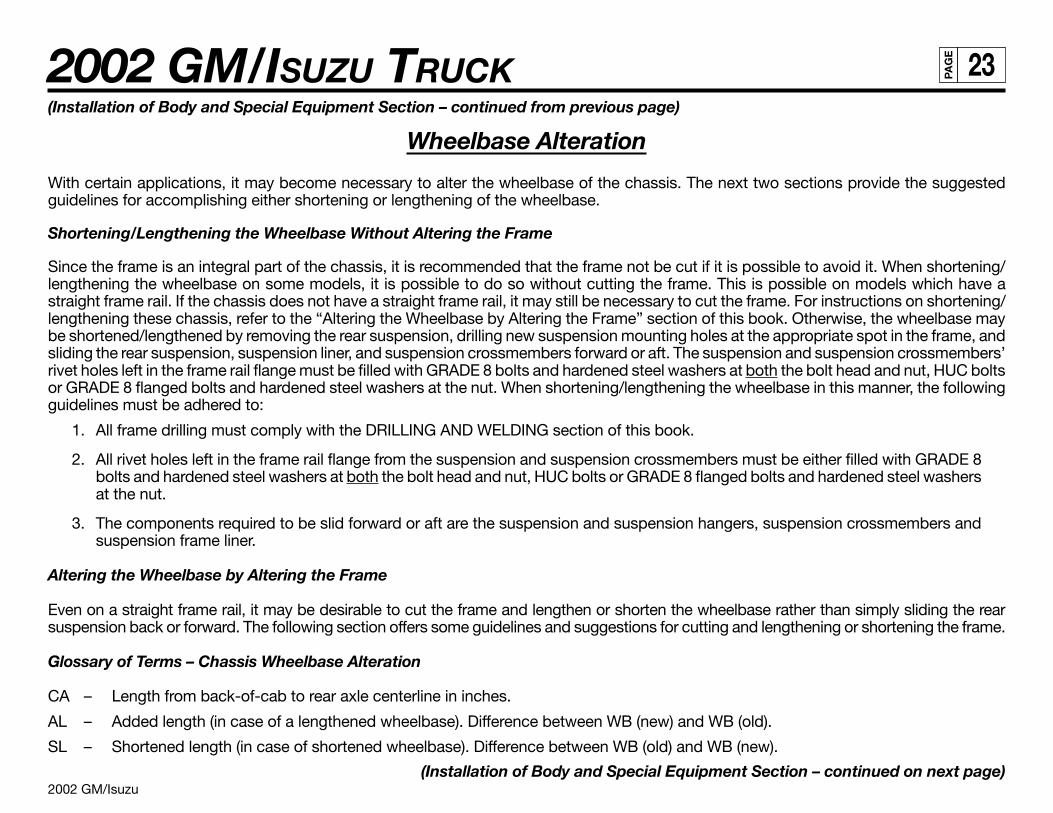
2002 GM/Isuzu
2002 GM/ISUZU TRUCK 23PA
GE
(Installation of Body and Special Equipment Section – continued from previous page)
Wheelbase Alteration
With certain applications, it may become necessary to alter the wheelbase of the chassis. The next two sections provide the suggestedguidelines for accomplishing either shortening or lengthening of the wheelbase.
Shortening/Lengthening the Wheelbase Without Altering the Frame
Since the frame is an integral part of the chassis, it is recommended that the frame not be cut if it is possible to avoid it. When shortening/lengthening the wheelbase on some models, it is possible to do so without cutting the frame. This is possible on models which have astraight frame rail. If the chassis does not have a straight frame rail, it may still be necessary to cut the frame. For instructions on shortening/lengthening these chassis, refer to the “Altering the Wheelbase by Altering the Frame” section of this book. Otherwise, the wheelbase maybe shortened/lengthened by removing the rear suspension, drilling new suspension mounting holes at the appropriate spot in the frame, andsliding the rear suspension, suspension liner, and suspension crossmembers forward or aft. The suspension and suspension crossmembers’rivet holes left in the frame rail flange must be filled with GRADE 8 bolts and hardened steel washers at both the bolt head and nut, HUC boltsor GRADE 8 flanged bolts and hardened steel washers at the nut. When shortening/lengthening the wheelbase in this manner, the followingguidelines must be adhered to:
1. All frame drilling must comply with the DRILLING AND WELDING section of this book.
2. All rivet holes left in the frame rail flange from the suspension and suspension crossmembers must be either filled with GRADE 8bolts and hardened steel washers at both the bolt head and nut, HUC bolts or GRADE 8 flanged bolts and hardened steel washersat the nut.
3. The components required to be slid forward or aft are the suspension and suspension hangers, suspension crossmembers andsuspension frame liner.
Altering the Wheelbase by Altering the Frame
Even on a straight frame rail, it may be desirable to cut the frame and lengthen or shorten the wheelbase rather than simply sliding the rearsuspension back or forward. The following section offers some guidelines and suggestions for cutting and lengthening or shortening the frame.
Glossary of Terms – Chassis Wheelbase Alteration
CA – Length from back-of-cab to rear axle centerline in inches.
AL – Added length (in case of a lengthened wheelbase). Difference between WB (new) and WB (old).
SL – Shortened length (in case of shortened wheelbase). Difference between WB (old) and WB (new).
(Installation of Body and Special Equipment Section – continued on next page)
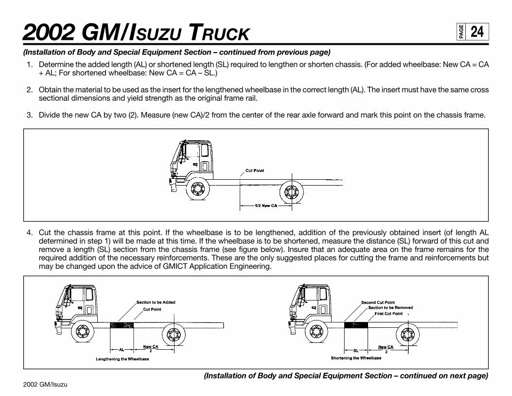
2002 GM/Isuzu
2002 GM/ISUZU TRUCK 24PA
GE
(Installation of Body and Special Equipment Section – continued from previous page)
1. Determine the added length (AL) or shortened length (SL) required to lengthen or shorten chassis. (For added wheelbase: New CA = CA+ AL; For shortened wheelbase: New CA = CA – SL.)
2. Obtain the material to be used as the insert for the lengthened wheelbase in the correct length (AL). The insert must have the same crosssectional dimensions and yield strength as the original frame rail.
3. Divide the new CA by two (2). Measure (new CA)/2 from the center of the rear axle forward and mark this point on the chassis frame.
4. Cut the chassis frame at this point. If the wheelbase is to be lengthened, addition of the previously obtained insert (of length ALdetermined in step 1) will be made at this time. If the wheelbase is to be shortened, measure the distance (SL) forward of this cut andremove a length (SL) section from the chassis frame (see figure below). Insure that an adequate area on the frame remains for therequired addition of the necessary reinforcements. These are the only suggested places for cutting the frame and reinforcements butmay be changed upon the advice of GMICT Application Engineering.
(Installation of Body and Special Equipment Section – continued on next page)
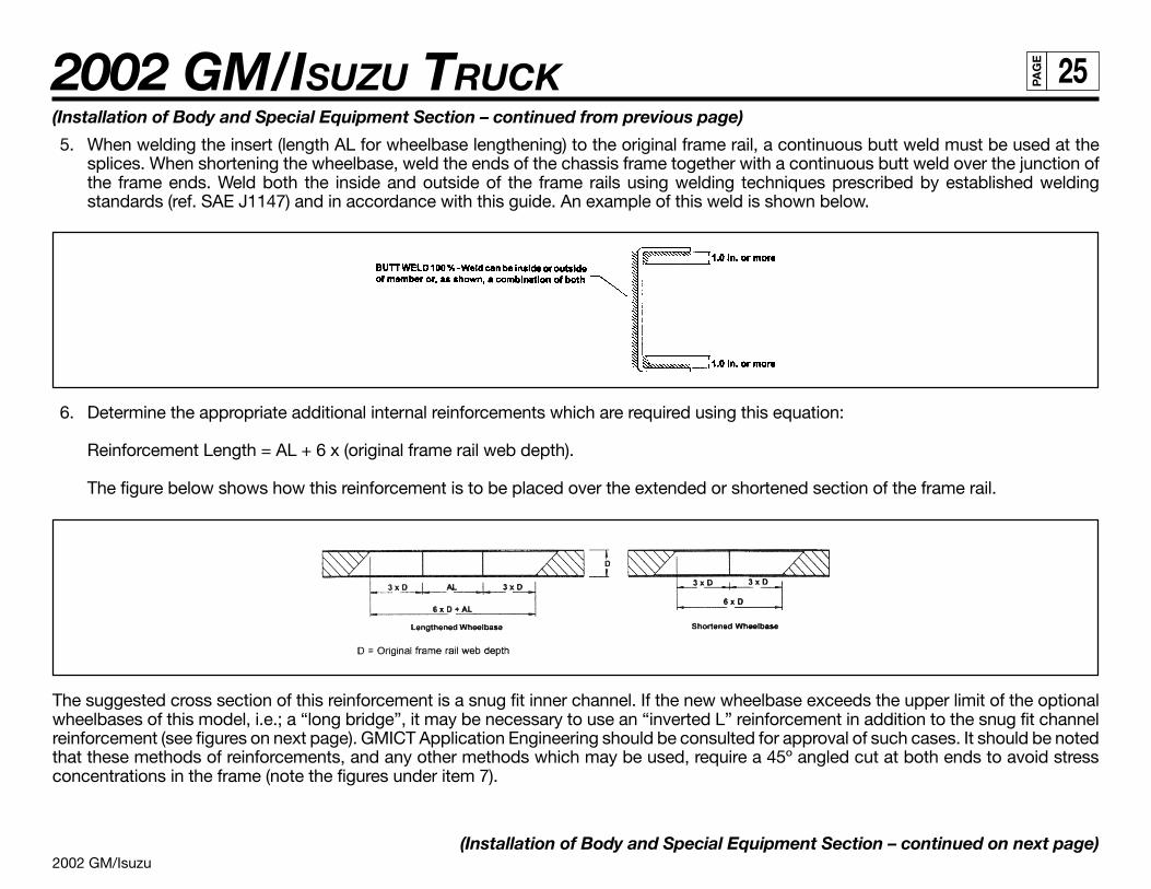
2002 GM/Isuzu
2002 GM/ISUZU TRUCK 25PA
GE
6. Determine the appropriate additional internal reinforcements which are required using this equation:
Reinforcement Length = AL + 6 x (original frame rail web depth).
The figure below shows how this reinforcement is to be placed over the extended or shortened section of the frame rail.
(Installation of Body and Special Equipment Section – continued from previous page)
5. When welding the insert (length AL for wheelbase lengthening) to the original frame rail, a continuous butt weld must be used at thesplices. When shortening the wheelbase, weld the ends of the chassis frame together with a continuous butt weld over the junction ofthe frame ends. Weld both the inside and outside of the frame rails using welding techniques prescribed by established weldingstandards (ref. SAE J1147) and in accordance with this guide. An example of this weld is shown below.
The suggested cross section of this reinforcement is a snug fit inner channel. If the new wheelbase exceeds the upper limit of the optionalwheelbases of this model, i.e.; a “long bridge”, it may be necessary to use an “inverted L” reinforcement in addition to the snug fit channelreinforcement (see figures on next page). GMICT Application Engineering should be consulted for approval of such cases. It should be notedthat these methods of reinforcements, and any other methods which may be used, require a 45º angled cut at both ends to avoid stressconcentrations in the frame (note the figures under item 7).
(Installation of Body and Special Equipment Section – continued on next page)
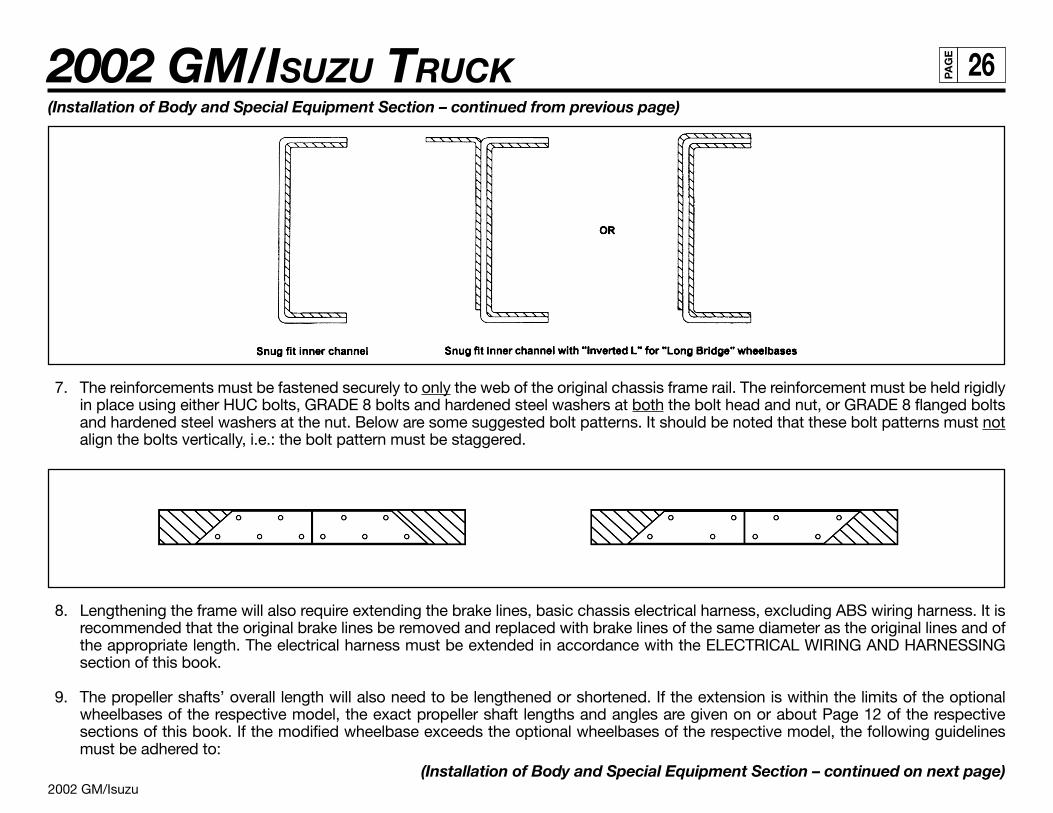
2002 GM/Isuzu
2002 GM/ISUZU TRUCK 26PA
GE
(Installation of Body and Special Equipment Section – continued from previous page)
7. The reinforcements must be fastened securely to only the web of the original chassis frame rail. The reinforcement must be held rigidlyin place using either HUC bolts, GRADE 8 bolts and hardened steel washers at both the bolt head and nut, or GRADE 8 flanged boltsand hardened steel washers at the nut. Below are some suggested bolt patterns. It should be noted that these bolt patterns must notalign the bolts vertically, i.e.: the bolt pattern must be staggered.
8. Lengthening the frame will also require extending the brake lines, basic chassis electrical harness, excluding ABS wiring harness. It isrecommended that the original brake lines be removed and replaced with brake lines of the same diameter as the original lines and ofthe appropriate length. The electrical harness must be extended in accordance with the ELECTRICAL WIRING AND HARNESSINGsection of this book.
9. The propeller shafts’ overall length will also need to be lengthened or shortened. If the extension is within the limits of the optionalwheelbases of the respective model, the exact propeller shaft lengths and angles are given on or about Page 12 of the respectivesections of this book. If the modified wheelbase exceeds the optional wheelbases of the respective model, the following guidelinesmust be adhered to:
(Installation of Body and Special Equipment Section – continued on next page)
2002 GM/Isuzu
2002 GM/ISUZU TRUCK 27PA
GE
(Installation of Body and Special Equipment Section – continued from previous page)
a. Propeller Shaft Length
The maximum propeller shaft lengths (pin to pin) for the respective models are shown in the table below.
NPR/W3500, W4500 Diesel NPR/W3500, W4500 Gas NQR/W5500 FRR/WT5500Propeller Shaft Diameter (in.) 3.25 3.0 3.0 4.0
Maximum Propeller Shaft Length (in.) 50.8 50.8 50.8 62.0
b. Propeller Shaft Angles
The maximum propeller shaft angles, with respect to the previous shaft, are shown in the table below.
NPR/W3500, W4500 Diesel NPR/W3500, W4500 Gas NQR/W5500 FRR/WT5500Maximum Propeller Shaft Angle 5.7º 5.1º 5.7º 5.5º
c. The propeller shaft angles must be designed such that the angles will cancel to avoid propeller shaft whip.
d. The propeller shaft yokes must be assembled such that the propeller shaft yokes are “in phase.” “In phase” means that the yokes ateither end of a given propeller shaft assembly are in the same plane.
10. Extending the frame will also require relocation and/or addition of crossmembers. If the extension is within the limits of the optionalwheelbases of the respective model, the exact crossmember locations and dimensions are given in the respective model sections ofthis book. If the modified wheelbase exceeds the optional wheelbases of the respective model, the following guidelines must beadhered to:
a. The crossmember location will largely be determined by the propeller shaft lengths and where the center carrier bearing locations arefor the propeller shaft assembly.
b. A crossmember must be located at the front and rear spring hangers of the rear suspension (refer to the appropriate section of thisbook to see where these suspension crossmembers are to be located).
c. The crossmember must be constructed such that it supports both the upper and lower flange on each frame rail (see drawing on nextpage). A crossmember such as the one on the next page may be constructed, or GM/Isuzu crossmembers may be obtained fromyour GMICT parts dealer.
(Installation of Body and Special Equipment Section – continued on next page)
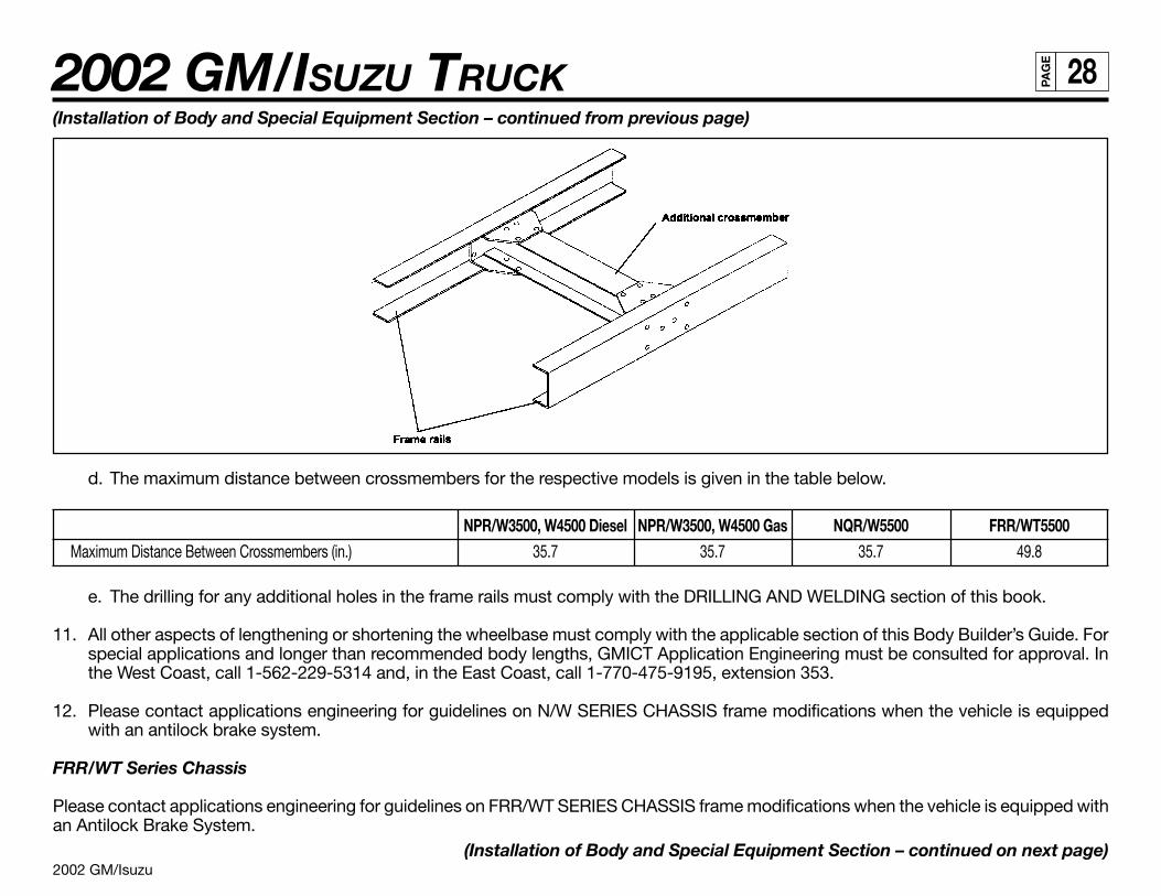
2002 GM/Isuzu
2002 GM/ISUZU TRUCK 28PA
GE
(Installation of Body and Special Equipment Section – continued from previous page)
d. The maximum distance between crossmembers for the respective models is given in the table below.
NPR/W3500, W4500 Diesel NPR/W3500, W4500 Gas NQR/W5500 FRR/WT5500Maximum Distance Between Crossmembers (in.) 35.7 35.7 35.7 49.8
e. The drilling for any additional holes in the frame rails must comply with the DRILLING AND WELDING section of this book.
11. All other aspects of lengthening or shortening the wheelbase must comply with the applicable section of this Body Builder’s Guide. Forspecial applications and longer than recommended body lengths, GMICT Application Engineering must be consulted for approval. Inthe West Coast, call 1-562-229-5314 and, in the East Coast, call 1-770-475-9195, extension 353.
12. Please contact applications engineering for guidelines on N/W SERIES CHASSIS frame modifications when the vehicle is equippedwith an antilock brake system.
FRR/WT Series Chassis
Please contact applications engineering for guidelines on FRR/WT SERIES CHASSIS frame modifications when the vehicle is equipped withan Antilock Brake System.
(Installation of Body and Special Equipment Section – continued on next page)
2002 GM/Isuzu
2002 GM/ISUZU TRUCK 29PA
GE
(Installation of Body and Special Equipment Section – continued from previous page)
13. The Crew Cab NPR HD/W4500 and NQR/W5500 will be available in two wheelbases, 150 and 176 inches. Effective CA will be 84.7 and110.7 inches. On this model chassis, General Motors Isuzu Commercial Trucks will require that the body installed on the chassis havean understructure manufactured with any of the following structural steel “C” channels:
4" x 1-5/8", 7.25 lbs./ft. = ok
5" x 1-3/4", 6.7 or 9.0 lbs./ft. = ok
6" x 2", 8.2, 10.5 or 13.0 lbs./ft. = ok
Hydraulic Brake System
Before Work Begins
As with any electrical work on the chassis, the battery should be disconnected before electrical work is started.
ABS Program
The antilock brake system (ABS) computer will hold its codes when disconnected and reprogramming as a result of battery disconnectionwill not be necessary. If the wheelbase is changed, the trim level of the ABS system must be readjusted per the instructions in the servicemanual. An authorized GM/Isuzu dealer should do this reprogramming using appropriate tools.
For your reference, and to help you determine if the system needs to be reprogrammed, the following provisions apply to all ABS systemswith hydraulic brakes. The ABS module has four (4) programs: A, B, C and D. These programs are tied to the wheelbase and axle combina-tion of the chassis. (The axle and wheelbase codes can be found on the passenger’s visor.)
A is for the FL1 axle and covers wheelbase from 140 (FQT), 158 (EG5), and 170 (EH8) inches.
B is for the FL2 axle and covers wheelbase from 140 (FQT), 158 (EG5), 170 (EH8), 188 (EK8), and 200 (EM2) inches.
C is for the FL1 axle and covers wheelbase from 188 (EK8), 200 (EM2), 218 (FPL), 233 (EQ8), and 248 (ES5) inches.
D is for the FL2 axle and covers wheelbase from 218 (FPL), 233 (EQ8), and 248 (ES5) inches.
Moving between program/wheelbase groups A, B, C or D will require that the system be reprogrammed. Moving wheelbase within aprogram group will not require reprogramming.
(Installation of Body and Special Equipment Section – continued on next page)
2002 GM/Isuzu
2002 GM/ISUZU TRUCK 30PA
GE
(Installation of Body and Special Equipment Section – continued from previous page)
ABS Computer Location
a. The ABS computer is located under the cab on the front crossmember and is an integral part of the brake fluid modulation system.These components cannot be relocated.
ABS Electrical Harness
a. The harness cannot be cut and spliced.
b. The only approved way to make the harness longer is to purchase the appropriate wheelbase harness from the GM/Isuzu partsdepartment.
c. Extra wire resulting from a frame shortening can be coiled and secured to the frame.
Hydraulic Brake Lines
a. Hydraulic brake lines should be shortened or lengthened using appropriate fitting and steel lines.
2002 GM/Isuzu
2002 GM/ISUZU TRUCK 31PA
GE
BODY APPLICATION SUMMARY CHART
2002 Model Year Body Application Summary Chart
Model/GVWR WB BOC 10 ft. 12 ft. 14 ft. 16 ft. 18 ft. 20 ft. 22 ft. 24 ft.109 9.25 X X
NPR/W3500 Gas 132.5 9.25 X12,000 lbs. 150 9.25 X X
176 9.25 X1
109 9.25 X XNPR HD/W4500 Gas 132.5 9.25 X
14,050 lbs. 150 9.25 X X176 9.25 X1
109 9.25 XNPR/W3500 Diesel 132.5 9.25 X
12,000 lbs. 150 9.25 X X176 9.25 X1
109 9.25 XNPR HD/W4500 Diesel 132.5 9.25 X
14,500 lbs. 150 9.25 X X176 9.25 X1
NPR HD/W4500 Crew Cab Diesel 150 4.2 X4
14,500 lbs. 176 4.2 X5
109 9.25 XNQR/W5500 Diesel 132.5 9.25 X
17,950 lbs. 150 9.25 X X176 9.25 X X2
(2002 Model Year Body Application Summary Chart continued on next page)1 = NPR, NPR HD/W3500, W4500 and Diesel 20-foot body requires GMICT Application Engineering Department approval.2 = NQR/W5500 22-foot body requires GMICT Application Engineering Department approval.3 = BOC 10.0 inches for MT.4 = 16' Dovetail landscape (12' deck plus 4' dovetail).5 = 18' Dovetail landscape (14' deck plus 4' dovetail).IMPORTANT: Body selection recommendations are based on water-level weight distribution and no accessories, liftgate or refrigeration units. This table is intended
for reference and does not preclude the necessity for an accurate weight distribution calculation.
(Body Application Summary Chart Section – continued on next page)
2002 GM/Isuzu
2002 GM/ISUZU TRUCK 32PA
GE
(Body Application Summary Chart Section – continued from previous page)
2002 Model Year Body Application Summary Chart (Chart continued from previous page)
Model/GVWR WB BOC 10 ft. 12 ft. 14 ft. 16 ft. 18 ft. 20 ft. 22 ft. 24 ft.NQR/W5500 Crew Cab Diesel 150 4.2 X4
17,950 lbs. 176 4.2 X5
MT/AT148 7.5/10 X3 X
FRR/WT5500 Diesel 167 7.5/10 X 18,000/19,500 lbs. 179 7.5/10 X
191 7.5/10 X218 10.0/10 X
1 = NPR, NPR HD/W3500, W4500 and Diesel 20-foot body requires GMICT Application Engineering Department approval.2 = NQR/W5500 22-foot body requires GMICT Application Engineering Department approval.3 = BOC 10.0 inches for MT.4 = 16' Dovetail landscape (12' deck plus 4' dovetail).5 = 18' Dovetail landscape (14' deck plus 4' dovetail).IMPORTANT: Body selection recommendations are based on water-level weight distribution and no accessories, liftgate or refrigeration units. This table is intended
for reference and does not preclude the necessity for an accurate weight distribution calculation.
(Body Application Summary Chart Section – continued on next page)
2002 GM/Isuzu
2002 GM/ISUZU TRUCK 33PA
GE
(Body Application Summary Chart Section – continued from previous page)
NPR, NPR HD/W3500, W4500 Gas
2002 Model Year – Body & Payload Weight Distribution (% Front/% Rear) – Automatic Transmission
Model GVWR WB CA CE OAL BOC 10 ft. 12 ft. 14 ft. 16 ft. 18 ft. 20 ft.NPR/W3500 Gas 12,000 109 88.4 131.5 199.5 9.25 18/82 7/93
NPR HD/W4500 Gas 14,050 109 88.4 131.5 199.5 9.25 18/82 7/93
NPR/W3500 Gas 12,000 132.5 111.9 155 223 9.25 14/86
NPR HD/W4500 Gas 14,050 132.5 111.9 155 223 9.25 14/86
NPR/W3500 Gas 12,000 150 129.4 172.5 240.5 9.25 16/84 8/92
NPR HD/W4500 Gas 14,050 150 129.4 172.5 240.5 9.25 16/84 8/92
NPR/W3500 Gas 12,000 176 155.4 198.5 266.3 9.25 15/85*
NPR HD/W4500 Gas 14,050 176 155.4 198.5 266.3 9.25 15/85*
(Body Application Summary Chart Section – continued on next page)
2002 GM/Isuzu
2002 GM/ISUZU TRUCK 34PA
GE
(Body Application Summary Chart – continued from previous page)
NPR, NPR HD/W3500, W4500 Diesel
2002 Model Year – Body & Payload Weight Distribution (% Front/% Rear) – Manual/Automatic Transmission
Model GVWR WB CA CE OAL BOC 10 ft. 12 ft. 14 ft. 16 ft. 18 ft. 20 ft.NPR/W3500 Diesel 12,000 109 88.4 131.5 199.5 9.25 7/93
NPR HD/W4500 Diesel 14,050 109 88.4 131.5 199.5 9.25 7/93
NPR/W3500 Diesel 12,000 132.5 111.9 155 223 9.25 14/86
NPR HD/W4500 Diesel 14,050 132.5 111.9 155 223 9.25 14/86
NPR/W3500 Diesel 12,000 150 129.4 172.5 240.5 9.25 16/84 8/92
NPR HD/W4500 Diesel 14,050 150 129.4 172.5 240.5 9.25 16/84 8/92
NPR/W3500 Diesel 12,000 176 155.4 198.5 266.3 9.25 15/85*
NPR HD/W4500 Diesel 14,050 176 155.4 198.5 266.3 9.25 15/85*
(Body Application Summary Chart Section – continued on next page)
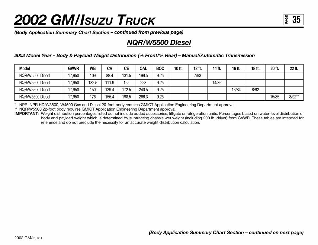
2002 GM/Isuzu
2002 GM/ISUZU TRUCK 35PA
GE
(Body Application Summary Chart Section – continued from previous page)
NQR/W5500 Diesel
2002 Model Year – Body & Payload Weight Distribution (% Front/% Rear) – Manual/Automatic Transmission
Model GVWR WB CA CE OAL BOC 10 ft. 12 ft. 14 ft. 16 ft. 18 ft. 20 ft. 22 ft.NQR/W5500 Diesel 17,950 109 88.4 131.5 199.5 9.25 7/93
NQR/W5500 Diesel 17,950 132.5 111.9 155 223 9.25 14/86
NQR/W5500 Diesel 17,950 150 129.4 172.5 240.5 9.25 16/84 8/92
NQR/W5500 Diesel 17,950 176 155.4 198.5 266.3 9.25 15/85 8/92**
* NPR, NPR HD/W3500, W4500 Gas and Diesel 20-foot body requires GMICT Application Engineering Department approval.** NQR/W5500 22-foot body requires GMICT Application Engineering Department approval.IMPORTANT: Weight distribution percentages listed do not include added accessories, liftgate or refrigeration units. Percentages based on water-level distribution of
body and payload weight which is determined by subtracting chassis wet weight (including 200 lb. driver) from GVWR. These tables are intended forreference and do not preclude the necessity for an accurate weight distribution calculation.
(Body Application Summary Chart Section – continued on next page)
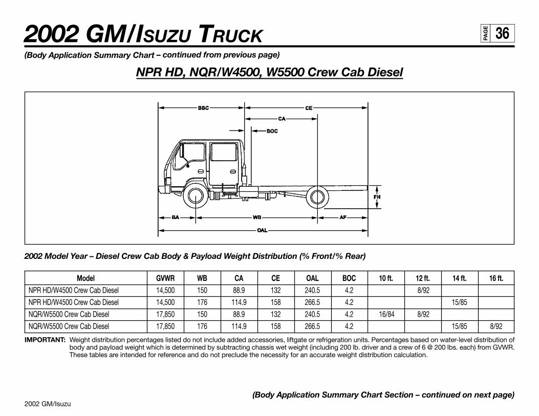
2002 GM/Isuzu
2002 GM/ISUZU TRUCK 36PA
GE
2002 Model Year – Diesel Crew Cab Body & Payload Weight Distribution (% Front/% Rear)
Model GVWR WB CA CE OAL BOC 10 ft. 12 ft. 14 ft. 16 ft.NPR HD/W4500 Crew Cab Diesel 14,500 150 88.9 132 240.5 4.2 8/92
NPR HD/W4500 Crew Cab Diesel 14,500 176 114.9 158 266.5 4.2 15/85
NQR/W5500 Crew Cab Diesel 17,850 150 88.9 132 240.5 4.2 16/84 8/92
NQR/W5500 Crew Cab Diesel 17,850 176 114.9 158 266.5 4.2 15/85 8/92
IMPORTANT: Weight distribution percentages listed do not include added accessories, liftgate or refrigeration units. Percentages based on water-level distribution ofbody and payload weight which is determined by subtracting chassis wet weight (including 200 lb. driver and a crew of 6 @ 200 lbs. each) from GVWR.These tables are intended for reference and do not preclude the necessity for an accurate weight distribution calculation.
(Body Application Summary Chart Section – continued on next page)
(Body Application Summary Chart – continued from previous page)
NPR HD, NQR/W4500, W5500 Crew Cab Diesel
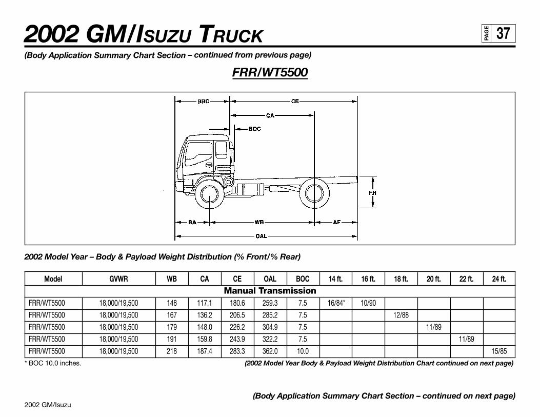
2002 GM/Isuzu
2002 GM/ISUZU TRUCK 37PA
GE
(Body Application Summary Chart Section – continued from previous page)
FRR/WT5500
2002 Model Year – Body & Payload Weight Distribution (% Front/% Rear)
Model GVWR WB CA CE OAL BOC 14 ft. 16 ft. 18 ft. 20 ft. 22 ft. 24 ft.Manual Transmission
FRR/WT5500 18,000/19,500 148 117.1 180.6 259.3 7.5 16/84* 10/90
FRR/WT5500 18,000/19,500 167 136.2 206.5 285.2 7.5 12/88
FRR/WT5500 18,000/19,500 179 148.0 226.2 304.9 7.5 11/89
FRR/WT5500 18,000/19,500 191 159.8 243.9 322.2 7.5 11/89
FRR/WT5500 18,000/19,500 218 187.4 283.3 362.0 10.0 15/85* BOC 10.0 inches. (2002 Model Year Body & Payload Weight Distribution Chart continued on next page)
(Body Application Summary Chart Section – continued on next page)
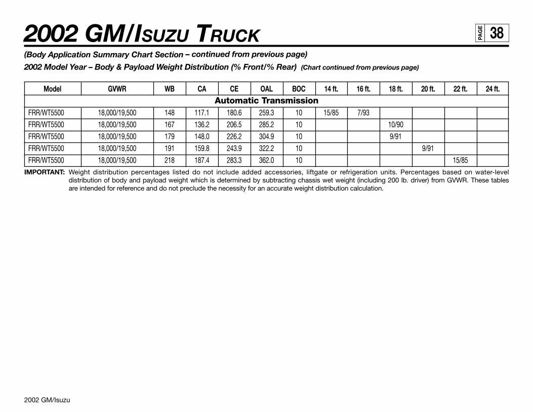
2002 GM/Isuzu
2002 GM/ISUZU TRUCK 38PA
GE
(Body Application Summary Chart Section – continued from previous page)
2002 Model Year – Body & Payload Weight Distribution (% Front/% Rear) (Chart continued from previous page)
Model GVWR WB CA CE OAL BOC 14 ft. 16 ft. 18 ft. 20 ft. 22 ft. 24 ft.Automatic Transmission
FRR/WT5500 18,000/19,500 148 117.1 180.6 259.3 10 15/85 7/93
FRR/WT5500 18,000/19,500 167 136.2 206.5 285.2 10 10/90
FRR/WT5500 18,000/19,500 179 148.0 226.2 304.9 10 9/91
FRR/WT5500 18,000/19,500 191 159.8 243.9 322.2 10 9/91
FRR/WT5500 18,000/19,500 218 187.4 283.3 362.0 10 15/85IMPORTANT: Weight distribution percentages listed do not include added accessories, liftgate or refrigeration units. Percentages based on water-level
distribution of body and payload weight which is determined by subtracting chassis wet weight (including 200 lb. driver) from GVWR. These tablesare intended for reference and do not preclude the necessity for an accurate weight distribution calculation.
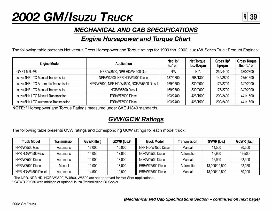
2002 GM/Isuzu
2002 GM/ISUZU TRUCK 39PA
GE
MECHANICAL AND CAB SPECIFICATIONSEngine Horsepower and Torque Chart
The following table presents Net versus Gross Horsepower and Torque ratings for 1999 thru 2002 Isuzu/W-Series Truck Product Engines:
Engine Model ApplicationNet Hp1 Net Torque1 Gross Hp1 Gross Torque1
hp/rpm lbs.-ft./rpm hp/rpm lbs.-ft./rpmGMPT 5.7L-V8 NPR/W3500, NPR HD/W4500 Gas N/A N/A 250/4400 330/2800
Isuzu 4HE1-TC Manual Transmission NPR/W3500, NPR HD/W4500 Diesel 137/2800 268/1300 142/2800 275/1300
Isuzu 4HE1-TC Automatic Transmission NPR/W3500, NPR HD/W4500, NQR/W5500 Diesel 169/2700 339/2000 175/2700 347/2000
Isuzu 4HE1-TC Manual Transmission NQR/W5500 Diesel 169/2700 339/2000 175/2700 347/2000
Isuzu 6HK1-TC Manual Transmission FRR/WT5500 Diesel 193/2400 426/1500 200/2400 441/1500
Isuzu 6HK1-TC Automatic Transmission FRR/WT5500 Diesel 193/2400 426/1500 200/2400 441/1500
NOTE: 1 Horsepower and Torque Ratings measured under SAE J1349 standards.
GVW/GCW Ratings
The following table presents GVW ratings and corresponding GCW ratings for each model truck:
Truck Model Transmission GVWR (lbs.) GCWR (lbs.)1 Truck Model Transmission GVWR (lbs.) GCWR (lbs.)1
NPR/W3500 Gas Automatic 12,000 15,000 NPR HD/W4500 Diesel Manual 14,500 20,500
NPR HD/W4500 Gas Automatic 14,050 17,050 NQR/W5500 Diesel Automatic 17,950 19,5002
NPR/W3500 Diesel Automatic 12,000 18,000 NQR/W5500 Diesel Manual 17,950 22,500
NPR/W3500 Diesel Manual 12,000 18,000 FRR/WT5500 Diesel Automatic 18,000/19,500 22,050
NPR HD/W4500 Diesel Automatic 14,500 19,500 FRR/WT5500 Diesel Manual 18,000/19,500 30,0001 The NPR, NPR HD, NQR/W3500, W4500, W5500 are not approved for Hot Shot applications.2 GCWR 20,950 with addition of optional Isuzu Transmission Oil Cooler.
(Mechanical and Cab Specifications Section – continued on next page)
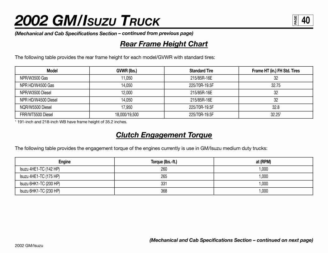
2002 GM/Isuzu
2002 GM/ISUZU TRUCK 40PA
GE
(Mechanical and Cab Specifications Section – continued from previous page)
Rear Frame Height Chart
The following table provides the rear frame height for each model/GVWR with standard tires:
Model GVWR (lbs.) Standard Tire Frame HT (in.) FH Std. TiresNPR/W3500 Gas 11,050 215/85R-16E 32
NPR HD/W4500 Gas 14,050 225/70R-19.5F 32.75
NPR/W3500 Diesel 12,000 215/85R-16E 32
NPR HD/W4500 Diesel 14,050 215/85R-16E 32
NQR/W5500 Diesel 17,950 225/70R-19.5F 32.8
FRR/WT5500 Diesel 18,000/19,500 225/70R-19.5F 32.251
1 191-inch and 218-inch WB have frame height of 35.2 inches.
Clutch Engagement Torque
The following table provides the engagement torque of the engines currently is use in GM/Isuzu medium duty trucks:
Engine Torque (lbs.-ft.) at (RPM)Isuzu 4HE1-TC (142 HP) 260 1,000
Isuzu 4HE1-TC (175 HP) 265 1,000
Isuzu 6HK1-TC (200 HP) 331 1,000
Isuzu 6HK1-TC (230 HP) 368 1,000
(Mechanical and Cab Specifications Section – continued on next page)
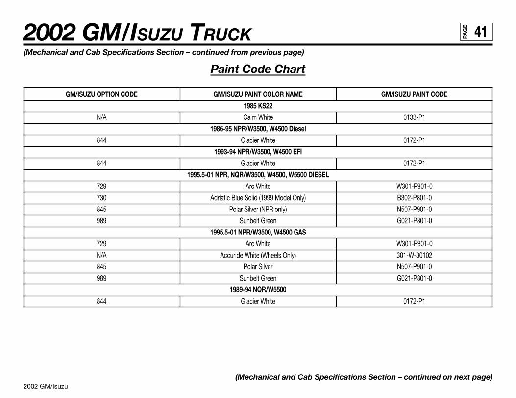
2002 GM/Isuzu
2002 GM/ISUZU TRUCK 41PA
GE
(Mechanical and Cab Specifications Section – continued from previous page)
Paint Code Chart
GM/ISUZU OPTION CODE GM/ISUZU PAINT COLOR NAME GM/ISUZU PAINT CODE1985 KS22
N/A Calm White 0133-P1
1986-95 NPR/W3500, W4500 Diesel844 Glacier White 0172-P1
1993-94 NPR/W3500, W4500 EFI844 Glacier White 0172-P1
1995.5-01 NPR, NQR/W3500, W4500, W5500 DIESEL729 Arc White W301-P801-0
730 Adriatic Blue Solid (1999 Model Only) B302-P801-0
845 Polar Silver (NPR only) N507-P901-0
989 Sunbelt Green G021-P801-0
1995.5-01 NPR/W3500, W4500 GAS729 Arc White W301-P801-0
N/A Accuride White (Wheels Only) 301-W-30102
845 Polar Silver N507-P901-0
989 Sunbelt Green G021-P801-0
1989-94 NQR/W5500844 Glacier White 0172-P1
(Mechanical and Cab Specifications Section – continued on next page)
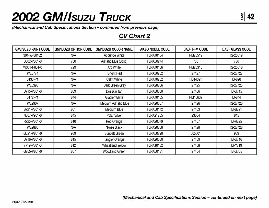
2002 GM/Isuzu
2002 GM/ISUZU TRUCK 42PA
GE
(Mechanical and Cab Specifications Section – continued from previous page)
CV Chart 2
GM/ISUZU PAINT CODE GM/ISUZU OPTION CODE GM/ISUZU COLOR NAME AKZO NOBEL CODE BASF R-M CODE BASF GLASS CODE301-W-30102 N/A Accuride White FLNA40154 RM23519 IS-25319
B302-P801-0 730 Adriatic Blue (Solid) FLNA50274 730 730
W301-P801-0 729 Arc White FLNA40156 RM25318 IS-25318
WE8774 N/A *Bright Red FLNA30252 27427 IS-27427
0133-P1 N/A Calm White FLNA40252 HS14391 IS-820
WE5398 N/A *Dark Green Gray FLNA90856 27425 IS-27425
U715-P801-0 809 Doeskin Tan FLNA80050 27406 IS-U715
0172-P1 844 Glacier White FLNA40155 RM15602 IS-844
WE9907 N/A *Medium Adriatic Blue FLNA90857 27426 IS-27426
B721-P801-0 801 Medium Blue FLNA50172 27403 IS-B721
N507-P901-0 845 Polar Silver FLNA91205 23664 845
R725-P801-0 810 Red Orange FLNA20079 27407 IS-R725
WE9885 N/A *Rose Black FLNA90858 27428 IS-27428
G021-P801-0 989 Sunbelt Green FLNA60290 605301 989
U716-P801-0 815 Tangier Orange FLNA20080 27409 IS-U716
Y719-P801-0 812 Wheatland Yellow FLNA10182 27408 IS-Y719
G705-P801-0 807 Woodland Green FLNA60181 27404 IS-G705
(Mechanical and Cab Specifications Section – continued on next page)
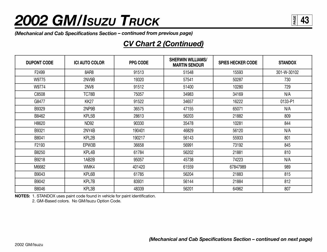
2002 GM/Isuzu
2002 GM/ISUZU TRUCK 43PA
GE
(Mechanical and Cab Specifications Section – continued from previous page)
CV Chart 2 (Continued)
DUPONT CODE ICI AUTO COLOR PPG CODESHERWIN WILLIAMS/
SPIES HECKER CODE STANDOXMARTIN SENOURF2499 8AR8 91513 51548 15593 301-W-30102
W9775 2NV9B 19320 57541 50287 730
W9774 2NV8 91512 51400 10280 729
C8508 TC78B 75057 34983 34169 N/A
G8477 KK27 91522 34657 16222 0133-P1
B9329 2NP9B 36575 47155 65071 N/A
B8462 KPL5B 28613 56203 21882 809
H8620 ND92 90330 35478 10281 844
B9321 2NY4B 190401 46829 56120 N/A
B8041 KPL2B 190217 56143 55933 801
F2193 EPW3B 36658 56991 73192 845
B8250 KPL4B 61784 56202 21881 810
B9218 1AB2B 95057 45738 74223 N/A
M6682 WMK4 401420 61559 67847989 989
B9043 KPL6B 61785 56204 21883 815
B9042 KPL7B 83931 56144 21884 812
B8046 KPL3B 48339 56201 64962 807NOTES: 1. STANDOX uses paint code found in vehicle for paint identification.
2. GM-Based colors. No GM/Isuzu Option Code.
(Mechanical and Cab Specifications Section – continued on next page)
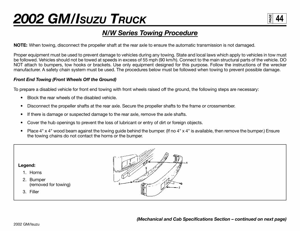
2002 GM/Isuzu
2002 GM/ISUZU TRUCK 44PA
GE
N/W Series Towing Procedure
NOTE: When towing, disconnect the propeller shaft at the rear axle to ensure the automatic transmission is not damaged.
Proper equipment must be used to prevent damage to vehicles during any towing. State and local laws which apply to vehicles in tow mustbe followed. Vehicles should not be towed at speeds in excess of 55 mph (90 km/h). Connect to the main structural parts of the vehicle. DONOT attach to bumpers, tow hooks or brackets. Use only equipment designed for this purpose. Follow the instructions of the wreckermanufacturer. A safety chain system must be used. The procedures below must be followed when towing to prevent possible damage.
Front End Towing (Front Wheels Off the Ground)
To prepare a disabled vehicle for front end towing with front wheels raised off the ground, the following steps are necessary:
• Block the rear wheels of the disabled vehicle.
• Disconnect the propeller shafts at the rear axle. Secure the propeller shafts to the frame or crossmember.
• If there is damage or suspected damage to the rear axle, remove the axle shafts.
• Cover the hub openings to prevent the loss of lubricant or entry of dirt or foreign objects.
• Place 4" x 4" wood beam against the towing guide behind the bumper. (If no 4" x 4" is available, then remove the bumper.) Ensurethe towing chains do not contact the horns or the bumper.
Legend:
1. Horns
2. Bumper(removed for towing)
3. Filler
(Mechanical and Cab Specifications Section – continued on next page)
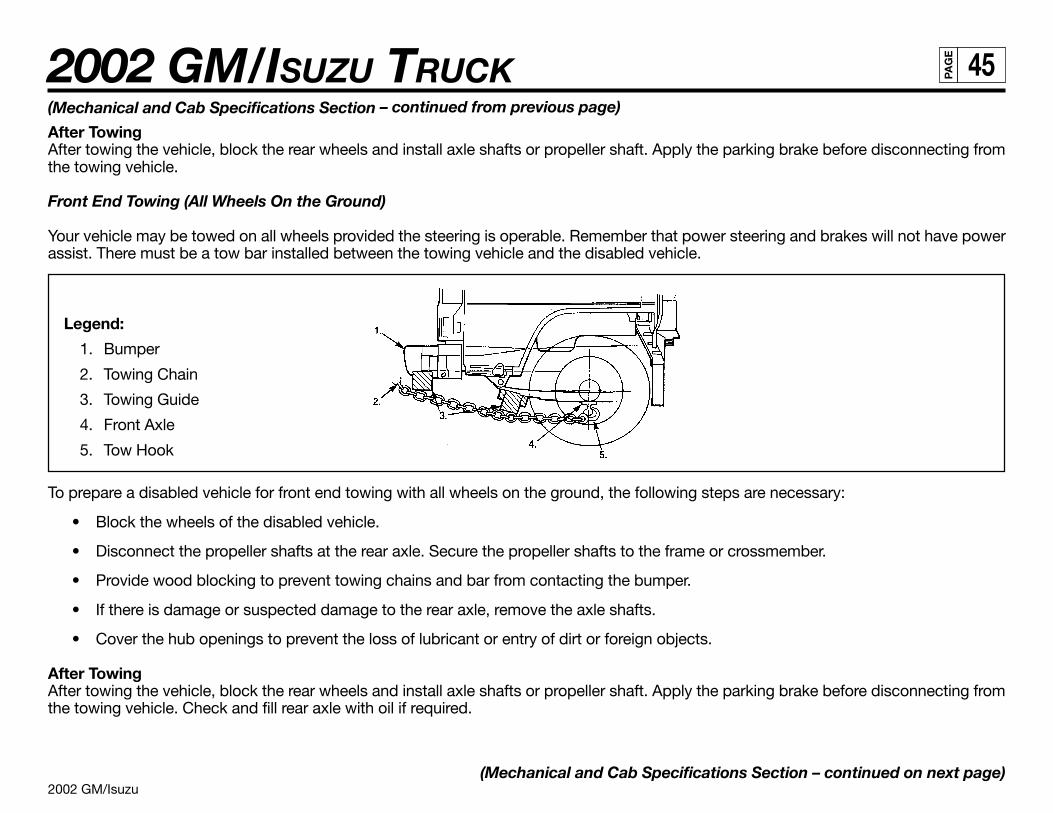
2002 GM/Isuzu
2002 GM/ISUZU TRUCK 45PA
GE
(Mechanical and Cab Specifications Section – continued from previous page)
After TowingAfter towing the vehicle, block the rear wheels and install axle shafts or propeller shaft. Apply the parking brake before disconnecting fromthe towing vehicle.
Front End Towing (All Wheels On the Ground)
Your vehicle may be towed on all wheels provided the steering is operable. Remember that power steering and brakes will not have powerassist. There must be a tow bar installed between the towing vehicle and the disabled vehicle.
Legend:
1. Bumper
2. Towing Chain
3. Towing Guide
4. Front Axle
5. Tow Hook
To prepare a disabled vehicle for front end towing with all wheels on the ground, the following steps are necessary:
• Block the wheels of the disabled vehicle.
• Disconnect the propeller shafts at the rear axle. Secure the propeller shafts to the frame or crossmember.
• Provide wood blocking to prevent towing chains and bar from contacting the bumper.
• If there is damage or suspected damage to the rear axle, remove the axle shafts.
• Cover the hub openings to prevent the loss of lubricant or entry of dirt or foreign objects.
After TowingAfter towing the vehicle, block the rear wheels and install axle shafts or propeller shaft. Apply the parking brake before disconnecting fromthe towing vehicle. Check and fill rear axle with oil if required.
(Mechanical and Cab Specifications Section – continued on next page)
2002 GM/Isuzu
2002 GM/ISUZU TRUCK 46PA
GE
(Mechanical and Cab Specifications Section – continued from previous page)
Rear End Towing (Rear Wheels Off the Ground)
When towing a vehicle with rear wheels raised, secure the steering wheel to maintain straight-ahead position. Make certain that the front axleis not loaded above the front axle Gross Axle Weight Rating (GAWR) as indicated on the vehicle’s VIN and Weight Rating plate.
Special Towing Instructions:
1. All state and local laws regarding such items as warning signals, night illumination, speed, etc., must be followed.
2. Safety chains must be used.
3. No vehicle should ever be towed over 55 mph (90 km/h).
4. Loose or protruding parts of damaged vehicles should be secured prior to moving.
5. A safety chain system completely independent of the primary lifting and towing attachment must be used.
6. Operators should refrain from going under a vehicle which is being lifted by the towing equipment unless the vehicle isadequately supported by safety stands.
7. No towing operation which for any reason jeopardizes the safety of the wrecker operator or any bystanders or other motoristsshould be attempted.
(Mechanical and Cab Specifications Section – continued on next page)
2002 GM/Isuzu
2002 GM/ISUZU TRUCK 47PA
GE
(Mechanical and Cab Specifications Section – continued from previous page)
FRR/WT5500 Series Towing Procedure
Your vehicle should be towed by an authorized dealership or professional towing service to prevent damage. Proper equipment must beused and state (Provincial in Canada) and local laws, which apply to vehicles in tow, must be followed. Vehicles should not be towed inexcess of 55 mph (90 km/h).
Connect to the main structural parts of the vehicle. Do not attach to bumpers, tow hooks or brackets. Use only equipment designed for thispurpose. Follow the instructions of the wrecker manufacturer.
A safety chain system must be used.
Front End Towing (Front Wheels Off the Ground)
Before TowingBlock the rear wheels of the disabled vehicle. Release the parking brake as described under “Air-Operated Parking Brake” in this section.Drain rear axle oil and remove the axle shafts. Cover the hub openings to prevent the loss of lubricant or entry of dirt or foreign objects.
After TowingAfter towing the vehicle, block the rear wheels, remove the covers from the hub openings and install the axle shafts. Apply the parking brakebefore disconnecting from the towing vehicle. Check and fill rear axle with oil if required.
Front End Towing (All Wheels On the Ground)
Your vehicle may be towed on all wheels provided the steering is operable. Remember that power steering will not have power assist. If airpressure is exhausted, the vehicle will not have brakes. There must be a tow bar installed between the towing and the disabled vehicle.
Before TowingBlock the wheels of the disabled vehicle. Disconnect the propshaft at the rear axle. Secure the propshaft to the frame or crossmember. Ifthere is damage or suspected damage to the rear axle, drain oil and remove the axle shafts. Cover the hub openings to prevent the loss oflubricant or entry of dirt or foreign objects.
After TowingAfter towing the vehicle, block the rear wheels and install axle and propeller shafts. Check for proper phasing of universal joints. Apply theparking brake before disconnecting from the towing vehicle. Check and fill rear axle with oil if required.
(Mechanical and Cab Specifications Section – continued on next page)
2002 GM/Isuzu
2002 GM/ISUZU TRUCK 48PA
GE
(Mechanical and Cab Specifications Section – continued from previous page)
Rear End Towing (Rear Wheels Off the Ground)
Before TowingSecure the steering wheel to maintain straight-ahead position. Make certain that the front axle is not loaded above the front axle Gross AxleWeight Rating (GAWR) as indicated on the vehicle’s VIN and Weight Rating plate.
After TowingBlock the rear wheels and release the steering. Apply the parking brake before disconnecting from the towing vehicle. Check and fill the rearaxle with oil as required.
Special Towing Instructions:
1. Call your local authorized dealership or professional towing service.
2. All state and local laws regarding such items as warning signals, night illumination, speed, etc. must be followed.
3. Safety chains must be used.
4. No vehicle should ever be towed over 55 mph (90 km/h).
5. Loose or protruding parts of damaged vehicles should be secured before moving.
6. A safety chain system completely independent of the primary lifting and towing attachment must be used.
7. Operators should refrain from going under a vehicle, which is being lifted by the towing equipment unless the vehicle is adequatelysupported by safety stands.
8. No towing operation, which for any reason jeopardizes the safety of the wrecker operator or any bystanders or other motorists,should be attempted.
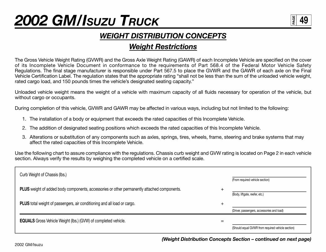
2002 GM/Isuzu
2002 GM/ISUZU TRUCK 49PA
GE
WEIGHT DISTRIBUTION CONCEPTSWeight Restrictions
The Gross Vehicle Weight Rating (GVWR) and the Gross Axle Weight Rating (GAWR) of each Incomplete Vehicle are specified on the coverof its Incomplete Vehicle Document in conformance to the requirements of Part 568.4 of the Federal Motor Vehicle SafetyRegulations. The final stage manufacturer is responsible under Part 567.5 to place the GVWR and the GAWR of each axle on the FinalVehicle Certification Label. The regulation states that the appropriate rating “shall not be less than the sum of the unloaded vehicle weight,rated cargo load, and 150 pounds times the vehicle’s designated seating capacity.”
Unloaded vehicle weight means the weight of a vehicle with maximum capacity of all fluids necessary for operation of the vehicle, butwithout cargo or occupants.
During completion of this vehicle, GVWR and GAWR may be affected in various ways, including but not limited to the following:
1. The installation of a body or equipment that exceeds the rated capacities of this Incomplete Vehicle.
2. The addition of designated seating positions which exceeds the rated capacities of this Incomplete Vehicle.
3. Alterations or substitution of any components such as axles, springs, tires, wheels, frame, steering and brake systems that mayaffect the rated capacities of this Incomplete Vehicle.
Use the following chart to assure compliance with the regulations. Chassis curb weight and GVW rating is located on Page 2 in each vehiclesection. Always verify the results by weighing the completed vehicle on a certified scale.
Curb Weight of Chassis (lbs.)(From required vehicle section)
PLUS weight of added body components, accessories or other permanently attached components. +(Body, liftgate, reefer, etc.)
PLUS total weight of passengers, air conditioning and all load or cargo. +(Driver, passengers, accessories and load)
EQUALS Gross Vehicle Weight (lbs.) (GVW) of completed vehicle. =(Should equal GVWR from required vehicle section)
(Weight Distribution Concepts Section – continued on next page)
2002 GM/Isuzu
2002 GM/ISUZU TRUCK 50PA
GE
(Weight Distribution Concepts Section – continued from previous page)
Gross Axle Weight Rating
The Gross Vehicle Weight is further restricted by the Gross AxIe Weight Rating (GAWR). The maximum GAWR for both front and rear axlesis listed in each Vehicle Section. Weight distribution calculations must be performed to ensure GAWR is not exceeded. Always verify theresults by weighing the completed vehicle on a certified scale.
NOTE: Although the Front Gross Axle Weight Rating (FGAWR) plus the Rear Gross Axle Weight Rating (RGAWR) may exceed the GrossVehicle Weight Rating (GVWR), the total GVW may not exceed the respective maximum GVWR.
The variation in the GAWRs allow the second stage manufacturer some flexibility in the design of the weight distribution of the attached unit.
Weighing the Vehicle
Front and rear GAWRs and total GVWR should be verified by weighing a completed loaded vehicle. Weigh the front and rear of the vehicleseparately and combine the weights for the total GVWR. All three weights must be less than the respective maximum shown in the vehiclesections.
Tire Inflation
Tire inflation must be compatible with GAWR and GVWR as specified on the cover of the Incomplete Vehicle Document for each vehicle.
Center of Gravity
The design of the truck body should be such that the center of gravity of the added load does not exceed the guidelines as listed in eachVehicle Section. If the body is mounted in such a way that the center of gravity height exceeds the maximum height of the center of gravitydesignated for each model, the directional stability at braking and roll stability at cornering will be adversely affected. A vertical and/orhorizontal center of gravity calculation must be performed if a question in stability arises to ensure the designed maximum height of thecenter of gravity is not violated.
(Weight Distribution Concepts Section – continued on next page)
2002 GM/Isuzu
2002 GM/ISUZU TRUCK 51PA
GE
(Weight Distribution Concepts Section – continued from previous page)
Weight Distribution
A truck as a commercial vehicle has but one purpose. That purpose is to haul some commodity from one place to another. A short distanceor a long distance, the weight to be hauled, more than any other factor, determines the size of the truck. A small weight requires only a smalltruck; a large weight requires a large truck. A simple principle, but it can easily be misapplied. In any case, selecting the right size truck forthe load to be hauled will ensure that the job will be done and that it will be able to be done with some degree of reliability and within the legallimitations of total gross weight and axle gross weights.
Not only must a truck be selected that will handle the total load, but the weight must also be properly distributed between the axles. This isof extreme importance from both a functional and economic aspect. If a truck consistently hauls less than its capacity, the owner is notrealizing full return on his investment and his operating costs will be higher than they should be. If the truck is improperly loaded oroverloaded, profits will be reduced due to increased maintenance costs and potential fines resulting from overloading beyond legal limita-tions. Careful consideration must be given to distribution of the load weight in order to determine how much of the total, including chassis,cab, body and payload, will be carried on the front axle and how much will be carried on the rear axle, on the trailer axles and the total.Moving a load a few inches forward or backward on the chassis can mean the difference between acceptable weight distribution for thetruck or an application that will not do the job satisfactorily.
Every truck has a specific capacity and should be loaded so that the load distribution is kept within Gross Axle Weight Ratings (GAWR) andthe truck’s Gross Vehicle Weight Rating (GVWR) or Gross Combination Weight Rating (GCWR) for a tractor/trailer and the weight laws andregulations under which the truck will operate. Improper weight distribution will cause problems in many areas:
1. Excessive front end wear and failure
a. Tie-rod and kingpin wear
b. Front axle failure
c. Overloading of front suspension
d. Wheel bearing failure
2. Rapid tire wear
a. When the weight on a tire exceeds its rating capacity, accelerated wear will result and could result in tire failure.
(Weight Distribution Concepts Section – continued on next page)
2002 GM/Isuzu
2002 GM/ISUZU TRUCK 52PA
GE
(Weight Distribution Concepts Section – continued from previous page)
3. Rough, erratic ride
a. If the center of the payload is directly over or slightly behind the rear axle, the lack of sufficient weight on the front axle willcreate a bobbing effect, very rough ride, and erratic steering. This condition will be magnified when the truck is going uphill.
4. Hard steering
a. When loads beyond the capacity of the front axle are imposed upon it, the steering mechanism is also overloaded and hardsteering will result.
b. Excessive overloading could result in steering component damage or failure.
5. Unsafe operating and conditions
a. Poor traction on the steering axle effects the safety of the driver and equipment, particularly on wet, icy and slippery surfaces.Experience indicates that approximately 30% of the total weight at the ground on a truck or tractor should be on the front axlewith a low cab forward vehicle.
b. When a truck is overloaded, a dangerous situation may exist because minimum speeds cannot always be maintained, direc-tional control may not be precise and insufficient braking capacity can cause longer than normal braking distances.
6. High maintenance costs
a. Improper weight distribution and overloading cause excessive wear and premature failure of parts. Additional stressesimposed on the frame by the misapplication of wheelbases may be instrumental in causing the frame to crack or break.
7. Noncompliance with weight laws and regulations
a. When there is the possibility that axle loads will exceed existing weight laws and regulations, careful weight distribution isnecessary to provide a correct balance between front and rear axle loads and total load within legal limitations.
In this way, maximum payloads may be carried without exceeding legal limits. If the body is too long for a wheelbase, the center of the bodyand payload is placed directly over the rear axle. This places all the payload on the rear axles, resulting in overloading the rear tires, rear axlesprings and wheel bearings and potentially exceeding the rear axle legal weight limit. The front axle is then carrying no part of the payloadand is easily lifted off the ground when going over rough terrain, creating a very rough ride and temporary loss of steering control. If the bodyis too short for the wheelbase used, frame stress may be increased and may result in excessive loads on the front axle. Excessive front axleloads increase wear on the kingpins and bushings, wheel bearings and steering gear. Excessive front axle loads also overstress the frontaxle, springs, tires and wheels. All of these contribute directly to higher maintenance costs and hard steering, both of which are undesirable.
(Weight Distribution Concepts Section – continued on next page)
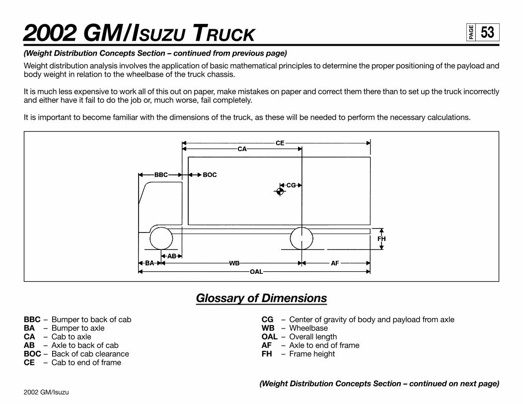
2002 GM/Isuzu
2002 GM/ISUZU TRUCK 53PA
GE
(Weight Distribution Concepts Section – continued from previous page)
Weight distribution analysis involves the application of basic mathematical principles to determine the proper positioning of the payload andbody weight in relation to the wheelbase of the truck chassis.
It is much less expensive to work all of this out on paper, make mistakes on paper and correct them there than to set up the truck incorrectlyand either have it fail to do the job or, much worse, fail completely.
It is important to become familiar with the dimensions of the truck, as these will be needed to perform the necessary calculations.
Glossary of Dimensions
BBC – Bumper to back of cab CG – Center of gravity of body and payload from axleBA – Bumper to axle WB – WheelbaseCA – Cab to axle OAL – Overall lengthAB – Axle to back of cab AF – Axle to end of frameBOC – Back of cab clearance FH – Frame heightCE – Cab to end of frame
(Weight Distribution Concepts Section – continued on next page)
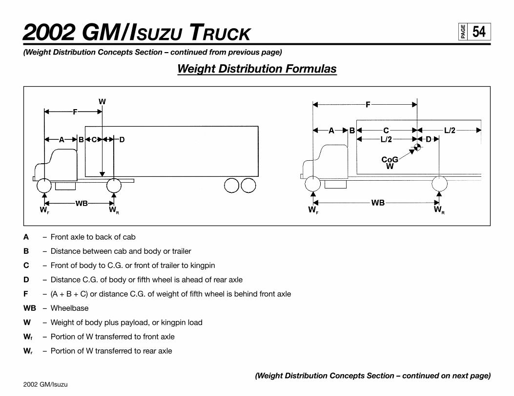
2002 GM/Isuzu
2002 GM/ISUZU TRUCK 54PA
GE
(Weight Distribution Concepts Section – continued from previous page)
Weight Distribution Formulas
A – Front axle to back of cab
B – Distance between cab and body or trailer
C – Front of body to C.G. or front of trailer to kingpin
D – Distance C.G. of body or fifth wheel is ahead of rear axle
F – (A + B + C) or distance C.G. of weight of fifth wheel is behind front axle
WB – Wheelbase
W – Weight of body plus payload, or kingpin load
Wf – Portion of W transferred to front axle
Wr – Portion of W transferred to rear axle
(Weight Distribution Concepts Section – continued on next page)

2002 GM/Isuzu
2002 GM/ISUZU TRUCK 55PA
GE
(Weight Distribution Concepts Section – continued from previous page)
Basic Formulas
(a) W x D = Wf x WB (c) WB = (A + B + C + D) = (F + D)or
(b) W x F = Wr x WB (d) W = Wf x Wr
Weight Distribution Formulas in Words
To find:
1. Weight transferred to front axle = (Total weight) x (Distance C.G. is ahead of the rear axle)(Wheelbase)
2. Distance C.G. must be placed ahead of rear axle = (Weight transferred to the front axle) x (Wheelbase)(Total weight)
3. Wheelbase = (Total weight) x (Distance C.G. is ahead of the rear axle)(Weight to be transferred to the front axle)
4. Total Weight = (Weight to be transferred to the front axle) x (Wheelbase)(Distance C.G. is ahead of the rear axle)
(Weight Distribution Concepts Section – continued on next page)
1. Wf = W x DWB
2. D = Wf x WBW
3. WB = W x DWf
4. W = Wf x WBD
5. Wr = W x FWB
6. F = Wr x WBW
7. WB = W x FWr
8. W = Wr x WBF
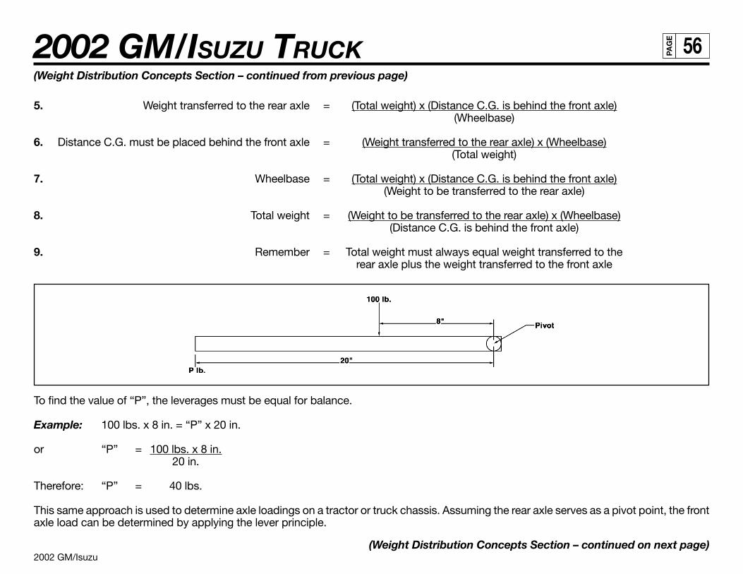
2002 GM/Isuzu
2002 GM/ISUZU TRUCK 56PA
GE
(Weight Distribution Concepts Section – continued from previous page)
5. Weight transferred to the rear axle = (Total weight) x (Distance C.G. is behind the front axle)(Wheelbase)
6. Distance C.G. must be placed behind the front axle = (Weight transferred to the rear axle) x (Wheelbase)(Total weight)
7. Wheelbase = (Total weight) x (Distance C.G. is behind the front axle)(Weight to be transferred to the rear axle)
8. Total weight = (Weight to be transferred to the rear axle) x (Wheelbase)(Distance C.G. is behind the front axle)
9. Remember = Total weight must always equal weight transferred to therear axle plus the weight transferred to the front axle
To find the value of “P”, the leverages must be equal for balance.
Example: 100 lbs. x 8 in. = “P” x 20 in.
or “P” = 100 lbs. x 8 in.20 in.
Therefore: “P” = 40 lbs.
This same approach is used to determine axle loadings on a tractor or truck chassis. Assuming the rear axle serves as a pivot point, the frontaxle load can be determined by applying the lever principle.
(Weight Distribution Concepts Section – continued on next page)
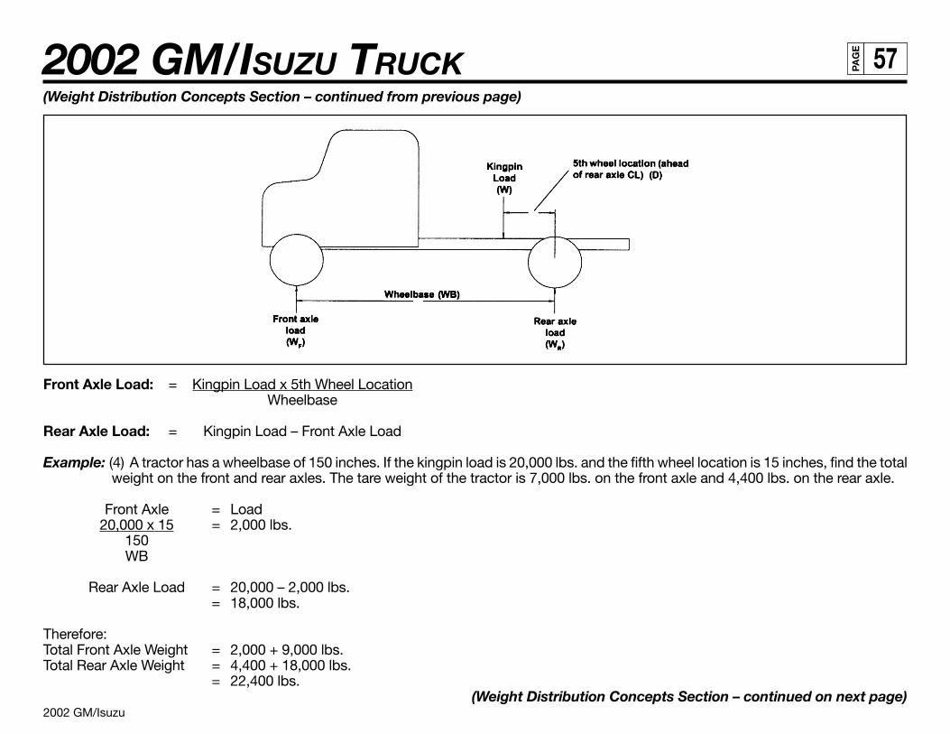
2002 GM/Isuzu
2002 GM/ISUZU TRUCK 57PA
GE
(Weight Distribution Concepts Section – continued from previous page)
Front Axle Load: = Kingpin Load x 5th Wheel LocationWheelbase
Rear Axle Load: = Kingpin Load – Front Axle Load
Example: (4) A tractor has a wheelbase of 150 inches. If the kingpin load is 20,000 lbs. and the fifth wheel location is 15 inches, find the totalweight on the front and rear axles. The tare weight of the tractor is 7,000 lbs. on the front axle and 4,400 lbs. on the rear axle.
Front Axle = Load20,000 x 15 = 2,000 lbs.
150WB
Rear Axle Load = 20,000 – 2,000 lbs.= 18,000 lbs.
Therefore:Total Front Axle Weight = 2,000 + 9,000 lbs.Total Rear Axle Weight = 4,400 + 18,000 lbs.
= 22,400 lbs.(Weight Distribution Concepts Section – continued on next page)
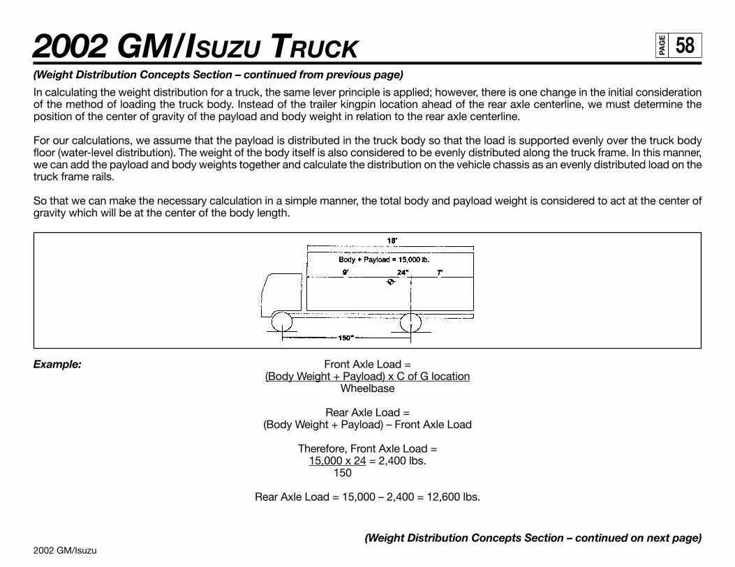
2002 GM/Isuzu
2002 GM/ISUZU TRUCK 58PA
GE
(Weight Distribution Concepts Section – continued from previous page)
In calculating the weight distribution for a truck, the same lever principle is applied; however, there is one change in the initial considerationof the method of loading the truck body. Instead of the trailer kingpin location ahead of the rear axle centerline, we must determine theposition of the center of gravity of the payload and body weight in relation to the rear axle centerline.
For our calculations, we assume that the payload is distributed in the truck body so that the load is supported evenly over the truck bodyfloor (water-level distribution). The weight of the body itself is also considered to be evenly distributed along the truck frame. In this manner,we can add the payload and body weights together and calculate the distribution on the vehicle chassis as an evenly distributed load on thetruck frame rails.
So that we can make the necessary calculation in a simple manner, the total body and payload weight is considered to act at the center ofgravity which will be at the center of the body length.
Example: Front Axle Load =(Body Weight + Payload) x C of G location
Wheelbase
Rear Axle Load =(Body Weight + Payload) – Front Axle Load
Therefore, Front Axle Load =15,000 x 24 = 2,400 lbs.
150
Rear Axle Load = 15,000 – 2,400 = 12,600 lbs.
(Weight Distribution Concepts Section – continued on next page)
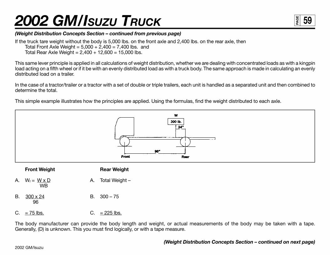
2002 GM/Isuzu
2002 GM/ISUZU TRUCK 59PA
GE
(Weight Distribution Concepts Section – continued from previous page)
If the truck tare weight without the body is 5,000 lbs. on the front axle and 2,400 lbs. on the rear axle, thenTotal Front Axle Weight = 5,000 + 2,400 = 7,400 lbs. andTotal Rear Axle Weight = 2,400 + 12,600 = 15,000 lbs.
This same lever principle is applied in all calculations of weight distribution, whether we are dealing with concentrated loads as with a kingpinload acting on a fifth wheel or if it be with an evenly distributed load as with a truck body. The same approach is made in calculating an evenlydistributed load on a trailer.
In the case of a tractor/trailer or a tractor with a set of double or triple trailers, each unit is handled as a separated unit and then combined todetermine the total.
This simple example illustrates how the principles are applied. Using the formulas, find the weight distributed to each axle.
Front Weight Rear Weight
A. Wf = W x D A. Total Weight –WB
B. 300 x 24 B. 300 – 75 96
C. = 75 lbs. C. = 225 lbs.
The body manufacturer can provide the body length and weight, or actual measurements of the body may be taken with a tape.Generally, (D) is unknown. This you must find logically, or with a tape measure.
(Weight Distribution Concepts Section – continued on next page)
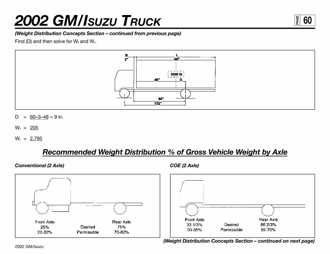
2002 GM/Isuzu
2002 GM/ISUZU TRUCK 60PA
GE
(Weight Distribution Concepts Section – continued from previous page)
Find (D) and then solve for Wf and Wr.
D = 60–3–48 = 9 in.
Wf = 205
Wr = 2,795
Recommended Weight Distribution % of Gross Vehicle Weight by Axle
Conventional (2 Axle) COE (2 Axle)
(Weight Distribution Concepts Section – continued on next page)
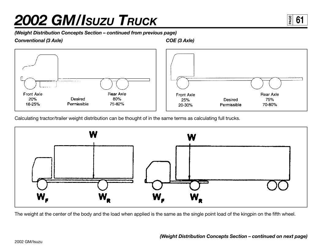
2002 GM/Isuzu
2002 GM/ISUZU TRUCK 61PA
GE
(Weight Distribution Concepts Section – continued from previous page)
Conventional (3 Axle) COE (3 Axle)
Calculating tractor/trailer weight distribution can be thought of in the same terms as calculating full trucks.
The weight at the center of the body and the load when applied is the same as the single point load of the kingpin on the fifth wheel.
(Weight Distribution Concepts Section – continued on next page)
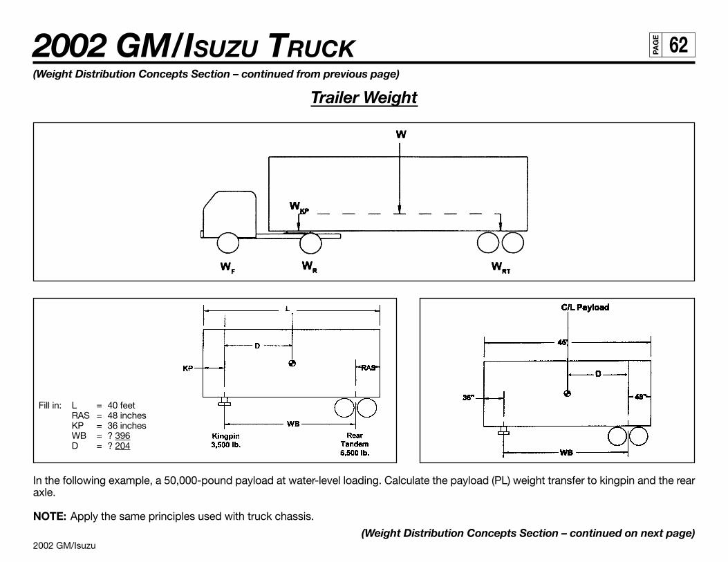
2002 GM/Isuzu
2002 GM/ISUZU TRUCK 62PA
GE
(Weight Distribution Concepts Section – continued from previous page)
Trailer Weight
Fill in: L = 40 feetRAS = 48 inchesKP = 36 inchesWB = ? 396D = ? 204
In the following example, a 50,000-pound payload at water-level loading. Calculate the payload (PL) weight transfer to kingpin and the rearaxle.
NOTE: Apply the same principles used with truck chassis.
(Weight Distribution Concepts Section – continued on next page)
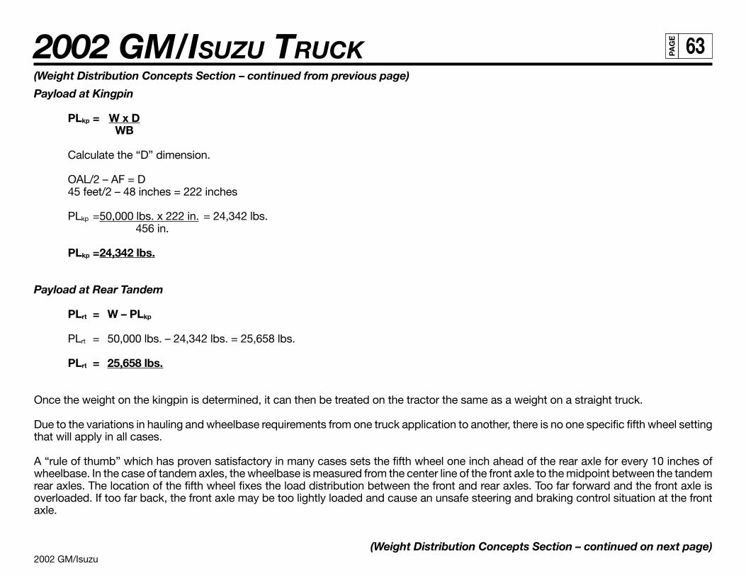
2002 GM/Isuzu
2002 GM/ISUZU TRUCK 63PA
GE
(Weight Distribution Concepts Section – continued from previous page)
Payload at Kingpin
PLkp = W x DWB
Calculate the “D” dimension.
OAL/2 – AF = D45 feet/2 – 48 inches = 222 inches
PLkp =50,000 lbs. x 222 in. = 24,342 lbs.456 in.
PLkp =24,342 lbs.
Payload at Rear Tandem
PLrt = W – PLkp
PLrt = 50,000 lbs. – 24,342 lbs. = 25,658 lbs.
PLrt = 25,658 lbs.
Once the weight on the kingpin is determined, it can then be treated on the tractor the same as a weight on a straight truck.
Due to the variations in hauling and wheelbase requirements from one truck application to another, there is no one specific fifth wheel settingthat will apply in all cases.
A “rule of thumb” which has proven satisfactory in many cases sets the fifth wheel one inch ahead of the rear axle for every 10 inches ofwheelbase. In the case of tandem axles, the wheelbase is measured from the center line of the front axle to the midpoint between the tandemrear axles. The location of the fifth wheel fixes the load distribution between the front and rear axles. Too far forward and the front axle isoverloaded. If too far back, the front axle may be too lightly loaded and cause an unsafe steering and braking control situation at the frontaxle.
(Weight Distribution Concepts Section – continued on next page)
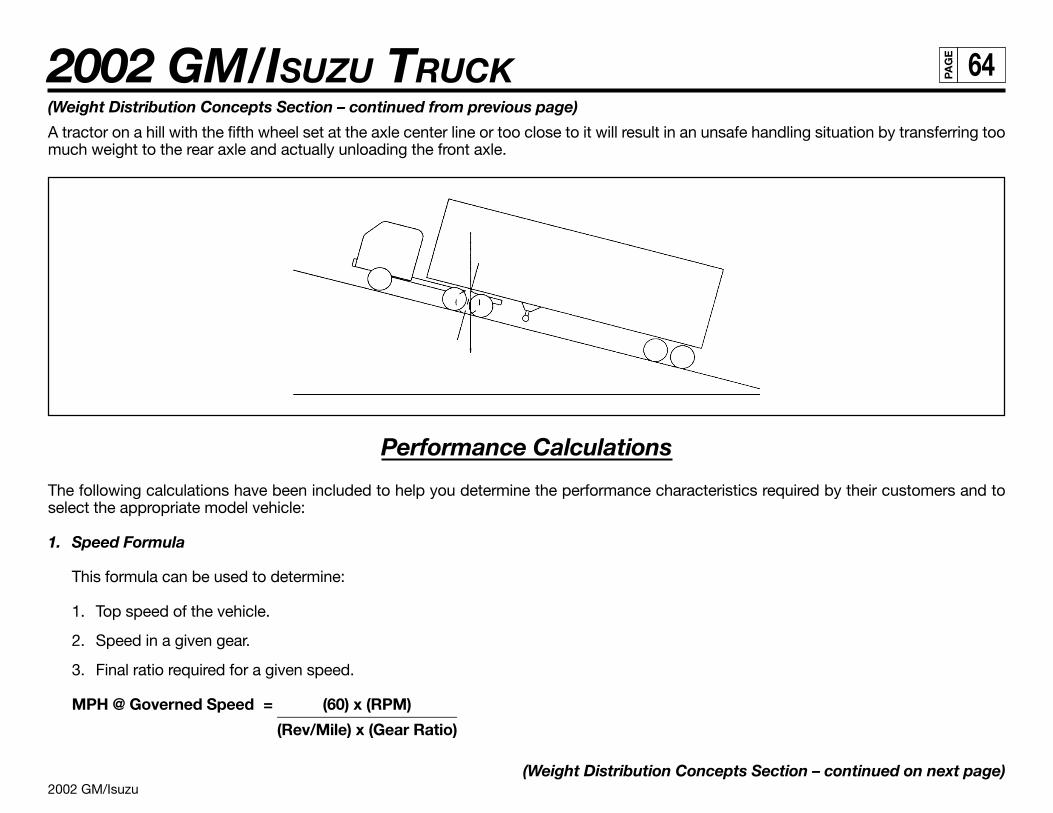
2002 GM/Isuzu
2002 GM/ISUZU TRUCK 64PA
GE
(Weight Distribution Concepts Section – continued from previous page)
A tractor on a hill with the fifth wheel set at the axle center line or too close to it will result in an unsafe handling situation by transferring toomuch weight to the rear axle and actually unloading the front axle.
Performance Calculations
The following calculations have been included to help you determine the performance characteristics required by their customers and toselect the appropriate model vehicle:
1. Speed Formula
This formula can be used to determine:
1. Top speed of the vehicle.
2. Speed in a given gear.
3. Final ratio required for a given speed.
MPH @ Governed Speed = (60) x (RPM)_______________________(Rev/Mile) x (Gear Ratio)
(Weight Distribution Concepts Section – continued on next page)
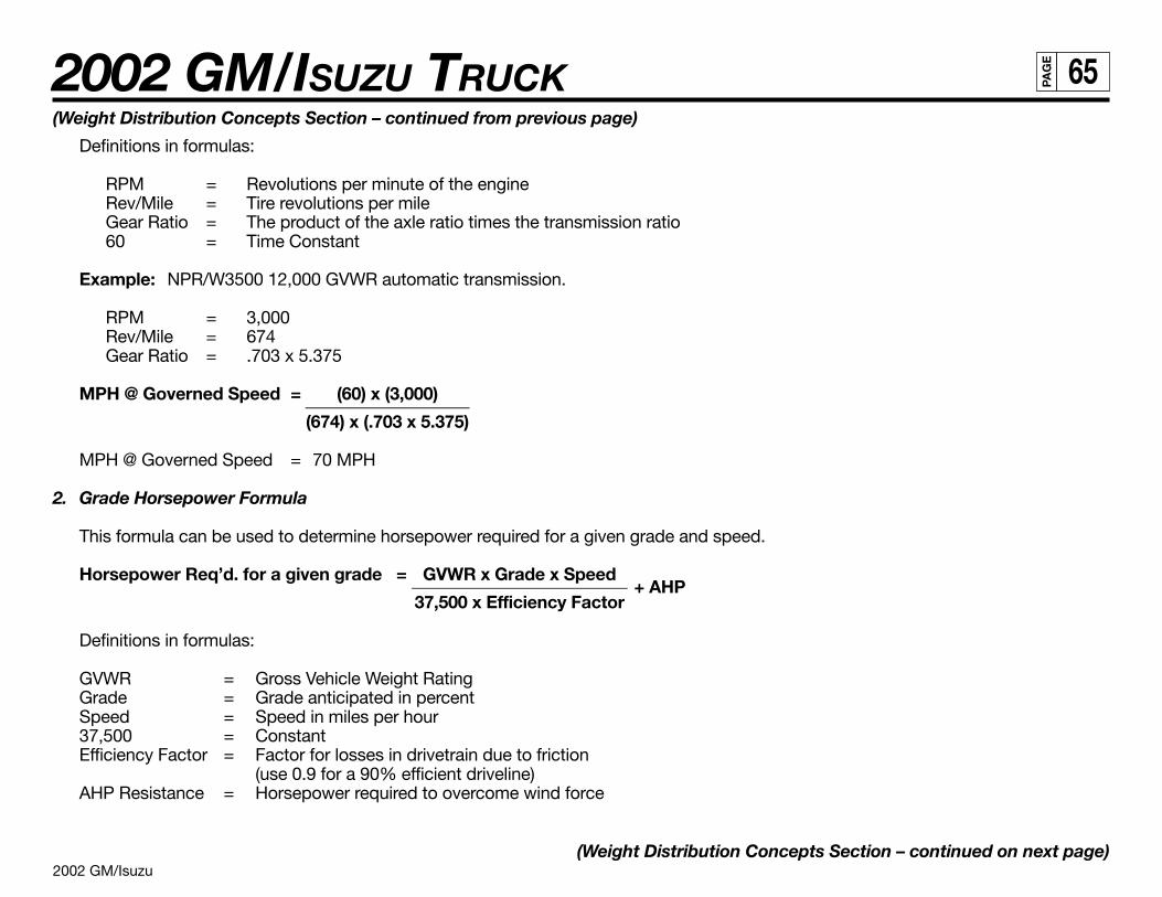
2002 GM/Isuzu
2002 GM/ISUZU TRUCK 65PA
GE
(Weight Distribution Concepts Section – continued from previous page)
Definitions in formulas:
RPM = Revolutions per minute of the engineRev/Mile = Tire revolutions per mileGear Ratio = The product of the axle ratio times the transmission ratio60 = Time Constant
Example: NPR/W3500 12,000 GVWR automatic transmission.
RPM = 3,000Rev/Mile = 674Gear Ratio = .703 x 5.375
MPH @ Governed Speed = (60) x (3,000)___________________(674) x (.703 x 5.375)
MPH @ Governed Speed = 70 MPH
2. Grade Horsepower Formula
This formula can be used to determine horsepower required for a given grade and speed.
Horsepower Req’d. for a given grade = GVWR x Grade x Speed+ AHP_________________________
37,500 x Efficiency Factor
Definitions in formulas:
GVWR = Gross Vehicle Weight RatingGrade = Grade anticipated in percentSpeed = Speed in miles per hour37,500 = ConstantEfficiency Factor = Factor for losses in drivetrain due to friction
(use 0.9 for a 90% efficient driveline)AHP Resistance = Horsepower required to overcome wind force
(Weight Distribution Concepts Section – continued on next page)
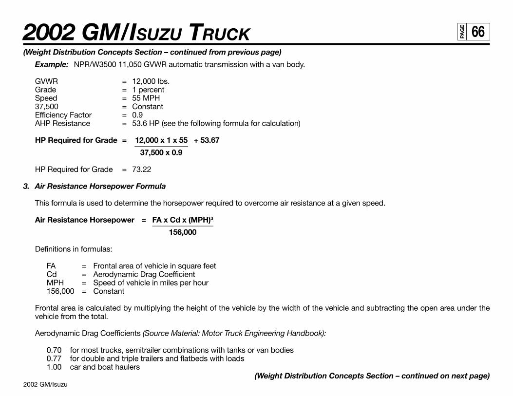
2002 GM/Isuzu
2002 GM/ISUZU TRUCK 66PA
GE
(Weight Distribution Concepts Section – continued from previous page)
Example: NPR/W3500 11,050 GVWR automatic transmission with a van body.
GVWR = 12,000 lbs.Grade = 1 percentSpeed = 55 MPH37,500 = ConstantEfficiency Factor = 0.9AHP Resistance = 53.6 HP (see the following formula for calculation)
HP Required for Grade = 12,000 x 1 x 55 + 53.67______________37,500 x 0.9
HP Required for Grade = 73.22
3. Air Resistance Horsepower Formula
This formula is used to determine the horsepower required to overcome air resistance at a given speed.
Air Resistance Horsepower = FA x Cd x (MPH)3________________
156,000
Definitions in formulas:
FA = Frontal area of vehicle in square feetCd = Aerodynamic Drag CoefficientMPH = Speed of vehicle in miles per hour156,000 = Constant
Frontal area is calculated by multiplying the height of the vehicle by the width of the vehicle and subtracting the open area under thevehicle from the total.
Aerodynamic Drag Coefficients (Source Material: Motor Truck Engineering Handbook):
0.70 for most trucks, semitrailer combinations with tanks or van bodies0.77 for double and triple trailers and flatbeds with loads1.00 car and boat haulers
(Weight Distribution Concepts Section – continued on next page)
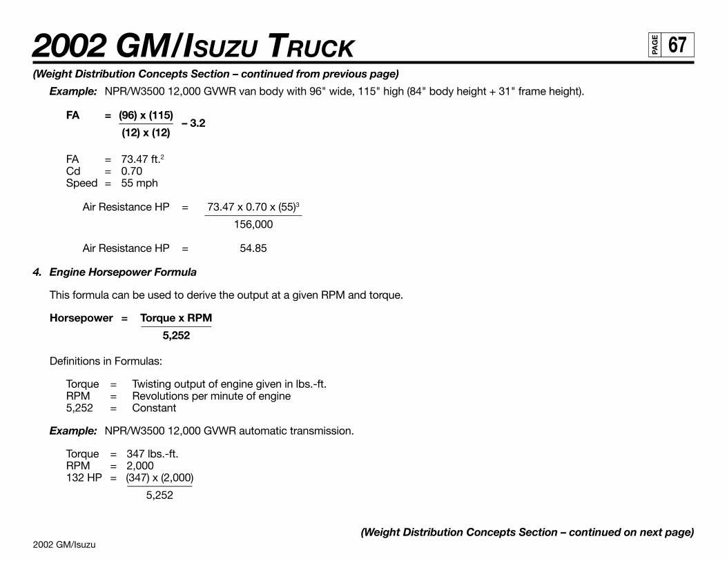
2002 GM/Isuzu
2002 GM/ISUZU TRUCK 67PA
GE
(Weight Distribution Concepts Section – continued from previous page)
Example: NPR/W3500 12,000 GVWR van body with 96" wide, 115" high (84" body height + 31" frame height).
FA = (96) x (115)– 3.2__________
(12) x (12)
FA = 73.47 ft.2Cd = 0.70Speed = 55 mph
Air Resistance HP = 73.47 x 0.70 x (55)3__________________156,000
Air Resistance HP = 54.85
4. Engine Horsepower Formula
This formula can be used to derive the output at a given RPM and torque.
Horsepower = Torque x RPM_____________5,252
Definitions in Formulas:
Torque = Twisting output of engine given in lbs.-ft.RPM = Revolutions per minute of engine5,252 = Constant
Example: NPR/W3500 12,000 GVWR automatic transmission.
Torque = 347 lbs.-ft.RPM = 2,000132 HP = (347) x (2,000)____________
5,252
(Weight Distribution Concepts Section – continued on next page)
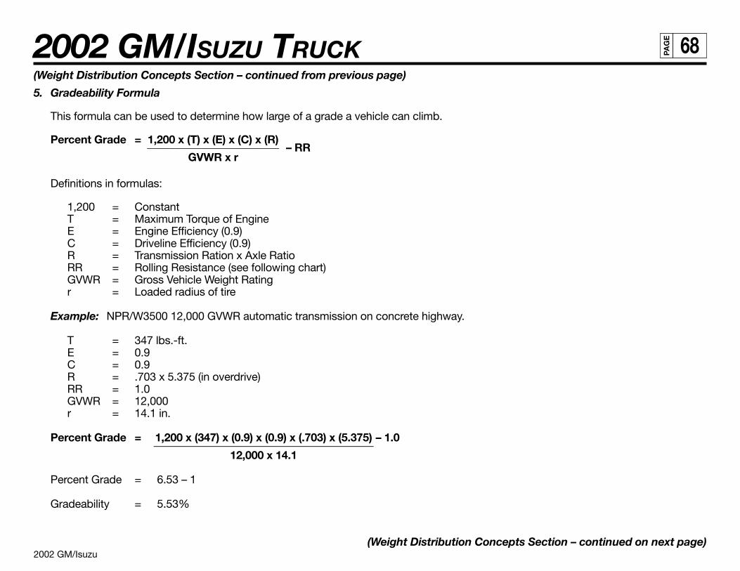
2002 GM/Isuzu
2002 GM/ISUZU TRUCK 68PA
GE
(Weight Distribution Concepts Section – continued from previous page)
5. Gradeability Formula
This formula can be used to determine how large of a grade a vehicle can climb.
Percent Grade = 1,200 x (T) x (E) x (C) x (R)– RR________________________
GVWR x r
Definitions in formulas:
1,200 = ConstantT = Maximum Torque of EngineE = Engine Efficiency (0.9)C = Driveline Efficiency (0.9)R = Transmission Ration x Axle RatioRR = Rolling Resistance (see following chart)GVWR = Gross Vehicle Weight Ratingr = Loaded radius of tire
Example: NPR/W3500 12,000 GVWR automatic transmission on concrete highway.
T = 347 lbs.-ft.E = 0.9C = 0.9R = .703 x 5.375 (in overdrive)RR = 1.0GVWR = 12,000r = 14.1 in.
Percent Grade = 1,200 x (347) x (0.9) x (0.9) x (.703) x (5.375) – 1.0________________________________________12,000 x 14.1
Percent Grade = 6.53 – 1
Gradeability = 5.53%
(Weight Distribution Concepts Section – continued on next page)
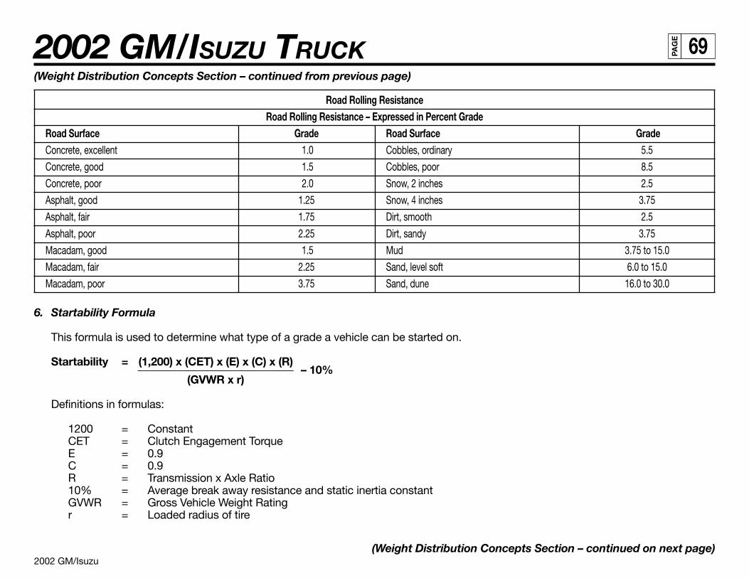
2002 GM/Isuzu
2002 GM/ISUZU TRUCK 69PA
GE
(Weight Distribution Concepts Section – continued from previous page)
Road Rolling ResistanceRoad Rolling Resistance – Expressed in Percent Grade
Road Surface Grade Road Surface GradeConcrete, excellent 1.0 Cobbles, ordinary 5.5
Concrete, good 1.5 Cobbles, poor 8.5
Concrete, poor 2.0 Snow, 2 inches 2.5
Asphalt, good 1.25 Snow, 4 inches 3.75
Asphalt, fair 1.75 Dirt, smooth 2.5
Asphalt, poor 2.25 Dirt, sandy 3.75
Macadam, good 1.5 Mud 3.75 to 15.0
Macadam, fair 2.25 Sand, level soft 6.0 to 15.0
Macadam, poor 3.75 Sand, dune 16.0 to 30.0
6. Startability Formula
This formula is used to determine what type of a grade a vehicle can be started on.
Startability = (1,200) x (CET) x (E) x (C) x (R)– 10%____________________________
(GVWR x r)
Definitions in formulas:
1200 = ConstantCET = Clutch Engagement TorqueE = 0.9C = 0.9R = Transmission x Axle Ratio10% = Average break away resistance and static inertia constantGVWR = Gross Vehicle Weight Ratingr = Loaded radius of tire
(Weight Distribution Concepts Section – continued on next page)
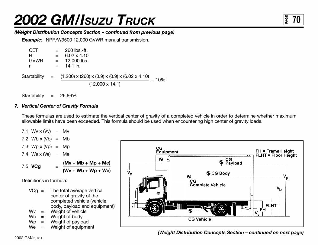
2002 GM/Isuzu
2002 GM/ISUZU TRUCK 70PA
GE
(Weight Distribution Concepts Section – continued from previous page)
Example: NPR/W3500 12,000 GVWR manual transmission.
CET = 260 lbs.-ft.R = 6.02 x 4.10GVWR = 12,000 lbs.r = 14.1 in.
Startability = (1,200) x (260) x (0.9) x (0.9) x (6.02 x 4.10)– 10%_____________________________________
(12,000 x 14.1)
Startability = 26.86%
7. Vertical Center of Gravity Formula
These formulas are used to estimate the vertical center of gravity of a completed vehicle in order to determine whether maximumallowable limits have been exceeded. This formula should be used when encountering high center of gravity loads.
7.1 Wv x (Vv) = Mv
7.2 Wb x (Vb) = Mb
7.3 Wp x (Vp) = Mp
7.4 We x (Ve) = Me
7.5 VCg =(Mv + Mb + Mp + Me)____________________(Wv + Wb + Wp + We)
Definitions in formula:
VCg = The total average verticalcenter of gravity of thecompleted vehicle (vehicle,body, payload and equipment)
Wv = Weight of vehicleWb = Weight of bodyWp = Weight of payloadWe = Weight of equipment
(Weight Distribution Concepts Section – continued on next page)
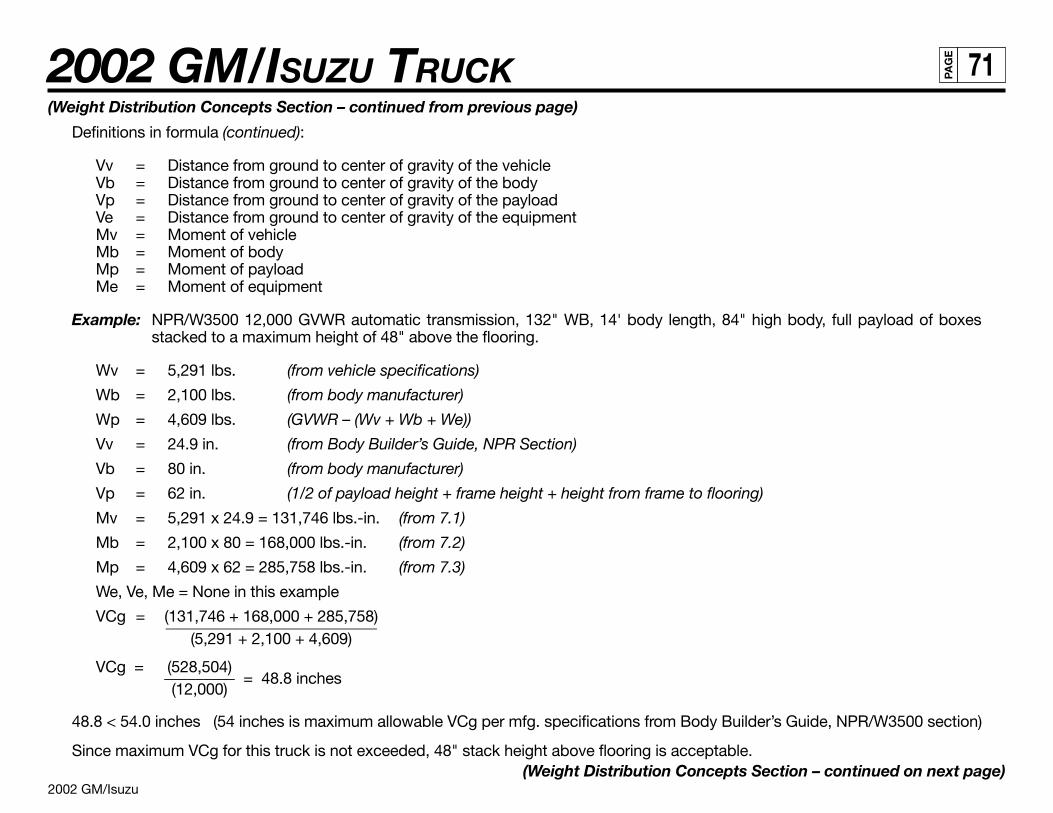
2002 GM/Isuzu
2002 GM/ISUZU TRUCK 71PA
GE
(Weight Distribution Concepts Section – continued from previous page)
Definitions in formula (continued):
Vv = Distance from ground to center of gravity of the vehicleVb = Distance from ground to center of gravity of the bodyVp = Distance from ground to center of gravity of the payloadVe = Distance from ground to center of gravity of the equipmentMv = Moment of vehicleMb = Moment of bodyMp = Moment of payloadMe = Moment of equipment
Example: NPR/W3500 12,000 GVWR automatic transmission, 132" WB, 14' body length, 84" high body, full payload of boxesstacked to a maximum height of 48" above the flooring.
Wv = 5,291 lbs. (from vehicle specifications)
Wb = 2,100 lbs. (from body manufacturer)
Wp = 4,609 lbs. (GVWR – (Wv + Wb + We))
Vv = 24.9 in. (from Body Builder’s Guide, NPR Section)
Vb = 80 in. (from body manufacturer)
Vp = 62 in. (1/2 of payload height + frame height + height from frame to flooring)
Mv = 5,291 x 24.9 = 131,746 lbs.-in. (from 7.1)
Mb = 2,100 x 80 = 168,000 lbs.-in. (from 7.2)
Mp = 4,609 x 62 = 285,758 lbs.-in. (from 7.3)
We, Ve, Me = None in this example
VCg = (131,746 + 168,000 + 285,758)___________________________(5,291 + 2,100 + 4,609)
VCg = (528,504)= 48.8 inches_________
(12,000)
48.8 < 54.0 inches (54 inches is maximum allowable VCg per mfg. specifications from Body Builder’s Guide, NPR/W3500 section)
Since maximum VCg for this truck is not exceeded, 48" stack height above flooring is acceptable.(Weight Distribution Concepts Section – continued on next page)
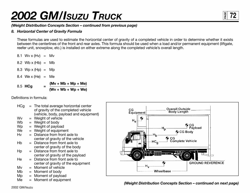
2002 GM/Isuzu
2002 GM/ISUZU TRUCK 72PA
GE
(Weight Distribution Concepts Section – continued from previous page)
8. Horizontal Center of Gravity Formula
These formulas are used to estimate the horizontal center of gravity of a completed vehicle in order to determine whether it existsbetween the centerlines of the front and rear axles. This formula should be used when a load and/or permanent equipment (liftgate,reefer unit, snowplow, etc.) is installed on either extreme along the completed vehicle’s overall length.
8.1 Wv x (Hv) = Mv
8.2 Wb x (Hb) = Mb
8.3 Wp x (Hp) = Mp
8.4 We x (He) = Me
8.5 HCg =(Mv + Mb + Mp + Me)____________________(Wv + Wb + Wp + We)
Definitions in formula:
HCg = The total average horizontal centerof gravity of the completed vehicle(vehicle, body, payload and equipment)
Wv = Weight of vehicleWb = Weight of bodyWp = Weight of payloadWe = Weight of equipmentHv = Distance from front axle to
center of gravity of the vehicleHb = Distance from front axle to
center of gravity of the bodyHp = Distance from front axle to
center of gravity of the payloadHe = Distance from front axle to
center of gravity of the equipmentMv = Moment of vehicleMb = Moment of bodyMp = Moment of payloadMe = Moment of equipment
(Weight Distribution Concepts Section – continued on next page)
2002 GM/Isuzu
2002 GM/ISUZU TRUCK 73PA
GE
(Weight Distribution Concepts Section – continued from previous page)
Example: NPR/W3500 Diesel 12,000 GVWR automatic transmission, 132” WB, 14’ body length, full payload of boxes stacked anddistributed evenly throughout the flooring, 1,000 lb. reefer unit attached in front of body.
Wv = 5,291 lbs. (from vehicle specifications)
Wb = 2,100 lbs. (from body manufacturer)
Wp = 3,609 lbs. (GVWR – (Wv + Wb + We))
We = 1,000 lbs. (from equipment manufacturer)
Hv = 42.4 in. (from Body Builder’s Guide, NPR Section)
Hb = 107.5 in. (from body manufacturer)
Hp* = 107.5 in. (1/2 of payload height + distance from front axle to front of body)
He = 17.5 in. (from equipment manufacturer)
Mv = 5,291 x 42.4 = 224,338 lbs.-in. (from 8.1)
Mb = 2,100 x 107.5 = 225,750 lbs.-in. (from 8.2)
Mp = 3,609 x 107.5 = 387,967 lbs.-in. (from 8.3)
Me = 1,000 x 17.5 = 17,500 lbs.-in. (from 8.4)
HCg = (224,338 + 225,750 + 387,967 + 17,500)____________________________________(5,291 + 2,100 + 3,609 + 1,000)
HCg = (855,555)= 71.3 inches_________
(12,000)
71.3 < 132 inches (132 inches is the wheelbase dimension)
Since HCg for this truck is not greater than the WB or negative (–), (denotes HCg forward of front axle centerline), it exists between thecenterlines of the front and rear axles.
NOTE: Hp and Hb dimensions are the same in this example because CG of body and payload happen to be at the same point.
(Weight Distribution Concepts Section – continued on next page)
2002 GM/Isuzu
2002 GM/ISUZU TRUCK 74PA
GE
(Weight Distribution Concepts Section – continued from previous page)
Highway System Limits
The Federal Government established the Federal Bridge Gross Weight Formula to provide a standard to control the spacing of truck axles ontrucks that use highway bridges. This is intended to space loads out over a distance to avoid too high a concentration in one area that couldcause damage. The truck’s gross weights, axle weight and axle spacing are set in order to keep axle loads and gross weight loads within thelimits set by the Federal Government. The Bridge Formula Table is used to check trucks to make sure that Federal weight limit requirementsare met and that the allowable gross and axle weights are in the correct relationship with the spacing of axles to prevent high load concen-trations on highway bridges.
The Federal Government has established the following formula to be used to determine the allowable weight limits and axle spacings fortrucks.
W = 500 (LN + 12N = 36)N-1
Where:
W = The total gross weight that may be carried on any group of two or more consecutive axles to the nearest 500 lbs.
L = The distance (spacing) in feet between the outer axles of any group of two or more consecutive axles.
N = The number of axles in the group under consideration; except that two consecutive sets of tandem axles may carry a gross load of34,000 lbs. each provided the overall distance between the first and last axles of such consecutive sets of axles is 36 feet or more.
Bridge Formula Definitions
The following definitions are used for bridge formula calculations.
Gross Weight
The total weight of a truck (and/or trailer) combined with the weight of the load being hauled. The Federal gross weight limits oninterstate highways and federal-aid highways and reasonable access is 80,000 lbs.
(Weight Distribution Concepts Section – continued on next page)
2002 GM/Isuzu
2002 GM/ISUZU TRUCK 75PA
GE
(Weight Distribution Concepts Section – continued from previous page)
Single Axle Weight
The total weight at the ground by all wheels of an axle whose centers may be included between parallel transverse planes 40 inchesapart, extending across the width of the truck. The Federal single axle weight limit on the Interstate system and reasonable access is20,000 lbs.
Tandem Axle Weight
The total weight at the ground of two or more consecutive axles whose centers may be included between parallel vertical planesspaced more than 40 inches but not more than 96 inches apart, extending across the full width of the truck. The Federal tandem axleweight limit on the Interstate system and reasonable access is 34,000 lbs.
Consecutive Axle Weight
The Federal law states that any two or more consecutive axles may not exceed the weight as computed by the formula even thoughthe single axles, tandem axles, and gross weights are within the legal requirements.
Exception to the Bridge Formula
There is one exception to the use of the Federal Bridge Formula: two consecutive sets of tandem axles may carry a gross load of34,000 lbs. each, providing the overall distance between the first and last axles of such consecutive sets of tandem axles is 36 feet or more.
Other Federal Provisions
Maximum Width: 102 inches overall
Length: States cannot set overall length limits on tractor, semitrailer, tractor/semitrailer, or tractor/semitrailer trailer combinations. Statesmust allow tractors with double trailers. States must allow semitrailers of up to 48 feet in length for doubles combinations. Thereis also not a limitation on overall length for semitrailer or doubles combinations.
These width and length dimensions apply to trucks operating on interstate highways and federal-aid highways designed by the FederalHighway Administration. This also provides for reasonable access to the interstate highways.
(Weight Distribution Concepts Section – continued on next page)
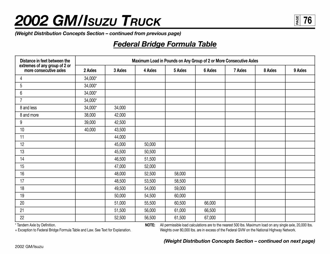
2002 GM/Isuzu
2002 GM/ISUZU TRUCK 76PA
GE
(Weight Distribution Concepts Section – continued from previous page)
Federal Bridge Formula Table
Distance in feet between the Maximum Load in Pounds on Any Group of 2 or More Consecutive Axlesextremes of any group of 2 or
more consecutive axles 2 Axles 3 Axles 4 Axles 5 Axles 6 Axles 7 Axles 8 Axles 9 Axles
4 34,000*
5 34,000*
6 34,000*
7 34,000*
8 and less 34,000* 34,000
8 and more 38,000 42,000
9 39,000 42,500
10 40,000 43,500
11 44,000
12 45,000 50,000
13 45,500 50,500
14 46,500 51,500
15 47,000 52,000
16 48,000 52,500 58,000
17 48,500 53,500 58,500
18 49,500 54,000 59,000
19 50,000 54,500 60,000
20 51,000 55,500 60,500 66,000
21 51,500 56,000 61,000 66,500
22 52,500 56,500 61,500 67,000* Tandem Axle by Definition. NOTE: All permissible load calculations are to the nearest 500 lbs. Maximum load on any single axle, 20,000 lbs.+ Exception to Federal Bridge Formula Table and Law. See Text for Explanation. Weights over 80,000 lbs. are in excess of the Federal GVW on the National Highway Network.
(Weight Distribution Concepts Section – continued on next page)
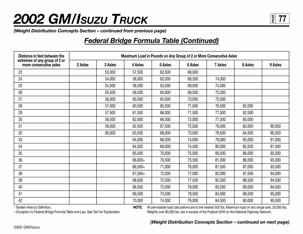
2002 GM/Isuzu
2002 GM/ISUZU TRUCK 77PA
GE
(Weight Distribution Concepts Section – continued from previous page)
Federal Bridge Formula Table (Continued)
Distance in feet between the Maximum Load in Pounds on Any Group of 2 or More Consecutive Axlesextremes of any group of 2 or
more consecutive axles 2 Axles 3 Axles 4 Axles 5 Axles 6 Axles 7 Axles 8 Axles 9 Axles
23 53,000 57,500 62,500 68,000
24 54,000 58,000 63,000 68,500 74,000
25 54,500 58,500 63,500 69,000 74,500
26 55,500 59,500 64,000 69,500 75,000
27 56,000 60,000 65,000 70,000 75,500
28 57,000 60,500 65,500 71,000 76,500 82,000
29 57,500 61,500 66,000 71,500 77,000 82,500
30 58,500 62,000 66,500 72,000 77,500 83,000
31 59,000 62,500 67,500 72,500 78,000 83,500 90,000
32 60,000 63,500 68,000 73,000 78,500 84,500 90,500
33 64,000 68,500 74,000 79,000 85,000 91,000
34 64,500 69,000 74,500 80,000 85,500 91,500
35 65,500 70,000 75,000 80,500 86,000 92,000
36 66,000+ 70,500 75,500 81,000 86,500 93,000
37 66,500+ 71,000 76,000 81,500 87,000 93,500
38 67,500+ 72,000 77,000 82,000 87,500 94,000
39 68,000 72,500 77,500 82,500 88,500 94,500
40 68,500 73,000 78,000 83,500 89,000 94,500
41 69,500 73,500 78,500 84,000 89,500 95,000
42 70,000 74,000 79,000 84,500 90,000 95,500* Tandem Axle by Definition. NOTE: All permissible load calculations are to the nearest 500 lbs. Maximum load on any single axle, 20,000 lbs.+ Exception to Federal Bridge Formula Table and Law. See Text for Explanation. Weights over 80,000 lbs. are in excess of the Federal GVW on the National Highway Network.
(Weight Distribution Concepts Section – continued on next page)
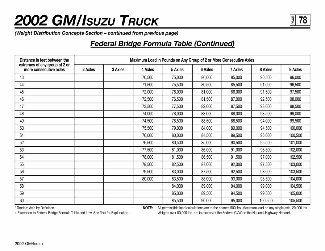
2002 GM/Isuzu
2002 GM/ISUZU TRUCK 78PA
GE
(Weight Distribution Concepts Section – continued from previous page)
Federal Bridge Formula Table (Continued)
Distance in feet between the Maximum Load in Pounds on Any Group of 2 or More Consecutive Axlesextremes of any group of 2 or
more consecutive axles 2 Axles 3 Axles 4 Axles 5 Axles 6 Axles 7 Axles 8 Axles 9 Axles
43 70,500 75,000 80,000 85,000 90,500 96,000
44 71,500 75,500 80,500 85,500 91,000 96,500
45 72,000 76,000 81,000 86,000 91,500 97,500
46 72,500 76,500 81,500 87,000 92,500 98,000
47 73,500 77,500 82,000 87,500 93,000 98,500
48 74,000 78,000 83,000 88,000 93,500 99,000
49 74,500 78,500 83,500 88,500 94,000 99,500
50 75,500 79,000 84,000 89,000 94,500 100,000
51 76,000 80,000 84,500 89,500 95,000 100,500
52 76,500 80,500 85,000 90,500 95,500 101,000
53 77,500 81,000 86,000 91,000 96,500 102,000
54 78,000 81,500 86,500 91,500 97,000 102,500
55 78,500 82,500 87,000 92,000 97,500 103,000
56 79,500 83,000 87,500 92,500 98,000 103,500
57 80,000 83,500 88,000 93,000 98,500 104,000
58 84,000 89,000 94,000 99,000 104,500
59 85,000 89,500 94,500 99,500 105,000
60 85,500 90,000 95,000 100,500 105,500* Tandem Axle by Definition. NOTE: All permissible load calculations are to the nearest 500 lbs. Maximum load on any single axle, 20,000 lbs.+ Exception to Federal Bridge Formula Table and Law. See Text for Explanation. Weights over 80,000 lbs. are in excess of the Federal GVW on the National Highway Network.
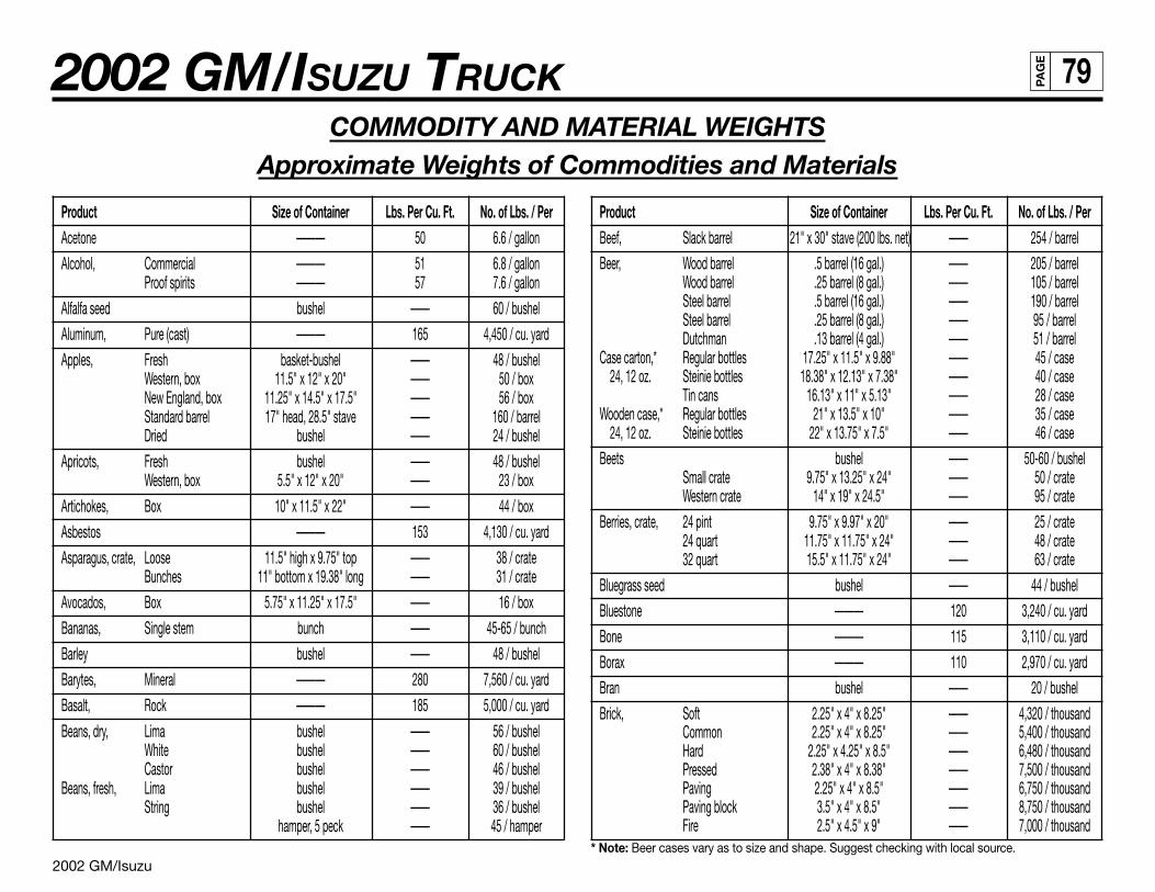
2002 GM/Isuzu
2002 GM/ISUZU TRUCK 79PA
GE
COMMODITY AND MATERIAL WEIGHTSApproximate Weights of Commodities and Materials
Product Size of Container Lbs. Per Cu. Ft. No. of Lbs. / PerAcetone ——— 50 6.6 / gallon
Alcohol, Commercial ——— 51 6.8 / gallonProof spirits ——— 57 7.6 / gallon
Alfalfa seed bushel —— 60 / bushel
Aluminum, Pure (cast) ——— 165 4,450 / cu. yard
Apples, Fresh basket-bushel —— 48 / bushelWestern, box 11.5" x 12" x 20" —— 50 / boxNew England, box 11.25" x 14.5" x 17.5" —— 56 / boxStandard barrel 17" head, 28.5" stave —— 160 / barrelDried bushel —— 24 / bushel
Apricots, Fresh bushel —— 48 / bushelWestern, box 5.5" x 12" x 20" —— 23 / box
Artichokes, Box 10" x 11.5" x 22" —— 44 / box
Asbestos ——— 153 4,130 / cu. yard
Asparagus, crate, Loose 11.5" high x 9.75" top —— 38 / crateBunches 11" bottom x 19.38" long —— 31 / crate
Avocados, Box 5.75" x 11.25" x 17.5" —— 16 / box
Bananas, Single stem bunch —— 45-65 / bunch
Barley bushel —— 48 / bushel
Barytes, Mineral ——— 280 7,560 / cu. yard
Basalt, Rock ——— 185 5,000 / cu. yard
Beans, dry, Lima bushel —— 56 / bushelWhite bushel —— 60 / bushelCastor bushel —— 46 / bushel
Beans, fresh, Lima bushel —— 39 / bushelString bushel —— 36 / bushel
hamper, 5 peck —— 45 / hamper
Product Size of Container Lbs. Per Cu. Ft. No. of Lbs. / PerBeef, Slack barrel 21" x 30" stave (200 lbs. net) —— 254 / barrel
Beer, Wood barrel .5 barrel (16 gal.) —— 205 / barrelWood barrel .25 barrel (8 gal.) —— 105 / barrelSteel barrel .5 barrel (16 gal.) —— 190 / barrelSteel barrel .25 barrel (8 gal.) —— 95 / barrelDutchman .13 barrel (4 gal.) —— 51 / barrel
Case carton,* Regular bottles 17.25" x 11.5" x 9.88" —— 45 / case24, 12 oz. Steinie bottles 18.38" x 12.13" x 7.38" —— 40 / case
Tin cans 16.13" x 11" x 5.13" —— 28 / caseWooden case,* Regular bottles 21" x 13.5" x 10" —— 35 / case
24, 12 oz. Steinie bottles 22" x 13.75" x 7.5" —— 46 / case
Beets bushel —— 50-60 / bushelSmall crate 9.75" x 13.25" x 24" —— 50 / crateWestern crate 14" x 19" x 24.5" —— 95 / crate
Berries, crate, 24 pint 9.75" x 9.97" x 20" —— 25 / crate24 quart 11.75" x 11.75" x 24" —— 48 / crate32 quart 15.5" x 11.75" x 24" —— 63 / crate
Bluegrass seed bushel —— 44 / bushel
Bluestone ——— 120 3,240 / cu. yard
Bone ——— 115 3,110 / cu. yard
Borax ——— 110 2,970 / cu. yard
Bran bushel —— 20 / bushel
Brick, Soft 2.25" x 4" x 8.25" —— 4,320 / thousandCommon 2.25" x 4" x 8.25" —— 5,400 / thousandHard 2.25" x 4.25" x 8.5" —— 6,480 / thousandPressed 2.38" x 4" x 8.38" —— 7,500 / thousandPaving 2.25" x 4" x 8.5" —— 6,750 / thousandPaving block 3.5" x 4" x 8.5" —— 8,750 / thousandFire 2.5" x 4.5" x 9" —— 7,000 / thousand
* Note: Beer cases vary as to size and shape. Suggest checking with local source.
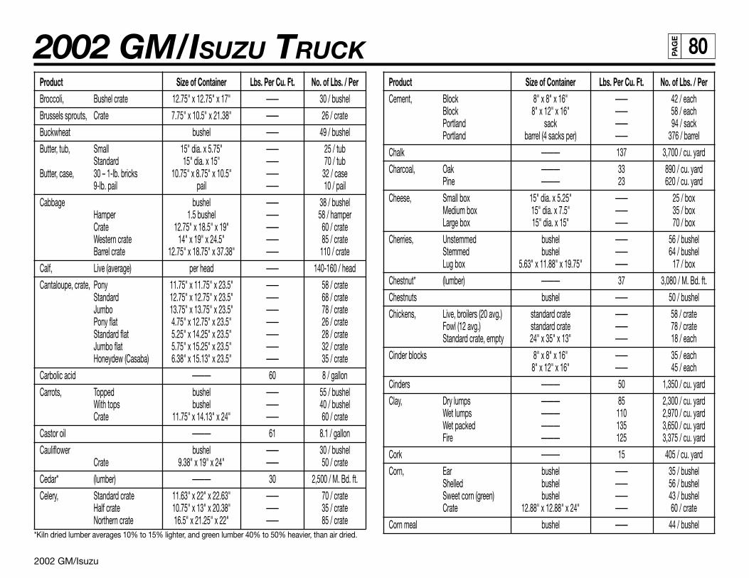
2002 GM/Isuzu
2002 GM/ISUZU TRUCK 80PA
GE
Product Size of Container Lbs. Per Cu. Ft. No. of Lbs. / PerBroccoli, Bushel crate 12.75" x 12.75" x 17" —— 30 / bushel
Brussels sprouts, Crate 7.75" x 10.5" x 21.38" —— 26 / crate
Buckwheat bushel —— 49 / bushel
Butter, tub, Small 15" dia. x 5.75" —— 25 / tubStandard 15" dia. x 15" —— 70 / tub
Butter, case, 30 – 1-lb. bricks 10.75" x 8.75" x 10.5" —— 32 / case9-lb. pail pail —— 10 / pail
Cabbage bushel —— 38 / bushelHamper 1.5 bushel —— 58 / hamperCrate 12.75" x 18.5" x 19" —— 60 / crateWestern crate 14" x 19" x 24.5" —— 85 / crateBarrel crate 12.75" x 18.75" x 37.38" —— 110 / crate
Calf, Live (average) per head —— 140-160 / head
Cantaloupe, crate, Pony 11.75" x 11.75" x 23.5" —— 58 / crateStandard 12.75" x 12.75" x 23.5" —— 68 / crateJumbo 13.75" x 13.75" x 23.5" —— 78 / cratePony flat 4.75" x 12.75" x 23.5" —— 26 / crateStandard flat 5.25" x 14.25" x 23.5" —— 28 / crateJumbo flat 5.75" x 15.25" x 23.5" —— 32 / crateHoneydew (Casaba) 6.38" x 15.13" x 23.5" —— 35 / crate
Carbolic acid ——— 60 8 / gallon
Carrots, Topped bushel —— 55 / bushelWith tops bushel —— 40 / bushelCrate 11.75" x 14.13" x 24" —— 60 / crate
Castor oil ——— 61 8.1 / gallon
Cauliflower bushel —— 30 / bushelCrate 9.38" x 19" x 24" —— 50 / crate
Cedar* (lumber) ——— 30 2,500 / M. Bd. ft.
Celery, Standard crate 11.63" x 22" x 22.63" —— 70 / crateHalf crate 10.75" x 13" x 20.38" —— 35 / crateNorthern crate 16.5" x 21.25" x 22" —— 85 / crate
*Kiln dried lumber averages 10% to 15% lighter, and green lumber 40% to 50% heavier, than air dried.
Product Size of Container Lbs. Per Cu. Ft. No. of Lbs. / PerCement, Block 8" x 8" x 16" —— 42 / each
Block 8" x 12" x 16" —— 58 / eachPortland sack —— 94 / sackPortland barrel (4 sacks per) —— 376 / barrel
Chalk ——— 137 3,700 / cu. yard
Charcoal, Oak ——— 33 890 / cu. yardPine ——— 23 620 / cu. yard
Cheese, Small box 15" dia. x 5.25" —— 25 / boxMedium box 15" dia. x 7.5" —— 35 / boxLarge box 15" dia. x 15" —— 70 / box
Cherries, Unstemmed bushel —— 56 / bushelStemmed bushel —— 64 / bushelLug box 5.63" x 11.88" x 19.75" —— 17 / box
Chestnut* (lumber) ——— 37 3,080 / M. Bd. ft.
Chestnuts bushel —— 50 / bushel
Chickens, Live, broilers (20 avg.) standard crate —— 58 / crateFowl (12 avg.) standard crate —— 78 / crateStandard crate, empty 24" x 35" x 13" —— 18 / each
Cinder blocks 8" x 8" x 16" —— 35 / each8" x 12" x 16" —— 45 / each
Cinders ——— 50 1,350 / cu. yard
Clay, Dry lumps ——— 85 2,300 / cu. yardWet lumps ——— 110 2,970 / cu. yardWet packed ——— 135 3,650 / cu. yardFire ——— 125 3,375 / cu. yard
Cork ——— 15 405 / cu. yard
Corn, Ear bushel —— 35 / bushelShelled bushel —— 56 / bushelSweet corn (green) bushel —— 43 / bushelCrate 12.88" x 12.88" x 24" —— 60 / crate
Corn meal bushel —— 44 / bushel
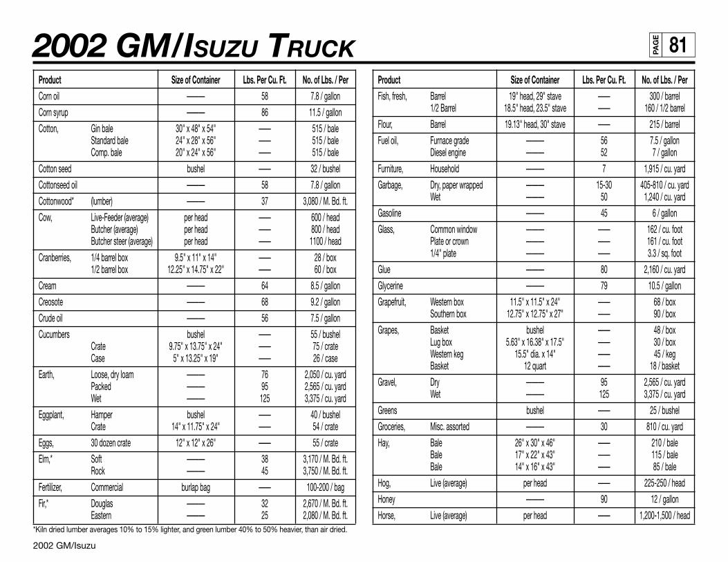
2002 GM/Isuzu
2002 GM/ISUZU TRUCK 81PA
GE
Product Size of Container Lbs. Per Cu. Ft. No. of Lbs. / PerCorn oil ——— 58 7.8 / gallon
Corn syrup ——— 86 11.5 / gallon
Cotton, Gin bale 30" x 48" x 54" —— 515 / baleStandard bale 24" x 28" x 56" —— 515 / baleComp. bale 20" x 24" x 56" —— 515 / bale
Cotton seed bushel —— 32 / bushel
Cottonseed oil ——— 58 7.8 / gallon
Cottonwood* (lumber) ——— 37 3,080 / M. Bd. ft.
Cow, Live-Feeder (average) per head —— 600 / headButcher (average) per head —— 800 / headButcher steer (average) per head —— 1100 / head
Cranberries, 1/4 barrel box 9.5" x 11" x 14" —— 28 / box1/2 barrel box 12.25" x 14.75" x 22" —— 60 / box
Cream ——— 64 8.5 / gallon
Creosote ——— 68 9.2 / gallon
Crude oil ——— 56 7.5 / gallon
Cucumbers bushel —— 55 / bushelCrate 9.75" x 13.75" x 24" —— 75 / crateCase 5" x 13.25" x 19" —— 26 / case
Earth, Loose, dry loam ——— 76 2,050 / cu. yardPacked ——— 95 2,565 / cu. yardWet ——— 125 3,375 / cu. yard
Eggplant, Hamper bushel —— 40 / bushelCrate 14" x 11.75" x 24" —— 54 / crate
Eggs, 30 dozen crate 12" x 12" x 26" —— 55 / crate
Elm,* Soft ——— 38 3,170 / M. Bd. ft.Rock ——— 45 3,750 / M. Bd. ft.
Fertilizer, Commercial burlap bag —— 100-200 / bag
Fir,* Douglas ——— 32 2,670 / M. Bd. ft.Eastern ——— 25 2,080 / M. Bd. ft.
*Kiln dried lumber averages 10% to 15% lighter, and green lumber 40% to 50% heavier, than air dried.
Product Size of Container Lbs. Per Cu. Ft. No. of Lbs. / PerFish, fresh, Barrel 19" head, 29" stave —— 300 / barrel
1/2 Barrel 18.5" head, 23.5" stave —— 160 / 1/2 barrel
Flour, Barrel 19.13" head, 30" stave —— 215 / barrel
Fuel oil, Furnace grade ——— 56 7.5 / gallonDiesel engine ——— 52 7 / gallon
Furniture, Household ——— 7 1,915 / cu. yard
Garbage, Dry, paper wrapped ——— 15-30 405-810 / cu. yardWet ——— 50 1,240 / cu. yard
Gasoline ——— 45 6 / gallon
Glass, Common window ——— —— 162 / cu. footPlate or crown ——— —— 161 / cu. foot1/4" plate ——— —— 3.3 / sq. foot
Glue ——— 80 2,160 / cu. yard
Glycerine ——— 79 10.5 / gallon
Grapefruit, Western box 11.5" x 11.5" x 24" —— 68 / boxSouthern box 12.75" x 12.75" x 27" —— 90 / box
Grapes, Basket bushel —— 48 / boxLug box 5.63" x 16.38" x 17.5" —— 30 / boxWestern keg 15.5" dia. x 14" —— 45 / kegBasket 12 quart —— 18 / basket
Gravel, Dry ——— 95 2,565 / cu. yardWet ——— 125 3,375 / cu. yard
Greens bushel —— 25 / bushel
Groceries, Misc. assorted ——— 30 810 / cu. yard
Hay, Bale 26" x 30" x 46" —— 210 / baleBale 17" x 22" x 43" —— 115 / baleBale 14" x 16" x 43" —— 85 / bale
Hog, Live (average) per head —— 225-250 / head
Honey ——— 90 12 / gallon
Horse, Live (average) per head —— 1,200-1,500 / head
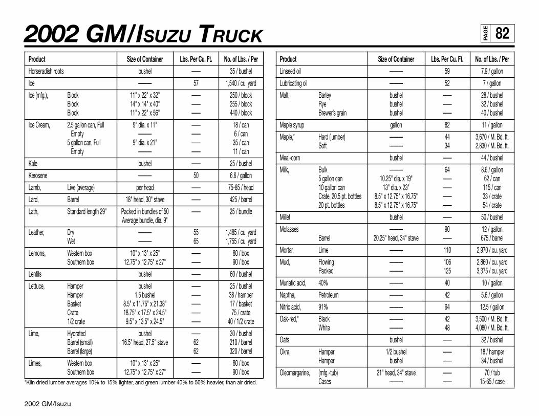
2002 GM/Isuzu
2002 GM/ISUZU TRUCK 82PA
GE
Product Size of Container Lbs. Per Cu. Ft. No. of Lbs. / PerHorseradish roots bushel —— 35 / bushel
Ice ——— 57 1,540 / cu. yard
Ice (mfg.), Block 11" x 22" x 32" —— 250 / blockBlock 14" x 14" x 40" —— 255 / blockBlock 11" x 22" x 56" —— 440 / block
Ice Cream, 2.5 gallon can, Full 9" dia. x 11" —— 18 / canEmpty ——— —— 6 / can
5 gallon can, Full 9" dia. x 21" —— 35 / canEmpty ——— —— 11 / can
Kale bushel —— 25 / bushel
Kerosene ——— 50 6.6 / gallon
Lamb, Live (average) per head —— 75-85 / head
Lard, Barrel 18" head, 30" stave —— 425 / barrel
Lath, Standard length 29" Packed in bundles of 50 —— 25 / bundleAverage bundle, dia. 9"
Leather, Dry ——— 55 1,485 / cu. yardWet ——— 65 1,755 / cu. yard
Lemons, Western box 10" x 13" x 25" —— 80 / boxSouthern box 12.75" x 12.75" x 27" —— 90 / box
Lentils bushel —— 60 / bushel
Lettuce, Hamper bushel —— 25 / bushelHamper 1.5 bushel —— 38 / hamperBasket 8.5" x 11.75" x 21.38" —— 17 / basketCrate 18.75" x 17.5" x 24.5" —— 75 / crate1/2 crate 9.5" x 13.5" x 24.5" —— 40 / 1/2 crate
Lime, Hydrated bushel —— 30 / bushelBarrel (small) 16.5" head, 27.5" stave 62 210 / barrelBarrel (large) 62 320 / barrel
Limes, Western box 10" x 13" x 25" —— 80 / boxSouthern box 12.75" x 12.75" x 27" —— 90 / box
*Kiln dried lumber averages 10% to 15% lighter, and green lumber 40% to 50% heavier, than air dried.
Product Size of Container Lbs. Per Cu. Ft. No. of Lbs. / PerLinseed oil ——— 59 7.9 / gallon
Lubricating oil ——— 52 7 / gallon
Malt, Barley bushel —— 28 / bushelRye bushel —— 32 / bushelBrewer’s grain bushel —— 40 / bushel
Maple syrup gallon 82 11 / gallon
Maple,* Hard (lumber) ——— 44 3,670 / M. Bd. ft.Soft ——— 34 2,830 / M. Bd. ft.
Meal-corn bushel —— 44 / bushel
Milk, Bulk ——— 64 8.6 / gallon5 gallon can 10.25" dia. x 19" —— 62 / can10 gallon can 13" dia. x 23" —— 115 / canCrate, 20.5 pt. bottles 8.5" x 12.75" x 16.75" —— 33 / crate20 pt. bottles 8.5" x 12.75" x 16.75" —— 54 / crate
Millet bushel —— 50 / bushel
Molasses ——— 90 12 / gallonBarrel 20.25" head, 34" stave —— 675 / barrel
Mortar, Lime ——— 110 2,970 / cu. yard
Mud, Flowing ——— 106 2,860 / cu. yardPacked ——— 125 3,375 / cu. yard
Muriatic acid, 40% ——— 40 10 / gallon
Naptha, Petroleum ——— 42 5.6 / gallon
Nitric acid, 91% ——— 94 12.5 / gallon
Oak-red,* Black ——— 42 3,500 / M. Bd. ft.White ——— 48 4,080 / M. Bd. ft.
Oats bushel —— 32 / bushel
Okra, Hamper 1/2 bushel —— 18 / hamperHamper bushel —— 34 / bushel
Oleomargarine, (mfg.-tub) 21" head, 34" stave —— 70 / tubCases ——— —— 15-65 / case
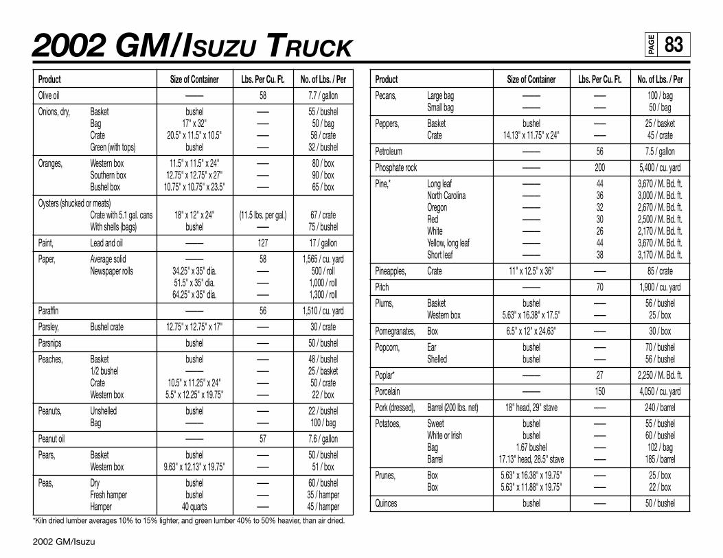
2002 GM/Isuzu
2002 GM/ISUZU TRUCK 83PA
GE
Product Size of Container Lbs. Per Cu. Ft. No. of Lbs. / PerOlive oil ——— 58 7.7 / gallon
Onions, dry, Basket bushel —— 55 / bushelBag 17" x 32" —— 50 / bagCrate 20.5" x 11.5" x 10.5" —— 58 / crateGreen (with tops) bushel —— 32 / bushel
Oranges, Western box 11.5" x 11.5" x 24" —— 80 / boxSouthern box 12.75" x 12.75" x 27" —— 90 / boxBushel box 10.75" x 10.75" x 23.5" —— 65 / box
Oysters (shucked or meats)Crate with 5.1 gal. cans 18" x 12" x 24" (11.5 lbs. per gal.) 67 / crateWith shells (bags) bushel —— 75 / bushel
Paint, Lead and oil ——— 127 17 / gallon
Paper, Average solid ——— 58 1,565 / cu. yardNewspaper rolls 34.25" x 35" dia. —— 500 / roll
51.5" x 35" dia. —— 1,000 / roll64.25" x 35" dia. —— 1,300 / roll
Paraffin ——— 56 1,510 / cu. yard
Parsley, Bushel crate 12.75" x 12.75" x 17" —— 30 / crate
Parsnips bushel —— 50 / bushel
Peaches, Basket bushel —— 48 / bushel1/2 bushel ——— —— 25 / basketCrate 10.5" x 11.25" x 24" —— 50 / crateWestern box 5.5" x 12.25" x 19.75" —— 22 / box
Peanuts, Unshelled bushel —— 22 / bushelBag ——— —— 100 / bag
Peanut oil ——— 57 7.6 / gallon
Pears, Basket bushel —— 50 / bushelWestern box 9.63" x 12.13" x 19.75" —— 51 / box
Peas, Dry bushel —— 60 / bushelFresh hamper bushel —— 35 / hamperHamper 40 quarts —— 45 / hamper
*Kiln dried lumber averages 10% to 15% lighter, and green lumber 40% to 50% heavier, than air dried.
Product Size of Container Lbs. Per Cu. Ft. No. of Lbs. / PerPecans, Large bag ——— —— 100 / bag
Small bag ——— —— 50 / bag
Peppers, Basket bushel —— 25 / basketCrate 14.13" x 11.75" x 24" —— 45 / crate
Petroleum ——— 56 7.5 / gallon
Phosphate rock ——— 200 5,400 / cu. yard
Pine,* Long leaf ——— 44 3,670 / M. Bd. ft.North Carolina ——— 36 3,000 / M. Bd. ft.Oregon ——— 32 2,670 / M. Bd. ft.Red ——— 30 2,500 / M. Bd. ft.White ——— 26 2,170 / M. Bd. ft.Yellow, long leaf ——— 44 3,670 / M. Bd. ft.Short leaf ——— 38 3,170 / M. Bd. ft.
Pineapples, Crate 11" x 12.5" x 36" —— 85 / crate
Pitch ——— 70 1,900 / cu. yard
Plums, Basket bushel —— 56 / bushelWestern box 5.63" x 16.38" x 17.5" —— 25 / box
Pomegranates, Box 6.5" x 12" x 24.63" —— 30 / box
Popcorn, Ear bushel —— 70 / bushelShelled bushel —— 56 / bushel
Poplar* ——— 27 2,250 / M. Bd. ft.
Porcelain ——— 150 4,050 / cu. yard
Pork (dressed), Barrel (200 lbs. net) 18" head, 29" stave —— 240 / barrel
Potatoes, Sweet bushel —— 55 / bushelWhite or Irish bushel —— 60 / bushelBag 1.67 bushel —— 102 / bagBarrel 17.13" head, 28.5" stave —— 185 / barrel
Prunes, Box 5.63" x 16.38" x 19.75" —— 25 / boxBox 5.63" x 11.88" x 19.75" —— 22 / box
Quinces bushel —— 50 / bushel
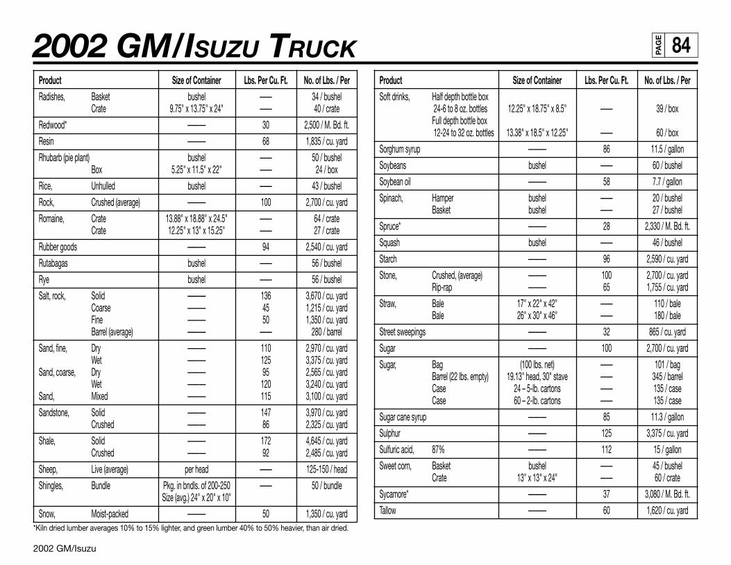
2002 GM/Isuzu
2002 GM/ISUZU TRUCK 84PA
GE
Product Size of Container Lbs. Per Cu. Ft. No. of Lbs. / PerRadishes, Basket bushel —— 34 / bushel
Crate 9.75" x 13.75" x 24" —— 40 / crate
Redwood* ——— 30 2,500 / M. Bd. ft.
Resin ——— 68 1,835 / cu. yard
Rhubarb (pie plant) bushel —— 50 / bushelBox 5.25" x 11.5" x 22" —— 24 / box
Rice, Unhulled bushel —— 43 / bushel
Rock, Crushed (average) ——— 100 2,700 / cu. yard
Romaine, Crate 13.88" x 18.88" x 24.5" —— 64 / crateCrate 12.25" x 13" x 15.25" —— 27 / crate
Rubber goods ——— 94 2,540 / cu. yard
Rutabagas bushel —— 56 / bushel
Rye bushel —— 56 / bushel
Salt, rock, Solid ——— 136 3,670 / cu. yardCoarse ——— 45 1,215 / cu. yardFine ——— 50 1,350 / cu. yardBarrel (average) ——— —— 280 / barrel
Sand, fine, Dry ——— 110 2,970 / cu. yardWet ——— 125 3,375 / cu. yard
Sand, coarse, Dry ——— 95 2,565 / cu. yardWet ——— 120 3,240 / cu. yard
Sand, Mixed ——— 115 3,100 / cu. yard
Sandstone, Solid ——— 147 3,970 / cu. yardCrushed ——— 86 2,325 / cu. yard
Shale, Solid ——— 172 4,645 / cu. yardCrushed ——— 92 2,485 / cu. yard
Sheep, Live (average) per head —— 125-150 / head
Shingles, Bundle Pkg. in bndls. of 200-250 —— 50 / bundleSize (avg.) 24" x 20" x 10"
Snow, Moist-packed ——— 50 1,350 / cu. yard*Kiln dried lumber averages 10% to 15% lighter, and green lumber 40% to 50% heavier, than air dried.
Product Size of Container Lbs. Per Cu. Ft. No. of Lbs. / PerSoft drinks, Half depth bottle box
24-6 to 8 oz. bottles 12.25" x 18.75" x 8.5" —— 39 / boxFull depth bottle box 12-24 to 32 oz. bottles 13.38" x 18.5" x 12.25" —— 60 / box
Sorghum syrup ——— 86 11.5 / gallon
Soybeans bushel —— 60 / bushel
Soybean oil ——— 58 7.7 / gallon
Spinach, Hamper bushel —— 20 / bushelBasket bushel —— 27 / bushel
Spruce* ——— 28 2,330 / M. Bd. ft.
Squash bushel —— 46 / bushel
Starch ——— 96 2,590 / cu. yard
Stone, Crushed, (average) ——— 100 2,700 / cu. yardRip-rap ——— 65 1,755 / cu. yard
Straw, Bale 17" x 22" x 42" —— 110 / baleBale 26" x 30" x 46" —— 180 / bale
Street sweepings ——— 32 865 / cu. yard
Sugar ——— 100 2,700 / cu. yard
Sugar, Bag (100 lbs. net) —— 101 / bagBarrel (22 lbs. empty) 19.13" head, 30" stave —— 345 / barrelCase 24 – 5-lb. cartons —— 135 / caseCase 60 – 2-lb. cartons —— 135 / case
Sugar cane syrup ——— 85 11.3 / gallon
Sulphur ——— 125 3,375 / cu. yard
Sulfuric acid, 87% ——— 112 15 / gallon
Sweet corn, Basket bushel —— 45 / bushelCrate 13" x 13" x 24" —— 60 / crate
Sycamore* ——— 37 3,080 / M. Bd. ft.
Tallow ——— 60 1,620 / cu. yard
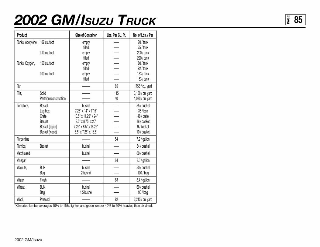
2002 GM/Isuzu
2002 GM/ISUZU TRUCK 85PA
GE
Product Size of Container Lbs. Per Cu. Ft. No. of Lbs. / PerTanks, Acetylene, 102 cu. foot empty —— 70 / tank
filled —— 75 / tank310 cu. foot empty —— 200 / tank
filled —— 220 / tankTanks, Oxygen, 150 cu. foot empty —— 80 / tank
filled —— 92 / tank300 cu. foot empty —— 133 / tank
filled —— 153 / tank
Tar ——— 65 1755 / cu. yard
Tile, Solid ——— 115 3,100 / cu. yardPartition (construction) ——— 40 1,080 / cu. yard
Tomatoes, Basket bushel —— 55 / bushelLug box 7.25" x 14" x 17.5" —— 35 / boxCrate 10.5" x 11.25" x 24" —— 48 / crateBasket 8.5" x 8.75" x 20" —— 18 / basketBasket (paper) 4.25" x 8.5" x 16.25" —— 9 / basketBasket (wood) 5.5" x 7.25" x 16.5" —— 10 / basket
Turpentine ——— 54 7.2 / gallon
Turnips, Basket bushel —— 54 / bushel
Vetch seed bushel —— 60 / bushel
Vinegar ——— 64 8.5 / gallon
Walnuts, Bulk bushel —— 50 / bushelBag 2 bushel —— 100 / bag
Water, Fresh ——— 63 8.4 / gallon
Wheat, Bulk bushel —— 60 / bushelBag 1.5 bushel —— 90 / bag
Wool, Pressed ——— 82 2,215 / cu. yard*Kiln dried lumber averages 10% to 15% lighter, and green lumber 40% to 50% heavier, than air dried.
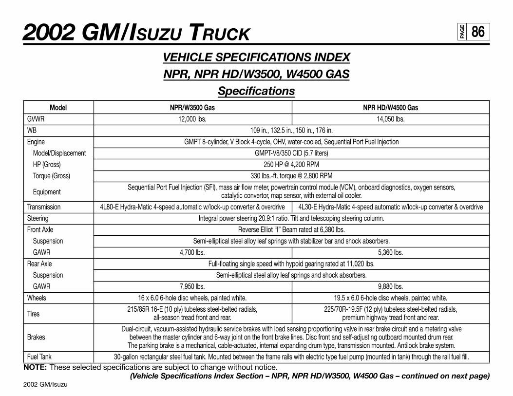
2002 GM/Isuzu
2002 GM/ISUZU TRUCK 86PA
GE
VEHICLE SPECIFICATIONS INDEXNPR, NPR HD/W3500, W4500 GAS
SpecificationsModel NPR/W3500 Gas NPR HD/W4500 Gas
GVWR 12,000 lbs. 14,050 lbs.
WB 109 in., 132.5 in., 150 in., 176 in.
Engine GMPT 8-cylinder, V Block 4-cycle, OHV, water-cooled, Sequential Port Fuel Injection
Model/Displacement GMPT-V8/350 CID (5.7 liters)
HP (Gross) 250 HP @ 4,200 RPM
Torque (Gross) 330 lbs.-ft. torque @ 2,800 RPM
EquipmentSequential Port Fuel Injection (SFI), mass air flow meter, powertrain control module (VCM), onboard diagnostics, oxygen sensors,
catalytic convertor, map sensor, with external oil cooler.
Transmission 4L80-E Hydra-Matic 4-speed automatic w/lock-up converter & overdrive 4L30-E Hydra-Matic 4-speed automatic w/lock-up converter & overdrive
Steering Integral power steering 20.9:1 ratio. Tilt and telescoping steering column.
Front Axle Reverse Elliot “I” Beam rated at 6,380 lbs.
Suspension Semi-elliptical steel alloy leaf springs with stabilizer bar and shock absorbers.
GAWR 4,700 lbs. 5,360 lbs.
Rear Axle Full-floating single speed with hypoid gearing rated at 11,020 lbs.
Suspension Semi-elliptical steel alloy leaf springs and shock absorbers.
GAWR 7,950 lbs. 9,880 lbs.
Wheels 16 x 6.0 6-hole disc wheels, painted white. 19.5 x 6.0 6-hole disc wheels, painted white.
Tires215/85R 16-E (10 ply) tubeless steel-belted radials, 225/70R-19.5F (12 ply) tubeless steel-belted radials,
all-season tread front and rear. premium highway tread front and rear.
Dual-circuit, vacuum-assisted hydraulic service brakes with load sensing proportioning valve in rear brake circuit and a metering valveBrakes between the master cylinder and 6-way joint on the front brake lines. Disc front and self-adjusting outboard mounted drum rear.
The parking brake is a mechanical, cable-actuated, internal expanding drum type, transmission mounted. Antilock brake system.
Fuel Tank 30-gallon rectangular steel fuel tank. Mounted between the frame rails with electric type fuel pump (mounted in tank) through the rail fuel fill.NOTE: These selected specifications are subject to change without notice.
(Vehicle Specifications Index Section – NPR, NPR HD/W3500, W4500 Gas – continued on next page)
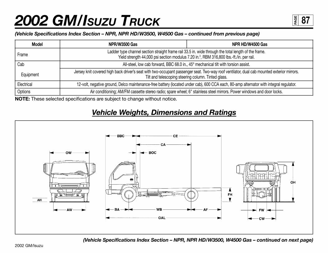
2002 GM/Isuzu
2002 GM/ISUZU TRUCK 87PA
GE
(Vehicle Specifications Index Section – NPR, NPR HD/W3500, W4500 Gas – continued from previous page)
Model NPR/W3500 Gas NPR HD/W4500 Gas
FrameLadder type channel section straight frame rail 33.5 in. wide through the total length of the frame.
Yield strength 44,000 psi section modulus 7.20 in.3, RBM 316,800 lbs.-ft./in. per rail.
Cab All-steel, low cab forward, BBC 68.0 in., 45º mechanical tilt with torsion assist.
EquipmentJersey knit covered high back driver’s seat with two-occupant passenger seat. Two-way roof ventilator, dual cab mounted exterior mirrors.
Tilt and telescoping steering column. Tinted glass.
Electrical 12-volt, negative ground, Delco maintenance-free battery (located under cab), 600 CCA each, 80-amp alternator with integral regulator.
Options Air conditioning; AM/FM cassette stereo radio; spare wheel; 6" stainless steel mirrors. Power windows and door locks.
NOTE: These selected specifications are subject to change without notice.
Vehicle Weights, Dimensions and Ratings
(Vehicle Specifications Index Section – NPR, NPR HD/W3500, W4500 Gas – continued on next page)
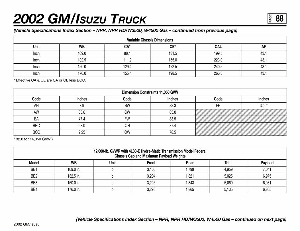
2002 GM/Isuzu
2002 GM/ISUZU TRUCK 88PA
GE
1234567890123456789012345678901212345678901234567890123456789012123456789123456789012345678901234567890121234567890123456789012345678901212345678912345678901234567890123456789012123456789012345678901234567890121234567891234567890123456789012345678901212345678901234567890123456789012123456789123456789012345678901234567890121234567890123456789012345678901212345678912345678901234567890123456789012123456789012345678901234567890121234567891234567890123456789012345678901212345678901234567890123456789012123456789123456789012345678901234567890121234567890123456789012345678901212345678912345678901234567890123456789012123456789012345678901234567890121234567891234567890123456789012345678901212345678901234567890123456789012123456789123456789012345678901234567890121234567890123456789012345678901212345678912345678901234567890123456789012123456789012345678901234567890121234567891234567890123456789012345678901212345678901234567890123456789012123456789123456789012345678901234567890121234567890123456789012345678901212345678912345678901234567890123456789012123456789012345678901234567890121234567891234567890123456789012345678901212345678901234567890123456789012123456789123456789012345678901234567890121234567890123456789012345678901212345678912345678901234567890123456789012123456789012345678901234567890121234567891234567890123456789012345678901212345678901234567890123456789012123456789123456789012345678901234567890121234567890123456789012345678901212345678912345678901234567890123456789012123456789012345678901234567890121234567891234567890123456789012345678901212345678901234567890123456789012123456789
(Vehicle Specifications Index Section – NPR, NPR HD/W3500, W4500 Gas – continued from previous page)
Variable Chassis DimensionsUnit WB CA* CE* OAL AFInch 109.0 88.4 131.5 199.5 43.1
Inch 132.5 111.9 155.0 223.0 43.1
Inch 150.0 129.4 172.5 240.5 43.1
Inch 176.0 155.4 198.5 266.3 43.1
* Effective CA & CE are CA or CE less BOC.
Dimension Constraints 11,050 GVWCode Inches Code Inches Code Inches
AH 7.9 BW 83.3 FH 32.0*
AW 65.6 CW 65.0
BA 47.4 FW 33.5
BBC 68.0 OH 87.4
BOC 9.25 OW 78.5
* 32.8 for 14,050 GVWR
12,000-lb. GVWR with 4L80-E Hydra-Matic Transmission Model FederalChassis Cab and Maximum Payload Weights
Model WB Unit Front Rear Total PayloadBB1 109.0 in. lb. 3,160 1,799 4,959 7,041
BB2 132.5 in. lb. 3,204 1,821 5,025 6,975
BB3 150.0 in. lb. 3,226 1,843 5,069 6,931
BB4 176.0 in. lb. 3,270 1,865 5,135 6,865
(Vehicle Specifications Index Section – NPR, NPR HD/W3500, W4500 Gas – continued on next page)
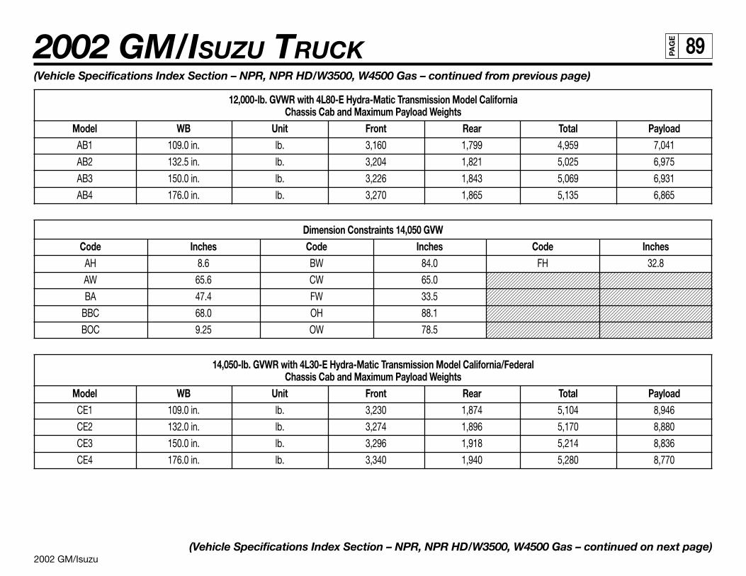
2002 GM/Isuzu
2002 GM/ISUZU TRUCK 89PA
GE
12345678901234567890123456789012123456789012345678901234567890121234567891234567890123456789012345678901212345678901234567890123456789012123456789123456789012345678901234567890121234567890123456789012345678901212345678912345678901234567890123456789012123456789012345678901234567890121234567891234567890123456789012345678901212345678901234567890123456789012123456789123456789012345678901234567890121234567890123456789012345678901212345678912345678901234567890123456789012123456789012345678901234567890121234567891234567890123456789012345678901212345678901234567890123456789012123456789123456789012345678901234567890121234567890123456789012345678901212345678912345678901234567890123456789012123456789012345678901234567890121234567891234567890123456789012345678901212345678901234567890123456789012123456789123456789012345678901234567890121234567890123456789012345678901212345678912345678901234567890123456789012123456789012345678901234567890121234567891234567890123456789012345678901212345678901234567890123456789012123456789123456789012345678901234567890121234567890123456789012345678901212345678912345678901234567890123456789012123456789012345678901234567890121234567891234567890123456789012345678901212345678901234567890123456789012123456789123456789012345678901234567890121234567890123456789012345678901212345678912345678901234567890123456789012123456789012345678901234567890121234567891234567890123456789012345678901212345678901234567890123456789012123456789123456789012345678901234567890121234567890123456789012345678901212345678912345678901234567890123456789012123456789012345678901234567890121234567891234567890123456789012345678901212345678901234567890123456789012123456789
(Vehicle Specifications Index Section – NPR, NPR HD/W3500, W4500 Gas – continued from previous page)
12,000-lb. GVWR with 4L80-E Hydra-Matic Transmission Model CaliforniaChassis Cab and Maximum Payload Weights
Model WB Unit Front Rear Total PayloadAB1 109.0 in. lb. 3,160 1,799 4,959 7,041
AB2 132.5 in. lb. 3,204 1,821 5,025 6,975
AB3 150.0 in. lb. 3,226 1,843 5,069 6,931
AB4 176.0 in. lb. 3,270 1,865 5,135 6,865
Dimension Constraints 14,050 GVWCode Inches Code Inches Code Inches
AH 8.6 BW 84.0 FH 32.8
AW 65.6 CW 65.0
BA 47.4 FW 33.5
BBC 68.0 OH 88.1
BOC 9.25 OW 78.5
14,050-lb. GVWR with 4L30-E Hydra-Matic Transmission Model California/FederalChassis Cab and Maximum Payload Weights
Model WB Unit Front Rear Total PayloadCE1 109.0 in. lb. 3,230 1,874 5,104 8,946
CE2 132.0 in. lb. 3,274 1,896 5,170 8,880
CE3 150.0 in. lb. 3,296 1,918 5,214 8,836
CE4 176.0 in. lb. 3,340 1,940 5,280 8,770
(Vehicle Specifications Index Section – NPR, NPR HD/W3500, W4500 Gas – continued on next page)
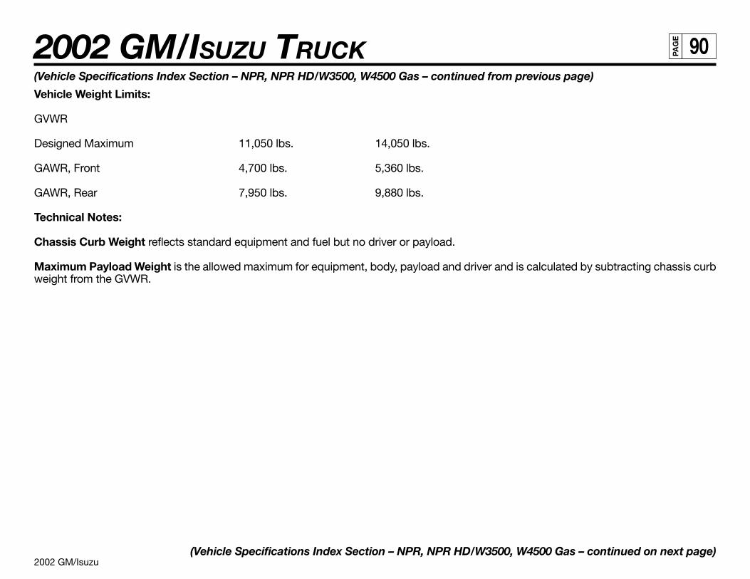
2002 GM/Isuzu
2002 GM/ISUZU TRUCK 90PA
GE
(Vehicle Specifications Index Section – NPR, NPR HD/W3500, W4500 Gas – continued from previous page)
Vehicle Weight Limits:
GVWR
Designed Maximum 11,050 lbs. 14,050 lbs.
GAWR, Front 4,700 lbs. 5,360 lbs.
GAWR, Rear 7,950 lbs. 9,880 lbs.
Technical Notes:
Chassis Curb Weight reflects standard equipment and fuel but no driver or payload.
Maximum Payload Weight is the allowed maximum for equipment, body, payload and driver and is calculated by subtracting chassis curbweight from the GVWR.
(Vehicle Specifications Index Section – NPR, NPR HD/W3500, W4500 Gas – continued on next page)
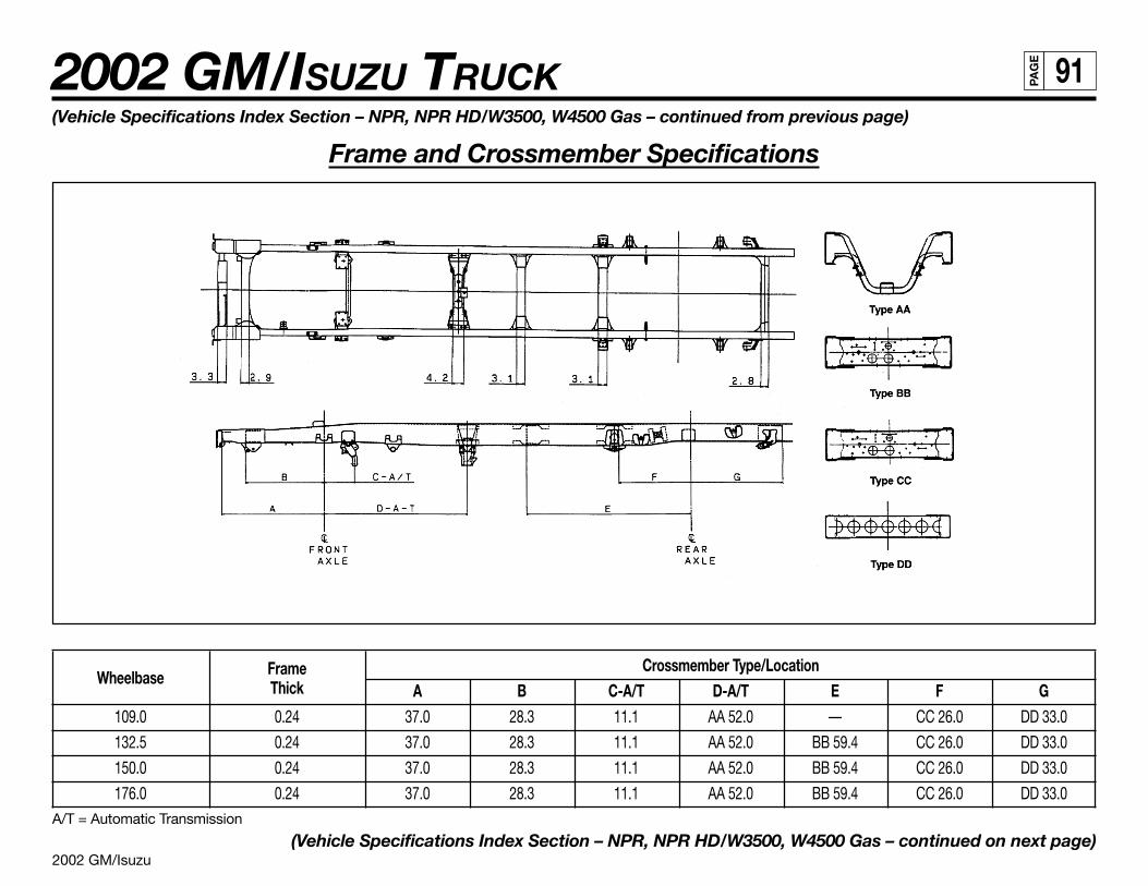
2002 GM/Isuzu
2002 GM/ISUZU TRUCK 91PA
GE
Wheelbase Frame Crossmember Type/LocationThick A B C-A/T D-A/T E F G
109.0 0.24 37.0 28.3 11.1 AA 52.0 — CC 26.0 DD 33.0
132.5 0.24 37.0 28.3 11.1 AA 52.0 BB 59.4 CC 26.0 DD 33.0
150.0 0.24 37.0 28.3 11.1 AA 52.0 BB 59.4 CC 26.0 DD 33.0
176.0 0.24 37.0 28.3 11.1 AA 52.0 BB 59.4 CC 26.0 DD 33.0A/T = Automatic Transmission
(Vehicle Specifications Index Section – NPR, NPR HD/W3500, W4500 Gas – continued on next page)
(Vehicle Specifications Index Section – NPR, NPR HD/W3500, W4500 Gas – continued from previous page)
Frame and Crossmember Specifications
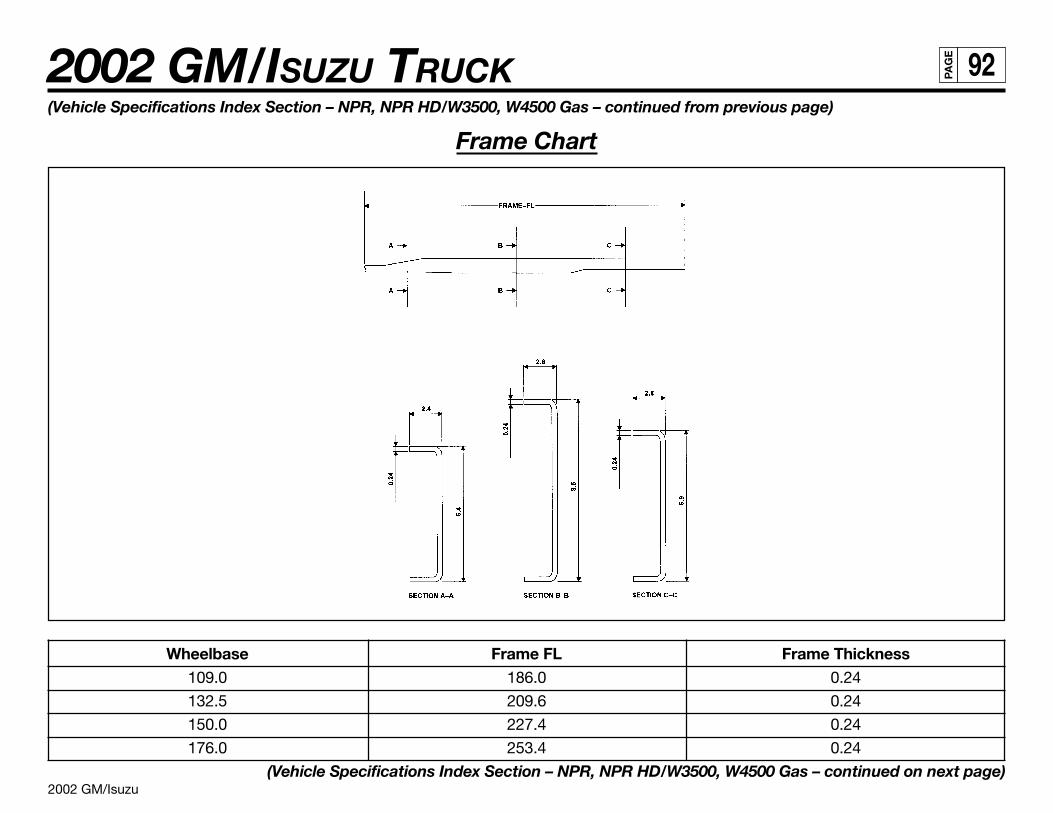
2002 GM/Isuzu
2002 GM/ISUZU TRUCK 92PA
GE
Wheelbase Frame FL Frame Thickness109.0 186.0 0.24
132.5 209.6 0.24
150.0 227.4 0.24
176.0 253.4 0.24
(Vehicle Specifications Index Section – NPR, NPR HD/W3500, W4500 Gas – continued on next page)
(Vehicle Specifications Index Section – NPR, NPR HD/W3500, W4500 Gas – continued from previous page)
Frame Chart
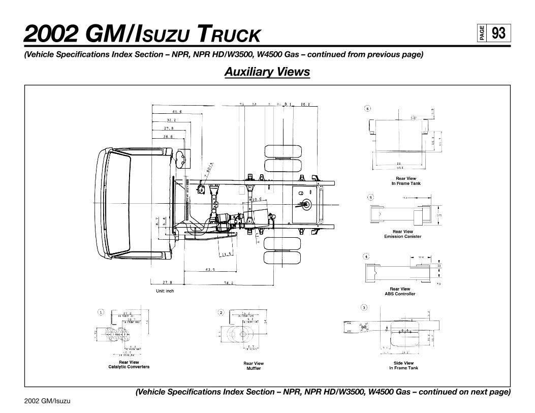
2002 GM/Isuzu
2002 GM/ISUZU TRUCK 93PA
GE
(Vehicle Specifications Index Section – NPR, NPR HD/W3500, W4500 Gas – continued from previous page)
Auxiliary Views
(Vehicle Specifications Index Section – NPR, NPR HD/W3500, W4500 Gas – continued on next page)
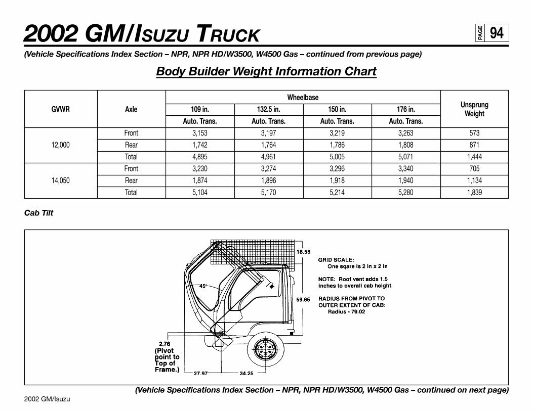
2002 GM/Isuzu
2002 GM/ISUZU TRUCK 94PA
GE
(Vehicle Specifications Index Section – NPR, NPR HD/W3500, W4500 Gas – continued from previous page)
Body Builder Weight Information Chart
WheelbaseUnsprungGVWR Axle 109 in. 132.5 in. 150 in. 176 in. Weight
Auto. Trans. Auto. Trans. Auto. Trans. Auto. Trans.Front 3,153 3,197 3,219 3,263 573
12,000 Rear 1,742 1,764 1,786 1,808 871
Total 4,895 4,961 5,005 5,071 1,444
Front 3,230 3,274 3,296 3,340 705
14,050 Rear 1,874 1,896 1,918 1,940 1,134
Total 5,104 5,170 5,214 5,280 1,839
Cab Tilt
(Vehicle Specifications Index Section – NPR, NPR HD/W3500, W4500 Gas – continued on next page)
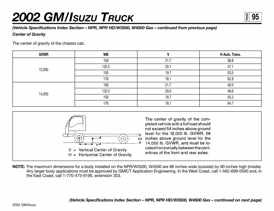
2002 GM/Isuzu
2002 GM/ISUZU TRUCK 95PA
GE
(Vehicle Specifications Index Section – NPR, NPR HD/W3500, W4500 Gas – continued from previous page)
Center of Gravity
The center of gravity of the chassis cab.
GVWR WB V H Auto. Trans.109 21.7 38.8
12,000132.5 20.1 47.1
150 19.7 53.5
176 18.1 62.8
109 21.7 40.0
14,050132.5 20.0 48.6
150 19.7 55.2
176 18.1 64.7
NOTE: The maximum dimensions for a body installed on the NPR/W3500, W4500 are 96 inches wide (outside) by 90 inches high (inside).Any larger body applications must be approved by GMICT Application Engineering. In the West Coast, call 1-562-699-0500 and, inthe East Coast, call 1-770-475-9195, extension 353.
(Vehicle Specifications Index Section – NPR, NPR HD/W3500, W4500 Gas – continued on next page)
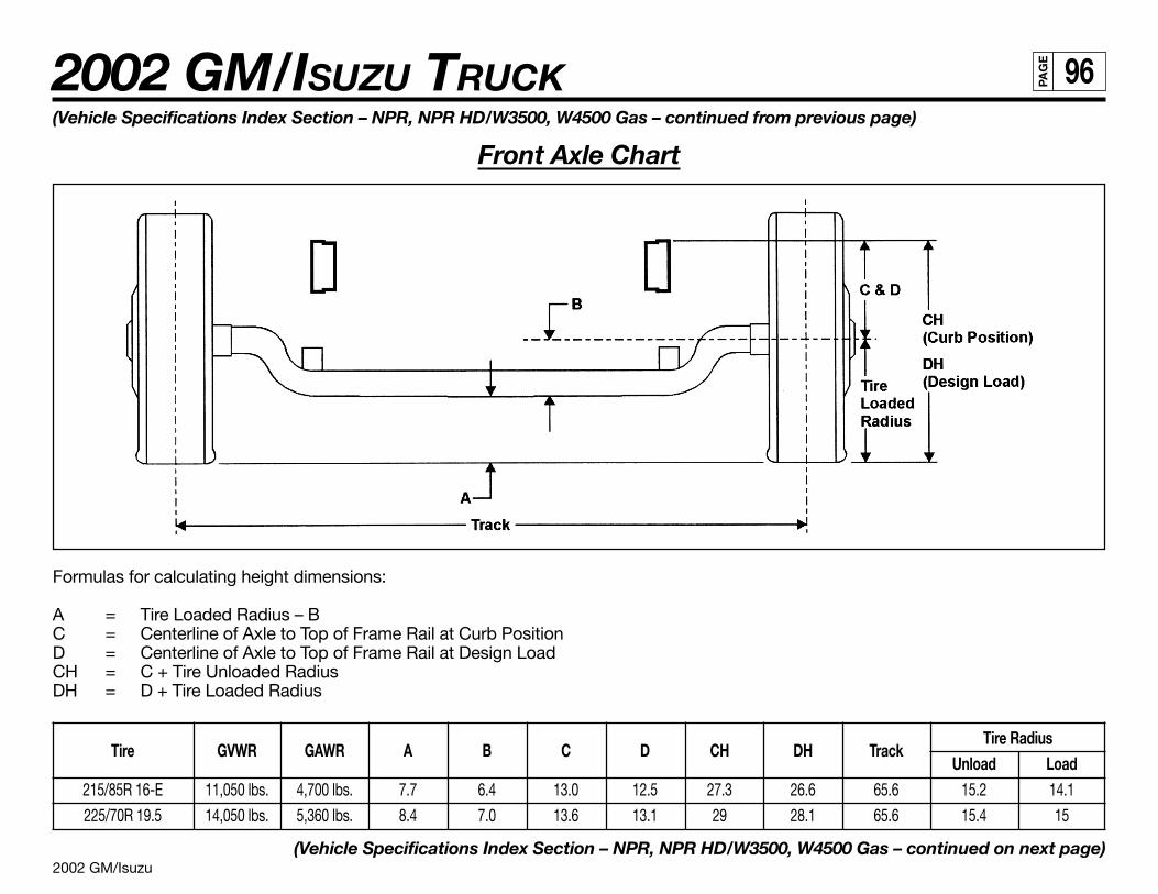
2002 GM/Isuzu
2002 GM/ISUZU TRUCK 96PA
GE
(Vehicle Specifications Index Section – NPR, NPR HD/W3500, W4500 Gas – continued from previous page)
Front Axle Chart
Formulas for calculating height dimensions:
A = Tire Loaded Radius – BC = Centerline of Axle to Top of Frame Rail at Curb PositionD = Centerline of Axle to Top of Frame Rail at Design LoadCH = C + Tire Unloaded RadiusDH = D + Tire Loaded Radius
Tire GVWR GAWR A B C D CH DH TrackTire Radius
Unload Load215/85R 16-E 11,050 lbs. 4,700 lbs. 7.7 6.4 13.0 12.5 27.3 26.6 65.6 15.2 14.1
225/70R 19.5 14,050 lbs. 5,360 lbs. 8.4 7.0 13.6 13.1 29 28.1 65.6 15.4 15
(Vehicle Specifications Index Section – NPR, NPR HD/W3500, W4500 Gas – continued on next page)
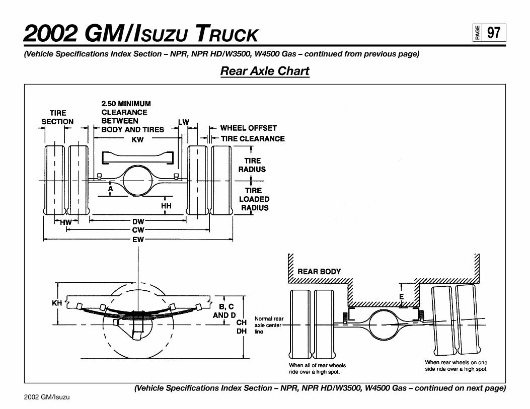
2002 GM/Isuzu
2002 GM/ISUZU TRUCK 97PA
GE
(Vehicle Specifications Index Section – NPR, NPR HD/W3500, W4500 Gas – continued from previous page)
Rear Axle Chart
(Vehicle Specifications Index Section – NPR, NPR HD/W3500, W4500 Gas – continued on next page)
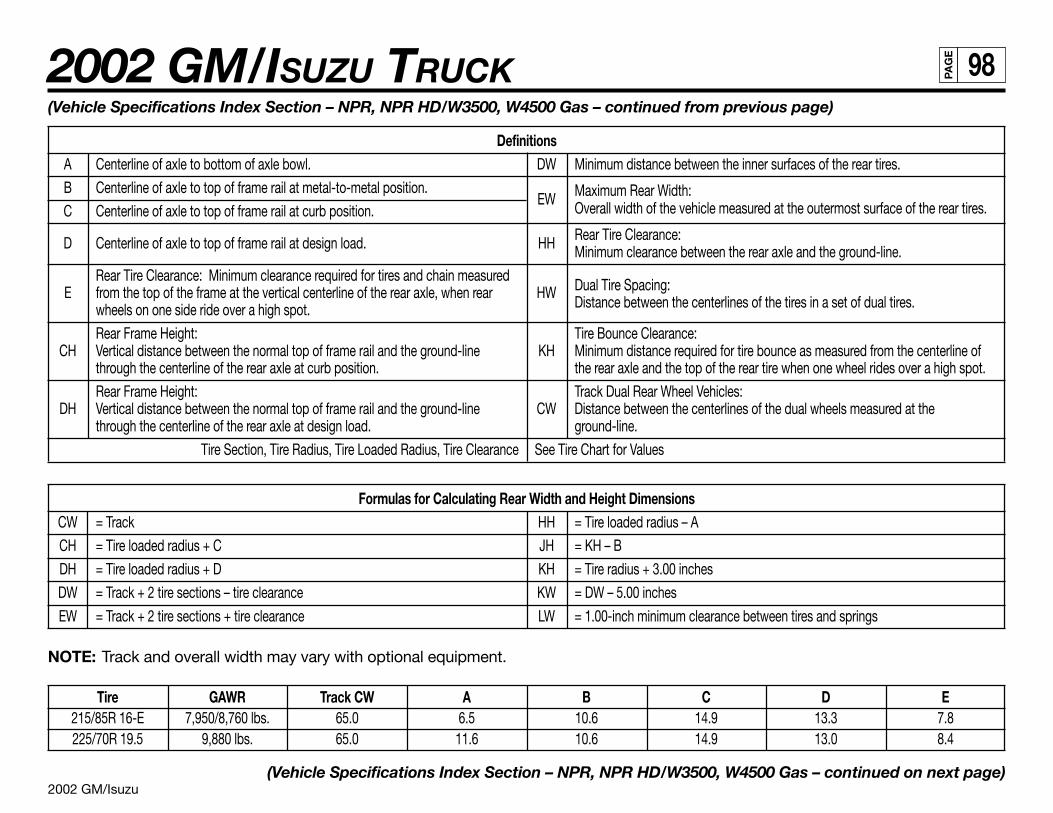
2002 GM/Isuzu
2002 GM/ISUZU TRUCK 98PA
GE
(Vehicle Specifications Index Section – NPR, NPR HD/W3500, W4500 Gas – continued from previous page)
DefinitionsA Centerline of axle to bottom of axle bowl. DW Minimum distance between the inner surfaces of the rear tires.
B Centerline of axle to top of frame rail at metal-to-metal position.EW Maximum Rear Width:
C Centerline of axle to top of frame rail at curb position. Overall width of the vehicle measured at the outermost surface of the rear tires.
D Centerline of axle to top of frame rail at design load. HH Rear Tire Clearance:Minimum clearance between the rear axle and the ground-line.
Rear Tire Clearance: Minimum clearance required for tires and chain measuredDual Tire Spacing:E from the top of the frame at the vertical centerline of the rear axle, when rear HWDistance between the centerlines of the tires in a set of dual tires.wheels on one side ride over a high spot.
Rear Frame Height: Tire Bounce Clearance:CH Vertical distance between the normal top of frame rail and the ground-line KH Minimum distance required for tire bounce as measured from the centerline of
through the centerline of the rear axle at curb position. the rear axle and the top of the rear tire when one wheel rides over a high spot.
Rear Frame Height: Track Dual Rear Wheel Vehicles:DH Vertical distance between the normal top of frame rail and the ground-line CW Distance between the centerlines of the dual wheels measured at the
through the centerline of the rear axle at design load. ground-line.
Tire Section, Tire Radius, Tire Loaded Radius, Tire Clearance See Tire Chart for Values
Formulas for Calculating Rear Width and Height DimensionsCW = Track HH = Tire loaded radius – A
CH = Tire loaded radius + C JH = KH – B
DH = Tire loaded radius + D KH = Tire radius + 3.00 inches
DW = Track + 2 tire sections – tire clearance KW = DW – 5.00 inches
EW = Track + 2 tire sections + tire clearance LW = 1.00-inch minimum clearance between tires and springs
NOTE: Track and overall width may vary with optional equipment.
Tire GAWR Track CW A B C D E215/85R 16-E 7,950/8,760 lbs. 65.0 6.5 10.6 14.9 13.3 7.8225/70R 19.5 9,880 lbs. 65.0 11.6 10.6 14.9 13.0 8.4
(Vehicle Specifications Index Section – NPR, NPR HD/W3500, W4500 Gas – continued on next page)
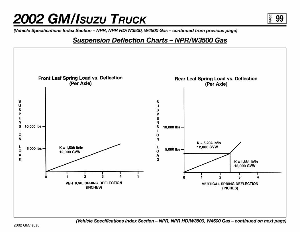
2002 GM/Isuzu
2002 GM/ISUZU TRUCK 99PA
GE
(Vehicle Specifications Index Section – NPR, NPR HD/W3500, W4500 Gas – continued from previous page)
Suspension Deflection Charts – NPR/W3500 Gas
(Vehicle Specifications Index Section – NPR, NPR HD/W3500, W4500 Gas – continued on next page)

2002 GM/Isuzu
2002 GM/ISUZU TRUCK 100PA
GE
(Vehicle Specifications Index Section – NPR, NPR HD/W3500, W4500 Gas – continued from previous page)
Suspension Deflection Charts – NPR HD/W4500 Gas
(Vehicle Specifications Index Section – NPR, NPR HD/W3500, W4500 Gas – continued on next page)
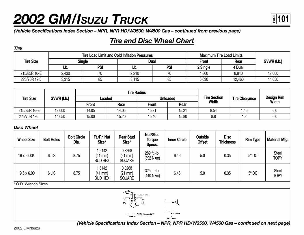
2002 GM/Isuzu
2002 GM/ISUZU TRUCK 101PA
GE
(Vehicle Specifications Index Section – NPR, NPR HD/W3500, W4500 Gas – continued from previous page)
Tire and Disc Wheel ChartTire
Tire Load Limit and Cold Inflation Pressures Maximum Tire Load LimitsTire Size Single Dual Front Rear GVWR (Lb.)
Lb. PSI Lb. PSI 2 Single 4 Dual215/85R 16-E 2,430 70 2,210 70 4,860 8,840 12,000225/70R 19.5 3,315 85 3,115 85 6,630 12,460 14,050
Tire RadiusTire Section Design RimTire Size GVWR (Lb.) Loaded Unloaded
WidthTire Clearance
WidthFront Rear Front Rear215/85R 16-E 12,000 14.05 14.05 15.21 15.21 8.54 1.46 6.0225/70R 19.5 14,050 15.00 15.20 15.40 15.80 8.8 1.2 6.0
Disc Wheel
Bolt Circle Ft./Rr. Nut Rear Stud Nut/Stud Outside DiscWheel Size Bolt Holes Dia. Size* Size* Torque Inner Circle Offset Thickness Rim Type Material Mfg.Specs.
1.6142 0.8268 289 ft.-lb. Steel16 x 6.00K 6 JIS 8.75 (41 mm) (21 mm) (392 N•m) 6.46 5.0 0.35 5º DC TOPYBUD HEX SQUARE
1.6142 0.8268 325 ft.-lb. Steel19.5 x 6.00 6 JIS 8.75 (41 mm) (21 mm) (440 N•m) 6.46 5.0 0.35 5º DC TOPYBUD HEX SQUARE* O.D. Wrench Sizes
(Vehicle Specifications Index Section – NPR, NPR HD/W3500, W4500 Gas – continued on next page)
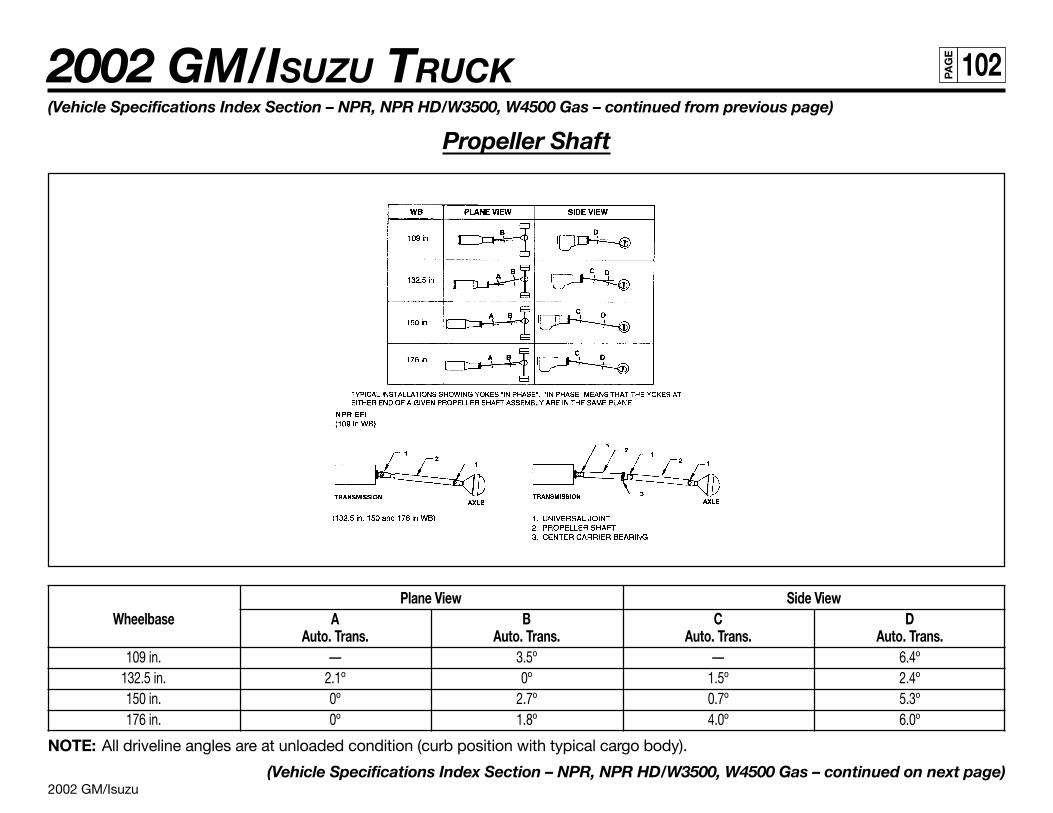
2002 GM/Isuzu
2002 GM/ISUZU TRUCK 102PA
GE
Plane View Side ViewWheelbase A B C D
Auto. Trans. Auto. Trans. Auto. Trans. Auto. Trans.109 in. — 3.5º — 6.4º
132.5 in. 2.1º 0º 1.5º 2.4º150 in. 0º 2.7º 0.7º 5.3º176 in. 0º 1.8º 4.0º 6.0º
NOTE: All driveline angles are at unloaded condition (curb position with typical cargo body).
(Vehicle Specifications Index Section – NPR, NPR HD/W3500, W4500 Gas – continued on next page)
(Vehicle Specifications Index Section – NPR, NPR HD/W3500, W4500 Gas – continued from previous page)
Propeller Shaft
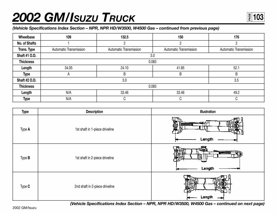
2002 GM/Isuzu
2002 GM/ISUZU TRUCK 103PA
GE
(Vehicle Specifications Index Section – NPR, NPR HD/W3500, W4500 Gas – continued from previous page)
Wheelbase 109 132.5 150 176No. of Shafts 1 2 2 2
Trans. Type Automatic Transmission Automatic Transmission Automatic Transmission Automatic Transmission
Shaft #1 O.D. 3.0
Thickness 0.083
Length 34.05 24.10 41.85 52.1
Type A B B B
Shaft #2 O.D. 3.0 3.5
Thickness 0.083
Length N/A 33.46 33.46 49.2
Type N/A C C C
Type Description Illustration
Type A 1st shaft in 1-piece driveline
Type B 1st shaft in 2-piece driveline
Type C 2nd shaft in 2-piece driveline
(Vehicle Specifications Index Section – NPR, NPR HD/W3500, W4500 Gas – continued on next page)
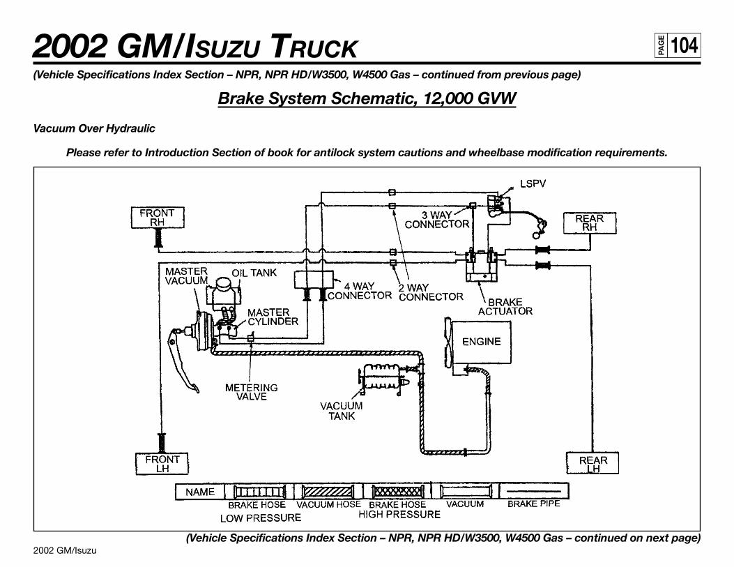
2002 GM/Isuzu
2002 GM/ISUZU TRUCK 104PA
GE
(Vehicle Specifications Index Section – NPR, NPR HD/W3500, W4500 Gas – continued from previous page)
Brake System Schematic, 12,000 GVW
Vacuum Over Hydraulic
Please refer to Introduction Section of book for antilock system cautions and wheelbase modification requirements.
(Vehicle Specifications Index Section – NPR, NPR HD/W3500, W4500 Gas – continued on next page)
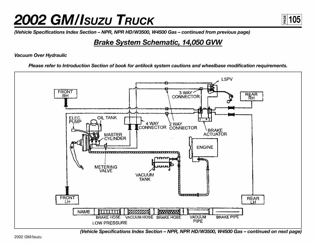
2002 GM/Isuzu
2002 GM/ISUZU TRUCK 105PA
GE
(Vehicle Specifications Index Section – NPR, NPR HD/W3500, W4500 Gas – continued from previous page)
Brake System Schematic, 14,050 GVW
Vacuum Over Hydraulic
Please refer to Introduction Section of book for antilock system cautions and wheelbase modification requirements.
(Vehicle Specifications Index Section – NPR, NPR HD/W3500, W4500 Gas – continued on next page)
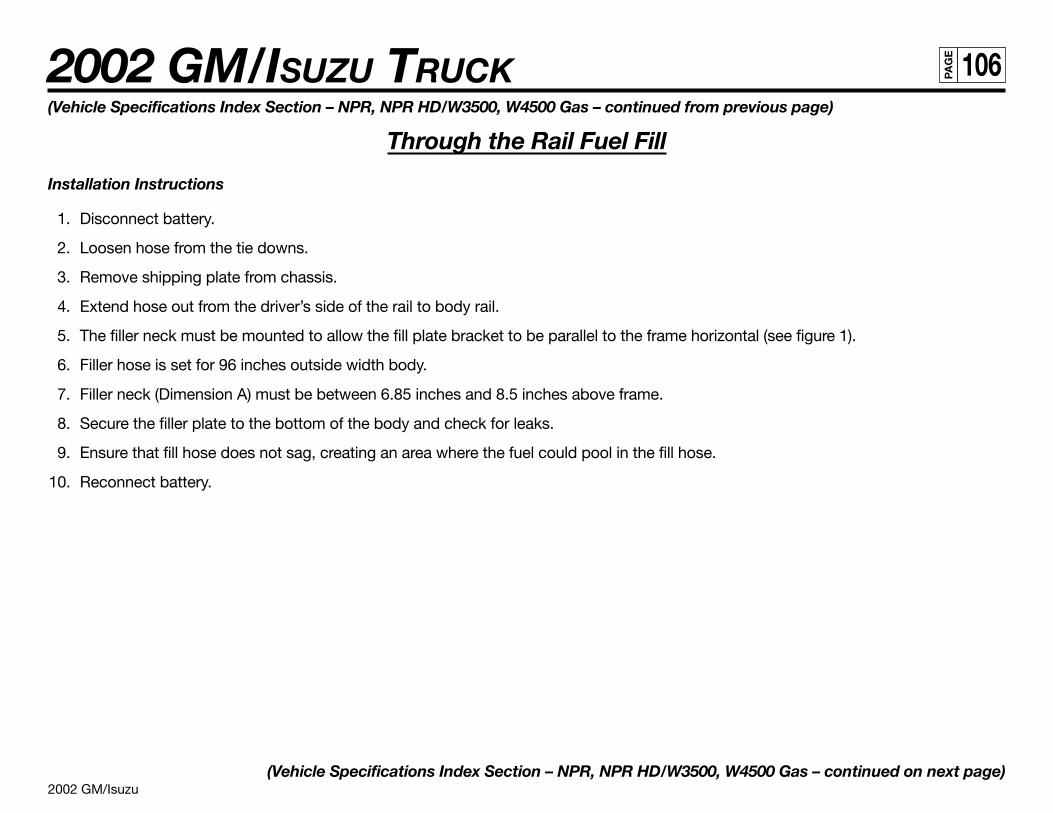
2002 GM/Isuzu
2002 GM/ISUZU TRUCK 106PA
GE
(Vehicle Specifications Index Section – NPR, NPR HD/W3500, W4500 Gas – continued from previous page)
Through the Rail Fuel Fill
Installation Instructions
1. Disconnect battery.
2. Loosen hose from the tie downs.
3. Remove shipping plate from chassis.
4. Extend hose out from the driver’s side of the rail to body rail.
5. The filler neck must be mounted to allow the fill plate bracket to be parallel to the frame horizontal (see figure 1).
6. Filler hose is set for 96 inches outside width body.
7. Filler neck (Dimension A) must be between 6.85 inches and 8.5 inches above frame.
8. Secure the filler plate to the bottom of the body and check for leaks.
9. Ensure that fill hose does not sag, creating an area where the fuel could pool in the fill hose.
10. Reconnect battery.
(Vehicle Specifications Index Section – NPR, NPR HD/W3500, W4500 Gas – continued on next page)
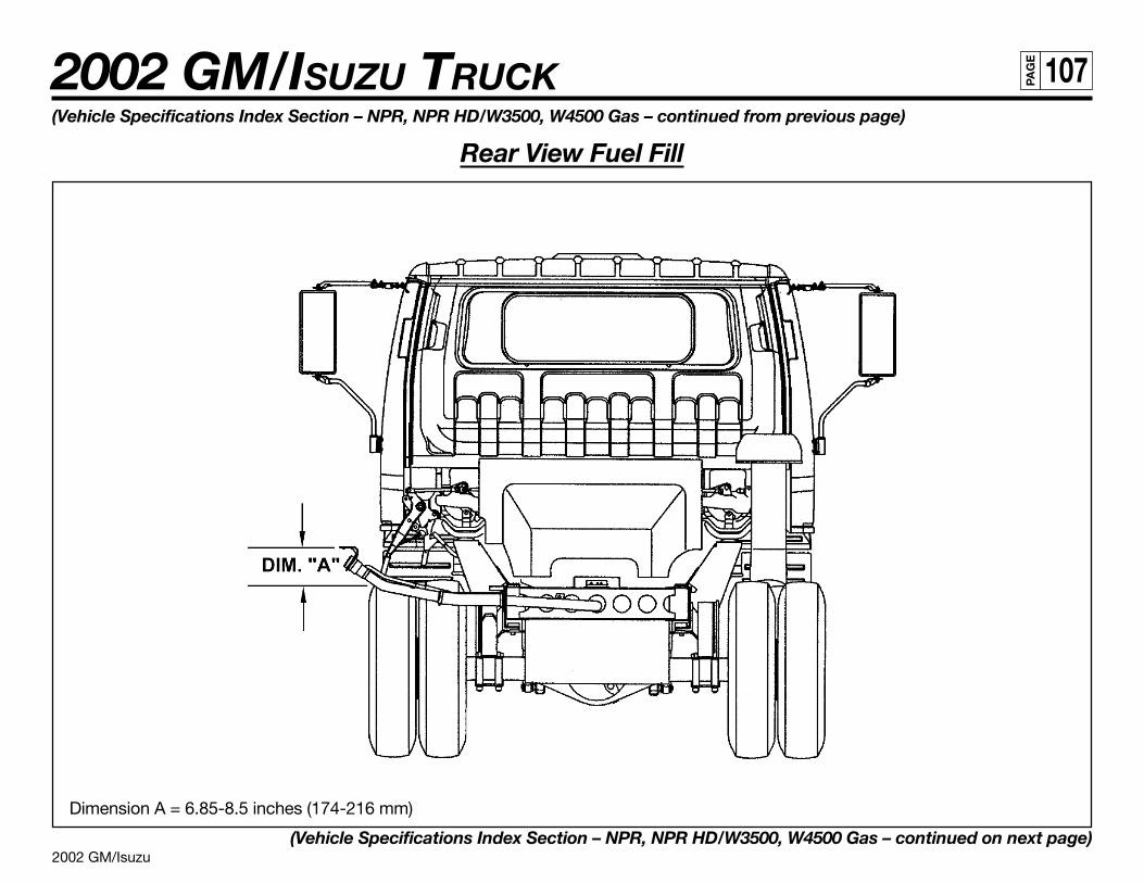
2002 GM/Isuzu
2002 GM/ISUZU TRUCK 107PA
GE
(Vehicle Specifications Index Section – NPR, NPR HD/W3500, W4500 Gas – continued from previous page)
Rear View Fuel Fill
Dimension A = 6.85-8.5 inches (174-216 mm)
(Vehicle Specifications Index Section – NPR, NPR HD/W3500, W4500 Gas – continued on next page)
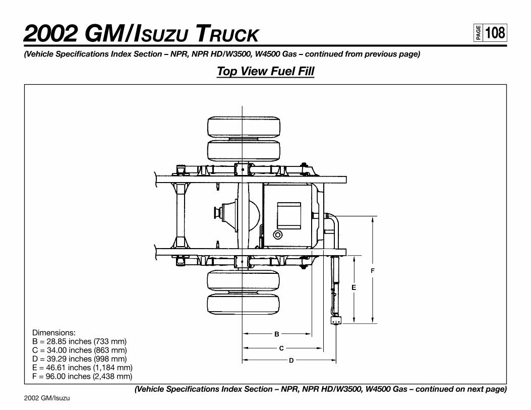
2002 GM/Isuzu
2002 GM/ISUZU TRUCK 108PA
GE
(Vehicle Specifications Index Section – NPR, NPR HD/W3500, W4500 Gas – continued from previous page)
Top View Fuel Fill
Dimensions:B = 28.85 inches (733 mm)C = 34.00 inches (863 mm)D = 39.29 inches (998 mm)E = 46.61 inches (1,184 mm)F = 96.00 inches (2,438 mm)
(Vehicle Specifications Index Section – NPR, NPR HD/W3500, W4500 Gas – continued on next page)
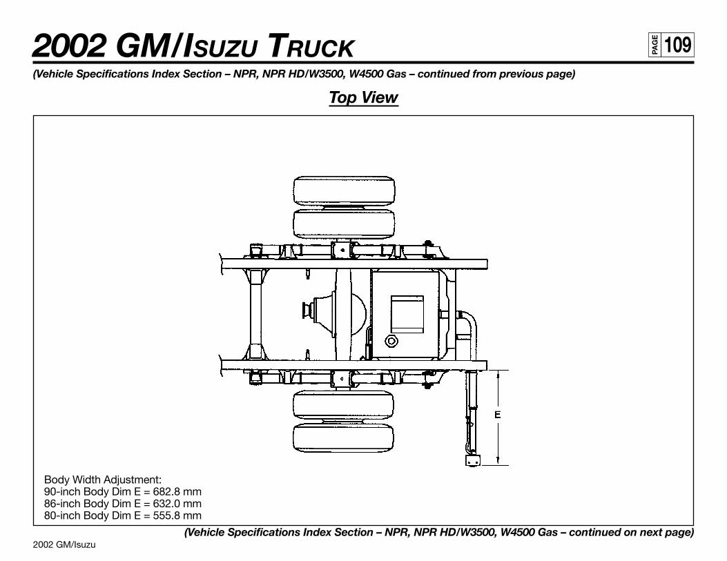
2002 GM/Isuzu
2002 GM/ISUZU TRUCK 109PA
GE
(Vehicle Specifications Index Section – NPR, NPR HD/W3500, W4500 Gas – continued from previous page)
Top View
Body Width Adjustment:90-inch Body Dim E = 682.8 mm86-inch Body Dim E = 632.0 mm80-inch Body Dim E = 555.8 mm
(Vehicle Specifications Index Section – NPR, NPR HD/W3500, W4500 Gas – continued on next page)
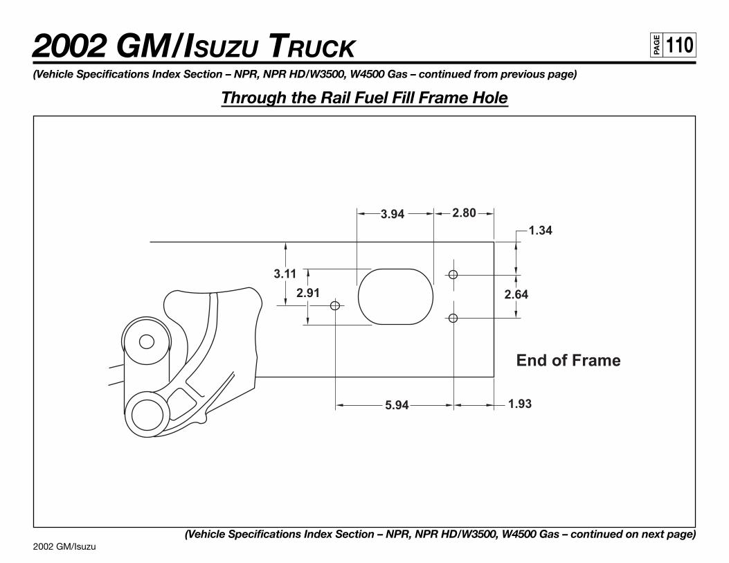
2002 GM/Isuzu
2002 GM/ISUZU TRUCK 110PA
GE
(Vehicle Specifications Index Section – NPR, NPR HD/W3500, W4500 Gas – continued from previous page)
Through the Rail Fuel Fill Frame Hole
(Vehicle Specifications Index Section – NPR, NPR HD/W3500, W4500 Gas – continued on next page)
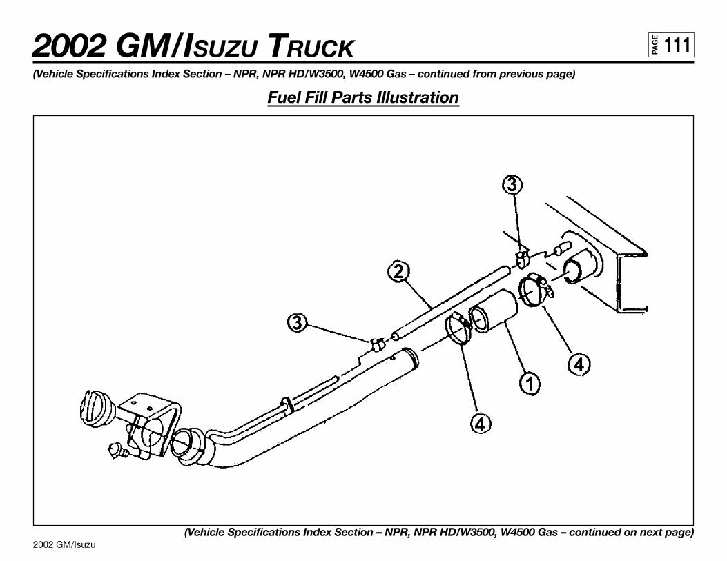
2002 GM/Isuzu
2002 GM/ISUZU TRUCK 111PA
GE
(Vehicle Specifications Index Section – NPR, NPR HD/W3500, W4500 Gas – continued from previous page)
Fuel Fill Parts Illustration
(Vehicle Specifications Index Section – NPR, NPR HD/W3500, W4500 Gas – continued on next page)
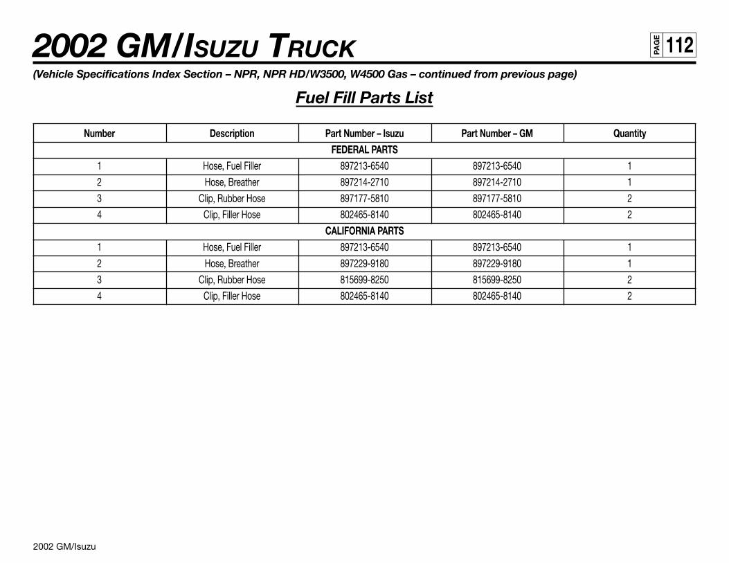
2002 GM/Isuzu
2002 GM/ISUZU TRUCK 112PA
GE
(Vehicle Specifications Index Section – NPR, NPR HD/W3500, W4500 Gas – continued from previous page)
Fuel Fill Parts List
Number Description Part Number – Isuzu Part Number – GM QuantityFEDERAL PARTS
1 Hose, Fuel Filler 897213-6540 897213-6540 1
2 Hose, Breather 897214-2710 897214-2710 1
3 Clip, Rubber Hose 897177-5810 897177-5810 2
4 Clip, Filler Hose 802465-8140 802465-8140 2
CALIFORNIA PARTS1 Hose, Fuel Filler 897213-6540 897213-6540 1
2 Hose, Breather 897229-9180 897229-9180 1
3 Clip, Rubber Hose 815699-8250 815699-8250 2
4 Clip, Filler Hose 802465-8140 802465-8140 2
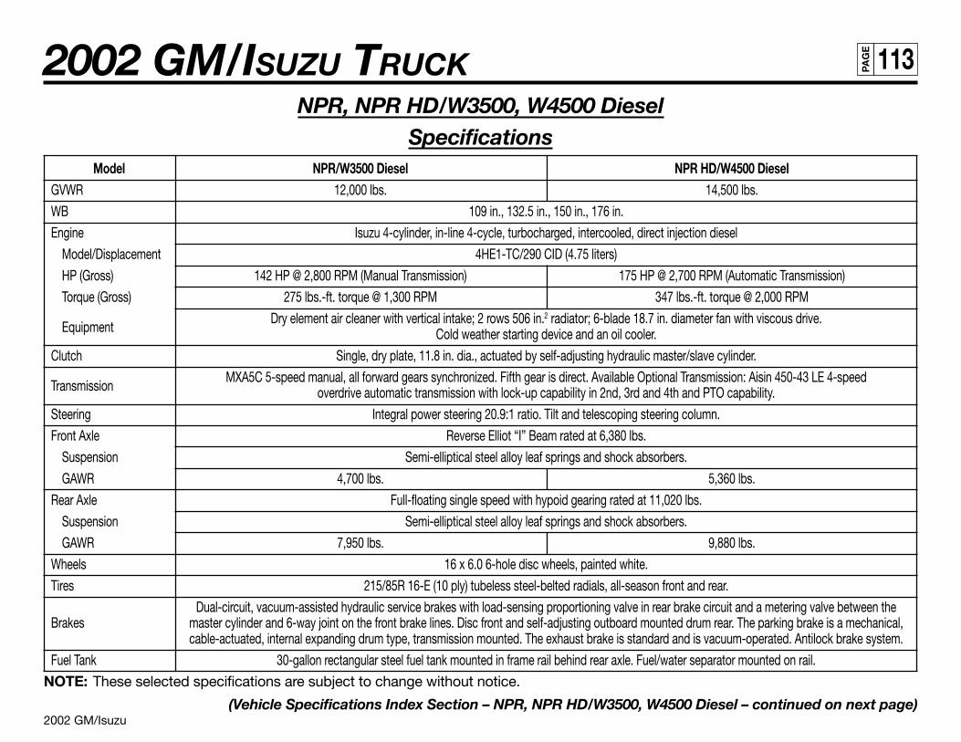
2002 GM/Isuzu
2002 GM/ISUZU TRUCK 113PA
GE
NPR, NPR HD/W3500, W4500 DieselSpecifications
Model NPR/W3500 Diesel NPR HD/W4500 DieselGVWR 12,000 lbs. 14,500 lbs.
WB 109 in., 132.5 in., 150 in., 176 in.
Engine Isuzu 4-cylinder, in-line 4-cycle, turbocharged, intercooled, direct injection diesel
Model/Displacement 4HE1-TC/290 CID (4.75 liters)
HP (Gross) 142 HP @ 2,800 RPM (Manual Transmission) 175 HP @ 2,700 RPM (Automatic Transmission)
Torque (Gross) 275 lbs.-ft. torque @ 1,300 RPM 347 lbs.-ft. torque @ 2,000 RPM
EquipmentDry element air cleaner with vertical intake; 2 rows 506 in.2 radiator; 6-blade 18.7 in. diameter fan with viscous drive.
Cold weather starting device and an oil cooler.
Clutch Single, dry plate, 11.8 in. dia., actuated by self-adjusting hydraulic master/slave cylinder.
TransmissionMXA5C 5-speed manual, all forward gears synchronized. Fifth gear is direct. Available Optional Transmission: Aisin 450-43 LE 4-speed
overdrive automatic transmission with lock-up capability in 2nd, 3rd and 4th and PTO capability.
Steering Integral power steering 20.9:1 ratio. Tilt and telescoping steering column.
Front Axle Reverse Elliot “I” Beam rated at 6,380 lbs.
Suspension Semi-elliptical steel alloy leaf springs and shock absorbers.
GAWR 4,700 lbs. 5,360 lbs.
Rear Axle Full-floating single speed with hypoid gearing rated at 11,020 lbs.
Suspension Semi-elliptical steel alloy leaf springs and shock absorbers.
GAWR 7,950 lbs. 9,880 lbs.
Wheels 16 x 6.0 6-hole disc wheels, painted white.
Tires 215/85R 16-E (10 ply) tubeless steel-belted radials, all-season front and rear.
Dual-circuit, vacuum-assisted hydraulic service brakes with load-sensing proportioning valve in rear brake circuit and a metering valve between theBrakes master cylinder and 6-way joint on the front brake lines. Disc front and self-adjusting outboard mounted drum rear. The parking brake is a mechanical,
cable-actuated, internal expanding drum type, transmission mounted. The exhaust brake is standard and is vacuum-operated. Antilock brake system.
Fuel Tank 30-gallon rectangular steel fuel tank mounted in frame rail behind rear axle. Fuel/water separator mounted on rail.
NOTE: These selected specifications are subject to change without notice.
(Vehicle Specifications Index Section – NPR, NPR HD/W3500, W4500 Diesel – continued on next page)
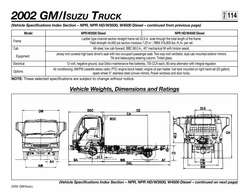
2002 GM/Isuzu
2002 GM/ISUZU TRUCK 114PA
GE
(Vehicle Specifications Index Section – NPR, NPR HD/W3500, W4500 Diesel – continued from previous page)
Model NPR/W3500 Diesel NPR HD/W4500 Diesel
FrameLadder type channel section straight frame rail 33.5 in. wide through the total length of the frame.
Yield strength 44,000 psi section modulus 7.20 in.3, RBM 316,800 lbs.-ft./in. per rail.
Cab All-steel, low cab forward, BBC 68.0 in., 45º mechanical tilt with torsion assist.
EquipmentJersey knit covered high back driver’s seat with two-occupant passenger seat. Two-way roof ventilator, dual cab mounted exterior mirrors.
Tilt and telescoping steering column. Tinted glass.
Electrical 12-volt, negative ground, dual Delco maintenance free batteries, 750 CCA each, 80-amp alternator with integral regulator.
OptionsAir conditioning; AM/FM cassette stereo radio; PTO; engine block heater; engine oil pan heater; fuel tank mounted on right hand rail (33 gallon);
spare wheel; 6" stainless steel convex mirrors. Power windows and door locks.
NOTE: These selected specifications are subject to change without notice.
Vehicle Weights, Dimensions and Ratings
(Vehicle Specifications Index Section – NPR, NPR HD/W3500, W4500 Diesel – continued on next page)
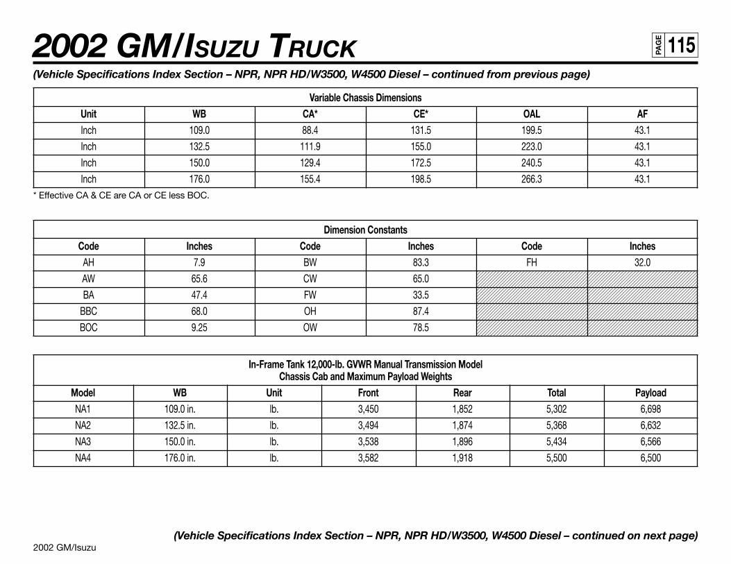
2002 GM/Isuzu
2002 GM/ISUZU TRUCK 115PA
GE
1234567890123456789012345678901212345678901234567890123456789012123456789123456789012345678901234567890121234567890123456789012345678901212345678912345678901234567890123456789012123456789012345678901234567890121234567891234567890123456789012345678901212345678901234567890123456789012123456789123456789012345678901234567890121234567890123456789012345678901212345678912345678901234567890123456789012123456789012345678901234567890121234567891234567890123456789012345678901212345678901234567890123456789012123456789123456789012345678901234567890121234567890123456789012345678901212345678912345678901234567890123456789012123456789012345678901234567890121234567891234567890123456789012345678901212345678901234567890123456789012123456789123456789012345678901234567890121234567890123456789012345678901212345678912345678901234567890123456789012123456789012345678901234567890121234567891234567890123456789012345678901212345678901234567890123456789012123456789123456789012345678901234567890121234567890123456789012345678901212345678912345678901234567890123456789012123456789012345678901234567890121234567891234567890123456789012345678901212345678901234567890123456789012123456789123456789012345678901234567890121234567890123456789012345678901212345678912345678901234567890123456789012123456789012345678901234567890121234567891234567890123456789012345678901212345678901234567890123456789012123456789123456789012345678901234567890121234567890123456789012345678901212345678912345678901234567890123456789012123456789012345678901234567890121234567891234567890123456789012345678901212345678901234567890123456789012123456789
(Vehicle Specifications Index Section – NPR, NPR HD/W3500, W4500 Diesel – continued from previous page)
Variable Chassis DimensionsUnit WB CA* CE* OAL AFInch 109.0 88.4 131.5 199.5 43.1
Inch 132.5 111.9 155.0 223.0 43.1
Inch 150.0 129.4 172.5 240.5 43.1
Inch 176.0 155.4 198.5 266.3 43.1* Effective CA & CE are CA or CE less BOC.
Dimension ConstantsCode Inches Code Inches Code Inches
AH 7.9 BW 83.3 FH 32.0
AW 65.6 CW 65.0
BA 47.4 FW 33.5
BBC 68.0 OH 87.4
BOC 9.25 OW 78.5
In-Frame Tank 12,000-lb. GVWR Manual Transmission ModelChassis Cab and Maximum Payload Weights
Model WB Unit Front Rear Total PayloadNA1 109.0 in. lb. 3,450 1,852 5,302 6,698
NA2 132.5 in. lb. 3,494 1,874 5,368 6,632
NA3 150.0 in. lb. 3,538 1,896 5,434 6,566
NA4 176.0 in. lb. 3,582 1,918 5,500 6,500
(Vehicle Specifications Index Section – NPR, NPR HD/W3500, W4500 Diesel – continued on next page)

2002 GM/Isuzu
2002 GM/ISUZU TRUCK 116PA
GE
(Vehicle Specifications Index Section – NPR, NPR HD/W3500, W4500 Diesel – continued from previous page)
In-Frame Tank 14,500-lb. GVWR Manual Transmission ModelChassis Cab and Maximum Payload Weights
Model WB Unit Front Rear Total PayloadNE1 109.0 in. lb. 3,461 1,852 5,313 9,187
NE2 132.5 in. lb. 3,505 1,874 5,379 9,121
NE3 150.0 in. lb. 3,549 1,896 5,445 9,055
NE4 176.0 in. lb. 3,593 1,918 5,511 8,989
In-Frame Tank 12,000-lb. GVWR Automatic Transmission ModelChassis Cab and Maximum Payload Weights
Model WB Unit Front Rear Total PayloadNB1 109.0 in. lb. 3,516 1,896 5,412 6,588
NB2 132.5 in. lb. 3,560 1,918 5,478 6,522
NB3 150.0 in. lb. 3,605 1,940 5,545 6,455
NB4 176.0 in. lb. 3,649 1,962 5,611 6,389
In-Frame Tank 14,500-lb. GVWR Automatic Transmission ModelChassis Cab and Maximum Payload Weights
Model WB Unit Front Rear Total PayloadNF1 109.0 in. lb. 3,527 1,896 5,423 9,077
NF2 132.5 in. lb. 3,571 1,918 5,489 9,011
NF3 150.0 in. lb. 3,616 1,940 5,556 8,944
NF4 176.0 in. lb. 3,660 1,962 5,622 8,878
(Vehicle Specifications Index Section – NPR, NPR HD/W3500, W4500 Diesel – continued on next page)
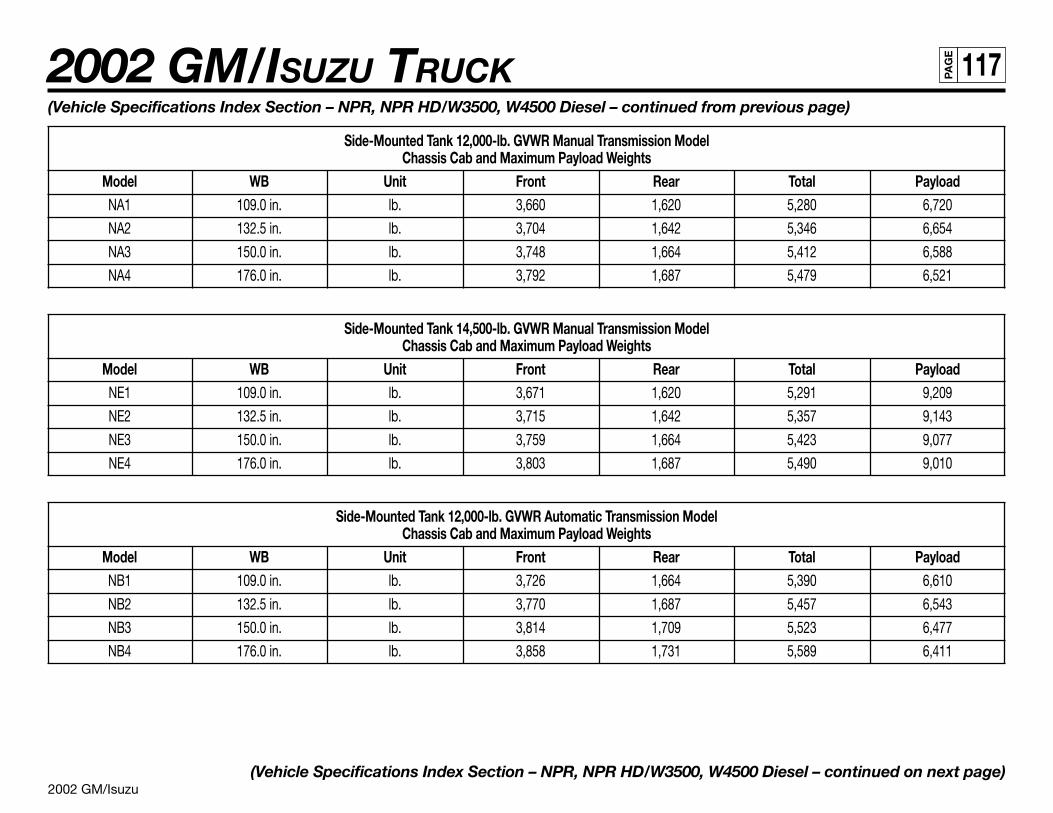
2002 GM/Isuzu
2002 GM/ISUZU TRUCK 117PA
GE
(Vehicle Specifications Index Section – NPR, NPR HD/W3500, W4500 Diesel – continued from previous page)
Side-Mounted Tank 12,000-lb. GVWR Manual Transmission ModelChassis Cab and Maximum Payload Weights
Model WB Unit Front Rear Total PayloadNA1 109.0 in. lb. 3,660 1,620 5,280 6,720
NA2 132.5 in. lb. 3,704 1,642 5,346 6,654
NA3 150.0 in. lb. 3,748 1,664 5,412 6,588
NA4 176.0 in. lb. 3,792 1,687 5,479 6,521
Side-Mounted Tank 14,500-lb. GVWR Manual Transmission ModelChassis Cab and Maximum Payload Weights
Model WB Unit Front Rear Total PayloadNE1 109.0 in. lb. 3,671 1,620 5,291 9,209
NE2 132.5 in. lb. 3,715 1,642 5,357 9,143
NE3 150.0 in. lb. 3,759 1,664 5,423 9,077
NE4 176.0 in. lb. 3,803 1,687 5,490 9,010
Side-Mounted Tank 12,000-lb. GVWR Automatic Transmission ModelChassis Cab and Maximum Payload Weights
Model WB Unit Front Rear Total PayloadNB1 109.0 in. lb. 3,726 1,664 5,390 6,610
NB2 132.5 in. lb. 3,770 1,687 5,457 6,543
NB3 150.0 in. lb. 3,814 1,709 5,523 6,477
NB4 176.0 in. lb. 3,858 1,731 5,589 6,411
(Vehicle Specifications Index Section – NPR, NPR HD/W3500, W4500 Diesel – continued on next page)
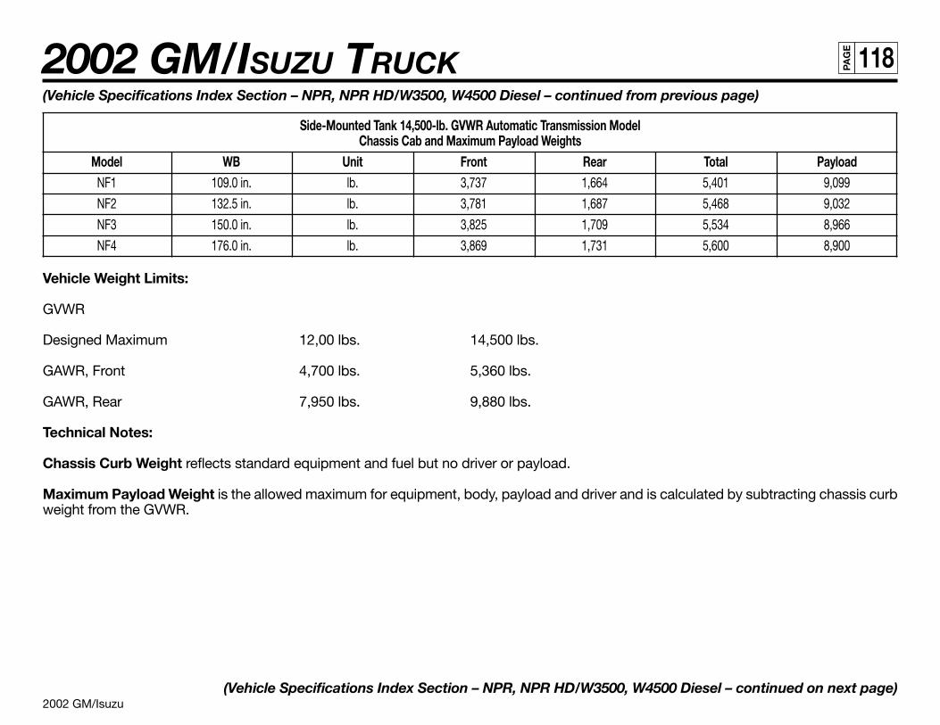
2002 GM/Isuzu
2002 GM/ISUZU TRUCK 118PA
GE
(Vehicle Specifications Index Section – NPR, NPR HD/W3500, W4500 Diesel – continued from previous page)
Side-Mounted Tank 14,500-lb. GVWR Automatic Transmission ModelChassis Cab and Maximum Payload Weights
Model WB Unit Front Rear Total PayloadNF1 109.0 in. lb. 3,737 1,664 5,401 9,099
NF2 132.5 in. lb. 3,781 1,687 5,468 9,032
NF3 150.0 in. lb. 3,825 1,709 5,534 8,966
NF4 176.0 in. lb. 3,869 1,731 5,600 8,900
Vehicle Weight Limits:
GVWR
Designed Maximum 12,00 lbs. 14,500 lbs.
GAWR, Front 4,700 lbs. 5,360 lbs.
GAWR, Rear 7,950 lbs. 9,880 lbs.
Technical Notes:
Chassis Curb Weight reflects standard equipment and fuel but no driver or payload.
Maximum Payload Weight is the allowed maximum for equipment, body, payload and driver and is calculated by subtracting chassis curbweight from the GVWR.
(Vehicle Specifications Index Section – NPR, NPR HD/W3500, W4500 Diesel – continued on next page)
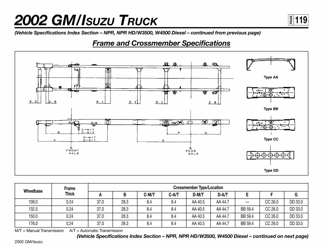
2002 GM/Isuzu
2002 GM/ISUZU TRUCK 119PA
GE
Wheelbase Frame Crossmember Type/LocationThick A B C-M/T C-A/T D-M/T D-A/T E F G
109.0 0.24 37.0 28.3 8.4 8.4 AA 40.5 AA 44.7 — CC 26.0 DD 33.0
132.5 0.24 37.0 28.3 8.4 8.4 AA 40.5 AA 44.7 BB 59.4 CC 26.0 DD 33.0
150.0 0.24 37.0 28.3 8.4 8.4 AA 40.5 AA 44.7 BB 59.4 CC 26.0 DD 33.0
176.0 0.24 37.0 28.3 8.4 8.4 AA 40.5 AA 44.7 BB 59.4 CC 26.0 DD 33.0M/T = Manual Transmission A/T = Automatic Transmission
(Vehicle Specifications Index Section – NPR, NPR HD/W3500, W4500 Diesel – continued on next page)
(Vehicle Specifications Index Section – NPR, NPR HD/W3500, W4500 Diesel – continued from previous page)
Frame and Crossmember Specifications

2002 GM/Isuzu
2002 GM/ISUZU TRUCK 120PA
GE
Wheelbase Frame FL Frame Thickness109.0 186.0 0.24
132.5 209.6 0.24
150.0 227.4 0.24
176.0 253.4 0.24
(Vehicle Specifications Index Section – NPR, NPR HD/W3500, W4500 Diesel – continued on next page)
(Vehicle Specifications Index Section – NPR, NPR HD/W3500, W4500 Diesel – continued from previous page)
Frame Chart
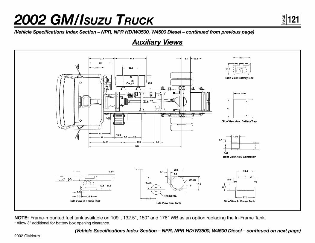
2002 GM/Isuzu
2002 GM/ISUZU TRUCK 121PA
GE
(Vehicle Specifications Index Section – NPR, NPR HD/W3500, W4500 Diesel – continued from previous page)
Auxiliary Views
NOTE: Frame-mounted fuel tank available on 109", 132.5", 150" and 176" WB as an option replacing the In-Frame Tank.* Allow 3" additional for battery box opening clearance.
(Vehicle Specifications Index Section – NPR, NPR HD/W3500, W4500 Diesel – continued on next page)
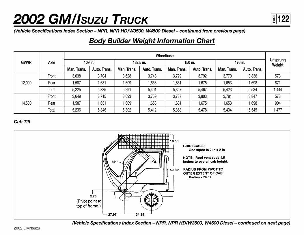
2002 GM/Isuzu
2002 GM/ISUZU TRUCK 122PA
GE
(Vehicle Specifications Index Section – NPR, NPR HD/W3500, W4500 Diesel – continued from previous page)
Body Builder Weight Information Chart
WheelbaseUnsprungGVWR Axle 109 in. 132.5 in. 150 in. 176 in. Weight
Man. Trans. Auto. Trans. Man. Trans. Auto. Trans. Man. Trans. Auto. Trans. Man. Trans. Auto. Trans.Front 3,638 3,704 3,628 3,748 3,729 3,792 3,770 3,836 573
12,000 Rear 1,587 1,631 1,609 1,653 1,631 1,675 1,653 1,698 871
Total 5,225 5,335 5,291 5,401 5,357 5,467 5,423 5,534 1,444
Front 3,649 3,715 3,693 3,759 3,737 3,803 3,781 3,847 573
14,500 Rear 1,587 1,631 1,609 1,653 1,631 1,675 1,653 1,698 904
Total 5,236 5,346 5,302 5,412 5,368 5,478 5,434 5,545 1,477
Cab Tilt
(Vehicle Specifications Index Section – NPR, NPR HD/W3500, W4500 Diesel – continued on next page)
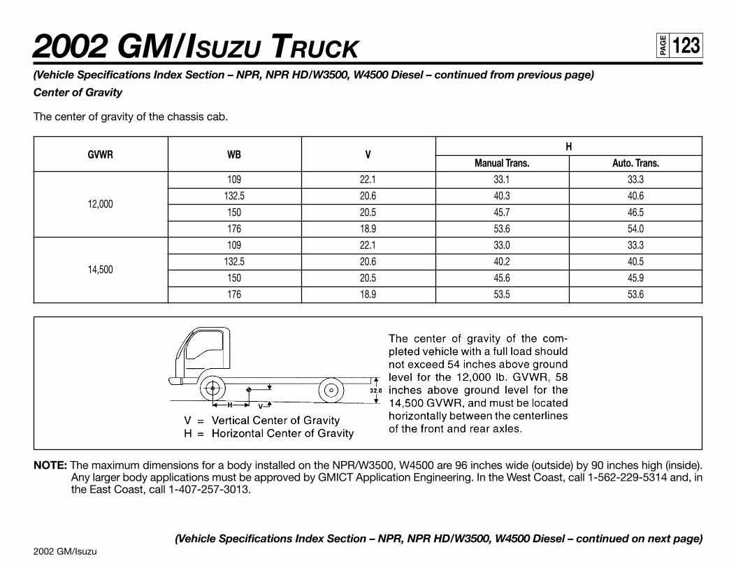
2002 GM/Isuzu
2002 GM/ISUZU TRUCK 123PA
GE
(Vehicle Specifications Index Section – NPR, NPR HD/W3500, W4500 Diesel – continued from previous page)
Center of Gravity
The center of gravity of the chassis cab.
GVWR WB VH
Manual Trans. Auto. Trans.109 22.1 33.1 33.3
12,000132.5 20.6 40.3 40.6
150 20.5 45.7 46.5
176 18.9 53.6 54.0
109 22.1 33.0 33.3
14,500132.5 20.6 40.2 40.5
150 20.5 45.6 45.9
176 18.9 53.5 53.6
NOTE: The maximum dimensions for a body installed on the NPR/W3500, W4500 are 96 inches wide (outside) by 90 inches high (inside).Any larger body applications must be approved by GMICT Application Engineering. In the West Coast, call 1-562-229-5314 and, inthe East Coast, call 1-407-257-3013.
(Vehicle Specifications Index Section – NPR, NPR HD/W3500, W4500 Diesel – continued on next page)
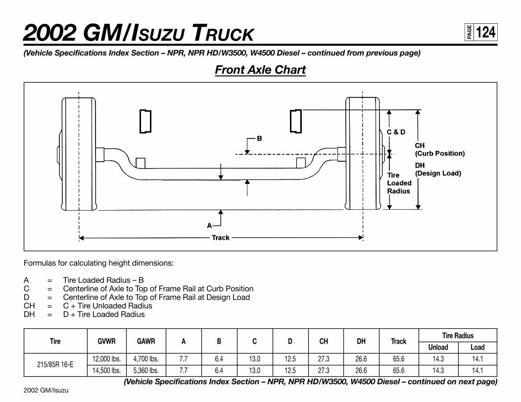
2002 GM/Isuzu
2002 GM/ISUZU TRUCK 124PA
GE
(Vehicle Specifications Index Section – NPR, NPR HD/W3500, W4500 Diesel – continued from previous page)
Front Axle Chart
Formulas for calculating height dimensions:
A = Tire Loaded Radius – BC = Centerline of Axle to Top of Frame Rail at Curb PositionD = Centerline of Axle to Top of Frame Rail at Design LoadCH = C + Tire Unloaded RadiusDH = D + Tire Loaded Radius
Tire GVWR GAWR A B C D CH DH TrackTire Radius
Unload Load
215/85R 16-E12,000 lbs. 4,700 lbs. 7.7 6.4 13.0 12.5 27.3 26.6 65.6 14.3 14.1
14,500 lbs. 5,360 lbs. 7.7 6.4 13.0 12.5 27.3 26.6 65.6 14.3 14.1(Vehicle Specifications Index Section – NPR, NPR HD/W3500, W4500 Diesel – continued on next page)
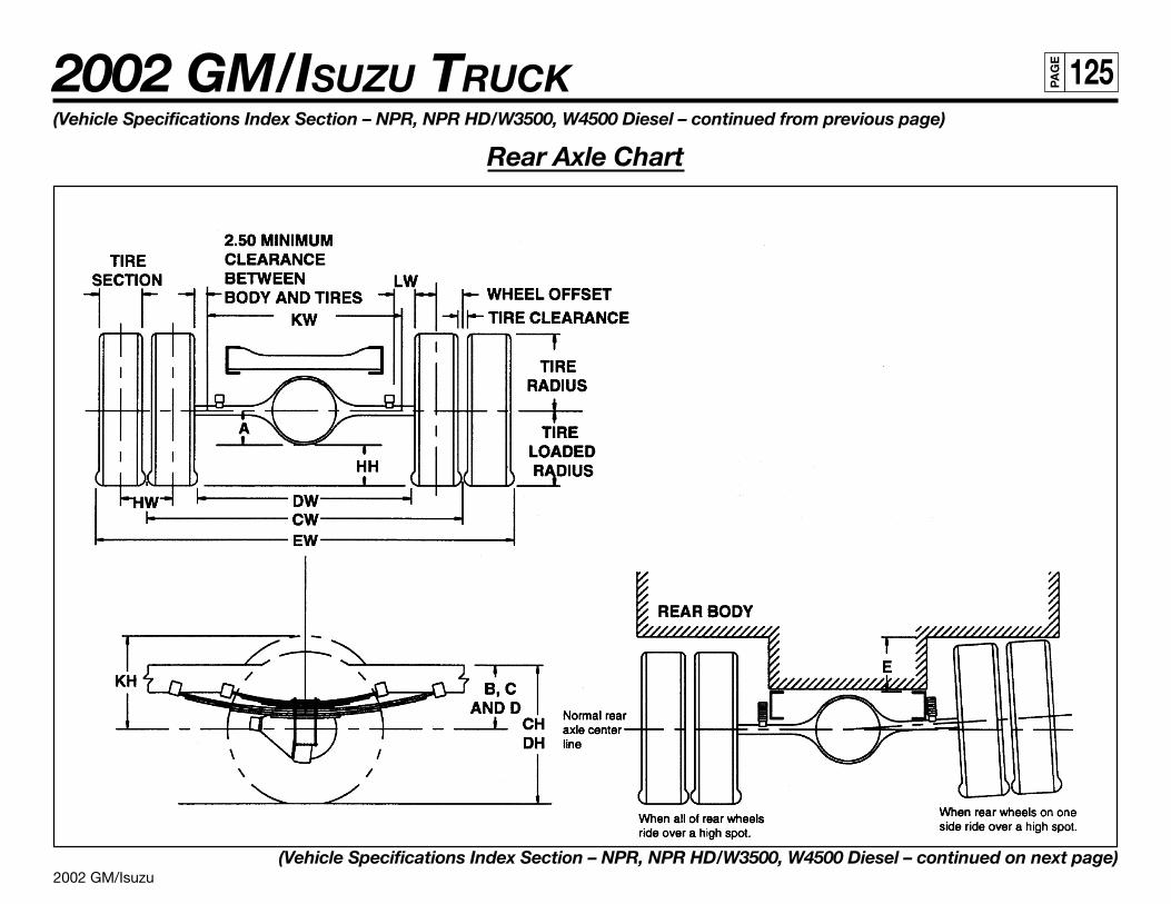
2002 GM/Isuzu
2002 GM/ISUZU TRUCK 125PA
GE
(Vehicle Specifications Index Section – NPR, NPR HD/W3500, W4500 Diesel – continued from previous page)
Rear Axle Chart
(Vehicle Specifications Index Section – NPR, NPR HD/W3500, W4500 Diesel – continued on next page)
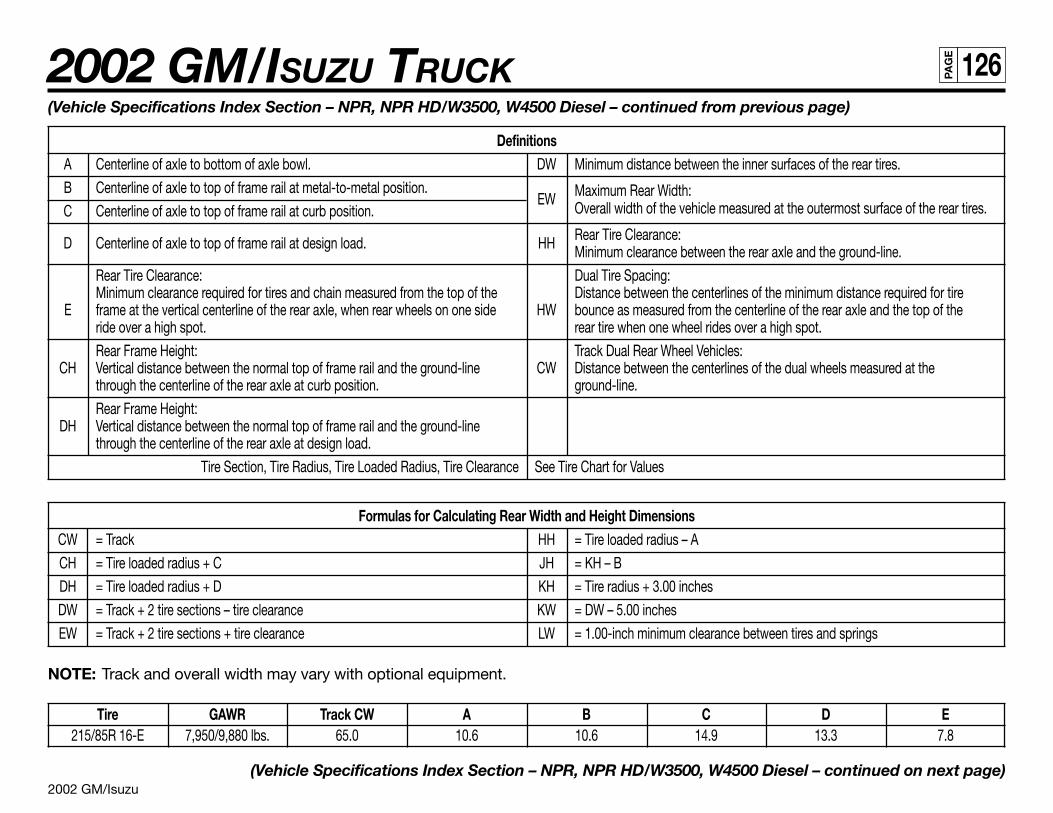
2002 GM/Isuzu
2002 GM/ISUZU TRUCK 126PA
GE
(Vehicle Specifications Index Section – NPR, NPR HD/W3500, W4500 Diesel – continued from previous page)
DefinitionsA Centerline of axle to bottom of axle bowl. DW Minimum distance between the inner surfaces of the rear tires.
B Centerline of axle to top of frame rail at metal-to-metal position.EW Maximum Rear Width:
C Centerline of axle to top of frame rail at curb position. Overall width of the vehicle measured at the outermost surface of the rear tires.
D Centerline of axle to top of frame rail at design load. HH Rear Tire Clearance:Minimum clearance between the rear axle and the ground-line.
Rear Tire Clearance: Dual Tire Spacing:Minimum clearance required for tires and chain measured from the top of the Distance between the centerlines of the minimum distance required for tire
E frame at the vertical centerline of the rear axle, when rear wheels on one side HW bounce as measured from the centerline of the rear axle and the top of theride over a high spot. rear tire when one wheel rides over a high spot.
Rear Frame Height: Track Dual Rear Wheel Vehicles:CH Vertical distance between the normal top of frame rail and the ground-line CW Distance between the centerlines of the dual wheels measured at the
through the centerline of the rear axle at curb position. ground-line.
Rear Frame Height:DH Vertical distance between the normal top of frame rail and the ground-line
through the centerline of the rear axle at design load.
Tire Section, Tire Radius, Tire Loaded Radius, Tire Clearance See Tire Chart for Values
Formulas for Calculating Rear Width and Height DimensionsCW = Track HH = Tire loaded radius – A
CH = Tire loaded radius + C JH = KH – B
DH = Tire loaded radius + D KH = Tire radius + 3.00 inches
DW = Track + 2 tire sections – tire clearance KW = DW – 5.00 inches
EW = Track + 2 tire sections + tire clearance LW = 1.00-inch minimum clearance between tires and springs
NOTE: Track and overall width may vary with optional equipment.
Tire GAWR Track CW A B C D E215/85R 16-E 7,950/9,880 lbs. 65.0 10.6 10.6 14.9 13.3 7.8
(Vehicle Specifications Index Section – NPR, NPR HD/W3500, W4500 Diesel – continued on next page)
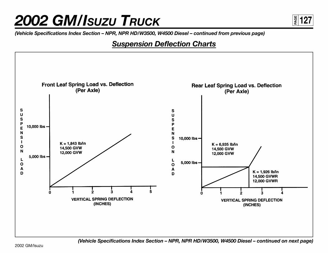
2002 GM/Isuzu
2002 GM/ISUZU TRUCK 127PA
GE
(Vehicle Specifications Index Section – NPR, NPR HD/W3500, W4500 Diesel – continued from previous page)
Suspension Deflection Charts
(Vehicle Specifications Index Section – NPR, NPR HD/W3500, W4500 Diesel – continued on next page)
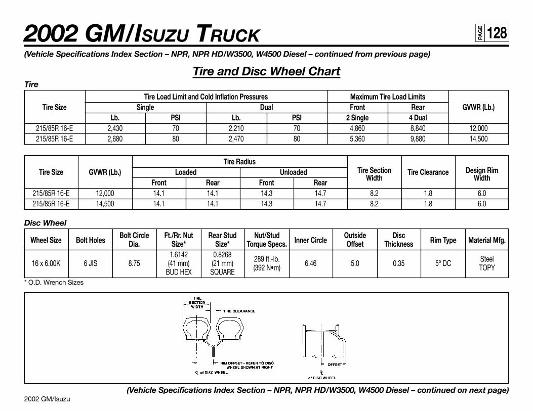
2002 GM/Isuzu
2002 GM/ISUZU TRUCK 128PA
GE
(Vehicle Specifications Index Section – NPR, NPR HD/W3500, W4500 Diesel – continued from previous page)
Tire and Disc Wheel ChartTire
Tire Load Limit and Cold Inflation Pressures Maximum Tire Load LimitsTire Size Single Dual Front Rear GVWR (Lb.)
Lb. PSI Lb. PSI 2 Single 4 Dual215/85R 16-E 2,430 70 2,210 70 4,860 8,840 12,000215/85R 16-E 2,680 80 2,470 80 5,360 9,880 14,500
Tire RadiusTire Section Design RimTire Size GVWR (Lb.) Loaded Unloaded
WidthTire Clearance
WidthFront Rear Front Rear215/85R 16-E 12,000 14.1 14.1 14.3 14.7 8.2 1.8 6.0215/85R 16-E 14,500 14.1 14.1 14.3 14.7 8.2 1.8 6.0
Disc Wheel
Wheel Size Bolt HolesBolt Circle Ft./Rr. Nut Rear Stud Nut/Stud
Inner CircleOutside Disc
Rim Type Material Mfg.Dia. Size* Size* Torque Specs. Offset Thickness1.6142 0.8268 289 ft.-lb. Steel16 x 6.00K 6 JIS 8.75 (41 mm) (21 mm) (392 N•m) 6.46 5.0 0.35 5º DC TOPYBUD HEX SQUARE
* O.D. Wrench Sizes
(Vehicle Specifications Index Section – NPR, NPR HD/W3500, W4500 Diesel – continued on next page)
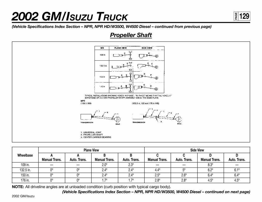
2002 GM/Isuzu
2002 GM/ISUZU TRUCK 129PA
GE
Plane View Side ViewWheelbase A A B B C C D D
Manual Trans. Auto. Trans. Manual Trans. Auto. Trans. Manual Trans. Auto. Trans. Manual Trans. Auto. Trans.109 in. — — 2.0º 2.3º — — 8.3º —
132.5 in. 0º 0º 2.4º 2.4º 4.4º 5º 6.2º 6.1º150 in. 0º 0º 2.4º 2.4º 2.5º 2.6º 6.4º 6.4º176 in. 0º 0º 1.7º 1.7º 2.8º 2.8º 4.5º 4.5º
NOTE: All driveline angles are at unloaded condition (curb position with typical cargo body).(Vehicle Specifications Index Section – NPR, NPR HD/W3500, W4500 Diesel – continued on next page)
(Vehicle Specifications Index Section – NPR, NPR HD/W3500, W4500 Diesel – continued from previous page)
Propeller Shaft
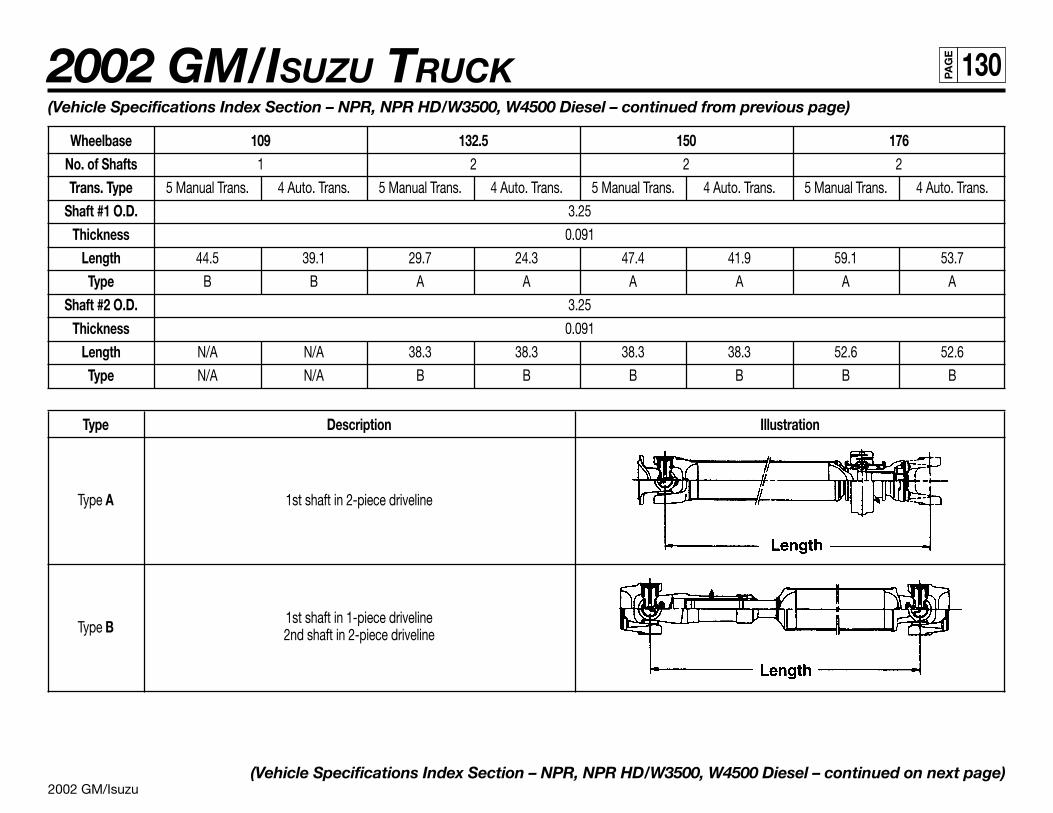
2002 GM/Isuzu
2002 GM/ISUZU TRUCK 130PA
GE
(Vehicle Specifications Index Section – NPR, NPR HD/W3500, W4500 Diesel – continued from previous page)
Wheelbase 109 132.5 150 176No. of Shafts 1 2 2 2
Trans. Type 5 Manual Trans. 4 Auto. Trans. 5 Manual Trans. 4 Auto. Trans. 5 Manual Trans. 4 Auto. Trans. 5 Manual Trans. 4 Auto. Trans.
Shaft #1 O.D. 3.25
Thickness 0.091
Length 44.5 39.1 29.7 24.3 47.4 41.9 59.1 53.7
Type B B A A A A A A
Shaft #2 O.D. 3.25
Thickness 0.091
Length N/A N/A 38.3 38.3 38.3 38.3 52.6 52.6
Type N/A N/A B B B B B B
Type Description Illustration
Type A 1st shaft in 2-piece driveline
Type B1st shaft in 1-piece driveline2nd shaft in 2-piece driveline
(Vehicle Specifications Index Section – NPR, NPR HD/W3500, W4500 Diesel – continued on next page)
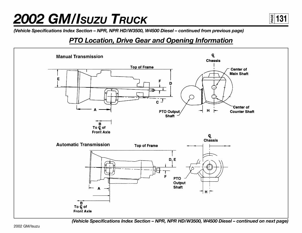
2002 GM/Isuzu
2002 GM/ISUZU TRUCK 131PA
GE
(Vehicle Specifications Index Section – NPR, NPR HD/W3500, W4500 Diesel – continued from previous page)
PTO Location, Drive Gear and Opening Information
(Vehicle Specifications Index Section – NPR, NPR HD/W3500, W4500 Diesel – continued on next page)
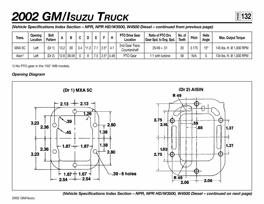
2002 GM/Isuzu
2002 GM/ISUZU TRUCK 132PA
GE
(Vehicle Specifications Index Section – NPR, NPR HD/W3500, W4500 Diesel – continued from previous page)
Trans.Opening Bolt
A B C D E F HPTO Drive Gear Ratio of PTO Drv. No. of
PitchHelix
Max. Output TorqueLocation Pattern Location Gear Spd. to Eng. Spd. Teeth Angle
MXA 5C Left (Dr 1) 13.2 39 3.4 11.2 7.1 2.5º 4.12nd Gear Trans.
25/49 = .51 20 3.175 15º 145 lbs.-ft. @ 1,000 RPMCountershaft
Aisin1) Left (Dr 2) 12.6 38.59 0 8 7.5 2.5º 4.48 PTO Gear 1:1 with turbine 58 N/A 0 134 lbs.-ft. @ 1,000 RPM
1) No PTO gear in the 150" WB models.
Opening Diagram
(Vehicle Specifications Index Section – NPR, NPR HD/W3500, W4500 Diesel – continued on next page)
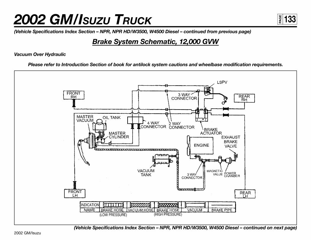
2002 GM/Isuzu
2002 GM/ISUZU TRUCK 133PA
GE
(Vehicle Specifications Index Section – NPR, NPR HD/W3500, W4500 Diesel – continued from previous page)
Brake System Schematic, 12,000 GVW
Vacuum Over Hydraulic
Please refer to Introduction Section of book for antilock system cautions and wheelbase modification requirements.
(Vehicle Specifications Index Section – NPR, NPR HD/W3500, W4500 Diesel – continued on next page)
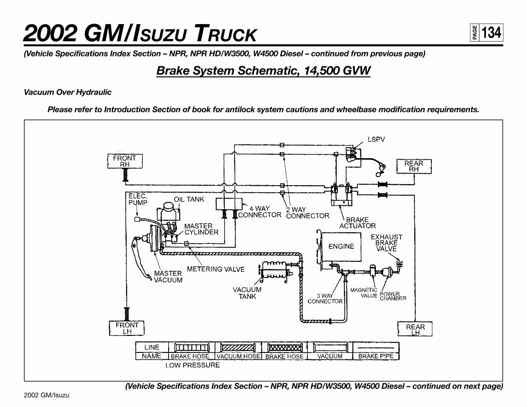
2002 GM/Isuzu
2002 GM/ISUZU TRUCK 134PA
GE
(Vehicle Specifications Index Section – NPR, NPR HD/W3500, W4500 Diesel – continued from previous page)
Brake System Schematic, 14,500 GVW
Vacuum Over Hydraulic
Please refer to Introduction Section of book for antilock system cautions and wheelbase modification requirements.
(Vehicle Specifications Index Section – NPR, NPR HD/W3500, W4500 Diesel – continued on next page)
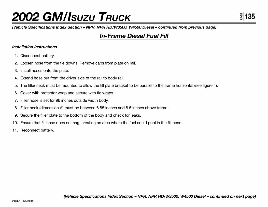
2002 GM/Isuzu
2002 GM/ISUZU TRUCK 135PA
GE
(Vehicle Specifications Index Section – NPR, NPR HD/W3500, W4500 Diesel – continued from previous page)
In-Frame Diesel Fuel Fill
Installation Instructions
1. Disconnect battery.
2. Loosen hose from the tie downs. Remove caps from plate on rail.
3. Install hoses onto the plate.
4. Extend hose out from the driver side of the rail to body rail.
5. The filler neck must be mounted to allow the fill plate bracket to be parallel to the frame horizontal (see figure 4).
6. Cover with protector wrap and secure with tie wraps.
7. Filler hose is set for 96 inches outside width body.
8. Filler neck (dimension A) must be between 6.85 inches and 8.5 inches above frame.
9. Secure the filler plate to the bottom of the body and check for leaks.
10. Ensure that fill hose does not sag, creating an area where the fuel could pool in the fill hose.
11. Reconnect battery.
(Vehicle Specifications Index Section – NPR, NPR HD/W3500, W4500 Diesel – continued on next page)
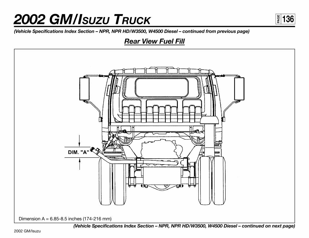
2002 GM/Isuzu
2002 GM/ISUZU TRUCK 136PA
GE
(Vehicle Specifications Index Section – NPR, NPR HD/W3500, W4500 Diesel – continued from previous page)
Rear View Fuel Fill
Dimension A = 6.85-8.5 inches (174-216 mm)
(Vehicle Specifications Index Section – NPR, NPR HD/W3500, W4500 Diesel – continued on next page)
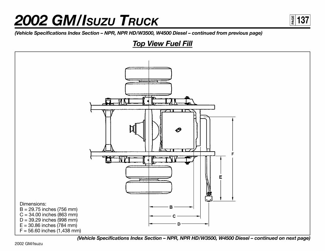
2002 GM/Isuzu
2002 GM/ISUZU TRUCK 137PA
GE
(Vehicle Specifications Index Section – NPR, NPR HD/W3500, W4500 Diesel – continued from previous page)
Top View Fuel Fill
Dimensions:B = 29.75 inches (756 mm)C = 34.00 inches (863 mm)D = 39.29 inches (998 mm)E = 30.86 inches (784 mm)F = 56.60 inches (1,438 mm)
(Vehicle Specifications Index Section – NPR, NPR HD/W3500, W4500 Diesel – continued on next page)
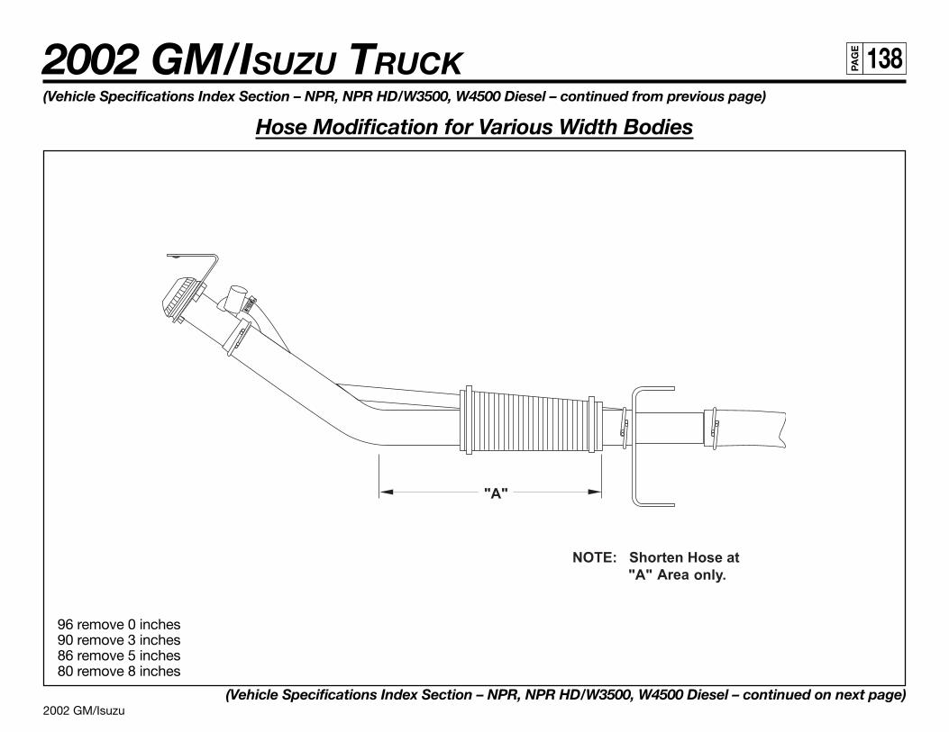
2002 GM/Isuzu
2002 GM/ISUZU TRUCK 138PA
GE
(Vehicle Specifications Index Section – NPR, NPR HD/W3500, W4500 Diesel – continued from previous page)
Hose Modification for Various Width Bodies
96 remove 0 inches90 remove 3 inches86 remove 5 inches80 remove 8 inches
(Vehicle Specifications Index Section – NPR, NPR HD/W3500, W4500 Diesel – continued on next page)
2002 GM/Isuzu
2002 GM/ISUZU TRUCK 139PA
GE
(Vehicle Specifications Index Section – NPR, NPR HD/W3500, W4500 Diesel – continued from previous page)
Through the Rail Fuel Fill Frame Hole
(Vehicle Specifications Index Section – NPR, NPR HD/W3500, W4500 Diesel – continued on next page)
2002 GM/Isuzu
2002 GM/ISUZU TRUCK 140PA
GE
(Vehicle Specifications Index Section – NPR, NPR HD/W3500, W4500 Diesel – continued from previous page)
Fuel Fill Parts Illustration
(Vehicle Specifications Index Section – NPR, NPR HD/W3500, W4500 Diesel – continued on next page)

2002 GM/Isuzu
2002 GM/ISUZU TRUCK 141PA
GE
(Vehicle Specifications Index Section – NPR, NPR HD/W3500, W4500 Diesel – continued from previous page)
Fuel Fill Parts List
Number Part Name Isuzu Part Number GM Part Number Quantity1 Breather Hose 897206-0420 N/A 1
2 Clip, Rubber Hose 894242-0340 94242034 2
3 Hose, Fuel Filler 897187-8750 97187875 1
4 Hose, Fuel Filler 897253-1400 97253140 1
5 Clip, Filler Hose 894435-8760 97724373 4
6 Screw, Filler Hose 894384-6460 N/A 3
7 Bracket, Filler Neck 897116-621Y 97116621 1
8 Cap, Filler 897118-7020 N/A 1
9 Protector 897114-0630 97114063 1
10 Clip 109707-1070 94062296 2
11 Caution Plate 894414-3530 94414353 1
2002 GM/Isuzu
2002 GM/ISUZU TRUCK 142PA
GE
NQR/W5500 DieselSpecifications
Model NQR/W5500GVWR 17,950 lbs.
WB 109 in., 132.5 in., 150 in., 176 in.
Engine lsuzu 4-cylinder, in-line 4-cycle, turbocharged, intercooled, direct injection diesel.
Model/Displacement 4HE1-TC/290 CID (4.75 liters)
HP (Gross) 175 HP @ 2,700 RPM
Torque (Gross) 347 lbs.-ft. torque @ 2,000 RPM
EquipmentDry element air cleaner with vertical intake; 2 rows 511.2 in.2 radiator; 6-blade 18.7 in. diameter fan with viscous drive.
Cold weather starting device and an oil cooler.
Clutch Single, dry plate, 12.8 in. dia. ceramic, actuated by self-adjusting hydraulic master/slave cylinder.
Transmission MBP6P 6-speed manual, all forward gears synchronized. Sixth gear is overdrive. Available Optional Transmission:Aisin 450-43 LE 4-speed overdrive automatic transmission with lock-up capability in 2nd, 3rd and 4th. PTO capability all chassis and wheelbases.
Steering Integral power steering 20.9:1 ratio. Tilt and telescoping steering column.
Front Axle Reverse Elliot “I” Beam rated at 6,830 lbs.
Suspension Semi-elliptical steel alloy leaf springs with stabilizer bar and shock absorbers.
GAWR 6,830 lbs.
Rear Axle Full-floating, single speed with hypoid gearing rated at 14,550 lbs.
Suspension Semi-elliptical steel alloy leaf springs and shock absorbers.
GAWR 12,980 lbs.
Wheels 19.5 x 6.0 6-hole disc wheels, painted white.
Tires 225/70R 19.5F (12 ply) tubeless steel-belted radials, highway tread front and rear.
Dual-circuit, power-assisted hydraulic service brakes with load-sensing proportioning valve in rear brake circuit. Disc front and self-adjustingBrakes outboard mounted drum rear. The parking brake is a mechanical, cable-actuated, internal expanding drum type,
transmission mounted. The exhaust brake is standard and is vacuum-operated. Antilock brake system.
Fuel Tank 30-gallon rectangular steel fuel tank mounted in frame rail behind rear axle. Fuel/water separator mounted on rail.
NOTE: These selected specifications are subject to change without notice.
(Vehicle Specifications Index Section – NQR/W5500 Diesel – continued on next page)
2002 GM/Isuzu
2002 GM/ISUZU TRUCK 143PA
GE
(Vehicle Specifications Index Section – NQR/W5500 Diesel – continued from previous page)
Model NQR/W5500
FrameLadder type channel section straight frame rail 33.5 in. wide through the total length of the frame.
Yield strength 44,000 psi section modulus 7.20 in.3, RBM 316,800 lbs.-ft./in. per rail.
Cab All-steel, low cab forward, BBC 68.0 in., 45º mechanical tilt with torsion assist.
EquipmentJersey knit covered high back driver’s seat with two-occupant passenger seat. Two-way roof ventilator, dual cab mounted exterior mirrors.
Tilt and telescoping steering column. Tinted glass.
Electrical 12-volt, negative ground, dual Delco maintenance free batteries, 750 CCA each, 80-amp alternator with integral regulator.
OptionsAir conditioning; AM/FM cassette stereo radio; PTO; engine block heater; engine oil pan heater; heated fuel/water separator; spare wheel;
6" stainless steel convex mirrors. Auxilliary transmission oil cooler, mandatory for 20,950 GCWR.Power windows and door locks. 33-gallon fuel tank mounted on right hand rail, in place of 30-gallon in frame tank.
NOTE: These selected specifications are subject to change without notice.
Vehicle Weights, Dimensions and Ratings
(Vehicle Specifications Index Section – NQR/W5500 Diesel – continued on next page)
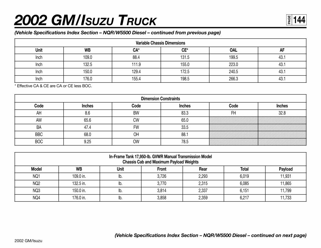
2002 GM/Isuzu
2002 GM/ISUZU TRUCK 144PA
GE
1234567890123456789012345678901212345678901234567890123456789012123456789123456789012345678901234567890121234567890123456789012345678901212345678912345678901234567890123456789012123456789012345678901234567890121234567891234567890123456789012345678901212345678901234567890123456789012123456789123456789012345678901234567890121234567890123456789012345678901212345678912345678901234567890123456789012123456789012345678901234567890121234567891234567890123456789012345678901212345678901234567890123456789012123456789123456789012345678901234567890121234567890123456789012345678901212345678912345678901234567890123456789012123456789012345678901234567890121234567891234567890123456789012345678901212345678901234567890123456789012123456789123456789012345678901234567890121234567890123456789012345678901212345678912345678901234567890123456789012123456789012345678901234567890121234567891234567890123456789012345678901212345678901234567890123456789012123456789123456789012345678901234567890121234567890123456789012345678901212345678912345678901234567890123456789012123456789012345678901234567890121234567891234567890123456789012345678901212345678901234567890123456789012123456789123456789012345678901234567890121234567890123456789012345678901212345678912345678901234567890123456789012123456789012345678901234567890121234567891234567890123456789012345678901212345678901234567890123456789012123456789123456789012345678901234567890121234567890123456789012345678901212345678912345678901234567890123456789012123456789012345678901234567890121234567891234567890123456789012345678901212345678901234567890123456789012123456789
(Vehicle Specifications Index Section – NQR/W5500 Diesel – continued from previous page)
Variable Chassis DimensionsUnit WB CA* CE* OAL AFInch 109.0 88.4 131.5 199.5 43.1
Inch 132.5 111.9 155.0 223.0 43.1
Inch 150.0 129.4 172.5 240.5 43.1
Inch 176.0 155.4 198.5 266.3 43.1* Effective CA & CE are CA or CE less BOC.
Dimension ConstraintsCode Inches Code Inches Code Inches
AH 8.6 BW 83.3 FH 32.8
AW 65.6 CW 65.0
BA 47.4 FW 33.5
BBC 68.0 OH 88.1
BOC 9.25 OW 78.5
In-Frame Tank 17,950-lb. GVWR Manual Transmission ModelChassis Cab and Maximum Payload Weights
Model WB Unit Front Rear Total PayloadNQ1 109.0 in. lb. 3,726 2,293 6,019 11,931
NQ2 132.5 in. lb. 3,770 2,315 6,085 11,865
NQ3 150.0 in. lb. 3,814 2,337 6,151 11,799
NQ4 176.0 in. lb. 3,858 2,359 6,217 11,733
(Vehicle Specifications Index Section – NQR/W5500 Diesel – continued on next page)
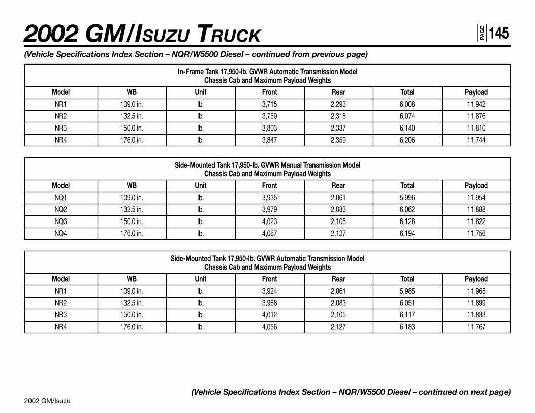
2002 GM/Isuzu
2002 GM/ISUZU TRUCK 145PA
GE
(Vehicle Specifications Index Section – NQR/W5500 Diesel – continued from previous page)
In-Frame Tank 17,950-lb. GVWR Automatic Transmission ModelChassis Cab and Maximum Payload Weights
Model WB Unit Front Rear Total PayloadNR1 109.0 in. lb. 3,715 2,293 6,008 11,942
NR2 132.5 in. lb. 3,759 2,315 6,074 11,876
NR3 150.0 in. lb. 3,803 2,337 6,140 11,810
NR4 176.0 in. lb. 3,847 2,359 6,206 11,744
Side-Mounted Tank 17,950-lb. GVWR Manual Transmission ModelChassis Cab and Maximum Payload Weights
Model WB Unit Front Rear Total PayloadNQ1 109.0 in. lb. 3,935 2,061 5,996 11,954
NQ2 132.5 in. lb. 3,979 2,083 6,062 11,888
NQ3 150.0 in. lb. 4,023 2,105 6,128 11,822
NQ4 176.0 in. lb. 4,067 2,127 6,194 11,756
Side-Mounted Tank 17,950-lb. GVWR Automatic Transmission ModelChassis Cab and Maximum Payload Weights
Model WB Unit Front Rear Total PayloadNR1 109.0 in. lb. 3,924 2,061 5,985 11,965
NR2 132.5 in. lb. 3,968 2,083 6,051 11,899
NR3 150.0 in. lb. 4,012 2,105 6,117 11,833
NR4 176.0 in. lb. 4,056 2,127 6,183 11,767
(Vehicle Specifications Index Section – NQR/W5500 Diesel – continued on next page)
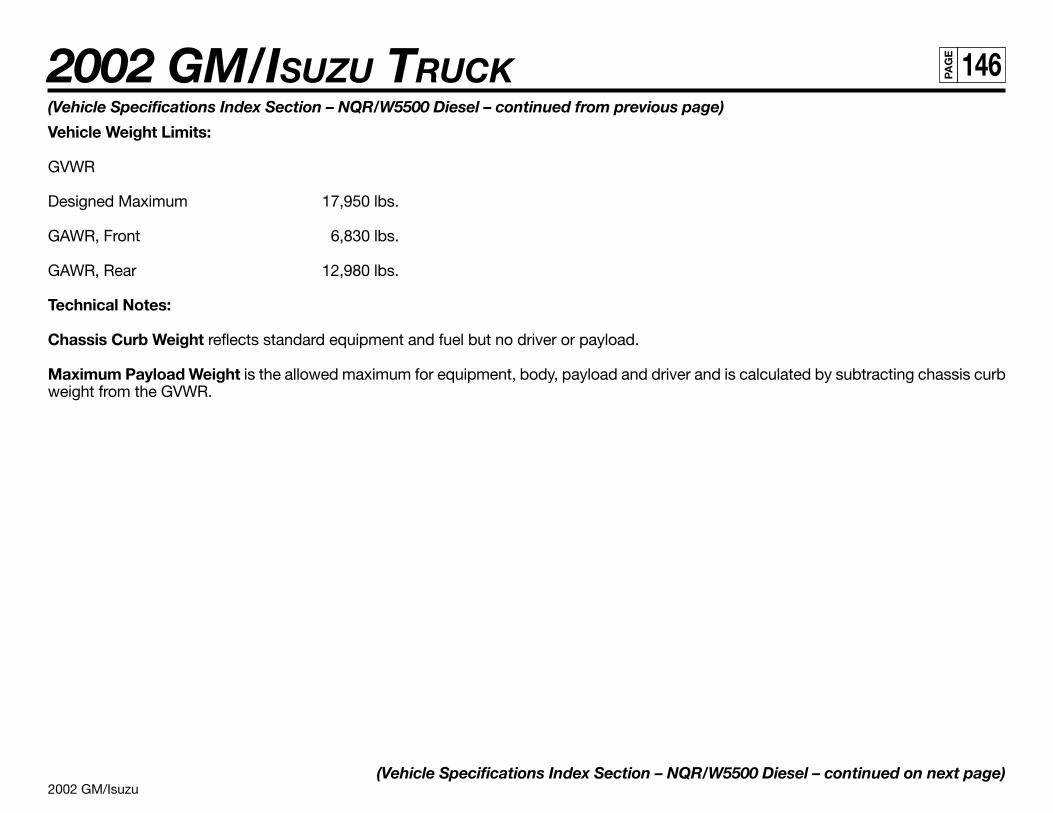
2002 GM/Isuzu
2002 GM/ISUZU TRUCK 146PA
GE
(Vehicle Specifications Index Section – NQR/W5500 Diesel – continued from previous page)
Vehicle Weight Limits:
GVWR
Designed Maximum 17,950 lbs.
GAWR, Front 6,830 lbs.
GAWR, Rear 12,980 lbs.
Technical Notes:
Chassis Curb Weight reflects standard equipment and fuel but no driver or payload.
Maximum Payload Weight is the allowed maximum for equipment, body, payload and driver and is calculated by subtracting chassis curbweight from the GVWR.
(Vehicle Specifications Index Section – NQR/W5500 Diesel – continued on next page)
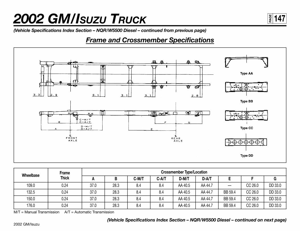
2002 GM/Isuzu
2002 GM/ISUZU TRUCK 147PA
GE
(Vehicle Specifications Index Section – NQR/W5500 Diesel – continued from previous page)
Frame and Crossmember Specifications
Wheelbase Frame Crossmember Type/LocationThick A B C-M/T C-A/T D-M/T D-A/T E F G
109.0 0.24 37.0 28.3 8.4 8.4 AA 40.5 AA 44.7 — CC 26.0 DD 33.0
132.5 0.24 37.0 28.3 8.4 8.4 AA 40.5 AA 44.7 BB 59.4 CC 26.0 DD 33.0
150.0 0.24 37.0 28.3 8.4 8.4 AA 40.5 AA 44.7 BB 59.4 CC 26.0 DD 33.0
176.0 0.24 37.0 28.3 8.4 8.4 AA 40.5 AA 44.7 BB 59.4 CC 26.0 DD 33.0M/T = Manual Transmission A/T = Automatic Transmission
(Vehicle Specifications Index Section – NQR/W5500 Diesel – continued on next page)
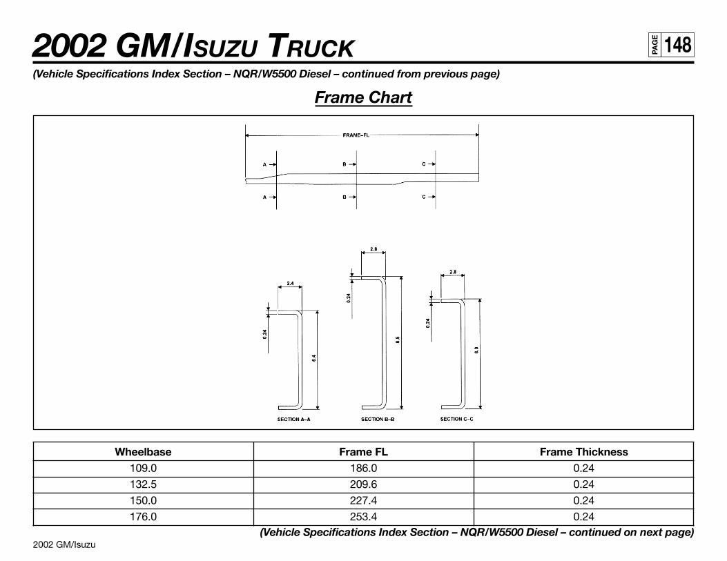
2002 GM/Isuzu
2002 GM/ISUZU TRUCK 148PA
GE
(Vehicle Specifications Index Section – NQR/W5500 Diesel – continued from previous page)
Frame Chart
Wheelbase Frame FL Frame Thickness109.0 186.0 0.24
132.5 209.6 0.24
150.0 227.4 0.24
176.0 253.4 0.24(Vehicle Specifications Index Section – NQR/W5500 Diesel – continued on next page)
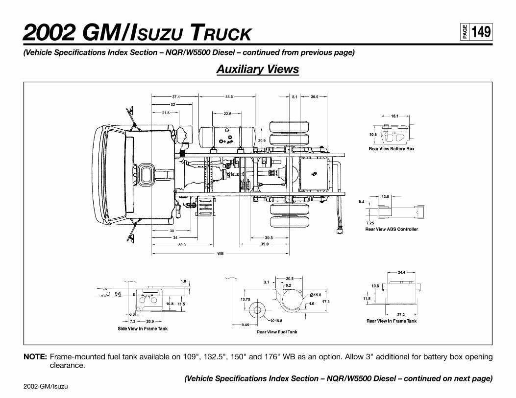
2002 GM/Isuzu
2002 GM/ISUZU TRUCK 149PA
GE
(Vehicle Specifications Index Section – NQR/W5500 Diesel – continued from previous page)
Auxiliary Views
NOTE: Frame-mounted fuel tank available on 109", 132.5", 150" and 176" WB as an option. Allow 3" additional for battery box openingclearance.
(Vehicle Specifications Index Section – NQR/W5500 Diesel – continued on next page)
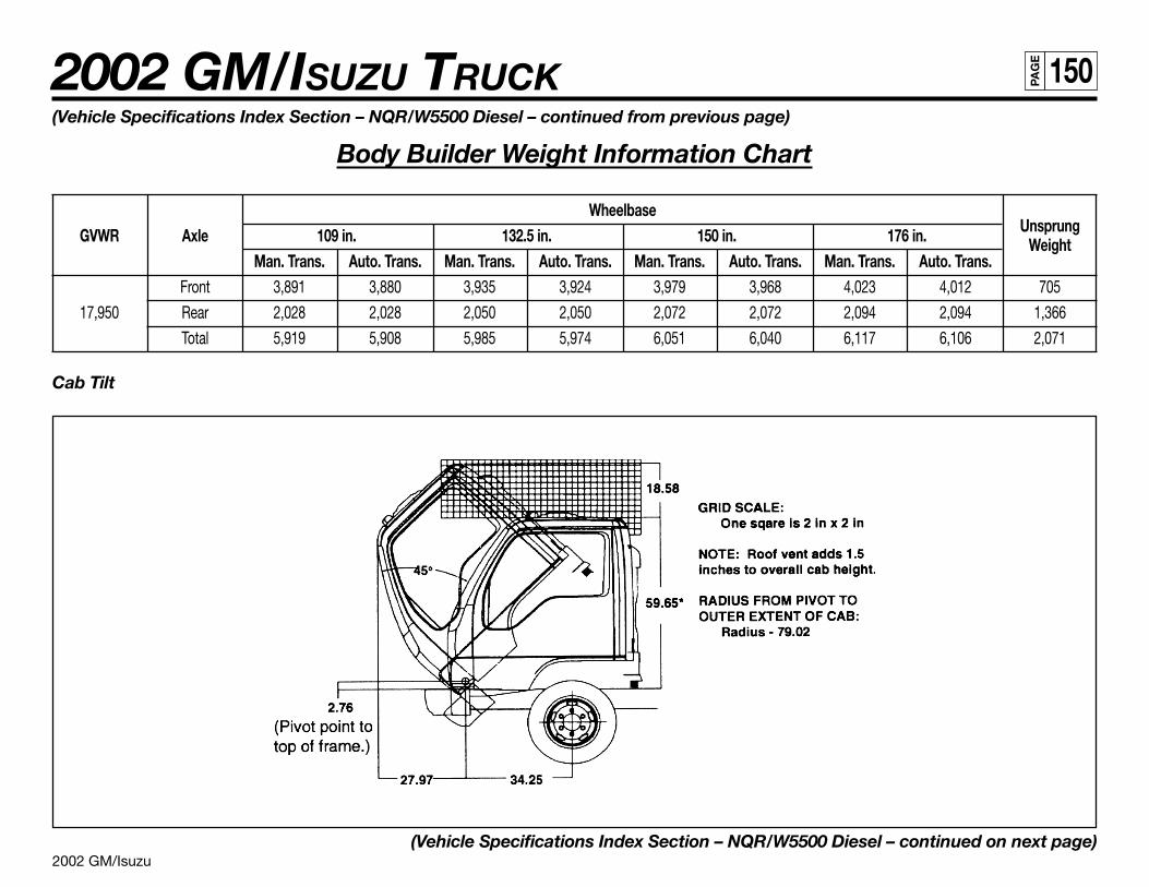
2002 GM/Isuzu
2002 GM/ISUZU TRUCK 150PA
GE
(Vehicle Specifications Index Section – NQR/W5500 Diesel – continued from previous page)
Body Builder Weight Information Chart
WheelbaseUnsprungGVWR Axle 109 in. 132.5 in. 150 in. 176 in. Weight
Man. Trans. Auto. Trans. Man. Trans. Auto. Trans. Man. Trans. Auto. Trans. Man. Trans. Auto. Trans.Front 3,891 3,880 3,935 3,924 3,979 3,968 4,023 4,012 705
17,950 Rear 2,028 2,028 2,050 2,050 2,072 2,072 2,094 2,094 1,366
Total 5,919 5,908 5,985 5,974 6,051 6,040 6,117 6,106 2,071
Cab Tilt
(Vehicle Specifications Index Section – NQR/W5500 Diesel – continued on next page)
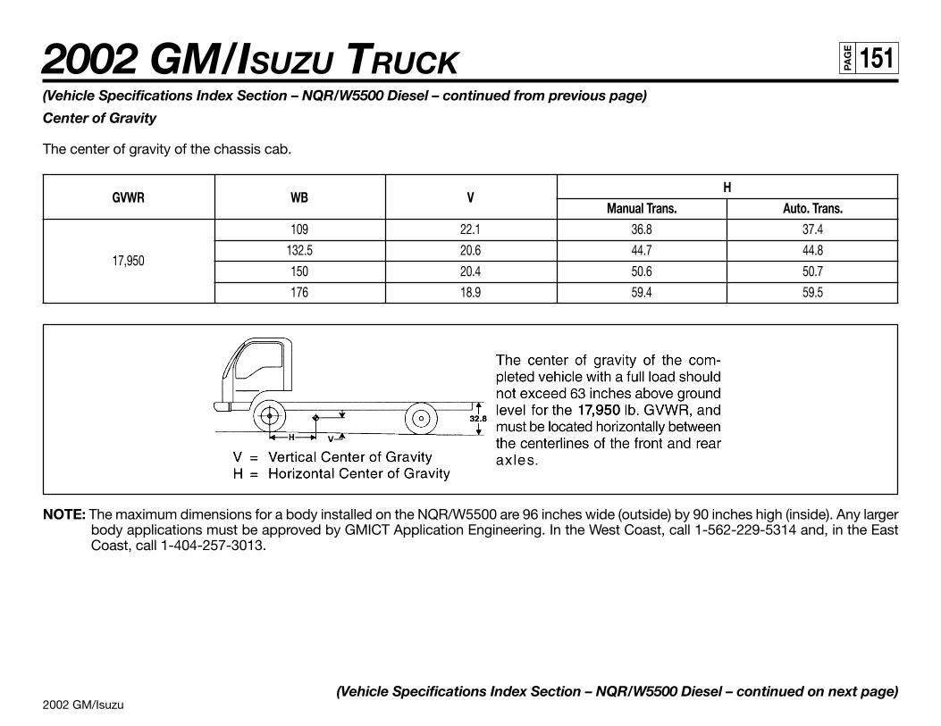
2002 GM/Isuzu
2002 GM/ISUZU TRUCK 151PA
GE
(Vehicle Specifications Index Section – NQR/W5500 Diesel – continued from previous page)
Center of Gravity
The center of gravity of the chassis cab.
GVWR WB VH
Manual Trans. Auto. Trans.109 22.1 36.8 37.4
17,950132.5 20.6 44.7 44.8
150 20.4 50.6 50.7
176 18.9 59.4 59.5
NOTE: The maximum dimensions for a body installed on the NQR/W5500 are 96 inches wide (outside) by 90 inches high (inside). Any largerbody applications must be approved by GMICT Application Engineering. In the West Coast, call 1-562-229-5314 and, in the EastCoast, call 1-404-257-3013.
(Vehicle Specifications Index Section – NQR/W5500 Diesel – continued on next page)
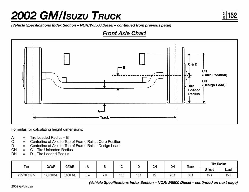
2002 GM/Isuzu
2002 GM/ISUZU TRUCK 152PA
GE
(Vehicle Specifications Index Section – NQR/W5500 Diesel – continued from previous page)
Front Axle Chart
Formulas for calculating height dimensions:
A = Tire Loaded Radius – BC = Centerline of Axle to Top of Frame Rail at Curb PositionD = Centerline of Axle to Top of Frame Rail at Design LoadCH = C + Tire Unloaded RadiusDH = D + Tire Loaded Radius
Tire GVWR GAWR A B C D CH DH TrackTire Radius
Unload Load225/70R 19.5 17,950 lbs. 6,830 lbs. 8.4 7.0 13.6 13.1 29 28.1 66.1 15.4 15.0
(Vehicle Specifications Index Section – NQR/W5500 Diesel – continued on next page)

2002 GM/Isuzu
2002 GM/ISUZU TRUCK 153PA
GE
(Vehicle Specifications Index Section – NQR/W5500 Diesel – continued from previous page)
Rear Axle Chart
(Vehicle Specifications Index Section – NQR/W5500 Diesel – continued on next page)
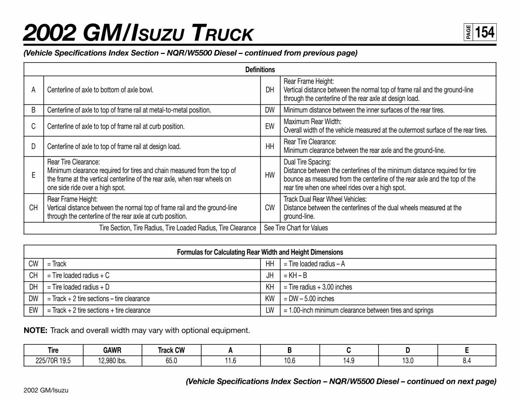
2002 GM/Isuzu
2002 GM/ISUZU TRUCK 154PA
GE
(Vehicle Specifications Index Section – NQR/W5500 Diesel – continued from previous page)
DefinitionsRear Frame Height:
A Centerline of axle to bottom of axle bowl. DH Vertical distance between the normal top of frame rail and the ground-linethrough the centerline of the rear axle at design load.
B Centerline of axle to top of frame rail at metal-to-metal position. DW Minimum distance between the inner surfaces of the rear tires.
C Centerline of axle to top of frame rail at curb position. EWMaximum Rear Width:Overall width of the vehicle measured at the outermost surface of the rear tires.
D Centerline of axle to top of frame rail at design load. HHRear Tire Clearance:Minimum clearance between the rear axle and the ground-line.
Rear Tire Clearance: Dual Tire Spacing:
EMinimum clearance required for tires and chain measured from the top of
HWDistance between the centerlines of the minimum distance required for tire
the frame at the vertical centerline of the rear axle, when rear wheels on bounce as measured from the centerline of the rear axle and the top of theone side ride over a high spot. rear tire when one wheel rides over a high spot.
Rear Frame Height: Track Dual Rear Wheel Vehicles:CH Vertical distance between the normal top of frame rail and the ground-line CW Distance between the centerlines of the dual wheels measured at the
through the centerline of the rear axle at curb position. ground-line.
Tire Section, Tire Radius, Tire Loaded Radius, Tire Clearance See Tire Chart for Values
Formulas for Calculating Rear Width and Height DimensionsCW = Track HH = Tire loaded radius – A
CH = Tire loaded radius + C JH = KH – B
DH = Tire loaded radius + D KH = Tire radius + 3.00 inches
DW = Track + 2 tire sections – tire clearance KW = DW – 5.00 inches
EW = Track + 2 tire sections + tire clearance LW = 1.00-inch minimum clearance between tires and springs
NOTE: Track and overall width may vary with optional equipment.
Tire GAWR Track CW A B C D E225/70R 19.5 12,980 lbs. 65.0 11.6 10.6 14.9 13.0 8.4
(Vehicle Specifications Index Section – NQR/W5500 Diesel – continued on next page)
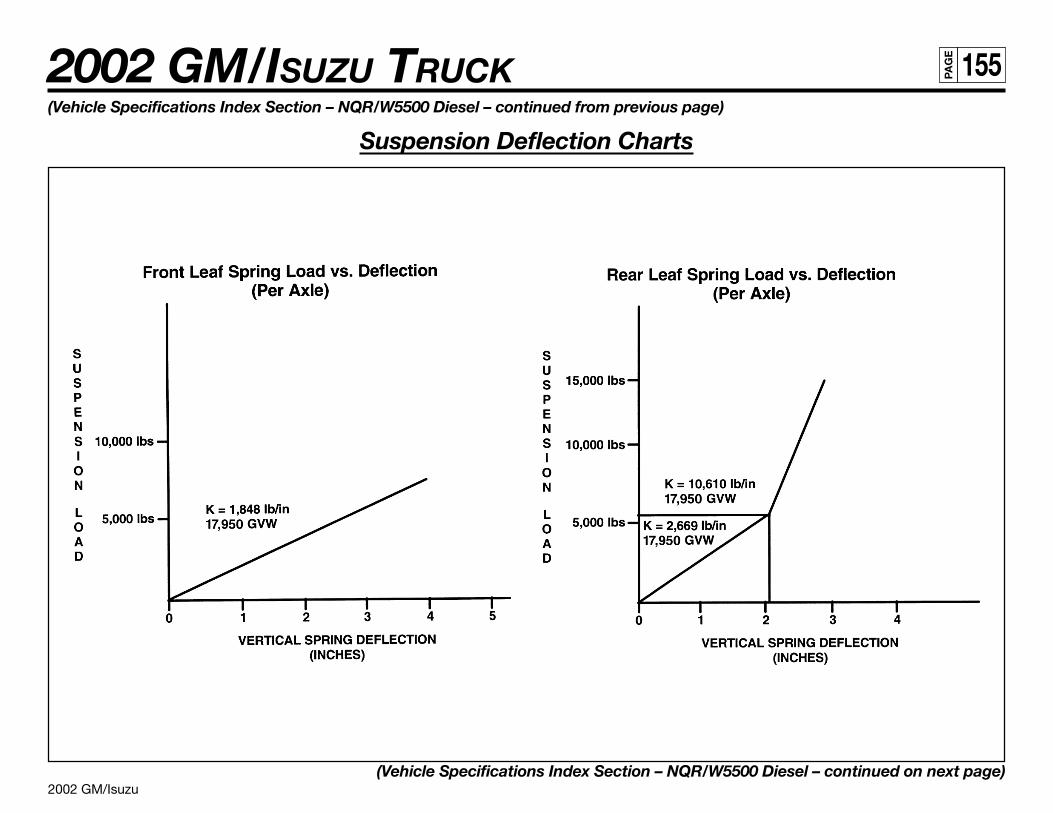
2002 GM/Isuzu
2002 GM/ISUZU TRUCK 155PA
GE
(Vehicle Specifications Index Section – NQR/W5500 Diesel – continued from previous page)
Suspension Deflection Charts
(Vehicle Specifications Index Section – NQR/W5500 Diesel – continued on next page)
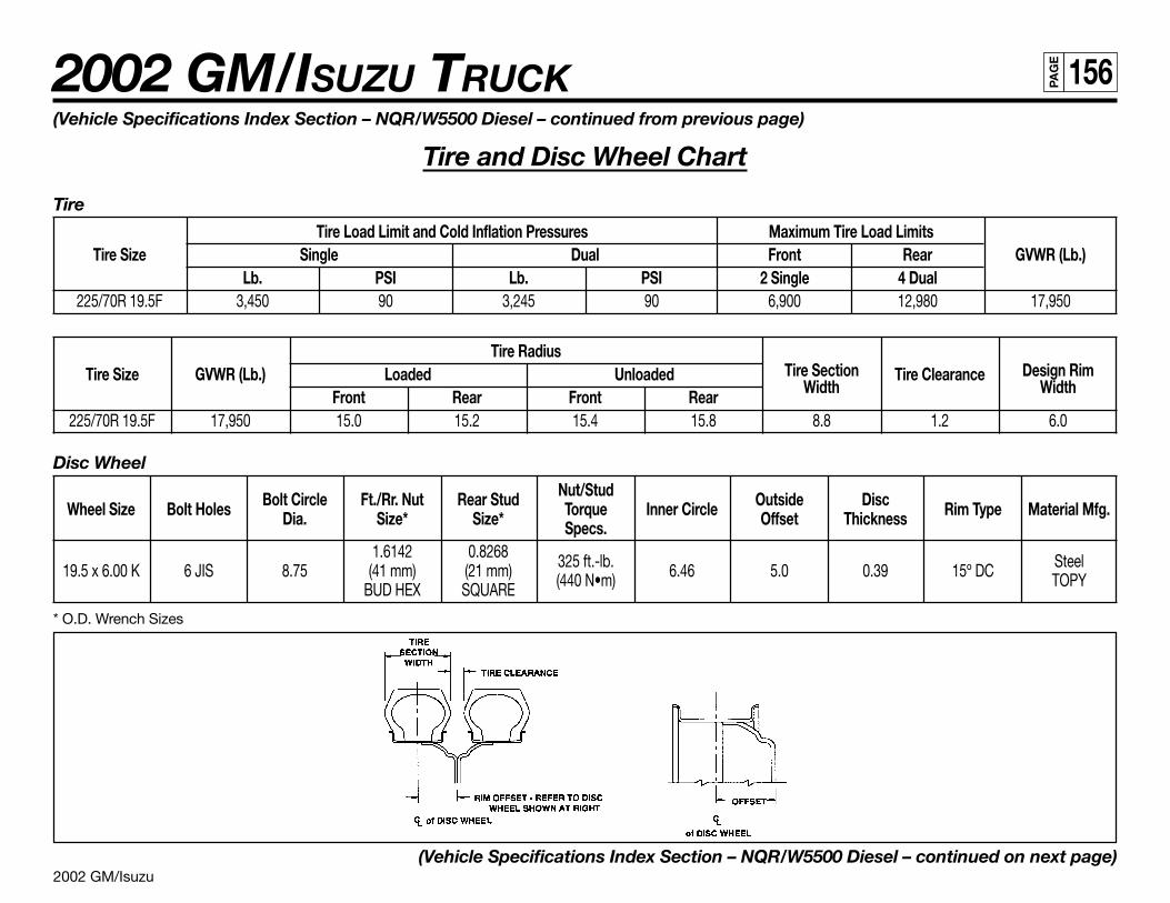
2002 GM/Isuzu
2002 GM/ISUZU TRUCK 156PA
GE
(Vehicle Specifications Index Section – NQR/W5500 Diesel – continued from previous page)
Tire and Disc Wheel Chart
Tire
Tire Load Limit and Cold Inflation Pressures Maximum Tire Load LimitsTire Size Single Dual Front Rear GVWR (Lb.)
Lb. PSI Lb. PSI 2 Single 4 Dual225/70R 19.5F 3,450 90 3,245 90 6,900 12,980 17,950
Tire RadiusTire Section Design RimTire Size GVWR (Lb.) Loaded Unloaded
WidthTire Clearance
WidthFront Rear Front Rear225/70R 19.5F 17,950 15.0 15.2 15.4 15.8 8.8 1.2 6.0
Disc Wheel
Bolt Circle Ft./Rr. Nut Rear Stud Nut/Stud Outside DiscWheel Size Bolt Holes Dia. Size* Size* Torque Inner Circle Offset Thickness Rim Type Material Mfg.Specs.
1.6142 0.8268 325 ft.-lb. Steel19.5 x 6.00 K 6 JIS 8.75 (41 mm) (21 mm) (440 N•m) 6.46 5.0 0.39 15º DC TOPYBUD HEX SQUARE
* O.D. Wrench Sizes
(Vehicle Specifications Index Section – NQR/W5500 Diesel – continued on next page)
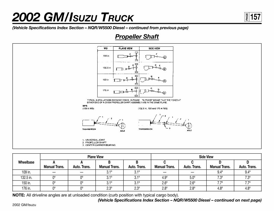
2002 GM/Isuzu
2002 GM/ISUZU TRUCK 157PA
GE
(Vehicle Specifications Index Section – NQR/W5500 Diesel – continued from previous page)
Propeller Shaft
Plane View Side ViewWheelbase A A B B C C D D
Manual Trans. Auto. Trans. Manual Trans. Auto. Trans. Manual Trans. Auto. Trans. Manual Trans. Auto. Trans.109 in. — — 3.1º 3.1º — — 9.4º 9.4º
132.5 in. 0º 0º 3.1º 3.1º 4.9º 5.0º 7.3º 7.3º150 in. 0º 0º 3.1º 3.1º 2.6º 2.6º 7.7º 7.7º176 in. 0º 0º 2.3º 2.3º 2.8º 2.8º 4.8º 4.8º
NOTE: All driveline angles are at unloaded condition (curb position with typical cargo body).(Vehicle Specifications Index Section – NQR/W5500 Diesel – continued on next page)
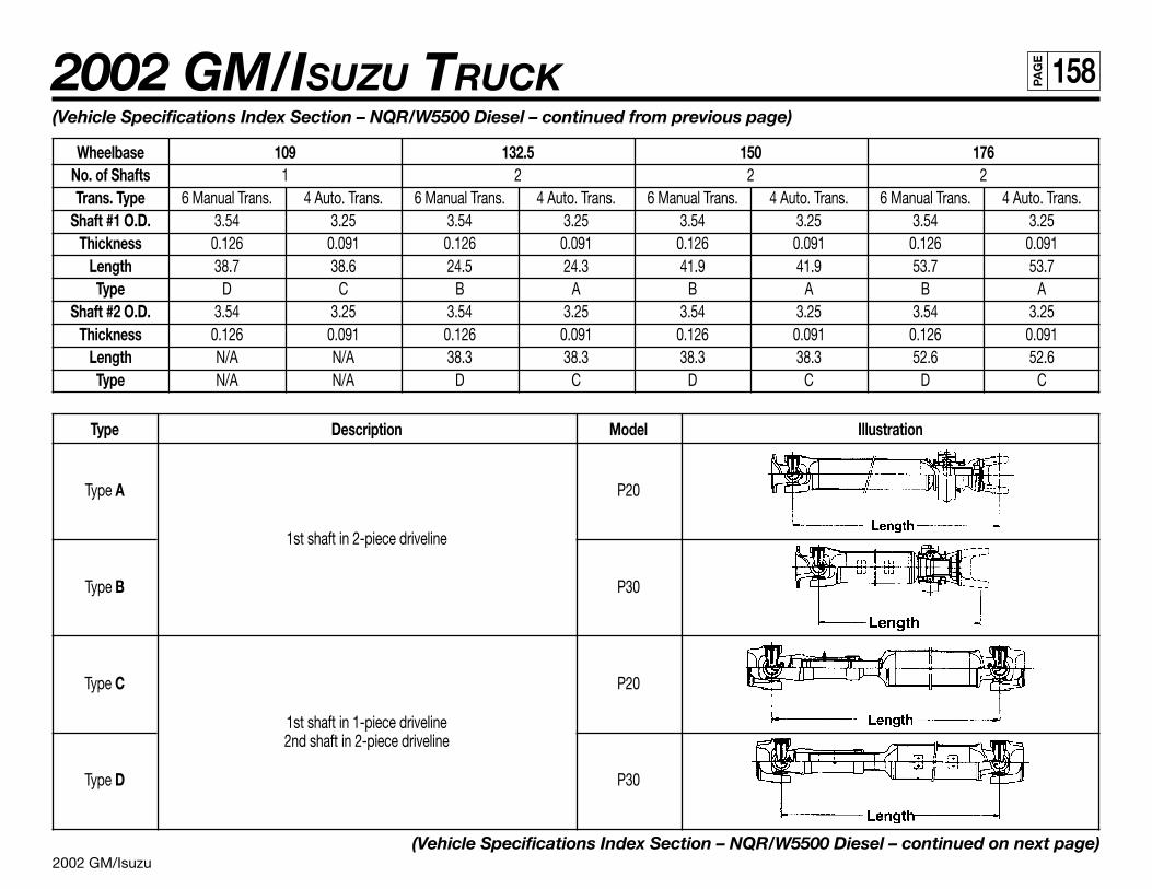
2002 GM/Isuzu
2002 GM/ISUZU TRUCK 158PA
GE
(Vehicle Specifications Index Section – NQR/W5500 Diesel – continued from previous page)
Wheelbase 109 132.5 150 176No. of Shafts 1 2 2 2Trans. Type 6 Manual Trans. 4 Auto. Trans. 6 Manual Trans. 4 Auto. Trans. 6 Manual Trans. 4 Auto. Trans. 6 Manual Trans. 4 Auto. Trans.
Shaft #1 O.D. 3.54 3.25 3.54 3.25 3.54 3.25 3.54 3.25Thickness 0.126 0.091 0.126 0.091 0.126 0.091 0.126 0.091
Length 38.7 38.6 24.5 24.3 41.9 41.9 53.7 53.7Type D C B A B A B A
Shaft #2 O.D. 3.54 3.25 3.54 3.25 3.54 3.25 3.54 3.25Thickness 0.126 0.091 0.126 0.091 0.126 0.091 0.126 0.091
Length N/A N/A 38.3 38.3 38.3 38.3 52.6 52.6Type N/A N/A D C D C D C
Type Description Model Illustration
Type A P20
1st shaft in 2-piece driveline
Type B P30
Type C P20
1st shaft in 1-piece driveline2nd shaft in 2-piece driveline
Type D P30
(Vehicle Specifications Index Section – NQR/W5500 Diesel – continued on next page)
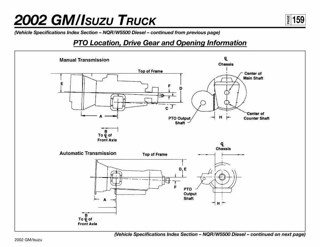
2002 GM/Isuzu
2002 GM/ISUZU TRUCK 159PA
GE
(Vehicle Specifications Index Section – NQR/W5500 Diesel – continued from previous page)
PTO Location, Drive Gear and Opening Information
(Vehicle Specifications Index Section – NQR/W5500 Diesel – continued on next page)
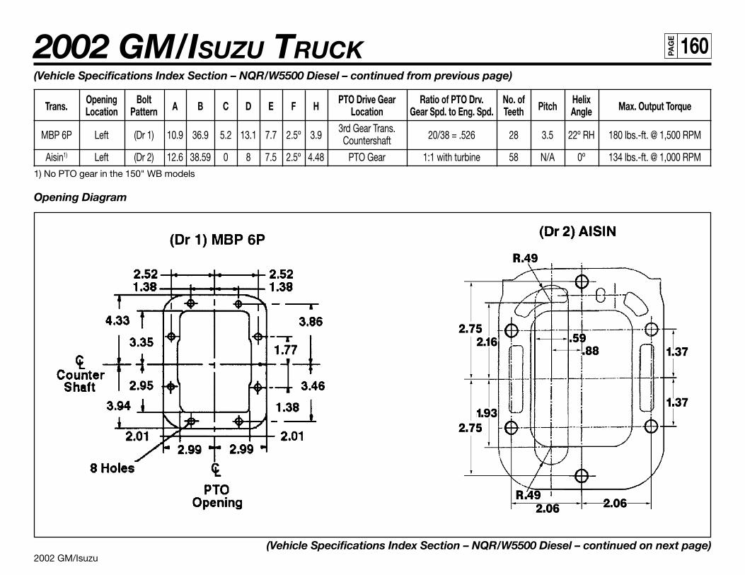
2002 GM/Isuzu
2002 GM/ISUZU TRUCK 160PA
GE
(Vehicle Specifications Index Section – NQR/W5500 Diesel – continued from previous page)
Trans.Opening Bolt
A B C D E F HPTO Drive Gear Ratio of PTO Drv. No. of
PitchHelix
Max. Output TorqueLocation Pattern Location Gear Spd. to Eng. Spd. Teeth Angle
MBP 6P Left (Dr 1) 10.9 36.9 5.2 13.1 7.7 2.5º 3.93rd Gear Trans.
20/38 = .526 28 3.5 22º RH 180 lbs.-ft. @ 1,500 RPMCountershaft
Aisin1) Left (Dr 2) 12.6 38.59 0 8 7.5 2.5º 4.48 PTO Gear 1:1 with turbine 58 N/A 0º 134 lbs.-ft. @ 1,000 RPM1) No PTO gear in the 150" WB models
Opening Diagram
(Vehicle Specifications Index Section – NQR/W5500 Diesel – continued on next page)
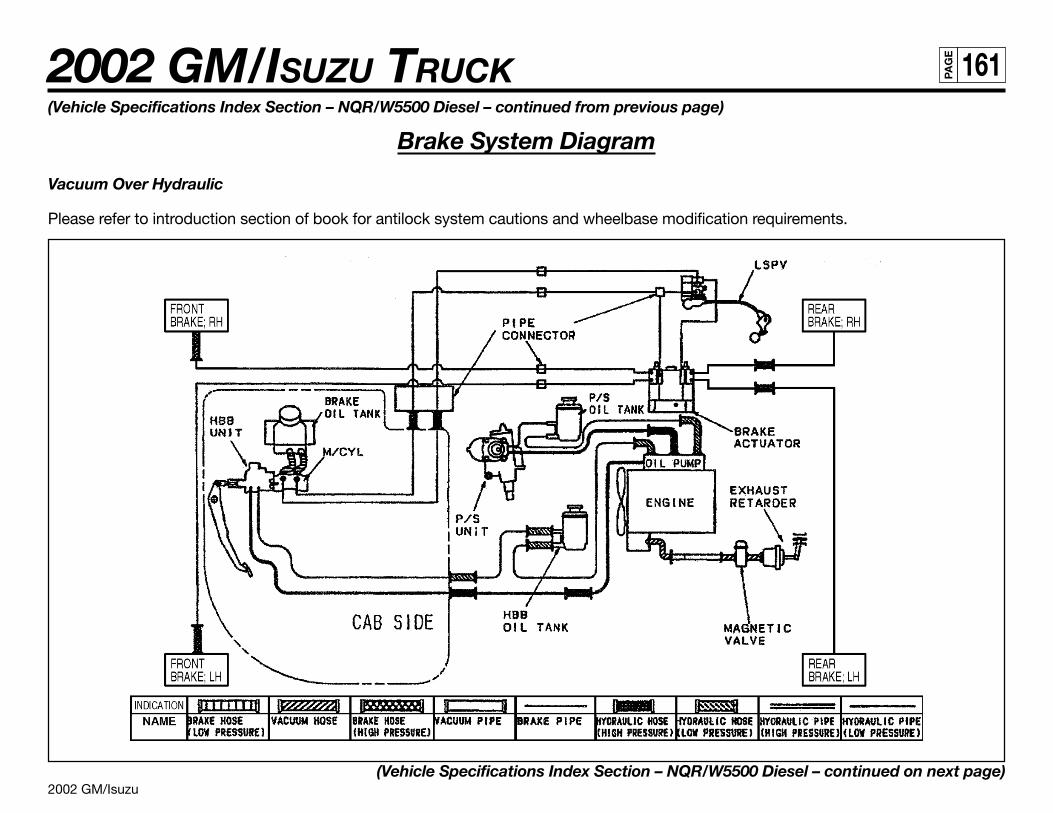
2002 GM/Isuzu
2002 GM/ISUZU TRUCK 161PA
GE
(Vehicle Specifications Index Section – NQR/W5500 Diesel – continued from previous page)
Brake System Diagram
Vacuum Over Hydraulic
Please refer to introduction section of book for antilock system cautions and wheelbase modification requirements.
(Vehicle Specifications Index Section – NQR/W5500 Diesel – continued on next page)
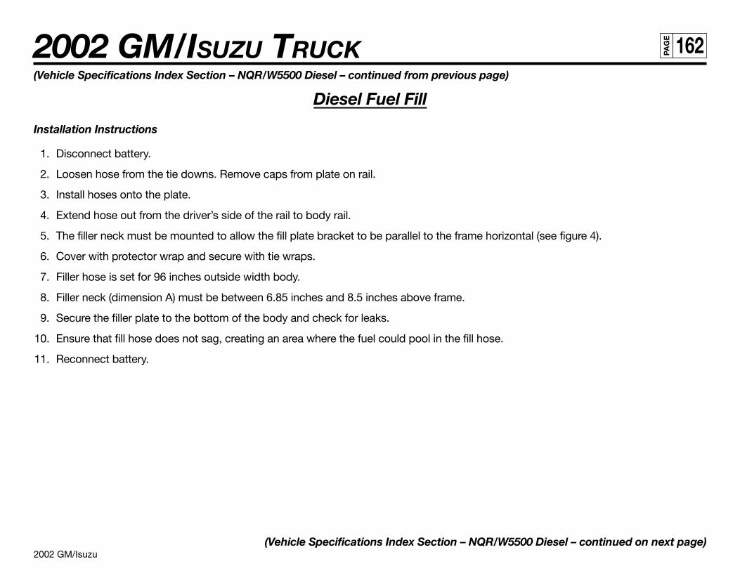
2002 GM/Isuzu
2002 GM/ISUZU TRUCK 162PA
GE
(Vehicle Specifications Index Section – NQR/W5500 Diesel – continued from previous page)
Diesel Fuel Fill
Installation Instructions
1. Disconnect battery.
2. Loosen hose from the tie downs. Remove caps from plate on rail.
3. Install hoses onto the plate.
4. Extend hose out from the driver’s side of the rail to body rail.
5. The filler neck must be mounted to allow the fill plate bracket to be parallel to the frame horizontal (see figure 4).
6. Cover with protector wrap and secure with tie wraps.
7. Filler hose is set for 96 inches outside width body.
8. Filler neck (dimension A) must be between 6.85 inches and 8.5 inches above frame.
9. Secure the filler plate to the bottom of the body and check for leaks.
10. Ensure that fill hose does not sag, creating an area where the fuel could pool in the fill hose.
11. Reconnect battery.
(Vehicle Specifications Index Section – NQR/W5500 Diesel – continued on next page)
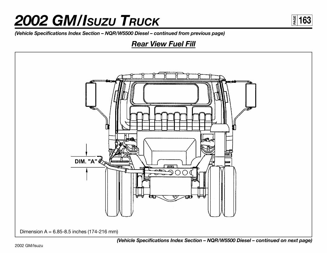
2002 GM/Isuzu
2002 GM/ISUZU TRUCK 163PA
GE
(Vehicle Specifications Index Section – NQR/W5500 Diesel – continued from previous page)
Rear View Fuel Fill
Dimension A = 6.85-8.5 inches (174-216 mm)
(Vehicle Specifications Index Section – NQR/W5500 Diesel – continued on next page)
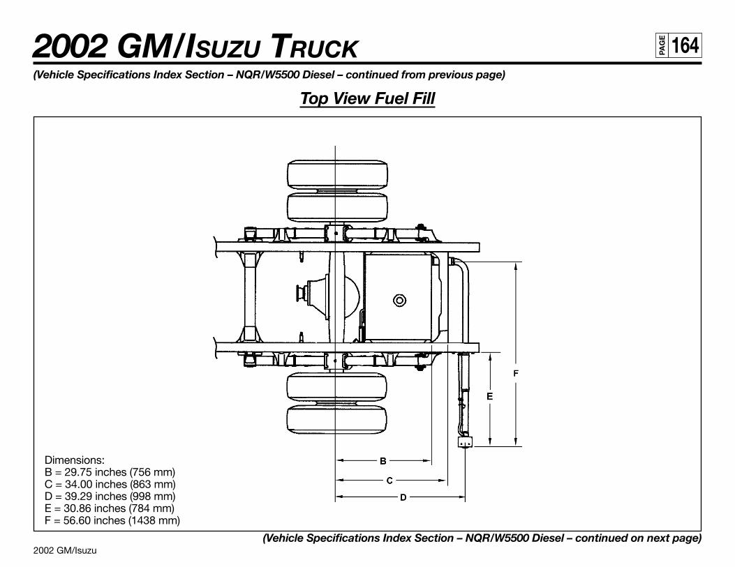
2002 GM/Isuzu
2002 GM/ISUZU TRUCK 164PA
GE
(Vehicle Specifications Index Section – NQR/W5500 Diesel – continued from previous page)
Top View Fuel Fill
Dimensions:B = 29.75 inches (756 mm)C = 34.00 inches (863 mm)D = 39.29 inches (998 mm)E = 30.86 inches (784 mm)F = 56.60 inches (1438 mm)
(Vehicle Specifications Index Section – NQR/W5500 Diesel – continued on next page)
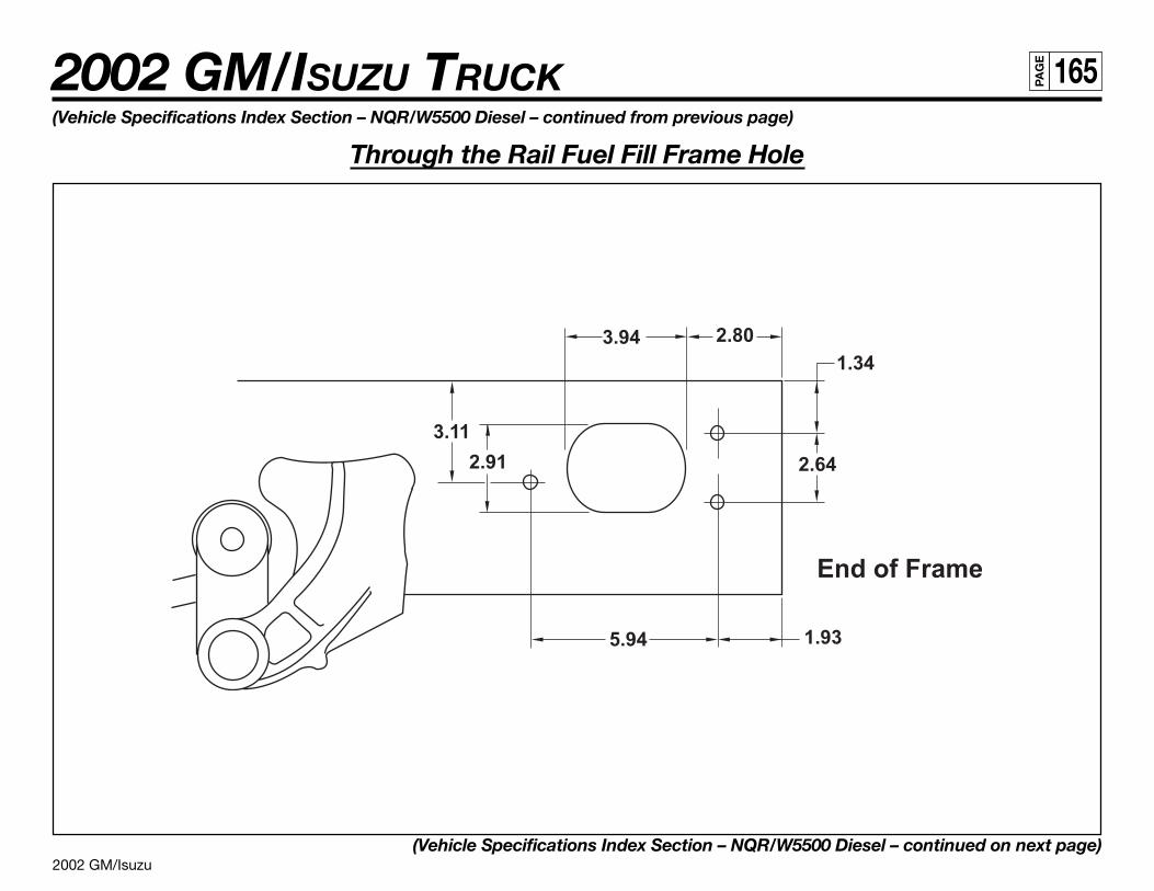
2002 GM/Isuzu
2002 GM/ISUZU TRUCK 165PA
GE
(Vehicle Specifications Index Section – NQR/W5500 Diesel – continued from previous page)
Through the Rail Fuel Fill Frame Hole
(Vehicle Specifications Index Section – NQR/W5500 Diesel – continued on next page)
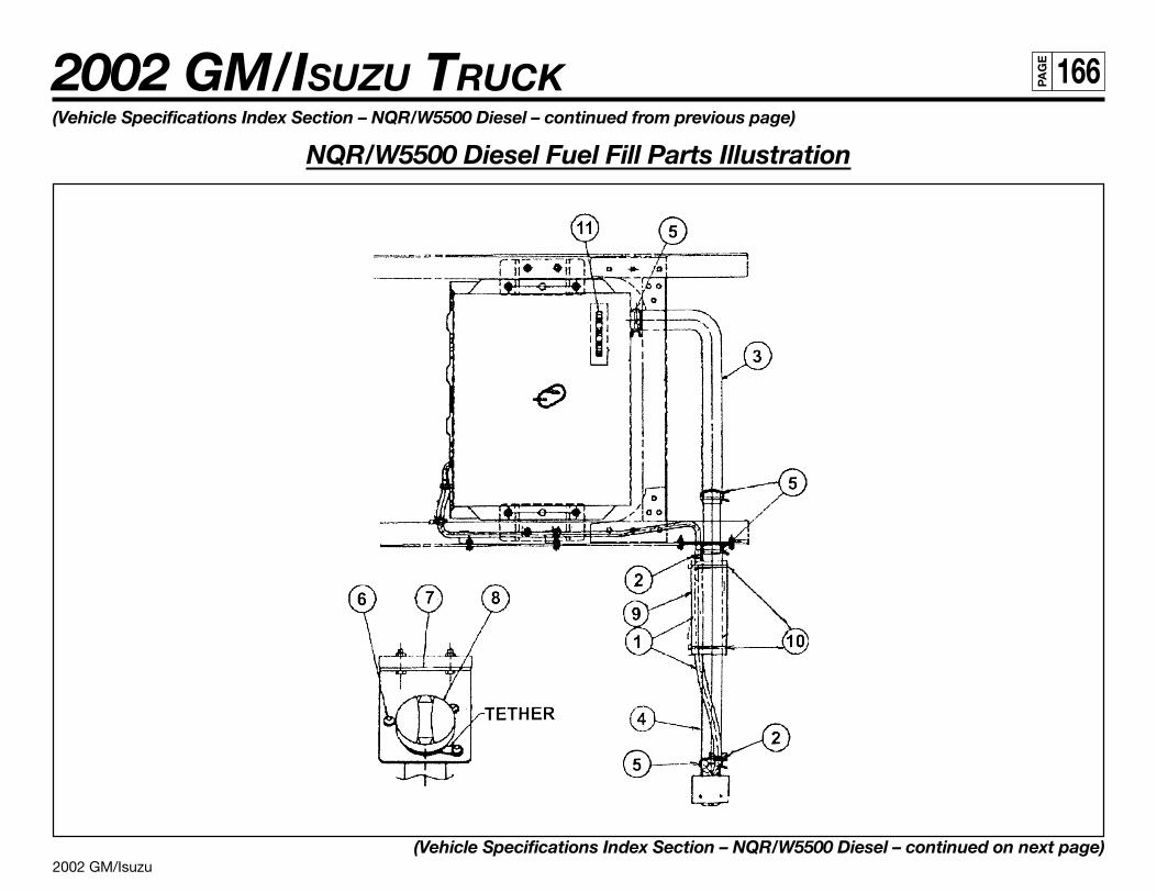
2002 GM/Isuzu
2002 GM/ISUZU TRUCK 166PA
GE
(Vehicle Specifications Index Section – NQR/W5500 Diesel – continued from previous page)
NQR/W5500 Diesel Fuel Fill Parts Illustration
(Vehicle Specifications Index Section – NQR/W5500 Diesel – continued on next page)
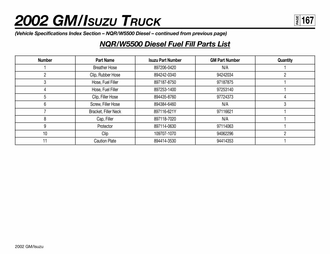
2002 GM/Isuzu
2002 GM/ISUZU TRUCK 167PA
GE
(Vehicle Specifications Index Section – NQR/W5500 Diesel – continued from previous page)
NQR/W5500 Diesel Fuel Fill Parts List
Number Part Name Isuzu Part Number GM Part Number Quantity1 Breather Hose 897206-0420 N/A 1
2 Clip, Rubber Hose 894242-0340 94242034 2
3 Hose, Fuel Filler 897187-8750 97187875 1
4 Hose, Fuel Filler 897253-1400 97253140 1
5 Clip, Filler Hose 894435-8760 97724373 4
6 Screw, Filler Hose 894384-6460 N/A 3
7 Bracket, Filler Neck 897116-621Y 97116621 1
8 Cap, Filler 897118-7020 N/A 1
9 Protector 897114-0630 97114063 1
10 Clip 109707-1070 94062296 2
11 Caution Plate 894414-3530 94414353 1
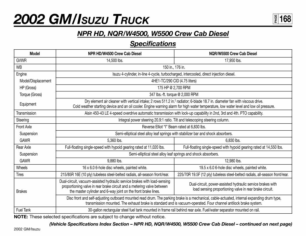
2002 GM/Isuzu
2002 GM/ISUZU TRUCK 168PA
GE
NPR HD, NQR/W4500, W5500 Crew Cab DieselSpecifications
Model NPR HD/W4500 Crew Cab Diesel NQR/W5500 Crew Cab DieselGVWR 14,500 lbs. 17,950 lbs.
WB 150 in., 176 in.
Engine lsuzu 4-cylinder, in-line 4-cycle, turbocharged, intercooled, direct injection diesel.
Model/Displacement 4HE1-TC/290 CID (4.75 liters)
HP (Gross) 175 HP @ 2,700 RPM
Torque (Gross) 347 lbs.-ft. torque @ 2,000 RPM
EquipmentDry element air cleaner with vertical intake; 2 rows 511.2 in.2 radiator; 6-blade 18.7 in. diameter fan with viscous drive.
Cold weather starting device and an oil cooler. Engine warning alarm for high water temperature, low water level and low oil pressure.
Transmission Aisin 450-43 LE 4-speed overdrive automatic transmission with lock-up capability in 2nd, 3rd and 4th. PTO capability.
Steering Integral power steering 20.9:1 ratio. Tilt and telescoping steering column.
Front Axle Reverse Elliot “I” Beam rated at 6,830 lbs.
Suspension Semi-elliptical steel alloy leaf springs with stabilizer bar and shock absorbers.
GAWR 5,360 lbs. 6,830 lbs.
Rear Axle Full-floating single-speed with hypoid gearing rated at 11,020 lbs. Full-floating single-speed with hypoid gearing rated at 14,550 lbs.
Suspension Semi-elliptical steel alloy leaf springs and shock absorbers.
GAWR 9,880 lbs. 12,980 lbs.
Wheels 16 x 6.0 6-hole disc wheels, painted white. 19.5 x 6.0 6-hole disc wheels, painted white.
Tires 215/85R 16E (10 ply) tubeless steel-belted radials, all-season front/rear. 225/70R 19.5F (12 ply) tubeless steel-belted radials, all-season front/rear.
Dual-circuit, vacuum-assisted hydraulic service brakes with load-sensingDual-circuit, power-assisted hydraulic service brakes withproportioning valve in rear brake circuit and a metering valve between
load sensing proportioning valve in rear brake circuit.Brakes the master cylinder and 6-way joint on the front brake lines.
Disc front and self-adjusting outboard mounted read drum. The parking brake is a mechanical, cable-actuated, internal expanding drum type,transmission mounted. The exhaust brake is standard and is vacuum-operated. Four channel antilock brake system.
Fuel Tank 30-gallon rectangular steel fuel tank mounted in frame rail behind rear axle. Fuel/water separator mounted on rail.
NOTE: These selected specifications are subject to change without notice.
(Vehicle Specifications Index Section – NPR HD, NQR/W4500, W5500 Crew Cab Diesel – continued on next page)
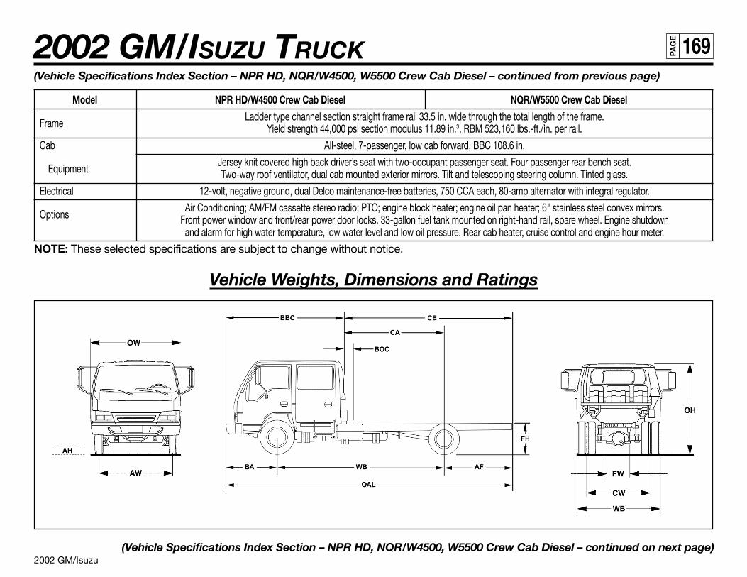
2002 GM/Isuzu
2002 GM/ISUZU TRUCK 169PA
GE
(Vehicle Specifications Index Section – NPR HD, NQR/W4500, W5500 Crew Cab Diesel – continued from previous page)
Model NPR HD/W4500 Crew Cab Diesel NQR/W5500 Crew Cab Diesel
FrameLadder type channel section straight frame rail 33.5 in. wide through the total length of the frame.
Yield strength 44,000 psi section modulus 11.89 in.3, RBM 523,160 lbs.-ft./in. per rail.
Cab All-steel, 7-passenger, low cab forward, BBC 108.6 in.
EquipmentJersey knit covered high back driver’s seat with two-occupant passenger seat. Four passenger rear bench seat.Two-way roof ventilator, dual cab mounted exterior mirrors. Tilt and telescoping steering column. Tinted glass.
Electrical 12-volt, negative ground, dual Delco maintenance-free batteries, 750 CCA each, 80-amp alternator with integral regulator.
OptionsAir Conditioning; AM/FM cassette stereo radio; PTO; engine block heater; engine oil pan heater; 6" stainless steel convex mirrors.
Front power window and front/rear power door locks. 33-gallon fuel tank mounted on right-hand rail, spare wheel. Engine shutdownand alarm for high water temperature, low water level and low oil pressure. Rear cab heater, cruise control and engine hour meter.
NOTE: These selected specifications are subject to change without notice.
Vehicle Weights, Dimensions and Ratings
(Vehicle Specifications Index Section – NPR HD, NQR/W4500, W5500 Crew Cab Diesel – continued on next page)
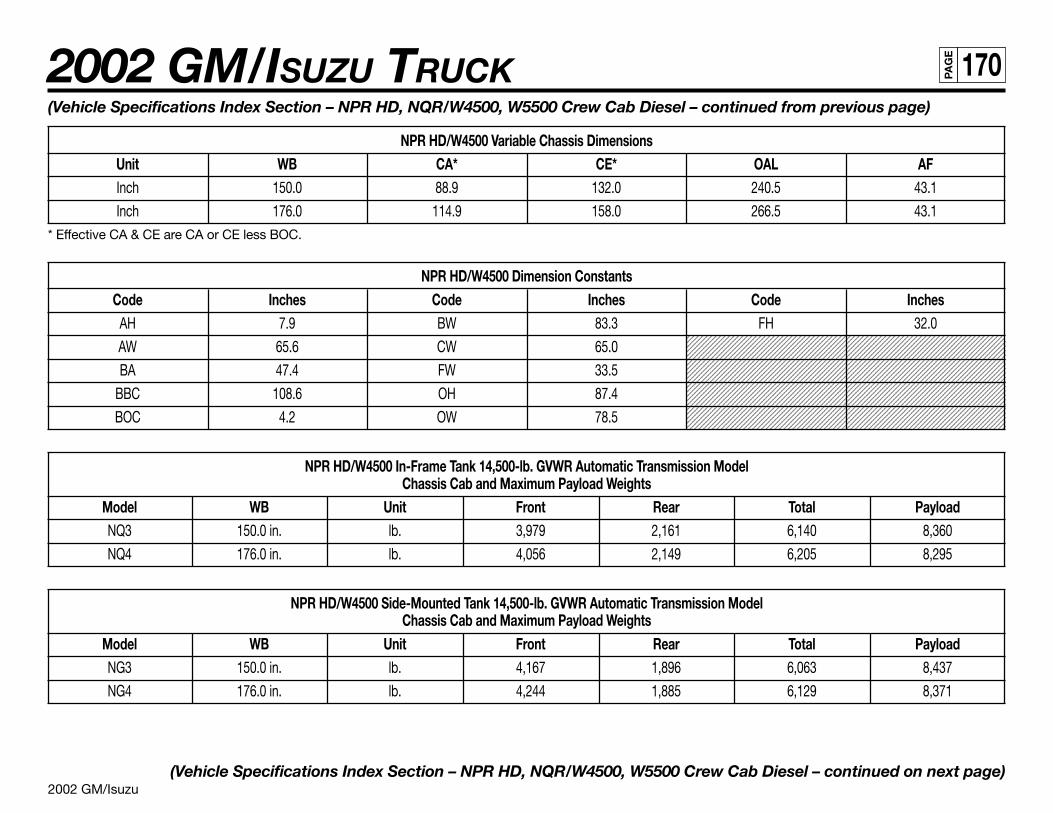
2002 GM/Isuzu
2002 GM/ISUZU TRUCK 170PA
GE
1234567890123456789012345678901212345678901234567890123456789012123456789123456789012345678901234567890121234567890123456789012345678901212345678912345678901234567890123456789012123456789012345678901234567890121234567891234567890123456789012345678901212345678901234567890123456789012123456789123456789012345678901234567890121234567890123456789012345678901212345678912345678901234567890123456789012123456789012345678901234567890121234567891234567890123456789012345678901212345678901234567890123456789012123456789123456789012345678901234567890121234567890123456789012345678901212345678912345678901234567890123456789012123456789012345678901234567890121234567891234567890123456789012345678901212345678901234567890123456789012123456789123456789012345678901234567890121234567890123456789012345678901212345678912345678901234567890123456789012123456789012345678901234567890121234567891234567890123456789012345678901212345678901234567890123456789012123456789123456789012345678901234567890121234567890123456789012345678901212345678912345678901234567890123456789012123456789012345678901234567890121234567891234567890123456789012345678901212345678901234567890123456789012123456789123456789012345678901234567890121234567890123456789012345678901212345678912345678901234567890123456789012123456789012345678901234567890121234567891234567890123456789012345678901212345678901234567890123456789012123456789123456789012345678901234567890121234567890123456789012345678901212345678912345678901234567890123456789012123456789012345678901234567890121234567891234567890123456789012345678901212345678901234567890123456789012123456789
(Vehicle Specifications Index Section – NPR HD, NQR/W4500, W5500 Crew Cab Diesel – continued from previous page)
NPR HD/W4500 Variable Chassis DimensionsUnit WB CA* CE* OAL AFInch 150.0 88.9 132.0 240.5 43.1
Inch 176.0 114.9 158.0 266.5 43.1* Effective CA & CE are CA or CE less BOC.
NPR HD/W4500 Dimension ConstantsCode Inches Code Inches Code Inches
AH 7.9 BW 83.3 FH 32.0
AW 65.6 CW 65.0
BA 47.4 FW 33.5
BBC 108.6 OH 87.4
BOC 4.2 OW 78.5
NPR HD/W4500 In-Frame Tank 14,500-lb. GVWR Automatic Transmission ModelChassis Cab and Maximum Payload Weights
Model WB Unit Front Rear Total PayloadNQ3 150.0 in. lb. 3,979 2,161 6,140 8,360
NQ4 176.0 in. lb. 4,056 2,149 6,205 8,295
NPR HD/W4500 Side-Mounted Tank 14,500-lb. GVWR Automatic Transmission ModelChassis Cab and Maximum Payload Weights
Model WB Unit Front Rear Total PayloadNG3 150.0 in. lb. 4,167 1,896 6,063 8,437
NG4 176.0 in. lb. 4,244 1,885 6,129 8,371
(Vehicle Specifications Index Section – NPR HD, NQR/W4500, W5500 Crew Cab Diesel – continued on next page)
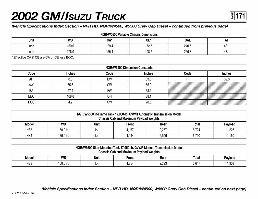
2002 GM/Isuzu
2002 GM/ISUZU TRUCK 171PA
GE
1234567890123456789012345678901212345678901234567890123456789012123456789123456789012345678901234567890121234567890123456789012345678901212345678912345678901234567890123456789012123456789012345678901234567890121234567891234567890123456789012345678901212345678901234567890123456789012123456789123456789012345678901234567890121234567890123456789012345678901212345678912345678901234567890123456789012123456789012345678901234567890121234567891234567890123456789012345678901212345678901234567890123456789012123456789123456789012345678901234567890121234567890123456789012345678901212345678912345678901234567890123456789012123456789012345678901234567890121234567891234567890123456789012345678901212345678901234567890123456789012123456789123456789012345678901234567890121234567890123456789012345678901212345678912345678901234567890123456789012123456789012345678901234567890121234567891234567890123456789012345678901212345678901234567890123456789012123456789123456789012345678901234567890121234567890123456789012345678901212345678912345678901234567890123456789012123456789012345678901234567890121234567891234567890123456789012345678901212345678901234567890123456789012123456789123456789012345678901234567890121234567890123456789012345678901212345678912345678901234567890123456789012123456789012345678901234567890121234567891234567890123456789012345678901212345678901234567890123456789012123456789123456789012345678901234567890121234567890123456789012345678901212345678912345678901234567890123456789012123456789012345678901234567890121234567891234567890123456789012345678901212345678901234567890123456789012123456789
(Vehicle Specifications Index Section – NPR HD, NQR/W4500, W5500 Crew Cab Diesel – continued from previous page)
NQR/W5500 Variable Chassis DimensionsUnit WB CA* CE* OAL AFInch 150.0 129.4 172.5 240.5 43.1
Inch 176.0 155.4 198.5 266.3 43.1* Effective CA & CE are CA or CE less BOC.
NQR/W5500 Dimension ConstantsCode Inches Code Inches Code Inches
AH 8.6 BW 83.3 FH 32.8
AW 65.6 CW 65.0
BA 47.4 FW 33.5
BBC 108.6 OH 88.1
BOC 4.2 OW 78.5
NQR/W5500 In-Frame Tank 17,950-lb. GVWR Automatic Transmission ModelChassis Cab and Maximum Payload Weights
Model WB Unit Front Rear Total PayloadNS3 150.0 in. lb. 4,167 2,257 6,724 11,226
NS4 176.0 in. lb. 4,244 2,546 6,790 11,160
NQR/W5500 Side-Mounted Tank 17,950-lb. GVWR Manual Transmission ModelChassis Cab and Maximum Payload Weights
Model WB Unit Front Rear Total PayloadNS3 150.0 in. lb. 4,354 2,293 6,647 11,303
(Vehicle Specifications Index Section – NPR HD, NQR/W4500, W5500 Crew Cab Diesel – continued on next page)
2002 GM/Isuzu
2002 GM/ISUZU TRUCK 172PA
GE
(Vehicle Specifications Index Section – NPR HD, NQR/W4500, W5500 Crew Cab Diesel – continued from previous page)
Vehicle Weight Limits:
NPR HD/W4500 NQR/W5500
GVWR Designed Maximum 14,500 lbs. 17,950 lbs.
GAWR, Front 5,360 lbs. 6,830 lbs.
GAWR, Rear 9,880 lbs. 12,980 lbs.
Technical Notes:
Chassis Curb Weight reflects standard equipment and fuel. Does not include driver, passenger, payload, body or special equipment.
Maximum Payload Weight is the allowed maximum for equipment, body, payload, driver and passengers and is calculated by subtractingchassis curb weight from the GVWR.
(Vehicle Specifications Index Section – NPR HD, NQR/W4500, W5500 Crew Cab Diesel – continued on next page)
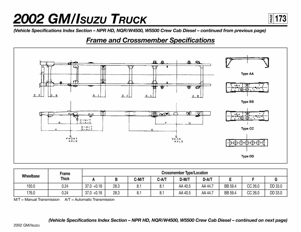
2002 GM/Isuzu
2002 GM/ISUZU TRUCK 173PA
GE
Wheelbase Frame Crossmember Type/LocationThick A B C-M/T C-A/T D-M/T D-A/T E F G
150.0 0.24 37.0 +0.18 28.3 8.1 8.1 AA 40.5 AA 44.7 BB 59.4 CC 26.0 DD 33.0
176.0 0.24 37.0 +0.18 28.3 8.1 8.1 AA 40.5 AA 44.7 BB 59.4 CC 26.0 DD 33.0M/T = Manual Transmission A/T = Automatic Transmission
(Vehicle Specifications Index Section – NPR HD, NQR/W4500, W5500 Crew Cab Diesel – continued on next page)
(Vehicle Specifications Index Section – NPR HD, NQR/W4500, W5500 Crew Cab Diesel – continued from previous page)
Frame and Crossmember Specifications
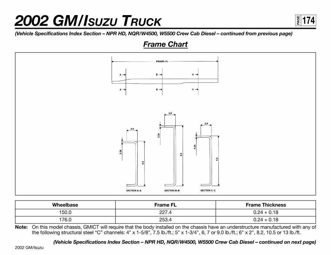
2002 GM/Isuzu
2002 GM/ISUZU TRUCK 174PA
GE
(Vehicle Specifications Index Section – NPR HD, NQR/W4500, W5500 Crew Cab Diesel – continued from previous page)
Frame Chart
Wheelbase Frame FL Frame Thickness150.0 227.4 0.24 + 0.18
176.0 253.4 0.24 + 0.18
Note: On this model chassis, GMICT will require that the body installed on the chassis have an understructure manufactured with any ofthe following structural steel “C” channels: 4" x 1-5/8", 7.5 lb./ft.; 5" x 1-3/4", 6, 7 or 9.0 lb./ft.; 6" x 2", 8.2, 10.5 or 13 lb./ft.
(Vehicle Specifications Index Section – NPR HD, NQR/W4500, W5500 Crew Cab Diesel – continued on next page)
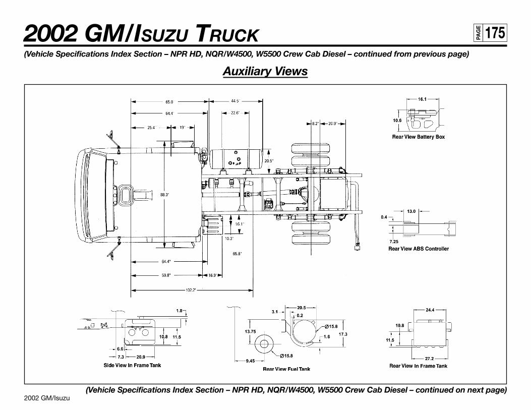
2002 GM/Isuzu
2002 GM/ISUZU TRUCK 175PA
GE
(Vehicle Specifications Index Section – NPR HD, NQR/W4500, W5500 Crew Cab Diesel – continued from previous page)
Auxiliary Views
(Vehicle Specifications Index Section – NPR HD, NQR/W4500, W5500 Crew Cab Diesel – continued on next page)
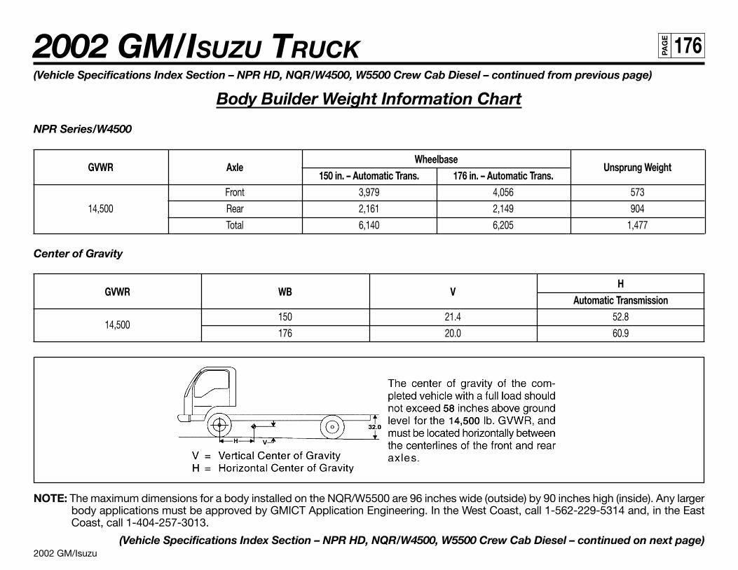
2002 GM/Isuzu
2002 GM/ISUZU TRUCK 176PA
GE
(Vehicle Specifications Index Section – NPR HD, NQR/W4500, W5500 Crew Cab Diesel – continued from previous page)
Body Builder Weight Information Chart
NPR Series/W4500
GVWR AxleWheelbase
Unsprung Weight150 in. – Automatic Trans. 176 in. – Automatic Trans.
Front 3,979 4,056 573
14,500 Rear 2,161 2,149 904
Total 6,140 6,205 1,477
Center of Gravity
GVWR WB VH
Automatic Transmission
14,500150 21.4 52.8
176 20.0 60.9
NOTE: The maximum dimensions for a body installed on the NQR/W5500 are 96 inches wide (outside) by 90 inches high (inside). Any largerbody applications must be approved by GMICT Application Engineering. In the West Coast, call 1-562-229-5314 and, in the EastCoast, call 1-404-257-3013.
(Vehicle Specifications Index Section – NPR HD, NQR/W4500, W5500 Crew Cab Diesel – continued on next page)
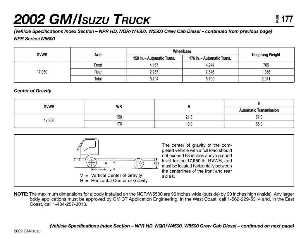
2002 GM/Isuzu
2002 GM/ISUZU TRUCK 177PA
GE
(Vehicle Specifications Index Section – NPR HD, NQR/W4500, W5500 Crew Cab Diesel – continued from previous page)
NPR Series/W5500
GVWR AxleWheelbase
Unsprung Weight150 in. – Automatic Trans. 176 in. – Automatic Trans.
Front 4,167 4,244 705
17,950 Rear 2,257 2,546 1,366
Total 6,724 6,790 2,071
Center of Gravity
GVWR WB VH
Automatic Transmission
17,950150 21.3 57.0
176 19.9 66.0
NOTE: The maximum dimensions for a body installed on the NQR/W5500 are 96 inches wide (outside) by 90 inches high (inside). Any largerbody applications must be approved by GMICT Application Engineering. In the West Coast, call 1-562-229-5314 and, in the EastCoast, call 1-404-257-3013.
(Vehicle Specifications Index Section – NPR HD, NQR/W4500, W5500 Crew Cab Diesel – continued on next page)
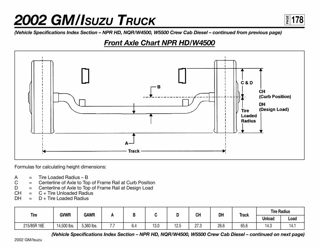
2002 GM/Isuzu
2002 GM/ISUZU TRUCK 178PA
GE
Formulas for calculating height dimensions:
A = Tire Loaded Radius – BC = Centerline of Axle to Top of Frame Rail at Curb PositionD = Centerline of Axle to Top of Frame Rail at Design LoadCH = C + Tire Unloaded RadiusDH = D + Tire Loaded Radius
Tire GVWR GAWR A B C D CH DH TrackTire Radius
Unload Load215/85R 16E 14,500 lbs. 5,360 lbs. 7.7 6.4 13.0 12.5 27.3 26.6 65.6 14.3 14.1
(Vehicle Specifications Index Section – NPR HD, NQR/W4500, W5500 Crew Cab Diesel – continued on next page)
(Vehicle Specifications Index Section – NPR HD, NQR/W4500, W5500 Crew Cab Diesel – continued from previous page)
Front Axle Chart NPR HD/W4500
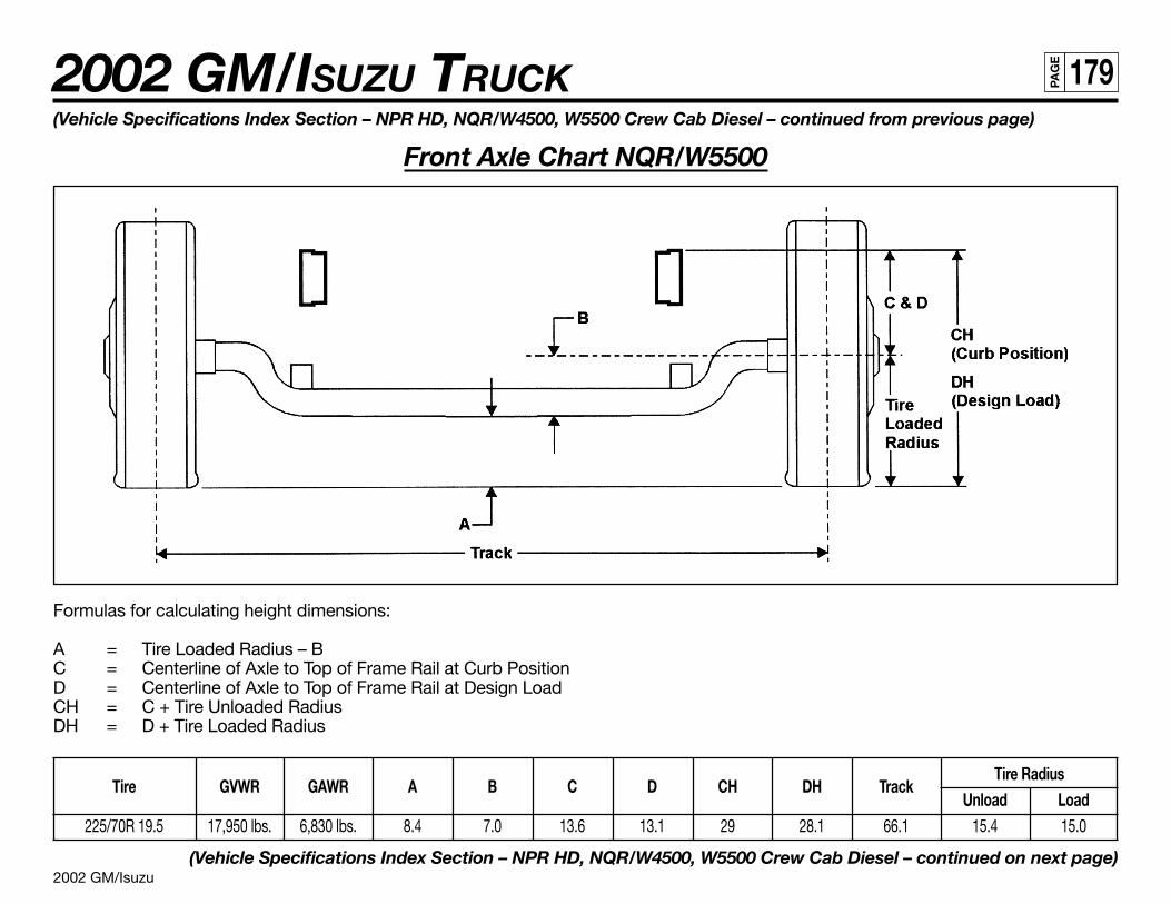
2002 GM/Isuzu
2002 GM/ISUZU TRUCK 179PA
GE
(Vehicle Specifications Index Section – NPR HD, NQR/W4500, W5500 Crew Cab Diesel – continued from previous page)
Front Axle Chart NQR/W5500
Formulas for calculating height dimensions:
A = Tire Loaded Radius – BC = Centerline of Axle to Top of Frame Rail at Curb PositionD = Centerline of Axle to Top of Frame Rail at Design LoadCH = C + Tire Unloaded RadiusDH = D + Tire Loaded Radius
Tire GVWR GAWR A B C D CH DH TrackTire Radius
Unload Load225/70R 19.5 17,950 lbs. 6,830 lbs. 8.4 7.0 13.6 13.1 29 28.1 66.1 15.4 15.0
(Vehicle Specifications Index Section – NPR HD, NQR/W4500, W5500 Crew Cab Diesel – continued on next page)
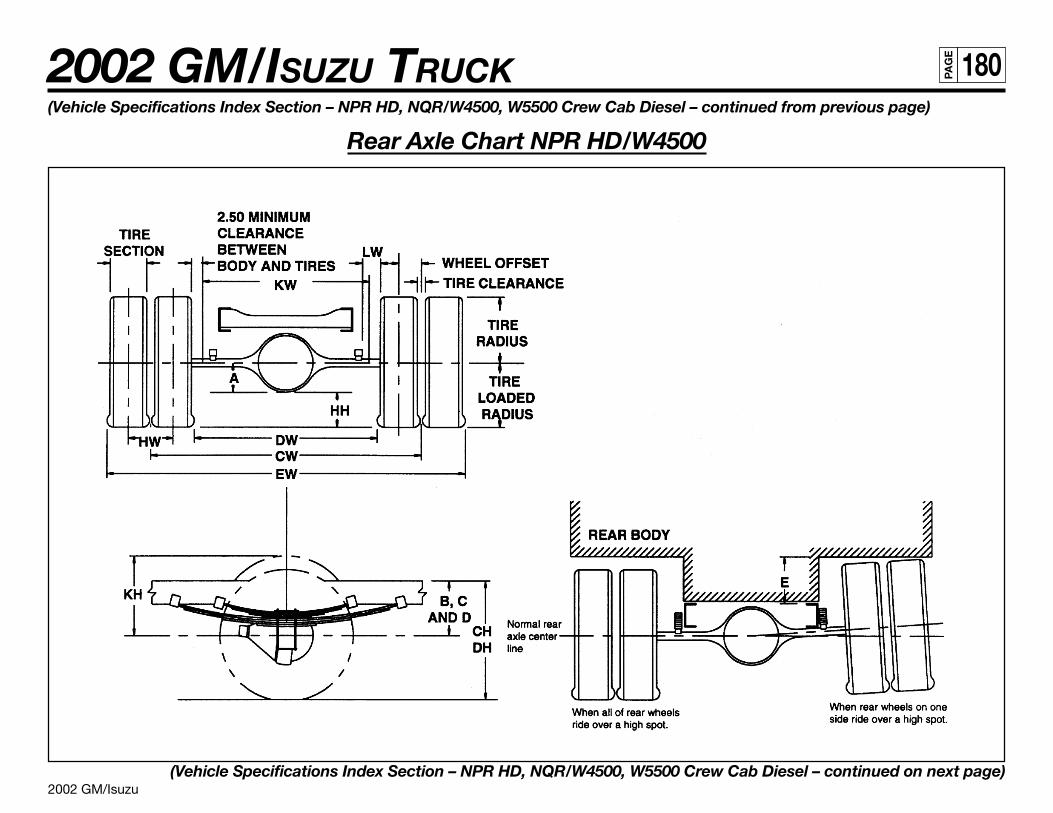
2002 GM/Isuzu
2002 GM/ISUZU TRUCK 180PA
GE
(Vehicle Specifications Index Section – NPR HD, NQR/W4500, W5500 Crew Cab Diesel – continued from previous page)
Rear Axle Chart NPR HD/W4500
(Vehicle Specifications Index Section – NPR HD, NQR/W4500, W5500 Crew Cab Diesel – continued on next page)

2002 GM/Isuzu
2002 GM/ISUZU TRUCK 181PA
GE
(Vehicle Specifications Index Section – NPR HD, NQR/W4500, W5500 Crew Cab Diesel – continued from previous page)
DefinitionsRear Frame Height:
A Centerline of axle to bottom of axle bowl. DH Vertical distance between the normal top of frame rail and the ground-linethrough the centerline of the rear axle at design load.
B Centerline of axle to top of frame rail at metal-to-metal position. DW Minimum distance between the inner surfaces of the rear tires.
C Centerline of axle to top of frame rail at curb position. EWMaximum Rear Width:Overall width of the vehicle measured at the outermost surface of the rear tires.
D Centerline of axle to top of frame rail at design load. HHRear Tire Clearance:Minimum clearance between the rear axle and the ground-line.
Rear Tire Clearance: Dual Tire Spacing:
EMinimum clearance required for tires and chain measured from the top of
HWDistance between the centerlines of the minimum distance required for tire
the frame at the vertical centerline of the rear axle, when rear wheels on bounce as measured from the centerline of the rear axle and the top of theone side ride over a high spot. rear tire when one wheel rides over a high spot.
Rear Frame Height: Track Dual Rear Wheel Vehicles:CH Vertical distance between the normal top of frame rail and the ground-line CW Distance between the centerlines of the dual wheels measured at the
through the centerline of the rear axle at curb position. ground-line.
Tire Section, Tire Radius, Tire Loaded Radius, Tire Clearance See Tire Chart for Values
Formulas for Calculating Rear Width and Height DimensionsCW = Track HH = Tire loaded radius – A
CH = Tire loaded radius + C JH = KH – B
DH = Tire loaded radius + D KH = Tire radius + 3.00 inches
DW = Track + 2 tire sections – tire clearance KW = DW – 5.00 inches
EW = Track + 2 tire sections + tire clearance LW = 1.00-inch minimum clearance between tires and springs
NOTE: Track and overall width may vary with optional equipment.
Tire GAWR Track CW A B C D E215/85R 16E 9,880 lbs. 65.0 10.6 10.6 14.9 13.3 7.8
(Vehicle Specifications Index Section – NPR HD, NQR/W4500, W5500 Crew Cab Diesel – continued on next page)
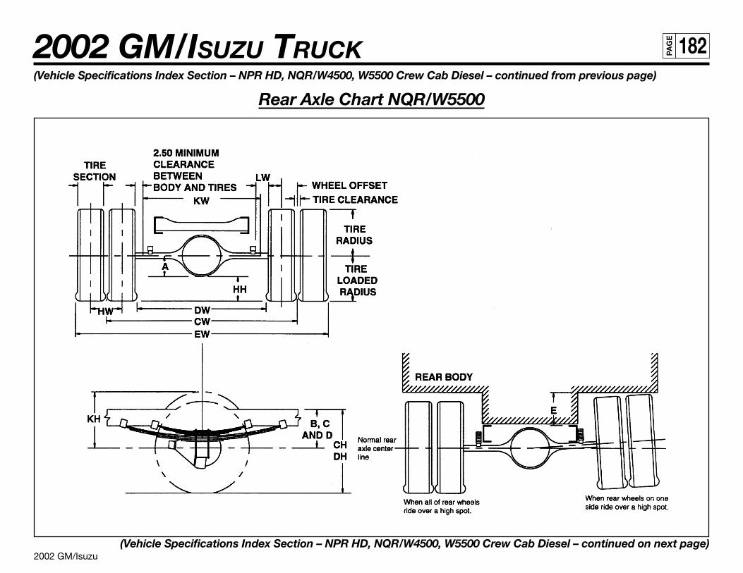
2002 GM/Isuzu
2002 GM/ISUZU TRUCK 182PA
GE
(Vehicle Specifications Index Section – NPR HD, NQR/W4500, W5500 Crew Cab Diesel – continued from previous page)
Rear Axle Chart NQR/W5500
(Vehicle Specifications Index Section – NPR HD, NQR/W4500, W5500 Crew Cab Diesel – continued on next page)
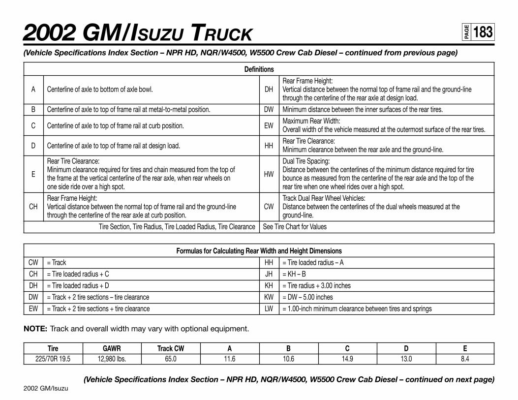
2002 GM/Isuzu
2002 GM/ISUZU TRUCK 183PA
GE
(Vehicle Specifications Index Section – NPR HD, NQR/W4500, W5500 Crew Cab Diesel – continued from previous page)
DefinitionsRear Frame Height:
A Centerline of axle to bottom of axle bowl. DH Vertical distance between the normal top of frame rail and the ground-linethrough the centerline of the rear axle at design load.
B Centerline of axle to top of frame rail at metal-to-metal position. DW Minimum distance between the inner surfaces of the rear tires.
C Centerline of axle to top of frame rail at curb position. EWMaximum Rear Width:Overall width of the vehicle measured at the outermost surface of the rear tires.
D Centerline of axle to top of frame rail at design load. HHRear Tire Clearance:Minimum clearance between the rear axle and the ground-line.
Rear Tire Clearance: Dual Tire Spacing:
EMinimum clearance required for tires and chain measured from the top of
HWDistance between the centerlines of the minimum distance required for tire
the frame at the vertical centerline of the rear axle, when rear wheels on bounce as measured from the centerline of the rear axle and the top of theone side ride over a high spot. rear tire when one wheel rides over a high spot.
Rear Frame Height: Track Dual Rear Wheel Vehicles:CH Vertical distance between the normal top of frame rail and the ground-line CW Distance between the centerlines of the dual wheels measured at the
through the centerline of the rear axle at curb position. ground-line.
Tire Section, Tire Radius, Tire Loaded Radius, Tire Clearance See Tire Chart for Values
Formulas for Calculating Rear Width and Height DimensionsCW = Track HH = Tire loaded radius – A
CH = Tire loaded radius + C JH = KH – B
DH = Tire loaded radius + D KH = Tire radius + 3.00 inches
DW = Track + 2 tire sections – tire clearance KW = DW – 5.00 inches
EW = Track + 2 tire sections + tire clearance LW = 1.00-inch minimum clearance between tires and springs
NOTE: Track and overall width may vary with optional equipment.
Tire GAWR Track CW A B C D E225/70R 19.5 12,980 lbs. 65.0 11.6 10.6 14.9 13.0 8.4
(Vehicle Specifications Index Section – NPR HD, NQR/W4500, W5500 Crew Cab Diesel – continued on next page)
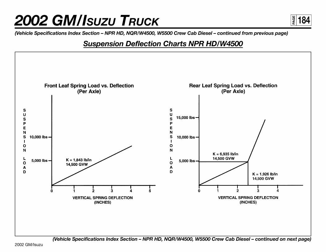
2002 GM/Isuzu
2002 GM/ISUZU TRUCK 184PA
GE
(Vehicle Specifications Index Section – NPR HD, NQR/W4500, W5500 Crew Cab Diesel – continued from previous page)
Suspension Deflection Charts NPR HD/W4500
(Vehicle Specifications Index Section – NPR HD, NQR/W4500, W5500 Crew Cab Diesel – continued on next page)
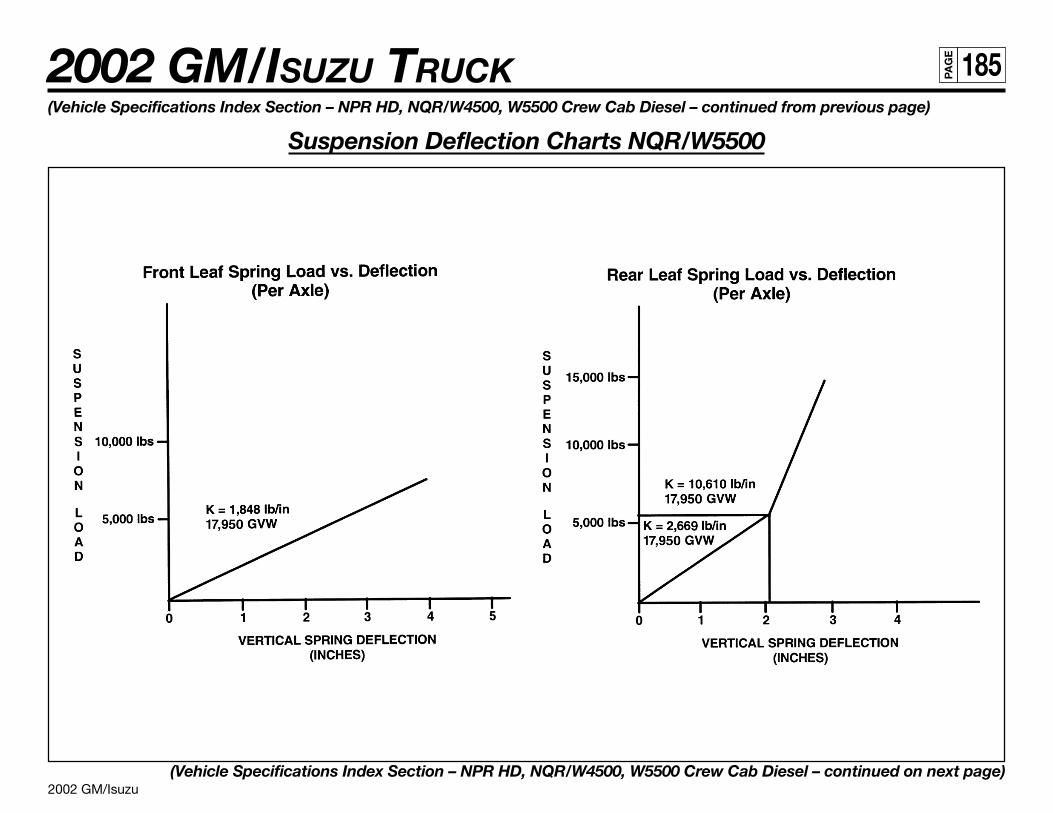
2002 GM/Isuzu
2002 GM/ISUZU TRUCK 185PA
GE
(Vehicle Specifications Index Section – NPR HD, NQR/W4500, W5500 Crew Cab Diesel – continued from previous page)
Suspension Deflection Charts NQR/W5500
(Vehicle Specifications Index Section – NPR HD, NQR/W4500, W5500 Crew Cab Diesel – continued on next page)
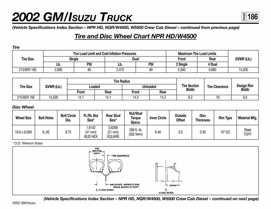
2002 GM/Isuzu
2002 GM/ISUZU TRUCK 186PA
GE
(Vehicle Specifications Index Section – NPR HD, NQR/W4500, W5500 Crew Cab Diesel – continued from previous page)
Tire and Disc Wheel Chart NPR HD/W4500
Tire
Tire Load Limit and Cold Inflation Pressures Maximum Tire Load LimitsTire Size Single Dual Front Rear GVWR (Lb.)
Lb. PSI Lb. PSI 2 Single 4 Dual215/85R 16E 2,680 80 2,470 80 5,360 9,880 14,500
Tire RadiusTire Section Design RimTire Size GVWR (Lb.) Loaded Unloaded
WidthTire Clearance
WidthFront Rear Front Rear215/85R 16E 14,500 14.1 14.1 14.3 14.3 8.2 18 6.0
Disc Wheel
Bolt Circle Ft./Rr. Nut Rear Stud Nut/Stud Outside DiscWheel Size Bolt Holes Dia. Size* Size* Torque Inner Circle Offset Thickness Rim Type Material Mfg.Specs.
1.6142 0.8268 289 ft.-lb. Steel16.6 x 6.00K 6 JIS 8.75 (41 mm) (21 mm) (392 N•m) 6.46 5.0 0.39 15º DC TOPYBUD HEX SQUARE
* O.D. Wrench Sizes
(Vehicle Specifications Index Section – NPR HD, NQR/W4500, W5500 Crew Cab Diesel – continued on next page)
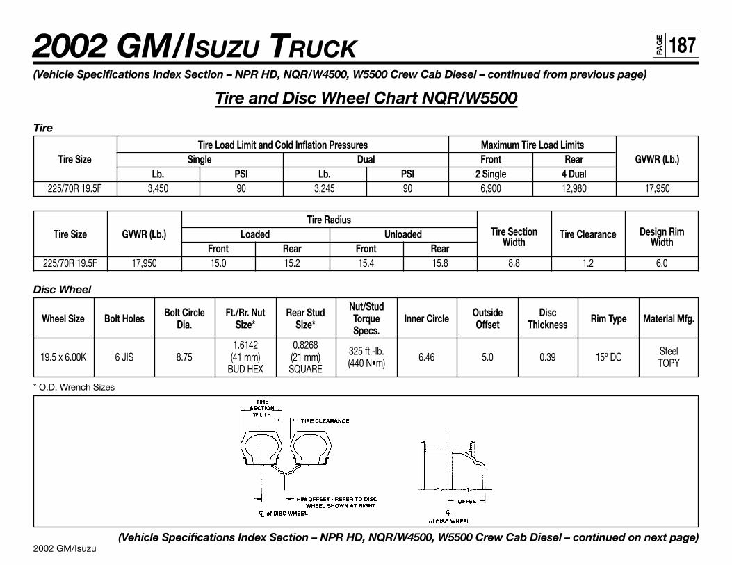
2002 GM/Isuzu
2002 GM/ISUZU TRUCK 187PA
GE
(Vehicle Specifications Index Section – NPR HD, NQR/W4500, W5500 Crew Cab Diesel – continued from previous page)
Tire and Disc Wheel Chart NQR/W5500
Tire
Tire Load Limit and Cold Inflation Pressures Maximum Tire Load LimitsTire Size Single Dual Front Rear GVWR (Lb.)
Lb. PSI Lb. PSI 2 Single 4 Dual225/70R 19.5F 3,450 90 3,245 90 6,900 12,980 17,950
Tire RadiusTire Section Design RimTire Size GVWR (Lb.) Loaded Unloaded
WidthTire Clearance
WidthFront Rear Front Rear225/70R 19.5F 17,950 15.0 15.2 15.4 15.8 8.8 1.2 6.0
Disc Wheel
Bolt Circle Ft./Rr. Nut Rear Stud Nut/Stud Outside DiscWheel Size Bolt Holes Dia. Size* Size* Torque Inner Circle Offset Thickness Rim Type Material Mfg.Specs.
1.6142 0.8268 325 ft.-lb. Steel19.5 x 6.00K 6 JIS 8.75 (41 mm) (21 mm) (440 N•m) 6.46 5.0 0.39 15º DC TOPYBUD HEX SQUARE
* O.D. Wrench Sizes
(Vehicle Specifications Index Section – NPR HD, NQR/W4500, W5500 Crew Cab Diesel – continued on next page)
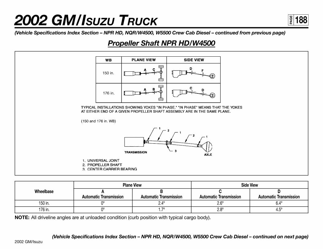
2002 GM/Isuzu
2002 GM/ISUZU TRUCK 188PA
GE
Plane View Side ViewWheelbase A B C D
Automatic Transmission Automatic Transmission Automatic Transmission Automatic Transmission150 in. 0º 2.4º 2.6º 6.4º176 in. 0º 1.7º 2.8º 4.5º
NOTE: All driveline angles are at unloaded condition (curb position with typical cargo body).
(Vehicle Specifications Index Section – NPR HD, NQR/W4500, W5500 Crew Cab Diesel – continued on next page)
(Vehicle Specifications Index Section – NPR HD, NQR/W4500, W5500 Crew Cab Diesel – continued from previous page)
Propeller Shaft NPR HD/W4500
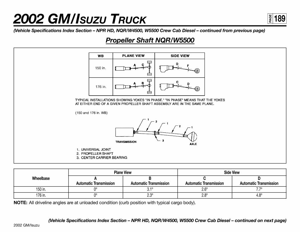
2002 GM/Isuzu
2002 GM/ISUZU TRUCK 189PA
GE
Plane View Side ViewWheelbase A B C D
Automatic Transmission Automatic Transmission Automatic Transmission Automatic Transmission150 in. 0º 3.1º 2.6º 7.7º176 in. 0º 2.3º 2.8º 4.8º
NOTE: All driveline angles are at unloaded condition (curb position with typical cargo body).
(Vehicle Specifications Index Section – NPR HD, NQR/W4500, W5500 Crew Cab Diesel – continued on next page)
(Vehicle Specifications Index Section – NPR HD, NQR/W4500, W5500 Crew Cab Diesel – continued from previous page)
Propeller Shaft NQR/W5500
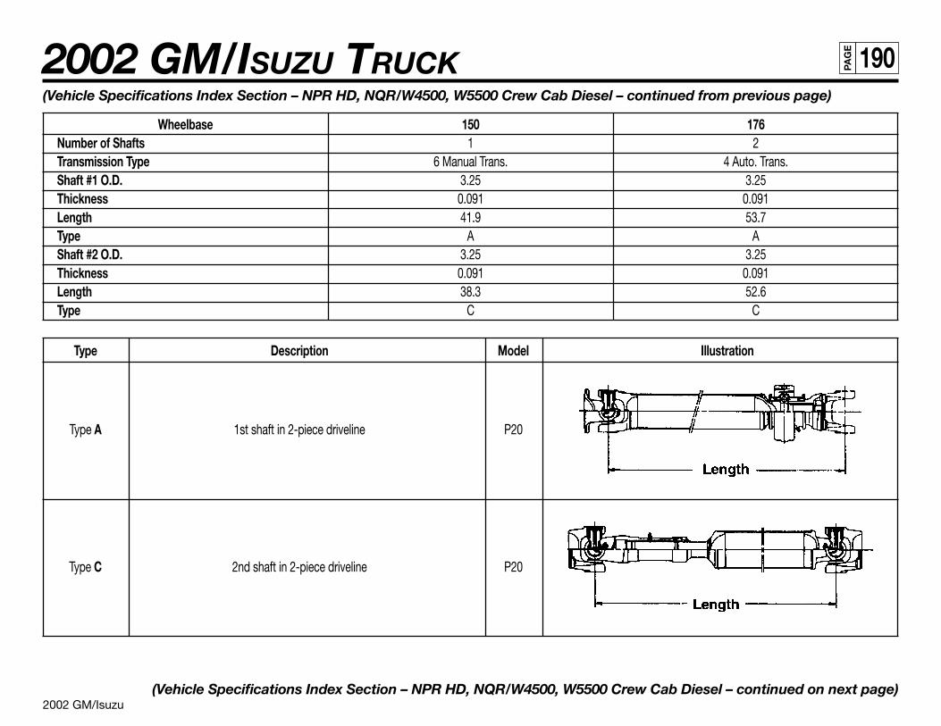
2002 GM/Isuzu
2002 GM/ISUZU TRUCK 190PA
GE
(Vehicle Specifications Index Section – NPR HD, NQR/W4500, W5500 Crew Cab Diesel – continued from previous page)
Wheelbase 150 176Number of Shafts 1 2Transmission Type 6 Manual Trans. 4 Auto. Trans.Shaft #1 O.D. 3.25 3.25Thickness 0.091 0.091Length 41.9 53.7Type A AShaft #2 O.D. 3.25 3.25Thickness 0.091 0.091Length 38.3 52.6Type C C
Type Description Model Illustration
Type A 1st shaft in 2-piece driveline P20
Type C 2nd shaft in 2-piece driveline P20
(Vehicle Specifications Index Section – NPR HD, NQR/W4500, W5500 Crew Cab Diesel – continued on next page)
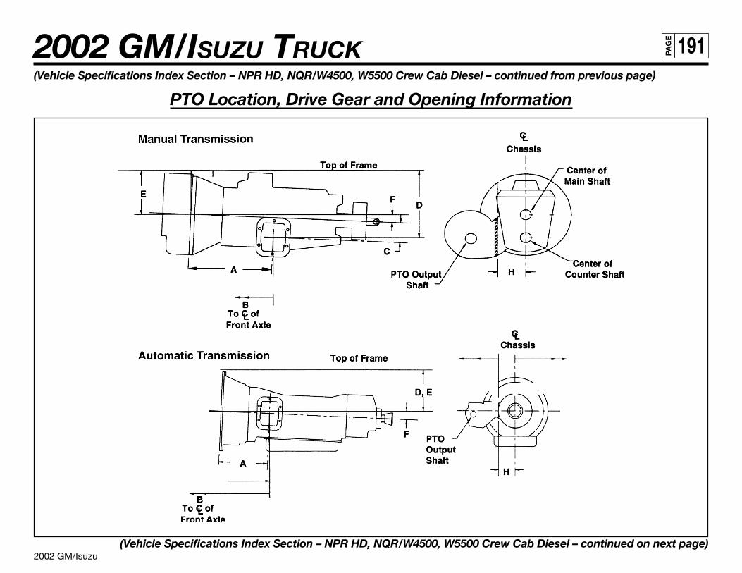
2002 GM/Isuzu
2002 GM/ISUZU TRUCK 191PA
GE
(Vehicle Specifications Index Section – NPR HD, NQR/W4500, W5500 Crew Cab Diesel – continued from previous page)
PTO Location, Drive Gear and Opening Information
(Vehicle Specifications Index Section – NPR HD, NQR/W4500, W5500 Crew Cab Diesel – continued on next page)
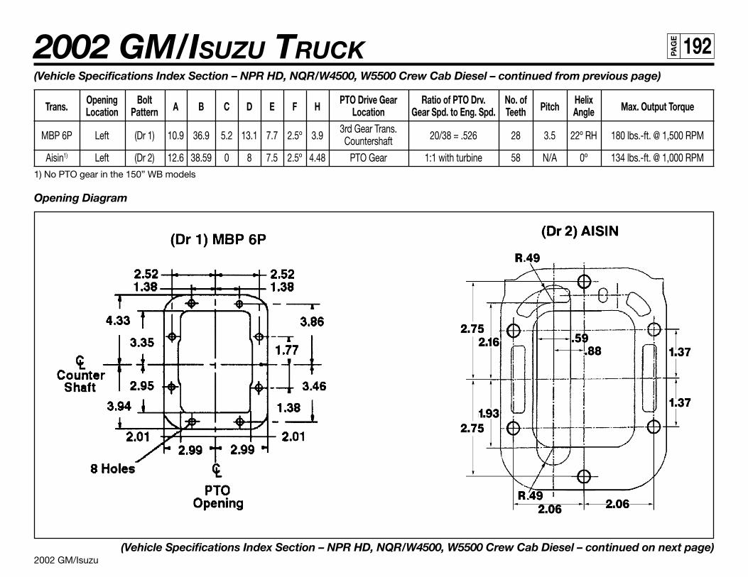
2002 GM/Isuzu
2002 GM/ISUZU TRUCK 192PA
GE
(Vehicle Specifications Index Section – NPR HD, NQR/W4500, W5500 Crew Cab Diesel – continued from previous page)
Trans.Opening Bolt
A B C D E F HPTO Drive Gear Ratio of PTO Drv. No. of
PitchHelix
Max. Output TorqueLocation Pattern Location Gear Spd. to Eng. Spd. Teeth Angle
MBP 6P Left (Dr 1) 10.9 36.9 5.2 13.1 7.7 2.5º 3.93rd Gear Trans.
20/38 = .526 28 3.5 22º RH 180 lbs.-ft. @ 1,500 RPMCountershaft
Aisin1) Left (Dr 2) 12.6 38.59 0 8 7.5 2.5º 4.48 PTO Gear 1:1 with turbine 58 N/A 0º 134 lbs.-ft. @ 1,000 RPM1) No PTO gear in the 150” WB models
Opening Diagram
(Vehicle Specifications Index Section – NPR HD, NQR/W4500, W5500 Crew Cab Diesel – continued on next page)
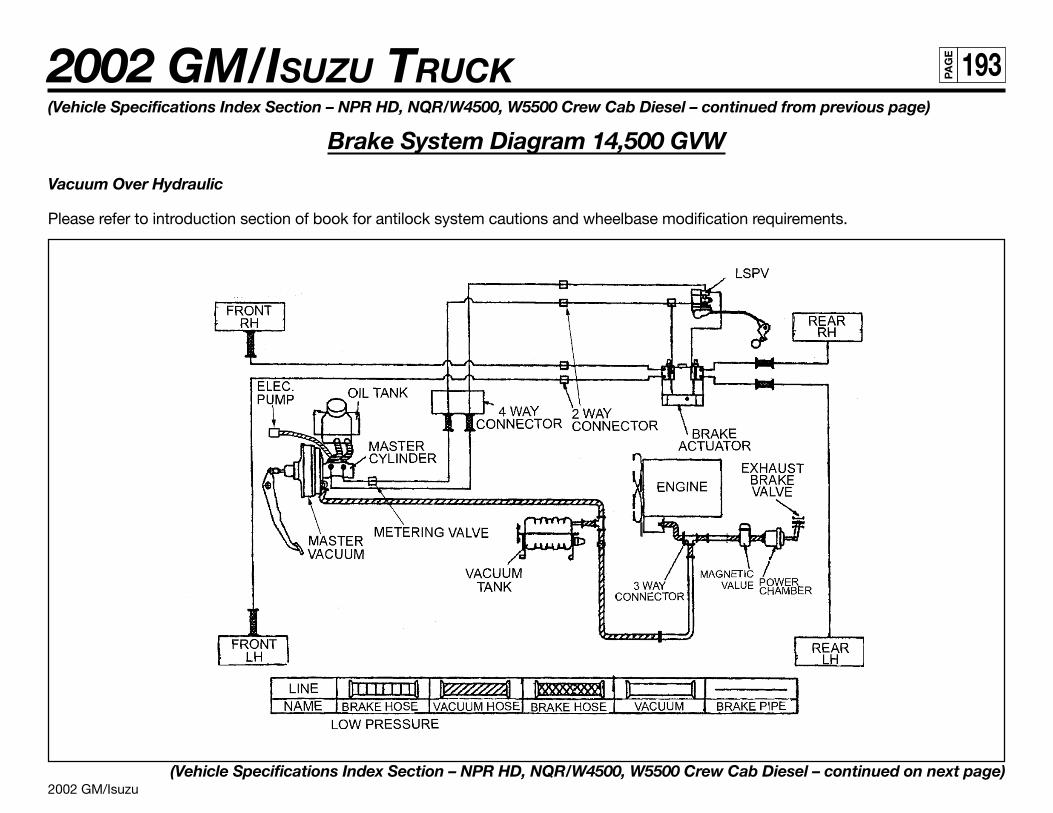
2002 GM/Isuzu
2002 GM/ISUZU TRUCK 193PA
GE
(Vehicle Specifications Index Section – NPR HD, NQR/W4500, W5500 Crew Cab Diesel – continued from previous page)
Brake System Diagram 14,500 GVW
Vacuum Over Hydraulic
Please refer to introduction section of book for antilock system cautions and wheelbase modification requirements.
(Vehicle Specifications Index Section – NPR HD, NQR/W4500, W5500 Crew Cab Diesel – continued on next page)
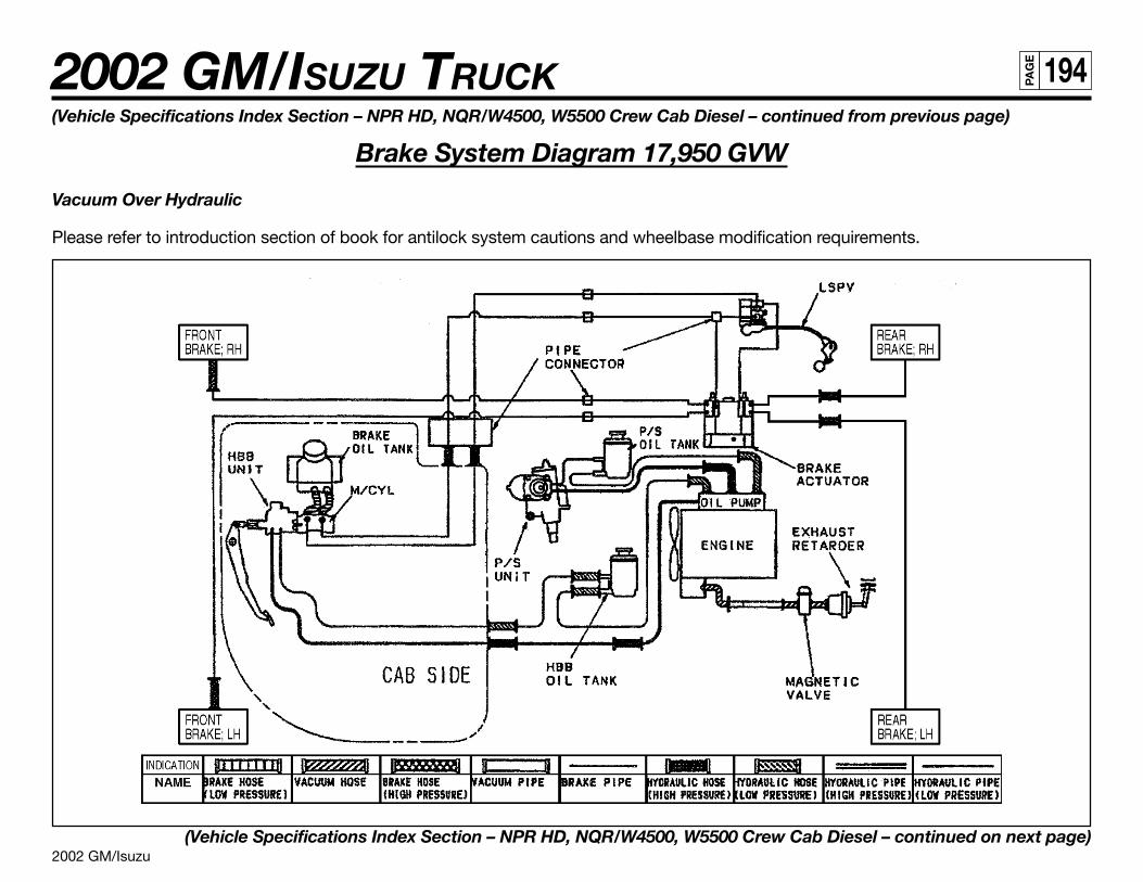
2002 GM/Isuzu
2002 GM/ISUZU TRUCK 194PA
GE
(Vehicle Specifications Index Section – NPR HD, NQR/W4500, W5500 Crew Cab Diesel – continued from previous page)
Brake System Diagram 17,950 GVW
Vacuum Over Hydraulic
Please refer to introduction section of book for antilock system cautions and wheelbase modification requirements.
(Vehicle Specifications Index Section – NPR HD, NQR/W4500, W5500 Crew Cab Diesel – continued on next page)
2002 GM/Isuzu
2002 GM/ISUZU TRUCK 195PA
GE
(Vehicle Specifications Index Section – NPR HD, NQR/W4500, W5500 Crew Cab Diesel – continued from previous page)
Diesel Fuel Fill
Installation Instructions
1. Disconnect battery.
2. Loosen hose from the tie downs. Remove caps from plate on rail.
3. Install hoses onto the plate.
4. Extend hose out from the driver’s side of the rail to body rail.
5. The filler neck must be mounted to allow the fill plate bracket to be parallel to the frame horizontal (see figure 4).
6. Cover with protector wrap and secure with tie wraps.
7. Filler hose is set for 96 inches outside width body.
8. Filler neck (dimension A) must be between 6.85 inches and 8.5 inches above frame.
9. Secure the filler plate to the bottom of the body and check for leaks.
10. Ensure that fill hose does not sag, creating an area where the fuel could pool in the fill hose.
11. Reconnect battery.
(Vehicle Specifications Index Section – NPR HD, NQR/W4500, W5500 Crew Cab Diesel – continued on next page)
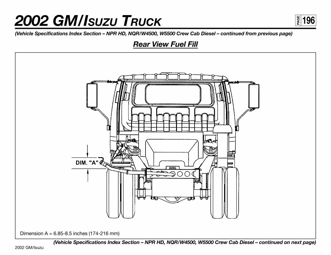
2002 GM/Isuzu
2002 GM/ISUZU TRUCK 196PA
GE
(Vehicle Specifications Index Section – NPR HD, NQR/W4500, W5500 Crew Cab Diesel – continued from previous page)
Rear View Fuel Fill
Dimension A = 6.85-8.5 inches (174-216 mm)
(Vehicle Specifications Index Section – NPR HD, NQR/W4500, W5500 Crew Cab Diesel – continued on next page)
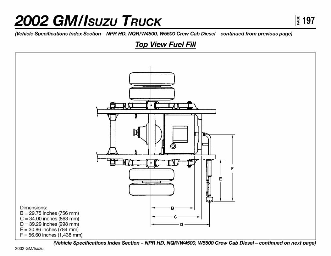
2002 GM/Isuzu
2002 GM/ISUZU TRUCK 197PA
GE
(Vehicle Specifications Index Section – NPR HD, NQR/W4500, W5500 Crew Cab Diesel – continued from previous page)
Top View Fuel Fill
Dimensions:B = 29.75 inches (756 mm)C = 34.00 inches (863 mm)D = 39.29 inches (998 mm)E = 30.86 inches (784 mm)F = 56.60 inches (1,438 mm)
(Vehicle Specifications Index Section – NPR HD, NQR/W4500, W5500 Crew Cab Diesel – continued on next page)
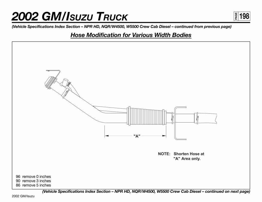
2002 GM/Isuzu
2002 GM/ISUZU TRUCK 198PA
GE
(Vehicle Specifications Index Section – NPR HD, NQR/W4500, W5500 Crew Cab Diesel – continued from previous page)
Hose Modification for Various Width Bodies
96 remove 0 inches90 remove 3 inches86 remove 5 inches
(Vehicle Specifications Index Section – NPR HD, NQR/W4500, W5500 Crew Cab Diesel – continued on next page)
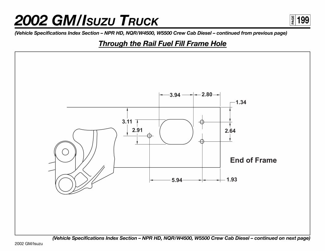
2002 GM/Isuzu
2002 GM/ISUZU TRUCK 199PA
GE
(Vehicle Specifications Index Section – NPR HD, NQR/W4500, W5500 Crew Cab Diesel – continued from previous page)
Through the Rail Fuel Fill Frame Hole
(Vehicle Specifications Index Section – NPR HD, NQR/W4500, W5500 Crew Cab Diesel – continued on next page)
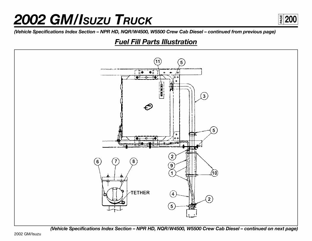
2002 GM/Isuzu
2002 GM/ISUZU TRUCK 200PA
GE
(Vehicle Specifications Index Section – NPR HD, NQR/W4500, W5500 Crew Cab Diesel – continued from previous page)
Fuel Fill Parts Illustration
(Vehicle Specifications Index Section – NPR HD, NQR/W4500, W5500 Crew Cab Diesel – continued on next page)
2002 GM/Isuzu
2002 GM/ISUZU TRUCK 201PA
GE
(Vehicle Specifications Index Section – NPR HD, NQR/W4500, W5500 Crew Cab Diesel – continued from previous page)
Fuel Fill Parts List
Number Part Name Isuzu Part Number GM Part Number Quantity1 Breather Hose 897206-0420 N/A 1
2 Clip, Rubber Hose 894242-0340 94242034 2
3 Hose, Fuel Filler 897187-8750 97187875 1
4 Hose, Fuel Filler 897253-1400 97253140 1
5 Clip, Filler Hose 894435-8760 97724373 4
6 Screw, Filler Hose 894384-6460 N/A 3
7 Bracket, Filler Neck 897116-621Y 97116621 1
8 Cap, Filler 897118-7020 N/A 1
9 Protector 897114-0630 97114063 1
10 Clip 109707-1070 94062296 2
11 Caution Plate 894414-3530 94414353 1
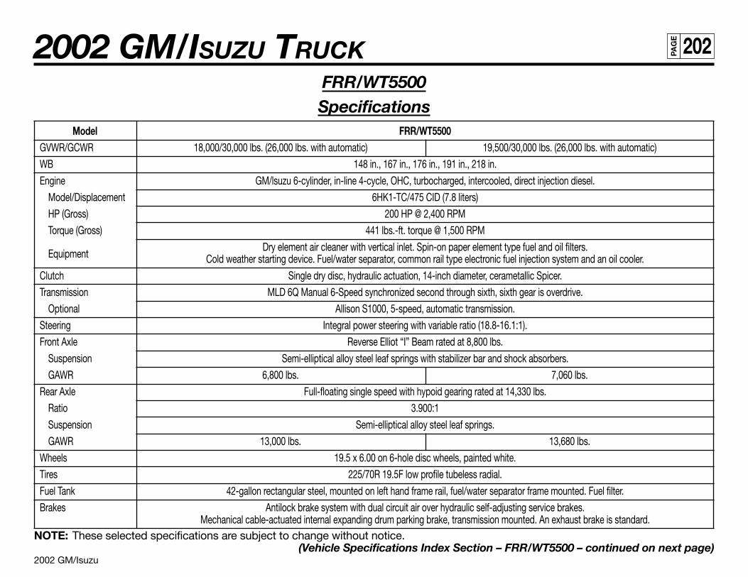
2002 GM/Isuzu
2002 GM/ISUZU TRUCK 202PA
GE
FRR/WT5500Specifications
Model FRR/WT5500GVWR/GCWR 18,000/30,000 lbs. (26,000 lbs. with automatic) 19,500/30,000 lbs. (26,000 lbs. with automatic)
WB 148 in., 167 in., 176 in., 191 in., 218 in.
Engine GM/lsuzu 6-cylinder, in-line 4-cycle, OHC, turbocharged, intercooled, direct injection diesel.
Model/Displacement 6HK1-TC/475 CID (7.8 liters)
HP (Gross) 200 HP @ 2,400 RPM
Torque (Gross) 441 lbs.-ft. torque @ 1,500 RPM
EquipmentDry element air cleaner with vertical inlet. Spin-on paper element type fuel and oil filters.
Cold weather starting device. Fuel/water separator, common rail type electronic fuel injection system and an oil cooler.
Clutch Single dry disc, hydraulic actuation, 14-inch diameter, cerametallic Spicer.
Transmission MLD 6Q Manual 6-Speed synchronized second through sixth, sixth gear is overdrive.
Optional Allison S1000, 5-speed, automatic transmission.
Steering Integral power steering with variable ratio (18.8-16.1:1).
Front Axle Reverse Elliot “I” Beam rated at 8,800 lbs.
Suspension Semi-elliptical alloy steel leaf springs with stabilizer bar and shock absorbers.
GAWR 6,800 lbs. 7,060 lbs.
Rear Axle Full-floating single speed with hypoid gearing rated at 14,330 lbs.
Ratio 3.900:1
Suspension Semi-elliptical alloy steel leaf springs.
GAWR 13,000 lbs. 13,680 lbs.
Wheels 19.5 x 6.00 on 6-hole disc wheels, painted white.
Tires 225/70R 19.5F low profile tubeless radial.
Fuel Tank 42-gallon rectangular steel, mounted on left hand frame rail, fuel/water separator frame mounted. Fuel filter.
Brakes Antilock brake system with dual circuit air over hydraulic self-adjusting service brakes.Mechanical cable-actuated internal expanding drum parking brake, transmission mounted. An exhaust brake is standard.
NOTE: These selected specifications are subject to change without notice.(Vehicle Specifications Index Section – FRR/WT5500 – continued on next page)
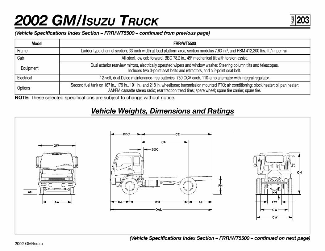
2002 GM/Isuzu
2002 GM/ISUZU TRUCK 203PA
GE
(Vehicle Specifications Index Section – FRR/WT5500 – continued from previous page)
Model FRR/WT5500Frame Ladder type channel section, 33-inch width at load platform area, section modulus 7.63 in.3, and RBM 412,200 lbs.-ft./in. per rail.
Cab All-steel, low cab forward, BBC 78.2 in., 45º mechanical tilt with torsion assist.
EquipmentDual exterior rearview mirrors, electrically operated wipers and window washer. Steering column tilts and telescopes.
Includes two 3-point seat belts and retractors, and a 2-point seat belt.
Electrical 12-volt, dual Delco maintenance-free batteries, 750 CCA each. 110-amp alternator with integral regulator.
OptionsSecond fuel tank on 167 in., 179 in., 191 in., and 218 in. wheelbase; transmission mounted PTO; air conditioning; block heater; oil pan heater;
AM/FM cassette stereo radio; rear traction tread tires; spare wheel; spare tire carrier; spare tire.
NOTE: These selected specifications are subject to change without notice.
Vehicle Weights, Dimensions and Ratings
(Vehicle Specifications Index Section – FRR/WT5500 – continued on next page)
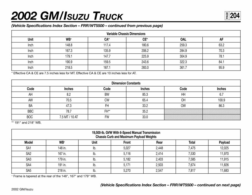
2002 GM/Isuzu
2002 GM/ISUZU TRUCK 204PA
GE
123456789012345678901234567890121234567890123456789012345678901212345678912345678901234567890123456789012123456789012345678901234567890121234567891234567890123456789012345678901212345678901234567890123456789012123456789123456789012345678901234567890121234567890123456789012345678901212345678912345678901234567890123456789012123456789012345678901234567890121234567891234567890123456789012345678901212345678901234567890123456789012123456789123456789012345678901234567890121234567890123456789012345678901212345678912345678901234567890123456789012123456789012345678901234567890121234567891234567890123456789012345678901212345678901234567890123456789012123456789123456789012345678901234567890121234567890123456789012345678901212345678912345678901234567890123456789012123456789012345678901234567890121234567891234567890123456789012345678901212345678901234567890123456789012123456789
(Vehicle Specifications Index Section – FRR/WT5500 – continued from previous page)
Variable Chassis DimensionsUnit WB+ CA* CE* OAL AFInch 148.8 117.4 180.6 259.3 63.2
Inch 167.3 135.9 206.2 284.9 70.3
Inch 179.1 147.7 225.9 304.9 78.1
Inch 190.9 159.5 243.6 322.3 84.1
Inch 218.5 187.1 283.0 361.7 95.9* Effective CA & CE are 7.5 inches less for MT. Effective CA & CE are 10 inches less for AT.
Dimension ConstantsCode Inches Code Inches Code Inches
AH 8.2 BW 85.3 HH 6.7
AW 70.5 CW 65.4 OH 100.9
BA 47.3 FH 33.2 OW 86.3
BBC 78.7 FH** 35.2
BOC 7.5 MT / 10 AT FW 33.0** 191" and 218" WB.
19,500-lb. GVW With 6-Speed Manual TransmissionChassis Curb and Maximum Payload Weights
Model WB+ Unit Front Rear Total PayloadSA1 148 in. lb. 5,027 2,448 7,475 12,025
SA2 167 in. lb. 5,116 2,414 7,530 11,970
SA3 179 in. lb. 5,182 2,403 7,585 11,915
SA4 191 in. lb. 5,171 2,503 7,674 11,826
SA5 218 in. lb. 5,270 2,547 7,817 11,683+ Frame is tapered at the rear of the 148", 167" and 179" WB.
(Vehicle Specifications Index Section – FRR/WT5500 – continued on next page)
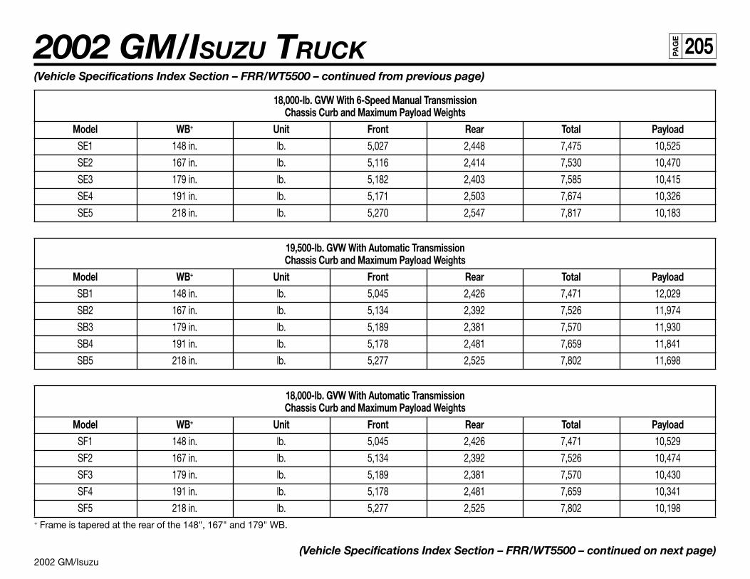
2002 GM/Isuzu
2002 GM/ISUZU TRUCK 205PA
GE
(Vehicle Specifications Index Section – FRR/WT5500 – continued from previous page)
18,000-lb. GVW With 6-Speed Manual TransmissionChassis Curb and Maximum Payload Weights
Model WB+ Unit Front Rear Total PayloadSE1 148 in. lb. 5,027 2,448 7,475 10,525
SE2 167 in. lb. 5,116 2,414 7,530 10,470
SE3 179 in. lb. 5,182 2,403 7,585 10,415
SE4 191 in. lb. 5,171 2,503 7,674 10,326
SE5 218 in. lb. 5,270 2,547 7,817 10,183
19,500-lb. GVW With Automatic TransmissionChassis Curb and Maximum Payload Weights
Model WB+ Unit Front Rear Total PayloadSB1 148 in. lb. 5,045 2,426 7,471 12,029
SB2 167 in. lb. 5,134 2,392 7,526 11,974
SB3 179 in. lb. 5,189 2,381 7,570 11,930
SB4 191 in. lb. 5,178 2,481 7,659 11,841
SB5 218 in. lb. 5,277 2,525 7,802 11,698
18,000-lb. GVW With Automatic TransmissionChassis Curb and Maximum Payload Weights
Model WB+ Unit Front Rear Total PayloadSF1 148 in. lb. 5,045 2,426 7,471 10,529
SF2 167 in. lb. 5,134 2,392 7,526 10,474
SF3 179 in. lb. 5,189 2,381 7,570 10,430
SF4 191 in. lb. 5,178 2,481 7,659 10,341
SF5 218 in. lb. 5,277 2,525 7,802 10,198+ Frame is tapered at the rear of the 148", 167" and 179" WB.
(Vehicle Specifications Index Section – FRR/WT5500 – continued on next page)
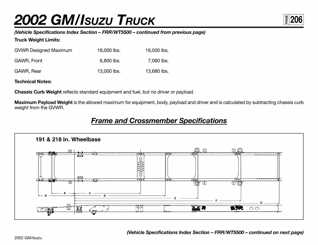
2002 GM/Isuzu
2002 GM/ISUZU TRUCK 206PA
GE
(Vehicle Specifications Index Section – FRR/WT5500 – continued from previous page)
Truck Weight Limits:
GVWR Designed Maximum 18,000 lbs. 19,500 lbs.
GAWR, Front 6,800 lbs. 7,060 lbs.
GAWR, Rear 13,000 lbs. 13,680 lbs.
Technical Notes:
Chassis Curb Weight reflects standard equipment and fuel, but no driver or payload.
Maximum Payload Weight is the allowed maximum for equipment, body, payload and driver and is calculated by subtracting chassis curbweight from the GVWR.
Frame and Crossmember Specifications
(Vehicle Specifications Index Section – FRR/WT5500 – continued on next page)
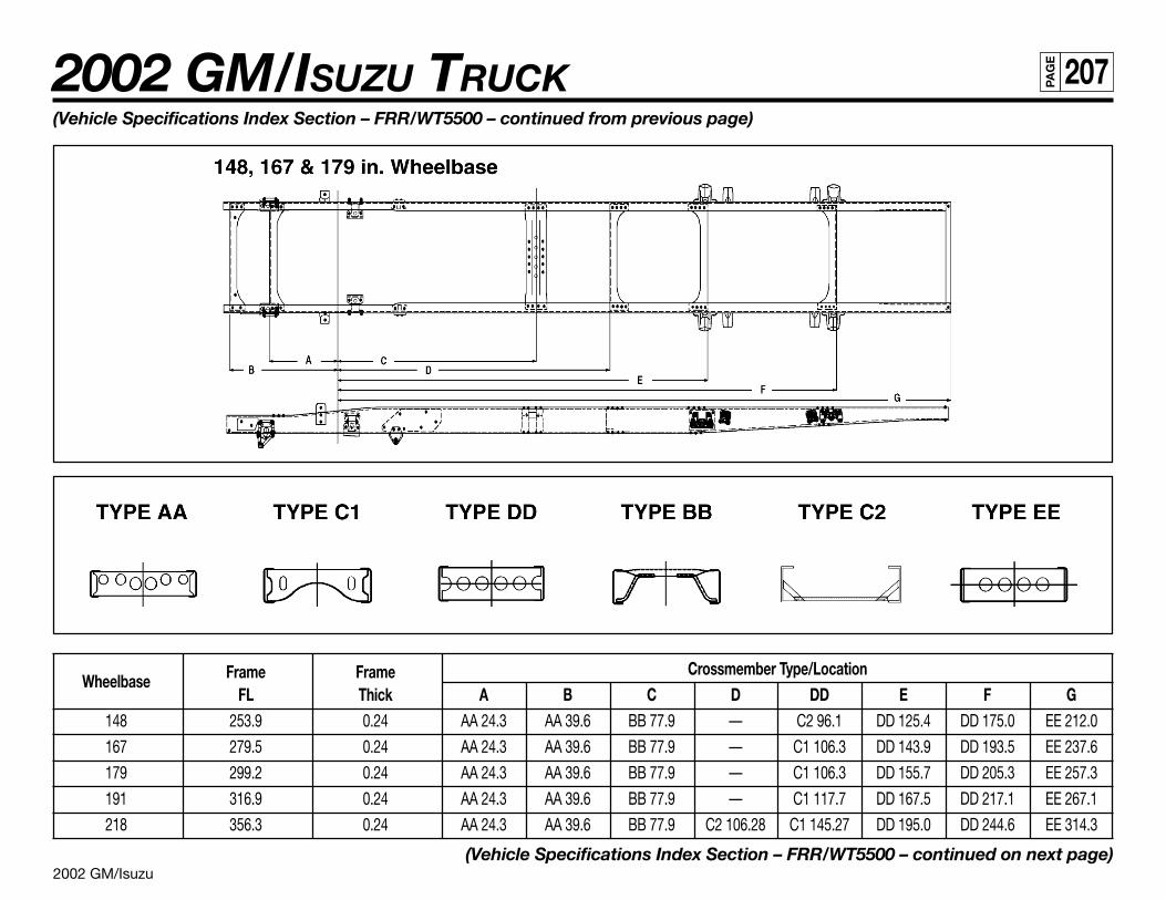
2002 GM/Isuzu
2002 GM/ISUZU TRUCK 207PA
GE
Wheelbase Frame Frame Crossmember Type/LocationFL Thick A B C D DD E F G
148 253.9 0.24 AA 24.3 AA 39.6 BB 77.9 — C2 96.1 DD 125.4 DD 175.0 EE 212.0
167 279.5 0.24 AA 24.3 AA 39.6 BB 77.9 — C1 106.3 DD 143.9 DD 193.5 EE 237.6
179 299.2 0.24 AA 24.3 AA 39.6 BB 77.9 — C1 106.3 DD 155.7 DD 205.3 EE 257.3
191 316.9 0.24 AA 24.3 AA 39.6 BB 77.9 — C1 117.7 DD 167.5 DD 217.1 EE 267.1
218 356.3 0.24 AA 24.3 AA 39.6 BB 77.9 C2 106.28 C1 145.27 DD 195.0 DD 244.6 EE 314.3
(Vehicle Specifications Index Section – FRR/WT5500 – continued on next page)
(Vehicle Specifications Index Section – FRR/WT5500 – continued from previous page)
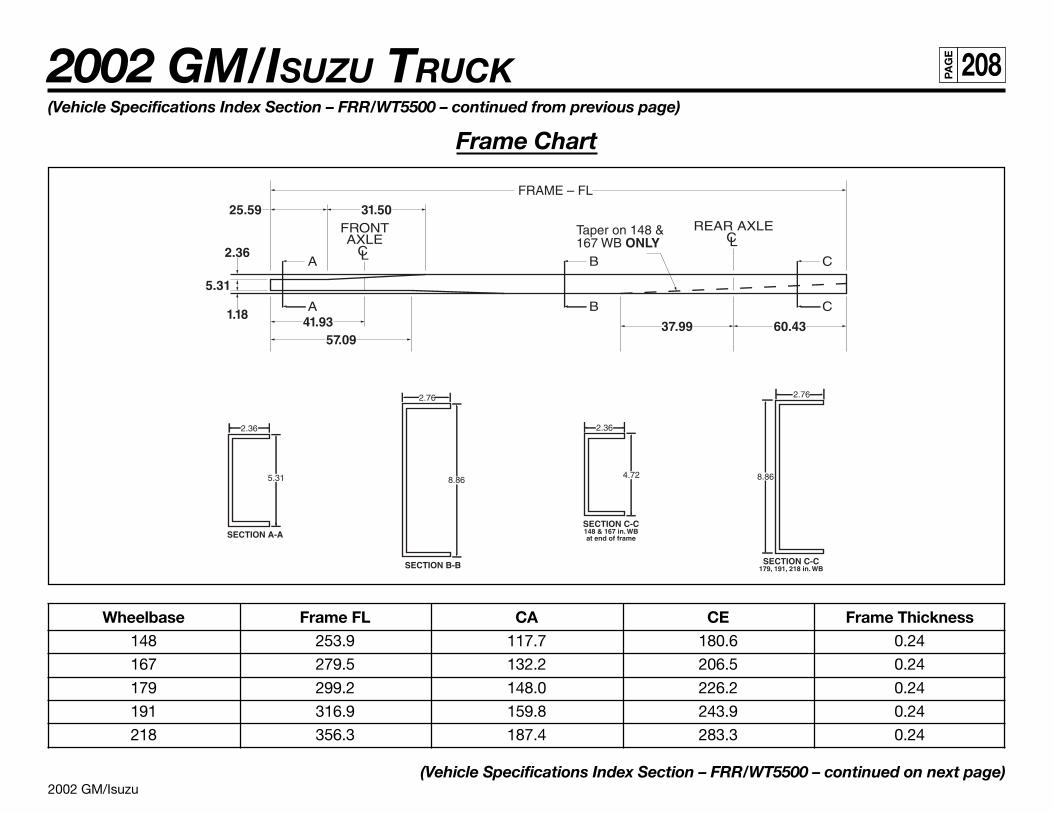
2002 GM/Isuzu
2002 GM/ISUZU TRUCK 208PA
GE
Wheelbase Frame FL CA CE Frame Thickness148 253.9 117.7 180.6 0.24
167 279.5 132.2 206.5 0.24
179 299.2 148.0 226.2 0.24
191 316.9 159.8 243.9 0.24
218 356.3 187.4 283.3 0.24
(Vehicle Specifications Index Section – FRR/WT5500 – continued on next page)
(Vehicle Specifications Index Section – FRR/WT5500 – continued from previous page)
Frame Chart
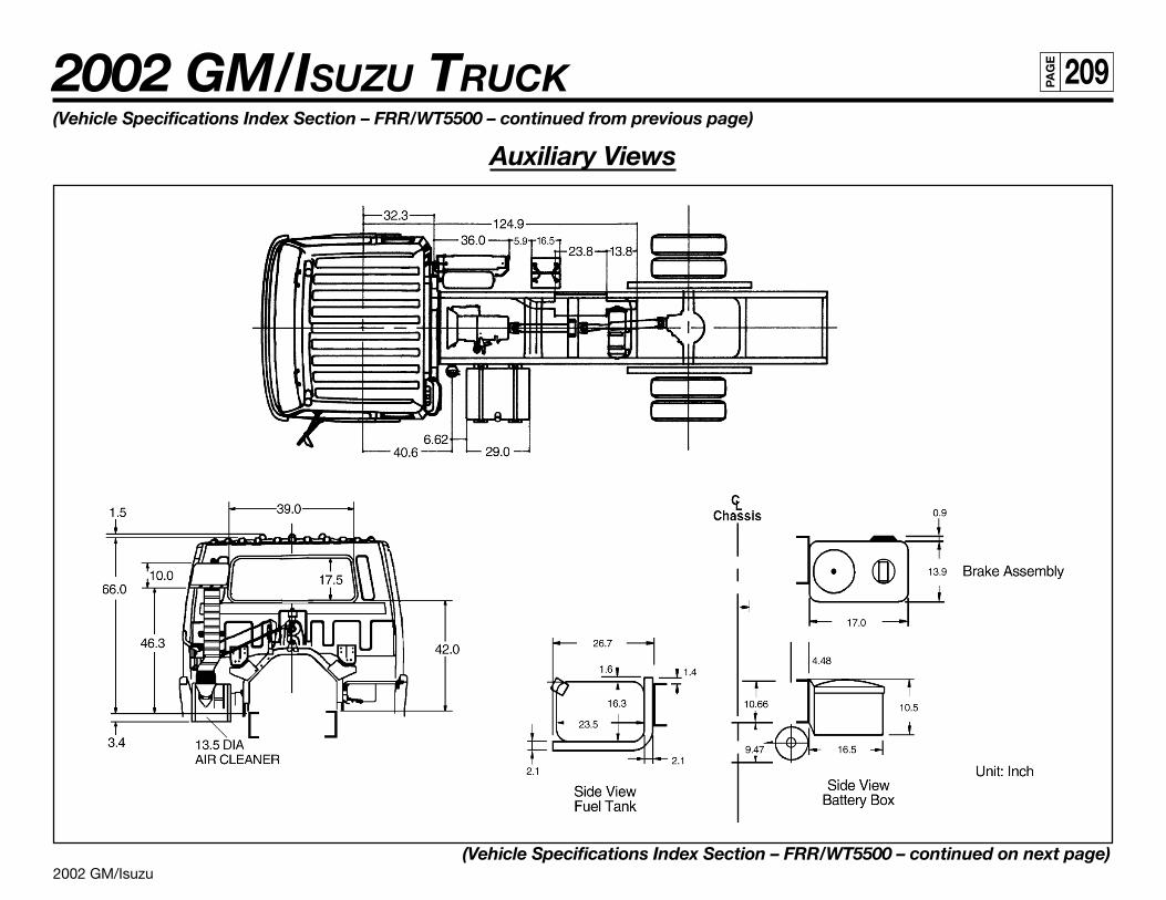
2002 GM/Isuzu
2002 GM/ISUZU TRUCK 209PA
GE
(Vehicle Specifications Index Section – FRR/WT5500 – continued from previous page)
Auxiliary Views
(Vehicle Specifications Index Section – FRR/WT5500 – continued on next page)
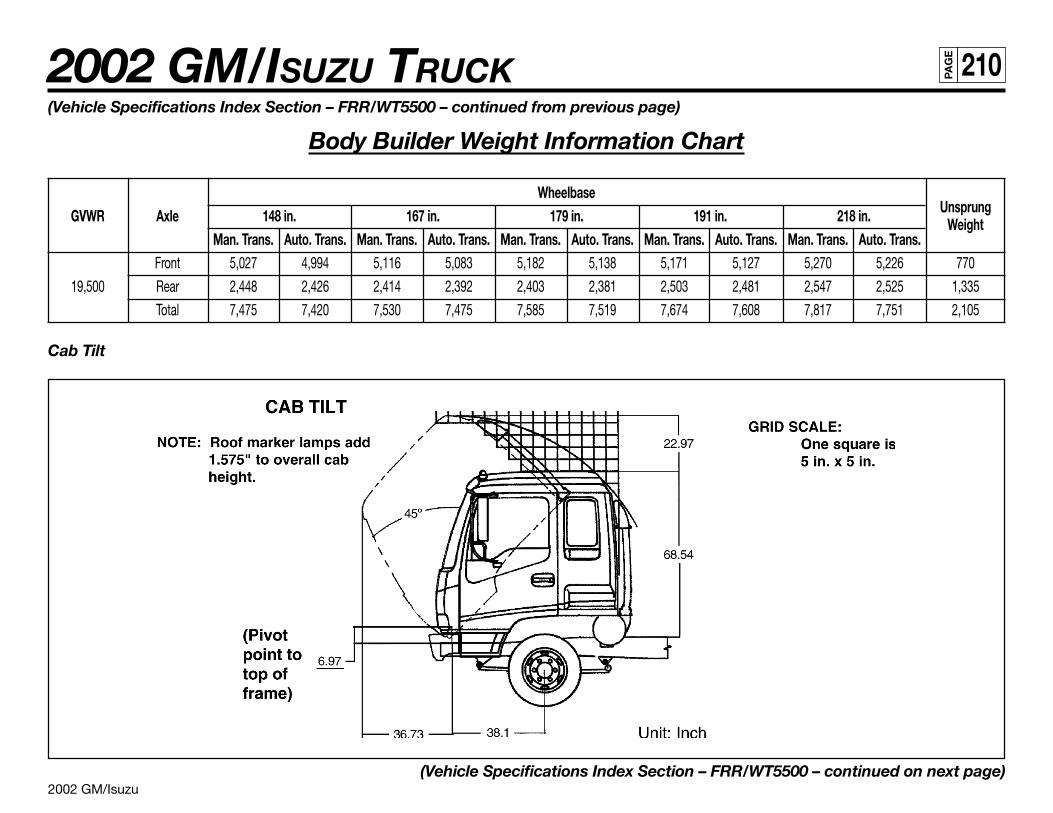
2002 GM/Isuzu
2002 GM/ISUZU TRUCK 210PA
GE
(Vehicle Specifications Index Section – FRR/WT5500 – continued from previous page)
Body Builder Weight Information Chart
WheelbaseUnsprungGVWR Axle 148 in. 167 in. 179 in. 191 in. 218 in. Weight
Man. Trans. Auto. Trans. Man. Trans. Auto. Trans. Man. Trans. Auto. Trans. Man. Trans. Auto. Trans. Man. Trans. Auto. Trans.Front 5,027 4,994 5,116 5,083 5,182 5,138 5,171 5,127 5,270 5,226 770
19,500 Rear 2,448 2,426 2,414 2,392 2,403 2,381 2,503 2,481 2,547 2,525 1,335
Total 7,475 7,420 7,530 7,475 7,585 7,519 7,674 7,608 7,817 7,751 2,105
Cab Tilt
(Vehicle Specifications Index Section – FRR/WT5500 – continued on next page)
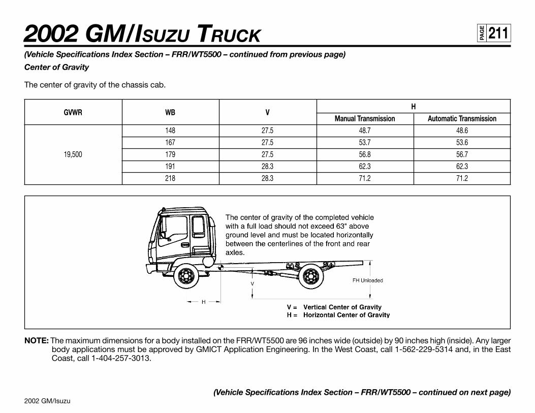
2002 GM/Isuzu
2002 GM/ISUZU TRUCK 211PA
GE
(Vehicle Specifications Index Section – FRR/WT5500 – continued from previous page)
Center of Gravity
The center of gravity of the chassis cab.
GVWR WB VH
Manual Transmission Automatic Transmission148 27.5 48.7 48.6
167 27.5 53.7 53.6
19,500 179 27.5 56.8 56.7
191 28.3 62.3 62.3
218 28.3 71.2 71.2
NOTE: The maximum dimensions for a body installed on the FRR/WT5500 are 96 inches wide (outside) by 90 inches high (inside). Any largerbody applications must be approved by GMICT Application Engineering. In the West Coast, call 1-562-229-5314 and, in the EastCoast, call 1-404-257-3013.
(Vehicle Specifications Index Section – FRR/WT5500 – continued on next page)
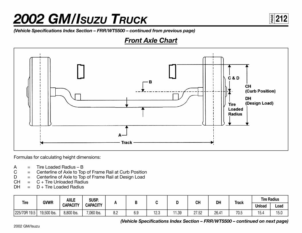
2002 GM/Isuzu
2002 GM/ISUZU TRUCK 212PA
GE
Formulas for calculating height dimensions:
A = Tire Loaded Radius – BC = Centerline of Axle to Top of Frame Rail at Curb PositionD = Centerline of Axle to Top of Frame Rail at Design LoadCH = C + Tire Unloaded RadiusDH = D + Tire Loaded Radius
Tire GVWR AXLE SUSP. A B C D CH DH TrackTire Radius
CAPACITY CAPACITY Unload Load225/70R 19.5 19,500 lbs. 8,800 lbs. 7,060 lbs. 8.2 6.9 12.3 11.39 27.52 26.41 70.5 15.4 15.0
(Vehicle Specifications Index Section – FRR/WT5500 – continued on next page)
(Vehicle Specifications Index Section – FRR/WT5500 – continued from previous page)
Front Axle Chart
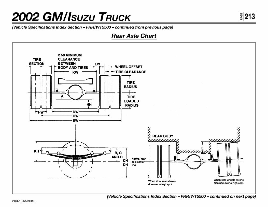
2002 GM/Isuzu
2002 GM/ISUZU TRUCK 213PA
GE
(Vehicle Specifications Index Section – FRR/WT5500 – continued from previous page)
Rear Axle Chart
(Vehicle Specifications Index Section – FRR/WT5500 – continued on next page)
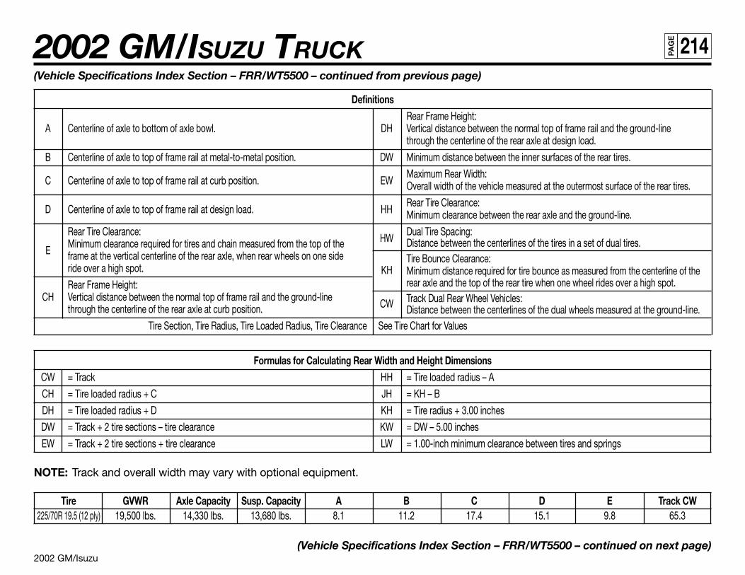
2002 GM/Isuzu
2002 GM/ISUZU TRUCK 214PA
GE
(Vehicle Specifications Index Section – FRR/WT5500 – continued from previous page)
DefinitionsRear Frame Height:
A Centerline of axle to bottom of axle bowl. DH Vertical distance between the normal top of frame rail and the ground-linethrough the centerline of the rear axle at design load.
B Centerline of axle to top of frame rail at metal-to-metal position. DW Minimum distance between the inner surfaces of the rear tires.
C Centerline of axle to top of frame rail at curb position. EWMaximum Rear Width:Overall width of the vehicle measured at the outermost surface of the rear tires.
D Centerline of axle to top of frame rail at design load. HHRear Tire Clearance:Minimum clearance between the rear axle and the ground-line.
Rear Tire Clearance:HW
Dual Tire Spacing:
EMinimum clearance required for tires and chain measured from the top of the Distance between the centerlines of the tires in a set of dual tires.frame at the vertical centerline of the rear axle, when rear wheels on one side Tire Bounce Clearance:ride over a high spot. KH Minimum distance required for tire bounce as measured from the centerline of theRear Frame Height: rear axle and the top of the rear tire when one wheel rides over a high spot.
CH Vertical distance between the normal top of frame rail and the ground-lineCW Track Dual Rear Wheel Vehicles:
through the centerline of the rear axle at curb position. Distance between the centerlines of the dual wheels measured at the ground-line.Tire Section, Tire Radius, Tire Loaded Radius, Tire Clearance See Tire Chart for Values
Formulas for Calculating Rear Width and Height DimensionsCW = Track HH = Tire loaded radius – A
CH = Tire loaded radius + C JH = KH – B
DH = Tire loaded radius + D KH = Tire radius + 3.00 inches
DW = Track + 2 tire sections – tire clearance KW = DW – 5.00 inches
EW = Track + 2 tire sections + tire clearance LW = 1.00-inch minimum clearance between tires and springs
NOTE: Track and overall width may vary with optional equipment.
Tire GVWR Axle Capacity Susp. Capacity A B C D E Track CW225/70R 19.5 (12 ply) 19,500 lbs. 14,330 lbs. 13,680 lbs. 8.1 11.2 17.4 15.1 9.8 65.3
(Vehicle Specifications Index Section – FRR/WT5500 – continued on next page)
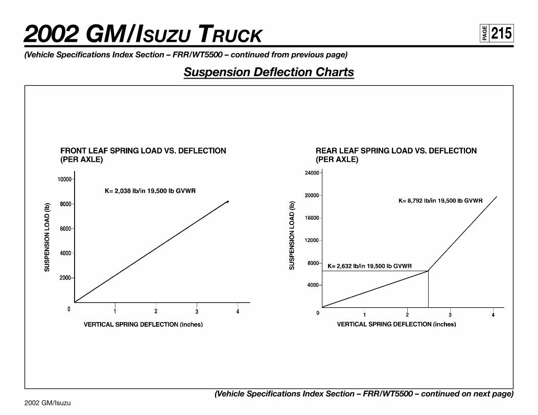
2002 GM/Isuzu
2002 GM/ISUZU TRUCK 215PA
GE
(Vehicle Specifications Index Section – FRR/WT5500 – continued from previous page)
Suspension Deflection Charts
(Vehicle Specifications Index Section – FRR/WT5500 – continued on next page)
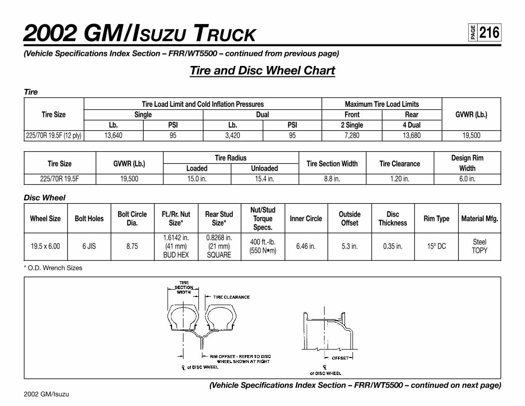
2002 GM/Isuzu
2002 GM/ISUZU TRUCK 216PA
GE
(Vehicle Specifications Index Section – FRR/WT5500 – continued from previous page)
Tire and Disc Wheel Chart
Tire
Tire Load Limit and Cold Inflation Pressures Maximum Tire Load LimitsTire Size Single Dual Front Rear GVWR (Lb.)
Lb. PSI Lb. PSI 2 Single 4 Dual225/70R 19.5F (12 ply) 13,640 95 3,420 95 7,280 13,680 19,500
Tire Size GVWR (Lb.)Tire Radius
Tire Section Width Tire ClearanceDesign Rim
Loaded Unloaded Width225/70R 19.5F 19,500 15.0 in. 15.4 in. 8.8 in. 1.20 in. 6.0 in.
Disc Wheel
Bolt Circle Ft./Rr. Nut Rear Stud Nut/Stud Outside DiscWheel Size Bolt Holes Dia. Size* Size* Torque Inner Circle Offset Thickness Rim Type Material Mfg.Specs.
1.6142 in. 0.8268 in. 400 ft.-lb. Steel19.5 x 6.00 6 JIS 8.75 (41 mm) (21 mm) (550 N•m) 6.46 in. 5.3 in. 0.35 in. 15º DC TOPYBUD HEX SQUARE
* O.D. Wrench Sizes
(Vehicle Specifications Index Section – FRR/WT5500 – continued on next page)
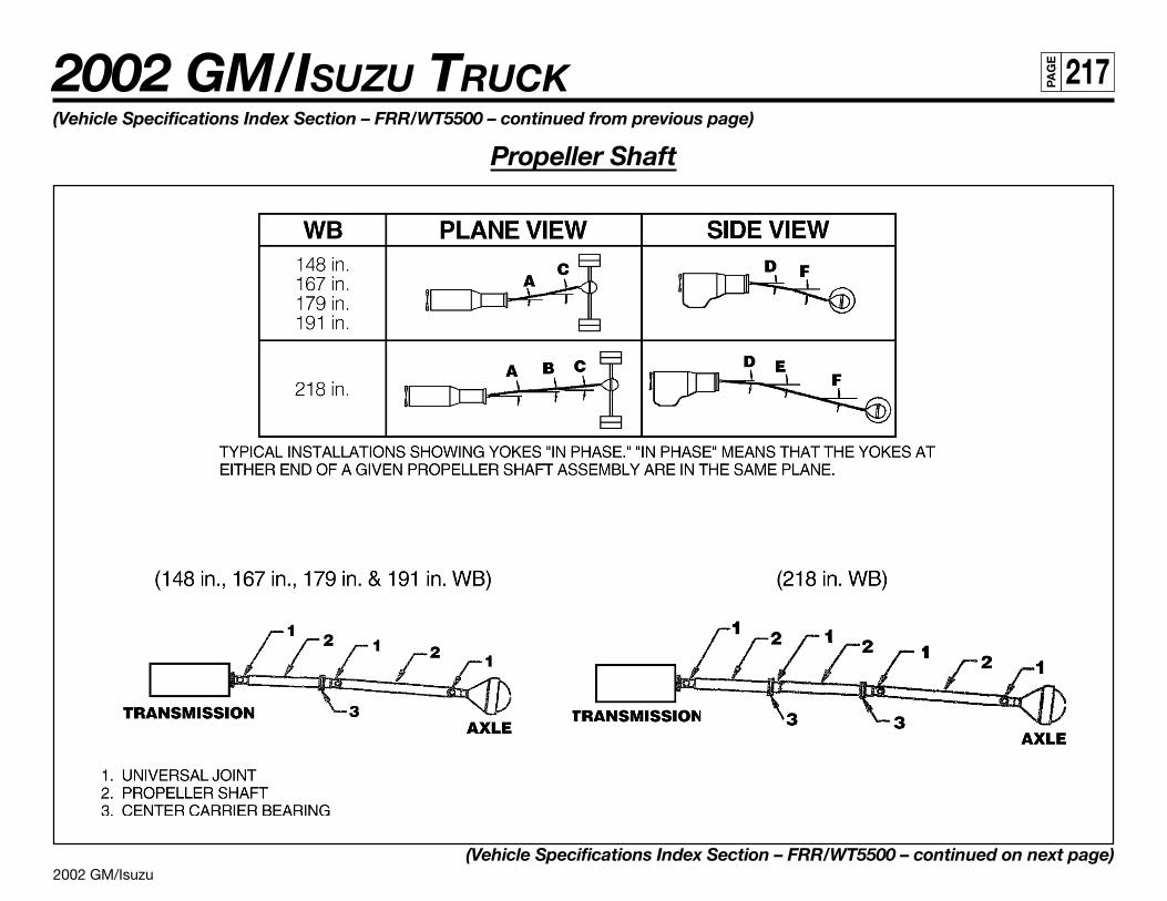
2002 GM/Isuzu
2002 GM/ISUZU TRUCK 217PA
GE
(Vehicle Specifications Index Section – FRR/WT5500 – continued from previous page)
Propeller Shaft
(Vehicle Specifications Index Section – FRR/WT5500 – continued on next page)
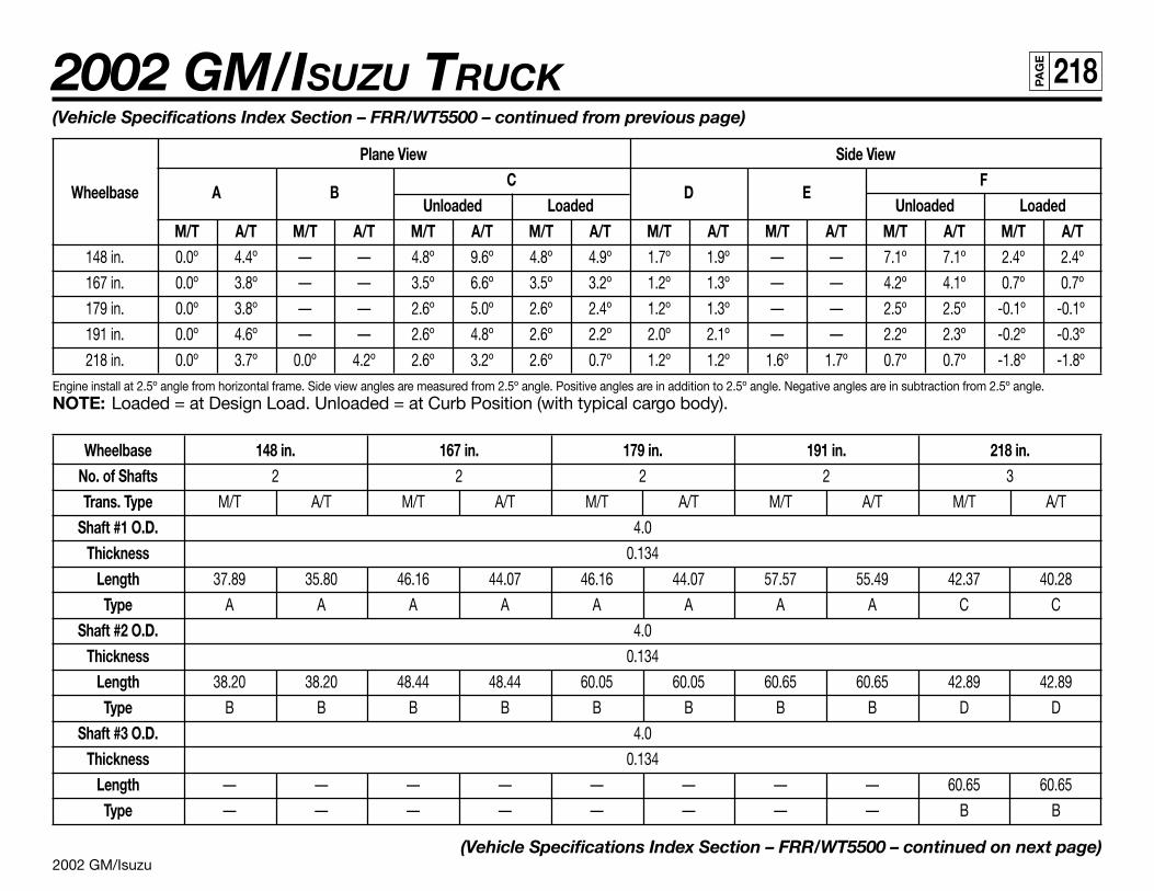
2002 GM/Isuzu
2002 GM/ISUZU TRUCK 218PA
GE
(Vehicle Specifications Index Section – FRR/WT5500 – continued from previous page)
Plane View Side View
Wheelbase A BC
D EF
Unloaded Loaded Unloaded LoadedM/T A/T M/T A/T M/T A/T M/T A/T M/T A/T M/T A/T M/T A/T M/T A/T
148 in. 0.0º 4.4º — — 4.8º 9.6º 4.8º 4.9º 1.7º 1.9º — — 7.1º 7.1º 2.4º 2.4º
167 in. 0.0º 3.8º — — 3.5º 6.6º 3.5º 3.2º 1.2º 1.3º — — 4.2º 4.1º 0.7º 0.7º
179 in. 0.0º 3.8º — — 2.6º 5.0º 2.6º 2.4º 1.2º 1.3º — — 2.5º 2.5º -0.1º -0.1º
191 in. 0.0º 4.6º — — 2.6º 4.8º 2.6º 2.2º 2.0º 2.1º — — 2.2º 2.3º -0.2º -0.3º
218 in. 0.0º 3.7º 0.0º 4.2º 2.6º 3.2º 2.6º 0.7º 1.2º 1.2º 1.6º 1.7º 0.7º 0.7º -1.8º -1.8ºEngine install at 2.5º angle from horizontal frame. Side view angles are measured from 2.5º angle. Positive angles are in addition to 2.5º angle. Negative angles are in subtraction from 2.5º angle.NOTE: Loaded = at Design Load. Unloaded = at Curb Position (with typical cargo body).
Wheelbase 148 in. 167 in. 179 in. 191 in. 218 in.No. of Shafts 2 2 2 2 3
Trans. Type M/T A/T M/T A/T M/T A/T M/T A/T M/T A/T
Shaft #1 O.D. 4.0
Thickness 0.134
Length 37.89 35.80 46.16 44.07 46.16 44.07 57.57 55.49 42.37 40.28
Type A A A A A A A A C C
Shaft #2 O.D. 4.0
Thickness 0.134
Length 38.20 38.20 48.44 48.44 60.05 60.05 60.65 60.65 42.89 42.89
Type B B B B B B B B D D
Shaft #3 O.D. 4.0
Thickness 0.134
Length — — — — — — — — 60.65 60.65
Type — — — — — — — — B B
(Vehicle Specifications Index Section – FRR/WT5500 – continued on next page)
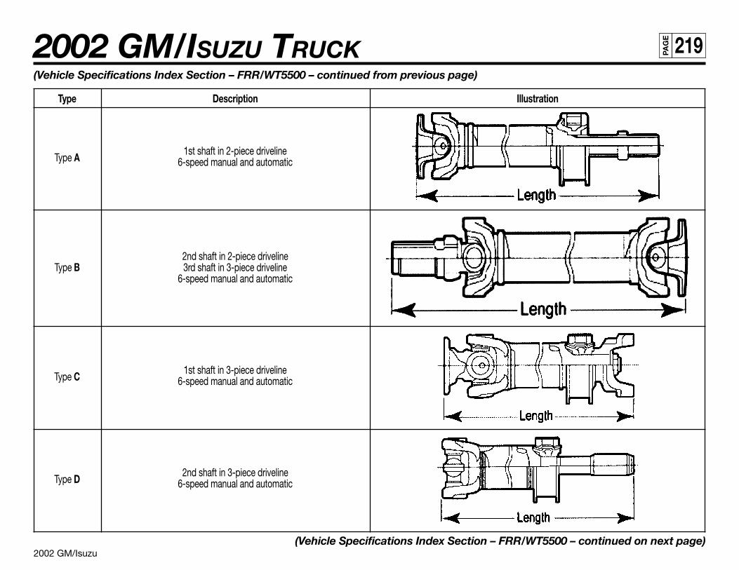
2002 GM/Isuzu
2002 GM/ISUZU TRUCK 219PA
GE
(Vehicle Specifications Index Section – FRR/WT5500 – continued from previous page)
Type Description Illustration
Type A1st shaft in 2-piece driveline
6-speed manual and automatic
2nd shaft in 2-piece drivelineType B 3rd shaft in 3-piece driveline
6-speed manual and automatic
Type C1st shaft in 3-piece driveline
6-speed manual and automatic
Type D2nd shaft in 3-piece driveline
6-speed manual and automatic
(Vehicle Specifications Index Section – FRR/WT5500 – continued on next page)
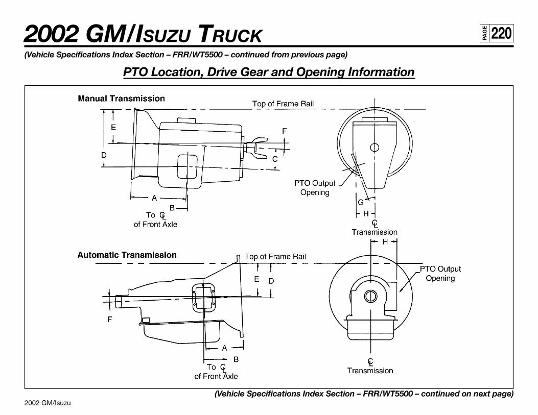
2002 GM/Isuzu
2002 GM/ISUZU TRUCK 220PA
GE
(Vehicle Specifications Index Section – FRR/WT5500 – continued from previous page)
PTO Location, Drive Gear and Opening Information
(Vehicle Specifications Index Section – FRR/WT5500 – continued on next page)
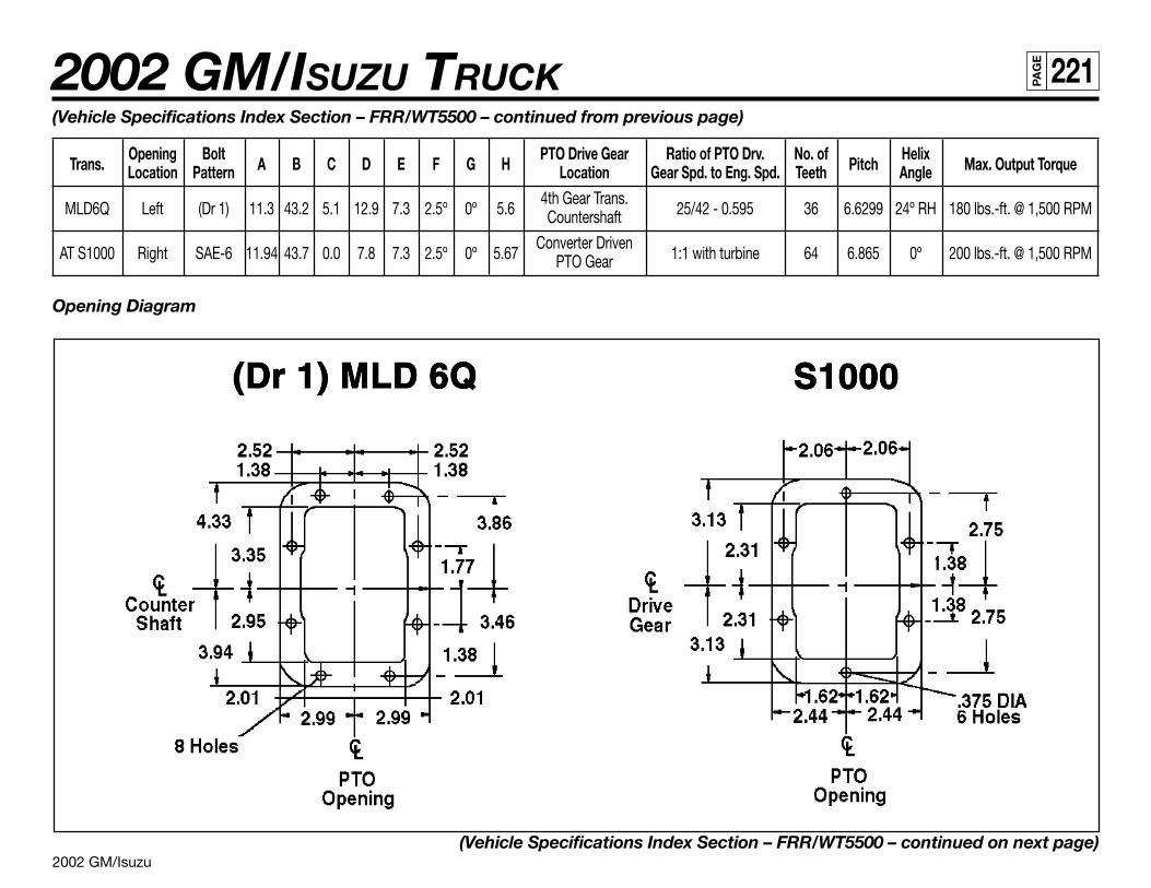
2002 GM/Isuzu
2002 GM/ISUZU TRUCK 221PA
GE
(Vehicle Specifications Index Section – FRR/WT5500 – continued from previous page)
Trans.Opening Bolt
A B C D E F G HPTO Drive Gear Ratio of PTO Drv. No. of
PitchHelix
Max. Output TorqueLocation Pattern Location Gear Spd. to Eng. Spd. Teeth Angle
MLD6Q Left (Dr 1) 11.3 43.2 5.1 12.9 7.3 2.5º 0º 5.64th Gear Trans.
25/42 - 0.595 36 6.6299 24º RH 180 lbs.-ft. @ 1,500 RPMCountershaft
AT S1000 Right SAE-6 11.94 43.7 0.0 7.8 7.3 2.5º 0º 5.67Converter Driven
1:1 with turbine 64 6.865 0º 200 lbs.-ft. @ 1,500 RPMPTO Gear
Opening Diagram
(Vehicle Specifications Index Section – FRR/WT5500 – continued on next page)
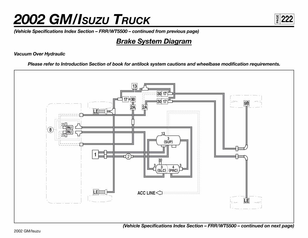
2002 GM/Isuzu
2002 GM/ISUZU TRUCK 222PA
GE
(Vehicle Specifications Index Section – FRR/WT5500 – continued from previous page)
Brake System Diagram
Vacuum Over Hydraulic
Please refer to Introduction Section of book for antilock system cautions and wheelbase modification requirements.
(Vehicle Specifications Index Section – FRR/WT5500 – continued on next page)
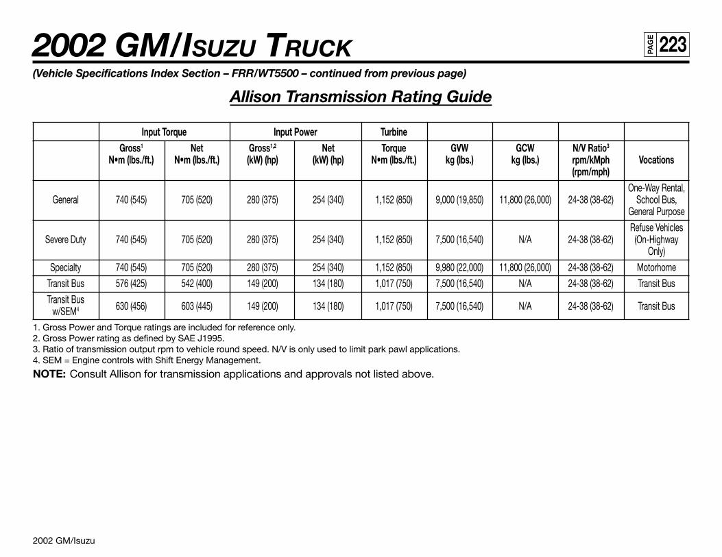
2002 GM/Isuzu
2002 GM/ISUZU TRUCK 223PA
GE
(Vehicle Specifications Index Section – FRR/WT5500 – continued from previous page)
Allison Transmission Rating Guide
Input Torque Input Power TurbineGross1 Net Gross1,2 Net Torque GVW GCW N/V Ratio3
N•m (lbs./ft.) N•m (lbs./ft.) (kW) (hp) (kW) (hp) N•m (lbs./ft.) kg (lbs.) kg (lbs.) rpm/kMph Vocations(rpm/mph)
One-Way Rental,General 740 (545) 705 (520) 280 (375) 254 (340) 1,152 (850) 9,000 (19,850) 11,800 (26,000) 24-38 (38-62) School Bus,
General Purpose
Refuse VehiclesSevere Duty 740 (545) 705 (520) 280 (375) 254 (340) 1,152 (850) 7,500 (16,540) N/A 24-38 (38-62) (On-Highway
Only)
Specialty 740 (545) 705 (520) 280 (375) 254 (340) 1,152 (850) 9,980 (22,000) 11,800 (26,000) 24-38 (38-62) Motorhome
Transit Bus 576 (425) 542 (400) 149 (200) 134 (180) 1,017 (750) 7,500 (16,540) N/A 24-38 (38-62) Transit Bus
Transit Bus630 (456) 603 (445) 149 (200) 134 (180) 1,017 (750) 7,500 (16,540) N/A 24-38 (38-62) Transit Busw/SEM4
1. Gross Power and Torque ratings are included for reference only.2. Gross Power rating as defined by SAE J1995.3. Ratio of transmission output rpm to vehicle round speed. N/V is only used to limit park pawl applications.4. SEM = Engine controls with Shift Energy Management.
NOTE: Consult Allison for transmission applications and approvals not listed above.
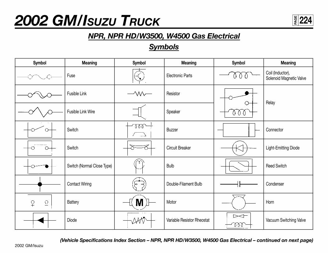
2002 GM/Isuzu
2002 GM/ISUZU TRUCK 224PA
GE
NPR, NPR HD/W3500, W4500 Gas ElectricalSymbols
Symbol Meaning Symbol Meaning Symbol Meaning
Fuse Electronic Parts Coil (Inductor),Solenoid Magnetic Valve
Fusible Link Resistor
Relay
Fusible Link Wire Speaker
Switch Buzzer Connector
Switch Circuit Breaker Light-Emitting Diode
Switch (Normal Close Type) Bulb Reed Switch
Contact Wiring Double-Filament Bulb Condenser
Battery Motor Horn
Diode Variable Resistor Rheostat Vacuum Switching Valve
(Vehicle Specifications Index Section – NPR, NPR HD/W3500, W4500 Gas Electrical – continued on next page)
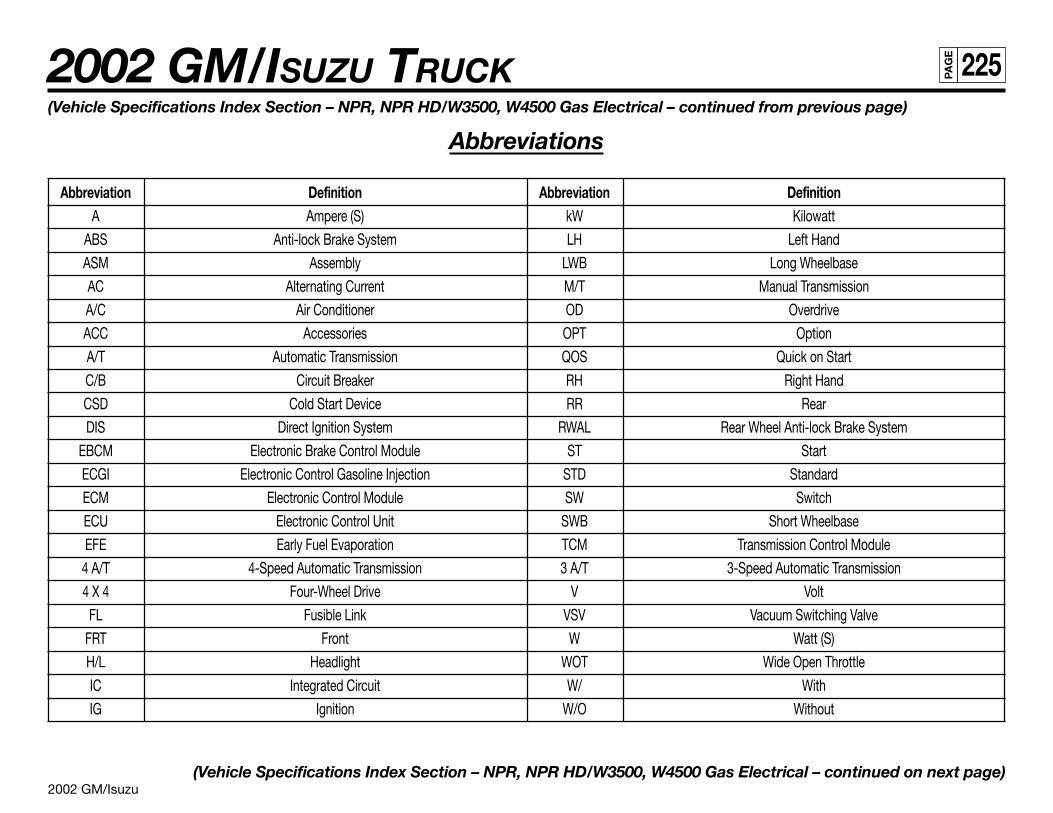
2002 GM/Isuzu
2002 GM/ISUZU TRUCK 225PA
GE
(Vehicle Specifications Index Section – NPR, NPR HD/W3500, W4500 Gas Electrical – continued from previous page)
Abbreviations
Abbreviation Definition Abbreviation DefinitionA Ampere (S) kW Kilowatt
ABS Anti-lock Brake System LH Left Hand
ASM Assembly LWB Long Wheelbase
AC Alternating Current M/T Manual Transmission
A/C Air Conditioner OD Overdrive
ACC Accessories OPT Option
A/T Automatic Transmission QOS Quick on Start
C/B Circuit Breaker RH Right Hand
CSD Cold Start Device RR Rear
DIS Direct Ignition System RWAL Rear Wheel Anti-lock Brake System
EBCM Electronic Brake Control Module ST Start
ECGI Electronic Control Gasoline Injection STD Standard
ECM Electronic Control Module SW Switch
ECU Electronic Control Unit SWB Short Wheelbase
EFE Early Fuel Evaporation TCM Transmission Control Module
4 A/T 4-Speed Automatic Transmission 3 A/T 3-Speed Automatic Transmission
4 X 4 Four-Wheel Drive V Volt
FL Fusible Link VSV Vacuum Switching Valve
FRT Front W Watt (S)
H/L Headlight WOT Wide Open Throttle
IC Integrated Circuit W/ With
IG Ignition W/O Without
(Vehicle Specifications Index Section – NPR, NPR HD/W3500, W4500 Gas Electrical – continued on next page)
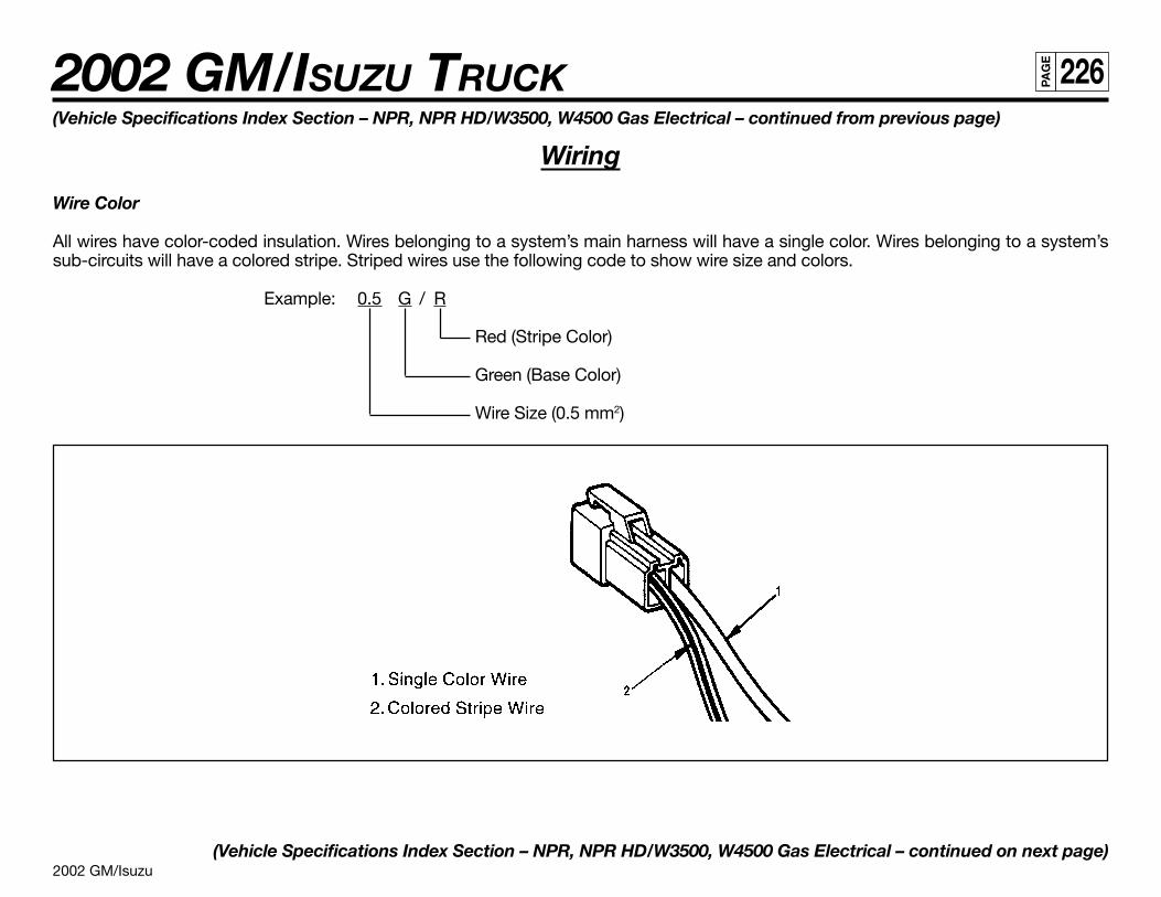
2002 GM/Isuzu
2002 GM/ISUZU TRUCK 226PA
GE
(Vehicle Specifications Index Section – NPR, NPR HD/W3500, W4500 Gas Electrical – continued from previous page)
Wiring
Wire Color
All wires have color-coded insulation. Wires belonging to a system’s main harness will have a single color. Wires belonging to a system’ssub-circuits will have a colored stripe. Striped wires use the following code to show wire size and colors.
Example: 0.5 G / R
Red (Stripe Color)
Green (Base Color)
Wire Size (0.5 mm2)
(Vehicle Specifications Index Section – NPR, NPR HD/W3500, W4500 Gas Electrical – continued on next page)
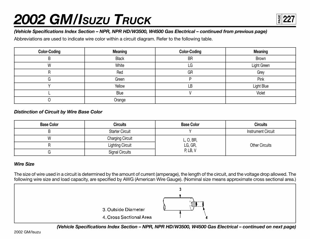
2002 GM/Isuzu
2002 GM/ISUZU TRUCK 227PA
GE
(Vehicle Specifications Index Section – NPR, NPR HD/W3500, W4500 Gas Electrical – continued from previous page)
Abbreviations are used to indicate wire color within a circuit diagram. Refer to the following table.
Color-Coding Meaning Color-Coding MeaningB Black BR Brown
W White LG Light Green
R Red GR Grey
G Green P Pink
Y Yellow LB Light Blue
L Blue V Violet
O Orange
Distinction of Circuit by Wire Base Color
Base Color Circuits Base Color CircuitsB Starter Circuit Y Instrument Circuit
W Charging Circuit L, O, BR,R Lighting Circuit LG, GR, Other Circuits
G Signal Circuits P, LB, V
Wire Size
The size of wire used in a circuit is determined by the amount of current (amperage), the length of the circuit, and the voltage drop allowed. Thefollowing wire size and load capacity, are specified by AWG (American Wire Gauge). (Nominal size means approximate cross sectional area.)
(Vehicle Specifications Index Section – NPR, NPR HD/W3500, W4500 Gas Electrical – continued on next page)
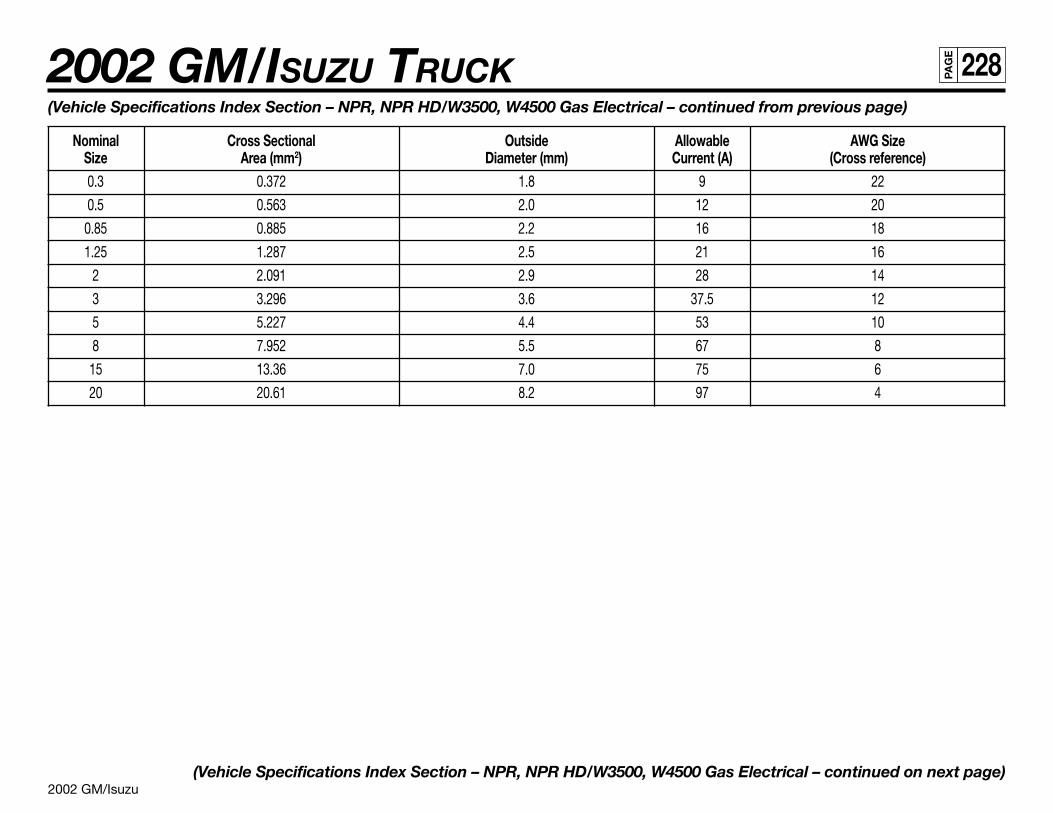
2002 GM/Isuzu
2002 GM/ISUZU TRUCK 228PA
GE
(Vehicle Specifications Index Section – NPR, NPR HD/W3500, W4500 Gas Electrical – continued from previous page)
Nominal Cross Sectional Outside Allowable AWG SizeSize Area (mm2) Diameter (mm) Current (A) (Cross reference)0.3 0.372 1.8 9 22
0.5 0.563 2.0 12 20
0.85 0.885 2.2 16 18
1.25 1.287 2.5 21 16
2 2.091 2.9 28 14
3 3.296 3.6 37.5 12
5 5.227 4.4 53 10
8 7.952 5.5 67 8
15 13.36 7.0 75 6
20 20.61 8.2 97 4
(Vehicle Specifications Index Section – NPR, NPR HD/W3500, W4500 Gas Electrical – continued on next page)
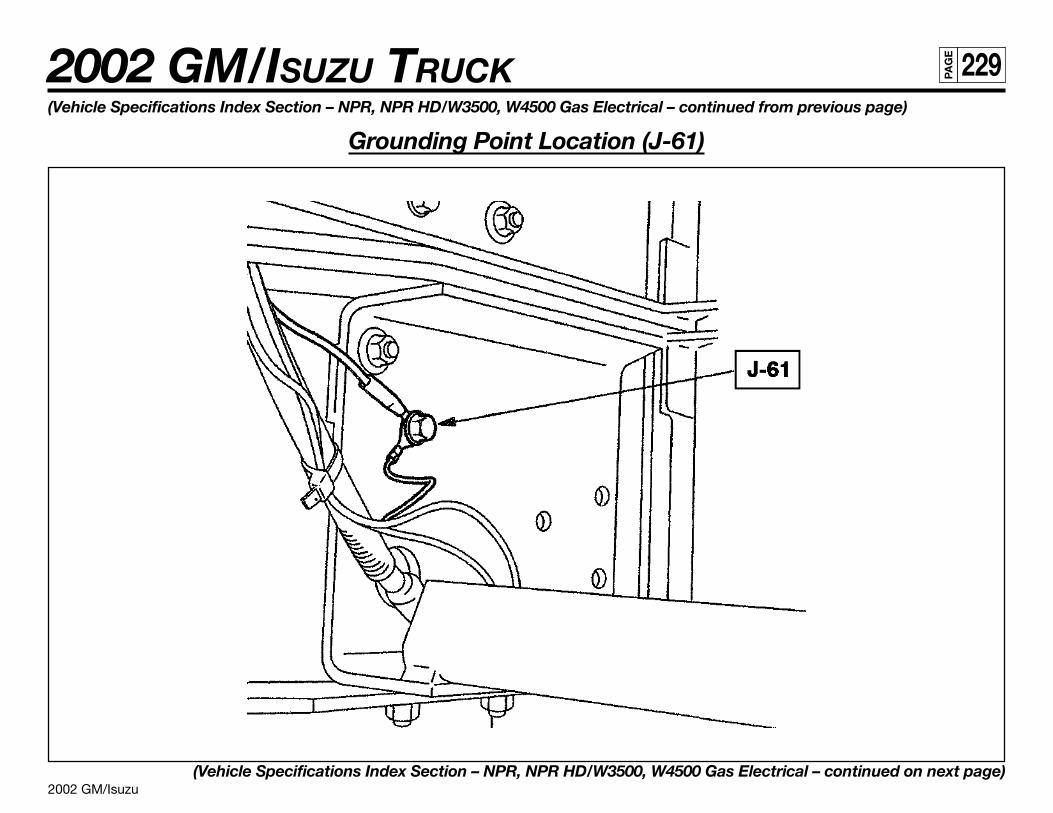
2002 GM/Isuzu
2002 GM/ISUZU TRUCK 229PA
GE
(Vehicle Specifications Index Section – NPR, NPR HD/W3500, W4500 Gas Electrical – continued from previous page)
Grounding Point Location (J-61)
(Vehicle Specifications Index Section – NPR, NPR HD/W3500, W4500 Gas Electrical – continued on next page)
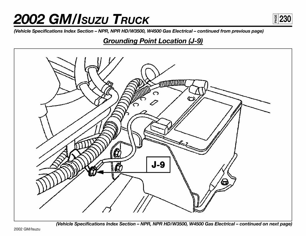
2002 GM/Isuzu
2002 GM/ISUZU TRUCK 230PA
GE
(Vehicle Specifications Index Section – NPR, NPR HD/W3500, W4500 Gas Electrical – continued from previous page)
Grounding Point Location (J-9)
(Vehicle Specifications Index Section – NPR, NPR HD/W3500, W4500 Gas Electrical – continued on next page)
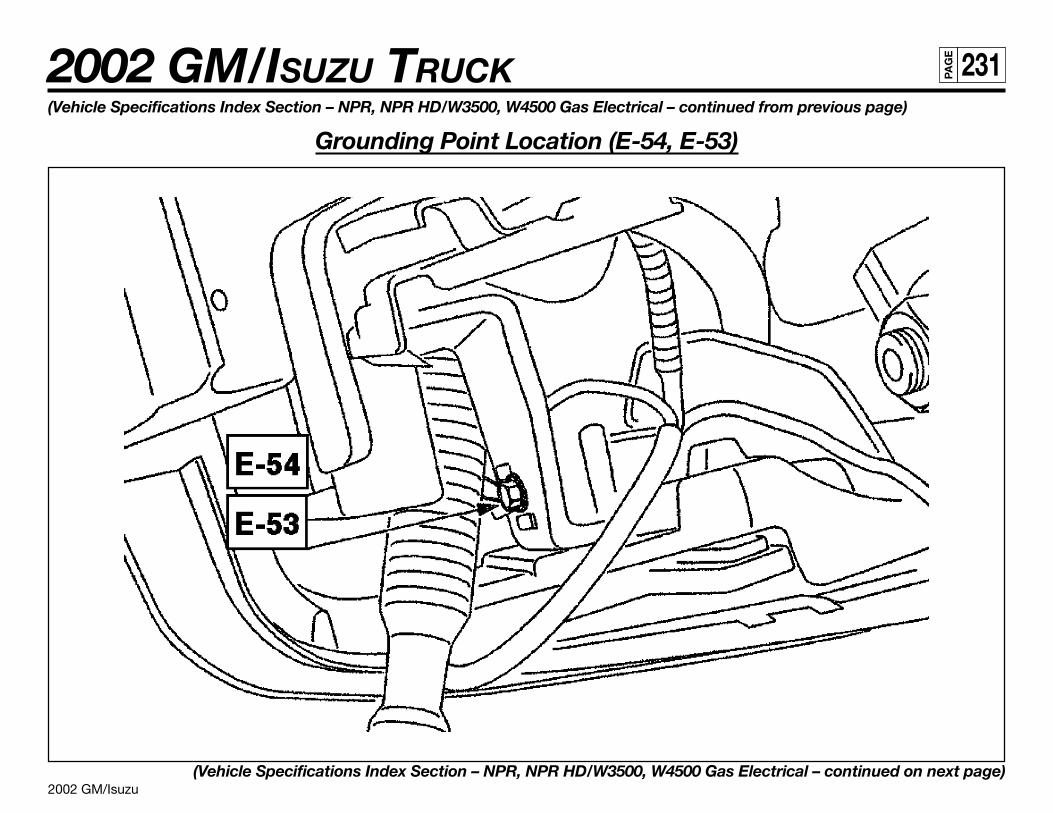
2002 GM/Isuzu
2002 GM/ISUZU TRUCK 231PA
GE
(Vehicle Specifications Index Section – NPR, NPR HD/W3500, W4500 Gas Electrical – continued from previous page)
Grounding Point Location (E-54, E-53)
(Vehicle Specifications Index Section – NPR, NPR HD/W3500, W4500 Gas Electrical – continued on next page)
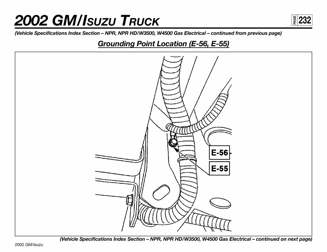
2002 GM/Isuzu
2002 GM/ISUZU TRUCK 232PA
GE
(Vehicle Specifications Index Section – NPR, NPR HD/W3500, W4500 Gas Electrical – continued from previous page)
Grounding Point Location (E-56, E-55)
(Vehicle Specifications Index Section – NPR, NPR HD/W3500, W4500 Gas Electrical – continued on next page)
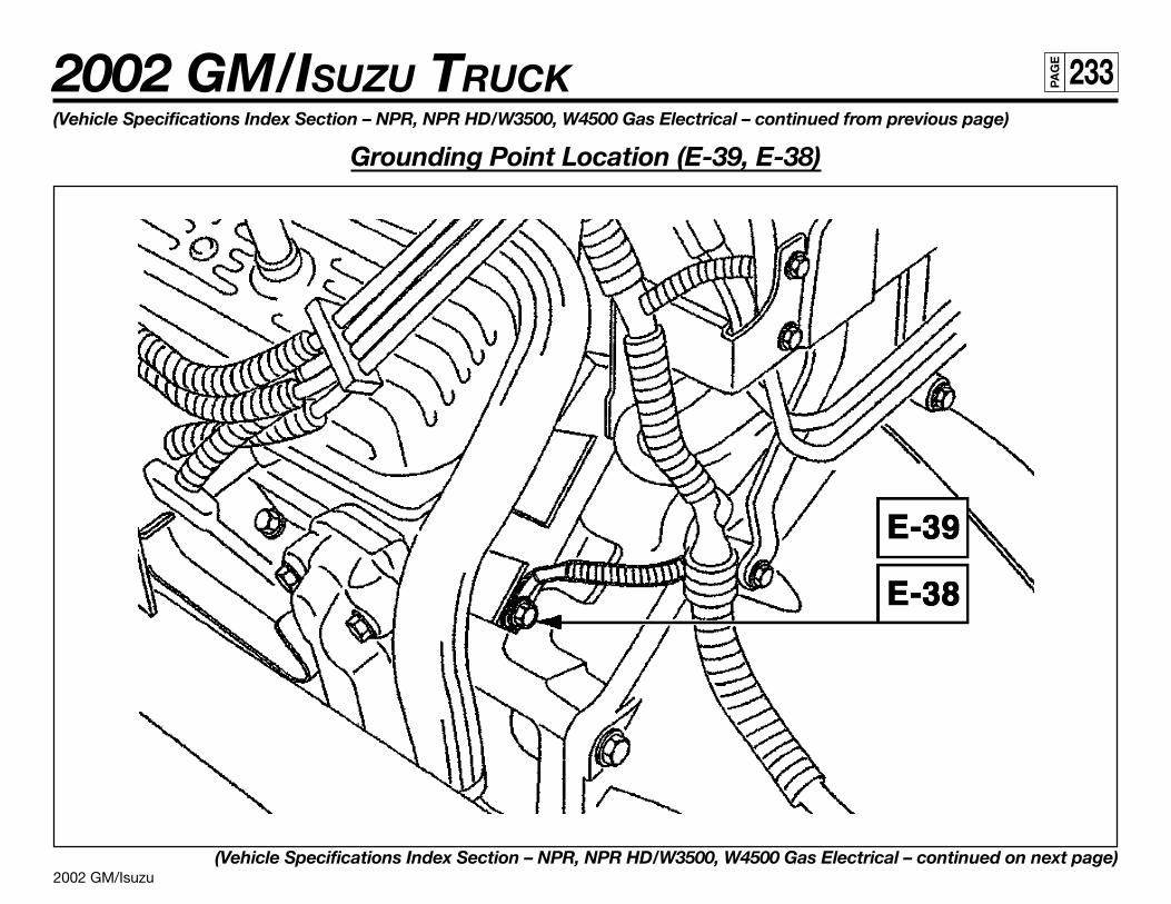
2002 GM/Isuzu
2002 GM/ISUZU TRUCK 233PA
GE
(Vehicle Specifications Index Section – NPR, NPR HD/W3500, W4500 Gas Electrical – continued from previous page)
Grounding Point Location (E-39, E-38)
(Vehicle Specifications Index Section – NPR, NPR HD/W3500, W4500 Gas Electrical – continued on next page)
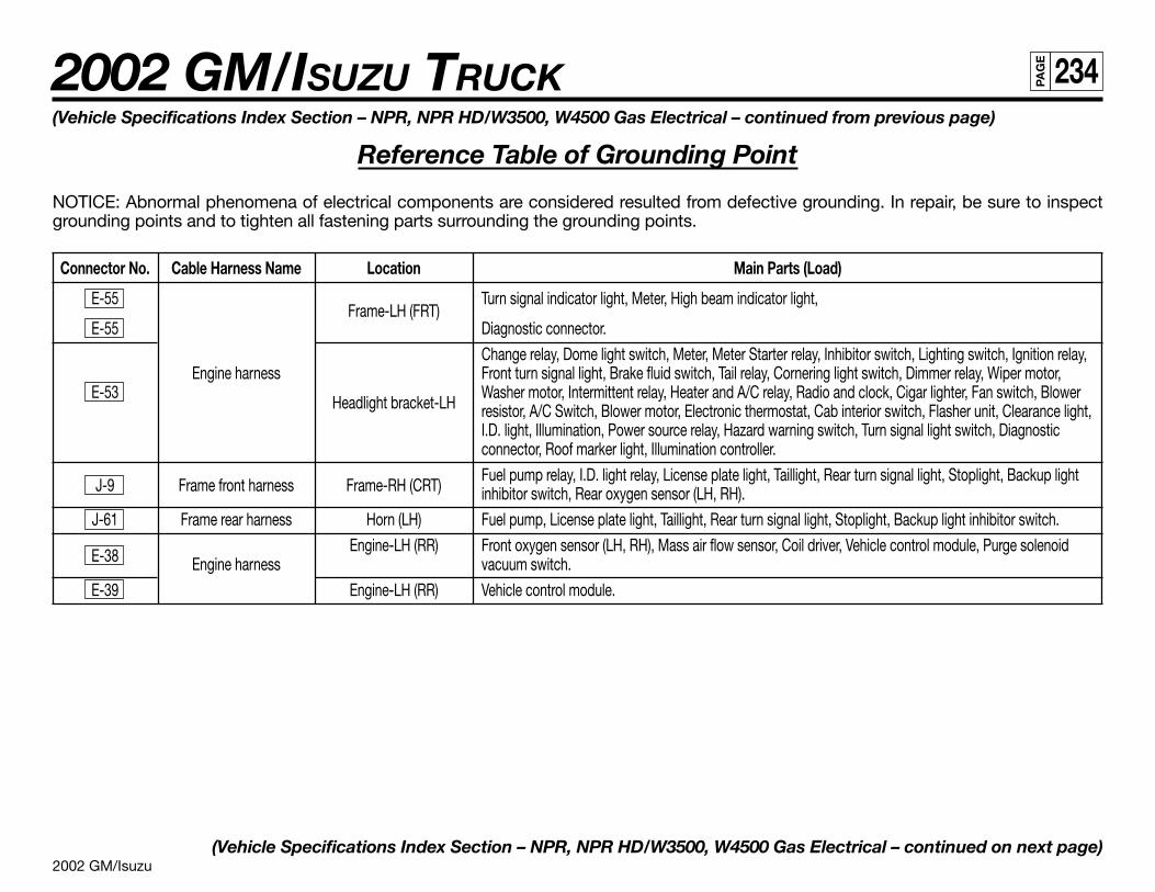
2002 GM/Isuzu
2002 GM/ISUZU TRUCK 234PA
GE
(Vehicle Specifications Index Section – NPR, NPR HD/W3500, W4500 Gas Electrical – continued from previous page)
Reference Table of Grounding Point
NOTICE: Abnormal phenomena of electrical components are considered resulted from defective grounding. In repair, be sure to inspectgrounding points and to tighten all fastening parts surrounding the grounding points.
Connector No. Cable Harness Name Location Main Parts (Load)
E-55Frame-LH (FRT)
Turn signal indicator light, Meter, High beam indicator light,
E-55 Diagnostic connector.
Change relay, Dome light switch, Meter, Meter Starter relay, Inhibitor switch, Lighting switch, Ignition relay,Engine harness Front turn signal light, Brake fluid switch, Tail relay, Cornering light switch, Dimmer relay, Wiper motor,
E-53Headlight bracket-LH
Washer motor, Intermittent relay, Heater and A/C relay, Radio and clock, Cigar lighter, Fan switch, Blowerresistor, A/C Switch, Blower motor, Electronic thermostat, Cab interior switch, Flasher unit, Clearance light,I.D. light, Illumination, Power source relay, Hazard warning switch, Turn signal light switch, Diagnosticconnector, Roof marker light, Illumination controller.
J-9 Frame front harness Frame-RH (CRT)Fuel pump relay, I.D. light relay, License plate light, Taillight, Rear turn signal light, Stoplight, Backup lightinhibitor switch, Rear oxygen sensor (LH, RH).
J-61 Frame rear harness Horn (LH) Fuel pump, License plate light, Taillight, Rear turn signal light, Stoplight, Backup light inhibitor switch.
E-38Engine-LH (RR) Front oxygen sensor (LH, RH), Mass air flow sensor, Coil driver, Vehicle control module, Purge solenoid
Engine harness vacuum switch.
E-39 Engine-LH (RR) Vehicle control module.
(Vehicle Specifications Index Section – NPR, NPR HD/W3500, W4500 Gas Electrical – continued on next page)

2002 GM/Isuzu
2002 GM/ISUZU TRUCK 235PA
GE
(Vehicle Specifications Index Section – NPR, NPR HD/W3500, W4500 Gas Electrical – continued from previous page)
NPR/W3500 Body Room Light, I.D. and Marker Lamp,and Back-Up Lamp Connector Location
(Vehicle Specifications Index Section – NPR, NPR HD/W3500, W4500 Gas Electrical – continued on next page)
NPR/W3500 Body Connectors EOF
• Packard Body Plug• 4-Pin Weather Seal Connector with Mating Plug• Location:
Center of Crossmember• Circuits:
Black = GroundRed/Green = Marker LampRed = Hot WireRed/Yellow = Cargo Room Light (Keyed)
NPR/W3500 Body Connectors LH Frame
• Packard Body Plug• 4-Pin Weather Seal Connector with Mating Plug• Location:
Inside left-hand frame rail 28 to 31 inches BOC• Circuits:
Black = GroundRed/Green = Marker LampRed = Hot WireRed/Yellow = Cargo Room Light (Keyed)
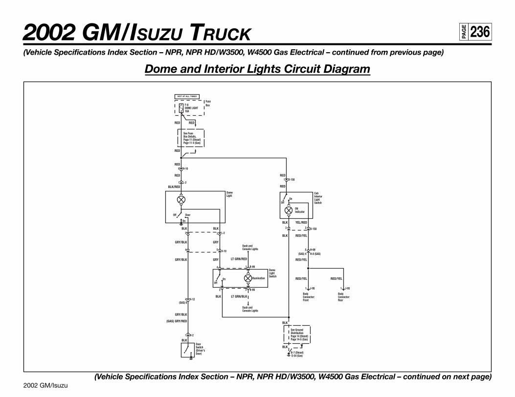
2002 GM/Isuzu
2002 GM/ISUZU TRUCK 236PA
GE
(Vehicle Specifications Index Section – NPR, NPR HD/W3500, W4500 Gas Electrical – continued from previous page)
Dome and Interior Lights Circuit Diagram
(Vehicle Specifications Index Section – NPR, NPR HD/W3500, W4500 Gas Electrical – continued on next page)
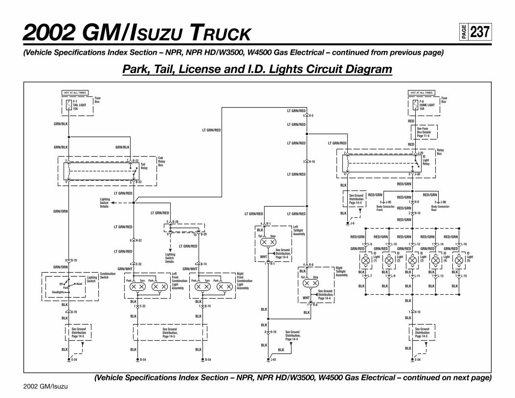
2002 GM/Isuzu
2002 GM/ISUZU TRUCK 237PA
GE
(Vehicle Specifications Index Section – NPR, NPR HD/W3500, W4500 Gas Electrical – continued from previous page)
Park, Tail, License and I.D. Lights Circuit Diagram
(Vehicle Specifications Index Section – NPR, NPR HD/W3500, W4500 Gas Electrical – continued on next page)
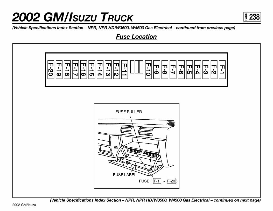
2002 GM/Isuzu
2002 GM/ISUZU TRUCK 238PA
GE
(Vehicle Specifications Index Section – NPR, NPR HD/W3500, W4500 Gas Electrical – continued from previous page)
Fuse Location
(Vehicle Specifications Index Section – NPR, NPR HD/W3500, W4500 Gas Electrical – continued on next page)
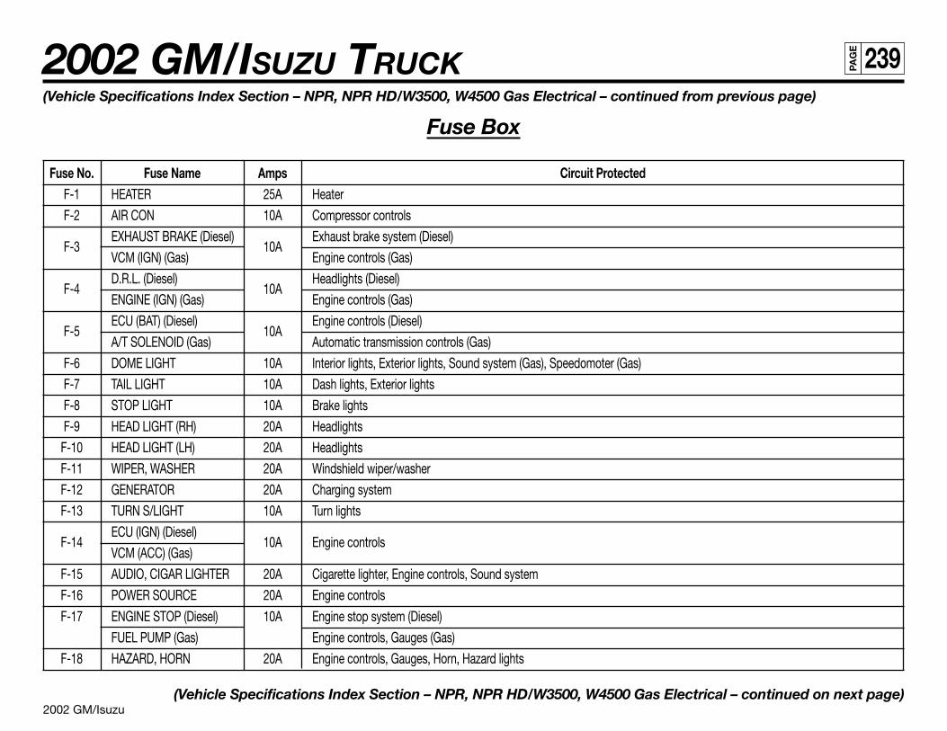
2002 GM/Isuzu
2002 GM/ISUZU TRUCK 239PA
GE
(Vehicle Specifications Index Section – NPR, NPR HD/W3500, W4500 Gas Electrical – continued from previous page)
Fuse Box
Fuse No. Fuse Name Amps Circuit ProtectedF-1 HEATER 25A Heater
F-2 AIR CON 10A Compressor controls
F-3EXHAUST BRAKE (Diesel)
10AExhaust brake system (Diesel)
VCM (IGN) (Gas) Engine controls (Gas)
F-4D.R.L. (Diesel)
10AHeadlights (Diesel)
ENGINE (IGN) (Gas) Engine controls (Gas)
F-5ECU (BAT) (Diesel)
10AEngine controls (Diesel)
A/T SOLENOID (Gas) Automatic transmission controls (Gas)
F-6 DOME LIGHT 10A Interior lights, Exterior lights, Sound system (Gas), Speedomoter (Gas)
F-7 TAIL LIGHT 10A Dash lights, Exterior lights
F-8 STOP LIGHT 10A Brake lights
F-9 HEAD LIGHT (RH) 20A Headlights
F-10 HEAD LIGHT (LH) 20A Headlights
F-11 WIPER, WASHER 20A Windshield wiper/washer
F-12 GENERATOR 20A Charging system
F-13 TURN S/LIGHT 10A Turn lights
F-14ECU (IGN) (Diesel)
10A Engine controlsVCM (ACC) (Gas)
F-15 AUDIO, CIGAR LIGHTER 20A Cigarette lighter, Engine controls, Sound system
F-16 POWER SOURCE 20A Engine controls
F-17 ENGINE STOP (Diesel) 10A Engine stop system (Diesel)
FUEL PUMP (Gas) Engine controls, Gauges (Gas)
F-18 HAZARD, HORN 20A Engine controls, Gauges, Horn, Hazard lights
(Vehicle Specifications Index Section – NPR, NPR HD/W3500, W4500 Gas Electrical – continued on next page)
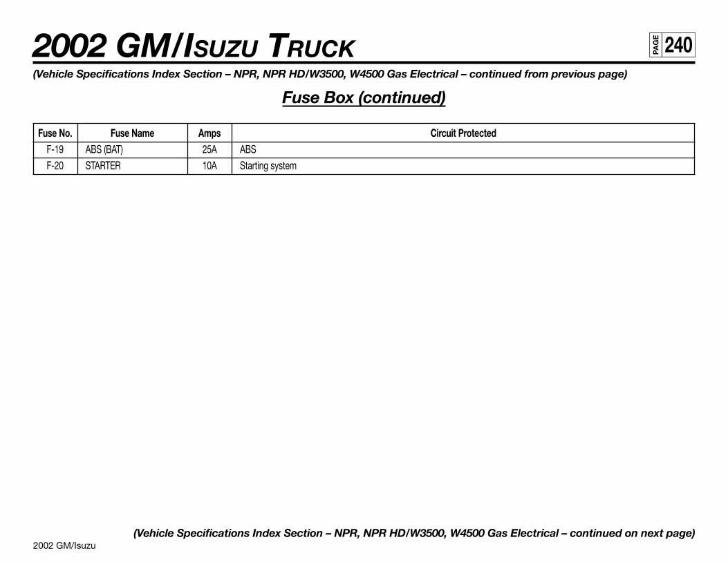
2002 GM/Isuzu
2002 GM/ISUZU TRUCK 240PA
GE
(Vehicle Specifications Index Section – NPR, NPR HD/W3500, W4500 Gas Electrical – continued from previous page)
Fuse Box (continued)
Fuse No. Fuse Name Amps Circuit ProtectedF-19 ABS (BAT) 25A ABS
F-20 STARTER 10A Starting system
(Vehicle Specifications Index Section – NPR, NPR HD/W3500, W4500 Gas Electrical – continued on next page)
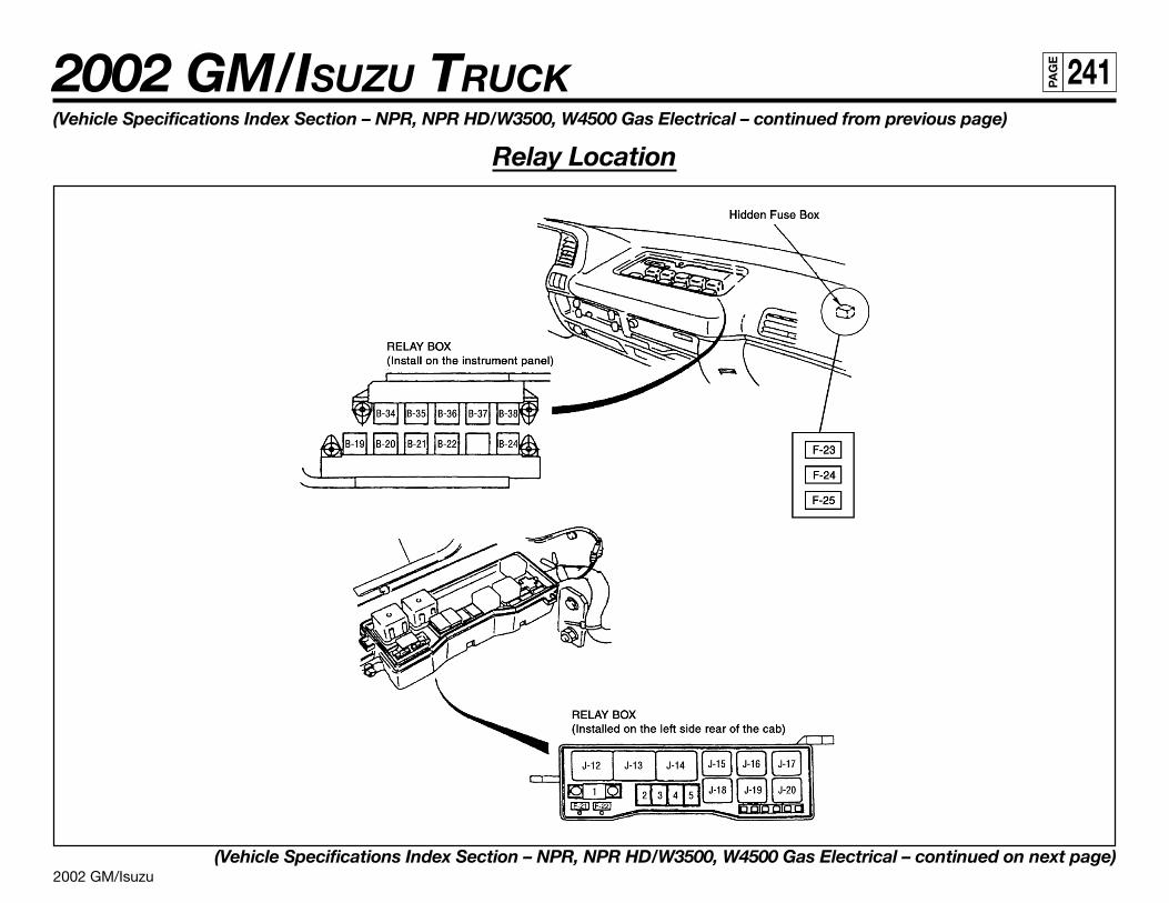
2002 GM/Isuzu
2002 GM/ISUZU TRUCK 241PA
GE
(Vehicle Specifications Index Section – NPR, NPR HD/W3500, W4500 Gas Electrical – continued from previous page)
Relay Location
(Vehicle Specifications Index Section – NPR, NPR HD/W3500, W4500 Gas Electrical – continued on next page)
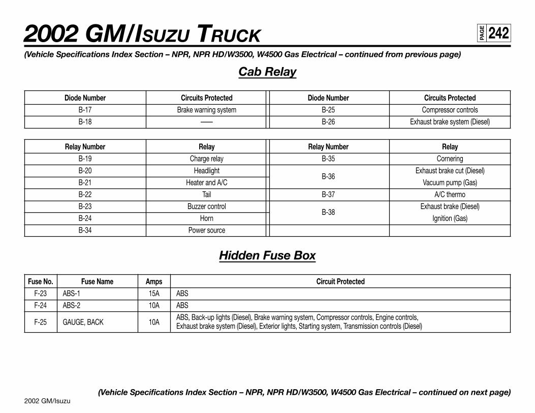
2002 GM/Isuzu
2002 GM/ISUZU TRUCK 242PA
GE
(Vehicle Specifications Index Section – NPR, NPR HD/W3500, W4500 Gas Electrical – continued from previous page)
Cab Relay
Diode Number Circuits Protected Diode Number Circuits ProtectedB-17 Brake warning system B-25 Compressor controls
B-18 —— B-26 Exhaust brake system (Diesel)
Relay Number Relay Relay Number RelayB-19 Charge relay B-35 Cornering
B-20 HeadlightB-36
Exhaust brake cut (Diesel)
B-21 Heater and A/C Vacuum pump (Gas)
B-22 Tail B-37 A/C thermo
B-23 Buzzer controlB-38
Exhaust brake (Diesel)
B-24 Horn Ignition (Gas)
B-34 Power source
Hidden Fuse Box
Fuse No. Fuse Name Amps Circuit ProtectedF-23 ABS-1 15A ABS
F-24 ABS-2 10A ABS
F-25 GAUGE, BACK 10AABS, Back-up lights (Diesel), Brake warning system, Compressor controls, Engine controls,Exhaust brake system (Diesel), Exterior lights, Starting system, Transmission controls (Diesel)
(Vehicle Specifications Index Section – NPR, NPR HD/W3500, W4500 Gas Electrical – continued on next page)
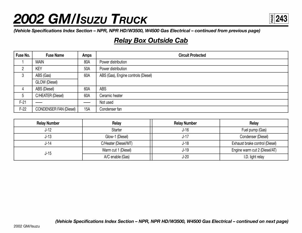
2002 GM/Isuzu
2002 GM/ISUZU TRUCK 243PA
GE
(Vehicle Specifications Index Section – NPR, NPR HD/W3500, W4500 Gas Electrical – continued from previous page)
Relay Box Outside Cab
Fuse No. Fuse Name Amps Circuit Protected1 MAIN 80A Power distribution
2 KEY 50A Power distribution
3 ABS (Gas) 60A ABS (Gas), Engine controls (Diesel)
GLOW (Diesel)
4 ABS (Diesel) 60A ABS
5 C/HEATER (Diesel) 60A Ceramic heater
F-21 —— —— Not used
F-22 CONDENSER FAN (Diesel) 15A Condenser fan
Relay Number Relay Relay Number RelayJ-12 Starter J-16 Fuel pump (Gas)
J-13 Glow-1 (Diesel) J-17 Condenser (Diesel)
J-14 C/Heater (Diesel/MT) J-18 Exhaust brake control (Diesel)
J-15Warm cut 1 (Diesel) J-19 Engine warm cut 2 (Diesel/AT)
A/C enable (Gas) J-20 I.D. light relay
(Vehicle Specifications Index Section – NPR, NPR HD/W3500, W4500 Gas Electrical – continued on next page)
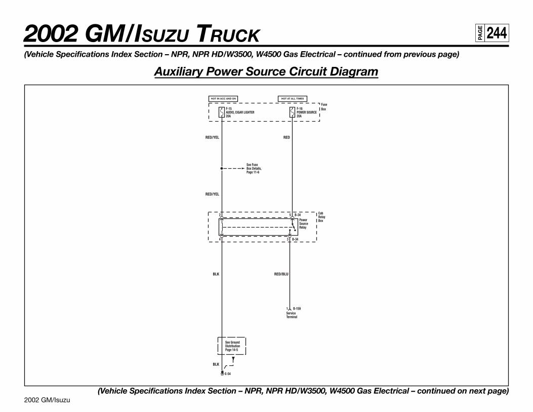
2002 GM/Isuzu
2002 GM/ISUZU TRUCK 244PA
GE
(Vehicle Specifications Index Section – NPR, NPR HD/W3500, W4500 Gas Electrical – continued from previous page)
Auxiliary Power Source Circuit Diagram
(Vehicle Specifications Index Section – NPR, NPR HD/W3500, W4500 Gas Electrical – continued on next page)
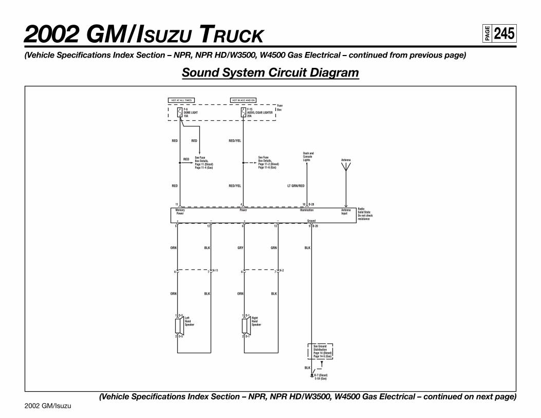
2002 GM/Isuzu
2002 GM/ISUZU TRUCK 245PA
GE
(Vehicle Specifications Index Section – NPR, NPR HD/W3500, W4500 Gas Electrical – continued from previous page)
Sound System Circuit Diagram
(Vehicle Specifications Index Section – NPR, NPR HD/W3500, W4500 Gas Electrical – continued on next page)
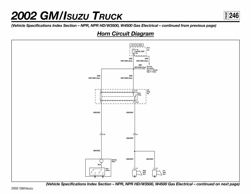
2002 GM/Isuzu
2002 GM/ISUZU TRUCK 246PA
GE
(Vehicle Specifications Index Section – NPR, NPR HD/W3500, W4500 Gas Electrical – continued from previous page)
Horn Circuit Diagram
(Vehicle Specifications Index Section – NPR, NPR HD/W3500, W4500 Gas Electrical – continued on next page)
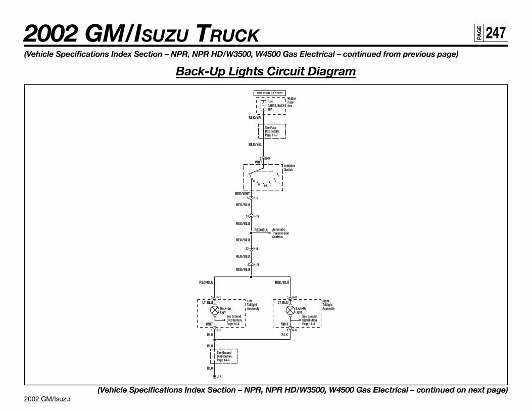
2002 GM/Isuzu
2002 GM/ISUZU TRUCK 247PA
GE
(Vehicle Specifications Index Section – NPR, NPR HD/W3500, W4500 Gas Electrical – continued from previous page)
Back-Up Lights Circuit Diagram
(Vehicle Specifications Index Section – NPR, NPR HD/W3500, W4500 Gas Electrical – continued on next page)
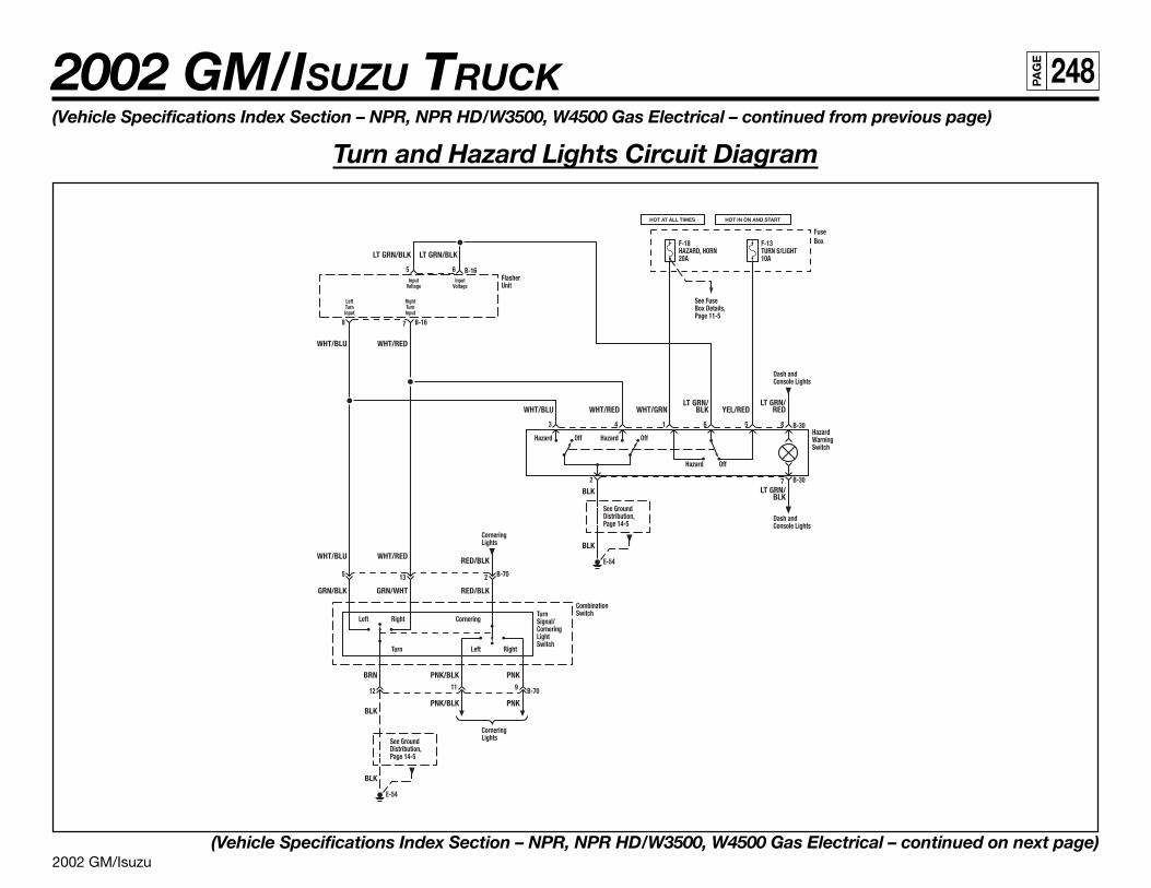
2002 GM/Isuzu
2002 GM/ISUZU TRUCK 248PA
GE
(Vehicle Specifications Index Section – NPR, NPR HD/W3500, W4500 Gas Electrical – continued from previous page)
Turn and Hazard Lights Circuit Diagram
(Vehicle Specifications Index Section – NPR, NPR HD/W3500, W4500 Gas Electrical – continued on next page)
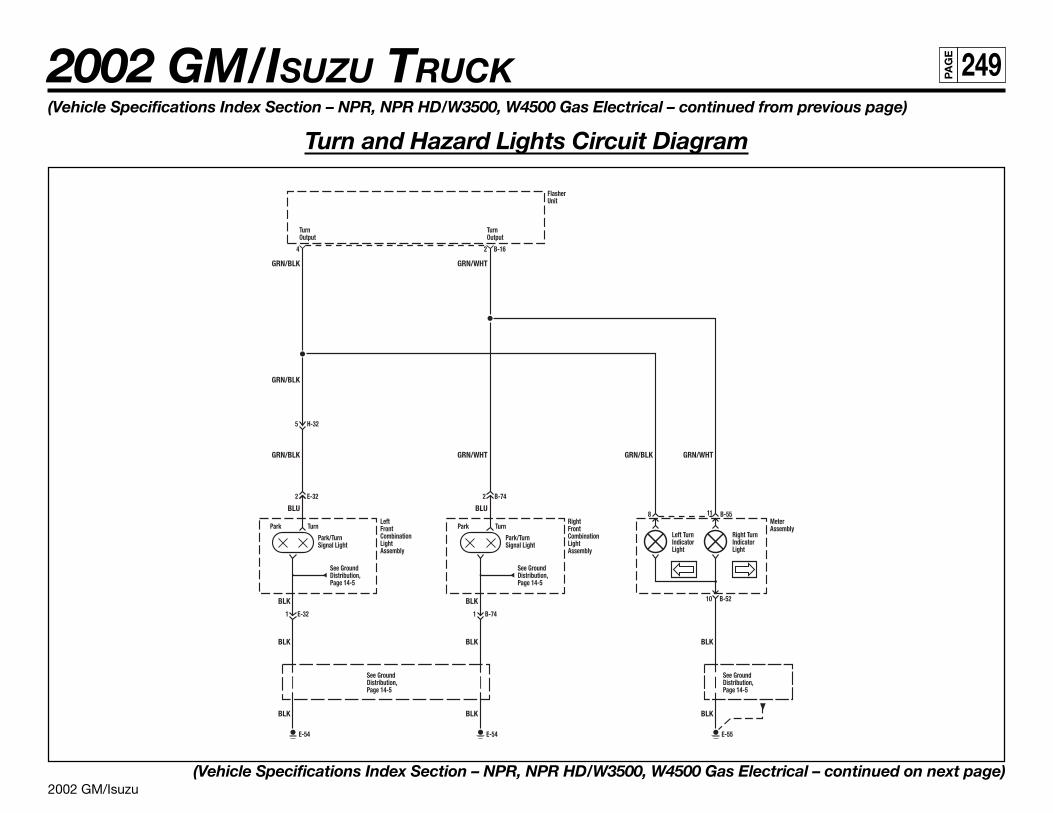
2002 GM/Isuzu
2002 GM/ISUZU TRUCK 249PA
GE
(Vehicle Specifications Index Section – NPR, NPR HD/W3500, W4500 Gas Electrical – continued from previous page)
Turn and Hazard Lights Circuit Diagram
(Vehicle Specifications Index Section – NPR, NPR HD/W3500, W4500 Gas Electrical – continued on next page)
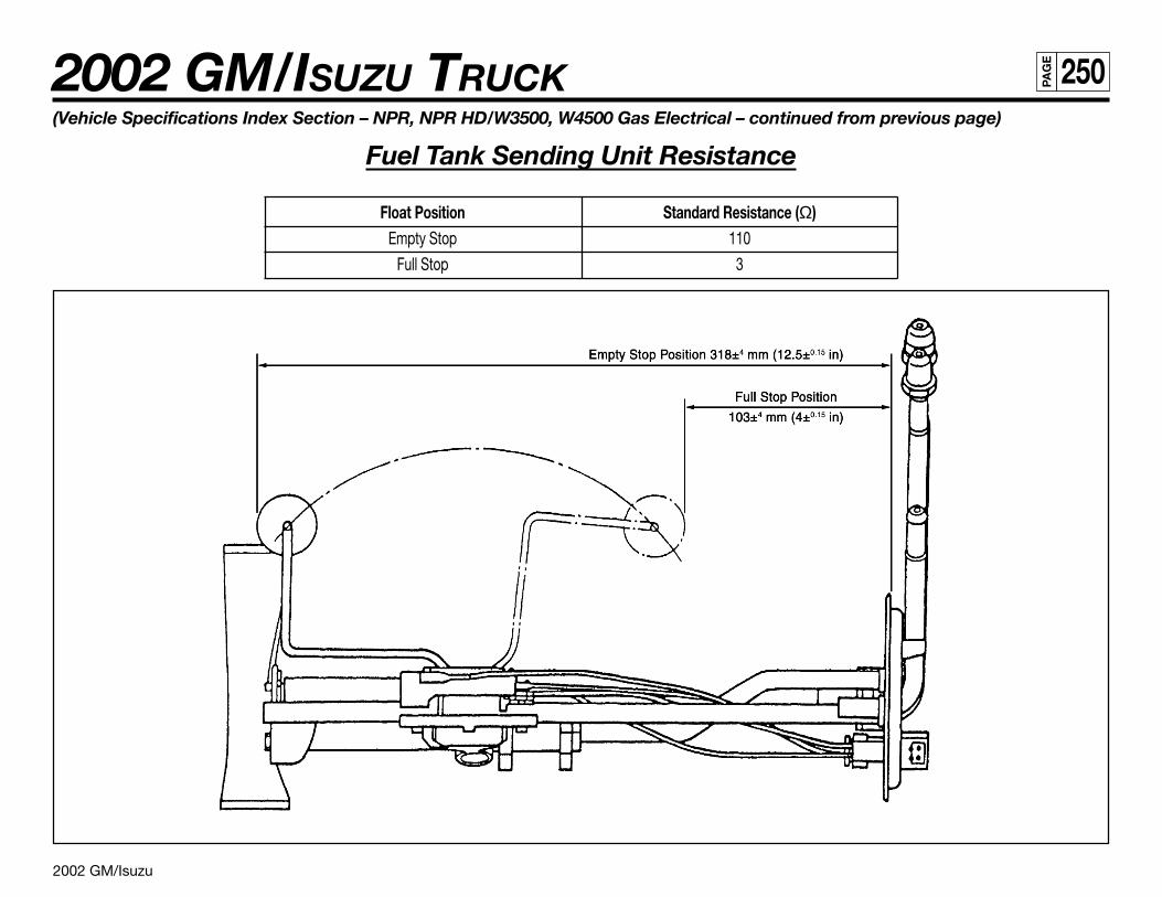
2002 GM/Isuzu
2002 GM/ISUZU TRUCK 250PA
GE
(Vehicle Specifications Index Section – NPR, NPR HD/W3500, W4500 Gas Electrical – continued from previous page)
Fuel Tank Sending Unit Resistance
Float Position Standard Resistance (Ω)Empty Stop 110
Full Stop 3
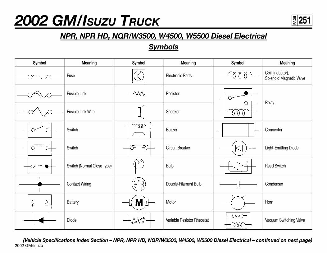
2002 GM/Isuzu
2002 GM/ISUZU TRUCK 251PA
GE
NPR, NPR HD, NQR/W3500, W4500, W5500 Diesel ElectricalSymbols
Symbol Meaning Symbol Meaning Symbol Meaning
Fuse Electronic Parts Coil (Inductor),Solenoid Magnetic Valve
Fusible Link Resistor
Relay
Fusible Link Wire Speaker
Switch Buzzer Connector
Switch Circuit Breaker Light-Emitting Diode
Switch (Normal Close Type) Bulb Reed Switch
Contact Wiring Double-Filament Bulb Condenser
Battery Motor Horn
Diode Variable Resistor Rheostat Vacuum Switching Valve
(Vehicle Specifications Index Section – NPR, NPR HD, NQR/W3500, W4500, W5500 Diesel Electrical – continued on next page)
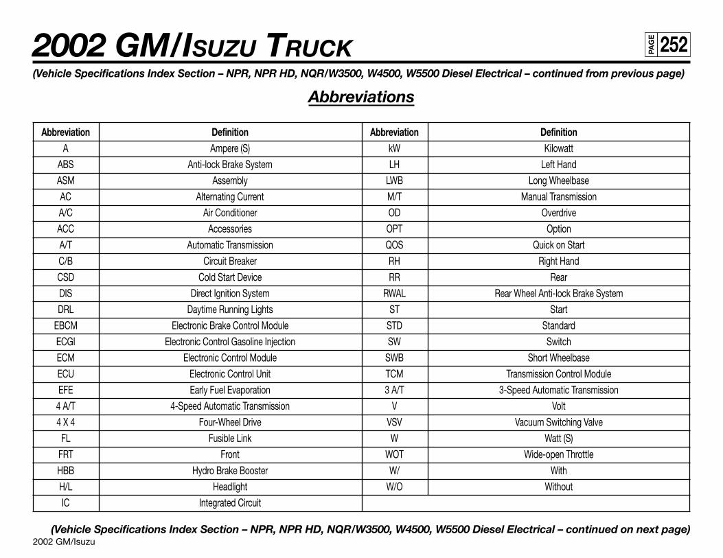
2002 GM/Isuzu
2002 GM/ISUZU TRUCK 252PA
GE
(Vehicle Specifications Index Section – NPR, NPR HD, NQR/W3500, W4500, W5500 Diesel Electrical – continued from previous page)
Abbreviations
Abbreviation Definition Abbreviation DefinitionA Ampere (S) kW Kilowatt
ABS Anti-lock Brake System LH Left Hand
ASM Assembly LWB Long Wheelbase
AC Alternating Current M/T Manual Transmission
A/C Air Conditioner OD Overdrive
ACC Accessories OPT Option
A/T Automatic Transmission QOS Quick on Start
C/B Circuit Breaker RH Right Hand
CSD Cold Start Device RR Rear
DIS Direct Ignition System RWAL Rear Wheel Anti-lock Brake System
DRL Daytime Running Lights ST Start
EBCM Electronic Brake Control Module STD Standard
ECGI Electronic Control Gasoline Injection SW Switch
ECM Electronic Control Module SWB Short Wheelbase
ECU Electronic Control Unit TCM Transmission Control Module
EFE Early Fuel Evaporation 3 A/T 3-Speed Automatic Transmission
4 A/T 4-Speed Automatic Transmission V Volt
4 X 4 Four-Wheel Drive VSV Vacuum Switching Valve
FL Fusible Link W Watt (S)
FRT Front WOT Wide-open Throttle
HBB Hydro Brake Booster W/ With
H/L Headlight W/O Without
IC Integrated Circuit
(Vehicle Specifications Index Section – NPR, NPR HD, NQR/W3500, W4500, W5500 Diesel Electrical – continued on next page)
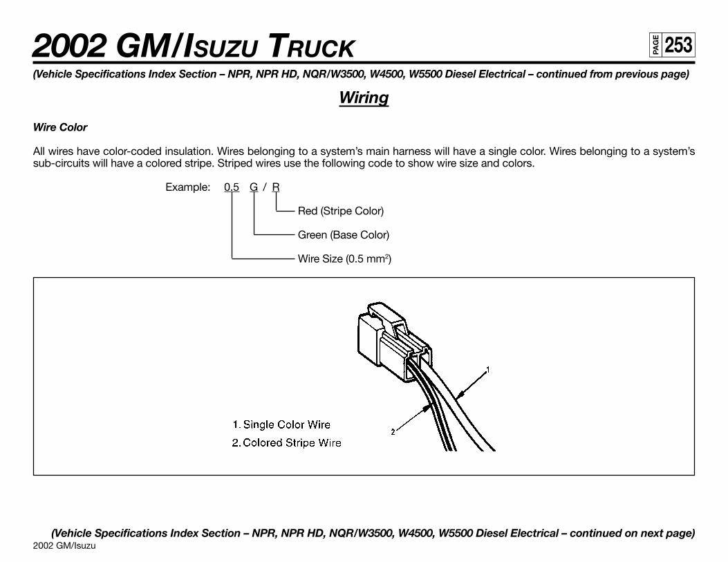
2002 GM/Isuzu
2002 GM/ISUZU TRUCK 253PA
GE
(Vehicle Specifications Index Section – NPR, NPR HD, NQR/W3500, W4500, W5500 Diesel Electrical – continued from previous page)
Wiring
Wire Color
All wires have color-coded insulation. Wires belonging to a system’s main harness will have a single color. Wires belonging to a system’ssub-circuits will have a colored stripe. Striped wires use the following code to show wire size and colors.
Example: 0.5 G / R
Red (Stripe Color)
Green (Base Color)
Wire Size (0.5 mm2)
(Vehicle Specifications Index Section – NPR, NPR HD, NQR/W3500, W4500, W5500 Diesel Electrical – continued on next page)
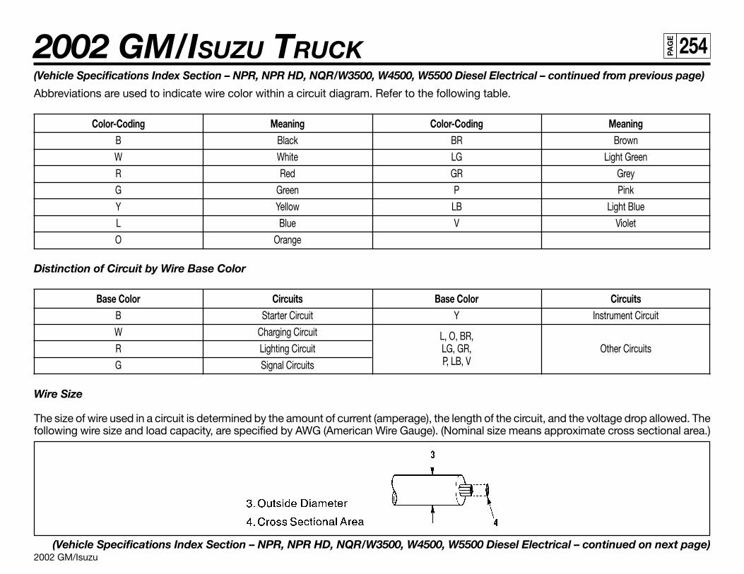
2002 GM/Isuzu
2002 GM/ISUZU TRUCK 254PA
GE
(Vehicle Specifications Index Section – NPR, NPR HD, NQR/W3500, W4500, W5500 Diesel Electrical – continued from previous page)
Abbreviations are used to indicate wire color within a circuit diagram. Refer to the following table.
Color-Coding Meaning Color-Coding MeaningB Black BR Brown
W White LG Light Green
R Red GR Grey
G Green P Pink
Y Yellow LB Light Blue
L Blue V Violet
O Orange
Distinction of Circuit by Wire Base Color
Base Color Circuits Base Color CircuitsB Starter Circuit Y Instrument Circuit
W Charging Circuit L, O, BR,R Lighting Circuit LG, GR, Other Circuits
G Signal Circuits P, LB, V
Wire Size
The size of wire used in a circuit is determined by the amount of current (amperage), the length of the circuit, and the voltage drop allowed. Thefollowing wire size and load capacity, are specified by AWG (American Wire Gauge). (Nominal size means approximate cross sectional area.)
(Vehicle Specifications Index Section – NPR, NPR HD, NQR/W3500, W4500, W5500 Diesel Electrical – continued on next page)
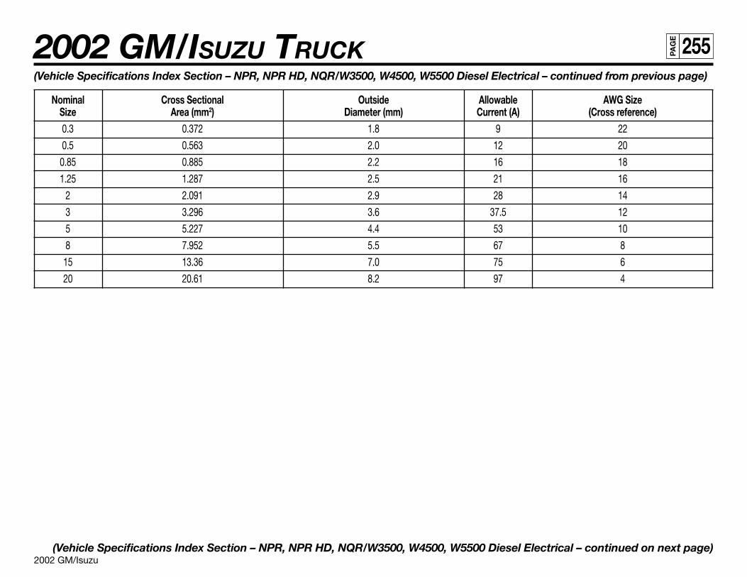
2002 GM/Isuzu
2002 GM/ISUZU TRUCK 255PA
GE
(Vehicle Specifications Index Section – NPR, NPR HD, NQR/W3500, W4500, W5500 Diesel Electrical – continued from previous page)
Nominal Cross Sectional Outside Allowable AWG SizeSize Area (mm2) Diameter (mm) Current (A) (Cross reference)0.3 0.372 1.8 9 22
0.5 0.563 2.0 12 20
0.85 0.885 2.2 16 18
1.25 1.287 2.5 21 16
2 2.091 2.9 28 14
3 3.296 3.6 37.5 12
5 5.227 4.4 53 10
8 7.952 5.5 67 8
15 13.36 7.0 75 6
20 20.61 8.2 97 4
(Vehicle Specifications Index Section – NPR, NPR HD, NQR/W3500, W4500, W5500 Diesel Electrical – continued on next page)
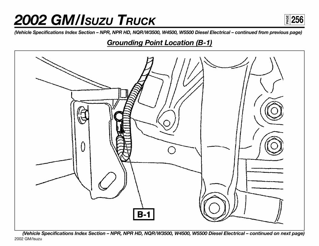
2002 GM/Isuzu
2002 GM/ISUZU TRUCK 256PA
GE
(Vehicle Specifications Index Section – NPR, NPR HD, NQR/W3500, W4500, W5500 Diesel Electrical – continued from previous page)
Grounding Point Location (B-1)
(Vehicle Specifications Index Section – NPR, NPR HD, NQR/W3500, W4500, W5500 Diesel Electrical – continued on next page)
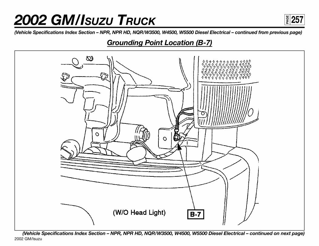
2002 GM/Isuzu
2002 GM/ISUZU TRUCK 257PA
GE
(Vehicle Specifications Index Section – NPR, NPR HD, NQR/W3500, W4500, W5500 Diesel Electrical – continued from previous page)
Grounding Point Location (B-7)
(Vehicle Specifications Index Section – NPR, NPR HD, NQR/W3500, W4500, W5500 Diesel Electrical – continued on next page)
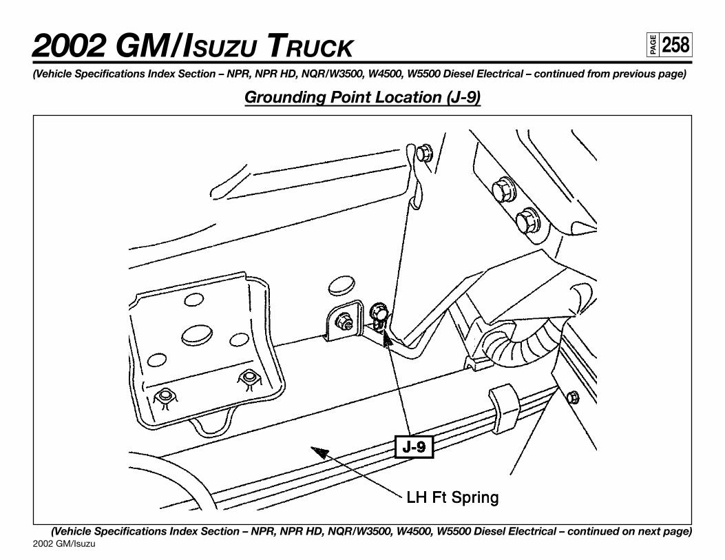
2002 GM/Isuzu
2002 GM/ISUZU TRUCK 258PA
GE
(Vehicle Specifications Index Section – NPR, NPR HD, NQR/W3500, W4500, W5500 Diesel Electrical – continued from previous page)
Grounding Point Location (J-9)
(Vehicle Specifications Index Section – NPR, NPR HD, NQR/W3500, W4500, W5500 Diesel Electrical – continued on next page)
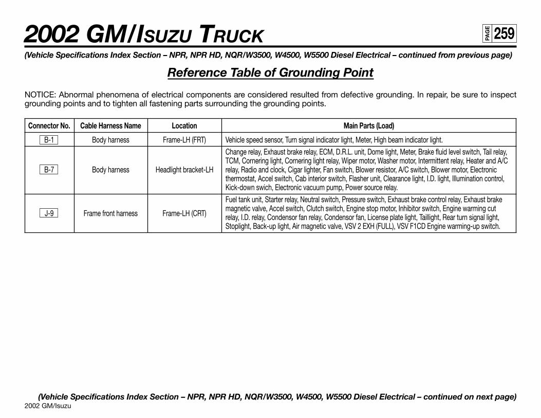
2002 GM/Isuzu
2002 GM/ISUZU TRUCK 259PA
GE
(Vehicle Specifications Index Section – NPR, NPR HD, NQR/W3500, W4500, W5500 Diesel Electrical – continued from previous page)
Reference Table of Grounding Point
NOTICE: Abnormal phenomena of electrical components are considered resulted from defective grounding. In repair, be sure to inspectgrounding points and to tighten all fastening parts surrounding the grounding points.
Connector No. Cable Harness Name Location Main Parts (Load)
B-1 Body harness Frame-LH (FRT) Vehicle speed sensor, Turn signal indicator light, Meter, High beam indicator light.
Change relay, Exhaust brake relay, ECM, D.R.L. unit, Dome light, Meter, Brake fluid level switch, Tail relay,TCM, Cornering light, Cornering light relay, Wiper motor, Washer motor, Intermittent relay, Heater and A/C
B-7 Body harness Headlight bracket-LH relay, Radio and clock, Cigar lighter, Fan switch, Blower resistor, A/C switch, Blower motor, Electronicthermostat, Accel switch, Cab interior switch, Flasher unit, Clearance light, I.D. light, Illumination control,Kick-down swich, Electronic vacuum pump, Power source relay.
Fuel tank unit, Starter relay, Neutral switch, Pressure switch, Exhaust brake control relay, Exhaust brake
J-9 Frame front harness Frame-LH (CRT)magnetic valve, Accel switch, Clutch switch, Engine stop motor, Inhibitor switch, Engine warming cutrelay, I.D. relay, Condensor fan relay, Condensor fan, License plate light, Taillight, Rear turn signal light,Stoplight, Back-up light, Air magnetic valve, VSV 2 EXH (FULL), VSV F1CD Engine warming-up switch.
(Vehicle Specifications Index Section – NPR, NPR HD, NQR/W3500, W4500, W5500 Diesel Electrical – continued on next page)
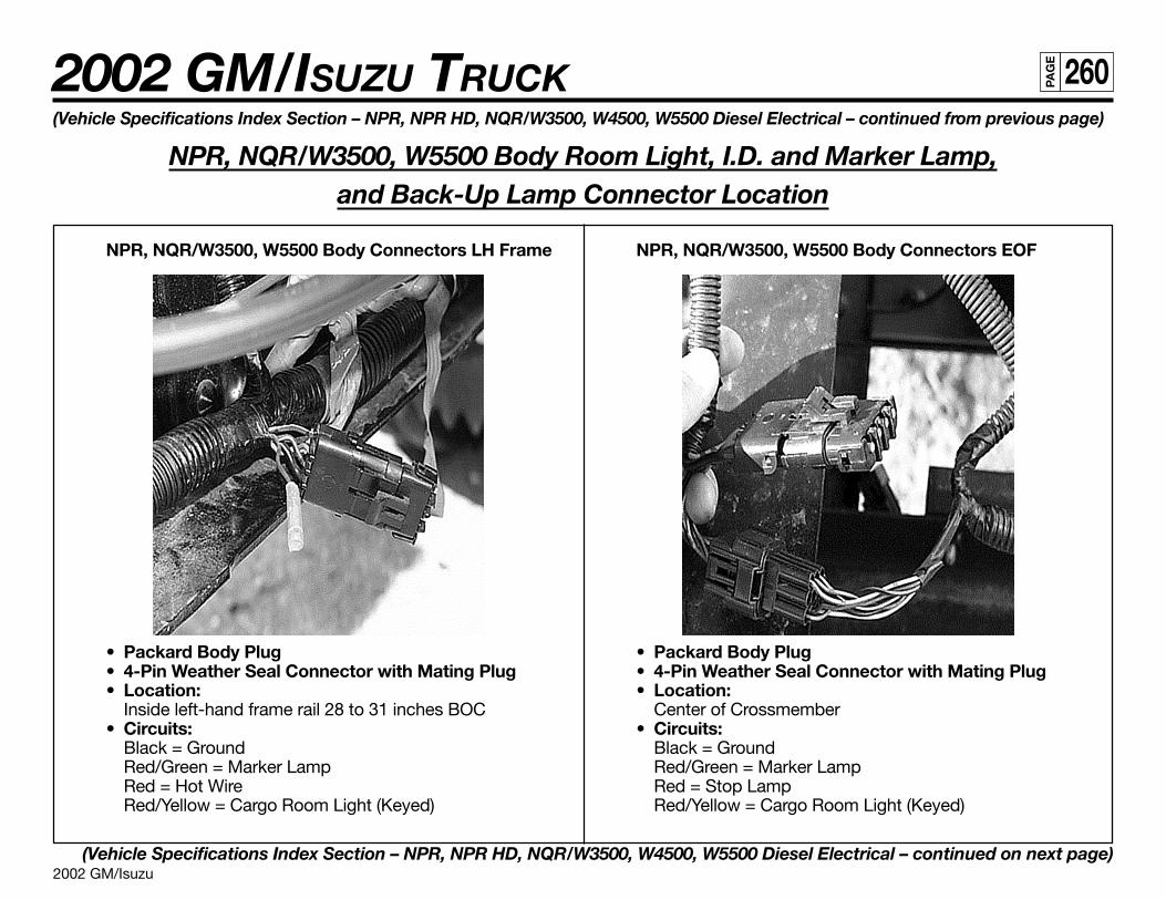
2002 GM/Isuzu
2002 GM/ISUZU TRUCK 260PA
GE
(Vehicle Specifications Index Section – NPR, NPR HD, NQR/W3500, W4500, W5500 Diesel Electrical – continued from previous page)
NPR, NQR/W3500, W5500 Body Room Light, I.D. and Marker Lamp,and Back-Up Lamp Connector Location
(Vehicle Specifications Index Section – NPR, NPR HD, NQR/W3500, W4500, W5500 Diesel Electrical – continued on next page)
NPR, NQR/W3500, W5500 Body Connectors LH Frame
• Packard Body Plug• 4-Pin Weather Seal Connector with Mating Plug• Location:
Inside left-hand frame rail 28 to 31 inches BOC• Circuits:
Black = GroundRed/Green = Marker LampRed = Hot WireRed/Yellow = Cargo Room Light (Keyed)
NPR, NQR/W3500, W5500 Body Connectors EOF
• Packard Body Plug• 4-Pin Weather Seal Connector with Mating Plug• Location:
Center of Crossmember• Circuits:
Black = GroundRed/Green = Marker LampRed = Stop LampRed/Yellow = Cargo Room Light (Keyed)
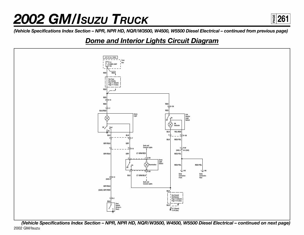
2002 GM/Isuzu
2002 GM/ISUZU TRUCK 261PA
GE
(Vehicle Specifications Index Section – NPR, NPR HD, NQR/W3500, W4500, W5500 Diesel Electrical – continued from previous page)
Dome and Interior Lights Circuit Diagram
(Vehicle Specifications Index Section – NPR, NPR HD, NQR/W3500, W4500, W5500 Diesel Electrical – continued on next page)
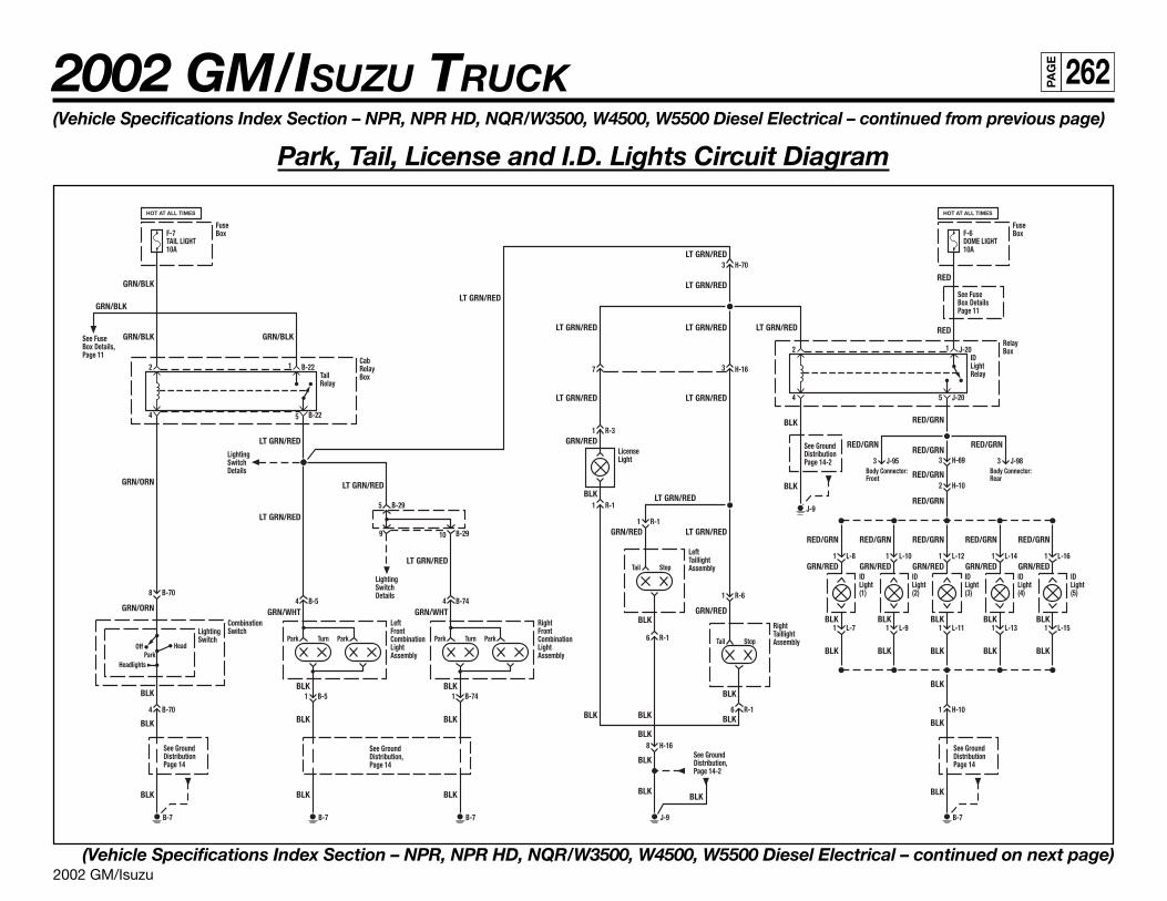
2002 GM/Isuzu
2002 GM/ISUZU TRUCK 262PA
GE
(Vehicle Specifications Index Section – NPR, NPR HD, NQR/W3500, W4500, W5500 Diesel Electrical – continued from previous page)
Park, Tail, License and I.D. Lights Circuit Diagram
(Vehicle Specifications Index Section – NPR, NPR HD, NQR/W3500, W4500, W5500 Diesel Electrical – continued on next page)
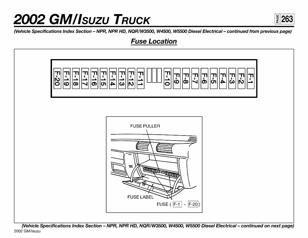
2002 GM/Isuzu
2002 GM/ISUZU TRUCK 263PA
GE
(Vehicle Specifications Index Section – NPR, NPR HD, NQR/W3500, W4500, W5500 Diesel Electrical – continued from previous page)
Fuse Location
(Vehicle Specifications Index Section – NPR, NPR HD, NQR/W3500, W4500, W5500 Diesel Electrical – continued on next page)
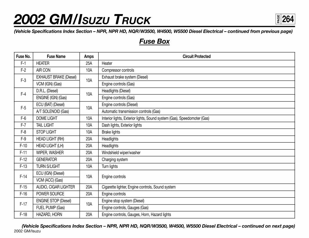
2002 GM/Isuzu
2002 GM/ISUZU TRUCK 264PA
GE
(Vehicle Specifications Index Section – NPR, NPR HD, NQR/W3500, W4500, W5500 Diesel Electrical – continued from previous page)
Fuse Box
Fuse No. Fuse Name Amps Circuit ProtectedF-1 HEATER 25A Heater
F-2 AIR CON 10A Compressor controls
F-3EXHAUST BRAKE (Diesel)
10AExhaust brake system (Diesel)
VCM (IGN) (Gas) Engine controls (Gas)
F-4D.R.L. (Diesel)
10AHeadlights (Diesel)
ENGINE (IGN) (Gas) Engine controls (Gas)
F-5ECU (BAT) (Diesel)
10AEngine controls (Diesel)
A/T SOLENOID (Gas) Automatic transmission controls (Gas)
F-6 DOME LIGHT 10A Interior lights, Exterior lights, Sound system (Gas), Speedomoter (Gas)
F-7 TAIL LIGHT 10A Dash lights, Exterior lights
F-8 STOP LIGHT 10A Brake lights
F-9 HEAD LIGHT (RH) 20A Headlights
F-10 HEAD LIGHT (LH) 20A Headlights
F-11 WIPER, WASHER 20A Windshield wiper/washer
F-12 GENERATOR 20A Charging system
F-13 TURN S/LIGHT 10A Turn lights
F-14ECU (IGN) (Diesel)
10A Engine controlsVCM (ACC) (Gas)
F-15 AUDIO, CIGAR LIGHTER 20A Cigarette lighter, Engine controls, Sound system
F-16 POWER SOURCE 20A Engine controls
F-17ENGINE STOP (Diesel)
10AEngine stop system (Diesel)
FUEL PUMP (Gas) Engine controls, Gauges (Gas)
F-18 HAZARD, HORN 20A Engine controls, Gauges, Horn, Hazard lights
(Vehicle Specifications Index Section – NPR, NPR HD, NQR/W3500, W4500, W5500 Diesel Electrical – continued on next page)
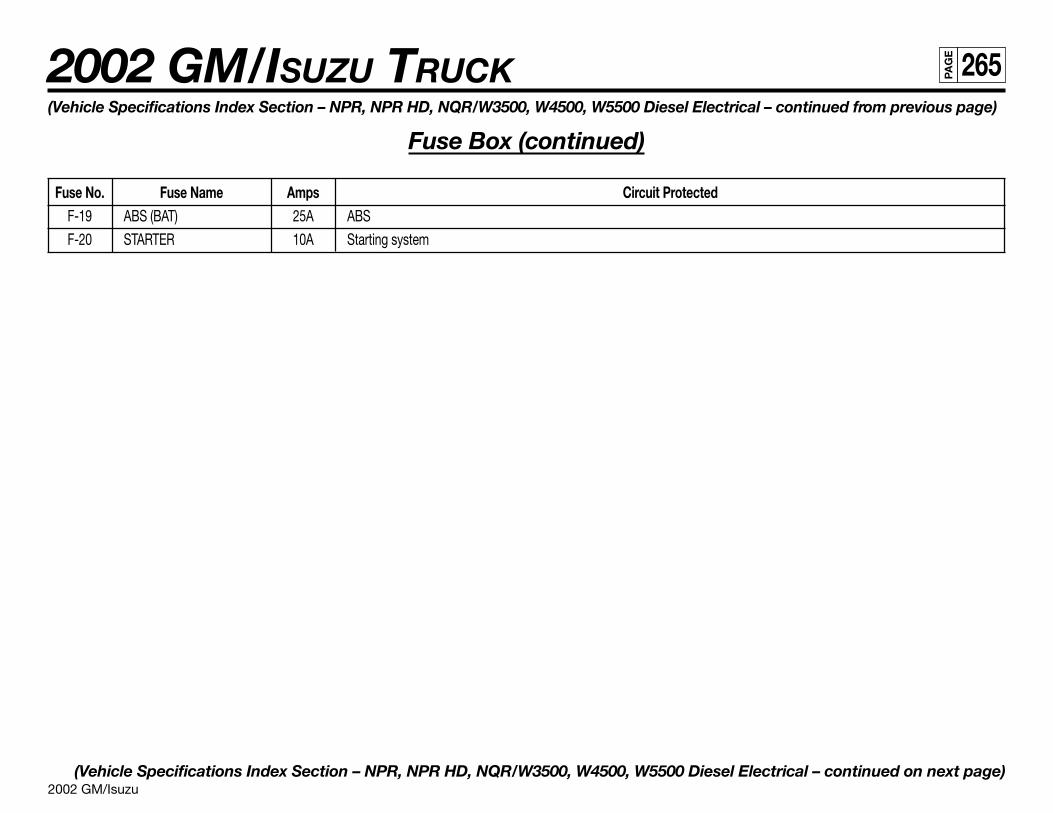
2002 GM/Isuzu
2002 GM/ISUZU TRUCK 265PA
GE
(Vehicle Specifications Index Section – NPR, NPR HD, NQR/W3500, W4500, W5500 Diesel Electrical – continued from previous page)
Fuse Box (continued)
Fuse No. Fuse Name Amps Circuit ProtectedF-19 ABS (BAT) 25A ABS
F-20 STARTER 10A Starting system
(Vehicle Specifications Index Section – NPR, NPR HD, NQR/W3500, W4500, W5500 Diesel Electrical – continued on next page)
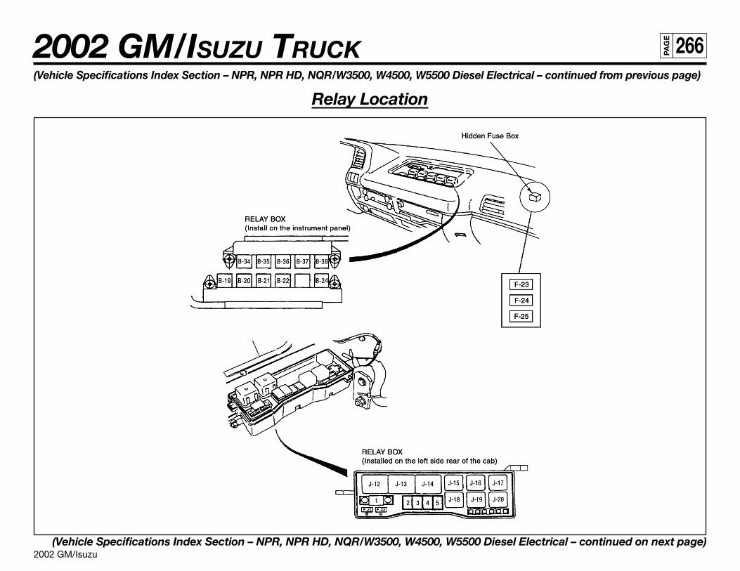
2002 GM/Isuzu
2002 GM/ISUZU TRUCK 266PA
GE
(Vehicle Specifications Index Section – NPR, NPR HD, NQR/W3500, W4500, W5500 Diesel Electrical – continued from previous page)
Relay Location
(Vehicle Specifications Index Section – NPR, NPR HD, NQR/W3500, W4500, W5500 Diesel Electrical – continued on next page)
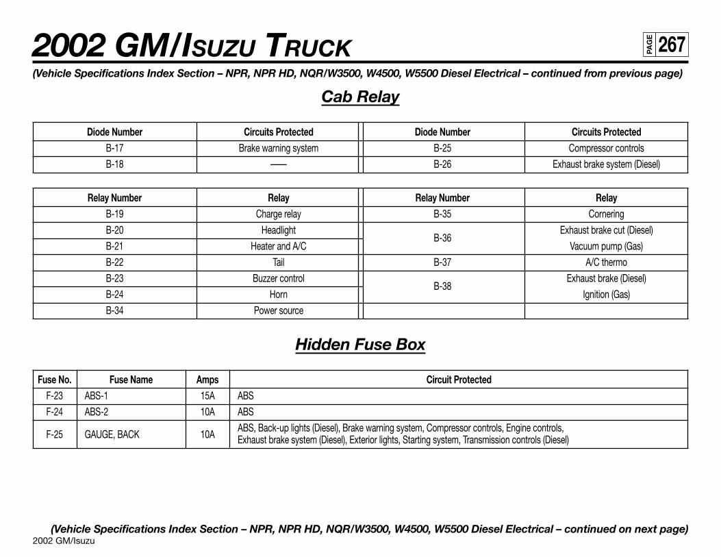
2002 GM/Isuzu
2002 GM/ISUZU TRUCK 267PA
GE
(Vehicle Specifications Index Section – NPR, NPR HD, NQR/W3500, W4500, W5500 Diesel Electrical – continued from previous page)
Cab Relay
Diode Number Circuits Protected Diode Number Circuits ProtectedB-17 Brake warning system B-25 Compressor controls
B-18 —— B-26 Exhaust brake system (Diesel)
Relay Number Relay Relay Number RelayB-19 Charge relay B-35 Cornering
B-20 HeadlightB-36
Exhaust brake cut (Diesel)
B-21 Heater and A/C Vacuum pump (Gas)
B-22 Tail B-37 A/C thermo
B-23 Buzzer controlB-38
Exhaust brake (Diesel)
B-24 Horn Ignition (Gas)
B-34 Power source
Hidden Fuse Box
Fuse No. Fuse Name Amps Circuit ProtectedF-23 ABS-1 15A ABS
F-24 ABS-2 10A ABS
F-25 GAUGE, BACK 10AABS, Back-up lights (Diesel), Brake warning system, Compressor controls, Engine controls,Exhaust brake system (Diesel), Exterior lights, Starting system, Transmission controls (Diesel)
(Vehicle Specifications Index Section – NPR, NPR HD, NQR/W3500, W4500, W5500 Diesel Electrical – continued on next page)
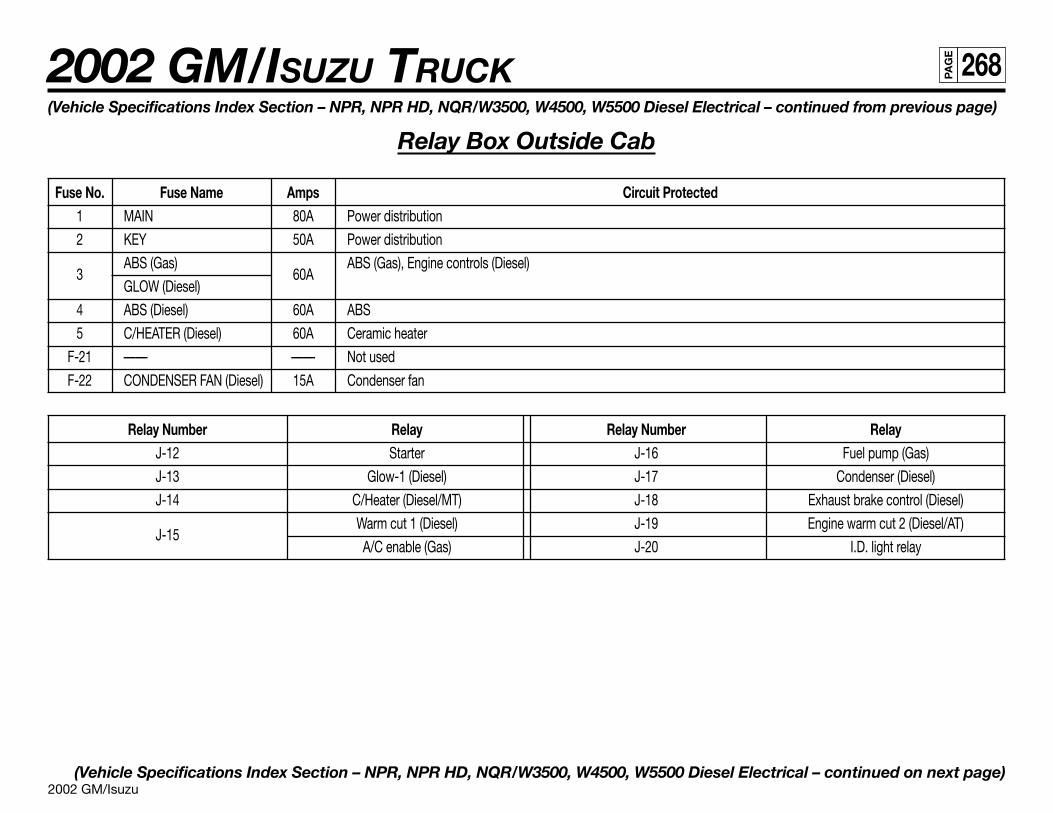
2002 GM/Isuzu
2002 GM/ISUZU TRUCK 268PA
GE
(Vehicle Specifications Index Section – NPR, NPR HD, NQR/W3500, W4500, W5500 Diesel Electrical – continued from previous page)
Relay Box Outside Cab
Fuse No. Fuse Name Amps Circuit Protected1 MAIN 80A Power distribution
2 KEY 50A Power distribution
3ABS (Gas)
60AABS (Gas), Engine controls (Diesel)
GLOW (Diesel)
4 ABS (Diesel) 60A ABS
5 C/HEATER (Diesel) 60A Ceramic heater
F-21 —— —— Not used
F-22 CONDENSER FAN (Diesel) 15A Condenser fan
Relay Number Relay Relay Number RelayJ-12 Starter J-16 Fuel pump (Gas)
J-13 Glow-1 (Diesel) J-17 Condenser (Diesel)
J-14 C/Heater (Diesel/MT) J-18 Exhaust brake control (Diesel)
J-15Warm cut 1 (Diesel) J-19 Engine warm cut 2 (Diesel/AT)
A/C enable (Gas) J-20 I.D. light relay
(Vehicle Specifications Index Section – NPR, NPR HD, NQR/W3500, W4500, W5500 Diesel Electrical – continued on next page)
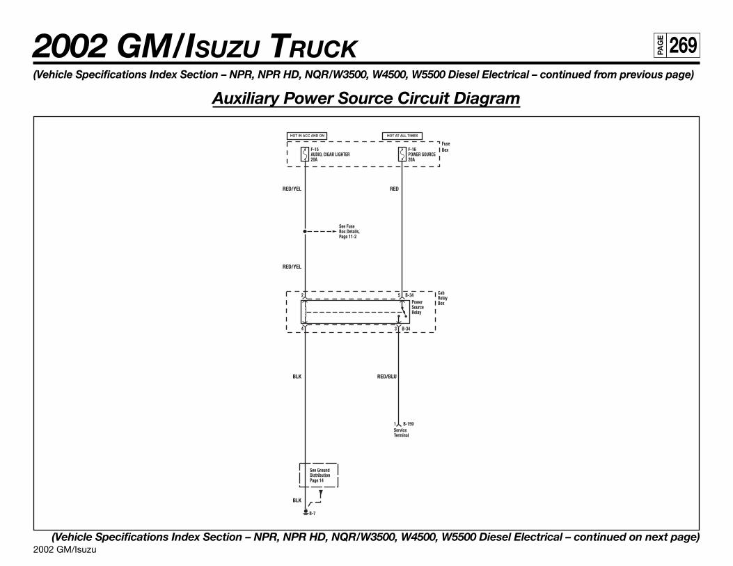
2002 GM/Isuzu
2002 GM/ISUZU TRUCK 269PA
GE
(Vehicle Specifications Index Section – NPR, NPR HD, NQR/W3500, W4500, W5500 Diesel Electrical – continued from previous page)
Auxiliary Power Source Circuit Diagram
(Vehicle Specifications Index Section – NPR, NPR HD, NQR/W3500, W4500, W5500 Diesel Electrical – continued on next page)
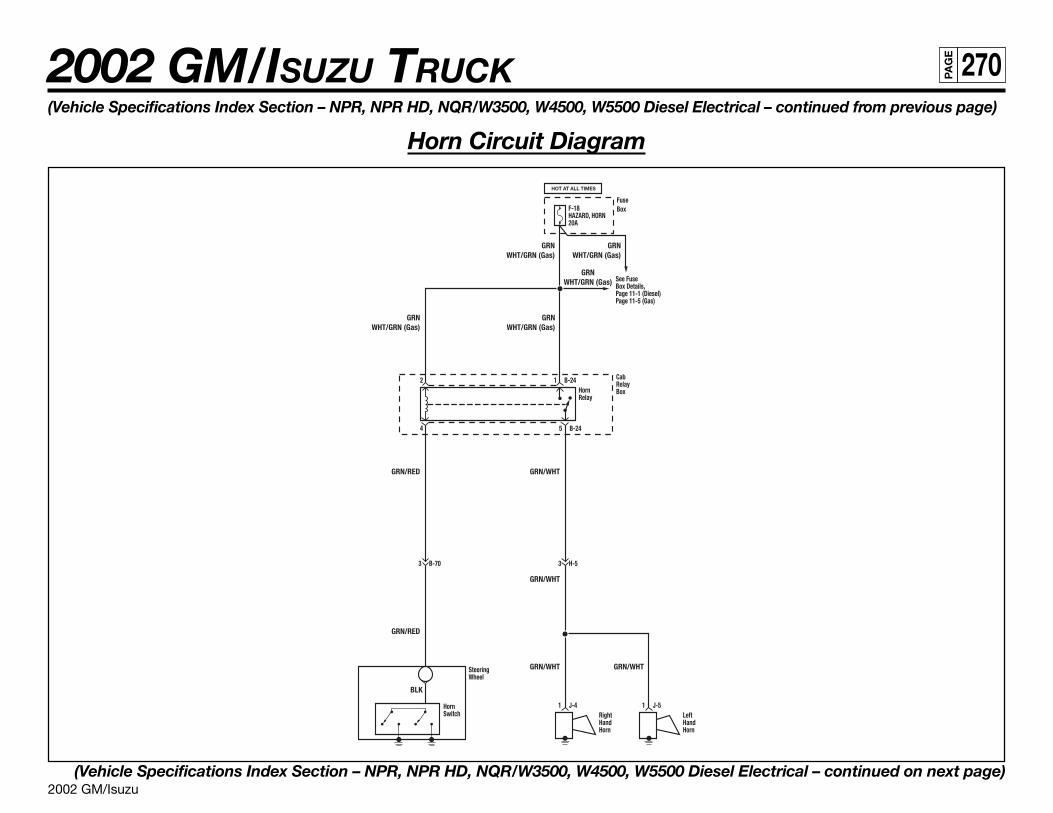
2002 GM/Isuzu
2002 GM/ISUZU TRUCK 270PA
GE
(Vehicle Specifications Index Section – NPR, NPR HD, NQR/W3500, W4500, W5500 Diesel Electrical – continued from previous page)
Horn Circuit Diagram
(Vehicle Specifications Index Section – NPR, NPR HD, NQR/W3500, W4500, W5500 Diesel Electrical – continued on next page)
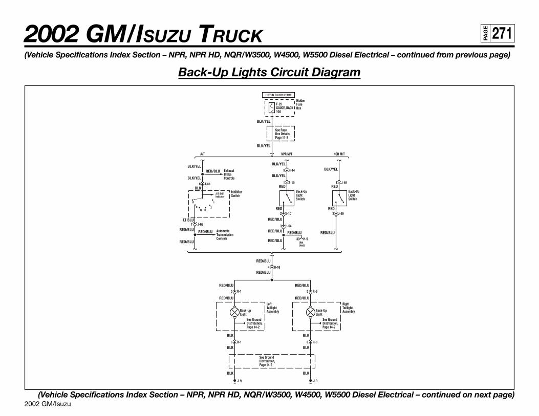
2002 GM/Isuzu
2002 GM/ISUZU TRUCK 271PA
GE
(Vehicle Specifications Index Section – NPR, NPR HD, NQR/W3500, W4500, W5500 Diesel Electrical – continued from previous page)
Back-Up Lights Circuit Diagram
(Vehicle Specifications Index Section – NPR, NPR HD, NQR/W3500, W4500, W5500 Diesel Electrical – continued on next page)
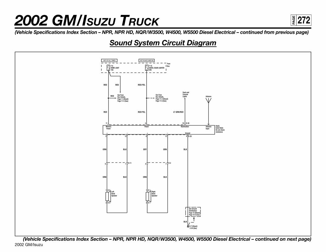
2002 GM/Isuzu
2002 GM/ISUZU TRUCK 272PA
GE
(Vehicle Specifications Index Section – NPR, NPR HD, NQR/W3500, W4500, W5500 Diesel Electrical – continued from previous page)
Sound System Circuit Diagram
(Vehicle Specifications Index Section – NPR, NPR HD, NQR/W3500, W4500, W5500 Diesel Electrical – continued on next page)
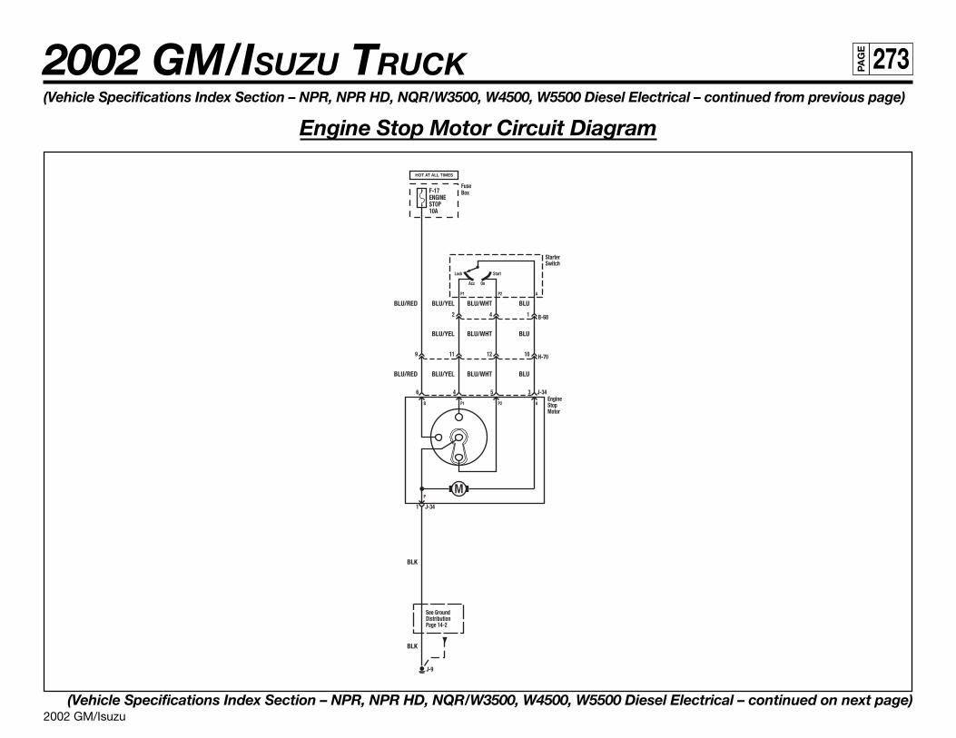
2002 GM/Isuzu
2002 GM/ISUZU TRUCK 273PA
GE
(Vehicle Specifications Index Section – NPR, NPR HD, NQR/W3500, W4500, W5500 Diesel Electrical – continued from previous page)
Engine Stop Motor Circuit Diagram
(Vehicle Specifications Index Section – NPR, NPR HD, NQR/W3500, W4500, W5500 Diesel Electrical – continued on next page)
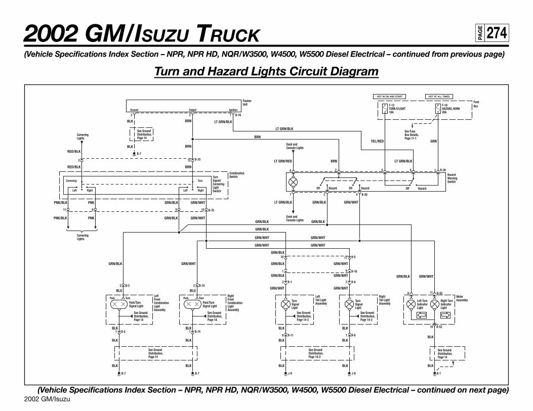
2002 GM/Isuzu
2002 GM/ISUZU TRUCK 274PA
GE
(Vehicle Specifications Index Section – NPR, NPR HD, NQR/W3500, W4500, W5500 Diesel Electrical – continued from previous page)
Turn and Hazard Lights Circuit Diagram
(Vehicle Specifications Index Section – NPR, NPR HD, NQR/W3500, W4500, W5500 Diesel Electrical – continued on next page)
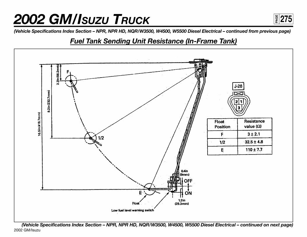
2002 GM/Isuzu
2002 GM/ISUZU TRUCK 275PA
GE
(Vehicle Specifications Index Section – NPR, NPR HD, NQR/W3500, W4500, W5500 Diesel Electrical – continued from previous page)
Fuel Tank Sending Unit Resistance (In-Frame Tank)
(Vehicle Specifications Index Section – NPR, NPR HD, NQR/W3500, W4500, W5500 Diesel Electrical – continued on next page)
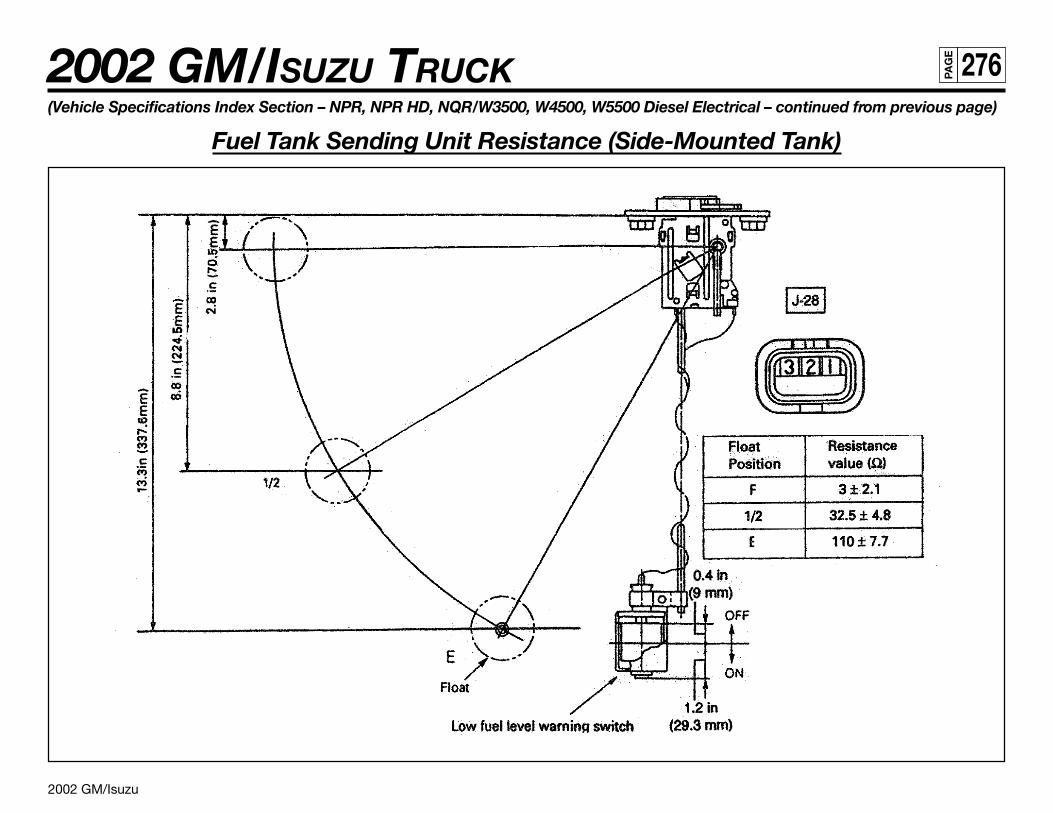
2002 GM/Isuzu
2002 GM/ISUZU TRUCK 276PA
GE
(Vehicle Specifications Index Section – NPR, NPR HD, NQR/W3500, W4500, W5500 Diesel Electrical – continued from previous page)
Fuel Tank Sending Unit Resistance (Side-Mounted Tank)
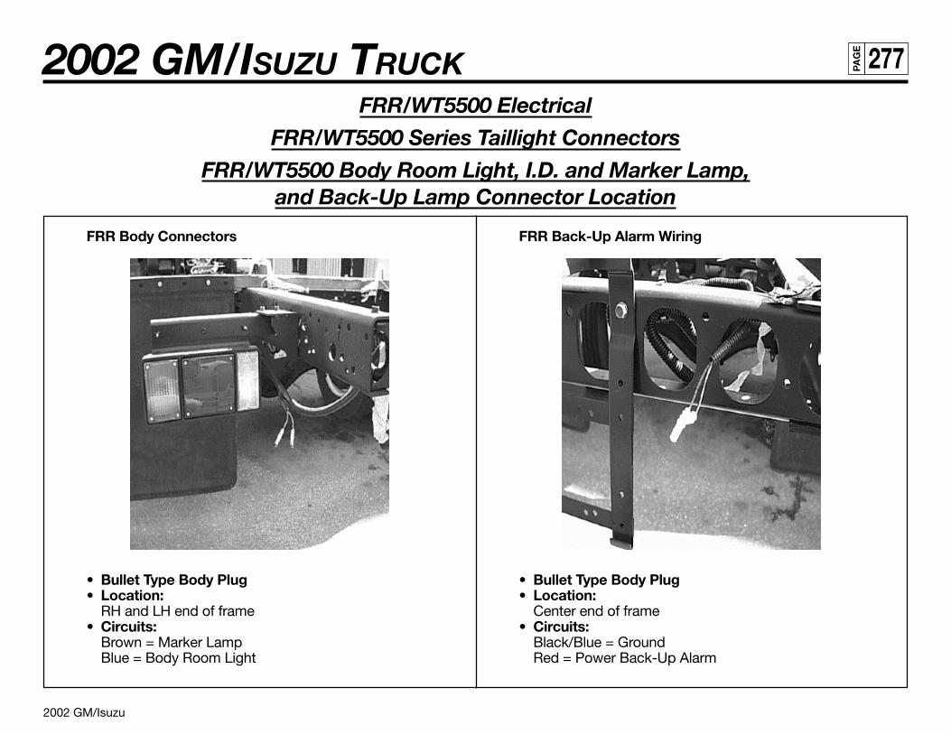
2002 GM/Isuzu
2002 GM/ISUZU TRUCK 277PA
GE
FRR/WT5500 Electrical
FRR/WT5500 Series Taillight Connectors
FRR/WT5500 Body Room Light, I.D. and Marker Lamp,and Back-Up Lamp Connector Location
FRR Body Connectors
• Bullet Type Body Plug• Location:
RH and LH end of frame• Circuits:
Brown = Marker LampBlue = Body Room Light
FRR Back-Up Alarm Wiring
• Bullet Type Body Plug• Location:
Center end of frame• Circuits:
Black/Blue = GroundRed = Power Back-Up Alarm