2001V Series Peristaltic Chemical Feed Pump€¦ · 1.0 - System Overview The 2001V Chemical Feed...
21
2001V Series Peristaltic Chemical Feed Pump
Transcript of 2001V Series Peristaltic Chemical Feed Pump€¦ · 1.0 - System Overview The 2001V Chemical Feed...

2001V Series Peristaltic Chemical Feed Pump

Installation and Operation Manual
2001V Peristaltic Chemical Feed Pump
December 2019
Flomotion Systems, Inc.3 N. Main St, Middleport, NY 14105
Toll Free: (800)909-3569 (U.S. & Canada)Tel: (716)691-3941Fax: (716)691-1253

TABLE OF CONTENTS
1.0 - System Overview.......................................................................................................................................................... 5
1.1 SAFETY...............................................................................................................................................................................................51.2 WARRANTY.........................................................................................................................................................................................51.3 RECEIVING..........................................................................................................................................................................................61.4 CUSTOMER MODIFICATION...................................................................................................................................................................61.5 INFORMATION FOR RETURNING PUMPS ................................................................................................................................................6
2.0 – 2001V Series Pump and Pumphead............................................................................................................................ 7
2.1 TUBING, SPINDLE AND COVER INSTALLATION.......................................................................................................................................82.2 MOUNTING PUMP ON GEARBOX, INSTALLATION OF COLLET.................................................................................................................92.3 PUMP MOUNTING AND COLLET INSTALLATION PROCEDURE................................................................................................................102.4 HOSE AND ROLLER INSTALLATION.....................................................................................................................................................102.5 TUBING & CONNECTIONS...................................................................................................................................................................16
3.0 – 2001V Series Gearbox............................................................................................................................................... 18
3.1 RUN-IN PERIOD.................................................................................................................................................................................183.2 MAINTENANCE..................................................................................................................................................................................183.3 2001V SERIES MOTOR / GEARBOX SPECIFICATIONS ..........................................................................................................................183.4 2001V SERIES POWER & MOTOR WIRING.........................................................................................................................................18
4.0 – 2001V Series Drive Controller.................................................................................................................................... 20
4.1 OPERATION AND WIRING...................................................................................................................................................................204.2 PROGRAMMING .................................................................................................................................................................................204.3 MANUAL SPEED / AUTO SPEED / RESTART TOGGLE SWITCH...............................................................................................................20
5.0 - 2001 Series Tubing Rupture Detector.........................................................................................................................21
5.1 ALARM CAUSES.................................................................................................................................................................................215.2 WHAT TO DO IN AN ALARM CONDITION...............................................................................................................................................215.3 RESETTING THE ALARM......................................................................................................................................................................215.4 RESUMING SERVICE...........................................................................................................................................................................215.5 INTERFACING.....................................................................................................................................................................................225.6 CALIBRATION....................................................................................................................................................................................22

1.0 - System Overview
The 2001V Chemical Feed Pump consists of a controller, motor, gearbox and peristaltic pump.
1.1 SafetyIn the interests of safety, this pump and the tubing selected should only be used by competent, suitably trainedpersonnel after they have read and understood this manual, and considered any hazard involved. Any person who is involved in the installation or maintenance of this equipment should be fully competent to carry out the work.
Maintenance and repair should be performed by qualified personnel only. Make sure that no voltage is applied while work is being carried out on the pump or motor. The motor must be secured against accidental start up.
1.2 ReceivingInspect all cartons for damage, which may have occurred during shipping. Carefully unpack equipment and inspect thoroughly for damage or shortage. Report any damage to carrier and/or shortages to supplier. All major components and connections should be examined for damage and tightness, with special attention givento PC boards, plugs, knobs and switches.
1.3 Customer ModificationFlomotion Systems, Inc., its sales representatives and distributors, welcome the opportunity to assist our customers in applying our products. Many customizing options are available to aid in this function. Flomotion Systems, Inc. cannot assume responsibility for any modifications not authorized by its engineering department.
1.4 Information for Returning Pumps Equipment that has been contaminated with, or exposed to, body fluids, toxic chemicals or any other substance hazardous to health must be decontaminated before it is returned to Flomotion Systems or its distributor. A certificate included at the rear of these operating instructions, or signed statement, must be attached to the outside of the shipping container.This certificate is required even if the pump is unused. If the pump has been used, the fluids that have been in contact with the pump and the cleaning procedure must be specified along with a statement that the equipment has been decontaminated.

2.0 – 2001V Series Pump and Pumphead
The 2001 Series pumphead has two spring-loaded working rollers, which automatically compensate for minor variations in tubing wall thickness, giving extended tube life.
IMPORTANT: The 2001V Series is equipped with a pump cover for safety and protection against chemical spills. The cover must be installed whenever the pump is in use.
ROLLER ASSEMBLYCOLLET SCREW4MM HEX WRENCH7 NT.M 60 IN.OZ

2.1 Tubing, Spindle and Cover Installation
! IMPORTANT: Disconnect pump controller from power supply BEFORE changing tubing!
Item No. Qty Part No. Description1 1 n/a Pump Collet & Hose Assy.2 1 100329 Roller Assembly3 1 100330 Cover4 1 100324 Collet Screw5 1 100305C Cover Gasket6 4 100307C Cover Screw7 1 n/a Tube8 1 Varies with tubing selection* Tube Seal9 1 Shaft Seal 10x28x7 Shaft Seal
*Tube Seal PN 100329 100330 100331 100332 100333 100334
Hose is shown bent forward out of the pump housing to illustrate the correct hose and roller assembly position, prior to sliding the hose and spindle into the housing and over the collet.

2.2 Mounting Pump on Gearbox, Installation of Collet
Item No. Qty Part No. Description1 1 NA Pump Housing with Tube Seal2 1 100306 Collet3 2 100330 Pump Mounting Screws4 1 NA Tubing

2.3 Pump Mounting and Collet Installation Procedure
1. To install the pump housing on the gearbox, slide it over the central pilot on the gearbox adaptor plate. Next install and torque the mounting screws to 5 NT.M (45 in. oz).
2. Next install the collet on the gearbox shaft. There is a slot in the collet that the flat drive tang on the gearbox shaft must slide into. Orient the collet to allow the drive tang to slide into the slot and push the collet completely onto the gearbox shaft. When the collet bottoms out it is in the correct position.
2.4 Hose and Roller Installation
! IMPORTANT: Disconnect pump controller from power supply BEFORE changing tubing!Make sure pump suction and discharge lines are completely drained and isolated.Note that the hose seal size must match the selected tubing size.
Disassembly:
1. Remove four (4) 4mm pump cover screws.
2. Loosen Tube Seal Clamp Screw with 5mm hex wrench.
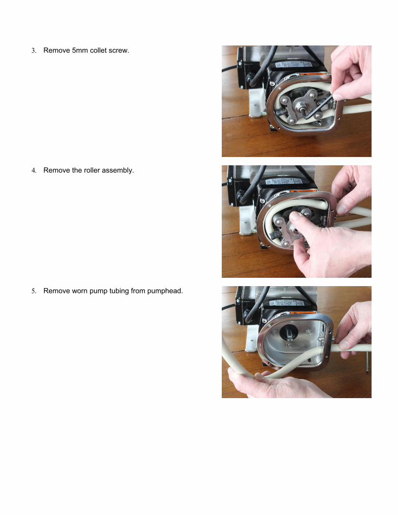
3. Remove 5mm collet screw.
4. Remove the roller assembly.
5. Remove worn pump tubing from pumphead.

6. Remove and inspect collet for wear. Note that the colletmay remain in the roller assembly when the roller assembly is removed from the pump shaft.
7. Clean inside of pump housing with damp rag or an appropriate cleaning solution to remove any chemical ortubing residue.
Reassembly:
1. Reinstall the collet onto the pump shaft.
There is a slot in the collet that the flat drive tang on the gearbox shaft must slide into. Orient the collet to allow the drive tang to slide into the slot and push the collet completely onto the gearbox shaft. When the collet bottoms out it is in the correct position.

2. Mark an 11” section of hose, which will be the portion, contained within the pump. Leave sufficient excess on the suction and discharge sides of the pump for the desired connections. If you leave the excess intake tubing in a coil near the pump it will make it easy to feed a new section of tubing through the rollers when the section in the pump becomes worn.
3. Install tubing into the pumphead.
Note: During hose installation the loop of tubing may develop a twist. Examine the hose for this condition andif needed turn one end of the hose where it exits the tubing clamp to eliminate the twist. Correctly adjusted the tubing loop will be flat and parallel to the front face of the pump housing.
Mark an 11”section of pump hose.

4. Loop tubing around roller assembly between guides as shown. Remove slack in tubing while rotating roller assembly and sliding onto collet.
5. Align marks on tubing with outside edge of the tubing clamp.
6. Reinstall collet screw firmly.
Tubing seal size varies with the selected tubing size. See tables on following pages for details
Mark an 11 inch length of tubing and locate the marks at the outside edge of the tubing seal (see arrows)
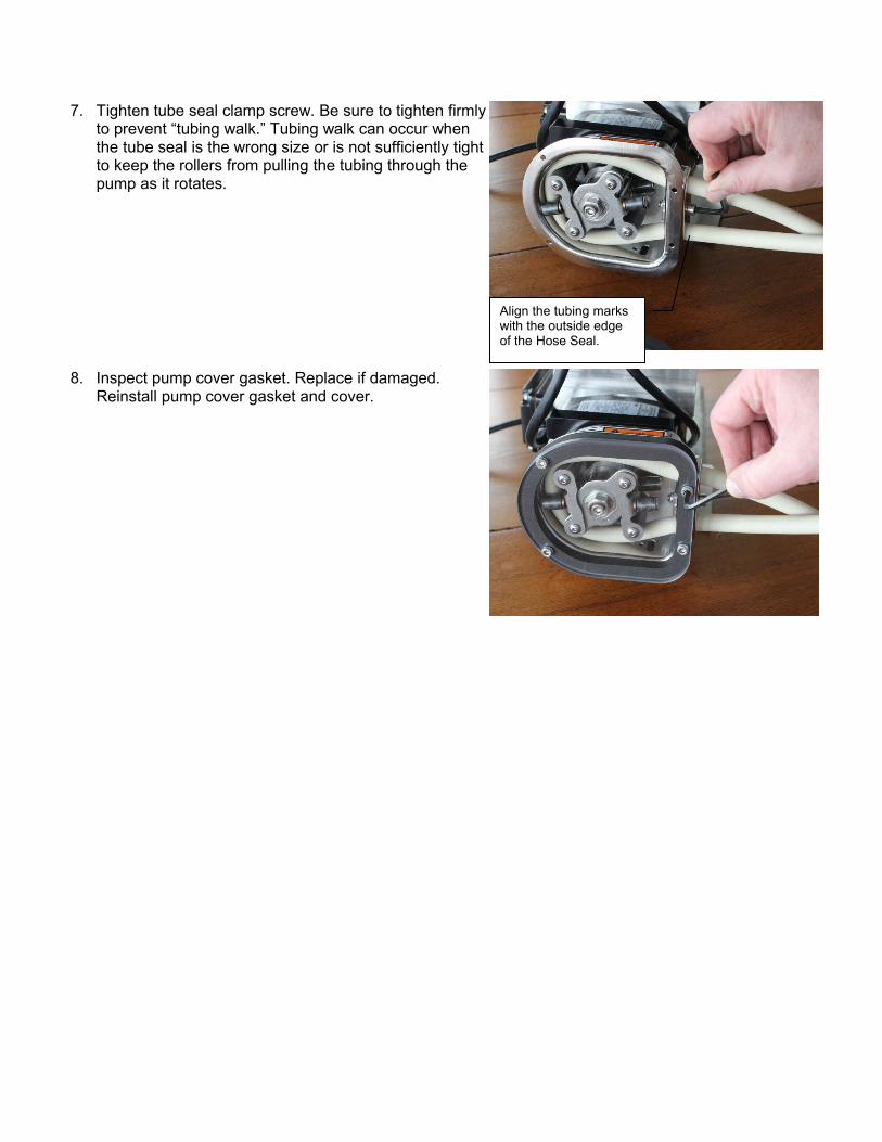
7. Tighten tube seal clamp screw. Be sure to tighten firmlyto prevent “tubing walk.” Tubing walk can occur when the tube seal is the wrong size or is not sufficiently tight to keep the rollers from pulling the tubing through the pump as it rotates.
8. Inspect pump cover gasket. Replace if damaged. Reinstall pump cover gasket and cover.
Align the tubing marks with the outside edge of the Hose Seal.

2.5 Tubing & ConnectionsTubing adapters are available for many configurations. See the drawing below for details.
2001V SERIES ESTIMATED PUMPING CAPACITY* *Actual flow rates may vary
Tubing No. #119 #120 #15 #24 #35 #36
Tubing Size 1.6mm bore(1/16”)
3.2mm bore(1/8”)
4.8mm bore(3/16”)
6.4mm bore(1/4”)
8mm bore(5/16”)
9.6mm bore(3/8”)
gph@ 0.5 – 96 rpm(V22)
0.004 – 0.7
(0.2 - 43 ml/m)
0.02 – 2.9
(0.9 - 180 ml/m)
0.03 – 6.2
(2.1 - 394 ml/m)
0.06 – 11.3
(3.7 - 710 ml/m)
0.09 – 16.7
(5.5 - 1056 ml/m)
0.11 – 21.9
(7.2 - 1382 ml/m)
gph@ 1.6 - 230 rpm(V50)
0.01 – 1.6
(0.7 - 104 ml/m)
0.05 – 6.9
(3.0 - 432 ml/m)
0.10 – 14.9
(6.6 - 943 ml/m)
0.19 – 27.0
(11.8 - 1702 ml/m)
0.28 – 40.1
(17.6 - 2530 ml/m)
0.37 – 52.5
(23.0 - 3312 ml/m)
Max Pressure (psi) 100 100 80 60 30 30
ml/rev 0.45 1.88 4.1 7.4 11 14.4
Hose Barb - PVCColor / PN
BlackHBCS2416P
GrayHBCS2432P
WhiteHBCS2448P
BlackHBCS2464P
GrayHBCS2480P
WhiteHBCS96P
Hose Barb - PTFEColor / PN
WhiteHBCS2416T
WhiteHBCS2432T
WhiteHBCS2448T
WhiteHBCS2464T
WhiteHBCS2480T
WhiteHBCS96T
Tube Seal PN 100329 100330 100331 100332 100333 100334
Pump TubingFLOPRENE
FLO.016.024 FLO.032.024 FLO.048.024 FLO.064.024 FLO.080.024 FLO.096.024
Pump TubingVITON
VIT.016.024 VIT.032.024 VIT.048.024 VIT.064.024 VIT.080.024 VIT.096.024

3.0 – 2001V Series Gearbox
3.1 Run-in PeriodThe maximum efficiency of worm reducers is obtained after a “Run-In” period. The length of time required will depend on the load applied and may be two to four hours at rated load and will be considerably longer at lighter loads. During Run-In a slightly higher than normal current and temperatures along with lower efficiency and output torque can be expected. The gear box is sealed and does not require additional lubrication.
3.2 2001V Series Motor Wiring
Motor Type: Permanent Split Capacitor or 3-Phase Inverter Duty Rotation: Reversible. Insulation: Class B minimum Finish: Powder-coat gloss black.
To reverse rotation, interchange any two line leads.

4.0 – K4 Pump Controller
4.1 Operation and Wiring
For complete details about the motor drive controller please refer to the included K4 SERIES Operating Instructions booklet.
IMPORTANT: Make sure the Mains voltage jumper is in the correct location for the supplied voltage. See the K4 drive operating instructions booklet for details.
Shown here are program settings specific to the operation with the 2001H Peristaltic Pump.
4.2 Programming
The programming differs from the factory defaults shown in the SM Vector Operating Instruction booklet only inrelation to the following parameters:
KB Default Program Settings
0.04 = 0000 GFCI disabled, enable if power pump through GFCI mains circuit (some additional noise from the drive is normal).
1.00 = 0001 Remote Start/Stop contacts enable (CHANGE TO 0000 to use 4-20 with manual start/stop)1.05 = 0003 Power fail auto restart2.00 = 0003 Freq Control Analog 2 (4-20mA)2.01 = 0001 Speed change w/o pressing enter2.02 = 0002 Enable external Local/Remote switching3.00 = 0005 Stored Set Frequency (5hz)3.02 = 0100 Upper Frequency Limit4.00 = 0000 Display in user defined units (Hz)5.00 = 0000 Enable Run Relay N.O.7.03 = 0010 Remote Start/Stop - N.O. Start7.04 = 0000 External Local/Remote Select OFF (13 for remote auto select)7.06 = 0008 External Fault input select8.00 = 0001 NC Fault Relay8.01 = 0009 Enable Status Output9.07 = 0020 4-20mA Input8.09* = 0002 When speed feedback 4-20ma output is connected
NOTES: *8.09 = 0000 to avoid fault when 4-20mA Output is disconnected when not using 4-20mA output Keypad speed can only be changed in local mode For manual speed with remote start/stop set 2.00 to 0000 For remote (4-20ma) speed with manual (keypad) start/stop set 1.00 to 0000 Large hose pumps - Boost Value 3.11 default 7, up to 12 or higher 6.05 = 1010 reset to Flomotion Defaults
4.3 To display speed in GPH: Fill a calibration cylinder (best to use water, not chemical for testing and calibration) Run the pump at full speed and time the drawdown for 30 sec. (from zero level in cylinder). Note the level in the calibration cylinder when 30 seconds has elapsed. That will be your full scale pumped flow
rate. Set menu 4.00 to 0001 (custom units). Set menu 4.01 to the GPH of the pump at full speed.

4.4 Setting the maximum pumping rate.
1. Fill a calibration cylinder (best to use water, not chemical for testing and calibration)2. Run the pump at full speed and time the drawdown for 30 sec. (from zero level in cylinder)3. Note the level in the calibration cylinder when 30 seconds elapses. That will be your full scale pumped flow rate.4. Divide the full scale pumped flow volume by the maximum hertz setting for your pump to get volume for 1HZ5. Divide the
EXAMPLE: If drawdown test is 50GPH and your maximum pump frequency is 80HZ (Upper Frequency Limit; menu 3.02) Divide 50 / 80 = 0.625 PGH @1 Hz. If desired maximum pumping rate is to be 35GPH then divide 35 / 0.625 = 56HZ. Program setting 3.02 to 56. 20mA speed control input will equal 35GPH pumping rate.

4.5 Controller Wiring Examples

5.0 - 2001 Series Tubing Rupture Detector
Rupture Detector System Overview
5.1 Alarm CausesA rupture alarm is triggered by the presence of a conductive fluid in the pump. When the fluid bridges the two stainless steel electrodes in the LIQUID SENSOR in the pump the alarm is triggered.
5.2 What to do in an alarm conditionTo clear the alarm, first stop the pump and disconnect power from the pump controller. Remove the pump cover and remove the ruptured pump tubing. Clean the inside of the pump with a soft rag. Remove any liquid or tubing debris from the inside of the pump and the area around the LIQUID SENSOR. Inspect rollers and clean if necessary.
5.3 Resuming ServiceInstall a fresh tubing insert and the pump is ready to resume service.
5.4 Resetting the alarmPress the pushbutton (Red LED leak indicator and reset switch) on the front of the Tubing Rupture Detector to reset the alarm.
! IMPORTANT: Resetting the Tubing Rupture Detector will cause the pump to resume turning !! ALWAYS reinstall the pump cover BEFORE resetting the tubing rupture detector !

Warranty
Flomotion Systems, Inc. warrants the 2001 Series pumps to be free of defects in material and workmanship for a period of eighteen months from the date of sale to the user, or two years from the date of shipment, whichever occurs first. An MC Series control, or any component contained therein, which under normal use becomesdefective within the stated warranty time period, shall be returned to Flomotion Systems, Inc., freight prepaid, for examination (contact Flomotion Systems, Inc. for authorization prior to returning any product).
Flomotion Systems, Inc. reserves the right to make the final determination as to the validity of a warranty claim, and sole obligation is to repair or replace only components, which have been rendered defective due to faulty material or workmanship. No warranty claim will be accepted for components which have been damageddue to mishandling, improper installation, unauthorized repair and/or alteration of the product, operation in excess of design specifications or other misuse, or improper maintenance.
Flomotion Systems, Inc. makes no warranty that its products are compatible with any other equipment, or to any specific application, to which they may be applied and shall not be held liable for any other consequential damage or injury arising from the use of its products. This warranty is in lieu of all other warranties, expressed or implied. No other person, firm or corporation is authorized to assume, for Flomotion Systems, Inc., any otherliability in connection with the demonstration or sale of its products.