200 Universal Controller RLU2… Basic Documentation · 2 Access levels display 3 Menu navigation 4...
128
Edition 1.0 CE1P3101en 07.07.2004 Siemens Building Technologies HVAC Products Synco 200 Universal Controller RLU2… Basic Documentation
Transcript of 200 Universal Controller RLU2… Basic Documentation · 2 Access levels display 3 Menu navigation 4...
Edition 1.0
CE1P3101en
07.07.2004
Siemens Building Technologies
HVAC Products
Synco 200
Universal Controller RLU2…
Basic Documentation

2/128
Siemens Building Technologies Universal Controller RLU2… CE1P3101en
HVAC Products 07.07.2004
Siemens Building Technologies AG
Landis & Staefa Division
Gubelstrasse 22
CH -6301 Zug
Tel. +41 41-724 24 24
Fax +41 41-724 35 22
www.landisstaefa.com
© 2004 Siemens Building Technologies AG
Subject to alteration
3/128
Siemens Building Technologies Universal Controller RLU2… CE1P3101en
HVAC Products Contents 07.07.2004
Contents
1 Summary ........................................................................................................5
1.1 Range of units .................................................................................................5
1.2 Equipment combinations .................................................................................5
1.3 Product documentation....................................................................................6
1.4 Functions .........................................................................................................7
1.5 Important notes................................................................................................8
2 Operation........................................................................................................9
2.1 Operating elements and display ......................................................................9
2.2 Operating and access levels .........................................................................11
2.3 Menu..............................................................................................................13
3 Commissioning............................................................................................15
3.1 Safety ............................................................................................................15
3.2 Entering commissioning mode ......................................................................15
3.3 Choosing the basic configuration ..................................................................16
3.4 Three ways to get the right application..........................................................17
3.5 Performing a wiring test.................................................................................17
3.6 Leaving commissioning mode .......................................................................18
4 General settings ..........................................................................................19
4.1 Choosing units...............................................................................................19
4.2 Device information.........................................................................................19
5 Operating modes .........................................................................................20
5.1 Basic types ....................................................................................................20
5.2 Room mode selection via digital inputs .........................................................20
5.3 Fan release....................................................................................................22
6 Inputs............................................................................................................23
6.1 Universal inputs X1…X5................................................................................23
6.2 Analog inputs X1…X5 ...................................................................................24
6.3 Digital inputs (D1, D2, X1…X5) .....................................................................28
6.4 Absolute remote setpoint (REM) ...................................................................29
6.5 Relative remote setpoint (REL) .....................................................................31
6.6 Outside temperature (OUTS) ........................................................................33
6.7 Room temperature (ROOM) ..........................................................................34
7 Aggregates...................................................................................................35
7.1 Pump (PUMP x).............................................................................................35
7.2 Modulating output (AO x)...............................................................................38
7.3 Heat recovery equipment /mixed air damper (HREC) ...................................40
7.4 Variable step switch (STEP Vx).....................................................................49
7.5 Linear step switch (STEPLIN) .......................................................................52
4/128
Siemens Building Technologies Universal Controller RLU2… CE1P3101en
HVAC Products Contents 07.07.2004
7.6 Binary step switch (STEPBIN) .......................................................................56
7.7 3-position output (3-POINT)...........................................................................60
8 Controller (CTLOOP x) ................................................................................62
8.1 General ..........................................................................................................62
8.2 Control strategies and setpoints ....................................................................63
8.3 Room temperature control .............................................................................65
8.4 Room/supply air temperature cascade controller..........................................66
8.5 Supply air temperature control.......................................................................70
8.6 Universal controller ........................................................................................72
8.7 Primary controller (universal) with changeover..............................................75
8.8 Sequence controllers, output assignments ....................................................79
8.9 Limit control, general (LIM) ............................................................................84
8.10 Limit control of individual sequences (SEQ) ..................................................86
8.11 Locking of sequences according to outside temperature...............................89
8.12 Summer/winter compensation.......................................................................90
8.13 Universal setpoint shift...................................................................................91
8.14 Deviation message (DV ALM)........................................................................93
9 Frost protection (FROST)............................................................................95
9.1 Purpose and types of monitoring ...................................................................95
9.2 Activating the function block ..........................................................................95
9.3 Settings ..........................................................................................................96
9.4 Operating principle.........................................................................................96
9.5 Acknowledgement / reset (AKN)....................................................................99
9.6 Display indication ...........................................................................................99
9.7 Connection diagrams...................................................................................100
9.8 Error handling ..............................................................................................101
9.9 Settings ........................................................................................................101
10 Dealing with alarms ...................................................................................102
10.1 Alarm list ......................................................................................................102
10.2 Troubleshooting ...........................................................................................103
11 Electrical connections...............................................................................104
11.1 Connection rules ..........................................................................................104
11.2 Connection terminals ...................................................................................105
12 Appendix.....................................................................................................106
12.1 Abbreviations used ......................................................................................106
12.2 Synco 200 operating texts ...........................................................................107
12.3 Configuration................................................................................................111
13 Application examples ................................................................................124

5/128
Siemens Building Technologies Universal Controller RLU2… CE1P3101en
HVAC Products 1 Summary 07.07.2004
1 Summary
1.1 Range of units
The following table lists the controller types and accessories belonging to the product
range, and indicates the respective datasheets:
Device Name Type Data Sheet no.
Controllers Universal controller RLU210 N3101
Universal controller RLU222 N3101
Universal controller RLU232 N3101
Universal controller RLU236 N3101
Service unit Service tool OCI700.1 N5655
Installation accessories Front panel mounting frame ARG62.201 N3101
The following pictures show the controller versions with large and small housing
variants:
RLU232 and RLU236 RLU210 and RLU222
1.2 Equipment combinations
The following table lists the equipment that is combinable with the above controllers:
Device Type Datasheet no.
Passive sensors All types of sensors using a sensing
element
LG-Ni 1000, Pt 1000 or T1 (PTC)
N1721…N1846,
N1713
Active sensors All types of sensors with
Operating voltage AC 24 V
Modulating DC 0…10 V output signal
N1821, N1850…N1932
Monitors QAF81..., QAF64...,
QFA81, QFM81,
QFX21, QXA2000,
QBM81...
N1284, N1283,
N1513, N1514,
N1541, N1542
N1552
Signal converter SEZ220 N5146
Room units QAA25, QAA27 N1721
Passive signal
sources
BSG21.1, BSG21.5,
QAA25, QAA27
N1991,
N1721
Active signal
sources
BSG61 N1992
Actuating devices All types of electromotoric and
electrohydraulic actuators:
operating on AC 24 V
for modulating control DC 0..10 V
For detailed information on actuators
and valves, refer to: N4000…N4999
Controller types and
accessories
Housing variants
Possible combinations
6/128
Siemens Building Technologies Universal Controller RLU2… CE1P3101en
HVAC Products 1 Summary 07.07.2004
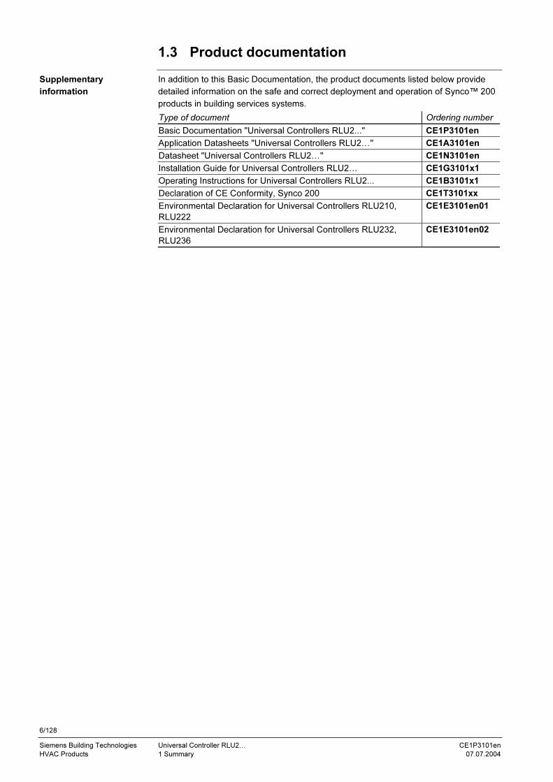
1.3 Product documentation
In addition to this Basic Documentation, the product documents listed below provide
detailed information on the safe and correct deployment and operation of Synco™ 200
products in building services systems.
Type of document Ordering number
Basic Documentation "Universal Controllers RLU2..." CE1P3101en
Application Datasheets "Universal Controllers RLU2…" CE1A3101en
Datasheet "Universal Controllers RLU2…" CE1N3101en
Installation Guide for Universal Controllers RLU2… CE1G3101x1
Operating Instructions for Universal Controllers RLU2... CE1B3101x1
Declaration of CE Conformity, Synco 200 CE1T3101xx
Environmental Declaration for Universal Controllers RLU210,
RLU222
CE1E3101en01
Environmental Declaration for Universal Controllers RLU232,
RLU236
CE1E3101en02
Supplementary
information

7/128
Siemens Building Technologies Universal Controller RLU2… CE1P3101en
HVAC Products 1 Summary 07.07.2004
1.4 Functions
The following table provides an overview of the functions available with the various
controller types:
Function RLU210 RLU222 RLU232 RLU236
Number of preloaded applications 19 40 21 27
Basic types
Basic type A
Basic type U
Selection of operation
ON/OFF via digital inputs
Mode selection via digital inputs
Changeover (A, U) (U) (U) (U)
Interaction with heating controller
Alarms
Indicating relay, frost and primary controlled
variable
0
Indicating relay, deviation indication 0
Digital inputs 1 1 2 2
Universal inputs 3 4 5 5
Analog inputs DC 0…10 V
Analog inputs LG-Ni 1000
Analog inputs T1
Analog inputs PT 1000
Digital inputs
Remote setpoints (absolute and relative)
Modulating outputs DC 0…10 V 1 2 3 3
Relay outputs 0 2 2 6
Pump 0 2 2 3
Analog output 1 2 3 3
Heat recovery unit / damper 1 1 1 1
Variable step switch (1-6 steps) 0 0 0 1
Variable step switch (1-2 steps) 0 1 1 1
Linear step switch (1-6 steps) 0 0 0 1
Linear step switch (1-2 steps) 0 0 1 0
Binary step switch (1-4 steps) 0 0 0 1
Binary step switch (1-2 steps) 0 0 1 0
3-position output 0 1 0 0
Universal controller \\_// 0 1 1 1
Universal controller \_/ 1 0 1 1
Room / supply air cascade controller 1 1 1 1
Remote setpoint adjuster 1 1 1 1
Setpoint shift via room unit 1 1 1 1
Setpoint shift based on outside temperature 1 1 1 1
Universal setpoint shift 1 1 1 1
Limit control, general 1 1 1 1
Limit control of individual sequences 1 1 1 1
Locking of sequences 2 4 6 6
Frost protection
Frost protection unit
2-stage frost protection on the air side
2-stage frost protection on the water side
Fan enable RELEASE 0 1 1 1
Overview

8/128
Siemens Building Technologies Universal Controller RLU2… CE1P3101en
HVAC Products 1 Summary 07.07.2004
1.5 Important notes
This symbol draws your attention to special safety notes and warnings. If such notes
are not observed, personal injury and / or considerable damage to property can occur.
Synco™ 200 products may only be used for the control and supervision of heating,
ventilation, air conditioning and chilled water plant.
Prerequisites for flawless and safe operation of Synco™ 200 products are proper
transport, installation, commissioning, and correct operation.
Fuses, switches, wiring and earthing must be in compliance with local safety
regulations for electrical installations.
Preparation for use and commissioning of Synco™ 200 products must be undertaken
by qualified staff who have been appropriately trained by Siemens Building
Technologies.
Synco™ 200 products may only be operated by staff who have been instructed by
Siemens Building Technologies or their delegates and whose attention has been drawn
to potential risks.
When wiring the system, the AC 230 V section must be strictly segregated from the
AC 24 V safety extra low-voltage (SELV) section in order to ensure protection against
electric shock hazard!
For storage and transport, the limits given in the relevant datasheets must always be
observed.
If in doubt, contact your supplier or Siemens Building Technologies.
Synco™ 200 products are maintenance-free, apart from cleaning at regular intervals.
System sections accommodated in the control panel should be freed from dust and dirt
whenever normal service visits are due.
If system faults occur and you are not authorized to perform diagnostics and rectify
faults, call your Siemens Building Technologies service representative.
Only authorized staff are permitted to perform diagnostics, to rectify faults and to restart
the plant. This also applies to work carried out within the control panel (e.g. safety
checks or changing fuses).
The products contain electrical and electronic components and may not be disposed of
as household waste.
Current local legislation must be observed.
Field of use
Correct use
Electrical installation
Commissioning
Operation
Wiring
Storage and transport
Maintenance
faults
Disposal
9/128
Siemens Building Technologies Universal Controller RLU2… CE1P3101en
HVAC Products 2 Operation 07.07.2004
2 Operation
2.1 Operating elements and display
2.1.1 Operating elements
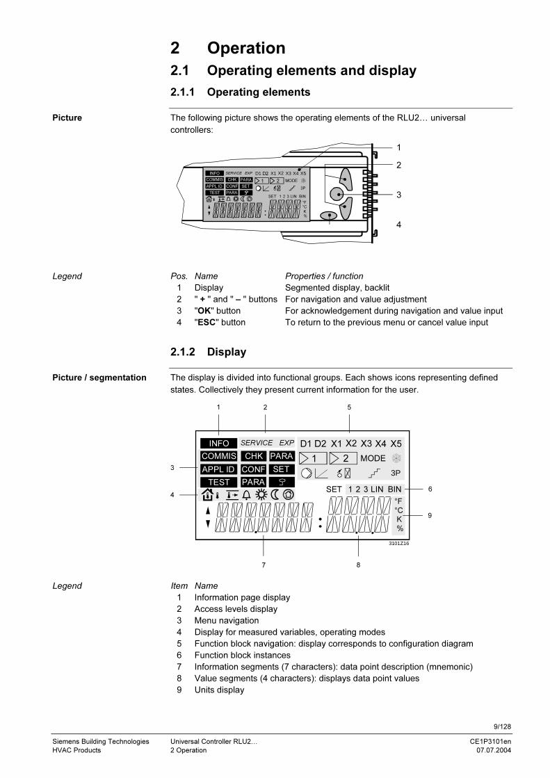
The following picture shows the operating elements of the RLU2… universal
controllers:
1
2
3
4
Pos. Name Properties / function
1 Display Segmented display, backlit
2 " + " and " – " buttons For navigation and value adjustment
3 "OK" button For acknowledgement during navigation and value input
4 "ESC" button To return to the previous menu or cancel value input
2.1.2 Display
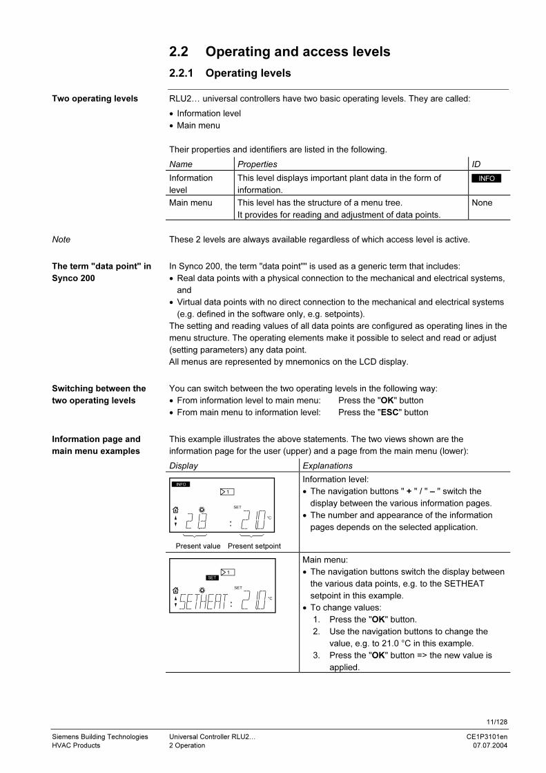
The display is divided into functional groups. Each shows icons representing defined
states. Collectively they present current information for the user.
LIN BIN1 2 3
°F
°C
K
%
INFO
COMMIS
APPL ID
TEST
CHK
SET
SERVICE EXP
PARA
SET
PARA
CONF
X5D1 D2
1
X1 X2
2
X3 X4
MODE
3P
1 2 5
6
9
87
4
3
3101Z16
Item Name
1 Information page display
2 Access levels display
3 Menu navigation
4 Display for measured variables, operating modes
5 Function block navigation: display corresponds to configuration diagram
6 Function block instances
7 Information segments (7 characters): data point description (mnemonic)
8 Value segments (4 characters): displays data point values
9 Units display
Picture
Legend
Picture / segmentation
Legend
LIN BIN1 2 3
°F
°C
K
%
INFO
COMMIS
APPL ID
TEST
CHK
SET
SERVICE EXP
PARA
SET
PARA
CONF
X5D1 D2
1
X1 X2
2
X3 X4
MODE
3P

10/128
Siemens Building Technologies Universal Controller RLU2… CE1P3101en
HVAC Products 2 Operation 07.07.2004
2.1.3 Display icons
The following table shows the icons used on the display with their meanings. They are
grouped according to the segmentation shown in the above.
Icon Meaning Icon Meaning
Operating level Function block navigation
INFO Information level D1, D2 Digital input D1, D2
None Setting level X1…X5 Analog input X1…X5
Access level 1 Controller 1 (or controller 2)
SERVICE Service level MODE Operating mode
EXP Password level Frost protection FB
Menus Pump FB
COMMIS Commissioning Analog output FB
APPL ID Basic type Heat recovery FB
TEST Wiring test Step switch FB
CHK Inputs / outputs 3P 3-position output FB
CONF Configuration Instances
PARA Parameter settings 1 Instance 1
SET Setpoints, adjustable 2 Instance 2
Measured variables, operating modes 3 Instance 3
Outside temperature LIN Linear step switch
Room temperature BIN Binary step switch
Supply air temperature Units
Fault F Degrees Fahrenheit
Room operating mode
”Comfort”
°C Degrees Celsius
Room operating mode
"Economy”
K Kelvin
Protection mode % Percent
Navigation Miscellaneous
Navigation UP or value + SET Adjustable value
Navigation DOWN or value –
The user level is activated if neither the icon for the service level nor the icon for the
password level is visible.
Table of icons used
Note on access levels
11/128
Siemens Building Technologies Universal Controller RLU2… CE1P3101en
HVAC Products 2 Operation 07.07.2004
2.2 Operating and access levels
2.2.1 Operating levels
RLU2… universal controllers have two basic operating levels. They are called:
• Information level
• Main menu
Their properties and identifiers are listed in the following.
Name Properties ID
Information
level
This level displays important plant data in the form of
information.
INFO
Main menu This level has the structure of a menu tree.
It provides for reading and adjustment of data points.
None
These 2 levels are always available regardless of which access level is active.
In Synco 200, the term "data point"" is used as a generic term that includes:
• Real data points with a physical connection to the mechanical and electrical systems,
and
• Virtual data points with no direct connection to the mechanical and electrical systems
(e.g. defined in the software only, e.g. setpoints).
The setting and reading values of all data points are configured as operating lines in the
menu structure. The operating elements make it possible to select and read or adjust
(setting parameters) any data point.
All menus are represented by mnemonics on the LCD display.
You can switch between the two operating levels in the following way:
• From information level to main menu: Press the "OK" button
• From main menu to information level: Press the "ESC" button
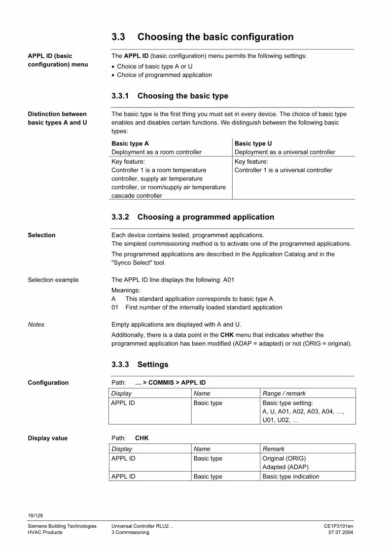
This example illustrates the above statements. The two views shown are the
information page for the user (upper) and a page from the main menu (lower):
Display Explanations
°C
INFO
SET
1
Present value Present setpoint
Information level:
• The navigation buttons " + " / " – " switch the
display between the various information pages.
• The number and appearance of the information
pages depends on the selected application.
°C
SET
SET
1
Main menu:
• The navigation buttons switch the display between
the various data points, e.g. to the SETHEAT
setpoint in this example.
• To change values:
1. Press the "OK" button.
2. Use the navigation buttons to change the
value, e.g. to 21.0 °C in this example.
3. Press the "OK" button => the new value is
applied.
Two operating levels
Note
The term "data point" in
Synco 200
Switching between the
two operating levels
Information page and
main menu examples

12/128
Siemens Building Technologies Universal Controller RLU2… CE1P3101en
HVAC Products 2 Operation 07.07.2004
2.2.2 Access levels
RLU2… universal controllers have three access levels. They are called:
• User level
• Service level
• Password level
One of these access levels is associated with each data point.
The following table lists the three access levels with their respective purpose,
accessibility and icon:
Level Access Icon
User level
(for the plant
operator)
The user level is always accessible.
Users can modify all data points that are
visible/adjustable at this level.
None
Service level
(for maintenance)
1. Simultaneously press the "OK" and "ESC"
buttons.
2. Use the " + " / " – " buttons to choose the
service level SERV.
3. Press the "OK" button to confirm your choice.
SERVICE
Password level
(for commissioning)
1. Simultaneously press the "OK" and "ESC"
buttons.
2. Use the " + " / " – " buttons to choose the
password level EXP.
3. Press the "OK" button to confirm your choice.
4. When PASSWRD is displayed, select the
figure 2 using the " + " button.
5. Press the "OK" button to confirm your choice.
EXP
The three access levels have the following properties in common:
• The access level determines which individual menus and operating lines are enabled.
• At a higher access level, all of the menus and operating lines of the lower access
levels remain visible.
• The levels are all based on a common menu tree. The entire menu tree is available at
password level.
• The controller returns to the user level after a 30-minute timeout. Timeout: period
without user input at the controller.
The three access levels
Access
Common properties

13/128
Siemens Building Technologies Universal Controller RLU2… CE1P3101en
HVAC Products 2 Operation 07.07.2004
2.3 Menu
2.3.1 Menu structure
The controller shows or hides the respective submenus according to the selected
access level:
User level Service level Password level
Information level
Info displays 1…n
Information level
Info displays 1…n
Information level
Info displays 1…n
↓ OK
ESC ↑
↓ OK
ESC ↑
↓ OK
ESC ↑
Main menu
SET (setpoints)
Main menu
CHK (inputs / outputs)
PARA (settings)
SET (setpoints)
Main menu
COMMIS (commissioning)
| APPL ID (basic
configuration)
| CONF (extra configuration)
| TEST (wiring test)
| PARA (settings)
CHK (inputs / outputs)
PARA (settings)
SET (setpoints)
At the user level, the "OK" button switches the menu directly to the SET (setpoint) list,
where you can use the " + " (UP) and " – " (DOWN) buttons to choose and adjust a
setpoint.
Levels and menus
Notes on the user level

14/128
Siemens Building Technologies Universal Controller RLU2… CE1P3101en
HVAC Products 2 Operation 07.07.2004
2.3.2 Menu navigation
The following pictures demonstrate menu navigation with the example of adjusting
proportional band Xp for sequence 1 of control loop 1. The access level is already set
to SERVICE.
Starting point: Information level
Step Display Procedure / results
1 CHK
SERVICE
PARA
SET
1. Press the "OK" button:
=> the first menu item starts to flash,
in this case CHK (inputs / outputs)
Note: The information segments
present explanatory texts about the
menu (here: VALUES).
2 CHK
SERVICE
PARA
SET
1. Use the " – " button to navigate to
the PARA (settings) menu item:
=> PARA starts to flash.
2. Confirm your choice with the "OK"
button.
3 SERVICE
PARA
X5
1
X1 X2
2
X3 X4
MODE
3P
The controller displays the function
block selection with the first function
block (X1) flashing.
4 SERVICE
PARA
X5
1
X1 X2
2
X3 X4
MODE
3P
1. Use the " – " button to navigate to
the CTLOOP 1 menu item.
2. Confirm your choice with the "OK"
button.
5
SET
SERVICE
PARA 1
K
The controller displays the parameter
selection (see information segments,
bottom left).
1. Use the " + " / " – " buttons to
navigate to the parameter of your
choice (SEQ1 XP), then press the
"OK" button:
=> the corresponding value starts to
flash (30.0)
2. Use the " + " / " – " buttons to adjust
the value, and confirm the new value
with the "OK" button.
Example

15/128
Siemens Building Technologies Universal Controller RLU2… CE1P3101en
HVAC Products 3 Commissioning 07.07.2004
3 Commissioning
3.1 Safety
Preparation for use and commissioning of Synco™ 200 controllers must only be
undertaken by qualified staff who have been appropriately trained by Siemens
Building Technologies.
3.2 Entering commissioning mode
3.2.1 Entry on first startup
The controller automatically enters the commissioning menu when the AC 24 V power
supply is applied. Please note the following:
• The control process remains deactivated in the commissioning mode – all outputs are
set to a defined OFF state on controller power-up.
• All of the controller's internal safety features are also deactivated!
The controller displays these settings as soon as it is powered up:
• EXP access level (password level)
• COMMIS (commissioning) menu with the APPL ID (basic configuration) submenu
flashing.
COMMIS
APPL ID
TEST
EXP
PARA
CONF
3.2.2 Entry from the main menu
The COMMIS (commissioning) menu is only active at password level (password = 2). If
the password level is not already selected, simultaneously press the "ESC" and "OK"
buttons activate it.
When a user enters the commissioning menu from the main menu, the controller
indicates that the plant will be stopped:
COMMIS
EXP
Pressing the "OK" button produces the following results:
• The controller stops the plant and deactivates the control process.
• It sets all outputs to a defined OFF state.
• It also deactivates all of the controller's internal safety features!
• The controller displays the submenus of the COMMIS (commissioning) menu with the
first one, APPL ID (basic configuration), flashing; refer to the picture under "factory
settings" in the above.
Procedure
Factory settings
Prerequisite
Plant is stopped
16/128
Siemens Building Technologies Universal Controller RLU2… CE1P3101en
HVAC Products 3 Commissioning 07.07.2004
3.3 Choosing the basic configuration
The APPL ID (basic configuration) menu permits the following settings:
• Choice of basic type A or U
• Choice of programmed application
3.3.1 Choosing the basic type
The basic type is the first thing you must set in every device. The choice of basic type
enables and disables certain functions. We distinguish between the following basic
types:
Basic type A
Deployment as a room controller
Basic type U
Deployment as a universal controller
Key feature:
Controller 1 is a room temperature
controller, supply air temperature
controller, or room/supply air temperature
cascade controller
Key feature:
Controller 1 is a universal controller
3.3.2 Choosing a programmed application
Each device contains tested, programmed applications.
The simplest commissioning method is to activate one of the programmed applications.
The programmed applications are described in the Application Catalog and in the
"Synco Select" tool.
The APPL ID line displays the following: A01
Meanings:
A This standard application corresponds to basic type A.
01 First number of the internally loaded standard application
Empty applications are displayed with A and U.
Additionally, there is a data point in the CHK menu that indicates whether the
programmed application has been modified (ADAP = adapted) or not (ORIG = original).
3.3.3 Settings
Path: … > COMMIS > APPL ID
Display Name Range / remark
APPL ID Basic type Basic type setting:
A, U, A01, A02, A03, A04, …,
U01, U02, …
Path: CHK
Display Name Remark
APPL ID Basic type Original (ORIG)
Adapted (ADAP)
APPL ID Basic type Basic type indication
APPL ID (basic
configuration) menu
Distinction between
basic types A and U
Selection
Selection example
Notes
Configuration
Display value

17/128
Siemens Building Technologies Universal Controller RLU2… CE1P3101en
HVAC Products 3 Commissioning 07.07.2004
3.4 Three ways to get the right application
3.4.1 Programmed application
Each universal controller contains a large number of tested, programmed applications.
The simplest commissioning method is to activate one of the programmed applications
and, if necessary, adjust the parameters to reflect the actual plant.
The programmed applications are described in the Application Catalog or in the "Synco
Select" tool.
3.4.2 Adapted application
The programmed application doesn't quite fit, but an adapted application is described in
the Application Catalog. Make the appropriate settings in the CONF (extra
configuration) menu in order to adapt the application.
3.4.3 Free configuration
The application you want is not described; you have to set up the configuration from
scratch. You can adapt the controller to the plant using the configuration diagrams (see
chapter 12.3, Configuration).
3.5 Performing a wiring test
When the peripheral equipment is connected, you can perform a wiring test in the
TEST (wiring test) menu. We recommend performing the test after completion of the
configuration and settings. It provides the following functions:
• Indication of input reading values
• ON/OFF switching of the aggregates connected to the outputs, such as pumps
• Specification of a 0…100 % signal for step switches, where the relay is switched
The application is deactivated during the wiring test. The outputs are in a defined "OFF"
state, and safety-related functions (e.g. frost protection) are deactivated!
The wiring test provides checks for the following errors at the inputs and outputs:
• Connection errors, i.e. reversed wires
• Position errors, i.e. sensors or actuators connected in the wrong place
• Discrepancies between connection method and controller configuration, LG-Ni 1000
instead of active DC 0…10 V
The simplest way
The happy medium
The most costly way
Functions
Error checks

18/128
Siemens Building Technologies Universal Controller RLU2… CE1P3101en
HVAC Products 3 Commissioning 07.07.2004
3.6 Leaving commissioning mode
When you leave the COMMIS (commissioning) menu by pressing the ESC button, the
controller displays the following information to indicate that the plant will be started:
COMMIS
EXP
Pressing the "OK" button produces the following results:
• The application starts,
− the controller checks all sensors, and
− it tags the existing sensors for later fault messages
• The display switches to the next-higher menu level, and the COMMIS menu icon
starts to flash:
CHK
EXP
PARA
SET
COMMIS
Now press the "ESC" button twice.
The controller will display an information page like the following if it is in normal mode:
INFO EXP
User information
Plant starts
Exit

19/128
Siemens Building Technologies Universal Controller RLU2… CE1P3101en
HVAC Products 4 General settings 07.07.2004
4 General settings
4.1 Choosing units
At the service and password levels, you can switch the temperature unit between °C/K
and °F:
Path: … > PARA > MODE
Display Name Range Factory setting
UNIT Unit °C, °F °C
4.2 Device information
You can view the SW version at the service and password levels:
Path: CHK
Display Name Remarks
SW-VERS Software version
Setting values
Display values
20/128
Siemens Building Technologies Universal Controller RLU2… CE1P3101en
HVAC Products 5 Operating modes 07.07.2004
5 Operating modes
5.1 Basic types
We distinguish between the following two basic applications in the RLU2.. universal
controllers:
• Basic type A => controller 1 is a room temperature controller
• Basic type U => controller 1 is a universal controller
In normal operation, the operating mode for basic types A and U is preselectable via
digital inputs D1 / D2 (e.g. by an external scheduler or manual switch).
There are the following three operating modes:
• Comfort
• Economy
• Protection
5.2 Room mode selection via digital inputs
This feature provides for intervention in the current program without having to make any
changes at the controller itself. In order to activate this function, you have to configure
the appropriate digital inputs.
Mode switching via HMI (operation) is not possible.
The following settings are required depending on the desired function:
Function Setting Value
Switch between
comfort / protection
Digital input D1, hard
wired
Permanently configured
Switch between
comfort / economy
Digital input D2, hard
wired
Permanently configured
D1 D2 Operating mode Function
0 0 Comfort "Comfort" is the operating mode for the
occupied room. The room state is within the
comfort envelope in terms of temperature,
humidity, etc.
0 1 Economy "Economy" is an energy-saving operating mode
for the room if "comfort" mode is not required
for a given period. In "economy" mode, the
control process operates with setpoints that
may differ from the "comfort" mode setpoints.
Switchover to "economy" mode is usually done
via an external scheduler.
1 0 Protection "Protection" is an operating mode in which a
plant is only started to ensure that the building
and equipment are protected against frost.
1 1 Protection See above
• If there is no wire connected to digital input D1, then D1 = 0.
• If digital input D1 is set to protection, "comfort" / "economy" switchover is deactivated.
The following settings are required depending on the desired function:
Function Setting Value
Switch between Digital input D1, hard wired Permanently
Basic applications
Operating modes
Operating principle
Note
RLU232 and RLU236
Notes
RLU210 and RLU222

21/128
Siemens Building Technologies Universal Controller RLU2… CE1P3101en
HVAC Products 5 Operating modes 07.07.2004
comfort / protection configured
Switch between
comfort / economy
Digital input configured for
OPMODE
X1…X5
D1 OP MODE Operating mode Function
0 0 Comfort See "RLU232 and RLU236"
0 1 Economy See "RLU232 and RLU236"
1 0 Protection See "RLU232 and RLU236"
1 1 Protection See "RLU232 and RLU236"
If no other digital input is configured as OPMODE (preselected optg mode input), you
can configure the switchover between "comfort" / "protection " (default) or "comfort" /
"economy" with the hard wired D1 input via parameter settings as an additional
function.
Errors in operation:
The digital signals cannot be monitored. The controller interprets missing inputs as if
the physical input is not connected.
We recommend configuring the control inputs to be open in the normal position
(NORMPOS = OPEN).
Configuration errors:
Applying analog signals (e.g. DC 0 …10 V or LG-Ni 1000) to the digital control inputs
produces an incorrect response that is not monitored.
You can use the digital inputs to switch a plant to "OFF". However, all safety-related
functions remain active.
Note
Error handling
Application example

22/128
Siemens Building Technologies Universal Controller RLU2… CE1P3101en
HVAC Products 5 Operating modes 07.07.2004
5.3 Fan release
This function uses the RLU2… controller's Q1 switch output to enable the fan.
The fan is always enabled if:
• There is no "FROST" signal
• There is no "MAINALM" fault on the main control variable
• The COMMIS (commissioning) menu is not active at the controller
Use the switch output as a changeover switch, where:
• Switch output de-energized => fault signal (frost or main control variable error)
• Switch output energized => fan enabled
The following example shows the connection on an RLU232 unit:
L
G
G
G0
M X... Q11
Q14
G0
N
N1
K1
3101A06
AC
230
V
AC
24 V
G0 G1 Y1
Q33
Q34
D2M
Q12
D1
S7
M
H1
Q11, Q12, Q14: Terminals of switch output Q1
K1: Fan relay H1: Alarm indicator
To activate the fan release function, assign relay Q1 to the appropriate output signal
under RELEASE (fan release relay) in the MODE submenu.
5.3.1 Settings
Path: … > COMMIS > CONF > MODE
Display Name Range / remark
RELEASE Fan release relay Activates the relay output; adjustable values:
---,Q1, Q2, … (free outputs only)
Path: CHK
Display Name Remarks
RELEASE Fan release relay YES = fan enabled (relay energized)
NO = alarm (relay de-energized)
Path: … > COMMIS > TEST
Display Name Positions
RELEASE Fan release relay YES = fan enabled (relay energized)
NO = alarm (relay de-energized)
Function and conditions
Recommendation
Connection diagram
Legend
Activating the function
Configuration
Display values
Wiring test
23/128
Siemens Building Technologies Universal Controller RLU2… CE1P3101en
HVAC Products 6 Inputs 07.07.2004
6 Inputs
6.1 Universal inputs X1…X5
6.1.1 General settings
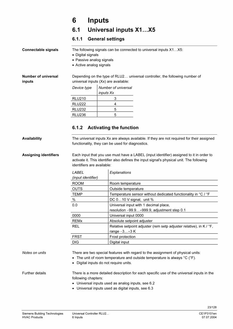
The following signals can be connected to universal inputs X1…X5:
• Digital signals
• Passive analog signals
• Active analog signals
Depending on the type of RLU2… universal controller, the following number of
universal inputs (Xx) are available:
Device type Number of universal
inputs Xx
RLU210 3
RLU222 4
RLU232 5
RLU236 5
6.1.2 Activating the function
The universal inputs Xx are always available. If they are not required for their assigned
functionality, they can be used for diagnostics.
Each input that you use must have a LABEL (input identifier) assigned to it in order to
activate it. This identifier also defines the input signal's physical unit. The following
identifiers are available:
LABEL
(input identifier)
Explanations
ROOM Room temperature
OUTS Outside temperature
TEMP Temperature sensor without dedicated functionality in °C / °F
% DC 0…10 V signal, unit %
0.0 Universal input with 1 decimal place,
resolution −99.9…+999.9, adjustment step 0.1
0000 Universal input 0000
REMx Absolute setpoint adjuster
REL Relative setpoint adjuster (rem setp adjuster relative), in K / °F,
range −3…+3 K
FRST Frost protection
DIG Digital input
There are two special features with regard to the assignment of physical units:
• The unit of room temperature and outside temperature is always °C (°F).
• Digital inputs do not require units.
There is a more detailed description for each specific use of the universal inputs in the
following chapters:
• Universal inputs used as analog inputs, see 6.2
• Universal inputs used as digital inputs, see 6.3
Connectable signals
Number of universal
inputs
Availability
Assigning identifiers
Notes on units
Further details

24/128
Siemens Building Technologies Universal Controller RLU2… CE1P3101en
HVAC Products 6 Inputs 07.07.2004
6.2 Analog inputs X1…X5
6.2.1 Activation and type
To activate the analog inputs X1…X5, follow the procedure described under "activating
the function" in the above.
If the unit is °C / °F, the type is selectable. The following types are available:
• NI (LG-Ni 1000)
• 2XNI (2 x LG-Ni 1000)
• T1 (T1)
• PT (Pt 1000)
• 0-10 (DC 0…10 V)
If the unit is not °C / °F, the type is always DC 0…10 V.
6.2.2 Measuring range (MIN VAL, MAX VAL)
The following measuring ranges are defined for passive temperature signals:
Temperature signal Measuring range
LG-Ni 1000 –50…+250 °C (fixed)
2 x LG-Ni 1000 or T1 –50…+150 °C (fixed)
Pt 1000 –50…+400 °C (fixed)
In the case of active signals, the measuring range is definable. Both an upper and a
lower measured value is required.
Active DC 0…10 V temperature signals have a default measuring range of 0…200 °C,
but they are adjustable within the overall range of –50…+500 °C.
Room temperature with an active signal of DC 0…10 V = 0…50 °C:
− Lower measured value (MIN VAL):0 °C
− Upper measured value (MAX VAL):50 °C
6.2.3 Active measured value signal (SIGNALY)
The controller can also signalize measured values from passive sensors in the form of
active, modulating signals. In order to achieve this, you must assign an output to the
input signal. The settings under "measuring range" are also used for setting up the
output.
You want to signalize the measured value from an LG-Ni 1000 sensor as an active
signal of DC 0…10 V = 0…50 °C:
− Lower measured value (MIN VAL): 0 °C
− Upper measured value (MAX VAL): 50 °C
The active measuring signal is only usable for analog values.
Digital signals would produce an output of either DC 0 V or DC 10 V.
Activation
Type (TYPE)
Passive temperature
signals
Active signals
Example
Multiple sensor use
Example
Note
25/128
Siemens Building Technologies Universal Controller RLU2… CE1P3101en
HVAC Products 6 Inputs 07.07.2004
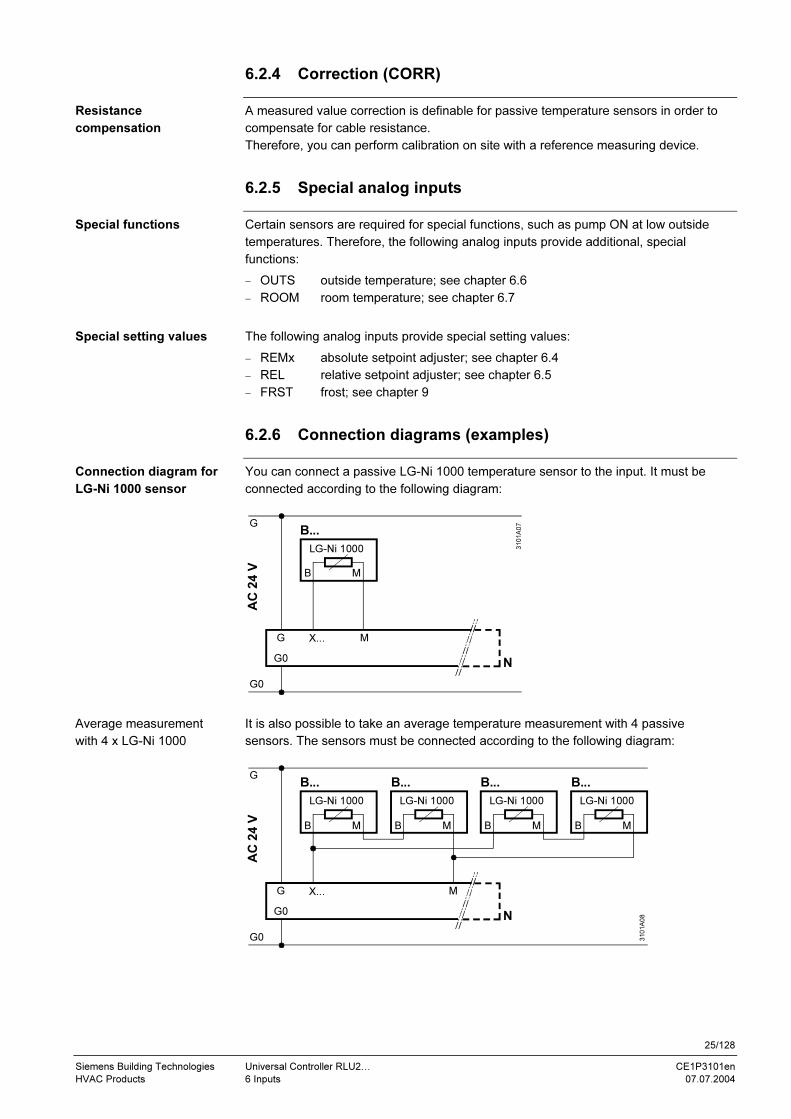
6.2.4 Correction (CORR)
A measured value correction is definable for passive temperature sensors in order to
compensate for cable resistance.
Therefore, you can perform calibration on site with a reference measuring device.
6.2.5 Special analog inputs
Certain sensors are required for special functions, such as pump ON at low outside
temperatures. Therefore, the following analog inputs provide additional, special
functions:
− OUTS outside temperature; see chapter 6.6
− ROOM room temperature; see chapter 6.7
The following analog inputs provide special setting values:
− REMx absolute setpoint adjuster; see chapter 6.4
− REL relative setpoint adjuster; see chapter 6.5
− FRST frost; see chapter 9
6.2.6 Connection diagrams (examples)
You can connect a passive LG-Ni 1000 temperature sensor to the input. It must be
connected according to the following diagram:
G
G
G0
X... M
G0
B...
N
3101A07
AC
24 V B M
LG-Ni 1000
It is also possible to take an average temperature measurement with 4 passive
sensors. The sensors must be connected according to the following diagram:
G
G
G0
X... M
G0
B...
N
3101A08
AC
24 V B M
LG-Ni 1000
B M
LG-Ni 1000
B... B...
B M
LG-Ni 1000
B M
LG-Ni 1000
B...
Resistance
compensation
Special functions
Special setting values
Connection diagram for
LG-Ni 1000 sensor
Average measurement
with 4 x LG-Ni 1000

26/128
Siemens Building Technologies Universal Controller RLU2… CE1P3101en
HVAC Products 6 Inputs 07.07.2004
Two passive LG-Ni 1000 temperatures sensor can be connected at the input. The
control process uses them to calculate the average temperature. The sensors must be
connected according to the following diagram:
G
G
G0
X... M
G0
B...
N
3101A09
AC
24 V B M
LG-Ni 1000
B M
LG-Ni 1000
B...
A passive T1 temperature sensor can be connected at the input. The sensor must be
connected according to the following diagram:
G
G
G0
X... M
G0
B...
N3101A10
AC
24 V
An active sensor can be connected at the input. The sensor must be connected
according to the following diagram:
G
G
G0
G0
N
3101A11
AC
24 V
X... M G1
B...B M G
A passive setpoint adjuster (e.g. BSG21.1 or QAA25) can be connected at the input.
The setpoint adjuster must be connected according to the following diagram:
MB1 BSG21.1
3101A12
(1)(2)
G
R M
G
G0
X... M
G0
QAA25
N1
AC
24 V
G
G
G0
X... M
G0
N1
AC
24 V
Connection diagram
for 2x LG-Ni 1000
sensors
Connection diagram for
T1
Connection diagram for
DC 0…10 V
Connection diagram for
0…1000 Ω

27/128
Siemens Building Technologies Universal Controller RLU2… CE1P3101en
HVAC Products 6 Inputs 07.07.2004
6.2.7 Error handling
The controller monitors the active and passive signals as follows:
• When you leave the commissioning menu, the universal controller checks which
sensors are connected to it.
− If one of the sensors that is connected at that time is later missing, a sensor alarm
is generated, and the affected sensor is presented on the display as "Xx ----".
− If the cable is short-circuited (passive sensors only), a sensor alarm is also
generated, and the affected sensor is presented on the display as "Xx ooo".
• If a sensor is used for the main controlled variable and an error occurs later on
during operation, the controller stops the plant, i.e. it sets the outputs to OFF or 0%.
If you change an input identifier after the configuration of the other blocks is completed,
the controller may deactivate some functions of the other blocks, because they might
otherwise have to operate with units that are invalid for the respective function block.
6.2.8 Settings
Path: … > COMMIS > CONF > X1…X5
Display Name Range / remark
LABEL Input identifier Assignment of ROOM, OUTS, TEMP, %, 0.0, 0000
SIGNALY Measured value
signal output
Passive temperature sensor output as active signal
Path: … > PARA > X1…X5
Display Name Range Factory setting
TYPE Identification NI, 2XNI, T1, PT, 0-10 NI
MIN VAL Value low −50…+9999 (analog signals only) 0
MAX VAL Value high −50…+9999 (analog signals only) 100
CORR Correction −3.0…+3.0 (°C only) 0 K
Path: CHK
Display Name Remarks
X1 X1 Indication of present measured value at terminal X1
… … …
X5 X5 Indication of present measured value at terminal X5
Path: … > COMMIS > TEST
Display Name Positions
X1 X1 Indication of present measured value at terminal X1,
not adjustable
… … …
X5 X5 Indication of present measured value at terminal X5,
not adjustable
Display. Name Effect
Xx --- / ooo Sensor fault
Xx…
Non-urgent alarm; plant not stopped.
However, if the sensor is used for the main control
variable: plant stopped
Sensor signal
monitoring
Caution changing
identifiers!
Configuration
Setting values
Display values
Wiring test
Alarms

28/128
Siemens Building Technologies Universal Controller RLU2… CE1P3101en
HVAC Products 6 Inputs 07.07.2004
6.3 Digital inputs (D1, D2, X1…X5)
Signals for open-loop control functions (e.g. mode selector switch) can be connected to
the digital inputs. There are two types of digital input:
• Permanently assigned digital inputs D1 and D2
• Universal inputs X1…X5, activated as digital inputs X1…X5
The normal position of each digital input is pre-definable.
The following positions can be chosen: open / closed
Only voltage-free contacts can be connected to the digital inputs.
G
G
G0
X...
G0
N
3101A13
AC
24 V
M
F...
∆p
X... M
F...
The digital signals cannot be monitored. If an important protection function, such as a
frost protection unit, is connected to one of these inputs, we recommend that you
configure the wiring in such a way that a frost alarm is also generated if there is no
signal (cable failure). Setting for normal position: closed.
6.3.1 Settings
Path: … > COMMIS > CONF > X1…X5
Display Name Range / remark
LABEL Input identifier Assignment of DIG
Path: … > PARA > D1
… > PARA > D2
… > PARA > X1
… > PARA > X5
Display Name Range Factory setting
NORMPOS Normal position OPEN, CLSD OPEN
Path: CHK
Display Name Remarks
D1 D1 Indication of present digital signal at terminal D1
D2 D2 Indication of present digital signal at terminal D2
Purpose and types
Normal position
Connection diagram
Error handling
Configuration
Setting values
Display values

29/128
Siemens Building Technologies Universal Controller RLU2… CE1P3101en
HVAC Products 6 Inputs 07.07.2004
Path: … > COMMIS > TEST
Display Name Positions
D1 D1 Indication of present digital signal at terminal D1, not
adjustable
D2 D2 Indication of present digital signal at terminal D2, not
adjustable
Universal digital inputs X1…X5 are presented as shown in chapter 6.2.8.
6.4 Absolute remote setpoint (REM)
6.4.1 Basic type and suitable setpoint adjusters
You can configure an absolute setpoint adjuster both for basic type A and for basic
type U.
It acts on the "comfort" and "economy" setpoints.
Suitable setpoint adjusters are the QAA25 room operation unit (5…35 °C) as well as
the BSG21.1 (0…1000 Ω) or BSG61 (DC 0…10 V) devices.
6.4.2 Activating the function
You can activate the function by setting the identifier of an input as a remote setpoint
(REMx).
At the same time you must specify the controller (1…2) that the remote setpoint should
act on.
6.4.3 Type and measuring range
You can choose whether the remote setpoint is an active signal (DC 0…10 V) or a
passive signal (0…1000 Ω).
Additionally, you can set the input signal's range:
• MIN VAL value low: lowest measured value at DC 0 V or 0 Ω
• MAX VAL value high: highest measured value at DC 10 V or 1000 Ω
6.4.4 Setpoints for basic type A
You always have to define the comfort setpoints.
The remote setpoint always acts on the "heating" setpoint; the dead zone between
Seq1+2 and Seq4+5 remains the same as the dead zone for the permanently preset
setpoints.
• Therefore, the present "heating" comfort setpoint:
= remote setpoint
• Therefore, the present "cooling" comfort setpoint:
= remote setpoint + ("cooling" comfort setpoint – "heating" comfort setpoint)
The economy setpoints are compensated in the same way.
Wiring test
Note
Basic type
Suitable setpoint
adjusters
Specify identifier and
controller
Active or passive?
Setpoints for "comfort"
Setpoints for "economy"

30/128
Siemens Building Technologies Universal Controller RLU2… CE1P3101en
HVAC Products 6 Inputs 07.07.2004
6.4.5 Setpoints for basic type U
The comfort setpoints always have to be entered.
The remote setpoint always acts on the lower comfort setpoint (SET MIN); the dead zone Xdz between Seq1+2 and Seq4+5 remains the same as the dead zone Xdz for
the permanently preset setpoints.
• Therefore, the present lower comfort setpoint (SET MIN):
= remote setpoint (REMx)
• Therefore, the present higher comfort setpoint (SET MAX):
= remote setpoint (REMx) + (higher comfort setpoint – lower comfort setpoint)
Y
1
0 TSET MAXSET MIN
REMx
3101D10
Xdz
Xdz
The economy setpoints are compensated in the same way.
6.4.6 Error handling
When you leave the commissioning menu, the universal controller checks whether the
setpoint adjuster is connected to it.
• If the setpoint adjuster is connected at that time but is later missing during operation,
or if there is a short circuit in the cable, the controller generates a sensor alarm and
presents it on the display:
− "Xx ---" => setpoint adjuster missing
− "Xx ooo" => short circuit
• If there is no signal from the setpoint adjuster at the time, the controller uses the
setpoints that are set internally.
If more than one input has been activated as the remote setpoint adjuster for the same
controller, the controller only accepts the first input.
Remote setpoint adjusters BSG21.2, BSG21.3, BSG21.4, QAA26 are not supported.
6.4.7 Settings
Path: … > COMMIS > CONF > X1…X5
Display Name Range / remark
LABEL Input identifier REMx
Path: … > PARA > X1…X5
Display Name Range Factory setting
TYPE Type 0-10, OHM OHM
MIN VAL Value low −50…+9999 0
MAX VAL Value high −50…+9999 50
Setpoints for "comfort"
Setpoints for "economy"
Connection errors
Configuration errors
Note
Configuration
Setting values
31/128
Siemens Building Technologies Universal Controller RLU2… CE1P3101en
HVAC Products 6 Inputs 07.07.2004
Path: CHK
Display Name Remarks
Xx Xx Indication of present remote setpoint adjuster
value at terminal Xx
Path: … > COMMIS > TEST
Display Name Positions
Xx Xx Indication of present remote setpoint adjuster
value at terminal Xx, not adjustable
Display Name Effect
Xx --- / ooo Sensor error X… Non-urgent alarm; plant not stopped.
6.5 Relative remote setpoint (REL)
6.5.1 Basic type and suitable setpoint adjusters
You can only configure a relative setpoint adjuster for basic type A.
It acts on the "comfort" and "economy" room temperature setpoints.
Suitable setpoint adjusters are the QAA27 room operation unit (−3…+3 K) or BSG21.5.
6.5.2 Activating the function
You can activate the function by setting the identifier of an input as "rem setp adjuster
relative (REMx).
You can only activate the relative remote setpoint adjuster for basic type A room
temperature controls.
6.5.3 Measuring range
The setpoint adjuster's range must be 1000…1175 Ω = −3…+3 K.
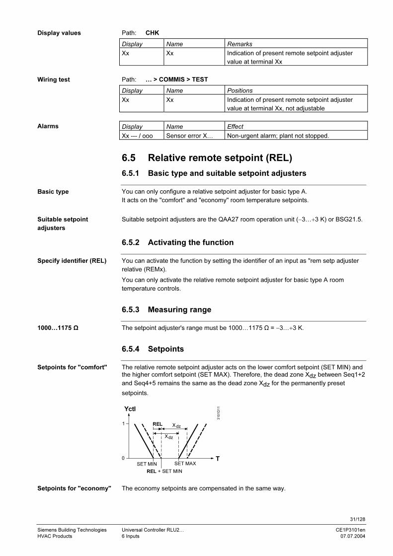
6.5.4 Setpoints
The relative remote setpoint adjuster acts on the lower comfort setpoint (SET MIN) and the higher comfort setpoint (SET MAX). Therefore, the dead zone Xdz between Seq1+2
and Seq4+5 remains the same as the dead zone Xdz for the permanently preset
setpoints.
1
0
SET MAX
3101D11
SET MIN
REL + SET MIN
REL
Yctl
T
Xdz
Xdz
The economy setpoints are compensated in the same way.
Display values
Wiring test
Alarms
Basic type
Suitable setpoint
adjusters
Specify identifier (REL)
1000…1175 Ω
Setpoints for "comfort"
Setpoints for "economy"

32/128
Siemens Building Technologies Universal Controller RLU2… CE1P3101en
HVAC Products 6 Inputs 07.07.2004
6.5.5 Error handling
When you leave the commissioning menu, the universal controller checks whether the
setpoint adjuster is connected to it.
• If the setpoint adjuster is connected at that time but is later missing during operation,
or if there is a short circuit in the cable, the controller generates a sensor alarm and
presents it on the display:
− "Xx ---" => setpoint adjuster missing
− "Xx ooo" => short circuit
• If there is no signal from the setpoint adjuster at the time, the controller operates
without the relative setpoint compensation.
If you have activated more than one input as the relative remote setpoint adjuster, the
controller only accepts the first input.
6.5.6 Settings
Path: … > COMMIS > CONF > X1…X5
Display Name Range / remark
LABEL Input identifier REL
Path: CHK
Display Name Remarks
Xx Xx Indication of present relative remote setpoint
adjuster value at terminal Xx
Path: … > COMMIS > TEST
Display Name Positions
Xx Xx Indication of present relative remote setpoint
adjuster value at terminal Xx, not adjustable
Display Name Effect
Xx --- / ooo Sensor error X… Non-urgent alarm; plant not stopped.
Connection errors
Configuration errors
Configuration
Display values
Wiring test
Alarms

33/128
Siemens Building Technologies Universal Controller RLU2… CE1P3101en
HVAC Products 6 Inputs 07.07.2004
6.6 Outside temperature (OUTS)
6.6.1 Activation and functionality
You can activate the function by setting the identifier OUTS (outside temperature) at
the respective input.
OUTS (outside temperature) is a special identifier, because it creates a large number of
internal connections.
The other properties, such as measuring range, error handling, etc. are described in
chapter 6.2 "Analog inputs".
6.6.2 Settings
Path: … > COMMIS > CONF > X1…X5
Display Name Range / remark
LABEL Input identifier OUTS
Path: … > PARA > X1
Path: … > PARA > X5
Display Name Range Factory setting
TYPE Type NI, 2XNI, T1, PT, 0-10 NI
MIN VAL Value low −50…+9999 0
MAX VAL Value high −50…+9999 100
CORR Correction −3.0…+3.0 0 K
Path: CHK
Display Name Remarks
OUTS Outside temperature
Path: … > COMMIS > TEST
Display Name Positions
OUTS Outside temperature Indication of the outside temperature (at
terminal Xx and as special OUTS point),
not adjustable
Display Name Effect
Xx --- / ooo Sensor error X… Non-urgent alarm; plant not stopped.
Activating the function
Additional functionality
Configuration
Setting values
Display values
Wiring test
Alarms
34/128
Siemens Building Technologies Universal Controller RLU2… CE1P3101en
HVAC Products 6 Inputs 07.07.2004
6.7 Room temperature (ROOM)
6.7.1 Activation and functionality
You can activate the function by setting the identifier ROOM (room temperature) at the
respective input.
ROOM (room temperature) is a special identifier, because it creates a large number of
internal connections.
The other properties, such as measuring range, error handling, etc. are described in
chapter 6.2 "Analog inputs".
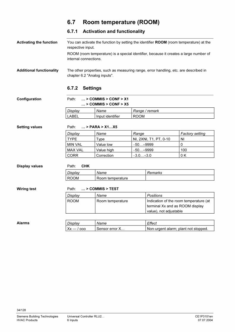
6.7.2 Settings
Path: … > COMMIS > CONF > X1
… > COMMIS > CONF > X5
Display Name Range / remark
LABEL Input identifier ROOM
Path: … > PARA > X1…X5
Display Name Range Factory setting
TYPE Type NI, 2XNI, T1, PT, 0-10 NI
MIN VAL Value low −50…+9999 0
MAX VAL Value high −50…+9999 100
CORR Correction −3.0…+3.0 0 K
Path: CHK
Display Name Remarks
ROOM Room temperature
Path: … > COMMIS > TEST
Display Name Positions
ROOM Room temperature Indication of the room temperature (at
terminal Xx and as ROOM display
value), not adjustable
Display Name Effect
Xx --- / ooo Sensor error X… Non-urgent alarm; plant not stopped.
Activating the function
Additional functionality
Configuration
Setting values
Display values
Wiring test
Alarms

35/128
Siemens Building Technologies Universal Controller RLU2… CE1P3101en
HVAC Products 7 Aggregates 07.07.2004
7 Aggregates
7.1 Pump (PUMP x)
7.1.1 Purpose and activation
The PUMP x (pump control) function block controls load-dependent pumps.
Depending on device type, the following number of pump controls (PUMP x) are
available:
Device type Number of PUMP x
RLU210 None
RLU222 Max. 2
RLU232 Max. 2
RLU236 Max. 3
In order to activate the pump control (PUMP x) you must assign a switch output (Qx).
7.1.2 Switching ON/OFF
Pumps cannot be switched on and off via the operating mode ("comfort", "economy").
The sequence controller can switch the pump on according to load. Up to 2
connections can be wired from the sequence controllers, in which case maximum
selection applies.
You can define the switch-on and switch-off points via the "ON-Y" and "OFF-Y"
settings. In normal use, we recommend switching the pump on at 5 % load, and
switching it off again at 0 % load.
In order to prevent freezing of water pipes, pumps can be operated permanently at low
outside temperatures.
In order to be able to activate this function, an outside temperature signal must be
available; see chapter 6.6, Outside temperature (OUTS). You can deactivate this
function by setting the "ON-OUTS" limit value to –50 °C.
The controller switches the circulation pump on if the outside temperature falls below
the set limit value. It switches the pump off again when the temperature has risen by 2
K above the limit value.
You can define a switch-off delay "DLY OFF" for the pumps. The switch-off delay
always acts on the switch-off command for:
• Pumps that are switched on according to load via the sequence
• Switch-on according to outside temperature
The switch-off delay does not act on the following switch-off commands:
• Plant stop due to alarm (frost [cooling sequence], main controlled variable not
available)
• Wiring test
Purpose of PUMP x
Quantity
Activation
Not possible via mode
Load-dependent by the
sequence controller
Switch-on according to
outside temperature
Switch-off delay

36/128
Siemens Building Technologies Universal Controller RLU2… CE1P3101en
HVAC Products 7 Aggregates 07.07.2004
7.1.3 Error handling
If the outside temperature signal is not available, and the value for "switch-on according
to outside temperature" is not set to –50 °C, the pump remains permanently on.
You cannot assign more than 2 sequences.
7.1.4 Function check / wiring test
During the wiring test, the pumps can be directly switched on and off via the control
switch.
The switch has the following positions:
• Off
• On
7.1.5 Priorities
The following priorities apply to pump operations:
1 ON / OFF during the wiring test
2 ON due to frost protection control (pump on heat sequence)
3 ON due to "switch-on according to outside temperature"
4 ON according to demand (see sequence controller; chapter 8.8.6 Pump Outputs)
7.1.6 Settings
Path: … > COMMIS > CONF > PUMP 1
… > COMMIS > CONF > PUMP 2
… > COMMIS > CONF > PUMP 3
Display Name Range / remark
PUMP x Output Output of Pump x (1,2,3) to a relay; adjustable
values: ---,Q1, Q2, … (free outputs only)
Path: … > PARA > PUMP 1
… > PARA > PUMP 2
… > PARA > PUMP 3
Display Name Range Factory setting
ON-Y Load-dependent ON 0…100 % 5 %
OFF-Y Load-dependent OFF 0…100 % 0 %
ON-OUTS Outside temp-dependent
ON
−50…+150 °C −50 °C
DLY OFF Switch-off delay 00.00…60.00 m.s 00.00
Path: CHK
Display Name Remarks
PUMP 1 Pump 1 Indication of present state: OFF, ON
PUMP 2 Pump 2 Indication of present state: OFF, ON
PUMP 3 Pump 3 Indication of present state: OFF, ON
Errors in operation
Note
Switch ON/OFF
Switch positions
Four priorities for pump
operation
Configuration
Setting values
Display values
37/128
Siemens Building Technologies Universal Controller RLU2… CE1P3101en
HVAC Products 7 Aggregates 07.07.2004
Path: … > COMMIS > TEST
Display Name Positions
PUMP 1 Pump 1 OFF, ON
PUMP 2 Pump 2 OFF, ON
PUMP 3 Pump 3 OFF, ON
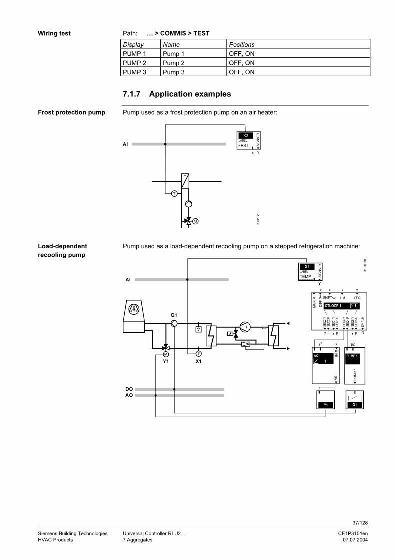
7.1.7 Application examples
Pump used as a frost protection pump on an air heater:
AI
310
1S
18
X3
x Y
SIG
NA
L Y
LABEL
FRST
Pump used as a load-dependent recooling pump on a stepped refrigeration machine:
3101S30
V
Q1
T
X1
M
Y1
Y
X1
Y
SIG
NA
L Y
LABEL
TEMP
y p y p y p
x xx
DIFF
x
Q
MAIN
LIM SEQ SHIFT
1CTLOOP 1
DV
ALM
SE
Q2 Y
SE
Q2 P
SE
Q1 Y
SE
Q1 P
SE
Q4 Y
SE
Q4 P
SE
Q5 Y
SE
Q5 P
Q1
p2
PU
MP
1PUMP 1
Y1
DO
AO
1
y2
IN X
x
A0
AO 1
AI
Wiring test
Frost protection pump
Load-dependent
recooling pump

38/128
Siemens Building Technologies Universal Controller RLU2… CE1P3101en
HVAC Products 7 Aggregates 07.07.2004
7.2 Modulating output (AO x)
7.2.1 Purpose and activation
The AO x (modulating output) function block generates a modulating DC 0…10 V
output signal for a modulating actuator with a corresponding input.
In order to activate the AO x function block, you must assign an output (Y x) to it.
7.2.2 Functions
You can connect the load signal for the modulating output from the sequence controller
to the modulating output.
Additionally, it is also possible to use an analog input (IN X) as the load signal. If one or
more (maximum 2) internal load signals and the external load signal are connected at
the same time, the controller uses maximum selection.
For example, this provides for combination of the air cooler signal from an external
dehumidification controller with that from a temperature controller.
The controller only includes the external signal if it is in the "comfort" or "economy"
mode.
You can invert any output. Meanings:
INVERS = NO: 0…100 % load = 0…100 % output
INVERS = YES: 0…100 % load = 100…0 % output
If the controller has an analog output and is switched off during operation (input D1 =
protection mode), the output signal behaves like this:
INVERS = NO: 0 % output
INVERS = YES: 100 % output
You can impose upper and lower limits on the modulating output.
In that case, 0…100 % output means "positioning signal min (MIN POS)…positioning
signal max (MAX POS)" as shown below:
0 % 100 %
0 % 0 V
100 % 10 V
MAX POS
Y
Qs
3101D05
MIN POS
Qs = load demand from the sequence controller
You can use this feature to parameterize the output for a solenoid valve with a
DC 5…7.5 V input signal, for example.
Purpose of AO x
Activation
External signal (IN X)
Note
Output inversion
(INVERS)
Limits
(MIN POS, MAX POS)
Application example

39/128
Siemens Building Technologies Universal Controller RLU2… CE1P3101en
HVAC Products 7 Aggregates 07.07.2004
7.2.3 Error handling
The controller interprets external signals at IN X with input values below 0 V as 0 %,
and signals with values over 10 V as 100 %. It performs linear interpolation on all
values in between.
Important: Pay attention to hardware limitations!
You cannot assign more than 2 sequences.
7.2.4 Wiring test (TEST)
During the wiring test, the modulating output can be directly commanded via the control
switch.
The switch has the following positions:
• ---
• 0…100 % load
Settings such as INVERS, MIN POS and MAX POS are also effective during the wiring
test.
7.2.5 Settings
Path: … > COMMIS > CONF > AO 1
… > COMMIS > CONF > AO 2
… > COMMIS > CONF > AO 3
Display Name Range / remark
AO x Modulating output Activates the modulating output; adjustable
values: ---,Y1, Y2, Y3
IN X Preselection external Adjustable values: ---, X1, X2, … (inputs with
identifier % only)
Path: … > PARA > AO 1
… > PARA > AO 2
… > PARA > AO 3
Display Name Range Factory setting
MIN POS Positioning signal min 0…100 % 0 %
MAX POS Positioning signal max 0…100 % 100 %
INVERS Inversion NO, YES NO
Path: CHK
Display Name Remarks
AO 1 Modulating output 1 0…100 %
AO 2 Modulating output 2 0…100 %
AO 3 Modulating output 3 0…100 %
Path: … > COMMIS > TEST
Display Name Positions
AO 1 Modulating output 1 ---, 0…100 %
AO 2 Modulating output 2 ---, 0…100 %
AO 3 Modulating output 3 ---, 0…100 %
Signal interpretation
Note
Switch ON/OFF
Switch positions
Note
Configuration
Setting values
Display values
Wiring test

40/128
Siemens Building Technologies Universal Controller RLU2… CE1P3101en
HVAC Products 7 Aggregates 07.07.2004
7.3 Heat recovery equipment/mixed air damper (HREC)
7.3.1 Purpose and activation
The HREC function block controls a heat recovery unit or a mixing damper with a
DC 0…10 V signal.
In order to activate the HREC function block, you must assign an output (Y x) to it.
If you use the HREC function block to control a mixing damper, ensure that the "TYPE"
is set to "DMP". This refers to the control of the outdoor air damper.
7.3.2 External preselection (IN X)
You can connect the load signal for the heat recovery unit from the sequence controller
to the heat recovery unit.
Additionally, it is also possible to use an analog input (IN X) as the load signal.
If one or more (maximum 2) internal load signals and an external load signal are
connected at the same time, the controller uses maximum selection. This provides for
combination of an external load signal from another RLU2.. universal controller with the
internal maximum economy changeover (MECH), for example.
The controller only includes the external signal if it is in the "comfort" or "economy"
mode.
7.3.3 Heat recovery unit switchover (TYPE)
In order to produce the switchover between heat recovery unit (wheel, glycol) and
mixing damper, you can invert the output signal using TYPE.
You have to make the following settings in normal operation to achieve the customary
control response:
• Energy recovery unit \_ TYPE = ERC 0…100 % load = 0…100 % output
• Mixing damper _/ TYPE = DMP 0…100 % load = 100…0 % output
If the controller has a heat recovery unit / mixing damper output and is switched off
during operation (input D1 = protection mode ), the output signal behaves like this:
• TYPE = ERC: 0 % (i.e. DC 0 V)
• TYPE = DMP: 0 % (i.e. DC 0 V)
Purpose of HREC
Activation
Notes
Maximum selection in
case of multiple load
signals
Note
Output inversion
Settings
Output signal behavior

41/128
Siemens Building Technologies Universal Controller RLU2… CE1P3101en
HVAC Products 7 Aggregates 07.07.2004
7.3.4 Limits (MIN POS, MAX POS)
You can impose upper and lower limits on the modulating output.
In that case, a 0…100 % output signal means "positioning signal min (MIN
POS)…positioning signal max (MAX POS)":
0 % 100 %
0 % 0 V
100 % 10 V
MAX POS
Y
Qs
3101D05
MIN POS
Qs = load demand from the sequence controller
You can implement a minimum damper position using positioning signal min (MIN
POS).
The controller does not include MIN POS and MAX POS in protective mode.
7.3.5 Maximum economy changeover (MECH)
The purpose of this function is to optimize the control of the heat recovery in air-
conditioning systems with regard to operating costs. It compares the available energy in
the outdoor air and exhaust air, and switches the inversion accordingly.
In order to activate the maximum economy changeover (MECH) function, assign the
corresponding inputs during configuration:
− MECH 1 (MECH input 1)
− MECH 2 (MECH input 2)
The following three changeover possibilities are available:
• Changeover via an external digital signal
• Changeover at an adjustable value
• Changeover at an adjustable difference between two measured values
Special application examples:
• Changeover via external digital signal with damper as first cooling sequence
• Changeover at adjustable difference with damper as first cooling sequence
The three possibilities and the two special application possibilities are explained on the
following pages.
Diagram
Application example
Note
Purpose
Activation
Three changeover
possibilities
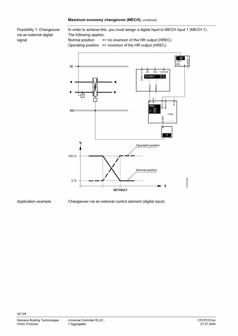
42/128
Siemens Building Technologies Universal Controller RLU2… CE1P3101en
HVAC Products 7 Aggregates 07.07.2004
Maximum economy changeover (MECH), continued
In order to achieve this, you must assign a digital input to MECH input 1 (MECH 1).
The following applies:
Normal position => no inversion of the HR output (HREC)
Operating position => inversion of the HR output (HREC)
AO
T
Y
DI
X2
Y
LABEL
SIG
NA
L Y
DIG
Y1
y2 x
....................
x
IN X
Cooler
HREC
ME
CH
1
ME
CH
2
HR
EC
y
x xx
SU
PP
LY
x
LIM SEQ CAS/CON
SE
Q1 Y
SE
Q4 Y
1CTLOOP 1
SETHEAT
100 %
0 %
T
Normal position
Operated position
310
1S
19e
n
Changeover via an external control element (digital input).
Possibility 1: Changeover
via an external digital
signal
Application example

43/128
Siemens Building Technologies Universal Controller RLU2… CE1P3101en
HVAC Products 7 Aggregates 07.07.2004
Maximum economy changeover (MECH), continued
In order to achieve this, you must assign an analog input to MECH input 1 (MECH 1).
Function:
If the set MECH limit value (MECHSET) is exceeded, the heat recovery output (HREC)
is inverted.
AO
AI
T
Y
T
Y1
y2 x
....................
x
IN X
Cooler
HREC
ME
CH
1
ME
CH
2
HR
EC
y
x xx
SU
PP
LY
x
LIM SEQ CAS/CON
SE
Q1 Y
SE
Q4 Y
1CTLOOP 1
X3
Y
SIG
NA
L Y
LABEL
OUTS
SETHEAT
100 %
0 %
OT > MECH limit value
OT < MECH limit value
310
1S
20e
n
Examples of changeover at an adjustable value:
• Changeover at an outside temperature > 25 °C
• Changeover at an outside enthalpy >30 kJ/kg
• Changeover via an external enthalpy difference calculator at an
enthalpy difference ≥2 kJ/kg
Possibility 2: Changeover
at an adjustable value
Application examples
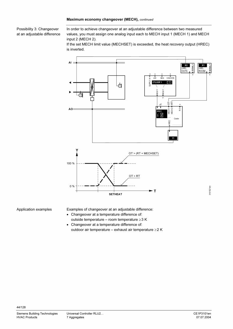
44/128
Siemens Building Technologies Universal Controller RLU2… CE1P3101en
HVAC Products 7 Aggregates 07.07.2004
Maximum economy changeover (MECH), continued
In order to achieve changeover at an adjustable difference between two measured
values, you must assign one analog input each to MECH input 1 (MECH 1) and MECH
input 2 (MECH 2).
If the set MECH limit value (MECHSET) is exceeded, the heat recovery output (HREC)
is inverted.
AO
AI
T
T
Y
T
X1
Y
SIG
NA
L Y
LABEL
ROOM
X2
Y
LABEL
SIG
NA
L Y
OUTS
Y1
y2
....................
x
IN X
Cooler
HREC
ME
CH
1
ME
CH
2
HR
EC
y
x xx
SU
PP
LY
x
LIM SEQ CAS/CON
SE
Q1 Y
SE
Q4 Y
1CTLOOP 1
SETHEAT
100 %
0 %
MECHHR
CC....................
310
1S
21e
n
OT > RT
OT > (RT + MECHSET)
OT
RT
Examples of changeover at an adjustable difference:
• Changeover at a temperature difference of:
outside temperature – room temperature ≥3 K
• Changeover at a temperature difference of:
outdoor air temperature – exhaust air temperature ≥2 K
Possibility 3: Changeover
at an adjustable difference
Application examples

45/128
Siemens Building Technologies Universal Controller RLU2… CE1P3101en
HVAC Products 7 Aggregates 07.07.2004
Maximum economy changeover (MECH), continued
In order to achieve this, you must assign a digital input to MECH input 1 (MECH 1).
The following applies:
Normal position => inversion of mixed air damper output (HREC)
Operating position => no inversion of mixed air damper output (HREC)
AO
T
Y
DI
X2
Y
LABEL
SIG
NA
L Y
DIG
Y1
y2 x
....................
x
IN X
Cooler
HREC
ME
CH
1
ME
CH
2
HR
EC
y
x xx
SU
PP
LY
x
LIM SEQ CAS/CON
SE
Q1 Y
SE
Q4 Y
1CTLOOP 1 Y2
Y6Y1
M
M
M
SETCOOL
100 %
0 %
T
Normal position
Operated position
310
1S
40e
n
Special application
example 1:
Changeover via external
digital signal with damper
as first cooling sequence
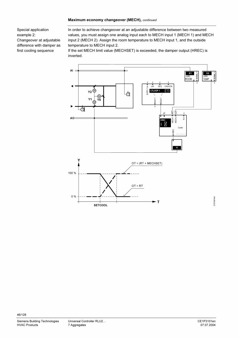
46/128
Siemens Building Technologies Universal Controller RLU2… CE1P3101en
HVAC Products 7 Aggregates 07.07.2004
Maximum economy changeover (MECH), continued
In order to achieve changeover at an adjustable difference between two measured
values, you must assign one analog input each to MECH input 1 (MECH 1) and MECH
input 2 (MECH 2). Assign the room temperature to MECH input 1, and the outside
temperature to MECH input 2.
If the set MECH limit value (MECHSET) is exceeded, the damper output (HREC) is
inverted.
AO
AI
T
T
Y
T
X2
Y
SIG
NA
L Y
LABEL
TEMP
X1
Y
LABEL
SIG
NA
L Y
ROOM
Y1
y2
....................
x
IN X
Cooler
HREC
ME
CH
1
ME
CH
2
HR
EC
y
x xx
SU
PP
LY
x
LIM SEQ CAS/CON
SE
Q1 Y
SE
Q4 Y
1CTLOOP 1
SETCOOL
Y2
Y6Y1
M
M
M
100 %
0 %
310
1S
41e
n
OT < (RT + MECHSET)
OT > RT
OT
RT
Special application
example 2:
Changeover at adjustable
difference with damper as
first cooling sequence
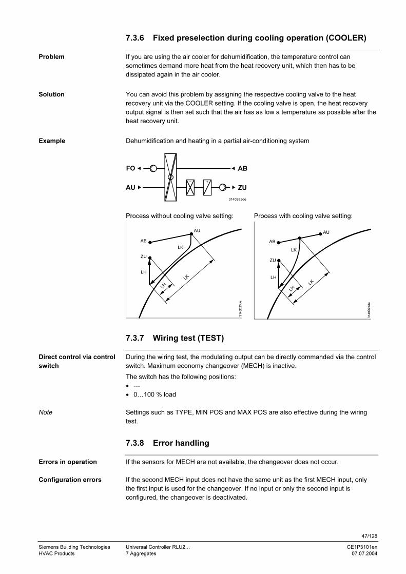
47/128
Siemens Building Technologies Universal Controller RLU2… CE1P3101en
HVAC Products 7 Aggregates 07.07.2004
7.3.6 Fixed preselection during cooling operation (COOLER)
If you are using the air cooler for dehumidification, the temperature control can
sometimes demand more heat from the heat recovery unit, which then has to be
dissipated again in the air cooler.
You can avoid this problem by assigning the respective cooling valve to the heat
recovery unit via the COOLER setting. If the cooling valve is open, the heat recovery
output signal is then set such that the air has as low a temperature as possible after the
heat recovery unit.
Dehumidification and heating in a partial air-conditioning system
3140S29de
FO
ZU
AB
AU
Process without cooling valve setting: Process with cooling valve setting:
LK
3140D23de
LH
LH
ZU
AB
LK
AU
LK
3140D24de
LH
LH
ZU
AB
LK
AU
7.3.7 Wiring test (TEST)
During the wiring test, the modulating output can be directly commanded via the control
switch. Maximum economy changeover (MECH) is inactive.
The switch has the following positions:
• ---
• 0…100 % load
Settings such as TYPE, MIN POS and MAX POS are also effective during the wiring
test.
7.3.8 Error handling
If the sensors for MECH are not available, the changeover does not occur.
If the second MECH input does not have the same unit as the first MECH input, only
the first input is used for the changeover. If no input or only the second input is
configured, the changeover is deactivated.
Problem
Solution
Example
Direct control via control
switch
Note
Errors in operation
Configuration errors

48/128
Siemens Building Technologies Universal Controller RLU2… CE1P3101en
HVAC Products 7 Aggregates 07.07.2004
7.3.9 Settings
Path: … > COMMIS > CONF > HREC
Display Name Range / remark
HREC Mixing damper/HR Activates heat recovery; adjustable values: ---,
Y1, Y2, …
MECH 1 MECH input 1 Adjustable values: ---, X1, X2, … (only °C, 0.0,
0000, digital)
MECH 2 MECH input 2 Adjustable values: ---, X1, X2, … (only °C, 0.0,
0000)
COOLER Air cooling coil valve ---, AO1, AO2, AO3, STP1, STP2, STP3, SLIN,
SBIN, 3P
IN X Preselection external Adjustable values: ---, X1, X2, … (inputs with
identifier % only)
Path: … > PARA > HREC
Display Name Range Factory setting
MIN POS Positioning signal min 0…100 % 0 %
MAX POS Positioning signal max 0…100 % 100 %
MECHSET MECH limit value 3 K, 20 °C
TYPE Type ERC, DMP ERC
Path: CHK
Display Name Remarks
HREC Mixing damper/HR 0…100 %
Path: … > COMMIS > TEST
Display Name Positions
HREC Mixing damper/HR ---, 0…00 %
Configuration
Setting values
Display values
Wiring test

49/128
Siemens Building Technologies Universal Controller RLU2… CE1P3101en
HVAC Products 7 Aggregates 07.07.2004
7.4 Variable step switch (STEP Vx)
7.4.1 Purpose and activation
The STEP Vx (variable step switch) function block switches multi-step aggregates. All
outputs can be set individually.
Depending on device type, the following number of variable step switches are available:
Device type Number of variable step switches
RLU210 None
RLU222 1 = with a maximum of 2 steps
RLU232 1 = with a maximum of 2 steps
RLU236 1 = with a maximum of 6 steps
1 = with a maximum of 2 steps (6 relays available in total)
In order to activate the variable step switch, assign a relay Q… to the STEP 1 output.
Additionally, you can also configure the available analog output AO with each step
switch. The same settings are possible as with the modulating output, i.e. the AO
function block. Therefore, you can also assign an output Y.
7.4.2 Operating principle
With variable step switching, you can set the digital outputs individually according to the
load.
You can define the digital output's direction of action via the switching point settings.
The digital outputs can overlap each other.
The following diagram shows an example of load connection.
0 %
3101D1720 % 40 % 60 % 20%80 %
S1-ON > S1-OFF
S2-ON < S2-OFF
MAX POS
MIN POS
Q
Y+Q
S2-ON
S2-OFF
S1-ON
S1-OFF
AO
XP
100 %
STEP 1
STEP 2
If the step switch is controlled by two internal sequence controllers, the larger signal is
effective (maximum selection).
Additionally, you can enter a common locking time for the digital outputs. This ensures
that a step which has just switched off remains off for the set period of time.
You cannot enter a run-on time for the step switches, since there are no open-loop
control functions in the Synco 200 product range.
Purpose of STEP Vx
Quantity
Activation
Note
Load connection
Example
Locking time (OFFTIME)
No run-on time in the step
switch
50/128
Siemens Building Technologies Universal Controller RLU2… CE1P3101en
HVAC Products 7 Aggregates 07.07.2004
Operating principle, continued
If the variable step switch is controlling an electric air heater, you must solve the fan
run-on using external means.
7.4.3 Preselection external (IN X)
You can configure an analog input as a preselection for the step switch. The controller
performs a maximum selection with the internal signals.
For example, you can use this feature to implement the following function:
External control. The RLU236 provides the step switch function only.
The controller only includes the external signal if it is in the "comfort" or "economy"
mode.
7.4.4 Output inversion (INVERS)
You can invert the analog output. Meanings:
INVERS = NO: 0…100 % load = 0…100 % output
INVERS = YES: 0…100 % load = 100…0 % output
If the controller has a variable step switch and is switched off during operation (input D1
= protection mode), the output signal behaves like this:
INVERS = NO: 0 % output
INVERS = YES: 100 % output
7.4.5 Function check / wiring test
During the wiring test, the step switch can be controlled directly via the control switch.
The switch has the following positions:
• ---
• 0…100 % load
Settings such as INVERS, MIN POS and MAX POS are also effective during the wiring
test.
7.4.6 Priorities
The following two priorities apply to the step switch:
1 ON / OFF during the wiring test
2 Demand-controlled by the sequence controller (preselection in normal operation)
and the IN X external signal (maximum selection)
Note
Maximum selection in
case of multiple
preselections
Note
Definition and behavior
Switch ON/OFF
Switch positions
Note
Two priorities

51/128
Siemens Building Technologies Universal Controller RLU2… CE1P3101en
HVAC Products 7 Aggregates 07.07.2004
7.4.7 Settings
Path: … > COMMIS > CONF > STEP V1
… > COMMIS > CONF > STEP V2
Display Name Range / remark
STEP 1 Step 1 Activates the step switch, and selects the
number of steps; adjustable values: ---, Q1,
Q2, … (free outputs only)
STEP 2 Step 2 ---, Q1, Q2, … (free outputs only)
STEP 3 Step 3 ---, Q1, Q2, … (free outputs only)
STEP 4 Step 4 ---, Q1, Q2, … (free outputs only)
STEP 5 Step 5 ---, Q1, Q2, … (free outputs only)
STEP 6 Step 6 ---, Q1, Q2, … (free outputs only)
AO Modulating output ---, Y1, Y2, … (free outputs only)
IN X Preselection external ---, X1, X2, … (inputs with identifier % only)
Path: … > PARA > STEP V1
… > PARA > STEP V2
Display Name Range Factory setting
S1-ON [Step 1] ON 0…100 % 17 %
S1-OFF [Step 1] OFF 0…100 % 0 %
S2-ON [Step 2] ON 0…100 % 33 %
S2-OFF [Step 2] OFF 0…100 % 17 %
S3-ON [Step 3] ON 0…100 % 50 %
S3-OFF [Step 3] OFF 0…100 % 33 %
S4-ON [Step 4] ON 0…100 % 67 %
S4-OFF [Step 4] OFF 0…100 % 50 %
S5-ON [Step 5] ON 0…100 % 83 %
S5-OFF [Step 5] OFF 0…100 % 67 %
S6-ON [Step 6] ON 0…100 % 100 %
S6-OFF [Step 6] OFF 0…100 % 83 %
OFFTIME Locking time 00.00…10.00 m.s 00.00 m.s
MIN POS Positioning signal min 0…100 % 0 %
MAX POS Positioning signal max 0…100 % 100 %
INVERS Inversion NO, YES NO
STEP V1 has a maximum of 2 steps.
Therefore, the setting values for S3-ON to S6-OFF are not shown.
Path: CHK
Display Name Remarks
STEP V1 Variable step switch 1 0…100 %
STEP V2 Variable step switch 2 0…100 %
Path: … > COMMIS > TEST
Display Name Positions
STEP V1 Variable step switch 1 ---, 0…100 %
STEP V2 Variable step switch 2 ---, 0…100 %
Configuration
Setting values
Note
Display values
Wiring test
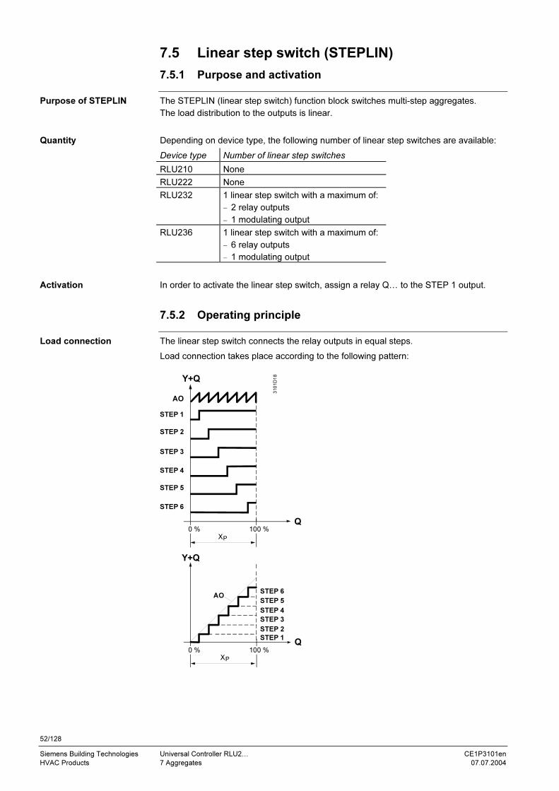
52/128
Siemens Building Technologies Universal Controller RLU2… CE1P3101en
HVAC Products 7 Aggregates 07.07.2004
7.5 Linear step switch (STEPLIN)
7.5.1 Purpose and activation
The STEPLIN (linear step switch) function block switches multi-step aggregates.
The load distribution to the outputs is linear.
Depending on device type, the following number of linear step switches are available:
Device type Number of linear step switches
RLU210 None
RLU222 None
RLU232 1 linear step switch with a maximum of:
− 2 relay outputs
− 1 modulating output
RLU236 1 linear step switch with a maximum of:
− 6 relay outputs
− 1 modulating output
In order to activate the linear step switch, assign a relay Q… to the STEP 1 output.
7.5.2 Operating principle
The linear step switch connects the relay outputs in equal steps.
Load connection takes place according to the following pattern:
3101D18
Q0 %
Y+Q
AO
Q0 %
Y+Q
XP
XP
100 %
100 %
STEP 1
STEP 2
STEP 3
STEP 4
STEP 5
STEP 6
STEP 1
AO
STEP 2
STEP 3
STEP 4
STEP 5
STEP 6
Purpose of STEPLIN
Quantity
Activation
Load connection

53/128
Siemens Building Technologies Universal Controller RLU2… CE1P3101en
HVAC Products 7 Aggregates 07.07.2004
Example with 2 digital outputs:
0 %
a a a a a a
0 %
AO
¼ a
3101D19
Q
0Y + 2Q
S2-ON
S1-ON
S2-OFF
S1-OFF
1Y + 2Q
Q
MAX POS
MIN POS
XP XP
100 % 100 %
STEP 1
STEP 2
1) steps of (number
load % 100 a Interval
+
=
Additionally, you can enter a common locking time for the relay outputs. This ensures
that a step that has just switched off remains off for the set period of time.
In order to prevent excessively quick startup, you can enter a common startup delay
time. This delay makes the controller wait for the set time between the steps during
startup.
With the linear step switch, you can set a priority changeover of the outputs.
The priorities change at fixed intervals of roughly one week (always after 7 x 24 = 168
hours).
The changeover takes place like this (example with 4 steps):
Week 1: 1, 2, 3, 4
Week 2: 2, 3, 4, 1
Week 3: 3, 4, 1, 2
Week 4: 4, 1, 2, 3
Week 5: 1, 2, 3, 4
etc.
The priority changeover is reset in case of a power outage.
7.5.3 External preselection (IN X)
You can configure an analog input (IN X) as a preselection for the step switch. The
controller performs a maximum selection with the internal signals.
For example, you can use this feature to implement the following function:
DX cooling coil control, maximum selection between internal temperature control and
dehumidification signal from an external dehumidification controller.
The controller only includes the external signal if it is in the "comfort" or "economy"
mode.
Switching interval
Locking time (OFFTIME)
Startup delay (ON DLY)
Run priority changeover
(PRIO CH)
Notes
Maximum selection
Example
Note
54/128
Siemens Building Technologies Universal Controller RLU2… CE1P3101en
HVAC Products 7 Aggregates 07.07.2004
7.5.4 Output inversion (INVERS)
You can invert the step switch's analog output. Meanings:
INVERS = NO: 0…100 % load = 0…100 % output
INVERS = YES: 0…100 % load = 100…0 % output
The same settings are possible for this analog output as for the modulating output, i.e.
the AO function block.
If the controller has a linear step switch and is switched off during operation (input D1 =
protection mode), the output signal behaves like this:
INVERS = NO: 0 % output
INVERS = YES: 100 % output
7.5.5 Function check / wiring test
During the wiring test, the step switch can be controlled directly via the control switch.
The switch has the following positions:
• ---
• 0…100 %
Settings such as INVERS, MIN POS and MAX POS are also effective during the wiring
test.
7.5.6 Priorities
The following two priorities apply to the step switch:
1 ON / OFF during the wiring test
2 Demand-controlled by the sequence controller (preselection in normal operation)
and the external preselection (maximum selection)
7.5.7 Settings
Path: … > COMMIS > CONF > STEPLIN
Display Name Range / remark
STEP 1 Step 1 Activates the step switch, and selects the
number of steps; adjustable values: ---, Q1, Q2,
… (free outputs only)
STEP 2 Step 2 ---, Q1, Q2, … (free outputs only)
STEP 3 Step 3 ---, Q1, Q2, … (free outputs only)
STEP 4 Step 4 ---, Q1, Q2, … (free outputs only)
STEP 5 Step 5 ---, Q1, Q2, … (free outputs only)
STEP 6 Step 66 ---, Q1, Q2, … (free outputs only)
AO Modulating output ---, N.Y1, N.Y2, … (free outputs only)
IN X Preselection external ---, X1, X2, … (inputs with identifier % only)
Definition and behavior
Switch ON/OFF
Switch positions
Note
Configuration

55/128
Siemens Building Technologies Universal Controller RLU2… CE1P3101en
HVAC Products 7 Aggregates 07.07.2004
Path: … > PARA > STEPLIN
Display Name Range Factory setting
ON DLY Startup delay 00.00…00.10 mm.ss 00.00
PRIO CH Run priority changeover NO, YES NO
OFFTIME Locking time 00.00…00.10 mm.ss 00.00
MIN POS Positioning signal min 0…100 % 0 %
MAX POS Positioning signal max 0…100 % 100 %
INVERS Inversion NO, YES NO
Path: CHK
Display Name Remarks
STEPLIN Linear step switch 0…100 %
Path: … > COMMIS > TEST
Display Name Positions
STEPLIN Linear step switch ---, 0…100 %
Setting values
Display values
Wiring test

56/128
Siemens Building Technologies Universal Controller RLU2… CE1P3101en
HVAC Products 7 Aggregates 07.07.2004
7.6 Binary step switch (STEPBIN)
7.6.1 Purpose and activation
The STEPBIN (binary step switch) function block switches multi-step aggregates. The
aggregates must be sized according to the binary load distribution.
Depending on device type, the following number of binary step switches are available:
Device type Number of binary step switches
RLU210 None
RLU222 None
RLU232 1 binary step switch with a maximum of:
− 2 relay outputs(= 3 load steps)
− 1 modulating output
RLU236 1 binary step switch with a maximum of:
− 4 relay outputs(= 15 load steps)
− 1 modulating output
In order to activate the binary step switch, assign a relay Q… to the STEP 1 output.
7.6.2 Operating principle
The binary step switch distributes the digital outputs with the number of load steps
according to the following table over the total contact rating of the aggregate.
a) If configured without the analog output:
Load distribution Configured
outputs Relay 1 Relay 2 Relay 3 Relay 4
Number of
load steps
0Y+2Q Q1 = 1/3 Q2 = 2/3 3
0Y+3Q Q1 = 1/7 Q2 = 2/7 Q3 = 4/7 7
0Y+4Q Q1 = 1/15 Q2 = 2/15 Q3 = 4/15 Q4 = 8/15 15
b) If configured with an analog output:
Load distribution Configured
outputs Y Relay 1 Relay 2 Relay 3 Relay 4
Number of
load steps
1Y+2Q Y = 1/4 Q1 = 1/4 Q2 = 2/4 4
1Y+3Q Y = 1/8 Q1 = 1/8 Q3 = 2/8 Q3 = 4/8 8
1Y+4Q Y = 1/16 Q1 = 1/16 Q2 = 2/16 Q3 = 4/16 Q4 = 8/16 16
0Y = no analog output
1Y = 1 analog output
Purpose of STEPBIN
Quantity
Activation
Load distribution
(demand calculation)
Explanation
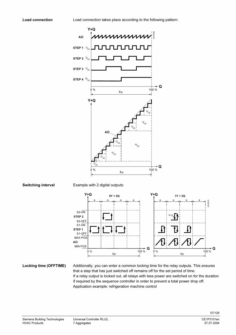
57/128
Siemens Building Technologies Universal Controller RLU2… CE1P3101en
HVAC Products 7 Aggregates 07.07.2004
Load connection takes place according to the following pattern:
3101D20
Q
1/16
1/16
2/16
4/16
2/16
2/16
4/16
2/16
8/16
Q100 %0 %
2/16
4/16
8/16
Y+Q
Y+Q
0 % 100 %
XP
AO
STEP 1
AO
STEP 2
STEP 3
STEP 4
XP
Example with 2 digital outputs:
3101D21
0 %
a a a a
0Y + 2Q
0 %
a a a a
1Y + 2QY+Q
Q
S2-ON
S2-OFF
S1-ON
S1-OFF
MAX POS
MIN POSQ
¼ a
Y+Q
XP XP
100 %100 %
AO
STEP 1
STEP 2
Additionally, you can enter a common locking time for the relay outputs. This ensures
that a step that has just switched off remains off for the set period of time.
If a relay output is locked out, all relays with less power are switched on for the duration
if required by the sequence controller in order to prevent a total power drop off.
Application example: refrigeration machine control
Load connection
Switching interval
Locking time (OFFTIME)
58/128
Siemens Building Technologies Universal Controller RLU2… CE1P3101en
HVAC Products 7 Aggregates 07.07.2004
7.6.3 External preselection (IN X)
You can configure an analog input (IN X) as a preselection for the step switch. The
controller performs a maximum selection with the internal signals.
For example, you can use this feature to implement the following function:
External control – the RLU236 provides the step switch function only.
The controller only includes the external signal if it is in the "comfort" or "economy"
mode.
7.6.4 Output inversion (INVERS)
You can invert the step switch's analog output. Meanings:
INVERS = NO: 0…100 % load = 0…100 % output
INVERS = YES: 0…100 % load = 100…0 % output
The same settings are possible for this analog output as for the modulating output, the
AO function block.
If the controller has a binary step switch and is switched off during operation (input D1 =
protection mode), the output signal behaves like this:
INVERS = NO: 0 % output
INVERS = YES: 100 % output
7.6.5 Function check / wiring test
During the wiring test, the step switch can be controlled directly via the control switch.
The switch has the following positions:
• ---
• 0…100 %
Settings such as INVERS, MIN POS and MAX POS are also effective during the wiring
test.
The following priorities apply to the step switch:
1 ON / OFF during the wiring test
2 According to the actuating signal from the sequence controller (preselection in
normal operation) or an external signal (maximum selection)
Maximum selection in
case of multiple
preselections
Note
Definition and behavior
Switch ON/OFF
Switch positions
Note
Priorities

59/128
Siemens Building Technologies Universal Controller RLU2… CE1P3101en
HVAC Products 7 Aggregates 07.07.2004
7.6.6 Settings
Path: … > COMMIS > CONF > STEPBIN
Display Name Range / remark
STEP 1 Step 1 Activates the step switch, and selects the
number of steps; adjustable values: ---, Q1, Q2,
… (free outputs only)
STEP 2 Step 2 ---, Q1, Q2, … (free outputs only)
STEP 3 Step 3 ---, Q1, Q2, … (free outputs only)
STEP 4 Step 4 ---, Q1, Q2, … (free outputs only)
AO Modulating output ---, Y1, Y2, … (free outputs only)
IN X Preselection external ---, X1, X2, … (inputs with identifier % only)
Path: … > PARA > STEPBIN
Display Name Range Factory setting
OFFTIME Locking time 00.00…00.10 mm.ss 00.00
MIN POS Positioning signal min 0…100 % 0 %
MAX POS Positioning signal max 0…100 % 100 %
INVERS Inversion NO, YES NO
Path: CHK
Display Name Remarks
STEPBIN Binary step switch 0…100%
Path: … > COMMIS > TEST
Display Name Positions
STEPBIN Binary step switch ---, 0…100 %
Configuration
Setting values
Display values
Wiring test
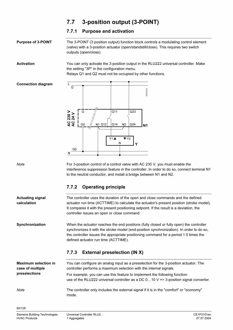
60/128
Siemens Building Technologies Universal Controller RLU2… CE1P3101en
HVAC Products 7 Aggregates 07.07.2004
7.7 3-position output (3-POINT)
7.7.1 Purpose and activation
The 3-POINT (3 position output) function block controls a modulating control element
(valve) with a 3-position actuator (open/standstill/close). This requires two switch
outputs (open/close).
You can only activate the 3-position output in the RLU222 universal controller. Make
the setting "3P" in the configuration menu.
Relays Q1 and Q2 must not be occupied by other functions.
L
G
G
G0
G0
N
3101A14
AC
230 V
AC
24 V
Q24
Q23
Q12 Q14
Q11
N1 N2 N1
Y1 Y2
NY
For 3-position control of a control valve with AC 230 V, you must enable the
interference suppression feature in the controller. In order to do so, connect terminal N1
to the neutral conductor, and install a bridge between N1 and N2.
7.7.2 Operating principle
The controller uses the duration of the open and close commands and the defined
actuator run time (ACTTIME) to calculate the actuator's present position (stroke model).
It compares it with the present positioning setpoint. If the result is a deviation, the
controller issues an open or close command.
When the actuator reaches the end positions (fully closed or fully open) the controller
synchronizes it with the stroke model (end-position synchronization). In order to do so,
the controller issues the appropriate positioning command for a period 1.5 times the
defined actuator run time (ACTTIME).
7.7.3 External preselection (IN X)
You can configure an analog input as a preselection for the 3-position actuator. The
controller performs a maximum selection with the internal signals.
For example, you can use this feature to implement the following function:
use of the RLU222 universal controller as a DC 0…10 V => 3-position signal converter.
The controller only includes the external signal if it is in the "comfort" or "economy"
mode.
Purpose of 3-POINT
Activation
Connection diagram
Note
Actuating signal
calculation
Synchronization
Maximum selection in
case of multiple
preselections
Note
61/128
Siemens Building Technologies Universal Controller RLU2… CE1P3101en
HVAC Products 7 Aggregates 07.07.2004
7.7.4 Function check / wiring test (TEST)
During the wiring test, the 3-position output can be directly commanded via the control
switch.
The switch has the following positions:
• Standstill (----)
• Open (OPEN)
• Close (CLOS)
When you enter the commissioning menu (COMMIS) the 3-position actuator travels to
the 0 % position (CLOS).
When you leave the COMMIS menu, the controller does not compensate for any
changes made to the 3-position output during the wiring test. This does not take place
until after the first synchronization.
7.7.5 Priorities
The following two priorities apply to the 3-position output:
1 ON / OFF during the wiring test
2 According to the actuating signal from the sequence controller (preselection in
normal operation) and external preselection (maximum selection)
7.7.6 Settings
Path: … > COMMIS > CONF > 3-POINT
Display Name Range / remark
3P 3-position Activates the 3-position output open function;
adjustable values: NO, YES
IN X Preselection external ---, X1, X2, … (inputs with identifier % only)
Path: … > PARA > 3-POINT
Display Name Range Factory setting
ACTTIME Actuator run time 10…180 s 120 s
Path: CHK
Display Name Remarks
3P 3-position 0…100 %
Path: … > COMMIS > TEST
Display Name Positions
3P 3-position ---, OPEN, CLOS
Switch ON/OFF
Switch positions
Notes
Two priorities
Configuration
Setting values
Display values
Wiring test
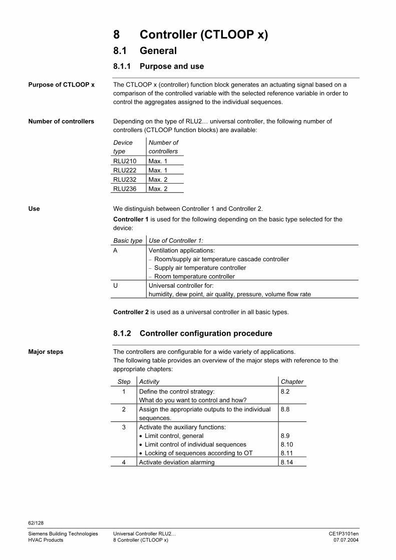
62/128
Siemens Building Technologies Universal Controller RLU2… CE1P3101en
HVAC Products 8 Controller (CTLOOP x) 07.07.2004
8 Controller (CTLOOP x)
8.1 General
8.1.1 Purpose and use
The CTLOOP x (controller) function block generates an actuating signal based on a
comparison of the controlled variable with the selected reference variable in order to
control the aggregates assigned to the individual sequences.
Depending on the type of RLU2… universal controller, the following number of
controllers (CTLOOP function blocks) are available:
Device
type
Number of
controllers
RLU210 Max. 1
RLU222 Max. 1
RLU232 Max. 2
RLU236 Max. 2
We distinguish between Controller 1 and Controller 2.
Controller 1 is used for the following depending on the basic type selected for the
device:
Basic type Use of Controller 1:
A Ventilation applications:
− Room/supply air temperature cascade controller
− Supply air temperature controller
− Room temperature controller
U Universal controller for:
humidity, dew point, air quality, pressure, volume flow rate
Controller 2 is used as a universal controller in all basic types.
8.1.2 Controller configuration procedure
The controllers are configurable for a wide variety of applications.
The following table provides an overview of the major steps with reference to the
appropriate chapters:
Step Activity Chapter
1 Define the control strategy:
What do you want to control and how?
8.2
2 Assign the appropriate outputs to the individual
sequences.
8.8
3 Activate the auxiliary functions:
• Limit control, general
• Limit control of individual sequences
• Locking of sequences according to OT
8.9
8.10
8.11
4 Activate deviation alarming 8.14
Purpose of CTLOOP x
Number of controllers
Use
Major steps
63/128
Siemens Building Technologies Universal Controller RLU2… CE1P3101en
HVAC Products 8 Controller (CTLOOP x) 07.07.2004
8.1.3 Limits and setpoint influences
The following functions can have an influence on setpoints:
• Summer/winter compensation
• Universal setpoint compensation
• Absolute remote setpoint
• Relative remote setpoint
The setpoint influences differ depending on the selected control strategy. They are
described under the various control strategies.
8.1.4 Function priorities
If multiple functions that act on the same controller are active at the same time, the
following priorities apply:
1 Frost protection FROST
2 Locking of sequences according to outside temperature
3 Limiting of individual sequence SEQ
4 General limit controller (LIM)
5 Sequence controller
8.2 Control strategies and setpoints
8.2.1 Setting up the control strategy
Controller 1 in basic type A is intended for temperature control. You can choose
between a variety of control strategies. In order to do so, you must make the following
settings:
Control strategy Setting value Setting
Room temperature control
See chapter 8.3
(Room temperature must be available)
SUPPLY
Xx
CAS/CON
---
ROOM
Not relevant
Room/supply air temperature cascade
control
See chapter 8.4
(Room temperature must be available)
SUPPLY
Xx
CAS/CON
Xx
ROOM
Xx possible changeover
Supply air temperature control
See chapter 8.5
(If the room temperature is not available,
the controller automatically operates with
constant supply air temperature)
SUPPLY
Xx
CAS/CON
Xx
No ROOM defined
Not relevant
If you do not select a supply air temperature sensor (SUPPLY), the main controlled
variable of Controller 1 automatically becomes the room temperature (ROOM).
CAS/CON provides for changeover from cascade control in summer to supply air
control in winter (if the heating is ON).
The control strategy for Controller 1, basic type U, is the same as the control strategies
for Controller 2 (all basic types).
In order to activate the controller, assign the main controlled variable (MAIN).
Controller 2 is usable universally. The choice of main controlled variable determines the
physical unit.
You can also use Controller 2 for differential control.
Influence of functions
Five priorities
Control strategies
for Controller 1,
basic type A
Notes
Control strategies
for Controller 1,
basic type U
Control strategies
for Controller 2
64/128
Siemens Building Technologies Universal Controller RLU2… CE1P3101en
HVAC Products 8 Controller (CTLOOP x) 07.07.2004
8.2.2 Configuration
Path: … > COMMIS > CONF > X1…X5
Display Name Adjustable values / remark
LABEL Input identifier Activates the room temperature sensor.
Adjustable value:
ROOM
Path: … > COMMIS > CONF > CTLOOP 1
Display Name Adjustable values / remark
SUPPLY Supply air
temperature
Activates the supply air temperature sensor.
Adjustable values:
---, X1, X2, … (analog values only)
CAS/CON Casc/const
changeover input
Activates the control strategy.
Adjustable values:
---, X1, X2, … (digital values only).
Input signal meanings:
0 = room/supply air cascade control
1 = supply air temperature control (constant)
Path: … > COMMIS > CONF > CTLOOP 1
Path: … > COMMIS > CONF > CTLOOP 2
Display Name Adjustable values / remark
MAIN Main controlled
variable
Activates the main controlled variable.
Adjustable values:
---, X1, X2, … (analog values only)
DIFF Differential input Activates difference control
Adjustable values:
---, X1, X2, … (analog values only)
8.2.3 Application examples
Typical application examples for various control strategies:
• Room or exhaust air temperature control
• Supply air temperature control
• Room or exhaust air temperature control with supply air limit control
• Room or exhaust air temperature control with supply air cascade control
• Simple heating system with outside temperature compensated supply temperature
(without room influence), thermostatic valves
• Differential pressure control
• Cascade control (summer) / supply air temperature control (winter) changeover
Controller 1,
basic type A
Controller 1,
basic type U
Controller 2,
all plant types
Selection

65/128
Siemens Building Technologies Universal Controller RLU2… CE1P3101en
HVAC Products 8 Controller (CTLOOP x) 07.07.2004
8.3 Room temperature control
8.3.1 Activation and setpoints
Room temperature control is always activated for Controller 1, basic type A. This
control process is already active in the device as delivered – you do not have to
activate it.
You can assign individual setpoints for the "comfort" and "economy" modes. We
distinguish the following setpoints in the two modes:
− SETHEAT lower setpoint "heating" (sequence 1+2)
− SETCOOL upper setpoint "cooling" (sequence 4+5)
SETHEAT SETCOOL
3140D33en
Heating CoolingMan
ipula
ted v
ari
able
Load
Seq 3 Seq 2 Seq 1 Seq 5Seq 4
The following functions can have an influence on setpoints:
• Locking of a sequence according to outside temperature
• Absolute remote setpoint
• Relative remote setpoint
• Summer/winter compensation
8.3.2 Error handling
When you leave the commissioning menu, the universal controller checks whether a
room temperature sensor is connected to it.
• If a room temperature value is available at that time but is later missing, the
controller generates a sensor alarm, and presents it on the display:
"Xx ---" => sensor missing or "Xx ooo" => short circuit
• If there is no room temperature value at the time (main controlled variable in this
case), the controller switches the plant off (MAINALM):
8.3.3 Settings
Path: SET
Display Name Range Factory setting
SETCOOL
Economy
cooling setpoint
Comfort cooling setpoint to 50 °C 28 °C
SETCOOL
Comfort cooling
setpoint
Comfort heating setpoint to
economy cooling setpoint
24 °C
SETHEAT
Comfort heating
setpoint
Economy heating setpoint to
comfort cooling setpoint
21 °C
SETHEAT
Economy
heating setpoint
0 °C to comfort heating setpoint 19 °C
The heating setpoints are limited by the cooling setpoints. Apply the following
procedure to eliminate this limitation:
1. Configure the cooling sequence, i.e. connect with an analog output (AO1, AO2).
2. Raise the cooling setpoints as far as necessary.
3. Set the heating setpoints to the value you want.
4. Remove the configured cooling sequence again.
Activation
Setpoints
Influences on the setpoints
Room temperature
sensor present?
Setting values
Setting heating
setpoints above
24 °C – how-to

66/128
Siemens Building Technologies Universal Controller RLU2… CE1P3101en
HVAC Products 8 Controller (CTLOOP x) 07.07.2004
8.4 Room/supply air temperature cascade controller
8.4.1 Activating the cascade controller
You can only activate the cascade controller for Controller 1, basic type A. In order to
activate the room/supply air temperature cascade controller, assign an input to the
supply air temperature (SUPPLY).
If you additionally define a terminal as the CAS/CON input, the input must be "0".
You can use this terminal to switch the control strategy between cascade control and
supply air control:
• Cascade control CAS/CON = 0
• Supply air temperature control CAS/CON = 1; behavior, see chapter 8.2.1
8.4.2 Operating principle
This diagram shows the principle of room/supply air temperature cascade control:
T
T
TSu
TR
w
SpTSuC
SpTSuH
3101S38
CTLOOP 1
PIPID
The main controlled variable is the room temperature TR; the auxiliary controlled
variable is the supply air temperature TSu. The room temperature controller has PI
control action; the supply air temperature controller has PID control action. The result is
a PI+PID room/supply air temperature cascade control process.
The room temperature controller sets the present setpoints SpTSuC and SpTSuH for
the supply air temperature controller within the selected limit values.
The following diagram shows the setpoint settings for cascade control, and the principle
by which the CTLOOP 1 controller block generates the supply air temperature setpoints
SpTSuC and SpTSuH:
SU MIN
T
T
SU MAXSU DMIN
SU DMAX
SpTSu
t
SpTSuC
SpTSuH
TSu
TR
SpSu
TR
SETCOOL
SETCOOL SETHEAT
SETHEAT
CTLOOP 1
LIM
3101S39
Cascade controller only
with Controller 1, basic
type A
Function of the
CAS/CON input
Principle
Setpoint derivation
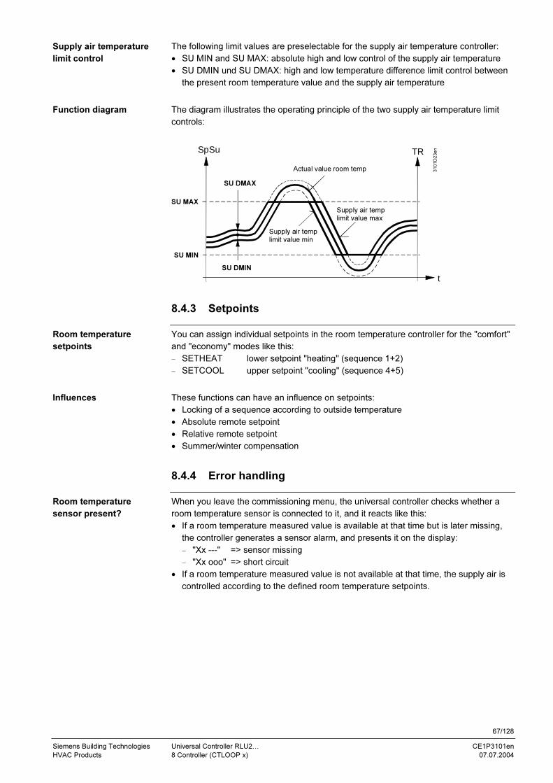
67/128
Siemens Building Technologies Universal Controller RLU2… CE1P3101en
HVAC Products 8 Controller (CTLOOP x) 07.07.2004
The following limit values are preselectable for the supply air temperature controller:
• SU MIN and SU MAX: absolute high and low control of the supply air temperature
• SU DMIN und SU DMAX: high and low temperature difference limit control between
the present room temperature value and the supply air temperature
The diagram illustrates the operating principle of the two supply air temperature limit
controls:
SpSu
t
SU MAX
SU MIN
SU DMAX
SU DMIN
TR
Supply air temp limit value max
Supply air temp limit value min
Actual value room temp 3101D23en
8.4.3 Setpoints
You can assign individual setpoints in the room temperature controller for the "comfort"
and "economy" modes like this:
− SETHEAT lower setpoint "heating" (sequence 1+2)
− SETCOOL upper setpoint "cooling" (sequence 4+5)
These functions can have an influence on setpoints:
• Locking of a sequence according to outside temperature
• Absolute remote setpoint
• Relative remote setpoint
• Summer/winter compensation
8.4.4 Error handling
When you leave the commissioning menu, the universal controller checks whether a
room temperature sensor is connected to it, and it reacts like this:
• If a room temperature measured value is available at that time but is later missing,
the controller generates a sensor alarm, and presents it on the display:
− "Xx ---" => sensor missing
− "Xx ooo" => short circuit
• If a room temperature measured value is not available at that time, the supply air is
controlled according to the defined room temperature setpoints.
Supply air temperature
limit control
Function diagram
Room temperature
setpoints
Influences
Room temperature
sensor present?

68/128
Siemens Building Technologies Universal Controller RLU2… CE1P3101en
HVAC Products 8 Controller (CTLOOP x) 07.07.2004
8.4.5 Settings
Path: … > PARA > CTLOOP 1
Display Name Range Factory setting
ROOM XP Room influence Xp 0.5…999.9 K 10 K
ROOM TN Room influence Tn 00.00…60.00 mm.ss 10.00 m.s
SU MAX Supply air limit value max −50…+250 °C 35 °C
SU MIN Supply air limit value min −50…+250 °C 16 °C
SU DMIN Min limitation supply air
delta
0…50 K 50 K
SU DMAX Max limitation supply air
delta
0…50 K 50 K
Path: … > SET
Display Name Range Factory setting
SETCOOL Economy cooling setpoint Comfort cooling
setpoint to 50 °C
28 °C
SETCOOL Comfort cooling setpoint Comfort heating
setpoint to economy
cooling setpoint
24 °C
SETHEAT Comfort heating setpoint Economy heating
setpoint to comfort
cooling setpoint
21 °C
SETHEAT Economy heating setpoint 0 °C to comfort
heating setpoint
19 °C
Setting values

69/128
Siemens Building Technologies Universal Controller RLU2… CE1P3101en
HVAC Products 8 Controller (CTLOOP x) 07.07.2004
8.4.6 Application example
The example shown in the following is the programmed standard application with
controller type RLU222, basic type A16, for a plant with a hot-water air heater and
chilled water air cooler. Functions:
• Room temperature cascade control
• Summer/winter compensation
• Frost protection
• Fan release
Y3
T
F3N.X3
N.Q1
M
M3
N.Q2
T
N.X4
B9
Cascade
N.X2
B5T
N.Y1
N.X1
B1
T
N.D1
S5
1
1
3101S29
M
Y4
N.Y2
Controller sequences:
Yctl
1
0
Y3
TExSpTSuC
3101D14
SpTSuH
M3
Y4
Preselected setpoints for supply air temperature control:
SU MAX
SU MIN
3101D15
TRSETCOOLSETHEAT
SpTSu
Summer/winter compensation:
TOa
Sp
3101D16
Plant diagram
Function diagrams
70/128
Siemens Building Technologies Universal Controller RLU2… CE1P3101en
HVAC Products 8 Controller (CTLOOP x) 07.07.2004
8.5 Supply air temperature control
8.5.1 Activating the supply air temperature control process
You can only activate the supply air temperature control process for Controller 1, basic
type A.
In order to activate supply air temperature control, assign an input to the supply air
temperature sensor (SUPPLY).
8.5.2 Operating principle
A PID control process controls the supply air temperature according to the defined
setpoint.
8.5.3 Setpoints
You can assign individual supply air temperature control setpoints for the "comfort" and
"economy" modes like this:
− SETHEAT lower setpoint "heating" (sequence 1+2)
− SETCOOL upper setpoint "cooling" (sequence 4+5)
The following functions can influence the supply air (or room) temperature setpoints:
• Locking of a sequence according to outside temperature
• Absolute remote setpoint
• Relative remote setpoint
• Summer/winter compensation
The defined high and low-limit control values for the supply air temperature have no
effect.
8.5.4 Error handling
When you leave the commissioning menu, the universal controller checks whether a
supply air temperature sensor is connected to it, and it reacts like this:
• If the supply air temperature sensor is connected at that time but is later missing, the
controller generates a sensor alarm, and presents it on the display:
− "Xx ---" => sensor missing
− "Xx ooo" => short circuit
• If there is no supply air temperature sensor (main controlled variable in this case)
from the start, the controller switches the plant off (MAINALM):
Activation for
Controller 1,
basic type A only
PID control
Preselections
Influences on the
setpoints
Supply air temperature
sensor present?

71/128
Siemens Building Technologies Universal Controller RLU2… CE1P3101en
HVAC Products 8 Controller (CTLOOP x) 07.07.2004
8.5.5 Settings
Path: … > PARA > CTLOOP 1
Display Name Range Factory setting
SU MAX Supply air limit value max −50…+250 °C 35 °C
SU MIN Supply air limit value min −50…+250 °C 16 °C
Path: … > SET
Display Name Range Factory setting
SETCOOL
Economy cooling setpoint Comfort cooling
setpoint … 50 °C
28 °C
SETCOOL
Comfort cooling setpoint Comfort heating
setpoint … economy
cooling setpoint
24 °C
SETHEAT
Comfort heating setpoint Economy heating
setpoint … comfort
cooling setpoint
21 °C
SETHEAT
Economy heating setpoint 0 °C … comfort heating
setpoint
19 °C
Setting values
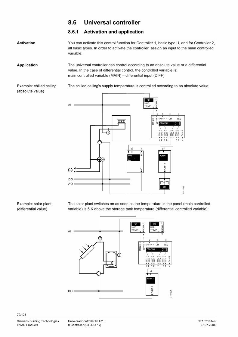
72/128
Siemens Building Technologies Universal Controller RLU2… CE1P3101en
HVAC Products 8 Controller (CTLOOP x) 07.07.2004
8.6 Universal controller
8.6.1 Activation and application
You can activate this control function for Controller 1, basic type U, and for Controller 2,
all basic types. In order to activate the controller, assign an input to the main controlled
variable.
The universal controller can control according to an absolute value or a differential
value. In the case of differential control, the controlled variable is:
main controlled variable (MAIN) – differential input (DIFF)
The chilled ceiling's supply temperature is controlled according to an absolute value:
DO
Q1
M
AO
AI
T
Y
X1
Y
SIG
NA
L Y
LABEL
TEMP
y p y p y p
x xx
DIFF
x
Q
MAIN
LIM SEQ SHIFT
1CTLOOP 1
DV
ALM
SE
Q2 Y
SE
Q2 P
SE
Q1 Y
SE
Q1 P
SE
Q4 Y
SE
Q4 P
SE
Q5 Y
SE
Q5 P
p2
PU
MP
1
PUMP 1
1
y2
IN X
x
A0
AO 1
310
1S
25
The solar plant switches on as soon as the temperature in the panel (main controlled
variable) is 5 K above the storage tank temperature (differential controlled variable):
DO
AI
T
T
Y
X1
Y
SIG
NA
L Y
LABEL
TEMP
y p y p y p
x x
DIFF
x
Q
MAIN
LIM SEQ SHIFT
1CTLOOP 1
DV
ALM
SE
Q2 Y
SE
Q2 P
SE
Q1 Y
SE
Q1 P
SE
Q4 Y
SE
Q4 P
SE
Q5 Y
SE
Q5 P
p2
PU
MP
1
PUMP 1
Y
X2
Y
SIG
NA
L Y
LABEL
TEMP
y
310
1S
28
Activation
Application
Example: chilled ceiling
(absolute value)
Example: solar plant
(differential value)
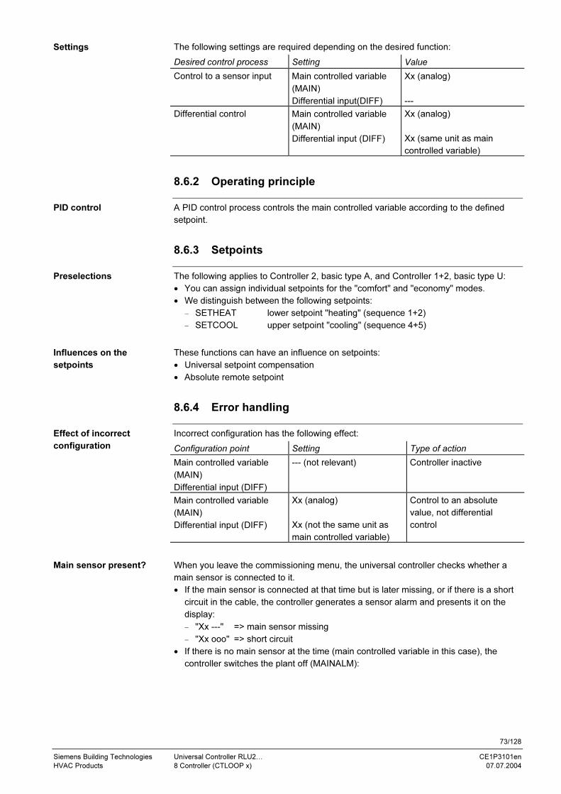
73/128
Siemens Building Technologies Universal Controller RLU2… CE1P3101en
HVAC Products 8 Controller (CTLOOP x) 07.07.2004
The following settings are required depending on the desired function:
Desired control process Setting Value
Control to a sensor input Main controlled variable
(MAIN)
Differential input(DIFF)
Xx (analog)
---
Differential control Main controlled variable
(MAIN)
Differential input (DIFF)
Xx (analog)
Xx (same unit as main
controlled variable)
8.6.2 Operating principle
A PID control process controls the main controlled variable according to the defined
setpoint.
8.6.3 Setpoints
The following applies to Controller 2, basic type A, and Controller 1+2, basic type U:
• You can assign individual setpoints for the "comfort" and "economy" modes.
• We distinguish between the following setpoints:
− SETHEAT lower setpoint "heating" (sequence 1+2)
− SETCOOL upper setpoint "cooling" (sequence 4+5)
These functions can have an influence on setpoints:
• Universal setpoint compensation
• Absolute remote setpoint
8.6.4 Error handling
Incorrect configuration has the following effect:
Configuration point Setting Type of action
Main controlled variable
(MAIN)
Differential input (DIFF)
--- (not relevant) Controller inactive
Main controlled variable
(MAIN)
Differential input (DIFF)
Xx (analog)
Xx (not the same unit as
main controlled variable)
Control to an absolute
value, not differential
control
When you leave the commissioning menu, the universal controller checks whether a
main sensor is connected to it.
• If the main sensor is connected at that time but is later missing, or if there is a short
circuit in the cable, the controller generates a sensor alarm and presents it on the
display:
− "Xx ---" => main sensor missing
− "Xx ooo" => short circuit
• If there is no main sensor at the time (main controlled variable in this case), the
controller switches the plant off (MAINALM):
Settings
PID control
Preselections
Influences on the
setpoints
Effect of incorrect
configuration
Main sensor present?

74/128
Siemens Building Technologies Universal Controller RLU2… CE1P3101en
HVAC Products 8 Controller (CTLOOP x) 07.07.2004
8.6.5 Settings
Path: … > SET
Display Name Range Factory setting
SET MAX Economy setpoint
high
Main controlled
variable input range
28 °C, 80 %, 100, 1000
SET MAX Upper comfort
setpoint
Main controlled
variable input range
24 °C, 60 %, 6, 400
SET MIN Lower comfort
setpoint
Main controlled
variable input range
21 °C, 40 %, 0, 0
SET MIN Economy setpoint
bottom
Main controlled
variable input range
19 °C, 20 %, 0, 0
Path: …> SET
Display Name Range Factory setting
SET MAX Economy setpoint
high
Main controlled
variable input range
28 °C, 80 %, 100, 1000
SET MAX Upper comfort
setpoint
Main controlled
variable input range
24 °C, 60 %, 6, 400
SET MIN Lower comfort
setpoint
Main controlled
variable input range
21 °C, 40 %, 0, 0
SET MIN Economy setpoint
bottom
Main controlled
variable input range
19 °C, 20 %, 0, 0
Controller 1,
basic type U
Controller 2,
basic types A and U

75/128
Siemens Building Technologies Universal Controller RLU2… CE1P3101en
HVAC Products 8 Controller (CTLOOP x) 07.07.2004
8.7 Primary controller (universal) with changeover
8.7.1 Activating the universal controller with changeover
The following example shows a changeover plant with supply area, primary control and
room temperature controls. The RLU2…(U) primary controller and RLU2…(A) room
temperature controller are indicated.
T
T
RLU2...(U)
3101S31
T
T
T TRLU2...(A)
You can activate this control function for all universal controllers, i.e. for RLU210,
RLU222, RLU232 and RLU236 in basic type U.
Apply the following procedure to activate the respective controller:
• Assign one Xx input each to the main controlled variable (MAIN) at the CTLOOPx
controller block and to the CH OVER input at the MODE function block.
• Set the identifier of the main controlled variable (MAIN) to TEMP.
Note: The "Changeover" function always acts on Controller 1 only.
It is also possible to activate the changeover function in the RLU210 controller, basic
type A:
The RLU210 controller operates as a normal room temperature controller, basic type A.
However, the changeover input, which is switched by a changeover thermostat on the
supply side, enables only the heating or cooling sequence at any one time.
8.7.2 Operating principle
A PID control process controls the main controlled variable according to the defined
setpoint.
The position of the CH OVER digital input determines whether the heating sequence or
cooling sequence is enabled:
• CH OVER = 0 signifies "enable cooling sequences"
• CH OVER = 1 signifies "enable heating sequences"
The "analog output" aggregate must be configured for sequences, i.e:
• Heating (sequence 1) and
• Cooling (sequence 4)
See chapter 8.8 Sequence Controllers, Output Assignments for more information.
Plant principle
Activating the RLU2…
(U) primary controller
Room temperature
controller RLU210 (A)
Control type
Sequence enabling
Note

76/128
Siemens Building Technologies Universal Controller RLU2… CE1P3101en
HVAC Products 8 Controller (CTLOOP x) 07.07.2004
8.7.3 Setpoints
You can assign individual setpoints for the "comfort" and "economy" modes.
We distinguish between the setpoints for:
• Primary controller "heating" (sequence 1)
• Primary controller "cooling" (sequence 4)
The following diagrams illustrate the different setpoint preselections for non-changeover
systems and changeover systems:
100 %
28 °C
21 °C
24 °C
19 °C
60 °C
40 °C
10 °C
6 °C
6 °C 60 °C
21 °C 24 °C
100 %
0 %
0 % TR
TW
CMP
CMP
SETHEAT
SETHEAT
SETCOOL
SETCOOL
1D
2D
2END
1END
2STT
1STT
2END1END
1D 2D
2STT1STT
SET MAX
SET MAX
SET MIN
SET MIN
3101D22en
Sequence controller
IndirectHeating
DirectCooling
Sequence controller
IndirectHeating
DirectCooling
Non-changeover system:
Changeover system:
Heating setpoints less than cooling setpointse.g. room temperature control
Heating setpoints greater than coolinge.g. supply temperature control
Economy setpoint, high
Economy setpoint, low
Comfort setpoint, high
Comfort setpoint, low
Comfort heating setpoint
Economy heating setpoint
Economy cooling setpoint
Comfort cooling setpoint
Refer to the corresponding setting values on the following page (factory settings).
Economy setpoints are only adjustable if an input has been defined for mode
changeover.
The following functions can have an influence on setpoints:
• Universal setpoint compensation (see page 91)
• Absolute remote setpoint (see page 29)
Sequence controller 2 always operates in the same mode as sequence controller 1, but
it has no changeover functionality.
Basic type U,
Controller 1
Setpoint preselection
Note on economy
setpoints
Influences on the
setpoints
Basic type U,
Controller 2
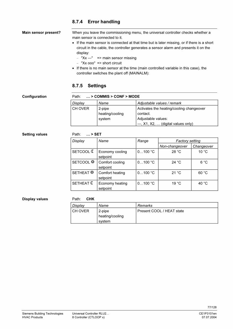
77/128
Siemens Building Technologies Universal Controller RLU2… CE1P3101en
HVAC Products 8 Controller (CTLOOP x) 07.07.2004
8.7.4 Error handling
When you leave the commissioning menu, the universal controller checks whether a
main sensor is connected to it.
• If the main sensor is connected at that time but is later missing, or if there is a short
circuit in the cable, the controller generates a sensor alarm and presents it on the
display:
− "Xx ---" => main sensor missing
− "Xx ooo" => short circuit
• If there is no main sensor at the time (main controlled variable in this case), the
controller switches the plant off (MAINALM):
8.7.5 Settings
Path: … > COMMIS > CONF > MODE
Display Name Adjustable values / remark
CH OVER 2-pipe
heating/cooling
system
Activates the heating/cooling changeover
contact.
Adjustable values:
---, X1, X2, … (digital values only)
Path: … > SET
Factory setting Display Name Range
Non-changeover Changeover
SETCOOL Economy cooling
setpoint
0…100 °C 28 °C 10 °C
SETCOOL Comfort cooling
setpoint
0…100 °C 24 °C 6 °C
SETHEAT Comfort heating
setpoint
0…100 °C 21 °C 60 °C
SETHEAT Economy heating
setpoint
0…100 °C 19 °C 40 °C
Path: CHK
Display Name Remarks
CH OVER 2-pipe
heating/cooling
system
Present COOL / HEAT state
Main sensor present?
Configuration
Setting values
Display values

78/128
Siemens Building Technologies Universal Controller RLU2… CE1P3101en
HVAC Products 8 Controller (CTLOOP x) 07.07.2004
8.7.6 Application examples
Typical application examples for the changeover controller:
• Example 1: Hot/chilled water supply temperature control (basic type U)
• Example 2: Individual room control with air heater/cooler (basic type A)
This example corresponds to application number RLU210 / A11 from the programmed
standard applications:
N.X1
B1
T
3101S32
Y5N.Y1
M
TF16N.X2
T
F3N.X3
N.D1
S5
Y
X1
Y
SIG
NA
L Y
LABEL
TEMP
Y
X2
Y
SIG
NA
L Y
LABEL
DIG
Y
X3
Y
SIG
NA
L Y
LABEL
FRST
x
1
IN X
x
A0
AO 1
Y1
x x
SU
PP
LY
x
LIM SEQ CAS/CON
SE
Q1 Y
SE
Q4 Y
1CTLOOP 1
D1
x
MODE CH
OV
ER
OP
MO
DE
AO
DI
AI
Two typical examples
Diagram for example 2,
individual room control
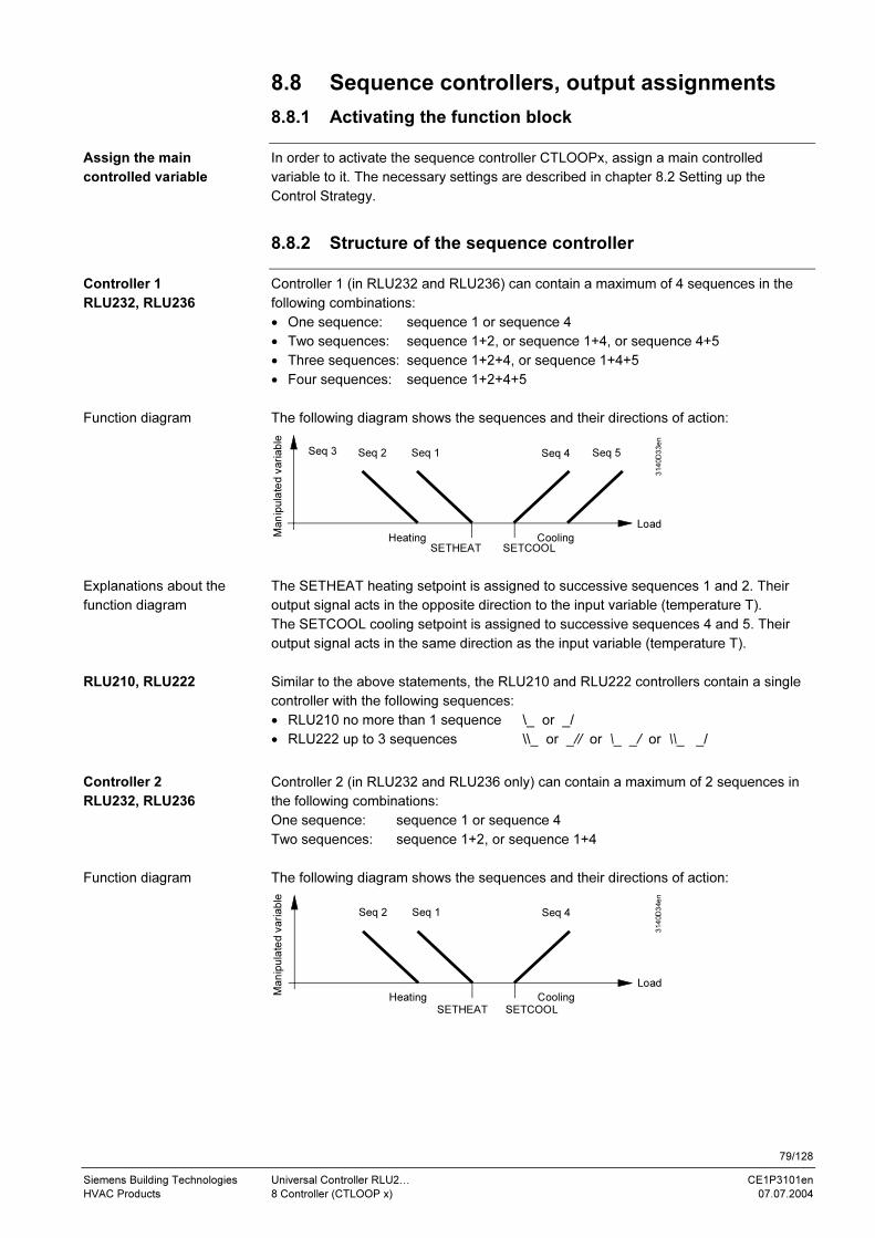
79/128
Siemens Building Technologies Universal Controller RLU2… CE1P3101en
HVAC Products 8 Controller (CTLOOP x) 07.07.2004
8.8 Sequence controllers, output assignments
8.8.1 Activating the function block
In order to activate the sequence controller CTLOOPx, assign a main controlled
variable to it. The necessary settings are described in chapter 8.2 Setting up the
Control Strategy.
8.8.2 Structure of the sequence controller
Controller 1 (in RLU232 and RLU236) can contain a maximum of 4 sequences in the
following combinations:
• One sequence: sequence 1 or sequence 4
• Two sequences: sequence 1+2, or sequence 1+4, or sequence 4+5
• Three sequences: sequence 1+2+4, or sequence 1+4+5
• Four sequences: sequence 1+2+4+5
The following diagram shows the sequences and their directions of action:
SETHEAT SETCOOL
3140D33en
Heating CoolingMan
ipula
ted v
ari
able
Load
Seq 3 Seq 2 Seq 1 Seq 5Seq 4
The SETHEAT heating setpoint is assigned to successive sequences 1 and 2. Their
output signal acts in the opposite direction to the input variable (temperature T).
The SETCOOL cooling setpoint is assigned to successive sequences 4 and 5. Their
output signal acts in the same direction as the input variable (temperature T).
Similar to the above statements, the RLU210 and RLU222 controllers contain a single
controller with the following sequences:
• RLU210 no more than 1 sequence \_ or _/
• RLU222 up to 3 sequences \\_ or _// or \_ _/ or \\_ _/
Controller 2 (in RLU232 and RLU236 only) can contain a maximum of 2 sequences in
the following combinations:
One sequence: sequence 1 or sequence 4
Two sequences: sequence 1+2, or sequence 1+4
The following diagram shows the sequences and their directions of action:
SETHEAT SETCOOL
3140D34en
Heating Cooling
Man
ipula
ted v
ari
able
Load
Seq 2 Seq 1 Seq 4
Assign the main
controlled variable
Controller 1
RLU232, RLU236
Function diagram
Explanations about the
function diagram
RLU210, RLU222
Controller 2
RLU232, RLU236
Function diagram
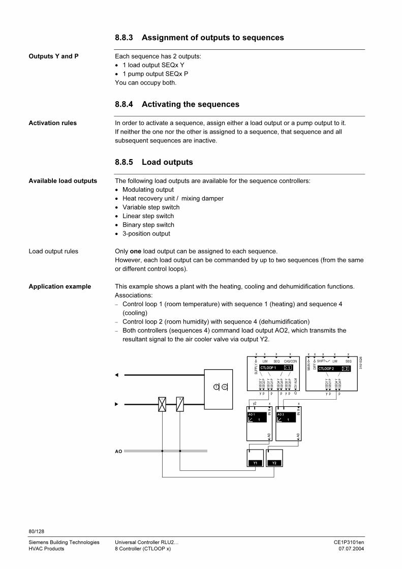
80/128
Siemens Building Technologies Universal Controller RLU2… CE1P3101en
HVAC Products 8 Controller (CTLOOP x) 07.07.2004
8.8.3 Assignment of outputs to sequences
Each sequence has 2 outputs:
• 1 load output SEQx Y
• 1 pump output SEQx P
You can occupy both.
8.8.4 Activating the sequences
In order to activate a sequence, assign either a load output or a pump output to it.
If neither the one nor the other is assigned to a sequence, that sequence and all
subsequent sequences are inactive.
8.8.5 Load outputs
The following load outputs are available for the sequence controllers:
• Modulating output
• Heat recovery unit / mixing damper
• Variable step switch
• Linear step switch
• Binary step switch
• 3-position output
Only one load output can be assigned to each sequence.
However, each load output can be commanded by up to two sequences (from the same
or different control loops).
This example shows a plant with the heating, cooling and dehumidification functions.
Associations:
− Control loop 1 (room temperature) with sequence 1 (heating) and sequence 4
(cooling)
− Control loop 2 (room humidity) with sequence 4 (dehumidification)
− Both controllers (sequences 4) command load output AO2, which transmits the
resultant signal to the air cooler valve via output Y2.
Y1 Y2
AO
TϕT
y p p p y p
x xx x
Q
LIM SEQ CAS/CON
1CTLOOP 1
SE
Q2 Y
SE
Q2 P
SE
Q1 Y
SE
Q1 P
SE
Q4 Y
SE
Q4 P
SE
Q5 Y
SE
Q5 P
DV
ALM
SUPPLY
1
y2
IN X
x
A0
AO 1
1
IN X
x
A0
AO 2
y p p
x x xx
DIFF
x
MAIN
LIM SEQ SHIFT
2CTLOOP 2
SE
Q1
Y
SE
Q1
P
SE
Q4
Y
SE
Q4
P
3101S26
Outputs Y and P
Activation rules
Available load outputs
Load output rules
Application example

81/128
Siemens Building Technologies Universal Controller RLU2… CE1P3101en
HVAC Products 8 Controller (CTLOOP x) 07.07.2004
8.8.6 Pump outputs
Only one pump can be assigned to each sequence. However, each pump can be
commanded by up to two sequences.
This example shows an air heater with a valve and pump. Both are commanded by
sequence 1; the pump is commanded via the pump output SEQ2 P:
Y1
DO
Q1
AO
p
x x xx
DIFF
x
Q
MAIN
LIM SEQ SHIFT
2CTLOOP 2
DV
ALM
SE
Q2 Y
SE
Q2 P
SE
Q1 Y
SE
Q1 P
1
y2
IN X
x
A0
AO 1
p2
PU
MP
1
PUMP 1
y
310
1S
27
8.8.7 Control parameters (Xp, Tn, Tv)
You can define the following control parameters for each configured sequence:
• SEQx XP (P-band Xp)
• SEQx TN (Integral-action time Tn)
• SEQx TV (Derivative-action time Tv)
If you use all parameters, the result is a PID control loop.
If you want P, PI or PD control action, make the following settings:
Setting Result
SEQx TN = 00:00; SEQx TV = 00:00 P action
SEQx TV = 00:00 PI action
SEQx TN = 00:00 PD action
We recommend the following standard values for quick controller commissioning:
• P-band Xp of the controller:
Room and exhaust air control loops 1…2 K / 2…4 % r.h.,
supply air control loops 5 K / 10 % r.h.
• Set the integral-action time Tn equal to the greatest time constant of the controlled
system.
• Set the derivative-action time Tv equal to the time constant of the sensor.
Apply the following procedure if the control loop oscillates:
1. Set Tn and Tv to 00:00.
2. Increase Xp (e.g. double it)
3. Add Tn again, starting with the value shown above.
Increase Tn if the control loop starts to oscillate again.
4. Add Tv again, starting with the value shown above.
Reduce Tv if the control loop starts to oscillate again.
Possibilities
Application example
Setting possibilities
Recommendations for
commissioning
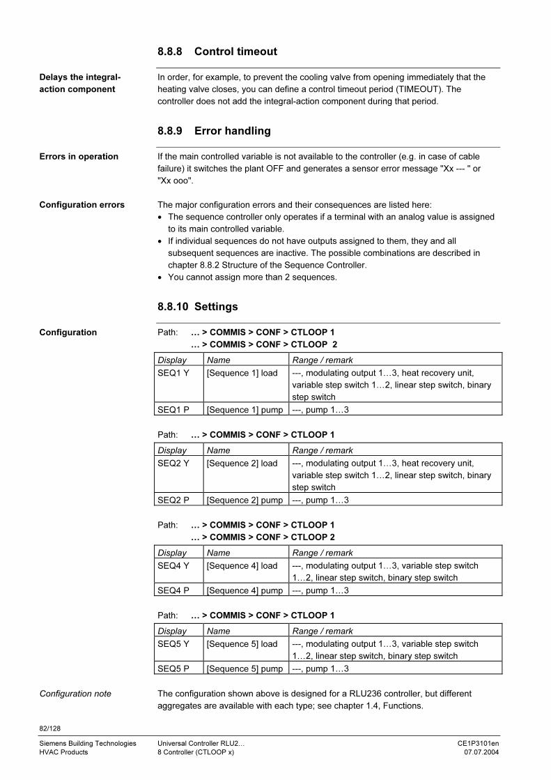
82/128
Siemens Building Technologies Universal Controller RLU2… CE1P3101en
HVAC Products 8 Controller (CTLOOP x) 07.07.2004
8.8.8 Control timeout
In order, for example, to prevent the cooling valve from opening immediately that the
heating valve closes, you can define a control timeout period (TIMEOUT). The
controller does not add the integral-action component during that period.
8.8.9 Error handling
If the main controlled variable is not available to the controller (e.g. in case of cable
failure) it switches the plant OFF and generates a sensor error message "Xx --- " or
"Xx ooo".
The major configuration errors and their consequences are listed here:
• The sequence controller only operates if a terminal with an analog value is assigned
to its main controlled variable.
• If individual sequences do not have outputs assigned to them, they and all
subsequent sequences are inactive. The possible combinations are described in
chapter 8.8.2 Structure of the Sequence Controller.
• You cannot assign more than 2 sequences.
8.8.10 Settings
Path: … > COMMIS > CONF > CTLOOP 1
… > COMMIS > CONF > CTLOOP 2
Display Name Range / remark
SEQ1 Y [Sequence 1] load ---, modulating output 1…3, heat recovery unit,
variable step switch 1…2, linear step switch, binary
step switch
SEQ1 P [Sequence 1] pump ---, pump 1…3
Path: … > COMMIS > CONF > CTLOOP 1
Display Name Range / remark
SEQ2 Y [Sequence 2] load ---, modulating output 1…3, heat recovery unit,
variable step switch 1…2, linear step switch, binary
step switch
SEQ2 P [Sequence 2] pump ---, pump 1…3
Path: … > COMMIS > CONF > CTLOOP 1
… > COMMIS > CONF > CTLOOP 2
Display Name Range / remark
SEQ4 Y [Sequence 4] load ---, modulating output 1…3, variable step switch
1…2, linear step switch, binary step switch
SEQ4 P [Sequence 4] pump ---, pump 1…3
Path: … > COMMIS > CONF > CTLOOP 1
Display Name Range / remark
SEQ5 Y [Sequence 5] load ---, modulating output 1…3, variable step switch
1…2, linear step switch, binary step switch
SEQ5 P [Sequence 5] pump ---, pump 1…3
The configuration shown above is designed for a RLU236 controller, but different
aggregates are available with each type; see chapter 1.4, Functions.
Delays the integral-
action component
Errors in operation
Configuration errors
Configuration
Configuration note

83/128
Siemens Building Technologies Universal Controller RLU2… CE1P3101en
HVAC Products 8 Controller (CTLOOP x) 07.07.2004
Path: … > PARA > CTLOOP 1
… > PARA > CTLOOP 2
Display Name Range Factory setting
SEQ1 XP [Sequence 1 \_ ] Xp 0…500 K 30 K
SEQ1 TN [Sequence 1 \_ ] Tn 00.00…60.00 m.s 03.00 m.s
SEQ1 TV [Sequence 1 \_ ] Tv 00.00…60.00 m.s 00.00 m.s
SEQ2 XP [Sequence 2 \ .._ ] Xp 0…500 K 30 K
SEQ2 TN [Sequence 2 \ .._ ] Tn 00.00…60.00 m.s 03.00 m.s
SEQ2 TV [Sequence 2 \ .._ ] Tv 00.00…60.00 m.s 00.00 m.s
SEQ4 XP [Sequence 4 _/ ] Xp 0…500 K 30 K
SEQ4 TN [Sequence 4 _/ ] Tn 00.00…60.00 m.s 03.00 m.s
SEQ4 TV [Sequence 4 _/ ] Tv 00.00…60.00 m.s 00.00 m.s
SEQ5 XP [Sequence 5 _.. / ] Xp 0…500 K 30 K
SEQ5 TN [Sequence 5 _.. / ] Tn 00.00…60.00 m.s 03.00 m.s
SEQ5 TV [Sequence 5 _.. / ] Tv 00.00…60.00 m.s 00.00 m.s
TIMEOUT Control timeout 00.00…60.00 m.s 00.00 m.s
Path: Info
Display Name Remarks
\_ [Sequence 1] load output Indicates the sequence controller's
present output as 0…100 % with a
sequence diagram and controller icon
\ \_ [Sequence 2] load output See above remark
_/ [Sequence 4] load output See above remark
_/ / [Sequence 5] load output See above remark
Setting values
Display values

84/128
Siemens Building Technologies Universal Controller RLU2… CE1P3101en
HVAC Products 8 Controller (CTLOOP x) 07.07.2004
8.9 Limit control, general (LIM)
8.9.1 Purpose and activation
The LIM function (general limit controller) overrides the sequence controller's normal
control function.
In order to activate the function, you have to assign an input Xx to the LIM connection
of the CTLOOP function block.
If other influences act on the sequence controller at the same time, the order of
priorities applies as shown in chapter 8.1.4, Function Priorities.
8.9.2 Operating principle
If a controlled variable goes above or below the limit setpoint, the limit controller
overrides the normal control function with a PI response (LIM XP, LIM TN) to ensure
compliance with the limit setpoint. We distinguish between:
• Absolute limit control
• Relative limit control
If you only want one of these functions, you can disable the other by setting the
setpoints a long way out of range.
You can define one setpoint each for high-limit and low-limit control (LIM MAX,
LIM MIN).
Supply air temperature or supply air humidity limit control:
x
w
T
T
[LIM MAX]
[LIM MIN]
− [LIM COOL]
Limitation max
Limitation min
3101S33en
Acts an all sequences
!! Not meaningful with cascade control !!
Setpoint adjustment
If cooling sequence 4+5 is enabled, the low-limit control can be set lower by an
adjustable value (LIMCOOL). This feature prevents the refrigeration machine from
switching off again shortly after switching on in case of stepped (DX) cooling.
It is only active if the main controlled variable and the general limit control input have
the unit °C.
The following applies to relative limit control:
• You can only activate high and low differential limit control (LIM DHI, LIM DLO) if the
main controlled variable and limit control sensor are configured with the same
physical unit.
• The defined limit control setpoints refer to the temperature difference between the
main controlled variable and the limit control sensor.
• You can define one setpoint each for high-limit and low-limit differential temperature
control.
Purpose of LIM
Activation
Limit controller with
PI response
Absolute limit control
Application example
Special case:
Cooling sequence 4+5
active
Relative limit control

85/128
Siemens Building Technologies Universal Controller RLU2… CE1P3101en
HVAC Products 8 Controller (CTLOOP x) 07.07.2004
Supply air temperature limit control for a displacement ventilation outlet:
1,5
m
w
w
x
x
T
T
x
w
[LIM DHI]
[LIM DLO]
Limitation max
Limitation min
3101S34en
Acts an all sequences
!! Not meaningful with cascade control !!
Setpoint adjustment
8.9.3 Error handling
When you leave the commissioning menu, the universal controller checks whether a
sensor is connected to the LIM input.
• If a sensor is connected at that time but is later missing, the controller generates a
sensor alarm, and presents it on the display:
− "Xx ---" => sensor missing
− "Xx ooo" => short circuit
• If no sensor is connected at the time, the limit control function is disabled.
8.9.4 Settings
Path: … > COMMIS > CONF > CTLOOP 1
… > COMMIS > CONF > CTLOOP 2
Display Name Range / remark
LIM General limit
controller
Activates general limit control; adjustable values: ---, X1,
X2, … (analog values only)
Path: … > PARA > CTLOOP 1
… > PARA > CTLOOP 2
Display Name Range Factory setting
LIM MAX Gen limiter limit
value high
Limit control sensor input range 35 °C
LIM MIN Gen limiter limit
value low
Limit control sensor input range 16 °C
LIM DHI Gen limiter
differential high
0…100 K 50 K
LIM DLO Gen limiter
differential low
0…100 K 50 K
LIMCOOL Reduction min
limitation cooling
0…10 K 0 K
LIM XP Gen limiter P-
band Xp
15 K
LIM TN Gen limiter
integr action
time Tn
00.00…60.00 m.s 02.00 m.s
Application example
Limit control sensor
connected?
Configuration
Setting values

86/128
Siemens Building Technologies Universal Controller RLU2… CE1P3101en
HVAC Products 8 Controller (CTLOOP x) 07.07.2004
8.10 Limit control of individual sequences (SEQ)
8.10.1 Purpose and activation
The SEQ provides limit control for individual sequences.
In order to activate this function, configure the SEQ input of the CTLOOP controller.
The following applies:
• You can only assign analog inputs.
• You can only activate this function once per controller.
• If other influences act on the sequence controller at the same time, the order of
priorities applies as shown in chapter 8.1.4, Function Priorities.
8.10.2 Operating principle
This function is configurable either for low-limit control or for high-limit control. You can
assign its action to one of the sequences (Seq 1, Seq 2, … Seq 5):
3101D03
x2
w2
CTL1
1
ymax
x1
w1
Legend:
x2 Limit controlled variable
w2 Limit control setpoint (min/max)
ymax Limit control signal; always acts in close direction
on 1 sequence (Seq1, Seq2…Seq5)
x1 Main controlled variable
w1 Main setpoint
CTL1 Controller 1 (CTLOOP1)
If a controlled variable goes below the limit control setpoint (SEQ SET), the limit
controller overrides the normal control function with a PI response (SEQ XP, SEQ TN)
to ensure compliance with the limit setpoint.
The low-limit control acts in the close direction on the respective sequences; it has no
effect on the other sequences.
Frost protection for a heat recovery unit (HRU), acting in close direction on sequence 1
(Y6)
The temperature at limit control sensor B21 must, for example, be at least 0 °C
(SEQ SET), otherwise throughput will be steplessly limited by Y6.
Pictorial schematic Function diagram
M
M6
Y6
T
T
MY3
M3
3101S35
B21
Yctl
1
0TSu
3101D04
M3
Y6
Y3
M6
SpTSuH
Purpose of SEQ
Activation
General function
Low-limit control
Application example, HRU

87/128
Siemens Building Technologies Universal Controller RLU2… CE1P3101en
HVAC Products 8 Controller (CTLOOP x) 07.07.2004
Low-limit control of the water inlet temperature (B7) in a boiler with corrosion risk,
acting on sequence 1 (Y3):
M
T
T
N.X1
B1
Y3N.Q1
N.Q2
N.X2
B7
3101S36
If a controlled variable goes above the limit control setpoint (SEQ SET), the limit
controller overrides the normal control function with a PI response (SEQ XP, SEQ TN)
to ensure compliance with the limit setpoint.
The high-limit control function acts in the close direction on the sequences.
High-limit control of the return temperature (TRL), acting on sequence 1 / valve M:
Pictorial schematic Function diagram
T B1
T
M
TRL
3101S37
M6
Yctl
1
0TSu
3101D06
SpTSuH
M6
SEQ1 Y
8.10.3 Error handling
When you leave the commissioning menu, the universal controller checks whether a
sensor is connected to it.
• If the sensor is connected at that time but is later missing, or if there is a short circuit
in the cable, the controller generates a sensor alarm and presents it on the display:
− "Xx ---" => sensor missing
− "Xx ooo" => short circuit
• If the sensor is not connected at the time, the limit control function is disabled.
Application example,
boiler
High-limit control
Application example,
air heater
Sensor connected?

88/128
Siemens Building Technologies Universal Controller RLU2… CE1P3101en
HVAC Products 8 Controller (CTLOOP x) 07.07.2004
8.10.4 Settings
Path: … > COMMIS > CONF > CTLOOP 1
… > COMMIS > CONF > CTLOOP 2
Display Name Range / remark
SEQ Sequence limit controller Activates the limit control of an individual
sequence; adjustable values:
---, X1, X2, … (analog values only)
Path: … > PARA > CTLOOP 1
… > PARA > CTLOOP 2
Display Name Range Factory setting
SEQ MOD Type of limitation Min, Max Min
SEQ SEL Sequence selection Seq1, Seq2, Seq4, Seq5 Seq1
SEQ SET Limit value Input signal range 1 °C
SEQ XP Seq limiter P-band Xp Input signal range 10 K
SEQ TN Seq limiter integr action
time Tn
00.00…60.00 mm.ss 02.00 m.s
Configuration
Setting values

89/128
Siemens Building Technologies Universal Controller RLU2… CE1P3101en
HVAC Products 8 Controller (CTLOOP x) 07.07.2004
8.11 Locking of sequences according to outside temperature
8.11.1 Purpose and activation
This function disables individual sequences depending on the outside temperature.
This function is always active if an outside temperature value is available.
If other influences act on the sequence controller at the same time, the order of
priorities applies as shown in chapter 8.1.4, Function Priorities.
8.11.2 Operating principle
You can lock heating sequences at a higher outside temperature and cooling
sequences at a lower outside temperature. This ensures that heating is deactivated in
summer and cooling is deactivated in winter. The switching differential is fixed at 2 K
Summer: Winter:
Seq. 1
1
0TALOCK S1
1
0TA
3101D12Seq. 4
LOCK S4
2 K2 K
1 = sequence enabled
0 = sequence disabled
If individual sequences are disabled, the controller continues its action with the other
sequences without a transition.
If, for example, sequence 1 is disabled, then the controller uses sequence 2 for heating
(sequence 1 does not delay the control process).
8.11.3 Error handling
If there is no outside temperature sensor signal, the controller does not disable the
sequences.
8.11.4 Settings
Path: … > PARA > CTLOOP 1
… > PARA > CTLOOP 2
Display Name Range Factory setting
LOCK S1 [Sequence 1] outside temp > −50…+250 °C 250 °C
LOCK S2 [Sequence 2] outside temp > −50…+250 °C 250 °C
LOCK S4 [Sequence 4] outside temp < −50…+150 °C −50 °C
LOCK S5 [Sequence 5] outside temp < −50….+150 °C −50 °C
8.11.5 Application example
Disable a preheater on sequence 2 at temperatures above 10 °C. Function:
valve closed, pump off
Purpose
Activation
Summer and winter
cases
Explanation
Response if individual
sequences are disabled
OT sensor signal
available?
Setting values
Preheater
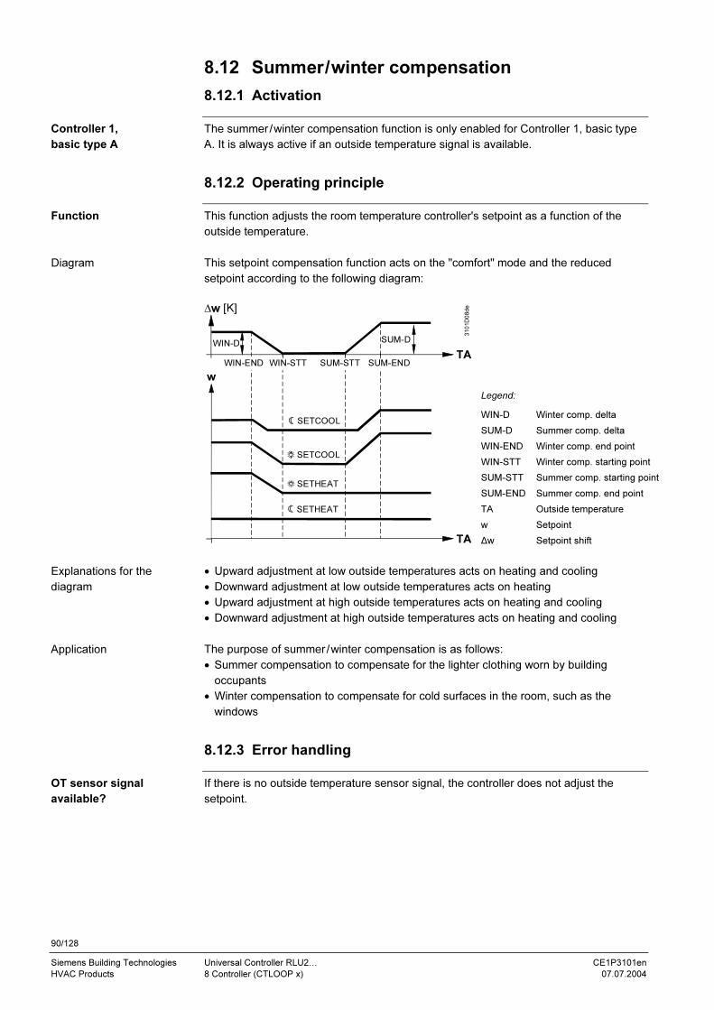
90/128
Siemens Building Technologies Universal Controller RLU2… CE1P3101en
HVAC Products 8 Controller (CTLOOP x) 07.07.2004
8.12 Summer/winter compensation
8.12.1 Activation
The summer/winter compensation function is only enabled for Controller 1, basic type
A. It is always active if an outside temperature signal is available.
8.12.2 Operating principle
This function adjusts the room temperature controller's setpoint as a function of the
outside temperature.
This setpoint compensation function acts on the "comfort" mode and the reduced
setpoint according to the following diagram:
w
∆w [K]
SUM-ENDSUM-STTWIN-END WIN-STT
SETCOOL
SETCOOL
SETHEAT
SETHEAT
SUM-DWIN-D
3101D08de
TA
TA
Legend:
WIN-D Winter comp. delta
SUM-D Summer comp. delta
WIN-END Winter comp. end point
WIN-STT Winter comp. starting point
SUM-STT Summer comp. starting point
SUM-END Summer comp. end point
TA Outside temperature
w Setpoint
∆w Setpoint shift
• Upward adjustment at low outside temperatures acts on heating and cooling
• Downward adjustment at low outside temperatures acts on heating
• Upward adjustment at high outside temperatures acts on heating and cooling
• Downward adjustment at high outside temperatures acts on heating and cooling
The purpose of summer/winter compensation is as follows:
• Summer compensation to compensate for the lighter clothing worn by building
occupants
• Winter compensation to compensate for cold surfaces in the room, such as the
windows
8.12.3 Error handling
If there is no outside temperature sensor signal, the controller does not adjust the
setpoint.
Controller 1,
basic type A
Function
Diagram
Explanations for the
diagram
Application
OT sensor signal
available?

91/128
Siemens Building Technologies Universal Controller RLU2… CE1P3101en
HVAC Products 8 Controller (CTLOOP x) 07.07.2004
8.12.4 Settings
Path: … > PARA > CTLOOP 1
Factory setting Display Name Range
SUM-D Summer compensation delta 0 K
SUM-END Summer compensation end 30 °C
SUM-STT Summer compensation start 20 °C
WIN-STT Winter compensation start 0 °C
WIN-END Winter compensation end −10 °C
WIN-D Winter compensation delta 0 K
8.13 Universal setpoint shift
8.13.1 Activation
This universal setpoint compensation function is available in:
• Controller 1, basic type U only
• Controller 2
In order to activate the function, configure an appropriate output. You can only assign
analog inputs.
8.13.2 Operating principle
You can use a universal input to adjust the controller's setpoint.
This setpoint compensation function acts on the "comfort" and "economy" modes
according to the following diagram:
3101D09
SETCOOL
SETHEAT
∆w [K]
AI
w
CMP1END CMP2ENDCMP1STT CMP2STT
CMP2D
CMP1D
AI
Legend:
AI Analog input
w Setpoint
∆w Setpoint shift
Typical applications for the universal setpoint shift are:
• Refrigeration: adjustment of the supply temperature setpoint for a chilled ceiling
according to room enthalpy or surface temperature
• Ventilation: adjustment according to room humidity or surface temperature
Setting values
Controller 1, basic
type U
Controller 2
Function
Diagram
Application
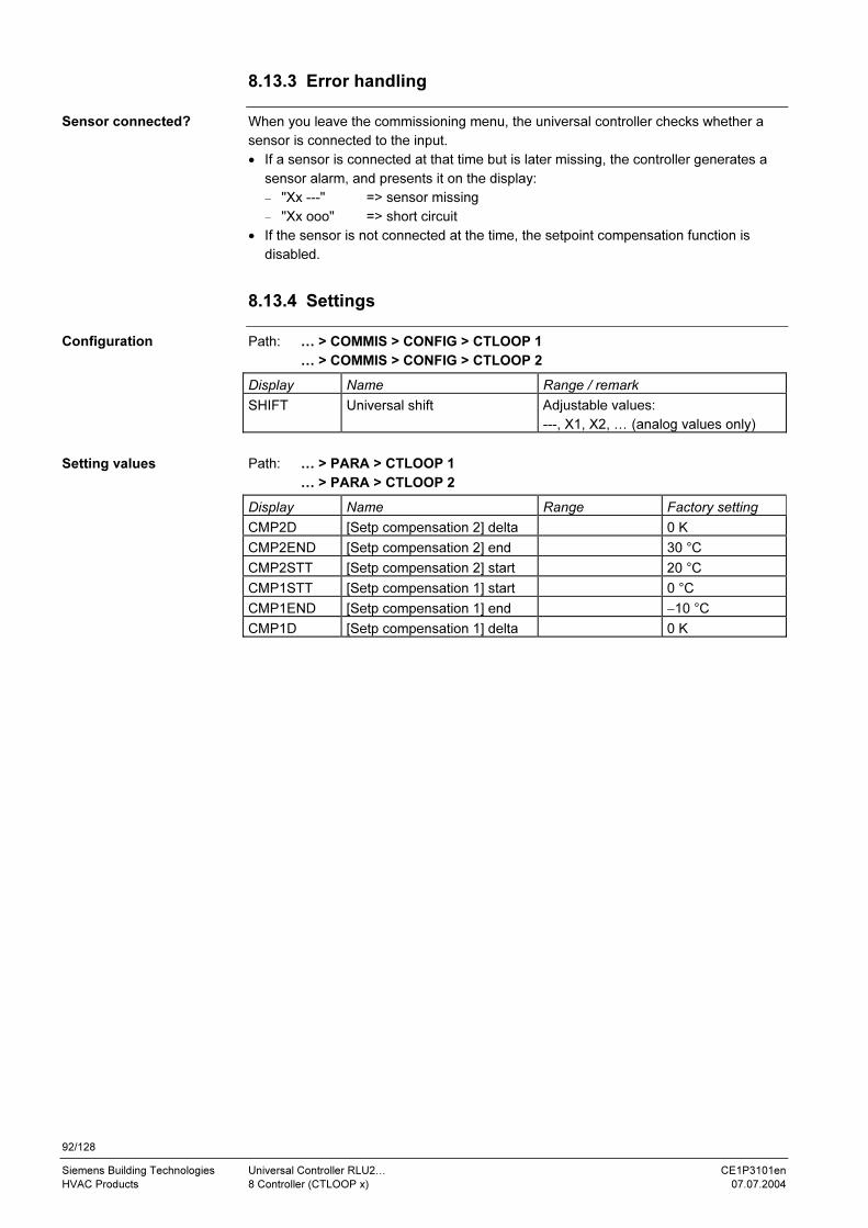
92/128
Siemens Building Technologies Universal Controller RLU2… CE1P3101en
HVAC Products 8 Controller (CTLOOP x) 07.07.2004
8.13.3 Error handling
When you leave the commissioning menu, the universal controller checks whether a
sensor is connected to the input.
• If a sensor is connected at that time but is later missing, the controller generates a
sensor alarm, and presents it on the display:
− "Xx ---" => sensor missing
− "Xx ooo" => short circuit
• If the sensor is not connected at the time, the setpoint compensation function is
disabled.
8.13.4 Settings
Path: … > COMMIS > CONFIG > CTLOOP 1
… > COMMIS > CONFIG > CTLOOP 2
Display Name Range / remark
SHIFT Universal shift Adjustable values:
---, X1, X2, … (analog values only)
Path: … > PARA > CTLOOP 1
… > PARA > CTLOOP 2
Display Name Range Factory setting
CMP2D [Setp compensation 2] delta 0 K
CMP2END [Setp compensation 2] end 30 °C
CMP2STT [Setp compensation 2] start 20 °C
CMP1STT [Setp compensation 1] start 0 °C
CMP1END [Setp compensation 1] end −10 °C
CMP1D [Setp compensation 1] delta 0 K
Sensor connected?
Configuration
Setting values

93/128
Siemens Building Technologies Universal Controller RLU2… CE1P3101en
HVAC Products 8 Controller (CTLOOP x) 07.07.2004
8.14 Deviation message (DV ALM)
8.14.1 Activation
The main controlled variable MAIN or SUPPLY of an RLU2… universal controller can
generate a deviation message.
In order to activate the function, connect the DV ALM output of the controller function
block to any Q… switch output of the RLU2… controller.
y p p p y p
x xx x
Q
LIM SEQ CAS/CON
1CTLOOP 1
SE
Q2 Y
SE
Q2 P
SE
Q1 Y
SE
Q1 P
SE
Q4 Y
SE
Q4 P
SE
Q5 Y
SE
Q5 P
DV
AL
M
SUPPLY
y y
Q1...
3101Z17
The universal controllers of type RLU232 and RLU236 also only have one deviation
signal relay. Both the CTLOOP 1 and CTLOOP 2 sequence controllers always act on
the same relay.
8.14.2 Operating principle
The deviation message monitors the following values:
• Difference between present value and setpoint
• Sequence controller at limit
• Alarm delay time
If a control loop is operating at the limit (all heating sequences fully open and all cooling
sequences fully closed, or vise versa) and the set difference between the present value
and setpoint is exceeded, the controller triggers an alarm after a definable period of
time.
You can set individual alarm delay times for the upper and lower limits. Therefore, you
can also use this function to monitor plants that only heat or only cool.
The controller presents the deviation message as an alarm at the information level like
this:
• Bell icon flashes
• Sequence controller 1 icon is visible
• Indication whether the deviation occurred in the heating or cooling sequences
INFO SERVICE
1
Note the following points with regard to the deviation message:
• Set the alarm delay time long enough so that the plant does not trigger alarms on
startup.
• The deviation message always refers to the sequence controller. Therefore, in the
case of room/supply air temperature cascade control, it monitors the supply air. Set
the values accordingly.
• The deviation message only works when the control process is enabled.
1 deviation signal relay
per universal controller
Note
Monitored values
Trigger
Presentation
Use and configuration
notes

94/128
Siemens Building Technologies Universal Controller RLU2… CE1P3101en
HVAC Products 8 Controller (CTLOOP x) 07.07.2004
• If a sequence is limited by general or sequence limit control, it will not generate a
deviation message.
• The assignment is made in the configuration diagram, always at sequence
controller 1.
• If you set both the deviation message and the timeout period for the sequence
controller, ensure that the alarm delay time for the deviation message is longer than
the timeout period.
If you fail to do so, there will be a deviation message every time the timeout acts on
the sequence controller.
8.14.3 Settings
Path: … > COMMIS > CONF > CTLOOP 1
Display Name Range / remark
DV ALM deviation message Activates the deviation signal function;
adjustable values:
---, Q1, Q2, … (relays only)
Path: … > PARA > CTLOOP 1
… > PARA > CTLOOP 2
Display Name Range Factory setting
DV ALM deviation message Main controlled variable
input signal range
100 K, 100 %, 900.0,
9000
DV DLYH Deviation message
delay high
00.00…6.00 h.m 00.30 h.m
DV DLYL Deviation messagel
delay low
00.00…6.00 h.m 00.30 h.m
Path: CHK
Display Name Remarks
DV ALM Deviation message Indication of present state:
OFF, ON
Path: … > COMMIS > TEST
Display Name Positions
DV ALM Deviation message OFF, ON
8.14.4 Application example
Basic type U / supply temperature control for chilled water:
With an upward adjustment of the setpoint, the water can take a very long time to warm
up if the valves are closed and the pipe is well insulated.
The upper alarm delay time (DV DLYH) is set to 6 h in this case in order to avoid
unnecessary alarms.
If the setpoint deviation is still present after 6 hours, you can assume that the valves do
not close properly.
Configuration
Setting values
Display values
Wiring test
Chilled water supply
temperature control
Necessary delay time
Note

95/128
Siemens Building Technologies Universal Controller RLU2… CE1P3101en
HVAC Products 9 Frost protection (FROST) 07.07.2004
9 Frost protection (FROST)
9.1 Purpose and types of monitoring
The FROST (frost protection) function block protects hot-water air heaters against
freezing.
This function is available only once in all devices. It provides for the following types of
frost protection monitoring:
• Frost protection unit (DIG)
• 2-stage frost protection on the air side (0-10)
• 2-stage frost protection on the water side (NI)
Please note that frost protection control cannot protect the plant against frost damage if
there is insufficient heat output (e.g. no heating water)!
9.2 Activating the function block
In order to activate this function, configure the identifier (LABEL) of an input as frost
(FRST).
The TYPE (identification) setting defines the monitor or sensor used for frost detection.
One of the following frost protection functions becomes active depending on the setting:
Setting Frost protection function
"DIG" Frost protection unit
"0-10" 2-stage frost protection on the air side with active signal
DC 0…10 V = 0…15 °C.
"NI" 2-stage frost protection on the water side, frost protection sensor with
LG-Ni 1000 passive signal
Note the following points with regard to planning and activation of the frost protection
function:
• It must be possible to switch off the fans in case of frost hazard. You can configure a
fan release relay (RELEASE) for this purpose. We recommend configuring function
block output Q to controller output Q1 with:
− Changeover contact Q11-Q14 closed => fan release
− Changeover contact Q11-Q14 open => frost hazard
• For proper functioning of the 2-stage, water-side prost protection function, there must
be an air heater pump. If you want to switch it on via the controller, the outside
temperature signal must be available.
• Additionally, the controller assigned to the frost protection function must be the one
to which the air heater at risk from frost is connected.
• If other influences act on the sequence controller at the same time, the order of
priorities applies as shown in chapter 8.1.4, Function Priorities.
Purpose of FROST
Types of frost protection
monitoring
Note
Configuration
Setting
Notes

96/128
Siemens Building Technologies Universal Controller RLU2… CE1P3101en
HVAC Products 9 Frost protection (FROST) 07.07.2004
9.3 Settings
Path: … > COMMIS > CONF > X…
Display Name Range / remark
LABEL Input identifier Activates the function with the assignment of the
value FRST (frost protection) to the input.
Path: … > PARA > FROST
Display Name Range Factory setting
TYPE Identification Monitor (DIG), air side (0-10),
water side (NI)
DIG
9.4 Operating principle
9.4.1 Frost protection unit (DIG)
This picture shows an application with an air or water-side frost protection unit:
T
T
DI
310
1S
22
X1
x Y
SIG
NA
L Y
LABEL
FRST
Reliable frost protection depends on correct sensor placement.
If the temperature falls below the set limit value, the frost protection unit transmits a
signal to the controller. Meanings:
• Monitor contact (Q11-Q14 / terminals 1-3) closed: no frost hazard
• Monitor contact (Q11-Q14 / terminals 1-3) open: Frost hazard
A frost hazard signal triggers the following actions:
• The fan release relay is de-energized (fan not enabled).
• The control loop configured with the air heater at risk from frost switches off all
cooling sequences, and opens all heating sequences to 100 %. It also switches the
air heater pump on.
=> important: step switches also switch on in the process!
• If two controllers are configured in the RLU2…, the second (other) control loop
switches off.
• The heat recovery unit switches off, and the outdoor air damper closes.
The frost protection function with frost protection unit is activated in all operating modes
(comfort, economy, protection). Therefore, it also overrides limit controls and interlocks
based on the outside temperature!
Configuration
Setting values
Application example
Note
Frost protection control
functions
Note

97/128
Siemens Building Technologies Universal Controller RLU2… CE1P3101en
HVAC Products 9 Frost protection (FROST) 07.07.2004
9.4.2 2-stage frost protection on the air side (0-10)
This picture shows an application with 2-stage, air-side frost protection:
310
1S
23
T
AI
X1
x Y
SIG
NA
L Y
LABEL
FRST
Reliable frost protection depends on correct sensor placement.
The temperature going below the starting point (= limit value + 2 K + P-band) produces
the following reactions:
• The controller steplessly opens all heating sequences and steplessly closes all
cooling sequences.
• The air heater pump switches on.
The purpose is to prevent the temperature from falling below the "frost hazard" limit
value (SET-ON).
If the temperature still goes below the above limit value, the following reactions take
place:
• The fan release relay is de-energized (fan not enabled).
• The control loop configured with the air heater at risk from frost switches off all
cooling sequences, and opens all heating sequences to 100 %. It also switches the
air heater pump on.
=> important: step switches also operate!
• If two controllers are configured in the RLU2…, the second (other) control loop is
switched off.
• The heat recovery unit switches off, and the outdoor air damper closes.
This diagram illustrates the above statements:
100 %
0 %
Xp
5 %
Xp/22 K
SET-ON
TFrst
3101D13en
On
Off
Heat valve
Heating coil pumpFrost alarm
Legend:
SET-ON Frost hazard limit
value TFrst Frost temperature Xp P-band
The frost protection function remains active when the plant is off.
Application example
Note
Temperature goes below
starting point
Reactions if temperature
goes below limit value
Function diagram
Note

98/128
Siemens Building Technologies Universal Controller RLU2… CE1P3101en
HVAC Products 9 Frost protection (FROST) 07.07.2004
9.4.3 2-stage frost protection on the water side (NI)
This picture shows an application with 2-stage, water-side frost protection:
AI
310
1S
24
X1
x Y
SIG
NA
L Y
LABEL
FRST
Observe the following points with regard to sensor placement and the heating circuit
pump:
• Reliable frost protection depends on correct sensor placement.
Position the sensor in or on the water-side outlet of the air heater within the air duct.
• As an additional protection function, the heating circuit pump must switch on
automatically at outside temperatures below 5 °C (setting value "switch-on according
to outside temperature", see chapter 7.1 Pump (PUMP x).
If the temperature going below the starting point (= limit value + 2 K + P-band) the
controller steplessly opens all heating sequences and steplessly closes all cooling
sequences. The purpose is to prevent the temperature from falling below the "risk of
frost limit" (SET-ON).
If the temperature still goes below the above limit value, the following reactions take
place:
• The fan release relay is de-energized (fan not enabled).
• The control loop configured with the air heater at risk from frost switches off all
cooling sequences, and opens all heating sequences to 100 %. It also switches the
air heater pump on.
=> important: step switches are also switched on in the process!
• If two controllers are configured in the RLU2…, the second (other) control loop is
switched off.
• The heat recovery unit switches off, and the outdoor air damper closes.
This diagram illustrates the above statements:
100 %
0 %
Xp
5 %
Xp/22 K
SET-ON
TFrst
3101D13en
On
Off
Heat valve
Heating coil pumpFrost alarm
Legend:
SET-ON frost hazard limit value TFrst Frost temperature Xp P-band
Application example
Project engineering notes
Temperature goes below
starting point
Reactions if temperature
goes below limit value
Function diagram

99/128
Siemens Building Technologies Universal Controller RLU2… CE1P3101en
HVAC Products 9 Frost protection (FROST) 07.07.2004
If the plant is switched off, the controller controls the air heater temperature to a
definable plant OFF frost protection setp (SET-OFF) value with PI control action (OFF
XP, OFF TN) so that the air heater already has stored heat on startup. This function
acts on all heating sequences of the configured control loop (including step switches,
but:
The heat recovery unit remains off, and the outdoor air damper remains closes (see
chapter 7.3 Heat Recovery Equipment / Mixed Air Damper [HREC]).
9.5 Acknowledgement / reset (AKN)
The frost protection relay does not enable the fan again until there is no longer a frost
alarm and the signal has been reset.
You can choose between the following alarm reset alternatives:
• Acknowledgement autom 3x (YES3): Only the third frost alarm occurring within an
hour needs to be acknowledged and reset.
• Acknowledgement manual (YES): All frost alarms have to be acknowledged and
reset.
If the frost protection unit has an alarm latch of its own, you have to reset the frost
alarm at the monitor. The plant will not restart until you have reset the frost alarm at the
frost protection unit and acknowledged it at the controller.
Apply the following procedure in case of a pending frost alarm:
1. Press the ESC button once => acknowledges the alarm
2. Press the ESC button again => resets the alarm
See also chapter 10.2.2 Alarm Acknowledgement.
9.6 Display indication
The controller displays a pending frost alarm like this:
°C
INFO
Behavior if the plant is
switched off
Release conditions
Note
Procedure for a pending
frost alarm
Pending frost alarm

100/128
Siemens Building Technologies Universal Controller RLU2… CE1P3101en
HVAC Products 9 Frost protection (FROST) 07.07.2004
9.7 Connection diagrams
You can connect a frost protection unit to the input. The monitor must be connected
according to the following diagram:
G
G
G0
X...
G0
N
3101A15
AC
24 V
M
F3
T
X... M
You can connect a passive LG-Ni 1000 temperature sensor to the input. The sensor
must be connected according to the following diagram:
G
G
G0
X... M
G0
B3a
N
3101A17
AC
24 V
You can connect an active temperature sensor with a DC 0…10 V = 0…15 °C signal to
the input: The sensor must be connected according to the following diagram:
G
G
G0
G0
N
3101A16
AC
24 V
X... M G1
B3bB M G
F3 QAF81 frost protection unit (air)
B3a QAE26.9 immersion temperature sensor (water)
B3b QAF63… frost sensor (air)
N RLU2… universal controller
Connection diagram,
monitor
Connection diagram,
water
Connection diagram, air
Legend for the connection
diagrams

101/128
Siemens Building Technologies Universal Controller RLU2… CE1P3101en
HVAC Products 9 Frost protection (FROST) 07.07.2004
9.8 Error handling
Digital signals cannot be monitored.
A missing signal (= contact open) is interpreted as a frost alarm, which activates frost
protection control.
A missing signal from the frost sensor is interpreted as a frost alarm, which activates
frost protection control.
A missing signal from the frost sensor is interpreted as a frost alarm, which activates
frost protection control.
If there is no outside temperature sensor signal, the pump is permanently on. The
"switch-on according to outside temperature" setting value must be set to 5 °C; see
chapter 7.1, Pump (PUMP x).
If more than one input is configured as a frost protection input, the controller accepts
the first configured input as the frost protection input.
9.9 Settings
Path: … > COMMIS > CONF > X..
Display Name Range / remark
LABEL Input identifier Activates the function with the assignment of the value
FRST (frost protection) to the input.
Path: … > PARA > FROST
Display Name Range Factory setting
SET-ON Risk of frost limit −50…+50 °C 5 °C
XP P-band Xp 0.5…999.5 K 5 K
SET-OFF Plant OFF frost
protection setp
−50…+50 °C 20 °C
OFF XP Plant OFF Xp 0.5…999.5 K 7 K
OFF TN Plant OFF Tn 00.00…60.00 mm.ss mm.ss
ACK Fault
acknowledgement
YES (acknowledgement manual)
YES3 (acknowledgement autom 3x)
YES
TYPE Identification DIG (digital),
0-10 (active DC 0...10 V = 0...15 °C),
NI (passive Ni1000)
DIG
ACTING Control loop with
risk of frost
1…2 1
Path: CHK
Display Name Remarks
FROST Actual value frost
protection
Path: … > COMMIS > TEST
Display Name Positions
FROST Actual value frost
protection
Frost protection unit
2-stage frost protection
on the air side
2-stage frost protection
on the water side
Response with multiple
inputs
Configuration
Setting values
Display values
Wiring test

102/128
Siemens Building Technologies Universal Controller RLU2… CE1P3101en
HVAC Products 10 Dealing with alarms 07.07.2004
10 Dealing with alarms
10.1 Alarm list
The following list includes all possible causes of alarm with their priorities and how they
are presented on the display:
Display Error/alarm cause Priority Effect
FROST Frost hazard
Type: Extended Alarm
1 See pages
95…99
MAINALM 1 Main controlled variable missing
Sequence controller 1
Type: Simple Alarm
2 See pages
22, 65, 70,
73, 77
MAINALM 2 Main controlled variable missing
Sequence controller 2
Type: Simple Alarm
3 See pages
22, 65, 70,
73, 77
DV ALM 1
Deviation alarm, sequence controller 1
\_ : deviation low
_/ : deviation high
Type: Simple Alarm
4 See pages
93…94
DV ALM 2
Deviation alarm, sequence controller 2
\_ : deviation low
_/ : deviation high
Type: Simple Alarm
5 See pages
93…94
X1 - - - / ooo Sensor fault X1
Type: Simple Alarm
6 See pages
27…34
X2 - - - / ooo Sensor fault X2
Type: Simple Alarm
7 See pages
27…34
X3 - - - / ooo Sensor fault X3
Type: Simple Alarm
8 See pages
27…34
X4 - - - / ooo Sensor fault X4
Type: Simple Alarm
9 See pages
27…34
X5 - - - / ooo Sensor fault X5
Type: Simple Alarm
10 See pages
27…34
STATUS OK Indication in normal mode 11
Symbol Meaning
- - - Open circuit
ooo Short circuit
Causes
Legend

103/128
Siemens Building Technologies Universal Controller RLU2… CE1P3101en
HVAC Products 10 Dealing with alarms 07.07.2004
10.2 Troubleshooting
10.2.1 Alarm indication
The controller presents alarms from the plant with the icon in the display.
If is flashing:
1. Press the ESC button to acknowledge the alarm.
°C
INFO
If is displaying but not flashing:
1. Rectify the cause of the alarm.
2. When you have rectified the cause, press the ESC
button again to reset the alarm.
If the plant is functioning normally again, "STATUS: OK" will appear on the information
display:
10.2.2 Alarm acknowledgement
This applies to all alarms that you do not have to acknowledge or reset.
Example:
If there is a deviation message, the controller signalizes an alarm. When the main
controlled variable returns to the optimal range, the alarm disappears automatically.
and the plant continues to operate normally.
This applies to all alarms that you only have to acknowledge. An external solution is
required for alarm latching and resetting.
Important:
When the alarm disappears (via external reset) the plant returns to normal operation –
whether you have acknowledged the alarm or not.
Example:
A frost protection unit that requires local resetting is installed in the plant. The only
purpose of the alarm indication is to make sure that the service staff take note of the
alarm.
This applies to all alarms that you have to acknowledge and reset.
The alarm remains after you have acknowledged it, until the fault signal is no longer
present. Only then can you reset the alarm. The alarm icon disappears when you reset
the alarm.
Example:
A frost protection sensor is installed in the plant. In case of an alarm, you have to
acknowledge and reset it via the operator interface. The plant does not restart until
then.
Indications and
corrective action
No acknowledgement
needed (Simple Alarm)
Acknowledge
(BASIC Alarm)
Acknowledge and reset
(Extended Alarm)

104/128
Siemens Building Technologies Universal Controller RLU2… CE1P3101en
HVAC Products 11 Electrical connections 07.07.2004
11 Electrical connections
11.1 Connection rules
The following picture shows the terminal base of the RLU236 controller with its
connections:
− Extra-low-voltage side at the top
− Mains voltage side at the bottom
M M M M M M M G1 G0Y2 G0 G0
X1 X2 G1 X3 X4 G1 X5 D2D1 G1 G0Y3 G1 G0Y1 G G
Q14 Q24 Q34 Q44 Q64
Q11 Q11 Q23 Q23 Q33Q33 Q43 Q43 Q63 Q63Q53 Q53
N PE
Q12 Q54
Pump
Extra-low-voltage side
Mains voltage side
Sytem power supplyAC 24 V
Power supplyAC 230 V
Double terminal
with internalconnection
Support terminalsin cabinet
Passive sensors /signaling elements /
contact sensing
Active sensors /
signaling elements
Actuator
DC 0...10 V
3101A18en
Pump
Terminals Intended for …
Xx, M Passive sensors and signaling elements, voltage-free contacts
(contact sensing)
G1, Xx , M Active sensors and signaling elements
G1, Yx, M Actuators
G and G0 AC 24 V system power supply
Connect only one solid or stranded wire per terminal.
1. 2. 3.
1. Strip the wire over a length of 7…8 mm
2. Position the wire and screwdriver (size 0 to 1)
3. Apply pressure with the screwdriver while inserting the wire
4. Remove the screwdriver
Terminal connection
concept
Terminal assignment
Note
Connection procedure
with spring cage
terminals
Steps
3140Z13
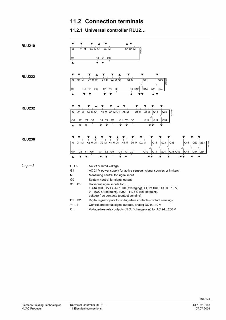
105/128
Siemens Building Technologies Universal Controller RLU2… CE1P3101en
HVAC Products 11 Electrical connections 07.07.2004
11.2 Connection terminals
11.2.1 Universal controller RLU2…
Y1 G0
G
G0
X1 M X2 M G1 X3 M D1 M
G1
3101G01
G1
Y1 G0
G
G0
X1 M X2 M G1 X3 M D1 M
G1
X4 M G1
Y2 G0G1 Q24
Q23
Q12 Q14
Q11
3101G02
N1 N2
Y1 G0
G
G0
X1 M X2 M G1 X3 M D1 M
G1
X4 M G1
Y2 G0G1 Q34
Q33
Q12 Q14
Q11
Y3 G0G1
D2 MX5 M
3101G03
Y1 G0
G
G0
X1 M X2 M G1 X3 M D1 M
G1
X4 M G1
Y2 G0G1 Q24
Q23
Q12 Q14
Q11
Y3 G0G1
D2 MX5 M
Q34
Q33
Q54
Q53
Q64
Q63
Q42 Q44
Q41
3101G04
G, G0 AC 24 V rated voltage
G1 AC 24 V power supply for active sensors, signal sources or limiters
M Measuring neutral for signal input
G0 System neutral for signal output
X1…X6 Universal signal inputs for
LG-Ni 1000, 2x LG-Ni 1000 (averaging), T1, Pt 1000, DC 0…10 V,
0…1000 Ω (setpoint), 1000…1175 Ω (rel. setpoint),
voltage-free contacts (contact sensing)
D1…D2 Digital signal inputs for voltage-free contacts (contact sensing)
Y1…3 Control and status signal outputs, analog DC 0…10 V
Q… Voltage-free relay outputs (N.O. / changeover) for AC 24…230 V
RLU210
RLU222
RLU232
RLU236
Legend
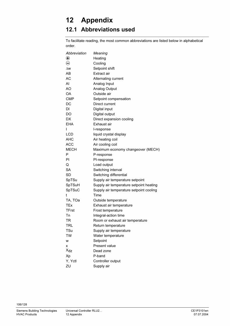
106/128
Siemens Building Technologies Universal Controller RLU2… CE1P3101en
HVAC Products 12 Appendix 07.07.2004
12 Appendix
12.1 Abbreviations used
To facilitate reading, the most common abbreviations are listed below in alphabetical
order.
Abbreviation Meaning
Heating
Cooling
∆w Setpoint shift
AB Extract air
AC Alternating current
AI Analog Input
AO Analog Output
OA Outside air
CMP Setpoint compensation
DC Direct current
DI Digital input
DO Digital output
DX Direct expansion cooling
EHA Exhaust air
I I-response
LCD liquid crystal display
AHC Air heating coil
ACC Air cooling coil
MECH Maximum economy changeover (MECH)
P P-response
PI PI-response
Q Load output
SA Switching interval
SD Switching differential
SpTSu Supply air temperature setpoint
SpTSuH Supply air temperature setpoint heating
SpTSuC Supply air temperature setpoint cooling
t Time
TA, TOa Outside temperature
TEx Exhaust air temperature
TFrst Frost temperature
Tn Integral-action time
TR Room or exhaust air temperature
TRL Return temperature
TSu Supply air temperature
TW Water temperature
w Setpoint
x Present value
Xdz Dead zone
Xp P-band
Y, Yctl Controller output
ZU Supply air

107/128
Siemens Building Technologies Universal Controller RLU2… CE1P3101en
HVAC Products 12 Appendix 07.07.2004
12.2 Synco 200 operating texts
Operating text Explanation
°C Degrees Celsius
F Degrees Fahrenheit
0.0 Universal 000.0
0000 Universal 0000
0-10 Active DC 0...10 V = 0...15 °C
2xNI 2xNi1000
3P 3-position
3-POINT 3-position output
A Basic type A room temp
ACCESS Access levels
ACK Fault acknowledgement
ACTING Control loop with risk of frost
ACTTIME Actuator run time
ADAP Plant type adapted
AO Modulating output
APPL ID Plant type
AUTO Auto
CAS/CON Casc/const changeover input
CASC Cascade
CH OVER 2-pipe heating/cooling system
CLOS Closing
CLSD Closed
CMF Comfort
CMP1D [Setp compensation 1] delta
CMP1END [Setp compensation 1] end
CMP1STT [Setp compensation 1] start
CMP2D [Setp compensation 2] delta
CMP2END [Setp compensation 2] end
CMP2STT [Setp compensation 2] start
CNST Constant
COMB Alternating
COMMIS Commissioning
CONFIG Extra configuration
COOL Cooling
COOLER Air cooling coil valve
CORR Correction
CTL1 Controller 1
CTL2 Controller 2
CTLOOP 1 Controller 1
CTLOOP 2 Controller 2
DIFF Differential input
DIG Frost protection unit Digital
DIG Digital
DLY OFF Switch-off delay
DV ALM Deviation signal
DMP Mixed air damper
DV DLYH Deviation signal delay top
DV DLYL Deviation signal delay bottom
ECO Economy
ERC Heat recovery equipment
EXP Password
FROST Actual value frost protection
FRST Frost protection
HEAT Heating
HREC Heat recovery output
HREC Mixing dampers/HR
IN X Preselection external

108/128
Siemens Building Technologies Universal Controller RLU2… CE1P3101en
HVAC Products 12 Appendix 07.07.2004
Synco 200 operating texts, continued
INVALID Caution!
INVERS Inversion
LABEL Input identifier
LIM General limit controller
LIM DHI Gen limiter differential high
LIM DLO Gen limiter differential low
LIM MAX Gen limiter limit value high
LIM MIN Gen limiter limit value low
LIM TN Gen limiter integr action time Tn
LIM X Actual value general limiter
LIM XP Gen limiter P-band Xp
LIMCOOL Reduction min limitation cooling
LOCK S1 [Sequence 1] outside temp >
LOCK S2 [Sequence 2] outside temp >
LOCK S4 [Sequence 4] outside temp <
LOCK S5 [Sequence 5] outside temp <
MAIN Main controlled variable
MAINALM Main contr var sensor error
MAX Limitation max
MAX Maximum
MAX POS Positioning signal max
MAX VAL Value high
MECH 1 MECH input 1
MECH 2 MECH input 2
MECHSET MECH limit value
MIN Limitation min
MIN Minimum
MIN POS Positioning signal min
MIN VAL Value low
MODE Operating mode
NI Passive Ni1000
NO No
NO None
NORMPOS Normal position
OFF Off
OFF TN Plant OFF Tn
OFF XP P-band Xp
OFFTIME Locking time
OFF-Y Load-dependent OFF
OHM Ohm
OK OK
ON On
ON DLY Startup delay
ON-OUTS Outside temp-dependent ON
ON-Y Load-dependent ON
OPEN Opening
OPEN Open
OPMODE Preselected optg mode input
ORIG Plant type original (not adapted)
OUTS Outside temperature
OUTSIDE Actual value outside temp
PASSWRD Password
PCF Precomfort
PRIO CH Run priority changeover
PRT Protection
PT Pt1000
PU1 Pump 1
PU2 Pump 2
PU3 Pump 3
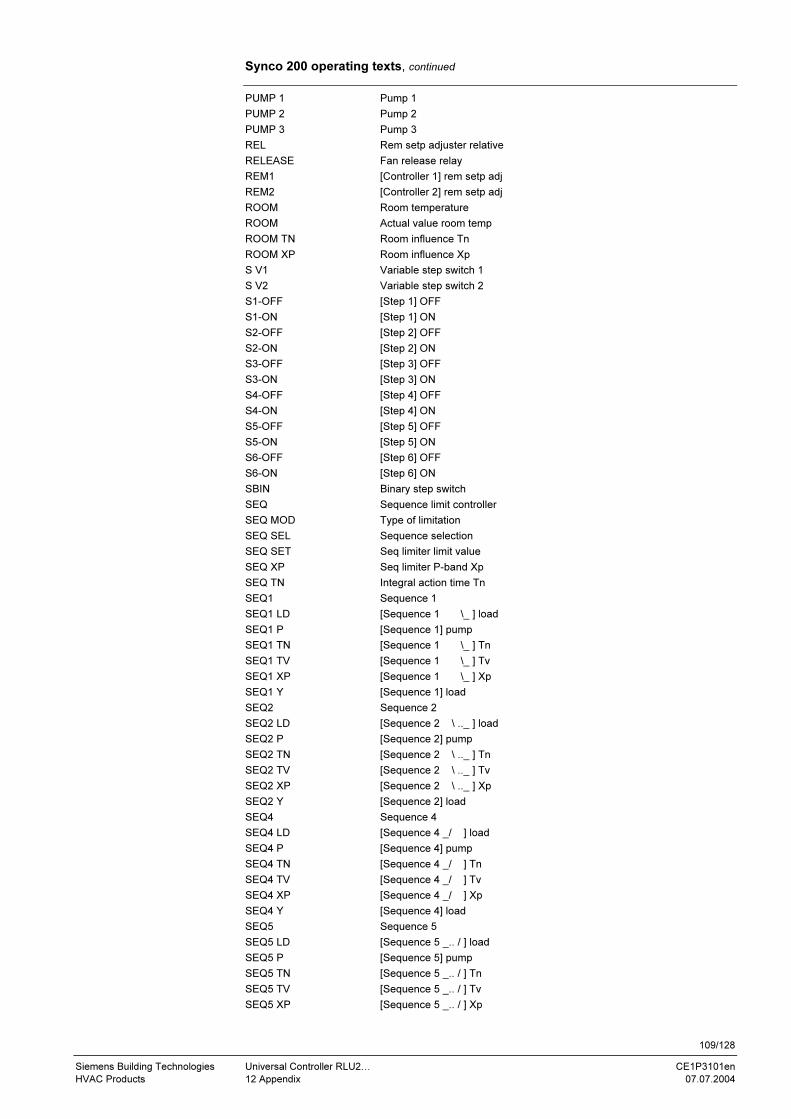
109/128
Siemens Building Technologies Universal Controller RLU2… CE1P3101en
HVAC Products 12 Appendix 07.07.2004
Synco 200 operating texts, continued
PUMP 1 Pump 1
PUMP 2 Pump 2
PUMP 3 Pump 3
REL Rem setp adjuster relative
RELEASE Fan release relay
REM1 [Controller 1] rem setp adj
REM2 [Controller 2] rem setp adj
ROOM Room temperature
ROOM Actual value room temp
ROOM TN Room influence Tn
ROOM XP Room influence Xp
S V1 Variable step switch 1
S V2 Variable step switch 2
S1-OFF [Step 1] OFF
S1-ON [Step 1] ON
S2-OFF [Step 2] OFF
S2-ON [Step 2] ON
S3-OFF [Step 3] OFF
S3-ON [Step 3] ON
S4-OFF [Step 4] OFF
S4-ON [Step 4] ON
S5-OFF [Step 5] OFF
S5-ON [Step 5] ON
S6-OFF [Step 6] OFF
S6-ON [Step 6] ON
SBIN Binary step switch
SEQ Sequence limit controller
SEQ MOD Type of limitation
SEQ SEL Sequence selection
SEQ SET Seq limiter limit value
SEQ XP Seq limiter P-band Xp
SEQ TN Integral action time Tn
SEQ1 Sequence 1
SEQ1 LD [Sequence 1 \_ ] load
SEQ1 P [Sequence 1] pump
SEQ1 TN [Sequence 1 \_ ] Tn
SEQ1 TV [Sequence 1 \_ ] Tv
SEQ1 XP [Sequence 1 \_ ] Xp
SEQ1 Y [Sequence 1] load
SEQ2 Sequence 2
SEQ2 LD [Sequence 2 \ .._ ] load
SEQ2 P [Sequence 2] pump
SEQ2 TN [Sequence 2 \ .._ ] Tn
SEQ2 TV [Sequence 2 \ .._ ] Tv
SEQ2 XP [Sequence 2 \ .._ ] Xp
SEQ2 Y [Sequence 2] load
SEQ4 Sequence 4
SEQ4 LD [Sequence 4 _/ ] load
SEQ4 P [Sequence 4] pump
SEQ4 TN [Sequence 4 _/ ] Tn
SEQ4 TV [Sequence 4 _/ ] Tv
SEQ4 XP [Sequence 4 _/ ] Xp
SEQ4 Y [Sequence 4] load
SEQ5 Sequence 5
SEQ5 LD [Sequence 5 _.. / ] load
SEQ5 P [Sequence 5] pump
SEQ5 TN [Sequence 5 _.. / ] Tn
SEQ5 TV [Sequence 5 _.. / ] Tv
SEQ5 XP [Sequence 5 _.. / ] Xp

110/128
Siemens Building Technologies Universal Controller RLU2… CE1P3101en
HVAC Products 12 Appendix 07.07.2004
Synco 200 operating texts, continued
SEQ5 Y [Sequence 5] load
SERV Service level
SET MAX Comfort setpoint high
SET MAX Economy setpoint high
SET MIN Comfort setpoint low
SET MIN Economy setpoint low
SETCOOL Comfort cooling setpoint
SETCOOL Economy cooling setpoint
SETHEAT Comfort heating setpoint
SETHEAT Economy heating setpoint
SET-OFF Plant OFF frost protection setp
SET-ON Risk of frost limit
SETPOINT Setpoints
SETTING Settings
SHIFT Universal shift
SIGNALY Measured value signal output
SLIN Linear step switch
START OK Caution! Plant starts
STATUS Device state
STEP 1 Step 1
STEP 2 Step 2
STEP 3 Step 3
STEP 4 Step 4
STEP 5 Step 5
STEP 6 Step 6
STEP V1 Variable step switch 1
STEP V2 Variable step switch 2
STEPBIN Binary step switch
STEPLIN Linear step switch
STOP OK Caution! Plant stops
SU DMAX Max limitation supply air delta
SU DMIN Min limitation supply air delta
SU MAX Supply air limit value max
SU MIN Supply air limit value min
SUM-D Summer compensation delta
SUM-END Summer compensation end
SUM-STT Summer compensation start
SUPPLY Supply air temperature
SW-VERS Software version
TIMEOUT Control timeout
TOOLING Operation locked
TYPE Type
TYPE Identification
U Basic type U univ controller
UNIT Unit
USER User level
VALUES Inputs / outputs
WIN-D Winter compensation delta
WIN-END Winter compensation end
WIN-STT Winter compensation start
WIRING TEST Wiring test
XP P-band Xp
YES Yes
YES Acknowledgement manual
YES3 Acknowledgement autom 3x

111/128
Siemens Building Technologies Universal Controller RLU2… CE1P3101en
HVAC Products 12 Appendix 07.07.2004
12.3 Configuration
12.3.1 Explanation of the configuration principle
The controller includes a large number of pre-configured function blocks. The function
blocks available for the various RLU2… universal controllers are shown the respective
configuration diagrams. They include:
• Input identifiers (inputs, input functions)
• Function blocks for open and closed-loop control functions
• Aggregates (outputs, output functions)
Project engineers can add connections from the individual input and output functions
(i.e. their internal signals) to the assigned terminals.
Physical inputs:
• D digital
• X universal
Physical outputs:
• Q relay
• Y DC 0…10 V
Be careful to observe the following rules and properties when using the inputs:
• The input identifier can be a device or a special sensor:
OUTS (outside temperature), ROOM (room temperature), FRST (frost protection),
REMx (setpoint adjuster)
• Multiple use of input signals is possible without limitation (e.g. room temperature
signal as the main controlled variable and as the maximum economy changeover
criterion for the damper)
• When an input is connected, the controller presents only the possible unit on the
display.
• Input alarming is only enabled if the input is connected before completion of
commissioning.
• If you change an input identifier (LABEL) all of the settings associated with it also
change (e.g. Xp used to be 28 K, and now it is 10 Pa).
Sequence:
• First the basic configuration (APPL ID), then the extra configuration (CONFIG)
• First the input identifiers (LABEL), then the control functions, and then the
aggregates.
Wiring choices:
• Always from the arrow to the line
• From the function to the input: "x" to "x"
• From the output block to the output terminal: Analog "Y" to "Y"
• Relay "Q" to "Q"
• From the controller: load "y" to "y", pumps "p" to "p"
Be careful to observe the following when using the outputs:
• Connect the output functions to the correct terminals. Each output terminal can only
be used once (e.g. Q1 for Pump 1)
• Each output function has no more than 2 load signal inputs with maximum selection.
Example: The air cooler valve opens if the room temperature or room air humidity is
too high.
Configuration diagrams,
contents
Configuration diagrams,
use
Identifiers used
Use of Xx inputs
Configuration
procedures
Use of Yx outputs
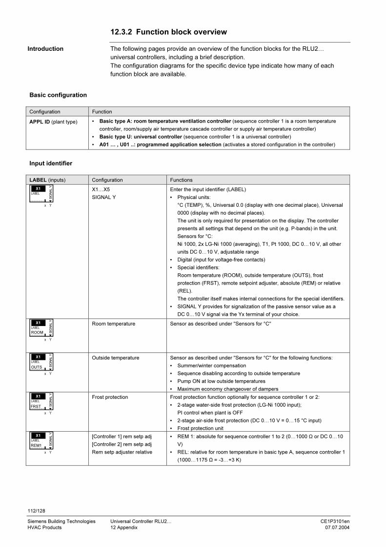
112/128
Siemens Building Technologies Universal Controller RLU2… CE1P3101en
HVAC Products 12 Appendix 07.07.2004
12.3.2 Function block overview
The following pages provide an overview of the function blocks for the RLU2…
universal controllers, including a brief description.
The configuration diagrams for the specific device type indicate how many of each
function block are available.
Basic configuration
Configuration Function
APPL ID (plant type) • Basic type A: room temperature ventilation controller (sequence controller 1 is a room temperature
controller, room/supply air temperature cascade controller or supply air temperature controller)
• Basic type U: universal controller (sequence controller 1 is a universal controller)
• A01 … , U01 ..: programmed application selection (activates a stored configuration in the controller)
Input identifier
LABEL (inputs) Configuration Functions
X1…X5
SIGNAL Y
Enter the input identifier (LABEL)
• Physical units:
°C (TEMP), %, Universal 0.0 (display with one decimal place), Universal
0000 (display with no decimal places).
The unit is only required for presentation on the display. The controller
presents all settings that depend on the unit (e.g. P-bands) in the unit.
Sensors for °C:
Ni 1000, 2x LG-Ni 1000 (averaging), T1, Pt 1000, DC 0…10 V, all other
units DC 0…10 V, adjustable range
• Digital (input for voltage-free contacts)
• Special identifiers:
Room temperature (ROOM), outside temperature (OUTS), frost
protection (FRST), remote setpoint adjuster, absolute (REM) or relative
(REL).
The controller itself makes internal connections for the special identifiers.
• SIGNAL Y provides for signalization of the passive sensor value as a
DC 0…10 V signal via the Yx terminal of your choice.
Room temperature Sensor as described under "Sensors for °C"
Outside temperature Sensor as described under "Sensors for °C" for the following functions:
• Summer/winter compensation
• Sequence disabling according to outside temperature
• Pump ON at low outside temperatures
• Maximum economy changeover of dampers
Frost protection Frost protection function optionally for sequence controller 1 or 2:
• 2-stage water-side frost protection (LG-Ni 1000 input);
PI control when plant is OFF
• 2-stage air-side frost protection (DC 0…10 V = 0…15 °C input)
• Frost protection unit
[Controller 1] rem setp adj
[Controller 2] rem setp adj
Rem setp adjuster relative
• REM 1: absolute for sequence controller 1 to 2 (0…1000 Ω or DC 0…10
V)
• REL: relative for room temperature in basic type A, sequence controller 1
(1000…1175 Ω = -3…+3 K)
Introduction
X1
x Y
SIG
NA
L Y
LABEL
X1
x Y
SIG
NA
L Y
LABEL
ROOM
X1
x Y
SIG
NA
L Y
LABEL
OUTS
X1
x Y
SIG
NA
L Y
LABEL
FRST
X1
x Y
SIG
NA
L Y
LABEL
REM1

113/128
Siemens Building Technologies Universal Controller RLU2… CE1P3101en
HVAC Products 12 Appendix 07.07.2004
Open and closed-loop control functions
CTLOOP x (controller) Configuration Functions
Controller 1, basic type A
• Supply air temp. (SUPPLY)
• Gen limit controller (LIM)
• Seq limit controller (SEQ)
• Casc./const-changeover input
(CAS/CON)
• Sequence S1…S5 load (y)
• Sequence S1…S5 pump (p)
• Deviation message output
(DV ALM)
Sequence controller, usable as a P, PI or PID controller.
If supply air temp. (casc.) configured, usable as:
• Room/supply air cascade ctrlr with supply air high/low limit control
• Supply air temperature controller
• Room temperature controller (supply air configured but not
connected)
If supply air temp. (casc.) not configured, usable as:
• Room temperature present value controller
Controller features:
• Configurable sequence assignments; a load output (modulating
output AO1…3, heat recovery unit, mixing damper, var. step switch
1…2), linear step switch, binary step switch and a pump can be
connected to each sequence.
• Heating sequences S1 and S2 (\\_)
• Cooling sequences S4 and S5, (_//)
• Gen limit controller acts on all sequences
• Seq limit controller, definable as low or high limit controller, acts on
one selectable sequence (in close direction)
• Summer/winter compensation with outside temperature
• Sequence lock acc to OT
• Alarm for unacceptable control deviation can be activated
Controller 1, basic type U;
Controller 2, (basic types A and U):
• Main controlled variable
• Differential input (DIFF)
• Universal shift SHIFT ( )
• Gen limit controller (LIM)
• Seq limit controller (SEQ)
• Sequence S1…S5 load (y)
• Sequence S1…S5 pump (p)
• Deviation alarm output (DVALM)
Universally usable sequence controller, as a P, PI or PID controller.
• Configurable sequence assignments; a load output (modulating
output, var. step switch 1…5), linear step switch, binary step switch
and a pump can be connected to each sequence.
• Heating sequences S1 and S2 (\\_)
• Cooling sequences S4 and S5 (_//)
• Simple controller or differential controller
(setpoint linkable to sequence controller 1)
• Gen limit controller acts on all sequences
• Seq limit controller, definable as low or high limit controller, acts on
one selectable sequence (in close direction)
• Universal shift
• Sequence lock acc to OT
• Alarm for unacceptable control deviation can be activated
MODE (Operating
mode)
Configuration Functions
Basic types A and U:
• Operating mode input
(OPMODE)
• Heating/cooling changeover
input (CH OVER)
• Fan enable relay output
(RELEASE)
Room operating modes.
• Operating mode input (OPMODE) for changeover between comfort
and economy setpoints (RLU210 and RLU222 only)
• Heating cooling changeover input (CH OVER) for "2-pipe
heating/cooling system (only RLU210 basic type and all basic type
U controllers)
• Fan enable relay output (RELEASE): output for disabling the fan in
case of frost and external alarms.
FROST (frost protection Configuration Functions
• 2-stage air-side frost protection (DC 0…10 V = 0…15 °C input)
• Frost protection unit
y p y p y p y p
x xx x
Q
LIM SEQ CAS/CON
1CTLOOP 1
SE
Q2 Y
SE
Q2 P
SE
Q1 Y
SE
Q1 P
SE
Q4 Y
SE
Q4 P
SE
Q5 Y
SE
Q5 P
DV
ALM
SUPPLY
y p y p y p y p
x x xx
DIFF
x
Q
MAIN
LIM SEQ SHIFT
1CTLOOP 1
DV
ALM
SE
Q2 Y
SE
Q2 P
SE
Q1 Y
SE
Q1 P
SE
Q4 Y
SE
Q4 P
SE
Q5 Y
SE
Q5 P
D1
x
MODE
Q
CH
OV
ER
x
OP
MO
DE
RELEASE
FROST
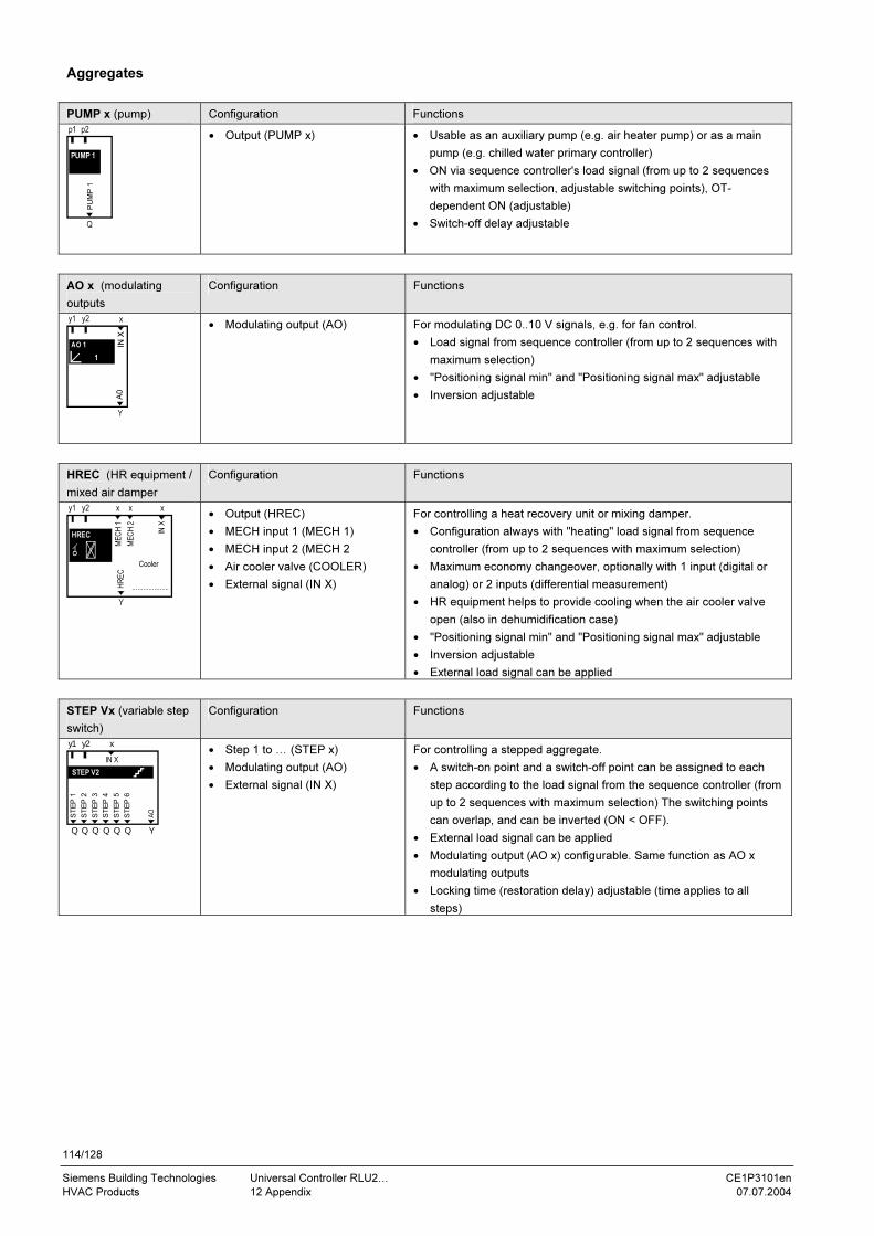
114/128
Siemens Building Technologies Universal Controller RLU2… CE1P3101en
HVAC Products 12 Appendix 07.07.2004
Aggregates
PUMP x (pump) Configuration Functions
• Output (PUMP x)
• Usable as an auxiliary pump (e.g. air heater pump) or as a main
pump (e.g. chilled water primary controller)
• ON via sequence controller's load signal (from up to 2 sequences
with maximum selection, adjustable switching points), OT-
dependent ON (adjustable)
• Switch-off delay adjustable
AO x (modulating
outputs
Configuration Functions
• Modulating output (AO) For modulating DC 0..10 V signals, e.g. for fan control.
• Load signal from sequence controller (from up to 2 sequences with
maximum selection)
• "Positioning signal min" and "Positioning signal max" adjustable
• Inversion adjustable
HREC (HR equipment /
mixed air damper
Configuration Functions
• Output (HREC)
• MECH input 1 (MECH 1)
• MECH input 2 (MECH 2
• Air cooler valve (COOLER)
• External signal (IN X)
For controlling a heat recovery unit or mixing damper.
• Configuration always with "heating" load signal from sequence
controller (from up to 2 sequences with maximum selection)
• Maximum economy changeover, optionally with 1 input (digital or
analog) or 2 inputs (differential measurement)
• HR equipment helps to provide cooling when the air cooler valve
open (also in dehumidification case)
• "Positioning signal min" and "Positioning signal max" adjustable
• Inversion adjustable
• External load signal can be applied
STEP Vx (variable step
switch)
Configuration Functions
• Step 1 to … (STEP x)
• Modulating output (AO)
• External signal (IN X)
For controlling a stepped aggregate.
• A switch-on point and a switch-off point can be assigned to each
step according to the load signal from the sequence controller (from
up to 2 sequences with maximum selection) The switching points
can overlap, and can be inverted (ON < OFF).
• External load signal can be applied
• Modulating output (AO x) configurable. Same function as AO x
modulating outputs
• Locking time (restoration delay) adjustable (time applies to all
steps)
p1 p2
Q
PU
MP
1
PUMP 1
1
y1 y2
IN X
Y
x
A0
AO 1
Y
y1 y2 x x
....................
x
IN X
Cooler
HREC
ME
CH
1
ME
CH
2
HR
EC
Var. Stufensch. 2
y1 y2 x
Q Q Q Q Q Q Y
IN X
ST
EP
1
ST
EP
2
ST
EP
3
ST
EP
4
ST
EP
5
ST
EP
6
AO
STEP V2
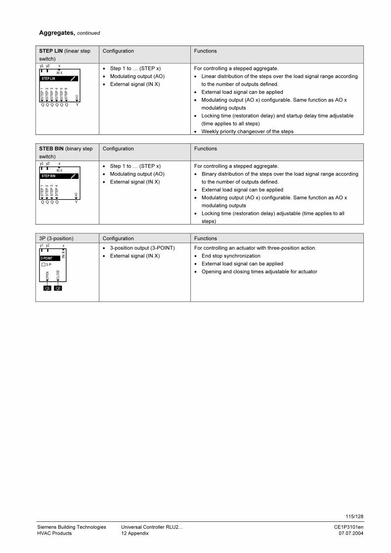
115/128
Siemens Building Technologies Universal Controller RLU2… CE1P3101en
HVAC Products 12 Appendix 07.07.2004
Aggregates, continued
STEP LIN (linear step
switch)
Configuration Functions
• Step 1 to … (STEP x)
• Modulating output (AO)
• External signal (IN X)
For controlling a stepped aggregate.
• Linear distribution of the steps over the load signal range according
to the number of outputs defined.
• External load signal can be applied
• Modulating output (AO x) configurable. Same function as AO x
modulating outputs
• Locking time (restoration delay) and startup delay time adjustable
(time applies to all steps)
• Weekly priority changeover of the steps
STEB BIN (binary step
switch)
Configuration Functions
• Step 1 to … (STEP x)
• Modulating output (AO)
• External signal (IN X)
For controlling a stepped aggregate.
• Binary distribution of the steps over the load signal range according
to the number of outputs defined.
• External load signal can be applied
• Modulating output (AO x) configurable. Same function as AO x
modulating outputs
• Locking time (restoration delay) adjustable (time applies to all
steps)
3P (3-position) Configuration Functions
• 3-position output (3-POINT)
• External signal (IN X)
For controlling an actuator with three-position action.
• End stop synchronization
• External load signal can be applied
• Opening and closing times adjustable for actuator
y1 y2 x
Q Q Q Q Q Q Y
IN X
ST
EP
2
ST
EP
3
ST
EP
4
ST
EP
5
ST
EP
6
AO
ST
EP
1
STEP LIN
y1 y2 x
Q Q Q Q Y
IN X
ST
EP
2
ST
EP
3
ST
EP
4
ST
EP
1
AO
STEP BIN
y1 y2
IN X
x
3 P
Q1 Q2
OPEN
CLOSE
3 POINT
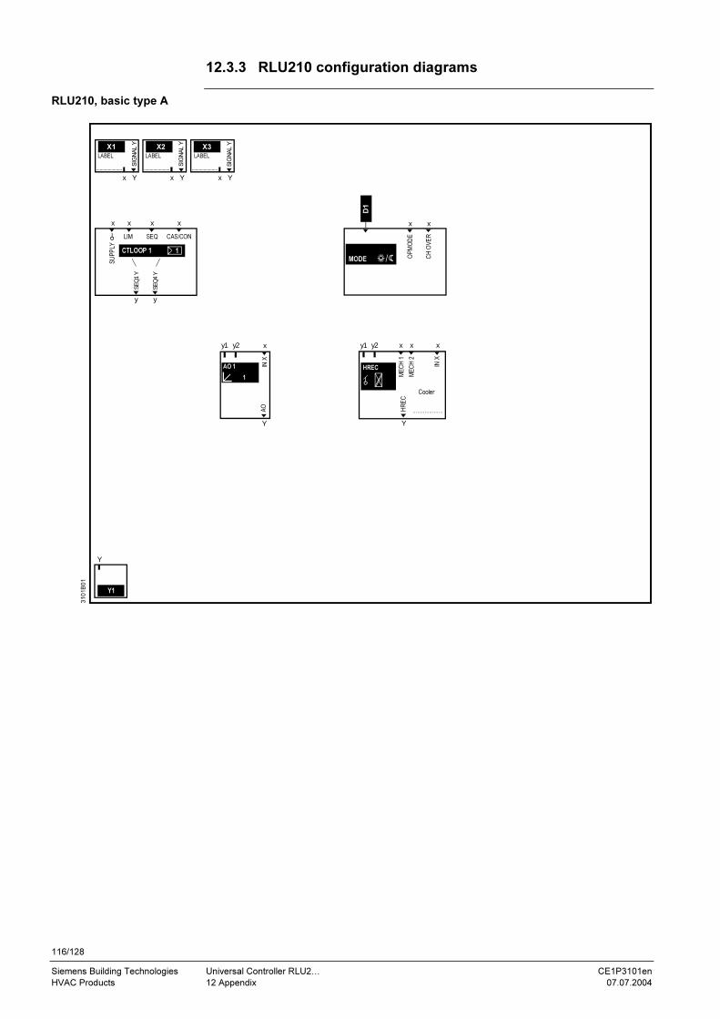
116/128
Siemens Building Technologies Universal Controller RLU2… CE1P3101en
HVAC Products 12 Appendix 07.07.2004
12.3.3 RLU210 configuration diagrams
X1
1
Y1
x
y y
x xx
y1 y2
Y
310
1B
01
X2
xY Y
X3
x Y
SU
PP
LY
x
IN X
Y
x
AO
LABEL
SIG
NA
L Y
SIG
NA
L Y
SIG
NA
L Y
LABEL
LIM SEQ CAS/CON
SE
Q1 Y
SE
Q4 Y
D1
x
OP
MO
DE
LABEL
1CTLOOP 1
MODE CH
OV
ER
x
AO 1
Y
y1 y2 x x
....................
x
IN X
Cooler
HREC
ME
CH
1
ME
CH
2
HR
EC
RLU210, basic type A

117/128
Siemens Building Technologies Universal Controller RLU2… CE1P3101en
HVAC Products 12 Appendix 07.07.2004
X1
1
Y1
x
y1 y2
Y
310
1B
02
X2
xY Y
X3
x Y
IN X
Y
x
A0
LABEL
SIG
NA
L Y
SIG
NA
L Y
SIG
NA
L Y
LABEL
D1
x
y y
x x xx
DIF
F
x
MA
IN
LIM SEQSHIFT
LABEL
CTLOOP 1
AO 1
SE
Q1 Y
SE
Q4 Y
CH
OV
ER
OP
MO
DE
MODE
Y
y1 y2 x x
....................
x
IN X
Cooler
HREC
ME
CH
1
ME
CH
2
HR
EC
x
RLU210, basic type U
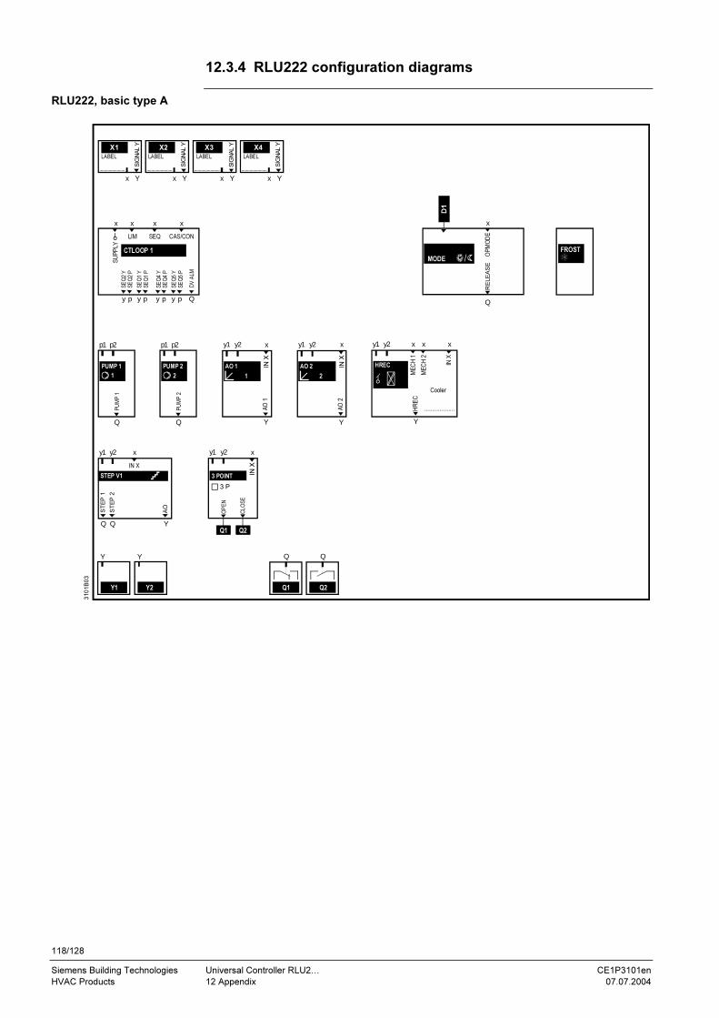
118/128
Siemens Building Technologies Universal Controller RLU2… CE1P3101en
HVAC Products 12 Appendix 07.07.2004
12.3.4 RLU222 configuration diagrams
RLU222, basic type A
X1
SE
Q2 Y
1
Y1 Y2
x
y p y p y p y p
x xx
y1 y2
YQ Q
xy2y1
p1 p2
Q
p2p1
Y Y
Q1
Q
310
1B
03
X2
xY Y
X3
x
X4
xY Y
x
Q
IN X
Y
2
y1 y2x x
Y
y1 y2 x x
ME
CH
1H
RE
C
....................
x
AO
1
IN X
IN X
IN X
LABEL
SIG
NA
L Y
SIG
NA
L Y
SIG
NA
L Y
SIG
NA
L Y
LABEL LABEL
LIM SEQ CAS/CON
SE
Q2 P
SE
Q1 Y
SE
Q1 P
SE
Q4 Y
SE
Q4 P
SE
Q5 Y
SE
Q5 P
DV
ALM
PU
MP
1
Q
PU
MP
2
Y
AO
2
Cooler
ST
EP
1
AO
ST
EP
2
D1
y1 y2
IN X
x
Q2
Q
x
LABEL
MODE
21
OP
MO
DE
Q1 Q2
OP
EN
CL
OS
E
3 PR
ELE
AS
E
Q
CTLOOP 1 FROST
PUMP 1 PUMP 2 AO 1 AO 2 HREC
ME
CH
2
STEP V1 3 POINT
SU
PP
LY

119/128
Siemens Building Technologies Universal Controller RLU2… CE1P3101en
HVAC Products 12 Appendix 07.07.2004
X1
1
Y1 Y2
x
y1 y2
YQ Q
xy2y1
p1 p2
Q
p2p1
Y Y
Q1
Q
310
1B
04
X2
xY Y
X3
x
X4
xY Y
IN X
Y
2
y1 y2x x
Y
y1 y2 x x
....................
x
A0
IN X
IN X
IN X
LABEL
SIG
NA
L Y
SIG
NA
L Y
SIG
NA
L Y
SIG
NA
L Y
LABEL LABEL
PU
MP
1
Q
PU
MP
2
Y
A0
Cooler
ST
EP
1
ST
EP
2
FROST
D1
Q2
Q
x
LABEL
y p y p y p y p
x x xx
DIF
F
x
Q
MA
IN
LIM SEQ SHIFT
1
MODE
y1 y2
IN X
x
3 P
Q1 Q2
OP
EN
CL
OS
EQ
CH
OV
ER
x
OP
MO
DE
SE
Q2 Y
SE
Q2 P
SE
Q1 Y
SE
Q1 P
SE
Q4 Y
SE
Q4 P
SE
Q5 Y
SE
Q5 P
DV
ALM
CTLOOP 1
RE
LE
AS
E
PUMP 1 PUMP 2 AO 1 AO 2 HREC
ME
CH
1
ME
CH
2
HR
EC
A0
STEP V1 3 POINT
RLU222, basic type U

120/128
Siemens Building Technologies Universal Controller RLU2… CE1P3101en
HVAC Products 12 Appendix 07.07.2004
12.3.5 RLU232 configuration diagrams
X1
1
Y1 Y2 Y3
x
y p y p y p y p
x x x xx x x
y p y p
y1 y2
YQ Q
xy2y1
p1 p2
Q
p2p1
Y Y Y
DIF
F
Q1
Q
Q3
Q
x
310
1B
05
X2
xY Y
X3
x
X4
xY Y
X5
x Y
MA
IN
x
Q
IN X
Y
2
y1 y2
3
y1 y2
Y
x x x
Y
y1 y2 x x
ME
CH
1
HR
EC
x
A0
A0
IN X
IN X
IN X
y1 y2 x
Q Q Y
IN X
y1 y2 x
Q Q Y
IN XIN X
LABEL
SIG
NA
L Y
SIG
NA
L Y
SIG
NA
L Y
SIG
NA
L Y
SIG
NA
L Y
LABEL LABEL LABEL
LIM SEQ CAS/CON LIM SEQ SHIFT
PU
MP
1
Q
PU
MP
2
Y
A0
Cooler
AO
ST
EP
2
ST
EP
1
ST
EP
2
ST
EP
1
FROST
D1
D2
1 2
3
PUMP 1
Pumpe
1 2MODE
LABEL
Q
CTLOOP 1 CTLOOP 2
SE
Q2 Y
SE
Q2 P
SE
Q1 Y
SE
Q1 P
SE
Q4 Y
SE
Q4 P
SE
Q5 Y
SE
Q5 P
DV
ALM
SE
Q1 Y
SE
Q1 P
SE
Q4 Y
SE
Q4 P
PUMP 2
ST
EP
1
ST
EP
2
A0
STEP LIN
A0
STEP V1
ME
CH
2
....................
SU
PP
LY
RLU232, basic type A
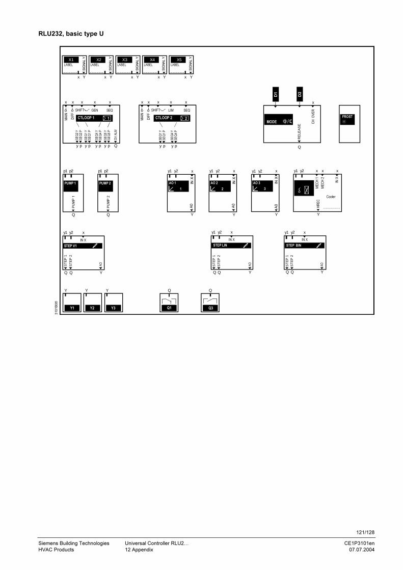
121/128
Siemens Building Technologies Universal Controller RLU2… CE1P3101en
HVAC Products 12 Appendix 07.07.2004
310
1B
06
3
Y
x
Y
y1 y2 x x
ME
CH
1
HR
EC
....................
x
A0
IN
X
IN X
y1 y2 x
Q Q Y
IN X
Cooler
ST
EP
2
ST
EP
1
AO
X1
Y1 Y2 Y3 Q1 Q3
X2 X3 X4 X5
SIG
NA
L Y
SIG
NA
L Y
SIG
NA
L Y
SIG
NA
L Y
SIG
NA
L Y
FROST
D1
D2
MODE
Q
CH
O
VE
R
x
ME
CH
2
STEP BIN
RE
LE
AS
E
y p y p y p y p
x x x x xx x x
y p y pD
IFF
x
MA
IN
DIF
F
x
Q
LIM SEQ
MA
IN
SHIFTGEN SEQ SHIFT
1 2CTLOOP 1 CTLOOP 2
SE
Q2 Y
SE
Q2 P
SE
Q1 Y
SE
Q1 P
SE
Q4 Y
SE
Q4 P
SE
Q5 Y
SE
Q5 P
DV
ALM
SE
Q1 Y
SE
Q1 P
SE
Q4 Y
SE
Q4 P
1
y1 y2p1 p2
Q
p2p1
IN X
Y
2
y1 y2 y1 y2x x
A0
IN X
PU
MP
1
Q
PU
MP
2
Y
A0
AO 2AO 1PUMP 1 PUMP 2 AO 3
YQ Q
xy2y1 y1 y2 x
Q Q Y
IN XIN X
ST
EP
1
AO
ST
EP
2
ST
EP
2
AO
ST
EP
1
Y Y Y Q Q
STEP LINSTEP V1
x xY Y x xY Y x Y
LABEL LABEL LABEL LABELLABEL
RLU232, basic type U
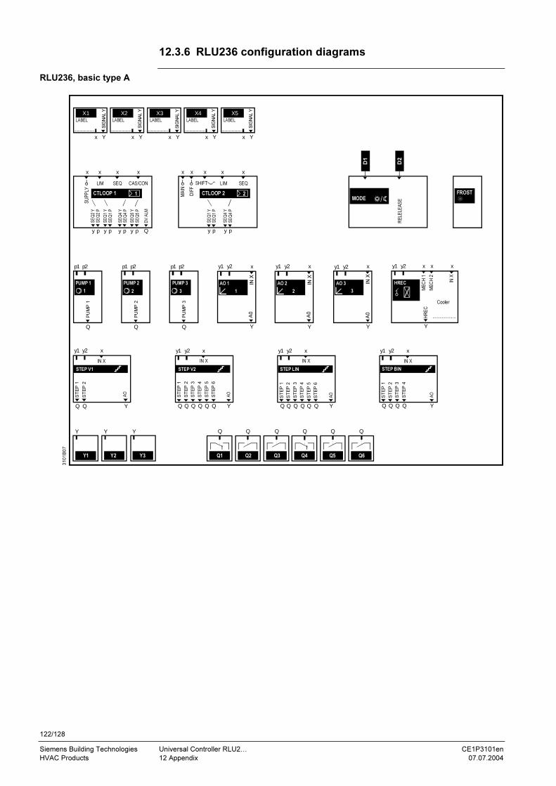
122/128
Siemens Building Technologies Universal Controller RLU2… CE1P3101en
HVAC Products 12 Appendix 07.07.2004
12.3.6 RLU236 configuration diagrams
X1
1
Y1 Y2 Y3
x
y p y p y p y p
x x x xx x x
y p y p
y1 y2
YQ Q
xy2y1
p1 p2
Q
p2p1 p2p1
Y Y Y
DIF
F
Q1
Q
Q2
Q
Q3 Q4 Q5 Q6
QQQ Q
x
310
1B
07
X2
xY Y
X3
x
X4
xY Y
X5
x Y
MA
IN
x
Q
IN X
Y
2
y1 y2
3
y1 y2
Y
x x x
Y
y1 y2 x x
HR
EC
....................
x
A0
A0
IN X
IN X
IN X
y1 y2 x
Q Q Q Q Q Q Y
IN X
y1 y2 x
Q Q Q Q Q Q Y
IN X
y1 y2 x
Q Q Q Q Y
IN XIN X
LABEL
SIG
NA
L Y
SIG
NA
L Y
SIG
NA
L Y
SIG
NA
L Y
SIG
NA
L Y
LABEL LABEL LABEL
LIM SEQ CAS/CON LIM SEQ
DV
ALM
SHIFT
PU
MP
1
Q
PU
MP
2
Q
PU
MP
3
Y
A0
Cooler
ST
EP
1
AO
ST
EP
2
ST
EP
1
ST
EP
2
ST
EP
3
ST
EP
4
ST
EP
5
ST
EP
6
AO
ST
EP
2
ST
EP
3
ST
EP
4
ST
EP
5
ST
EP
6
AO
ST
EP
1
ST
EP
2
ST
EP
3
ST
EP
4
ST
EP
1
AO
FROST
D1
D2
LABEL
1MODE
2
1 2 3
PUMP 1 PUMP 2 PUMP 3 AO 1 AO 2 AO 3 HREC
ME
CH
1
ME
CH
2
STEP BIN STEP LIN STEP V2 STEP V1
CTLOOP 1 CTLOOP 2
SE
Q2 Y
SE
Q2 P
SE
Q1 Y
SE
Q1 P
SE
Q4 Y
SE
Q4 P
SE
Q5 Y
SE
Q5 P
SE
Q1 Y
SE
Q1 P
SE
Q4 Y
SE
Q4 P
RE
LE
LE
AS
E
SU
PP
LY
RLU236, basic type A
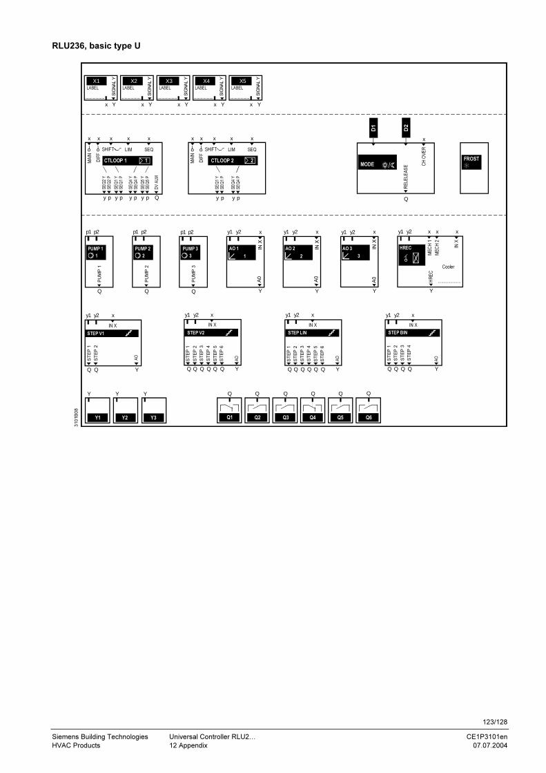
123/128
Siemens Building Technologies Universal Controller RLU2… CE1P3101en
HVAC Products 12 Appendix 07.07.2004
1
y p y p y p y p
x x x x xx x x
y p y p
y1 y2
YQ Q
xy2y1
p1 p2
Q
p2p1
DIF
F
x
310
1B
08
MA
IN
DIF
F
x
Q
IN X
Y
2
y1 y2
3
y1 y2
Y
x x x
Y
y1 y2 x x
....................
x
A0
A0
IN X
IN X
IN X
y1 y2 x
Q Q Q Q Q Q Y
IN X
y1 y2 x
Q Q Q Q Y
IN XIN X
LIM SEQ
MA
IN
SHIFT
PU
MP
1
Q
PU
MP
2
Y
A0
Cooler
ST
EP
1
AO
ST
EP
2
ST
EP
2
ST
EP
3
ST
EP
4
ST
EP
5
ST
EP
6
AO
ST
EP
1
ST
EP
2
ST
EP
3
ST
EP
4
ST
EP
1
AO
LIM SEQ SHIFT
X1
Y1 Y2 Y3
x
Y Y Y
X2
xY Y
X3
x
X4
xY Y
X5
x Y
LABEL
SIG
NA
L Y
SIG
NA
L Y
SIG
NA
L Y
SIG
NA
L Y
SIG
NA
L Y
LABEL LABEL LABEL
D1
D2
LABEL
Var. Stufensch. 2
y1 y2 x
Q Q Q Q Q Q Y
IN X
ST
EP
1
ST
EP
2
ST
EP
3
ST
EP
4
ST
EP
5
ST
EP
6
AO
Q1
Q
Q2
Q
Q3 Q4 Q5 Q6
QQQ Q
p2p1
Q
PU
MP
3
1 2MODE
1 2 3
Q
CH
OV
ER
x
FROSTCTLOOP 1D
V A
LM
SE
Q2 Y
SE
Q2 P
SE
Q1 Y
SE
Q1 P
SE
Q4 Y
SE
Q4 P
SE
Q5 Y
SE
Q5 P
CTLOOP 2
SE
Q1 Y
SE
Q1 P
SE
Q4 Y
SE
Q4 P
RE
LE
LE
AS
E
HREC
ME
CH
1
ME
CH
2
HR
EC
PUMP 1 PUMP 2 PUMP 3 AO 3AO 2AO 1
STEP BIN STEP LIN STEP V2 STEP V1
RLU236, basic type U
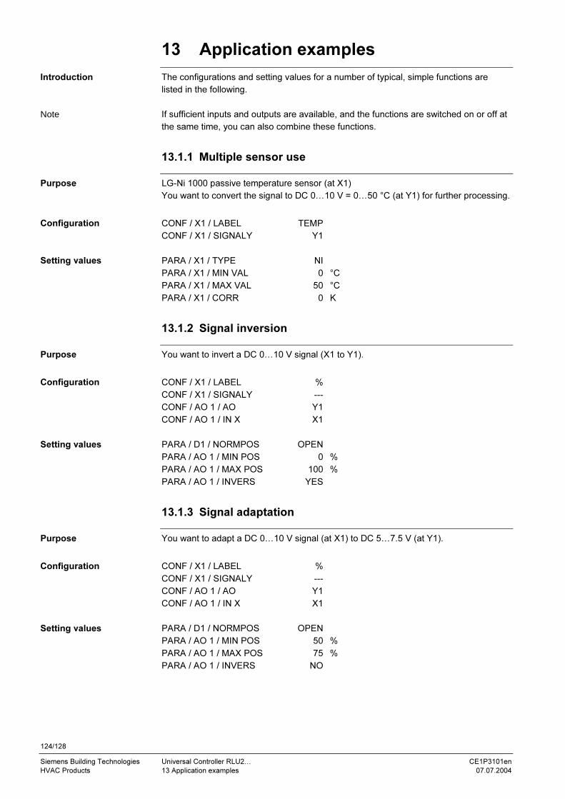
124/128
Siemens Building Technologies Universal Controller RLU2… CE1P3101en
HVAC Products 13 Application examples 07.07.2004
13 Application examples
The configurations and setting values for a number of typical, simple functions are
listed in the following.
If sufficient inputs and outputs are available, and the functions are switched on or off at
the same time, you can also combine these functions.
13.1.1 Multiple sensor use
LG-Ni 1000 passive temperature sensor (at X1)
You want to convert the signal to DC 0…10 V = 0…50 °C (at Y1) for further processing.
CONF / X1 / LABEL TEMP
CONF / X1 / SIGNALY Y1
PARA / X1 / TYPE NI
PARA / X1 / MIN VAL 0 °C
PARA / X1 / MAX VAL 50 °C
PARA / X1 / CORR 0 K
13.1.2 Signal inversion
You want to invert a DC 0…10 V signal (X1 to Y1).
CONF / X1 / LABEL %
CONF / X1 / SIGNALY ---
CONF / AO 1 / AO Y1
CONF / AO 1 / IN X X1
PARA / D1 / NORMPOS OPEN
PARA / AO 1 / MIN POS 0 %
PARA / AO 1 / MAX POS 100 %
PARA / AO 1 / INVERS YES
13.1.3 Signal adaptation
You want to adapt a DC 0…10 V signal (at X1) to DC 5…7.5 V (at Y1).
CONF / X1 / LABEL %
CONF / X1 / SIGNALY ---
CONF / AO 1 / AO Y1
CONF / AO 1 / IN X X1
PARA / D1 / NORMPOS OPEN
PARA / AO 1 / MIN POS 50 %
PARA / AO 1 / MAX POS 75 %
PARA / AO 1 / INVERS NO
Introduction
Note
Purpose
Configuration
Setting values
Purpose
Configuration
Setting values
Purpose
Configuration
Setting values
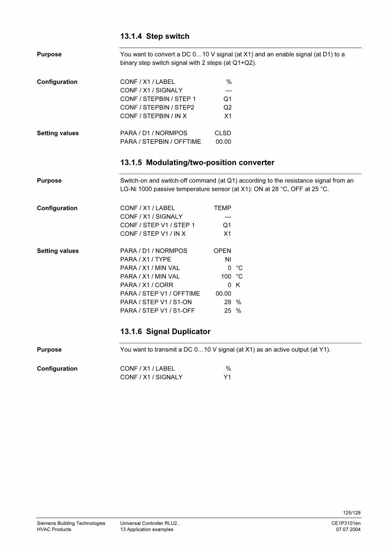
125/128
Siemens Building Technologies Universal Controller RLU2… CE1P3101en
HVAC Products 13 Application examples 07.07.2004
13.1.4 Step switch
You want to convert a DC 0…10 V signal (at X1) and an enable signal (at D1) to a
binary step switch signal with 2 steps (at Q1+Q2).
CONF / X1 / LABEL %
CONF / X1 / SIGNALY ---
CONF / STEPBIN / STEP 1 Q1
CONF / STEPBIN / STEP2 Q2
CONF / STEPBIN / IN X X1
PARA / D1 / NORMPOS CLSD
PARA / STEPBIN / OFFTIME 00.00
13.1.5 Modulating/two-position converter
Switch-on and switch-off command (at Q1) according to the resistance signal from an
LG-Ni 1000 passive temperature sensor (at X1): ON at 28 °C, OFF at 25 °C.
CONF / X1 / LABEL TEMP
CONF / X1 / SIGNALY ---
CONF / STEP V1 / STEP 1 Q1
CONF / STEP V1 / IN X X1
PARA / D1 / NORMPOS OPEN
PARA / X1 / TYPE NI
PARA / X1 / MIN VAL 0 °C
PARA / X1 / MIN VAL 100 °C
PARA / X1 / CORR 0 K
PARA / STEP V1 / OFFTIME 00.00
PARA / STEP V1 / S1-ON 28 %
PARA / STEP V1 / S1-OFF 25 %
13.1.6 Signal Duplicator
You want to transmit a DC 0…10 V signal (at X1) as an active output (at Y1).
CONF / X1 / LABEL %
CONF / X1 / SIGNALY Y1
Purpose
Configuration
Setting values
Purpose
Configuration
Setting values
Purpose
Configuration

126/128
Siemens Building Technologies Universal Controller RLU2… CE1P3101en
HVAC Products Index 07.07.2004
Index
A
Abbreviations used in this document.......................106
Access level, select ...................................................12
Alarm acknowledgement .........................................103
Alarm list..................................................................102
Application examples
Modulating/two-position converter .....................125
Multiple sensor use ............................................124
Signal adaptation ...............................................124
Signal duplicator ................................................125
Signal inversion..................................................124
Step switch.........................................................125
B
Basic configuration, choosing....................................16
Basic types A and U ..................................................20
Bedientexte (Kürzelliste) .........................................107
C
Configuration
Configuration diagrams......................................116
Explanation of the configuration principle ..........111
Function block overview.....................................112
Control strategies ......................................................63
Controller (CTLOOP x)..............................................62
Controller configuration procedure ............................62
Controller with changeover
Individual room control example ..........................78
Primary controller.................................................75
D
Data point, term.........................................................11
Deviation message (DV ALM) ...................................93
Display symbols ........................................................10
E
Electrical connections
Connection rules ................................................104
Connection terminals .........................................105
F
Fan release ...............................................................22
Frost protection (FROST)
2-stage frost protection examples........................97
Acknowledgement................................................99
Connection diagrams .........................................100
Description ...........................................................95
Frost monitor example .........................................96
H
HREC
Description ...........................................................40
I
Input identifiers ......................................................... 23
Inputs
Analog X1…X5.................................................... 24
Digital (D1, D2, X1…X5) ..................................... 28
Universal (X1…X5) ............................................. 23
L
Limit control of individual sequences (SEQ)............. 86
Limit control, general (LIM)....................................... 84
Locking of sequences according to OT .................... 89
M
MECH
Description .......................................................... 41
Possibilities ................................................... 42, 45
Menu structure.......................................................... 13
O
Operating level, change............................................ 11
Output, modulating (AO x)........................................ 38
Outside temperature (OUTS) ................................... 33
P
Pump (PUMP x)
Frost protection pump, example.......................... 37
Load-dependent recooling pump, example......... 37
Pumpe (PUMP x)
Description .......................................................... 35
R
Remote setpoint, absolute (REM) ............................ 29
Remote setpoint, relative (REL) ............................... 31
Room mode selection............................................... 20
Room temperature (ROOM): .................................... 34
Room temperature control........................................ 65
Room/supply air temperature cascade controller ..... 66
S
Sequence controller
Control parameters ............................................. 81
Load outputs ....................................................... 80
Pump outputs ...................................................... 81
Sequence controllers
Output assignments ............................................ 79
Setpoint shift, universal ............................................ 91
Settings, general....................................................... 19
Step switch
Binary (STEPBIN) ............................................... 56
Linear (STEPLIN)................................................ 52
Variable (STEP Vx) ............................................. 49
Summer/winter compensation .................................. 90
Supply air temperature control ................................. 70

127/128
Siemens Building Technologies Universal Controller RLU2… CE1P3101en
HVAC Products Index 07.07.2004
T
Three-position output (3-POINT) ..............................60
U
Universal controller
Chilled ceiling example ........................................72
Description...........................................................72
Solar plant example .............................................72

128/128
Siemens Building Technologies Universal Controller RLU2… CE1P3101en
HVAC Products Index 07.07.2004
Siemens Building Technologies AG
HVAC Products
Gubelstrasse 22
CH-6301 Zug
Tel. +41 41-724 24 24
Fax +41 41-724 35 22
www.landisstaefa.com
© 2004 Siemens Building Technologies AG
Subject to alteration