200-P PTO-Driven Compressor Kit Operation Guide · A. How It Works ... which allows the air...
29
Waterous Company, 125 Hardman Avenue South, South St. Paul, Minnesota 55075 USA (651) 450-5000 www.waterousco.com 200-P PTO-Driven Compressor Kit Operation Guide Read through the operation instructions carefully. NOTE: Instructions subject to change without notice. Table of Contents SECTION 1. OPERATING INSTRUCTIONS ................................................. 4 A. Power-Up Procedure ........................................................................... 4 B. Multiple Uses ....................................................................................... 5 C. For Electric Auto-Sync ......................................................................... 5 I. Water Pumping Operations ............................................................ 5 II. Foam Solution Operations ............................................................. 6 III. Compressed Air Foam Operations................................................. 6 IV. Compressed Air Only Operation .................................................... 7 D. Shut-Down Procedure ......................................................................... 8 SECTION 2. COMPRESSOR......................................................................... 9 A. How It Works ....................................................................................... 9 SECTION 3. AIR COMPRESSOR SYSTEM SERVICE AND MAINTENANCE ......... 10 SECTION 4. SERVICE AND MAINTENANCE ............................................. 11 A. Maintenance Schedule ...................................................................... 11 B. Maintenance Items ............................................................................ 11 C. Wye Strainer for Cooler ..................................................................... 11 SECTION 5. CAFS NOZZLE / FLOW RATE / HOSE COMBINATIONS ...... 13 A. Nozzles .............................................................................................. 13 B. Foam Concentrate Ratios.................................................................. 13 C. Hose .................................................................................................. 13 SECTION 6. SUGGESTED GUIDELINES PRODUCTION OF MID-RANGE COMPRESSED AIR FOAM ............................................................................... 14 A. 1” (25 mm) Hose Diameter Jacketed................................................. 14 B. 1-1/2” (38 mm) Hose Diameter .......................................................... 14 C. 1-3/4” (44 mm) Hose Diameter .......................................................... 15 D. Master Stream ................................................................................... 16 SECTION 7. TROUBLESHOOTING - CAFS ............................................... 17 SECTION 8. CONDITIONAL 5-YEAR WARRANTY POLICY ...................... 29 F-1031, Section 2422 (Revised 02/04/10)
-
Upload
phungtuyen -
Category
Documents
-
view
216 -
download
0
Transcript of 200-P PTO-Driven Compressor Kit Operation Guide · A. How It Works ... which allows the air...

Waterous Company, 125 Hardman Avenue South, South St. Paul, Minnesota 55075 USA (651) 450-5000 www.waterousco.com
200-P PTO-Driven Compressor KitOperation Guide
Read through the operation instructions carefully.
NOTE: Instructions subject to change without notice.
Table of Contents
SECTION 1. OPERATING INSTRUCTIONS ................................................. 4 A. Power-Up Procedure ........................................................................... 4 B. Multiple Uses ....................................................................................... 5 C. For Electric Auto-Sync ......................................................................... 5
I. Water Pumping Operations ............................................................ 5 II. Foam Solution Operations ............................................................. 6 III. Compressed Air Foam Operations ................................................. 6 IV. Compressed Air Only Operation .................................................... 7
D. Shut-Down Procedure ......................................................................... 8 SECTION 2. COMPRESSOR......................................................................... 9
A. How It Works ....................................................................................... 9 SECTION 3. AIR COMPRESSOR SYSTEM SERVICE AND MAINTENANCE ......... 10 SECTION 4. SERVICE AND MAINTENANCE ............................................. 11
A. Maintenance Schedule ...................................................................... 11 B. Maintenance Items ............................................................................ 11 C. Wye Strainer for Cooler ..................................................................... 11
SECTION 5. CAFS NOZZLE / FLOW RATE / HOSE COMBINATIONS ...... 13 A. Nozzles .............................................................................................. 13 B. Foam Concentrate Ratios .................................................................. 13 C. Hose .................................................................................................. 13
SECTION 6. SUGGESTED GUIDELINES PRODUCTION OF MID-RANGE COMPRESSED AIR FOAM ............................................................................... 14
A. 1” (25 mm) Hose Diameter Jacketed ................................................. 14 B. 1-1/2” (38 mm) Hose Diameter .......................................................... 14 C. 1-3/4” (44 mm) Hose Diameter .......................................................... 15 D. Master Stream ................................................................................... 16
SECTION 7. TROUBLESHOOTING - CAFS ............................................... 17 SECTION 8. CONDITIONAL 5-YEAR WARRANTY POLICY ...................... 29
F-1031, Section 2422 (Revised 02/04/10)

F-1031- Section 2422 Page 2 of 29
Warnings, Cautions, and Notes Warning A warning alerts you to a procedure, practice or condition that may result in death or long
term injury to personnel or destruction of equipment.
Caution A caution alerts you to a procedure or condition that may result in serious damage to equipment or its failure to operate as expected
Note: A note points out important information. Failure to read the note may not result in physical
harm to personnel or equipment. It may waste time and money. Revision History
Revision Date Issued Comments --- 03/06 Original Release 1 9/26/2006 Reformatted, new logo, added T/S Guide CAFS,
rem Auto-sync adj section, chg maintenance item chart, updated Basic CAFS pic
3/9/2009 Updated Air schematics 02/04/10 added “Run compressor 15 minutes
Disclaimer: These instructions are guidelines only and in no way meant to be definitive. During installation, standard safety precautions and equipment should be used where appropriate. Because the tools used and the skill/experience of the installer can vary widely, it is impossible to anticipate all conditions under which this installation is made, or to provide cautions for all possible hazards. Proper installation is the responsibility of the purchaser. All bolts, setscrews, and belts must be checked prior to start-up AND after the initial operation. Damages due to poor installation are the responsibility of the installer. Waterous reserves the right to make modifications to the system without notice

F-1031- Section 2422 Page 3 of 29
Figure(s) Figure 1 Electric Auto-sync panel ................................................................................................................ 5 Figure 2 Wye Strainer ................................................................................................................................. 12 Figure 3 Wye-strainer installed, with cleanout valve. ................................................................................ 12 Figure 4 Clean Strainer .............................................................................................................................. 12 Figure 5 Dirty Strainer ................................................................................................................................ 12 Figure 6 Basic CAFS Schematic ............................................................................................................... 21 Figure 7 CF75G Dimensions ..................................................................................................................... 22 Figure 8 Hydraulic Schematic w/ Tee Sump .............................................................................................. 23 Figure 9 Hydraulic Schematic, Vertical Sump ........................................................................................... 24 Figure 10 Air Schematic, Electric Auto-sync, 90° Inlet .............................................................................. 25 Figure 11 Electric Auto-Sync Schematic ................................................................................................... 26 Figure 12 Air Schematic, Electric Auto-sync, Vertical Inlet ........................................................................ 27 Figure 13 Compressor Installation Angles ................................................................................................. 28

F-1031- Section 2422 Page 4 of 29
SECTION 1. OPERATING INSTRUCTIONS
A. Water Pumping Operations
All unit operations begin with pumping water. Follow the instructions provided in the apparatus manuals for operations involving pumping water. For water only operations, the compressor can be left in the UNLOAD position (which puts the compressor in standby mode) or PTO shift control could be in the "OFF" position, which disengages the air compressor.
CAUTION: Running the unit with a dry fire pump can cause damage to the pump and air compressor system.
B. Power-Up Procedure
• Verify Auto-Sync is in UNLOAD position.
• Engage the air compressor by moving the PTO switch to the "ON" position.
• Verify Foam Proportioner is on.
• Move the Auto-Sync controls to the AUTO position. Bring Water pressure to approximately 100-120 PSI. Air pressure as shown on the air pressure gauge should rise to within plus or minus 5% of the water discharge pressure. The Auto-Sync system will balance the air and water pressures + or - 5% throughout a range of 40 PSI up to 150 PSI.
• Set proportioner at 0.2% - 0.6% for normal Class A combustibles. Proportioning rates are
dictated by the type and brand of foam concentrate used and the tactical objective.
• Open desired air and/or water discharge valve(s) by moving the handle approximately 1/2 from the closed position. The foam expansion ratio is set by controlling the amount of foam solution entering the discharge stream. High solution flows restrict the amount of air admitted and result in lower expansion or "wet" foam. To produce higher expansion or "drier" foam, simply gate back the amount of solution admitted.
• Fully open the air valve(s) to the desired discharges. Adjust the solution flow to produce the
desired foam consistency. Foam is formed during the transition through the hose. To produce acceptable finished foam, sufficient hose length must be provided on the discharge. Refer to page 8 for minimum hose lengths for CAFS operations.
WARNING Nozzle reaction force is significantly increased at the time the nozzle valve is opened in compressed air foam operations. OPEN CAFS NOZZLES SLOWLY!

F-1031- Section 2422 Page 5 of 29
C. Multiple Uses The Waterous modular compressed air foam unit can be operated in several pumping modes; water only, foam solution without compressed air, compressed air foam and compressed air only for support operations such as operating air tools, filling rescue air bags, etc. It is possible to pump foam solution from one discharge while pumping compressed air foam from another, or varying foam consistencies (expansion ratios) from different discharges simultaneously. NOTE: Monitor engine and compressor instruments during any and all operations.
D. For Electric Auto-Sync
Figure 1 Electric Auto-sync panel
I. Water Pumping Operations
All unit operations begin with pumping water. These steps must be followed for operations involving pumping water, foam solution, compressed air or compressed air foam. • Connect the hose(s) to the desired discharge(s).
WARNING: Prior to starting the engine, the Auto Sync controls should be in the UNLOAD position, which allows the air compressor to “free wheel” without pumping air. If pumping water from an on board booster tank, fully open the tank to pump valve.
If pumping from an overboard source, the tank to pump valve should be fully closed.
If so equipped, turn on the main power switch to the CAFS unit.
Open desired discharge valves and throttle-up to desired pressure.

F-1031- Section 2422 Page 6 of 29
CAUTION: Running the unit with a dry fire pump can cause damage to the pump and air compressor system.
II. Foam Solution Operations
Follow the instructions above for water pumping operations. Turn on the foam proportioner to inject foam concentrate into the water stream. Refer to the foam proportioner operation manual for instructions in the proper operation of the installed proportioning system.
III. Compressed Air Foam Operations
Follow the instructions above for foam solution operations. Safe operations dictate the presence of foam concentrate in the water stream prior to the injection of compressed air. If foam concentrate is not present, a condition known as “slug flow” will occur. This is where unmixed water and air is discharged through a nozzle in an erratic manner. • Set water discharge pressure at the desired level. Discharge pressures for compressed air
foam operations typically range between 80 and 120 PSI in a flow state. NOTE: Compressed air foam does not have the hydraulic characteristics of plain water or foam
solution. Therefore, standard pump hydraulics practices do not apply to CAFS operations.
Move Auto-Sync controls to the AUTO position.
Air pressure as shown on the air pressure gauge should rise to within plus or minus 5% of the water discharge pressure. The Auto-Sync system will balance the air and water pressures throughout a range of 40 PSI up to 150 PSI. Optimal compressed air foam system performance occurs at discharge flow pressures of 80-120 PSI.
Set proportioner at 0.2% - 0.6% for normal Class A combustibles.
The type and brand of foam concentrate used and the tactical objective dictate proportioning rates.
Open desired discharge valves by pulling the “TEE” handle approximately 1-1/2” from the
closed position. Controlling the amount of foam solution entering the discharge stream sets the foam expansion ratio. High solution flows restrict the amount of air admitted and result in lower expansion or “wet” foam. To produce higher expansion or “drier” foam, simply gate back the amount of solution admitted.

F-1031- Section 2422 Page 7 of 29
Fully open the air valve(s) to the desired discharge(s).
Adjust the solution flow to produce the desired foam consistency.
Foam is formed during the transition through the hose. To produce acceptable finished foam, sufficient hose length must be provided on the discharge. Refer to the section “Suggested Guidelines for the Production of Mid-Range Compressed Air Foam”.
WARNING: Nozzle reaction force is significantly increased at the time the nozzle valve is opened in
compressed air foam operations. OPEN CAFS NOZZLES SLOWLY!
IV. Compressed Air Only Operation
Follow instructions for water pumping operations without opening discharge valves. Air compressor cooling is via water that is circulated by the fire pump through the compressor cooler and returned back to the booster tank. During this operation, time is limited by the amount of available cooling water. The water in the booster tank will eventually become heat saturated and ineffective at cooling the air compressor. Watch the compressor temperature gauge closely! Maximum of 250°F. Compressor system overheat is also indicated by the panel mounted warning light and alarm. After engine start, ensure that the water pressure as shown on the panel mounted gauge
rises. Move Auto-Sync control to the FIXED position. Air pressure will rise to the preset pressure
setting on the air compressor, approximately 150-PSI with the engine throttled-up. For lower operating pressures, move the Auto-Sync controls to the AUTO position and use
the engine throttle to control the water pressure / air pressure Connect the air discharge hose to the fitting on the pump operator’s panel and open the air
supply valve. Extended compressed air only operations necessitate connection of an external water source to the pump inlet and closing of the tank to pump valve far proper compressor cooling. In this case, cooling water will flow into the booster tank at 10-20 GPM, eventually overflowing the tank.

F-1031- Section 2422 Page 8 of 29
WARNINGS • Compressed air can be dangerous. Read and understand the operating
instructions for the Waterous compressed air foam unit and individual components prior to operating.
• DO NOT use the compressed air foam unit as an air source for SCBA or any
breathing air supply. • Discharge outlets that are capped, hose lines that are valved and charged and the
air compressor sump may contain compressed air. Relieve all pressure BEFORE attempting to remove any caps, fittings, and nozzles or to perform maintenance to prevent serious personal injury.
• Nozzle reaction force is significantly increased at the time the nozzle valve is
opened in compressed air foam operations. OPEN CAFS NOZZLES SLOWLY! • Operating the compressed air foam unit with water and compressed air pumped
through a discharge without foam concentrate will create a potentially dangerous condition known as "Slug Flow"; where unmixed pockets of water and air are passed through the nozzle, causing erratic nozzle reaction.
• For compressed air foam operations, use only fire hose that is rated at 200 PSI or
higher working pressure. • The unit operator should have a thorough understanding of "Boyle's Law" (The
law of compressed gases) prior to operating the compressed air foam unit.
E. Shut-Down Procedure • Close air valve(s) • Turn off Foam proportioner • Flow clear water through discharge hose(s) until no bubbles are present • Close discharge valve(s) • Move Auto-Sync controls to UNLOAD • Move the air compressor PTO switch to the "OFF" position After the compressor PTO is disengaged, the system will vent itself, creating an audible hiss as compressed air is evacuated from the pressure vessel / sump. CAUTION: Allow system to bleed down the pressures for approximately 2-3 minutes prior
to re-engaging. Otherwise, re-engagement may cause engine to stall.

F-1031- Section 2422 Page 9 of 29
SECTION 2. COMPRESSOR
A. How It Works The air compressor used in this application is a GHH Rand model CF75G, oil flooded rotary screw type. Rotary screw air compressors are very common in industrial applications. This type of compressor injects oil into itself, where it lubricates, seals, cools, and silences the compressor. The oil is then entrained into the air discharge from the compressor. This air/oil mixture is discharged into a sump tank where most of the oil separates from the air. The oil is then sent via hydraulic hose to a combination cooler / filter unit. It is cooled to remove compression and friction heat, filtered, and sent to the oil injection port on the compressor. The cycle is then repeated. The oil mist that remains in the air stream is recovered by an air/oil separator system. This system recovers the oil mist in a spin-on cartridge that has a siphon tube that picks-up the recovered oil for return to the air compressor. The compressor's air output is controlled by a modulating inlet valve. The inlet valve is opened and closed by the Auto-Sync pressure control system. The compressor cooling system circulates water from the fire pump through the compressor oil cooler and back to the tank to remove heat from the compressor oil system. The compressor oil temperature should not exceed 250° F. If this occurs, check the water supply; pump prime, restrictions in the cooling water system and for low oil level in the sump. The air compressor (air end) is driven via a transmission power take-off. It is important to ensure that there is a water supply from the fire pump whenever the engine is running. Pump and/or compressor damage may result from running the pump dry.

F-1031- Section 2422 Page 10 of 29
SECTION 3. AIR COMPRESSOR SYSTEM SERVICE AND MAINTENANCE
Excessive heat build-up and oil system contamination are the most common causes of compressor system problems and premature wear. With proper operation and maintenance, the compressor system should far outlast the vehicle it is mounted on. Adherence to the following guidelines will prevent potentially costly damage. 1. There is a sight gauge provided on the oil reservoir/sump. The oil level should be at approximately
halfway up the window. Check the oil on level ground, prior to system start up. If the system has recently been run, wait 10 minutes after shutdown for the oil to stabilize before checking the oil level. The compressor uses common hydraulic oil. This oil is classified by an ISO standard as ISO 68 viscosity and is sold under various trade names. Many are sold as "anti wear" hydraulic oil and are available from auto parts or lubricating oil suppliers.
2. The oil should be changed after the first 30 hours of system operation. After that, the oil should be
changed annually. There is a drain plug located at the bottom of the sump. The oil fill cap is located on top of the unit.
3. Change the compressor system oil filter at the same time as the oil is changed. (See page 9 for
replacement filters). 4. Run the compressor for 2 minutes after changing the oil, then re-check the oil level and add oil as
necessary. DO NOT OVERFILL. 5. Visually inspect the compressor oil system weekly for signs of leaks. 6. Inspect the compressor air intake filter and clean or replace as necessary. The environment in
which the unit operates will determine the frequency of air filter service and replacement. In any situation, replace no less frequently than yearly.
7. Replace the oil / air separator cartridge every 24 months, or if the unit's oil consumption suddenly
increases. A sudden increase may be caused by a hole in the internal media of the cartridge allowing oil to carry through and discharge with the compressed air. Call Waterous for replacement separator cartridges.
8. Completely drain the water from the compressor oil cooler in cold weather to prevent freeze
damage.

F-1031- Section 2422 Page 11 of 29
SECTION 4. SERVICE AND MAINTENANCE
A. Maintenance Schedule
Check oil level and for
oil leaks
Change Compressor
Oil Change Oil
Filter Change
Separator Cartridge
Run Air system 15 minutes per
Compressed Air Only Operation
Daily or After Each Use X Weekly X- pg 7 Annually X X Every 24 Months X
Refer to the Engine Manual for recommended engine maintenance. Inspect the air compressor air intake filter and change as necessary (at least once monthly).
B. Maintenance Items
COMPRESSOR Part#
AIR FILTER: CO85004 (1) 2030042SEPARATOR FILTER: LB 13 145/3 (2) 2030049HYDRAULIC FILTER: WD962 (2) 2030060
HYDRAULIC OIL ISOAUW68 Anti-Wear, Low-Foaming, Anti-Foaming
(1) = Donaldson (2) = Mann & Hummel
C. Wye Strainer for Cooler A wye-strainer is provided to strain water before it enters the cooler's water inlet. The wye strainer requires regular inspection, and should be in an easily accessible location for inspection, removal, and cleaning.
Caution: Waterous is not responsible for damage due to plugged strainers. If the customer's water system contains excessive debris, or the vehicle relies on drafting for its water supply, it may be necessary to install a larger strainer and/or a clean-out valve on the wye-strainer.
Without good water flow through the heat exchanger, the compressor will overheat. Compressor performance will be inadequate, and it may fail completely. Omitting the Wye-strainer or removing the screen from the Wye does not improve water flow. It will allow debris into the cooler, which can clog the tiny heat exchanger tubes and restrict water flow.

F-1031- Section 2422 Page 12 of 29
Figure 2 Wye Strainer Figure 3 Wye-strainer installed, with cleanout valve.
Figure 4 Clean Strainer Figure 5 Dirty Strainer

F-1031- Section 2422 Page 13 of 29
SECTION 5. CAFS NOZZLE / FLOW RATE / HOSE COMBINATIONS
A. Nozzles Compressed air foam can be discharged through various types and sizes of nozzles. Fog nozzles break down the bubble structure of the foam, resulting in "wetter" or reduced expansion foam. The preferred way to make foam is utilizing smooth bore nozzles with a given hose diameter. Smaller tips will discharge "wetter" foam.
B. Foam Concentrate Ratios Proportioner settings of 0.2% and 0.6% are typically adequate to produce compressed air foam that is formed in a hose line and used on Class A combustibles. Higher settings will result in "drier" appearing foam. Lower settings may result in "slug flow" or discharge pulsation caused by insufficient foam concentrate in solution to form foam in the hose line. For Class B or other type foam ratio settings, follow the instructions provided by the foam concentrate manufacturer.
C. Hose Utilize fire hose that is rated by the hose manufacturer for use with CAFS. Since the foam is formed during its transition through the hose line, it is important to utilize the minimum recommended hose lengths, unless a static mixer is utilized. There is significantly less friction and head loss with compressed air foam as compared to water or foam solution. Hence, effective fire streams can be achieved with longer hose layouts. Refer to the section, “Suggested Guidelines for the Production of Mid-Range Compressed Air Foam”. NOTE: Compressed air foam systems have the ability to produce foam of shaving cream consistency.
This type of foam is typically suited for defensive operations such as exposure protection, barriers or fuels pretreatment. While this type of foam is highly stable and possesses a long drain time, it is essential to ensure that the foam will release sufficient water to extinguish a fire in a direct attack situation.

F-1031- Section 2422 Page 14 of 29
SECTION 6. SUGGESTED GUIDELINES FOR THE PRODUCTION OF MID-RANGE COMPRESSED AIR FOAM
A. 1” (25 mm) Hose Diameter Jacketed 1 GPM to 1 CFM ½” Tip Solution Flow: 15 GPM (56.78 LPM) Air Flow: 15 CFM (0.42 m3/min) Disch. Pressure: 100-150 PSI (6.804 - 10.206 BAR) (689.5 - 1034.25 KPA) Min/Max Hose Length: 35’ to over 400’ (10.668 – 121.92 meters) 2 GPM to 1 CFM ½” Tip Solution Flow: 30 GPM (113.56 LPM) Air Flow 15 CFM (0.42 m3/min) Disch. Pressure: 100-150 PSI (6.804 - 10.206 BAR) (689.5 - 1034.25 KPA) Min/Max Hose Length: 35’ to over 400’ (10.668 – 121.92 meters) 1 GPM to 1 CFM ¾” Tip Solution Flow: 20 GPM (75.71 LPM) Air Flow: 20 CFM (0.56 m3/min) Disch. Pressure: 100-150 PSI (6.804 - 10.206 BAR) (689.5 - 1034.25 KPA) Min/Max Hose Length: 35’ to over 200’ (10.668 – 60.96 meters) 2 GPM to 1 CFM ¾” Tip Solution Flow: 40 GPM (151.41 LPM) Air Flow: 20 CFM (0.56 m3/min) Disch. Pressure: 100-150 PSI (6.804 - 10.206 BAR) (689.5 - 1034.25 KPA) Min/Max Hose Length: 35’ to over 200’ (10.668 – 60.96 meters)
B. 1-1/2” (38 mm) Hose Diameter 1 GPM to 1 CFM 1” Tip Solution Flow: 30-40 GPM (113.56 – 151.41 LPM) Air Flow: 30-40CFM (0.84 – 1.12 m3/min) Disch. Pressure: 100-150 PSI (6.804 - 10.206 BAR) (689.5 - 1034.25 KPA) Min/Max Hose Length: 100’ to over 800’ (30.48 – 243.84 meters)

F-1031- Section 2422 Page 15 of 29
2 GPM to 1 CFM 1” Tip Solution Flow: 60-80 GPM (227.12 – 302.82 LPM) Air Flow: 30-40CFM (0.84 – 1.12 m3/min) Disch. Pressure: 100-150 PSI (6.804 - 10.206 BAR) (689.5 - 1034.25 KPA) Min/Max Hose Length: 100’ to over 800’ (30.48 – 243.84 meters) 1 GPM to 1 CFM 1-3/8” Tip Solution Flow: 50-60 GPM (189.27 – 227.12 LPM) Air Flow: 50-60 CFM (1.4 – 1.68 m3/min) Disch. Pressure: 100-150 PSI (6.804 - 10.206 BAR) (689.5 - 1034.25 KPA) Min/Max Hose Length: 100’ to over 800’ (30.48 – 243.84 meters) 2 GPM to 1 CFM 1-3/8” Tip Solution Flow: 90-120 GPM (340.68 – 454.24 LPM) Air Flow: 50-60 CFM (1.4 – 1.68 m3/min) Disch. Pressure: 100-150 PSI (6.804 - 10.206 BAR) (689.5 - 1034.25 KPA) Min/Max Hose Length: 100’ to over 800’(30.48 – 243.84 meters)
C. 1-3/4” (44 mm) Hose Diameter 1 GPM to 1 CFM 1” Tip Solution Flow: 30-40 GPM (113.56 – 151.41 LPM) Air Flow: 30-40 CFM (0.84 – 1.12 m3/min) Disch. Pressure: 100-150 PSI (6.804 - 10.206 BAR) (689.5 - 1034.25 KPA) Min/Max Hose Length: 100’ to over 1400’ (30.48 – 426.72 meters) 2 GPM to 1 CFM 1” Tip Solution Flow: 60-90 GPM (227.12 – 340.68 LPM) Air Flow: 30-50 CFM (0.84 – 1.4 m3/min) Disch. Pressure: 100-150 PSI (6.804 - 10.206 BAR) (689.5 - 1034.25 KPA) Min/Max Hose length: 100’ to over 1400’ (30.48 – 426.72 meters) 1-3/8” Tip Solution Flow: 50-90 GPM (189.27 – 340.68 LPM) Air Flow: 50-80 CFM (1.4 – 2.24 m3/min) Disch. Pressure: 110-150 PSI (7.4844- 10.206 BAR) (758.45- 1034.25 KPA) Min/Max Hose Length: 100’ to over 700’ (30.48 – 213.36 meters)
NOTE: With 1-3/4” hose lengths of 100’-250’ (30.48 – 76.2 meters), up to 90-120 GPM (340.68 – 454.24 LPM) of water and 40-100 CFM (1.12 – 2.8 m3/min) of air may be utilized as a highly effective initial attack flow.
System flows are very flexible. The flow of any discharge can vary according to the situation and conditions. It is possible to make the discharge stream wetter or drier by changing the amount of solution or air in the hose.

F-1031- Section 2422 Page 16 of 29
The stream can also vary by changing the tip size at the nozzle. • The bigger the diameter tip, the drier the foam. • The smaller the diameter tip, the wetter the foam.
D. Master Stream 1” Tip Solution Flow: 90-120 GPM (340.68 – 454.24 LPM) Air Flow: 60-80 CFM (1.68 – 2.24 m3/min) 1-3/8” Tip Solution Flow: 100-150 GPM (378.53 – 567.80 LPM) Air Flow: 70-100 CFM (1.96 – 2.8 m3/min) 1-1/2” Tip Solution Flow: 120-200 GPM (454.24 – 757.06 LPM) Air Flow: 80-120 CFM (1.68 – 3.36 m3/min) 1-3/4” Tip Solution Flow: 180-250 GPM (681.35 – 946.33 LPM) Air Flow: 120-150 CFM (3.36 – 4.2 m3/min) 2” Tip Solution Flow: 250-450 GPM (946.33 – 1703.39 LPM) Air Flow: 200 CFM (5.6 m3/min) Disch. Pressure: 120-150 PSI (8.1648 – 10.206 BAR) (827.4 – 1034.25 KPA)
NOTE: Typical master stream operations utilize lower foam expansion ratios ("wetter" foam) for
increased foam density and longer stream reach.
F-1031- Section 2422 Page 17 of 29
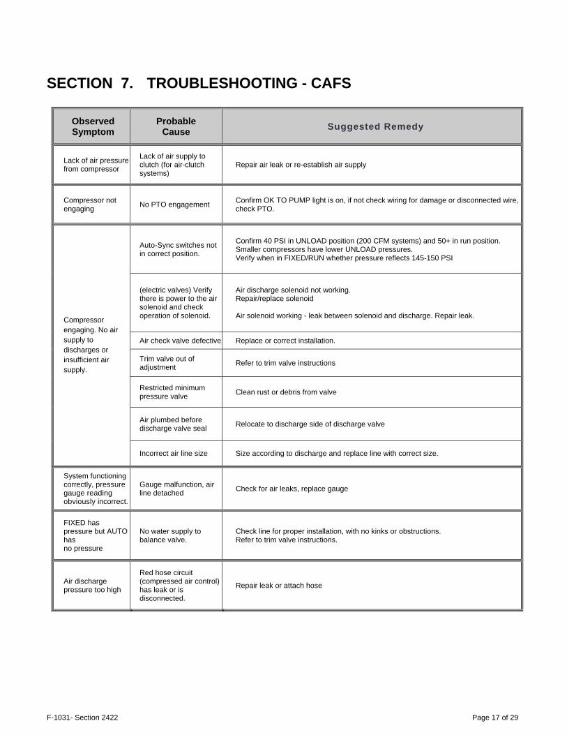
SECTION 7. TROUBLESHOOTING - CAFS
Observed Symptom
Probable Cause Suggested Remedy
Lack of air pressure from compressor
Lack of air supply to clutch (for air-clutch systems)
Repair air leak or re-establish air supply
Compressor not engaging No PTO engagement Confirm OK TO PUMP light is on, if not check wiring for damage or disconnected wire,
check PTO.
Compressor engaging. No air supply to discharges or insufficient air supply.
Auto-Sync switches not in correct position.
Confirm 40 PSI in UNLOAD position (200 CFM systems) and 50+ in run position. Smaller compressors have lower UNLOAD pressures. Verify when in FIXED/RUN whether pressure reflects 145-150 PSI
(electric valves) Verify there is power to the air solenoid and check operation of solenoid.
Air discharge solenoid not working. Repair/replace solenoid Air solenoid working - leak between solenoid and discharge. Repair leak.
Air check valve defective Replace or correct installation.
Trim valve out of adjustment Refer to trim valve instructions
Restricted minimum pressure valve Clean rust or debris from valve
Air plumbed before discharge valve seal Relocate to discharge side of discharge valve
Incorrect air line size Size according to discharge and replace line with correct size.
System functioning correctly, pressure gauge reading obviously incorrect.
Gauge malfunction, air line detached Check for air leaks, replace gauge
FIXED has pressure but AUTO has no pressure
No water supply to balance valve.
Check line for proper installation, with no kinks or obstructions. Refer to trim valve instructions.
Air discharge pressure too high
Red hose circuit (compressed air control) has leak or is disconnected.
Repair leak or attach hose
F-1031- Section 2422 Page 18 of 29
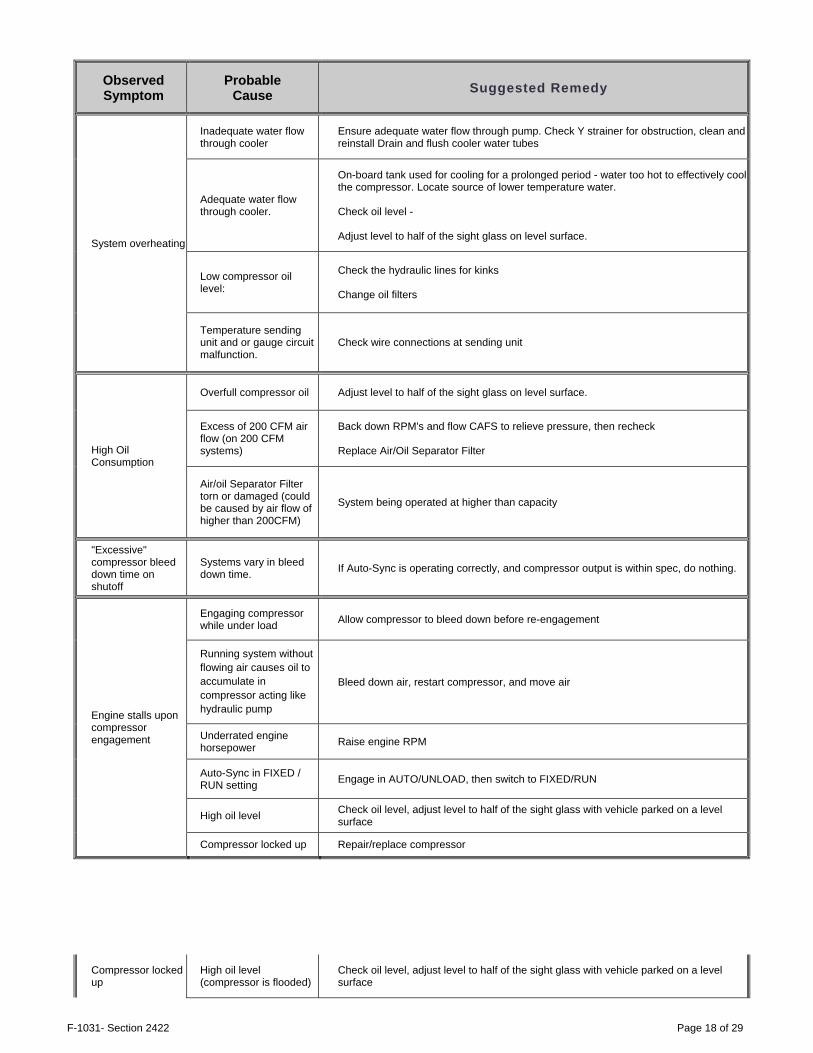
Observed Symptom
Probable Cause Suggested Remedy
System overheating
Inadequate water flow through cooler
Ensure adequate water flow through pump. Check Y strainer for obstruction, clean and reinstall Drain and flush cooler water tubes
Adequate water flow through cooler.
On-board tank used for cooling for a prolonged period - water too hot to effectively cool the compressor. Locate source of lower temperature water. Check oil level - Adjust level to half of the sight glass on level surface.
Low compressor oil level:
Check the hydraulic lines for kinks Change oil filters
Temperature sending unit and or gauge circuit malfunction.
Check wire connections at sending unit
High Oil Consumption
Overfull compressor oil Adjust level to half of the sight glass on level surface.
Excess of 200 CFM air flow (on 200 CFM systems)
Back down RPM's and flow CAFS to relieve pressure, then recheck Replace Air/Oil Separator Filter
Air/oil Separator Filter torn or damaged (could be caused by air flow of higher than 200CFM)
System being operated at higher than capacity
"Excessive" compressor bleed down time on shutoff
Systems vary in bleed down time. If Auto-Sync is operating correctly, and compressor output is within spec, do nothing.
Engine stalls upon compressor engagement
Engaging compressor while under load Allow compressor to bleed down before re-engagement
Running system without flowing air causes oil to accumulate in compressor acting like hydraulic pump
Bleed down air, restart compressor, and move air
Underrated engine horsepower Raise engine RPM
Auto-Sync in FIXED / RUN setting Engage in AUTO/UNLOAD, then switch to FIXED/RUN
High oil level Check oil level, adjust level to half of the sight glass with vehicle parked on a level surface
Compressor locked up Repair/replace compressor
Compressor locked up
High oil level (compressor is flooded)
Check oil level, adjust level to half of the sight glass with vehicle parked on a level surface

F-1031- Section 2422 Page 19 of 29
Observed Symptom
Probable Cause Suggested Remedy
Sump fire Check system and repair
Low oil level or no oil Check system and repair
Air flow meter stuck at "0" CFM
Magnet uncoupled in meter Turn air flow on and off to re-couple
Air flow meter stuck at high CFM Move large amounts of air out discharge and turn air flow on and off to re-couple
Poor foam (wet or dry) or no foam (assuming air pressure to discharges is OK)
Using wetting agent and not foam concentrate. Use foam concentrate
Foam proportioning control turned too low. Increase amount of concentrate delivered to manufacturer recommended amount.
Foam proportioning control OFF or turned too low, foam tank empty.
Make sure proportioner is turned on, foam supply valve is open, foam tank has concentrate, Y strainer is clean, and supply line is connected to injector.
Discharge hose shaking (slug flow)
Foam proportioner ON, setting correct, and tank has foam concentrate, but not providing foam solution.
Refer to foam proportioner manufacturer's instructions for detailed calibration and troubleshooting instructions
Foam in the water system (when proportioner turned off)
Foam concentrate was poured into the on-board water tank
Flush tank and pump with clean water, refill
Foam manifold drain lines not isolated from water drain lines
Isolate to separate drain valve
Cooler line plumbed from foam manifold Relocate line to discharge side of pump
Foam manifold check valve defective Rebuild/replace check valve
Water in compressor oil/air
Leaking inside cooler Freeze damage Isolate cooler and check for leaks, replace if needed, check drain
Defective air check valves Replace or check
Missing air check valves for discharges Install check valves
Clutch smoking
Engaging in RUN position Engage in AUTO/UNLOAD only
Slight air leak from solenoid to clutch Repair air leak
F-1031- Section 2422 Page 20 of 29
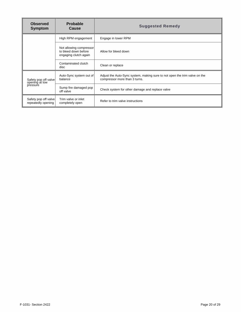
Observed Symptom
Probable Cause Suggested Remedy
High RPM engagement Engage in lower RPM
Not allowing compressor to bleed down before engaging clutch again
Allow for bleed down
Contaminated clutch disc Clean or replace
Safety pop off valve opening at low pressure
Auto-Sync system out of balance
Adjust the Auto-Sync system, making sure to not open the trim valve on the compressor more than 3 turns.
Sump fire damaged pop off valve Check system for other damage and replace valve
Safety pop off valve repeatedly opening
Trim valve or inlet completely open Refer to trim valve instructions

F-1031- Section 2422 Page 21 of 29
Figure 6 Basic CAFS Schematic

F-1031- Section 2422 Page 22 of 29
Figure 7 CF75G Dimensions

F-1031- Section 2422 Page 23 of 29
Figure 8 Hydraulic Schematic w/ Tee Sump

F-1031- Section 2422 Page 24 of 29
Figure 9 Hydraulic Schematic, Vertical Sump

F-1031- Section 2422 Page 25 of 29
Figure 10 Air Schematic, Electric Auto-sync, 90° Inlet

F-1031- Section 2422 Page 26 of 29
Figure 11 Electric Auto-Sync Schematic

F-1031- Section 2422 Page 27 of 29
Figure 12 Air Schematic, Electric Auto-sync, Vertical Inlet

F-1031- Section 2422 Page 28 of 29
Figure 13 Compressor Installation Angles

F-1031- Section 2422 Page 29 of 29
SECTION 8. WATEROUS 5-YEAR LIMITED POLICY WATEROUS warrants, to the original Buyer only, that products manufactured by WATEROUS will be free from defects in material and workmanship under normal use and service for a period of five (5) years from the date the product is first placed in service, or five and one-half (5-1/2) years from the date of shipment by WATEROUS, whichever period shall be the first to expire; provided the Buyer notifies WATEROUS, in writing, of the defect in said product within the warranty period, and said product is found by WATEROUS to be nonconforming with the aforesaid warranty. When required in writing by WATEROUS, defective products must be promptly returned by Buyer to WATEROUS at WATEROUS' plant at South St. Paul, Minnesota, or at such other place as may be specified by WATEROUS, with transportation and other charges prepaid. A Returned Material Authorization (RMA) is required for all products and parts and may be requested by phone, fax, email, or mail. The aforesaid warranty excludes any responsibility or liability of WATEROUS for:
(a) damages or defects due to accident, abuse, misuse, abnormal operating conditions, negligence, accidental causes, use in non-firefighting applications, or improper maintenance, or attributable to written specifications or instructions furnished by Buyer;
(b) defects in products manufactured by others and furnished by WATEROUS hereunder, it being understood and agreed by the parties that the only warranty provided for such products shall be the warranty provided by the manufacturer thereof which, if assignable, WATEROUS will assign to Buyer, if requested by Buyer;
(c) any product or part, altered, modified, serviced or repaired other than by WATEROUS, without its prior written consent; (d) the cost of dismantling, removing, transporting, storing, or insuring the defective product or part and the cost of
reinstallation; and (e) normal wear items (packing, strainers, filters, light bulbs, anodes, intake screens, mechanical seals, etc.).
ALL OTHER WARRANTIES ARE EXCLUDED, WHETHER EXPRESS OR IMPLIED BY OPERATION OF LAW OR OTHERWISE, INCLUDING ALL IMPLIED WARRANTIES OF MERCHANTABILITY OR FITNESS FOR A PARTICULAR PURPOSE. IN NO EVENT, WHETHER AS A RESULT OF BREACH OF CONTRACT, WARRANTY, TORT (INCLUDING NEGLIGENCE), STRICT LIABILITY, OR ANY OTHER CAUSE OF ACTION, SHALL WATEROUS BE LIABLE FOR ANY PUNITIVE, SPECIAL, INCIDENTAL OR CONSEQUENTIAL DAMAGES, OR FOR PERSONAL INJURY OR PROPERTY DAMAGES.
The exclusive remedy of Buyer and the sole liability of WATEROUS, whether based on contract, warranty, tort or any other basis of recovery whatsoever, is expressly limited at the election of WATEROUS to:
(a) the replacement at the agreed point of delivery of any product or part, which upon inspection by WATEROUS or its duly authorized representative, is found not to conform to the limited warranty set forth above, or
(b) the repair of such product or part, or (c) the refund or crediting to Buyer of the net sales price of the defective product or part.
BUYER'S REMEDIES CONTAINED HEREIN ARE EXCLUSIVE OF ANY OTHER REMEDY OTHERWISE AVAILABLE TO BUYER.
Waterous Company 125 Hardman Avenue South South St. Paul, MN 55075 www.waterousco.com