200 Liter (55 Gallon) Drum Size Therm-O-Flow 200 311208S · Warnings 311208S 3 Warnings The...
98
EasyKey ™ Hot Melt Drum Unloaders For applying hot melt sealant and adhesive materials. For professional use only. Not approved to European explosive atmosphere requirements. Maximum Operating Temperature (All Models): 400°F (204°C) NXT 2200 Powered Unloaders, Models A-1 and A-4 2300 psi (15.9 MPa, 159 bar) Maximum Fluid Working Pressure 125 psi (0.85 MPa, 8.5 bar) Maximum System Air Pressure (Ram) 100 psi (0.7 MPa, 7 bar) Maximum Air Motor Pressure NXT 3400 Powered Unloaders, Models A-2 and A-5 3000 psi (20.7 MPa, 207 bar) Maximum Fluid Working Pressure 125 psi (0.85 MPa, 8.5 bar) Maximum System Air Pressure (Ram) 82 psi (0.57 MPa, 5.7 bar) Maximum Air Motor Pressure NXT 6500 Powered Unloaders, Models A-3 and A-6 3000 psi (20.7 MPa, 207 bar) Maximum Fluid Working Pressure 125 psi (0.85 MPa, 8.5 bar) Maximum System Air Pressure (Ram) 43 psi (0.29 MPa, 2.9 bar) Maximum Air Motor Pressure See page 2 for Contents. TI7936-lr 311208S EN Instructions 200 Liter (55 Gallon) Drum Size Therm-O-Flow 200 ® Important Safety Instructions. Read all warnings and instructions in this manual. Save these instructions.
Transcript of 200 Liter (55 Gallon) Drum Size Therm-O-Flow 200 311208S · Warnings 311208S 3 Warnings The...

EasyKey™ Hot Melt Drum UnloadersFor applying hot melt sealant and adhesive materials. For professional use only. Not approved to European explosive atmosphere requirements.
Maximum Operating Temperature (All Models): 400°F (204°C)
NXT 2200 Powered Unloaders, Models A-1 and A-42300 psi (15.9 MPa, 159 bar) Maximum Fluid Working Pressure125 psi (0.85 MPa, 8.5 bar) Maximum System Air Pressure (Ram)100 psi (0.7 MPa, 7 bar) Maximum Air Motor Pressure
NXT 3400 Powered Unloaders, Models A-2 and A-53000 psi (20.7 MPa, 207 bar) Maximum Fluid Working Pressure125 psi (0.85 MPa, 8.5 bar) Maximum System Air Pressure (Ram)82 psi (0.57 MPa, 5.7 bar) Maximum Air Motor Pressure
NXT 6500 Powered Unloaders, Models A-3 and A-63000 psi (20.7 MPa, 207 bar) Maximum Fluid Working Pressure125 psi (0.85 MPa, 8.5 bar) Maximum System Air Pressure (Ram)43 psi (0.29 MPa, 2.9 bar) Maximum Air Motor Pressure
See page 2 for Contents.
TI7936-lr
311208SEN
Instructions
200 Liter (55 Gallon) Drum Size
Therm-O-Flow 200®
Important Safety Instructions.Read all warnings and instructions in this manual.Save these instructions.
2 311208S
ContentsWarnings . . . . . . . . . . . . . . . . . . . . . . . . . . . . . . . . . 3Overview . . . . . . . . . . . . . . . . . . . . . . . . . . . . . . . . . . 6
Component Identification . . . . . . . . . . . . . . . . . . 8Typical Installation . . . . . . . . . . . . . . . . . . . . . . . . 10
Heat Control Zone Selection . . . . . . . . . . . . . . . 12Air Line Modules . . . . . . . . . . . . . . . . . . . . . . . . 12
Installation Procedure . . . . . . . . . . . . . . . . . . . . . . 13Unpacking . . . . . . . . . . . . . . . . . . . . . . . . . . . . . 13Location Requirements . . . . . . . . . . . . . . . . . . . 13Hose Installation and Care . . . . . . . . . . . . . . . . 14Mechanical Setup . . . . . . . . . . . . . . . . . . . . . . . 15Electrical Setup . . . . . . . . . . . . . . . . . . . . . . . . . 15Grounding . . . . . . . . . . . . . . . . . . . . . . . . . . . . . 16Connecting the Electrical Control Panel to a Power
Source . . . . . . . . . . . . . . . . . . . . . . . . . . . . 17Overview of the Temperature Controller Settings 20Purging the System . . . . . . . . . . . . . . . . . . . . . . 20
Operator Controls . . . . . . . . . . . . . . . . . . . . . . . . . 21Main Power Disconnect . . . . . . . . . . . . . . . . . . . 21EasyKey Display and Keypad . . . . . . . . . . . . . . 21LCD Display . . . . . . . . . . . . . . . . . . . . . . . . . . . 22Alarm . . . . . . . . . . . . . . . . . . . . . . . . . . . . . . . . . 22
EasyKey Display Screens . . . . . . . . . . . . . . . . . . . 23Power Up Screens . . . . . . . . . . . . . . . . . . . . . . 23Run Mode . . . . . . . . . . . . . . . . . . . . . . . . . . . . . 23Setup Mode . . . . . . . . . . . . . . . . . . . . . . . . . . . . 24
Setup . . . . . . . . . . . . . . . . . . . . . . . . . . . . . . . . . . . . 29Purge Before Using Equipment . . . . . . . . . . . . . 29Set Values on EasyKey . . . . . . . . . . . . . . . . . . . 29Material Loading . . . . . . . . . . . . . . . . . . . . . . . . 29System Heat Up . . . . . . . . . . . . . . . . . . . . . . . . 31Prime Pump . . . . . . . . . . . . . . . . . . . . . . . . . . . 31Prime System . . . . . . . . . . . . . . . . . . . . . . . . . . 33
Operation . . . . . . . . . . . . . . . . . . . . . . . . . . . . . . . . 34Pressure Relief Procedure . . . . . . . . . . . . . . . . 34Trigger Lock . . . . . . . . . . . . . . . . . . . . . . . . . . . . 34Ram Pressure Relief Procedure . . . . . . . . . . . . 35Drum Changing . . . . . . . . . . . . . . . . . . . . . . . . . 36System Shutdown . . . . . . . . . . . . . . . . . . . . . . . 38
Dual Ram Cross-Over Installation . . . . . . . . . . . . 39Maintenance . . . . . . . . . . . . . . . . . . . . . . . . . . . . . . 40
Ram . . . . . . . . . . . . . . . . . . . . . . . . . . . . . . . . . 40Ground Fault Interrupt . . . . . . . . . . . . . . . . . . . . 40Power in a Tandem System . . . . . . . . . . . . . . . . 40Resetting the Ground Fault Interrupt . . . . . . . . . 40
Alarm Troubleshooting . . . . . . . . . . . . . . . . . . . . . 40Ram Troubleshooting . . . . . . . . . . . . . . . . . . . . . . 42
Heated Pump Troubleshooting . . . . . . . . . . . . . . . 43Air Motor Troubleshooting . . . . . . . . . . . . . . . . . . 43Electrical Control Panel Troubleshooting . . . . . . 44Service . . . . . . . . . . . . . . . . . . . . . . . . . . . . . . . . . . 45
Ram . . . . . . . . . . . . . . . . . . . . . . . . . . . . . . . . . . 45Pump . . . . . . . . . . . . . . . . . . . . . . . . . . . . . . . . . 45Ground Fault interrupt . . . . . . . . . . . . . . . . . . . . 45Power in a Tandem System . . . . . . . . . . . . . . . . 45Servicing Wipers . . . . . . . . . . . . . . . . . . . . . . . . 45
Pump Removal and Replacement . . . . . . . . . . . . 47Replacing Heater Bands and Sensors in Pump
Module . . . . . . . . . . . . . . . . . . . . . . . . . . . . . . . 49Electrical Schematics . . . . . . . . . . . . . . . . . . . . . . 52
240 VAC Supply - Internal Control Box . . . . . . . 52Electrical Control Schematics . . . . . . . . . . . . . . 53Electrical Connections Schematic . . . . . . . . . . . 58
Parts . . . . . . . . . . . . . . . . . . . . . . . . . . . . . . . . . . . . 60All Models Supply Unit . . . . . . . . . . . . . . . . . . . . 60Therm-O-Flow Pump . . . . . . . . . . . . . . . . . . . . . 62Therm-O-Flow Pump Module using NXT 3400 and
NXT 6500 Models . . . . . . . . . . . . . . . . . . . . 64Therm-O-Flow Pump Module using NXT 2200
Models . . . . . . . . . . . . . . . . . . . . . . . . . . . . 66Series A Heated Pump . . . . . . . . . . . . . . . . . . . 68Heated Platens . . . . . . . . . . . . . . . . . . . . . . . . . 70Platen Coil Checking . . . . . . . . . . . . . . . . . . . . . 72EasyKey Assembly, Part No. 253147 . . . . . . . . 73Swirl Kit, Part No. 253263 . . . . . . . . . . . . . . . . . 74Drip Shield Mount Kit, Part No. 253479 . . . . . . . 75Drum Ram Post Saddle Clamp, Part No. C32463 .
76Heavy Duty Drum Band Clamp, Part No. 918395 77Fiber Drum Reinforcement Clam Shell Clamp, Part
No. 918397 . . . . . . . . . . . . . . . . . . . . . . . . . 78Vent Hood Accessory Kit for 6-1/2 In. Ram, Part No.
233559 . . . . . . . . . . . . . . . . . . . . . . . . . . . . 79Advanced Units . . . . . . . . . . . . . . . . . . . . . . . . . . . 80
Light Tower Kit (253547) . . . . . . . . . . . . . . . . . . 80Drum Low and Empty Sensor Kit 253559 . . . . . 82Ethernet Kit (253566) . . . . . . . . . . . . . . . . . . . . 83Maintenance Call Kit (253548) . . . . . . . . . . . . . 90Discrete I/O Kit (253567) . . . . . . . . . . . . . . . . . . 92
All Models Control Panel Component Layout . . . 94Dimensions . . . . . . . . . . . . . . . . . . . . . . . . . . . . . . . 96Technical Data . . . . . . . . . . . . . . . . . . . . . . . . . . . . 97Graco Standard Warranty . . . . . . . . . . . . . . . . . . . 98Graco Information . . . . . . . . . . . . . . . . . . . . . . . . . 98
Warnings
311208S 3
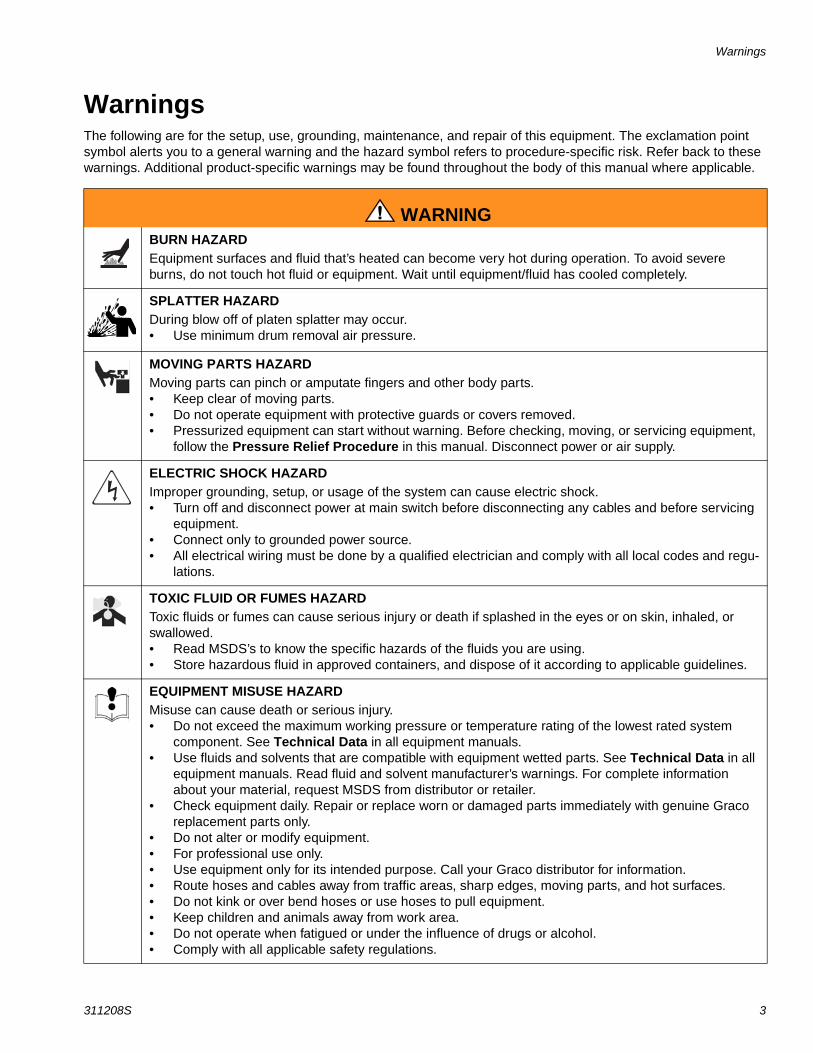
WarningsThe following are for the setup, use, grounding, maintenance, and repair of this equipment. The exclamation point symbol alerts you to a general warning and the hazard symbol refers to procedure-specific risk. Refer back to these warnings. Additional product-specific warnings may be found throughout the body of this manual where applicable.
WARNINGBURN HAZARD Equipment surfaces and fluid that’s heated can become very hot during operation. To avoid severe burns, do not touch hot fluid or equipment. Wait until equipment/fluid has cooled completely.
SPLATTER HAZARDDuring blow off of platen splatter may occur.• Use minimum drum removal air pressure.
MOVING PARTS HAZARD Moving parts can pinch or amputate fingers and other body parts.• Keep clear of moving parts.• Do not operate equipment with protective guards or covers removed.• Pressurized equipment can start without warning. Before checking, moving, or servicing equipment,
follow the Pressure Relief Procedure in this manual. Disconnect power or air supply.
ELECTRIC SHOCK HAZARD Improper grounding, setup, or usage of the system can cause electric shock.• Turn off and disconnect power at main switch before disconnecting any cables and before servicing
equipment.• Connect only to grounded power source.• All electrical wiring must be done by a qualified electrician and comply with all local codes and regu-
lations.
TOXIC FLUID OR FUMES HAZARD Toxic fluids or fumes can cause serious injury or death if splashed in the eyes or on skin, inhaled, or swallowed.• Read MSDS’s to know the specific hazards of the fluids you are using.• Store hazardous fluid in approved containers, and dispose of it according to applicable guidelines.
EQUIPMENT MISUSE HAZARD Misuse can cause death or serious injury.• Do not exceed the maximum working pressure or temperature rating of the lowest rated system
component. See Technical Data in all equipment manuals.• Use fluids and solvents that are compatible with equipment wetted parts. See Technical Data in all
equipment manuals. Read fluid and solvent manufacturer’s warnings. For complete information about your material, request MSDS from distributor or retailer.
• Check equipment daily. Repair or replace worn or damaged parts immediately with genuine Graco replacement parts only.
• Do not alter or modify equipment.• For professional use only.• Use equipment only for its intended purpose. Call your Graco distributor for information.• Route hoses and cables away from traffic areas, sharp edges, moving parts, and hot surfaces.• Do not kink or over bend hoses or use hoses to pull equipment.• Keep children and animals away from work area.• Do not operate when fatigued or under the influence of drugs or alcohol.• Comply with all applicable safety regulations.
Warnings
4 311208S
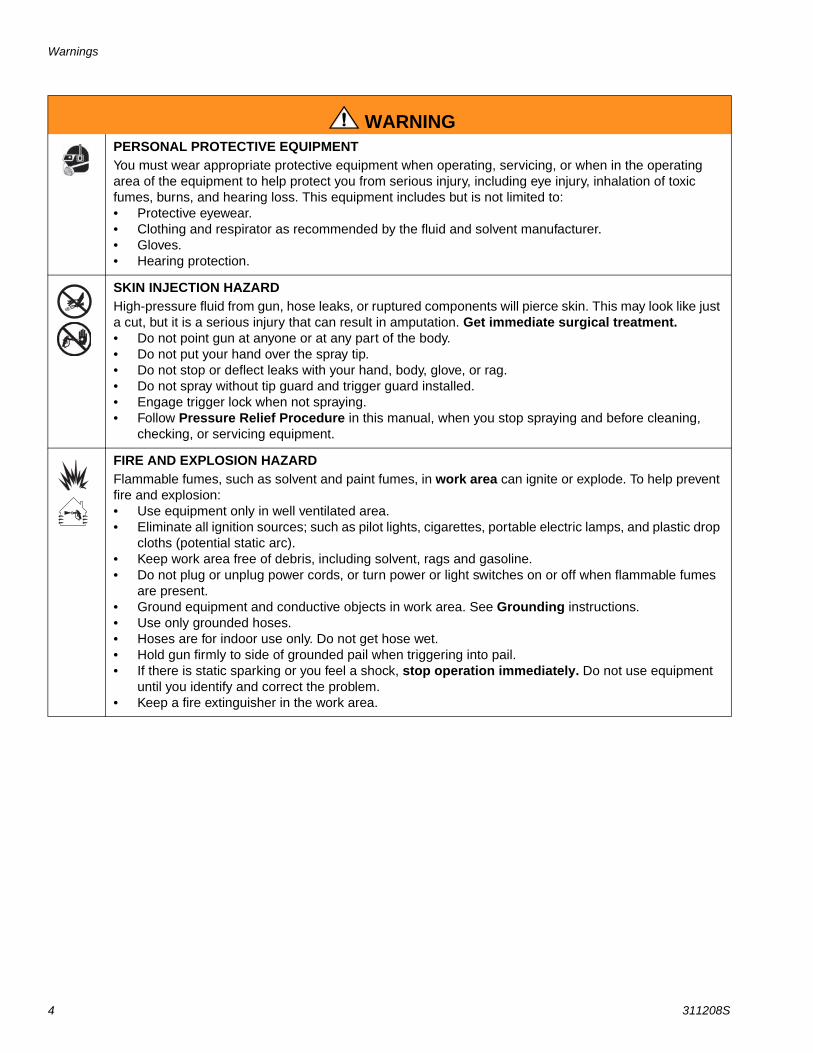
PERSONAL PROTECTIVE EQUIPMENT You must wear appropriate protective equipment when operating, servicing, or when in the operating area of the equipment to help protect you from serious injury, including eye injury, inhalation of toxic fumes, burns, and hearing loss. This equipment includes but is not limited to:• Protective eyewear.• Clothing and respirator as recommended by the fluid and solvent manufacturer.• Gloves.• Hearing protection.
SKIN INJECTION HAZARD High-pressure fluid from gun, hose leaks, or ruptured components will pierce skin. This may look like just a cut, but it is a serious injury that can result in amputation. Get immediate surgical treatment.• Do not point gun at anyone or at any part of the body.• Do not put your hand over the spray tip.• Do not stop or deflect leaks with your hand, body, glove, or rag.• Do not spray without tip guard and trigger guard installed.• Engage trigger lock when not spraying.• Follow Pressure Relief Procedure in this manual, when you stop spraying and before cleaning,
checking, or servicing equipment.
FIRE AND EXPLOSION HAZARD Flammable fumes, such as solvent and paint fumes, in work area can ignite or explode. To help prevent fire and explosion:• Use equipment only in well ventilated area.• Eliminate all ignition sources; such as pilot lights, cigarettes, portable electric lamps, and plastic drop
cloths (potential static arc). • Keep work area free of debris, including solvent, rags and gasoline.• Do not plug or unplug power cords, or turn power or light switches on or off when flammable fumes
are present.• Ground equipment and conductive objects in work area. See Grounding instructions.• Use only grounded hoses.• Hoses are for indoor use only. Do not get hose wet.• Hold gun firmly to side of grounded pail when triggering into pail.• If there is static sparking or you feel a shock, stop operation immediately. Do not use equipment
until you identify and correct the problem.• Keep a fire extinguisher in the work area.
WARNING

Warnings
311208S 5

Overview
6 311208S
OverviewHow the Therm-O-Flow 200 WorksA heated platen melts the sealant or adhesive and directs the molten material to the pump inlet. The mate-rial then travels through a heated Check–Mate pump and heated fluid moves to the application tool.
Model NumbersThis manual refers to the typical model number listed below when defining parts in your application. The model number stamped on your machine defines the equipment in the following 10 categories:
1. Motor2. Heated Platen3. Follower Seals4. Drum Ram5. Number of Heat Zones6. Heat Controls Supply Voltage7. Control Panel8. Drum Unloader Options9. Application Accessories10. Hose Kit Layout
Typical Model Number: TOF200A–D–1–A–1–P–6–2–A–F–1–N–1–1–D–P–N-NModel Product Description
TOF200A 55 gal./200 liter Hot Melt Drum Unloader
Code A Air Motor Selection1 NXT 2200 HLS quiet air motor (23:1 Power Ratio)
with pump
2 NXT 3400 HLS quiet air motor (36:1 Power Ratio) with pump
3 NXT 6500 HLS quiet air motor (70:1 Power Ratio) with pump
N No air motor or pump
4 NXT 2200 HLS quiet air motor (23:1 Power Ratio) with pump and heavy duty packings
5 NXT 3400 HLS quiet air motor (36:1 Power Ratio) with pump and heavy duty packings
6 NXT 6500 HLS quiet air motor (70:1 Power Ratio) with pump and heavy duty packings
Code B Heated Platen StyleA Mega-Flo™ high flow drum platen
B Standard fin design drum platen
C Smooth bottom (no fin) drum platen
Code C Tire Plate Seal Style1 2 Black EPDM/EPDM, SS wire braid 400oF hose
wipers w/spring retention
2 1 lower Black EPDM/Chlorobutyl, SS wire braid 375oF hose wiper and 1 upper White Silicone 375oF T-wiper
3 1 lower Black EPDM/Chlorobutyl, SS wire braid 400oF hose wiper and 1 upper Green Silicone, fiberglass braid 400oF, hose wiper
4 2 White Silicone 250oF T-Wipers
Code D Drum Ram StyleP Pneumatic Ram
H Hydraulic Ram
Code E Number of Heat Zones6 6 Zones
8 8 Zones
N No electrical control panel (includes pneumatic controls, independently mounted)
If Code E option N is selected, then Codes F and G must also be option N and Code H is ignored.
Code F Customer’s Power Supply Voltage2 220/240 Vac 50/60 Hz 3 phase
3 380/400 Vac 50/60 Hz 3 phase
4 470/490 Vac 50/60 Hz 3 phase
5 570/590 Vac 50/60 Hz 3 phase
N No electrical control panel
Code G Display and Interface OptionsB Standard unit – uses EasyKey
A Advanced unit – EasyKey with discrete I/O, Ethernet, light tower, and proximity switches.
T Tandem primary unit – Unloader A in a primary unit.
S Tandem secondary unit – Unloader B in a tandem unit.
N No electrical control panel
Code H Language SelectionE English
F French
G German
S Spanish
J Japanese
C Chinese (Simplified)
Code J Drum Clamp Options1 Fiber drum reinforcement clam shell
2 Heavy duty drum band clamp
3 Drum ram post saddle clamps
N No drum clamp option
Code K Vent Hood KitN None
Y Vent Hood Kit
Code L Swirl Solenoid KitN None
1 Single Swirl Solenoid Kit
2 Dual Swirl Solenoid Kit
Overview
311208S 7
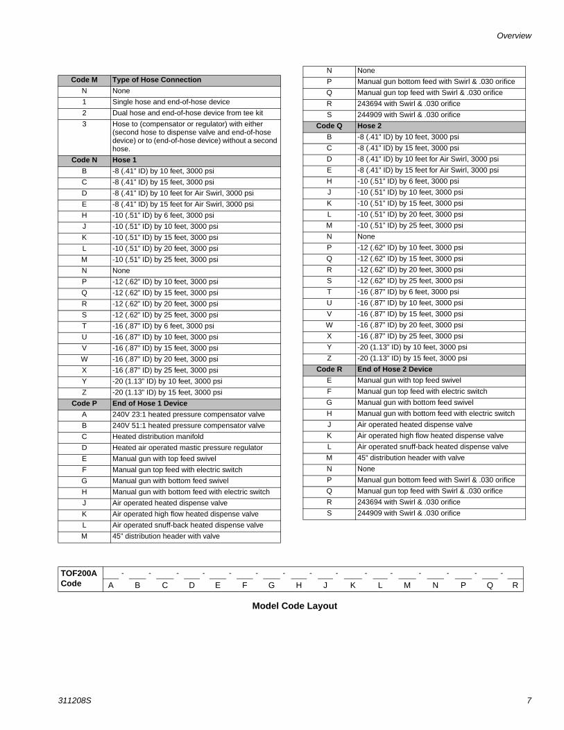
Model Code Layout
Code M Type of Hose ConnectionN None
1 Single hose and end-of-hose device
2 Dual hose and end-of-hose device from tee kit
3 Hose to (compensator or regulator) with either (second hose to dispense valve and end-of-hose device) or to (end-of-hose device) without a second hose.
Code N Hose 1B -8 (.41” ID) by 10 feet, 3000 psi
C -8 (.41” ID) by 15 feet, 3000 psi
D -8 (.41” ID) by 10 feet for Air Swirl, 3000 psi
E -8 (.41” ID) by 15 feet for Air Swirl, 3000 psi
H -10 (.51” ID) by 6 feet, 3000 psi
J -10 (.51” ID) by 10 feet, 3000 psi
K -10 (.51” ID) by 15 feet, 3000 psi
L -10 (.51” ID) by 20 feet, 3000 psi
M -10 (.51” ID) by 25 feet, 3000 psi
N None
P -12 (.62” ID) by 10 feet, 3000 psi
Q -12 (.62” ID) by 15 feet, 3000 psi
R -12 (.62” ID) by 20 feet, 3000 psi
S -12 (.62” ID) by 25 feet, 3000 psi
T -16 (.87” ID) by 6 feet, 3000 psi
U -16 (.87” ID) by 10 feet, 3000 psi
V -16 (.87” ID) by 15 feet, 3000 psi
W -16 (.87” ID) by 20 feet, 3000 psi
X -16 (.87” ID) by 25 feet, 3000 psi
Y -20 (1.13” ID) by 10 feet, 3000 psi
Z -20 (1.13” ID) by 15 feet, 3000 psi
Code P End of Hose 1 DeviceA 240V 23:1 heated pressure compensator valve
B 240V 51:1 heated pressure compensator valve
C Heated distribution manifold
D Heated air operated mastic pressure regulator
E Manual gun with top feed swivel
F Manual gun top feed with electric switch
G Manual gun with bottom feed swivel
H Manual gun with bottom feed with electric switch
J Air operated heated dispense valve
K Air operated high flow heated dispense valve
L Air operated snuff-back heated dispense valve
M 45” distribution header with valve
N None
P Manual gun bottom feed with Swirl & .030 orifice
Q Manual gun top feed with Swirl & .030 orifice
R 243694 with Swirl & .030 orifice
S 244909 with Swirl & .030 orifice
Code Q Hose 2B -8 (.41” ID) by 10 feet, 3000 psi
C -8 (.41” ID) by 15 feet, 3000 psi
D -8 (.41” ID) by 10 feet for Air Swirl, 3000 psi
E -8 (.41” ID) by 15 feet for Air Swirl, 3000 psi
H -10 (.51” ID) by 6 feet, 3000 psi
J -10 (.51” ID) by 10 feet, 3000 psi
K -10 (.51” ID) by 15 feet, 3000 psi
L -10 (.51” ID) by 20 feet, 3000 psi
M -10 (.51” ID) by 25 feet, 3000 psi
N None
P -12 (.62” ID) by 10 feet, 3000 psi
Q -12 (.62” ID) by 15 feet, 3000 psi
R -12 (.62” ID) by 20 feet, 3000 psi
S -12 (.62” ID) by 25 feet, 3000 psi
T -16 (.87” ID) by 6 feet, 3000 psi
U -16 (.87” ID) by 10 feet, 3000 psi
V -16 (.87” ID) by 15 feet, 3000 psi
W -16 (.87” ID) by 20 feet, 3000 psi
X -16 (.87” ID) by 25 feet, 3000 psi
Y -20 (1.13” ID) by 10 feet, 3000 psi
Z -20 (1.13” ID) by 15 feet, 3000 psi
Code R End of Hose 2 DeviceE Manual gun with top feed swivel
F Manual gun top feed with electric switch
G Manual gun with bottom feed swivel
H Manual gun with bottom feed with electric switch
J Air operated heated dispense valve
K Air operated high flow heated dispense valve
L Air operated snuff-back heated dispense valve
M 45” distribution header with valve
N None
P Manual gun bottom feed with Swirl & .030 orifice
Q Manual gun top feed with Swirl & .030 orifice
R 243694 with Swirl & .030 orifice
S 244909 with Swirl & .030 orifice
TOF200ACode
- - - - - - - - - - - - - - -
A B C D E F G H J K L M N P Q R
Overview
8 311208S
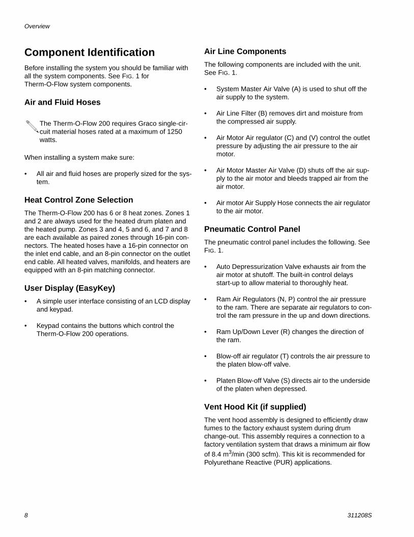
Component IdentificationBefore installing the system you should be familiar with all the system components. See FIG. 1 for Therm-O-Flow system components.
Air and Fluid Hoses
When installing a system make sure:
• All air and fluid hoses are properly sized for the sys-tem.
Heat Control Zone Selection The Therm-O-Flow 200 has 6 or 8 heat zones. Zones 1 and 2 are always used for the heated drum platen and the heated pump. Zones 3 and 4, 5 and 6, and 7 and 8 are each available as paired zones through 16-pin con-nectors. The heated hoses have a 16-pin connector on the inlet end cable, and an 8-pin connector on the outlet end cable. All heated valves, manifolds, and heaters are equipped with an 8-pin matching connector.
User Display (EasyKey)• A simple user interface consisting of an LCD display
and keypad.
• Keypad contains the buttons which control the Therm-O-Flow 200 operations.
Air Line ComponentsThe following components are included with the unit. See FIG. 1.
• System Master Air Valve (A) is used to shut off the air supply to the system.
• Air Line Filter (B) removes dirt and moisture from the compressed air supply.
• Air Motor Air regulator (C) and (V) control the outlet pressure by adjusting the air pressure to the air motor.
• Air Motor Master Air Valve (D) shuts off the air sup-ply to the air motor and bleeds trapped air from the air motor.
• Air motor Air Supply Hose connects the air regulator to the air motor.
Pneumatic Control PanelThe pneumatic control panel includes the following. See FIG. 1.
• Auto Depressurization Valve exhausts air from the air motor at shutoff. The built-in control delays start-up to allow material to thoroughly heat.
• Ram Air Regulators (N, P) control the air pressure to the ram. There are separate air regulators to con-trol the ram pressure in the up and down directions.
• Ram Up/Down Lever (R) changes the direction of the ram.
• Blow-off air regulator (T) controls the air pressure to the platen blow-off valve.
• Platen Blow-off Valve (S) directs air to the underside of the platen when depressed.
Vent Hood Kit (if supplied) The vent hood assembly is designed to efficiently draw fumes to the factory exhaust system during drum change-out. This assembly requires a connection to a factory ventilation system that draws a minimum air flow
of 8.4 m3/min (300 scfm). This kit is recommended for Polyurethane Reactive (PUR) applications.
The Therm-O-Flow 200 requires Graco single-cir-cuit material hoses rated at a maximum of 1250 watts.
Overview
311208S 9
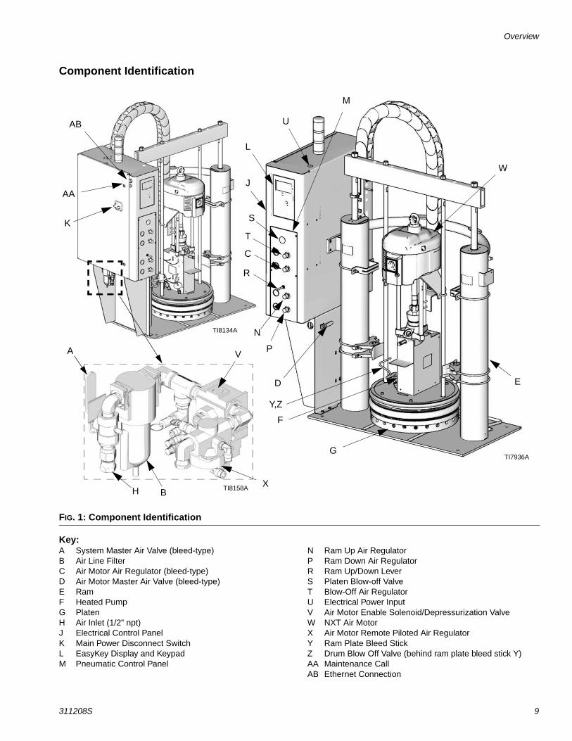
Component Identification
Key:A System Master Air Valve (bleed-type)B Air Line FilterC Air Motor Air Regulator (bleed-type)D Air Motor Master Air Valve (bleed-type)E RamF Heated PumpG PlatenH Air Inlet (1/2” npt)J Electrical Control PanelK Main Power Disconnect SwitchL EasyKey Display and KeypadM Pneumatic Control Panel
N Ram Up Air RegulatorP Ram Down Air RegulatorR Ram Up/Down LeverS Platen Blow-off ValveT Blow-Off Air RegulatorU Electrical Power InputV Air Motor Enable Solenoid/Depressurization ValveW NXT Air MotorX Air Motor Remote Piloted Air RegulatorY Ram Plate Bleed StickZ Drum Blow Off Valve (behind ram plate bleed stick Y)AA Maintenance CallAB Ethernet Connection
FIG. 1: Component Identification
VA
B
K
U
W
E
G
F
Y,Z
D
P
N
R
C
T
S
J
L
HX
AB
AA
M
TI8134A
TI7936A
TI8158A

Typical Installation
10 311208S
Typical InstallationThe typical installation discussed and shown is only a guide for selecting and installing system components and accessories. See FIG. 2. Contact your Graco distrib-utor for help in designing a system to suit your particular needs.
The air-powered ram extruder forces high viscosity flu-ids into the intake valve of the fluid pump. Wiper rings and other accessory equipment for use with this ram are listed in Technical Data on page 97.
Power RequirementsSee Technical Data on page 97.
Selecting a Location for the RamRefer to the Dimensions drawing on page 96 for ram mounting and clearance dimensions.
When selecting a location for the ram keep the following in mind:
1. There should be sufficient space for installing and using the equipment.
• Make sure there is sufficient overhead clear-ance for the pump and ram when the ram is in the fully raised position.
• If you are installing a vent hood make sure there is sufficient horizontal clearance for it.
• Make sure the air regulators for the pump and ram are fully accessible.
• Make sure there is easy access to an appropri-ate electrical power source. The National Elec-trical Code requires 3 feet of open space in front of the electrical panel.
2. Make sure that you will be able to level the base of the ram using metal shims.
3. When you bolt the ram to the floor the anchors should be long enough to prevent the unit from tip-ping. Refer to the Dimensions drawing on page 96 for more information.
4. If you are installing a vent hood, make sure the ram is installed near a connection to the factory ventila-tion system.
System Accessories and ModulesBefore you install the system you should be familiar with all the parts and system requirements for the Therm-O-Flow 200.
For information about converting the ram from air to hydraulic operation, contact your Graco distributor.
Typical Installation
311208S 11
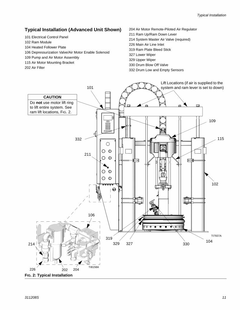
Typical Installation (Advanced Unit Shown)101 Electrical Control Panel
102 Ram Module104 Heated Follower Plate
106 Depressurization Valve/Air Motor Enable Solenoid
109 Pump and Air Motor Assembly
115 Air Motor Mounting Bracket202 Air Filter
204 Air Motor Remote-Piloted Air Regulator211 Ram Up/Ram Down Lever
214 System Master Air Valve (required)
226 Main Air Line Inlet319 Ram Plate Bleed Stick
327 Lower Wiper
329 Upper Wiper
330 Drum Blow Off Valve332 Drum Low and Empty Sensors
FIG. 2: Typical Installation
101
102
104
109
115
211
319329 327
226 202 204
Lift Locations (if air is supplied to the system and ram lever is set to down)
214
106
CAUTIONDo not use motor lift ring to lift entire system. See ram lift locations, FIG. 2.
330
332
TI7937A
TI8158A

Typical Installation
12 311208S
Heat Control Zone SelectionThe Therm–O–Flow 200 can be ordered with 6 (code E–6) or 8 (code E–8) heat zones (see Fig.3). Zones 1 and 2 are always used for the heated drum platen and the heated pump. Zones 3 and 4, 5 and 6, and optional zones 7 and 8 are each available as paired zones through a 16–pin connector.
The heated hoses have a 16–pin connector on the inlet end cable, and an 8–pin connector on the outlet end cable. All heated valves, manifolds and heaters are equipped with an 8–pin matching connector. Accessory cables are available for other possible combinations. See FIG. 3.
Air Line Modules
4-Regulator Air Control Module (shown)For more information, refer to FIG. 1 on page 9. The fol-lowing components are included with the module:
• System Master Air Valve (bleed-type) (D) is used to shut off the air supply to the entire supply unit.
• Air Motor Master Air Valve (bleed-type) (D) is sup-plied in your system to relieve air trapped between it and the air motor when the valve is energized (see Warning above). This bleed valve should be easily accessible and located downstream from the air regulator.
• Air Motor Air Regulator (C) controls the pump outlet pressure by adjusting the air pressure to the air motor. It is located on the pneumatic control panel.
• The Air Motor Enable Solenoid, see FIG. 1 page 9, letter (X) delays startup to allow material to heat thoroughly.
• Ram Air Regulator (N,P) controls the air pressure to the ram. There are separate air regulators to control the ram pressure in the up and down directions.
• Ram Plate Blow-off Valve (S,T) controls the air to the ram plate blow-off.
Fluid Line Accessories (Typical)A pressure compensator valve controls fluid pressure to the gun/valve, and dampens pressure surges. Install the pressure compensator valve using adapters as neces-sary.
FIG. 3: Heat Control Zone Selection
The Air Motor bleed-type master air valve (D) is required in your system to relieve motor air pressure. Trapped air can cause the pump to cycle unexpect-edly, which can result in serious bodily injury.
Part No. 297401 is used if “None” is selected for Configurator Code E, F, and G.
Installation Procedure
311208S 13
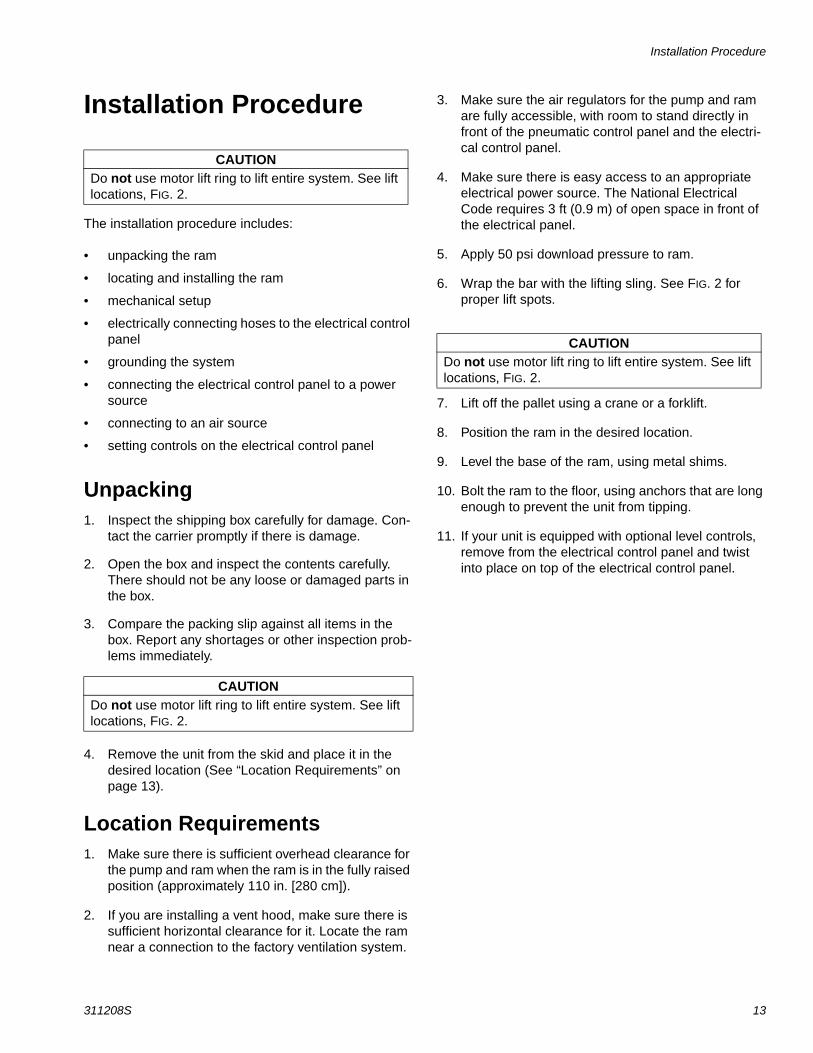
Installation Procedure
The installation procedure includes:
• unpacking the ram
• locating and installing the ram
• mechanical setup
• electrically connecting hoses to the electrical control panel
• grounding the system
• connecting the electrical control panel to a power source
• connecting to an air source
• setting controls on the electrical control panel
Unpacking1. Inspect the shipping box carefully for damage. Con-
tact the carrier promptly if there is damage.
2. Open the box and inspect the contents carefully. There should not be any loose or damaged parts in the box.
3. Compare the packing slip against all items in the box. Report any shortages or other inspection prob-lems immediately.
4. Remove the unit from the skid and place it in the desired location (See “Location Requirements” on page 13).
Location Requirements1. Make sure there is sufficient overhead clearance for
the pump and ram when the ram is in the fully raised position (approximately 110 in. [280 cm]).
2. If you are installing a vent hood, make sure there is sufficient horizontal clearance for it. Locate the ram near a connection to the factory ventilation system.
3. Make sure the air regulators for the pump and ram are fully accessible, with room to stand directly in front of the pneumatic control panel and the electri-cal control panel.
4. Make sure there is easy access to an appropriate electrical power source. The National Electrical Code requires 3 ft (0.9 m) of open space in front of the electrical panel.
5. Apply 50 psi download pressure to ram.
6. Wrap the bar with the lifting sling. See FIG. 2 for proper lift spots.
7. Lift off the pallet using a crane or a forklift.
8. Position the ram in the desired location.
9. Level the base of the ram, using metal shims.
10. Bolt the ram to the floor, using anchors that are long enough to prevent the unit from tipping.
11. If your unit is equipped with optional level controls, remove from the electrical control panel and twist into place on top of the electrical control panel.
CAUTIONDo not use motor lift ring to lift entire system. See lift locations, FIG. 2.
CAUTIONDo not use motor lift ring to lift entire system. See lift locations, FIG. 2.
CAUTIONDo not use motor lift ring to lift entire system. See lift locations, FIG. 2.
Installation Procedure
14 311208S
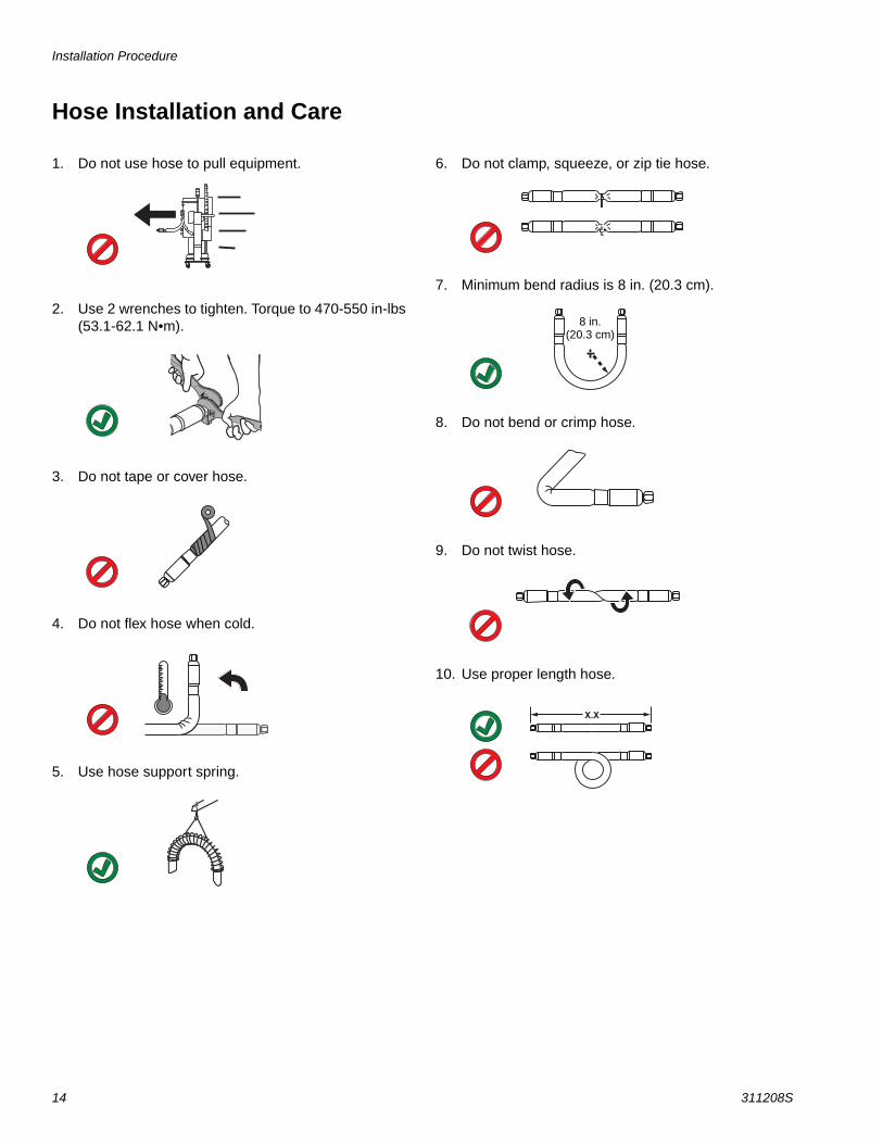
Hose Installation and Care
1. Do not use hose to pull equipment.
2. Use 2 wrenches to tighten. Torque to 470-550 in-lbs (53.1-62.1 N•m).
3. Do not tape or cover hose.
4. Do not flex hose when cold.
5. Use hose support spring.
6. Do not clamp, squeeze, or zip tie hose.
7. Minimum bend radius is 8 in. (20.3 cm).
8. Do not bend or crimp hose.
9. Do not twist hose.
10. Use proper length hose.
8 in.(20.3 cm)
Installation Procedure
311208S 15
Mechanical Setup1. Check, and if necessary, tighten the heated hose
connection at the pump outlet.
2. Wrap exposed fittings on the pump outlet with Nomex insulation and secure insulation using fiber-glass tape.
3. Fill displacement pump wet cup 2/3 full with Graco Throat Seal Liquid (TSL).
4. Back-off all air regulators to their full counterclock-wise position.
5. Connect a 1/2 in. (13 mm) air line from an air source to the system air inlet, see FIG. 1, page 9, letter (H) capable of delivering a minimum of 15 cfm (0.4
m3/m) at 100 psi (0.7 MPa, 7.0 bar). Do not use quick disconnects.
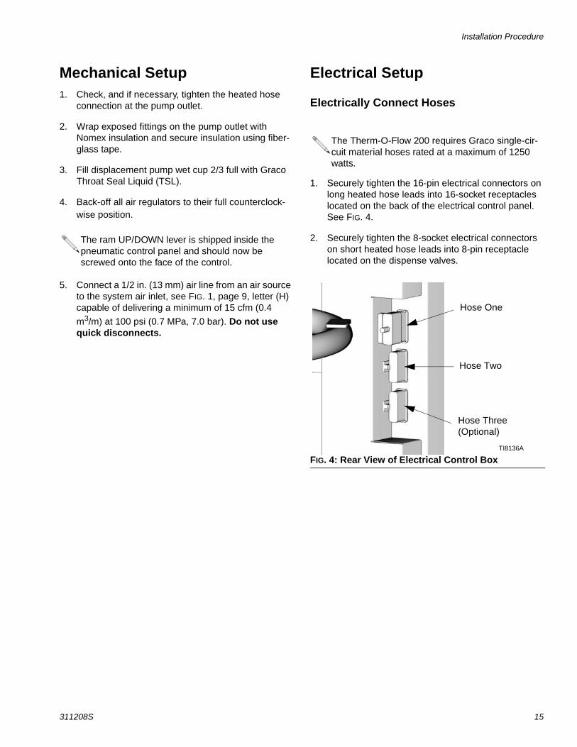
Electrical Setup
Electrically Connect Hoses
1. Securely tighten the 16-pin electrical connectors on long heated hose leads into 16-socket receptacles located on the back of the electrical control panel. See FIG. 4.
2. Securely tighten the 8-socket electrical connectors on short heated hose leads into 8-pin receptacle located on the dispense valves.
The ram UP/DOWN lever is shipped inside the pneumatic control panel and should now be screwed onto the face of the control.
The Therm-O-Flow 200 requires Graco single-cir-cuit material hoses rated at a maximum of 1250 watts.
FIG. 4: Rear View of Electrical Control Box
Hose One
Hose Two
Hose Three(Optional)
TI8136A
Installation Procedure
16 311208S
Connect Power SourceThe electrical control panel comes already attached and wired to the ram, however before the supply unit becomes functional you must connect the electrical con-trol panel to a power source.
1. Open electrical enclosure door and locate the main disconnect.
2. Have a qualified electrician connect your plant power to the electrical control panel disconnect switch according to local codes. A 1-3/8 in. (35 mm) diameter opening is provided on top of the panel above the connections. This opening is suitable for a 1 in. npt conduit or strain relief fitting.
BB = Standard grid platen: 18 Kw
BA = Mega-Flo™ platen: 21 KwBC = Smooth bottom platen: 18 Kw
GroundingGround the supply unit as instructed here and in the individual component manuals.
To reduce the risk of static sparking, ground the pump, the object being dispensed to, and all other spraying/dis-pensing equipment used or located in the spraying/dis-pensing area. Check your local electrical code for detailed grounding instructions for your area and type of equipment.
• Air and fluid hoses: Use only electrically conductive hoses.
• Dispensing/Spray Gun: Follow the dispensing/spray gun grounding instructions.
• Object material is applied to: Ground according to your local code.
• Material drums: Ground according to your local code. Use only metal drums placed on a grounded surface. Do not place the drum on a nonconductive surface, such as paper or cardboard, which inter-rupts the grounding continuity.
• Maintain grounding continuity when flushing or relieving pressure: Follow the instructions in your separate gun manual for safely grounding your gun while flushing.
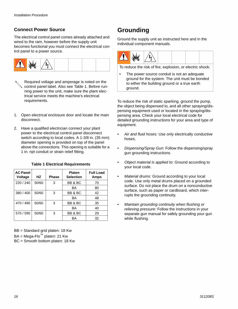
Required voltage and amperage is noted on the control panel label. Also see Table 1. Before run-ning power to the unit, make sure the plant elec-trical service meets the machine’s electrical requirements.
Table 1 Electrical Requirements
AC Panel Voltage HZ Phase
Platen Selection
Full Load Amps
220 / 240 50/60 3 BB & BC 70
BA 80380 / 400 50/60 3 BB & BC 42
BA 48
470 / 490 50/60 3 BB & BC 35BA 40
570 / 590 50/60 3 BB & BC 29
BA 32
To reduce the risk of fire, explosion, or electric shock:
• The power source conduit is not an adequate ground for the system. The unit must be bonded to either the building ground or a true earth ground.

Installation Procedure
311208S 17
Connecting the Electrical Control Panel to a Power SourceThe electrical control panel (FIG. 5) comes already attached and wired to the ram, however before the sup-ply unit becomes functional, you must connect the elec-trical control panel to a power source.
Have a trained electrician connect the electrical control panel (Fig. 5) to a grounded electrical source that has the required service ratings, see Electrical Require-ments on page 16.
BB = Standard grid platen: 18 Kw
BA = Mega–Flo platen: 21 Kw
BC = Smooth bottom platen: 18 Kw
For information about specific terminal locations and connections, see Advanced Units on page 80.
To connect the control panel to the electrical source:
1. Locate the opening in the control panel’s top hous-ing for the conduit that will enclose the wire from the facility’s power source. The hole will accept a 1” conduit fitting. It is 1.3” dia. (33mm).
2. Thread the wire from the power source into the con-trol panel housing, and then connect the power source wires to the appropriate terminals on the DISCONNECT switch.
FIG. 5: Electrical Control Panel
CAUTIONIf power and grounding connections are not done properly, the equipment will be damaged and the war-ranty will be voided. Check the label on the control box for the proper voltage.
ElectricalControlPanel
TI7935A
Installation Procedure
18 311208S
Check the Resistance Between the Supply Unit and the True Earth Ground.
Have a qualified electrician check the resistance between each supply unit component and the true earth ground. The resistance must be less than 0.25 ohms. If the resistance is greater than 0.25 ohms a different ground site may be required. Do not operate the system until the problem is corrected.
Checking Resistance.
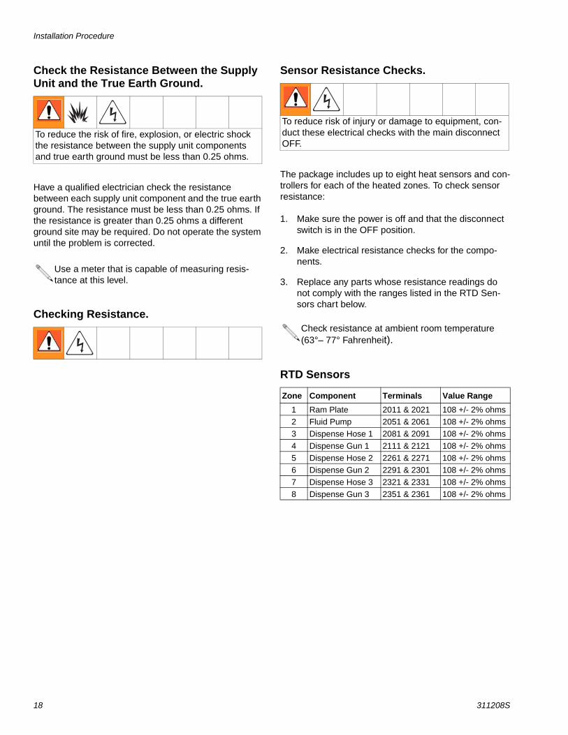
Sensor Resistance Checks.
The package includes up to eight heat sensors and con-trollers for each of the heated zones. To check sensor resistance:
1. Make sure the power is off and that the disconnect switch is in the OFF position.
2. Make electrical resistance checks for the compo-nents.
3. Replace any parts whose resistance readings do not comply with the ranges listed in the RTD Sen-sors chart below.
RTD Sensors
To reduce the risk of fire, explosion, or electric shock the resistance between the supply unit components and true earth ground must be less than 0.25 ohms.
Use a meter that is capable of measuring resis-tance at this level.
To reduce risk of injury or damage to equipment, con-duct these electrical checks with the main disconnect OFF.
Check resistance at ambient room temperature (63°– 77° Fahrenheit).
Zone Component Terminals Value Range
1 Ram Plate 2011 & 2021 108 +/- 2% ohms
2 Fluid Pump 2051 & 2061 108 +/- 2% ohms3 Dispense Hose 1 2081 & 2091 108 +/- 2% ohms
4 Dispense Gun 1 2111 & 2121 108 +/- 2% ohms
5 Dispense Hose 2 2261 & 2271 108 +/- 2% ohms6 Dispense Gun 2 2291 & 2301 108 +/- 2% ohms
7 Dispense Hose 3 2321 & 2331 108 +/- 2% ohms
8 Dispense Gun 3 2351 & 2361 108 +/- 2% ohms
Installation Procedure
311208S 19
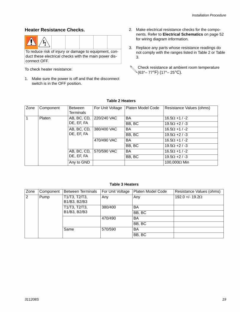
Heater Resistance Checks.
To check heater resistance:
1. Make sure the power is off and that the disconnect switch is in the OFF position.
2. Make electrical resistance checks for the compo-nents. Refer to Electrical Schematics on page 52 for wiring diagram information.
3. Replace any parts whose resistance readings do not comply with the ranges listed in Table 2 or Table 3.
To reduce risk of injury or damage to equipment, con-duct these electrical checks with the main power dis-connect OFF.
Check resistance at ambient room temperature (63°– 77°F) (17°– 25°C).
Table 2 Heaters
Zone Component Between Terminals
For Unit Voltage Platen Model Code Resistance Values (ohms)
1 Platen AB, BC, CD, DE, EF, FA
220/240 VAC BA 16.5 +1 / -2BB, BC 19.5 +2 / -3
AB, BC, CD, DE, EF, FA
380/400 VAC BA 16.5 +1 / -2BB, BC 19.5 +2 / -3
470/490 VAC BA 16.5 +1 / -2BB, BC 19.5 +2 / -3
AB, BC, CD, DE, EF, FA
570/590 VAC BA 16.5 +1 / -2BB, BC 19.5 +2 / -3
Any to GND 100,000Min
Table 3 Heaters
Zone Component Between Terminals For Unit Voltage Platen Model Code Resistance Values (ohms)2 Pump T1/T3, T2/T3,
B1/B3, B2/B3Any Any 192.0 +/- 19.2
T1/T3, T2/T3, B1/B3, B2/B3
380/400 BABB, BC
470/490 BABB, BC
Same 570/590 BABB, BC
Installation Procedure
20 311208S
Overview of the Temperature Controller SettingsTemperature controls are set in the zone configuration setup screens. See Run Screens on page 23 for infor-mation about setting temperature controls.
P, I, and D settings are preset for device types and will not need to be changed. Refer to the Zone Setup Screens on page 24 for a list of device types and how to set them for each zone.
Purging the SystemPurging the system before the initial use can prevent material contamination, which may cause the material to fail or perform poorly.
To purge the system perform the following procedure:
1. Select the material for the initial material load.
2. Verify whether the factory-test oil and the initial material load are compatible:
a. If the two substances are compatible omit the remaining steps in this procedure and refer to the start up and operation instructions.
b. If the two substances are incompatible perform the remaining steps in this procedure to flush the system.
3. Select a drum of material that can eliminate the fac-tory-test oil from the system. If necessary, check with Graco or the material supplier for a recom-mended solvent.
4. Before purging be sure the entire system and waste drum are properly grounded. Refer to Grounding on page 16.
5. Turn all heat zones to 70°F (21.1°C). This allows air to the air motor, with no alarms, in a cold state.
6. Purge the material through the system for approxi-mately 1 to 2 minutes.
7. Remove the drum if purge material was used.
CAUTIONPurge the system before performing the initial material loading procedure. The system was factory- tested using a light soluble oil, a soybean oil, or some other oil as tagged. Flush the system to avoid contaminating the material that has been designated for initial mate-rial loading.
Use fluids that are chemically compatible with the equipment wetted parts. See the Technical Data sec-tions of all the equipment manuals.
This equipment should not be used with more than one type of fluid due to potential compatibility issues which could result in an unpredictable reaction. Graco recom-mends using new hoses when chemicals are changed or care must be taken to assure that all traces of one chemical are removed before introducing a second chemical.
Remove any dispense valve orifices before purg-ing. Reinstall after purging has been completed.
Operator Controls
311208S 21
Operator Controls
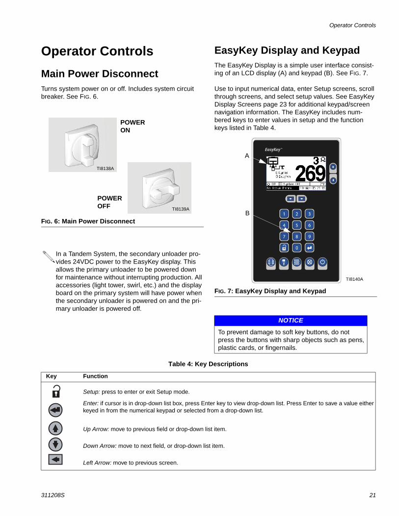
Main Power DisconnectTurns system power on or off. Includes system circuit breaker. See FIG. 6.
EasyKey Display and KeypadThe EasyKey Display is a simple user interface consist-ing of an LCD display (A) and keypad (B). See FIG. 7.
Use to input numerical data, enter Setup screens, scroll through screens, and select setup values. See EasyKey Display Screens page 23 for additional keypad/screen navigation information. The EasyKey includes num-bered keys to enter values in setup and the function keys listed in Table 4.
FIG. 6: Main Power Disconnect
In a Tandem System, the secondary unloader pro-vides 24VDC power to the EasyKey display. This allows the primary unloader to be powered down for maintenance without interrupting production. All accessories (light tower, swirl, etc.) and the display board on the primary system will have power when the secondary unloader is powered on and the pri-mary unloader is powered off.
POWER OFF
POWER ON
TI8138A
TI8139A
FIG. 7: EasyKey Display and Keypad
NOTICE
To prevent damage to soft key buttons, do not press the buttons with sharp objects such as pens, plastic cards, or fingernails.
A
B
TI8140A
Table 4: Key Descriptions
Key Function
Setup: press to enter or exit Setup mode.
Enter: if cursor is in drop-down list box, press Enter key to view drop-down list. Press Enter to save a value either keyed in from the numerical keypad or selected from a drop-down list.
Up Arrow: move to previous field or drop-down list item.
Down Arrow: move to next field, or drop-down list item.
Left Arrow: move to previous screen.
Operator Controls
22 311208S
LCD DisplayThe two run screens show graphical and text informa-tion related to setup and spray operations.
A screen saver option is available in the Advanced Setup screen 4 (see Table 7, page 28).
A Animation: when there is flow the air motor piston and pump displacement rod move and the gun appears to spray.
B Total Job Volume: recorded in units selected in Table 7, see page 28. Press twice to reset Total Job Volume to zero.
C Current Flow Rate: flow rate displayed in units selected in Adv tab of setup. See Table 7 on page 28.
D Zone Number and Icon: shows which zone data is currently being displayed. Icon indicates component for that zone.
E Temperature Readout: shows current temperature of each zone, in temperature units selected in Table 7, see page 28.
F Status Bar: shows current operation mode or alarm.
G Current Date and Time
H Security Level: a padlock appears on the screen if a password is required to enter Setup mode. If the password was set to 0, no padlock appears and setup can be entered without a password.
AlarmAlerts the user to an alarm condition. Press to clear the alarm.
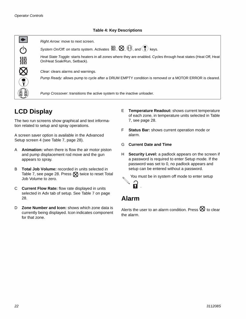
Right Arrow: move to next screen.
System On/Off: on starts system. Activates , , , and keys.
Heat State Toggle: starts heaters in all zones where they are enabled. Cycles through heat states (Heat Off, Heat On/Heat Soak/Run, Setback).
Clear: clears alarms and warnings.
Pump Ready: allows pump to cycle after a DRUM EMPTY condition is removed or a MOTOR ERROR is cleared.
Pump Crossover: transitions the active system to the inactive unloader.
Table 4: Key Descriptions
You must be in system off mode to enter setup
.

EasyKey Display Screens
311208S 23
EasyKey Display Screens
Power Up ScreensWhen the EasyKey power switch is turned on the Graco logo screen and the phrase establishing communication displays for several seconds before the system run screen appears.
If the EasyKey cannot communicate with any board during the power on phase, the phrase “Communication Error” displays on the Graco Logo screen. Once com-munications are established the System Run Screen appears. See FIG. 9.
Run screens and setup screens are the two main screen types that provide information and system control.
Run ModeRun Screens
System Run Screen
From the Zone Run screen, press or to access the System Run screen. This screen displays a summary of all zones. See FIG. 8.
Zone Run Screen
This screen contains all specific zone information for each zone in the system. Tandem and expansion sys-tems will contain two zone run screens A and B, one for each set of 4,6, or 8 zones. The Zone Run screen steps through the operating status of each zone in sequence. See FIG. 9.
FIG. 8: System Run Screen
Temperature setpoints are adjustable on this screen if Setpoint Adjust is turned on. See Advanced Screens, page 27. Setpoints will be
highlighted in a box. Use the or keys to move through the setpoints.
FIG. 9: Zone A Run Screen
FIG. 10: Zone B Run Screen
EasyKey Display Screens
24 311208S
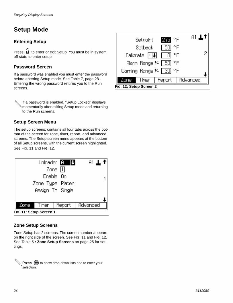
Setup Mode
Entering Setup
Press to enter or exit Setup. You must be in system off state to enter setup.
Password ScreenIf a password was enabled you must enter the password before entering Setup mode. See Table 7, page 28. Entering the wrong password returns you to the Run screens.
Setup Screen MenuThe setup screens, contains all four tabs across the bot-tom of the screen for zone, timer, report, and advanced screens. The Setup screen menu appears at the bottom of all Setup screens, with the current screen highlighted. See FIG. 11 and FIG. 12.
Zone Setup ScreensZone Setup has 2 screens. The screen number appears on the right side of the screen. See FIG. 11 and FIG. 12. See Table 5 : Zone Setup Screens on page 25 for set-tings.
If a password is enabled, “Setup Locked” displays momentarily after exiting Setup mode and returning to the Run screens.
FIG. 11: Setup Screen 1
Press to show drop-down lists and to enter your selection.
FIG. 12: Setup Screen 2
EasyKey Display Screens
311208S 25
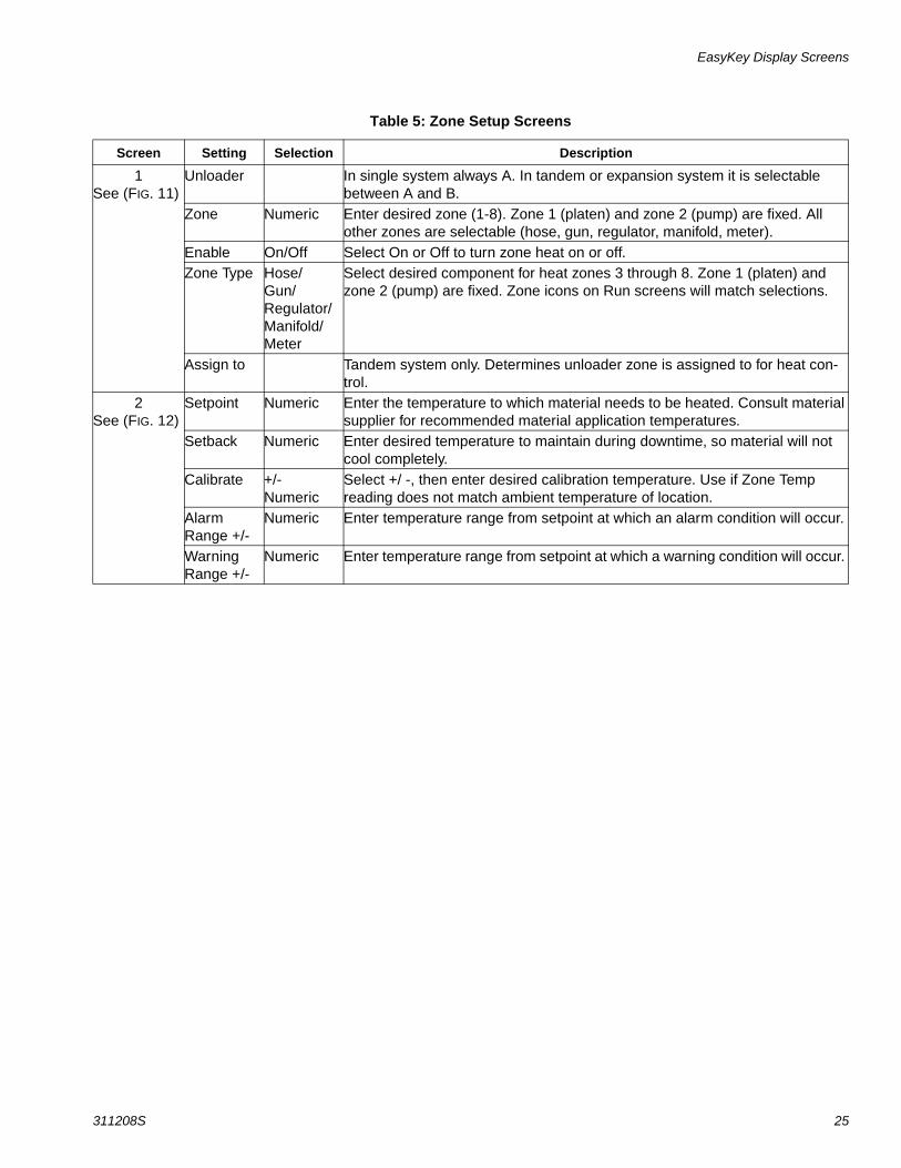
Table 5: Zone Setup Screens
Screen Setting Selection Description
1See (FIG. 11)
Unloader In single system always A. In tandem or expansion system it is selectable between A and B.
Zone Numeric Enter desired zone (1-8). Zone 1 (platen) and zone 2 (pump) are fixed. All other zones are selectable (hose, gun, regulator, manifold, meter).
Enable On/Off Select On or Off to turn zone heat on or off.Zone Type Hose/
Gun/Regulator/Manifold/Meter
Select desired component for heat zones 3 through 8. Zone 1 (platen) and zone 2 (pump) are fixed. Zone icons on Run screens will match selections.
Assign to Tandem system only. Determines unloader zone is assigned to for heat con-trol.
2 See (FIG. 12)
Setpoint Numeric Enter the temperature to which material needs to be heated. Consult material supplier for recommended material application temperatures.
Setback Numeric Enter desired temperature to maintain during downtime, so material will not cool completely.
Calibrate +/-Numeric
Select +/ -, then enter desired calibration temperature. Use if Zone Temp reading does not match ambient temperature of location.
Alarm Range +/-
Numeric Enter temperature range from setpoint at which an alarm condition will occur.
Warning Range +/-
Numeric Enter temperature range from setpoint at which a warning condition will occur.
EasyKey Display Screens
26 311208S
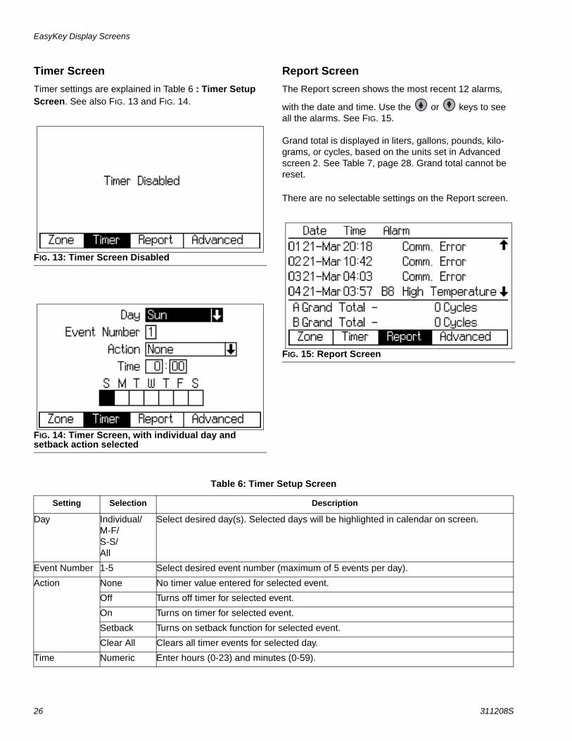
Timer ScreenTimer settings are explained in Table 6 : Timer Setup Screen. See also FIG. 13 and FIG. 14.
Report ScreenThe Report screen shows the most recent 12 alarms,
with the date and time. Use the or keys to see all the alarms. See FIG. 15.
Grand total is displayed in liters, gallons, pounds, kilo-grams, or cycles, based on the units set in Advanced screen 2. See Table 7, page 28. Grand total cannot be reset.
There are no selectable settings on the Report screen.
FIG. 13: Timer Screen Disabled
FIG. 14: Timer Screen, with individual day and setback action selected
FIG. 15: Report Screen
Table 6: Timer Setup Screen
Setting Selection Description
Day Individual/M-F/S-S/All
Select desired day(s). Selected days will be highlighted in calendar on screen.
Event Number 1-5 Select desired event number (maximum of 5 events per day).
Action None No timer value entered for selected event.
Off Turns off timer for selected event.
On Turns on timer for selected event.
Setback Turns on setback function for selected event.
Clear All Clears all timer events for selected day.
Time Numeric Enter hours (0-23) and minutes (0-59).
EasyKey Display Screens
311208S 27
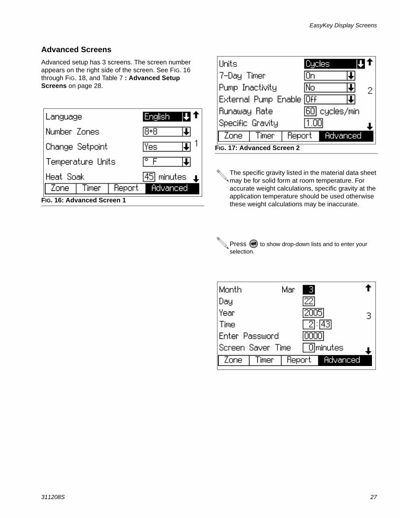
Advanced ScreensAdvanced setup has 3 screens. The screen number appears on the right side of the screen. See FIG. 16 through FIG. 18, and Table 7 : Advanced Setup Screens on page 28.
FIG. 16: Advanced Screen 1
FIG. 17: Advanced Screen 2
The specific gravity listed in the material data sheet may be for solid form at room temperature. For accurate weight calculations, specific gravity at the application temperature should be used otherwise these weight calculations may be inaccurate.
Press to show drop-down lists and to enter your selection.
EasyKey Display Screens
28 311208S
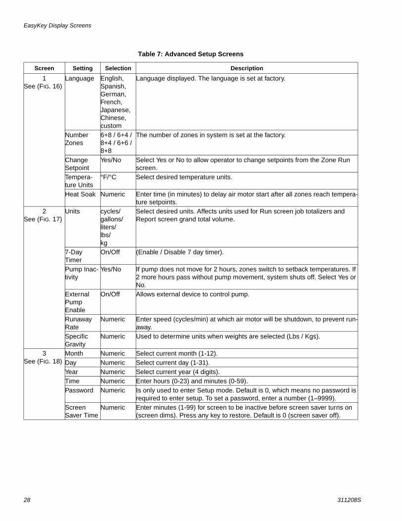
Table 7: Advanced Setup Screens
Screen Setting Selection Description
1See (FIG. 16)
Language English, Spanish, German, French, Japanese, Chinese, custom
Language displayed. The language is set at factory.
Number Zones
6+8 / 6+4 / 8+4 / 6+6 / 8+8
The number of zones in system is set at the factory.
Change Setpoint
Yes/No Select Yes or No to allow operator to change setpoints from the Zone Run screen.
Tempera-ture Units
°F/°C Select desired temperature units.
Heat Soak Numeric Enter time (in minutes) to delay air motor start after all zones reach tempera-ture setpoints.
2See (FIG. 17)
Units cycles/gallons/liters/lbs/kg
Select desired units. Affects units used for Run screen job totalizers and Report screen grand total volume.
7-Day Timer
On/Off (Enable / Disable 7 day timer).
Pump Inac-tivity
Yes/No If pump does not move for 2 hours, zones switch to setback temperatures. If 2 more hours pass without pump movement, system shuts off. Select Yes or No.
External Pump Enable
On/Off Allows external device to control pump.
Runaway Rate
Numeric Enter speed (cycles/min) at which air motor will be shutdown, to prevent run-away.
Specific Gravity
Numeric Used to determine units when weights are selected (Lbs / Kgs).
3See (FIG. 18)
Month Numeric Select current month (1-12).Day Numeric Select current day (1-31).Year Numeric Select current year (4 digits).Time Numeric Enter hours (0-23) and minutes (0-59).Password Numeric Is only used to enter Setup mode. Default is 0, which means no password is
required to enter setup. To set a password, enter a number (1–9999).Screen Saver Time
Numeric Enter minutes (1-99) for screen to be inactive before screen saver turns on (screen dims). Press any key to restore. Default is 0 (screen saver off).
Setup
311208S 29
Setup
Purge Before Using EquipmentThe equipment was tested with lightweight oil, which is left in the fluid passages to protect parts. To avoid con-taminating your fluid with oil, purge the equipment with a compatible material before using the equipment. See Purging the System, page 20.
Set Values on EasyKeySet desired values on EasyKey setup menus. See Setup Mode, page 24.
Material Loading
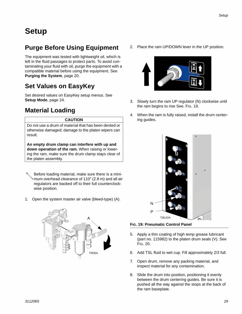
1. Open the system master air valve (bleed-type) (A).
2. Place the ram UP/DOWN lever in the UP position.
3. Slowly turn the ram UP regulator (N) clockwise until the ram begins to rise See. FIG. 19.
4. When the ram is fully raised, install the drum center-ing guides.
5. Apply a thin coating of high temp grease lubricant (part no. 115982) to the platen drum seals (V). See FIG. 20.
6. Add TSL fluid to wet cup. Fill approximately 2/3 full.
7. Open drum, remove any packing material, and inspect material for any contamination.
8. Slide the drum into position, positioning it evenly between the drum centering guides. Be sure it is pushed all the way against the stops at the back of the ram baseplate.
CAUTIONDo not use a drum of material that has been dented or otherwise damaged; damage to the platen wipers can result.
An empty drum clamp can interfere with up and down operation of the ram. When raising or lower-ing the ram, make sure the drum clamp stays clear of the platen assembly.
Before loading material, make sure there is a mini-mum overhead clearance of 110" (2.8 m) and all air regulators are backed off to their full counterclock-wise position.
A
TI835A
FIG. 19: Pneumatic Control Panel
N
PTI8142A

Setup
30 311208S
9. Remove the platen bleed handle (W). See FIG. 20.
10. Place the ram UP/DOWN lever in the DOWN posi-tion.
11. See FIG. 19. Slowly turn the ram DOWN regulator (P) clockwise to approximately 5-10 psi (34-69 kPa, 0.3-0.7 bar). The platen will begin to lower into the drum.
12. After the platen seals (V) enter the material drum, adjust the ram DOWN air regulator (P) to 30-50 psi (207-345 kPa, 2.1-3.4 bar). See FIG. 19 and FIG. 20.
13. When the ram stops, reinsert the platen bleed han-dle (W) and hand tighten. See FIG. 20.
CAUTIONLowering the ram without a drum in place can dam-age the drum centering guides (if equipped).
TI8141A
FIG. 20: Platen
W VTI8143A
Setup
311208S 31
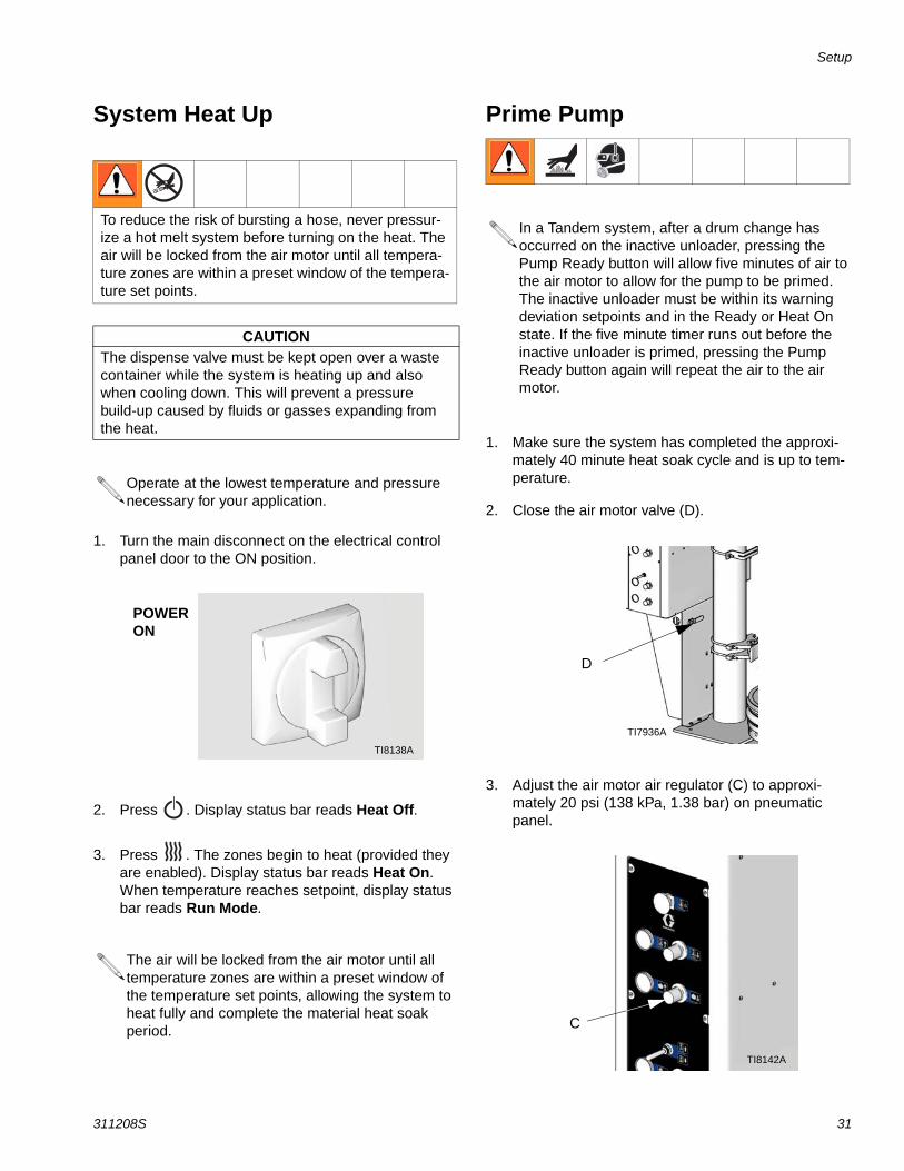
System Heat Up
1. Turn the main disconnect on the electrical control panel door to the ON position.
2. Press . Display status bar reads Heat Off.
3. Press . The zones begin to heat (provided they are enabled). Display status bar reads Heat On. When temperature reaches setpoint, display status bar reads Run Mode.
Prime Pump
1. Make sure the system has completed the approxi-mately 40 minute heat soak cycle and is up to tem-perature.
2. Close the air motor valve (D).
3. Adjust the air motor air regulator (C) to approxi-mately 20 psi (138 kPa, 1.38 bar) on pneumatic panel.
To reduce the risk of bursting a hose, never pressur-ize a hot melt system before turning on the heat. The air will be locked from the air motor until all tempera-ture zones are within a preset window of the tempera-ture set points.
CAUTIONThe dispense valve must be kept open over a waste container while the system is heating up and also when cooling down. This will prevent a pressure build-up caused by fluids or gasses expanding from the heat.
Operate at the lowest temperature and pressure necessary for your application.
The air will be locked from the air motor until all temperature zones are within a preset window of the temperature set points, allowing the system to heat fully and complete the material heat soak period.
POWER ON
TI8138A
In a Tandem system, after a drum change has occurred on the inactive unloader, pressing the Pump Ready button will allow five minutes of air to the air motor to allow for the pump to be primed. The inactive unloader must be within its warning deviation setpoints and in the Ready or Heat On state. If the five minute timer runs out before the inactive unloader is primed, pressing the Pump Ready button again will repeat the air to the air motor.
D
TI7936A
C
TI8142A

Setup
32 311208S
4. Place a waste container under the bleed stem (Z). Using an adjustable wrench, open the bleed stem counterclockwise 1/3 -1/2 turn. See FIG. 21.
5. If a new drum was installed and the unit is equipped with proximity sensors, press the Pump Ready but-
ton . If the unit is not equipped with proximity
sensors, press the Clear button if a motor error is present, then press the Pump Ready button
.
6. With waste container in place, slowly open the air motor valve (D).
7. Make sure the pump begins to cycle and heated material flows from the bleed stem (Z) after several cycles of the pump.
8. If the pump does not cycle, close the pump bleed-type master air valve (D), adjust the air motor air regulator (C) up by 5 psi (34 kPa, 0.3 bar). Never adjust the regulator by more than 5 psi (34 kPa, 0.3 bar) increments.
9. Prime the pump until it moves smoothly in both directions with no air popping or erratic movement and close the pump bleed-type master air valve (D).
10. Close the bleed stem (Z). See FIG. 21.
D
TI7936A
FIG. 21: Bleed Stem
Z
TI8143A
Setup
311208S 33
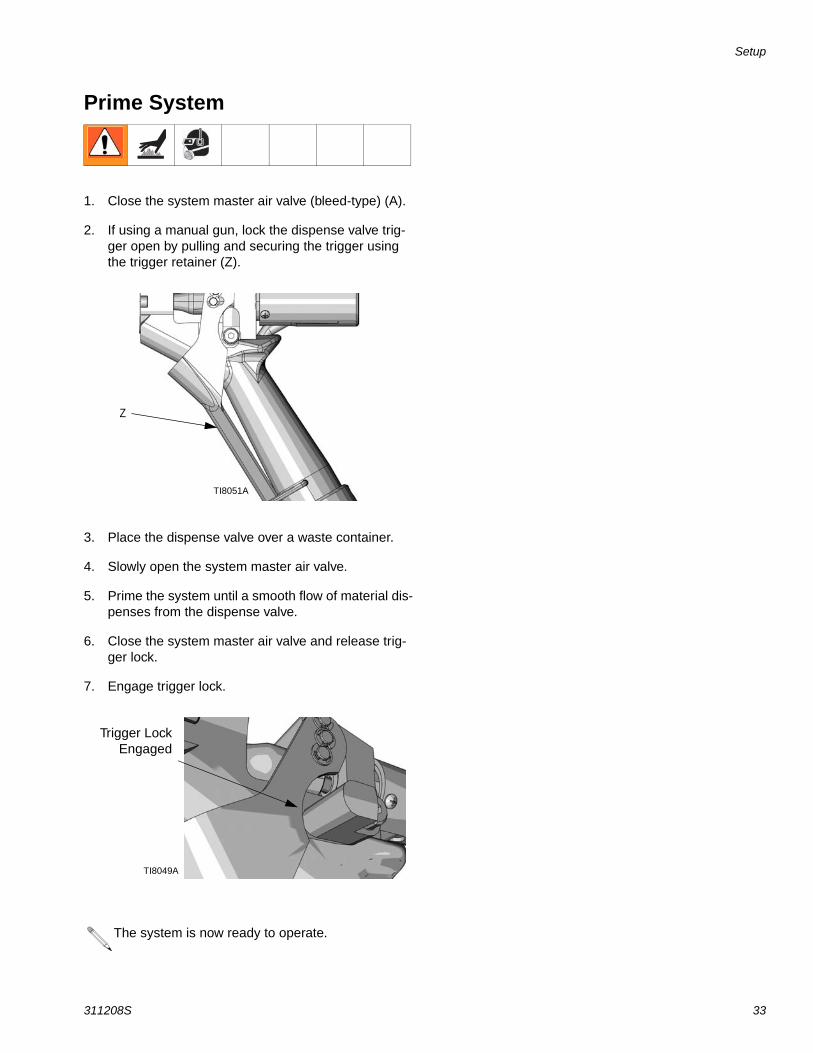
Prime System
1. Close the system master air valve (bleed-type) (A).
2. If using a manual gun, lock the dispense valve trig-ger open by pulling and securing the trigger using the trigger retainer (Z).
3. Place the dispense valve over a waste container.
4. Slowly open the system master air valve.
5. Prime the system until a smooth flow of material dis-penses from the dispense valve.
6. Close the system master air valve and release trig-ger lock.
7. Engage trigger lock.
The system is now ready to operate.
Z
TI8051A
Trigger LockEngaged
TI8049A
Operation
34 311208S
Operation
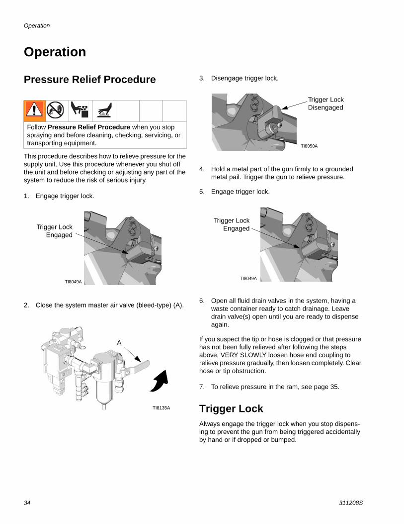
Pressure Relief Procedure
This procedure describes how to relieve pressure for the supply unit. Use this procedure whenever you shut off the unit and before checking or adjusting any part of the system to reduce the risk of serious injury.
1. Engage trigger lock.
2. Close the system master air valve (bleed-type) (A).
3. Disengage trigger lock.
4. Hold a metal part of the gun firmly to a grounded metal pail. Trigger the gun to relieve pressure.
5. Engage trigger lock.
6. Open all fluid drain valves in the system, having a waste container ready to catch drainage. Leave drain valve(s) open until you are ready to dispense again.
If you suspect the tip or hose is clogged or that pressure has not been fully relieved after following the steps above, VERY SLOWLY loosen hose end coupling to relieve pressure gradually, then loosen completely. Clear hose or tip obstruction.
7. To relieve pressure in the ram, see page 35.
Trigger LockAlways engage the trigger lock when you stop dispens-ing to prevent the gun from being triggered accidentally by hand or if dropped or bumped.
Follow Pressure Relief Procedure when you stop spraying and before cleaning, checking, servicing, or transporting equipment.
Trigger LockEngaged
TI8049A
A
TI8135A
Trigger Lock Disengaged
TI8050A
Trigger LockEngaged
TI8049A
Operation
311208S 35
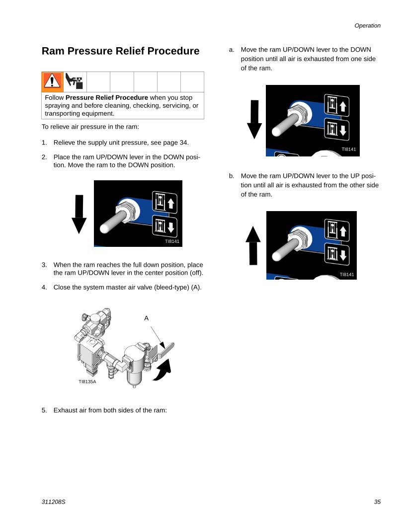
Ram Pressure Relief Procedure
To relieve air pressure in the ram:
1. Relieve the supply unit pressure, see page 34.
2. Place the ram UP/DOWN lever in the DOWN posi-tion. Move the ram to the DOWN position.
3. When the ram reaches the full down position, place the ram UP/DOWN lever in the center position (off).
4. Close the system master air valve (bleed-type) (A).
5. Exhaust air from both sides of the ram:
a. Move the ram UP/DOWN lever to the DOWN position until all air is exhausted from one side of the ram.
b. Move the ram UP/DOWN lever to the UP posi-tion until all air is exhausted from the other side of the ram.
Follow Pressure Relief Procedure when you stop spraying and before cleaning, checking, servicing, or transporting equipment.
TI8141
A
TI8135A
TI8141
TI8141
Operation
36 311208S
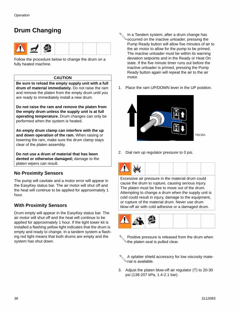
Drum Changing
Follow the procedure below to change the drum on a fully heated machine.
No Proximity SensorsThe pump will cavitate and a motor error will appear in the EasyKey status bar. The air motor will shut off and the heat will continue to be applied for approximately 1 hour.
With Proximity SensorsDrum empty will appear in the EasyKey status bar. The air motor will shut off and the heat will continue to be applied for approximately 1 hour. If the light tower kit is installed a flashing yellow light indicates that the drum is empty and ready to change. In a tandem system a flash-ing red light means that both drums are empty and the system has shut down.
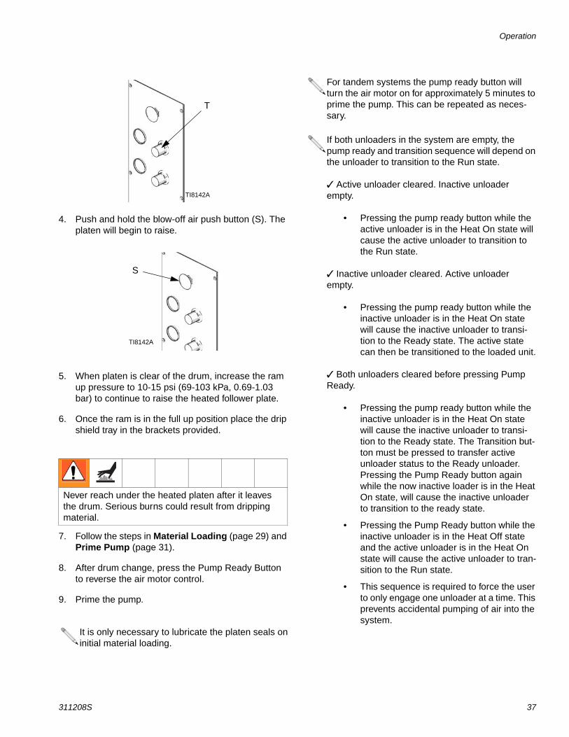
1. Place the ram UP/DOWN lever in the UP position.
2. Dial ram up regulator pressure to 0 psi.
3. Adjust the platen blow-off air regulator (T) to 20-30 psi (138-207 kPa, 1.4-2.1 bar).
CAUTIONBe sure to reload the empty supply unit with a full drum of material immediately. Do not raise the ram and remove the platen from the empty drum until you are ready to immediately install a new drum.
Do not raise the ram and remove the platen from the empty drum unless the supply unit is at full operating temperature. Drum changes can only be performed when the system is heated.
An empty drum clamp can interfere with the up and down operation of the ram. When raising or lowering the ram, make sure the drum clamp stays clear of the platen assembly.
Do not use a drum of material that has been dented or otherwise damaged; damage to the platen wipers can result.
In a Tandem system, after a drum change has occurred on the inactive unloader, pressing the Pump Ready button will allow five minutes of air to the air motor to allow for the pump to be primed. The inactive unloader must be within its warning deviation setpoints and in the Ready or Heat On state. If the five minute timer runs out before the inactive unloader is primed, pressing the Pump Ready button again will repeat the air to the air motor.
Excessive air pressure in the material drum could cause the drum to rupture, causing serious injury. The platen must be free to move out of the drum. Attempting to change a drum when the supply unit is cold could result in injury, damage to the equipment, or rupture of the material drum. Never use drum blow-off air with cold adhesive or a damaged drum.
Positive pressure is released from the drum when the platen seal is pulled clear.
A splatter shield accessory for low viscosity mate-rial is available.
TI8135A
Operation
311208S 37
4. Push and hold the blow-off air push button (S). The platen will begin to raise.
5. When platen is clear of the drum, increase the ram up pressure to 10-15 psi (69-103 kPa, 0.69-1.03 bar) to continue to raise the heated follower plate.
6. Once the ram is in the full up position place the drip shield tray in the brackets provided.
7. Follow the steps in Material Loading (page 29) and Prime Pump (page 31).
8. After drum change, press the Pump Ready Button to reverse the air motor control.
9. Prime the pump.
Never reach under the heated platen after it leaves the drum. Serious burns could result from dripping material.
It is only necessary to lubricate the platen seals on initial material loading.
T
TI8142A
S
TI8142A
For tandem systems the pump ready button will turn the air motor on for approximately 5 minutes to prime the pump. This can be repeated as neces-sary.
If both unloaders in the system are empty, the pump ready and transition sequence will depend on the unloader to transition to the Run state.
Active unloader cleared. Inactive unloader empty.
• Pressing the pump ready button while the active unloader is in the Heat On state will cause the active unloader to transition to the Run state.
Inactive unloader cleared. Active unloader empty.
• Pressing the pump ready button while the inactive unloader is in the Heat On state will cause the inactive unloader to transi-tion to the Ready state. The active state can then be transitioned to the loaded unit.
Both unloaders cleared before pressing Pump Ready.
• Pressing the pump ready button while the inactive unloader is in the Heat On state will cause the inactive unloader to transi-tion to the Ready state. The Transition but-ton must be pressed to transfer active unloader status to the Ready unloader. Pressing the Pump Ready button again while the now inactive loader is in the Heat On state, will cause the inactive unloader to transition to the ready state.
• Pressing the Pump Ready button while the inactive unloader is in the Heat Off state and the active unloader is in the Heat On state will cause the active unloader to tran-sition to the Run state.
• This sequence is required to force the user to only engage one unloader at a time. This prevents accidental pumping of air into the system.
Operation
38 311208S
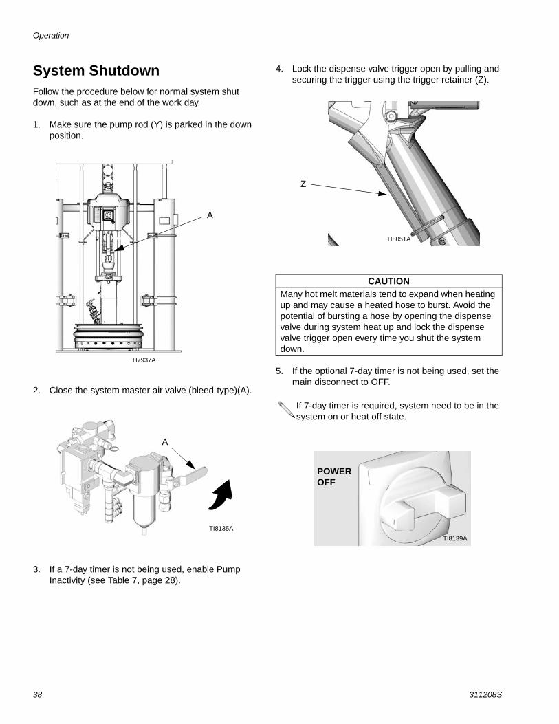
System ShutdownFollow the procedure below for normal system shut down, such as at the end of the work day.
1. Make sure the pump rod (Y) is parked in the down position.
2. Close the system master air valve (bleed-type)(A).
3. If a 7-day timer is not being used, enable Pump Inactivity (see Table 7, page 28).
4. Lock the dispense valve trigger open by pulling and securing the trigger using the trigger retainer (Z).
5. If the optional 7-day timer is not being used, set the main disconnect to OFF.
TI7937A
A
A
TI8135A
CAUTIONMany hot melt materials tend to expand when heating up and may cause a heated hose to burst. Avoid the potential of bursting a hose by opening the dispense valve during system heat up and lock the dispense valve trigger open every time you shut the system down.
If 7-day timer is required, system need to be in the system on or heat off state.
Z
TI8051A
TI8139A
POWER OFF
Dual Ram Cross-Over Installation
311208S 39
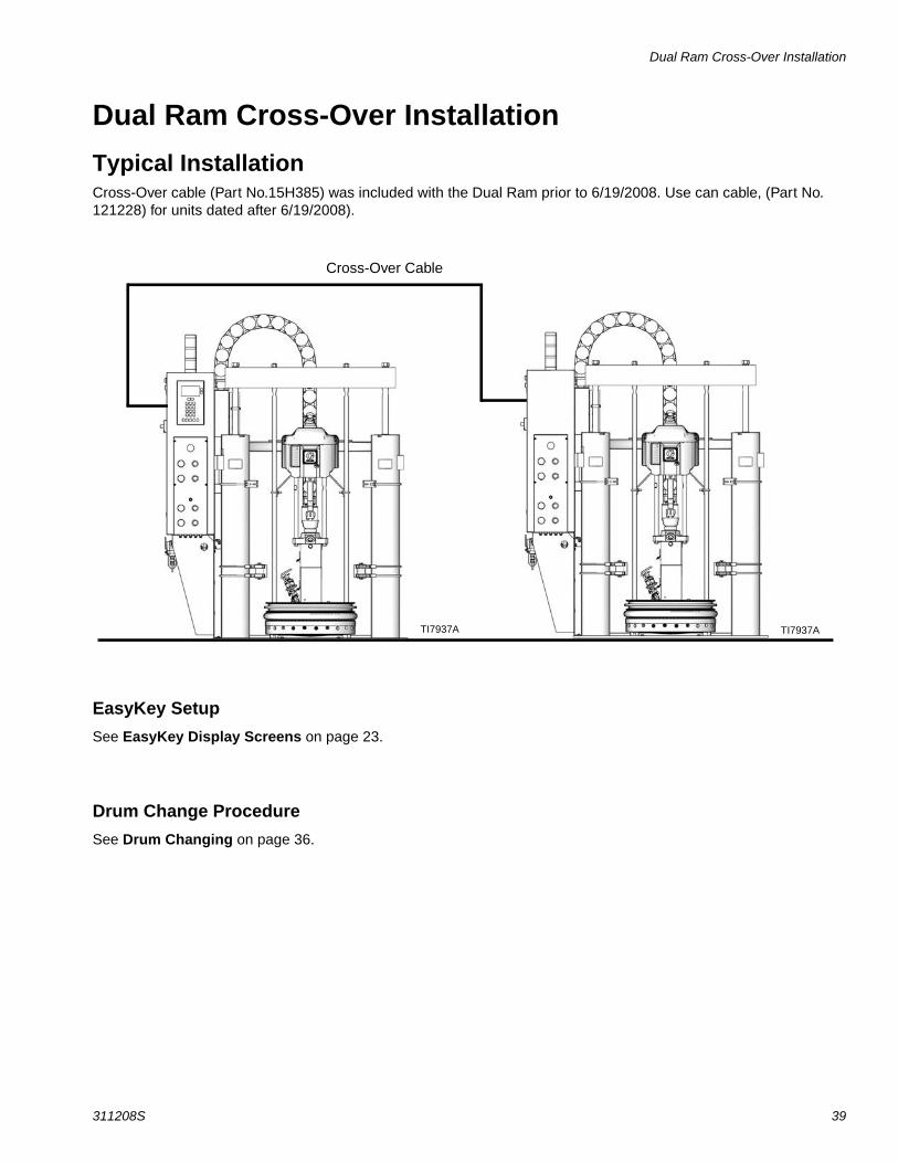
Dual Ram Cross-Over InstallationTypical InstallationCross-Over cable (Part No.15H385) was included with the Dual Ram prior to 6/19/2008. Use can cable, (Part No. 121228) for units dated after 6/19/2008).
EasyKey SetupSee EasyKey Display Screens on page 23.
Drum Change ProcedureSee Drum Changing on page 36.
Cross-Over Cable
TI7937A TI7937A
Maintenance
40 311208S
Maintenance
RamPeriodically (at least once a month), inspect the ram guide sleeves, rods and cylinders for wear or damage. See instruction manual 310523.
Ground Fault InterruptPeriodically (at least once a month) test the ground fault interrupt switch by pushing the TEST button.
Power in a Tandem System
Resetting the Ground Fault Interrupt This electrical control panel is equipped with a ground fault interrupt (GFPE) circuit breaker. If the disconnect switch is ON, but all lights on the electrical control panel are off review troubleshooting procedures.
Alarm TroubleshootingThe Therm-O-Flow alarms alert you to a problem and help prevent system shut downs or application errors. If an alarm occurs, operation may stop and the following occurs.
• Light Tower Changes (if equipped)
• Status bar on the EasyKey Display shows the description
• Alarm out puts a signal sent to I/O
To Clear the alarm and restart the TOF 200 press the Error Clear key on the EasyKey display.
See Table 8 : Therm-O-Flow Alarms.
In a Tandem System, the secondary unloader pro-vides 24VDC power to the EasyKey display. This allows the primary unloader to be powered down for maintenance without interrupting production. All accessories (light tower, swirl, etc.) and the display board on the primary system will have power when the secondary unloader is powered on and the pri-mary unloader is powered off.
Alarm Troubleshooting
311208S 41
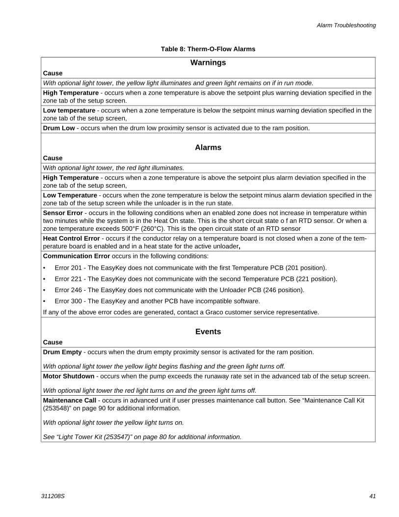
Table 8: Therm-O-Flow Alarms
WarningsCauseWith optional light tower, the yellow light illuminates and green light remains on if in run mode.High Temperature - occurs when a zone temperature is above the setpoint plus warning deviation specified in the zone tab of the setup screen.
Low temperature - occurs when a zone temperature is below the setpoint minus warning deviation specified in the zone tab of the setup screen,
Drum Low - occurs when the drum low proximity sensor is activated due to the ram position.
AlarmsCauseWith optional light tower, the red light illuminates.High Temperature - occurs when a zone temperature is above the setpoint plus alarm deviation specified in the zone tab of the setup screen,
Low Temperature - occurs when the zone temperature is below the setpoint minus alarm deviation specified in the zone tab of the setup screen while the unloader is in the run state.
Sensor Error - occurs in the following conditions when an enabled zone does not increase in temperature within two minutes while the system is in the Heat On state. This is the short circuit state o f an RTD sensor. Or when a zone temperature exceeds 500°F (260°C). This is the open circuit state of an RTD sensor
Heat Control Error - occurs if the conductor relay on a temperature board is not closed when a zone of the tem-perature board is enabled and in a heat state for the active unloader,Communication Error occurs in the following conditions:
• Error 201 - The EasyKey does not communicate with the first Temperature PCB (201 position).
• Error 221 - The EasyKey does not communicate with the second Temperature PCB (221 position).
• Error 246 - The EasyKey does not communicate with the Unloader PCB (246 position).
• Error 300 - The EasyKey and another PCB have incompatible software.
If any of the above error codes are generated, contact a Graco customer service representative.
EventsCauseDrum Empty - occurs when the drum empty proximity sensor is activated for the ram position.
With optional light tower the yellow light begins flashing and the green light turns off.Motor Shutdown - occurs when the pump exceeds the runaway rate set in the advanced tab of the setup screen.
With optional light tower the red light turns on and the green light turns off.Maintenance Call - occurs in advanced unit if user presses maintenance call button. See “Maintenance Call Kit (253548)” on page 90 for additional information.
With optional light tower the yellow light turns on.
See “Light Tower Kit (253547)” on page 80 for additional information.

Ram Troubleshooting
42 311208S
Ram Troubleshooting
Problem Cause Solution
Ram will not raise or lower. Closed main air valve or clogged air line,
Open air valve; clear air line.
Not enough ram air pressure. Increase ram air pressure.
Worn or damaged ram piston. Replace piston. See instruction man-ual 310523.
Platen not fully up to temperature. Wait for full temperature.
Ram air pressure too high. Decrease ram air pressure.
Dented drum has stopped platen. Fix or replace drum.
Ram raises or lowers too fast. Ram “up / down” air pressure too high.
Decrease ram air pressure.
Air leaks around cylinder rod. Worn rod seal. Replace o-rings in guide sleeve. See instruction manual 310523.
Fluid squeezes past platen wipers. Ram air pressure too high. Decrease ram air pressure.
Worn or damaged wipers. Replace wipers.
Directional valve not in the down position.
Position handle in the down position.
Pump will not prime properly, or pumps air.
Closed main air valve or clogged air line.
Open air valve; clear air line.
Not enough air pressure. Increase air pressure.
Worn or damaged ram piston. Replace piston. See instruction man-ual 310523.
Ram directional valve closed or clogged.
Open valve; clear valve or exhaust.
Ram directional valve dirty, worn, or damaged.
Clean; repair valve.
Dented drum has stopped platen. Fix or replace drum.
Air pressure will not push platen out of drum.
Closed main air valve or clogged air line.
Open air valve; clear air line.
Platen no fully up to temperature. Wait for full temperature.
Not enough blow-off air pressure. Increase blow-off air pressure.
Blow-off valve passage clogged. Clean valve passage.
Dented drum has stopped platen. Fix or replace drum.
Wipers bonded to drum or drum liner. Lubricate wipers with high tempera-ture grease at every drum change.
Heated Pump Troubleshooting
311208S 43
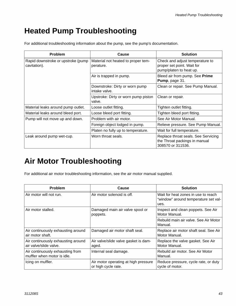
Heated Pump TroubleshootingFor additional troubleshooting information about the pump, see the pump’s documentation.
Air Motor TroubleshootingFor additional air motor troubleshooting information, see the air motor manual supplied.
Problem Cause Solution
Rapid downstroke or upstroke (pump cavitation).
Material not heated to proper tem-perature.
Check and adjust temperature to proper set point. Wait for pump/platen to heat up.
Air is trapped in pump. Bleed air from pump. See Prime Pump, page 31.
Downstroke: Dirty or worn pump intake valve.
Clean or repair. See Pump Manual.
Upstroke: Dirty or worn pump piston valve.
Clean or repair.
Material leaks around pump outlet. Loose outlet fitting. Tighten outlet fitting.
Material leaks around bleed port. Loose bleed port fitting. Tighten bleed port fitting.
Pump will not move up and down. Problem with air motor. See Air Motor Manual.
Foreign object lodged in pump. Relieve pressure. See Pump Manual.
Platen no fully up to temperature. Wait for full temperature.
Leak around pump wet-cup. Worn throat seals. Replace throat seals. See Servicing the Throat packings in manual 308570 or 311536.
Problem Cause Solution
Air motor will not run. Air motor solenoid is off. Wait for heat zones in use to reach “window” around temperature set val-ues.
Air motor stalled. Damaged main air valve spool or poppets.
Inspect and clean poppets. See Air Motor Manual.
Rebuild main air valve. See Air Motor Manual.
Air continuously exhausting around air motor shaft.
Damaged air motor shaft seal. Replace air motor shaft seal. See Air Motor Manual.
Air continuously exhausting around air valve/slide valve.
Air valve/slide valve gasket is dam-aged.
Replace the valve gasket. See Air Motor Manual.
Air continuously exhausting from muffler when motor is idle.
Internal seal damage. Rebuild air motor. See Air Motor Manual.
Icing on muffler. Air motor operating at high pressure or high cycle rate.
Reduce pressure, cycle rate, or duty cycle of motor.

Electrical Control Panel Troubleshooting
44 311208S
Electrical Control Panel Troubleshooting
Problem Cause Solution
Disconnect is ON, but EasyKey not lit.
The ground fault interrupt has been activated.
Have a qualified electrician check wiring.
One or more fuses or circuit breakers tripped.
Have a qualified electrician check wiring.
High temperature alarm. The temperature of a heated compo-nent has gone out of range.
Supply unit automatically turns off power to supply unit components and air motor. Unit turns power back on when overheated components reach appropriate temperatures.
Heat is turned off after a period of pump inactivity.
Pump has not moved within the pro-grammed time period and the inactiv-ity timer has been triggered.
See Table 7, page 28.
Pump Ready button does not clear flashing pump ready icon.
Unloader not in Heat On state and/or zones have not reached warning deviation level.
Turn system to Heat On state and wait until all zones reach warning deviation level.
Service
311208S 45
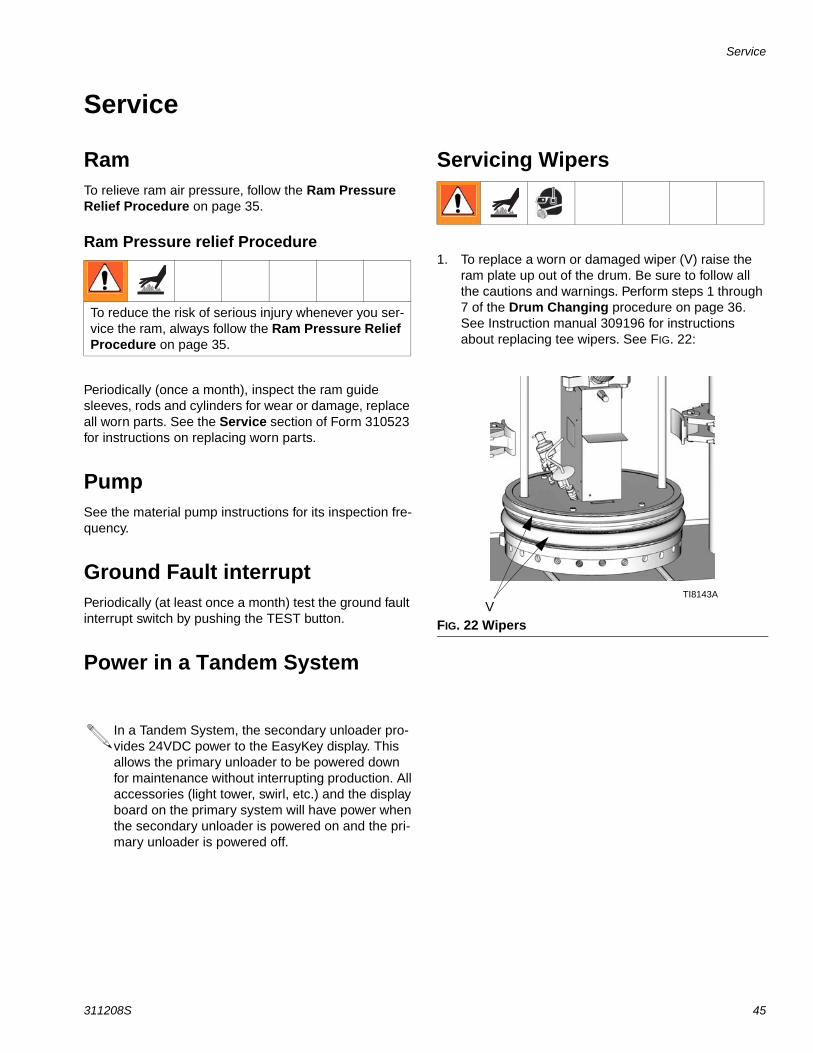
Service
RamTo relieve ram air pressure, follow the Ram Pressure Relief Procedure on page 35.
Ram Pressure relief Procedure
Periodically (once a month), inspect the ram guide sleeves, rods and cylinders for wear or damage, replace all worn parts. See the Service section of Form 310523 for instructions on replacing worn parts.
PumpSee the material pump instructions for its inspection fre-quency.
Ground Fault interruptPeriodically (at least once a month) test the ground fault interrupt switch by pushing the TEST button.
Power in a Tandem System
Servicing Wipers
1. To replace a worn or damaged wiper (V) raise the ram plate up out of the drum. Be sure to follow all the cautions and warnings. Perform steps 1 through 7 of the Drum Changing procedure on page 36. See Instruction manual 309196 for instructions about replacing tee wipers. See FIG. 22:
To reduce the risk of serious injury whenever you ser-vice the ram, always follow the Ram Pressure Relief Procedure on page 35.
In a Tandem System, the secondary unloader pro-vides 24VDC power to the EasyKey display. This allows the primary unloader to be powered down for maintenance without interrupting production. All accessories (light tower, swirl, etc.) and the display board on the primary system will have power when the secondary unloader is powered on and the pri-mary unloader is powered off.
FIG. 22 WipersV
TI8143A
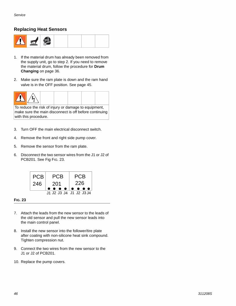
Service
46 311208S
Replacing Heat Sensors
1. If the material drum has already been removed from the supply unit, go to step 2. If you need to remove the material drum, follow the procedure for Drum Changing on page 36.
2. Make sure the ram plate is down and the ram hand valve is in the OFF position. See page 45.
3. Turn OFF the main electrical disconnect switch.
4. Remove the front and right side pump cover.
5. Remove the sensor from the ram plate.
6. Disconnect the two sensor wires from the J1 or J2 of PCB201. See Fig FIG. 23.
7. Attach the leads from the new sensor to the leads of the old sensor and pull the new sensor leads into the main control panel.
8. Install the new sensor into the follower/tire plate after coating with non-silicone heat sink compound. Tighten compression nut.
9. Connect the two wires from the new sensor to the J1 or J2 of PCB201.
10. Replace the pump covers.
To reduce the risk of injury or damage to equipment, make sure the main disconnect is off before continuing with this procedure.
FIG. 23
PCB246
PCB201
PCB226
J1 J2 J3 J4 J1 J2 J3 J4

Pump Removal and Replacement
311208S 47
Pump Removal and ReplacementFor information about servicing the Check-Mate™ 800 Displacement Pump, see Instruction Manual 308570.
1. If the material drum has already been removed from the supply unit, go to step 2. If you need to remove the material drum, perform steps 1 through 6 of the Drum Changing procedure on page 36. It is import-ant that the pump rod is in the fully down (parked) position.
2. Make sure the ram plate is down and the ram hand valve is in the neutral position.
3. Bleed off excess material and pressure in the sys-tem by opening the dispense gun and catching the material in a waste container.
4. On the electrical control panel, turn off the system heat (D). See FIG. 24.
5. Turn OFF the main electrical power supply to the unit. Follow all applicable safety procedures and lockout rules.
6. Turn OFF the main electrical disconnect (E) located on the left side of the Them-O-Flow 200.
7. Disconnect all material hoses.
8. Remove the pump sheet metal enclosure (A). See FIG. 24.
a. Remove the cover screws (B).
b. Disconnect the pump heater wires, the ground wire, and the sensor mounted to the pump.
c. Remove the follower sensor (C).
9. Pump must be in the full down position (air motor shaft fully extended).
Reverse the above procedure to reinstall a new or rebuilt pump.
Separating the Air Motor from the Pump
1. If vent hood is installed, remove it.
2. Remove the air motor top cover.
3. Disconnect electrical cable from air motor.
4. Remove air line from air motor and air lines to the follower blow-off valve.
5. Tightly strap the air motor to the tie bar with a cable through the air motor lift ring and around the tie bar.
6. Loosen U-bolts from follower lift rods.
7. Remove nuts (F) from pump/air motor stand-off rods at the pump end. See FIG. 24.
8. Remove nuts and bolts holding cable tract to air motor support plate.
9. Slide end of cable track outboard of the mounting plate.
10. Remove nuts (2) from follower lift rods.
11. Fully loosen pump rod coupler to the air motor rod (G).
12. Slowly raise elevator to achieve enough separation of the pump (air motor) tie rods to remove the pump.
13. Remove the pump.
14. Reverse this procedure to reinstall the new or rebuilt air motor.
To reduce the risk of serious injury whenever you are instructed to relieve pressure, always follow the Pres-sure Relief Procedure on page 34.
To reduce the risk of injury or damage to equipment, make sure the main disconnect is off before continuing with this procedure.
This procedure must be done with the unit still warm. The material and equipment will be hot!
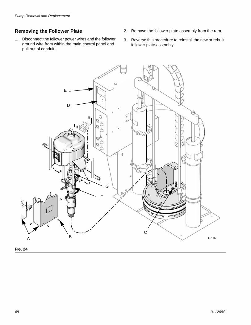
Pump Removal and Replacement
48 311208S
Removing the Follower Plate1. Disconnect the follower power wires and the follower
ground wire from within the main control panel and pull out of conduit.
2. Remove the follower plate assembly from the ram.
3. Reverse this procedure to reinstall the new or rebuilt follower plate assembly.
FIG. 24
E
D
A BC
TI7832
F
G
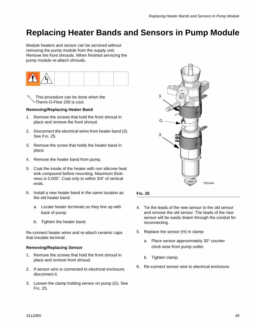
Replacing Heater Bands and Sensors in Pump Module
311208S 49
Replacing Heater Bands and Sensors in Pump ModuleModule heaters and sensor can be serviced without removing the pump module from the supply unit. Remove the front shrouds. When finished servicing the pump module re-attach shrouds.
Removing/Replacing Heater Band
1. Remove the screws that hold the front shroud in place and remove the front shroud.
2. Disconnect the electrical wires from heater band (3). See FIG. 25.
3. Remove the screw that holds the heater band in place.
4. Remove the heater band from pump.
5. Coat the inside of the heater with non silicone heat sink compound before mounting. Maximum thick-ness is 0.005”. Coat only to within 3/4” of vertical ends.
6. Install a new heater band in the same location as the old heater band:
a. Locate heater terminals so they line up with back of pump.
b. Tighten the heater band.
Re-connect heater wires and re-attach ceramic caps that insulate terminal.
Removing/Replacing Sensor
1. Remove the screws that hold the front shroud in place and remove front shroud.
2. If sensor wire is connected to electrical enclosure, disconnect it.
3. Loosen the clamp holding sensor on pump (G). See FIG. 25.
4. Tie the leads of the new sensor to the old sensor and remove the old sensor. The leads of the new sensor will be easily drawn through the conduit for reconnecting.
5. Replace the sensor (H) in clamp:
a. Place sensor approximately 30° counter clock-wise from pump outlet.
b. Tighten clamp.
6. Re-connect sensor wire to electrical enclosure.
This procedure can be done when the Therm-O-Flow 200 is cool.
FIG. 25
3
3
G
TI8144A
Replacing Heater Bands and Sensors in Pump Module
50 311208S
Removing/Replacing RTD Sensor
1. Remove the screws that hold the front shroud in place and remove front shroud.
2. If RTD sensor wire is connected to electrical enclo-sure, disconnect it.
3. Loosen the clamp holding sensor on pump.
4. Tie the leads of the new RTD sensor to the old RTD sensor and remove the old sensor. The leads of the new sensor will be easily drawn through the conduit for reconnecting.
5. Remove RTD sensor.
6. Replace the sensor (H) in clamp:
a. Place RTD sensor approximately 30° counter clock-wise from pump outlet.
b. Tighten clamp.
7. Re-connect sensor wire to electrical enclosure.
Inspection/Maintenance FrequencyThe pump packings do not require any other service or maintenance, except as described in the Daily Mainte-nance Procedures. See 308570 for inspection frequency of the pump.
Throat PackingsRefer to manual 308570 for a list of throat packing kits and replacement instructions.

Replacing Heater Bands and Sensors in Pump Module
311208S 51
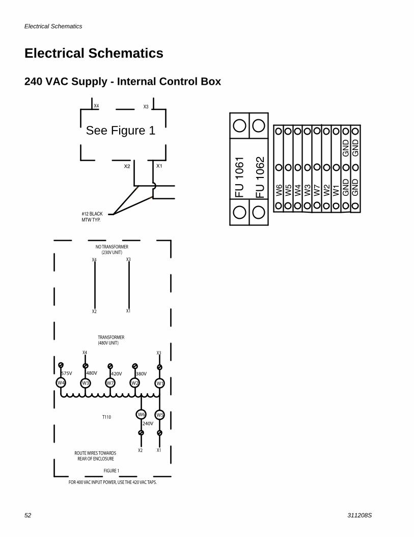
Electrical Schematics
52 311208S
Electrical Schematics
240 VAC Supply - Internal Control Box
X2 X1
#12 BLACK MTW TYP.
X4 X3
W4 W3 W2 W1
575V 480V 380V
W5W6
240V
X4 X3
X2 X1
TRANSFORMER(480V UNIT)
NO TRANSFORMER(230V UNIT)
X4 X3
X2 X1
FIGURE 1
T110
ROUTE WIRES TOWARDS REAR OF ENCLOSURE
W7
420V
FOR 400 VAC INPUT POWER, USE THE 420 VAC TAPS.
FU
106
1
FU
106
2
W6
W5
W4
W3
W2
W1
GN
DG
ND
GN
DG
ND
W7
See Figure 1

Electrical Schematics
311208S 53
Electrical Control Schematics
GFP
E 11
2C
ON
112
CO
N 1
01SS
R 13
0
FU 1
06
L1 L2 L3
1L1
1L2
1L3
SSR
106
5L1
FOLL
OW
ER G
ROU
ND
PUM
PH
EATE
RS(Z
ON
E 2)
1200
WTO
TAL
PUM
P G
ROU
ND
FU 1
16SS
R 11
6
FU 1
19SS
R 11
9
FU 1
22SS
R 12
2
HO
SE/A
UX
HEA
TER
#1 (ZO
NE
3) G
UN
/AU
X H
EATE
R#1 (Z
ON
E 4)
HO
SE/A
UX
HEA
TER
#2 (ZO
NE
5)
GU
N/A
UX
HEA
TER
#2 (ZO
NE
6)
DH
1-B
1
DH
2-A
1
DH
2-B
1
DG
1-1
DG
2-1
500W
1250
W M
AX
500W
DG
1-2
DG
2-2
DH
2-B
2
DH
2-A
2
DH
1-B
2
DIS
C
100
2L1
2L2
2L3
4L1
1131
1141
X2
X1
FU 1
13SS
R 11
3D
H1-
A1
1250
W M
AX
DH
1-A
2
FU 1
25SS
R 12
5
FU 1
28SS
R 12
8
HO
SE/A
UX
HEA
TER
#2 (ZO
NE
7)
DH
3-A
1
DH
3-B
1
DG
3-1
1250
W M
AX
500W
DG
3-2
DH
3-B
2
DH
3-A
2
200
200
GN
DFA
N1 2 3
4 5 6
H
12
12
12
12
12
12
12
12
34
56
12
NN
12
34
1271
1272
1132
1142
1133
1161
1191
1221
1251
1281
1134
1162 11
92
1222
1252
1282
3L3
3L2
3L1
A1
A2
221
FRO
M D
CIN
TF 2
21
A1
A2
4L2
FU 1
08T3T1T2B
1B
2
B3
109
111
1131 11
41
221
104
103 22
411
41
24 C
OM
+24
V
FU 1061
FU 1062
PS 1
22
NL
1211
1212
CD
E
F
A
B
AB CD EF
GRO
UN
DLU
G#1
2 BL
ACK
MTW
TYP
.
#12
BLAC
KM
TW T
YP.
#16
BLAC
KM
TW T
YP.
#12
BLAC
KM
TW T
YP.
#6 B
LACK
MTW
TYP
.
#6 G
REEN
MTW
TYP
.#6
BLA
CKM
TW T
YP.
#6 B
LACK
MTW
TYP
.
#12
GREE
N/YE
LLO
WM
TW T
YP.
#12
BLA
CK M
TW T
YP.
#12
BLAC
KM
TW T
YP.
FRO
M D
C IN
TRF
224
#12
BLAC
K M
TW T
YP.
SEE
FIGU
RE 1
X4X3
#12
BLAC
KM
TW T
YP
#12
BLAC
KM
TW T
YP
#14
AWG
#14
AWG
#14
AWG
#14
AWG
#14
AWG
#14
AWG
F D B E C A
3L1
3L2
3L3
F D B E C A
3L1
3L2
3L3
B2 B1 T2 T1 T3 B3
5L1
4L2
B2 B1 T2 T1 T3 B3
5L1
4L2
230V
480V
230V
480V
FIGU
RE 3
FIGU
RE 2
SEE
FIGU
RE3SE
EFI
GURE
2
WIR
ED A
T GR
ACO
WIR
ED A
T GR
ACO
246
246
300
300
319
305
312
224
224
222
100
101
102
103
104
105
106
107
108
109
110
111
112
113
114
115
116
117
118
119
120
121
122
123
124
125
126
127
128
100
101
102
103
104
105
106
107
108
109
110
111
112
113
114
115
116
117
118
119
120
121
122
123
124
125
126
127
128
LTR
ESE
E SHE
ET 1
FSE
E SHE
ET 1
GSE
E SHE
ET 1
HSE
E SHE
ET 1
JSE
E SHE
ET 1
W4
W3
W2
W1
575V
480V
380V
W5
W6 24
0V
X4X3
X2X1
TRAN
SFOR
MER
(480
V UN
IT)
NO TR
ANSF
ORM
ER(2
30V
UNIT
)X4
X3
X2X1
FIGUR
E 1
T110
ROUT
E WIR
ES TO
WAR
DS
REAR
OF E
NCLO
SUREW742
0V
FOR 4
00 VA
C IN
PUT P
OWER
, USE
THE 4
20 VA
C TAP
S.
TI8076A
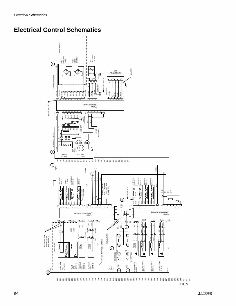
Electrical Schematics
54 311208S
Electrical Control Schematics
PCB 201 (TEMPERATURE BOARD #1)
RTD
SEN
SOR
100
P
LATI
NU
M
.003
85
/ /°
C
1 2
3 4
1 2
3 4
2 J6
8 7 6 5 4 3 2 1
J10
SSR
119
SSR
122
SSR
125
SSR
128
PCB 226 (TEMPERATURE BOARD #2)
J5
J5 J6
1
2
1 1
1 2 3 4 1 2 3 4 J6
SSR
130
SSR
106
SSR
113
SSR
116
FOLL
OW
ER
(ZO
NE
1)
PUM
P (Z
ON
E 2)
HO
SE/A
UX
#1
(ZO
NE
3)
GU
N/A
UX
#1
(ZO
NE
4)
FOLL
OW
ER
RTD
(Z
ON
E 1)
PUM
P RT
D
(ZO
NE
2)
HO
SE/A
UX
RT
D
(ZO
NE
3)
GU
N/A
UX
RT
D
(ZO
NE
4)
J10
J2
J3
J4
J1 1 2 1 2 1 2 1 2
8 7 6 5 4 3 2 1 5 6 7
J9
5 6 7
J9
DH
1-A
4
DH
1-A
5
DG
1-3
DG
1-4
DH
1-B
4
DH
1-B
5
PCB 246 (UNLOADER BOARD)
J4
1 2
1 2 3 4
J4
J2
J9
1 2 1 2 3 4 5 6 7 8
5 6 7
J1 1 2 3 4 5 6
J7
8 7
4 3
4 3
4 3
4 3
4 3
4 3
4 3
HO
SE/A
UX
#2
(ZO
NE
5)
HO
SE/A
UX
#3
(ZO
NE
7)
GU
N/A
UX
#2
(ZO
NE
6)
GU
N/A
UX
#3
(ZO
NE
8)
PRO
X.
SEN
SOR
#1
(LO
W)
PRO
X.
SEN
SOR
#2
(EM
PTY
)
AIR
SO
LEN
OID
C
BL
256
ANALOG SENSOR
REED SWITCHES
246
1272
247
248
249
250
251
252
253
254
255
256
257
258
259
260
261
24 A
WG
, TW
ISTE
D
PAIR
, 2 S
TRA
ND
ED
CO
ND
.,SH
IELD
ED
BEL
DEN
946
3
8 9 7
1 2 3
4
BK
GN
RD
BK
WH
BK
CB
L 24
7 JM
TOP
REED
HA
RNES
S 26
2
GN
/WH
CO
RD G
RIP
CO
RD G
RIP
CO
RD G
RIP
CO
RD G
RIP
128
128
128
128
EXTE
RNA
L TO
CO
NTR
OL
EXTE
RNA
L C
ON
TRO
L
2011
2021
2051
2061
2081
2091
2111
2121
1271
2231
+24
V
1271
2262
2282
2272
2292
2302
2311
2322
2332
1272
2142
2151
2561
2571
2012
2022
2032
2041
2052
2062
2071
2082
1272
2122
2131
2142
2151
1271
12
72
2561
2571
2482
(BN
)
2492
(BK
)
2502
(W
H)
2512
(BU
)
2522
(BN
)
2532
(BK
)
2541
(W
H)
2551
(BU
)
2572
(BN
)
2581
(BU
)
2481
2491
2501
2511
2521
2531
E1
E2
E2
E1
A1
A1 LI
NE
TO
CO
NN
10
1
LIN
E
DC
INTR
F 22
4
DC
INTR
F 22
1
1
J6
1271
J2
J1 1 2
1 2
GU
N/A
UX
#2
RTD
(Z
ON
E 6)
GU
N/A
UX
#2
RTD
(Z
ON
E 5)
DH
2-A
4
DH
2-A
5
DG
2-3
DG
2-4
DH
2-B
4
DH
2-B
5
2261
2271
2291
2301
J4
J3
1 2 1 2
GU
N/A
UX
#3
RTD
(Z
ON
E 8)
GU
N/A
UX
#3
RTD
(Z
ON
E 7)
DH
3-A
4
DH
3-A
5
DG
3-3
DG
3-4
DH
3-B
4
DH
3-B
5
2321
2331
2351
2361
2212
2222
11
3
113
1131
1131
24 C
OM
+24
V
24 C
OM
+24
V
+24
V
24 C
OM
302
303
RS48
5
RS48
5 RS
485
J3
1 2 3 4 5
FLOW CONTROL J264
#18
BLUE
MTW
TO B
E W
IRED
AS T
WIS
TED
PAIR
TYP
. (6) P
LACE
S
#18
BLUE
MTW
TYP
. (ALL
24V
PO
WER
)
#18
BLUE
MTW
TYP
.
#18
BLUE
MTW
TYP
. AL
L SS
R CO
IL W
IRIN
G
#20
AWG
TYP
#12
GREE
N M
TW T
YP
3
262
263
264
265
266
267
268
269
270
NC
2641
(BL)
2651
(BL)
2661
(BL)
2671
(BL)
1 2 3 4 5
#18
BLUE
MTW
TYP
WIR
ED A
T GR
ACO
BELD
EN 9
463
WIR
ED A
T GR
ACO
#18
BLUE
MTW
TYP
128
24 C
OM
12
72
128
TO D
IN R
AIL
MO
UNTI
NG S
CREW
103
200
201
202
203
204
205
206
207
208
209
210
211
212
213
214
215
216
217
218
219
220
221
222
223
224
225
226
227
228
229
230
231
232
233
234
235
236
237
238
239
240
241
242
243
244
245
TI8077

Electrical Schematics
311208S 55
Electrical Control SchematicsJ5
1 2
1 2 3
J5
PCB 300 (EASY KEY BOARD)
DH
1-C
2 D
G1-
7
GU
N S
WIT
CH
ES
DG
1-6
DH
1-C
1
1 2 3 4 5 6 7 8 9 10
11
0 1 2 3
1 2 3 4 5
1 2 3 4 5 6 7 8 9 10
11
12
13
14
15
16
17
18
19
20
1 2 3 4 5 6 7 8 9
2 3 2 3 4
7 8 9
1 2 3 4
1 4 5 6 10
11
12
13
15
16
17
18
MEM
BRA
NE
SWIT
CH
DIS
PLAY
J12
J7 J1
J4
J10
1 2 3 4 5 6 7 8 9 10
PCB
332
ETH
ERN
ET
CA
RD
CB
L334
J321 DIGITAL I/O INTERFACE
J332
1271
2122
2131
200
3021
3031
3041
3051
1272
200
J2
J3
J9
DH
2-C
2 D
G2-
7 D
G2-
6 D
H2-
C1
DH
3-C
2 D
G3-
7 D
G3-
6 D
H3-
C1
BRO
WN
RE
D
ORA
NG
E
WH
ITE/
PURP
LE
GRE
EN
BLU
E PU
RPLE
G
REY
W
HIT
E W
HIT
E/B
LAC
K
WH
ITE/
BRO
WN
W
HIT
E/RE
D
WH
ITE/
ORA
NG
E
WH
ITE/
YEL
LOW
W
HIT
E/G
REEN
W
HIT
E/B
LUE
212
213
+24
V
24 C
OM
200 12
71
+24
V
1272
LO
CA
L RS
485
SWIR
L SO
LEN
OID
#1
SWIR
L SO
LEN
OID
#2
EXTE
RNA
L TO
CO
NTR
OL
1 2 3 1 2 3
J305
J309
1272
1272
J6
1 2 3 4 5 6 1 2 3 4 J13
LT30
2
LIG
HT
TOW
ER
SWITCH
LAMP
SWITCH
A
B
C
D
E F
PB 3
15
#18
BLUE
MTW
TYP
.
MAI
NTEN
ANCE
CAL
L BU
TTO
N CO
NTAC
TS A
RE N
.O.
#20
AWG
TYP
#20
AWG
TYP
NC
NC
NC
NC
NC
NC
#18
BLUE
M
TW T
YP
1
J310
CRO
SS-
OV
ER
CO
MM
1 2 3
J11
BU WH
RED
BLA
CK
J14
1 2
5 4 1 32
HA
RNES
S 31
1
3121
3131
BELD
EN 9
501
200
1271
+2
4V
28
27
3321
33
31
10
14
WHI
TE/G
REY
YELL
OW
24 C
OM
1272
24
COM
1272
128
3151
31
52
19
5
300
301
302
303
304
305
306
307
308
309
310
311
312
313
314
315
316
317
318
319
320
321
322
323
324
325
326
327
328
329
330
335
333
334
331
332
336
337
TI8078A1
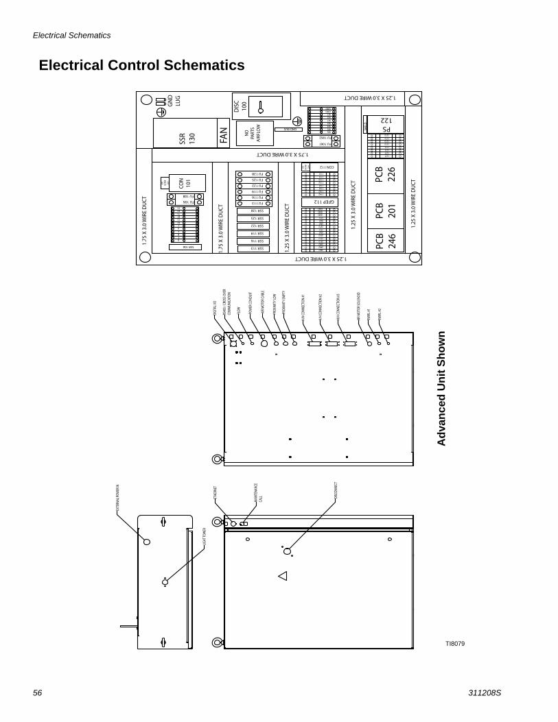
Electrical Schematics
56 311208S
Electrical Control Schematics
TI8079
O O
O O
O O
O O
O O
O O
O O
O
2482 2492 2502 2512 2522 2532 2541 2551 2572 2581 3021 3151 GND GND GND
O O
O O
O O
O O
O O
O O
O O
O
O O
O O
O O
O O
1142 1142 1141 1141 1132 1132 1131 1131
O O
O O
O O
O O
O O
O O
O O
O O
1271 1271 1271 1271 1272 1272 1272 1272
O O
O O
O O
O O
1.75
X 3
.0 W
IRE
DU
CT
GN
D
LUG
PCB
246
PCB
201
PCB
226
GFEP 112 FU 106
FU 108
FU 1061
FU 1062
SSR
130
FAN
D
ISC
10
0
CON
10
1
DC
IN
TRF
221
FU 113
FU 116
FU 119
FU 122
FU 125
FU 128
CON 112
DC
IN
TRF
224
PS 122
SSR 106 SSR 113
SSR 122
SSR 125
SSR 128
SSR 119
SSR 116 D F B E A C
B2
B1
B3
T2
T1
T3
W6 W5 W4 W3
W2W1
NO
PA
RTS
AIR
FLO
W
GND BUS
GNDGND
1.75
X 3
.0 W
IRE
DU
CT
1.25
X 3
.0 W
IRE
DU
CT
1.25
X 3
.0 W
IRE
DU
CT
1.25
X 3
.0 W
IRE
DU
CT
1.25 X 3.0 WIRE DUCT
1.75 X 3.0 WIRE DUCT
1.25 X 3.0 WIRE DUCT
SHIE
LD
DIGI
TAL I
/O
RS48
5 / C
ROSS
OVE
R
COM
MUN
ICAT
ION
FLOW
POW
ER C
ONDU
IT
AIR
MOT
OR C
ABLE
PROX
IMIT
Y LO
W
PROX
IMIT
Y EM
PTY
H/H
CONN
ECTI
ON #1
H/H
CONN
ECTI
ON #2
H/H
CONN
ECTI
ON #3
AIR
MOT
OR SO
LENO
ID
SWIR
L #1
SWIR
L #2
ETHE
RNET
MAI
NTEN
ANCE
CA
LL
DISC
ONNE
CT
EXTE
RNAL
POW
ER IN
LIGHT
TOW
ER
W7
Adv
ance
d U
nit S
how
n

Electrical Schematics
311208S 57
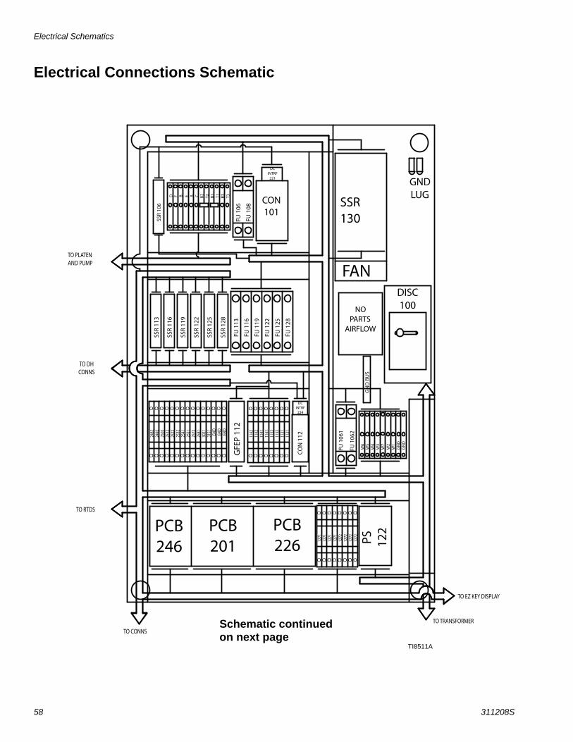
Electrical Schematics
58 311208S
Electrical Connections Schematic
O O O O O O O O O O O O O O O
2482
24
92
2502
25
12
2522
25
32
2541
25
51
2572
25
81
3021
31
51
GND
GND
GND
O O O O O O O O O O O O O O O
O O O O O O O O
1142
11
42
1141
11
41
1132
11
32
1131
11
31
O O O O O O O O
O O O O O O O O
1271
12
71
1271
12
71
1272
12
72
1272
12
72
O O O O O O O O
GND LUG
PCB 246
PCB 201
PCB 226
GFE
P 11
2 FU
106
FU 1
08
FU 1
061
FU 1
062
SSR 130
FAN DISC 100
CON 101
DC INTRF
221
FU 1
13
FU 1
16
FU 1
19
FU 1
22
FU 1
25
FU 1
28
CO
N 1
12
DC INTRF
224
PS
122
SSR
106
SSR
113
SSR
122
SSR
125
SSR
128
SSR
119
SSR
116
D
F B
E A
C
B2 B1
B3 T2
T1
T3
W6
W5
W4
W3
W2
W1
NO PARTS
AIRFLOW
GN
D B
US
GN
DG
ND
TO PLATEN AND PUMP
TO DH CONNS
TO RTDS
TO CONNS
TO TRANSFORMER
TO EZ KEY DISPLAY
W7
Schematic continued on next page
TI8511A
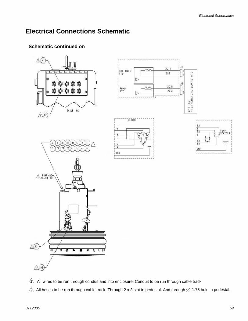
Electrical Schematics
311208S 59
Electrical Connections Schematic
Schematic continued on
1
2
All wires to be run through conduit and into enclosure. Conduit to be run through cable track.
All hoses to be run through cable track. Through 2 x 3 slot in pedestal. And through 1.75 hole in pedestal.
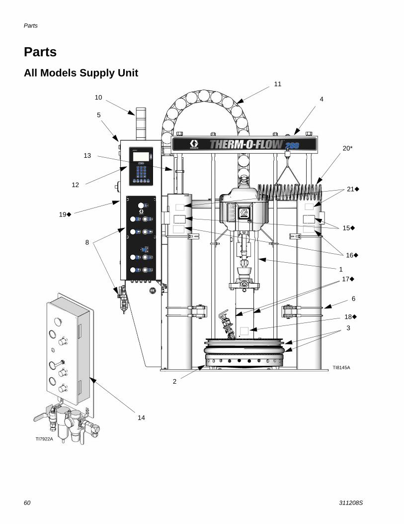
Parts
60 311208S
PartsAll Models Supply Unit
5
4
1
6
2
3
10
13
12
8
11
14
TI7922A
TI8145A
15
16
17
18
19
20*
21
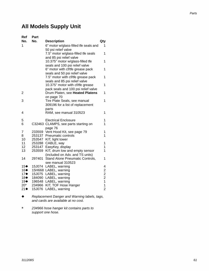
Parts
311208S 61
All Models Supply Unit
Ref No.
PartNo. Description Qty
1 6” motor w/glass-filled tfe seals and 50 psi relief valve
1
7.5” motor w/glass-filled tfe seals and 85 psi relief valve
1
10.375” motor w/glass-filled tfe seals and 100 psi relief valve
1
6” motor with cf/tfe grease pack seals and 50 psi relief valve
1
7.5” motor with cf/tfe grease pack seals and 85 psi relief valve
1
10.375” motor with cf/tfe grease pack seals and 100 psi relief valve
1
2 Drum Platen, see Heated Platens on page 70
1
3 Tire Plate Seals, see manual 309196 for a list of replacement parts
1
4 RAM, see manual 310523 1
5 Electrical Enclosure 16 C32463 CLAMPS, see parts starting on
page 761
7 233559 Vent Hood Kit, see page 79 18 253137 Pneumatic controls 110 253547 KIT, light tower11 253288 CABLE, way 112 253147 EasyKey, display 113 253559 KIT, drum low and empty sensor
(included on Adv. and TS units)1
14 297401 Stand Alone Pneumatic Controls, see manual 310523
1
15 15J074 LABEL, warning 416 15H668 LABEL, warning 217 15J075 LABEL, warning 218 184090 LABEL, warning 219 196548 LABEL, warning 120* 234966 KIT, TOF Hose Hanger 121 15J076 LABEL, warning 2
Replacement Danger and Warning labels, tags, and cards are available at no cost.
* 234966 hose hanger kit contains parts to support one hose.
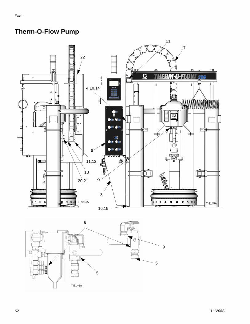
Parts
62 311208S
Therm-O-Flow Pump
22
11,13
18
20,21
16,19
3
9
6
4,10,14
11
17
9
5
6
5
TI8145ATI7934A
TI8146A
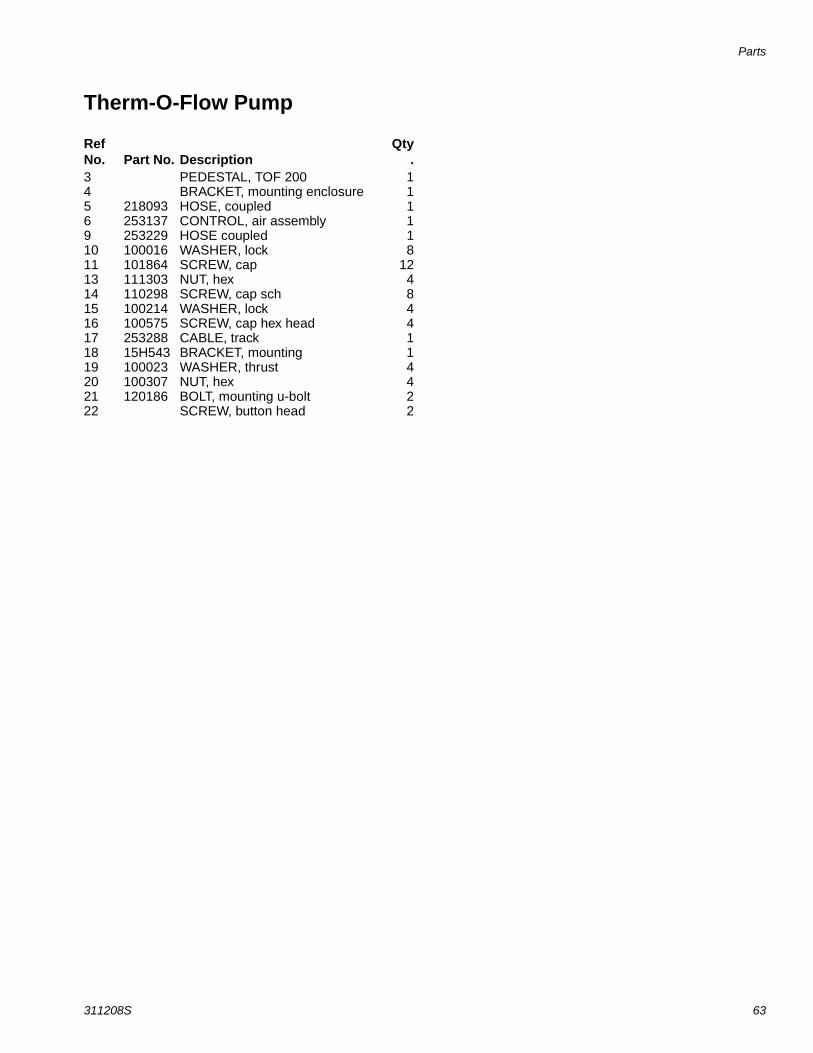
Parts
311208S 63
Therm-O-Flow Pump
Ref No. Part No. Description
Qty.
3 PEDESTAL, TOF 200 14 BRACKET, mounting enclosure 15 218093 HOSE, coupled 16 253137 CONTROL, air assembly 19 253229 HOSE coupled 110 100016 WASHER, lock 811 101864 SCREW, cap 1213 111303 NUT, hex 414 110298 SCREW, cap sch 815 100214 WASHER, lock 416 100575 SCREW, cap hex head 417 253288 CABLE, track 118 15H543 BRACKET, mounting 119 100023 WASHER, thrust 420 100307 NUT, hex 421 120186 BOLT, mounting u-bolt 222 SCREW, button head 2
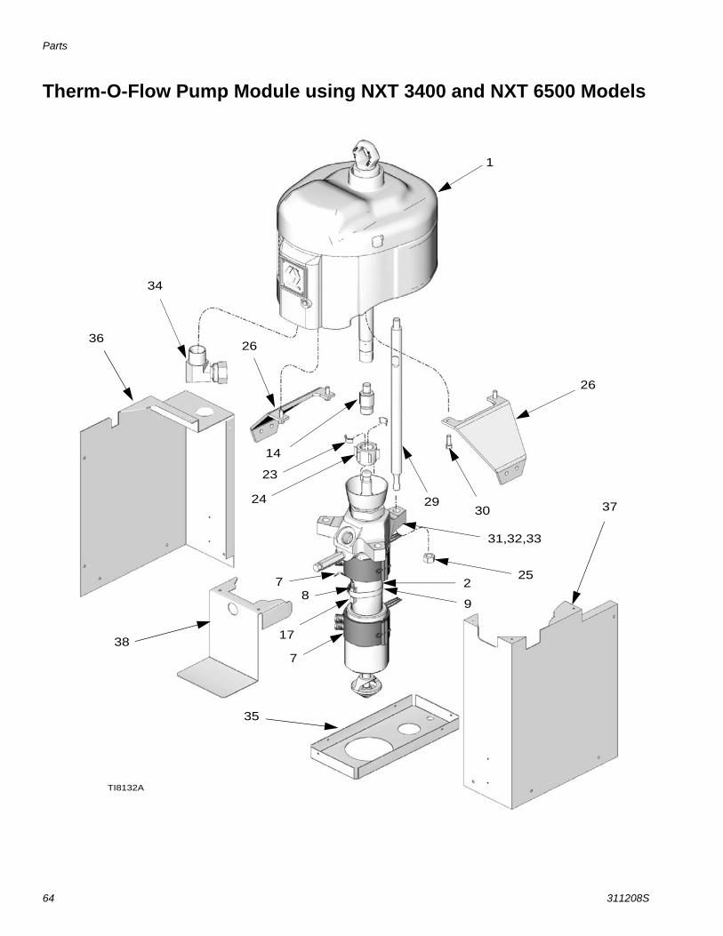
Parts
64 311208S
Therm-O-Flow Pump Module using NXT 3400 and NXT 6500 Models
1
2
30
26
26
2924
23
14
31,32,33
7
7
17
8
25
34
9
TI8132A
35
37
36
38
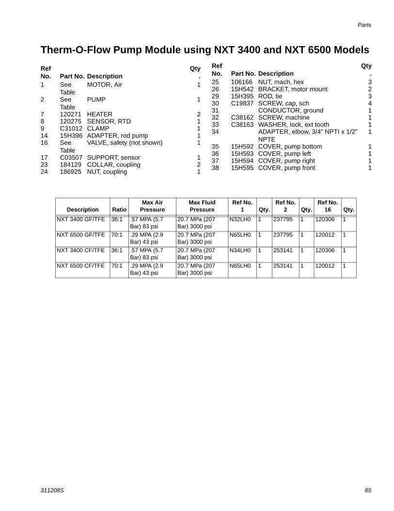
Parts
311208S 65
Therm-O-Flow Pump Module using NXT 3400 and NXT 6500 Models
Ref No. Part No. Description
Qty.
1 See Table
MOTOR, Air 1
2 See Table
PUMP 1
7 120271 HEATER 28 120275 SENSOR, RTD 19 C31012 CLAMP 114 15H396 ADAPTER, rod pump 116 See
TableVALVE, safety (not shown) 1
17 C03507 SUPPORT, sensor 123 184129 COLLAR, coupling 224 186925 NUT, coupling 1
25 106166 NUT, mach, hex 326 15H542 BRACKET, motor mount 229 15H395 ROD, tie 330 C19837 SCREW, cap, sch 431 CONDUCTOR, ground 132 C38162 SCREW, machine 133 C38163 WASHER, lock, ext tooth 134 ADAPTER, elbow, 3/4” NPTI x 1/2”
NPTE1
35 15H592 COVER, pump bottom 136 15H593 COVER, pump left 137 15H594 COVER, pump right 138 15H595 COVER, pump front 1
Ref No. Part No. Description
Qty.
Description RatioMax Air
PressureMax Fluid Pressure
Ref No. 1 Qty.
Ref No. 2 Qty.
Ref No. 16 Qty.
NXT 3400 GF/TFE 36:1 .57 MPA (5.7 Bar) 83 psi
20.7 MPa (207 Bar) 3000 psi
N32LH0 1 237795 1 120306 1
NXT 6500 GF/TFE 70:1 .29 MPA (2.9 Bar) 43 psi
20.7 MPa (207 Bar) 3000 psi
N65LH0 1 237795 1 120012 1
NXT 3400 CF/TFE 36:1 .57 MPA (5.7 Bar) 83 psi
20.7 MPa (207 Bar) 3000 psi
N34LH0 1 253141 1 120306 1
NXT 6500 CF/TFE 70:1 .29 MPA (2.9 Bar) 43 psi
20.7 MPa (207 Bar) 3000 psi
N65LH0 1 253141 1 120012 1
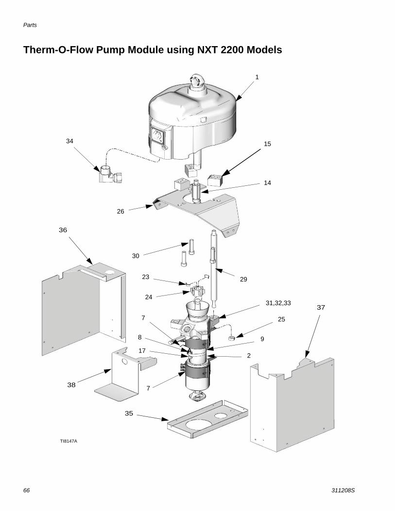
Parts
66 311208S
Therm-O-Flow Pump Module using NXT 2200 Models
1
2
30
26
29
24
23
14
31,32,33
7
7
17
8
25
34
9
TI8147A
15
35
36
37
38

Parts
311208S 67
Therm-O-Flow Pump Module using NXT 2200 Models
For NXT 2200 Models
Ref No. Part No. Description
Qty.
1 N22LH0 NXT 2200 AIR MOTOR 12 See
TablePUMP 1
7 120271 HEATER 28 120275 SENSOR, RTD 19 C31012 CLAMP 114 15H397 ADAPTER, rod pump 115 15H398 ADAPTER, motor mount 316 103347 VALVE, safety (not shown) 117 C03507 SUPPORT, sensor 123 184129 COLLAR, coupling 2
24 186925 NUT, coupling 125 106166 NUT, mach, hex 326 BRACKET, motor mount 129 15H395 ROD, tie 330 109211 SCREW, cap, sch 331 CONDUCTOR, ground 132 C38162 SCREW, machine 133 C38163 WASHER, lock, ext tooth 134 ADAPTER, elbow, 3/4” NPTI x 1/2”
NPTE1
35 15H592 COVER, pump bottom 136 15H593 COVER, pump left 137 15H594 COVER, pump right 138 15H595 COVER, pump front 1
Ref No. Part No. Description
Qty.
DescriptionRef No.
2 Max Air Pressure Max Fluid Pressure Qty.NXT 2200 GF/TFE 237795 0.7 MPA (7 Bar) 100 psi 15.9 MPa (159 Bar) 2300 psi 1NXT 2200 CF/TFE 237141 0.7 MPA (7 Bar) 100 psi 15.9 MPa (159 Bar) 2300 psi 1
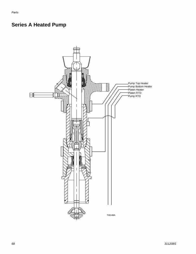
Parts
68 311208S
Series A Heated Pump
Pump Top HeaterPump Bottom HeaterPlaten HeaterPlaten RTDPump RTD
TI8148A
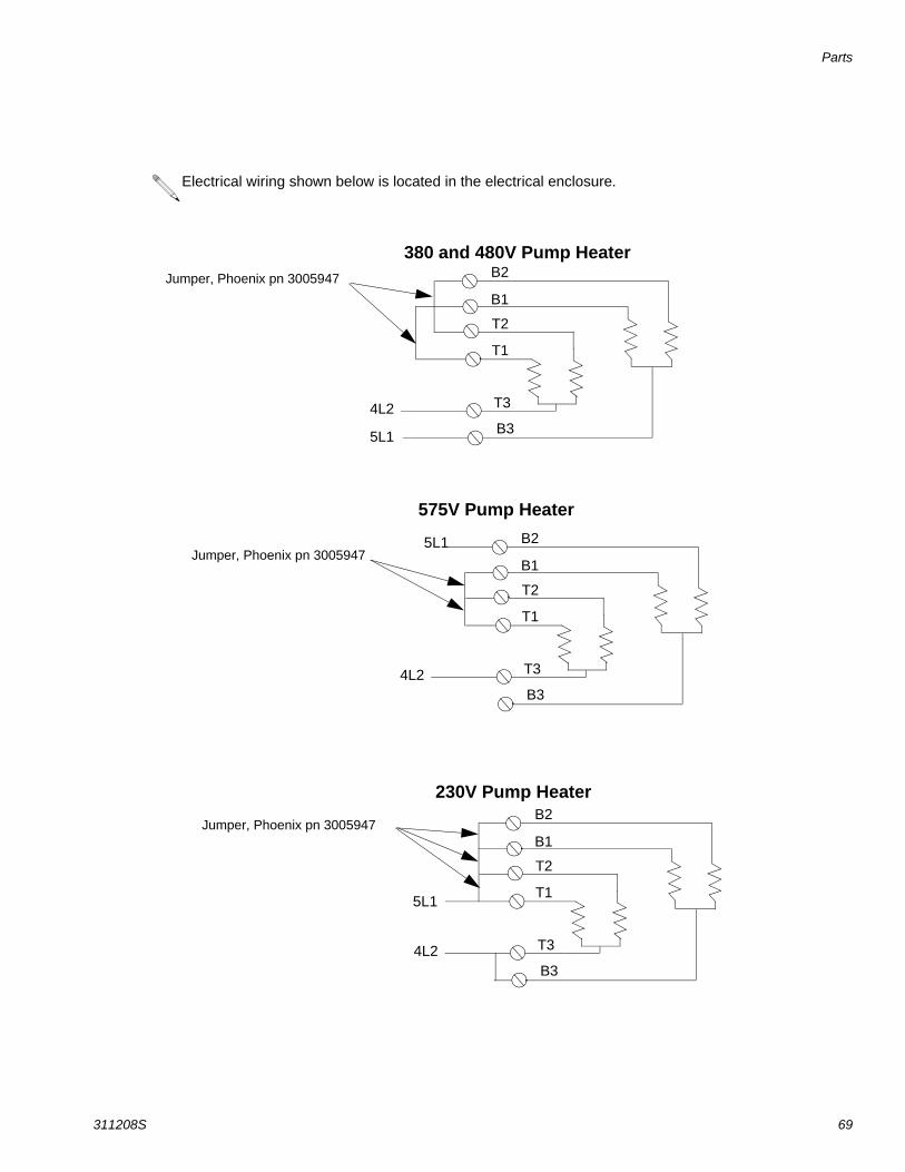
Parts
311208S 69
Jumper, Phoenix pn 3005947 B2
B1
T2
T1
T3
B34L2
5L1
380 and 480V Pump Heater
Jumper, Phoenix pn 3005947B2
B1
T2
T1
T3
B34L2
575V Pump Heater
Jumper, Phoenix pn 3005947B2
B1
T2
T1
T3
B34L2
230V Pump Heater
5L1
5L1
Electrical wiring shown below is located in the electrical enclosure.

Parts
70 311208S
Heated PlatensPart No, 253218 Heated Drum Platen, Mega-Flo (Code B - option A)
Part No, 253219 Heated Drum Platen, Standard Grid (Code B - Option B)
Part No. 253220 Drum Heated Platen, Smooth Bottom (no fin) (Code B - Option C)
Detail C Detail A Detail B
Standard Grid Plate Part No. 253219
Smooth Bottom No Grid Plate Part No. 253220
Mega-Flo Plate Part No. 253218
If one ring terminal see detail A. If two ring terminals see detail B
See detail C
6
7
8
9
10
27 28
14,15
11
12,13
5
25
26
24
2625
24
3
4
2
TIHeated Platens Modified
1
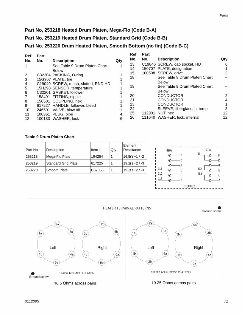
Parts
311208S 71
Part No, 253218 Heated Drum Platen, Mega-Flo (Code B-A)
Part No, 253219 Heated Drum Platen, Standard Grid (Code B-B)
Part No. 253220 Drum Heated Platen, Smooth Bottom (no fin) (Code B-C)
Ref No.
PartNo. Description Qty
1 See Table 9 Drum Platen Chart Below
1
2 C32204 PACKING, O-ring 13 15G967 PLATE, tire 14 C19049 SCREW, mach, slotted, RND HD 15 15H298 SENSOR, temperature 16 C32201 GASKET, follower 17 158491 FITTING, nipple 18 158581 COUPLING, hex 19 617227 HANDLE, follower, bleed 110 246501 VALVE, blow off 111 100361 PLUG, pipe 412 100133 WASHER, lock 6
13 C19846 SCREW, cap socket, HD 614 150707 PLATE, designation 115 100508 SCREW, drive 218 See Table 9 Drum Platen Chart
Below--
19 See Table 9 Drum Plated Chart Below
--
20 CONDUCTOR 221 CONDUCTOR 423 CONDUCTOR 124 SLEEVE, fiberglass, hi-temp 325 112901 NUT, hex 1226 111640 WASHER, lock, internal 12
Ref No.
PartNo. Description Qty
Table 9 Drum Platen Chart
Part No. Description Item 1 QtyElement Resistance
253218 Mega-Flo Plate 194254 1 16.5+1 / -2
253219 Standard Grid Plate 617225 1 19.2+2 / -3
253220 Smooth Plate C57358 1 19.2+2 / -3
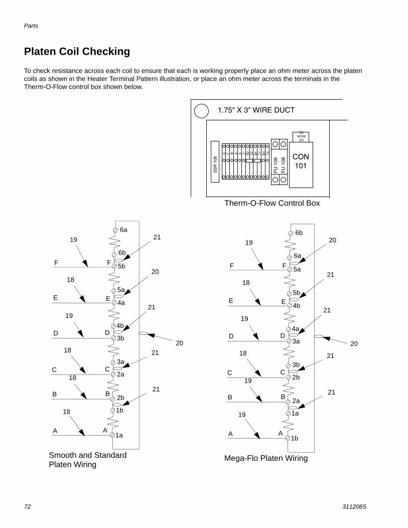
Parts
72 311208S
Platen Coil Checking
To check resistance across each coil to ensure that each is working properly place an ohm meter across the platen coils as shown in the Heater Terminal Pattern illustration, or place an ohm meter across the terminals in the Therm-O-Flow control box shown below.
A
B
C
D
E
F F
E
D
C
B
A1b
1a
2a
2b
3b
3a
4a
4b
5b
5a
6a
6b
Mega-Flo Platen Wiring
19
18
19
18
19
19
20
21
21
20
21
21
A
B
C
D
E
F F
E
D
C
B
A1a
1b
2b
2a
3a
3b
4b
4a
5a
5b
6b
6a
Smooth and Standard Platen Wiring
19
18
19
18
18
18
21
20
21
20
21
21
Therm-O-Flow Control Box

Parts
311208S 73
EasyKey Assembly, Part No. 253147
1
4
23
5
Back of EasyKey Assembly
TI7919A
TI7918A
Ref No. Part No. Description Qty1 LABEL, operations 12 DISPLAY, graphics 13 BOARD, circuit assembly 14 PLATE, blank 15 SCREW, pan head cross 4-40 4
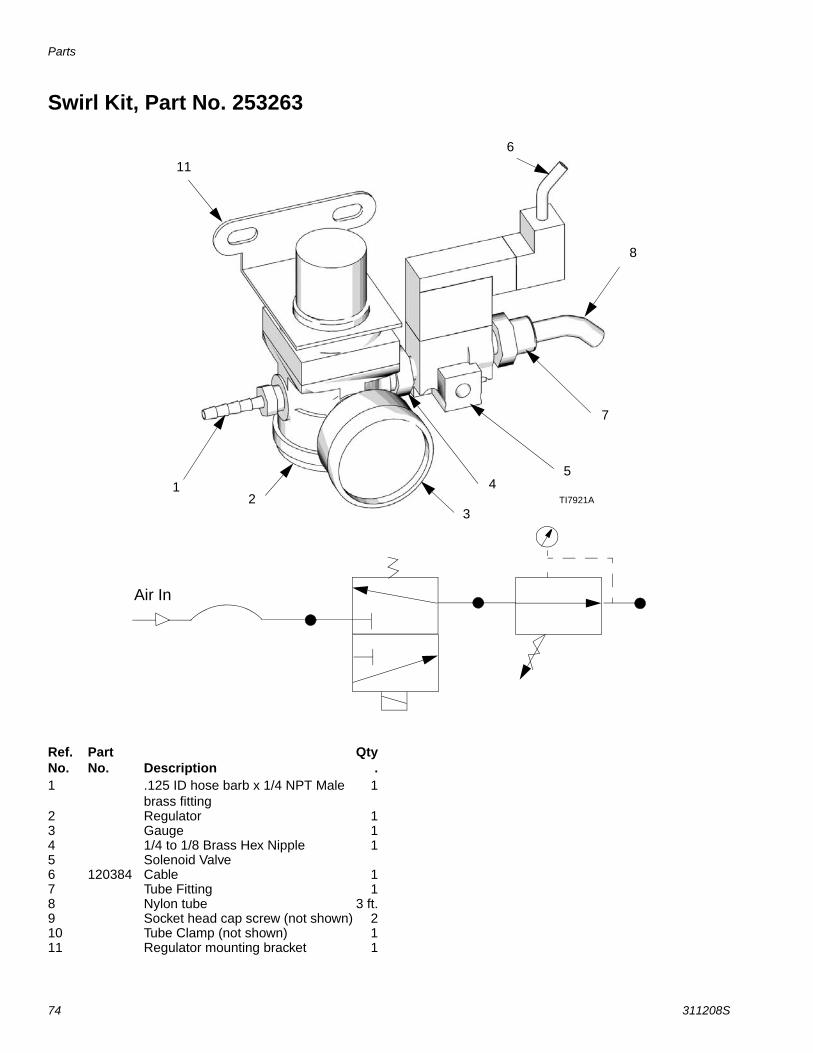
Parts
74 311208S
Swirl Kit, Part No. 253263
Air In
1
11
6
8
7
54
32 TI7921A
Ref.No.
PartNo. Description
Qty.
1 .125 ID hose barb x 1/4 NPT Male brass fitting
1
2 Regulator 13 Gauge 14 1/4 to 1/8 Brass Hex Nipple 15 Solenoid Valve6 120384 Cable 17 Tube Fitting 18 Nylon tube 3 ft.9 Socket head cap screw (not shown) 210 Tube Clamp (not shown) 111 Regulator mounting bracket 1
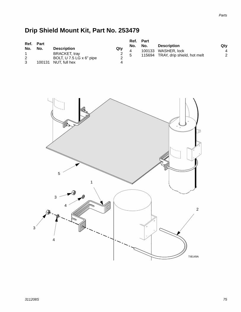
Parts
311208S 75
Drip Shield Mount Kit, Part No. 253479
Ref. No.
Part No. Description Qty
1 BRACKET, tray 22 BOLT, U 7.5 LG x 6” pipe 23 100131 NUT, full hex 4
4 100133 WASHER, lock 45 115694 TRAY, drip shield, hot melt 2
Ref. No.
Part No. Description Qty
5
3
4
2
1
3
4
TI8149A
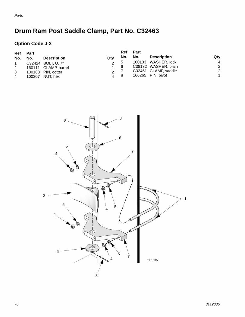
Parts
76 311208S
Drum Ram Post Saddle Clamp, Part No. C32463
Option Code J-3
Ref No.
PartNo. Description Qty
1 C32424 BOLT, U, 7” 22 160111 CLAMP, barrel 13 100103 PIN, cotter 24 100307 NUT, hex 4
5 100133 WASHER, lock 46 C38182 WASHER, plain 27 C32461 CLAMP, saddle 28 166265 PIN, pivot 1
Ref No.
PartNo. Description Qty
3
65
4
2
5
4
54
5
4
6
38
1
7
7
TI8150A

Parts
311208S 77
Heavy Duty Drum Band Clamp, Part No. 918395
Option Code J-2
Ref No.
PartNo. Description Qty
2 100101 SCREW, cap, hex HD 83 918421 CLAMP, back half assembly 14 918423 KIT, repair 15 617395 PIN, quick release 26 100133 WASHER, lock 8
7 C19200 WASHER, plain 88 617433 SPACER, drum clamp 89 617395 CLAMP, saddle 410 100131 NUT, full hex 811 C32424 BOLT, U 7” 4
Ref No.
PartNo. Description Qty
11 8,7,6,2 34
6,109
11
5
TI8151A
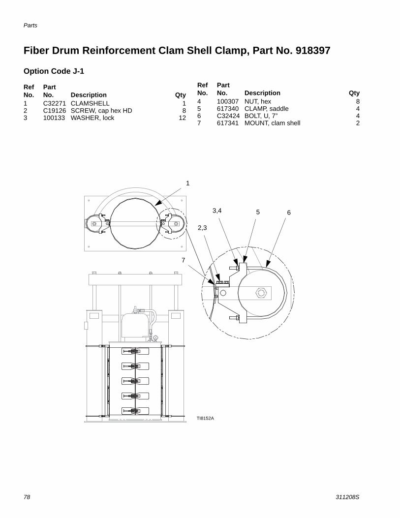
Parts
78 311208S
Fiber Drum Reinforcement Clam Shell Clamp, Part No. 918397
Option Code J-1
Ref No.
PartNo. Description Qty
1 C32271 CLAMSHELL 12 C19126 SCREW, cap hex HD 83 100133 WASHER, lock 12
4 100307 NUT, hex 85 617340 CLAMP, saddle 46 C32424 BOLT, U, 7” 47 617341 MOUNT, clam shell 2
Ref No.
PartNo. Description Qty
1
7
2,3
3,4 5 6
TI8152A

Parts
311208S 79
Vent Hood Accessory Kit for 6-1/2 In. Ram, Part No. 233559Ref No.
PartNo. Description Qty
1 VENT hood 12 112166 SCREW, cop sch 43 100016 WASHER, LOCK 45 C14038 LABEL, warning 1
Replacement Danger and Warning labels, tags, and cards are available at no cost.
3
2
1 5
TI8153A

Advanced Units
80 311208S
Advanced Units
Light Tower Kit (253547)The optional light tower kit has the following color and flashing lights to signal warnings and alarms. See FIG. 26.
Green denotes an active system where the pump will activate when material is needed.
Yellow denotes user attention is required.
Flashing yellow denotes a drum is empty (when equipped with proximity sensors).
Red denotes immediate user attention is required due to an alarm condition or interruption of material flow. The user should be aware that in the case of a motor error on a Single or Tandem system, or a Tandem system with both drums empty, heat may be applied to the platen and pump to allow for a drum change.
FIG. 26
TI8540A
FIG. 27
PC
B 3
00 E
asyK
ey B
oard
J7
1
2
34
5
3031
3041
30511271+24V
Terminal block
0
12
3
LT302
LightTower
1272
24 COM Terminal block
#18 Blue MTW TYP
TI8523A mod
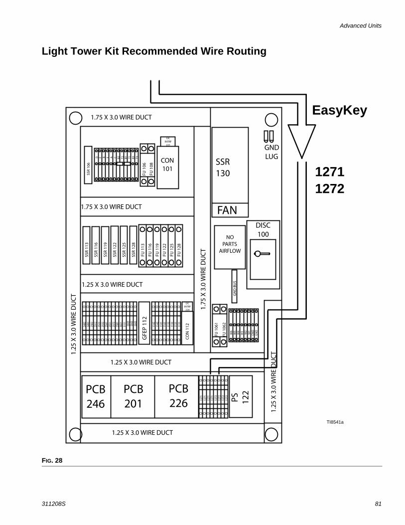
Advanced Units
311208S 81
Light Tower Kit Recommended Wire Routing
FIG. 28
EasyKey
12711272
TI8541a
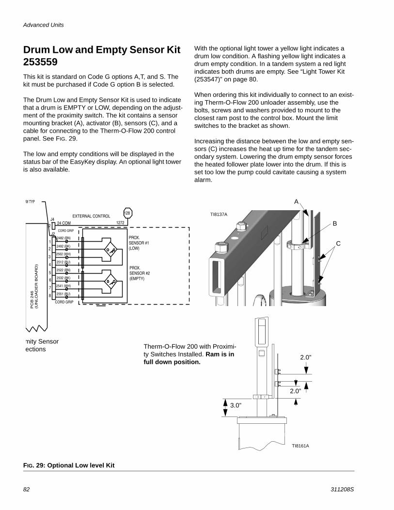
Advanced Units
82 311208S
Drum Low and Empty Sensor Kit 253559This kit is standard on Code G options A,T, and S. The kit must be purchased if Code G option B is selected.
The Drum Low and Empty Sensor Kit is used to indicate that a drum is EMPTY or LOW, depending on the adjust-ment of the proximity switch. The kit contains a sensor mounting bracket (A), activator (B), sensors (C), and a cable for connecting to the Therm-O-Flow 200 control panel. See FIG. 29.
The low and empty conditions will be displayed in the status bar of the EasyKey display. An optional light tower is also available.
With the optional light tower a yellow light indicates a drum low condition. A flashing yellow light indicates a drum empty condition. In a tandem system a red light indicates both drums are empty. See “Light Tower Kit (253547)” on page 80.
When ordering this kit individually to connect to an exist-ing Therm-O-Flow 200 unloader assembly, use the bolts, screws and washers provided to mount to the closest ram post to the control box. Mount the limit switches to the bracket as shown.
Increasing the distance between the low and empty sen-sors (C) increases the heat up time for the tandem sec-ondary system. Lowering the drum empty sensor forces the heated follower plate lower into the drum. If this is set too low the pump could cavitate causing a system alarm.
FIG. 29: Optional Low level Kit
Therm-O-Flow 200 with Proximi-ty Switches Installed. Ram is in full down position.
mity Sensor ections
B
A
C
TI8137A
3.0”
2.0”
TI8161A
2.0”
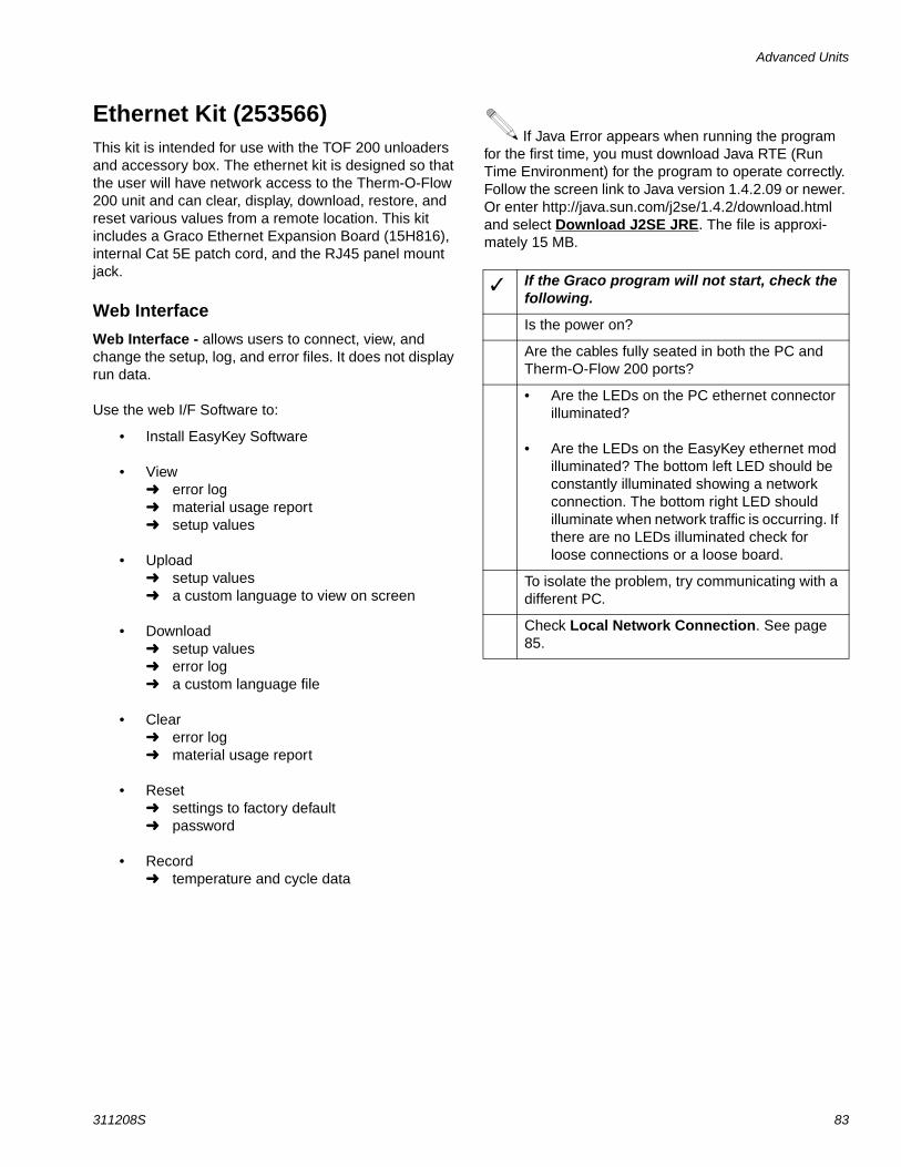
Advanced Units
311208S 83
Ethernet Kit (253566)This kit is intended for use with the TOF 200 unloaders and accessory box. The ethernet kit is designed so that the user will have network access to the Therm-O-Flow 200 unit and can clear, display, download, restore, and reset various values from a remote location. This kit includes a Graco Ethernet Expansion Board (15H816), internal Cat 5E patch cord, and the RJ45 panel mount jack.
Web InterfaceWeb Interface - allows users to connect, view, and change the setup, log, and error files. It does not display run data.
Use the web I/F Software to:
• Install EasyKey Software
• View error log material usage report setup values
• Upload setup values a custom language to view on screen
• Download setup values error log a custom language file
• Clear error log material usage report
• Reset settings to factory default password
• Record temperature and cycle data
If Java Error appears when running the program for the first time, you must download Java RTE (Run Time Environment) for the program to operate correctly. Follow the screen link to Java version 1.4.2.09 or newer. Or enter http://java.sun.com/j2se/1.4.2/download.html and select Download J2SE JRE. The file is approxi-mately 15 MB.
If the Graco program will not start, check the following.
Is the power on?
Are the cables fully seated in both the PC and Therm-O-Flow 200 ports?
• Are the LEDs on the PC ethernet connector illuminated?
• Are the LEDs on the EasyKey ethernet mod illuminated? The bottom left LED should be constantly illuminated showing a network connection. The bottom right LED should illuminate when network traffic is occurring. If there are no LEDs illuminated check for loose connections or a loose board.
To isolate the problem, try communicating with a different PC.
Check Local Network Connection. See page 85.
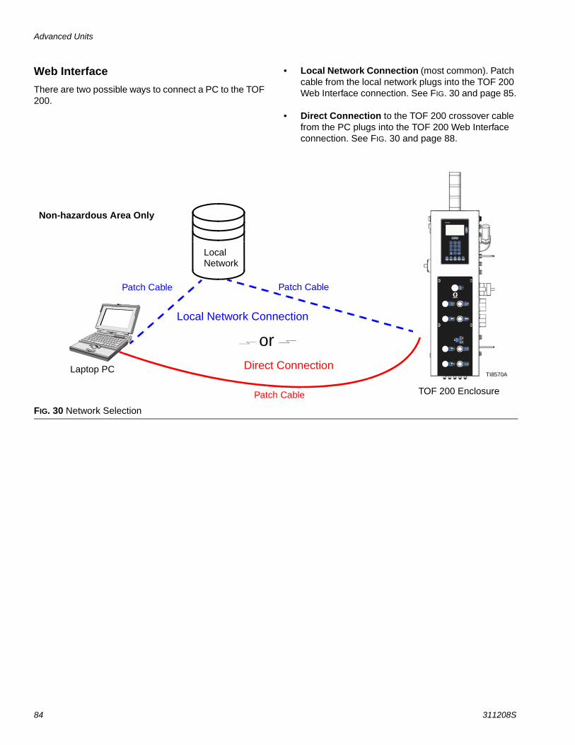
Advanced Units
84 311208S
Web InterfaceThere are two possible ways to connect a PC to the TOF 200.
• Local Network Connection (most common). Patch cable from the local network plugs into the TOF 200 Web Interface connection. See FIG. 30 and page 85.
• Direct Connection to the TOF 200 crossover cable from the PC plugs into the TOF 200 Web Interface connection. See FIG. 30 and page 88.
FIG. 30 Network Selection
Laptop PC
Non-hazardous Area Only
TOF 200 Enclosure
Patch Cable
or
Patch Cable
LocalNetwork
Direct Connection
Patch Cable
Local Network Connection
TI8570A
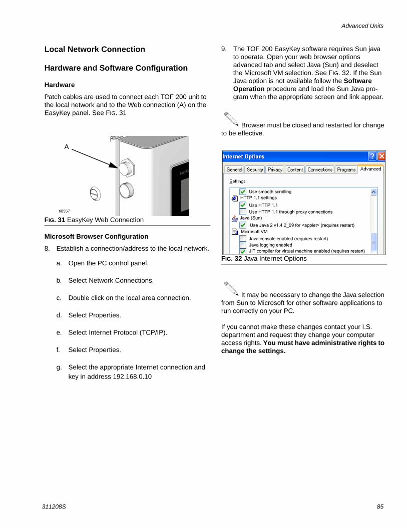
Advanced Units
311208S 85
Local Network Connection
Hardware and Software Configuration
Hardware
Patch cables are used to connect each TOF 200 unit to the local network and to the Web connection (A) on the EasyKey panel. See FIG. 31
Microsoft Browser Configuration
8. Establish a connection/address to the local network.
a. Open the PC control panel.
b. Select Network Connections.
c. Double click on the local area connection.
d. Select Properties.
e. Select Internet Protocol (TCP/IP).
f. Select Properties.
g. Select the appropriate Internet connection and key in address 192.168.0.10
9. The TOF 200 EasyKey software requires Sun java to operate. Open your web browser options advanced tab and select Java (Sun) and deselect the Microsoft VM selection. See FIG. 32. If the Sun Java option is not available follow the Software Operation procedure and load the Sun Java pro-gram when the appropriate screen and link appear.
Browser must be closed and restarted for change to be effective.
It may be necessary to change the Java selection from Sun to Microsoft for other software applications to run correctly on your PC.
If you cannot make these changes contact your I.S. department and request they change your computer access rights. You must have administrative rights to change the settings.
FIG. 31 EasyKey Web Connection
A
ti8557
FIG. 32 Java Internet Options
Use smooth scrollingHTTP 1.1 settings
Use HTTP 1.1
Use HTTP 1.1 through proxy connectionsJava (Sun)
Use Java 2 v1.4.2_09 for <applet> (requires restart)Microsoft VM
Java console enabled (requires restart)Java logging enabledJIT compiler for virtual machine enabled (requires restart)
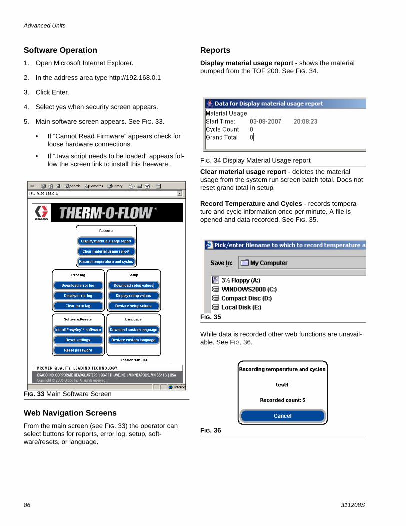
Advanced Units
86 311208S
Software Operation1. Open Microsoft Internet Explorer.
2. In the address area type http://192.168.0.1
3. Click Enter.
4. Select yes when security screen appears.
5. Main software screen appears. See FIG. 33.
• If “Cannot Read Firmware” appears check for loose hardware connections.
• If “Java script needs to be loaded” appears fol-low the screen link to install this freeware.
Web Navigation ScreensFrom the main screen (see FIG. 33) the operator can select buttons for reports, error log, setup, soft-ware/resets, or language.
ReportsDisplay material usage report - shows the material pumped from the TOF 200. See FIG. 34.
Clear material usage report - deletes the material usage from the system run screen batch total. Does not reset grand total in setup.
Record Temperature and Cycles - records tempera-ture and cycle information once per minute. A file is opened and data recorded. See FIG. 35.
While data is recorded other web functions are unavail-able. See FIG. 36.
FIG. 33 Main Software Screen
FIG. 34 Display Material Usage report
FIG. 35
FIG. 36

Advanced Units
311208S 87
Error Log
Download error log - downloads the error log to the PC.
Display error log - displays the number of alarms, date, time, recipe and what the error was. See FIG. 37.
Clear error log - deletes the errors from the display.
SetupDownload setup values - saves the TOF configuration to the PC. This file can be opened and edited using Microsoft Excel, or used to set up multiple systems.
Display setup values - indicates what values are currently being used for the system. Allows the operator to verify that the right values are being used. See FIG. 38.
Restore setup values - allows files to be uploaded and restored to the TOF.
Software/ResetsInstall EasyKey software - downloads the Graco provided software to the PC (approximately 5 minutes). Once complete the control panel will be reprogrammed from the EasyKey.
Reset settings - places system back to factory default mode.
Reset password - clears password if lost or forgotten.
LanguageDownload custom Language - saves the current system language to the PC. This file is opened and a custom language added to the B column of the Excel file. See FIG. 39.
Custom languages are limited to Ascii and Ascii extended characters and a maximum of 32 characters. Save the Excel file as a tab delineated file for uploading purposes.
Restore custom language - allows the custom lan-guage file to be uploaded to the TOF.
Advanced ConfigurationTo change IP settings use the freeware configuration program available from www.lantronix.com/device-net-working/utilities-tools/device-installer.html.
FIG. 37 Display Error Log
FIG. 38 Display Set up
FIG. 39 Download Custom Language

Advanced Units
88 311208S
Ethernet Kit InstallationGraco Kit 253566 is required for this connection.
Kit Installation1. Power the Therm-O-Flow system off and disconnect
power source.
2. Open the control panel door.
3. Remove the EasyKey Display shield.
4. Locate the 10 pin Expansion Connector J9 (A) on the lower right of the EasyKey Display Assembly 249480 (B). See FIG. 41.
5. Plug the Ethernet Assembly 249183 (C) into J9 making sure the RJ45 connector is oriented down. See FIG. 42 and FIG. 43.
6. Secure the Ethernet Assembly 249183 (C) to the EasyKey Display 249480 (B) using the hardware provided.
7. Remove plug (D) covering Ethernet opening at the upper right corner of the Control Panel. See FIG. 40.
8. Secure Bulkhead Receptacle in the Ethernet open-ing at the upper right corner of the Control Panel.
9. Connect one end of the Ethernet cable to Ethernet Assembly 249183 (C).
10. Replace EasyKey Display shield connecting ground terminal from Ethernet Bulkhead connector to upper right stud.
11. Connect the other end of the Ethernet cable to the Ethernet bulkhead receptacle.
12. Close the Control Panel door.
Changing Network Configuration1. Connect PC to ethernet connection on EasyKey
with the crossover cable.
2. Connect network to PC with DeviceInstaller.
3. Run DeviceInstaller program.
A freeware configuration program is available from www.lantronix.com/device-networking/utili-ties-tools/device-installer.html
4. To change IP Address from Default setting 192.168.0.1
a. Run DeviceInstaller
b. Click “Search”
c. Select device
d. Click “Assign IP”
Select and assign specific IP address.
i. Input address
ii. Enter subnet mask 255.255.255.0
iii. Click “Assign” (unit is programmed and will now reboot)
iv. Click “Finish”
v. Close/Exit DeviceInstaller
Alternate method via telnet and port 9999.
Serial Port Setup
Kit is pre-programmed with these settings.
- 57,600 baud, 8-bit, no parity, 1-stop bit.
Do not operate Therm-O-Flow 200 with equipment enclosure doors/covers open. Disconnect power source before servicing or electrically wiring.
FIG. 40 RJ45 Bulkhead Connector Installation
D
ti8557
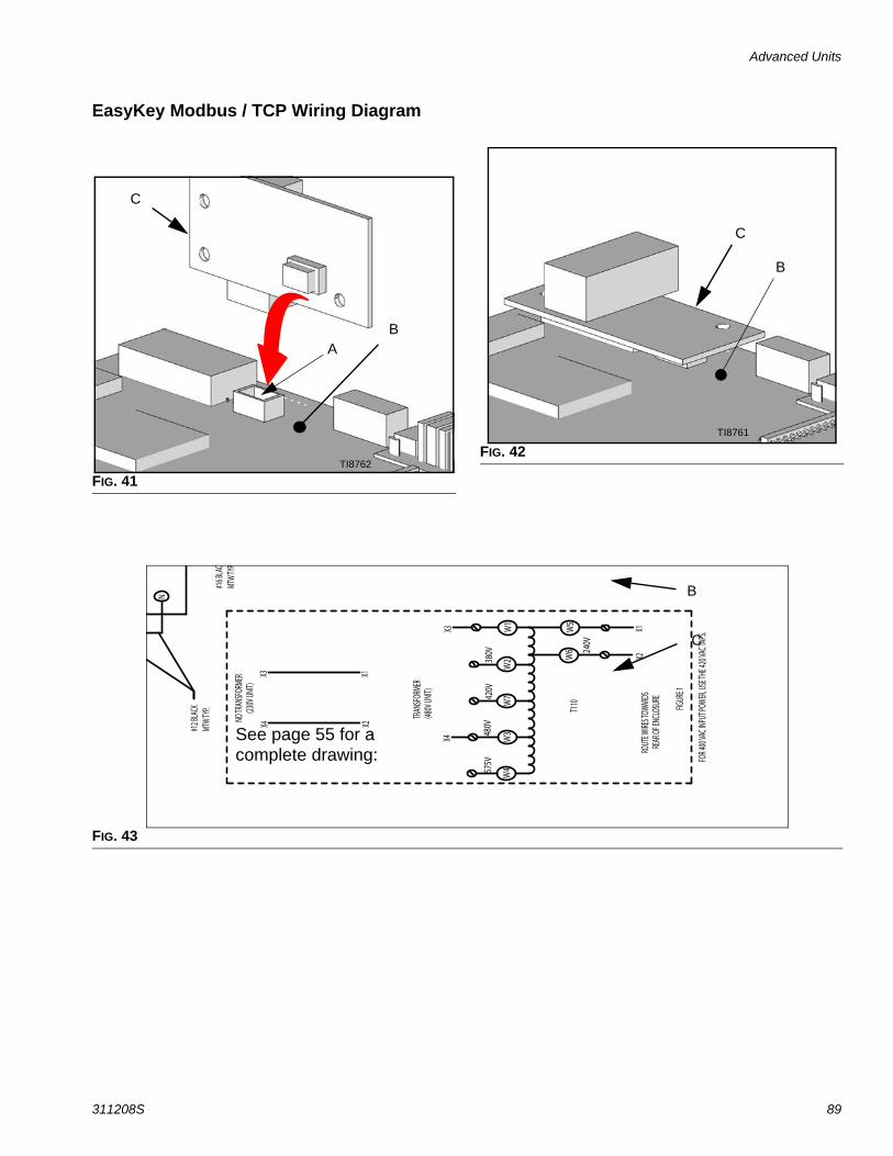
Advanced Units
311208S 89
EasyKey Modbus / TCP Wiring Diagram
FIG. 41
AB
C
TI8762FIG. 42
C
B
TI8761
FIG. 43
N
#12 B
LACK
MTW
TYP.
#16 B
LAC
MTW
TYP.
W4
W3
W2
W1
575V
480V
380V
W5
W6 24
0V
X4X3
X2X1
TRAN
SFORM
ER(48
0V UN
IT)
NO TR
ANSFO
RMER
(230V
UNIT)
X4X3
X2X1
FIGUR
E 1
T110
ROUT
E WIRE
S TOW
ARDS
RE
AR OF
ENCL
OSUR
E
W742
0V
FOR 4
00 VA
C INP
UT PO
WER, U
SE TH
E 420
VAC T
APS.
See page 55 for a complete drawing:
C
B
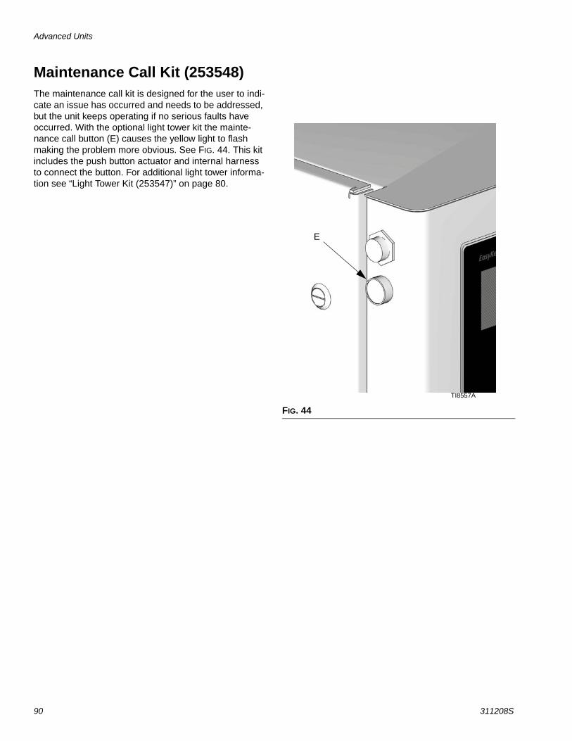
Advanced Units
90 311208S
Maintenance Call Kit (253548)The maintenance call kit is designed for the user to indi-cate an issue has occurred and needs to be addressed, but the unit keeps operating if no serious faults have occurred. With the optional light tower kit the mainte-nance call button (E) causes the yellow light to flash making the problem more obvious. See FIG. 44. This kit includes the push button actuator and internal harness to connect the button. For additional light tower informa-tion see “Light Tower Kit (253547)” on page 80.
FIG. 44
TI8557A
E
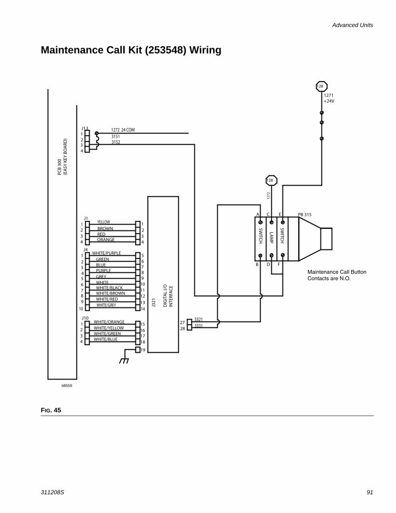
Advanced Units
311208S 91
Maintenance Call Kit (253548) Wiring
FIG. 45
PCB
300
(EA
SY K
EY B
OA
RD)
1 2 3 4 5 6 7 8 9
2 3
2 3 4
7 8 9
1 2 3 4
1
4
5 6
10 11 12
13
15 16 17 18
J1
J4
J10
J321
D
IGIT
AL
I/O
IN
TERF
AC
E
BROWN RED ORANGE
WHITE/PURPLE
GREEN BLUE PURPLE GREY WHITE WHITE/BLACK WHITE/BROWN WHITE/RED
WHITE/ORANGE
WHITE/YELLOW WHITE/GREEN WHITE/BLUE
128
1271 +24V
1272
1 2 3 4
J13
SWITC
H
LAM
P
SWITC
H
A
B
C
D
E
F
PB 315
1
28 27
3321 3331
10 14 WHITE/GREY
YELLOW
1272 24 COM
128
3151 3152
19
Maintenance Call Button Contacts are N.O.
ti8559
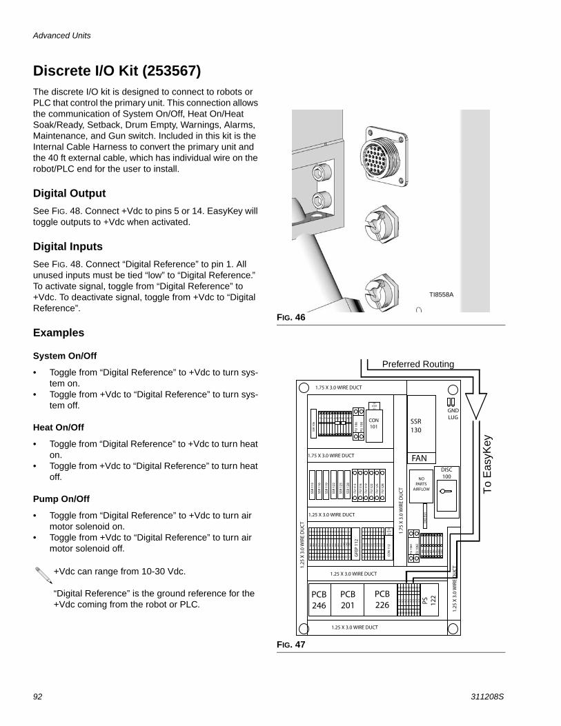
Advanced Units
92 311208S
Discrete I/O Kit (253567)The discrete I/O kit is designed to connect to robots or PLC that control the primary unit. This connection allows the communication of System On/Off, Heat On/Heat Soak/Ready, Setback, Drum Empty, Warnings, Alarms, Maintenance, and Gun switch. Included in this kit is the Internal Cable Harness to convert the primary unit and the 40 ft external cable, which has individual wire on the robot/PLC end for the user to install.
Digital OutputSee FIG. 48. Connect +Vdc to pins 5 or 14. EasyKey will toggle outputs to +Vdc when activated.
Digital InputsSee FIG. 48. Connect “Digital Reference” to pin 1. All unused inputs must be tied “low” to “Digital Reference.” To activate signal, toggle from “Digital Reference” to +Vdc. To deactivate signal, toggle from +Vdc to “Digital Reference”.
Examples
System On/Off
• Toggle from “Digital Reference” to +Vdc to turn sys-tem on.
• Toggle from +Vdc to “Digital Reference” to turn sys-tem off.
Heat On/Off
• Toggle from “Digital Reference” to +Vdc to turn heat on.
• Toggle from +Vdc to “Digital Reference” to turn heat off.
Pump On/Off
• Toggle from “Digital Reference” to +Vdc to turn air motor solenoid on.
• Toggle from +Vdc to “Digital Reference” to turn air motor solenoid off.
+Vdc can range from 10-30 Vdc.
“Digital Reference” is the ground reference for the +Vdc coming from the robot or PLC.
FIG. 46
FIG. 47
TI8558A
Preferred Routing
To
Eas
yKey
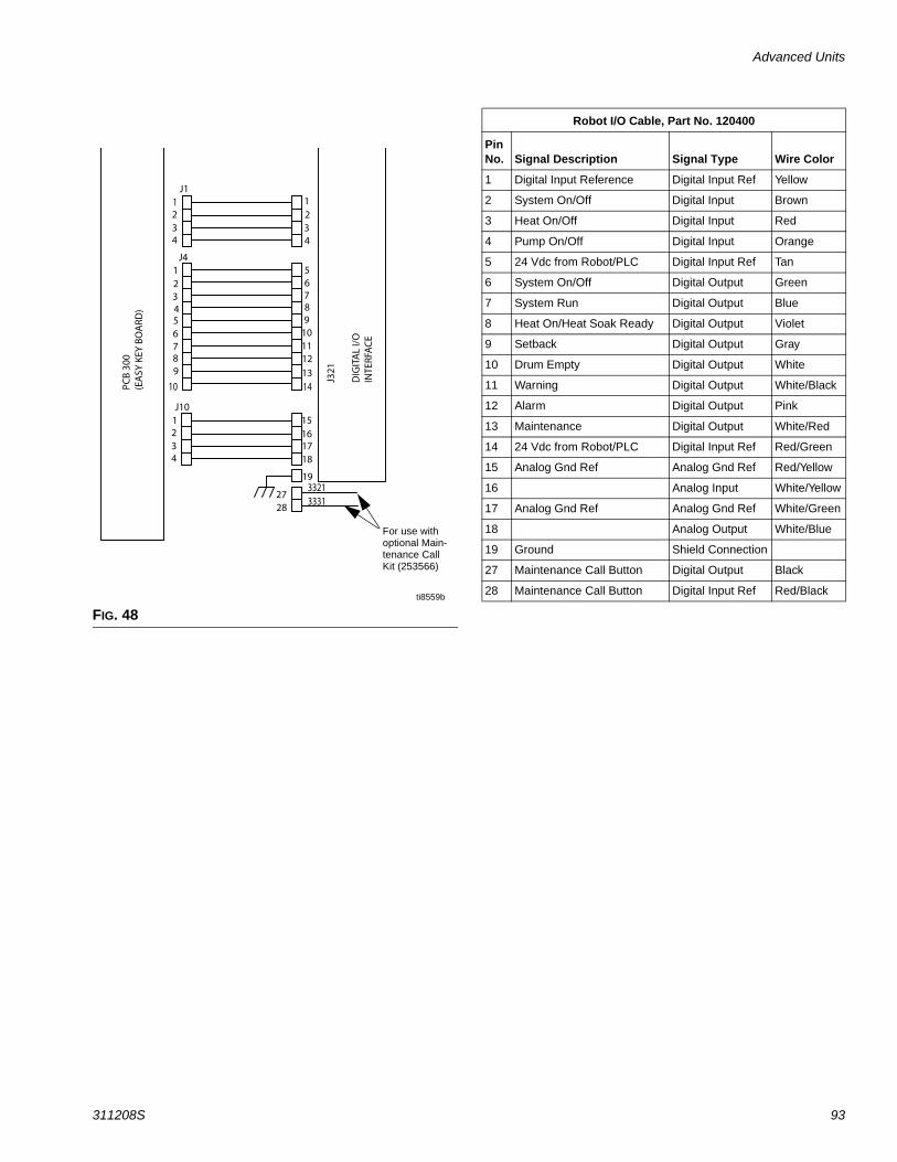
Advanced Units
311208S 93
FIG. 48ti8559b
For use with optional Main-tenance Call Kit (253566)
Robot I/O Cable, Part No. 120400
Pin No. Signal Description Signal Type Wire Color
1 Digital Input Reference Digital Input Ref Yellow
2 System On/Off Digital Input Brown
3 Heat On/Off Digital Input Red
4 Pump On/Off Digital Input Orange
5 24 Vdc from Robot/PLC Digital Input Ref Tan
6 System On/Off Digital Output Green
7 System Run Digital Output Blue
8 Heat On/Heat Soak Ready Digital Output Violet
9 Setback Digital Output Gray
10 Drum Empty Digital Output White
11 Warning Digital Output White/Black
12 Alarm Digital Output Pink
13 Maintenance Digital Output White/Red
14 24 Vdc from Robot/PLC Digital Input Ref Red/Green
15 Analog Gnd Ref Analog Gnd Ref Red/Yellow
16 Analog Input White/Yellow
17 Analog Gnd Ref Analog Gnd Ref White/Green
18 Analog Output White/Blue
19 Ground Shield Connection
27 Maintenance Call Button Digital Output Black
28 Maintenance Call Button Digital Input Ref Red/Black
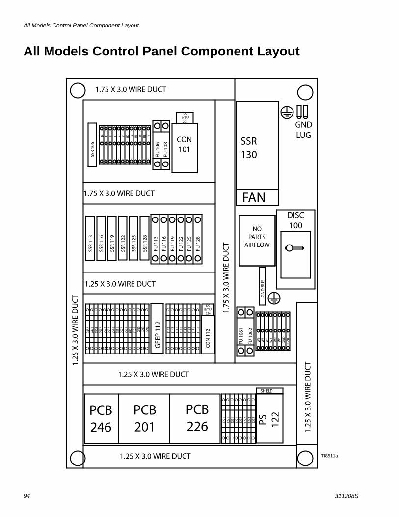
All Models Control Panel Component Layout
94 311208S
All Models Control Panel Component Layout
TI8511a
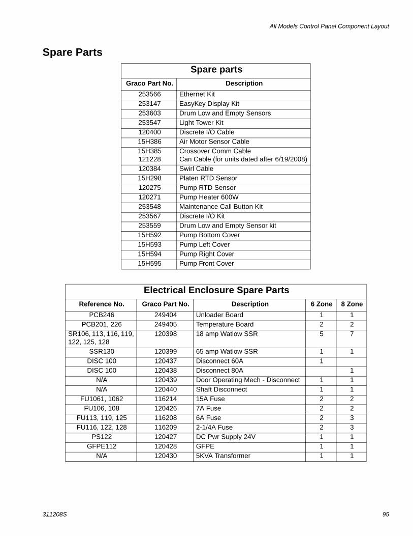
All Models Control Panel Component Layout
311208S 95
Spare PartsSpare parts
Graco Part No. Description253566 Ethernet Kit253147 EasyKey Display Kit253603 Drum Low and Empty Sensors253547 Light Tower Kit120400 Discrete I/O Cable15H386 Air Motor Sensor Cable15H385121228
Crossover Comm Cable Can Cable (for units dated after 6/19/2008)
120384 Swirl Cable15H298 Platen RTD Sensor120275 Pump RTD Sensor120271 Pump Heater 600W253548 Maintenance Call Button Kit253567 Discrete I/O Kit253559 Drum Low and Empty Sensor kit15H592 Pump Bottom Cover15H593 Pump Left Cover15H594 Pump Right Cover15H595 Pump Front Cover
Electrical Enclosure Spare PartsReference No. Graco Part No. Description 6 Zone 8 Zone
PCB246 249404 Unloader Board 1 1PCB201, 226 249405 Temperature Board 2 2
SR106, 113, 116, 119, 122, 125, 128
120398 18 amp Watlow SSR 5 7
SSR130 120399 65 amp Watlow SSR 1 1DISC 100 120437 Disconnect 60A 1DISC 100 120438 Disconnect 80A 1
N/A 120439 Door Operating Mech - Disconnect 1 1N/A 120440 Shaft Disconnect 1 1
FU1061, 1062 116214 15A Fuse 2 2FU106, 108 120426 7A Fuse 2 2
FU113, 119, 125 116208 6A Fuse 2 3FU116, 122, 128 116209 2-1/4A Fuse 2 3
PS122 120427 DC Pwr Supply 24V 1 1GFPE112 120428 GFPE 1 1
N/A 120430 5KVA Transformer 1 1
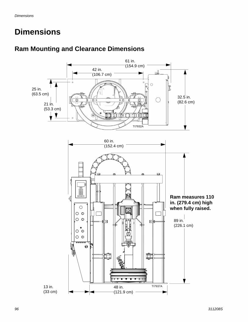
Dimensions
96 311208S
Dimensions
Ram Mounting and Clearance Dimensions
61 in.(154.9 cm)
42 in.(106.7 cm)
25 in.(63.5 cm)
21 in.(53.3 cm)
32.5 in.(82.6 cm)
60 in.(152.4 cm)
89 in.(226.1 cm)
48 in.(121.9 cm)
13 in.(33 cm)
Ram measures 110 in. (279.4 cm) high when fully raised.
TI7932A
TI7937A

Technical Data
311208S 97
Technical Data
Displacement pump effective area . . . . . . . . . . . . . . . . . . 1.24 in.2 (8 cm2)Volume per cycle . . . . . . . . . . . . . . . . . . . . . . . . . . . . . . . 11.7 in.3 (192 cm3)Pump cycles per 1 gal. (3.8 liters) . . . . . . . . . . . . . . . . . . 21
Maximum fluid working pressureNXT 2200. . . . . . . . . . . . . . . . . . . . . . . . . . . . . . . . . . 2300 psi (15.9 MPa, 159 bar)NXT 3400. . . . . . . . . . . . . . . . . . . . . . . . . . . . . . . . . . 3000 psi (20.7 MPa, 207 bar)NXT 6500. . . . . . . . . . . . . . . . . . . . . . . . . . . . . . . . . . 3000 psi (20.7 MPa, 207 bar)
Maximum air input pressure (Ram) . . . . . . . . . . . . . . . . . 125 psi (0.85 MPa, 8.5 bar)
Maximum air input pressure (Pumps). . . . . . . . . . . . . . . .NXT 2200. . . . . . . . . . . . . . . . . . . . . . . . . . . . . . . . . . 100 psi (0.7 MPa, 7 bar)NXT 3400. . . . . . . . . . . . . . . . . . . . . . . . . . . . . . . . . . 82 psi (0.57 MPa, 5.7 bar)NXT 6500. . . . . . . . . . . . . . . . . . . . . . . . . . . . . . . . . . 43 psi (0.29 MPa, 2.9 bar)
Maximum pump operating temperature . . . . . . . . . . . . . . 400°F (204°C)
Air motor piston effective area
NXT 2200. . . . . . . . . . . . . . . . . . . . . . . . . . . . . . . . . . 28.3 in.2 (182 cm2)
NXT 3400. . . . . . . . . . . . . . . . . . . . . . . . . . . . . . . . . . 44.2 in.2 (285 cm2)
NXT 6500. . . . . . . . . . . . . . . . . . . . . . . . . . . . . . . . . . 84.5 in.2 (545 cm2)Air inlet size . . . . . . . . . . . . . . . . . . . . . . . . . . . . . . . . . . . 1/2 npsm(f)Pump fluid outlet size . . . . . . . . . . . . . . . . . . . . . . . . . . . . 1 in. npt(f)Wetted parts . . . . . . . . . . . . . . . . . . . . . . . . . . . . . . . . . . . Carbon steel; brass; chrome, zinc, and nickel plating; 304,
316, 440, and 17-4 PH grades of stainless steel; alloy steel; ductile iron; PTFE
Weight . . . . . . . . . . . . . . . . . . . . . . . . . . . . . . . . . . . . . . . 1200 lb (545 kg)Displacement pump weight . . . . . . . . . . . . . . . . . . . . . . . 81 lb (37 kg)Instruction Manuals
Heated Hoses . . . . . . . . . . . . . . . . . . . . . . . . . . . . . . 309160Wiper Kits. . . . . . . . . . . . . . . . . . . . . . . . . . . . . . . . . . 309196Bare Displacement Pump Lower . . . . . . . . . . . . . . . . 3085706.5 in. (165 mm) Global Ram Module . . . . . . . . . . . . 310523
Power requirementsCompressed air . . . . . . . . . . . . . . . . . . . . . . . . . . . . . 25-50 scfm (typical)Voltage (as selected) . . . . . . . . . . . . . . . . . . . . . . . . . 220/240 V, 3-phase, 50/60 Hz
380/400 V, 3-phase, 50/60 Hz470/490 V, 3-phase, 50/60 Hz575 V, 3-phase, 50/60 Hz
Peak consumption*with standard melt grid. . . . . . . . . . . . . . . . . . . . . . . . 24.5 kVawith Mega-Flo melt grid . . . . . . . . . . . . . . . . . . . . . . . 27.5 kVawith smooth melt grid . . . . . . . . . . . . . . . . . . . . . . . . . 24.5 kVa
* Includes drum melt grid, pump, and a 5 kVa transformer for the 230 V hoses and accessories.

All written and visual data contained in this document reflects the latest product information available at the time of publication. Graco reserves the right to make changes at any time without notice.
For patent information, see www.graco.com/patents.
Original instructions. This manual contains English. MM 311208
Graco Headquarters: MinneapolisInternational Offices: Belgium, China, Japan, Korea
GRACO INC. AND SUBSIDIARIES • P.O. BOX 1441 • MINNEAPOLIS MN 55440-1441 • USACopyright 2006, Graco Inc. All Graco manufacturing locations are registered to ISO 9001.
www.graco.comRevision S, July 2017
Graco Standard Warranty Graco warrants all equipment referenced in this document which is manufactured by Graco and bearing its name to be free from defects in material and workmanship on the date of sale to the original purchaser for use. With the exception of any special, extended, or limited warranty published by Graco, Graco will, for a period of twelve months from the date of sale, repair or replace any part of the equipment determined by Graco to be defective. This warranty applies only when the equipment is installed, operated and maintained in accordance with Graco's written recommendations.
This warranty does not cover, and Graco shall not be liable for general wear and tear, or any malfunction, damage or wear caused by faulty installation, misapplication, abrasion, corrosion, inadequate or improper maintenance, negligence, accident, tampering, or substitution of non-Graco component parts. Nor shall Graco be liable for malfunction, damage or wear caused by the incompatibility of Graco equipment with structures, accessories, equipment or materials not supplied by Graco, or the improper design, manufacture, installation, operation or maintenance of structures, accessories, equipment or materials not supplied by Graco.
This warranty is conditioned upon the prepaid return of the equipment claimed to be defective to an authorized Graco distributor for verification of the claimed defect. If the claimed defect is verified, Graco will repair or replace free of charge any defective parts. The equipment will be returned to the original purchaser transportation prepaid. If inspection of the equipment does not disclose any defect in material or workmanship, repairs will be made at a reasonable charge, which charges may include the costs of parts, labor, and transportation.
THIS WARRANTY IS EXCLUSIVE, AND IS IN LIEU OF ANY OTHER WARRANTIES, EXPRESS OR IMPLIED, INCLUDING BUT NOT LIMITED TO WARRANTY OF MERCHANTABILITY OR WARRANTY OF FITNESS FOR A PARTICULAR PURPOSE.
Graco's sole obligation and buyer's sole remedy for any breach of warranty shall be as set forth above. The buyer agrees that no other remedy (including, but not limited to, incidental or consequential damages for lost profits, lost sales, injury to person or property, or any other incidental or consequential loss) shall be available. Any action for breach of warranty must be brought within two (2) years of the date of sale.
GRACO MAKES NO WARRANTY, AND DISCLAIMS ALL IMPLIED WARRANTIES OF MERCHANTABILITY AND FITNESS FOR A PARTICULAR PURPOSE, IN CONNECTION WITH ACCESSORIES, EQUIPMENT, MATERIALS OR COMPONENTS SOLD BUT NOT MANUFACTURED BY GRACO. These items sold, but not manufactured by Graco (such as electric motors, switches, hose, etc.), are subject to the warranty, if any, of their manufacturer. Graco will provide purchaser with reasonable assistance in making any claim for breach of these warranties.
In no event will Graco be liable for indirect, incidental, special or consequential damages resulting from Graco supplying equipment hereunder, or the furnishing, performance, or use of any products or other goods sold hereto, whether due to a breach of contract, breach of warranty, the negligence of Graco, or otherwise.
FOR GRACO CANADA CUSTOMERSThe parties acknowledge that they have required that the present document, as well as all documents, notices and legal proceedings entered into, given or instituted pursuant hereto or relating directly or indirectly hereto, be drawn up in English. Les parties reconnaissent avoir convenu que la rédaction du présente document sera en Anglais, ainsi que tous documents, avis et procédures judiciaires exécutés, donnés ou intentés à la suite de ou en rapport, directement ou indirectement, avec les procedures concernées.
Graco InformationFor the latest information about Graco products, visit www.graco.com.
For patent information, see www.graco.com/patents.
TO PLACE AN ORDER, contact your Graco distributor or call to identify the nearest distributor.Phone: 612-623-6921 or Toll Free: 1-800-328-0211 Fax: 612-378-3505


![Therm L1 [Basics]](https://static.fdocuments.in/doc/165x107/577d276d1a28ab4e1ea3e5da/therm-l1-basics.jpg)