2.0 Shear Stress
26
Dr. Nauman KHURRAM Dr. Nauman KHURRAM Assistant Professor Department of Civil Engineering Structural Mechanics (CE- 312) Shear Stress in Thin Walled Members UNIVERSITY OF ENGINEERING & TECHNOLOGY LAHORE
-
Upload
usman-afzal -
Category
Documents
-
view
25 -
download
5
description
n:N
Transcript of 2.0 Shear Stress
Dr. Nauman KHURRAM
Dr. Nauman KHURRAM
Assistant Professor
Department of Civil Engineering
Structural Mechanics (CE- 312) Shear Stress in Thin Walled Members
UNIVERSITY OF ENGINEERING &
TECHNOLOGY LAHORE

Dr. Nauman KHURRAM Dr. Nauman KHURRAM
Review of Shear Formula
2
There are two types of the stresses that act over the
transversal section of a beam subjected bending
1. Bending (flexure) stresses which act parallel to the
longitudinal axes and vary directly with bending moment.
2. Shear stresses (which act perpendicular to the longitudinal
axes of the member) that vary directly with shear.
shear force (V) is the sum of all vertical components of the
external load acting on either side of section
I
yM .
Ib
YAV

Dr. Nauman KHURRAM Dr. Nauman KHURRAM
3
DERIVATION OF SHEAR FORMULA
Assumptions
1. Material is homogeneous and all the stresses are within
the elastic range (Hooks law implies).
2. Shear stresses are uniformly distributed over the entire
cross-section.
3. The formula is being derived for the rectangular cross
section but it may also be applied to any other cross
section with a plane of symmetry to calculate the
approximate value of shearing stress.
When a beam is subjected to
transversal loading the, shear
stress produced in longitudinal
axes tends to slide the grains
with respect to each other.

Dr. Nauman KHURRAM Dr. Nauman KHURRAM
4
Let consider a differential segment of thickness dx along the
length of a beam of rectangular cross-section (bxh). The
beam is subjected to transversal loading as shown in figure.
Assuming that due to applied
loading. V1=V, M1=M and
V2=V+ΔV, M2=M+ΔM are the
resisting shear force and bending
moment acting on the either side of
the differential segment dx.

Dr. Nauman KHURRAM Dr. Nauman KHURRAM
5
Considering M2 > M1 and thus compression forces (produced
by these bending moment) F2 > F1. since no force is acting
on the top or sides, dF is balancing force acting at the bottom
of the any arbitrary layer (p - p1).
Bending stress above the layer P-P1 Force diagram
Dr. Nauman KHURRAM Dr. Nauman KHURRAM
6
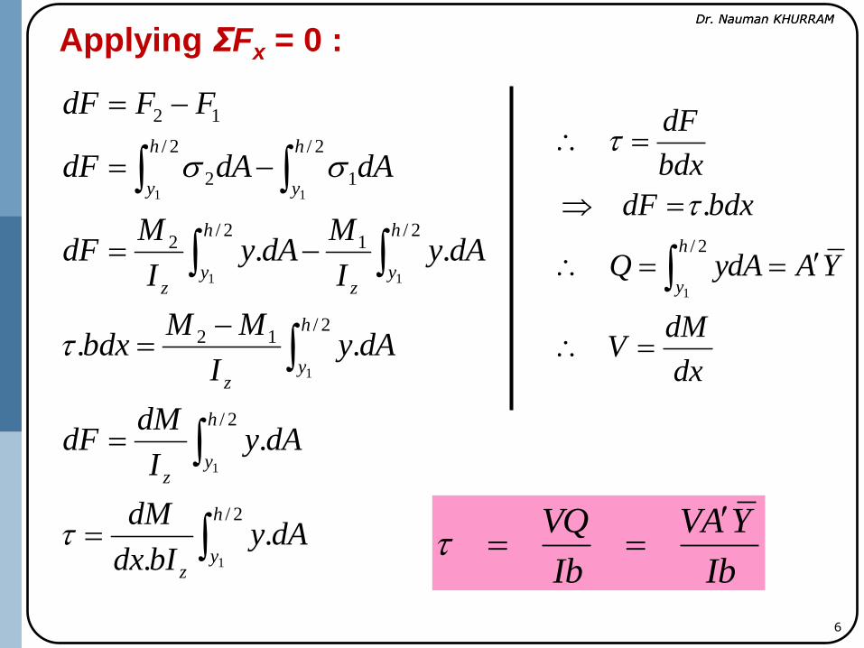
Applying ΣFx = 0 :
2/
2/
2/12
2/1
2/2
2/
1
2/
2
12
1
1
1
11
11
..
.
..
..
h
yz
h
yz
h
yz
h
yz
h
yz
h
y
h
y
dAybIdx
dM
dAyI
dMdF
dAyI
MMbdx
dAyI
MdAy
I
MdF
dAdAdF
FFdF
dx
dMV
YAydAQ
bdxdF
bdx
dF
h
y
2/
1
.
Ib
YAV
Ib
VQ
Dr. Nauman KHURRAM Dr. Nauman KHURRAM
7
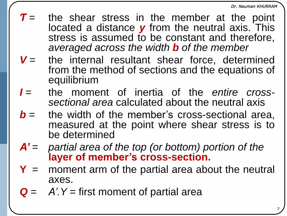
Ƭ = the shear stress in the member at the point located a distance y from the neutral axis. This stress is assumed to be constant and therefore, averaged across the width b of the member
V = the internal resultant shear force, determined from the method of sections and the equations of equilibrium
I = the moment of inertia of the entire cross- sectional area calculated about the neutral axis
b = the width of the member’s cross-sectional area, measured at the point where shear stress is to be determined
A’ = partial area of the top (or bottom) portion of the layer of member’s cross-section.
Y = moment arm of the partial area about the neutral axes.
Q = A’.Y = first moment of partial area
Dr. Nauman KHURRAM Dr. Nauman KHURRAM
8
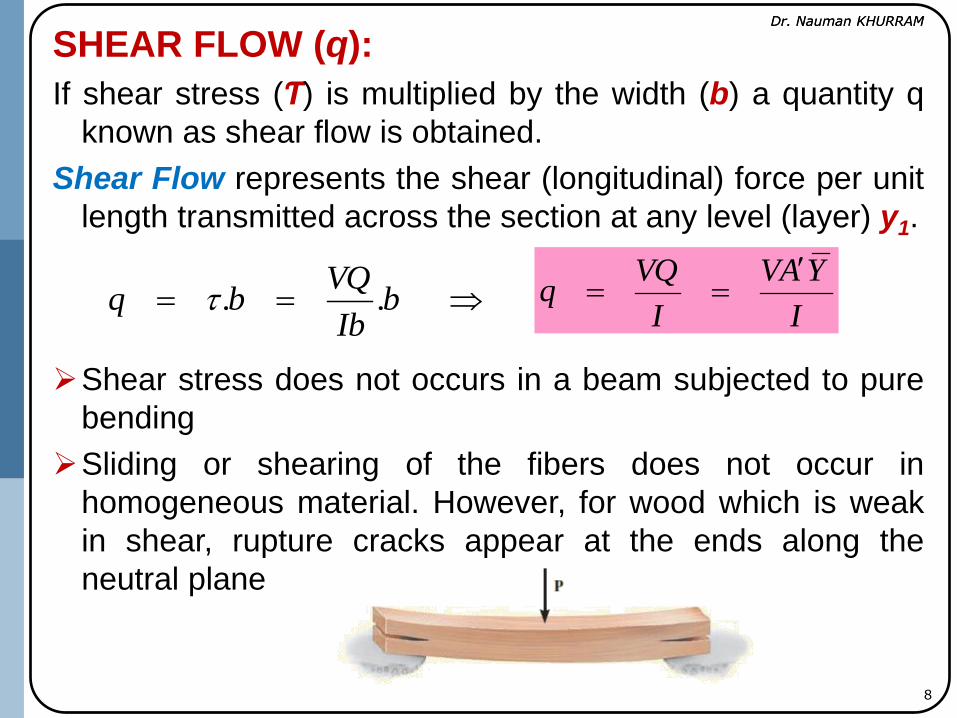
SHEAR FLOW (q):
If shear stress (Ƭ) is multiplied by the width (b) a quantity q
known as shear flow is obtained.
Shear Flow represents the shear (longitudinal) force per unit
length transmitted across the section at any level (layer) y1.
Shear stress does not occurs in a beam subjected to pure
bending
Sliding or shearing of the fibers does not occur in
homogeneous material. However, for wood which is weak
in shear, rupture cracks appear at the ends along the
neutral plane
bIb
VQbq ..
I
YAV
I
VQq

Dr. Nauman KHURRAM Dr. Nauman KHURRAM
9
Relationship Between Horizontal and Vertical
shear Stresses
The horizontal shear stress at any point is always
accompanied by an equal vertical shear stress and are
termed as Complementary Stress.

Dr. Nauman KHURRAM Dr. Nauman KHURRAM
10
Applying (ΣM)c = 0 :
yx
yx dxdzdydydzdx
)..()..(
The vertical shearing stresses are of such magnitude that
their resultant at any cross-section is exactly equal to the
shearing force V at that same section
It is concluded that when a beam
is subjected to transversal loading,
both horizontal and vertical
shearing stresses, numerically
equal in magnitude arise in the
beam

Dr. Nauman KHURRAM Dr. Nauman KHURRAM
11
Horizontal Shear Stresses Distribution
over Cross-Section:
Let assume a beam of rectangular
section bxh, the shear stress at a
layer of distance y from the N.A.
due to shear force ,V at that section
is given as following
2
2
4222
1
2y
h
I
Vy
hyy
hb
Ib
VYA
Ib
V
The equation shows that shear stress is parabolically
distributed across the depth of the section.
The shear stress are maximum at N.A, where y is equal to
zero.
A
V
bh
Vhh
I
V
2
3
)12/(20
42 3
22

Dr. Nauman KHURRAM Dr. Nauman KHURRAM
12
Typical Parabolic Horizontal Distribution Profile
Failure at Neutral Surface due to Maximum Horizontal Stress

Dr. Nauman KHURRAM Dr. Nauman KHURRAM
13
LIMITATION OF SHEAR FORMULA
The shear formula does not give accurate results when
applied to members having cross sections that are short or
flat, or at points where the cross section suddenly changes.
This difference of the stress value is negligible (i.e., 0.8%)
if b < h/4. For the flatter section this difference is even very
large at the end.
Shear formula also should not be applied across a section
that intersects the boundary of the member at an angle
other than 90°.
The shear equation shows that
(Ƭmax) Maximum Shear Stress
are 50% more than the applied
shear (V/A), which is due to the
wrongly assuming the uniform
stress distribution along the
width of section.
Dr. Nauman KHURRAM Dr. Nauman KHURRAM
14
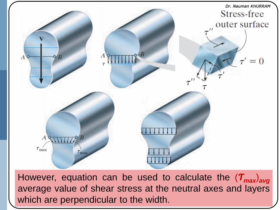
However, equation can be used to calculate the (Ƭmax)avg
average value of shear stress at the neutral axes and layers
which are perpendicular to the width.

Dr. Nauman KHURRAM Dr. Nauman KHURRAM
15
Important points
Shear forces in beams cause nonlinear shear-strain
distributions over the cross section, causing it to warp.
Due to the complementary property of shear stress, the
shear stress developed in a beam acts over the cross
section of the beam and along its longitudinal planes.
Static moment of Inertia (Q) is
maximum at N.A (yi = 0) but Ƭavg may
not maximum as it also depend on
the thickness

Dr. Nauman KHURRAM Dr. Nauman KHURRAM
Shear Stresses in I-section Beam
16
Let consider a differential segment (dx) of cross-section has
two axis of symmetry. Flanges and web are assumed of
uniform thickness. A force dF must act on the longitudinal
section in order to balance the normal forces F1 = F and F2 =
F + dF created by the moments M1 = M and M2 = M + dM
respectively.
If corner elements B and
C of each segment are
removed the Transversal
components of stress , Ƭ
(or Shear Flow, q) act on
the cross section at
cutting plane.

Dr. Nauman KHURRAM Dr. Nauman KHURRAM
17
Considering a small portion of
flange of width dz the magnitude
of longitudinal shear in flange may
be computed by shear formula

Dr. Nauman KHURRAM Dr. Nauman KHURRAM
18
0
2/
2
2)(
2
2/
0
2/
0
bZ
I
Vh
dzI
Vhtdz
h
It
V
ydAIb
VyA
Ib
V
bb
Eqn. shows that shear stress varies linearly from the free end
At z = 0, Ƭ = 0
At z = b/2,
I
Vbhttq
I
Vbhb
I
Vh
4
422
Since cross section is symmetrical
about the y-axis the shear stress in
adjacent flange also increase
linearly from zero at free end edge.

Dr. Nauman KHURRAM Dr. Nauman KHURRAM
19
Considering an small portion of width dy through the web
at a distance y from the junction of flanges and web. In the
evaluation of Q (static moment of area) total area must be
considered above the cut off point.
)(2
)(2
22)(
2)(
yhybhI
VyA
It
V
yhybht
yA
yhty
hbtyA

Dr. Nauman KHURRAM Dr. Nauman KHURRAM
20
At y = b/2,
b
h
I
Vbhttq
b
h
I
Vbh
hbh
I
Vhh
hbh
I
V
41
2
41
2
42)
2(
22
Note that shear stress, Ƭ (or shear flow q) varies
parabolically throughout the depth of the web, attaining the
maximum value at the neutral axes.
In the flanges shear stress is parallel to z-axis and
contribute nothing (negligibly) to the total force on the
section parallel to y-axes.
At the junction of the web and flanges, shear stress in the
web is twice the shear stress in the flanges.
At y = 0,
I
Vbhbh
I
V
20
2
I
Vbhttq
2

Dr. Nauman KHURRAM Dr. Nauman KHURRAM
21
Shear stress in flanges
Shear stress in web
I
Vbhf
2
I
Vbhw
4
Consider a unit length of beam along the line of junction.
For longitudinal equilibrium
fwwf tt 2)1()1(2
If flanges and web are of different thicknesses tf and tw,
respectively then equilibrium condition at junction will be
f
w
f
w
wwff
t
t
tt
2
)1()1(2
Dr. Nauman KHURRAM Dr. Nauman KHURRAM
22
It means, for the flanges and web of an I-section the sum of
shearing force per unit length for the components meeting at
the junction is zero.
ΣƬt = 0
Where, Ƭ is the shear stress in any junction and t is the
thickness of the element.

Dr. Nauman KHURRAM Dr. Nauman KHURRAM
23
Prob 5.62 (Mech. of Material by Andrew Pytel)
The vertical shear force acting on the I-section
shown is 100 kN. Compute
(a) the maximum shear stress acting on the section;
(b) the percentage of the shear force carried by the
web.

Dr. Nauman KHURRAM Dr. Nauman KHURRAM
24
CHARACTERIOSTICS OF SHEAR FLOW
1. Shear flow in the part of the element parallel to the
resisting shear (V) is always in the direction to the
resisting shear force (V) at any section (or opposite to the
applied shear, P).
2. Shear flow occurs in one direction through the thin wall of
the open section
3. At the junction of elements, incoming flow is equal to the
outgoing flow.
4. The value of shear flow is zero at the free tips of the
element and more shear flow is generated as more area
added moving towards the Neutral Axes
5. Shear flow is assumed to be generated from the one side
of N.A and I assumed to be absorbed at other end.
6. The amount of shear flow (q) is proportional to the “First
Moment (Q =Ay) of all the areas added up to the point
under consideration.
Dr. Nauman KHURRAM Dr. Nauman KHURRAM
25
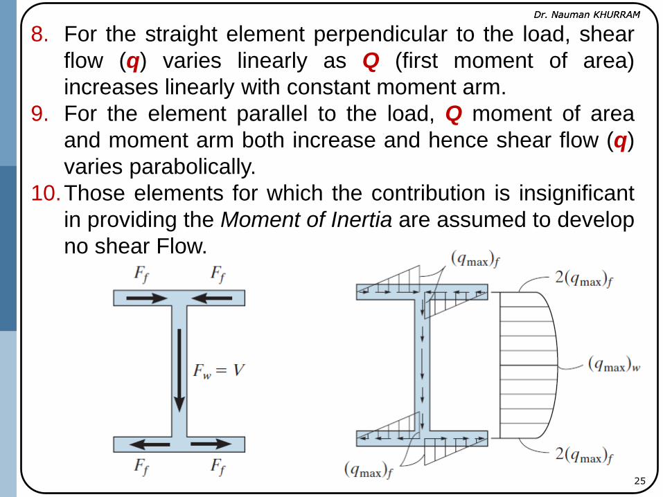
8. For the straight element perpendicular to the load, shear
flow (q) varies linearly as Q (first moment of area)
increases linearly with constant moment arm.
9. For the element parallel to the load, Q moment of area
and moment arm both increase and hence shear flow (q)
varies parabolically.
10.Those elements for which the contribution is insignificant
in providing the Moment of Inertia are assumed to develop
no shear Flow.

Dr. Nauman KHURRAM Dr. Nauman KHURRAM
26