2-Wire Coriolis Flow and Density Meter with MVD · PDF file4 Micro Motion® 2-Wire Coriolis...
32
The Micro Motion ® Model 2200S 2-wire transmitter enables the use of reliable and accurate ELITE ® Coriolis meters virtually anywhere in your plant. The 2-wire Coriolis meter delivers measurement accuracy, repeatability, and operational savings on a level not previously possible in loop-powered applications. Reduce installation costs and increase measurement reliability • Replace existing 2-wire flow devices with minimal effort and without incurring additional power or cabling costs • Low energy, loop-powered design enables easy integration of Coriolis into existing processes for improved measurement and reduced maintenance for an even greater number of flow points • Simplify the complexity and improve the performance of new process plants with loop-powered mA output and HART protocol 2-wire Coriolis • Compact, integral 2-wire transmitter design saves electrical cost and space for use on integrated systems and skids • Direct mass measurement improves process control while reducing number of measurement devices required • Accurate, repeatable measurement ensures higher quality production and overall improved process profitability Product Data Sheet PS-001094, Rev. B March 2009 Micro Motion ® 2-Wire Coriolis Flow and Density Meter with MVD ™ Technology
Transcript of 2-Wire Coriolis Flow and Density Meter with MVD · PDF file4 Micro Motion® 2-Wire Coriolis...

The Micro Motion® Model 2200S 2-wire transmitter enables the use of reliable and accurate ELITE® Coriolis meters virtually anywhere in your plant. The 2-wire Coriolis meter delivers measurement accuracy, repeatability, and operational savings on a level not previously possible in loop-powered applications.
Reduce installation costs and increase measurement reliability
• Replace existing 2-wire flow devices with minimal effort and without incurring additional power or cabling costs
• Low energy, loop-powered design enables easy integration of Coriolis into existing processes for improved measurement and reduced maintenance for an even greater number of flow points
• Simplify the complexity and improve the performance of new process plants with loop-powered mA output and HART protocol 2-wire Coriolis
• Compact, integral 2-wire transmitter design saves electrical cost and space for use on integrated systems and skids
• Direct mass measurement improves process control while reducing number of measurement devices required
• Accurate, repeatable measurement ensures higher quality production and overall improved process profitability
Product Data SheetPS-001094, Rev. BMarch 2009
Micro Motion® 2-Wire Coriolis Flow and Density Meter with MVD™ Technology
2 Micro Motion® 2-Wire Coriolis Flow and Density Meters
Micro Motion 2-wire Coriolis flow and density meter Utilizing Micro Motion MVD technology, the Micro Motion 2-wire Coriolis meter delivers multivariable and diagnostic information via HART® communications. Comprised of a cutting-edge Model 2200S transmitter and the proven best-in-class performance of an ELITE® Coriolis meter, the Micro Motion 2-wire meter brings reduced costs through improved process consistency and maximized uptime. Micro Motion 2-wire Coriolis is ideally suited for use in the chemical, petrochemical and refining industries, and for continuous process and mass balance applications.
MVD technology. MVD technology makes your Micro Motion flowmeter work smarter. Front-end digital processing dramatically reduces signal noise and gives you faster response time compared to analog devices.
Only MVD technology allows you to:
• Measure multiple variables for accurate process control
• Identify and resolve problems easily with built-in smart diagnostics
• Flexible architecture enables tuning for your application needs
• Upgrade transmitter functionality as needed, without impacting availability
Model 2200S transmitters. The Model 2200S transmitter is suitable for a range of process conditions, including CSA Class I Div. 1 and ATEX Zone 1 approvals. To facilitate installation in hazardous areas, Micro Motion offers an adapter-barrier. Finally, the Micro Motion Model 2200S is also available with a 316L stainless steel enclosure suited for harsh environments, such as applications in the offshore and marine industries.
ELITE Coriolis meter. Micro Motion ELITE meters offer accurate measurement for virtually any process fluid, while exhibiting exceptionally low pressure drop. Every ELITE meter features standard secondary containment, and is available with stainless steel or nickel-alloy wetted parts and a wide variety of process connections to meet your every need.
Contents
Liquid flow performance . . . . . . . . . . . . . . . . . . . . 3
Gas flow performance . . . . . . . . . . . . . . . . . . . . . . 4
Density performance (liquid only) . . . . . . . . . . . . . 6
Pressure ratings . . . . . . . . . . . . . . . . . . . . . . . . . . 6
Temperature and humidity specifications . . . . . . . 7
Environmental effects . . . . . . . . . . . . . . . . . . . . . . 8
Hazardous area classifications . . . . . . . . . . . . . . . 9
Physical specifications. . . . . . . . . . . . . . . . . . . . . 11
Weight . . . . . . . . . . . . . . . . . . . . . . . . . . . . . . . . . .11
Micro Motion adapter-barrier. . . . . . . . . . . . . . . . .12
Input/output signals and power supply . . . . . . . . .13
User interface . . . . . . . . . . . . . . . . . . . . . . . . . . . .13
Dimensions . . . . . . . . . . . . . . . . . . . . . . . . . . . . . .14
Fitting options . . . . . . . . . . . . . . . . . . . . . . . . . . . .19
Ordering information . . . . . . . . . . . . . . . . . . . . . . .28

Micro Motion® 2-Wire Coriolis Flow and Density Meters 3
Liquid flow performance
Mass Volume(1)
(1) Specifications for volumetric flow rate are based on a process-fluid density of 1 g/cm3 (1000 kg/m3). For fluids with density other than 1 g/cm3 (1000 kg/m3), the volumetric flow rate equals the mass flow rate divided by the fluid’s density.
lb/min kg/h gal/min l/h
Maximum flow rate CMF010 4 108 0.4 108CMF025 80 2180 10 2180CMF050 250 6800 30 6800CMF100 1000 27,200 120 27,200CMF200 3200 87,100 385 87,100CMF300 10,000 272,000 1200 272,000CMF400 20,000 545,000 2400 545,000
Mass and volume flow accuracy(2)
(2) Stated flow accuracy includes the combined effects of repeatability, linearity, and hysteresis. All specifications for liquids are based on reference conditions of water at 68 to 77 °F (20 to 25 °C) and 15 to 30 psig (1 to 2 bar), unless otherwise noted.
±0.10% of rate(3)
(3) When flow rate is less than zero stability / 0.001, accuracy = ±[(zero stability / flow rate) × 100]% of rate andrepeatability = ±[½(zero stability / flow rate) × 100]% of rate.
Mass and volume flow repeatability ±0.05% of rate(3)
lb/min kg/h
Zero stability CMF010 0.000075 0.002CMF010P 0.00015 0.004CMF025 0.001 0.027CMF050 0.006 0.163CMF100 0.025 0.680CMF200 0.08 2.18CMF300 0.25 6.80CMF400 1.50 40.91
Typical accuracy and turndownThe graph below is an example of the relationship between accuracy and turndown on water. To determine actual accuracy and turndown with your process variables, use the Micro Motion product selector, available at www.micromotion.com.
–2.5
–2.0
–1.5
–1.0
–0.5
0
0.5
1.0
1.5
2.0
2.5
1009080706050403020100
100:1
20:1
10:1
1:1
Flow rate, % of maximum
Acc
ura
cy, %
Turndown 500:1 100:1 20:1 10:1 1:1Accuracy (±%) 2.40 0.50 0.10 0.10 0.10
4 Micro Motion® 2-Wire Coriolis Flow and Density Meters
Gas flow performance
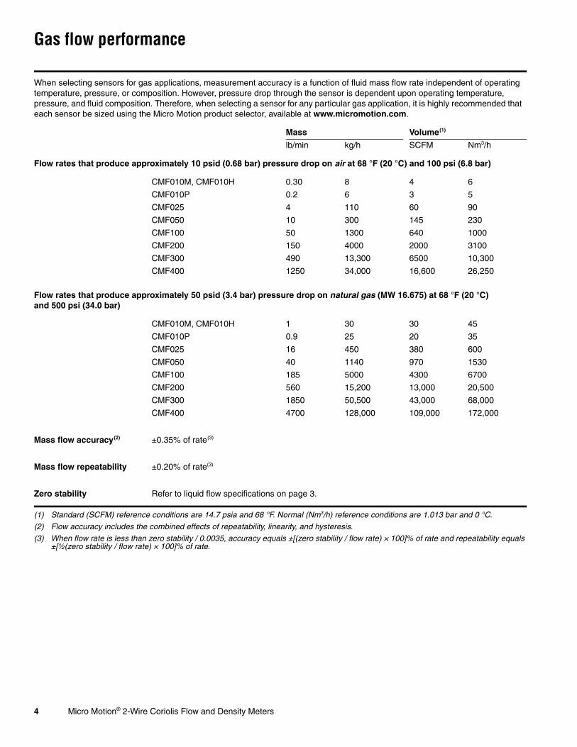
When selecting sensors for gas applications, measurement accuracy is a function of fluid mass flow rate independent of operating temperature, pressure, or composition. However, pressure drop through the sensor is dependent upon operating temperature, pressure, and fluid composition. Therefore, when selecting a sensor for any particular gas application, it is highly recommended that each sensor be sized using the Micro Motion product selector, available at www.micromotion.com.
Mass Volume(1)
(1) Standard (SCFM) reference conditions are 14.7 psia and 68 °F. Normal (Nm3/h) reference conditions are 1.013 bar and 0 °C.
lb/min kg/h SCFM Nm3/h
Flow rates that produce approximately 10 psid (0.68 bar) pressure drop on air at 68 °F (20 °C) and 100 psi (6.8 bar)
CMF010M, CMF010H 0.30 8 4 6
CMF010P 0.2 6 3 5
CMF025 4 110 60 90
CMF050 10 300 145 230
CMF100 50 1300 640 1000
CMF200 150 4000 2000 3100
CMF300 490 13,300 6500 10,300
CMF400 1250 34,000 16,600 26,250
Flow rates that produce approximately 50 psid (3.4 bar) pressure drop on natural gas (MW 16.675) at 68 °F (20 °C) and 500 psi (34.0 bar)
CMF010M, CMF010H 1 30 30 45
CMF010P 0.9 25 20 35
CMF025 16 450 380 600
CMF050 40 1140 970 1530
CMF100 185 5000 4300 6700
CMF200 560 15,200 13,000 20,500
CMF300 1850 50,500 43,000 68,000
CMF400 4700 128,000 109,000 172,000
Mass flow accuracy(2)
(2) Flow accuracy includes the combined effects of repeatability, linearity, and hysteresis.
±0.35% of rate(3)
(3) When flow rate is less than zero stability / 0.0035, accuracy equals ±[(zero stability / flow rate) × 100]% of rate and repeatability equals ±[½(zero stability / flow rate) × 100]% of rate.
Mass flow repeatability ±0.20% of rate(3)
Zero stability Refer to liquid flow specifications on page 3.
Micro Motion® 2-Wire Coriolis Flow and Density Meters 5
Gas flow performance continued
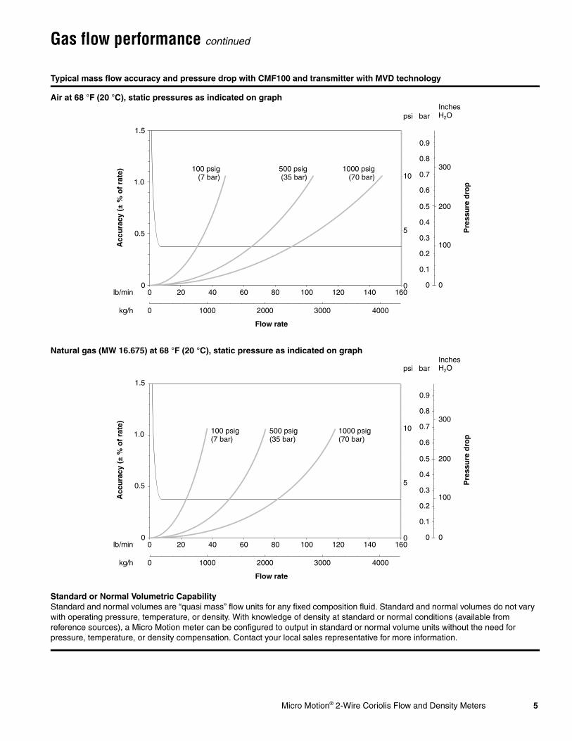
Typical mass flow accuracy and pressure drop with CMF100 and transmitter with MVD technology
Air at 68 °F (20 °C), static pressures as indicated on graph
Natural gas (MW 16.675) at 68 °F (20 °C), static pressure as indicated on graph
Standard or Normal Volumetric CapabilityStandard and normal volumes are “quasi mass” flow units for any fixed composition fluid. Standard and normal volumes do not vary with operating pressure, temperature, or density. With knowledge of density at standard or normal conditions (available from reference sources), a Micro Motion meter can be configured to output in standard or normal volume units without the need for pressure, temperature, or density compensation. Contact your local sales representative for more information.
1.5
1.0
0.5
0
5
10
Flow rate
Pre
ssu
re d
rop
Acc
ura
cy (
± %
of
rate
)
0 20 40 60 80 100 120 140 1600
0 1000 2000 3000 4000
lb/min
kg/h
300
200
100
0
0.5
0.4
0.3
0.2
0.1
0
0.9
0.8
0.7
0.6
barInchesH2Opsi
100 psig(7 bar)
500 psig(35 bar)
1000 psig(70 bar)
1.5
1.0
0.5
0
5
10
Flow rate
Pre
ssu
re d
rop
Acc
ura
cy (
± %
of
rate
)
0 20 40 60 80 100 120 140 1600
0 1000 2000 3000 4000
lb/min
kg/h
300
200
100
0
0.5
0.4
0.3
0.2
0.1
0
0.9
0.8
0.7
0.6
barInchesH2Opsi
100 psig(7 bar)
500 psig(35 bar)
1000 psig(70 bar)
6 Micro Motion® 2-Wire Coriolis Flow and Density Meters
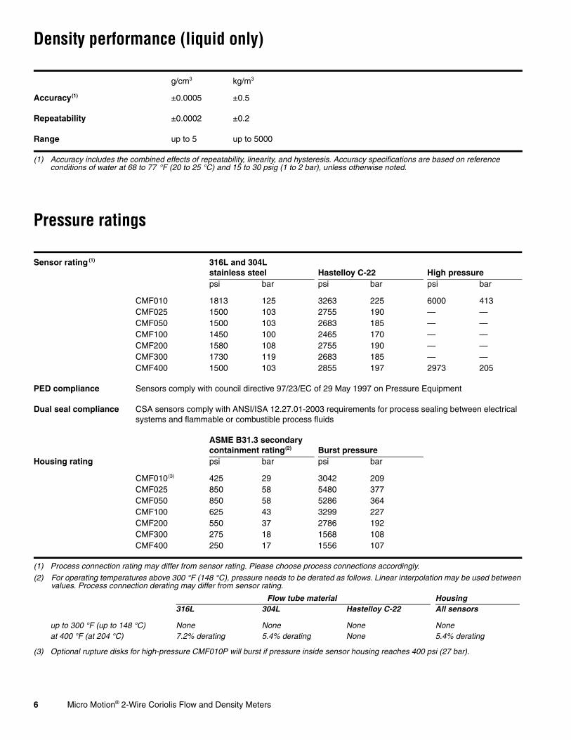
Density performance (liquid only)
Pressure ratings
g/cm3 kg/m3
Accuracy(1)
(1) Accuracy includes the combined effects of repeatability, linearity, and hysteresis. Accuracy specifications are based on reference conditions of water at 68 to 77 °F (20 to 25 °C) and 15 to 30 psig (1 to 2 bar), unless otherwise noted.
±0.0005 ±0.5
Repeatability ±0.0002 ±0.2
Range up to 5 up to 5000
Sensor rating (1)
(1) Process connection rating may differ from sensor rating. Please choose process connections accordingly.
316L and 304L stainless steel Hastelloy C-22 High pressurepsi bar psi bar psi bar
CMF010 1813 125 3263 225 6000 413CMF025 1500 103 2755 190 — —CMF050 1500 103 2683 185 — —CMF100 1450 100 2465 170 — —CMF200 1580 108 2755 190 — —CMF300 1730 119 2683 185 — —CMF400 1500 103 2855 197 2973 205
PED compliance Sensors comply with council directive 97/23/EC of 29 May 1997 on Pressure Equipment
Dual seal compliance CSA sensors comply with ANSI/ISA 12.27.01-2003 requirements for process sealing between electrical systems and flammable or combustible process fluids
ASME B31.3 secondarycontainment rating(2)
(2) For operating temperatures above 300 °F (148 °C), pressure needs to be derated as follows. Linear interpolation may be used between values. Process connection derating may differ from sensor rating.
Burst pressureHousing rating psi bar psi bar
CMF010(3)
(3) Optional rupture disks for high-pressure CMF010P will burst if pressure inside sensor housing reaches 400 psi (27 bar).
425 29 3042 209CMF025 850 58 5480 377CMF050 850 58 5286 364CMF100 625 43 3299 227CMF200 550 37 2786 192CMF300 275 18 1568 108CMF400 250 17 1556 107
Flow tube material Housing316L 304L Hastelloy C-22 All sensors
up to 300 °F (up to 148 °C) None None None Noneat 400 °F (at 204 °C) 7.2% derating 5.4% derating None 5.4% derating
Micro Motion® 2-Wire Coriolis Flow and Density Meters 7
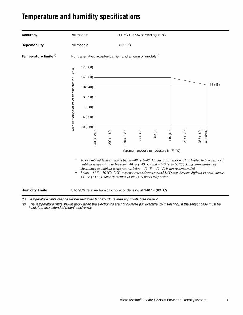
Temperature and humidity specifications
Accuracy All models ±1 °C ± 0.5% of reading in °C
Repeatability All models ±0.2 °C
Temperature limits(1)
(1) Temperature limits may be further restricted by hazardous area approvals. See page 9.
For transmitter, adapter-barrier, and all sensor models(2)
(2) The temperature limits shown apply when the electronics are not covered (for example, by insulation). If the sensor case must be insulated, use extended mount electronics.
Humidity limits 5 to 95% relative humidity, non-condensing at 140 °F (60 °C)
Am
bien
t tem
pera
ture
of t
rans
mitt
er in
°F
(°C
)
Maximum process temperature in °F (°C)
–40 (–40)
–4 (–20)
32 (0)
68 (20)
104 (40)
140 (60)
176 (80)
–400
(–2
40)
–292
(–1
80)
–184
(–1
20)
–76
(–60
)
32 (
0)
140
(60)
356
(180
)
248
(120
)
113 (45)
400
(204
)
* When ambient temperature is below –40 °F (–40 °C), the transmitter must be heated to bring its local ambient temperature to between –40 °F (–40 °C) and +140 °F (+60 °C). Long-term storage of electronics at ambient temperatures below –40 °F (–40 °C) is not recommended.
* Below –4 °F (–20 °C), LCD responsiveness decreases and LCD may become difficult to read. Above 131 °F (55 °C), some darkening of the LCD panel may occur.
8 Micro Motion® 2-Wire Coriolis Flow and Density Meters
Environmental effects
Process temperature effect Process temperature effect is defined as:• For mass flow measurement, the worst-case zero offset due to process fluid temperature
change away from the zeroing temperature.• For density measurement, the maximum measurement offset due to process fluid
temperature change away from the density calibration temperature.
Process temperature effect% of maximum flow rate per °C density accuracy per °C(1)
(1) For –100 °C and above.
g/cm3 kg/m3
CMF010 ±0.0001875 ±0.000015 ±0.015CMF025 ±0.0001250 ±0.000015 ±0.015CMF050 ±0.0001250 ±0.000015 ±0.015CMF100 ±0.0001250 ±0.000015 ±0.015CMF200 ±0.0005000 ±0.000015 ±0.015CMF300 ±0.0005000 ±0.000015 ±0.015CMF400 ±0.0007500 ±0.000015 ±0.015
Ambient temperature effect On mA output: ±0.005% of span per °C
Pressure effect Pressure effect is defined as the change in sensor flow and density sensitivity due to process pressure change away from the calibration pressure. Pressure effect can be corrected.
Pressure effect on flow accuracy% of rate per psi % of rate per barliquid gas liquid gas
CMF010 None None None NoneCMF025 None None None NoneCMF050 None None None NoneCMF100 –0.0002 None –0.003 NoneCMF200 –0.0008 –0.0004 –0.012 –0.006CMF300 –0.0006 –0.0003 –0.009 –0.0045CMF400 –0.001 –0.0005 –0.015 –0.0075
Pressure effect on density accuracyg/cm3 per psi kg/m3 per bar
CMF010 None NoneCMF025 0.000004 0.058CMF050 –0.000002 –0.029CMF100 –0.000006 –0.087CMF200 0.000001 0.0145CMF300 0.0000002 0.0029CMF400 –0.00001 –0.145
EMI effects Complies with EMC directive 2004/108/EC per EN 61326 IndustrialConforms to NAMUR NE21 Version: 08.22.2007
Vibration limits Meets IEC 68.2.6, endurance sweep, 5 to 2000 Hz, 50 sweep cycles at 1.0 g
Micro Motion® 2-Wire Coriolis Flow and Density Meters 9
Hazardous area classifications
ELITE sensor with Model 2200S transmitter
CSA C-US
All models Ambient temperature –40 to +140 °F (–40 to +60 °C)
Class I, Div. 1, Groups C and D
Class I, Div. 2, Groups A, B, C, and D
Class II, Div. 1, Groups E, F, and G
IECEx
Models CMF010, CMF025, CMF050, and CMF100
Ex ib IIC T1–T4
Ex nA II T1–T4
Model CMF200, CMF300, and CMF400 Ex ib IIB T1–T4
Ex nA II T1–T4
ATEX
Models CMF010, CMF025, CMF050, and CMF100
0575 II 2G Ex ib IIC T1–T4
II 2D Ex ibD 21 T70 °C
II 3G Ex nA II T1–T4
II 3D Ex tD A22 IP65 T70 °C
Model CMF200 and CMF300 0575 II 2G Ex ib IIB T1–T4
II 2D Ex ibD 21 T70 °C
II 3G Ex nA II T1–T4
II 3D Ex tD A22 IP65 T70 °C
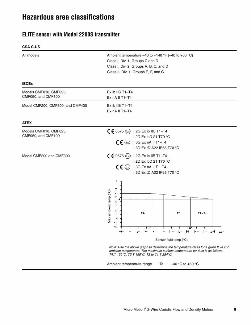
Ambient temperature range Ta –40 °C to +60 °C
Sensor fluid temp (°C)
Max
am
bien
t tem
p (°
C)
Note: Use the above graph to determine the temperature class for a given fluid and ambient temperature. The maximum surface temperature for dust is as follows: T4:T 130°C, T3:T 195°C, T2 to T1:T 254°C.

10 Micro Motion® 2-Wire Coriolis Flow and Density Meters
Hazardous area classifications continued
Adapter-barrier
ATEX
Model CMF400 0575 II 2G Ex ib IIB T1–T4
II 2D Ex ibD 21 T70 °C
II 3G Ex nA II T1–T4
II 3D Ex tD A22 IP65 T70 °C
Ambient temperature range Ta –40 to +60 °C
CSA C-US
Class I, Div. 1, Groups C and D(1)
(1) When installed in a suitable enclosure.
Class I, Div. 2, Groups A, B, C, and D
Class II, Div. 2, Groups F and G
IECEx
[Ex ib] IIB/IIC
ATEX
0575 II (2) G [Ex ib] IIB/IIC
II (2) D [Ex ibD]
Sensor fluid temp (°C)
Max
am
bien
t tem
p (°
C)
Note: Use the above graph to determine the temperature class for a given fluid and ambient temperature. The maximum surface temperature for dust is as follows: T4:T 130°C, T3:T 195°C, T2 to T1:T 234°C
Micro Motion® 2-Wire Coriolis Flow and Density Meters 11
Physical specifications
Weight
Wetted parts(1)
(1) General corrosion guides do not account for cyclical stress, and therefore should not be relied upon when choosing a wetted material for your Micro Motion sensor. Please refer to the Micro Motion corrosion guide for proper material compatibility information.
316L or 304L stainless steel, or Hastelloy C-22
Sensor housing 304L stainless steel(2)
(2) 316L stainless steel is available.
Transmitter housing Integral mount or extended mount
NEMA 4X (IP66/67) polyurethane-painted cast aluminum or 316L stainless steel Available with 1/2”–NPT or M20 × 1.5 conduit connections
The transmitter can be rotated on the mounting in 45° increments, for eight different orientations.
Adapter-barrier IP20 housingDIN rail mounting type: DIN 46277Can be stacked side-to-side
lb kg
Sensor and transmitter(1)
(1) Weight of sensor and polyurethane-painted aluminum transmitter with ANSI CL150 welded flanges. For stainless steel transmitter, add 4 lb (2 kg).
CMF010 19 9
CMF025 13 6
CMF050 17 8
CMF100 34 16
CMF200 68 31
CMF300 170 77
CMF400 446 202
Adapter-barrier 0.33 0.15

12 Micro Motion® 2-Wire Coriolis Flow and Density Meters
Micro Motion adapter-barrier
The Micro Motion adapter-barrier provides Class I, Div. 1 and Zone 1 intrinsic safety protection, and re-spans the I/O signalfrom 12–20 mA to 4–20 mA.
Transmitter to host with no barrier
Transmitter to host with third-party barrier
Transmitter to host with Micro Motion adapter-barrier
mA receiving device
DCS
12–20 mA HART 2-wire connection
Model 2200S
mA receiving device
DCS
12–20 mA HART
Safe area Hazardous area
3rd-party barrier
2-wire connection
Model 2200S
mA receiving device
DCS
4–20 mA HART
Safe area Hazardous area
Adapter-barrier
2-wire connection
Model 2200S

Micro Motion® 2-Wire Coriolis Flow and Density Meters 13
Input/output signals and power supply
User interface
Transmitter One passive 12–20 mA output• Isolated to ±50 VDC from earth ground• Maximum load limit: 600 Ω• External power: 17–36 VDC• 0.8 W maximum• Can report mass flow, liquid volume flow, gas standard volume flow, density,
temperature, or drive gain• Output is linear with process from 11.9 to 20.25 mA
Adapter-barrier Isolation voltage• Power to field side: > 1500 VAC• Power to host side: > 500 VAC• Field to host side: > 1500 VAC
Power supply• 18–42 VDC• Maximum supply current: 170 mA• Maximum power: 3 W
Field side• One passive 12–20 mA input• Over/under range: 11–21 mA• HART pass-through• Loop supply: > 25 V• HART-compliant impedance: > 250 Ω • Compliant with ATEX, CSA, and IECEx intrinsic safety requirements
Host side• One active or passive 4–20 mA output• Over/under range: 2–22 mA• Maximum load limit (active output): < 1 kΩ • Maximum loop voltage (passive input): < 36 V• Linearity: < 0.05% span• Conforms to NAMUR NE43 (February 2003) (depending on transmitter configuration)
EMI effects:Conforms to NAMUR NE21 Version 08.22.2007
Standard user interface with LCD panel• Suitable for hazardous area installation.• User interface module can rotate 360° on the transmitter in 90° increments.• Two clips for HART/Bell 202 connections (requires removing transmitter housing cover).• Two membrane pushbuttons for local operation (requires removing transmitter
housing cover).• Depending on purchase option, transmitter housing cover has glass or plastic lens.• User interface module includes LCD panel. LCD line 1 displays process variable; line 2
displays engineering unit of measure, with optional alarm indication.• LCD panel can be configured to scroll through display list at user-specified scroll rate.
Display list includes user-selected process variables and, optionally, all active alarms.• Display update rate is user-configurable: 100 to 10,000 milliseconds.
14 Micro Motion® 2-Wire Coriolis Flow and Density Meters
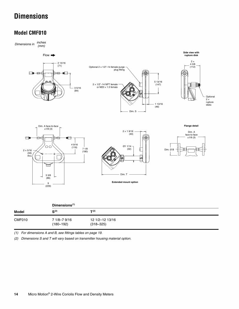
Dimensions
Model CMF010
Dimensions(1)
(1) For dimensions A and B, see fittings tables on page 19.
Model S(2)
(2) Dimensions S and T will vary based on transmitter housing material option.
T(2)
CMF010 7 1/8–7 9/16(180–192)
12 1/2–12 13/16(318–325)
Dimensions in inches(mm)
Flow
2 13/16(71)
3 5/16(84)
Optional 2 × 1/2”–14 female purgeplug fitting
Dim. S
1 13/16(46)
5 13/16(147)
Ø1 1/14(32)
Dim. T
Dim. A face-to-face±1/8 (3)
2 × 5/16(59)thru
3 3/8(86)
9(229)
4 9/16(116)
7 1/8(180)
2 ×4 3/8(112)
Optional2 ×rupture disks
Side view with rupture disk
Flange detail
Dim. A face-to-face
±1/8 (3)
Dim. Ø B
2 × 1/2”–14 NPT femaleor M20 × 1.5 female
Extended mount option
2 × 1 9/16(40)
Micro Motion® 2-Wire Coriolis Flow and Density Meters 15
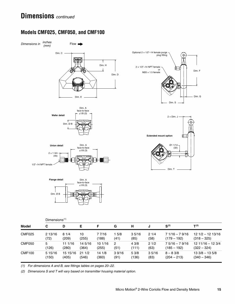
Dimensions continued
Models CMF025, CMF050, and CMF100
Dimensions(1)
(1) For dimensions A and B, see fittings tables on pages 20–22.
Model C D E F G H J S(2)
(2) Dimensions S and T will vary based on transmitter housing material option.
T(2)
CMF025 2 13/16(72)
8 1/4(209)
10(255)
7 7/16(188)
1 5/8(41)
3 5/16(85)
2 1/4(58)
7 1/16 – 7 9/16(179 – 192)
12 1/2 – 12 13/16(318 – 325)
CMF050 5(126)
11 1/16(280)
14 5/16(364)
10 1/16(255)
2(51)
4 3/8(111)
2 1/2(63)
7 5/16 – 7 9/16(185 – 192)
12 11/16 – 12 3/4(322 – 324)
CMF100 5 15/16(150)
15 15/16(405)
21 1/2(546)
14 1/8(360)
3 9/16(91)
5 3/8(136)
3 5/16(83)
8 – 8 3/8(204 – 213)
13 3/8 – 13 5/8(340 – 346)
Dimensions in inches(mm)
Dim. S
Ø1 1/14(32)
Dim. T
Flow
Dim. A face-to-face
±1/8 (3)
Dim. Ø B
Dim. A face-to-face
±1/8 (3)
Dim. A face-to-face
±1/8 (3)
Dim. Ø B
Dim. C
Dim. D
Dim. E
Dim. F
2 × 1/2”–14 NPT femaleor
M20 × 1.5 female
Optional 2 × 1/2”–14 female purgeplug fitting
Dim. G
Dim. H
2 × 1 3/4(45)
1/2”–14 NPT female
2 × Dim. J
Extended mount option
Wafer detail
Union detail
Flange detail

16 Micro Motion® 2-Wire Coriolis Flow and Density Meters
Dimensions continued
Models CMF200 and CMF300
Dimensions(1)
(1) For dimensions A and B, see fittings tables on pages 23–25.
Model C D E F G H J S(2)
(2) Dimensions S and T will vary based on transmitter housing material option.
T(2)
CMF200 14(356)
28 5/8(727)
19 9/16(497)
6 7/8(175)
5 9/16(142)
11 7/8(302)
4 5/16(110)
9 1/8 – 9 7/16(232 – 239)
14 1/2 – 14 5/8(368 – 372)
CMF300 22(559)
38 7/16(977)
30 3/16(767)
9 3/8(238)
8 3/16(209)
13 7/8(352)
5 5/8(143)
10 1/2 – 10 3/4(266 – 273)
15 7/8 – 16(403 – 406)
Dimensions in inches(mm)
Dim. Ø B
Dim. A face-to-face
±1/8 (3)
Flow
Dim. D
Dim. H
Dim. E
Dim. C
2 × 1/2”–14 NPT femaleor M20 × 1.5 female
Optional 2 × 1/2”–14 femalepurge plug fitting
2 × Dim. J
Dim. G
Dim. S
Dim. T
Ø1 1/14(32)
Extended mount option
Dim. F
Micro Motion® 2-Wire Coriolis Flow and Density Meters 17
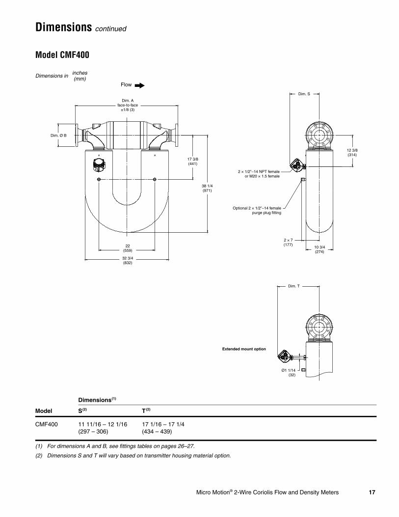
Dimensions continued
Model CMF400
Dimensions(1)
(1) For dimensions A and B, see fittings tables on pages 26–27.
Model S(2)
(2) Dimensions S and T will vary based on transmitter housing material option.
T(2)
CMF400 11 11/16 – 12 1/16(297 – 306)
17 1/16 – 17 1/4(434 – 439)
Dimensions in inches(mm)
Dim. Ø B
Dim. A face-to-face
±1/8 (3)
Flow
2 × 1/2”–14 NPT femaleor M20 × 1.5 female
Optional 2 × 1/2”–14 femalepurge plug fitting
Ø1 1/14(32)
Extended mount option
17 3/8(441)
38 1/4(971)
22(559)
32 3/4(832)
2 × 7(177)
10 3/4(274)
12 3/8(314)
Dim. S
Dim. T
18 Micro Motion® 2-Wire Coriolis Flow and Density Meters
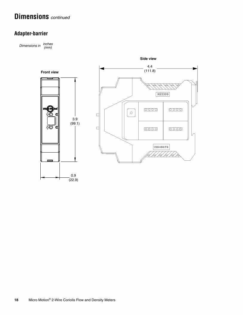
Dimensions continued
Adapter-barrier
4.4(111.8)
0.9(22.9)
3.9(99.1)
Dimensions in inches(mm)
Front view
Side view
Micro Motion® 2-Wire Coriolis Flow and Density Meters 19
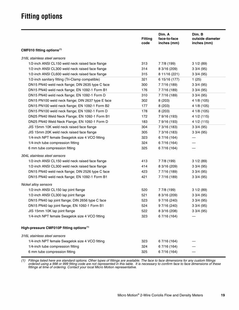
Fitting options
Fitting code
Dim. A face-to-faceinches (mm)
Dim. B outside diameterinches (mm)
CMF010 fitting options(1)
(1) Fittings listed here are standard options. Other types of fittings are available. The face to face dimensions for any custom fittings ordered using a 998 or 999 fitting code are not represented in this table. It is necessary to confirm face to face dimensions of these fittings at time of ordering. Contact your local Micro Motion representative.
316L stainless steel sensors
1/2-inch ANSI CL150 weld neck raised face flange 313 7 7/8 (199) 3 1/2 (89)
1/2-inch ANSI CL300 weld neck raised face flange 314 8 3/16 (209) 3 3/4 (95)
1/2-inch ANSI CL600 weld neck raised face flange 315 8 11/16 (221) 3 3/4 (95)
1/2-inch sanitary fitting (Tri-Clamp compatible) 321 6 15/16 (177) 1 (25)
DN15 PN40 weld neck flange; DIN 2635 type C face 300 7 7/16 (189) 3 3/4 (95)
DN15 PN40 weld neck flange; EN 1092-1 Form B1 176 7 7/16 (189) 3 3/4 (95)
DN15 PN40 weld neck flange; EN 1092-1 Form D 310 7 7/16 (189) 3 3/4 (95)
DN15 PN100 weld neck flange; DIN 2637 type E face 302 8 (203) 4 1/8 (105)
DN15 PN100 weld neck flange; EN 1092-1 Form B2 177 8 (203) 4 1/8 (105)
DN15 PN100 weld neck flange; EN 1092-1 Form D 178 8 (203) 4 1/8 (105)
DN25 PN40 Weld Neck Flange; EN 1092-1 Form B1 172 7 9/16 (193) 4 1/2 (115)
DN25 PN40 Weld Neck Flange; EN 1092-1 Form D 183 7 9/16 (193) 4 1/2 (115)
JIS 15mm 10K weld neck raised face flange 304 7 3/16 (183) 3 3/4 (95)
JIS 15mm 20K weld neck raised face flange 305 7 3/16 (183) 3 3/4 (95)
1/4-inch NPT female Swagelok size 4 VCO fitting 323 6 7/16 (164) —
1/4-inch tube compression fitting 324 6 7/16 (164) —
6 mm tube compression fitting 325 6 7/16 (164) —
304L stainless steel sensors
1/2-inch ANSI CL150 weld neck raised face flange 413 7 7/8 (199) 3 1/2 (89)
1/2-inch ANSI CL300 weld neck raised face flange 414 8 3/16 (209) 3 3/4 (95)
DN15 PN40 weld neck flange; DIN 2526 type C face 423 7 7/16 (189) 3 3/4 (95)
DN15 PN40 weld neck flange; EN 1092-1 Form B1 421 7 7/16 (189) 3 3/4 (95)
Nickel alloy sensors
1/2-inch ANSI CL150 lap joint flange 520 7 7/8 (199) 3 1/2 (89)
1/2-inch ANSI CL300 lap joint flange 521 8 3/16 (209) 3 3/4 (95)
DN15 PN40 lap joint flange; DIN 2656 type C face 523 9 7/16 (240) 3 3/4 (95)
DN15 PN40 lap joint flange; EN 1092-1 Form B1 524 9 7/16 (240) 3 3/4 (95)
JIS 15mm 10K lap joint flange 522 8 3/16 (208) 3 3/4 (95)
1/4-inch NPT female Swagelok size 4 VCO fitting 323 6 7/16 (164) —
High-pressure CMF010P fitting options(1)
316L stainless steel sensors
1/4-inch NPT female Swagelok size 4 VCO fitting 323 6 7/16 (164) —
1/4-inch tube compression fitting 324 6 7/16 (164) —
6 mm tube compression fitting 325 6 7/16 (164) —
20 Micro Motion® 2-Wire Coriolis Flow and Density Meters
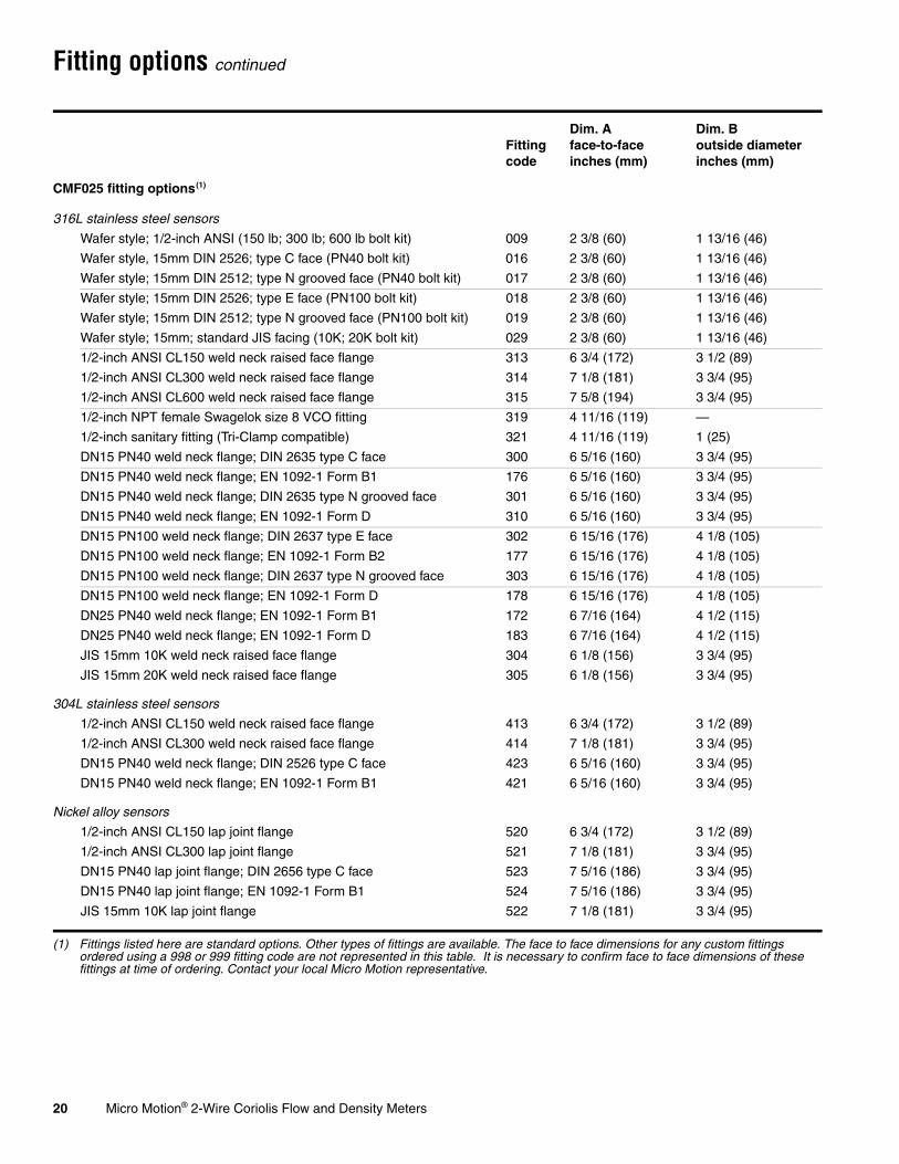
Fitting options continued
Fitting code
Dim. A face-to-faceinches (mm)
Dim. B outside diameterinches (mm)
CMF025 fitting options(1)
(1) Fittings listed here are standard options. Other types of fittings are available. The face to face dimensions for any custom fittings ordered using a 998 or 999 fitting code are not represented in this table. It is necessary to confirm face to face dimensions of these fittings at time of ordering. Contact your local Micro Motion representative.
316L stainless steel sensors
Wafer style; 1/2-inch ANSI (150 lb; 300 lb; 600 lb bolt kit) 009 2 3/8 (60) 1 13/16 (46)
Wafer style, 15mm DIN 2526; type C face (PN40 bolt kit) 016 2 3/8 (60) 1 13/16 (46)
Wafer style; 15mm DIN 2512; type N grooved face (PN40 bolt kit) 017 2 3/8 (60) 1 13/16 (46)
Wafer style; 15mm DIN 2526; type E face (PN100 bolt kit) 018 2 3/8 (60) 1 13/16 (46)
Wafer style; 15mm DIN 2512; type N grooved face (PN100 bolt kit) 019 2 3/8 (60) 1 13/16 (46)
Wafer style; 15mm; standard JIS facing (10K; 20K bolt kit) 029 2 3/8 (60) 1 13/16 (46)
1/2-inch ANSI CL150 weld neck raised face flange 313 6 3/4 (172) 3 1/2 (89)
1/2-inch ANSI CL300 weld neck raised face flange 314 7 1/8 (181) 3 3/4 (95)
1/2-inch ANSI CL600 weld neck raised face flange 315 7 5/8 (194) 3 3/4 (95)
1/2-inch NPT female Swagelok size 8 VCO fitting 319 4 11/16 (119) —
1/2-inch sanitary fitting (Tri-Clamp compatible) 321 4 11/16 (119) 1 (25)
DN15 PN40 weld neck flange; DIN 2635 type C face 300 6 5/16 (160) 3 3/4 (95)
DN15 PN40 weld neck flange; EN 1092-1 Form B1 176 6 5/16 (160) 3 3/4 (95)
DN15 PN40 weld neck flange; DIN 2635 type N grooved face 301 6 5/16 (160) 3 3/4 (95)
DN15 PN40 weld neck flange; EN 1092-1 Form D 310 6 5/16 (160) 3 3/4 (95)
DN15 PN100 weld neck flange; DIN 2637 type E face 302 6 15/16 (176) 4 1/8 (105)
DN15 PN100 weld neck flange; EN 1092-1 Form B2 177 6 15/16 (176) 4 1/8 (105)
DN15 PN100 weld neck flange; DIN 2637 type N grooved face 303 6 15/16 (176) 4 1/8 (105)
DN15 PN100 weld neck flange; EN 1092-1 Form D 178 6 15/16 (176) 4 1/8 (105)
DN25 PN40 weld neck flange; EN 1092-1 Form B1 172 6 7/16 (164) 4 1/2 (115)
DN25 PN40 weld neck flange; EN 1092-1 Form D 183 6 7/16 (164) 4 1/2 (115)
JIS 15mm 10K weld neck raised face flange 304 6 1/8 (156) 3 3/4 (95)
JIS 15mm 20K weld neck raised face flange 305 6 1/8 (156) 3 3/4 (95)
304L stainless steel sensors
1/2-inch ANSI CL150 weld neck raised face flange 413 6 3/4 (172) 3 1/2 (89)
1/2-inch ANSI CL300 weld neck raised face flange 414 7 1/8 (181) 3 3/4 (95)
DN15 PN40 weld neck flange; DIN 2526 type C face 423 6 5/16 (160) 3 3/4 (95)
DN15 PN40 weld neck flange; EN 1092-1 Form B1 421 6 5/16 (160) 3 3/4 (95)
Nickel alloy sensors
1/2-inch ANSI CL150 lap joint flange 520 6 3/4 (172) 3 1/2 (89)
1/2-inch ANSI CL300 lap joint flange 521 7 1/8 (181) 3 3/4 (95)
DN15 PN40 lap joint flange; DIN 2656 type C face 523 7 5/16 (186) 3 3/4 (95)
DN15 PN40 lap joint flange; EN 1092-1 Form B1 524 7 5/16 (186) 3 3/4 (95)
JIS 15mm 10K lap joint flange 522 7 1/8 (181) 3 3/4 (95)
Micro Motion® 2-Wire Coriolis Flow and Density Meters 21
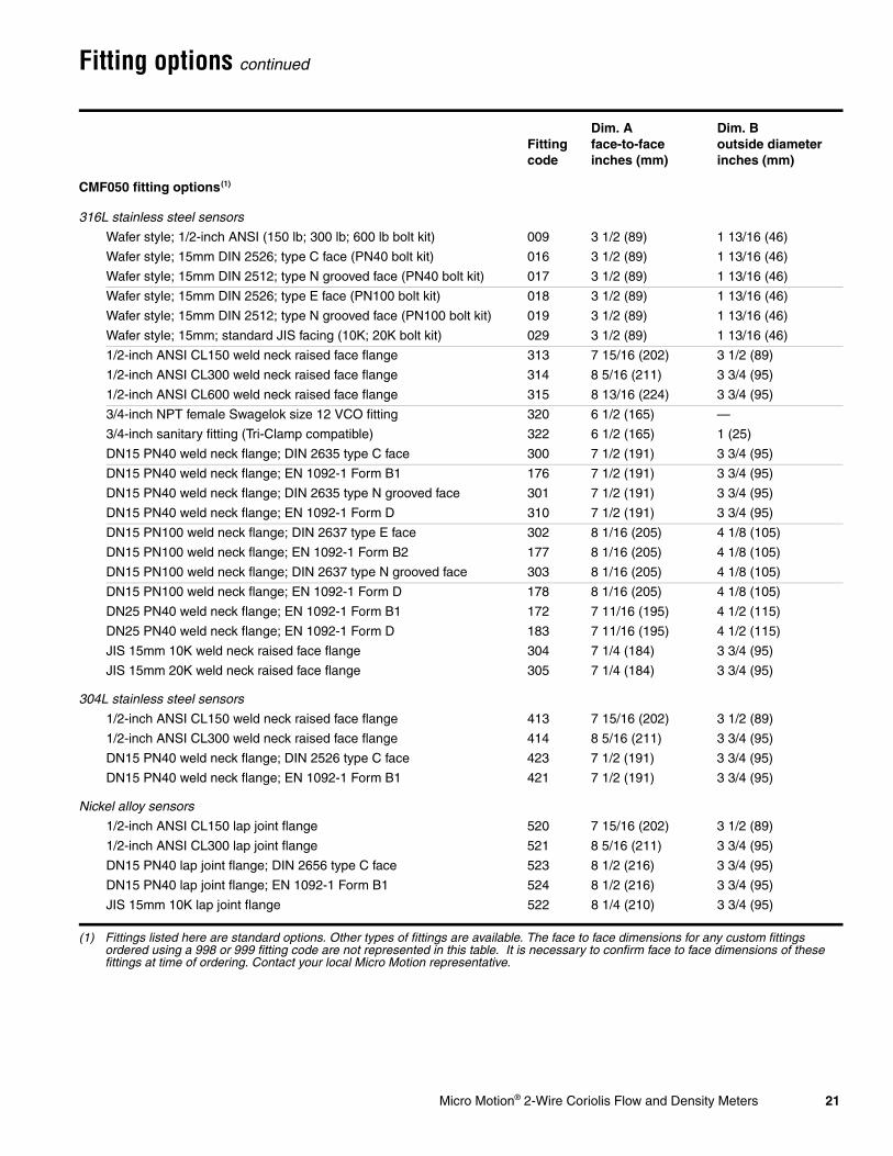
Fitting options continued
Fitting code
Dim. A face-to-faceinches (mm)
Dim. B outside diameterinches (mm)
CMF050 fitting options(1)
(1) Fittings listed here are standard options. Other types of fittings are available. The face to face dimensions for any custom fittings ordered using a 998 or 999 fitting code are not represented in this table. It is necessary to confirm face to face dimensions of these fittings at time of ordering. Contact your local Micro Motion representative.
316L stainless steel sensors
Wafer style; 1/2-inch ANSI (150 lb; 300 lb; 600 lb bolt kit) 009 3 1/2 (89) 1 13/16 (46)
Wafer style; 15mm DIN 2526; type C face (PN40 bolt kit) 016 3 1/2 (89) 1 13/16 (46)
Wafer style; 15mm DIN 2512; type N grooved face (PN40 bolt kit) 017 3 1/2 (89) 1 13/16 (46)
Wafer style; 15mm DIN 2526; type E face (PN100 bolt kit) 018 3 1/2 (89) 1 13/16 (46)
Wafer style; 15mm DIN 2512; type N grooved face (PN100 bolt kit) 019 3 1/2 (89) 1 13/16 (46)
Wafer style; 15mm; standard JIS facing (10K; 20K bolt kit) 029 3 1/2 (89) 1 13/16 (46)
1/2-inch ANSI CL150 weld neck raised face flange 313 7 15/16 (202) 3 1/2 (89)
1/2-inch ANSI CL300 weld neck raised face flange 314 8 5/16 (211) 3 3/4 (95)
1/2-inch ANSI CL600 weld neck raised face flange 315 8 13/16 (224) 3 3/4 (95)
3/4-inch NPT female Swagelok size 12 VCO fitting 320 6 1/2 (165) —
3/4-inch sanitary fitting (Tri-Clamp compatible) 322 6 1/2 (165) 1 (25)
DN15 PN40 weld neck flange; DIN 2635 type C face 300 7 1/2 (191) 3 3/4 (95)
DN15 PN40 weld neck flange; EN 1092-1 Form B1 176 7 1/2 (191) 3 3/4 (95)
DN15 PN40 weld neck flange; DIN 2635 type N grooved face 301 7 1/2 (191) 3 3/4 (95)
DN15 PN40 weld neck flange; EN 1092-1 Form D 310 7 1/2 (191) 3 3/4 (95)
DN15 PN100 weld neck flange; DIN 2637 type E face 302 8 1/16 (205) 4 1/8 (105)
DN15 PN100 weld neck flange; EN 1092-1 Form B2 177 8 1/16 (205) 4 1/8 (105)
DN15 PN100 weld neck flange; DIN 2637 type N grooved face 303 8 1/16 (205) 4 1/8 (105)
DN15 PN100 weld neck flange; EN 1092-1 Form D 178 8 1/16 (205) 4 1/8 (105)
DN25 PN40 weld neck flange; EN 1092-1 Form B1 172 7 11/16 (195) 4 1/2 (115)
DN25 PN40 weld neck flange; EN 1092-1 Form D 183 7 11/16 (195) 4 1/2 (115)
JIS 15mm 10K weld neck raised face flange 304 7 1/4 (184) 3 3/4 (95)
JIS 15mm 20K weld neck raised face flange 305 7 1/4 (184) 3 3/4 (95)
304L stainless steel sensors
1/2-inch ANSI CL150 weld neck raised face flange 413 7 15/16 (202) 3 1/2 (89)
1/2-inch ANSI CL300 weld neck raised face flange 414 8 5/16 (211) 3 3/4 (95)
DN15 PN40 weld neck flange; DIN 2526 type C face 423 7 1/2 (191) 3 3/4 (95)
DN15 PN40 weld neck flange; EN 1092-1 Form B1 421 7 1/2 (191) 3 3/4 (95)
Nickel alloy sensors
1/2-inch ANSI CL150 lap joint flange 520 7 15/16 (202) 3 1/2 (89)
1/2-inch ANSI CL300 lap joint flange 521 8 5/16 (211) 3 3/4 (95)
DN15 PN40 lap joint flange; DIN 2656 type C face 523 8 1/2 (216) 3 3/4 (95)
DN15 PN40 lap joint flange; EN 1092-1 Form B1 524 8 1/2 (216) 3 3/4 (95)
JIS 15mm 10K lap joint flange 522 8 1/4 (210) 3 3/4 (95)
22 Micro Motion® 2-Wire Coriolis Flow and Density Meters
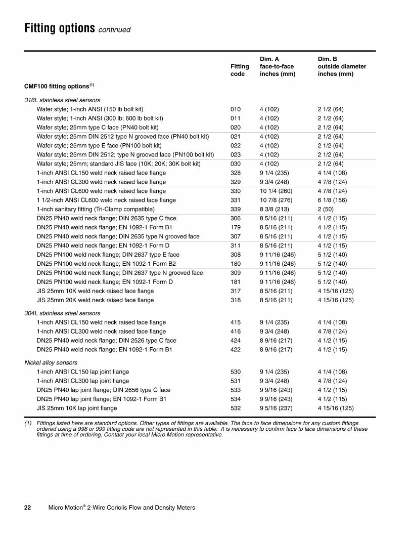
Fitting options continued
Fitting code
Dim. A face-to-faceinches (mm)
Dim. B outside diameterinches (mm)
CMF100 fitting options(1)
(1) Fittings listed here are standard options. Other types of fittings are available. The face to face dimensions for any custom fittings ordered using a 998 or 999 fitting code are not represented in this table. It is necessary to confirm face to face dimensions of these fittings at time of ordering. Contact your local Micro Motion representative.
316L stainless steel sensors
Wafer style; 1-inch ANSI (150 lb bolt kit) 010 4 (102) 2 1/2 (64)
Wafer style; 1-inch ANSI (300 lb; 600 lb bolt kit) 011 4 (102) 2 1/2 (64)
Wafer style; 25mm type C face (PN40 bolt kit) 020 4 (102) 2 1/2 (64)
Wafer style; 25mm DIN 2512 type N grooved face (PN40 bolt kit) 021 4 (102) 2 1/2 (64)
Wafer style; 25mm type E face (PN100 bolt kit) 022 4 (102) 2 1/2 (64)
Wafer style; 25mm DIN 2512; type N grooved face (PN100 bolt kit) 023 4 (102) 2 1/2 (64)
Wafer style; 25mm; standard JIS face (10K; 20K; 30K bolt kit) 030 4 (102) 2 1/2 (64)
1-inch ANSI CL150 weld neck raised face flange 328 9 1/4 (235) 4 1/4 (108)
1-inch ANSI CL300 weld neck raised face flange 329 9 3/4 (248) 4 7/8 (124)
1-inch ANSI CL600 weld neck raised face flange 330 10 1/4 (260) 4 7/8 (124)
1 1/2-inch ANSI CL600 weld neck raised face flange 331 10 7/8 (276) 6 1/8 (156)
1-inch sanitary fitting (Tri-Clamp compatible) 339 8 3/8 (213) 2 (50)
DN25 PN40 weld neck flange; DIN 2635 type C face 306 8 5/16 (211) 4 1/2 (115)
DN25 PN40 weld neck flange; EN 1092-1 Form B1 179 8 5/16 (211) 4 1/2 (115)
DN25 PN40 weld neck flange; DIN 2635 type N grooved face 307 8 5/16 (211) 4 1/2 (115)
DN25 PN40 weld neck flange; EN 1092-1 Form D 311 8 5/16 (211) 4 1/2 (115)
DN25 PN100 weld neck flange; DIN 2637 type E face 308 9 11/16 (246) 5 1/2 (140)
DN25 PN100 weld neck flange; EN 1092-1 Form B2 180 9 11/16 (246) 5 1/2 (140)
DN25 PN100 weld neck flange; DIN 2637 type N grooved face 309 9 11/16 (246) 5 1/2 (140)
DN25 PN100 weld neck flange; EN 1092-1 Form D 181 9 11/16 (246) 5 1/2 (140)
JIS 25mm 10K weld neck raised face flange 317 8 5/16 (211) 4 15/16 (125)
JIS 25mm 20K weld neck raised face flange 318 8 5/16 (211) 4 15/16 (125)
304L stainless steel sensors
1-inch ANSI CL150 weld neck raised face flange 415 9 1/4 (235) 4 1/4 (108)
1-inch ANSI CL300 weld neck raised face flange 416 9 3/4 (248) 4 7/8 (124)
DN25 PN40 weld neck flange; DIN 2526 type C face 424 8 9/16 (217) 4 1/2 (115)
DN25 PN40 weld neck flange; EN 1092-1 Form B1 422 8 9/16 (217) 4 1/2 (115)
Nickel alloy sensors
1-inch ANSI CL150 lap joint flange 530 9 1/4 (235) 4 1/4 (108)
1-inch ANSI CL300 lap joint flange 531 9 3/4 (248) 4 7/8 (124)
DN25 PN40 lap joint flange; DIN 2656 type C face 533 9 9/16 (243) 4 1/2 (115)
DN25 PN40 lap joint flange; EN 1092-1 Form B1 534 9 9/16 (243) 4 1/2 (115)
JIS 25mm 10K lap joint flange 532 9 5/16 (237) 4 15/16 (125)

Micro Motion® 2-Wire Coriolis Flow and Density Meters 23
Fitting options continued
Fitting code
Dim. A face-to-faceinches (mm)
Dim. B outside diameterinches (mm)
CMF200 fitting options(1)
(1) Fittings listed here are standard options. Other types of fittings are available. The face to face dimensions for any custom fittings ordered using a 998 or 999 fitting code are not represented in this table. It is necessary to confirm face to face dimensions of these fittings at time of ordering. Contact your local Micro Motion representative.
316L stainless steel sensors
1 1/2-inch ANSI CL150 weld neck raised face flange 341 22 7/8 (581) 5 (127)
1 1/2-inch ANSI CL300 weld neck raised face flange 342 23 3/8 (594) 6 1/8 (156)
1 1/2-inch ANSI CL600 weld neck raised face flange 343 23 7/8 (606) 6 1/8 (156)
2-inch ANSI CL150 weld neck raised face flange 418 22 7/8 (581) 6 (152)
2-inch ANSI CL300 weld neck raised face flange 419 23 3/8 (594) 6 1/2 (165)
2-inch ANSI CL600 weld neck raised face flange 420 23 5/8 (600) 6 1/2 (165)
1 1/2-inch sanitary fitting (Tri-Clamp compatible) 351 21 3/8 (543) 2 (51)
2-inch sanitary fitting (Tri-Clamp compatible) 352 21 3/8 (543) 2 1/2 (64)
DN40 PN40 weld neck flange; DIN 2635 type C face 381 21 11/16 (551) 5 15/16 (150)
DN40 PN40 weld neck flange; EN 1092-1 Form B1 368 21 9/16 (547) 5 15/16 (150)
DN40 PN40 weld neck flange; DIN 2635 type N grooved face 383 21 11/16 (551) 5 15/16 (150)
DN40 PN40 weld neck flange; EN 1092-1 Form D 312 21 9/16 (547) 5 15/16 (150)
DN40 PN100 weld neck flange; DIN 2637 type E face 377 23 1/8 (587) 6 11/16 (170)
DN40 PN100 weld neck flange; EN 1092-1 Form B2 363 22 7/8 (580) 6 11/16 (170)
DN40 PN100 weld neck flange; DIN 2637 type N grooved face 379 23 1/8 (587) 6 11/16 (170)
DN40 PN100 weld neck flange; EN 1092-1 Form D 366 22 7/8 (580) 6 11/16 (170)
DN50 PN40 weld neck flange; DIN 2635 type C face 382 21 15/16 (557) 6 1/2 (165)
DN50 PN40 weld neck flange; EN 1092-1 Form B1 369 21 3/4 (553) 6 1/2 (165)
DN50 PN40 weld neck flange; DIN 2635 type N grooved face 384 21 15/16 (557) 6 1/2 (165)
DN50 PN40 weld neck flange; EN 1092-1 Form D 316 21 3/4 (553) 6 1/2 (165)
DN50 PN100 weld neck flange; DIN 2637 type E face 378 23 9/16 (598) 7 11/16 (195)
DN50 PN100 weld neck flange; EN 1092-1 Form B2 365 23 5/16 (593) 7 11/16 (195)
DN50 PN100 weld neck flange; DIN 2637 type N grooved face 380 23 9/16 (598) 7 11/16 (195)
DN50 PN100 weld neck flange; EN 1092-1 Form D 367 23 5/16 (593) 7 11/16 (195)
JIS 40mm 10K weld neck raised face flange 385 21 9/16 (548) 5 1/2 (140)
JIS 40mm 20K weld neck raised face flange 387 21 9/16 (548) 5 1/2 (140)
JIS 50mm 10K weld neck raised face flange 386 21 13/16 (554) 6 1/8 (156)
JIS 50mm 20K weld neck raised face flange 388 21 13/16 (554) 6 1/8 (156)

24 Micro Motion® 2-Wire Coriolis Flow and Density Meters
Fitting options continued
Fitting code
Dim. A face-to-faceinches (mm)
Dim. B outside diameterinches (mm)
CMF200 fitting options(1)
(1) Fittings listed here are standard options. Other types of fittings are available. The face to face dimensions for any custom fittings ordered using a 998 or 999 fitting code are not represented in this table. It is necessary to confirm face to face dimensions of these fittings at time of ordering. Contact your local Micro Motion representative.
304L stainless steel sensors
1 1/2-inch ANSI CL150 weld neck raised face flange 441 22 7/8 (581) 5 (127)
1 1/2-inch ANSI CL300 weld neck raised face flange 442 23 3/8 (594) 6 1/8 (156)
2-inch ANSI CL150 weld neck raised face flange 518 22 7/8 (581) 6 (152)
2-inch ANSI CL300 weld neck raised face flange 519 23 1/2 (597) 6 1/2 (165)
DN40 PN40 weld neck flange; DIN 2526 type C face 481 21 11/16 (551) 5 15/16 (150)
DN40 PN40 weld neck flange; EN 1092-1 Form B1 457 21 9/16 (547) 5 15/16 (150)
DN50 PN40 weld neck raised face flange; DIN 2526 type C face 482 21 15/16 (557) 6 1/2 (165)
DN50 PN40 weld neck raised face flange; EN 1092-1 Form B1 458 21 3/4 (553) 6 1/2 (165)
Nickel alloy sensors
1 1/2-inch ANSI CL150 lap joint flange 540 22 7/8 (581) 5 (127)
1 1/2-inch ANSI CL300 lap joint flange 541 23 3/8 (594) 6 1/8 (156)
2-inch ANSI CL150 lap joint flange 544 22 7/8 (581) 6 (152)
2-inch ANSI CL300 lap joint flange 545 23 3/8 (594) 6 1/2 (165)
DN40 PN40 lap joint flange; DIN 2656 type C face 543 21 11/16 (551) 5 15/16 (150)
DN40 PN40 lap joint flange; EN 1092-1 Form B1 548 21 11/16 (551) 5 15/16 (150)
DN50 PN40 lap joint flange; DIN 2656 type C face 547 21 15/16 (557) 6 1/2 (165)
DN50 PN40 lap joint flange; EN 1092-1 Form B1 549 21 15/16 (557) 6 1/2 (165)
JIS 40mm 10K lap joint flange 542 21 9/16 (548) 5 1/2 (140)
JIS 50mm 10K lap joint flange 546 21 13/16 (554) 6 1/8 (155)
Micro Motion® 2-Wire Coriolis Flow and Density Meters 25
Fitting options continued
Fitting code
Dim. A face-to-faceinches (mm)
Dim. B outside diameterinches (mm)
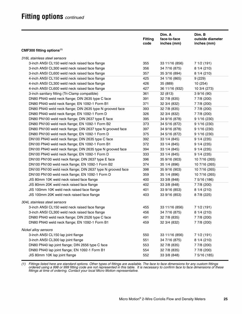
CMF300 fitting options(1)
(1) Fittings listed here are standard options. Other types of fittings are available. The face to face dimensions for any custom fittings ordered using a 998 or 999 fitting code are not represented in this table. It is necessary to confirm face to face dimensions of these fittings at time of ordering. Contact your local Micro Motion representative.
316L stainless steel sensors3-inch ANSI CL150 weld neck raised face flange 355 33 11/16 (856) 7 1/2 (191)3-inch ANSI CL300 weld neck raised face flange 356 34 7/16 (875) 8 1/4 (210)3-inch ANSI CL600 weld neck raised face flange 357 35 3/16 (894) 8 1/4 (210)4-inch ANSI CL150 weld neck raised face flange 425 34 1/16 (865) 9 (229)4-inch ANSI CL300 weld neck raised face flange 426 35 (889) 10 (254)4-inch ANSI CL600 weld neck raised face flange 427 36 11/16 (932) 10 3/4 (273)3-inch sanitary fitting (Tri-Clamp compatible) 361 32 (813) 3 9/16 (90)DN80 PN40 weld neck flange; DIN 2635 type C face 391 32 7/8 (835) 7 7/8 (200)DN80 PN40 weld neck flange; EN 1092-1 Form B1 371 32 3/4 (832) 7 7/8 (200)DN80 PN40 weld neck flange; DIN 2635 type N grooved face 393 32 7/8 (835) 7 7/8 (200)DN80 PN40 weld neck flange; EN 1092-1 Form D 326 32 3/4 (832) 7 7/8 (200)DN80 PN100 weld neck flange; DIN 2637 type E face 395 34 9/16 (878) 9 1/16 (230)DN80 PN100 weld neck flange; EN 1092-1 Form B2 373 34 5/16 (872) 9 1/16 (230)DN80 PN100 weld neck flange; DIN 2637 type N grooved face 397 34 9/16 (878) 9 1/16 (230)DN80 PN100 weld neck flange; EN 1092-1 Form D 375 34 5/16 (872) 9 1/16 (230)DN100 PN40 weld neck flange; DIN 2635 type C face 392 33 1/4 (845) 9 1/4 (235)DN100 PN40 weld neck flange; EN 1092-1 Form B1 372 33 1/4 (845) 9 1/4 (235)DN100 PN40 weld neck flange; DIN 2635 type N grooved face 394 33 1/4 (845) 9 1/4 (235)DN100 PN40 weld neck flange; EN 1092-1 Form D 333 33 1/4 (845) 9 1/4 (235)DN100 PN100 weld neck flange; DIN 2637 type E face 396 35 9/16 (903) 10 7/16 (265)DN100 PN100 weld neck flange; EN 1092-1 Form B2 374 35 1/4 (896) 10 7/16 (265)DN100 PN100 weld neck flange; DIN 2637 type N grooved face 398 35 9/16 (903) 10 7/16 (265)DN100 PN100 weld neck flange; EN 1092-1 Form D 359 35 1/4 (896) 10 7/16 (265)JIS 80mm 10K weld neck raised face flange 400 33 3/8 (848) 7 5/16 (186)JIS 80mm 20K weld neck raised face flange 402 33 3/8 (848) 7 7/8 (200)JIS 100mm 10K weld neck raised face flange 401 33 9/16 (853) 8 1/4 (210)JIS 100mm 20K weld neck raised face flange 403 33 9/16 (853) 8 7/8 (225)
304L stainless steel sensors3-inch ANSI CL150 weld neck raised face flange 455 33 11/16 (856) 7 1/2 (191)3-inch ANSI CL300 weld neck raised face flange 456 34 7/16 (875) 8 1/4 (210)DN80 PN40 weld neck flange; DIN 2526 type C face 491 32 7/8 (835) 7 7/8 (200)DN80 PN40 weld neck flange; EN 1092-1 Form B1 459 32 3/4 (832) 7 7/8 (200)
Nickel alloy sensors3-inch ANSI CL150 lap joint flange 550 33 11/16 (856) 7 1/2 (191)3-inch ANSI CL300 lap joint flange 551 34 7/16 (875) 8 1/4 (210)DN80 PN40 lap joint flange; DIN 2656 type C face 553 32 7/8 (835) 7 7/8 (200)DN80 PN40 lap joint flange; EN 1092-1 Form B1 554 32 7/8 (835) 7 7/8 (200)JIS 80mm 10K lap joint flange 552 33 3/8 (848) 7 5/16 (185)

26 Micro Motion® 2-Wire Coriolis Flow and Density Meters
Fitting options continued
Fitting code
Dim. A face-to-faceinches (mm)
Dim. B outside diameterinches (mm)
CMF400 fitting options(1)
(1) Fittings listed here are standard options. Other types of fittings are available. The face to face dimensions for any custom fittings ordered using a 998 or 999 fitting code are not represented in this table. It is necessary to confirm face to face dimensions of these fittings at time of ordering. Contact your local Micro Motion representative.
316L stainless steel sensors
4-inch ANSI CL150 weld neck raised face flange 435 40 3/16 (1021) 9 (229)
4-inch ANSI CL300 weld neck raised face flange 436 41 (1041) 10 (254)
4-inch ANSI CL600 weld neck raised face flange 437 42 11/16 (1084) 10 3/4 (273)
6-inch ANSI CL150 weld neck raised face flange 451 40 5/16 (1024) 11 (279)
6-inch ANSI CL300 weld neck raised face flange 452 41 5/16 (1049) 12 1/2 (318)
6-inch ANSI CL600 weld neck raised face flange 453 43 1/2 (1105) 14 (356)
DN100 PN40 weld neck flange; DIN 2635 type C face 460 39 5/16 (999) 9 1/4 (235)
DN100 PN40 weld neck flange; EN 1092-1 Form B1 443 39 5/16 (999) 9 1/4 (235)
DN100 PN40 weld neck flange; DIN 2635 type N grooved face 462 39 5/16 (999) 9 1/4 (235)
DN100 PN40 weld neck flange; EN 1092-1 Form D 480 39 5/16 (999) 9 1/4 (235)
DN100 PN100 weld neck flange; DIN 2637 type E face 464 41 5/16 (1049) 10 7/16 (265)
DN100 PN100 weld neck flange; EN 1092-1 Form B2 445 41 5/16 (1049) 10 7/16 (265)
DN100 PN100 weld neck flange; DIN 2637 type N grooved face 466 41 5/16 (1049) 10 7/16 (265)
DN100 PN100 weld neck flange; EN 1092-1 Form D 447 41 5/16 (1049) 10 7/16 (265)
DN150 PN40 weld neck flange; DIN 2635 type C face 461 39 5/8 (1006) 11 13/16 (300)
DN150 PN40 weld neck flange; EN 1092-1 Form B1 444 40 1/16 (1018) 11 13/16 (300)
DN150 PN40 weld neck flange; DIN 2635 type N grooved face 463 39 5/8 (1006) 11 13/16 (300)
DN150 PN40 weld neck flange; EN 1092-1 Form D 478 40 1/16 (1018) 11 13/16 (300)
DN150 PN100 weld neck flange; DIN 2637 type E face 465 41 15/16 (1065) 14 (355)
DN150 PN100 weld neck flange; EN 1092-1 Form B2 446 43 1/4 (1099) 14 (355)
DN150 PN100 weld neck flange; DIN 2637 type N grooved face 467 41 15/16 (1065) 14 (355)
DN150 PN100 weld neck flange; EN 1092-1 Form D 448 43 1/4 (1099) 14 (355)
JIS 100mm 10K weld neck raised face flange 470 39 5/16 (999) 8 1/4 (210)
JIS 100mm 20K weld neck raised face flange 472 39 13/16 (1011) 8 7/8 (225)
JIS 150mm 10K weld neck raised face flange 471 39 5/8 (1006) 11 (280)
JIS 150mm 20K weld neck raised face flange 473 40 1/8 (1018) 12 (305)
Micro Motion® 2-Wire Coriolis Flow and Density Meters 27
Fitting options continued
Fitting code
Dim. A face-to-faceinches (mm)
Dim. B outside diameterinches (mm)
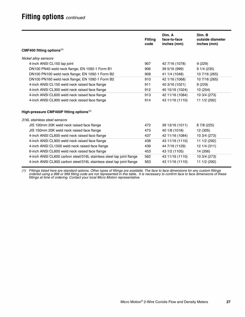
CMF400 fitting options(1)
(1) Fittings listed here are standard options. Other types of fittings are available. The face to face dimensions for any custom fittings ordered using a 998 or 999 fitting code are not represented in this table. It is necessary to confirm face to face dimensions of these fittings at time of ordering. Contact your local Micro Motion representative.
Nickel alloy sensors
4-inch ANSI CL150 lap joint 907 42 7/16 (1078) 9 (229)
DN100 PN40 weld neck flange; EN 1092-1 Form B1 906 39 5/16 (999) 9 1/4 (235)
DN100 PN100 weld neck flange; EN 1092-1 Form B2 908 41 1/4 (1048) 10 7/16 (265)
DN100 PN160 weld neck flange; EN 1092-1 Form B2 910 42 1/16 (1068) 10 7/16 (265)
4-inch ANSI CL150 weld neck raised face flange 911 40 3/16 (1021) 9 (229)
4-inch ANSI CL300 weld neck raised face flange 912 40 15/16 (1024) 10 (254)
4-inch ANSI CL600 weld neck raised face flange 913 42 11/16 (1084) 10 3/4 (273)
4-inch ANSI CL900 weld neck raised face flange 914 43 11/16 (1110) 11 1/2 (292)
High-pressure CMF400P fitting options(1)
316L stainless steel sensors
JIS 100mm 20K weld neck raised face flange 472 39 13/16 (1011) 8 7/8 (225)
JIS 150mm 20K weld neck raised face flange 473 40 1/8 (1018) 12 (305)
4-inch ANSI CL600 weld neck raised face flange 437 42 11/16 (1084) 10 3/4 (273)
4-inch ANSI CL900 weld neck raised face flange 438 43 11/16 (1110) 11 1/2 (292)
4-inch ANSI CL1500 weld neck raised face flange 439 44 7/16 (1129) 12 1/4 (311)
6-inch ANSI CL600 weld neck raised face flange 453 43 1/2 (1105) 14 (356)
4-inch ANSI CL600 carbon steel/316L stainless steel lap joint flange 562 43 11/16 (1110) 10 3/4 (273)
4-inch ANSI CL900 carbon steel/316L stainless steel lap joint flange 563 43 11/16 (1110) 11 1/2 (292)
28 Micro Motion® 2-Wire Coriolis Flow and Density Meters
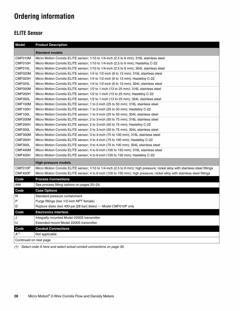
Ordering information
ELITE Sensor
Model Product Description
Standard models
CMF010M Micro Motion Coriolis ELITE sensor; 1/10 to 1/4-inch (2.5 to 6 mm); 316L stainless steel
CMF010H Micro Motion Coriolis ELITE sensor; 1/10 to 1/4-inch (2.5 to 6 mm); Hastelloy C-22
CMF010L Micro Motion Coriolis ELITE sensor; 1/10 to 1/4-inch (2.5 to 6 mm); 304L stainless steel
CMF025M Micro Motion Coriolis ELITE sensor; 1/4 to 1/2-inch (6 to 13 mm); 316L stainless steel
CMF025H Micro Motion Coriolis ELITE sensor; 1/4 to 1/2-inch (6 to 13 mm); Hastelloy C-22
CMF025L Micro Motion Coriolis ELITE sensor; 1/4 to 1/2-inch (6 to 13 mm); 304L stainless steel
CMF050M Micro Motion Coriolis ELITE sensor; 1/2 to 1-inch (13 to 25 mm); 316L stainless steel
CMF050H Micro Motion Coriolis ELITE sensor; 1/2 to 1-inch (13 to 25 mm); Hastelloy C-22
CMF050L Micro Motion Coriolis ELITE sensor; 1/2 to 1-inch (13 to 25 mm); 304L stainless steel
CMF100M Micro Motion Coriolis ELITE sensor; 1 to 2-inch (25 to 50 mm); 316L stainless steel
CMF100H Micro Motion Coriolis ELITE sensor; 1 to 2-inch (25 to 50 mm); Hastelloy C-22
CMF100L Micro Motion Coriolis ELITE sensor; 1 to 2-inch (25 to 50 mm); 304L stainless steel
CMF200M Micro Motion Coriolis ELITE sensor; 2 to 3-inch (50 to 75 mm); 316L stainless steel
CMF200H Micro Motion Coriolis ELITE sensor; 2 to 3-inch (50 to 75 mm); Hastelloy C-22
CMF200L Micro Motion Coriolis ELITE sensor; 2 to 3-inch (50 to 75 mm); 304L stainless steel
CMF300M Micro Motion Coriolis ELITE sensor; 3 to 4-inch (75 to 100 mm); 316L stainless steel
CMF300H Micro Motion Coriolis ELITE sensor; 3 to 4-inch (75 to 100 mm); Hastelloy C-22
CMF300L Micro Motion Coriolis ELITE sensor; 3 to 4-inch (75 to 100 mm); 304L stainless steel
CMF400M Micro Motion Coriolis ELITE sensor; 4 to 6-inch (100 to 150 mm); 316L stainless steel
CMF400H Micro Motion Coriolis ELITE sensor; 4 to 6-inch (100 to 150 mm); Hastelloy C-22
High-pressure models
CMF010P Micro Motion Coriolis ELITE sensor; 1/10 to 1/4-inch (2.5 to 6 mm); high pressure; nickel alloy with stainless steel fittings
CMF400P Micro Motion Coriolis ELITE sensor; 4 to 6-inch (100 to 150 mm); high pressure; nickel alloy with stainless steel fittings
Code Process Connections
### See process fitting options on pages 20–24.
Code Case Options
N Standard pressure containment
P Purge fittings (two 1/2-inch NPT female)
D Rupture disks (two 400-psi [28 bar] disks) — Model CMF010P only
Code Electronics Interface
J Integrally mounted Model 2200S transmitter
U Extended mount Model 2200S transmitter
Code Conduit Connections
A(1)
(1) Select code A here and select actual conduit connections on page 30.
Not applicable
Continued on next page
Micro Motion® 2-Wire Coriolis Flow and Density Meters 29
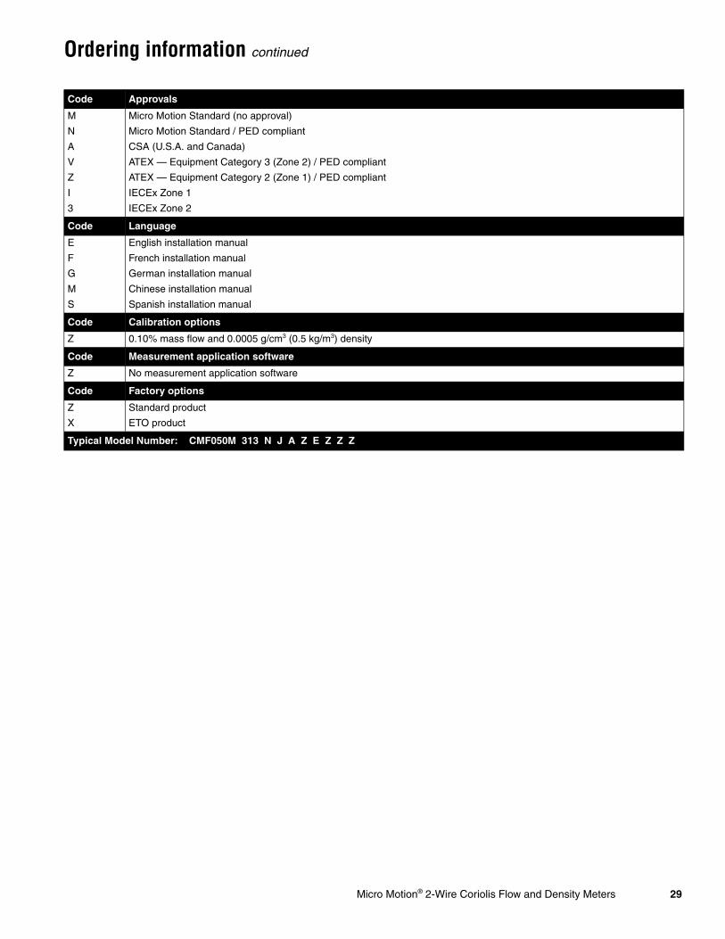
Ordering information continued
Code Approvals
M Micro Motion Standard (no approval)
N Micro Motion Standard / PED compliant
A CSA (U.S.A. and Canada)
V ATEX — Equipment Category 3 (Zone 2) / PED compliant
Z ATEX — Equipment Category 2 (Zone 1) / PED compliant
I IECEx Zone 1
3 IECEx Zone 2
Code Language
E English installation manual
F French installation manual
G German installation manual
M Chinese installation manual
S Spanish installation manual
Code Calibration options
Z 0.10% mass flow and 0.0005 g/cm3 (0.5 kg/m3) density
Code Measurement application software
Z No measurement application software
Code Factory options
Z Standard product
X ETO product
Typical Model Number: CMF050M 313 N J A Z E Z Z Z

30 Micro Motion® 2-Wire Coriolis Flow and Density Meters
Ordering information continued
Model 2200S transmitter
Model Product description
2200S Micro Motion Coriolis 2-wire MVD transmitter
Code Mounting/housing material
I Integral-mount transmitter / Polyurethane-painted aluminum
J(1)
(1) Not recommended for truck-mount.
Integral-mount transmitter / 316L stainless steel
Code Output options / Power supply
H One 12–20 mA output with HART/Bell 202
K One 4–20 mA output with HART/Bell 202, supplied with Micro Motion adapter-barrier
Code I/O terminations
1 Compression screw terminals
Code Display
1 Dual-line display for process variables and totalizer reset, glass lens
4(2)
(2) Available only with Approval Code M.
Dual-line display for process variables and totalizer reset, non-glass lens
Code Conduit connections
B 1/2-inch NPT — no gland
C 1/2-inch NPT with brass/nickel cable gland
D 1/2-inch NPT with stainless steel cable gland
E M20 — no gland
F M20 with brass/nickel cable gland
G M20 with stainless steel cable gland
Code Approvals
M Micro Motion standard (no approval)
A CSA (U.S.A. and Canada)
Z ATEX Zone 1
L ATEX Zone 2
I IECEx Zone 1
3 IECEx Zone 2
Code Language
E English installation manual and English configuration manual
F French installation manual and French configuration manual
G German installation manual and German configuration manual
M Chinese installation manual and Chinese configuration manual
S Spanish installation manual and Spanish configuration manual
Code Software options 1
Z No software options 1
Code Software options 2
Z No software options 2
Code Factory options
Z Standard product
Typical model number: 2200S I H 1 1 B Z E Z Z Z

Micro Motion® 2-Wire Coriolis Flow and Density Meters 31
Micro Motion—The undisputed leader in flow and density measurement
WWW.micromotion.com
World-leading Micro Motion measurement solutions from Emerson Process Management deliver what you need most:
Technology leadershipMicro Motion introduced the first reliable Coriolis meter in 1977. Since that time, our ongoing product development has enabled us to provide the highest performing measurement devices available.
Product breadthFrom compact, drainable process control to high flow rate fiscal transfer—look no further than Micro Motion for the widest range of measurement solutions.
Unparalleled valueBenefit from expert phone, field, and application service and support made possible by more than 600,000 meters installed worldwide and over 30 years of flow and density measurement experience.
© 2009 Micro Motion, Inc. All rights reserved. Micro Motion is committed to continuous product improvement. As a result, all specifications are subject to change without notice. ELITE and ProLink are registered trademarks, and MVD and MVD Direct Connect are trademarks of Micro Motion, Inc., Boulder, Colorado. Micro Motion is a registered trade name of Micro Motion, Inc., Boulder, Colorado. The Micro Motion and Emerson logos are trademarks and service marks of Emerson Electric Co. All other trademarks are property of their respective owners.
For a complete list of contact information and web sites, please visit: www.emersonprocess.com/home/contacts/global