2 Wago Signal Splitter (2)
2
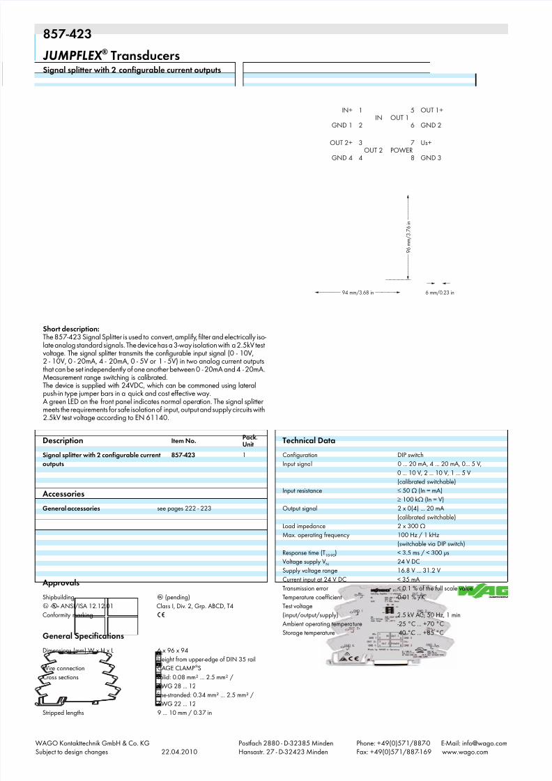
857-423 3 206 JUMPFLEX ® Transducers Signal splitter with 2 configurable current outputs OUT 1 IN POWER 5 6 1 2 3 4 7 8 OUT 1+ GND 2 Us+ GND 3 IN+ GND 1 OUT 2+ GND 4 OUT 2 <_________ 94 mm/3.68 in _________> 6 mm/0.23 in 9 6 m m / 3 . 7 6 i n > ____________ _> _ > Short description: The 857-423 Signal Splitter is used to convert, amplify , filter and electrically iso- late analog standard signals. The device has a 3-way isolation with a 2.5kV test voltage. The signal splitter transmits the configurable input signal (0 - 10V, 2 - 10V, 0 - 20mA, 4 - 20mA, 0 - 5V or 1 - 5V) in two analog current outputs that can be set independently of one another between 0 - 20mA and 4 - 20mA. Measurement range switching is calibrated. The device is supplied with 24VDC, which can be commoned using lateral push-in type jumper bars in a quick and cost effective way. A green LED on the front panel indicates normal opera tion. The signal splitter meets the requirements for safe isolation of input, output and supply circuits with 2.5kV test voltage according to EN 61140. Description Item No. Pack. Unit Signal splitter with 2 configurable current outputs 857-423 1 Accessories General accessories see pages 222 - 223 Approvals Shipbuilding g (pending) 4 r ANSI/ISA 12.12.01 Class I, Div. 2, Grp. ABCD, T4 Conformity marking 1 General Specifications Dimensions (mm) W x H x L 6 x 96 x 94 Height from upper-edge of DIN 35 rail Wire connection CAGE CLAMP ® S Cross sections solid: 0.08 mm² ... 2.5 mm² / AWG 28 ... 12 fine-stranded: 0.34 mm² ... 2.5 mm² / AWG 22 ... 12 Stripped lengths 9 ... 10 mm / 0.37 in Technical Data Configuration DIP switch Input signal 0 ... 20 mA, 4 ... 20 mA, 0... 5 V, 0 ... 10 V, 2 ... 10 V, 1 ... 5 V (calibrated switchable) Input resistance 50 Ω (In = mA) 100 kΩ (In = V) Output signal 2 x 0(4) ... 20 mA (calibrated switchable) Load impedance 2 x 300 Ω Max. operating frequency 100 Hz / 1 kHz (switchable via DIP switch) Response time (T 10-90 ) < 3.5 ms / < 300 µs Voltage supply V N 24 V DC Supply voltage range 16.8 V ... 31.2 V Current input at 24 V DC < 35 mA Transmission error < 0.1 % of the full scale value Temperature coef ficient 0.01 % /K Test voltage (input/output/supply) 2.5 kV AC, 50 Hz, 1 min Ambient operating temperature -25 °C ... +70 °C Storage temperature -40 °C ... +85 °C WAGO Kontakttechnik GmbH & Co. KG Subject to design changes 22.04.2010 Postfach 2880 - D-32385 Minden Hansastr. 27 - D-32423 Minden Phone: +49(0)571/887 -0 E-Mail: [email protected] Fax: +49(0)571/887 -169 www.wago.com
Transcript of 2 Wago Signal Splitter (2)
857-423
3206
JUMPFLEX ® Transducers
Signal splitter with 2 configurable current outputs
OUT 1IN
POWER
5
6
1
2
3
4
7
8
OUT 1+
GND 2
Us+
GND 3
IN+
GND 1
OUT 2+
GND 4OUT 2
<_________ 94 mm/3.68 in _________> 6 mm/0.23 in
< _ _ _ _ _ _ _ _ _
9 6
m m / 3 . 7
6 i n _ _ _ _ _ _ _ _ _ >
____________ _>
_ >
Short description:The 857-423 Signal Splitter is used to convert, amplify, filter and electrically iso-late analog standard signals. The device has a 3-way isolation with a 2.5kV testvoltage. The signal splitter transmits the configurable input signal (0 - 10V,2 - 10V, 0 - 20mA, 4 - 20mA, 0 - 5V or 1 - 5V) in two analog current outputsthat can be set independently of one another between 0 - 20mA and 4 - 20mA.Measurement range switching is calibrated.The device is supplied with 24VDC, which can be commoned using lateralpush-in type jumper bars in a quick and cost effective way.A green LED on the front panel indicates normal operation. The signal splittermeets the requirements for safe isolation of input, output and supply circuits with2.5kV test voltage according to EN 61140.
Description Item No.Pack.Unit
Signal splitter with 2 configurable current
outputs
857-423 1
Accessories
General accessories see pages 222 - 223
Approvals
Shipbuilding g (pending)
4 r ANSI/ISA 12.12.01 Class I, Div. 2, Grp. ABCD, T4
Conformity marking 1
General Specifications
Dimensions (mm) W x H x L 6 x 96 x 94
Height from upper-edge of DIN 35 rail
Wire connection CAGE CLAMP®S
Cross sections solid: 0.08 mm² ... 2.5 mm² /
AWG 28 ... 12
fine-stranded: 0.34 mm² ... 2.5 mm² /
AWG 22 ... 12
Stripped lengths 9 ... 10 mm / 0.37 in
Technical Data
Configuration DIP switch
Input signal 0 ... 20 mA, 4 ... 20 mA, 0... 5 V,
0 ... 10 V, 2 ... 10 V, 1 ... 5 V
(calibrated switchable)
Input resistance 50 Ω (In = mA)
100 kΩ (In = V)
Output signal 2 x 0(4) ... 20 mA
(calibrated switchable)
Load impedance 2 x 300 Ω
Max. operating frequency 100 Hz / 1 kHz
(switchable via DIP switch)
Response time (T10-90) < 3.5 ms / < 300 µs
Voltage supply VN 24 V DC
Supply voltage range 16.8 V ... 31.2 V
Current input at 24 V DC < 35 mA
Transmission error < 0.1 % of the full scale value
Temperature coefficient 0.01 % /K
Test voltage
(input/output/supply) 2.5 kV AC, 50 Hz, 1 min
Ambient operating temperature -25 °C ... +70 °C
Storage temperature -40 °C ... +85 °C
WAGO Kontakttechnik GmbH & Co. KGSubject to design changes 22.04.2010
Postfach 2880 - D-32385 MindenHansastr. 27 - D-32423 Minden
Phone: +49(0)571/887-0 E-Mail: [email protected]: +49(0)571/887-169 www.wago.com

3
DIP Switch Adjustability ▯ = ON
DIP Switch S1 (6-fold)
Input Signal Max. Operating Frequency Output 1 Output 2
1 2 3 4 5 6
▯ 0 … 20 mA f max. approx. 1 kHz 0 … 20 mA 0 … 20 mA
▯ ▯ 4 … 20 mA ▯ f max.
< 100 Hz ▯ 4 … 20 mA ▯ 4 … 20 mA
▯ 0 … 10 V
▯ ▯ 2 … 10 V
0 … 5 V
▯ 1 … 5 V
Default Settings
- Input: 0 ... 20 mA
- Output 1: 0 … 20 mA
- Output 2: 0 … 20 mA
- Max. Operating Frequency: < 100 Hz
857-423
WAGO Kontakttechnik GmbH & Co. KGSubject to design changes 22.04.2010
Postfach 2880 - D-32385 MindenHansastr. 27 - D-32423 Minden
Phone: +49(0)571/887-0 E-Mail: [email protected]: +49(0)571/887-169 www.wago.com