safetycontrol.ind.br · 2 WAGO-I/O-SYSTEM 750 750-508 2DO 24V DC 2.0A, diagnostics Manual Version...
52
Pos: 2 /Dokumentation allgemein/Einband/Einband Deckblatt @ 9\mod_1285229289866_0.doc @ 64941 @ @ 1 Manual WAGO-I/O-SYSTEM 750 2DO 24V DC 2.0A, diagnostics 750-508 2-Channel Digital Output Module DC 24 V, short- circuit protected; high-side switching, with diagnostics Version 1.2.0 Pos: 3 /Alle Serien (Allgemeine Module)/Hinweise zur Dokumentation/Impressum - allgemeine Angaben, Anschriften, Telefonnummern und E-Mail-Adressen @ 3\mod_1219151118203_21.doc @ 21060 @ @ 1
Transcript of safetycontrol.ind.br · 2 WAGO-I/O-SYSTEM 750 750-508 2DO 24V DC 2.0A, diagnostics Manual Version...

Pos: 2 /Dokumentation allgemein/Einband/Einband Deckblatt @ 9\mod_1285229289866_0.doc @ 64941 @ @ 1
Manual
WAGO-I/O-SYSTEM 7502DO 24V DC 2.0A, diagnostics
750-5082-Channel Digital Output Module DC 24 V, short-
circuit protected; high-side switching, with diagnostics
Version 1.2.0
Pos: 3 /Alle Serien (Allgemeine Module)/Hinweise zur Dokumentation/Impressum - allgemeine Angaben, Anschriften, Telefonnummern und E-Mail-Adressen @ 3\mod_1219151118203_21.doc @ 21060 @ @ 1
2 WAGO-I/O-SYSTEM 750 750-508 2DO 24V DC 2.0A, diagnostics
Manual Version 1.2.0
© 2011 by WAGO Kontakttechnik GmbH & Co. KG All rights reserved.
WAGO Kontakttechnik GmbH & Co. KG
Hansastraße 27 D-32423 Minden
Phone: +49 (0) 571/8 87 – 0 Fax: +49 (0) 571/8 87 – 1 69
E-Mail: [email protected]
Web: http://www.wago.com
Technical Support
Phone: +49 (0) 571/8 87 – 5 55 Fax: +49 (0) 571/8 87 – 85 55
E-Mail: [email protected]
Every conceivable measure has been taken to ensure the accuracy and completeness of this documentation. However, as errors can never be fully excluded, we always appreciate any information or suggestions for improving the documentation.
E-Mail: [email protected]
We wish to point out that the software and hardware terms as well as the trademarks of companies used and/or mentioned in the present manual are generally protected by trademark or patent.
=== Ende der Liste für Textmarke Einband_vorne ===

WAGO-I/O-SYSTEM 750 Table of Contents 3 750-508 2DO 24V DC 2.0A, diagnostics Po
s: 5 /Dokumentation allgemein/Verzeichnisse/Inhaltsverzeichnis - Überschrift 1 und Verzeichnis @ 3\mod_1219151230875_21.doc @ 21063 @ @ 1
Table of Contents
1 Notes about this Documentation................................................................. 5
1.1 Validity of this Documentation................................................................. 5 1.2 Copyright................................................................................................... 5 1.3 Symbols..................................................................................................... 7 1.4 Number Notation....................................................................................... 9 1.5 Font Conventions ...................................................................................... 9
2 Important Notes ......................................................................................... 10
2.1 Legal Bases ............................................................................................. 10 2.1.1 Subject to Changes ............................................................................. 10 2.1.2 Personnel Qualifications..................................................................... 10 2.1.3 Use of the 750 Series in Compliance with Underlying Provisions .... 10 2.1.4 Technical Condition of Specified Devices ......................................... 11 2.2 Safety Advice (Precautions).................................................................... 12
3 Use as replacement for 750-507 ................................................................ 14
4 Device Description ..................................................................................... 15
4.1 View ........................................................................................................ 17 4.2 Connectors............................................................................................... 18 4.2.1 Data Contacts/Internal Bus................................................................. 18 4.2.2 Power Contacts/Field Supply ............................................................. 19 4.2.3 CAGE CLAMP® Connections ........................................................... 20 4.3 Display Elements .................................................................................... 21 4.4 Operating Elements ................................................................................. 21 4.5 Schematic Diagram ................................................................................. 22 4.6 Technical Data ........................................................................................ 23 4.6.1 Device Data ........................................................................................ 23 4.6.2 Power Supply...................................................................................... 23 4.6.3 Communication .................................................................................. 23 4.6.4 Outputs ............................................................................................... 24 4.7 Approvals ................................................................................................ 25 4.8 Standards and Guidelines........................................................................ 26
5 Assembly ..................................................................................................... 27
5.1 Assembly Sequence ................................................................................ 27 5.2 Inserting and Removing Devices ............................................................ 28 5.2.1 Inserting I/O Module .......................................................................... 28 5.2.2 Removing the I/O Module.................................................................. 29
6 Connect Devices ......................................................................................... 30
6.1 Connecting a conductor to the CAGE CLAMP® .................................... 30 6.2 Connection Examples.............................................................................. 31 6.2.1 2-Conductor Connection, ungrounded ............................................... 31 6.2.2 2-Conductor Connection, grounded ................................................... 31 6.2.3 3-Conductor Connection, ungrounded ............................................... 32 6.2.4 3-Conductor Connection, grounded ................................................... 32
7 Process Image ............................................................................................. 33
Manual Version 1.2.0

4 Table of Contents WAGO-I/O-SYSTEM 750 750-508 2DO 24V DC 2.0A, diagnostics
Manual Version 1.2.0
8 Using Interference-Free Variations of I/O Modules in Safety Related Applications ................................................................................................ 34
8.1 Important Notes....................................................................................... 35 8.2 Connecting the IO Module to Safety Switching Devices or Safety
Modules................................................................................................... 36 8.2.1 General Structure................................................................................ 36 8.2.2 Examples of Connection..................................................................... 37
9 Use in Hazardous Environments .............................................................. 39
9.1 Identification ........................................................................................... 40 9.1.1 For Europe according to CENELEC and IEC.................................... 40 9.1.2 For America according to NEC 500................................................... 43 9.2 Installation Regulations........................................................................... 44 9.2.1 Special Conditions for Safe Operation of the ATEX and IEC Ex (acc.
DEMKO 08 ATEX 142851X and IECEx PTB 07.0064)................... 45 9.2.2 Special conditions for safe use (ATEX Certificate TÜV 07 ATEX
554086 X)........................................................................................... 46 9.2.3 Special conditions for safe use (IEC-Ex Certificate TUN 09.0001 X)47 9.2.4 ANSI/ISA 12.12.01 ............................................................................ 48
List of Figures ...................................................................................................... 49
List of Tables........................................................................................................ 50
=== Ende der Liste für Textmarke Verzeichnis_vorne ===

WAGO-I/O-SYSTEM 750 Notes about this Documentation 5 750-508 2DO 24V DC 2.0A, diagnostics Po
s: 7 /Alle Serien (Allgemeine Module)/Überschriften für alle Serien/Hinweise zur Dokumentation - Überschrift 1 @ 4\mod_1237987661750_21.doc @ 29029 @ 1 @ 1
1 Notes about this Documentation Po
s: 8 /Alle Serien (Allgemeine Module)/Hinweise zur Dokumentation/Hinweis: Dokumentation aufbewahren @ 4\mod_1237987339812_21.doc @ 29026 @ @ 1
Keep this documentation! The operating instructions are part of the product and shall be kept for the entire lifetime of the device. They shall be transferred to each subsequent owner or user of the device. Care must also be taken to ensure that any supplement to these instructions are included, if applicable.
s: 9 /Serie 750 (WAGO-I/O-SYSTEM)/Hinweise zur Dokumentation/Gültigkeitsbereich Dokumentation Busklemme 750-xxxx, aufgelistete Varianten @ 10\mod_1301406801733_21.doc @ 71350 @ 2 @ 1 Po
1.1 Validity of this Documentation
This documentation is only applicable to the I/O module 750-508 (2DO 24V DC 2.0A, diagnostics) of the WAGO-I/O-SYSTEM 750 series and the variants listed in the table below.
Po
s: 10 /Serie 750 (WAGO-I/O-SYSTEM)/Hinweise zur Dokumentation/Variantenlisten/Variantenliste - 750-xxx - Grundausführung und Variante /000-800 (rückwirkungsfrei) @ 10\mod_1302671594038_21.doc @ 71910 @ @ 1
Table 1: Variants
Item Number/Variant Designation 750-508 2DO 24V DC 2.0A, diagnostics2DO 24V DC 2.0A,
diagnostics 750-508/000-800 2DO 24V DC 2.0A, diagnostics/R
Po
s: 11 /Serie 750 (WAGO-I/O-SYSTEM)/Hinweise zur Dokumentation/Hinweise/Hinweis: Gültigkeit der Angaben für aufgelistete Varianten @ 9\mod_1281520778141_21.doc @ 63085 @ @ 1
Documentation Validity for Variants Unless otherwise specified, basic version 750-508data also applies to listed variants.
men 750-xxxx @ 4\mod_1237986979656_21.doc @ 29023 @ @ 1
The I/O module 750-508 shall only be installed and operated according to the instructions in this manual and in the manual for the used fieldbus coupler/controller.
Po
s: 12 /Serie 750 (WAGO-I/O-SYSTEM)/Hinweise zur Dokumentation/Hinweise/Achtung: Hinweis zur Dokumentation Busklem
Consider power layout of the WAGO-I/O-SYSTEM 750! In addition to these operating instructions, you will also need the manual for the used fieldbus coupler/controller, which can be downloaded at www.wago.com. There, you can obtain important information including information on electrical isolation, system power and supply specifications.
s: 13.1 /Alle Serien (Allgemeine Module)/Hinweise zur Dokumentation/Urheberschutz ausführlich @ 4\mod_1235565145234_21.doc @ 27691 @ 2 @ 1 Po
1.2 Copyright
This Manual, including all figures and illustrations, is copyright-protected. Any further use of this Manual by third parties that violate pertinent copyright provisions is prohibited. Reproduction, translation, electronic and phototechnical filing/archiving (e.g., photocopying) as well as any amendments require the
Manual Version 1.2.0

6 Notes about this Documentation WAGO-I/O-SYSTEM 750 750-508 2DO 24V DC 2.0A, diagnostics
written consent of WAGO Kontakttechnik GmbH & Co. KG, Minden, Germany. Non-observance will involve the right to assert damage claims.
Po
s: 13.2 /Dokumentation allgemein/Gliederungselemente/---Seitenwechsel--- @ 3\mod_1221108045078_0.doc @ 21810 @ @ 1
Manual Version 1.2.0

WAGO-I/O-SYSTEM 750 Notes about this Documentation 7 750-508 2DO 24V DC 2.0A, diagnostics
s: 13.3 /Alle Serien (Allgemeine Module)/Hinweise zur Dokumentation/Symbole @ 3\mod_1217394197593_21.doc @ 21010 @ 2 @ 1 Po
1.3 Symbols
Personal Injury! Indicates a high-risk, imminently hazardous situation which, if not avoided, will result in death or serious injury.
Personal Injury Caused by Electric Current! Indicates a high-risk, imminently hazardous situation which, if not avoided, will result in death or serious injury.
Personal Injury! Indicates a moderate-risk, potentially hazardous situation which, if not avoided, could result in death or serious injury.
Personal Injury! Indicates a low-risk, potentially hazardous situation which, if not avoided, may result in minor or moderate injury.
Damage to Property! Indicates a potentially hazardous situation which, if not avoided, may result in damage to property.
Damage to Property Caused by Electrostatic Discharge (ESD)! Indicates a potentially hazardous situation which, if not avoided, may result in damage to property.
Important Note! Indicates a potential malfunction which, if not avoided, however, will not result in damage to property.
Manual Version 1.2.0

8 Notes about this Documentation WAGO-I/O-SYSTEM 750 750-508 2DO 24V DC 2.0A, diagnostics
Additional Information: Refers to additional information which is not an integral part of this documentation (e.g., the Internet).
s: 13.4 /Dokumentation allgemein/Gliederungselemente/---Seitenwechsel--- @ 3\mod_1221108045078_0.doc @ 21810 @ @ 1 Po
Manual Version 1.2.0

WAGO-I/O-SYSTEM 750 Notes about this Documentation 9 750-508 2DO 24V DC 2.0A, diagnostics
s: 13.5 /Alle Serien (Allgemeine Module)/Hinweise zur Dokumentation/Zahlensysteme @ 3\mod_1221059454015_21.doc @ 21711 @ 2 @ 1 Po
1.4 Number Notation
Table 2: Number Notation
Number code Example Note Decimal 100 Normal notation Hexadecimal 0x64 C notation Binary '100'
'0110.0100' In quotation marks, nibble separated with dots (.)
Po
s: 13.6 /Alle Serien (Allgemeine Module)/Hinweise zur Dokumentation/Schriftkonventionen @ 3\mod_1221059521437_21.doc @ 21714 @ 2 @ 1
1.5 Font Conventions
Table 3: Font Conventions
Font type Indicates italic Names of paths and data files are marked in italic-type.
e.g.: C:\Programme\WAGO-I/O-CHECK Menu Menu items are marked in bold letters.
e.g.: Save > A greater-than sign between two names means the selection of a
menu item from a menu. e.g.: File > New
Input Designation of input or optional fields are marked in bold letters, e.g.: Start of measurement range
“Value” Input or selective values are marked in inverted commas. e.g.: Enter the value “4 mA” under Start of measurement range.
[Button] Pushbuttons in dialog boxes are marked with bold letters in square brackets. e.g.: [Input]
[Key] Keys are marked with bold letters in square brackets. e.g.: [F5]
Po
s: 14 /Dokumentation allgemein/Gliederungselemente/---Seitenwechsel--- @ 3\mod_1221108045078_0.doc @ 21810 @ @ 1
Manual Version 1.2.0

10 Important Notes WAGO-I/O-SYSTEM 750 750-508 2DO 24V DC 2.0A, diagnostics
s: 15 /Alle Serien (Allgemeine Module)/Überschriften für alle Serien/Wichtige Erläuterungen - Überschrift 1 @ 4\mod_1241428899156_21.doc @ 32170 @ 1 @ 1 Po
2 Important Notes Po
s: 16.1 /Alle Serien (Allgemeine Module)/Wichtige Erläuterungen/Einleitung Wichtige Erläuterungen @ 3\mod_1221059818031_21.doc @ 21717 @ @ 1
This section includes an overall summary of the most important safety requirements and notes that are mentioned in each individual section. To protect your health and prevent damage to devices as well, it is imperative to read and carefully follow the safety guidelines.
Po
s: 16.2 /Alle Serien (Allgemeine Module)/Überschriften für alle Serien/Rechtliche Grundlagen - Überschrift 2 @ 3\mod_1221060626343_21.doc @ 21726 @ 2 @ 1
2.1 Legal Bases Po
s: 16.3 /Alle Serien (Allgemeine Module)/Wichtige Erläuterungen/Änderungsvorbehalt @ 3\mod_1221060036484_21.doc @ 21720 @ 3 @ 1
2.1.1 Subject to Changes
WAGO Kontakttechnik GmbH & Co. KG reserves the right to provide for any alterations or modifications that serve to increase the efficiency of technical progress. WAGO Kontakttechnik GmbH & Co. KG owns all rights arising from the granting of patents or from the legal protection of utility patents. Third-party products are always mentioned without any reference to patent rights. Thus, the existence of such rights cannot be excluded.
Po
s: 16.4 /Serie 750 (WAGO-I/O-SYSTEM)/Wichtige Erläuterungen/Personalqualifikation 750-xxxx @ 3\mod_1224061208046_21.doc @ 24063 @ 3 @ 1
2.1.2 Personnel Qualifications
All sequences implemented on Series 750 devices may only be carried out by electrical specialists with sufficient knowledge in automation. The specialists must be familiar with the current norms and guidelines for the devices and automated environments.
All changes to the coupler or controller should always be carried out by qualified personnel with sufficient skills in PLC programming.
Po
s: 16.5 /Serie 750 (WAGO-I/O-SYSTEM)/Wichtige Erläuterungen/Bestimmungsgemäße Verwendung 750-xxxx @ 3\mod_1224064151234_21.doc @ 24070 @ 3 @ 1
2.1.3 Use of the 750 Series in Compliance with Underlying Provisions
Couplers, controllers and I/O modules found in the modular WAGO-I/O-SYSTEM 750 receive digital and analog signals from sensors and transmit them to the actuators or higher-level control systems. Using programmable controllers, the signals can also be (pre-)processed.
The components have been developed for use in an environment that meets the IP20 protection class criteria. Protection against finger injury and solid impurities up to 12.5 mm diameter is assured; protection against water damage is not ensured. Unless otherwise specified, operation of the components in wet and dusty environments is prohibited.
Operating 750 Series components in home applications without further measures is only permitted if they meet the emission limits (emissions of interference) according to EN 61000-6-3. You will find the relevant information in the section on "WAGO-I/O-SYSTEM 750" "System Description" "Technical Data" in the manual for the used fieldbus coupler/controller.
Manual Version 1.2.0

WAGO-I/O-SYSTEM 750 Important Notes 11 750-508 2DO 24V DC 2.0A, diagnostics
Appropriate housing (per 94/9/EG) is required when operating the WAGO-I/O-SYSTEM 750 in hazardous environments. Please note that a prototype test certificate must be obtained that confirms the correct installation of the system in a housing or switch cabinet.
Po
s: 16.6 /Alle Serien (Allgemeine Module)/Wichtige Erläuterungen/Technischer Zustand der Geräte @ 3\mod_1221060446109_21.doc @ 21723 @ 3 @ 1
2.1.4 Technical Condition of Specified Devices
The components to be supplied Ex Works, are equipped with hardware and software configurations, which meet the individual application requirements. WAGO Kontakttechnik GmbH & Co. KG will be exempted from any liability in case of changes in hardware or software as well as to non-compliant usage of components.
Please send your request for modified and new hardware or software configurations directly to WAGO Kontakttechnik GmbH & Co. KG.
Po
s: 16.7 /Dokumentation allgemein/Gliederungselemente/---Seitenwechsel--- @ 3\mod_1221108045078_0.doc @ 21810 @ @ 1
Manual Version 1.2.0

12 Important Notes WAGO-I/O-SYSTEM 750 750-508 2DO 24V DC 2.0A, diagnostics
s: 16.8 /Alle Serien (Allgemeine Module)/Überschriften für alle Serien/Sicherheitshinweise - Überschrift 2 @ 6\mod_1260180299987_21.doc @ 46724 @ 2 @ 1 Po
2.2 Safety Advice (Precautions) Po
s: 16.9 /Alle Serien (Allgemeine Module)/Wichtige Erläuterungen/Sicherheitshinweise/Einleitung Sicherheitshinweise Hardware @ 6\mod_1260180170493_21.doc @ 46720 @ @ 1
For installing and operating purposes of the relevant device to your system the following safety precautions shall be observed:
Po
s: 16.10.1 /Alle Serien (Allgemeine Module)/Wichtige Erläuterungen/Sicherheitshinweise/Gefahr/Gefahr: Nicht an Geräten unter Spannung arbeiten! @ 6\mod_1260180365327_21.doc @ 46727 @ @ 1
Do not work on components while energized! All power sources to the device shall be switched off prior to performing any installation, repair or maintenance work.
s: 16.10.2 /Serie 750 (WAGO-I/O-SYSTEM)/Wichtige Erläuterungen/Sicherheitshinweise/Gefahr/Gefahr: Einbau 0750-xxxx nur in Gehäusen, Schränken oder elektrischen Betriebsräumen! @ 6\mod_1260180556692_21.doc @ 46731 @ @ 1 Po
Installation only in appropriate housings, cabinets or in electrical operation rooms! The WAGO-I/O-SYSTEM 750 and its components are an open system. As such, install the system and its components exclusively in appropriate housings, cabinets or in electrical operation rooms. Allow access to such equipment and fixtures to authorized, qualified staff only by means of specific keys or tools.
s: 16.10.3 /Alle Serien (Allgemeine Module)/Wichtige Erläuterungen/Sicherheitshinweise/Gefahr/Gefahr: Unfallverhütungsvorschriften beachten! @ 6\mod_1260180657000_21.doc @ 46735 @ @ 1 Po
s: 16.10.4 /Alle Serien (Allgemeine Module)/Wichtige Erläuterungen/Sicherheitshinweise/Gefahr/Gefahr: Auf normgerechten A schluss achten! @ 6\mod_1260180753479_21.doc @ 46739 @ @ 1 Po
n
s: 16.11.1 /Alle Serien (Allgemeine Module)/Wichtige Erläuterungen/Sicherheitshinweise/Achtung/Achtung: Defekte oder beschädigte Geräte austauschen! @ 6\mod_1260180857358_21.doc @ 46743 @ @ 1 Po
Replace defective or damaged devices! Replace defective or damaged device/module (e.g., in the event of deformed contacts), since the long-term functionality of device/module involved can no longer be ensured.
s: 16.11.2 /Alle Serien (Allgemeine Module)/Wichtige Erläuterungen/Sicherheitshinweise/Achtung/Achtung: Geräte vor kriechenden und isolierenden Stoffen schützen! @ 6\mod_1260181036216_21.doc @ 46747 @ @ 1 Po
Protect the components against materials having seeping and insulating properties! The components are not resistant to materials having seeping and insulating properties such as: aerosols, silicones and triglycerides (found in some hand creams). If you cannot exclude that such materials will appear in the component environment, then install the components in an enclosure being resistant to the above-mentioned materials. Clean tools and materials are imperative for handling devices/modules.
s: 16.11.3 /Alle Serien (Allgemeine Module)/Wichtige Erläuterungen/Sicherheitshinweise/Achtung/Achtung: Reinigung nur mit zulässigen Materialien! @ 6\mod_1260181203293_21.doc @ 46751 @ @ 1 Po
Cleaning only with permitted materials! Clean soiled contacts using oil-free compressed air or with ethyl alcohol and leather cloths.
11.4 /Alle Serien (Allgemeine Module)/Wichtige Erläuterungen/Sicherheitshinweise/Achtung/Achtung: Kein Kontaktspray verwenden! @ 6\mod_1260181290808_21.doc @ 46755 @ @ 1 Pos: 16.
Manual Version 1.2.0

WAGO-I/O-SYSTEM 750 Important Notes 13 750-508 2DO 24V DC 2.0A, diagnostics
Do not use any contact spray! Do not use any contact spray. The spray may impair contact area functionality in connection with contamination.
s: 16.11.5 /Alle Serien (Allgemeine Module)/Wichtige Erläuterungen/Sicherheitshinweise/Achtung/Achtung: Verpolung vermeiden! @ 6\mod_1260184045744_21.doc @ 46767 @ @ 1 Po
Do not reverse the polarity of connection lines! Avoid reverse polarity of data and power supply lines, as this may damage the devices involved.
s: 16.11.6 /Alle Serien (Allgemeine Module)/Wichtige Erläuterungen/Sicherheitshinweise/Achtung/Achtung: Elektrostatische Entladung vermeiden! @ 6\mod_1260181364729_21.doc @ 46759 @ @ 1 Po
Avoid electrostatic discharge! The devices are equipped with electronic components that you may destroy by electrostatic discharge when you touch. Pay attention while handling the devices to good grounding of the environment (persons, job and packing).
s: 17 /Dokumentation allgemein/Gliederungselemente/---Seitenwechsel--- @ 3\mod_1221108045078_0.doc @ 21810 @ @ 1 Po
Manual Version 1.2.0

14 Use as replacement for 750-507 WAGO-I/O-SYSTEM 750 750-508 2DO 24V DC 2.0A, diagnostics
s: 18 /Serie 750 (WAGO-I/O-SYSTEM)/Gerätebeschreibung/Beschreibung/Anwendung/DO/Einsatz 750-0508 als Ersatz für 750-0507 @ 10\mod_1299588858164_21.doc @ 70595 @ 1 @ 1 Po
3 Use as replacement for 750-507
Differences 750-507 – 750-508 If you use the digital output module 750-508 as replacement for the digital output module 750-507, please consider the following differences:
Table 4: Difference 750-507 – 750-508
Difference 750-507 750-508 Restart performance Restart performance after short circuit or overload
At short-circuit to ground or overload and when the output is set, the output will change to 0 and stays even after the fault has been cleared. The output will only return to 1, if it is reset by the controller, or if the supply voltage has been turned off and on.
At short-circuit to ground or overload and when the output is set, the output will change to 0 and will return to 1 after the fault has been cleared.
LED Display Status from
PLC 1 0 2 0
Status-LED green off green off
Display at short circuit to 24 V
Error -LED red red off green
Technical Data Current consumption (internal) max.
8 mA 14 mA
Current consumption typ.(field side).
15 mA 7 mA (per module) + load
Switching rate max. 2,5 kHz 1 kHz Short-circuit limitation typ. Pwm 33 A 15 A / 2 s (see figure in
chapter 2.1.1.7) Open-circuit detection < 0,5 mA < 0,2 mA Restart after overload no yes
Po
s: 19 /Dokumentation allgemein/Gliederungselemente/---Seitenwechsel--- @ 3\mod_1221108045078_0.doc @ 21810 @ @ 1
Manual Version 1.2.0

WAGO-I/O-SYSTEM 750 Device Description 15 750-508 2DO 24V DC 2.0A, diagnostics
s: 20 /Alle Serien (Allgemeine Module)/Überschriften für alle Serien/Gerätebeschreibung - Überschrift 1 @ 3\mod_1233756084656_21.doc @ 27096 @ 1 @ 1 Po
4 Device Description Po
s: 21.1 /Serie 750 (WAGO-I/O-SYSTEM)/Gerätebeschreibung/Beschreibung/Anwendung/DO/Anwendung 750-x5xx DO @ 3\mod_1233764594468_21.doc @ 27120 @ @ 1
The 750-508 Digital Output Module transmits binary control signals from the automation device to the connected actuators (e.g., solenoid valves, contactors, transmitters, relays or other electrical loads).
Po
s: 21.2 /Serie 750 (WAGO-I/O-SYSTEM)/Gerätebeschreibung/Beschreibung/Anwendung/DO/Überlast, Kurzschluss und Drahtbruch werden kanalweise von der Klemme erkannt. @ 5\mod_1246609628890_21.doc @ 36550 @ @ 1
These output modules can recognize a short circuit to ground, a line break and an overload in either channel.
Po
s: 21.3 /Serie 750 (WAGO-I/O-SYSTEM)/Gerätebeschreibung/Beschreibung/I/O-Beschreibung/DO/I/O-Beschreibung 750-05xx 2 DO 3-Leiter (DO, 0 V und PE) @ 5\mod_1246609920281_21.doc @ 36553 @ @ 1
The module has two output channels. Two actuators with ground (earth) wire may be directly connected to signal output DO 1, 0 V and PE (earth potential) or signal output DO 2, 0 V and PE.
Po
s: 21.4 /Serie 750 (WAGO-I/O-SYSTEM)/Gerätebeschreibung/Beschreibung/I/O-Beschreibung/Hinweise/Verweis auf Kapitel "Anschlüsse" @ 8\mod_1276775378035_21.doc @ 57956 @ @ 1
The assignment of the connections is described in the "Connections" section. Po
s: 21.5 /Serie 750 (WAGO-I/O-SYSTEM)/Gerätebeschreibung/Beschreibung/I/O-Beschreibung/Hinweise/Verweis auf Kapitel "Geräte anschließen - Anschlussbeispiel(e)" @ 5\mod_1246015203281_21.doc @ 36298 @ @ 1
Connection examples are in the "Connecting devices - connection examples" section.
Po
s: 21.6 /Serie 750 (WAGO-I/O-SYSTEM)/Gerätebeschreibung/Beschreibung/I/O-Beschreibung/Hinweise/Achtung: DO Induktionsspannungsbegrenzung Elektronik @ 3\mod_1233815757507_21.doc @ 27153 @ @ 1
Limit all induced voltage! The electronic components of the I/O module can be damaged by the induced voltage produced when inductive loads are de-activated. An appropriate protection circuit, e.g., a recovery diode, must be installed in parallel to the load to limit this induced voltage.
s: 21.7 /Serie 750 (WAGO-I/O-SYSTEM)/Gerätebeschreibung/Beschreibung/I/O-Beschreibung/DO/I/O-Beschreibung 750-05Po
xx DO kurzschlussfest @ 3\mod_1233817429086_21.doc @ 27167 @ @ 1
The output channels are electrically short-circuit-protected. Po
s: 21.8 /Serie 750 (WAGO-I/O-SYSTEM)/Gerätebeschreibung/Beschreibung/I/O-Beschreibung/DO/I/O-Beschreibung 750-x5xx DO HSS / positivschaltend (24 V) @ 3\mod_1233816955742_21.doc @ 27160 @ @ 1
The I/O module outputs provide high-side switching. If the signal status of an output channel is at "high" the 24V potential for field power will be switched to the appropriate output connection.
Po
s: 21.9 /Serie 750 (WAGO-I/O-SYSTEM)/Gerätebeschreibung/Beschreibung/I/O-Beschreibung/DO/I/O-Beschreibung 750-05xx Leistungskontakt durch Einspeiseklemme @ 5\mod_1246856959993_21.doc @ 36590 @ @ 1
The supply voltage for the field side is derived from an adjacent supply module by means of power jumper contacts.
Po
s: 21.10 /Serie 750 (WAGO-I/O-SYSTEM)/Gerätebeschreibung/Beschreibung/I/O-Beschreibung/Hinweise/Achtung: DO Überlastschutz - Einpeiseklemme mit Sicherung @ 3\mod_1233814881117_21.doc @ 27150 @ @ 1
Provide for overload protection! Overloading can damage the electronic components of the I/O module. A fused supply module (750-601) must be installed upstream of the I/O module to protect it against overloading!
schluss/Drahtbruch/Überlast @ 5\mod_1246873201797_21.doc @ 36664 @ @ 1
The status of the two output channels is indicated via green status LEDs. A color change to red signals an open circuit, overload or a short circuit.
Po
s: 21.11 /Serie 750 (WAGO-I/O-SYSTEM)/Gerätebeschreibung/Beschreibung/LED-Anzeige/LED Zustand Signal Fehler Kurz
Po
s: 21.12 /Serie 750 (WAGO-I/O-SYSTEM)/Gerätebeschreibung/Beschreibung/LED-Anzeige/Verweis auf Kapitel "Anzeigeelemente" @ 5\mod_1246010525000_21.doc @ 36194 @ @ 1
The meaning of the LEDs are described in the chapter „Display Elements“. Po
s: 21.13 /Serie 750 (WAGO-I/O-SYSTEM)/Gerätebeschreibung/Beschreibung/Versorgung/Versorgung 24 V, 0 V über Leistungskontakte Standard @ 3\mod_1226498974531_21.doc @ 25020 @ @ 1
The I/O module receives the 24V voltage supply for the field level from an upstream I/O module or from the fieldbus coupler/controller via the power contacts used as blade contacts. It then provides this potential to subsequent I/O modules via the power contacts used as spring contacts.
Po
s: 21.14 /Serie 750 (WAGO-I/O-SYSTEM)/Wichtige Erläuterungen/Sicherheitshinweise/Achtung/Achtung: Maximaler Strom Leistungskontakte 10 A @ 3\mod_1226499143500_21.doc @ 25029 @ @ 1
Manual Version 1.2.0

16 Device Description WAGO-I/O-SYSTEM 750 750-508 2DO 24V DC 2.0A, diagnostics
Do not exceed maximum current via power contacts! The maximum current to flow through the power contacts is 10 A. Greater currents can damage the power contacts. When configuring the system, ensure that this current is not exceeded. If exceeded, an additional potential feed module must be used.
d_1246860556806_21.doc @ 36596 @ @ 1
In the event of an overload, short circuit or line break, an error bit per channel (bit 0 for channel DO 1 and bit 1 for channel DO 2) is set in the input process image. Using this bit, the master control can identify the error. After rectifying the error, the error bit is reset in the input image and the error LED goes off.
Po
s: 21.15 /Serie 750 (WAGO-I/O-SYSTEM)/Gerätebeschreibung/Beschreibung/Funktion/Funktion 750-05xx Fehlerbit @ 5\mo
Po
s: 21.16 /Serie 750 (WAGO-I/O-SYSTEM)/Gerätebeschreibung/Beschreibung/Funktion/Funktion 750-0508 Kurzschluss @ 5\mod_1246948456748_21.doc @ 36710 @ @ 1
At short-circuit to ground or overload and when the output is set, the output will change to 0 and will return to 1 after the fault has been cleared.
Po
s: 21.17 /Serie 750 (WAGO-I/O-SYSTEM)/Gerätebeschreibung/Beschreibung/Versorgung/Galvanische Trennung Feld/System @ 3\mod_1233756478750_21.doc @ 27102 @ @ 1
The field level and the system level are electrically isolated from one another. Po
s: 21.18 /Serie 750 (WAGO-I/O-SYSTEM)/Gerätebeschreibung/Beschreibung/Einsatzbereich/Hinweise/Warnung: Einsatz Variante /xxx-8xx in sicherheitsgerichteten Anwendungen @ 5\mod_1246882860453_21.doc @ 36680 @ @ 1
Using in safety related applications! When using the I/O module ( 750-508 ) in safety-related applications, the instructions and connection examples in Section "Use in safety-related applications" are to be observed!
Po
s: 21.19 /Serie 750 (WAGO-I/O-SYSTEM)/Gerätebeschreibung/Beschreibung/Versorgung/Anordnung bei Einsatz in sicherheitsgerichteten Anwendungen blockweise @ 5\mod_1246876694406_21.doc @ 36674 @ @ 1
Any configuration of the output modules is possible when designing the fieldbus node. Grouping of module types is not necessary.
Po
s: 21.20 /Serie 750 (WAGO-I/O-SYSTEM)/Gerätebeschreibung/Beschreibung/Einsatzbereich/Einsatzbereich 750-xxxx alle Koppler/Controller ohne Einschränkung @ 3\mod_1232541691906_21.doc @ 26522 @ @ 1
The I/O module 750-508 can be used with all fieldbus couplers/controllers of the WAGO-I/O-SYSTEM 750.
Po
s: 22 /Dokumentation allgemein/Gliederungselemente/---Seitenwechsel--- @ 3\mod_1221108045078_0.doc @ 21810 @ @ 1
Manual Version 1.2.0

WAGO-I/O-SYSTEM 750 Device Description 17 750-508 2DO 24V DC 2.0A, diagnostics
s: 23 /Alle Serien (Allgemeine Module)/Überschriften für alle Serien/Ansicht - Überschrift 2 @ 4\mod_1240984217343_21.doc @ 31958 @ 2 @ 1 Po
4.1 View Po
s: 24 /Serie 750 (WAGO-I/O-SYSTEM)/Gerätebeschreibung/Ansicht/Digitalausgangsklemmen/Ansicht 750-0508 @ 10\mod_1298370422552_21.doc @ 69779 @ @ 1
13 14
+ +
- -
13 14
C
D
B
A
750-508
7
3
5
1
3
5
7
6
2
4
88
Figure 1: View
Table 5: Caption acc. to figure „Connections“
No. Designation Description Details see chapter
1 --- Marking possibility with Mini-WSB
---
2 A, B, C, D Status-LEDs „Technical manual“ > „Display elements
3 --- Data contacts „Assembly“ > „Mounting device“
4 1 … 8 CAGE CLAMP®-supply DO 1, DO 2, 24 V, 0 V and ground
„Technical manual “ > „Connections “
5 --- Power contacts +24 V Technical manual “ > „Connections“
6 --- Interlock links „Assembly“ > „Mounting device“
7 --- Power contacts 0 V „Technical manual “ > „Connections “
8 --- Power contacts ground „Technical manual “ > „Connections“
Po
s: 25 /Dokumentation allgemein/Gliederungselemente/---Seitenwechsel--- @ 3\mod_1221108045078_0.doc @ 21810 @ @ 1
Manual Version 1.2.0
18 Device Description WAGO-I/O-SYSTEM 750 750-508 2DO 24V DC 2.0A, diagnostics
s: 26 /Alle Serien (Allgemeine Module)/Überschriften für alle Serien/Anschlüsse - Überschrift 2 @ 4\mod_1240984262656_21.doc @ 31961 @ 2 @ 1 Po
4.2 Connectors Po
s: 27 /Serie 750 (WAGO-I/O-SYSTEM)/Gerätebeschreibung/Anschlüsse/Datenkontakte/Klemmenbus - Überschrift 3 @ 6\mod_1256294684083_21.doc @ 43660 @ 3 @ 1
4.2.1 Data Contacts/Internal Bus Po
s: 28.1 /Serie 750 (WAGO-I/O-SYSTEM)/Gerätebeschreibung/Anschlüsse/Datenkontakte @ 3\mod_1231771259187_21.doc @ 26002 @ @ 1
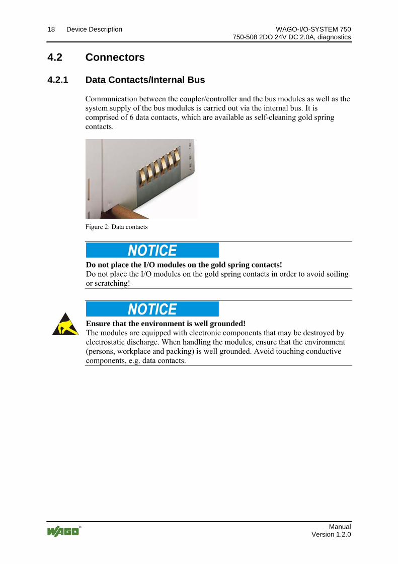
Communication between the coupler/controller and the bus modules as well as the system supply of the bus modules is carried out via the internal bus. It is comprised of 6 data contacts, which are available as self-cleaning gold spring contacts.
Figure 2: Data contacts
Po
s: 28.2 /Serie 750 (WAGO-I/O-SYSTEM)/Wichtige Erläuterungen/Sicherheitshinweise/Achtung/Achtung: Busklemmen nicht auf Goldfederkontakte legen! @ 7\mod_1266318463636_21.doc @ 50695 @ @ 1
Do not place the I/O modules on the gold spring contacts! Do not place the I/O modules on the gold spring contacts in order to avoid soiling or scratching!
s: 28.3 /Serie 750 (WAGO-I/O-SYSTEM)/Wichtige Erläuterungen/Sicherheitshinweise/Achtung/Achtung: ESD - Auf gute Erdung der Umgebung achten! @ 7\mod_1266318538667_21.doc @ 50708 @ @ 1 Po
Ensure that the environment is well grounded! The modules are equipped with electronic components that may be destroyed by electrostatic discharge. When handling the modules, ensure that the environment (persons, workplace and packing) is well grounded. Avoid touching conductive components, e.g. data contacts.
s: 29 /Dokumentation allgemein/Gliederungselemente/---Seitenwechsel--- @ 3\mod_1221108045078_0.doc @ 21810 @ @ 1 Po
Manual Version 1.2.0
WAGO-I/O-SYSTEM 750 Device Description 19 750-508 2DO 24V DC 2.0A, diagnostics
Manual Version 1.2.0
s: 30 /Serie 750 (WAGO-I/O-SYSTEM)/Gerätebeschreibung/Anschlüsse/Leistungskontakte/Feldversorgung - Überschrift 3 @ 6\mod_1256294692864_21.doc @ 43664 @ 3 @ 1 Po
4.2.2 Power Contacts/Field Supply Po
s: 31.1 /Serie 750 (WAGO-I/O-SYSTEM)/Wichtige Erläuterungen/Sicherheitshinweise/Vorsicht/Vorsicht: Verletzungsgefahr durch scharfkantige Messerkontakte! @ 6\mod_1256193279401_21.doc @ 43414 @ @ 1
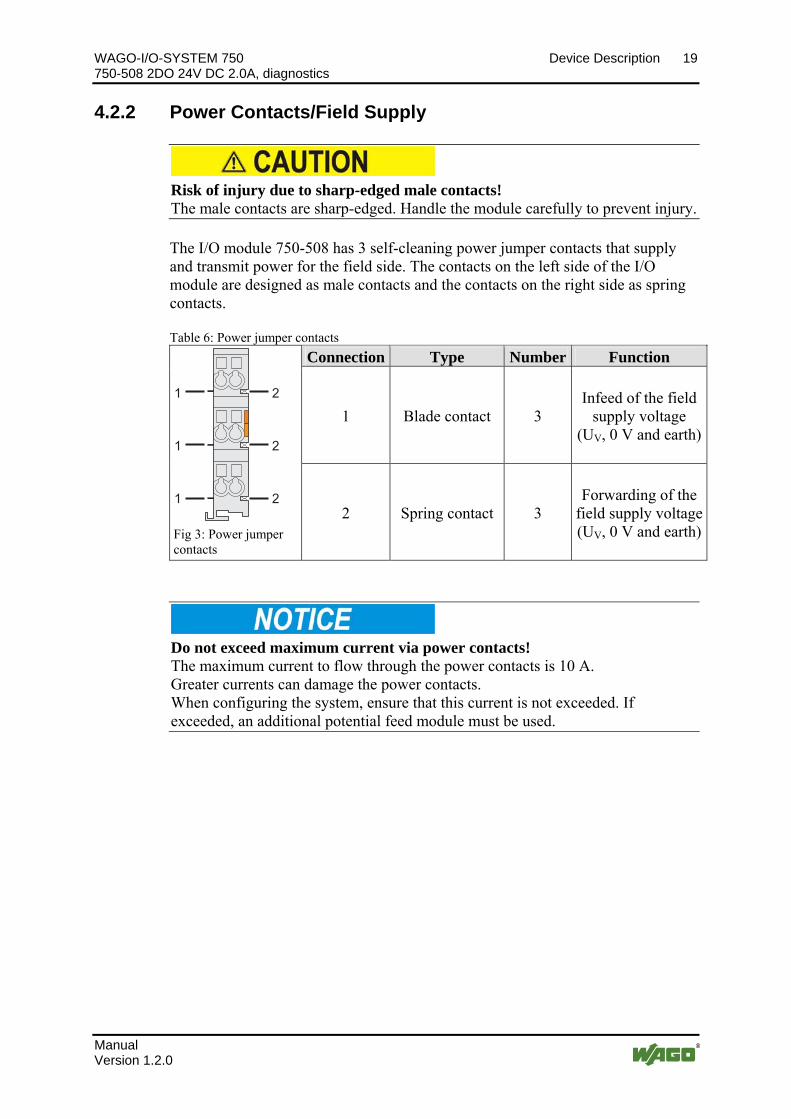
Risk of injury due to sharp-edged male contacts! The male contacts are sharp-edged. Handle the module carefully to prevent injury.
s: 31.2 /Serie 750 (WAGO-I/O-SYSTEM)/Gerätebeschreibung/Anschlüsse/Leistungskontakte 3 LK (Messer/Feder) @ 7\modPo
_1266318232808_21.doc @ 50691 @ @ 1
The I/O module 750-508 has 3 self-cleaning power jumper contacts that supply and transmit power for the field side. The contacts on the left side of the I/O module are designed as male contacts and the contacts on the right side as spring contacts.
Table 6: Power jumper contacts
Connection Type Number Function
1 Blade contact 3 Infeed of the field
supply voltage (UV, 0 V and earth)
1 2
1 2
1 2
Fig 3: Power jumper contacts
2 Spring contact 3 Forwarding of the
field supply voltage(UV, 0 V and earth)
Po
s: 31.3 /Serie 750 (WAGO-I/O-SYSTEM)/Wichtige Erläuterungen/Sicherheitshinweise/Achtung/Achtung: Maximaler Strom Leistungskontakte 10 A @ 3\mod_1226499143500_21.doc @ 25029 @ @ 1
Do not exceed maximum current via power contacts! The maximum current to flow through the power contacts is 10 A. Greater currents can damage the power contacts. When configuring the system, ensure that this current is not exceeded. If exceeded, an additional potential feed module must be used.
s: 32 /Dokumentation allgemein/Gliederungselemente/---Seitenwechsel--- @ 3\mod_1221108045078_0.doc @ 21810 @ @ 1 Po

20 Device Description WAGO-I/O-SYSTEM 750 750-508 2DO 24V DC 2.0A, diagnostics
Manual Version 1.2.0
s: 33 /Serie 750 (WAGO-I/O-SYSTEM)/Gerätebeschreibung/Anschlüsse/CAGE CLAMP-Anschlüsse - Überschrift 3 @ 6\mod_1256296337770_21.doc @ 43674 @ 3 @ 1 Po
4.2.3 CAGE CLAMP® Connections Po
s: 34 /Serie 750 (WAGO-I/O-SYSTEM)/Gerätebeschreibung/Anschlüsse/Digitalausgangsklemmen/Anschlüsse 750-0508 @ 10\mod_1298374518561_21.doc @ 69883 @ @ 1
Table 7: Connectors Connector Channel Designation Function
1 1 DO 1 Output DO 1: Signal voltage
5 2 DO 2 Output DO 2: Signal voltage
2 1 24 V Output DO 1: Field supply 24 V
6 2 24 V Output DO 2: Field supply 24 V
3 1 0 V Output DO 1: Field supply 0 V
7 2 0 V Output DO 2: Field supply 0 V
4 1 Ground Output DO 1: Ground
8 2 Ground Output DO 2: Ground
Power contacts
- +24 V Field supply 24 V
Power contacts
- 0 V Field supply 0 V
13 14
+ +
- -
750-508
0 V
24 V
0 V
DO 2
24 V
DO 1
Figure 4: Connectors
Power contacts
- Ground Field supply ground
Po
s: 35 /Dokumentation allgemein/Gliederungselemente/---Seitenwechsel--- @ 3\mod_1221108045078_0.doc @ 21810 @ @ 1

WAGO-I/O-SYSTEM 750 Device Description 21 750-508 2DO 24V DC 2.0A, diagnostics
Manual Version 1.2.0
s: 36 /Alle Serien (Allgemeine Module)/Überschriften für alle Serien/Anzeigeelemente - Überschrift 2 @ 4\mod_1240984390875_21.doc @ 31964 @ 2 @ 1 Po
4.3 Display Elements Po
s: 37 /Serie 750 (WAGO-I/O-SYSTEM)/Gerätebeschreibung/Anzeigeelemente/Digitalausgangsklemmen/Anzeigeelemente 750-0508 @ 10\mod_1298370984491_21.doc @ 69831 @ @ 1
Table 8: Display elements
LE
D
Cha
nn
el
Des
igna
tion
Nor
mal
op
erat
ion,
O
utp
ut
follo
ws
ou
tput
bit
No
load
is
con
nec
ted
*
Sh
ort
circ
uit
w
ith
GN
D*
Sh
ort
circ
uit
w
ith
24
V*
Ove
rtem
per
atu
re
at o
verl
oad
*
A Status DO 1
green off green off off off green off off off
B ErrorDO 1
off off off red red off off red red red
1 Status from
PLC to the
module
1 0 1 0 1 0 1 0 1 0
C StatusDO 2
green off green off off off green off off off
D ErrorDO 2
off off off red red off off red red red
13 14
C
D
B
A
CA
DB Figure 5: Display elements
2 Status from
PLC to the
module
1 0 1 0 1 0 1 0 1 0
Po
s: 38 /Alle Serien (Allgemeine Module)/Überschriften für alle Serien/Bedienelemente - Überschrift 2 @ 4\mod_1239191655456_21.doc @ 30439 @ 2 @ 1
4.4 Operating Elements Po
s: 39 /Serie 750 (WAGO-I/O-SYSTEM)/Gerätebeschreibung/Bedienelemente/Bedienelemente Busklemme 750-xxxx nicht vorhanden @ 4\mod_1236322031125_21.doc @ 28063 @ @ 1
The I/O module 750-508 has no operating elements. Po
s: 40 /Dokumentation allgemein/Gliederungselemente/---Seitenwechsel--- @ 3\mod_1221108045078_0.doc @ 21810 @ @ 1

22 Device Description WAGO-I/O-SYSTEM 750 750-508 2DO 24V DC 2.0A, diagnostics
s: 41 /Alle Serien (Allgemeine Module)/Überschriften für alle Serien/Schematisches Schaltbild - Überschrift 2 @ 4\mod_1240984441312_21.doc @ 31967 @ 2 @ 1 Po
4.5 Schematic Diagram Po
s: 42 /Serie 750 (WAGO-I/O-SYSTEM)/Gerätebeschreibung/Schematische Schaltbilder/Digitalausgangsklemmen/Schematisches Schaltbild 750-0508 @ 10\mod_1298371060339_21.doc @ 69843 @ @ 1
750-508
1
2
3
4
5
6
7
8
µC
DO 1
24V
0V
DO 2
DO
24 V
0 V
270 pF
10 nF 10 nF
Diag
10 nF
Status
Status
Figure 6: Schematic diagram
Po
s: 43 /Dokumentation allgemein/Gliederungselemente/---Seitenwechsel--- @ 3\mod_1221108045078_0.doc @ 21810 @ @ 1
Manual Version 1.2.0

WAGO-I/O-SYSTEM 750 Device Description 23 750-508 2DO 24V DC 2.0A, diagnostics
s: 44 /Alle Serien (Allgemeine Module)/Überschriften für alle Serien/Technische Daten - Überschrift 2 @ 3\mod_1232967587687_21.doc @ 26924 @ 2 @ 1 Po
4.6 Technical Data Po
s: 45 /Serie 750 (WAGO-I/O-SYSTEM)/Gerätebeschreibung/Technische Daten/Digitalausgangsklemmen/Technische Daten 750-0508 @ 10\mod_1298371146934_21.doc @ 69855 @ 3333 @ 1
4.6.1 Device Data
Table 9: Technical data device
Width 12 mm Height (from upper edge of 35 DIN rail) 64 mm Depth 100 mm Weight approx. 50 g
4.6.2 Power Supply
Table 10: Technical data power supply
Voltage supply Via system voltage terminal bus (5 V DC) and power jumper contacts (24 V DC)
Current consumption system voltage max.
(5 V DC) 14 mA
Current consumption power jumper contacts max. (24 V DC)
7 mA + Load
Voltage via power jumper contacts DC 24 V (-25 % ... +30 %) Current via power jumper contacts 10 A Potential isolation 500 V (System /supply)
4.6.3 Communication
Table 11: Technical data communication
Data width (internal bus) 2 byte in (status byte) 2 byte out (control byte)
Manual Version 1.2.0

24 Device Description WAGO-I/O-SYSTEM 750 750-508 2DO 24V DC 2.0A, diagnostics
4.6.4 Outputs
Table 12: Technical data outputs
Number of outputs 2 Voltage via power jumper contacts DC 24 V Output current 2,0 A Type of load resistive, inductive, lamps Reverse voltage protection yes Short-circuit limitation typ. PWM see figure below Open-circuit detection < 0,2 mA Diagnostics open circuit, overload and short circuit Restart after overload yes Switching rate max. 1 kHz Short-circuit limitation I/A
t/s5 10 15 20 25 30 35 40
5
10
15
2
Figure 7: Short-circuit limitation
Po
s: 46 /Dokumentation allgemein/Gliederungselemente/---Seitenwechsel--- @ 3\mod_1221108045078_0.doc @ 21810 @ @ 1
Manual Version 1.2.0

WAGO-I/O-SYSTEM 750 Device Description 25 750-508 2DO 24V DC 2.0A, diagnostics
s: 47 /Alle Serien (Allgemeine Module)/Überschriften für alle Serien/Zulassungen - Überschrift 2 @ 3\mod_1224055364109_21.doc @ 24030 @ 2 @ 1 Po
4.7 Approvals Po
s: 48 /Serie 750 (WAGO-I/O-SYSTEM)/Gerätebeschreibung/Zulassungen/Information: Weitere Informationen zu Zulassungen 750-xxxx @ 3\mod_1227190967156_21.doc @ 25221 @ @ 1
More Information about Approvals Detailed references to the approvals are listed in the document "Overview Approvals WAGO-I/O-SYSTEM 750", which you can find on the DVD “AUTOMATION Tools and Docs” (Item-No.: 0888-0412) or via the internet under: www.wago.com Service Documentation WAGO-I/O-SYSTEM 750 System Description.
s: 49 /Serie 750 (WAGO-I/O-SYSTEM)/Gerätebeschreibung/Zulassungen/Zulassungen Busklemme 750-xxxx Allgemein, StaPo
ndardversion und alle Varianten @ 3\mod_1233911570312_21.doc @ 27390 @ @ 1
The following approvals have been granted to the basic version and all variations of 750-508 I/O modules:
Po
s: 50.1 /Alle Serien (Allgemeine Module)/Zulassungen/Standardzulassungen/CE (Konformitätskennzeichnung) @ 3\mod_1224494777421_21.doc @ 24276 @ @ 1
Conformity Marking Po
s: 50.2 /Alle Serien (Allgemeine Module)/Zulassungen/Standardzulassungen/cULus (UL508) @ 3\mod_1224055013140_0.doc @ 24020 @ @ 1
CULUS (UL508)
s: 50.3 /Dokumentation allgemein/Gliederungselemente/------Leerzeile------ @ 3\mod_1224662755687_0.doc @ 24460 @ @Po
1
Po
s: 51 /Serie 750 (WAGO-I/O-SYSTEM)/Gerätebeschreibung/Zulassungen/Zulassungen Busklemme 750-xxxx Ex, nur Standardversion @ 9\mod_1281526321376_21.doc @ 63104 @ @ 1
The following Ex approvals have been granted to the basic version of 750-508 I/O modules:
Po
s: 52.1 /Alle Serien (Allgemeine Module)/Zulassungen/Ex Zulassungen/TÜV (07 ATEX 554086 X) I M2 Ex d I II 3 G Ex nA IIC T4 II 3 D Ex tD A22 IP6X T135°C @ 9\mod_1291718131887_0.doc @ 67162 @ @ 1
TÜV 07 ATEX 554086 X
I M2 Ex d I II 3 G Ex nA IIC T4 II 3 D Ex tD A22 IP6X T135°C
s: 52.2 /Alle Serien (Allgemeine Module)/Zulassungen/Ex Zulassungen/Ergänzung Betriebstemperatur 0 °C <= TA <= +60 °C @ 9\mod_1295605895541_21.doc @ 68610 @ @ 1 Po
Permissible operation temperature: 0 °C ≤ TA ≤ +60 °C
s: 52.3 /Alle Serien (Allgemeine Module)/Zulassungen/Ex Zulassungen/TÜV (TUN 09.001X) Ex d I Ex nA IIC T4 Ex tD A22 IP6X T135°C @ 9\mod_1291718893505_0.doc @ 67166 @ @ 1 Po
TÜV TUN 09.0001X
Ex d I Ex nA IIC T4 Ex tD A22 IP6X T135°C
s: 52.4 /Alle Serien (Allgemeine Module)/Zulassungen/Ex Zulassungen/Ergänzung Betriebstemperatur 0 °C <= TA <= +60 °C @ 9\mod_1295605895541_21.doc @ 68610 @ @ 1 Po
Permissible operation temperature: 0 °C ≤ TA ≤ +60 °C
s: 52.5 /Alle Serien (Allgemeine Module)/Zulassungen/Ex Zulassungen/cULus (ANSI/ISA 12.12.01) Class I, Div2 ABCD T4 @ 3\mod_1224054791812_0.doc @ 24014 @ @ 1 Po
CULUS ANSI/ISA 12.12.01 Class I, Div2 ABCD T4
Po
s: 52.6 /Dokumentation allgemein/Gliederungselemente/------Leerzeile------ @ 3\mod_1224662755687_0.doc @ 24460 @ @ 1
Po
s: 53 /Serie 750 (WAGO-I/O-SYSTEM)/Gerätebeschreibung/Zulassungen/Zulassungen Busklemme 750-xxxx Ex, nur Variante /000-800 @ 10\mod_1302613660663_21.doc @ 71866 @ @ 1
The following Ex approvals have been granted to the variation 750-508/000-800: Po
s: 54 /Alle Serien (Allgemeine Module)/Zulassungen/Ex Zulassungen/cULus (ANSI/ISA 12.12.01) Class I, Div2 ABCD T4 @ 3\mod_1224054791812_0.doc @ 24014 @ @ 1
CULUS ANSI/ISA 12.12.01 Class I, Div2 ABCD T4
Po
s: 55 /Alle Serien (Allgemeine Module)/Zulassungen/Ex Zulassungen/DEMKO (08 ATEX 142851 X) I M2/II 3 G/D Ex nA IIC T4 @ 5\mod_1245298914171_0.doc @ 35520 @ @ 1
DEMKO 08 ATEX 142851 X I M2/II 3 G/D Ex nA IIC T4
Pos: 56 /
Dokumentation allgemein/Gliederungselemente/------Leerzeile------ @ 3\mod_1224662755687_0.doc @ 24460 @ @ 1
Po
s: 57 /Serie 750 (WAGO-I/O-SYSTEM)/Gerätebeschreibung/Zulassungen/Zulassungen Busklemme 750-xxxx Schiff, nur Standardversion @ 9\mod_1281526425939_21.doc @ 63108 @ @ 1
The following ship approvals have been granted to the basic version of 750-508 I/O modules:
Po
s: 58 /Alle Serien (Allgemeine Module)/Zulassungen/Schiffszulassungen/BSH (Bundesamt für Seeschifffahrt und Hydrographie) @ 5\mod_1246341825156_21.doc @ 36334 @ @ 1
Manual Version 1.2.0

26 Device Description WAGO-I/O-SYSTEM 750 750-508 2DO 24V DC 2.0A, diagnostics
Federal Maritime and Hydrographic Agency
s: 59 /Alle Serien (Allgemeine Module)/Zulassungen/Schiffszulassungen/DNV (Det Norske Veritas) Class B @ 3\mod_1224492540562_0.doc @ 24224 @ @ 1 Po
DNV (Det Norske Veritas) Class B
Pos: 60 /Alle Serien (Allgemeine Module)/Zulassungen/Schiffszulassungen/GL (Germanischer Lloyd) Cat. A, B, C, D (EMC 1) @ 3\mod_1224492724484_0.doc @ 24228 @ @ 1
GL (Germanischer Lloyd) Cat. A, B, C, D (EMC 1)
Pos: 61 /Alle Serien (Allgemeine Module)/Zulassungen/Schiffszulassungen/LR (Lloyd’s Register) Env. 1, 2, 3, 4 @ 3\mod_1224492890453_0.doc @ 24236 @ @ 1
LR (Lloyd’s Register) Env. 1, 2, 3, 4 Pos: 62 /Alle Serien (Allgemeine Module)/Zulassungen/Schiffszulassungen/PRS (Polski Rejestr Statków) @ 3\mod_1224497273250_0.doc @ 24295 @ @ 1
PRS (Polski Rejestr Statków)
Po
s: 63 /Alle Serien (Allgemeine Module)/Zulassungen/Schiffszulassungen/RINA (Registro Italiano Navale) @ 3\mod_1224493078359_0.doc @ 24244 @ @ 1
RINA (Registro Italiano Navale)
Po
s: 64 /Dokumentation allgemein/Gliederungselemente/------Leerzeile------ @ 3\mod_1224662755687_0.doc @ 24460 @ @ 1
Pos: 65 /Alle Serien (Allgemeine Module)/Überschriften für alle Serien/Normen und Richtlinien - Überschrift 2 @ 4\mod_1242804031875_21.doc @ 33646 @ 2 @ 1
4.8 Standards and Guidelines Po
s: 66 /Serie 750 (WAGO-I/O-SYSTEM)/Gerätebeschreibung/Normen und Richtlinien/EMV-Normen Busklemme 750-xxxx, ohne Variantenangabe @ 4\mod_1242803944015_21.doc @ 33642 @ @ 1
750-508 I/O modules meet the following requirements on emission and immunity of interference:
Po
s: 67 /Alle Serien (Allgemeine Module)/Normen und Richtlinien/EMV CE-Störaussendung EN 61000-6-4: 2007 @ 4\mod_1242798273984_21.doc @ 33602 @ @ 1
EMC CE-Immunity to interference acc. to EN 61000-6-4: 2007 Pos: 68 /Alle Serien (Allgemeine Module)/Normen und Richtlinien/EMV CE-Störfestigkeit EN 61000-6-2: 2005 @ 4\mod_1242797655625_21.doc @ 33591 @ @ 1
EMC CE-Immunity to interference acc. to EN 61000-6-2: 2005 Pos: 69 /Alle Serien (Allgemeine Module)/Normen und Richtlinien/EMV Schiffbau-Störaussendung Germanischer Lloyd (2003) @ 4\mod_1242798400546_21.doc @ 33606 @ @ 1
EMC marine applications-Emission of interference acc. to Germanischer Lloyd (2003)
Pos: 70 /Alle Serien (Allgemeine Module)/Normen und Richtlinien/EMV Schiffbau-Störfestigkeit Germanischer Lloyd (2003) @ 4\mod_1242798409640_21.doc @ 33610 @ @ 1
EMC marine applications-Immunity to interference acc. to Germanischer Lloyd (2003)
Pos: 71 /Dokumentation allgemein/Gliederungselemente/---Seitenwechsel--- @ 3\mod_1221108045078_0.doc @ 21810 @ @ 1
Manual Version 1.2.0

WAGO-I/O-SYSTEM 750 Assembly 27 750-508 2DO 24V DC 2.0A, diagnostics
s: 72 /Alle Serien (Allgemeine Module)/Überschriften für alle Serien/Montieren - Überschrift 1 @ 3\mod_1225446744750_21.doc @ 24900 @ 1 @ 1 Po
5 Assembly Po
s: 73.1 /Serie 750 (WAGO-I/O-SYSTEM)/Montieren/Montagereihenfolge @ 3\mod_1231770210031_21.doc @ 25992 @ 2 @ 1
5.1 Assembly Sequence
All system components can be snapped directly on a carrier rail in accordance with the European standard EN 50022 (DIN 35).
The reliable positioning and connection is made using a tongue and groove system. Due to the automatic locking, the individual components are securely seated on the rail after installation.
Starting with the coupler/controller, the bus modules are assembled adjacent to each other according to the project design. Errors in the design of the node in terms of the potential groups (connection via the power contacts) are recognized, as the bus modules with power contacts (male contacts) cannot be linked to bus modules with fewer power contacts.
Po
s: 73.2 /Serie 750 (WAGO-I/O-SYSTEM)/Wichtige Erläuterungen/Sicherheitshinweise/Vorsicht/Vorsicht: Verletzungsgefahr durch scharfkantige Messerkontakte! @ 6\mod_1256193279401_21.doc @ 43414 @ @ 1
Risk of injury due to sharp-edged male contacts! The male contacts are sharp-edged. Handle the module carefully to prevent injury.
s: 73.3 /Serie 750 (WAGO-I/O-SYSTEM)/Wichtige Erläuterungen/Sicherheitshinweise/Achtung/Achtung: Busklemmen in vorgegebener Reihenfolge stecken! @ 6\mod_1256194177073_21.doc @ 43429 @ @ 1 Po
Connect the I/O modules in the required order! Never plug bus modules from the direction of the end terminal. A ground wire power contact, which is inserted into a terminal without contacts, e.g. a 4-channel digital input module, has a decreased air and creepage distance to the neighboring contact in the example DI4.
s: 73.4 /Serie 750 (WAGO-I/O-SYSTEM)/Wichtige Erläuterungen/Sicherheitshinweise/Achtung/Achtung: Aneinanderreihen von Busklemmen nur bei offener Nut! @ 6\mod_1256193351448_21.doc @ 43417 @ @ 1 Po
Assemble the I/O modules in rows only if the grooves are open! Please take into consideration that some bus modules have no or only a few power jumper contacts. The design of some modules does not allow them to be physically assembled in rows, as the grooves for the male contacts are closed at the top.
s: 73.5 /Serie 750 (WAGO-I/O-SYSTEM)/Wichtige Erläuterungen/Sicherheitshinweise/Hinweis/Hinweis: Busabschluss nicht vergessen! @ 6\mod_1256194225557_21.doc @ 43432 @ @ 1 Po
Don't forget the bus end module! Always plug a bus end module 750-600 onto the end of the fieldbus node! You must always use a bus end module at all fieldbus nodes with the WAGO I/O System 750 fieldbus couplers/controllers to guarantee proper data transfer.
6 /Dokumentation allgemein/Gliederungselemente/---Seitenwechsel--- @ 3\mod_1221108045078_0.doc @ 21810 @ @ 1 Pos: 73.
Manual Version 1.2.0
28 Assembly WAGO-I/O-SYSTEM 750 750-508 2DO 24V DC 2.0A, diagnostics
s: 73.7 /Serie 750 (WAGO-I/O-SYSTEM)/Montieren/Geräte einfügen und entfernen - Überschrift 2 @ 3\mod_1231768483250_21.doc @ 25950 @ 2 @ 1 Po
5.2 Inserting and Removing Devices Po
s: 73.8 /Serie 750 (WAGO-I/O-SYSTEM)/Wichtige Erläuterungen/Sicherheitshinweise/Gefahr/Gefahr: Vorsicht bei der Unterbrechung von FE! @ 6\mod_1256193919214_21.doc @ 43423 @ @ 1
Use caution when interrupting the PE! Make sure that people or equipment are not placed at risk when removing an I/O module and the associated PE interruption. To prevent interruptions, provide ring feeding of the ground conductor, see section "Grounding/Ground Conductor" in manual "System Description WAGO-I/O-SYSTEM 750".
s: 73.9 /Alle Serien (Allgemeine Module)/Wichtige Erläuterungen/Sicherheitshinweise/Achtung/Achtung: Arbeiten an Geräten nur spannungsfrei durchführen! @ 6\mod_1256193963573_21.doc @ 43426 @ @ 1 Po
Perform work on devices only if the system is de-energized! Working on devices when the system is energized can damage the devices. Therefore, turn off the power supply before working on the devices.
s: 73.10 /Serie 750 (WAGO-I/O-SYSTEM)/Montieren/Busklemme einfügen @ 3\mod_1231769726703_21.doc @ 25989 @ 3 @ 1 Po
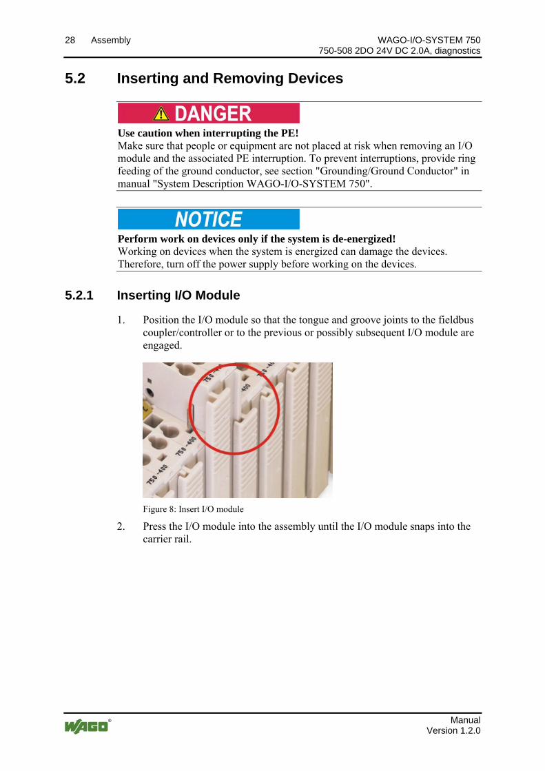
5.2.1 Inserting I/O Module
1. Position the I/O module so that the tongue and groove joints to the fieldbus coupler/controller or to the previous or possibly subsequent I/O module are engaged.
Figure 8: Insert I/O module
2. Press the I/O module into the assembly until the I/O module snaps into the carrier rail.
Manual Version 1.2.0

WAGO-I/O-SYSTEM 750 Assembly 29 750-508 2DO 24V DC 2.0A, diagnostics
Figure 9: Snap the I/O module into place
With the I/O module snapped in place, the electrical connections for the data contacts and power contacts (if any) to the fieldbus coupler/controller or to the previous or possibly subsequent I/O module are established.
Po
s: 73.11 /Serie 750 (WAGO-I/O-SYSTEM)/Montieren/Busklemme entfernen @ 4\mod_1239169375203_21.doc @ 30334 @ 3 @ 1
5.2.2 Removing the I/O Module
1. Remove the I/O module from the assembly by pulling the release tab.
Figure 10: Removing the I/O module
Electrical connections for data or power contacts are disconnected when removing the I/O module.
Po
s: 74 /Dokumentation allgemein/Gliederungselemente/---Seitenwechsel--- @ 3\mod_1221108045078_0.doc @ 21810 @ @ 1
Manual Version 1.2.0

30 Connect Devices WAGO-I/O-SYSTEM 750 750-508 2DO 24V DC 2.0A, diagnostics
s: 75 /Alle Serien (Allgemeine Module)/Überschriften für alle Serien/Geräte anschließen - Überschrift 1 @ 3\mod_1234172889468_21.doc @ 27460 @ 1 @ 1 Po
6 Connect Devices Po
s: 76 /Serie 750 (WAGO-I/O-SYSTEM)/Anschließen/Leiter an CAGE CLAMP anschließen - Überschrift 2 und Text @ 3\mod_1225448660171_21.doc @ 24928 @ 2 @ 1
6.1 Connecting a conductor to the CAGE CLAMP®
The WAGO CAGE CLAMP® connection is appropriate for solid, stranded and finely stranded conductors.
Only connect one conductor to each CAGE CLAMP® connection! Only one conductor may be connected to each CAGE CLAMP® connection. Do not connect more than one conductor at one single connection!
If more than one conductor must be routed to one connection, these must be connected in an up-circuit wiring assembly, for example using WAGO feed-through terminals.
Exception: If it is unavoidable to jointly connect 2 conductors, then you must use a ferrule to join the wires together. The following ferrules can be used: Length 8 mm Nominal cross section max. 1 mm2 for 2 conductors with 0.5 mm2 each WAGO Product 216-103 or products with comparable properties. 1. To open the CAGE CLAMP® insert the actuating tool into the opening
above the connection.
2. Insert the conductor into the corresponding connection opening.
3. To close the CAGE CLAMP® simply remove the tool - the conductor is then clamped firmly in place.
Figure 11: Connecting a conductor to a CAGE CLAMP®
Po
s: 77 /Dokumentation allgemein/Gliederungselemente/---Seitenwechsel--- @ 3\mod_1221108045078_0.doc @ 21810 @ @ 1
Manual Version 1.2.0

WAGO-I/O-SYSTEM 750 Connect Devices 31 750-508 2DO 24V DC 2.0A, diagnostics
s: 78 /Alle Serien (Allgemeine Module)/Überschriften für alle Serien/Anschlussbeispiele - Überschrift 2 @ 4\mod_1240996036328_21.doc @ 32010 @ 2 @ 1 Po
6.2 Connection Examples Po
s: 79 /Serie 750 (WAGO-I/O-SYSTEM)/Anschließen/Anschlussbeispiele/Digitalausgangsklemmen/Anschlussbeispiele 750-0508 @ 10\mod_1298558628361_21.doc @ 70209 @ 3333 @ 1
6.2.1 2-Conductor Connection, ungrounded
13 14
+ +
- -
750-508
Figure 12: Connecting diagram 2-conductor connection, ungrounded
6.2.2 2-Conductor Connection, grounded
13 14
+ +
- -
750-508
Figure 13: Connecting diagram 2-conductor connection, grounded
Manual Version 1.2.0

32 Connect Devices WAGO-I/O-SYSTEM 750 750-508 2DO 24V DC 2.0A, diagnostics
6.2.3 3-Conductor Connection, ungrounded
13 14
+ +
- -
750-508
- ++-
Figure 14: Connecting diagram 3-conductor connection, ungrounded
6.2.4 3-Conductor Connection, grounded
13 14
+ +
- -
750-508
-- + +
Figure 15: Connecting diagram 3-conductor connection, grounded
Po
s: 80 /Dokumentation allgemein/Gliederungselemente/---Seitenwechsel--- @ 3\mod_1221108045078_0.doc @ 21810 @ @ 1
Manual Version 1.2.0

WAGO-I/O-SYSTEM 750 Process Image 33 750-508 2DO 24V DC 2.0A, diagnostics
s: 81 /Alle Serien (Allgemeine Module)/Überschriften für alle Serien/Prozessabbild - Überschrift 1 @ 4\mod_1240983067828_21.doc @ 31942 @ 1 @ 1 Po
7 Process Image Po
s: 82 /Serie 750 (WAGO-I/O-SYSTEM)/Prozessabbild Klemmenbus/Hinweis: Prozessabbildmapping ohne Status-/Controlbyte @ 6\mod_1256126797251_21.doc @ 43340 @ @ 1
Mapping of process data in the process image of fieldbus systems The representation of the process data of some I/O modules or their variations in the process image depends on the fieldbus coupler/controller used. Please take this information from the section "Fieldbus Specific Design of the Process Data" included in the description concerning the process image of the corresponding coupler/controller.
Po
s: 83 /Serie 750 (WAGO-I/O-SYSTEM)/Prozessabbild Klemmenbus/Digitalausgangsklemmen/Prozessabbild 750-05xx 2 DO/DIAG @ 10\mod_1299506283577_21.doc @ 70540 @ @ 1
Table 13: Output Byte D0 Bit 7 Bit 6 Bit 5 Bit 4 Bit 3 Bit 2 Bit 1 Bit 0
0 0 0 0 0 0 DO 2 DO 1 DO 1 Signal state DO 1 – Digital Output Channel 1 DO 2 Signal state DO 2 – Digital Output Channel 2 0 Reserved Table 14: Input Byte D0
Bit 7 Bit 6 Bit 5 Bit 4 Bit 3 Bit 2 Bit 1 Bit 0 0 0 0 0 0 0 DIAG 2 DIAG 1
0: Normal operation, output DO 1 follows the output bit. DIAG 1 1: Error at output DO 1:
a) No load connected or b) Short circuit with GND or c) Short circuit with 24 V or d) Overtemperature at overload
0: Normal operation, output DO 2 follows the output bit. DIAG 2 1: Error at output DO 2:
a) No load connected or b) Short circuit with GND or c) Short circuit with 24 V or d) Overtemperature at overload
0 Reserved
Po
s: 84 /Dokumentation allgemein/Gliederungselemente/---Seitenwechsel--- @ 3\mod_1221108045078_0.doc @ 21810 @ @ 1
Manual Version 1.2.0

34 Using Interference-Free Variations of I/O Modules in Safety Related ApplicationsWAGO-I/O-SYSTEM 750 750-508 2DO 24V DC 2.0A, diagnostics
s: 85.1 /Serie 750 (WAGO-I/O-SYSTEM)/Einsatz in sicherheitsgerichteten Anwendungen/Einleitung - rückwirkungsfreie Varianten @ 6\mod_1258973563064_21.doc @ 44681 @ 1 @ 1 Po
8 Using Interference-Free Variations of I/O Modules in Safety Related Applications
The variation 750-508/xxx-8xx of the I/O module 750-508 (designation “... /R“ in the product name) is suited for use in interference-free safety circuits.
Po
s: 85.2 /Serie 750 (WAGO-I/O-SYSTEM)/Einsatz in sicherheitsgerichteten Anwendungen/Sicherheitsverhalten @ 6\mod_1258973946909_21.doc @ 44685 @ @ 1
If the field side supply is shut down via a safety switching device, the safety function of the module is not active. When the interference-free IO module is used correctly in a safety related application, neither the SIL or Performance Level achieved by the circuit nor the Category will be influenced. This requires that you adhere to the following notes and connection diagrams!
Po
s: 85.3 /Dokumentation allgemein/Gliederungselemente/---Seitenwechsel--- @ 3\mod_1221108045078_0.doc @ 21810 @ @ 1
Manual Version 1.2.0

WAGO-I/O-SYSTEM 750 Using Interference-Free Variations of I/O Modules in Safety Related Applications 35 750-508 2DO 24V DC 2.0A, diagnostics
Po wendungen/Hinweise zum Einsatz in Sicherheitsanwendungen @ 6\mod_12589748111 Einsatz der rückwirkungsfreien Digitalausgangsklemme in Sicherheitsanwendungen
s: 85.4 /Serie 750 (WAGO-I/O-SYSTEM)/Einsatz in sicherheitsgerichteten An 438_21.doc @ 44688 @ 2 @ 1
8.1 Important Notes
Damage to Property! Only a power supply unit with protective extra-low voltage (PELV) shall be used for the 24 V power supply.
Damage to Property! IP54 protection class is absolutely mandatory. This means that the interference-free digital output module shall only be integrated and operated in switch boxes or switch cabinets complying with IP54 or higher.
Damage to Property! The 24 V power supply shall never be applied to the output of an interference-free digital output module. This wiring failure will not be detected by the system.
Damage to Property! A group of interference-free digital output modules shall only be supplied using a safety switching device. Reverse supply must absolutely be avoided.
Damage to Property! Short circuits between outputs of different interference-free digital output modules must absolutely be avoided as they are not detected by the system.
According to EN ISO 13849-2, the following measures are required for an "external voltage" fault exclusion:
- Use of cables routed separately and - Protection from external damage (e.g., caused by cable duct).
Pos: 85.
5 /Dokumentation allgemein/Gliederungselemente/---Seitenwechsel--- @ 3\mod_1221108045078_0.doc @ 21810 @ 2 @ 1
Manual Version 1.2.0
36 Using Interference-Free Variations of I/O Modules in Safety Related ApplicationsWAGO-I/O-SYSTEM 750 750-508 2DO 24V DC 2.0A, diagnostics
s: 85.6 /Serie 750 (WAGO-I/O-SYSTEM)/Einsatz in sicherheitsgerichteten Anwendungen/Allgemeiner Aufbau einer Potentialgruppe - rückwirkungsfreie Varianten @ 6\mod_1258973074755_21.doc @ 44664 @ 23 @ 1 Po
8.2 Connecting the IO Module to Safety Switching Devices or Safety Modules
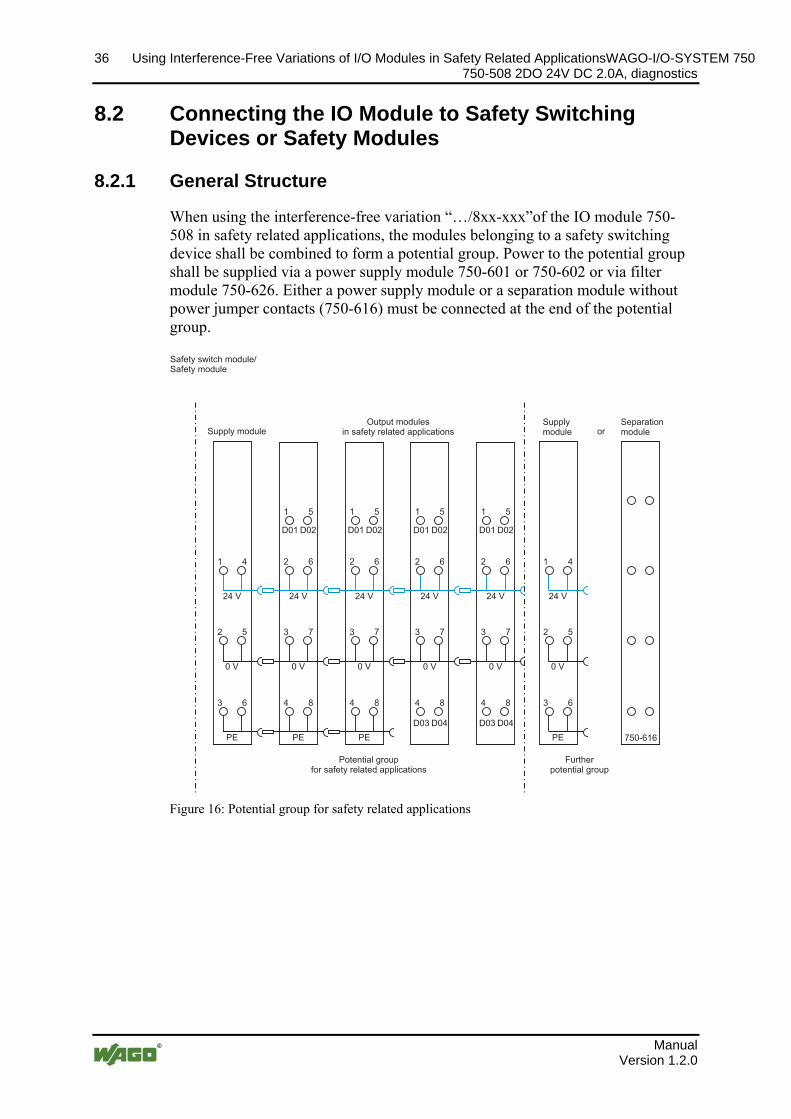
8.2.1 General Structure
When using the interference-free variation “…/8xx-xxx”of the IO module 750-508 in safety related applications, the modules belonging to a safety switching device shall be combined to form a potential group. Power to the potential group shall be supplied via a power supply module 750-601 or 750-602 or via filter module 750-626. Either a power supply module or a separation module without power jumper contacts (750-616) must be connected at the end of the potential group.
Po
s: 85.7 /Serie 750 (WAGO-I/O-SYSTEM)/Einsatz in sicherheitsgerichteten Anwendungen/Aufbau einer Potentialgruppe @ 6\mod_1259221280455_21.doc @ 45332 @ @ 1
1 4
2 5
3 6
24 V
0 V
PE
4 8
3 7
2 6
1 5
D01 D02
24 V
0 V
PE
4 8
3 7
2 6
1 5
D01 D02
24 V
0 V
PE
1 4
2 5
3 6
24 V
0 V
PE 750-616
4 8
3 7
2 6
1 5
D01 D02
24 V
0 V
D03 D04
4 8
3 7
2 6
1 5
D01 D02
24 V
0 V
D03 D04
Safety switch module/Safety module
Supply moduleOutput modules
in safety related applicationsSupplymodule or
Separationmodule
Potential groupfor safety related applications
Furtherpotential group
Figure 16: Potential group for safety related applications
Po
s: 86 /Dokumentation allgemein/Gliederungselemente/---Seitenwechsel--- @ 3\mod_1221108045078_0.doc @ 21810 @ @ 1
Manual Version 1.2.0
WAGO-I/O-SYSTEM 750 Using Interference-Free Variations of I/O Modules in Safety Related Applications 37 750-508 2DO 24V DC 2.0A, diagnostics
Po endungen/Anschlussbeispiele/Anschlussbeispiel 2/4-Kanal-Digitalausgangsklemmen i1 Einsatz der rückwirkungsfreien Digitalausgangsklemme in Sicherheitsanwendungen
s: 87 /Serie 750 (WAGO-I/O-SYSTEM)/Einsatz in sicherheitsgerichteten Anw n Sicherheitsanwendungen @ 6\mod_1259219930757_21.doc @ 45290 @ 3 @ 1
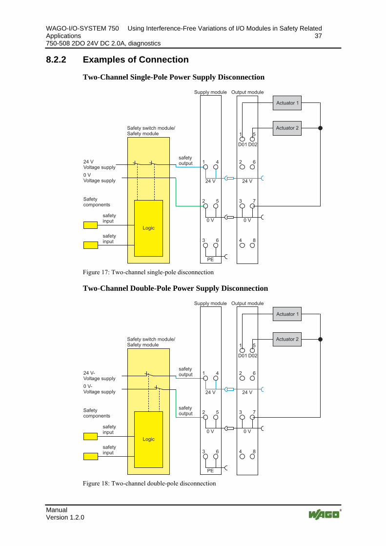
8.2.2 Examples of Connection
Two-Channel Single-Pole Power Supply Disconnection
1 4
2 5
3 6 4 8
3 7
2 6
1 5
D01 D02
24 V 24 V
0 V 0 V
PE
24 VVoltage supply
Safetycomponents
safetyinput
safetyinput
Safety switch module/Safety module
safetyoutput
Logic
Supply module Output module
Actuator 1
Actuator 2
0 VVoltage supply
Figure 17: Two-channel single-pole disconnection
Two-Channel Double-Pole Power Supply Disconnection
1 4
2 5
3 6 4 8
3 7
2 6
1 5
D01 D02
24 V 24 V
0 V 0 V
PE
24 V-Voltage supply
Safetycomponents
safetyinput
safetyinput
Safety switch module/Safety module
safetyoutput
Logic
Supply module Output module
Actuator 1
Actuator 2
safetyoutput
0 V-Voltage supply
Figure 18: Two-channel double-pole disconnection
Manual Version 1.2.0

38 Using Interference-Free Variations of I/O Modules in Safety Related ApplicationsWAGO-I/O-SYSTEM 750 750-508 2DO 24V DC 2.0A, diagnostics
Po
s: 88 /Dokumentation allgemein/Gliederungselemente/---Seitenwechsel--- @ 3\mod_1221108045078_0.doc @ 21810 @ @ 1
Manual Version 1.2.0

WAGO-I/O-SYSTEM 750 Use in Hazardous Environments 39 750-508 2DO 24V DC 2.0A, diagnostics
s: 89.1 /Alle Serien (Allgemeine Module)/Einsatz in Ex-Bereichen/Einsatz in explosionsgefährdeten Bereichen - Überschrift 1 @ 3\mod_1224075191281_21.doc @ 24084 @ 1 @ 1 Po
9 Use in Hazardous Environments Po
s: 89.2 /Serie 750 (WAGO-I/O-SYSTEM)/Einsatz in Ex-Bereichen/Einsatzbereich Serie 750 @ 3\mod_1234272230203_21.doc @ 27500 @ @ 1
The WAGO-I/O-SYSTEM 750 (electrical equipment) is designed for use in Zone 2 hazardous areas.
The following sections include both the general identification of components (devices) and the installation regulations to be observed. The individual subsections of the "Installation Regulations" section must be taken into account if the I/O module has the required approval or is subject to the range of application of the ATEX directive.
Po
s: 89.3 /Dokumentation allgemein/Gliederungselemente/---Seitenwechsel--- @ 3\mod_1221108045078_0.doc @ 21810 @ @ 1
Manual Version 1.2.0

40 Use in Hazardous Environments WAGO-I/O-SYSTEM 750 750-508 2DO 24V DC 2.0A, diagnostics
s: 89.4 /Serie 750 (WAGO-I/O-SYSTEM)/Einsatz in Ex-Bereichen/Kennzeichnung - Überschrift 2 @ 3\mod_1224157499140_21.doc @ 24182 @ 2 @ 1 Po
9.1 Identification Po
s: 89.5 /Serie 750 (WAGO-I/O-SYSTEM)/Einsatz in Ex-Bereichen/Kennzeichnung für Europa gemäß CENELEC und IEC - Überschrift 3 @ 3\mod_1224157620203_21.doc @ 24185 @ 3 @ 1
9.1.1 For Europe according to CENELEC and IEC Po
s: 89.6 /Serie 750 (WAGO-I/O-SYSTEM)/Einsatz in Ex-Bereichen/Bedruckung gemäß CENELEC und IEC @ 7\mod_1274340031573_21.doc @ 56687 @ @ 1
Figure 19: Example for lateral labeling of bus modules
Figure 20: Printing on text detail in accordance with CENELEC and IEC
Table 15: Description of Printing on
Printing on Text Description DEMKO 08 ATEX 142851 X IECEx PTB 07.0064X
Approval body and/or number of the examination certificate
I M2 / II 3 GD Explosion protection group and Unit category Ex nA Type of ignition and extended identification IIC Explosion protection group T4 Temperature class
Po
s: 89.7 /Dokumentation allgemein/Gliederungselemente/---Seitenwechsel--- @ 3\mod_1221108045078_0.doc @ 21810 @ @ 1
Manual Version 1.2.0
WAGO-I/O-SYSTEM 750 Use in Hazardous Environments 41 750-508 2DO 24V DC 2.0A, diagnostics
s: 89.8 /Serie 750 (WAGO-I/O-SYSTEM)/Einsatz in Ex-Bereichen/Bedruckung gemäß Ex i und IEC Ex i @ 7\mod_1274338578856_21.doc @ 56679 @ @ 1 Po
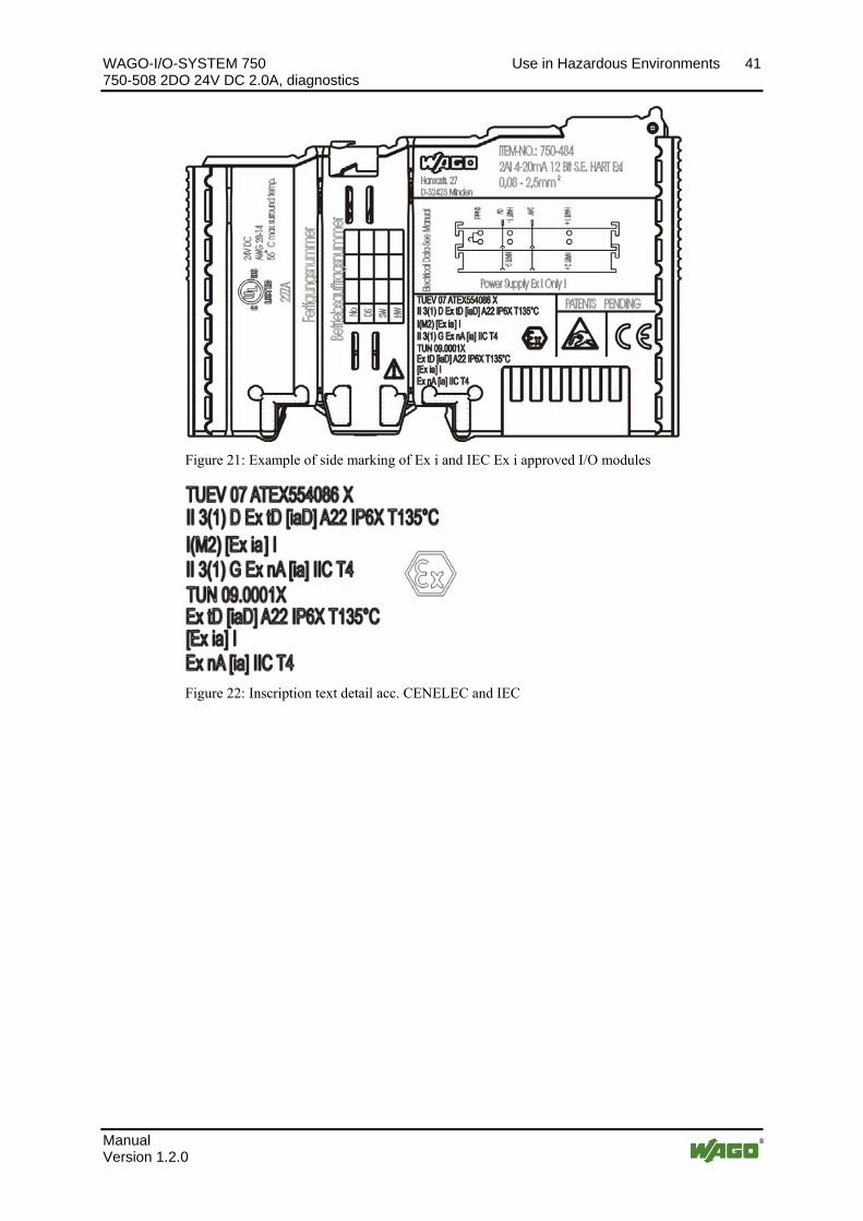
Figure 21: Example of side marking of Ex i and IEC Ex i approved I/O modules
Figure 22: Inscription text detail acc. CENELEC and IEC
Manual Version 1.2.0
42 Use in Hazardous Environments WAGO-I/O-SYSTEM 750 750-508 2DO 24V DC 2.0A, diagnostics
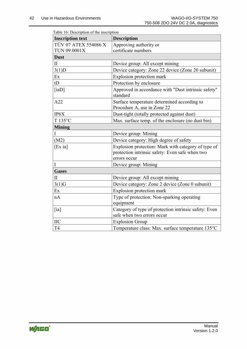
Table 16: Description of the inscription
Inscription text Description TÜV 07 ATEX 554086 X TUN 09.0001X
Approving authority or certificate numbers
Dust II Device group: All except mining 3(1)D Device category: Zone 22 device (Zone 20 subunit) Ex Explosion protection mark tD Protection by enclosure [iaD] Approved in accordance with "Dust intrinsic safety"
standard A22 Surface temperature determined according to
Procedure A, use in Zone 22 IP6X Dust-tight (totally protected against dust) T 135°C Max. surface temp. of the enclosure (no dust bin) Mining I Device group: Mining (M2) Device category: High degree of safety [Ex ia] Explosion protection: Mark with category of type of
protection intrinsic safety: Even safe when two errors occur
I Device group: Mining Gases II Device group: All except mining 3(1)G Device category: Zone 2 device (Zone 0 subunit) Ex Explosion protection mark nA Type of protection: Non-sparking operating
equipment [ia] Category of type of protection intrinsic safety: Even
safe when two errors occur IIC Explosion Group T4 Temperature class: Max. surface temperature 135°C
Po
s: 89.9 /Dokumentation allgemein/Gliederungselemente/---Seitenwechsel--- @ 3\mod_1221108045078_0.doc @ 21810 @ @ 1
Manual Version 1.2.0
WAGO-I/O-SYSTEM 750 Use in Hazardous Environments 43 750-508 2DO 24V DC 2.0A, diagnostics
s: 89.10 /Serie 750 (WAGO-I/O-SYSTEM)/Einsatz in Ex-Bereichen/Kennzeichnung für Amerika gemäß NEC - Überschrift 3 @ 3\mod_1224158423187_21.doc @ 24188 @ 3 @ 1 Po
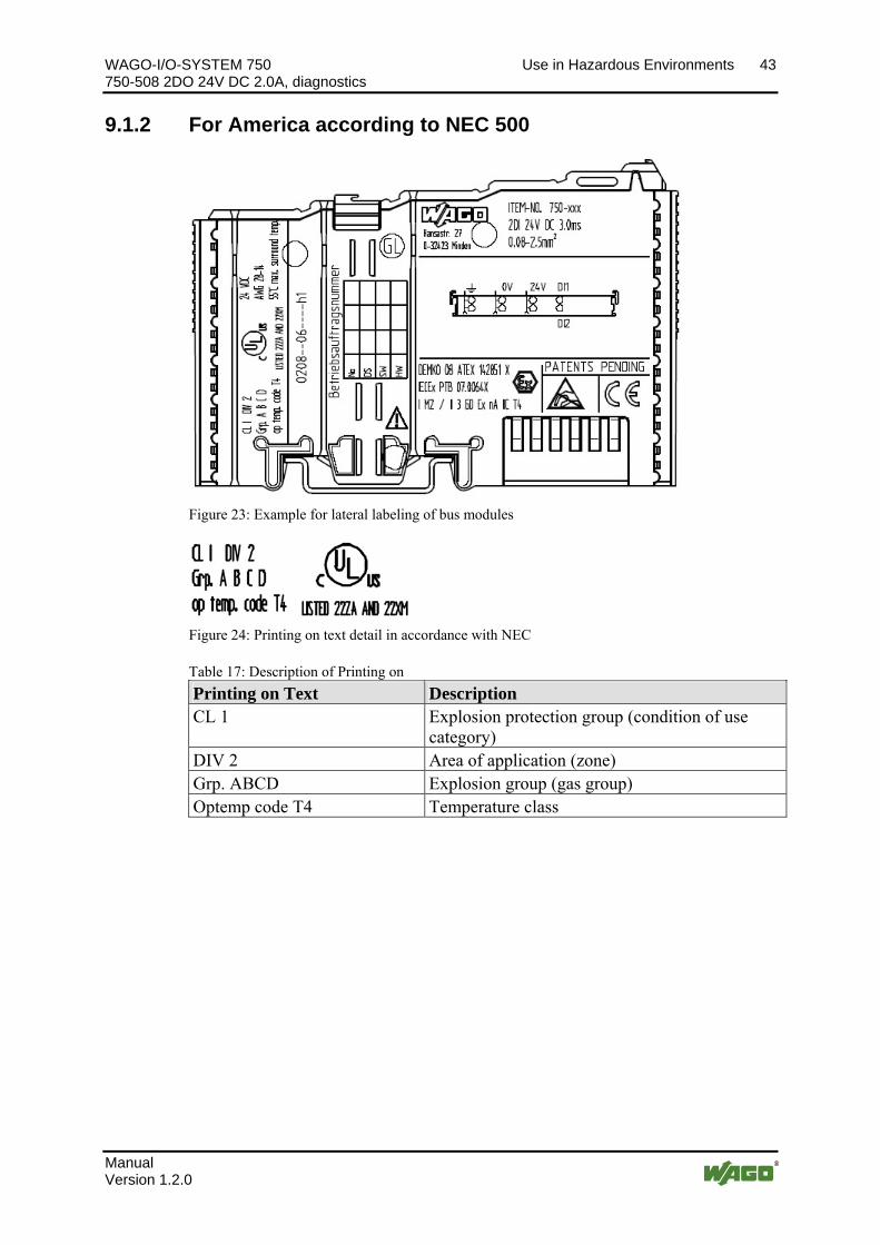
9.1.2 For America according to NEC 500 Po
s: 89.11 /Serie 750 (WAGO-I/O-SYSTEM)/Einsatz in Ex-Bereichen/Bedruckung gemäß NEC @ 7\mod_1274339607920_21.doc @ 56683 @ @ 1
Figure 23: Example for lateral labeling of bus modules
Figure 24: Printing on text detail in accordance with NEC
Table 17: Description of Printing on
Printing on Text Description CL 1 Explosion protection group (condition of use
category) DIV 2 Area of application (zone) Grp. ABCD Explosion group (gas group) Optemp code T4 Temperature class
Po
s: 89.12 /Dokumentation allgemein/Gliederungselemente/---Seitenwechsel--- @ 3\mod_1221108045078_0.doc @ 21810 @ @ 1
Manual Version 1.2.0

44 Use in Hazardous Environments WAGO-I/O-SYSTEM 750 750-508 2DO 24V DC 2.0A, diagnostics
s: 89.13 /Alle Serien (Allgemeine Module)/Einsatz in Ex-Bereichen/Errichtungsbestimmungen @ 3\mod_1232453624234_21.doc @ 26370 @ 2 @ 1 Po
9.2 Installation Regulations Po
s: 89.14 /Alle Serien (Allgemeine Module)/Einsatz in Ex-Bereichen/Errichtungsbestimmungen Einleitung @ 3\mod_1232453837234_21.doc @ 26374 @ @ 1
In the Federal Republic of Germany, various national regulations for the installation in explosive areas must be taken into consideration. The basis for this forms the working reliability regulation, which is the national conversion of the European guideline 99/92/E6. They are complemented by the installation regulation EN 60079-14. The following are excerpts from additional VDE regulations:
Table 18: VDE Installation Regulations in Germany
DIN VDE 0100 Installation in power plants with rated voltages up to 1000 V DIN VDE 0101 Installation in power plants with rated voltages above 1 kV DIN VDE 0800 Installation and operation in telecommunication plants including
information processing equipment DIN VDE 0185 lightning protection systems The USA and Canada have their own regulations. The following are excerpts from these regulations:
Table 19: Installation Regulations in USA and Canada
NFPA 70 National Electrical Code Art. 500 Hazardous Locations ANSI/ISA-RP 12.6-1987 Recommended Practice C22.1 Canadian Electrical Code
Po
s: 89.15 /Dokumentation allgemein/Gliederungselemente/------Leerzeile------ @ 3\mod_1224662755687_0.doc @ 24460 @ @ 1
Po
s: 89.16 /Dokumentation allgemein/Gliederungselemente/------Leerzeile------ @ 3\mod_1224662755687_0.doc @ 24460 @ @ 1
Po
s: 89.17 /Dokumentation allgemein/Gliederungselemente/------Leerzeile------ @ 3\mod_1224662755687_0.doc @ 24460 @ @ 1
Po
s: 89.18 /Serie 750 (WAGO-I/O-SYSTEM)/Einsatz in Ex-Bereichen/Achtung: Errichtungsbestimmungen Serie 750 beachten @ 3\mod_1224158893890_21.doc @ 24191 @ @ 1
Notice the following points When using the WAGO-I/O SYSTEM 750 (electrical operation) with Ex approval, the following points are mandatory:
s: 89.19 /Dokumentation allgemein/Gliederungselemente/---Seitenwechsel--- @ 3\mod_1221108045078_0.doc @ 21810 @ @ 1 Po
Manual Version 1.2.0

WAGO-I/O-SYSTEM 750 Use in Hazardous Environments 45 750-508 2DO 24V DC 2.0A, diagnostics
s: 89.20 /Serie 750 (WAGO-I/O-SYSTEM)/Einsatz in Ex-Bereichen/Besondere Bedingungen für den sicheren ATEX- und IEC-Ex-Betrieb gem. DEMKO 08 ATEX 142851X & IECEx @ 7\mod_1274277358920_21.doc @ 56642 @ 3 @ 1 Po
9.2.1 Special Conditions for Safe Operation of the ATEX and IEC Ex (acc. DEMKO 08 ATEX 142851X and IECEx PTB 07.0064)
The fieldbus-independent I/O modules of the WAGO-I/O-SYSTEMs 750-.../...-... Must be installed in an environment with degree of pollution 2 or better. In the final application, the I/O modules must be mounted in an enclosure with IP 54 degree of protection at a minimum with the following exceptions:
- I/O modules 750-440, 750-609 and 750-611 must be installed in an IP 64 minimum enclosure.
- I/O module 750-540 must be installed in an IP 64 minimum enclosure for 230 V AC applications.
- I/O module 750-440 may be used up to max. 120 V AC.
When used in the presence of combustible dust, all devices and the enclosure shall be fully tested and assessed in compliance with the requirements of IEC 61241-0:2004 and IEC 61241-1:2004.
I/O modules fieldbus plugs or fuses may only be installed, added, removed or replaced when the system and field supply is switched off or the area exhibits no explosive atmosphere.
DIP switches, coding switches and potentiometers that are connected to the I/O module may only be operated if an explosive atmosphere can be ruled out.
I/O module 750-642 may only be used in conjunction with antenna 758-910 with a max. cable length of 2.5 m.
To exceed the rated voltage no more than 40%, the supply connections must have transient protection.
The permissible ambient temperature range is 0 °C to +55 °C. Po
s: 89.21 /Dokumentation allgemein/Gliederungselemente/---Seitenwechsel--- @ 3\mod_1221108045078_0.doc @ 21810 @ @ 1
Manual Version 1.2.0

46 Use in Hazardous Environments WAGO-I/O-SYSTEM 750 750-508 2DO 24V DC 2.0A, diagnostics
s: 89.22 /Serie 750 (WAGO-I/O-SYSTEM)/Einsatz in Ex-Bereichen/Besondere Bedingungen für den sicheren Ex-Betrieb gem. ATEX-Zertifikat TÜV 07 ATEX 554086 X @ 7\mod_1274277032671_21.doc @ 56636 @ 3 @ 1 Po
9.2.2 Special conditions for safe use (ATEX Certificate TÜV 07 ATEX 554086 X)
1. For use as Gc- or Dc-apparatus (in zone 2 or 22) the fieldbus independent I/O modules WAGO-I/O-SYSTEM 750-*** shall be erected in an enclosure that fulfils the requirements of the applicable standards (see the marking) EN 60079-0, EN 60079-11, EN 60079-15, EN 61241-0 and EN 61241-1. For use as group I, electrical apparatus M2, the apparatus shall be erected in an enclosure that ensures a sufficient protection according to EN 60079-0 and EN 60079-1 and the degree of protection IP64. The compliance of these requirements and the correct installation into an enclosure or a control cabinet of the devices shall be certified by an ExNB.
2. If the interface circuits are operated without the fieldbus coupler station type 750-3../…-… (DEMKO 08 ATEX 142851 X) measures must be taken outside of the device so that the rating voltage is not being exceeded of more than 40% because of transient disturbances.
3. DIP-switches, binary-switches and potentiometers, connected to the module may only be actuated when explosive atmosphere can be excluded.
4. The connecting and disconnecting of the non-intrinsically safe circuits is only permitted during installation, for maintenance or for repair purposes. The temporal coincidence of explosion hazardous atmosphere and installation, maintenance resp. repair purposes shall be excluded.
5. For the types 750-606, 750-625/000-001, 750-487/003-000, 750-484 the following shall be considered: The interface circuits shall be limited to overvoltage category I/II/III (non mains/mains circuits) as defined in IEC 60664-1.
6. For the type 750-601 the following shall be considered: Do not remove or replace the fuse when the apparatus is energized.
7. The ambient temperature range is: 0°C ≤ Ta ≤ +55°C (for extended details please note certificate).
Po
s: 89.23 /Dokumentation allgemein/Gliederungselemente/---Seitenwechsel--- @ 3\mod_1221108045078_0.doc @ 21810 @ @ 1
Manual Version 1.2.0

WAGO-I/O-SYSTEM 750 Use in Hazardous Environments 47 750-508 2DO 24V DC 2.0A, diagnostics
s: 89.24 /Serie 750 (WAGO-I/O-SYSTEM)/Einsatz in Ex-Bereichen/Besondere Bedingungen für den sicheren Ex-Betrieb gem. IEC-Ex-Zertifikat TUN 09.0001 X @ 7\mod_1274277251185_21.doc @ 56639 @ 3 @ 1 Po
9.2.3 Special conditions for safe use (IEC-Ex Certificate TUN 09.0001 X)
1. For use as Dc- or Gc-apparatus (in zone 2 or 22) the fieldbus independent I/O modules WAGO-I/O-SYSTEM 750-*** shall be erected in an enclosure that fulfils the requirements of the applicable standards (see the marking) IEC 60079-0, IEC 60079-11, IEC 60079-15, IEC 61241-0 and IEC 61241-1. For use as group I, electrical apparatus M2, the apparatus shall be erected in an enclosure that ensures a sufficient protection according to IEC 60079-0 and IEC 60079-1 and the degree of protection IP64. The compliance of these requirements and the correct installation into an enclosure or a control cabinet of the devices shall be certified by an ExCB.
2. Measures have to be taken outside of the device that the rating voltage is not being exceeded of more than 40% because of transient disturbances.
3. DIP-switches, binary-switches and potentiometers, connected to the module may only be actuated when explosive atmosphere can be excluded.
4. The connecting and disconnecting of the non-intrinsically safe circuits is only permitted during installation, for maintenance or for repair purposes. The temporal coincidence of explosion hazardous atmosphere and installation, maintenance resp. repair purposes shall be excluded.
5. For the types 750-606, 750-625/000-001, 750-487/003-000, 750-484 the following shall be considered: The interface circuits shall be limited to overvoltage category I/II/III (non mains/mains circuits) as defined in IEC 60664-1.
6. For the type 750-601 the following shall be considered: Do not remove or replace the fuse when the apparatus is energized.
7. The ambient temperature range is: 0°C ≤ Ta ≤ +55°C (for extended details please note certificate).
Po
s: 89.25 /Dokumentation allgemein/Gliederungselemente/---Seitenwechsel--- @ 3\mod_1221108045078_0.doc @ 21810 @ @ 1
Manual Version 1.2.0

48 Use in Hazardous Environments WAGO-I/O-SYSTEM 750 750-508 2DO 24V DC 2.0A, diagnostics
s: 89.26 /Serie 750 (WAGO-I/O-SYSTEM)/Einsatz in Ex-Bereichen/Errichtungsbestimmungen ANSI ISA 12.12.01 @ 3\mod_1224161936609_21.doc @ 24200 @ 3 @ 1 Po
9.2.4 ANSI/ISA 12.12.01
This equipment is suitable for use in Class I, Division 2, Groups A, B, C, D or non-hazardous locations only.
NOTICE
Explosion hazard! Explosion hazard - substitution of components may impair suitability for Class I, Div. 2.
NOTICE
Disconnect device when power is off and only in a non-hazardous area! Do not disconnect equipment unless power has been switched off or the area is known to be non-hazardous.
When a fuse is provided, the following marking shall be provided: ”A switch suitable for the location where the equipment is installed shall be provided to remove the power from the fuse”. The switch need not be integrated in the equipment.
For devices with Ethernet connectors: ”Only for use in LAN, not for connection to telecommunication circuits”.
NOTICE
Use only with antenna module 758-910! Use Module 750-642 only with antenna module 758-910.
Po
s: 89.27 /Dokumentation allgemein/Gliederungselemente/------Leerzeile------ @ 3\mod_1224662755687_0.doc @ 24460 @ @ 1
Po
s: 89.28 /Dokumentation allgemein/Gliederungselemente/------Leerzeile------ @ 3\mod_1224662755687_0.doc @ 24460 @ @ 1
Po
s: 89.29 /Dokumentation allgemein/Gliederungselemente/------Leerzeile------ @ 3\mod_1224662755687_0.doc @ 24460 @ @ 1
Po
s: 89.30 /Serie 750 (WAGO-I/O-SYSTEM)/Einsatz in Ex-Bereichen/Information: Zertifizierungsnachweis @ 7\mod_1274279547729_21.doc @ 56649 @ @ 1
Additional Information Proof of certification is available on request. Also take note of the information given on the module technical information sheet. The Instruction Manual, containing these special conditions for safe use, must be readily available to the user.
=== Ende der Liste für Textmarke Inhalt_mitte ===
Manual Version 1.2.0

WAGO-I/O-SYSTEM 750 List of Figures 49 750-508 2DO 24V DC 2.0A, diagnostics Po
s: 91 /Dokumentation allgemein/Verzeichnisse/Abbildungsverzeichnis - Überschrift 1 und Verzeichnis @ 3\mod_1219222916765_21.doc @ 21080 @ @ 1
List of Figures
Figure 1: View....................................................................................................... 17 Figure 2: Data contacts.......................................................................................... 18 Fig 3: Power jumper contacts................................................................................ 19 Figure 4: Connectors ............................................................................................. 20 Figure 5: Display elements.................................................................................... 21 Figure 6: Schematic diagram................................................................................. 22 Figure 7: Short-circuit limitation........................................................................... 24 Figure 8: Insert I/O module ................................................................................... 28 Figure 9: Snap the I/O module into place.............................................................. 29 Figure 10: Removing the I/O module.................................................................... 29 Figure 11: Connecting a conductor to a CAGE CLAMP®.................................... 30 Figure 12: Connecting diagram 2-conductor connection, ungrounded................. 31 Figure 13: Connecting diagram 2-conductor connection, grounded..................... 31 Figure 14: Connecting diagram 3-conductor connection, ungrounded................. 32 Figure 15: Connecting diagram 3-conductor connection, grounded..................... 32 Figure 16: Potential group for safety related applications .................................... 36 Figure 17: Two-channel single-pole disconnection .............................................. 37 Figure 18: Two-channel double-pole disconnection ............................................. 37 Figure 19: Example for lateral labeling of bus modules ....................................... 40 Figure 20: Printing on text detail in accordance with CENELEC and IEC .......... 40 Figure 21: Example of side marking of Ex i and IEC Ex i approved I/O modules
...................................................................................................................... 41 Figure 22: Inscription text detail acc. CENELEC and IEC................................... 41 Figure 23: Example for lateral labeling of bus modules ....................................... 43 Figure 24: Printing on text detail in accordance with NEC .................................. 43
Po
s: 92 /Dokumentation allgemein/Gliederungselemente/---Seitenwechsel--- @ 3\mod_1221108045078_0.doc @ 21810 @ @ 1
Manual Version 1.2.0

50 List of Tables WAGO-I/O-SYSTEM 750 750-508 2DO 24V DC 2.0A, diagnostics
Manual Version 1.2.0
s: 93 /Dokumentation allgemein/Verzeichnisse/Tabellenverzeichnis - Überschrift 1 und Verzeichnis @ 3\mod_1219222958703_21.doc @ 21084 @ @ 1 Po
List of Tables
Table 1: Variants ..................................................................................................... 5 Table 2: Number Notation....................................................................................... 9 Table 3: Font Conventions ...................................................................................... 9 Table 4: Difference 750-507 – 750-508 ................................................................ 14 Table 5: Caption acc. to figure „Connections“...................................................... 17 Table 6: Power jumper contacts ............................................................................ 19 Table 7: Connectors............................................................................................... 20 Table 8: Display elements ..................................................................................... 21 Table 9: Technical data device.............................................................................. 23 Table 10: Technical data power supply................................................................. 23 Table 11: Technical data communication ............................................................. 23 Table 12: Technical data outputs........................................................................... 24 Table 13: Output Byte D0 ..................................................................................... 33 Table 14: Input Byte D0........................................................................................ 33 Table 15: Description of Printing on..................................................................... 40 Table 16: Description of the inscription................................................................ 42 Table 17: Description of Printing on..................................................................... 43 Table 18: VDE Installation Regulations in Germany ........................................... 44 Table 19: Installation Regulations in USA and Canada........................................ 44
=== Ende der Liste für Textmarke Verzeichnis_hinten ===

WAGO-I/O-SYSTEM 750 51 750-508 2DO 24V DC 2.0A, diagnostics Po
s: 95 /Dokumentation allgemein/EinbandEinband Leerseite für gerade Seitenzahl @ 3\mod_1219230851078_0.doc @ 21123 @ @ 1
Manual Version 1.2.0

/Dokumentation allgemein/Einband/Einband Rückseite @ 9\mod_1285229376516_21.doc @ 64944 @ @ 1 Pos: 96
WAGO Kontakttechnik GmbH & Co. KG Postfach 2880 • D-32385 Minden Hansastraße 27 • D-32423 Minden Phone: +49/5 71/8 87 – 0 Fax: +49/5 71/8 87 – 1 69 E-Mail: [email protected] Internet: http://www.wago.com
=== Ende der Liste für Textmarke Einband_hinten ===