2 Position of the Problem - INSA de Lyon
18
2 Position of the Problem 2.1 Plating of Polymers The deposition of a metal film on a polymer substrate is of great industrial interest in different domains. Two major fields of application are the metallisation of plastics for decoration purpose [6][7] and the printed circuit boards in microelectronics [8]. This work deals with the first application, the plating of polymers for decoration. It is used, for example, for chromium plated shower heads, where the ABS (acrylonitril-butadiene- styrene) showerhead is covered successively with copper, nickel and finally chromium to give a shiny metallic appearance. The challenge for the plating of plastics is to make the polymer surface conductive. Then, it is possible to deposit electrochemically copper or other metals. Since the 1960s, polymers are metallised for decoration. Two possible procedures, which can be applied to certain polymers like ABS, consist in the deposition of palladium and tin onto the surface. Either ionic palladium and tin is deposited on the surface, or a colloidal palladium-tin system. In both procedures, the polymer surface is first cleaned and chemically attacked with a Cr acid to provide a certain surface roughness (see Table 2.1). Then, the surface is made conductive with the colloidal or ionic activator, possibly with different treatments to enhance conductivity. A electroless deposition of nickel enhances further the conductivity of the surface, before the electrochemical deposition of metal is possible. The advantage of this process for industrial applications is the selectivity of the catalyst: since only certain polymers can be activated, it is possible to prevent an activation of the mounts, on which the ABS pieces are fixed during the plating procedure, by covering them with a polymer inert to this catalyst, for example PVC. A further improvement of the plating process arose with the direct plating technique, which allowed omitting the electroless deposition of nickel. The whole process is therefore faster and easier to handle, since there are less chemical baths to control and supervise. Furthermore the direct process is cheaper and better for the environment. Table 2.1 shows schematically the different possibilities of catalyse a non-conductive polymer surface (ionic activator, colloidal activator, and direct process with the colloidal activator).
Transcript of 2 Position of the Problem - INSA de Lyon
2 Position of the Problem
2.1 Plating of Polymers
The deposition of a metal film on a polymer substrate is of great industrial interest indifferent domains. Two major fields of application are the metallisation of plastics fordecoration purpose [6][7] and the printed circuit boards in microelectronics [8]. Thiswork deals with the first application, the plating of polymers for decoration. It is used,for example, for chromium plated shower heads, where the ABS (acrylonitril-butadiene-styrene) showerhead is covered successively with copper, nickel and finally chromiumto give a shiny metallic appearance. The challenge for the plating of plastics is to makethe polymer surface conductive. Then, it is possible to deposit electrochemically copperor other metals.
Since the 1960s, polymers are metallised for decoration. Two possible procedures,which can be applied to certain polymers like ABS, consist in the deposition ofpalladium and tin onto the surface. Either ionic palladium and tin is deposited on thesurface, or a colloidal palladium-tin system. In both procedures, the polymer surface isfirst cleaned and chemically attacked with a Cr acid to provide a certain surfaceroughness (see Table 2.1). Then, the surface is made conductive with the colloidal orionic activator, possibly with different treatments to enhance conductivity. A electrolessdeposition of nickel enhances further the conductivity of the surface, before theelectrochemical deposition of metal is possible. The advantage of this process forindustrial applications is the selectivity of the catalyst: since only certain polymers canbe activated, it is possible to prevent an activation of the mounts, on which the ABSpieces are fixed during the plating procedure, by covering them with a polymer inert tothis catalyst, for example PVC.
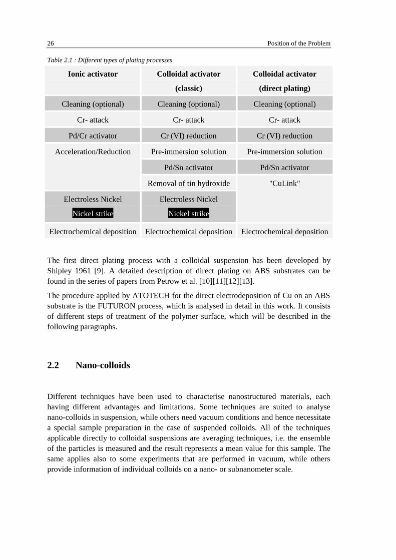
A further improvement of the plating process arose with the direct plating technique,which allowed omitting the electroless deposition of nickel. The whole process istherefore faster and easier to handle, since there are less chemical baths to control andsupervise. Furthermore the direct process is cheaper and better for the environment.Table 2.1 shows schematically the different possibilities of catalyse a non-conductivepolymer surface (ionic activator, colloidal activator, and direct process with thecolloidal activator).
26 Position of the Problem
Table 2.1 : Different types of plating processes
Ionic activator Colloidal activator
(classic)
Colloidal activator
(direct plating)
Cleaning (optional) Cleaning (optional) Cleaning (optional)
Cr- attack Cr- attack Cr- attack
Pd/Cr activator Cr (VI) reduction Cr (VI) reduction
Pre-immersion solution Pre-immersion solution
Pd/Sn activator Pd/Sn activator
Acceleration/Reduction
Removal of tin hydroxide
Electroless Nickel
Nickel strike
Electroless Nickel
Nickel strike
"CuLink"
Electrochemical depositionElectrochemical depositionElectrochemical deposition
The first direct plating process with a colloidal suspension has been developed byShipley 1961 [9]. A detailed description of direct plating on ABS substrates can befound in the series of papers from Petrow et al. [10][11][12][13].
The procedure applied by ATOTECH for the direct electrodeposition of Cu on an ABSsubstrate is the FUTURON process, which is analysed in detail in this work. It consistsof different steps of treatment of the polymer surface, which will be described in thefollowing paragraphs.
2.2 Nano-colloids
Different techniques have been used to characterise nanostructured materials, eachhaving different advantages and limitations. Some techniques are suited to analysenano-colloids in suspension, while others need vacuum conditions and hence necessitatea special sample preparation in the case of suspended colloids. All of the techniquesapplicable directly to colloidal suspensions are averaging techniques, i.e. the ensembleof the particles is measured and the result represents a mean value for this sample. Thesame applies also to some experiments that are performed in vacuum, while othersprovide information of individual colloids on a nano- or subnanometer scale.

Position of the Problem 27
2.2.1 Nano-Colloids in Suspension
Pd/Sn activator solutions:
Cohen and West have characterised a colloidal suspension very similar to that studied inthis work with Mössbauer spectroscopy [2][3][14][1]. This technique gives access tochemical information, like the oxidation state of Pd and Sn, averaged over the wholeensemble of colloids in suspension. They showed for the first time that the Pd/Sn-solutions used for the plating of polymers consist of nano-colloids of around 2 nm andnot of Pd-Sn complexes as suggested from other groups [15][16], which lead to aanimated discussion about the nature of the activator solution in the literature [17][18].The Mössbauer experiments were carried out on frozen solutions. They showed thatcomplexes present in solution are preserved in the frozen preparation if care has beentaken to prevent precipitation and clustering, e.g. by adding glass forming agents [2].Mostly solutions with a much lower Sn contents than for the FUTURON solution havebeen studied (Sn/Pd ≥ 1.5 while in the FUTURON, Sn/Pd ≈ 60). By comparingcentrifuged solutions with the original ones, they concluded that a Sn2+ layer stabilisesthe colloid and that the tin ions are part of [SnCl3]
- complexes, with the Sn2+ ion bondedto the core of the particle. The shape of the [SnCl3]
- complexes is described as a talltetrahedron with one ion at each corner, with a Sn-Cl bond distance of 2.5 Å and a bondangle Cl-Sn-Cl of appx. 90° [3]. The Sn concentration in the core has been estimated tobe max. 15 atomic %.
The colloid formation process has also been analysed by Mössbauer spectroscopy [14].The formation of different Pd-Sn complexes has been shown before the colloid isformed. The Pd-Sn complexes (denoted (Pd-Sn)c) are transformed according to thefollowing formula:
(Pd-Sn)c → Pdmetal + Sn4+ + 2 Sn2+ ( 2.1 )
The palladium is reduced by Sn2+, which is on his part transformed to Sn4+. Theremaining Sn2+ ions are used to stabilise the colloid. The size of the colloids isdetermined by the excess of Sn2+. The more Sn2+ ions are in the solution, the smaller thecolloids can be, since many small colloids have a larger surface area than few large onesand need therefore more ions for stabilisation.
Furthermore, they showed that the core of the colloids consists of a Pd rich phase. Theysuggested that the core is composed from a solid solution of Sn in Pd of about 18 %.
Other colloidal solutions:
Different X-ray techniques have also been applied to the characterisation of nano-colloids in suspension. Thurn-Albrecht et al. [19] used Small Angle X-ray Scattering(SAXS) and X-ray Photon Correlation Spectroscopy (XPCS) to study the size and thehydrodynamic radius of sterically stabilised palladium colloids.
28 Position of the Problem
Kutsch et al. [4] used SAXS to determine the particle radius and the thickness of thestabilising surfactant layer of gold colloids.
2.2.2 Colloidal stability
Colloids in suspension have to be stabilised to prevent agglomeration and segregation.This can be done in two ways: steric stabilisation and charge stabilisation [20].
Sterically stabilised colloids are protected by a surfactant (an organic molecule) whichis absorbed on the surface on the colloids. If two colloids approach each other, thesurfactant layers act as a buffer and prevent the agglomeration.
In the second case of stabilisation, the surface of the colloids is charged. Since allcolloids carry the same charge, they repel each other by electrostatic interactions. Thecolloidal surface can be charged in different ways, depending on the nature of thecolloid. The three mayor possibilities are:
• Ionic crystals as AgI can be charged by preferential dissolution of certain atoms.This produces crystal lattice defects at the surface of one type of ion. This "unequalhydration" produces for example for AgI colloids in water a I- excess at the surfaceand hence a negative surface charge [21].
• Preferential absorption of certain ions of the suspension on the colloid. This can beobserved for example for Al2O3 in a NaCl [22]. Surface AlOH sites dissociate andform AlOH2
+, AlOH2+Cl-, AlO- or AlO-Na+.
• Surface dissociation, for example in silica particles in water [21]. The surface ofsilica consists of SiO- and Si+ ions. In water, they form hydroxyl groups (SiOH),followed by dissociation of H+ or OH-, depending on the pH value. This processtakes also plase in most metal-oxide colloids.
Ions can be adsorbed in different way from solution on a surface: either they are stillsurrounded by water molecules (hydrated) or they lose that shell and get directly incontact with the surface (contact absorption). It depends on the free-energy change ifions are contact absorbed or not. Cl- ions lose free energy on contact absorption on anelectrode ([23] p. 743).
The stability of a colloidal suspension is often described in terms of the Derjaguin-Landau-Verwey-Overbeek (DLVO)-theory [24]. The DLVO-potential is assumed torepresent electrostatic interactions between charged colloids: a repulsive screenedCoulomb potential which dominates at short distances and a long ranged attractive Vander Waals potential.
The Debye screening length: The Debye screening length 1/κ describes the distance,in which the charges of the colloid are screened by counter ions of the solution. This
Position of the Problem 29
screening length is typically in the range of few nm. The Debye screening length 1/κ isdefined as
2/1
*0
0
)²(
1
=
∑i ii
Br
cez
Tkεεκ
( 2.2)
where ε0=8.85 x 10⁻¹²As/Vm is the permittivity in vacuum, εr the relative electricpermittivity, T is the temperature in K, kB=1.38 x 10⁻²³J/K the Boltzmann constant. cio
*
are the concentrations of the participating ions (per m3), zi the valency of the ions and ethe charge of an electron (e=1.6 x 10⁻¹⁹C). In the case of the Pd/Sn activator solutions,the Debye screening length is about 0.1 nm.
The Interaction Potential: The electrostatic interaction of two charged colloids can bedescribed as a double layer repulsion between the two surfaces and Van der Waalsattraction. The double layer repulsion can be described by a size corrected Yukawapotential Uscy(r) [25].
r
e
a
eZerU
ra
rscy
κκ
κεπε
−
⋅
+
=2
0 14
²)( ( 2.3 )
where Z is the charge on the colloid and a its radius.
The Van der Waals attraction for two spherical particles is described by the potentialUVdW (r) [26]:
−++
−−=
²
²4²ln
²
²2
²4²
²2
6)(
r
ar
r
a
ar
aArU H
VdW ( 2.4)
where AH , the Hamaker constant, is of the order of 10-20J.
So the complete electrostatic interaction potential UDLVO (r) between two chargedcolloids is:
)()( rUrUU scyVdWDLVO += ( 2.5)
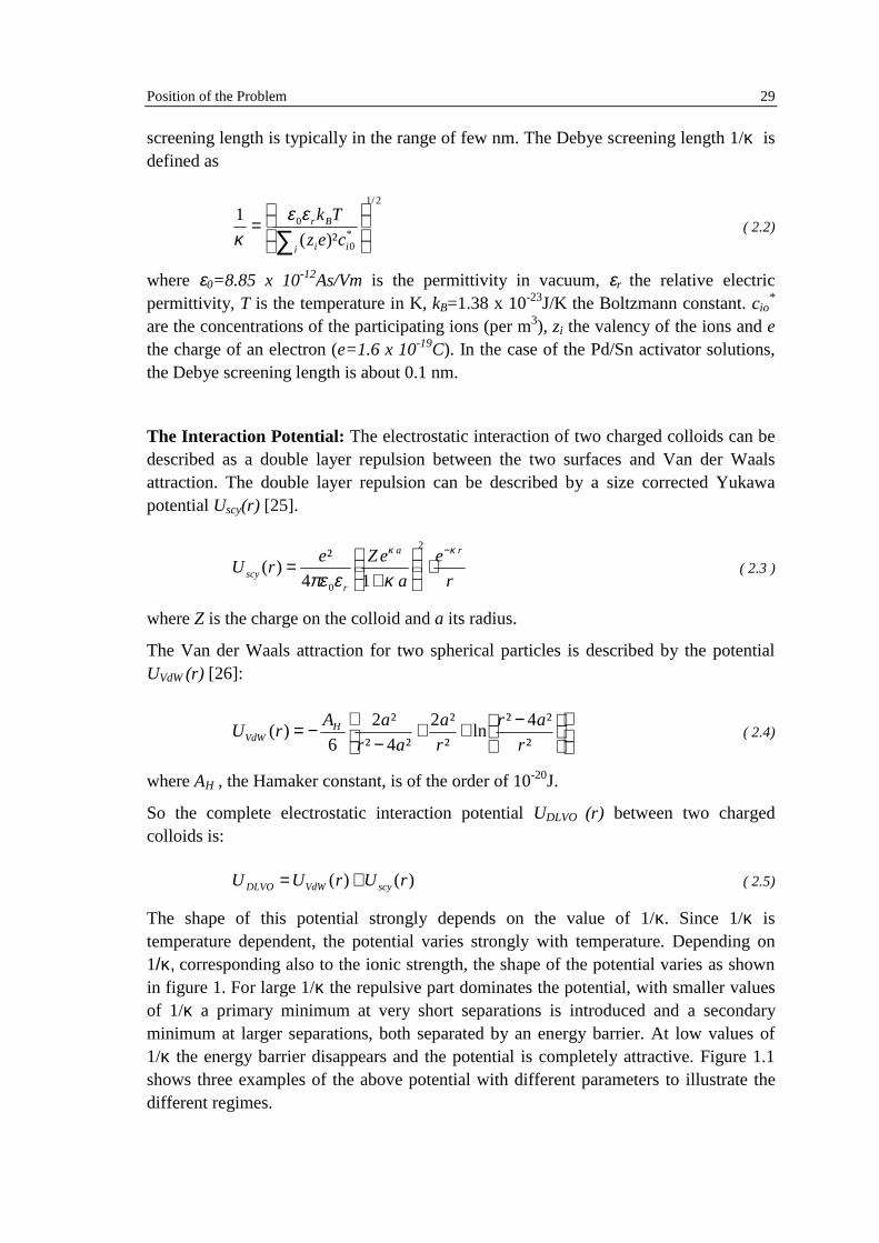
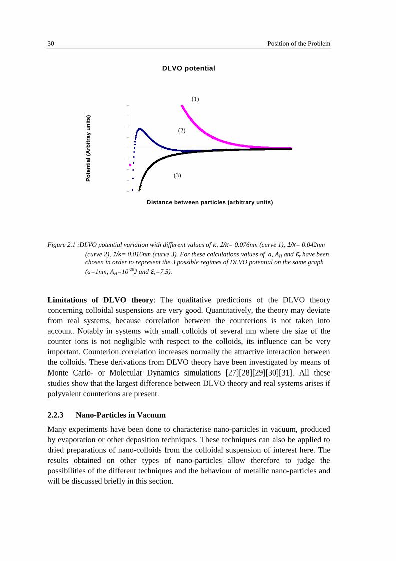
The shape of this potential strongly depends on the value of 1/κ. Since 1/κ istemperature dependent, the potential varies strongly with temperature. Depending on1/κ, corresponding also to the ionic strength, the shape of the potential varies as shownin figure 1. For large 1/κ the repulsive part dominates the potential, with smaller valuesof 1/κ a primary minimum at very short separations is introduced and a secondaryminimum at larger separations, both separated by an energy barrier. At low values of1/κ the energy barrier disappears and the potential is completely attractive. Figure 1.1shows three examples of the above potential with different parameters to illustrate thedifferent regimes.
30 Position of the Problem
DLVO potential
-2E-20
-1.5E-20
-1E-20
-5E-21
0
5E-21
1E-20
1.5E-20
2E-20
Distance between particles (arbitrary units)
Pot
entia
l (A
rbitr
ay u
nits
)
(3)
(2)
(1)
Figure 2.1 :DLVO potential variation with different values of κ. 1/κ= 0.076nm (curve 1), 1/κ= 0.042nm
(curve 2), 1/κ= 0.016nm (curve 3). For these calculations values of a, AH and εr have beenchosen in order to represent the 3 possible regimes of DLVO potential on the same graph
(a=1nm, AH=10-20J and εr=7.5).
Limitations of DLVO theory : The qualitative predictions of the DLVO theoryconcerning colloidal suspensions are very good. Quantitatively, the theory may deviatefrom real systems, because correlation between the counterions is not taken intoaccount. Notably in systems with small colloids of several nm where the size of thecounter ions is not negligible with respect to the colloids, its influence can be veryimportant. Counterion correlation increases normally the attractive interaction betweenthe colloids. These derivations from DLVO theory have been investigated by means ofMonte Carlo- or Molecular Dynamics simulations [27][28][29][30][31]. All thesestudies show that the largest difference between DLVO theory and real systems arises ifpolyvalent counterions are present.
2.2.3 Nano-Particles in Vacuum
Many experiments have been done to characterise nano-particles in vacuum, producedby evaporation or other deposition techniques. These techniques can also be applied todried preparations of nano-colloids from the colloidal suspension of interest here. Theresults obtained on other types of nano-particles allow therefore to judge thepossibilities of the different techniques and the behaviour of metallic nano-particles andwill be discussed briefly in this section.
Position of the Problem 31
Experimental Characterisation of nano-objects:
One very powerful experimental technique for obtaining local information about nano-colloids is the transmission electron microscopy, which is also used in this work. Pd-Sncolloidal systems have been studied e.g. by Froment et al [32], who showed thatdifferent preparation conditions change some properties of the colloids. The temperatureduring colloid formation, the pH value and the reaction time have been established ascrucial parameters. The structure and shape of many other types of nano-colloids havealso been investigated with TEM. Fuchs et al. used microsupports to observe the shapeof palladium colloids in three dimensions [33].
HRTEM has also been successfully applied to investigate the structure of Pd-Cuparticles of several nanometers and its orientation on a MgO substrate as well as itspreferred surface facets [34].
Bimetallic Pt-Sn catalysts have been characterised by EXAFS and XANES [35]. It hasbeen supposed that small Pt-Sn clusters are anchored to the Al2O3-support by Pt-O-Sn2+
bridges. For the same system, only Sn2+ bridges have been supposed to be responsiblefor the bonding between the catalyst and the alumina support [36]. They observed thatthe Pt is more highly dispersed in the presence of Sn and suggested that Pt particles aresurrounded by a Sn2+ shell. Furthermore, they excluded Sn4+ to be present at the surface.On a SiO2 substrate, they observed the formation of bimetallic Pt-Sn entities and muchless oxidised tin.
EELS in an electron microscope gives access to the chemical composition of the sampleand, if it is used with a nano-probe, provides a very high spatial resolution. Line-scantechniques or energy-filtered imaging has been employed to analyse different kinds ofnano-objects. EELS is especially suited for chemical analysis because of the highsensibility (much higher than for EDX, for example). Krivanek et al. reported thequantification of EELS spectra near the single atom detection limit [37]. EELS line-scans served to observe different collective excitation modes in carbon nanotubes [38].Energy filtered imaging in a Cryo-TEM has been used to analyse palladium colloidswith a diameter of 10-20 nm in ice [39].
Metallic Core-Shell Colloid:
Transmission electron microscopy served also to observe bimetallic core-shell colloids.Optical spectroscopy, TEM and HRTEM has been used to analyse the optical andstructural properties of gold coated silver particles of about 10 nm [40]. The sametechniques have been also applied to gold-tin colloids, which show in some casesuniformly alloyed AuSn particles, in others a core consisting of AuSn and an gold-richouter layer [41]. In both cases, the shell was thick enough (several atomic layers) toanalyse its crystal structure by FFT of HRTEM-images. The evolution of the Ag surface
32 Position of the Problem
plasmon in optical spectroscopy showed that colloids in solutions of lead and silverhave a core shell structure with a silver core and a Pb shell [42].
Au-Ag bimetallic nanoparticles have been observed with TEM, XPS, FTIR and opticalspectroscopy [43]. The FTIR experiments showed that CH2 groups at the surface of thecolloids are bonded to Ag, hence the colloids must have a core-shell structure with asilver enrichment at the surface. The XPS peak intensities for Au and Ag did not reflectthe nominal composition of Ag and Au of their samples, the Ag peak having always atoo high intensity. This confirmed the FTIR experiments and shows that the Ag is morelikely to be at the surface than Au.
Thermodynamic Studies and Monte Carlo Simulations:
In most bimetallic systems, one species tends to segregate at the surface in order tominimise the surface energy. Surface segregation in bimetallic colloids has been studiedextensively for noble metals ([44][45][46][47][48]) and compared to experiment.Mainly bimetallic clusters composed from transition metals from the groups 9-11 fromthe periodic table, which have a densely packed structure (e.g. Pd, Pt, Cu, Au, Ag), havebeen investigated. Monte Carlo (MC) simulations have been used to minimise theinternal energy. The interaction between atoms in the cluster is described by anempirical potential. For an arbitrary pair of atoms, the position of the atoms is switchedand the change in configurational energy is calculated. If the energy of the system isdiminished by switching the atomic position, the atoms are exchanged. Then, the nextpair of atoms is selected. Different interaction potentials have been used in literature.For example, Strohl and King [47] used a "surface-modified pair potential model"(SMPP). Only nearest neighbour interactions are considered there and theconfigurational energy of an atom is equally distributed amongst the nearest neighbours.Other methods are the Tight Binding model in the second moment approximation (TB-SMA) or an empirically modified version (MTB) [44],[45]. Systems like Pd-Sn are notsuitable for MC-simulations due to the high number of distinct crystal structures of Pdand Sn (Figure 2.3), which are mostly not densely packed structures. But since thesurface energy of the two metals is very different, one might expect that the surfacesegregating species is Sn with the lower surface energy. The surface tension of metals inthe liquid phase can be calculated with the following formula [49]:
n
cT
TA
−= 1σ ( 2.6 )
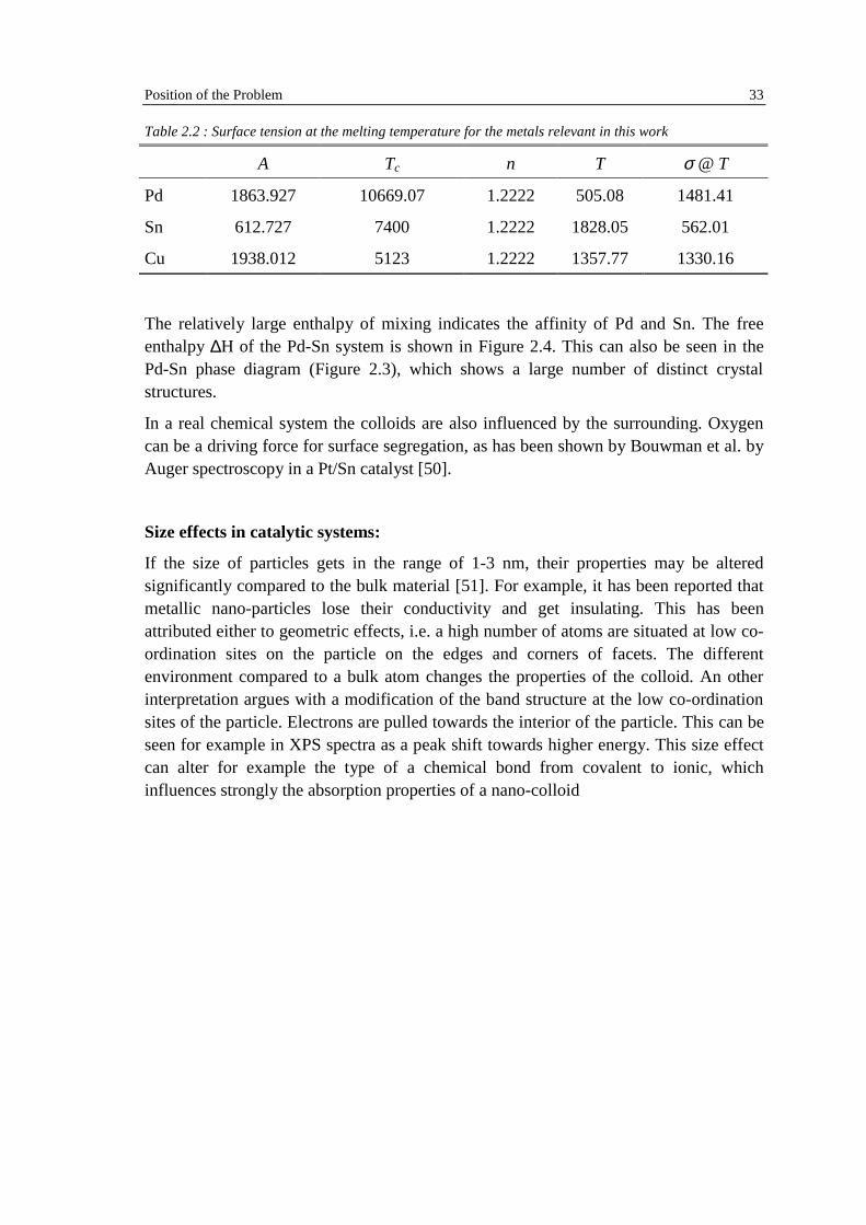
where σ is the surface tension in dynes/cm, T the temperature in K. The values of theconstants A, Tc and n and the surface tension corresponding to the melting temperaturecan be found in the following table [49].
Position of the Problem 33
Table 2.2 : Surface tension at the melting temperature for the metals relevant in this work
A Tc n T σ @ T
Pd 1863.927 10669.07 1.2222 505.08 1481.41
Sn 612.727 7400 1.2222 1828.05 562.01
Cu 1938.012 5123 1.2222 1357.77 1330.16
The relatively large enthalpy of mixing indicates the affinity of Pd and Sn. The freeenthalpy ∆H of the Pd-Sn system is shown in Figure 2.4. This can also be seen in thePd-Sn phase diagram (Figure 2.3), which shows a large number of distinct crystalstructures.
In a real chemical system the colloids are also influenced by the surrounding. Oxygencan be a driving force for surface segregation, as has been shown by Bouwman et al. byAuger spectroscopy in a Pt/Sn catalyst [50].
Size effects in catalytic systems:
If the size of particles gets in the range of 1-3 nm, their properties may be alteredsignificantly compared to the bulk material [51]. For example, it has been reported thatmetallic nano-particles lose their conductivity and get insulating. This has beenattributed either to geometric effects, i.e. a high number of atoms are situated at low co-ordination sites on the particle on the edges and corners of facets. The differentenvironment compared to a bulk atom changes the properties of the colloid. An otherinterpretation argues with a modification of the band structure at the low co-ordinationsites of the particle. Electrons are pulled towards the interior of the particle. This can beseen for example in XPS spectra as a peak shift towards higher energy. This size effectcan alter for example the type of a chemical bond from covalent to ionic, whichinfluences strongly the absorption properties of a nano-colloid

34 Position of the Problem
Figure 2.2: Pd-Sn phase diagram showing a high number of different phases [52]
0.0 0.2 0.4 0.6 0.8 1.0
-16-14-12-10
-8-6-4-20
∆H (
kca
l/g-a
tom
)
Atomic Percent Tin
Figure 2.4: Free Enthalpy of the Pd-Sn system at 320 K [53]. The data points are measured values, thecurve is a guide to the eye
Position of the Problem 35
2.3 Direct Plating
2.3.1 Overview
The following paragraphs describe the different steps of the FUTURON process, whichcorresponds to the direct plating process schematically represented in Table 2.1. Workhas been published on direct plating processes similar to the FUTURON process (seereferences in chapters 2.2.5 and 2.2.6). These results will also shortly be discussed here.
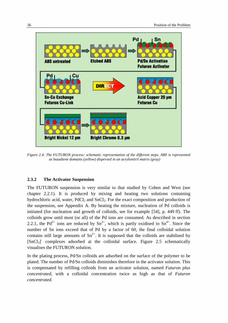
The direct plating process can only be applied to certain polymers. The most importantone is ABS. The description below focuses on this polymer. The polymer to be platedhas to pass different baths which all are kept at an optimal temperature. The temperatureand the dwell time for each bath have been optimised in the industrial process. Table 2.3lists all the steps of the FUTURON process up to the plating of copper. ABS plates of10x15 cm have been used as test plates for the different steps. Figure 2.4 showsschematically the different steps of the plating process.
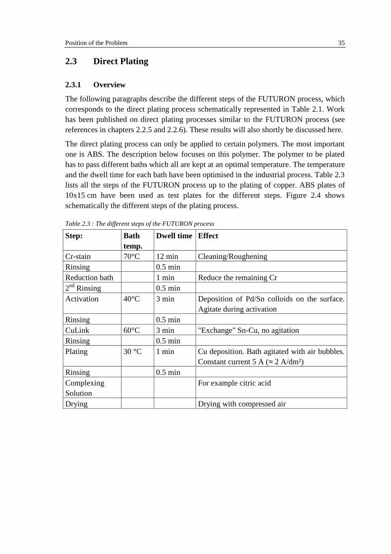
Table 2.3 : The different steps of the FUTURON process
Step: Bathtemp.
Dwell time Effect
Cr-stain 70°C 12 min Cleaning/RougheningRinsing 0.5 minReduction bath 1 min Reduce the remaining Cr2nd Rinsing 0.5 minActivation 40°C 3 min Deposition of Pd/Sn colloids on the surface.
Agitate during activationRinsing 0.5 minCuLink 60°C 3 min "Exchange" Sn-Cu, no agitationRinsing 0.5 minPlating 30 °C 1 min Cu deposition. Bath agitated with air bubbles.
Constant current 5 A (≈ 2 A/dm²)Rinsing 0.5 minComplexingSolution
For example citric acid
Drying Drying with compressed air
36 Position of the Problem
Figure 2.4: The FUTURON process: schematic representation of the different steps. ABS is representedas butadiene domains (yellow) dispersed in an acrylonitril matrix (gray)
2.3.2 The Activator Suspension
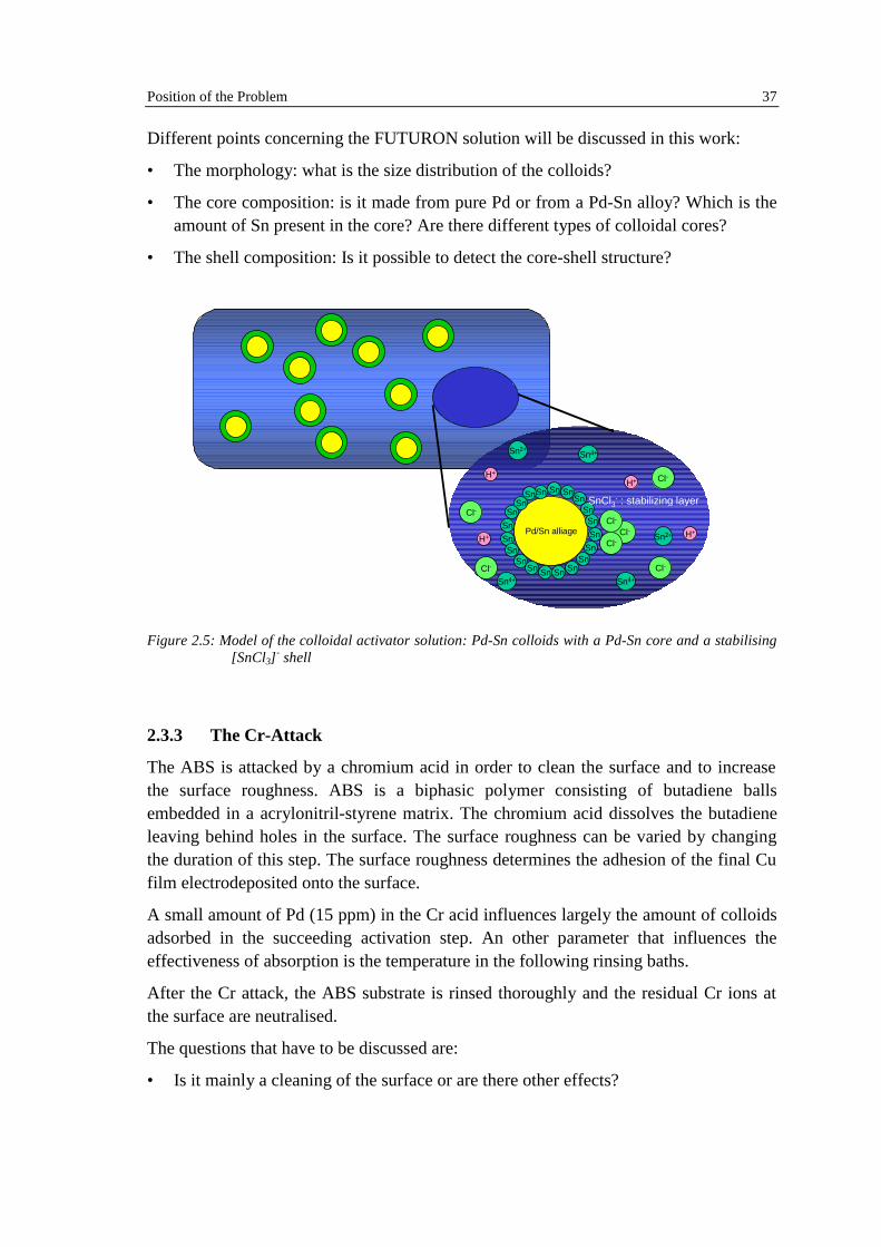
The FUTURON suspension is very similar to that studied by Cohen and West (seechapter 2.2.1). It is produced by mixing and heating two solutions containinghydrochloric acid, water, PdCl2 and SnCl2. For the exact composition and production ofthe suspension, see Appendix A. By heating the mixture, nucleation of Pd colloids isinitiated (for nucleation and growth of colloids, see for example [54], p. 449 ff). Thecolloids grow until most (or all) of the Pd ions are consumed. As described in section2.2.1, the Pd2+ ions are reduced by Sn2+, which is partly oxidised to Sn4+. Since thenumber of Sn ions exceed that of Pd by a factor of 60, the final colloidal solutioncontains still large amounts of Sn2+. It is supposed that the colloids are stabilised by[SnCl3]
- complexes adsorbed at the colloidal surface. Figure 2.5 schematicallyvisualises the FUTURON solution.
In the plating process, Pd/Sn colloids are adsorbed on the surface of the polymer to beplated. The number of Pd/Sn colloids diminishes therefore in the activator solution. Thisis compensated by refilling colloids from an activator solution, named Futuron plusconcentrated, with a colloidal concentration twice as high as that of Futuronconcentrated.
Position of the Problem 37
Different points concerning the FUTURON solution will be discussed in this work:
• The morphology: what is the size distribution of the colloids?
• The core composition: is it made from pure Pd or from a Pd-Sn alloy? Which is theamount of Sn present in the core? Are there different types of colloidal cores?
• The shell composition: Is it possible to detect the core-shell structure?
Pd/Sn alliageSnSn
SnSnSnSn
SnSnSnSn
Sn
Sn
SnSn
Sn
SnSn
SnSn
Sn
H+
H+H+
H+
Cl- Cl-
Cl-
Cl-
Cl-Cl-
Cl-
Sn2+
Sn2+
Sn4+Sn4+
Sn4+
SnCl3- : stabilizing layer
Figure 2.5: Model of the colloidal activator solution: Pd-Sn colloids with a Pd-Sn core and a stabilising[SnCl3]
- shell
2.3.3 The Cr-Attack
The ABS is attacked by a chromium acid in order to clean the surface and to increasethe surface roughness. ABS is a biphasic polymer consisting of butadiene ballsembedded in a acrylonitril-styrene matrix. The chromium acid dissolves the butadieneleaving behind holes in the surface. The surface roughness can be varied by changingthe duration of this step. The surface roughness determines the adhesion of the final Cufilm electrodeposited onto the surface.
A small amount of Pd (15 ppm) in the Cr acid influences largely the amount of colloidsadsorbed in the succeeding activation step. An other parameter that influences theeffectiveness of absorption is the temperature in the following rinsing baths.
After the Cr attack, the ABS substrate is rinsed thoroughly and the residual Cr ions atthe surface are neutralised.
The questions that have to be discussed are:
• Is it mainly a cleaning of the surface or are there other effects?
38 Position of the Problem
• Is the absorption of the colloids in the following activation step influenced by theattack? Does it produce active sites on the surface for the activation?
2.3.4 The Activation Step
The activator solution consists of bimetallic Pd-Sn colloids in an acid solution, asdescribed in section 2.2.1. The ABS plate is immerged into the solution. Pd-Sn colloidsare deposited on the surface of the polymer.
The temperature of the activator bath is influencing the amount of colloids adsorbed onthe surface. The optimal temperature for the process is at about 40°C. After 3 minutes,the adsorbed layer is sufficient for an effective metallisation. The colloid concentrationin the activator bath is kept constant by filling it up with a more concentrated colloidalsolution.
Cohen and West proposed that some Sn2+ ions of the stabilising layer of the colloids areoxidised by oxygen absorbed on the substrate in the pre-activation steps [55]. Only onemonolayer of Sn2+ has been absorbed in their experiments.
The following questions will be discussed in this work:
• Is there a multilayer absorption of colloids? If yes, why
• What is the composition of the adsorbed layer?
• What are the benefits of Pd and Sn?
2.3.5 The Acceleration Step: CuLink
The acceleration takes place in an alkali (base) bath, containing copper ions (Cu2+). TheABS plate with the layer of adsorbed colloids is immerged for several minutes(typically 3 min). Part of the Sn is removed and "replaced" by Cu, which enhances theconductivity of the surface. It is suggested that the Cu2+ ions are reduced to Cu+ by Sn2+
coming from the protective shell around the colloids, which is on his own oxidised toSn4+and is dissolved. Since Cu+ is not stable in this environment, it decomposes tometallic Cu and Cu2+. This procedure has therefore "cracked" the shell around thecolloids and placed metallic Cu on the surface. This connects the Pd colloids on theABS surface and improves therefore the conductivity of the surface film [7].
The exchange of the Sn ions by Cu accelerates the propagation of the metal front in thedirect plating process. This has been reported for example by Okabayashi [56]
Some authors reported the formation of Cu clusters after the "acceleration step" andproposed that these clusters are the driving force for accelerating the plating step [57].According to this author, they serve as subsequently activated microelectrodes for theplating. The mechanism called "Modified Stepwise Propagation" will be described inmore detail in section 2.3.6.

Position of the Problem 39
There exist other possibilities of "acceleration", based on sulphur [58][59][60]. The tinis also removed in this process, but "replaced" by sulphur, which acts as a bridgingligand between the remaining Pd core of the colloid and the first copper ions arriving atthe surface in the plating step.
The discussion will focus on:
• What is exchanged?
• How does the exchange take place?
• Does the morphology of the colloidal layer change? How?
2.3.6 The Plating Step
The final step is the electrochemical deposition of the Cu film onto the conducting layerat the ABS surface. After the acceleration, the ABS-plate is contacted with an electrodeand immerged in the plating bath, and at high current densities (about 2 A/dm²) a thinlayer of Cu is deposited onto the plastics surface, starting at the electrode contacts andthen spreading over the plate. After about 1 min all the surface is recovered by auniform Cu layer.
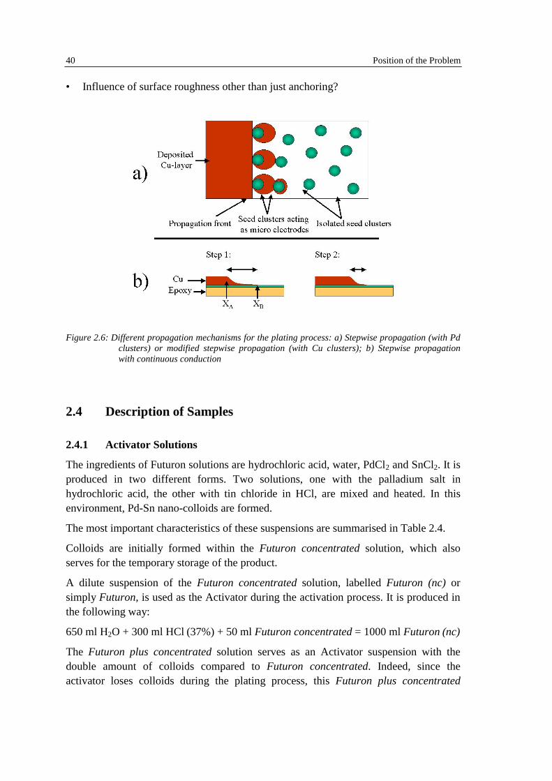
An open question is the mechanism of propagation of the Cu front in the plating step.Different propagation mechanisms have been discussed in the literature: Weng andLandau proposed a "stepwise propagation" mechanism [61]. A "stepwise propagationwith continuous conduction" model has been suggested by Bladon et al. [62]. Ono et al.proposed a "modified stepwise propagation" mechanism [57][63].
Stepwise Propagation mechanism: Pd clusters adsorbed at the surface act as steppingstones for the propagation of the plating front. If the front gets in touch with a new Pdcluster, the latter acts as a microelectrode and promotes hence the propagation.
Stepwise propagation with continuous conduction: Since TEM images have proventhat the Pd/Sn colloids are not isolated clusters at the polymer surface but form acontinuous layer, this model has been proposed. The acceleration is achieved becausethe colloidal surface layer extends the equipotential surface where the potential issufficiently high for the Cu-deposition into the region of the plastics which has not yetbeen plated.
Modified stepwise propagation: Ono et al. observed large Cu-clusters on the polymersurface after the acceleration step, and proposed the same mechanism as Weng andLandau, only with the Cu clusters serving as stepping stones for the propagation.
Points, which have to be discussed concerning this step of the plating process, are:
• The plating mechanism: Which of the different models proposed corresponds best toreality: Stepwise propagation, Stepwise propagation with continuous conduction,modified stepwise propagation?
40 Position of the Problem
• Influence of surface roughness other than just anchoring?
Figure 2.6: Different propagation mechanisms for the plating process: a) Stepwise propagation (with Pdclusters) or modified stepwise propagation (with Cu clusters); b) Stepwise propagationwith continuous conduction
2.4 Description of Samples
2.4.1 Activator Solutions
The ingredients of Futuron solutions are hydrochloric acid, water, PdCl2 and SnCl2. It isproduced in two different forms. Two solutions, one with the palladium salt inhydrochloric acid, the other with tin chloride in HCl, are mixed and heated. In thisenvironment, Pd-Sn nano-colloids are formed.
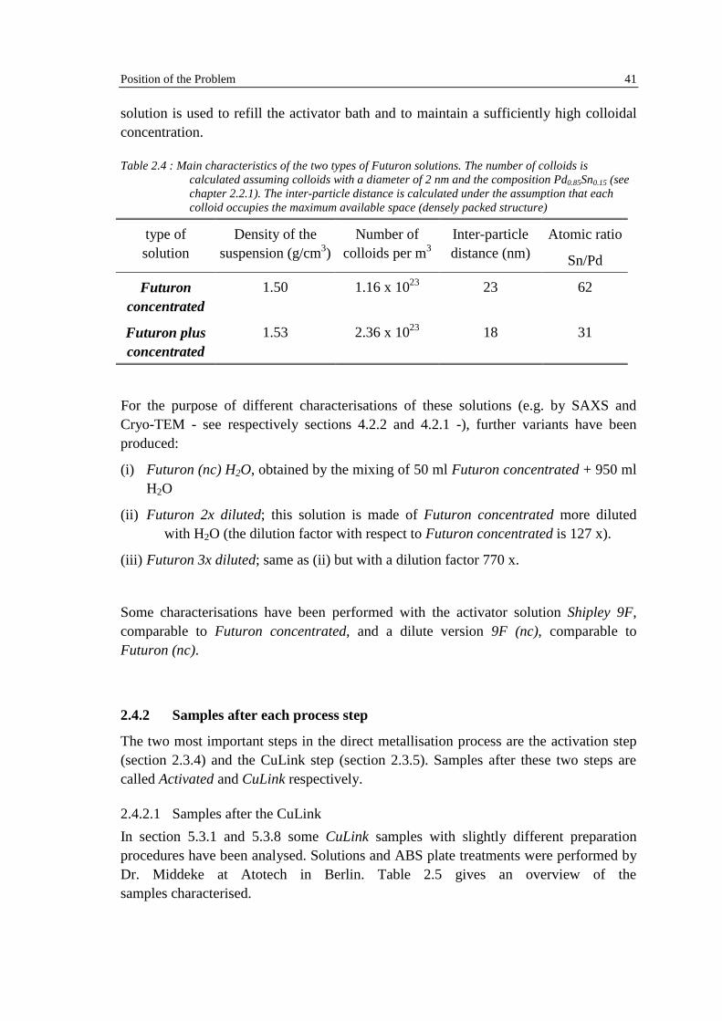
The most important characteristics of these suspensions are summarised in Table 2.4.
Colloids are initially formed within the Futuron concentrated solution, which alsoserves for the temporary storage of the product.
A dilute suspension of the Futuron concentrated solution, labelled Futuron (nc) orsimply Futuron, is used as the Activator during the activation process. It is produced inthe following way:
650 ml H2O + 300 ml HCl (37%) + 50 ml Futuron concentrated = 1000 ml Futuron (nc)
The Futuron plus concentrated solution serves as an Activator suspension with thedouble amount of colloids compared to Futuron concentrated. Indeed, since theactivator loses colloids during the plating process, this Futuron plus concentrated
Position of the Problem 41
solution is used to refill the activator bath and to maintain a sufficiently high colloidalconcentration.
Table 2.4 : Main characteristics of the two types of Futuron solutions. The number of colloids iscalculated assuming colloids with a diameter of 2 nm and the composition Pd0.85Sn0.15 (seechapter 2.2.1). The inter-particle distance is calculated under the assumption that eachcolloid occupies the maximum available space (densely packed structure)
type ofsolution
Density of thesuspension (g/cm3)
Number ofcolloids per m3
Inter-particledistance (nm)
Atomic ratio
Sn/Pd
Futuronconcentrated
1.50 1.16 x 10²³ 23 62
Futuron plusconcentrated
1.53 2.36 x 10²³ 18 31
For the purpose of different characterisations of these solutions (e.g. by SAXS andCryo-TEM - see respectively sections 4.2.2 and 4.2.1 -), further variants have beenproduced:
(i) Futuron (nc) H2O, obtained by the mixing of 50 ml Futuron concentrated + 950 mlH2O
(ii) Futuron 2x diluted; this solution is made of Futuron concentrated more dilutedwith H2O (the dilution factor with respect to Futuron concentrated is 127 x).
(iii) Futuron 3x diluted; same as (ii) but with a dilution factor 770 x.
Some characterisations have been performed with the activator solution Shipley 9F,comparable to Futuron concentrated, and a dilute version 9F (nc), comparable toFuturon (nc).
2.4.2 Samples after each process step
The two most important steps in the direct metallisation process are the activation step(section 2.3.4) and the CuLink step (section 2.3.5). Samples after these two steps arecalled Activated and CuLink respectively.
2.4.2.1 Samples after the CuLink
In section 5.3.1 and 5.3.8 some CuLink samples with slightly different preparationprocedures have been analysed. Solutions and ABS plate treatments were performed byDr. Middeke at Atotech in Berlin. Table 2.5 gives an overview of thesamples characterised.

42 Position of the Problem
Table 2.5 : Samples where the formation of Cu Clusters has been analysed
Solution Dwell time ABS plate reference
Futuron concentrated 3’ Fut3’
Futuron concentrated 7’ Fut7’
Futuron concentrated after a low temperaturetreatment
3’ FutLT3’
Futuron plus concentrated after a lowtemperature treatment
3’ FutLT+3’
Futuron concentrated with surfactant duringactivation step
3’ FutS3’
Futuron concentrated with surfactant duringactivation and Cu-link steps
3’ FutSx3’
Futuron on BOLTA substrate 7’ FutB7’
Shipley 9F (competitor's product) 3’ F9
The dwell time corresponds to the time of both activation and Cu-link steps. Forcomparison, the dwell time reported in the Sashiko Ono study is 7 minutes [57].
The solutions marked with « low temperature » were stored for 1 weekend at –10°C.
The FutSx3’ sample have been treated with a surfactant during the activation and Cu-link steps.