2-Port Self-acting Temperature Control Valve Selection for ...
17
Local regulations may restrict the use of this product to below the conditions quoted. In the interests of development and improvement of the product, we reserve the right to change the specification without notice. © Copyright 2021 Page 1 of 17 TI-S21-07 CTLS Issue 5 2-Port Self-acting Temperature Control Valve Selection for Heating and Cooling Applications How to select a system Valve selection: 1. Is the application for heating or cooling? A heating application will require a valve that is normally open and will close with rising temperature. A cooling application will require a valve that is normally closed and will open with rising temperature. 2. Is the valve to be used on steam or water applications? For steam applications use the sizing chart in Table 1. For water heating applications use the chart in Table 2. For water cooling applications use the chart in Table 3. 3. Determine the pressure upstream of the valve (P 1 ) for normal running conditions. 4. Determine the pressure downstream of the valve (P 2 ) for normal running conditions. 5. Determine the required flowrate of the steam or water. 6. Determine the size and basic type of control valve using the sizing charts in Tables 1, 2 and 3. A sizing example is illustrated for each of these charts under each of these Tables. Please note that at this point only the valve size and basic valve type has been selected. It is now necessary to refer to Tables 4, 5, and 6 to check the following: 7. What body material is required? Pressure temperature limitations for each material (gunmetal, cast iron and cast carbon steel) are shown in Table 4. Economics may also influence the choice of body material. 8. What end connections are required - screwed or flanged? Choices are shown in the valve selection Tables 5 and 6. 9. Normally closed valves may have a bleed which allows a small flow to reach the sensor so that it can react to a temperature rise. This will depend on the application. 10. What is the maximum differential pressure across the control valve? In a heating application with a normally open valve a rise in temperature at the sensor will cause the valve to close. In order to ensure that the valve closes fully the sensor must be able to overcome the force generated on the valve plug by the maximum differential pressure across the control valve (P 1 max - P 2 min). This is often substantially greater than the normal running pressure drop across the control valve. Similarly, for a cooling application using a normally closed valve, the return spring must be able to close the valve against the maximum differential pressure. The maximum differential pressure for each valve is shown in Tables 5 and 6. The maximum differential pressure of a valve may be increased by incorporating a balancing bellows, details of which are also indicated in Tables 5 and 6 under the column titled 'Balanced'. Differential pressure Please note: the pressures given on the sizing charts are in bar g only P P Control system selection and Typical order information are on page 2 See page 2 for Table locations
Transcript of 2-Port Self-acting Temperature Control Valve Selection for ...

Local regulations may restrict the use of this product to below the conditions quoted. In the interests of development and improvement of the product, we reserve the right to change the specification without notice. © Copyright 2021
Page 1 of 17
TI-S21-07 CTLS Issue 5
2-Port Self-acting TemperatureControl Valve Selection
for Heating and Cooling Applications
How to select a systemValve selection:1. Is the application for heating or cooling?
A heating application will require a valve that is normally open and will close with rising temperature. A cooling application will require a valve that is normally closed and will open with rising temperature.
2. Is the valve to be used on steam or water applications? For steam applications use the sizing chart in Table 1.For water heating applications use the chart in Table 2.For water cooling applications use the chart in Table 3.
3. Determine the pressure upstream of the valve (P1) for normal running conditions.
4. Determine the pressure downstream of the valve (P2) for normal running conditions.
5. Determine the required flowrate of the steam or water.
6. Determine the size and basic type of control valve using the sizing charts in Tables 1, 2 and 3. A sizing example is illustrated for each of these charts under each of these Tables.
Please note that at this point only the valve size and basic valve type has been selected. It is now necessary to refer to Tables 4, 5, and 6 to check the following:
7. What body material is required? Pressure temperature limitations for each material (gunmetal, cast iron and cast carbon steel) are shown in Table 4. Economics may also influence the choice of body material.
8. What end connections are required - screwed or flanged? Choices are shown in the valve selection Tables 5 and 6.
9. Normally closed valves may have a bleed which allows a small flow to reach the sensor so that it can react to a temperature rise. This will depend on the application.
10. What is the maximum differential pressure across the control valve? In a heating application with a normally open valve a rise in temperature at the sensor will cause the valve to close. In order to ensure that the valve closes fully the sensor must be able to overcome the force generated on the valve plug by the maximum differential pressure across the control valve (P1 max - P2 min). This is often substantially greater than the normal running pressure drop across the control valve. Similarly, for a cooling application using a normally closed valve, the return spring must be able to close the valve against the maximum differential pressure. The maximum differential pressure for each valve is shown in Tables 5 and 6. The maximum differential pressure of a valve may be increased by incorporating a balancing bellows, details of which are also indicated in Tables 5 and 6 under the column titled 'Balanced'.
Differential pressure
Please note: the pressures given on the sizing
charts are in bar g only
P P
Control system selection and Typical order informationare on page 2
See page 2 for Table locations
TI-S21-07 CTLS Issue 5
Page 2 of 17
2-Port Self-acting Temperature Control Valve Selection for Heating and Cooling Applications
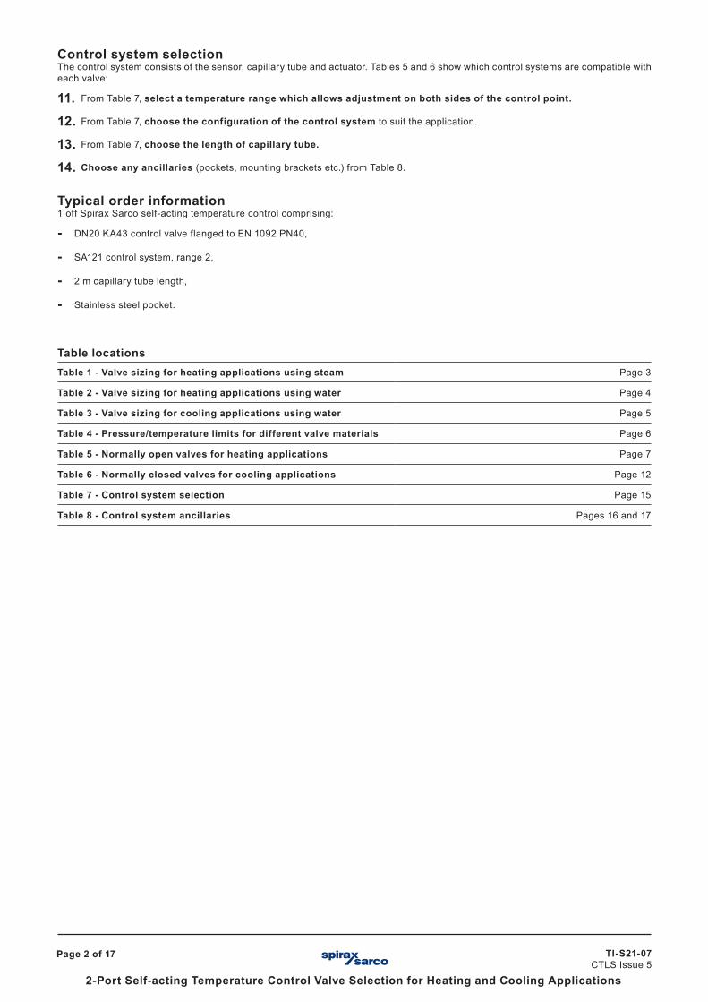
Control system selectionThe control system consists of the sensor, capillary tube and actuator. Tables 5 and 6 show which control systems are compatible with each valve:
11. From Table 7, select a temperature range which allows adjustment on both sides of the control point.
12. From Table 7, choose the configuration of the control system to suit the application.
13. From Table 7, choose the length of capillary tube.
14. Choose any ancillaries (pockets, mounting brackets etc.) from Table 8.
Typical order information1 off Spirax Sarco self-acting temperature control comprising:
- DN20 KA43 control valve flanged to EN 1092 PN40,
- SA121 control system, range 2,
- 2 m capillary tube length,
- Stainless steel pocket.
Table locationsTable 1 - Valve sizing for heating applications using steam Page 3
Table 2 - Valve sizing for heating applications using water Page 4
Table 3 - Valve sizing for cooling applications using water Page 5
Table 4 - Pressure/temperature limits for different valve materials Page 6
Table 5 - Normally open valves for heating applications Page 7
Table 6 - Normally closed valves for cooling applications Page 12
Table 7 - Control system selection Page 15
Table 8 - Control system ancillaries Pages 16 and 17

Page 3 of 17
2-Port Self-acting Temperature Control Valve Selection for Heating and Cooling Applications
TI-S21-07 CTLS Issue 5
Table 1 Valve sizing for heating applications using steamIn
let p
ress
ure
bar g
Ste
am fl
ow k
g/h
Critical pressure drop
Differential pressure bar
(P1 - P
2 )
A
B
C
D
EF
H
I
JKL, M
NOP
G
Kvs value
Size DN Type
A 0.38 15BX2/
BMF2/BM2
B 0.64 15BX3/
BMF3/BM3
C 1.03 15BX4/
BMF4/BM4
D 1.65 15BX6/
BMF6/BM6
E 2.58 15 SB
F 2.9 15 KA
G 3.86 20 SB
H 4.64 20 KA
I 6.8 25 SB
J 9.8 25 KA/KB
K 16.48 32 KA/KB/KC
L 16.48 40 KC
M 23.7 40 KA/KB
N 34 50 KA/KB/KC
O 65 65 NS
P 94 80 NSSizing example Given:
- Pressure at valve inlet P1 = 6 bar g
- Pressure at valve outlet P2 = 4 bar g
- The required steam flowrate = 280 kg / h
To size the valve:
1. Determine the differential pressure across the valve P1 - P2 = 6 - 4 = 2 bar.
2. Enter the upper section of the chart with the inlet pressure (P1) at 6 bar g and draw a horizontal line to intersect the differential pressure (P1 - P2) line at 2 bar. From this intersection draw a vertical line downwards.
3. Enter the lower section of the chart with the steam flowrate at 280 kg / h and draw a horizontal line to intersect the vertical line produced in step 2. From this intersection draw a line parallel to the diagonal lines in the direction of the valve selection box.
4 From the valve selection boxes choose the valve with the higher Kvs value i.e. size DN20 'KA' type valve with a Kvs of 4.64
Differential pressure
Flow
P P
TI-S21-07 CTLS Issue 5
Page 4 of 17
2-Port Self-acting Temperature Control Valve Selection for Heating and Cooling Applications
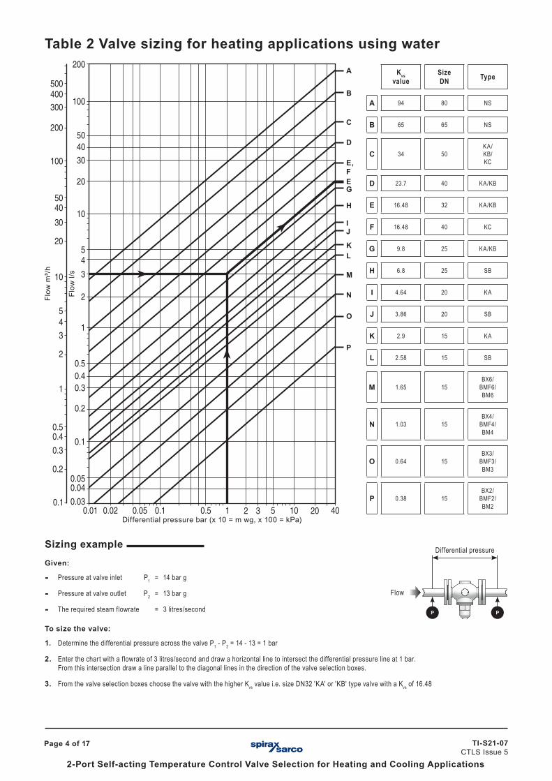
Table 2 Valve sizing for heating applications using waterFl
ow m
³/h
Differential pressure bar (x 10 = m wg, x 100 = kPa)� � ��
Flow
l/s
A
B
C
D
E, FE
H
IJ
KL
M
N
O
P
G
Sizing example Given:
- Pressure at valve inlet P1 = 14 bar g
- Pressure at valve outlet P2 = 13 bar g
- The required steam flowrate = 3 litres/second
To size the valve:
1. Determine the differential pressure across the valve P1 - P2 = 14 - 13 = 1 bar
2. Enter the chart with a flowrate of 3 litres/second and draw a horizontal line to intersect the differential pressure line at 1 bar.From this intersection draw a line parallel to the diagonal lines in the direction of the valve selection boxes.
3. From the valve selection boxes choose the valve with the higher Kvs value i.e. size DN32 'KA' or 'KB' type valve with a Kvs of 16.48
Kvs value
Size DN Type
A 94 80 NS
B 65 65 NS
C 34 50KA/KB/KC
D 23.7 40 KA/KB
E 16.48 32 KA/KB
F 16.48 40 KC
G 9.8 25 KA/KB
H 6.8 25 SB
I 4.64 20 KA
J 3.86 20 SB
K 2.9 15 KA
L 2.58 15 SB
M 1.65 15BX6/
BMF6/BM6
N 1.03 15BX4/
BMF4/BM4
O 0.64 15BX3/
BMF3/BM3
P 0.38 15BX2/
BMF2/BM2
Differential pressure
Flow
P P
Page 5 of 17
2-Port Self-acting Temperature Control Valve Selection for Heating and Cooling Applications
TI-S21-07 CTLS Issue 5
Differential pressure
Flow
P P
� � ��
Flow
m³/h
Flow
l/s
Differential pressure bar (x 10 = m wg, x 100 = kPa)
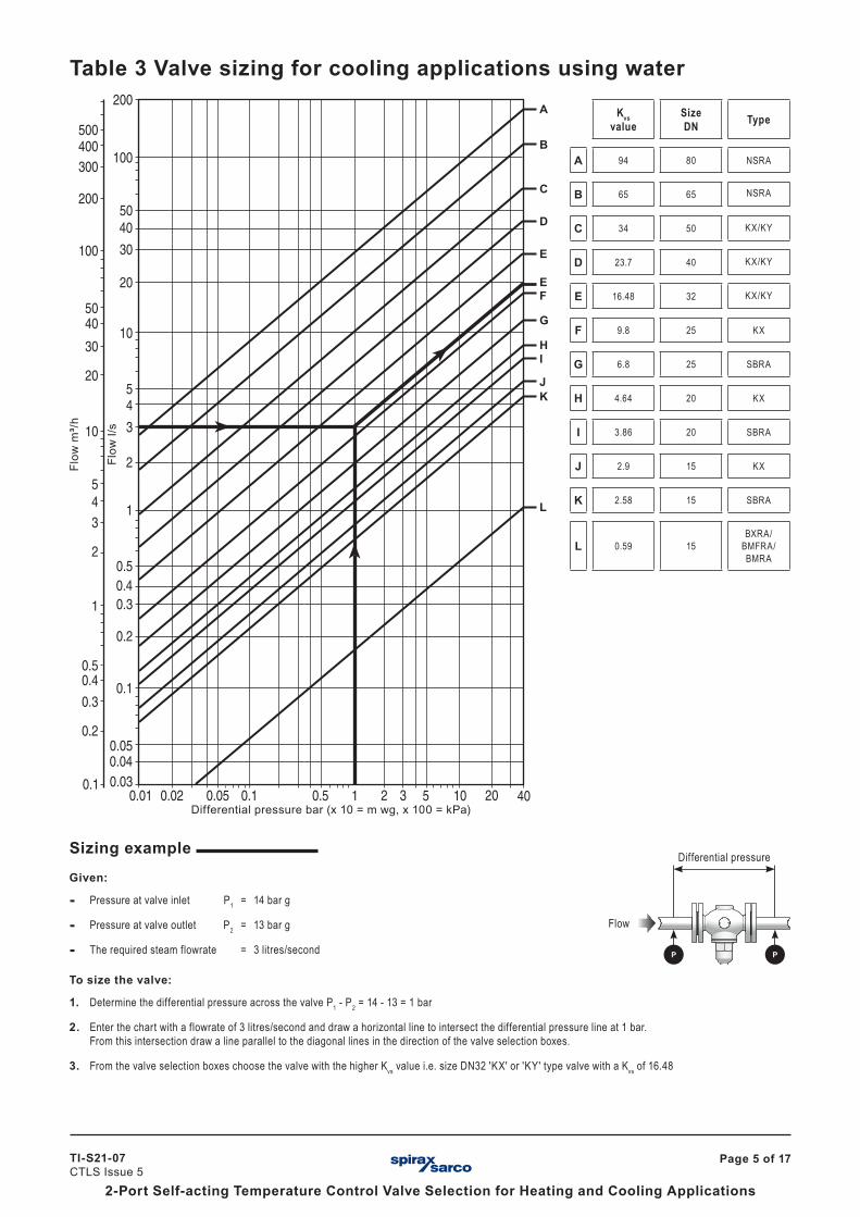
Table 3 Valve sizing for cooling applications using waterA
B
C
D
E
EF
HI
JK
L
G
Sizing example Given:
- Pressure at valve inlet P1 = 14 bar g
- Pressure at valve outlet P2 = 13 bar g
- The required steam flowrate = 3 litres/second
To size the valve:
1. Determine the differential pressure across the valve P1 - P2 = 14 - 13 = 1 bar
2. Enter the chart with a flowrate of 3 litres/second and draw a horizontal line to intersect the differential pressure line at 1 bar.From this intersection draw a line parallel to the diagonal lines in the direction of the valve selection boxes.
3. From the valve selection boxes choose the valve with the higher Kvs value i.e. size DN32 'KX' or 'KY' type valve with a Kvs of 16.48
Kvs value
Size DN Type
A 94 80 NSRA
B 65 65 NSRA
C 34 50 KX/KY
D 23.7 40 KX/KY
E 16.48 32 KX/KY
F 9.8 25 KX
G 6.8 25 SBRA
H 4.64 20 KX
I 3.86 20 SBRA
J 2.9 15 KX
K 2.58 15 SBRA
L 0.59 15BXRA/
BMFRA/BMRA

TI-S21-07 CTLS Issue 5
Page 6 of 17
2-Port Self-acting Temperature Control Valve Selection for Heating and Cooling Applications
00
50
100150200
260
5 10 15 20 25
00
50
100
150
200220
2 4 6 8 10 12 14 16
00
50100150200250300
10 20 30 40
0 10 20 30 37 400
50100150
200
260
Gunmetal
Tem
pera
ture
°C
Pressure bar g
Pressure bar g
Pressure bar g
Pressure bar g
Tem
pera
ture
°C
Cast carbon steel
Cast iron
Tem
pera
ture
°C
Table 4 Pressure/temperature limits for different valve materialsNote: Materials for the various valve types are shown in Tables 5 and 6 on the following pages.
Control valve body material Gunmetal Cast iron Cast carbon steel Stainless steel
Body design conditions PN25 PN16 PN25 PN40 PN40
Maximum design temperature 260 °C 220 °C 300 °C 300 °C 260 °C
Maximum cold hydraulic test 38 bar g 24 bar g 38 bar g 60 bar g 60 bar g
Stainless steel
Tem
pera
ture
°C
Steam saturation curve
Steam saturation curve
Steam saturation curve
Steam saturation curve
Note: The KB43 and KY43 control valves have a maximum design temperature limit of 232 °C.
Note: The KA61 and KA63 and KC63 control valves have a maximum design temperature limit of 232 °C.
Note: The KB51 and KY51 control valves have a maximum design temperature limit of 232 °C.
The product must not be used in this region.

Page 7 of 17
2-Port Self-acting Temperature Control Valve Selection for Heating and Cooling Applications
TI-S21-07 CTLS Issue 5
Valve selection dataTable 5 Normally open valves for heating applicationsFor pressure temperature relationships please refer to the pressure/temperature charts in Table 4.
*Please note:The KB31, KB33, KB43, and KB51 control valves can also be used on water applications where high P conditions exist.
KB33 (DN32 - DN50 flanged)*KB43 (DN32 - DN50 flanged)*KC43 (DN32 - DN50 flanged)KC63 (DN32 - DN50 flanged)
KA31 (DN32 - DN50 screwed)KA33 (DN32 - DN50 flanged)KA43 (DN15 - DN50 flanged)KA51 (DN32 - DN50 screwed)KA63 (DN15 - DN50 flanged)
NS (DN65 - DN80 flanged)NS (DN65 - DN80 screwed)
KB31 (DN32 - DN50 screwed)*KB51 (DN32 - DN50 screwed)*KC31 (DN40 - DN50 screwed)KC51 (DN40 - DN50 screwed)
KA31 (DN15 - DN25 screwed)KA33 (DN15 - DN25 flanged)KA51 (DN25 screwed)KA61 (DN15 - DN50 flanged)
SB (DN15 - DN25 screwed)
KB31 (DN25 screwed)*KB33 (DN25 flanged)KB51 (DN25 screwed)*
BM (DN15 flanged)BMF (DN15 flanged)BX (DN15 screwed)

TI-S21-07 CTLS Issue 5
Page 8 of 17
2-Port Self-acting Temperature Control Valve Selection for Heating and Cooling Applications
Gunmetal
Valve model
Size and pipe connections Control system options
ScrewedBSP/NPT
FlangedPN25/ANSI 150
Body design rating
Balanced Kvs Maximum P (bar)
Stroke mm
SA12
1
SA12
2
SA12
3
SA12
8
SA42
2
SA42
3
BX2 ½" PN25 0.38 17.2 2.2 • • • • • •
BX3 ½" PN25 0.64 17.2 3.2 • • • • • •
BX4 ½" PN25 1.03 17.2 3.2 • • • • • •
BX6 ½" PN25 1.65 17.2 3.2 • • • • • •
SB
½" PN25 2.58 17.2 3.2 • • • • • •
¾" PN25 3.86 10.3 4.0 • • • • • •
1" PN25 6.80 6.8 5.0 • • • • • •
KA51
1" PN25 9.80 4.5 5.6 • • • • • •
1¼" PN25 16.48 3.0 8.0 • • • •
1½" PN25 23.70 2.0 9.0 • • • •
2" PN25 34.00 1.5 9.5 • • • •
KB51*Balanced by phosphor bronze bellows
1" PN25 • 9.80 10.0 5.6 • • • • • •
1¼" PN25 • 16.48 9.0 8.0 • • • •
1½" PN25 • 23.70 8.2 9.0 • • • •
2" PN25 • 34.00 6.9 9.5 • • • •
KC51Balanced by stainless steel bellows
1½" PN25 • 16.48 16.0 9.0 • • • •
2" PN25 • 34.00 13.8 9.5 • • • •
NS double sealed valve
2½" DN65 PN25 65.00 10.0 9.5 • • • •
3" DN80 PN25 94.00 10.0 9.5 • • • •

Page 9 of 17
2-Port Self-acting Temperature Control Valve Selection for Heating and Cooling Applications
TI-S21-07 CTLS Issue 5
Cast iron
Valve model
Size and pipe connections Control system options
ScrewedBSP/NPT
FlangedPN16
Body design rating
Balanced Kvs Maximum P (bar)
Stroke mm
SA12
1
SA12
2
SA12
3
SA12
8
SA42
2
SA42
3
BMF2 DN15 PN16 0.38 16.0 2.2 • • • • • •
BMF3 DN15 PN16 0.64 16.0 3.2 • • • • • •
BMF4 DN15 PN16 1.03 16.0 3.2 • • • • • •
BMF6 DN15 PN16 1.65 16.0 3.2 • • • • • •
KA31 screwed and KA33 flanged
½" DN15 PN16 2.90 13.0 3.2 • • • • • •
¾" DN20 PN16 4.64 10.3 4.0 • • • • • •
1" DN25 PN16 9.80 4.5 5.6 • • • • • •
1¼" DN32 PN16 16.48 3.0 8.0 • • • •
1½" DN40 PN16 23.70 2.0 9.0 • • • •
2" DN50 PN16 34.00 1.5 9.5 • • • •
KB31* screwed and KB33* flanged balanced by phosphor bronze bellows
1" DN25 PN16 • 9.80 10.3 5.6 • • • • • •
1¼" DN32 PN16 • 16.48 9.0 8.0 • • • •
1½" DN40 PN16 • 23.70 8.2 9.0 • • • •
2" DN50 PN16 • 34.00 6.9 9.5 • • • •
KC31Balanced by stainless steel bellows
DN40 PN16 • 16.48 13.0 9.0 • • • •
DN50 PN16 • 34.00 13.0 9.5 • • • •

TI-S21-07 CTLS Issue 5
Page 10 of 17
2-Port Self-acting Temperature Control Valve Selection for Heating and Cooling Applications
Valve model
Size and pipe connectionsBody
design rating
Balanced KvsMaximum P (bar)
Stroke mm
Control system options
Flanged
SA12
1
SA12
2
SA12
3
SA12
8
SA42
2
SA42
3
PN25 PN40 ANSI 300
BM2 DN15 DN15 PN25 0.32 17.2 2.2 • • • • • •
BM3 DN15 DN15 PN40 0.64 17.2 3.2 • • • • • •
BM4 DN15 DN15 PN40 1.03 17.2 3.2 • • • • • •
BM6 DN15 DN15 PN40 1.65 17.2 3.2 • • • • • •
KA43
DN15 DN15 PN40 2.90 17.0 3.2 • • • • • •
DN20 DN20 PN40 4.64 10.0 4.0 • • • • • •
DN25 DN25 PN40 9.80 4.5 5.6 • • • • • •
DN32 DN32 PN40 16.48 3.0 8.0 • • • •
DN40 DN40 PN40 23.70 2.0 9.0 • • • •
DN50 DN50 PN40 34.00 1.5 9.5 • • • •
KB43*Balanced by phosphor bronze bellows
DN25 DN25 PN40 • 9.80 10.0 5.6 • • • • • •
DN32 DN32 PN40 • 16.48 9.0 8.0 • • • •
DN40 DN40 PN40 • 23.70 8.2 9.0 • • • •
DN50 DN50 PN40 • 34.00 6.9 9.5 • • • •
KC34Balanced by stainless steel bellows
DN32 DN32 PN40 • 16.48 16.0 8.0 • • • •
DN40 DN40 PN40 • 16.48 16.0 9.0 • • • •
DN50 DN50 PN40 • 34.00 13.8 9.5 • • • •
Cast carbon steel
Page 11 of 17
2-Port Self-acting Temperature Control Valve Selection for Heating and Cooling Applications
TI-S21-07 CTLS Issue 5
Valve model
Size and pipe connectionsBody
design rating
Balanced KvsMaximum P (bar)
Stroke mm
Control system options
SA12
1
SA12
2
SA12
3
SA12
8
SA42
2
SA42
3
Screwed Flanged
BSP/NPT PN40/ANSI 300
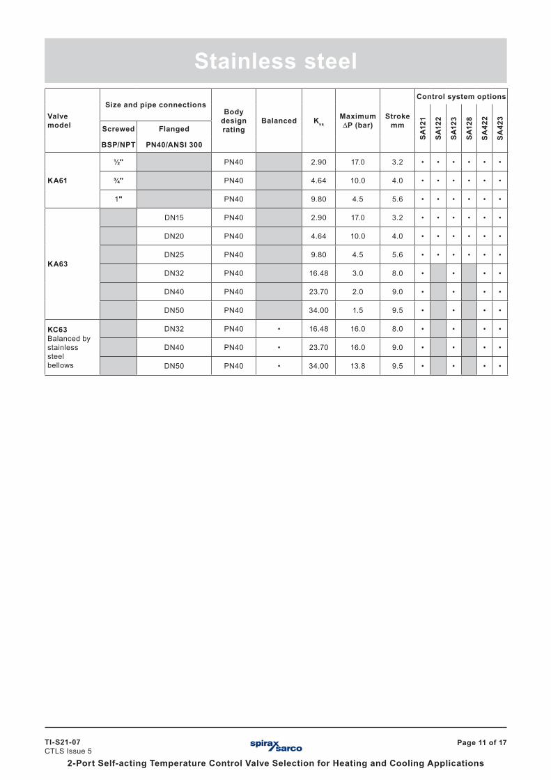
KA61
½" PN40 2.90 17.0 3.2 • • • • • •
¾" PN40 4.64 10.0 4.0 • • • • • •
1" PN40 9.80 4.5 5.6 • • • • • •
KA63
DN15 PN40 2.90 17.0 3.2 • • • • • •
DN20 PN40 4.64 10.0 4.0 • • • • • •
DN25 PN40 9.80 4.5 5.6 • • • • • •
DN32 PN40 16.48 3.0 8.0 • • • •
DN40 PN40 23.70 2.0 9.0 • • • •
DN50 PN40 34.00 1.5 9.5 • • • •
KC63Balanced by stainless steel bellows
DN32 PN40 • 16.48 16.0 8.0 • • • •
DN40 PN40 • 23.70 16.0 9.0 • • • •
DN50 PN40 • 34.00 13.8 9.5 • • • •
Stainless steel

TI-S21-07 CTLS Issue 5
Page 12 of 17
2-Port Self-acting Temperature Control Valve Selection for Heating and Cooling Applications
Gunmetal
Valve selection dataTable 6 Normally closed valves for cooling applicationsFor pressure temperature relationships please refer to the pressure/temperature charts in Table 4, page 6.
Valve model
Size and pipe connections Control system options
ScrewedBSP/NPT
FlangedPN25/ANSI 150
Body design rating
Balanced Kvs Maximum P (bar)
Stroke mm
SA12
1
SA12
2
SA12
3
SA12
8
SA42
2
SA42
3
BMF2 ½" PN25 0.59 10.3 3.2 • • • • • •
SBRA Optional bleed available
½" PN25 2.58 12.0 3.2 • • • • • •
¾" PN25 3.86 7.0 4.0 • • • • • •
1" PN25 6.80 4.7 5.0 • • • • • •
NRSA Double seated valve
2½" DN65 PN25 65.00 2.7 9.5 • • • •
3" DN80 PN25 94.00 2.0 9.5 • • • •
KX51 Optional bleed available
1" PN25 9.80 3.5 5.6 • • • • • •
1¼" PN25 16.48 2.3 8.0 • • • •
1½" PN25 23.70 1.7 9.0 • • • •
2" PN25 34.00 1.1 9.5 • • • •
KY51* Balanced by phosphor bronze bellows. Optional bleed available
1¼" PN25 • 16.48 9.0 8.0 • • • •
1½" PN25 • 23.70 8.2 9.0 • • • •
2" PN25 • 34.00 6.9 9.5 • • • •

Page 13 of 17
2-Port Self-acting Temperature Control Valve Selection for Heating and Cooling Applications
TI-S21-07 CTLS Issue 5
Cast iron
Valve model
Size and pipe connections Control system options
ScrewedBSP/NPT
FlangedPN16
Body design rating
Balanced Kvs Maximum P (bar)
Stroke mm
SA12
1
SA12
2
SA12
3
SA12
8
SA42
2
SA42
3
BMFRA ½" PN16 0.59 10.3 3.2 • • • • • •
KX31 Screwed and KX33 flanged.Optional bleed available
½" DN15 PN16 2.90 12.0 3.2 • • • • • •
¾" DN20 PN16 4.64 7.0 4.0 • • • • • •
1" DN25 PN16 9.80 3.5 5.6 • • • • • •
1¼" DN32 PN16 16.48 2.3 8.0 • • • • • •
1½" DN40 PN16 23.70 1.7 9.0 • • • • • •
2" DN50 PN16 34.00 1.1 9.5 • • • • • •
KY31* Screwed and KY33* flanged by phosphor bronze bellows. Optional bleed available
1¼" PN16 • 16.48 9.0 8.0 • • • •
1½" PN16 • 23.70 8.2 9.0 • • • •
2" DN16 • 34.00 6.9 9.5 • • • •
* Please note: The KY31, KY33, and KY51 can also be used on water applications where high P conditions exist.

TI-S21-07 CTLS Issue 5
Page 14 of 17
2-Port Self-acting Temperature Control Valve Selection for Heating and Cooling Applications
Cast carbon steel
SBRA (DN15 - DN25 screwed)
KX31 (DN15 - DN25 screwed)KX33 (DN15 - DN25 flanged)KX51 (DN25 screwed)
KX31 (DN32 - DN50 screwed)KX33 (DN32 - DN50 flanged)KX43 (DN15 - DN50 flanged)KX51 (DN32 - DN50 screwed)
NSRA (DN65 - DN80 screwed)NSRA (DN65 - DN80 flanged)
KY51 (DN32 - DN50 screwed)KY31 (DN32 - DN50 screwed)KY33 (DN32 - DN50 screwed)KY43 (DN32 - DN50 flanged)
BXRA (DN15 screwed)BMFRA (DN15 flanged)BMRA (DN15 flanged)
Valve model
Size and pipe connections Control system options
Flanged Body design rating Balanced Kvs
Maximum P (bar)
Stroke mm SA
121
SA12
2
SA12
3
SA12
8
SA42
2
SA42
3
PN25 PN40
BMRA DN15 PN25 0.59 10.3 3.2 • • • • • •
KX43Optional bleed available
DN15 PN40 2.90 12.0 3.2 • • • • • •
DN20 PN40 4.64 7.0 4.0 • • • • • •
DN25 PN40 9.80 3.5 5.6 • • • • • •
DN32 PN40 16.48 2.3 8.0 • • • •
DN20 PN40 23.70 1.7 9.0 • • • •
DN50 PN40 34.00 1.1 9.5 • • • •
KY43Balanced by phosphor bronze bellows. Optional bleed available.
DN32 PN40 • 16.48 9.0 8.0 • • • •
DN40 PN40 • 23.70 8.2 9.0 • • • •
DN50 PN40 • 34.00 6.9 9.5 • • • •

Page 15 of 17
2-Port Self-acting Temperature Control Valve Selection for Heating and Cooling Applications
TI-S21-07 CTLS Issue 5
Table 7 Control system selectionThe control systems are available in four configurations as shown below. Each type is available with either a dial or knob type temperature adjustment except the Type 422 (dial only). Dimensions are approximate in mm
ActuatorSA121, SA128
271
Setting knob185
310 (SA121)178 (SA128)
Sensor
Capillary
25
ActuatorSA122
415
Setting knob
240
SensorCapillary
17
Actuator
Type 422
395
Setting dial
326
Sensor
Capillary25
ActuatorSA123, SA423
271
Setting knob
248
Sensor
Capillary25
270
Capillary
Specifications
Type Range Temperature Maximum sensor temperature Material Weightkg
Standard capillary tube (m)
SA121
1 - 15 to 50 °C
55 °C over set value to max. 190 °C Brass 2.0 2, 4, 8 and 202 40 to 105 °C
3 95 to 160 °C
SA1221 - 20 to 120 °C
55 °C over set value Brass 1.8 2, 4, 8 and 202 40 to 170 °C
SA123
1 - 15 to 50 °C
55 °C over set value Brass 2.5 2, 4, 8 and 202 40 to 150 °C
3 95 to 160 °C
SA1281 - 20 to 120 °C
55 °C over set value to max. 190 °C Brass 1.8 2, 4, 8 and 202 40 to 170 °C
SA4221 - 20 to 120 °C
55 °C over set value Stainless steel 1.4 2.4 or 4.8*2 40 to 170 °C
SA423
1 - 15 to 50 °C
55 °C over set valueStainless steel
sensor remainder brass
2.5 2, 4, 8 and 202 40 to 150 °C
3 95 to 160 °C
* Longer lengths up to 9.6 m are available to special order

TI-S21-07 CTLS Issue 5
Page 16 of 17
2-Port Self-acting Temperature Control Valve Selection for Heating and Cooling Applications
Table 8 Control system ancillaries
Mounting options and ancillariesControl system type
SA121 SA122 SA123 SA128 SA422 SA423
Standard pocket immersion length (mm) 315 258 258 258 180 326
Size (BSP or NPT) 1" ¾" 1" 1" 1" 1"
Wall mounting bracket • • • •
Union kit for sensor immersion without pocket • • • • • •
Mild steel pocket longer pocket option
• • • •* • •
Stainless steel pocket longer pocket option
• • • • •* • • •
Copper pocket longer pocket option
• • • •* • •
Brass pocket longer pocket option
• • • •* • •
Glass pocket with bracket and rubber bung • • •
Duct fixing kit • • •
Twin sensor adaptorWhen coupled to a valve allows operation by two actuators
• • • • • •
* Special long pockets are available in lengths from 0.5 m to 1 m.
Twin sensor adaptor
Manualactuator
1"
1"
¾"
¾"
1" shown
Twin sensor adaptor

Page 17 of 17
2-Port Self-acting Temperature Control Valve Selection for Heating and Cooling Applications
TI-S21-07 CTLS Issue 5
Table 8 Control system ancillaries (continued)
Mounting options and ancillariesControl system type
SA121 SA122 SA123 SA128 SA422 SA423
Manual actuatorWhen coupled to a valve, it enables the valve to be manually operated.
• • • • • •
Manualactuator
Manualactuator