2-Port Gateway User’s...
89
2-Port Gateway User’s Guide
Transcript of 2-Port Gateway User’s...

2-Port Gateway User’s Guide

2-Port Gateway User’s Guide
All Rights Reserved
Copyright © 2002, Net2Phone, Inc. All rights reserved. The use, disclosure, modification, transfer, or transmittal of this
work for any purpose, in any form, or by any means, without the written permission of Net2Phone, is strictly forbidden.
2-Port Gateway User’s Guide Rev. 1.0 December 2002
Disclaimer The content of this manual is subject to change without notice and should not be construed as a commitment by the distributor or Net2Phone. This manual is furnished for inform ational use only and Net2Phone assumes no responsibility for any errors or inaccuracies that may appear herein. Any Net2Phone services provided through this equipment are not intended to replace or be a substitute for primary line voice services or Plain Old Telephone Service (“POTS”) and are not meant to provide guaranteed Automatic Number Identification or Automatic Location Information capabilities associated with 911 or E911 services or to permit access to 411 directory assistance services. Net2Phone will not be liable for any damages, expenses, liabilities, risks, or harms arising out of or related to the Net2Phone services provided through this equipment.

2-Port Gateway User’s Guide
i
Table Of Contents 1. WELCOME........................................................ 1
OVERVIEW.............................................................1 PRODUCT FEATURES ...............................................2 2-PORT GATEWAY HARDWARE OVERVIEW ..................3
2-Port Gateway Front Panel ...............................3 2-Port Gateway Back Panel................................5
2. GETTING STARTED......................................... 7
OVERVIEW.............................................................7 HARDWARE REQUIREMENTS .....................................7 SETTING UP YOUR 2-PORT GATEWAY........................8
Obtaining an IP Address for Your PC ................12
3. CONFIGURING YOUR 2-PORT GATEWAY .. 15
OVERVIEW...........................................................15 WAN CONFIGURATION ..........................................16
Using DHCP Addressing ..................................16 Using Static IP Addressing ...............................17 Setting up Point -to-Point Protocol over Ethernet
(PPPoE).................................................20 OPTIONAL: LAN CONFIGURATION ...........................22
Using DHCP Addressing ..................................22 Using Static IP Addressing ...............................24
NET2PHONE ACCOUNT CONFIGURATION ..................26 CONNECTING TO THE INTERNET ..............................28
4. USING THE WEB MANAGEMENT TOOL..... 31
LOGGING INTO THE 2-PORT GATEWAY .....................31 NAVIGATING THE W EB MANAGEMENT TOOL ..............33 MAIN MENU ITEMS ................................................34 CONFIGURE GATEWAY FOLDER...............................35
2-Port Gateway User’s Guide
ii
WAN Configuration Page .................................36 LAN Configuration Page...................................39 Net2Phone Configuration Page ........................42 Configuring Firewall Ports ................................44 User Configuration Page ..................................47
CONFIGURE ADVANCED SETTINGS FOLDER...............48 Telephony Configuration Page..........................49 SNMP Trap Configuration Page........................50 Local Server Configuration Page ......................51
MONITOR GATEWAY FOLDER..................................53 Ethernet Statistics............................................54 DSP Statistics .................................................57 Tcid Configuration............................................59
DEVICE INFORMATION PAGE ...................................63 UPDATE F IRMWARE PAGE ......................................65 SAVE CHANGES PAGE ...........................................65 RESET PAGE........................................................67 RESTART GATEWAY PAGE .....................................67
5. PLACING AND RECEIVING CALLS.............. 69
OVERVIEW...........................................................69 CALLING REGULAR TELEPHONES .............................69
Calls within North America................................69 International calls.............................................70
CALLING OTHER NET2PHONE DEVICES ....................72 Calling another Net2Phone Device ...................72
RECEIVING A CALL FROM ANOTHER NET2PHONE DEVICE ...............................................................72 THE PSTN LIFE LINE ............................................73
APPENDICES....................................................... 75
APPENDIX A – TROUBLESHOOTING ..........................75 Common mechanical installation problems ........75

2-Port Gateway User’s Guide
iii
Common network connection problems.............76 Common configuration problems ......................77 Common Internet connectivity problems ............77 Problems using the 2-Port Gateway..................78
APPENDIX B – TECHNICAL SUPPORT .......................79 APPENDIX C – SYSTEM SPECIFICATIONS ..................80 APPENDIX D – APPROVALS AND LISTINGS.................82

2-Port Gateway User’s Guide
1
1. Welcome Overview
Congratulations on purchasing the 2-Port Gateway!
The 2-Port Gateway is a LAN router and Voice over Internet Protocol (VoIP) broadband device that allows you to connect two analog phones for simultaneous outgoing calls over the Internet using a single Ethernet Local Area Network (LAN) connection. The 2-Port Gateway converts the analog signal from your telephone(s) to Voice over Internet Protocol (VoIP). It then uses the LAN’s broadband connection to send calls over the Internet via Net2Phone’s service platform. Since Net2Phone calls bypass most of the Public Switched Telephone Network (PSTN), the result is significant savings on long-distance communications services.
The 2-Port Gateway’s broadband router functionality enables you to share a high-speed Internet connection such as DSL/cable for use with multiple
computers/IP devices.
The 2-Port Gateway features several proprietary Quality of Service (QoS) enhancements, including:
?? G.168 echo cancellation ?? Voice Activity Detection (VAD) ?? Comfort Noise Generation (CNG) ?? Dynamic jitter buffer control

2-Port Gateway User’s Guide
2
Product Features
Designed for versatility and performance, the 2-Port Gateway provides the following features:
?? One 10/100 Mbps WAN port for connecting a call agent
?? One 10/100 Mbps LAN port for connecting
to a local network
?? One analog POTS (Plain Old Telephone System) interface for a PSTN “Life Line”
?? Two phone ports to allow two analog phone connections for simultaneous outgoing calls
?? Silence Suppression to reduce bandwidth
consumption
?? Dynamic Host Configuration Protocol (DHCP) or Static IP address assignment
?? Comfort Noise generation for more natural experience
?? Adaptive jitter buffer for smooth voice quality
?? Remote software downloading/updating
?? Supports all normal phone features including call waiting, call forwarding, and Caller ID
?? PSTN switchover in case of a power failure or network breakdown
?? Intelligent dialing mode from IP/PSTN call alteration via configurable hot key (# key is the default)
2-Port Gateway User’s Guide
3
?? Actively listens for incoming calls from the PSTN and rings on connected phones when a call comes in on the PSTN Life Line port
?? Users can utilize the same phone for PSTN and Internet phone calls; an incoming call on the Life Line port will ring on the phone
connected to the 2-Port Gateway
2-Port Gateway Hardware Overview
The following graphics detail the front and back panels of the 2-Port Gateway.
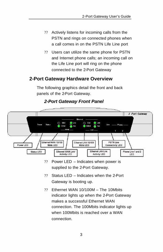
2-Port Gateway Front Panel
?? Power LED – Indicates when power is supplied to the 2-Port Gateway.
?? Status LED – Indicates when the 2-Port
Gateway is booting up.
?? Ethernet WAN 10/100M – The 10Mbits indicator lights up when the 2-Port Gateway makes a successful Ethernet WAN connection. The 100Mbits indicator lights up when 100Mbits is reached over a WAN
connection.
2-Port Gateway User’s Guide
4
?? Ethernet WAN Link/Activity LED – If the LED is continuously illuminated, the connection made through the corresponding port is successfully running in full duplex mode. If the LED is flickering, it means the connection is experiencing collisions. Infrequent collisions are normal. If this LED is flickering too often, there may be a problem with your connection. Check Appendix A, Troubleshooting if you think
there’s a problem.
?? Ethernet LAN 10/100M – The 10Mbits indicator lights up when the 2-Port Gateway makes a successful Ethernet LAN connection. The 100Mbits indicator lights up when 100Mbits is reached over a LAN
connection.
?? Ethernet LAN Link/Activity LED – If the LED is continuously illuminated, the connection made through the corresponding port is successfully running in full Duplex mode. If the LED is flickering, it means the connection is experiencing collisions. Infrequent collisions are normal. If this LED is flickering too often, there may be a problem with your connection. Check Appendix A, Troubleshooting if you think
there’s a problem.
?? Line LED – Indicates when the PSTN Life-Line is in use.
2-Port Gateway User’s Guide
5
?? Phone 1 and 2 LED – Indicates when either
or both of the phone ports are in use.
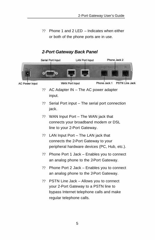
2-Port Gateway Back Panel
?? AC Adapter IN – The AC power adapter
input.
?? Serial Port input – The serial port connection jack.
?? WAN Input Port – The WAN jack that connects your broadband modem or DSL line to your 2-Port Gateway.
?? LAN Input Port – The LAN jack that connects the 2-Port Gateway to your peripheral hardware devices (PC, Hub, etc.).
?? Phone Port 1 Jack – Enables you to connect
an analog phone to the 2-Port Gateway.
?? Phone Port 2 Jack – Enables you to connect an analog phone to the 2-Port Gateway.
?? PSTN Line Jack – Allows you to connect your 2-Port Gateway to a PSTN line to bypass Internet telephone calls and make
regular telephone calls.

2-Port Gateway User’s Guide
6
2-Port Gateway User’s Guide
7
2. Getting Started Overview
The Getting Started section details the hardware requirements for proper installation of the 2-Port Gateway, as well as instructions for connecting the 2-Port Gateway to your broadband connection, your PC, and your phone lines. This section also describes how to obtain an IP address, if needed, for
use in configuring the 2-Port Gateway.
Hardware Requirements
To use the 2-Port Gateway, you will need:
?? One A/C power adapter (included)
?? A broadband Internet connection, such as a DSL or cable modem, a T1 line, etc.
?? One Net2Phone multi-user account number and PIN on each port, or one single-use Net2Phone account per port (available from
your distributor)
?? A PC workstation with any recent Web browser, connected to the LAN port to
configure the device
?? If your WAN uses static IP addresses, you will also need: an IP address, Netmask, and gateway address for the 2-Port Gateway (all available from your broadband service
provider)
2-Port Gateway User’s Guide
8
Setting Up Your 2 -Port Gateway
Your 2-Port Gateway can be used as a router to connect up to 253 additional devices (such as PCs or hubs) to create a LAN environment, as well as a VoIP device allowing you to connect two analog telephones to place inexpensive calls over the
Internet.
While one of the primary functions of the 2-Port Gateway is as a router, you can choose to use it as a VoIP device only. This chapter describes how to set up the 2-Port Gateway to perform both functions.
You will perform the following basic, high-level steps, which are outlined in more detail starting on page 10:
1. Install the 2-Port Gateway in its location and
connect the cabling.
2. Connect your PC to the 2-Port Gateway.
3. Reboot your PC and verify that the 2-Port
Gateway is accessible.
4. Log into the 2-Port Gateway’s Web Management Tool to configure your WAN and LAN settings as necessary (i.e., change Point-to-Point Protocol over Ethernet (PPPoE) and Static/DHCP settings, if
necessary).
5. Input your Net2Phone account(s) via the Web Management Tool.
6. Reboot the 2-Port Gateway.
2-Port Gateway User’s Guide
9
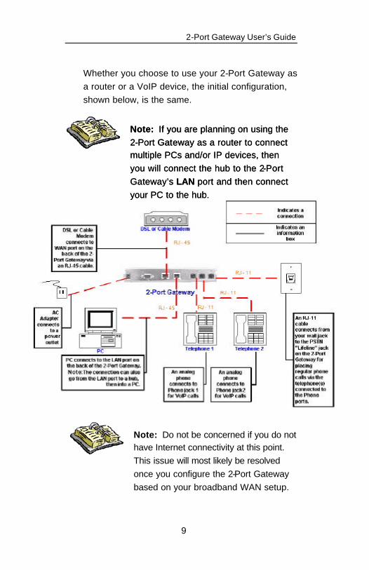
Whether you choose to use your 2-Port Gateway as a router or a VoIP device, the initial configuration, shown below, is the same.
Note: Do not be concerned if you do not have Internet connectivity at this point. This issue will most likely be resolved once you configure the 2-Port Gateway based on your broadband WAN setup.
Note: If you are planning on using the 2-Port Gateway as a router to connect multiple PCs and/or IP devices, then you will connect the hub to the 2-Port Gateway’s LAN port and then connect your PC to the hub.
Note: If you are planning on using the 2-Port Gateway as a router to connect multiple PCs and/or IP devices, then you will connect the hub to the 2-Port Gateway’s LAN port and then connect your PC to the hub.

2-Port Gateway User’s Guide
10
To set up the 2-Port Gateway:
1. Connect the WAN port on the back of the 2-Port Gateway (shown in the figure on the next page) to your broadband/DSL/cable modem or existing LAN broadband connection (i.e., office network) via an RJ-45
cable.
2. Connect the LAN port on the 2-Port Gateway to your computer or a hub that
routes to your PC via an RJ-45 cable.
Note: If you connect a hub to the LAN port, then you must connect your
PC to the hub.

2-Port Gateway User’s Guide
11
3. Connect your phone(s) to the Phone 1 jack (and Phone 2 jack if you are using two phones).
4. Optional: To set up the ability to place calls using your regular telephone line (PSTN) in case of power outages or if your broadband service provider is down, connect an analog phone line (via an RJ-11 cable) to the Line jack in the back panel of the device. For more information on placing and receiving regular (PSTN) calls on the 2-Port Gateway, see Section 5, Placing and Receiving Calls.
5. Connect the AC Adapter cord to the back of the 2-Port Gateway and plug in the power cord. Your cable connections should now
resemble the diagram on page 9.
6. Reboot your PC after all the cables have been installed in order to obtain an IP
address from the 2-Port Gateway.
7. Once your PC has rebooted, you should be able to connect to the 2-Port Gateway’s Web Management Tool by entering the following address into your PC’s Web
browser: http://192.168.100.1
Note: Do not be concerned if you do not have Internet connectivity at this point. This issue will most likely be resolved once you configure the 2-Port Gateway based on your broadband WAN setup.
2-Port Gateway User’s Guide
12
If you are able to connect to 198.162.100.1 via a Web browser from your PC, then you are ready to configure the 2-Port Gateway. Please proceed to
Section 3, Configuring Your 2-Port Gateway.
If you cannot connect to 192.168.100.1, then you need to verify that all of your cabling is properly connected. If all of the connections are secure, then you need to obtain an IP address for your PC using MS-DOS (see below).
Obtaining an IP Address for Your PC
After rebooting your PC, if you are unable to connect to the Web Management Tool from your PC, you can manually direct your PC to connect
to the 2-Port Gateway to obtain an IP address.
To manually obtain an IP address:
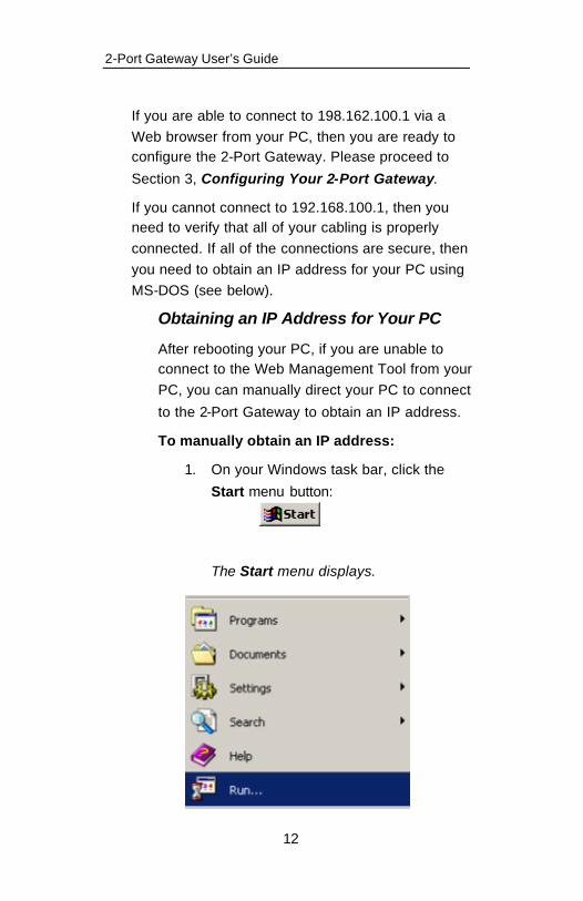
1. On your Windows task bar, click the
Start menu button:
The Start menu displays.

2-Port Gateway User’s Guide
13
2. Click Run to access the Run window:
The Run window opens.
3. Type COMMAND in the Open field and click the OK button.
The DOS prompt window displays.
Note: If COMMAND does not work, try
typing CMD.
4. From the DOS C:\> prompt, type:
ipconfig /renew
(Remember to include the space between “ipconfig” and the “/”).
2-Port Gateway User’s Guide
14
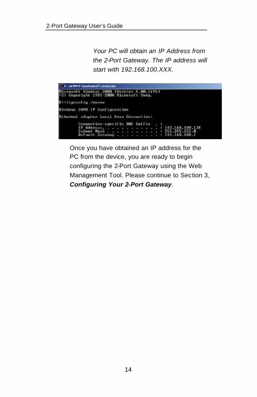
Your PC will obtain an IP Address from the 2-Port Gateway. The IP address will start with 192.168.100.XXX.
Once you have obtained an IP address for the PC from the device, you are ready to begin configuring the 2-Port Gateway using the Web Management Tool. Please continue to Section 3, Configuring Your 2-Port Gateway.
2-Port Gateway User’s Guide
15
3. Configuring Your 2-Port Gateway
Overview
This section describes the basic configuration setups for your 2-Port Gateway, including:
?? WAN
?? LAN
?? Net2Phone Account
All configurations are accomplished via the Web Management Tool, which is accessible using the Web browser on your PC. (Your PC must be connected to the LAN port of the 2-Port Gateway or a hub connected to that same port, and your PC must have been rebooted.) For complete details on the Web Management Tool, see Section 4, Using the Web Management Tool.
Reminder: If you cannot access the Web Management Tool via your PC’s Web browser, you need to manually renew your IP address from a DOS prompt. For more information, see Obtaining an IP Address for Your PC
in Section 2.
2-Port Gateway User’s Guide
16
Note: Do not be concerned if you do not have Internet connectivity at this point. This issue will most likely be resolved once you configure the 2-Port Gateway based on your broadband WAN setup.
WAN Configuration
Using DHCP Addressing
The 2-Port Gateway’s default WAN configuration utilizes DHCP (Dynamic Host Configuration Protocol) for obtaining IP address parameters. If your WAN is using DHCP, the 2-Port Gateway’s IP address parameters were configured automatically when you connected it to your broadband service connection (corporate WAN,
cable/DSL modem, or router).
Note: If your broadband service provider uses PPPoE, please refer to Setting up Point -to-Point Protocol over Ethernet (PPPoE) on pages 23 and 24 in this section to configure
PPPoE settings.
If your WAN uses static IP addressing, please refer to Using Static IP Addressing on the next
page.
2-Port Gateway User’s Guide
17
Using Static IP Addressing
This section explains how to connect your 2-Port Gateway to a broadband service provider that utilizes Static IP assigned addresses instead of
DHCP.
If your WAN uses static IP addressing, then you must disable the 2-Port Gateway’s default DHCP setting and then enter your static IP address parameters.
To disable DHCP and enter static IP address
parameters:
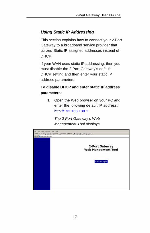
1. Open the Web browser on your PC and enter the following default IP address:
http://192.168.100.1
The 2-Port Gateway’s Web Management Tool displays.

2-Port Gateway User’s Guide
18
2. Click the Click to Login button on the opening page. The Network Password dialog box
appears.
3. Enter your user name and password in the text boxes provided, and click the
Enter button.
NOTE: The default user name is admin and the default password is n2p. Remember that both the user name and password are case sensitive.
You are now logged into the Web Management Tool. The left frame displays the Tool menu. The right frame displays the Device Information page.
4. Click the Configure Gateway Settings menu folder in the left sidebar menu to
display sub menu items.
2-Port Gateway User’s Guide
19
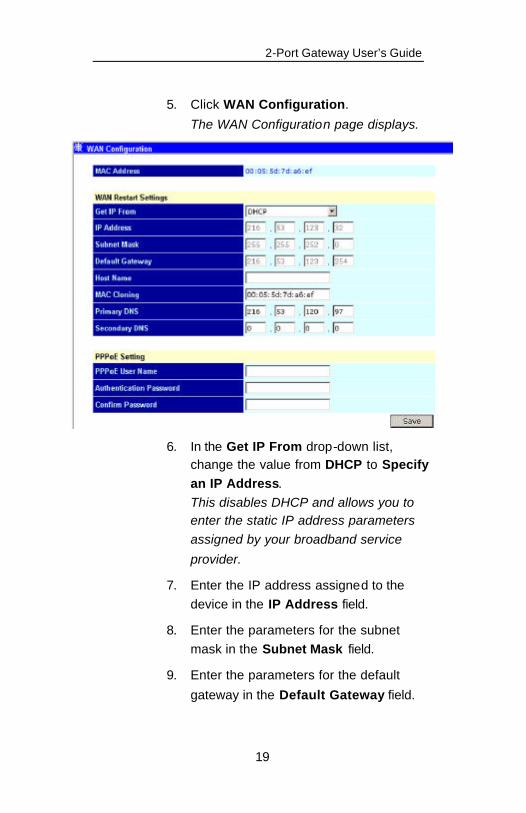
5. Click WAN Configuration.
The WAN Configuration page displays.
6. In the Get IP From drop-down list, change the value from DHCP to Specify an IP Address. This disables DHCP and allows you to enter the static IP address parameters assigned by your broadband service
provider.
7. Enter the IP address assigned to the device in the IP Address field.
8. Enter the parameters for the subnet mask in the Subnet Mask field.
9. Enter the parameters for the default
gateway in the Default Gateway field.
2-Port Gateway User’s Guide
20
10. Click the Save button.
11. The 2-Port Gateway should prompt you to reboot the device. If not, reboot the 2-Port Gateway by unplugging the power cord from the back of the 2-Port Gateway, waiting three seconds, and
plugging the power cord back in.
Setting up Point-to-Point Protocol over Ethernet (PPPoE)
PPPoE is a specification for connecting users on a broadband connection to the Internet through a common broadband medium, such as a single
DSL line, wireless connection, or cable modem.
Some broadband service providers use PPPoE to establish communications with an end-user. Check with your broadband service provider to see if they use PPPoE. If they do, you will have to enable PPPoE via the 2-Port Gateway’s Web
Management Tool page.
To enable PPPoE:
1. Log in to the 2-Port Gateway’s Web Management Tool using the following IP
address: http://192.168.100.1 .
2. Click the Configure Settings menu folder (if not open).
3. Click WAN Configuration.
4. At the bottom of the WAN Configuration page, enter your PPPoE User Name.
5. Enter your PPPoE Password.
2-Port Gateway User’s Guide
21
6. Confirm your PPPoE Password.
7. Click the Save button to save your PPPoE settings.
8. The 2-Port Gateway should prompt you to reboot the device. If not, reboot the 2-Port Gateway by unplugging the power cord from the back of the 2-Port Gateway, waiting three seconds, and plugging the power cord back in.
9. Log back in to the Web Management
Tool.
10. Click WAN Configuration.
11. At the bottom of the WAN Configuration page, click the Connect button to connect to the PPPoE server.
Note: If you are switching from PPPoE to DHCP or Static IP, you must disable PPPoE from the WAN Configuration page by removing the user name and password and then save the changes. Then go back into the WAN Configuration page and enable DHCP or enter a static IP and save the changes.
2-Port Gateway User’s Guide
22
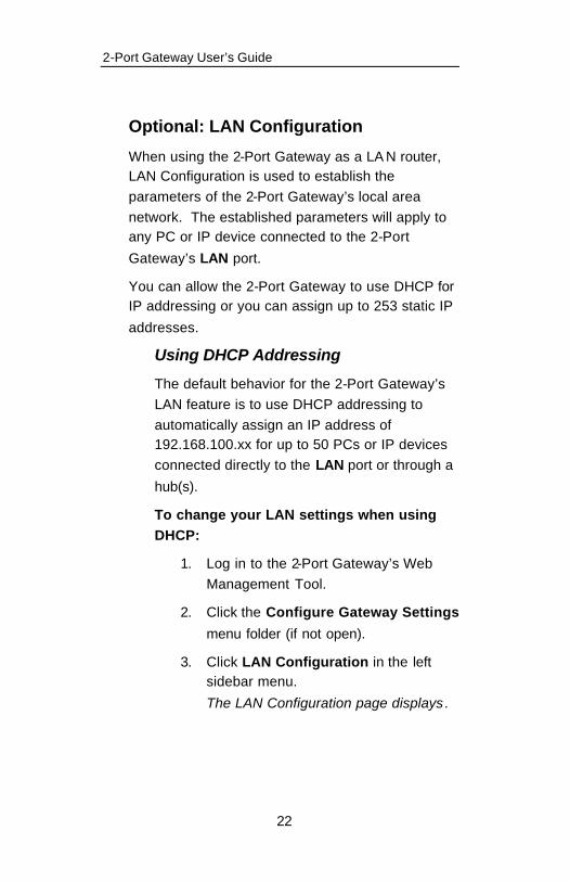
Optional: LAN Configuration
When using the 2-Port Gateway as a LA N router, LAN Configuration is used to establish the parameters of the 2-Port Gateway’s local area network. The established parameters will apply to any PC or IP device connected to the 2-Port
Gateway’s LAN port.
You can allow the 2-Port Gateway to use DHCP for IP addressing or you can assign up to 253 static IP
addresses.
Using DHCP Addressing
The default behavior for the 2-Port Gateway’s LAN feature is to use DHCP addressing to automatically assign an IP address of 192.168.100.xx for up to 50 PCs or IP devices connected directly to the LAN port or through a
hub(s).
To change your LAN settings when using DHCP:
1. Log in to the 2-Port Gateway’s Web Management Tool.
2. Click the Configure Gateway Settings
menu folder (if not open).
3. Click LAN Configuration in the left sidebar menu.
The LAN Configuration page displays.
2-Port Gateway User’s Guide
23
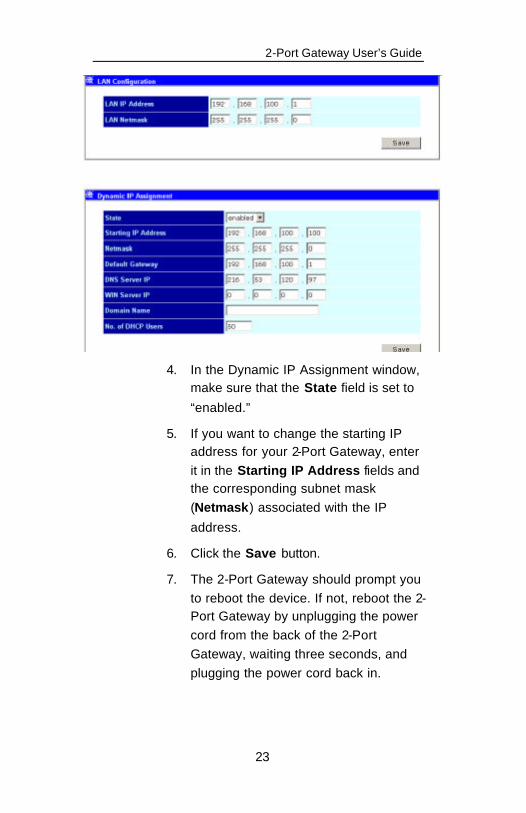
4. In the Dynamic IP Assignment window, make sure that the State field is set to
“enabled.”
5. If you want to change the starting IP address for your 2-Port Gateway, enter it in the Starting IP Address fields and the corresponding subnet mask (Netmask) associated with the IP
address.
6. Click the Save button.
7. The 2-Port Gateway should prompt you to reboot the device. If not, reboot the 2-Port Gateway by unplugging the power cord from the back of the 2-Port Gateway, waiting three seconds, and plugging the power cord back in.

2-Port Gateway User’s Guide
24
Using Static IP Addressing
You can use static IP addresses on the PCs and/or IP devices connected to the 2-Port Gateway. The 2-Port Gateway can assign up to 253 static IP addresses to PCs/devices connected to the 2-Port Gateway.
To change your LAN settings when using
static IP addressing:
1. Log in to the 2-Port Gateway’s Web Management Tool.
2. Click the Configure Gateway Settings menu folder (if not open).
3. Click LAN Configuration in the left sidebar menu. The LAN Configuration page displays.
2-Port Gateway User’s Guide
25
4. In the Dynamic IP Assignment window, select disabled in the State field’s drop-
down list.
5. Click the Save button.
6. The 2-Port Gateway should prompt you to reboot the device. If not, reboot the 2-Port Gateway by unplugging the power cord from the back of the 2-Port Gateway, waiting three seconds, and
plugging the power cord back in.
7. For each PC and/or IP device connected to the 2-Port Gateway’s LAN, enter the 2-Port Gateway’s Gateway, Subnet Mask and DNS Server entries in
those particular PCs and/or IP devices.

2-Port Gateway User’s Guide
26
Net2Phone Account Configuration
To place Internet calls, you must enter at least one Net2Phone account number and PIN. You can enter the same Net2Phone account number and PIN for both phone ports, if you want both ports to share the same multi-use account. You can also use two separate accounts in the 2-Port Gateway, one saved to port 1, and the other saved to port 2. If you do not have a Net2Phone account number and PIN, please
contact your local distributor.
2-Port Gateway User’s Guide
27
To set your Net2Phone account number and PIN:
1. Log in to the 2-Port Gateway’s Web Management Tool.
2. Click the Configure Gateway Settings menu folder (if not open).
3. Click Net2Phone Configuration in the left sidebar menu. The Net2Phone Configuration page displays.
4. Enter your account number in the Account
1 field.
5. Enter your PIN in the PIN field.
6. If you have a second account number, enter
it in the Account 2 field.
7. Enter the PIN for the second account in the PIN field.
8. If you expect to receive incoming calls from other Net2Phone devices and you are using two separate accounts, you can click the Enable Incoming Call checkbox for each port. If both ports are using the same multi-use account, only one port can be set to receive incoming calls.
For information on making a device-to-device call, please refer to Section
5, Placing and Receiving Calls.
2-Port Gateway User’s Guide
28
9. Click the Save button to save the changes
made to the Net2Phone Configuration page.
10. The 2-Port Gateway should prompt you to reboot the device. If not, reboot the 2-Port Gateway by unplugging the power cord from the back of the 2-Port Gateway, waiting three seconds, and plugging the power cord
back in.
Connecting to the Internet
Once your WAN configuration has been set and the 2-Port Gateway has been rebooted, your 2-Port Gateway, your PC, and any other connected devices
should have Internet connectivity.
If you do not have Internet connectivity, try the following:
1. Verify that all cables are connected properly.
2. Verify that all WAN settings are correct.
3. Verify that your PC is getting an IP address from the 2-Port Gateway by:
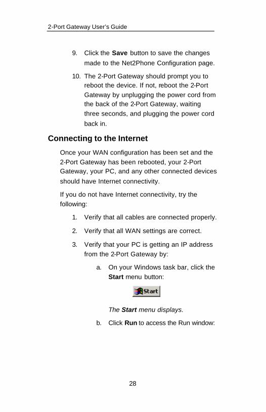
a. On your Windows task bar, click the Start menu button:
The Start menu displays.
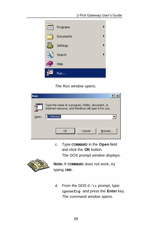
b. Click Run to access the Run window:
2-Port Gateway User’s Guide
29
The Run window opens.
c. Type COMMAND in the Open field and click the OK button.
The DOS prompt window displays.
d. From the DOS C:\> prompt, type: ipconfig and press the Enter key. The command window opens.
Note: If COMMAND does not work, try
typing CMD.

2-Port Gateway User’s Guide
30
e. The IP address displayed should be
192.168.100.xx.
4. Try rebooting the DSL/cable modem to which the 2-Port Gateway is connected to
reset the IP address for the 2-Port Gateway.
5. Contact your network administrator or broadband service provider.
2-Port Gateway User’s Guide
31
4. Using the Web Management Tool
To configure the 2-Port Gateway’s various parameters, you must use the Web Management Tool. The Web Management Tool allows you to customize the 2-Port Gateway by changing specific parameters within the menu items.
This section outlines how to log in to the 2-Port Gateway and describes all fields available on every configuration page in the Web Management Tool. Each configuration page is accessible by logging into the 2-Port Gateway from your PC’s Web browser, and clicking the link on the left-hand side
menu.
Logging into the 2-Port Gateway
To access each configuration menu, you need to log into the 2-Port Gateway.
To log into the 2-Port Gateway:
1. Open the Web browser on your PC and enter the following default IP address:
http://192.168.100.1.
The 2-Port Gateway’s Web Management Tool displays.
2-Port Gateway User’s Guide
32
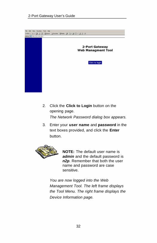
2. Click the Click to Login button on the opening page.
The Network Password dialog box appears.
3. Enter your user name and password in the text boxes provided, and click the Enter
button.
NOTE: The default user name is admin and the default password is n2p. Remember that both the user name and password are case sensitive.
You are now logged into the Web Management Tool. The left frame displays the Tool Menu. The right frame displays the
Device Information page.
2-Port Gateway User’s Guide
33
Navigating the Web Management Tool
Once you have logged into the 2-Port Gateway, you can navigate through the Web Management Tool by using the menu in the left frame of the Web page. To access a specific configuration page, click on a menu folder, which displays a list of configuration menu items. Then click on the specific configuration item.
For example, click the Configure Gateway Settings folder in the left frame of the page. The following four items are listed under the folder:
?? WAN Configuration
?? LAN Configuration
?? Net2Phone Configuration
?? User Configuration
To access the WAN Configuration page, simply click the WAN Configuration link in the left frame.

2-Port Gateway User’s Guide
34
Main Menu Items
The 2-Port Gateway’s Web Management Tool contains the following folders and configuration
pages:
?? Configure Gateway Settings – Allows you to configure the 2-Port Gateway’s WAN,
LAN, and Net2Phone account settings
?? Configure Advanced Settings – Allows you to configure telephone settings and local
server settings
?? Monitor Gateway – Displays various statistics pages
?? Device Configuration – Allows you to change general device configuration settings
?? Update Firmware – Connects to an upgrade server for updating your 2-Port Gateway’s firmware
?? Save Changes – Saves the changes you made to the settings on your 2-Port Gateway
?? Reset – Resets the factory default settings
of the 2-Port Gateway
?? Restart – Restarts your 2-Port Gateway

2-Port Gateway User’s Guide
35
Configure Gateway Folder
The Configure Gateway folder contains four pages:
?? WAN Configuration – Allows you to configure WAN IP addresses and PPPoE
?? LAN Configuration – Allows you to configure your LAN and Gateway IP address
and LAN settings
?? Net2Phone Configuration – Allows you to configure your Net2Phone account number and PIN, firewall port settings, and call
server addresses on the 2-Port Gateway
?? User Configuration – Allows you to configure your Login password
2-Port Gateway User’s Guide
36
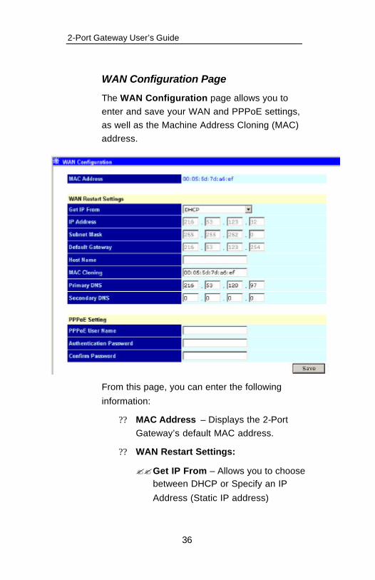
WAN Configuration Page
The WAN Configuration page allows you to enter and save your WAN and PPPoE settings, as well as the Machine Address Cloning (MAC) address.
From this page, you can enter the following
information:
?? MAC Address – Displays the 2-Port Gateway’s default MAC address.
?? WAN Restart Settings:
??Get IP From – Allows you to choose between DHCP or Specify an IP
Address (Static IP address)
2-Port Gateway User’s Guide
37
?? IP Address – If you select Specify an IP Address from the Get IP From field, you must enter the IP
address in this field
??Subnet Mask – Allows you to enter a subnet mask if you are specifying
an IP address
??Default Gateway – Allows you to enter a default gateway number if
you are specifying an IP address
??Host Name – Allows you to enter a host name, if needed
??MAC Cloning – Allows you to change your Machine Address Cloning (MAC) address. If your broadband service provider has strict connection security and you need the 2-Port Gateway to appear to the service provider as a previously connected PC. To do this, enter your PC's Ethernet card's
MAC address in this field.
??Primary DNS – Allows you to enter a primary DNS number if you are
specifying an IP address
??Secondary DNS – Allows you to enter a secondary DNS number if
you are specifying an IP address
2-Port Gateway User’s Guide
38
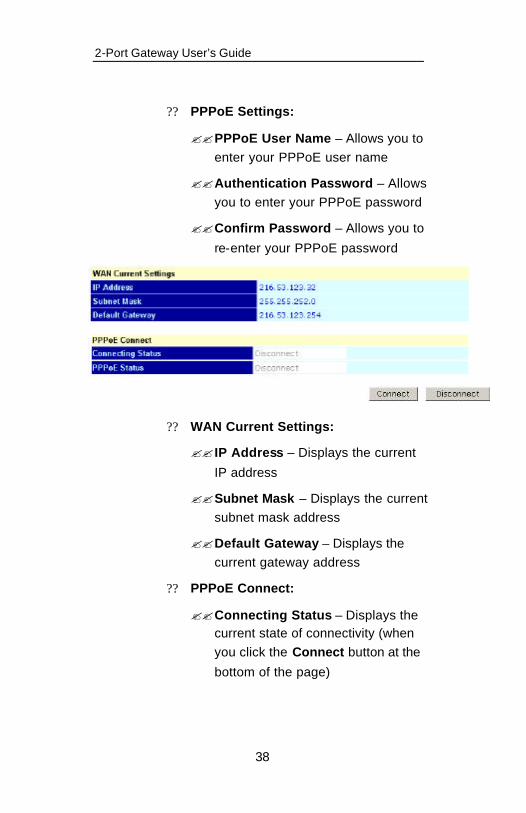
?? PPPoE Settings:
??PPPoE User Name – Allows you to enter your PPPoE user name
??Authentication Password – Allows you to enter your PPPoE password
??Confirm Password – Allows you to
re-enter your PPPoE password
?? WAN Current Settings:
?? IP Address – Displays the current
IP address
??Subnet Mask – Displays the current subnet mask address
??Default Gateway – Displays the current gateway address
?? PPPoE Connect:
??Connecting Status – Displays the current state of connectivity (when you click the Connect button at the
bottom of the page)

2-Port Gateway User’s Guide
39
??PPPoE Status – Shows the current PPPoE connection status, either connected or disconnected
For more information on setting up PPPoE, please refer to Setting up Point-to-Point Protocol over Ethernet (PPPoE) in Section 3.
LAN Configuration Page
The LAN Configuration page allows you to enter and save your LAN IP Address and LAN Netmask. It also allows you to enable/disable Dynamic IP assignment, as well as assign and save your LAN Static IP address and all
corresponding information.
2-Port Gateway User’s Guide
40
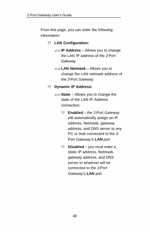
From this page, you can enter the following
information:
?? LAN Configuration:
?? IP Address – Allows you to change the LAN IP address of the 2-Port Gateway
??LAN Netmask – Allows you to change the LAN netmask address of the 2-Port Gateway
?? Dynamic IP Address:
??State – Allows you to change the state of the LAN IP Address
connection:
?? Enabled – the 2-Port Gateway will automatically assign an IP address, Netmask, gateway address, and DNS server to any PC or Hub connected to the 2-
Port Gateway’s LAN port
?? Disabled – you must enter a static IP address, Netmask, gateway address, and DNS server to whatever will be connected to the 2-Port
Gateway’s LAN port
2-Port Gateway User’s Guide
41
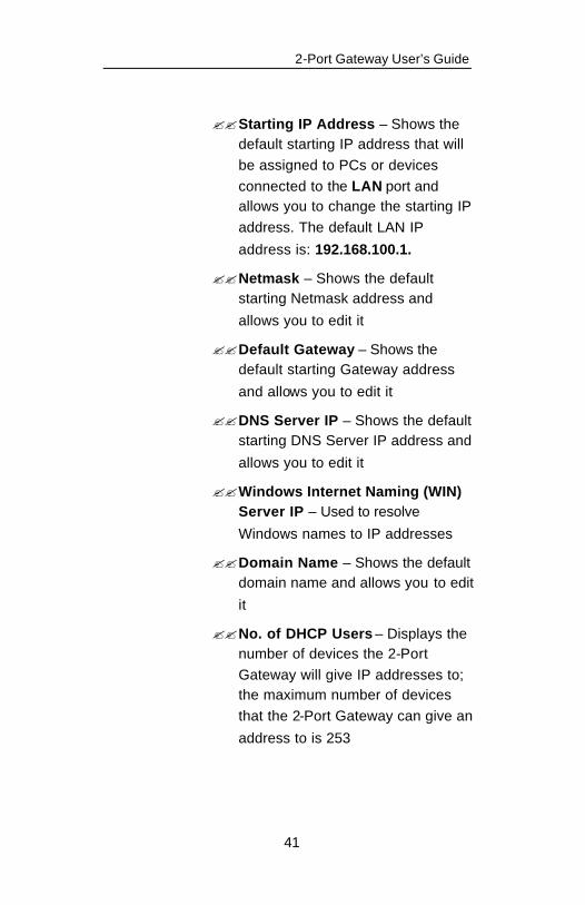
??Starting IP Address – Shows the default starting IP address that will be assigned to PCs or devices connected to the LAN port and allows you to change the starting IP address. The default LAN IP
address is: 192.168.100.1.
??Netmask – Shows the default starting Netmask address and
allows you to edit it
??Default Gateway – Shows the default starting Gateway address
and allows you to edit it
??DNS Server IP – Shows the default starting DNS Server IP address and
allows you to edit it
??Windows Internet Naming (WIN) Server IP – Used to resolve
Windows names to IP addresses
??Domain Name – Shows the default domain name and allows you to edit
it
??No. of DHCP Users – Displays the number of devices the 2-Port Gateway will give IP addresses to; the maximum number of devices that the 2-Port Gateway can give an
address to is 253
2-Port Gateway User’s Guide
42
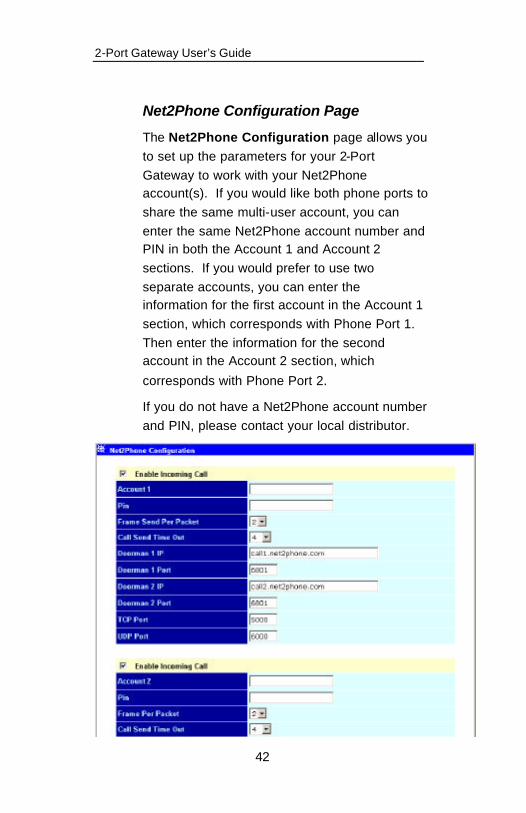
Net2Phone Configuration Page
The Net2Phone Configuration page allows you to set up the parameters for your 2-Port Gateway to work with your Net2Phone account(s). If you would like both phone ports to share the same multi-user account, you can enter the same Net2Phone account number and PIN in both the Account 1 and Account 2 sections. If you would prefer to use two separate accounts, you can enter the information for the first account in the Account 1 section, which corresponds with Phone Port 1. Then enter the information for the second account in the Account 2 section, which
corresponds with Phone Port 2.
If you do not have a Net2Phone account number and PIN, please contact your local distributor.
2-Port Gateway User’s Guide
43
From this page, you can enter all your Net2Phone
account information, including:
?? Enable Incoming Call check box – Allows you to select the phone port to allow incoming calls from other Net2Phone devices
Note: If you are sharing a multi-user account on both ports, you can only check Enable Incoming Call on one port at a time. In other words, both ports cannot accept incoming calls from other devices at the same time if they are sharing the same account number.
?? Account 1/Account 2 – Allows you to enter your Net2Phone account
number(s)
?? PIN – Allows you to enter your PIN number
?? Frames Sent Per Packet – Allows you to adjust the frames per packet on sent data to correct poor voice quality on
calls
?? Call Send Time Out – The amount of time after you finish dialing before the call will be sent to the Net2Phone platform; the default time is set to 4 seconds Note: You can also press # to initiate the call immediately.
2-Port Gateway User’s Guide
44
?? Doorman 1 and 2 IP – Allows you to enter a Doorman IP, if necessary. See, Configuring Firewall Ports, on the
following page, for more information
?? Doorman 1 and 2 Port – Allows you to select doorman ports. See Configuring Firewall Ports below for more
information.
?? TCP Port - Allows you to configure your TCP port. See Configuring Firewall
Ports below for more information.
?? UDP Port – Allows you to configure your UDP port. See Configuring Firewall
Ports below for more information.
Configuring Firewall Ports
The Net2Phone Configuration page also allows you to configure TCP ports, UDP ports, and doorman information. These fields should only be changed if you are not able to make a call due to a blockage between your device and the Net2Phone network. The default port
settings are listed below:
?? TCP/UDP Port Assignment – You can change the TCP/UDP ports on the firewall that the 2-Port Gateway utilizes and then specify those ports on the 2-Port Gateway (Default: TCP=5000,
UDP=6000)
?? Configurable Doorman Ports – In the event that the default doorman port

2-Port Gateway User’s Guide
45
becomes blocked (between the 2-Port Gateway and Net2Phone network), the 2-Port Gateway can be directed to a different port. Contact your distributor for an alternate port in the event that this becomes necessary (Default: 6801).
To change your TCP/UDP and Doorman Port
configuration:
1. Log in to the Web Management Tool following steps one, two and three on
pages 33 and 34.
2. Click the Configure Gateway Settings folder.
3. Click the Net2Phone Configuration menu item.
4. Enter the Doorman Port IP and the Port Number in the fields provided. In the event that the default doorman port becomes blocked (between the 2-Port Gateway and the Net2Phone network), the 2-Port Gateway can be directed to a different port. Contact your distributor for an alternate port in the event that this becomes necessary (Default: 6801).
5. Enter the TCP Port value numbers. You can change the TCP ports on the firewall that the 2-Port Gateway utilizes and then specify those ports to be used on the 2-Port Gateway (Default: TCP Port 1 = 5000, TCP Port 2 = 5050).

2-Port Gateway User’s Guide
46
6. Enter the UDP Port value numbers. You can change the UDP ports on the firewall that the 2-Port Gateway utilizes and then specify those ports to be used on the 2-Port Gateway. (Default: UDP Port 1 = 6000, UDP Port 2 = 6060).
7. Click the Save button to save the changes made to the Net2Phone Configuration page.
8. The 2-Port Gateway should prompt you to reboot the device. If not, reboot the 2-Port Gateway by unplugging the power cord from the back of the 2-Port Gateway, waiting three seconds, and plugging the power cord back in.
2-Port Gateway User’s Guide
47
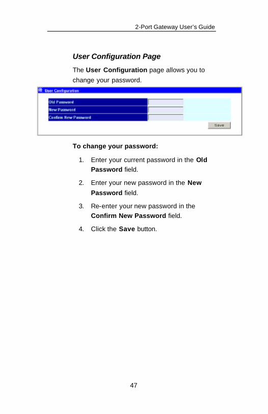
User Configuration Page
The User Configuration page allows you to
change your password.
To change your password:
1. Enter your current password in the Old Password field.
2. Enter your new password in the New
Password field.
3. Re-enter your new password in the Confirm New Password field.
4. Click the Save button.

2-Port Gateway User’s Guide
48
Configure Advanced Settings Folder
The Configure Advanced Settings folder contains three pages:
?? Telephony Configuration – Allows you to configure the receiving and transmission gain as well as the disconnected signaling
parameters
?? SNMP Trap Configuration – Allows you to configure the Trap Manager IP Address, the
Community Name, and the SNMP AuthTrap
?? Local Server Configuration – Allows you to edit the local server configuration
parameters
The following sections describe each page in detail.
2-Port Gateway User’s Guide
49
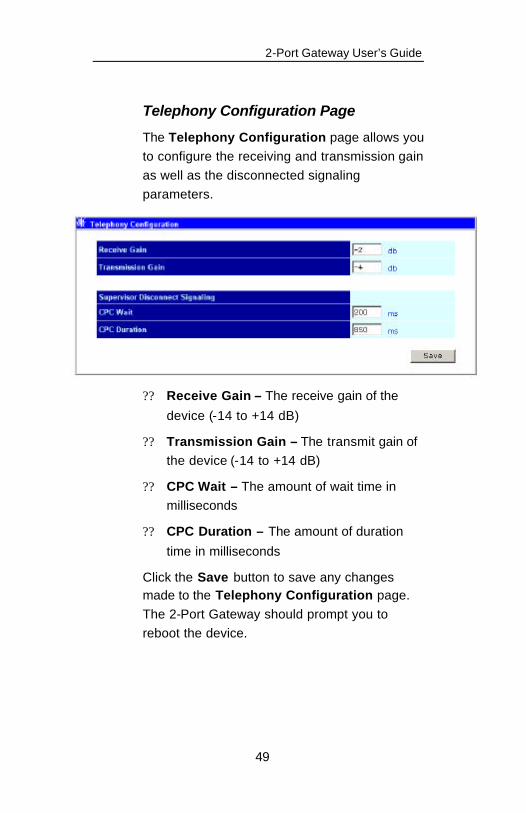
Telephony Configuration Page
The Telephony Configuration page allows you to configure the receiving and transmission gain as well as the disconnected signaling parameters.
?? Receive Gain – The receive gain of the
device (-14 to +14 dB)
?? Transmission Gain – The transmit gain of the device (-14 to +14 dB)
?? CPC Wait – The amount of wait time in milliseconds
?? CPC Duration – The amount of duration
time in milliseconds
Click the Save button to save any changes made to the Telephony Configuration page. The 2-Port Gateway should prompt you to reboot the device.

2-Port Gateway User’s Guide
50
SNMP Trap Configuration Page
The Simple Network Management Protocol (SNMP) Trap Configuration page allows you to
configure the following fields:
?? Trap Manager IP Address – The IP address of the trap receiving station
?? Community Name – A user-defined SNMP community name
?? SNMP AuthTrap – Enables or disables the SNMP trap
Click the Save button to save any changes made to the SNMP Trap Configuration page. The 2-Port Gateway should prompt you to
reboot the device.
2-Port Gateway User’s Guide
51
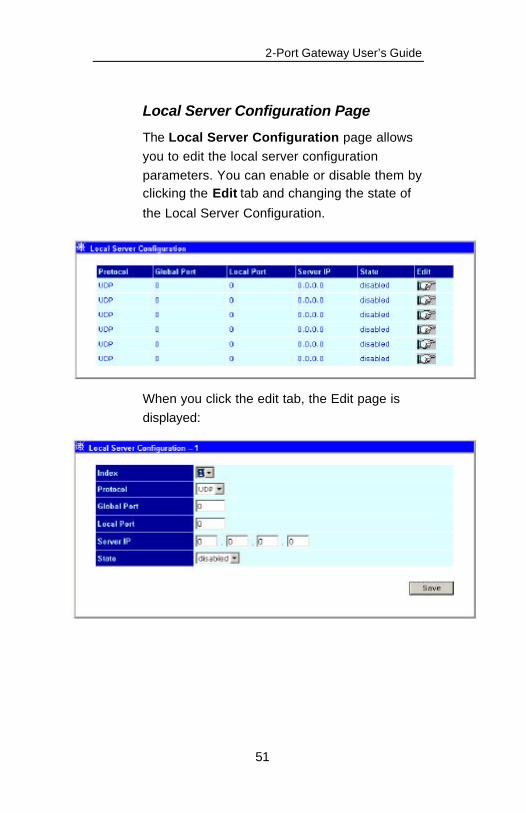
Local Server Configuration Page
The Local Server Configuration page allows you to edit the local server configuration parameters. You can enable or disable them by clicking the Edit tab and changing the state of
the Local Server Configuration.
When you click the edit tab, the Edit page is displayed:

2-Port Gateway User’s Guide
52
The items on this window are described below: ?? Index – Allows you to select the index
number you would like to edit (1 to 6)
?? Protocol - Allows you to select the protocol, either TCP or UDP
?? Global Port - Allows you to select the designated TCP or UDP protocol port number for the particular protocol packet you wish to redirect
?? Local Port - Allows you to select the port number used by the designated host on the LAN (or a well-known port)
?? Server IP - Allows you to select the IP address of the local designated host computer or device
?? State - Toggles between disabled and enabled for Local Server Configuration function
Click on the Save button to save any changes made to the Local Server Configuration page.

2-Port Gateway User’s Guide
53
Monitor Gateway Folder
The Monitor Gateway folder contains the following menu selections:
?? Ethernet Statistics – Allows you to view the Ethernet statistics for your LAN/WAN
connection
?? DSP Statistics – Allows you to view the statistics for the DSP Servers by Tcid port
setting
?? Tcid Configuration – Allows you to view the parameters for each Tcid port
The following sections describe each page in detail.
2-Port Gateway User’s Guide
54
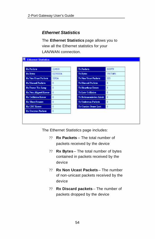
Ethernet Statistics
The Ethernet Statistics page allows you to view all the Ethernet statistics for your
LAN/WAN connection.
The Ethernet Statistics page includes:
?? Rx Packets – The total number of
packets received by the device
?? Rx Bytes – The total number of bytes contained in packets received by the
device
?? Rx Non Ucast Packets – The number of non-unicast packets received by the
device
?? Rx Discard packets – The number of packets dropped by the device

2-Port Gateway User’s Guide
55
?? Rx Frame Too Long – The number of packets that are larger than the 1514 Ethernet packet limit
?? Rx Non-Aligned Error – The number of
packets that are not aligned properly
?? Rx Collision Errors – The number of collision errors
?? Rx Short Frames – The number of packets smaller that the 64 octet
minimum
?? Rx CRC Errors – The number of packets received that failed the CRC
checksum test
?? Rx Overrun Packets – The number of packets received that exceed the 1518 octet maximum length imposed on Ethernet packets. Overrun packets are generated by some propriet ary software
applications
?? Tx Packets – The total number of valid packets transmitted by the device since
the last reset
?? Tx Bytes – The total number of bytes transmitted by the device
?? Tx Non Ucast Packets – The number
of non-unicast packets sent
?? Tx Discard Packets – The number of packets dropped by the device

2-Port Gateway User’s Guide
56
?? Tx Heartbeat Errors – The number of heartbeat errors (relates to an internal timing function)
?? Tx Late Collision – The number of late
collisions
?? Tx Retransmission Limit – The number of times the device can
retransmit packets
?? Tx Underrun Packets – This counter shows the number of runt packets transmitted by the device that are less than the allowed 64 octet minimum length. Underrun packets occur due to jam signals generated by collisions, backpressure, etc.
?? Tx Carrier Sense Lost – The number of times packets were lost due to carrier sense lost

2-Port Gateway User’s Guide
57
DSP Statistics
The Digital Signal Processor (DSP) Statistics page allows you to view the statistics for the
DSP Servers by Tcid port setting.
These statistics include:
?? Rx Voice Packets – The total number of voice packets received by the device
?? Rx Octets – The total number of Rx bytes received
?? Rx Min. Jitters – Minimum number of
received packets

2-Port Gateway User’s Guide
58
?? Rx Max Jitters – Maximum number of
received packets
?? Rx RTP Avg. Jitter – The average amount of Rx jitters per Tcid
?? Rx DTMF Octets – The number of Digital Time Multiplex Frequency
packets
?? Rx SID Packets – The number of received SID packets
?? Tx Voice Packets – The number of
transmitted voice packets
?? Tx Octets – The number of transmitted octets
?? Tx Silence Suppressed Frames – The number of transmitted silence
suppressed frame packets
?? Tx Grant Sync Dropped Frames – The number of transmitted grant Sync
dropped frame packets
?? Tx DTMF Octets – The number of transmitted Digital Time Multiplex
Frequency packets
?? AAL2 Coding Profile Changes – The number of AAL2 coding profile changes
?? Invalid Header Count – The number of
invalid header counts
?? Micro Overflow Count – The number of Micro overflow counts
2-Port Gateway User’s Guide
59
?? Lost Enh. Packets – The number of
lost enhanced packets
?? Missing Core Packets – The number of missing core packets
?? Pkts Lost by Network – The number of packets lost by the network
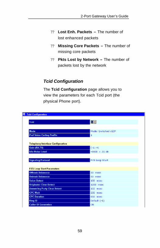
Tcid Configuration
The Tcid Configuration page allows you to view the parameters for each Tcid port (the
physical Phone port).
2-Port Gateway User’s Guide
60
You can view the following parameters for each
Tcid port:
?? Tcid number – Indicates the port of the device: 0 = Port 1, 1 = Port 2
??Mode – Displays the current protocol
??Pref. Voice coding profile – Displays the preferred voice coding profile
number
?? Telephony Interface Configuration:
??Gain (Rx/Tx) – The receiving and
transmitting volume gain
?? Idle Noise Level – The idle noise level in decibels
??Signaling Protocol – Displays the configured signaling protocol
?? FXS Loop Start Parameters:
??OffHook Debounce – Displays in milliseconds the offhook debounce
number
??OnHook Debounce – Displays in milliseconds the onhook debounce
number
??Seize Detect – Displays the seize detect rate
??Originator Clear Detect – Displays the
originator clear detect rate

2-Port Gateway User’s Guide
61
??Answering Party Clear detect – Displays the answering party clear detect rate
??CPC Wait – Displays the CPC wait time
??CPC Duration – Displays the CPC wait duration
??Ring ID – Displays the Ring ID number
??Caller ID Generation – Displays whether Caller ID generation is on or off
?? Dial Out Parameters:
??Out Wait – Displays the out wait time
??Out Type – Displays the out type tone
??Tone Out Off Time – Displays the tone out off time
??Tone Out On Time – Displays the tone
out on time
??Tone Out Power – Displays the tone out power level

2-Port Gateway User’s Guide
62
?? Echo Cancellation Parameters:
??Mode – Displays the echo cancellation mode
??Output – Displays the echo cancellation
output parameter
?? V.18A Tone Detect Parameters:
??Hangover – Displays the V.18A tone
detect hangover number
??Threshold – Displays the V.18A tone detect threshold number
??Fraction – Displays the V.18A tone detect fraction number
?? Other Parameters:
??Call Limit – Displays the call limit time in seconds
??Endpoint ID – Displays the Endpoint ID
2-Port Gateway User’s Guide
63
??Partial Digit Timer – Displays the
partial digital timer in seconds
??Critical Digit Timer – Displays the critical digital timer in seconds
??Service Class – Displays the service class
??Default Digit Map – Displays the
default digital map.
??Default Event List – Displays the default event list.
??Entity to be Notified – Displays the Web address for the entity to be notified.
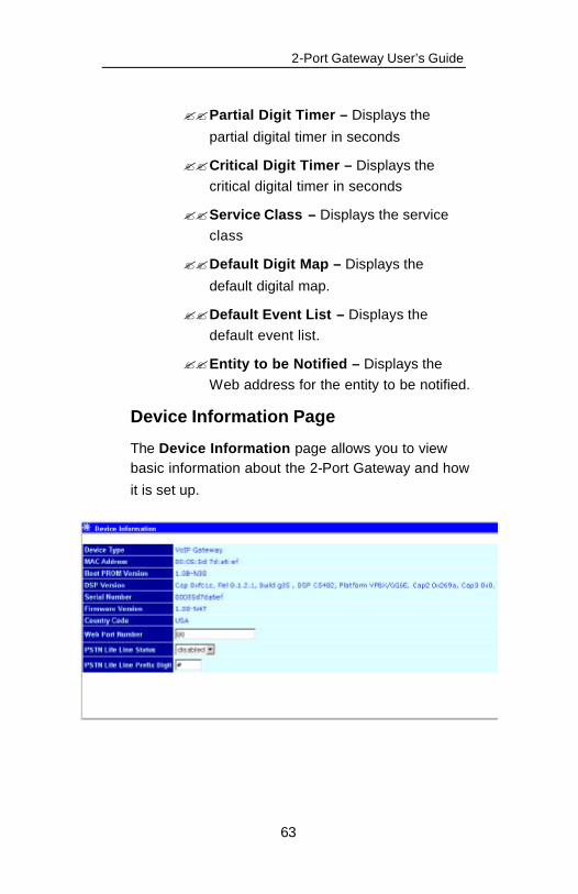
Device Information Page
The Device Information page allows you to view basic information about the 2-Port Gateway and how
it is set up.
2-Port Gateway User’s Guide
64
The following information is available on the Device
Information page:
?? Device Type – Displays a device definition of the 2-Port Gateway
?? MAC Address – The MAC (unique Ethernet) address of the 2-Port Gateway
?? Boot PROM Version – The Boot PROM
version on the 2-Port Gateway
?? DSP Version – The Digital Signal Processor software version number
?? Serial Number – The 2-Port Gateway serial number
?? Firmware Version – The current firmware
version installed on the 2-Port Gateway
?? Country Code – The country code associated with the 2-Port Gateway
?? Web Port Number – The port number the 2-Port Gateway uses as a Web server suffix
for the Web Management Tool
?? PSTN Life Line Status – Allows you to enable or disable the PSTN Life Line (For more information, please refer to The PSTN
Life Line in Section 5.)
?? PSTN Life Line prefix – Allows you to change the prefix that switches between IP
calling and regular calling (PSTN)
2-Port Gateway User’s Guide
65
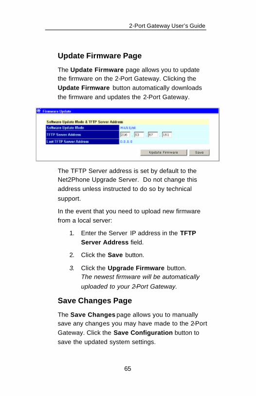
Update Firmware Page
The Update Firmware page allows you to update the firmware on the 2-Port Gateway. Clicking the Update Firmware button automatically downloads the firmware and updates the 2-Port Gateway.
The TFTP Server address is set by default to the Net2Phone Upgrade Server. Do not change this address unless instructed to do so by technical
support.
In the event that you need to upload new firmware from a local server:
1. Enter the Server IP address in the TFTP Server Address field.
2. Click the Save button.
3. Click the Upgrade Firmware button. The newest firmware will be automatically
uploaded to your 2-Port Gateway.
Save Changes Page
The Save Changes page allows you to manually save any changes you may have made to the 2-Port Gateway. Click the Save Configuration button to save the updated system settings.

2-Port Gateway User’s Guide
66
After the settings have been saved to NV-RAM, they will become the default settings for the 2-Port Gateway, and they will be used every time the device is powered on, reset, or rebooted. The only exception to this is a factory reset, which will clear all settings and restore them to their original factory settings.

2-Port Gateway User’s Guide
67
Reset Page
The Reset page returns all your settings to the original factory presets. Click the Reset To Factory
Default button to perform the reset.
Caution: This will reset any IP configurations and account information you have saved into the 2-Port
Gateway.
Restart Gateway Page
The Restart page allows you to restart the system.
Simply click the Restart button to restart the system.

2-Port Gateway User’s Guide
68
Note: If you make changes to the settings on any of the Web Management Tool pages, click Save Changes before restarting the 2-Port Gateway. Otherwise, the changes will be lost after the restart.

2-Port Gateway User’s Guide
69
5. Placing and Receiving Calls
Overview
Placing calls using the 2-Port Gateway is almost as easy as placing a regular phone call – with added benefits. Not only can you place calls to and receive calls from any telephone in the world, you can also communicate with other 2-Port Gateway devices and other Net2Phone devices. This section offers instructions on placing and receiving different types
of calls with the 2-Port Gateway.
Note: You must have Internet connectivity to place and receive calls. If there is a problem with your Internet connection, see Connecting to the Internet on page
30.
Calling Regular Telephones
Calls within North America To place a call within North America using
your 2-Port Gateway:
1. Pick up the handset of a telephone connected to one of the 2-Port Gateway’s
ports and listen for a dial tone.
2-Port Gateway User’s Guide
70
2. Using your telephone keypad, dial 1 + the area code + the local number. For example, if the area code is 212 and the local number is 555-6791, you would
dial 1 212 5556791.
3. When you have finished your call, simply hang up your telephone handset.
Note: You can either wait 4 seconds after dialing the last digit for the call to commence or press the # key after you’ve finished dialing to begin the call. (Four seconds is the default wait time before the 2-Port Gateway will place a call; this time value can be changed on the Net2Phone Configuration page in the Web
Management Tool.)
International calls To place an international call with your 2-
Port Gateway:
1. Pick up the handset of a telephone connected to one of the 2-Port Gateway’s
ports and listen for a dial tone.
2. Using your telephone keypad, dial 011 + the country code + the city code + the local number. For example, if the country code is 9, the city code is 81, and the local number is 223-
4567, you would dial 011 9 81 2234567.
2-Port Gateway User’s Guide
71
Note: You can either wait 4 seconds after dialing the last digit for the call to commence or press the # key after you’ve finished dialing to begin the call. (Four seconds is the default wait time before the 2-Port Gateway will place a call; this time value can be changed on the Net2Phone Configuration page in the Web Management Tool.)
Note: If you try to place a call and get a fast busy signal, it means the call could not be completed due to one of a variety of reasons listed below: ?? an unauthorized number was dialed ?? the party you dialed is busy ?? the party you dialed is not logged on ?? the party you called does not
answer ?? your account and PIN are wrong ?? your account is out of funds ?? your account is already in use ?? your account is disabled ?? the call cannot be completed
because of your network configuration
?? the call cannot be completed because of a PSTN carrier problem
2-Port Gateway User’s Guide
72
Calling other Net2Phone Devices
A call from one Net2Phone device to another Net2Phone device is known as a device-to-device
call.
Calling another Net2Phone Device
To place a call to another Net2Phone device:
1. Pick up the handset of a telephone connected to one of the 2-Port Gateway’s
ports and listen for a dial tone.
2. Using your telephone keypad, dial *72 + the first 10 digits of the account number on the
device of the person you want to call.
3. When you have finished your call, simply hang up your telephone handset. For example, if you are using a telephone connected to a 2-Port Gateway in New York City to place a call to a telephone connected to a 2-Port Gateway in Los Angeles, and the account number assigned to the 2-Port Gateway you are calling is 1234567890, you
would dial *72 1234567890.
Receiving a Call from Another Net2Phone Device
To receive an incoming call from another
Net2Phone device:
1. When a call comes in, pick up your telephone handset and talk as usual.
2. When you have finished your call, simply hang up your telephone handset.
2-Port Gateway User’s Guide
73
The PSTN Life Line
The PSTN Life Line port allows you to use a telephone connected to your 2-Port Gateway to access a PSTN analog line to make regular telephone calls. If your network goes down and you are unable to connect to the Internet, or if you need to place an emergency call, you can use your normal telephone line, bypassing the Internet.
To set up your PSTN Life Line:
1. Access the Device Information page in the Web Management Tool to confirm that the
PSTN Life Line Status is disabled.
2. Connect an RJ-11 cable from your 2-Port Gateway PSTN Life Line port to any active
PSTN analog phone line.
Note: The # key is the default toggle key for switching between PSTN and Internet calls. You can designate a different toggle key on the phones attached to the 2-Port Gateway by accessing the Device Information page in the Web Management Tool. Enter a different key in the PSTN Life Line Prefix Digit field and save your changes.
2-Port Gateway User’s Guide
74
On the Device Information page of the Web Management Tool, the PSTN Life Line Status defaults to disabled. When this status is disabled, the 2-Port Gateway defaults to an IP dial tone when you pick up one of the phones
attached to the 2-Port Gateway.
Note: The recommended setting for the PSTN Life Line Status is disabled, allowing you to place both Internet-based and regular (PSTN-based) calls. Enabling the PSTN Life Line Status would restrict your telephone to regular (PSTN -based) calls ONLY.
To access a regular (PSTN) telephone line:
1. Pick up the handset on an analog telephone
attached to your 2-Port Gateway.
2. Press the # key. You should now hear your regular PSTN dial
tone.
3. Place your call.
Note: To switch back to Internet calling, hang up the phone after your call is completed. (Pressing the # key DOES NOT switch you back to IP calling after a PSTN call has been
placed.)

2-Port Gateway User’s Guide
75
APPENDICES Appendix A – Troubleshooting
Common mechanical installation problems
If there appears to be a malfunction, first check all cables and connections. If these appear to be in order, see the following table for specific troubles and solutions.
Symptom Possible
Cause
Corrective
Action Power source switched off
Switch power source ON
Faulty power cable Check/replace power cable
Faulty power source
Check/correct input power
Power LED off
Faulty internal power supply
Contact your distributor
Faulty console terminal
Check/replace terminal
Faulty cabling to terminal
Check/replace cable
No initialization response from 2-Port Gateway Faulty 2-Port
Gateway Contact your distributor
Overheating Check ventilation Unit shuts off after operating for some time
Faulty 2-Port Gateway
Contact your distributor
Console fault Reset/replace console
Software error Repeat power-up procedure
Web Management Tool or Console page display freezes
Faulty 2-Port Gateway
Contact your distributor

2-Port Gateway User’s Guide
76
Common network connection problems
My network supports DHCP, but my 2-Port Gateway cannot obtain correct network settings.
?? Make sure DHCP is enabled. ?? Make sure the RJ-45 LAN cable is connected
securely to your 2-Port Gateway and LAN, hub, or router.
?? Make sure that all network ports, routers, or hubs are live.
I set DHCP to ON, but my 2-Port Gateway cannot
obtain correct network settings. ?? Make sure your network supports DHCP. ?? Make sure your RJ-45 LAN cable is securely
connected to both the 2-Port Gateway and to the LAN, hub, or router.
?? Make sure that all network ports, routers, or hubs are live.
When I enter a static IP Address into my 2-Port Gateway and restart the unit, the IP Address I entered is not saved.
?? Make sure DHCP is set to OFF.
When I attempt to access the Web Management Tool, I am prompted for a user name and password. But when I enter them and press the
OK button, the password page reappears.
?? Make sure both the user name and password are correct (Note that the user name and password are case sensitive). The default user name is admin. The default password is
n2p.
2-Port Gateway User’s Guide
77
Common configuration problems
In the Web Configuration page, I omitted the DNS Server field because it does not apply to me, but now the Web Configuration will not let me save the settings.
?? The DNS fields must not be left blank. If you do not wish to enter DNS Servers, you must
enter 0.0.0.0 in those fields.
Common Internet connectivity problems
I set up my WAN configuration and rebooted my 2-Port Gateway, but I’m unable to connect to the
Internet.
If you do not have Internet connectivity, try the following:
1. Verify that all cables are connected properly.
2. Verify that all WAN settings are correct.
3. Verify that your PC is getting an IP address
from the 2-Port Gateway by:
a. On your Windows task bar, click the Start menu button:
The Start menu displays.
b. Click Run to access the Run window: The Run window opens.
c. Type COMMAND or CMD in the Open field and click the OK button.
The DOS prompt window displays.
2-Port Gateway User’s Guide
78
d. From the DOS C:\> prompt, type: ipconfig and press the Enter key. The command window opens.
e. The IP address displayed should be 192.168.100.xx.
4. Try rebooting the DSL/cable modem to which the 2-Port Gateway is connected to reset the IP address for the 2-Port Gateway.
5. Contact your network administrator or
broadband service provider.
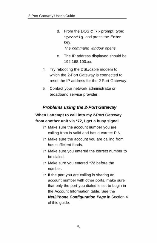
Problems using the 2-Port Gateway
When I attempt to call into my 2-Port Gateway
from another unit via *72, I get a busy signal.
?? Make sure the account number you are calling from is valid and has a correct PIN.
?? Make sure the account you are calling from has sufficient funds.
?? Make sure you entered the correct number to be dialed.
?? Make sure you entered *72 before the number.
?? If the port you are calling is sharing an account number with other ports, make sure that only the port you dialed is set to Login in the Account Information table. See the Net2Phone Configuration Page in Section 4 of this guide.

2-Port Gateway User’s Guide
79
Appendix B – Technical Support
If you are experiencing a technical problem, please refer to Appendix A, Troubleshooting, in this Guide. If the problem remains unresolved, please contact your reseller for assistance.
Do not attempt to disassemble the 2-Port Gateway. There are no user-serviceable parts inside the unit.

User’s Guide Appendix C
80
Appendix C – System Specifications
Analog voice interface
FXS, RJ-11 (NET2PHONE)
LAN interface 10baseT, RJ-45, 1 port
Serial interface EIA-232 {old RS-232C}, DB-9, 1 port Asynchronous serial communication at 19200bps
LED indicators
one active status indicator for system one alarm indicator for system malfunction one active status indicator for each analog voice port
one LAN link indicator
one LAN data receive indicator
VoIP protocol Net2Phone proprietary protocol
Voice processing capabilities
{compression/ decompression} {QoS related capabilities}
G.711
G.723.1
Echo Cancellation (G.168)
Voice Activity Detection
Comfort Noise Generation
Management interface
Command line interface via console port or telnet client
Web interface via any Web browser
Physical Size (H x W x D)
49.5 x 212.6 x 177.6 mm
Weight 0.5 Kg.
Input power 5V AC/DC adaptor: input 100 - 240 VAC, 1.5 A (max.),
50/60 Hz, 50 W (max.)
Main processor Motorola MPC850DSL
2-Port Gateway User’s Guide
81
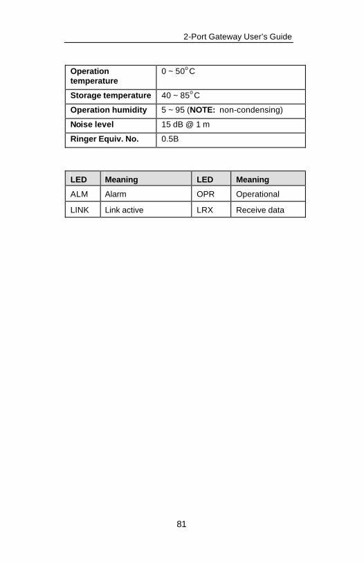
Operation temperature
0 ~ 50o C
Storage temperature 40 ~ 85o C
Operation humidity 5 ~ 95 (NOTE: non-condensing)
Noise level 15 dB @ 1 m
Ringer Equiv. No. 0.5B
LED Meaning LED Meaning
ALM Alarm OPR Operational
LINK Link active LRX Receive data
User’s Guide Appendix E
82
Appendix D – Approvals and Listings
FCC Declaration of Conformity
?? Product name: 2 -Port Gateway ?? FCC Rules: Tested to comply with FCC part
15, Class A & FCC part 68 ?? Operating environment: for office use
FCC Compliance Statement:
This device complies with Part 15 of the FCC Rules. Operation is subject to the following two conditions: (1) This device may not cause harmful interference, and (2) this device must accept any interference received, including interference that may cause undesired operation.
For 2-Port Gateway
FCC Declaration of Conformity
?? Product name: 2 -Port Gateway ?? FCC Rules: Tested to comply with FCC part
15, Class A ?? Operating environment: for office use
FCC Compliance Statement:
This device complies with Part 15 of the FCC Rules. Operation is subject to the following two conditions: (1) This device may not cause harmful interference, and (2) this device must accept any interference received, including interference that may cause
undesired operation.
2-Port Gateway User’s Guide
83
Important! Changes or modifications not expressly approved by the manufacturer could void the user’s authority to operate the equipment. Use with an approved telephone set.
Party responsible for product compliance:
Net2Phone, Inc.
520 Broad Street
Newark, NJ 07102
USA
LISTED I.T.E
E176683


![Untitled-3 [] · ADAM-4570/ADAM-4571/EDG-4504 1/2/4 Port Ethernet to RS-232/422/485 Data Gateway User’s Manual](https://static.fdocuments.in/doc/165x107/5f02c5e37e708231d405f065/untitled-3-adam-4570adam-4571edg-4504-124-port-ethernet-to-rs-232422485.jpg)