Инструкция Mystery MMW-1706 · Микроволновые печи Mystery MMW-1706: Инструкция пользователя. ...

Cascade Microtech Europe LtdGavin Fisher
A guide to Successful on Wafer Millimeter waveRf characterisation

Company Confidential
See It. Touch It. Measure It.
Agenda
The need for on-wafer S-parameter MeasurementsTypical system components and station specificsMicrowave ProbesProbe Station EssentialsProbe Tip Calibration How to CalibrateDevice for testability

Company Confidential
See It. Touch It. Measure It.
Why do we need on Wafer Characterisation

Company Confidential
See It. Touch It. Measure It.
The need for on-wafer Characterisation?
We want to know the true performance of the device and not the device plus package
• De-embedding can be used but introduces additional errors and uncertainties
We want to determine ‘known good die’ to reduce packaging cost and increase yields
• Some RF packages can be very expensive and die yield can be low
We want to automate the measurements• Being able to test wafers automatically can be cost
effective and fast

Company Confidential
See It. Touch It. Measure It.
Typical 110 GHz System
Vector Network Analyzer
Cables
Probes
Probe positioners
Probe station
Contact Substrate
Calibration Substrate
Calibration Software
Bias supply
Microscope

Company Confidential
See It. Touch It. Measure It.
Large area linear lift positioner

Company Confidential
See It. Touch It. Measure It.
110 GHz Probes and Accessories

Company Confidential
See It. Touch It. Measure It.
220 GHz Probes / Waveguides

Company Confidential
See It. Touch It. Measure It.
110 GHz Probe connection scheme

Company Confidential
See It. Touch It. Measure It.
Semi-Automatic 220 GHz System

Company Confidential
See It. Touch It. Measure It.
Manual 220 GHz System
Quick release manual stageallows Evue microscope for rapidaccurate probe set-upDeluxe anti-vibration tableprovides convenient monitor / keyboard mounts

Company Confidential
See It. Touch It. Measure It.
220 GHz Probe connection scheme

Microwave Probes

Company Confidential
See It. Touch It. Measure It.
Air Co-Planar Transition
Probe transitions from coaxial to co-planar waveguideFabricated probe tips
• Uniform and compliant probe contacts• Tight Impedance control

Company Confidential
See It. Touch It. Measure It.
ACP Series Probe
Block
Connector
Absorber
Low-Loss CableMetal CPW Tip
Absorber
Ideal for High PowerMeasurements up to 200degCLarge 25um compliance between tipsBeCu or W 15 W CW at 10 GHz5 A DC current
Company Confidential
See It. Touch It. Measure It.
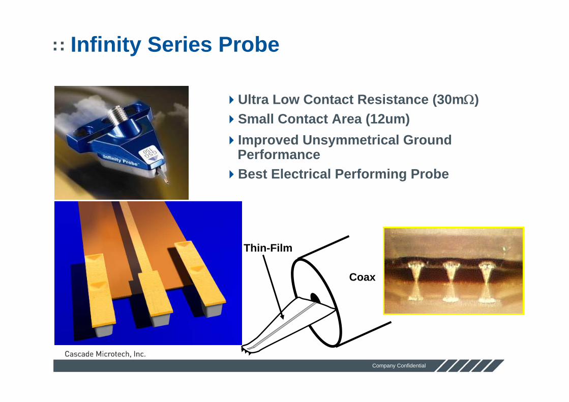
Infinity Series Probe
Ultra Low Contact Resistance (30mΩ)Small Contact Area (12um)Improved Unsymmetrical Ground PerformanceBest Electrical Performing Probe
Thin-Film
Coax

Company Confidential
See It. Touch It. Measure It.
0
0.05
0.1
0.15
0.2
0.25
0 1000 2000 3000 4000 5000Contact Cycle
Rc
( Ω)
Conventional Tungsten Probe
Infinity Probe
Repeatability
Typical results: Contact resistance
Contact resistance on un-patterned aluminum averages about 30 mΩ over 5000 contact cycles at ambient

Company Confidential
See It. Touch It. Measure It.
New Infinity Waveguide Probe
Waveguide/flangeWR15 – 50-75GHzWR12 – 67-90GHzWR10 – 75-110GHzWR8 – 90-140GHzWR6 – 110-170GHzWR5 – 140-220GHzWR3 - 220-325GHz (en
2005)
Standard probe mount
SSMC bias T connector
Membrane coupon

Company Confidential
See It. Touch It. Measure It.
Contact Marks on Aluminum Pads
• Reduced pad damage• Contact marks (15 x 40 um)
• Good Tip visibility

Company Confidential
See It. Touch It. Measure It.
Non-symmetrical Grounds
GSG pads shield like CPW
GS pads fringe to the ground plane or chuck
Fields terminate on backside of wafer
on one side

Company Confidential
See It. Touch It. Measure It.
Effects of Non-symmetrical Grounds
Non-symmetrical grounds can cause resonance loops even at frequencies <10GHz

Company Confidential
See It. Touch It. Measure It.
Infinity Probe Tip Shielding
DUTCoplanar probe tips do not shield from the DUT
DUTMicrostrip structure shields signal line better

Company Confidential
See It. Touch It. Measure It.
110GHz Cal - ACP versus Infinity
Much lower uncertainty due to lower mode content in Infinity Probe
ACP Cal Response
InfinityCal Response

Probe Station Essentials

Company Confidential
See It. Touch It. Measure It.
Dry, Frost Free environmentAuxiliary ChucksRoll-out chuckStable repeatable platenTop-Hat
MicroChamberTM Technology

Company Confidential
See It. Touch It. Measure It.
Shielded Environment
Shielding Shielding TechnologyTechnology
• EMI Gaskets
• Silver loaded slits
• Steel lens cover
• Steel top hat cover

Company Confidential
See It. Touch It. Measure It.
MicroChamberTM Technology
Completely Integrated Measurement Environment
• FULL access to Positioners, Stage and Microscope
• Roll-out stage – Complete chuck, not just top layer
- Easy, fast & safe wafer loading

Company Confidential
See It. Touch It. Measure It.
RF & DC Cabling
Triax connection panels• Easy power supply
connections• Cable strain relief
Goretm RF cables• Low Loss• Phase stable• Flexible
N5250 110 GHz pna has in-built triaxial bias tees as optionWaveguide Infinity probes has bias tee built in as an option

Company Confidential
See It. Touch It. Measure It.
Evue Microscopy
Alignment of probes for mmwwork is extremely importantAccuracy better than 5 um requiredSimultaneous view of high and low magnification helps ensure safety of valuable mmw probesAuto z helps ensure that repeatable contact is maintained on warped thinned wafer

Company Confidential
See It. Touch It. Measure It.
Evue – three simultaneous views

Company Confidential
See It. Touch It. Measure It.
Evue – Positioning assessment

Company Confidential
See It. Touch It. Measure It.
Evue – device identification

Company Confidential
See It. Touch It. Measure It.
Evue – Auto xyz
Auto xyz asessescontact X/Y/Z changes die by die using evueWafer profiling automatically profiles the whole wafer using evue in a single one time operation prior to test

Probe Tip Calibration

Company Confidential
See It. Touch It. Measure It.
Principle Calibration Techniques
SOLT Short Open Load ThruSOLR Short Open Load ReciprocalLRM Line Reflect MatchLRRM Line Reflect Reflect MatchTRL Thru Reflect Line

Company Confidential
See It. Touch It. Measure It.
Uncorrected VNA
Average > -10dB
10db >S11 Load
Similar to Open & S21
Similar to S11 & S22 Open/Short

Company Confidential
See It. Touch It. Measure It.
General PNA Recommendations
Signal-to-noise ratio degrades calibration• Use < 300Hz IF bandwidth with no averaging
- Can be increased after calibration• Use high RF Power
- Stay within DUT linear output limits• Use the least amount of necessary attention
- Port 1 normally < 10dB for SS gain devices- Port 2 normally Zero for SS gain devices
• Use shortest possible low loss cables- Gore is best
Maintain constant temperature

Company Confidential
See It. Touch It. Measure It.
SOL 1-Port Calibration
Only calibration technique Works on all PNAsPNA front panel supported
• Requires PNA cal kitWinCal supportedRequires rigorous definitions

Company Confidential
See It. Touch It. Measure It.
SOLT 2-Port Calibration
Works on all PNAsOldest calibration techniquePNA front panel supported
• Requires PNA cal kit WinCal supportedRequires rigorous definitionsLooks best after calibrationLess accurate than LRM & LRRM

Company Confidential
See It. Touch It. Measure It.
SOLT Calibration
All standards must be perfectly known• Available every vector network analyzer (CalKit
required)• Open has capacitance (often negative)• Short and load have inductance
Sensitive to probe placementMathematically over-determinedUnpredictable behavior
DelayThru
Thru
Short Open(probes in air)
Load
Lterm
Lshort Copen

Company Confidential
See It. Touch It. Measure It.
SOLT Calibration Results
All standards match their cal kit definitionsEven bad standards will look good
• Must verify with other devices

Company Confidential
See It. Touch It. Measure It.
SOLT Calibration Results
Open stub• Not centered on the Smith chart• Lines crossing
S21 always exhibits ripple• Bad artifact of the SOLT cal

Company Confidential
See It. Touch It. Measure It.
SOL-R 2-Port Calibration
Works on PNAsNot PNA front panel supportedWinCal supportedRequires no THRU definitionRecommended for dual probes, right angle probes & probe cards

Company Confidential
See It. Touch It. Measure It.
SOL-R Calibration
Short-Open-Load-Reciprocal Thru
• Reciprocal Thru requires only S12 = S21• Tolerant to lossy or highly reactive insertion
standard• Convenient for use with fixed probe spacing in
probe cards• Does not require a custom Thru• Convenient for use when DUT terminals are
orientated at 90°• Available in WinCal (not front panel)
Short
Open(probes in air)
Load
Reciprocal
OR

Company Confidential
See It. Touch It. Measure It.
SOL-R Calibration Results
Short, Open & Load match the SOL definitions

Company Confidential
See It. Touch It. Measure It.
SOL-R Calibration Results
Open Stub• Not centered on the
Smith chart• Lines are crossing

Company Confidential
See It. Touch It. Measure It.
SOL-R Calibration Results
Thru is least accurate of all calibration types
• Best method for right angle probing and probe cards

Company Confidential
See It. Touch It. Measure It.
Right Angle Measurements
Carefully constructed right angle ‘Thru’ standardThru is non-ideal, large dip at 20 GHz Errors in standard cal’sSOLR immune to Thru errors
-1.0
-0.5
0.0
0.5
1.0
0 5 10 15 20 25 30 35 40 45 50
|S21|[dB]
[GHz]
Orthogonal SOLT
Orthogonal SOLR
Straight LRRM
Orthogonal LRRM

Company Confidential
See It. Touch It. Measure It.
TRL 2-Port Calibration
Preferred by engineers for on-wafer microstrip embedded devices
• Cannot realize 50 Ohm lines exactlyMost popular for mmW GaAsHard to get broadband standards
• Dispersive below 5 GHz• Long lines require too much wafer real estate

Company Confidential
See It. Touch It. Measure It.
TRL/LRM Calibration
Thru-Reflect-Line• Requires least info about standards• S-parameters referenced to line Zo• Reference plane at center of Thru• Requires multiple probe spacings• Zo is inherently complex at low frequencies• Not suitable for fixed spacing probes (e.g.,
probe card)Line-Reflect-Match
• Referenced to Zmatch
Thru
Line(s)
Reflect
Match
OR

Company Confidential
See It. Touch It. Measure It.
TRL Calibration Results
All standards exhibit large anomalies

Company Confidential
See It. Touch It. Measure It.
TRL Calibration Results
Open stub is well centered on the Smith chartNo lines are crossing

Company Confidential
See It. Touch It. Measure It.
TRL Calibration Results
Thru line exhibits excessive loss

Company Confidential
See It. Touch It. Measure It.
TRL Measurement Problems
Very poor below 5 GHzPropagation not constant for thin film structures
Apparent dispersion of a lumped element

Company Confidential
See It. Touch It. Measure It.
TRL Measurement Problems
Discontinuitiesat the delay linedefinitions

Company Confidential
See It. Touch It. Measure It.
LRM 2-Port Calibration
Works on all PNAsPNA front panel supported
• Requires VNA cal kitWinCal supported
• Automatic load inductance enhancedBetter than SOLT

Company Confidential
See It. Touch It. Measure It.
LRM Calibration Results
All standards have visibly small anomaliesResults approximate SOLT cal definitions

Company Confidential
See It. Touch It. Measure It.
LRM Calibration Results
Opens from LRM (open –load) exhibit non-linear characteristicsOpens from LRM (short –load) introduce additional rippleRecommend LRM (open –load)

Company Confidential
See It. Touch It. Measure It.
Open Response After LRRM/LRM Calibration – ACP Probes

Company Confidential
See It. Touch It. Measure It.
Open Response After LRRM/LRM Calibration – Infinity ProbesAlmost ideal2 to 10 X better than ACP or GGBSOLT always yields perfect response

Company Confidential
See It. Touch It. Measure It.
LRM Calibration Results
Open stub is well centered on the Smith chartNo lines are crossing

Company Confidential
See It. Touch It. Measure It.
LRM Recommendations
Best PNA front panel cal• Does not require WinCal
Gives better results than SOLT• Less fine grain ripple artifacts• Less sensitive to probe placement errors
WinCal LRM open-load with automatic load inductance • Better than PNA front panel LRM
Company Confidential
See It. Touch It. Measure It.
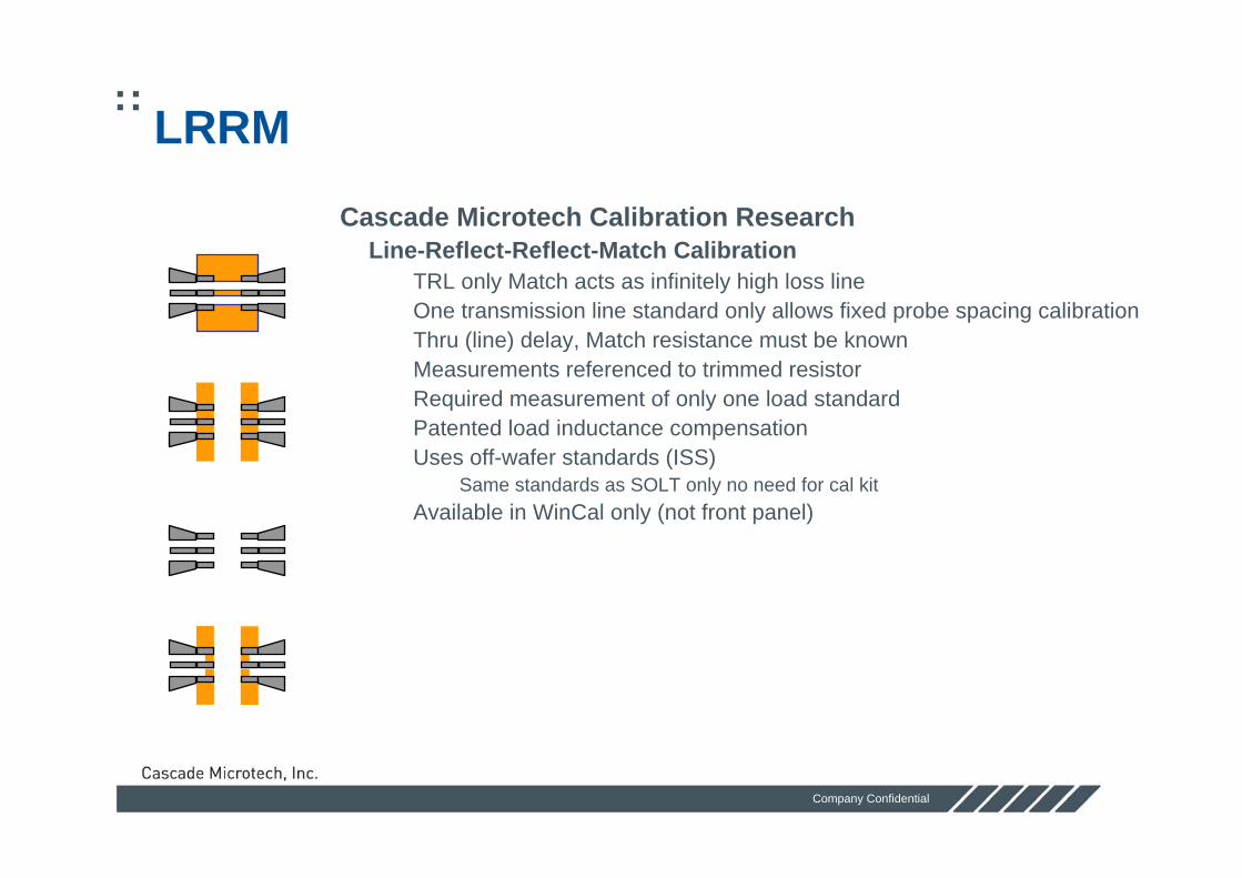
LRRM
Cascade Microtech Calibration ResearchLine-Reflect-Reflect-Match Calibration
• TRL only Match acts as infinitely high loss line• One transmission line standard only allows fixed probe spacing calibration• Thru (line) delay, Match resistance must be known • Measurements referenced to trimmed resistor• Required measurement of only one load standard• Patented load inductance compensation• Uses off-wafer standards (ISS)
- Same standards as SOLT only no need for cal kit• Available in WinCal only (not front panel)
Line
Reflect
Reflect(probes in air)
Match

Company Confidential
See It. Touch It. Measure It.
LRRM Requires only 1 Load
Easier to put standards on the wafer
• Only the dc (kelvin) resistance required
• LRM requires two matched loads
Used Load
Unused Load

Company Confidential
See It. Touch It. Measure It.
NIST Verification
System drift baseline LRRM compares with system drift limit
best fixed probe position calibration
SOLT /LRMgrowing error w/freqpossible CalKit errorpossible ref plane error

Company Confidential
See It. Touch It. Measure It.
How repeatable is my calibration?
LRRM automatic calibration is VERY repeatable
Wor
st c
ase
devi
atio
n
Frequency (GHz)
10 LRRM calibration verifications using NIST Verify software
0.3% Spread
Company Confidential
See It. Touch It. Measure It.
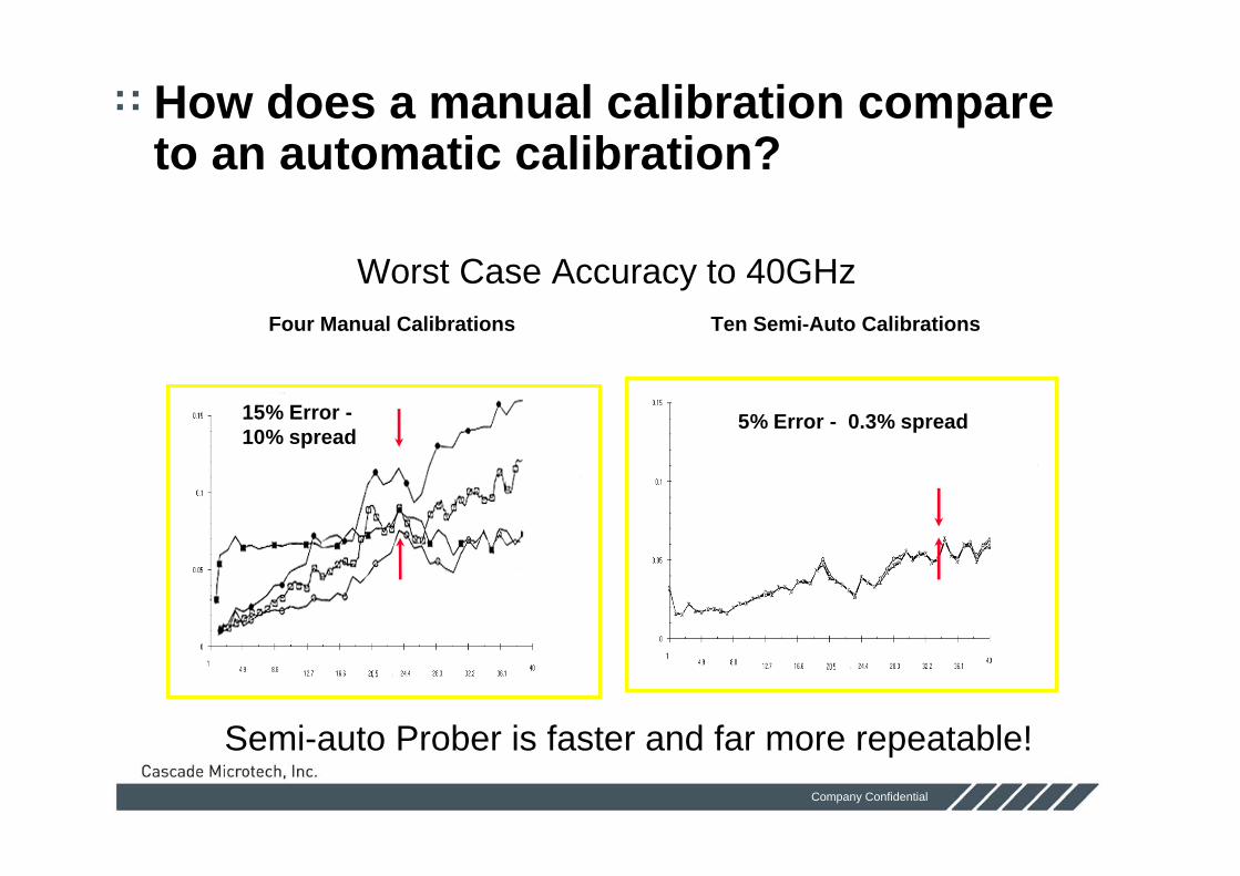
How does a manual calibration compare to an automatic calibration?
Worst Case Accuracy to 40GHz
Semi-auto Prober is faster and far more repeatable!
Four Manual Calibrations Ten Semi-Auto Calibrations
5% Error - 0.3% spread15% Error -10% spread

Company Confidential
See It. Touch It. Measure It.
How repeatable are the calibration standards?
Impedance Standard Substrate Standards are very repeatableW
orst
cas
e de
viat
ion
Frequency (GHz)
10 Different LRRM calibration verifications using NIST Verify software
3% Spread

Company Confidential
See It. Touch It. Measure It.
Which Calibration Technique is Best?
SOLT• All Hi-Q measurements <20GHz• Most measurements requiring attenuation• Most measurement <-10dBm input power
SOLR• All probe card applications• All dual signal probe applications• Right angle probe applications

Company Confidential
See It. Touch It. Measure It.
Which Calibration Technique is Best?
LRM (with auto load inductance)• Most accurate attenuation measurements• Some on-wafer standards
LRRM (with auto load inductance)• Best for broadband mmW transistors• On-wafer standards with a single load
TRL• Microstrip mmW device characterization• Waveguide banded measurements• III-V on-wafer mmW microstrip standards

Company Confidential
See It. Touch It. Measure It.
Impedance Standard Substrate

Company Confidential
See It. Touch It. Measure It.
Absorbing ISS holder Measurements > 50 GHz, unwanted modes are excited
Microwave absorbing ISS holder reduces unwanted modes (PN 116-344)
• Ideal for LRRM, LRM & SOL-R calibrations
ISS enhanced for CPW transmission mode –thinned to 10 mils (PN 104-783)

How to calibrate

Company Confidential
See It. Touch It. Measure It.
How to calibrate
Ensure that the probes are in placeClean and connect the cables and torque using relevant wrench
• Use IPA and swab to clean connectors and allow to dry
Visually inspect the probe tips and clean if contaminated
• Use IPA and swab, brushing away from the probe body and allow to dry for ACP
• Use probe clean for InfinityPlanarize the probes on the Contact Substrate inspecting the probe marks for even GSG contacts
• Adjust the positioner planarity until all tips make even contact

Company Confidential
See It. Touch It. Measure It.
Planarizing the Probes
Contact Substrate • PN 005-018• Dull gold finish• Bright contact marks
Adjust planarity until equal marks from all probe contacts

Company Confidential
See It. Touch It. Measure It.
ISS Alignment Marks
Sets probes overtravel & spacing for calibrationInitial Contact (zero overtravel)
• Line the edges of the probes to edge of flags• Center the contacts with X & Y micrometers
Final Contact (2 –3 mils overtravel)• Tips lined up with flag centers• Center the contacts with Z micrometer only

Company Confidential
See It. Touch It. Measure It.
WinCal XE
Tools for the novice• Guided Wizards• Multi-media Tutorials• Intelligence in setups
Tools for expert• Enhanced verification • Real time measurement
validation• Enhanced reports

Company Confidential
See It. Touch It. Measure It.
System Setup
Measurement System Setup• Define the measurement system
- VNA, prober, ISS and probes
• VNA Qualification- Test that the VNA is functional and
repeatable
• Probe Qualification- Check that the probe is making contact - ISS management- What structures to use - Is a structure good?

Company Confidential
See It. Touch It. Measure It.
Using Wincal XE to Prepare the calibration
Important to initialise instrument settings paying attention to power, number of points, Start and stop and particularly IF bandwidth

Company Confidential
See It. Touch It. Measure It.
Probe Set-up
Probe characteristics are displayed both graphically and numerically. Probes can be identified by serialisationProbe data required to check calibration compatability and where necessary provide lumped element data

Company Confidential
See It. Touch It. Measure It.
ISS Set-up for Auto calibration
Individually serialised issdata can be loadedThis information is important to keep track of correct iss for calibration and determine location of alignment structure

Company Confidential
See It. Touch It. Measure It.
ISS Alignment structure location
ISS Reference location determines the correct orientation and alignment of the probes with respect to the entire issA similar tool is used to inform the software of damaged or untrimmed lcations

Company Confidential
See It. Touch It. Measure It.
Automatic Calibration

Company Confidential
See It. Touch It. Measure It.
Calibration Procedure
Automatic calibration will use the prober to automatically move from standard to standardOn pressing autocal the procedure is as follows
• Repeatability check measures raw open multiple times in order to check the system is repeatable (often picks up problems relating to cabling, system directivity, Excessively high If bandwidth)
• Calibration moves though all standards for the calibration, computes calibration and sends to instrument
• Verification will look at a verification standard to compare against known values (typically an open)
• Monitoring measurement will store data for future checks against system stability (is cal still good)

Company Confidential
See It. Touch It. Measure It.
Repeatability CheckWincal measures open to check repeatability of measurement system

Company Confidential
See It. Touch It. Measure It.
Calibration measurements for LRRM - Thru

Company Confidential
See It. Touch It. Measure It.
Calibration measurements for LRRM – Open
System re-measures open for the calibration. At times the open measurement uses substrate opens hence the need for re-measurement
Company Confidential
See It. Touch It. Measure It.
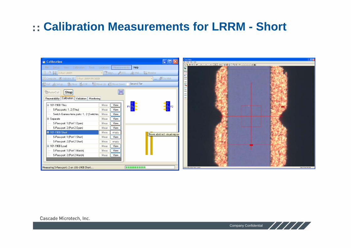
Calibration Measurements for LRRM - Short

Company Confidential
See It. Touch It. Measure It.
Calibration Measurements - Load
It is important that only 50 ohm loads are used for this part of the calibration

Company Confidential
See It. Touch It. Measure It.
Calibration – Computation and sending of error coefficients
Wincal applies the selected calibration to the measured data (typically we recommend LRRM) and error set is sent to the instrument

Company Confidential
See It. Touch It. Measure It.
Calibration - Validation
Following calibration a validation is carried out against a known standard. Typically this is an open whose capacitance is known by the probe pitch, but can be a golden dut whose characteristics are pre-measured and stored. For lrrm the open is the raw open measured during the cal and corrected by the calibration (post corrected)

Company Confidential
See It. Touch It. Measure It.
Wincal – Advanced reporting

Company Confidential
See It. Touch It. Measure It.
Wincal – Advanced reporting
Wincal can carry out advanced reporting to carry out post process mathmatics “on the fly” such as parasitic de-embedding, parameter conversion and subtaction, Masons gain etc.Multiple page views can be created for truly versatile reporting

Company Confidential
See It. Touch It. Measure It.
Wincal - Sequencing
Sequences allow the prober and external instrumentation to be controlled by Wincal for simple automated testing

Company Confidential
See It. Touch It. Measure It.
Wincal - Sequencing

Company Confidential
See It. Touch It. Measure It.
Wincal runs native on pna
No need for external laptop and gpib adaptorPNA Can be used to control external instrumentation with SequencingOnly 1 external monitor is required

Company Confidential
See It. Touch It. Measure It.
Calibration Verification
What defines a good calibration?• Ideally a reflection measurement after calibration should be 0.0dB• LRRM type calibration is self-consistent and will never look perfect as it will
show any errors as a magnitude on a reflection measurement• A guide would be to ensure that the magnitude of the reflection error is less
than 0.1dB for measurement to 67GHz and 0.2dB to 110GHz• Note this does not apply to an SOLT or SOL calibration as these are not self
consistent and will be forced to look like a perfect reflection standard- Independent standards will need to be measured for verification

Company Confidential
See It. Touch It. Measure It.
Independent Verification
As well as re-measuring the calibration standards, other verification standards can be measured to determine successful calibration
• These include open stubs and transmission lines• Open stubs and lines of varying lengths are found on the calibration
standards
Various lengths of transmission lines

Company Confidential
See It. Touch It. Measure It.
Calibration Verification Standards
• Unity Gain
• Negative Capacitance
-Due to wave propagation being faster in air than on the Alumna substrate
Reflect(probes in air)
-0.5
-0.4
-0.3
-0.2
-0.1
0.0
0.1
0.2
0.3
0.4
0.5
0 5 10 15 20 25 30 35 40
[dB]
[GHz]10 2050
10
2050
-10
-20-50
0.1 GHz
40.0 GHz

Company Confidential
See It. Touch It. Measure It.
Independent Verification Standards
Open stub
GROUND
GROUND
SIGNAL0.2 0.4 0.6 0.8 1 1.5 2 3 4 5 10 2050
0.2
0.4
0.6
0.8 11.5
2
3
4
5
10
2050
-0.2
-0.4
-0.6
-0.8 -1-1.5
-2
-3
-4
-5
-10
-20-50
0.1 GHz
40.0 GHz
-1.5
-1.0
-0.5
0.0
0 5 10 15 20 25 30 35 40
[dB]
[GHz]
• Linear Phase Lag
• 50ohm to stub Z miss-match
• Fringing C at stub open end

Company Confidential
See It. Touch It. Measure It.
Calibration Drift
WinCal XE Calibration software has a feature called monitoringMonitoring allows the user to capture calibrated reference data immediately after a calibration has been performed. At a later time, you can re-measure the previously-acquired references (by selecting Calibration>Monitor in the Calibration menu), compare the data to the reference data, and determine if any portion of the measurement system has changed. Measurements and structures used in calculating the monitoring data are listed in the Monitoring tab.

Design for testability

Company Confidential
See It. Touch It. Measure It.
Design for Testability
Do you want to test the device at wafer level?• If yes, you will need to have a pad layout which conforms with possible
probe configurations.How much money do you want to spend on probes?
• Complex designs may require an RF/Microwave probe card• Well designed circuits may be able to use existing probes
Do you want to automate die-to-die testing?• Can a wafer map be generated to step across a wafer?

Company Confidential
See It. Touch It. Measure It.
Think About Testing Before Design
RF Performance•Pad configuration (GS Vs GSG)•Probe pitch
Ability to Physically Probe•Pad size•Pad height •Distance between probes•Number of contacts per side
Calibration•Paths•Best calibration methods•De-embedding devices

Company Confidential
See It. Touch It. Measure It.
Pad Sizes
Recommended minimum pad is 80um x 80um for ACP Probes
Infinity Probe Allows 50um x 50um probing
Passivation height must be consideredPad height variation must not exceed 25um for ACP or 0.5um for Infinity

Company Confidential
See It. Touch It. Measure It.
Probe Configuration
Whenever possible use GSG• Use GSG above 10GHz
Probe pitch affects S-parameters• Use smallest practical pitch
- 1/50thλ of highest frequency for GS- 1/20thλ of highest frequency for GSG

Company Confidential
See It. Touch It. Measure It.
Device Pad Layout

Company Confidential
See It. Touch It. Measure It.
Probe Pad Positioning
RF probes should have more than 200um separation to avoid cross-talkAll pads must be on top surfaceAll grounds should be connected togetherAdjacent devices should be >500um away for mm-wave measurements (>250um for Infinity)
200um
>500um

Company Confidential
See It. Touch It. Measure It.
Maximum Probe Contacts
The maximum number of RF & DC contacts per side depends on the type of probe used to test the DUT
•Only 1 standard RF or DC series probe head can be mounted on each side
•A dual signal RF probe allows a GSSG/GSGSG probe on each side•A multi contact RF probe allows up to 3 RF contacts, or mixed RF
and DC on each side•RF probe cards allows many RF and DC contacts on any side (but
expensive if not in production)

Company Confidential
See It. Touch It. Measure It.
Calibration Repeatability
• LRRM automatic calibration is VERY repeatable
Wor
st c
ase
devi
atio
n
Frequency (GHz)
10 LRRM calibration verifications using NIST Verify software

Company Confidential
See It. Touch It. Measure It.
Pad Parasitic Removal
Conductive substrate increases parasitic reactance• Pad and interconnect capacitance and inductances become more
significant during device measurement- De-embedding of pads and interconnects is required
Limitations of Pad Parasitic Removal methods• The larger the pads and smaller the device, makes de-embedding
more difficult to achieve

Company Confidential
See It. Touch It. Measure It.
Measurement and De-embedding
Source + Substrate
DrainGate
Ground
Ground
Ground
Ground
SignalSignal
Eliminateparasiticeffects
through De-embedding
Ground
Ground
Signal
Reference plane
Ground
Ground
Signal
Referenceplane • After calibration,
the measurement reference plane is at the probe tip
• What is measured is the response of the device and the parasitics associated with the pads
Source + Substrate

Company Confidential
See It. Touch It. Measure It.
De-embedding and Verification Test Structures
OPEN SHORT
DUT THRU

Company Confidential
See It. Touch It. Measure It.
The parasitics of the OPEN consists only of parallel elements to the DUT
- More importance for high impedance devices
The parasitics of the SHORT consists only of series elements to the DUT
- More importance for high impedance devices
Use of Z and Y correction also helps eliminate residual cal errors
De-embedding from OPEN and SHORT
De-embedding dummy devices

Company Confidential
See It. Touch It. Measure It.
De-embedding Techniques
• Open and Short ‘dummy’devices need to be measured
• S-parameters are transformed to Y, Z-parameters
• The dummy devices can be subtracted from the actual device
• The resulting Y, Z-parameters can be transformed and displayed

Company Confidential
See It. Touch It. Measure It.
Thankyou for [email protected]
+44 1926 403900 – office general tel