MANKAR 2 MANKAR For the undiluted application of Roundup® products (Glyphosate) The instructions on...
12
09.03.2009 1 OPERATING INSTRUCTIONS MANKAR Modelle: MANKAR-P 30-50 Flex, MANKAR-P 50 MANKAR-P 60-80, MANKAR-P 70-110 MANKAR-GP 60-80 , MANKAR-GP 70-110 ULV- Applicator for weed control in areas of specialised cultivation such as nurseries, orchards and vineyards, ornamental plant and vegetable gardens, as well as agricultural, forestry, communal and non-cultivated lands. The unit has been developed for the undiluted application of ROUNDUP products (Glyphosate). Important: Before application, carefully read the usage instructions for the unit and the plant protective agent! Observe safety instructions! For questions regarding plant protective agents, consult the manufacturer! Observe the requirements and regional regulations for the use of herbicides and, if necessary, obtain approval from the responsible authorities (e.g. environmental conservation agency)! Application is to be performed only by a competent user. Remarks about usage of the unit: Settings: This system is not suitable for the application of water. Use herbicides for testing the spray action and calibration of the flow rate. Usage: Position the spray hood directly above the ground – if the spray hood is held too high, the danger of spray driftage exists. Cleaning: Do not clean the unit with a high-pressure spray or an intense water jet spray. Noise emission from the unit equates to less than 70 dB(A). Manufacturer: Mantis ULV-Sprühgeräte GmbH Germany 21502 Geesthacht, Vierlander Str. 11 a Telephone +49(0)4152-8459-0, FAX +49(0)4152-8459-11 Web: www.mantis-ulv.eu Email: [email protected]
Transcript of MANKAR 2 MANKAR For the undiluted application of Roundup® products (Glyphosate) The instructions on...

09.03.2009 1
OPERATING INSTRUCTIONSMANKAR
Modelle: MANKAR-P 30-50 Flex, MANKAR-P 50
MANKAR-P 60-80, MANKAR-P 70-110
MANKAR-GP 60-80 , MANKAR-GP 70-110
ULV- Applicator for weed control
in areas of specialised cultivation such as nurseries, orchards and
vineyards, ornamental plant and vegetable gardens, as well as
agricultural, forestry, communal and non-cultivated lands.
The unit has been developed for the undiluted
application of ROUNDUP products (Glyphosate).
Important:Before application, carefully read the usage instructions for the unit and the plant protective agent!
Observe safety instructions!
For questions regarding plant protective agents, consult the manufacturer!
Observe the requirements and regional regulations for the use of herbicides and, if necessary,
obtain approval from the responsible authorities (e.g. environmental conservation agency)!
Application is to be performed only by a competent user.
Remarks about usage of the unit:Settings: This system is not suitable for the application of water.
Use herbicides for testing the spray action and calibration of the flow rate.
Usage: Position the spray hood directly above the ground –
if the spray hood is held too high, the danger of spray driftage exists.
Cleaning: Do not clean the unit with a high-pressure spray or an intense water jet spray.
Noise emission from the unit equates to less than 70 dB(A).
Manufacturer:
Mantis ULV-Sprühgeräte GmbHGermany 21502 Geesthacht, Vierlander Str. 11 a
Telephone +49(0)4152-8459-0, FAX +49(0)4152-8459-11
Web: www.mantis-ulv.eu Email: [email protected]

29.06.2012 2
MANKAR For the undiluted application of Roundup
® products (Glyphosate)
The instructions on this page are valid for all MANKAR applicator units. Details regarding assembly, use and replacement
parts are provided on the following pages:
MANKAR-P 30-50 FLEX, MANKAR-P 50: Pages 4-5
MANKAR-P 60-80, MANKAR-P 70-110: Pages 6-7
MANKAR-GP 60-80, MANKAR-GP 70-110: Pages 8-9
Intended usage: Weed control in areas of specialised cultivation such as nurseries, orchards and vineyards, ornamental plant and
vegetable gardens, as well as agricultural, forestry, communal and non-cultivated lands.
Before application, carefully read the usage instructions for the applicator unit and pesticides.
Observe safety instructions.
For questions regarding pesticides, consult the manufacturer!
Observe the requirements and regional regulations for the use of herbicides.
Noise emission from the unit equates to less than 70 dB (A).
Protective measures
Observe the remarks in the pesticide usage instructions
regarding user safety and wear recommended body
protection. Wear protective gloves when filling the chemical
substance.
Do not eat, smoke or drink while working with pesticides.
Avoid chemical spillage without fail. Thoroughly clean hands
and face after completion of work.
Thoroughly clean and dry the unit immediately following its
usage. Never use the mouth to blow out nozzles or other
small parts!
Keep pesticide applicators and chemical substances away from children.
Assembly and preparation for initial application Unit assembly is described for the individual models.
Prior to initial deployment of the applicator unit, charge the battery for at least 16 hours.
Attention! Follow the sequence without fail:
1. Depress the switch in the powerpack; the lamp illuminates.
2. Insert the plug jack into the charger socket.
3. Insert the charging unit into the 110-230 volt power outlet.
The battery has reached its full voltage capacity after approx. 16 hours charging time. When the charging process is
complete, first unplug the charging unit from the 230 volt power outlet, and then remove the applicator unit plug from the
charger socket.
Spray duration when operating one segmental atomiser
with one 6 V-7 Ah battery approx. 16 hours
Spray duration when operating two segmental atomisers
with one 6 V-7 Ah battery approx. 8 hours
A powerpack with two batteries can be installed in order to double the unit's operating duration.
Art. No.: 100467
It must be noted that, with this powerpack option, the required charging time will also double.
The spray width should subsequently be checked - ideally with a piece of cardboard laid out on the ground - and the flow rate
adjusted (see below for details).
The battery should be recharged immediately after using the applicator unit.
General remarks regarding applicator unit function and deployment
Pesticides: This applicator unit was originally designed for the undiluted application of Roundup products (Glyphosate).
Practical experience has shown, however, that other herbicides can also be deployed in conjunction with this technology.
Considering the many products on the market with their differing formulations, it is not possible to provide a complete list with
application rate recommendations. Specifications for adjusting the unit listed on the following pages relate to the usage of
Roundup UltraMax (Glyphosate 450 gr/ltr). In general, all products with a comparable viscosity are suitable. If it is intended to
use a product other than Roundup UltraMax, its application should be first tested over a small area on a trial basis. Usage
instructions for the chosen herbicide should be observed in every case, along with local requirements.

20.03.2009 3
Applicator unit function: Segmental atomisers are driven by means of a rechargeable battery. Metering on all the units
mentioned is path-dependent and takes place by means of a wheel driven pump. Droplets are formed by the centrifugal force
of the rotating atomiser. The droplets are discharged downwards by the segmental atomiser through a continuously variable,
adjustable segment. Residual chemical in the tank not intended for application is approx. 50 ml. This residual fluid can be
refilled back into the original herbicide container.
Checking applicator unit function: Chemical solutions may flow quicker or slower due to temperature fluctuations, for which
reason the flow rates in the metering table should be checked and corrected as necessary. This system is not suitable for the
application of water. Please use herbicides at all times for testing the spray process and calibrating the flow rate. Check the
rotating atomiser on a daily basis for cleanliness and free turning motion. Check the output volume from time to time
throughout the season.
Deployment of the applicator unit: Adjust the height of the spray hood in such a manner that it is as close to the ground as
possible - if it is set too high, the risk of spray driftage exists. During operation, chemical fluid will collect in the segmental
atomiser reservoir and will continue to drip for approx. 30 seconds after the shut-off valve has been closed if the unit is tilted.
In order to avoid damage to cultivated plants due to dripping, we recommend closing the shut-off valve at the end of a row, for
example, then folding the spray hood upwards and waiting approx. 30 seconds until the reservoir has emptied.
Spray width
• Place an underlay (cardboard or paper) on the ground and prop up the unit on stands.
• Actuate the switch button on the powerpack while simultaneously turning the wheel and appraising the spray width
obtained, initially at one location. The spray width must be set in such a manner that the droplets are discharged over the
entire width of the spray hood. The optimal spray width under standard operating conditions is set by the manufacturer.
• Compensate for deviations is possible by loosening screw (F) and sliding the width adjustment on the atomiser
(see drawing).
• Further details regarding operating width adjustment can be found on the respective pages for the individual applicator
units.
Cleaning
Do not clean the applicator unit with a high-pressure sprayer or with an intense water jet spray.
Cleaning during the season: During short work breaks (a few hours), herbicide can remain
in the system as long as the shut-off valve remains closed. After work completion: before
cleaning, refill the chemical solution into its original container. Open the shut-off and set the
metering pump to maximum. Fill the chemical tank halfway with water, then, with the unit
positioned, turn the wheel smoothly 50 x and allow the fluid to drain into a collector tank or,
operating the unit for approx. 100 m, apply the cleaning fluid to the already treated surface.
Remove any remaining water from the tank and turn the wheel 50 x once again until the
system is completely empty.
Cleaning at the end of the season: Rinse the unit with warm water as described above. Additionally: Unscrew filter and
clean screen as necessary. The spray hood and the atomiser housing can be cleaned with a moist cloth, except the atomiser
disc in order to avoid damage. With heavy contamination, the atomiser housing should be unscrewed to remove
contaminants and plant parts. Connect the unit to the charging device (see below).
Charging the applicator unit and care of the accumulator
The applicator unit is outfitted with an automatic charging device. Trickle charging is possible.
In order to recharge a completely empty battery up to full capacity, approx. 16 hours charging time is required.
The battery should be recharged immediately after usage.
Battery charging Minimum charging time Time intervalFully discharged 16 hrs. immediately
Short-term usage 6 hrs. immediately
Storage without usage ( 2 hrs. 1 x per month ) or permanent charge
With a fully loaded battery, units with one atomiser can be deployed for 16 hours, while units with 2 atomisers can be
deployed for approx. 8 hours.
INCORRECT
CORRECT

20.03.2009 4
Assembly
1. Screw the applicator unit support stand (A) together with
the stand foot (B).
2. Screw the spray hood together with the height adjustment
(K) and the unit support beam (C).
3. Connect the electrical plug connectors (D) together.
4. Screw the flow rate control (E) onto the unit support beam
(C).
5. Screw the handle bar (G) together with the handle bar
extension (F)
6. Insert the handle bar extension (F) into the unit support
beam (C) and tighten securely.
7. Slide the powerpack (H) into the designated bracket on
the unit support beam (C) and tighten securely.
8. Insert the phone jack (I) into the plug socket on the
powerpack (H).
9. Attach the hose (J) onto the lower side of the flow rate
control (E).
Metering table
Roundup UltraMax application rate at 20 °C
Roundup
UltraMax
Metering
adjustment
knob
position
Required output volume
in ml per atomiser
with 50 wheel revolutions
2 l/ha
3 l/ha
E
H
approx. 6.3
approx. 9.5
Checking the output volume
1. Place an underlay (e.g. cardboard or paper) on the
ground and prop up the unit on stands.
2. Fill the chemical tank with herbicide - undiluted.
3. Remove the hose from the lower side of the flow rate
control and place a measuring cup underneath.
4. Open the shut-off valve, initially setting the metering
adjustment knob to the maximum flow rate and
simultaneously turning the wheel; wait until the
chemical solution is evenly applied.
5. Set the chemical solution volume according to the
output table.
6. Volume calibration: Collect the chemical solution from
50 wheel revolutions into a measuring cup. If the
desired volume is not reached, set a larger or a
smaller volume with the pump metering adjustment
knob.
7. Perform volume calibration again.
8. Reconnect the hose on the lower side of the flow rate
control.
9. The unit is now ready for deployment.
Maximum allowable wheel pressure 3.5 bar
Shut-off valve position closed
MANKAR-P 30-50 FLEX
MANKAR-P 50
Spray hood 30-50 FLEX

06.02.2014 5
Pump drive
Item Part No. Description
102360 MANKAR-P 30-50 FLEX
101093 MANKAR-P 50
1 100349 Rubber hand grip for MANKAR
2 101272 Handle bar for MANKAR
4 101273 Handle bar VA extension for MANKAR-P
5 100459 Powerpack compl. 1 battery 6V-7 Ah, for MANKAR
6 100368 Star grip screw, 8 mm x 25
7 100387 Phone jack with cable, 1050mm MANKAR
8 101274 Unit support beam VA for MANKAR-P and -110P
9 101275 Pump carrier VA incl. stand for MANKAR-P -110P
10 100402 Wheel 400 x 100 mm, pneumatic tyre
11 100492 Metering pump MAFEX-3, capacity 2 - 20 ml/min
12 - - - - - - Pressure hose 4 x 2 mm
13 100351 Spray hood 50 cm wide for MANKAR-P and MANTRA
15 100434 Tank 1 L, MANKAR, without lid
16 100441 Tank lid, 1 L with hole for MANKAR units
17 100390 Ball valve 1/4" i/i
18 - - - - - - Pressure hose 4 x 2 mm
19 101276 Height adjustment for MANKAR-P with tank holder
20 100397 Flow rate controler, complete for MANKAR without holder
22 100392 Pump threaded sleeve for MAFEX / MANKAR pumps
23 100389 Clamping bush for wheel axle/pump
25 100141 O-ring 4,47 x 1,78 mm for pistons, MAFEX/MANKAR pumps
26 100393 Cardan shaft, MS, for MANKAR units
27 100377 Retaining collar 20.5 mm for wheel axle MANKAR and mounted units
29 100457 Adjusting Washer 20x28x1 mm for pump drive
30 100394 Retaining ring A 20 for pump carrier MANKAR / FLEXOMANT
31 101720 Cardan shaft carrier
100375 Entrainer disk for MANKAR units
32 102248 Spray hood 30-50cm Flex compl. with atomiser and height adjustment, MANKAR-P
33 102327 Spray hood 30-50 cm, right chamber, VA
34 102326 Spray hood 30-50cm, chamber-left
35 102394 Rubber curtain for MANKAR-30-50
11 11 11
9
10

20.03.2009 6
Assembly
1. Screw the applicator unit support stand (A) together with
the stand foot (B).
2. Screw the spray hood together with the height
adjustment (B) and the unit support beam (C).
3. Connect the electrical plug connectors (D) together.
4. Screw the flow rate control (E) onto the unit support
beam (C).
5. Screw the handle bar (G) together with the handle bar
extension (F)
6. Insert the handle bar extension (F) into the unit support
beam (C) and tighten securely.
7. Slide the powerpack (H) into the designated bracket on
the unit support beam (C) and tighten securely.
8. Insert the phone jack (I) into the plug socket on the
powerpack (H).
9. Attach the hose (J) onto the lower side of the flow rate
control (E).
Metering tableRoundup UltraMax application rate 2 l/ha at 20 °C
Spray width
in cm
Metering
adjustment
knob position
Required output volume
in ml per atomiser
with 50 wheel revolutions
60
70
80
90
100
110
A
B
C
D
E
F
approx. 3.8
approx. 4.4
approx. 5.0
approx. 5.6
approx. 6.3
approx. 6.9
Calculating divergent application rates:
Factor x Spray width in cm =
Required volume per atomiser
in ml with 50 wheel revolutions
Factor for 1 l/ha: 0,031
Factor for 2 l/ha: 0,063
Factor for 3 l/ha: 0,094
Adjusting the spray width
a) Loosen the spray hood screws in the elongated holes
on the upper side of the sheet metal skirt and unscrew
the screws from the front side of the sheet metal skirt.
b) Adjust the segmental rotation atomiser to the desired
width (see page 3 of the Operating Instructions).
c) Retighten the screws.
Checking the output volume
1. Place an underlay (e.g. cardboard or paper) on the
ground and prop up the unit on stands.
2. Fill the chemical tank with herbicide - undiluted.
3. Remove the hose from the lower side of the flow rate
control and place a measuring cup underneath.
4. Open the shut-off valve, initially setting the metering
adjustment knob to the maximum flow rate and
simultaneously turning the wheel; wait until the
chemical solution is evenly applied.
5. Set the chemical solution volume according to the
output table.
6. Volume calibration: Collect the chemical solution from
50 wheel revolutions into a measuring cup. If the
desired volume is not reached, set a larger or a
smaller volume with the pump metering adjustment
knob.
7. Perform volume calibration again.
8. Reconnect the hose on the lower side of the flow rate
control.
9. The unit is now ready for deployment.
Maximum allowable wheel pressure 3.5 bar
Shut-off valve position closed
MANKAR-P 60-80
MANKAR-P 70-110
Spray hood 60-80

Part Art. No. Designation
101094 MANKAR-P 70-110
102391 MANKAR-P 60-80
1 100349 Rubber hand grip for MANKAR
2 101272 Handle bar VA for MANKAR-P VA, -110P VA
4 101273 Handle bar extension VA for MANKAR-P VA, -110P VA
5 100459 Powerpack with 1 battery, 6 V - 7 Ah, for MANKAR-P,-110P
6 100368 Star knob screw M 8 x 25 mm
7 100387 Phone jack with cable, 1050 mm, MANKAR
8 101274 Unit support beam VA for MANKAR-P VA and -110 P VA
9 101275 Pump carrier VA incl. stand for MANKAR-P VA, -110P VA
10 100402 Wheel 400 x 100 mm, pneumatic-tyred
11 100522 Metering pump MANKAR-3, capacity 5 - 10 ml/min
12 - - - - - - Pressure hose 4 x 2 mmPressure hose 4 x 2 mm
13 100388 Cable, Atomiser cable, Mankar/Flex/Var/Mafex
14 100363 Sheet metal skirt, 600mm for spray hood 70 - 110 cm
15 100400 Spray hood, split, 25 cm wide, left for spray hood 70 - 110 cm
100426 Spray hood, split, 25 cm wide, right for spray hood 70 - 110 cm
17 100434 Tank 1 L, MANKAR, without lid
18 100441 Tank lid, 1 L with hole for MANKAR units
19 100390 Ball valve 1/4" i/i
20 101276 Height adjustment for MANKAR-P, with tank holder
21 100397 Flow rate controller, complete, for all MANKAR units, without holder
22 100415 bracket for 2 flow rate controllers, MANKAR-110 P
23 100381 Clamping strip for rubber skirt, spray hood 70 - 110 cm, MANKAR
24 100380 Rubber skirt for spray hood MANKAR-110 P, -110 GP
25 100433 Stands for MANKAR units
26 101436 Spray hood 60-80 cm complete for MANKAR P with 2 atomisers, height adjustment with tank holder
27 102551 Spray hood, 30cm with guide rail, left for spray hood 60-80cm
28 102552 Spray hood, 30cm with guide rail, right for spray hood 60-80cm
Pump drive, see
page 5
20.03.2009 7
20.03.2009 8
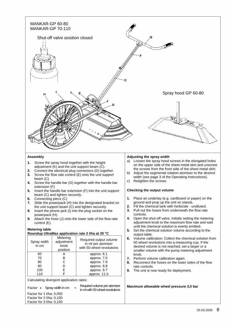
Assembly
1. Screw the spray hood together with the height
adjustment (K) and the unit support beam (C).
2. Connect the electrical plug connectors (D) together.
3. Screw the flow rate control (E) onto the unit support
beam (C).
4. Screw the handle bar (G) together with the handle bar
extension (F)
5. Insert the handle bar extension (F) into the unit support
beam (C) and tighten securely.
6. Connecting piece (C)
7. Slide the powerpack (H) into the designated bracket on
the unit support beam (C) and tighten securely.
8. Insert the phone jack (I) into the plug socket on the
powerpack (H).
9. Attach the hose (J) onto the lower side of the flow rate
control (E).
Metering tableRoundup UltraMax application rate 2 l/ha at 20 °C
Spray width
in cm
Metering
adjustment
knob
position
Required output volume
in ml per atomiser
with 50 wheel revolutions
60
70
80
90
100
110
A
B
C
D
E
F
approx. 6.1
approx. 7.0
approx. 7.9
approx. 8.8
approx. 9.7
approx. 11.0
Calculating divergent application rates:
Factor x Spray width in cm =
Required volume per atomiser
in ml with 50 wheel revolutions
Factor for 1 l/ha: 0,050
Factor for 2 l/ha: 0,100
Factor for 3 l/ha: 0,150
Adjusting the spray width
a) Loosen the spray hood screws in the elongated holes
on the upper side of the sheet metal skirt and unscrew
the screws from the front side of the sheet metal skirt.
b) Adjust the segmental rotation atomiser to the desired
width (see page 3 of the Operating Instructions).
c) Retighten the screws.
Checking the output volume
1. Place an underlay (e.g. cardboard or paper) on the
ground and prop up the unit on stands.
2. Fill the chemical tank with herbicide - undiluted.
3. Pull out the hoses from underneath the flow rate
controls.
4. Open the shut-off valve, initially setting the metering
adjustment knob to the maximum flow rate and wait
until the chemical solution is evenly emitted.
5. Set the chemical solution volume according to the
output table.
6. Volume calibration: Collect the chemical solution from
50 wheel revolutions into a measuring cup. If the
desired volume is not reached, set a larger or a
smaller volume with the pump metering adjustment
knob.
7. Perform volume calibration again.
8. Reconnect the hoses on the lower sides of the flow
rate controls.
9. The unit is now ready for deployment.
Maximum allowable wheel pressure 3,0 bar
Shut-off valve position closed
Spray hood GP 60-80
MANKAR-GP 60-80
MANKAR-GP 70-110

Part Art. No. Designation
102490 MANKAR-GP 60-80
100526 MANKAR-GP 70-110
1 100349 Rubber hand grip for MANKAR
2 + 3 101272 Handle bar for MANKAR
4 100419 Handle bar extension, MANKAR GP
5 100990 Hexagon screw M 8 x 20 mm stainless steel
6 100429 Connection for handle bar extension MANKAR GP
7 100397 Flow rate controller, complete, for all MANKAR units, without holder
8 - - - - - - Pressure hose 4 x 2 mmPressure hose 4 x 2 mm
9 100388 Cable, Atomiser cable, Mankar/Flex/Var/Mafex
10 100363 Sheet metal skirt, 600mm for spray hood 70 - 110 cm
11 100400 Spray hood, split, 25 cm wide, left for spray hood 70 - 110 cm
100426 Spray hood, split, 25 cm wide, right for spray hood 70 - 110 cm
12 100390 Ball valve 1/4" i/i
13 100441 Tank lid, 1 L with hole for MANKAR units
14 102589 Tank holder for MANKAR GP
15 100434 Tank 1 L, MANKAR, without lid
16 100395 Wheel with bearing bush, 560 mm for MANKAR GP
18 100556 Pump carrier for MANKAR-110 GP
19 100558 criss beam with attachment bracket for powerpack, MANKAR GP
20 100459 Powerpack with 1 battery, 6 V - 7 Ah, for MANKAR
21 100379 Strain relief cover for spray hood 70-110 cm
22 100440 Holders for 2 flow rate controls, MANKAR GP
23 102491 Attachment bracket for spray hood MANKAR GP
24 100360 Height adjustment for spray hood MANKAR GP
25 100381 Clamping strip for rubber skirt, spray hood 70 - 110 cm, MANKAR
26 100380 Rubber skirt for spray hood 70-110, MANKAR
27 100527 Metering pump MANKAR-3, capacity 5 - 12 ml/min for MANKAR-110 GP
28 100392 Pump threaded sleeve for MAFEX / MANKAR pumps
29 100377 Retaining collar 20.5 mm for wheel axle, MANKAR and mounted units
30 100393 Cardan shaft, MS, for MANKAR units
31 100457 Adjusting washer 20x28x1 mm for pump drive
32 100394 Retaining ring A 20 for pump carrier, MANKAR / FLEXOMANT
33 100375 entrainer disk for MANKAR units
34 101718 angle for entrainer disk, MANKAR GP
35 101096 Spray hood 60-80 cm complete for MANKAR-110 GP with 2 atomisers and height adjustment
36 102551 Spray hood, 30cm with guide rail, left for spray hood 60-80cm
37 102552 Spray hood, 30cm with guide rail, right for spray hood 60-80cm
Pump drive
20.03.2009 9

20.03.2009 10
PartArt. No. Designation Part Art. No. Designation
100459 Powerpack with 1 battery, 6 V - 7 Ah, for MANKAR-P models
100320 Atomiser for MANKAR 102312 Powerpack with 1 battery, 6 V - 7 Ah, for MANKAR-GP models
1 102417 Motor module for segmental atomiser MANKAR 1 100469 Powerpack housing
2 100478 Atomiser disc for segmental atomiser 2 100461 Clamping rail, round milled for MANKAR P powerpack
3 101996 Segment module for segmental atomiser 2a 101858 Clamping rail, round milled for MANKAR GP powerpack
3 100450 Battery 6 V - 7 Ah
4-8 101565 Cover for MANKAR powerpack, assembled
4 100693 Low voltage plug adapter
5 100464 Switch, green illumination, square, for powerpack and control box
6 100365 Fuse holder, complete for MINI-MANTRA / MANKAR FLEXOMANT / …
7 100730 Glass fuse 5X20 T 3.15A
8 100466 Powerpack cover
PartArt. No. Designation Part Art. No. Designation
100522 Metering pump MANKAR-3, capacity 5 - 10 ml/min 100492 Metering pump MAFEX-3, capacity 2 - 20 ml/min
1 100528 Housing, pump housing, MS for MANKAR 1 100493 Housing, pump housing, MS for MAFEX
2 102209 Rotor-3, MS for piston pumps MAFEX / MANKAR 2 102209 Rotor-3, MS for piston pumps MAFEX / MANKAR
3 102373 Sealing set for MANKAR/MAFEX-3 metering pump 3 102373 Sealing set for MANKAR/MAFEX-3 metering pump
4 101626 Repair set, MANKAR metering pump, pressure plate/wobble plate 4 102436 Repair set, MAFEX metering pump, pressure plate/wobble plate
5 102429 Repair set, MANKAR metering pump, metering adjustment knob/selector disc 5 102437 Repair set, MAFEX metering pump, metering adjustment knob/selector disc
6 100534 Cover for piston pump 6 100534 Cover for piston pump
2 1
3
4
5
6
3
1
2
2 1
3
4
5
6
For units with
two atomisers
For units with
one atomiser
20.03.2009 11
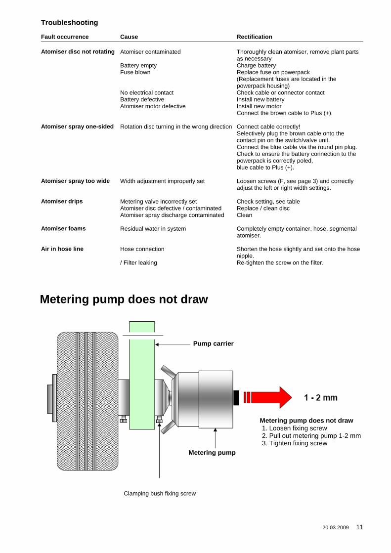
Troubleshooting
Fault occurrence Cause Rectification
Atomiser disc not rotating Atomiser contaminated Thoroughly clean atomiser, remove plant parts
as necessary
Battery empty Charge battery
Fuse blown Replace fuse on powerpack
(Replacement fuses are located in the
powerpack housing)
No electrical contact Check cable or connector contact
Battery defective Install new battery
Atomiser motor defective Install new motor
Connect the brown cable to Plus (+).
Atomiser spray one-sided Rotation disc turning in the wrong direction Connect cable correctly!
Selectively plug the brown cable onto the
contact pin on the switch/valve unit.
Connect the blue cable via the round pin plug.
Check to ensure the battery connection to the
powerpack is correctly poled,
blue cable to Plus (+).
Atomiser spray too wide Width adjustment improperly set Loosen screws (F, see page 3) and correctly
adjust the left or right width settings.
Atomiser drips Metering valve incorrectly set Check setting, see table
Atomiser disc defective / contaminated Replace / clean disc
Atomiser spray discharge contaminated Clean
Atomiser foams Residual water in system Completely empty container, hose, segmental
atomiser.
Air in hose line Hose connection Shorten the hose slightly and set onto the hose
nipple.
/ Filter leaking Re-tighten the screw on the filter.
Clamping bush fixing screw
Metering pump does not draw
Pump carrier
Metering pump
Metering pump does not draw1. Loosen fixing screw
2. Pull out metering pump 1-2 mm
3. Tighten fixing screw

06.02.2014 12
GUARANTEE
I. If the purchase is a commercial transaction for both sides, the Customer must examine the goods
immediately on receipt, as far as this is possible during the regular course of business and if there
is a defect, inform the Vendor immediately.
II. If the Customer does not make a complaint, the goods are considered approved, unless there is a
defect, which was not visible during the examination. Furthermore §§ 377 ff. HGB applies.
III. The Vendor may choose to eliminate the defects or deliver an item free of defects, (rectification of
defects). If the rectification of defects fails, the Customer has the right to choose to either demand
a reduction in price or to withdraw from the contract.
IV. Further claims from the Customer, in particular due to consequential damage caused by a defect
are in principle disqualified. This does not apply in cases of intent, gross negligence or breaches
of contract by the Vendor as well as in cases of injury to life, body or health. The right of the
Customer to withdraw from the contract remains unaffected.
V. Warranty claims lapse after 24 months, respectively after 12 months in case of commercial use of
the goods. The limitation period begins at delivery. The guarantee expires, if the delivered goods
change or are handled incorrectly.
VI. The Vendor is not responsible for material defects on deliveries, which he sources from third
parties and forwards unchanged to the Customer. Responsibility in the case of intent or
negligence remains unaffected. The preceding regulations do not imply a change to the burden of
proof to the disadvantage of the Customer.
VII. Claims for defects do not only exist in cases of negligible deviations from the agreed properties
and conditions or only in negligible impairment of usefulness.
VIII. Necessary expenses for the purpose of the rectifying defects are to be paid by the Customer, if
they increase due to delivery to a different place than the place of business of the Customer,
unless the transport corresponds to its intended use.
EG-Declaration of conformity
Council Directive 2006/42/EG
Mantis ULV-Sprühgeräte GmbH, Vierlander Straße 11 a, 21502 Geesthacht declare under our sole
responsibility that the following products are in conformity with the provisions of the following Council
Directive: 2006/42/EG
Typ MANKAR-ONE, MANKAR-TWO
Typ MANTRA, MINI-MANTRA / PLUS, MICRO-MANTRA, MICRO-VASO, MANKAR HQ
Typ FLEXOMANT-1W, FLEXOMANT-2W, FLEXOMANT-3W, FLEXOMANT-4W,
FLEXOMANT-PLUS, VARIMANT-1, VARIMANT-2, VARIMANT-4 PLUS,
VARIMANT-WINNER-TOP, VARIMANT-WINNER-UNO
Typ MAFEX
Typ ROFA
Hiske Weissmann
Managing Director
Geesthacht January 2015
_______________________ _________________________________
(Place and date of signature) (Name, title and signature)