2 HYDRAULIC ENGINEERING BASIC KNOWLEDGE OPEN-CHANNEL … · Uniform discharge in a rectangular...
16
FREQUENTLY USED FORMULA SYMBOLS 69 E specific energy ∆E loss of specific energy h discharge depth h c critical depth h d downstream water discharge depth h o weir head h u upstream water discharge depth J energy grade line Q discharge v flow velocity W height of weir HYDRAULIC ENGINEERING BASIC KNOWLEDGE OPEN-CHANNEL FLOW Consistent with most textbooks, the GUNT experimental flumes teach the fundamentals of open-channel flow using an experimental flume with rectangular cross- section. In the first part of this section we present the basics principles of open- channel flow. Parallel to this, we show how certain issues and phenomena can be implemented by experiment. In principle, these explanations apply to all GUNT experimental flumes and their accessories. In nature, watercourses represent “open-channel flow”. For centuries, humans have been making structural interventions to watercourses: irrigation systems, flood protec- tion and utilisation of rivers for navigation and power generation. Famous examples are ancient water systems (aqueducts) or agricultural irrigation channels extending over very large distances: the “Levada” in Portugal (top). Basic principles of open-channel flow hydraulic radius, wetted perimeter, typical flume profiles 70 Uniform discharge in a rectangular flume flow formulae 72 Steady discharge continuity equation Bernoulli’s equation specific energy 73 Non-uniform discharge in a rectangular flume flow transition specific energy diagram specific force diagram 74 Determining the loss of specific energy in a hydraulic jump 76 Froude number and critical discharge momentary and permanent disturbance hydraulic jump at different Froude numbers 77 79 Positive and negative surges in open channels 80 Energy dissipation stilling basin 82 Control structures Flow over weirs over fall condition at the weir flow over fixed weirs overfall types calculation of discharge after Poleni ogee-crested weirs sharp-crested weirs broad-crested weirs siphon weir gates 84 84 85 86 86 87 88 89 90 91 Culvert 92 Local losses in flumes piers 93 Methods of discharge measurement flow-measuring flumes measuring weirs 94 95 T ransient flow: flow-induced vibrations vibrating piles 96 Sediment transport bed-load transport 97 T ransient flow: waves 98 Contents 2 gunt
Transcript of 2 HYDRAULIC ENGINEERING BASIC KNOWLEDGE OPEN-CHANNEL … · Uniform discharge in a rectangular...

FREQUENTLY USED FORMULA SYMBOLS
69
E specific energy
∆E loss of specific energy
h discharge depth
hc critical depth
hd downstream water discharge depth
ho weir head
hu upstream water discharge depth
J energy grade line
Q discharge
v flow velocity
W height of weir
HYDRAULIC ENGINEERING BASIC KNOWLEDGE OPEN-CHANNEL FLOW
Consistent with most textbooks, the GUNT experimental flumes teach the fundamentals of open-channel flow using an experimental flume with rectangular cross-section.
In the first part of this section we present the basics principles of open-channel flow. Parallel to this, we show how certain issues and phenomena can be implemented by experiment. In principle, these explanations apply to all GUNT experimental flumes and their accessories.
In nature, watercourses represent “open-channel flow”. For centuries, humans have been making structural interventions to watercourses: irrigation systems, flood protec-tion and utilisation of rivers for navigation and power generation.
Famous examples are ancient water systems (aqueducts) or agricultural irrigation channels extending over very large distances: the “Levada” in Portugal (top).
Basic principles of open-channel flowhydraulic radius, wetted perimeter, typical flume profiles
70
Uniform discharge in a rectangular flumeflow formulae
72
Steady dischargecontinuity equationBernoulli’s equationspecific energy
73
Non-uniform discharge in a rectangular flumeflow transitionspecific energy diagramspecific force diagram
74
Determining the loss of specific energy in a hydraulic jump 76
Froude number and critical dischargemomentary and permanent disturbancehydraulic jump at different Froude numbers
77
79
Positive and negative surges in open channels 80
Energy dissipationstilling basin
82
Control structuresFlow over weirs
overfall condition at the weirflow over fixed weirsoverfall typescalculation of discharge after Poleni
ogee-crested weirssharp-crested weirsbroad-crested weirssiphon weirgates
84
848586868788899091
Culvert 92
Local losses in flumespiers
93
Methods of discharge measurementflow-measuring flumesmeasuring weirs
94
95
Transient flow: flow-induced vibrationsvibrating piles
96
Sediment transportbed-load transport
97
Transient flow: waves 98
Contents
2 gunt

Rectangle, trapezoid with 60° angles, triangle; h discharge depth, b flume width
HM 162.77 Flume Bottom with Pebble Stones
71
HYDRAULIC ENGINEERING BASIC KNOWLEDGE OPEN-CHANNEL FLOW
Basic principles of open-channel flow
Open-channel flows are widely spread. Typical examples include rivers and canals, drainage channels, gutters, water rides at amusement parks or sewerage. The driv-ing force of this normally turbulent flow is gravity. Open-channel flows are characterised by their free surface. Compared to pipe flows, open-channel flows have one more degree of freedom as a result of the free surface.
There are essentially two types of open-channel flow:
uniform flow (the discharge depth (water depth) remains equal; acceleration = deceleration)
non-uniform flow (the discharge depth is changed by acceleration or deceleration)
The discharge can be either subcritical, critical or supercritical.
1 rapidly varied discharge under a gate,2 gradually varied discharge,3 hydraulic jump (rapidly varied),4 weir overfall (rapidly varied),5 gradually varied discharge,6 non-uniform flow at a change of slope
In most cases an approximation of the respective cross-section of an open-channel flow can be illustrated with only a few geometric profiles. Circular, semi-circular, square, trapezoidal and combinations of these profiles are perfectly suited to making the flume easier to model and calculate mathematically. It is often important to determine the discharge Q and the discharge depth h at defined locations. Typical variables for calculations are the flow area A (or the area of flow), the wetted perimeter P and the hydraulic radius R.
In the case of a rectangular cross-section, these vari-ables are defined as follows:
flow area A = bh
wetted perimeter P = b+2h
hydraulic radius R = A/P = bh/(b+2h) In wide, shallow flumes the hydraulic radius R therefore corresponds to the discharge depth h.
In the case of artificial flumes, such as ducts, the hydrauli-cally efficient profile is an important variable – an optimum profile design saves materials and costs:
given discharge Q + energy grade line J: determine minimum flow area A
given discharge Q + flow area A: determine minimum energy grade line J.
GUNT experimental flumes have a rectangular cross-sec-tion. In addition to being able to install different models, they also allow the user to change the slope and the flume bottom, affecting the surface and roughness. A large number of experiments on uniform and non-uniform open-channel flow, including measurement of flow velocity v and discharge depth h, is possible.
Optimal hydraulic flume cross-section
In the case of the smallest wetted perimeter, based on the given area, we refer to the optimal hydraulic cross-section.
Typical flume profiles
2 gunt

Uniform discharge in a rectangular flume Steady discharge
73
In uniform open-channel flow the discharge depth h remains equal, i.e. parallel to the bottom. This also means that the flow velocity v remains constant.
The discharge depth h can also be described as a pres-sure head (a component of the specific energy). These energy heads are often applied in the form of what are known as grade lines. In the energy grade line J the most
significant component in many cases is the discharge depth h. In uniform open-channel flow the energy grade line J is equal to the bottom slope JS and thus equal to the discharge depth h. In uniform open-channel flow the normal discharge prevails, i.e. the bottom slope JS balances out the friction losses in the discharge Q. The energy grade line, water surface profile and bottom slope are all parallel.
Flow formulae
Flow formulae describe the relationship between the dis-charge Q and the discharge depth h at a given shape of cross-section and roughness characteristic. The shape of cross-section is taken into account in the hydraulic radius; the discharge depth h comes into play via the energy grade line J.
Commonly used formulae for general flumes are Darcy-Weisbach Manning-Strickler (also Gauckler-Manning-Strickler).
Flow formulae are based on empirical values.
I non-uniform discharge, II uniform discharge; h depth of discharge, JS uniform bottom slope, JW slope of water surface profile, L0 length of the flume with bottom slope JS and constant width, v flow velocity, red frame control volume
Energy grade line (blue) J: hv / L = (E1-E2)/LSlope of water surface profile (green) Jw: [(h1+z1)-(h2+z2)] /LBottom slope (red) Js: (z1-z2) /L
According to Bernoulli, the total energy Etot is composed of three components: velocity head (v² /2g) pressure head (h=p/ρg) elevation (z)
HYDRAULIC ENGINEERING BASIC KNOWLEDGE OPEN-CHANNEL FLOW
Course of the water surface profile in the control volume for different steady discharges:
Q = 0: no discharge
Q < Qn: decelerated discharge
Q = Qn: uniform discharge, also called normal discharge
Q > Qn: accelerated discharge
When considering energy head on the control volume we can resort to Bernoulli’s equation and the continuity equation.
As a result we get a third-order equation for the discharge depth h. The discharge depth h depends on the specific energy E and the discharge Q or on the slope and roughness respectively.
Continuity equation:
Bernoulli’s equation (general conservation of energy):
For normal discharge:
Expressed with energy head we get:
The specific energy is defined as
It is composed of the velocity head and the pressure head. Another form of notation is:
With v = from the continuity equation we get:
Q = const = AV = bhv or bh1v1 = bh2v2
mv2 + mgh = const
h1 = h2, thus hv = z1 – z2
+ h1 + z1 =
= h +
+ h1 + (z1 — z2) = + h2 + hv
+ h2 + z2 +hv with friction loss hv
E = h +
h3 - Eh2 + = 0
1
2
v21
2g
v2
2g
Q2
2g
Q2
gb2h21
Q2
2gh2
Q2
gb2h22
1
2
1
2
Q
bh
v22
2g
2 gunt

Non-uniform discharge in a rectangular flume
75
In many cases the discharge Q in a flume is not uniform. We distinguish between gradually and rapidly varying discharge.
gradually varying discharge: the discharge depth h varies, the discharge Q or type of flow itself is (initially) subcritical. Gradually varying discharge occurs for example, in a slightly sloping flume with considerable surface roughness.
rapidly varying discharge occurs for example during flow over weirs. In many cases the discharge is super- critical.
Subcritical discharge has a large discharge depth h at smaller flow velocity v. In supercritical discharge the opposite is true: small discharge depth h and large flow velocity v.
The flow transition from subcritical to supercritical dis-charge occurs with a continuous change of discharge depth h, flow velocity v and specific energy E, for example with an increase in the slope.
The flow transition from supercritical to subcritical dis-charge, on the other hand, always occurs with an abrupt change in the discharge depth h and a loss of specific energy ∆E, such as in a hydraulic jump.
Considerations of the energy head at the control volume result in a third-order equation for the discharge depth h. The discharge depth h depends on the specific energy E and the discharge Q. A specific energy diagram shows the discharge depth h graphically as a function of the spe-cific energy E at constant discharge Q. The minimum spe-cific energy Emin only has one possible discharge depth, which is known as the critical depth hC. Critical discharge prevails at the critical depth hC. For all other specific ener-gies there are two alternative depths that are relevant
from a physics point of view (see diagram with hydraulic jump). The correct one of the two discharge depths has to be calculated in each case (is there subcritical or super-critical discharge?).
The maximum discharge Q at a given specific energy E can also be determined.
The third important equation after Bernoulli and the conservation of mass is the momentum equation. The equilibrium of forces is established at the control volume. In many cases, the influence of the weight and the friction force is negligible. Therefore only the forces acting on the
flow areas come into play: the static pressure force and the dynamic motive force. The specific force F is the sum of these two forces and is determined by the momentum equation.
The specific force can also be represented in a diagram. The specific force diagram plots the discharge depth h over specific force F at constant discharge Q. Similar to
the specific energy diagram, there is the minimum specific force Fmin at critical depth hC. For all other specific forces there are two sequent depths.
Relationship between discharge Q, specific energy E and discharge depth h
Relationship between momentum equation, specific force F and discharge depth h
Energy heads of a control volume:
velocity head (v² /2g),pressure head (h),specific energy (E)
Specific energy loss in the hydraulic jump:
h1 supercritical discharge depth,h'2 alternative subcritical discharge depth to h1 without energy head loss, h2 actual, sequent subcritical discharge depth after hydraulic jump, ∆E loss of specific energy
Forces occurring at a control volume:
F1, F2 force of the water on the flow areas, E1, E2 specific energies of a control volume,FG weight,FR friction force
Specific force diagram:
h discharge depth, hc critical depth,hh11 sequent supercritical depth for specific energy E1,hh11 sequent subcritical depth for specific energy E1,Fmin minimum specific force,F specific force;
subcritical discharge, supercritical discharge
Specific energy diagram:
h discharge depth, hc critical depth,hh11 alternative supercritical discharge depth, for specific energy E1,hh11 alternative subcritical discharge depth for specific energy E1,Emin minimum specific energy, E specific energy;
subcritical discharge, supercritical discharge
HYDRAULIC ENGINEERING BASIC KNOWLEDGE OPEN-CHANNEL FLOW2 gunt

Determining the loss of specific energy in a hydraulic jump
77
At the hydraulic jump a supercritical discharge Q becomes subcritical again. The discharge depth h rises rapidly and increases after the hydraulic jump. Energy is dissipated at the hydraulic jump due to the resulting turbulence. How-ever, the momentum is retained, which means that there
are two sequent depths h for the same specific force F. The ratio of the sequent depths h1 and h2 is described by the following formula:
The discharge depth h1 is entered in the specific energy diagram and the specific force diagram (points 1 and 2). To determine the discharge depth h2 after the hydraulic jump, the sequent depth to h1 is determined graphically in the specific force diagram (point 3). The specific forces F1 in point 2 and F2 in point 3 are equal (conservation of momentum). Then the discharge depth h2 is entered in the
specific energy diagram (point 4). The specific energies E1 and E2 are read in the diagram. The specific energy loss ∆E that occurs in the hydraulic jump is equal to the differ-ence between the specific energies.
Using the given specific energy diagram and an analogue specific force diagram, it is a simple matter to determine the resulting specific energy loss ∆E graphically:
Specific energy diagram Hydraulic jump Specific force diagram
HYDRAULIC ENGINEERING BASIC KNOWLEDGE OPEN-CHANNEL FLOW
h2
h1
-h1
2
h12
4
v12
2gh2 4h1
1
2= =or8Fr1
2 +1 –1
∆E = E1 - E2 =
+ +(
( (
)
) )v12
2g
v22
2gh1 h2+ +-
The resulting specific energy loss ∆E can also be calculated using the following formula:
Froude number and critical discharge
Subcritical discharge Disturbances in the discharge behaviour are noticeable upstream. The flow velocity v is less than the propagation velocity c of a surface wave. Subcritical discharge usually has a large discharge depth h at low flow velocity v.
Critical discharge Disturbances in the discharge behaviour are not notice-able upstream. The flow velocity v is equal to the propaga-tion velocity c of a surface wave.
Supercritical discharge Disturbances in the discharge behaviour are not notice-able upstream. The flow velocity v is greater than the propagation velocity c of a surface wave.
The Froude number describes the ratio of flow velocity v to propagation velocity c of a surface wave and therefore serves as a measure of subcritical or supercritical dis-charge. The same Froude number means a dynamically similar open-channel flow.
Fr < 1: subcritical Fr = 1: criticalFr > 1: supercritical
Specific energy diagram with Froude number:
h discharge depth,E specific energy,Fr Froude number
Top: behaviour of the discharge depth h of an open-channel flow with permanent disturbance,bottom: propagation of a surface wave after a momentary disturbance(red dot, blue lines = disturbance fronts)
1 subcritical discharge, 2 critical discharge, 3 supercritical discharge
Open-channel flow has many similarities with com-pressible flow. In both cases there is a dimension-less number (Froude or Mach) that characterises the flow. Many of the differences between subcriti-cal and supercritical discharge have analogies in subsonic and supersonic flow.
2 gunt

79
At the minimum specific energy Emin, the discharge depth h corresponds to the critical depth hC. At this point, the Froude number is Fr = 1, there is a prevailing critical
discharge and the propagation velocity c is equal to the flow velocity v. Also, at this point the specific force F in the flume is minimal.
Effect of a sill, shown in the specific energy diagram:
subcritical discharge, supercritical discharge, critical discharge (dashed line). From a given specific energy diagram, we can simply read or calculate the new discharge depth h2 according to the sill.
Examples where critical depths (critical discharge) may occur:
1 critical depth near free overfall,2 change in the bottom slope,3 flow over a broad-crested weir,4 hydraulic jump
Critical discharge (Froude number = 1)
Type of flow
Subcritical discharge
Critical discharge
Supercritical discharge
For rectangular flume
Discharge depth
h >hc
h = hc
h < hc
Flow velocity
v < vc
v = vc
v > vc
Froude number
Fr < 1
Fr= 1
Fr > 1
Slope
J < JKRIT
J = JKRIT
J > JKRIT
Q2
gb2hc =
3ghc
v
ghvc = Fr =
HYDRAULIC ENGINEERING BASIC KNOWLEDGE OPEN-CHANNEL FLOW
1 undulating jump
2 weak jump
3 oscillating jump
4 steady jump
5 strong jump
Illustration of the hydraulic jump at different Froude numbers
Hydraulic jump in a washbasinHydraulic jump at a weir
Froude number and critical discharge
2 gunt
Sill (HM 162.44)

81
HYDRAULIC ENGINEERING BASIC KNOWLEDGE OPEN-CHANNEL FLOW
Positive and negative surges in open channels
The phenomena of positive and negative surges in an open channel describe waves caused by a sudden change in the discharge. In pipes, there is the similar phenomenon with water hammers. The sudden change of the discharge may occur for example, when opening and closing a gate or switching off turbines. The positive surge wave is formed steeply (propagation velocity of the wave increases with increasing water depth), while the negative surge wave is rather flat.
As a first approximation, positive and negative surge heights are equal in size and can be calculated using the continuity equation. In the case of a sudden opening (left illustration) we refer to a discharge surge and fill surge, and in the case of closure (right illustration) we refer to backwater surge and downstream negative surge.
Positive and negative surge waves on sudden operation of a gate:
left: opening the gate, right: closing the gate; Q discharge, h discharge depth, ∆h positive or negative surge height, v flow velocity, vW propagation velocity of the wave; Index 1 variables before the disturbance, Index 2 variables after the disturbance,
positive surge wave, negative surge wave
Positive surge wave
OPEN-CHANNEL FLOW IN THE LAB
2 gunt

Energy dissipation
83
Supercritical flow often also has a high flow energy, which is composed of the kinetic energy necessary for further flow and excess energy. The excess energy can lead to erosion of the bottom, amongst other things. Therefore it is important to dissipate this excess energy. This can be realised in the hydraulic jump mentioned above (naturally occurring or intentional in a stilling basin) or in specially designed overfalls (stepped, ski jump style). A spillway fitted with a ski jump results in a free jet that sprays into
the air and that has dissipated its energy after hitting the bottom (see photo below left).
Excess energy can be found at the following locations:
at cross-sectional constrictions, e.g. weirs, gates in spillways chutes / steep slopes upon change in the discharge depth due to obstacles
Stilling basins have the following functions:
stabilisation of the hydraulic jump at a defined location (depending on discharge depth h and/or backwater conditions in the downstream water, the position of the hydraulic jump may vary)
in addition to the hydraulic jump, further energy dissipa- tion through structural elements such as baffle blocks, sills
protection of the flume bottom against erosion and scour formation (funnel or kettle-shaped deepening in the flume bottom)
conversion of the water’s excess energy (kinetic and potential) into thermal and sound energy; good energy conversion occurs at Froude numbers from 4 to 8.
It is important that the hydraulic jump does not migrate out of the stilling basin into the downstream water, where it may cause scour. A slight backwater is recommended to avoid this from happening. The ratio of the actual dis-charge depth h to the theoretically required discharge depth req. h can be used as a measure of the backwater in the stilling basin.
The stilling basin can be made more efficient through various design measures. It is possible to widen the flow cross-section or to use what are known as chute blocks.
In GUNT experimental flumes, chute blocks and sills can be installed on the bottom of the stilling basin. These energy dissipation elements support the energy conver-sion and dissipate excess energy more quickly.
Supercritical flow at the overflow weir with subsequent energy dissipation in the stilling basin:
ho weir head, vU upstream water flow velocity, W height of weir, E specific energy, Q discharge,h1 smallest discharge depth, h2 discharge depth after hydraulic jump, hd downstream water discharge depth,L1 length of weir body, L2 length of stilling basin, ∆E dissipated energy (specific energy loss);
dashed line: energy line
HM 162 with ogee-crested weir HM 162.32 and sills from HM 162.35
Ogee-crested weir HM 162.32
Stilling basin designs:
1 basin with end sill, 2 trough-shaped, 3 flat;
a positive step, Q discharge, L length of the stilling basin, h1 discharge depth at the beginning of the stilling basin, h2 sequent depth in the hydraulic jump,hd discharge depth in downstream waterreq. h2 theoretically required discharge depth
HYDRAULIC ENGINEERING BASIC KNOWLEDGE OPEN-CHANNEL FLOW
83
ndgy
energy dissipation elements support the energy conver-sion and dissipate excess energy more quickly.
Elements for energy dissipationHM 162.35
2 gunt

Control structures
85
Control structures are common elements in flumes and are used for the following purposes:
raising the water level, for example creating a sufficient navigable depth for ships, use of hydropower, erosion protection due to lower flow velocity
controlling the discharge
measuring the discharge
Typical control structures are weirs or gates. The differ-ence between the two is whether the water flows over (weir) or under the structure (gate). There are fixed or movable control structures. Gates are usually movable; they can regulate the water level and discharge. Possible movements are: lifting, retracting, rotating, tilting, roll-ing or combinations of these. Weirs can be constructed as a fixed or movable weir. Fixed weirs cannot regulate the water level, offering the advantage that they do not contain any moving parts prone to failure and requiring intensive maintenance. A special form of the fixed weir is the siphon weir (see page 90).
There is a flow transition from subcritical to supercritical discharge in the area around the control structure.
Real control structures consist of the following compo-nents:
damming body (generates increase of water level); can be fixed, movable or a combination of both
stilling basin: energy dissipation of the discharge
bed pitching in the upstream and downstream water, structural connection (weir sidewalls)
structures for ecological consistency
There may be two overfall conditions present at a weir. In the case of free overfall, the upstream water remains unaffected by the downstream water. There is critical dis-charge at the weir crest. The weir crest is above the down-stream water level. The weir is called a free overfall weir.
In submerged overfall the upstream water is affected by the downstream water. The weir acts like a submerged weir and in many cases is completely under water.
In the case of free overfall, weirs remove any con-nection between the water level in the upstream water and the water level in the downstream water. As soon as the downstream water has accumulated to the weir crest to the extent that the critical depth over the crest is exceeded, there is submerged overfall.
85
Simplified control structure:
ogee-crested weir with stilling basin
1 weir crest,2 weir body,3 rounded weir outlet,4 stilling basin;
ZH highest top water level,ho weir head,E specific energy;
basic triangle of the weir as an aid to design
We can essentially distinguish between three different types of weir:
sharp-crested ogee-crested / rounded (free-overfall weir) broad-crested
Sharp-crested weirs are preferred for measuring weirs. Ogee-crested weirs are often found being used as a retaining weir and flood overflow. Broad-crested weirs are often used as a sill and overflowed structure.
These three weir types are all considered in the GUNT experimental flumes.
1 free overfall, 2 submerged overfall;W height of weir, ho weir head, hc critical depth, Q discharge, hd downstream water discharge depth,hW discharge depth at weir crest
HYDRAULIC ENGINEERING BASIC KNOWLEDGE OPEN-CHANNEL FLOW
Fixed weirs are often used to retain a river. The weir itself consists of a massive damming body. The applied moment of the water pressure is compensated by the weight of the dam wall. For this reason, weirs are normally constructed so that the outer contours roughly correspond to a triangle. The weir downstream sides can be designed to improve flow, in order to achieve the largest possible discharge Q. A hydraulically good discharge profile is the WES profile, which was developed at the Waterways Experimental Station in Vicksburg, Massachusetts, USA, by the US Army. The WES profile design does not assume a design discharge. Usually discharges smaller than the
design discharge flow over the weir. The weir is therefore optimised for a slightly smaller discharge. For discharges that are smaller than or equal to the “chosen design dis-charge”, the discharge profile remains stable and nappe separations can be avoided. With the design discharge, small negative pressures occur at the downstream side of the weir, but these do not represent a danger to the weir.
Control structures: flow over fixed weirsOverfall condition at the weir
2 gunt

87
There are two types of overfall: sharp-crested overfall and hydrodynamic overfall. In both types of overfall, the overfall condition can be free or submerged.
In the case of sharp-crested overfall, it is important that the nappe is aerated so that it falls freely. Lack of aeration may result in disturbances and thus to reduced discharge.
In hydrodynamic overfall at a fixed weir, it is important that nappe separations (reduced discharge) and exces-sive negative pressures (risk of cavitation) are avoided.
Calculating the discharge plays a key role in flow over control structures. To calculate the discharge we use the Poleni equation. For a weir with free overfall:
μ is a factor that takes into account the weir geometry (see table), b is the weir’s crest width, ho the weir head.
In submerged overfall the equation is supplemented with a reducing factor that is taken from appropriate diagrams.
From the Bernoulli equation we can see that the specific energy E can be calculated from the kinetic energy (velo-city of approaching flow vu) and the discharge depth hu in the upstream water. In many cases vu is relatively small and is ignored.
In the GUNT experimental flumes, the models studied are approached normally, i.e. perpendicular to the flow direction. The weirs considered all belong to the group of fixed weirs.
In practice there are also lateral weirs, which are used as flood spillways. Lateral weirs are installed parallel to the flow direction. Lateral weirs are also fixed weirs.
Fixed ogee-crested weirs are the preferred weir to be used as a retaining weir and flood overflow. They usually have a spillway for optimum flow, such as the WES profile. The downstream side of ogee-crested weirs from GUNT are designed as WES profiles.
On the ogee-crested weir HM 162.34 from GUNT the pres-sure distribution is measured along the weir downstream side and displayed directly on 8 tube manometers.
87
2
3= μbho 2ghoQ
Sharp-crested overfall at a measuring weir
Hydrodynamic overfall on the ogee-crested weir, pressure distribution on the weir crest at different discharge:
1 nappe lying on the crest, 2 weir downstream side roughly corresponds to the contour of the free nappe,3 nappe lifts off where appropriate;
Q discharge, QB design discharge
Pressure distribution on the ogee-crested weir HM 162.34
HYDRAULIC ENGINEERING BASIC KNOWLEDGE OPEN-CHANNEL FLOW
Discharge coefficient µ for weirs with different shaped crests
Control structures: types of overfall at the weir Control structures: ogee-crested weirs
Control structures: calculation of discharge at the weir
µ
0,49…0,51
0,50…0,55
0,65…0,73
≈ 0,64
0,73…0,75
0,75…0,79
Design of the weir crest
broad, sharp-crested, horizontal
broad, well-rounded edges, horizontal
broad, fully-rounded weir crest, realised by a shifted weir flap
sharp-crested, nappe aerated
ogee-crested, vertical upstream and inclined downstream face
roof-shaped, rounded weir crest
2 gunt

89
There is also free and submerged overfall in the case of a sharp-crested weir. For the optimal discharge at a sharp-crested weir, it is important that the nappe is aerated. Ambient pressure prevails at the top and bottom of the aerated nappe.
Typical variables include the height of weir W, the weir head ho above the weir crest in the upstream water and the discharge depth hd in the downstream water. Together with the width of the weir b these variables are entered into the Poleni equation (p. 86) to calculate the discharge. Some variables are included indirectly in coefficients or reducing factors.
89
Aerated free overfall at a sharp-crested weir:
1 weir, 2 nappe, 3 draw down;
vu velocity in the upstream water,v1 velocity in the nappe,hd downstream water discharge depth,ho weir head,hu upstream water discharge depth,W height of weir
Submerged overfall:
1 at a partially submerged sharp- crested weir,
2 at a fully submerged sharp-crested weir (undulating discharge)
HYDRAULIC ENGINEERING BASIC KNOWLEDGE OPEN-CHANNEL FLOW
Broad-crested weirs are overflowed structures that are used in rivers where there is little variation in the dis-charge and only a rather small top water level is desired. They can also be the foundation for a movable control structure.
Broad-crested weirs are characterised by a short section of almost uniform discharge with critical depth occurs on the weir crest (see illustration). In this section, there is a hydrostatic pressure distribution. The streamlines extend almost horizontally. These conditions apply as long as the ratio of weir head to weir length ho /L is between 0,08 and 0,5. Broad-crested weirs with these dimensions can also be used as a measuring weir.
Once ho /L is <0,08, friction losses can no longer be ignored and the weir body is too long to be used as a measuring weir. At ho /L > 0.5, i.e. short weir bodies, the streamlines do not run horizontally and the pressure distribution is not hydrostatic, so that we cannot use the calculation approaches presented in this brochure.
For ecological reasons, a broad-crested weir is rarely used as a sill in rivers. Instead, a ramp is built so that fish and other aquatic creatures can swim upstream.
GUNT experimental flumes facilitate the investigation of various broad-crested weirs and the their respective dis-charges Q.
Broad-crested weir:
vu upstream water flow velocity,hu upstream water discharge depth,W height of weir,hC critical depth,L length of weir;
arrows indicate streamlines
Crump weir HM 162.33
Control structures: sharp-crested weirs Control structures: broad-crested weirs
Broad-crested weir HM 162.31
pressure prevails at the top and bottom of the nappe.
with the width of the weir b these vabinto the Poleni equation (p. 86) to calcSome variables are included indirectreducing factors.
HM 162.30 Plate Weirs
Sill HM 162.44
2 gunt

The siphon weir is a fixed weir. The illustrations below show the hydraulic principle of the syphone when used as a flood overflow.
When the water level of the storage lake rises just above the weir crest of the damming body, the siphon comes into play, soon resulting in free overfall. If there is a slight increase in water level, i.e. a slight increase in discharge, the nappe deflector directs the water jet to the siphon hood. This leads to an evacuation in the siphon duct, resulting in the discharge pressure in the pipe with full flow. This discharge pressure has a high discharge capac-ity, which only increases a little with rising water level.
If the water level of the storage lake falls again so that it is below the edge of the inlet lip, air is sucked into the siphon and the siphon vented. This abruptly stops the flow of water.
The discharge can be interrupted at any time by an addi-tional device for venting. GUNT siphon weirs have air vents to allow a comparison of the function and discharge capacity of the siphon weir with and without venting.
Siphon weirs can only be adjusted to a limited extent and cannot be overloaded. In the past they were often incor-porated as spillways in dams on the basis of their high specific discharge capacity.
Principle of a siphon weir:
1 air vent, 2 weir body, 3 nappe deflector, 4 siphon duct, 5 siphon hood;ZS top water level, ZH highest water level
Siphon weir at rest Siphon weir starting up “Active” siphon weir(max. discharge)
ZSZZ top water level, S ZHZZ highest water levelH
Siphon weir HM 162.36
9191
HYDRAULIC ENGINEERING BASIC KNOWLEDGE OPEN-CHANNEL FLOW
Discharge under a sluice gate:
1 free discharge, 2 submerged discharge;hu upstream water discharge depth, a gate opening,hd downstream water discharge depth, h1 minimum discharge depth,L position of the minimum discharge depth,E specific energy, ∆E loss of specific energy
Discharge under a radial gate:
hu upstream water discharge depth, a gate opening, hd downstream water discharge depth
Gates may be subject to either free or submerged dis-charge, in a similar way to flow over weirs. Discharge leads to jet contraction, also called “vena contracta” (minimum discharge depth h1). Free discharge prevails as long as the discharge passes under the gate without disturbance and the downstream water does not form a backwater to the gate. In free discharge, there is super-critical discharge directly downstream of the gate.
In a similar way to the flow over weirs, the free discharge Q is calculated from Bernoulli’s equation, the momentum equation and the continuity equation giving
where μ = discharge coefficient, b = gate width, a = gate opening.
Gates are movable control structures, i.e. the gate open-ing a and thus the discharge Q is altered and adjusted to actual needs. In practice, there are therefore characteris-tic diagrams which show the discharge Q (upstream and downstream water discharge depth hu and hd and gate opening a are given).
One type of gate commonly used in practice is the circular radial gate used to control discharge. It can be rotated about a bearing point. The radial gate is often placed on the weir crest of a control structure. Flow does not just go under the radial gate, but can also go over into a flume (radial weir).
GUNT experimental flumes allow the installation and investigation of a flat sluice gate and a radial gate.
2ghuμbaQ =
Sluice gate HM 162.29 Radial gate HM 162.40
aaa
Control structures: siphon weir Control structures: flow under gates
2 gunt

9393
HYDRAULIC ENGINEERING BASIC KNOWLEDGE OPEN-CHANNEL FLOW
Local losses in flumes
Local losses result from changes in cross-section (con-striction, sills, flow-measuring flumes), changes in direc-tion and obstacles. Obstacles in flumes include piers for bridges or weirs. Piers constrict the flow cross-section possibly leading to back eddies or backwaters.
From a hydraulic point of view, there are four general cases for piers which class the discharge behaviour as without obstacles, i.e. as normal discharge. The four gen-eral cases are:
subcritical discharge with little or considerable reduction of cross-section
supercritical discharge with little or considerable reduction of cross-section
A non-negligible backwater and possibly a flow transition in front of the pier occurs when the specific energy E of the undisturbed discharge Q is less than the minimum required specific energy Emin that guarantees the com-plete discharge Q. As the flow width brest of the flume through the obstacles decreases, Emin increases (see illustrations).
For rectangular flumes with a broad cross-section we get
Piers with a rectangular profile, with a rounded profile and a tapering profile are studied in GUNT experimental flumes.
Q2
gb2rest
Emin = 1,5 3
Discharge at the rounded pier without flow transition:
E specific energy with pier, Q discharge, Ed undisturbed specific energy, Emin minimum required specific energy, hd downstream water discharge depth (normal discharge), hu upstream water discharge depth with pier, hC undisturbed critical depth, h‘C critical depth with pier, ∆z pier backwater, ∆E loss of specific energy
Discharge at the rounded pier with flow transition
Culvert
Culverts are crossing structures in running waters and allow the pas-sage of water. They may be pipes that are laid under a road, allowing the flume to cross.
The culvert may be flowed through partially or in full, depending on the discharge occurring. A partially filled culvert with free surface is treated in the same way as an open channel. By contrast, a full flow through culvert and a culvert in which the inlet is completely submerged are classed as control structures. These result in a limit-ing of the discharge. There may also be a combination of these two states, so that the culvert is sometimes fully flowed through and sometimes partially filled.
For various reasons, culverts are not ideal from a hydraulic point of view: they cause flow losses, are vulnerable to blockages (rubbish, sediment), can cause scour at the inlet and outlet and – in the event of floods – are often too small. Furthermore, they are difficult for aquatic creatures to pass through. Bridges are a much better alterna-tive from a hydraulic point of view, but of course much more expen-sive.
Discharge type 1:full flow through culvert, upstream and downstream of culvert Fr < 1; hu upstream water discharge depth,hC critical depth, Q discharge,d culvert diameter, hd down-stream water discharge depth
Discharge type 2:full flow through culvert, upstream of culvert Fr < 1,immediately downstream of culvert Fr > 1
Discharge type 3:partially filled culvert, here with flow transition in the inlet and downstream of culvert; also possible: continuous discharge with Fr < 1 or Fr > 1
Discharge type 4:submerged culvert inlet with discharge control;flow transition also possible in culvert, so that culvert is partially filledpartially filled
Culvert HM 162.45
A inthereqplethrillu
Fo
Pieanflu
EmEE
Set of piers HM 162.46
2 gunt

9595
HYDRAULIC ENGINEERING BASIC KNOWLEDGE OPEN-CHANNEL FLOW
Measuring weirs are usually sharp-crested weirs. They have a simple design, require little space and are relatively easy to construct.
Measuring weirs are used in order to determine the discharge Q.The quantity is measured by detecting the weir head ho upstream of the weir. There must be a minimum distance of 3ho between the measuring point and the weir. To convert the weir head ho into the discharge Q, there are approximation formulae that take into account the geometry of the measuring weir and the discharge coefficient according to Poleni.
Measuring weirs always have free overfall.
Sharp-crested weirs in the form of plate weirs exist with different geometries, such as:
rectangular weir according to Rehbock Use at relatively uniform discharge of more than 50m³/h, but reduced accuracy in the lower part of the measuring range. The rectangular weir requires guaranteed aeration.
v-notch weir according to Thomson Use with varying discharges (0,75...240m³/h); high measuring accuracy for smaller discharges.
trapezoidal weir according to Cipoletti Use at relatively uniform discharges greater than 125m³/h.
Flow over typical measuring weirs in side and plan view:
1 rectangular weir without contraction,2 v-notch weir according to Thomson,3 trapezoidal weir according to Cipoletti
Aerated free overfall at the sharp-crested weir:
vu velocity in the upstream water,ho weir head,W height of weir
Rectangular weir
The two most common methods of determining the discharge of a flume are flow-measuring flumes and measuring weirs. In both methods, there is a fixed relationship between discharge depth h and discharge Q.
A plan view of venturi or Parshall flume,B side view of a Parshall flume;1 narrowest cross-section, 2 hydraulic jump;hu upstream water discharge depth, Q discharge
Venturi flume HM 162.51
Trapezoidal flume HM 162.63
Trapezoidal flumes are another type of flow-measuring flumes. The flow cross-section is triangular or trapezoidal with smooth walls. In contrast to Parshall flumes, they often have a smaller pressure head loss for the same discharge and are more suitable for small discharges.
Flow-measuring flumes are mainly used in wastewater treatment plants because they are well suited for contaminated water. They can be easily maintained.
Flow-measuring flumes
Parshall flumes are venturi flumes with a profiled bottom. The ratios of constriction and enlargement are defined. Parshall flumes are com-mercially available as a complete component including a discharge curve (discharge Q as a function of the discharge depth hu in the upstream water). They are widely used in North America.
Venturi flumes are specially shaped flumes with defined lateral con-traction, sometimes also with a shaped bottom. The constriction dams up the discharge Q. The backed-up water ensures that subcritical discharge occurs in the flume. The constriction is where acceleration (including flow transition) from subcritical to supercritical discharge takes place. Critical discharge is present at the narrowest cross-section. This results in a hydraulic jump in the expansion section of the venturi flume. The discharge Q is calculated from the discharge depth hu in the upstream water.
The GUNT venturi flumes have a flat bottom.
To prevent distortions to the measurement in the venturi flume, it is essential that discharge is free. The discharge depth hu in the upstream water should not be affected by the downstream water.
Measuring weirs
Methods of discharge measurement
Parshall flumes are venturi flumes with a profiled bottom. The ratios
To prevent distortions to the measurement in the venturi flume, itis essential that discharge is free. The discharge depth hu in theu
upstream water should not be affected by the downstream water.
Parshall flume HM 162.55
Rectanweir
V-notch weir
according to Thomson
Trapezoidal weir according to Cipoletti
oc
CiC
pezoTrapr acweir
Rectangular weir with
contraction according to Rehbock
Plate weirs HM 162.30
2 gunt

9797
HYDRAULIC ENGINEERING BASIC KNOWLEDGE OPEN-CHANNEL FLOW
Transient flow: flow-induced vibrations
Jetties or drilling platforms usually stand in the water on piles. Flowing water exerts forces on the part of the piles that is located under water, pos-sibly causing vibrations. We distin-guish between vortex-induced and flow-induced vibrations. It is impor-tant to deal with these forces and the stresses caused by them, since they can lead to component failure.
The vibrations are caused by the interaction between the moving fluid and the pile. For example, flow around a pile can lead to the forma-tion of a Karman vortex street. The detachment of these vortices causes a change in the flow direction. In the worst case the vortex shedding frequency corresponds to the natural frequency of the pile.
The GUNT model HM 162.61 “Vibrat-ing Piles” enables the observation of a single vibrating pile. Furthermore, there are two parallel piles that stand transverse to the direction of flow, and which are made to vibrate by the flow. The distance between the piles can be varied. If the distance is too small, there will be coupled vibrations between the two piles.
Vibrating pile
Sediment transport
In addition to the flowing water, almost all flumes include sediment transport that affects the flow behav-iour. Sediment transport consists of suspended-load transport and bed-load transport. Suspended matter are solids that are suspended in the water and that have no contact with the bottom. Bed load on the other hand, consists of solids that are moved along the bottom. When
studying the flow behaviour in flumes, it is bed-load transport that is the pre-dominant component. Sediment that is deposited (siltation) or removed (erosion and/or scour) may, for exam-ple, change the flow cross-section or the water surface profiles. Sediment transport also results in a modified bed structure (formation of ripples or dunes, change of roughness).
In the case of normal discharge, in addition to the equations detailed above, it is also necessary to con-sider the transport balance on the control volume – is the same amount of sediment that leaves the control volume, also fed back in?
The GUNT experimental flumes use sand to demonstrate sediment trans-port. In addition to the sediment feeder at the inlet of the experimental flume, a sediment trap is integrated at the end of the experimental flume. Depending on the flow velocity, rip-ples can occur or a wandering dune may be observed. Together with other models, it is possible to observe silta-tion against a weir or scour formation at the stilling basin.
Essentially, the topic of sediment transport is studied in depth in several independent trainers, for example HM 140 or HM 168.
Siltation in the Rhine
Sediment discharge on groynes
Sediment feeder HM 162.73 Sediment trap HM 162.72 at the outlet of HM 162
Vibrating piles HM 162.61
2 gunt
HYDRAULIC ENGINEERING BASIC KNOWLEDGE OPEN-CHANNEL FLOW
Transient flow: waves
The free surface of the water is “deformed” by the wind (waves). In nature, there is a wide variety of waves (long or short wavelengths, breaking or smooth, etc.) Natural waves are irregular, for example a flat wave follows a high wave (amplitude). Aside from wind-induced waves, there are also surface waves caused by a disturbance, positive and negative surge waves and tsunami waves, which are caused by an increase in the water, such as during an earthquake.
Waves carry energy, but no mass. When a wave reaches shallow water, such as near the beach, it is slowed down. The wave trough is slowed more than the wave crest. Therefore, the wave crest overtakes the trough and the waves break.
The study of the formation and effect of waves is an important field in maritime navigation, coastal protection and in the design of offshore systems (wind farms, drilling platforms). In coastal protection in particular, it is a matter of reducing the destructive power of waves and the wash-ing away of sediment.
The GUNT wave generator produces periodic, harmonic waves in the GUNT experimental flumes. For example, we can observe wave reflection at the end of a flume. Together with the various beach simulations, it is possible to observe and compare the behaviour of the same waves on different beds.
The run-up on piers, for example in a harbour basin or as part of an offshore system, can be observed with the HM 162.46 piers accessory.
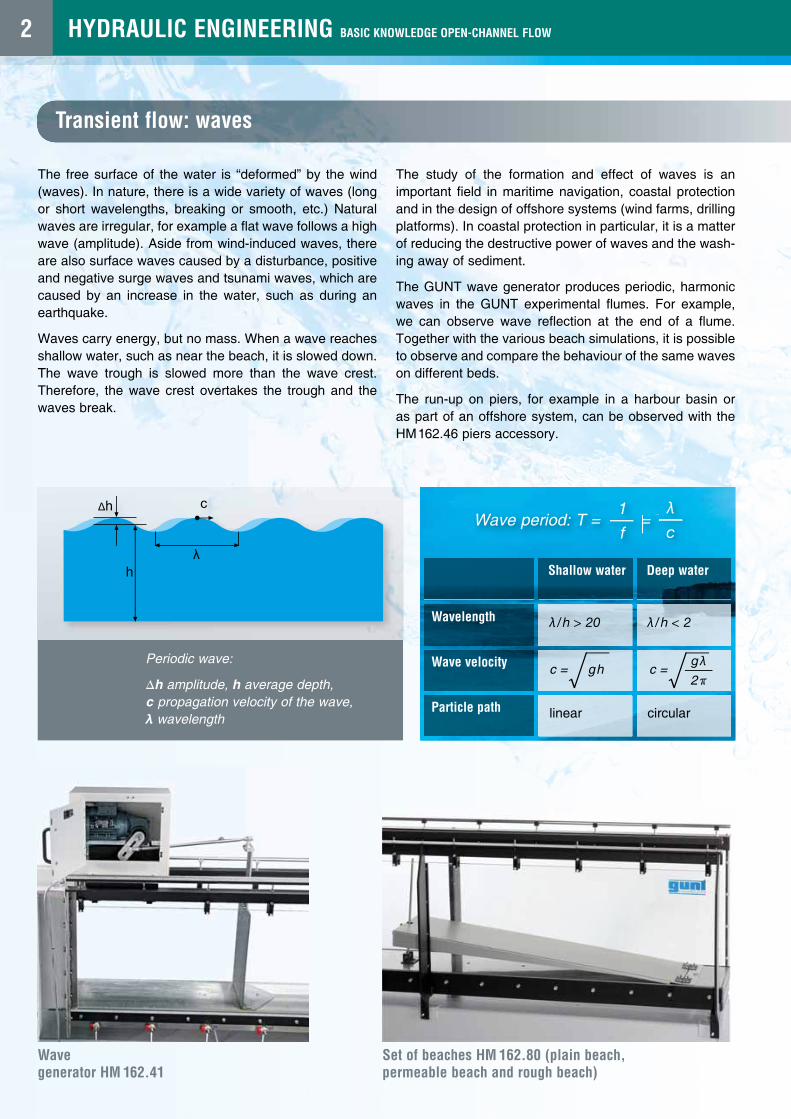
Periodic wave:
∆h amplitude, h average depth,c propagation velocity of the wave,λ wavelength
1
f
λ
cWave period: T = =
Wave generator HM 162.41
Set of beaches HM 162.80 (plain beach, permeable beach and rough beach)
Wavelength
Wave velocity
Particle path linear
λ/h > 20 λ/h < 2
circular
Shallow water Deep water
gλ
2πc = ghc =
2